pump product catalogвиерспм.рф/catalogues/dboun_weir spm pump catalog (english... · •...
TRANSCRIPT

SPM® PumpProduct Catalog
SPM® PUMP PRODUCT CATALOG 1
Table of Contents
2 CORPORATE OVERVIEW 2 CORPORATE PROFILE2 QUALITY, HEALTH, SAFETY AND ENVIRONMENT (QHSE) SYSTEMS - COMMITMENT TO QUALITY - COMMITMENT TO SAFETY2 GLOBAL FOOTPRINT & SERVICES - COMMITMENT TO OUR CUSTOMERS
4 3RD PARTY CERTIFICATIONS
4 EXTENDING PUMP LIFE AND PREVENTATIVE MAINTENANCE 4 GENERAL MAINTENANCE4 RECOMMENDED STORAGE
5 GENERAL SAFETY GUIDE 5 PERSONAL RESPONSIBILITIES5 ON LOCATION5 INSPECTION - REPAIR - TESTING
6 OVERVIEW OF SPM® PUMPS 6 PUMP REFERENCE GUIDE6 SELECTING THE RIGHT PUMP7 COMMON PUMP FORMULAS7 TRIPLEX OR QUINTUPLEX?8 BEST PRACTICES TO EXTEND PUMP SERVICE LIFE8 PUMP DUTY CYCLES
9 CONTINUOUS DUTY PUMPS 9 TEM 2500 FRAC PUMP12 QEM 3000 FRAC PUMP
16 INTERMITTENT DUTY PUMPS 16 TWS 600S HD WELL SERVICE PUMP21 TWS 2250 FRAC PUMP24 TWS 2400 FRAC PUMP27 SPM® DESTINY® TWS 2500 FRAC PUMP30 QWS 1000S HD WELL SERVICE PUMP35 QWS 2500 SD FRAC PUMP38 SPM® DESTINY® QWS 2800 FRAC PUMP
41 SPM® DURALAST® FLUID ENDS 41 SPM® DURALAST™ FLUID END TECHNOLOGY REDUCES YOUR OPERATIONAL EXPENSE

SPM® PUMP PRODUCT CATALOG 2
Corporate Overview Corporate Profile
The Weir Group is a well-established global engineering group, focused on delivering engineering solutions to the oil and gas, minerals, and power sectors. Founded in 1871 and headquartered in Scotland, Weir is one of the fastest-growing engineering companies in the FTSE 100, employing more than 13,000 people throughout our global operations.
Weir’s Pressure Pumping team is a market leader in well service pumps and high pressure flow control equipment. SPM®’s line of reciprocating plunger pumps is used in various applications including fracturing, cementing, and acidizing. The expanding flow control product line features products used to safely transport fluids at high pressure into the wellbore during various well service applications. Weir also utilizes a global network of strategically located service facilities to provide superior post-sale services to our customers, including pump and fluid end repair, iron inspection and product rental.
Quality, Health, Safety and Environment (QHSE) Systems
Weir’s Quality Management System (QMS) is qualified under ISO 9001 and 14001, as well as OHSAS 18001 requirements. Internal audits of SPM’s manufacturing and service centers are performed semi-annually to verify all policies are being followed and that lean focused continuous improvement drives value for the customer. External audits are performed at a minimum of every three years by a third party certifier.
Commitment to Quality The Weir Group is committed to managing its activities to safeguard its employees, clients, and the communities within which Weir operates in addition to the environment. Weir glob-al EHS standards have been disseminated throughout our operations. These standards, based upon a robust risk assessment approach and recognized HSE management systems, provide a platform for continual improvement.
Commitment to Safety Global Footprint & Services
Weir prioritizes its ability to provide a rapid response to service needs through its global network of service centers and skilled technicians. Service center teams are located in close proximity to all major shale plays and key production locations around the world to support customers with all repair and maintenance needs.
Commitment to Our Customers

SPM® PUMP PRODUCT CATALOG 3
Where You Need Us. When You Need Us.

SPM® PUMP PRODUCT CATALOG 4
•Most SPM® products generate, control or direct pressurized fluids; therefore, it is critical that those who work with these products be thoroughly trained in their proper application and safe handling. It is also critical that these products be used and maintained properly.
• It is a personal responsibility to use the proper tools when servicing SPM® pumps. It is a personal responsibility to be knowledgeable and trained in the use and handling of tools for all maintenance of pumps. Operating and Maintenance Instruction Manuals should be consulted before operating product.
•Each pump is clearly marked with a maximum pressure rating. This pressure must not be exceeded.
•A complete visual inspection of equipment must be made prior to each use. Any leaking seals, broken bolts, leaking hoses or improperly tightened parts must be remedied prior to using.
•Personnel must not be around pressure vessel products while pressure is present or being applied.
•Each pump, as well as each component, must have regular intervals of maintenance and inspection for safe, proper performance.
•Never tighten or hammer wing unions when the system is under pressure.
•Welding, brazing or heating on high pressure components is prohibited.
CE and DNV approval for all pump products is offered. Additional third party certifications, such as ABS or BV, may be available upon request. Contact Weir for specific information.
General Maintenance •General maintenance will extend the life of pumping assets. Please refer to the operating manual for specific instructions.
Recommended Storage •Clean and flush the power end with preservation oil and fluid end with rust preventative.
•Plug suction and discharge openings.
•Seal all open fittings and lube ports, remove power end and lube breather cap and plug the hole with a pipe plug. Tie the cap to the pump.
•Coat pinion and pony rods with rust preventative.
•Store inside in a warm, dry place.
• If pump is idle for two or more weeks, remove and lube the plungers and packing with oil before operating.
Third Party Certifications
Extending Pump Life and Preventative Maintenance

SPM® PUMP PRODUCT CATALOG 5
General Safety Guide Personal Responsibilities:
•When using SPM® pumps, appropriate PPE is required, including at a minimum safety glasses, approved safety shoes and hard hat. Lifting these assemblies must be done with caution. See product manual for lifting instructions.
•Personnel should only hammer on union lugs and not strike union nut or valve body. Fractures can occur from repeated misuse. Excessive hammering can damage components.
•Proper lifting equipment rated for the load should be used at all times.
•Do not hammer on SPM® product when pressure is present.
On Location: •Proper transportation of SPM® product is important. Never transport any SPM® product in a fashion that would allow it to become dislodged and cause an accident.
•End connections on SPM® product should be clean and lightly oiled prior to each use. A visual inspection for damage should also be performed at this time. Union seals should be checked, and replaced when worn or damaged.
•Since SPM® product may be repainted in different colors for various applications, do not use the factory as the primary means of service identification. Operator specific color schemes should be used.
•SPM® product usage should be monitored by a qualified supervisor or foreman. Supervisory personnel must approve proper placement, position, and handling of all equipment in the pumping system.
•Do not position any part of your body in the path of exit flow of SPM® flow line equipment.
• It is recommended that a rate in excess of 42 feet per second be avoided. Rates above this will cause rapid wear and erosion.
•After each job flush components with clean water and grease with the proper SPM® approved grease. Follow the instructions in the operations manuals or contact a local Weir representative for assistance.
Inspection - Repair - Testing: •Any unauthorized alteration of SPM® pumping equipment is prohibited.
•Use only repair methods as outlined by SPM® service literature. Use only the proper SPM® repair tools.
•Only SPM® repair and service parts should be used for replacement in SPM® product.
•Weir does not allow weld repair to be attempted on any of its product. Replacing worn components is a more effective and safe approach.

SPM® PUMP PRODUCT CATALOG 6
Weir manufactures a comprehensive range of high-pressure plunger pumps. SPM®‘s plunger pump design incorporates the ultimate in weight and space savings while having a reputation for dependable service even in today’s hybrid extended duty applications.
Weir offers the most powerful continuous duty plunger pumps on the market for today’s challenging fracturing operations. Weir offers intermittent duty pump models for the full range of well service applications. These pumps may be used for oilfield and industrial applications requiring greater work periods at a reduced load.
SPM® intermittent duty plunger pumps are DNV type approved, and range from 600 BHP to 3000 BHP with pressure capabilities up to 20,000 psi. Premium plungers, valves, seats, packing, etc. can be configured to a variety of well service needs from mud based coiled tubing support services to hot oil, cementing, acidizing, fracturing,gravel packing, etc.
SPM® frac pumps are manufactured with life cycle enhancing “auto-frettage” processing of the fluid cylinder. This economical process adjusts for the harmful effects of cyclic stress and the stress corrosion cracking that occurs in high-pressure fluid cylinders. Weir’s state-of-the-art auto-frettage process results in a fluid cylinder with long fatigue life expectancy at a fractional increase in cost.
Weir proudly offers classroom and shop training to better familiarize the customer with the design parameters, technical specifications, and operating characteristics of each pump model.
To further assist our customers, Weir provides an installation audit on “Alpha” units being introduced into their fleet or OEM builds. Please contact your local Weir representative for more details on this service.
Pump Reference Guide
SPM® PUMP MODEL EXPLANATION:
QWS - 2500 - SD 1st letter indicates number of cylinders:
T = triplex
Q = quintuplex
2nd two letters indicate the intended duty cycle:
WS = intermittent, such as well service
EM = Extended Max
HB = extended, such as hydroblast
Numbers indicate max. rated BHP:
2500 = 2500 BHP
Last two letters indicate specialty designation:
SD = super duty
LW = special lightweight design
S = short
HV = horizontal valve
DD = direct drive
HD - heavy duty
Selecting the Right PumpIn order to select the right pump for your application, a number of variables must be considered, including but not limited to:
Required Flow Rate •How much fluid are you pumping?
Discharge Pressure (PSI) •As the flow rate increases, discharge pressure of a given pump will decrease.
Rod Load (At Maximum Pressure) •The force of pressure pushing against the piston will be transmitted back into the frame, so the entire unit is designed, tested, and rated to withstand this load.
Overview of SPM® Pumps

SPM® PUMP PRODUCT CATALOG 7
Engine HP (Brake HP) •How much HP do you have available (or will you need) to deliver the required volume at the required pressure?
Operations •Does your application require 100% capacity at all times when pumping, or will 2 smaller units provide required peak capacity allowing for pumping with 1 unit while the other is undergoing routine maintenance (improving operational efficiency overall)?
Common Pump Formulas •Hydraulic Horse Power (HHP) = (GPM x PSI) / 1714
•Brake Horse Power (BHP) = (GPM X PSI) / (1714 x ME)
•Pressure (PSI) = (BHP x 1714 x ME) / GPM
•GPM = (BHP x 1714 x ME) / PSI
•Rod Load = PD x PD x .7854 x PSI
•GPR = (PD x PD x .7854 x SL x NC) / 231
•GPM = GPR x RPM
Triplex or Quintuplex?The decision to purchase a triplex (3-plunger) or quintuplex (5-plunger) pump is also influenced by a variety of factors, and either one may be the right solution. In general the following tradeoffs should be considered between the two configurations:
Triplex Quint
Higher maximum pressure Higher maximum flow
Lower maximum flow Lower maximum pressure
Smaller footprint Larger footprint
Lower weight Higher weight
Lower HP rating Higher HP rating
Higher peak-to-peak ΔP – pulsation control may be required Pulsation control rarely needed
Driveline damper needed Driveline damper seldom used
The table below lists the main features of our standard pump offerings. Additional information about each pump may be found in this catalog, or by contacting Weir Oil & Gas at 1-800-342-7458.
PumpRecommended
Application# Cyl
Max Brake
HP
Max Rod Load
Max Pressure, 4” Plunger1 Stroke
Gear Ratio
Displacement, 4” Plunger2 Dimensions Weight
TWS 600S HD
Acidizing, cementing,
gravel packing, snubbing
3 600106,000 lbf (48,094 kg)
8,438 psi (58 MPa)
6” (152 mm)
4.61 : 1294 gpm
(1,113 lpm)
50.3” x 52.9” x 23.9” (1,276 mm x 1,344
mm x 607 mm)
4,600 lb (2,086
kg)
TWS 2250 Fracturing 3 2,250238,570 lbf (108,213 kg)
18,985 psi (131 MPa)
8” (203 mm)
6.353 : 1
392 gpm (1,483 lpm)
89.9” x 59.8” x 44.3” (2,284 mm x 1,519 mm x 1,125 mm)
11,750 lb (5,330
kg)
TWS 2400 Fracturing 3 2,400273,000 lbf (123,810 kg)
21,725 psi (150 MPa)
8” (203 mm)
5.588 : 1
392 gpm (1,483 lpm)
90” x 60” x 44” (2,381 mm x 1,519 mm x 1,125 mm)
11,750 lb (5,330
kg)
TWS 2500 Fracturing 3 2,500273,000 lbf (123,810 kg)
21,725 psi (150 MPa)
10” (254 mm)
6.375 : 1
499 gpm (1890 lpm)
91” x 93” x 42” (3,311 mm x 2,362 mm x 1067 mm)
14,450 lb (6,560
kg)
TEM 2500 Fracturing 3 2,500275,000 lbf (124,738 kg)
21,884 psi (151 MPa)
8” (203 mm)
6.963:1392 gpm
(1,487 lpm)
87” x 92” x 54” (2,210 mm x 2,337 mm x 1,372 mm)
21,000 lb (9,525
kg)
BHP - Brake Horsepower GPM - Gallons Per MinuteGPR - Gallons Per RevolutionME - Mechanical EfficiencyNC - Number of CylindersPD - Plunger DiameterPSI - Pounds Per Square InchRPM - Revolutions Per MinuteSL - Stroke Length
continued on next page
Overview of SPM® Pumps (continued)

SPM® PUMP PRODUCT CATALOG 8
PumpRecommended
Application# Cyl
Max Brake
HP
Max Rod Load
Max Pressure, 4” Plunger1 Stroke
Gear Ratio
Displacement, 4” Plunger2 Dimensions Weight
QWS 1000S HD
Acidizing, cementing,
gravel packing, snubbing
5 1,000106,000 lbf (48,094 kg)
8,438 psi (58 MPa)
6” (152 mm)
4.61 : 1490 gpm
(1,855 lpm)
50” x 73” x 24” (1,270 mm x 1,854
mm x 609 mm)
7,040 lb (3,193
kg)
QWS 2500 SD Fracturing 5 2,500192,325 lbf (87,239 kg)
15,305 psi (105 MPa)
8” (203 mm)
6.353 : 1
650 gpm (2,458 lpm)
87.9” x 79.4” x 43.7” (2,233 mm x 2,017 mm x 1,110 mm)
16,000 lb (7,257 kg)
QWS 2800 Fracturing 5 2,800273,000 lbf (123,810 kg)
21,752 psi (150 MPa)
10” (254 mm)
6.933 : 1
816 gpm* (3,087 lpm)
90.0” x 115” x 44” (2,309 mm x 2,921 mm x 1,118 mm)
20,592 lb (9,339
kg)
QEM 3000 Fracturing 5 3,000275,000 lbf (124,738 kg)
21,880 psi (151 MPa)
8” (203 mm)
6.963:1612 gpm
(2,458 lpm)
87” x 116” x 54” (2,210 mm x 2,946 mm x 1,372 mm)
29,500 lb (13,381
kg)
1 - At 50 pump strokes per minute 2 - At 300 pump strokes per minute: note discharge pressure at this displacement rate will be significantly lower than max pressure.3 - Pumps can exceed working pressure of the discharge iron. Care must be taken to match discharge iron maximum working pressures.* - Max velocity is 42 FPS. With 3” iron, do not exceed.
Best Practices to Extend Pump Service Life Operations and Maintenance
Extending pump life requires careful operation by the customer. The customer should observe and utilize the following tools and practices:
• Follow “break-in” procedure for new equipment specified in the operations manual
•Use of a Zoomie manifold to super charge the pump.
•Suction pulsation dampeners (especially recommended for Triplex pumps)
•Properly maintain plungers, packing, valves, and seats
• Improve discharge harmonics (may require high pressure dampener)
•Correct piping placement
•Proper supercharging
•Correct sand/gel concentrations and proper blender operations
Establishing the recommended preventative maintenance (PM) program is the best way to increase the life of your pump and pump components. Weir strongly recommends that each customer establish and follow a PM program for all pumping assets at all times. Details can be found in the pump operations manual, but the general PM recommendations include the following. Further details can be found in the pump operations manual provided with each new pump.
•Daily (leak checks)
•Weekly (additional system leak checks)
•Monthly or every 100 pumping hours (bolts are tight, filter changes, check consumable/wear parts inventories)
•Quarterly or every 250 hours (oil change, clean lube oil strainers and breathers, replace packing)
•Yearly (complete pump inspection, replacing worn components, all flange/manifold seals)
•Oil samples will assist in monitoring the pump.
A properly executed PM program will keep the equipment in top performance, and can prevent or identify problems before they occur. This helps to reduce and eliminate unplanned downtime and expensive lengthy repairs.
Pump Duty CyclesPlease consult your Weir representative for information on pump duty cycles.
Overview of SPM® Pumps (continued)

SPM® PUMP PRODUCT CATALOG 9
Continuous Duty Pumps
APPLICATIONS: Fracturing.
Rated Max. Brake HP .........................................................................................................................2,500 BHP (1,865 kW)Maximum Rod Load ......................................................................................................................275,000 lbf (124,738 kg)Stroke Length ....................................................................................................................................................8” (203 mm)Gear Ratio ...................................................................................................................................................................6.963:1Length ...........................................................................................................................................................87” (2,210 mm)Width ............................................................................................................................................................92” (2,337 mm)Height ...........................................................................................................................................................54” (1,372 mm)Weight Dry (Approx.) ............................................................................................................................21,000 lb (9,525 kg)
Note: Pump dimensions and weight are approximate. For full detailed drawings, please contact Weir.
TEM 2500 PUMP - PERFORMANCE CHART1,2
Plunger Diameter
Displace.Per Rev
DISPLACEMENT AT PUMP STROKES PER MINUTE/PINION RPM
50 348 75 522 110 766 150 1044 250 1741 280 1950
in (mm)
gal/rev (liter/rev)
gpm (lpm)
psi (MPa)
gpm (lpm)
psi (MPa)
gpm (lpm)
psi (MPa)
gpm (lpm)
psi (MPa)
gpm (lpm)
psi (MPa)
gpm (lpm)
psi (MPa)
4 (101.6)
1.31 (4.9)
65 (247)
21884 (151)
98 (371)
21884 (151)
144 (543)
21884 (151)
196 (741)
19692 (136)
326 (1235)
11815 (81)
366 (1384)
10549 (73)
4 1/2 (114.3)
1.65 (6.3)
83 (313)
17291 (119)
124 (469)
17291 (119)
182 (688)
17291 (119)
248 (938)
15559 (107)
413 (1564)
9336 (64)
463 (1751)
8335 (57)
5 (127.)
2.04 (7.7)
102 (386)
14006 (97)
153 (579)
14006 (97)
224 (849)
14006 (97)
306 (1158)
12603 (87)
510 (1930)
7562 (52)
571 (2162)
6752 (46)
INPUT POWER: BHP (kW)
2500 (1866)
2500 (1866)
2500 (1866)
2500 (1866)
2500 (1866)
2500 (1866)
1 Based on 90% ME and 100% VE ---- continuous duty.2 Pumps operating in excess of 15000 psi require special gauge and discharge flanges. Contact a local Weir representative for information.3 Cells highlighted in blue are intermittent zones where velocity through the valves exceeds the recommended rate of 12 FPS.
TEM 2500 Frac PumpThe SPM® TEM 2500 is the industry’s first true continuous duty high horse power stimulation pump designed to handle operation at 275,000 lbf of rod load 100% of the time. Enhanced structural rigidity through an engineered skid and segmented frame plates dramatically extends component life, while a special dual lubrication system ensures adequate delivery of clean lubricant to prevent premature failure.

SPM® PUMP PRODUCT CATALOG 10
0
2000
4000
6000
8000
10000
12000
14000
16000
0 200 400 600 800 1000 1200 1400 1600 1800 2000 2200
2500 BRAKE HORSEPOWER
13,968 ft-lbf MAX
2250 BRAKE HORSEPOWER
SPM® TEM 2500 Pump - Brake Horsepower Curve
PIN
ION
TO
RQ
UE
(lb
f-ft
)
PINION SPEED (RPM)
PR
ES
SU
RE
(P
SI)
FLOW (GPM)
SPM® TEM 2500 Pump - 4.00" Plunger Horsepower Curve
0
4000
2000
6000
8000
12000
14000
10000
16000
24000
22000
20000
18000
0 100 15050 200 250 300 350 400
21,884 MAX PSI, 275,000 LB ROD LOAD
2500 BRAKE HORSEPOWER
2250 BRAKE HORSEPOWER
366
GP
M M
AX
SPECIAL GAUGE & DISCHARGE FLANGES
REQUIRED IN THIS ZONE
TEM 2500 Frac Pump (continued)

SPM® PUMP PRODUCT CATALOG 11
TEM 2500 Frac Pump (continued)
PR
ES
SU
RE
(P
SI)
FLOW (GPM)
SPM® TEM 2500 Pump - 4.50" Plunger Horsepower Curve
0
4000
2000
6000
8000
12000
14000
10000
16000
20000
18000
0 100 15050 200 250 300 350 400 450 500
17,291 MAX PSI, 275,000 LB ROD LOAD
2500 BRAKE HORSEPOWER
2250 BRAKE HORSEPOWER
463
GP
M M
AX
SPECIAL GAUGE & DISCHARGE FLANGES REQUIRED IN THIS ZONE
PR
ES
SU
RE
(P
SI)
FLOW (GPM)
SPM® TEM 2500 Pump - 5.00" Plunger Horsepower Curve
0
4000
2000
6000
8000
12000
14000
10000
16000
0 100 15050 200 250 300 350 400 450 500 550 600 650
14,006 MAX PSI, 275,000 LB ROD LOAD
2500 BRAKE HORSEPOWER
2250 BRAKE HORSEPOWER
571
GP
M M
AX
SPM® PUMP PRODUCT CATALOG 12
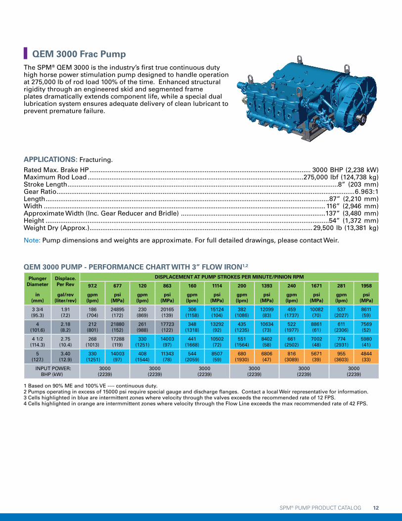
APPLICATIONS: Fracturing.
Rated Max. Brake HP ......................................................................................................................... 3000 BHP (2,238 kW)Maximum Rod Load ......................................................................................................................275,000 lbf (124,738 kg)Stroke Length ....................................................................................................................................................8” (203 mm)Gear Ratio ...................................................................................................................................................................6.963:1Length ...........................................................................................................................................................87” (2,210 mm)Width .......................................................................................................................................................... 116” (2,946 mm)Approximate Width (Inc. Gear Reducer and Bridle) ...............................................................................137” (3,480 mm)Height ...........................................................................................................................................................54” (1,372 mm)Weight Dry (Approx.) ..........................................................................................................................29,500 lb (13,381 kg)
Note: Pump dimensions and weights are approximate. For full detailed drawings, please contact Weir.
QEM 3000 PUMP - PERFORMANCE CHART WITH 3” FLOW IRON1,2
Plunger Diameter
Displace.Per Rev
DISPLACEMENT AT PUMP STROKES PER MINUTE/PINION RPM
97.2 677 120 863 160 1114 200 1393 240 1671 281 1958
in (mm)
gal/rev (liter/rev)
gpm (lpm)
psi (MPa)
gpm (lpm)
psi (MPa)
gpm (lpm)
psi (MPa)
gpm (lpm)
psi (MPa)
gpm (lpm)
psi (MPa)
gpm (lpm)
psi (MPa)
3 3/4 (95.3)
1.91 (7.2)
186 (704)
24895 (172)
230 (869)
20165 (139)
306 (1158)
15124 (104)
382 (1086)
12099 (83)
459 (1737)
10082 (70)
537 (2027)
8611 (59)
4 (101.6)
2.18 (8.2)
212 (801)
21880 (152)
261 (988)
17723 (122)
348 (1318)
13292 (92)
435 (1235)
10634 (73)
522 (1977)
8861 (61)
611 (2306)
7569 (52)
4 1/2 (114.3)
2.75 (10.4)
268 (1013)
17288 (119)
330 (1251)
14003 (97)
441 (1668)
10502 (72)
551 (1564)
8402 (58)
661 (2502)
7002 (48)
774 (2931)
5980 (41)
5 (127.)
3.40 (12.9)
330 (1251)
14003 (97)
408 (1544)
11343 (78)
544 (2059)
8507 (59)
680 (1930)
6806 (47)
816 (3089)
5671 (39)
955 (3603)
4844 (33)
INPUT POWER: BHP (kW)
3000 (2239)
3000 (2239)
3000 (2239)
3000 (2239)
3000 (2239)
3000 (2239)
1 Based on 90% ME and 100% VE ---- continuous duty.2 Pumps operating in excess of 15000 psi require special gauge and discharge flanges. Contact a local Weir representative for information.3 Cells highlighted in blue are intermittent zones where velocity through the valves exceeds the recommended rate of 12 FPS.4 Cells highlighted in orange are intermmittent zones where velocity through the Flow Line exceeds the max recommended rate of 42 FPS.
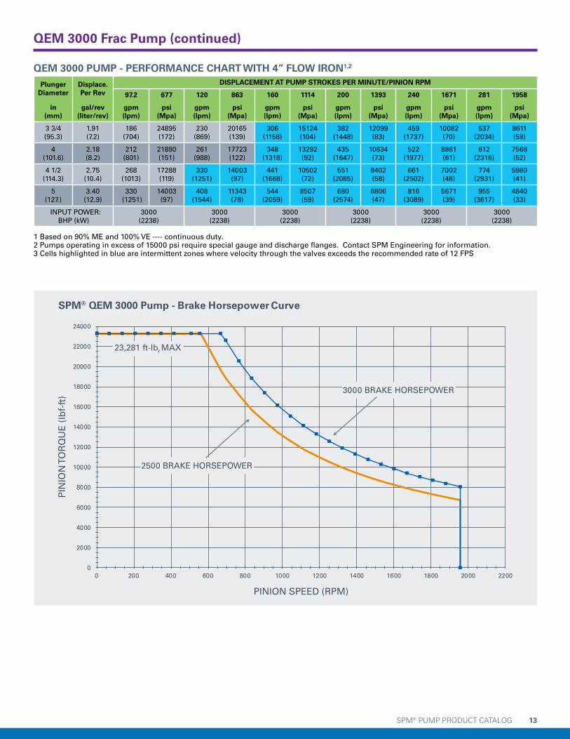
QEM 3000 Frac PumpThe SPM® QEM 3000 is the industry’s first true continuous duty high horse power stimulation pump designed to handle operation at 275,000 lb of rod load 100% of the time. Enhanced structural rigidity through an engineered skid and segmented frame plates dramatically extends component life, while a special dual lubrication system ensures adequate delivery of clean lubricant to prevent premature failure.
SPM® PUMP PRODUCT CATALOG 13
QEM 3000 PUMP - PERFORMANCE CHART WITH 4” FLOW IRON1,2
Plunger Diameter
Displace.Per Rev
DISPLACEMENT AT PUMP STROKES PER MINUTE/PINION RPM
97.2 677 120 863 160 1114 200 1393 240 1671 281 1958
in (mm)
gal/rev (liter/rev)
gpm (lpm)
psi (Mpa)
gpm (lpm)
psi (Mpa)
gpm (lpm)
psi (Mpa)
gpm (lpm)
psi (Mpa)
gpm (lpm)
psi (Mpa)
gpm (lpm)
psi (Mpa)
3 3/4 (95.3)
1.91 (7.2)
186 (704)
24895 (172)
230 (869)
20165 (139)
306 (1158)
15124 (104)
382 (1448)
12099 (83)
459 (1737)
10082 (70)
537 (2034)
8611 (59)
4 (101.6)
2.18 (8.2)
212 (801)
21880 (151)
261 (988)
17723 (122)
348 (1318)
13292 (92)
435 (1647)
10634 (73)
522 (1977)
8861 (61)
612 (2316)
7568 (52)
4 1/2 (114.3)
2.75 (10.4)
268 (1013)
17288 (119)
330 (1251)
14003 (97)
441 (1668)
10502 (72)
551 (2085)
8402 (58)
661 (2502)
7002 (48)
774 (2931)
5980 (41)
5 (127.)
3.40 (12.9)
330 (1251)
14003 (97)
408 (1544)
11343 (78)
544 (2059)
8507 (59)
680 (2574)
6806 (47)
816 (3089)
5671 (39)
955 (3617)
4840 (33)
INPUT POWER: BHP (kW)
3000 (2238)
3000 (2238)
3000 (2238)
3000 (2238)
3000 (2238)
3000 (2238)
1 Based on 90% ME and 100% VE ---- continuous duty.2 Pumps operating in excess of 15000 psi require special gauge and discharge flanges. Contact SPM Engineering for information.3 Cells highlighted in blue are intermittent zones where velocity through the valves exceeds the recommended rate of 12 FPS
0
2000
4000
6000
8000
10000
12000
14000
16000
18000
20000
24000
22000
0 200 400 600 800 1000 1200 1400 1600 1800 2000 2200
3000 BRAKE HORSEPOWER
23,281 ft-lbf MAX
2500 BRAKE HORSEPOWER
SPM® QEM 3000 Pump - Brake Horsepower Curve
PIN
ION
TO
RQ
UE
(lb
f-ft
)
PINION SPEED (RPM)
QEM 3000 Frac Pump (continued)

SPM® PUMP PRODUCT CATALOG 14
QEM 3000 Frac Pump (continued)
PR
ES
SU
RE
(P
SI)
FLOW (GPM)
SPM® QEM 3000 Pump - 3.75" Plunger Horsepower Curve
0
5000
10000
15000
20000
25000
30000
0 100 200 400300 600500
3000 BRAKE HORSEPOWER
2500 BRAKE HORSEPOWER
538
GP
M M
AX
24,895 MAX PSI, 275,000 LB ROD LOAD
SPECIAL GAUGE & DISCHARGE FLANGES
REQUIRED IN THIS ZONE
PR
ES
SU
RE
(P
SI)
FLOW (GPM)
SPM® QEM 3000 Pump - 4.00" Plunger Horsepower Curve
0 100 200 400300 700600500
0
4000
2000
6000
8000
12000
14000
10000
16000
20000
18000
22000
24000
3000 BRAKE HORSEPOWER
2500 BRAKE HORSEPOWER
612
GP
M M
AX
21,880 MAX PSI, 275,000 LB ROD LOAD
SPECIAL GAUGE & DISCHARGE FLANGES
REQUIRED IN THIS ZONE

SPM® PUMP PRODUCT CATALOG 15
PR
ES
SU
RE
(P
SI)
FLOW (GPM)
SPM® QEM 3000 Pump - 4.50" Plunger Horsepower Curve
0 100 200 400300 900800700600500
0
4000
2000
6000
8000
12000
14000
10000
16000
20000
18000
3000 BRAKE HORSEPOWER
2500 BRAKE HORSEPOWER
42 FPS WITH 3" IRON AT 642 GPM
774
GP
M M
AX
17,288 MAX PSI, 275,000 LB ROD
SPECIAL GAUGE & DISCHARGE FLANGES
REQUIRED IN THIS ZONE
HIGH FLOW ZONE
PR
ES
SU
RE
(P
SI)
FLOW (GPM)
SPM® QEM 3000 Pump - 5.00" Plunger Horsepower Curve
0 100 200 400300 110010000900800700600500
0
4000
2000
6000
8000
12000
14000
10000
16000
3000 BRAKE HORSEPOWER
2500 BRAKE HORSEPOWER
42 FPS WITH 3" IRON AT 642 GPM
956
GP
M M
AX
14,003 MAX PSI, 275,000 LB ROD LOAD
HIGH FLOW ZONE
QEM 3000 Frac Pump (continued)

SPM® PUMP PRODUCT CATALOG 16
APPLICATIONS: Cementing, acidizing, gravel packing, snubbing.
Rated Max. Brake HP ...............................................................................................................................600 BHP (447 kW)Maximum Rod Load ........................................................................................................................106,000 lbf (48,094 kg)Number of Cylinders ...........................................................................................................................................................3 Stroke Length .................................................................................................................................................6” (152.4 mm)Gear Ratio .....................................................................................................................................................................4.61:1Length ...........................................................................................................................................................50” (1,270 mm)Width ............................................................................................................................................................53” (1,346 mm)Height ..............................................................................................................................................................24” (610 mm)Weight Dry (Approx.) ..............................................................................................................................4,600 lb (2,086 kg)
Note: Pump dimensions and weight are approximate. For full, detailed drawings, please contact Weir.
TWS 600S HD PUMP PERFORMANCE CHART1,2
Plunger Diameter
Displace.Per Rev
DISPLACEMENT AT PUMP STROKES PER MINUTE/PINION RPM
50 231 100 461 112 516 200 922 350 1614 455 2096
in (mm)
gal/rev (liter/rev)
gpm (lpm)
psi (MPa)
gpm (lpm)
psi (MPa)
gpm (lpm)
psi (MPa)
gpm (lpm)
psi (MPa)
gpm (lpm)
psi (MPa)
gpm (lpm)
psi (MPa)
2 1/2 (63.5)
0.38 (1.4)
19 (72)
21600 (149)
38 (145)
21600 (149)
43 (162)
21599 (149)
76 (290)
12099 (84)
134 (507)
6914 (48)
174 (658)
5322 (37)
2 3/4 (69.9)
0.46 (1.8)
23 (88)
17851 (123)
46 (175)
17851 (123)
52 (196)
17851 (123)
93 (350)
9999 (69)
162 (613)
5714 (40)
210 (797)
4398 (30)
3 (76.2)
0.55 (2.1)
28 (104)
15000 (104)
55 (208)
15000 (104)
62 (234)
15000 (104)
110 (417)
8402 (58)
193 (730)
4801 (33)
250 (948)
3696 (26)
3 1/2 (88.9)
0.75 (2.8)
37 (142)
11020 (76)
75 (284)
11020 (76)
84 (318)
11020 (76)
150 (568)
6173 (43)
262 (993)
3527 (24)
341 (1290)
2715 (19)
4 (101.6)
0.98 (3.7)
49 (185)
8438 (58)
98 (371)
8438 (58)
110 (415)
8437 (58)
196 (741)
4726 (33)
343 (1297)
2701 (19)
445 (1685)
2079 (14)
4 1/2 (114.3)
1.24 (4.7)
62 (235)
6667 (46)
124 (469)
6667 (46)
139 (526)
6666 (46)
248 (938)
3734 (263)
434 (1642)
2134 (15)
564 (2133)
1642 (11)
INPUT POWER: BHP (kW)
268 (200)
536 (400)
600 (448)
600 (448)
600 (448)
600 (448)
1 Based on 90% ME and 100% VE ---- intermittent service only.2 Pumps operating in excess of 15000 psi require special gauge and discharge flanges. Contact a local Weir representative for information.3 Cells highlighted in blue are intermediate zones where erosion is more prevalent when 3” iron is used (MAX 778GPM).
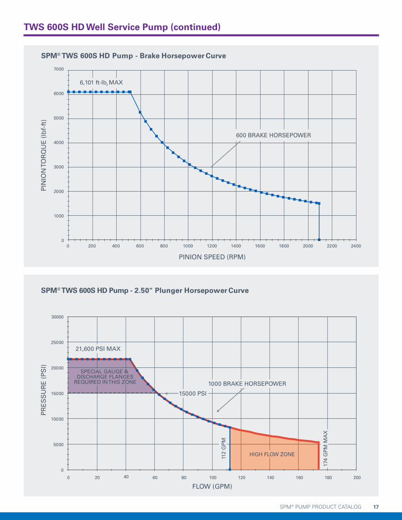
Intermittent Duty Pumps TWS 600S HD Well Service Pump
The SPM® TWS 600S HD pump is specifically engineered to reduce downtime due to maintenance while improving rod load and high pressure capabilities. The Heavy Duty design is built with quick and practical maintenance in mind, while supplying 6% higher rod load at pressures of 15,000 psi utilizing a 3” plunger and 20,000 psi utilizing a 2.5” plunger. The TWS 600S HD pump is designed to eliminate contamination from pumping media into the power end, extending pump component life. Retrofit kits are available for customers currently operating TWS 600S pumps, helping them make the transition to the TWS 600S HD pump. Customers are able to update their units to the latest technology without the capital investment of a complete new unit.
SPM® PUMP PRODUCT CATALOG 17
0
1000
2000
3000
4000
5000
6000
7000
0 200 400 600 800 1000 1200 1400 1600 1800 2000 2200 2400
600 BRAKE HORSEPOWER
6,101 ft-lbf MAX
SPM® TWS 600S HD Pump - Brake Horsepower Curve
PIN
ION
TO
RQ
UE
(lb
f-ft
)
PINION SPEED (RPM)
PR
ES
SU
RE
(P
SI)
FLOW (GPM)
SPM® TWS 600S HD Pump - 2.50" Plunger Horsepower Curve
0
5000
10000
15000
20000
25000
30000
0 20 40 60 100 160 180 20080 140120
1000 BRAKE HORSEPOWER
174
GP
M M
AX
112
GP
M
21,600 PSI MAX
HIGH FLOW ZONE
SPECIAL GAUGE & DISCHARGE FLANGES
REQUIRED IN THIS ZONE
15000 PSI
TWS 600S HD Well Service Pump (continued)

SPM® PUMP PRODUCT CATALOG 18
PR
ES
SU
RE
(P
SI)
FLOW (GPM)
SPM® TWS 600S HD Pump - 2.75" Plunger Horsepower Curve
0
3000
6000
9000
12000
15000
18000
0 20 40 60 100 160 180 220 24020080 140120
600 BRAKE HORSEPOWER
210
GP
M M
AX
112
GP
M
17,851 PSI MAX
HIGH FLOW ZONE
SPECIAL GAUGE & DISCHARGE FLANGES
REQUIRED IN THIS ZONE15000 PSI
PR
ES
SU
RE
(P
SI)
FLOW (GPM)
SPM® TWS 600S HD Pump - 3.00" Plunger Horsepower Curve
0
6000
4000
2000
8000
10000
12000
14000
16000
0 20 40 60 100 160 180 220 280240 26020080 140120
600 BRAKE HORSEPOWER
250
GP
M M
AX
112
GP
M M
AX
15,000 PSI MAX
HIGH FLOW ZONE
TWS 600S HD Well Service Pump (continued)
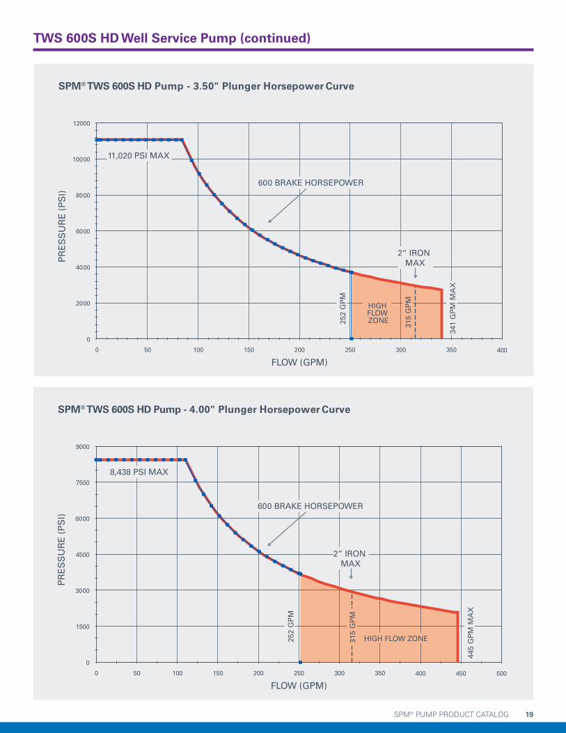
SPM® PUMP PRODUCT CATALOG 19
PR
ES
SU
RE
(P
SI)
FLOW (GPM)
SPM® TWS 600S HD Pump - 3.50" Plunger Horsepower Curve
0
2000
4000
6000
8000
10000
12000
0 50 100 300 400350150 250200
341
GP
M M
AX
252
GP
M
11,020 PSI MAX
HIGH FLOW ZONE
2” IRON MAX
315
GP
M
600 BRAKE HORSEPOWER
PR
ES
SU
RE
(P
SI)
FLOW (GPM)
SPM® TWS 600S HD Pump - 4.00" Plunger Horsepower Curve
0
1500
3000
4500
6000
7500
9000
0 50 100 300 500450400350150 250200
445
GP
M M
AX
252
GP
M
8,438 PSI MAX
2” IRON MAX
HIGH FLOW ZONE315
GP
M
600 BRAKE HORSEPOWER
TWS 600S HD Well Service Pump (continued)

SPM® PUMP PRODUCT CATALOG 20
PR
ES
SU
RE
(P
SI)
FLOW (GPM)
SPM® TWS 600S HD Pump - 4.50" Plunger Horsepower Curve
0
1000
2000
3000
5000
4000
6000
7000
0 50 100 300 650600550500450400350150 250200
564
GP
M M
AX
252
GP
M
6,667 PSI MAX
2” IRON MAX
HIGH FLOW ZONE
600 BRAKE HORSEPOWER
315
GP
M
TWS 600S HD Well Service Pump (continued)
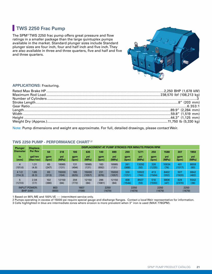
SPM® PUMP PRODUCT CATALOG 21
APPLICATIONS: Fracturing.
Rated Max Brake HP ..........................................................................................................................2,250 BHP (1,678 kW)Maximum Rod Load ...................................................................................................................... 238,570 lbf (108,213 kg)Number of Cylinders ...........................................................................................................................................................3Stroke Length ....................................................................................................................................................8” (203 mm)Gear Ratio ...................................................................................................................................................................6.353:1Length ........................................................................................................................................................89.9” (2,284 mm)Width .........................................................................................................................................................59.8” (1,519 mm)Height ........................................................................................................................................................44.3” (1,125 mm)Weight Dry (Approx.) .............................................................................................................................11,750 lb (5,330 kg)
Note: Pump dimensions and weight are approximate. For full, detailed drawings, please contact Weir.
TWS 2250 PUMP - PERFORMANCE CHART1,2
Plunger Diameter
Displace.Per Rev
DISPLACEMENT AT PUMP STROKES PER MINUTE/PINION RPM
50 318 100 635 140 889 200 1271 250 1588 307 1950
in (mm)
gal/rev (liter/rev)
gpm (lpm)
psi (MPa)
gpm (lpm)
psi (MPa)
gpm (lpm)
psi (MPa)
gpm (lpm)
psi (MPa)
gpm (lpm)
psi (MPa)
gpm (lpm)
psi (MPa)
4 (101.6)
1.31 (4.9)
65 (247)
18985 (131)
131 (494)
18985 (131)
183 (692)
18985 (131)
261 (988)
13292 (92)
326 (1235)
10634 (74)
401 (1517)
8659 (60)
4 1/2 (114.3)
1.65 (6.3)
83 (313)
15000 (104)
165 (625)
15000 (1057)
231 (876)
15000 (1057)
330 (1251)
10502 (740)
413 (1564)
8402 (592)
507 (1920)
6842 (482)
5 (127.0)
2.04 (7.7)
102 (386)
12150 (84)
204 (772)
12150 (84)
286 (1081)
12150 (84)
408 (1544)
8507 (59)
510 (1930)
6806 (47)
626 (2370)
5542 (38)
INPUT POWER: BHP (kW)
803 (600)
1607 (1199)
2250 (1679)
2250 (1679)
2250 (1679)
2250 (1679)
1 Based on 90% ME and 100% VE ---- intermittent service only.2 Pumps operating in excess of 15000 psi require special gauge and discharge flanges. Contact a local Weir representative for information.3 Cells highlighted in blue are intermediate zones where erosion is more prevalent when 3” iron is used (MAX 778GPM).
TWS 2250 Frac PumpThe SPM® TWS 2250 frac pump offers great pressure and flow ratings in a smaller package than the large quintuplex pumps available in the market. Standard plunger sizes include Standard plunger sizes are four inch, four and half inch and five inch. They are also available in three and three quarters, five and half and five and three quarters.

SPM® PUMP PRODUCT CATALOG 22
0
2000
4000
6000
8000
10000
12000
14000
16000
0 200 400 600 800 1000 1200 1400 1600 1800 2000 2200
2250 BRAKE HORSEPOWER
13,281 ft-lbf MAX
SPM® TWS 2250 Pump - Brake Horsepower Curve
PIN
ION
TO
RQ
UE
(lb
f-ft
)
PINION SPEED (RPM)
PR
ES
SU
RE
(P
SI)
FLOW (GPM)
PINION (RPM)
SPM® TWS 2250 Pump - 4.00" Plunger Horsepower Curve
0 200 400 600 800 1000 1200 1400 1600 1800 2000 2200
0
4000
2000
6000
8000
12000
14000
10000
16000
20000
18000
22000
0 50 100 150 200 250 300 350 400 450
2250 BRAKE HORSEPOWER
256
GP
M
401
GP
M
18,985 PSI MAX
SPECIAL GAUGE & DISCHARGE FLANGES
REQUIRED IN THIS ZONE15000 PSI
2” IRON
HIGH FLOW ZONE
TWS 2250 Frac Pump (continued)

SPM® PUMP PRODUCT CATALOG 23
TWS 2250 Frac Pump (continued)
PR
ES
SU
RE
(P
SI)
FLOW (GPM)
PINION (RPM)
SPM® TWS 2250 Pump - 4.50" Plunger Horsepower Curve
0 200 400 600 800 1000 1200 1400 1600 1800 2000 2200
0
4000
2000
6000
8000
12000
14000
10000
16000
0 100 200 300 400 600500
2250 BRAKE HORSEPOWER
507
GP
M M
AX
15,000 PSI MAX
2” IRON
HIGH FLOW ZONE315
GP
M
PR
ES
SU
RE
(P
SI)
FLOW (GPM)
PINION (RPM)
SPM® TWS 2250 Pump - 5.00" Plunger Horsepower Curve
0 200 400 600 800 1000 1200 1400 1600 1800 2000
0
4000
2000
6000
8000
12000
14000
10000
0 100 200 300 400 700600500
2250 BRAKE HORSEPOWER
626
GP
M M
AX
12,150 PSI MAX
2” IRON MAX
HIGH FLOW ZONE
315
GP
M
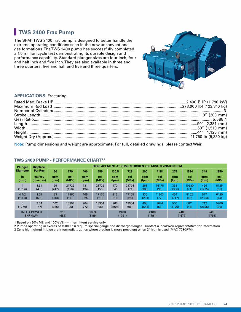
SPM® PUMP PRODUCT CATALOG 24
APPLICATIONS: Fracturing.
Rated Max. Brake HP .........................................................................................................................2,400 BHP (1,790 kW) Maximum Rod Load ......................................................................................................................273,000 lbf (123,810 kg)Number of Cylinders ...........................................................................................................................................................3 Stroke Length ....................................................................................................................................................8” (203 mm)Gear Ratio ...................................................................................................................................................................5.588:1Length ...........................................................................................................................................................90” (2,381 mm)Width ............................................................................................................................................................60” (1,519 mm)Height ...........................................................................................................................................................44” (1,125 mm)Weight Dry (Approx.) .............................................................................................................................11,750 lb (5,330 kg)
Note: Pump dimensions and weight are approximate. For full, detailed drawings, please contact Weir.
TWS 2400 PUMP - PERFORMANCE CHART1,2
Plunger Diameter
Displace.Per Rev
DISPLACEMENT AT PUMP STROKES PER MINUTE/PINION RPM
50 279 100 559 130.5 729 200 1118 275 1534 349 1950
in (mm)
gal/rev (liter/rev)
gpm (lpm)
psi (MPa)
gpm (lpm)
psi (MPa)
gpm (lpm)
psi (MPa)
gpm (lpm)
psi (MPa)
gpm (lpm)
psi (MPa)
gpm (lpm)
psi (MPa)
4 (101.6)
1.31 (4.9)
65 (247)
21725 (150)
131 (494)
21725 (150)
170 (645)
21724 (171)
261 (988)
14178 (98)
358 (1356)
10330 (71)
456 (1725)
8125 (56)
4 1/2 (114.3)
1.65 (6.3)
83 (313)
17165 (119)
165 (625)
17165 (119)
216 (816)
17165 (119)
330 (1251)
11203 (77)
454 (1717)
8162 (56)
577 (2183)
6420 (44)
5 (127.0)
2.04 (7.7)
102 (386)
13904 (96)
204 (772)
13904 (96)
266 (1008)
13904 (96)
408 (1544)
9074 (63)
560 (2120)
6611 (46)
712 (2695)
5200 (36)
INPUT POWER: BHP (kW)
919 (686)
1839 (1199)
2400 (1791)
2400 (1791)
2400 (1679)
2400 (1791)
1 Based on 90% ME and 100% VE ---- intermittent service only.2 Pumps operating in excess of 15000 psi require special gauge and discharge flanges. Contact a local Weir representative for information.3 Cells highlighted in blue are intermediate zones where erosion is more prevalent when 3” iron is used (MAX 778GPM).
TWS 2400 Frac PumpThe SPM® TWS 2400 frac pump is designed to better handle the extreme operating conditions seen in the new unconventional gas formations. The TWS 2400 pump has successfully completed a 1.5 million cycle test demonstrating its durable design and performance capability. Standard plunger sizes are four inch, four and half inch and five inch. They are also available in three and three quarters, five and half and five and three quarters.

SPM® PUMP PRODUCT CATALOG 25
0
2000
4000
6000
8000
10000
12000
14000
18000
20000
16000
0 200 400 600 800 1000 1200 1400 1600 1800 2000 2200
2400 BRAKE HORSEPOWER
17,279 ft-lbf MAX
SPM® TWS 2400 Pump - Brake Horsepower Curve
PIN
ION
TO
RQ
UE
(lb
f-ft
)
PINION SPEED (RPM)
PR
ES
SU
RE
(P
SI)
FLOW (GPM)
PINION (RPM)
SPM® TWS 2400 Pump - 4.00" Plunger Horsepower Curve
0 200 400 600 800 1000 1200 1400 1600 1800 2000 2200
0
4000
2000
6000
8000
12000
14000
10000
16000
20000
18000
22000
24000
0 50 100 150 200 250 300 350 400 450 500
2400 BRAKE HORSEPOWER
256
GP
M
456
GP
M
315
GP
M
21,725 PSI MAX
HIGH FLOW ZONE
SPECIAL GAUGE & DISCHARGE FLANGES
REQUIRED IN THIS ZONE
15000 PSI
2” IRON
TWS 2400 Frac Pump (continued)

SPM® PUMP PRODUCT CATALOG 26
PR
ES
SU
RE
(P
SI)
FLOW (GPM)
PINION (RPM)
SPM® TWS 2400 Pump - 4.50" Plunger Horsepower Curve
0 200 400 600 800 1000 1200 1400 1600 1800 2000 2200
0
4000
2000
6000
8000
12000
14000
10000
16000
20000
18000
0 100 200 300 400 500 600 700
2400 BRAKE HORSEPOWER
577
GP
M
17,165 PSI MAX
SPECIAL GAUGE & DISCHARGE FLANGES
REQUIRED IN THIS ZONE2” IRON
MAX
315
GP
M
PR
ES
SU
RE
(P
SI)
FLOW (GPM)
PINION (RPM)
SPM® TWS 2400 Pump - 5.00" Plunger Horsepower Curve
0 200 400 600 800 1000 1200 1400 1600 1800 2000
0
4000
2000
6000
8000
12000
14000
10000
16000
0 100 200 300 400 500 600 800700
2400 BRAKE HORSEPOWER
721
GP
M
13,904 PSI MAX 2” IRON MAX
315
GP
M
HIGH FLOW ZONE
TWS 2400 Frac Pump (continued)
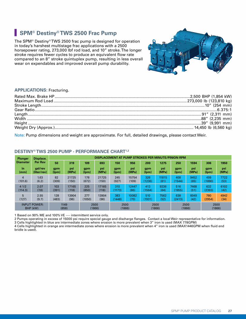
SPM® PUMP PRODUCT CATALOG 27
APPLICATIONS: Fracturing.
Rated Max. Brake HP .........................................................................................................................2,500 BHP (1,854 kW) Maximum Rod Load ....................................................................................................................... 273,000 lb (123,810 kg)Stroke Length ..................................................................................................................................................10” (254 mm)Gear Ratio ...................................................................................................................................................................6.375:1Length ........................................................................................................................................................... 91” (2,311 mm)Width ............................................................................................................................................................88” (2,235 mm)Height ...........................................................................................................................................................39” (9,991 mm)Weight Dry (Approx.) ............................................................................................................................ 14,450 lb (6,560 kg)
Note: Pump dimensions and weight are approximate. For full, detailed drawings, please contact Weir.
DESTINY® TWS 2500 PUMP - PERFORMANCE CHART1,2
Plunger Diameter
Displace.Per Rev
DISPLACEMENT AT PUMP STROKES PER MINUTE/PINION RPM
50 319 109 693 150 956 200 1275 250 1594 306 1950
in (mm)
gal/rev (liter/rev)
gpm (lpm)
psi (MPa)
gpm (lpm)
psi (MPa)
gpm (lpm)
psi (MPa)
gpm (lpm)
psi (MPa)
gpm (lpm)
psi (MPa)
gpm (lpm)
psi (MPa)
4 (101.6)
1.63 (6.2)
82 (309)
21725 (150)
178 (672)
21725 (150)
245 (927)
15754 (109)
326 (1236)
11815 (81)
408 (1544)
9452 (65)
499 (1890)
7722 (53)
4 1/2 (114.3)
2.07 (7.8)
103 (391)
17165 (118)
225 (850)
17165 (118)
310 (1173)
12447 (86)
413 (1564)
9336 (64)
516 (1955)
7468 (51)
632 (2393)
6102 (42)
5 (127)
2.55 (9.7)
128 (483)
13904 (96)
277 (1050)
13904 (96)
383 (1448)
10082 (70)
510 (1931)
7562 (52)
638 (2413)
6049 (42)
780 (2954)
4942 (34)
INPUT POWER: BHP (kW)
1149 (858)
2500 (1866)
2500 (1866)
2500 (1866)
2500 (1866)
2500 (1866)
1 Based on 90% ME and 100% VE ---- intermittent service only.2 Pumps operating in excess of 15000 psi require special gauge and discharge flanges. Contact a local Weir representative for information.3 Cells highlighted in blue are intermediate zones where erosion is more prevalent when 3” iron is used (MAX 778GPM)4 Cells highlighted in orange are intermediate zones where erosion is more prevalent when 4” iron is used (MAX1446GPM when fluid end bridle is used).
SPM® Destiny® TWS 2500 Frac PumpThe SPM® Destiny® TWS 2500 frac pump is designed for operation in today’s harshest multistage frac applications with a 2500 horsepower rating, 273,000 lbf rod load, and 10” stroke. The longer stroke requires fewer cycles to produce an equivalent flow rate compared to an 8” stroke quintuplex pump, resulting in less overall wear on expendables and improved overall pump durability.

SPM® PUMP PRODUCT CATALOG 28
0
2000
4000
6000
8000
10000
12000
14000
18000
20000
16000
0 200 400 600 800 1000 1200 1400 1600 1800 2000 2200
2500 BRAKE HORSEPOWER
18,932 ft-lbf MAX
SPM® Destiny® TWS 2500 Pump - Brake Horsepower Curve
PIN
ION
TO
RQ
UE
(lb
f-ft
)
PINION SPEED (RPM)
PR
ES
SU
RE
(P
SI)
FLOW (GPM)
PINION (RPM)
SPM® Destiny® TWS 2500 Pump - 4.00" Plunger Horsepower Curve
0 200 400 600 800 1000 1200 1400 1600 1800 2000
0
4000
2000
6000
8000
12000
14000
10000
16000
20000
18000
22000
24000
0 50 100 150 200 250 300 350 400 450 550500
2500 BRAKE HORSEPOWER
256
GP
M
499
GP
M
315
GP
M
21,725 PSI MAX
HIGH FLOW ZONE
SPECIAL GAUGE & DISCHARGE FLANGES
REQUIRED IN THIS ZONE
15000 PSI
2” IRON
SPM® Destiny® TWS 2500 Frac Pump (continued)

SPM® PUMP PRODUCT CATALOG 29
SPM® Destiny® TWS 2500 Frac Pump (continued)
PR
ES
SU
RE
(P
SI)
FLOW (GPM)
PINION (RPM)
SPM® Destiny® TWS 2500 Pump - 4.50" Plunger Horsepower Curve
0 200 400 600 800 1000 1200 1400 1600 1800 2000
0
4000
2000
6000
8000
12000
14000
10000
16000
20000
18000
22000
24000
0 100 200 300 400 700500 600
2500 BRAKE HORSEPOWER
300
GP
M
632
GP
M
17,165 PSI MAX
HIGH FLOW ZONE
SPECIAL GAUGE & DISCHARGE FLANGES
REQUIRED IN THIS ZONE2” IRON
315
GP
M
PR
ES
SU
RE
(P
SI)
FLOW (GPM)
PINION (RPM)
SPM® Destiny® TWS 2500 Pump - 5.00" Plunger Horsepower Curve
0 200 400 600 800 1000 1200 1400 1600 1800 2000 2000
0
4000
2000
6000
8000
12000
14000
10000
16000
0 100 200 300 400 900700 800500 600
2500 BRAKE HORSEPOWER
300
GP
M
780
GP
M13,904 PSI MAX
HIGH FLOW ZONE
2” IRON MAX
315
GP
M
3” IRON MAX778 GPM

SPM® PUMP PRODUCT CATALOG 30
APPLICATIONS: Cementing, acidizing, gravel packing, snubbing.
Rated Max Brake HP .............................................................................................................................1,000 BHP (746 kW)Maximum Rod Load ........................................................................................................................106,000 lbf (48,094 kg)Number of Cylinders ...........................................................................................................................................................5 Stroke Length .................................................................................................................................................6” (152.4 mm)Gear Ratio .....................................................................................................................................................................4.61:1Length ...........................................................................................................................................................50” (1,270 mm)Width ............................................................................................................................................................73” (1,854 mm)Height ..............................................................................................................................................................24” (609 mm)Weight Dry (Approx.) ...............................................................................................................................7,040 lb (3,193 kg)
Note: Pump dimensions and weight are approximate. For full, detailed drawings, please contact Weir.
QWS 1000S HD PUMP PERFORMANCE CHART1,2
Plunger Diameter
Displace.Per Rev
DISPLACEMENT AT PUMP STROKES PER MINUTE/PINION RPM
50 231 100 461 112 516 200 922 350 1614 455 2096
in (mm)
gal/rev (liter/rev)
gpm (lpm)
psi (MPa)
gpm (lpm)
psi (MPa)
gpm (lpm)
psi (MPa)
gpm (lpm)
psi (MPa)
gpm (lpm)
psi (MPa)
gpm (lpm)
psi (MPa)
2 1/2 (63.5)
0.6375 (2.4)
32 (121)
21600 (149)
64 (241)
21600 (149)
71 (270)
21600 (149)
127 (483)
12099 (84)
223 (845)
6914 (48)
290 (1097)
5323 (37)
2 3/4 (69.9)
0.7714 (2.9)
39 (146)
17851 (123)
77 (292)
17851 (123)
86 (327)
17851 (123)
154 (584)
9999 (69)
270 (1022)
5714 (40)
351 (1327)
4399 (30)
3 (88.9)
0.9180 (3.5)
46 (174)
15000 (104)
92 (347)
15000 (104)
103 (389)
15000 (104)
184 (695)
8402 (58)
321 (1216)
4801 (33)
417 (1580)
3696 (26)
3 1/2 (88.9)
1.2495 (4.7)
62 (236)
11020 (76)
125 (473)
11020 (76)
140 (530)
11020 (76)
250 (946)
6173 (43)
437 (1655)
3527 (24)
568 (2150)
2716 (19)
4 (101.6)
1.6320 (6.2)
82 (309)
8438 (58)
163 (618)
8438 (58)
183 (692)
8438 (58)
326 (1235)
4726 (33)
571 (2162)
2701 (19)
742 (2808)
2079 (14)
4 1/2 (114.3)
2.0655 (7.8)
103 (391)
6667 (46)
207 (782)
6667 (46)
231 (876)
6667 (46)
413 (1564)
3734 (26)
723 (2736)
2134 (15)
939 (3554)
1643 (11)
INPUT POWER: BHP (kW)
446 (333)
893 (666)
1000 (746)
1000 (746)
1000 (746)
1000 (746)
1 Based on 90% ME and 100% VE ---- intermittent service only.2 Pumps operating in excess of 15000 psi require special gauge and discharge flanges. Contact a local Weir representative for information.3 Cells highlighted in blue are intermediate zones where erosion is more prevalent when 3” iron is used (MAX 778GPM)4 Cells highlighted in orange are intermediate zones where erosion is more prevalent when 4” iron is used (MAX1446GPM when fluid end bridle is used).
QWS 1000S HD Well Service PumpThe SPM® QWS 1000S HD pump is specifically engineered to reduce downtime due to maintenance while improving rod load and high pressure capabilities.
The Heavy Duty design is built with quick and practical maintenance in mind, while supplying 6% higher rod load at pressures of 15,000psi utilizing a 3” plunger and 20,000psi utilizing a 2.5” plunger. The QWS 1000S HD pump has been designed to eliminate contamination from pumping media into the power end, lengthening pump component life. Retrofit kits are available for customers currently operating QWS 1000S pumps, helping them make the transition to the QWS 1000S HD pump. Customers are able to update their units to the latest technology without the capital investment of a complete new unit.

SPM® PUMP PRODUCT CATALOG 31
0
1000
2000
3000
4000
5000
6000
7000
8000
9000
10000
11000
0 200 400 600 800 1000 1200 1400 1600 1800 2000 2200 2400
1000 BRAKE HORSEPOWER
10,168 ft-lbf MAX
SPM® QWS 1000S HD Pump - Brake Horsepower Curve
PIN
ION
TO
RQ
UE
(lb
f-ft
)
PINION SPEED (RPM)
PR
ES
SU
RE
(P
SI)
FLOW (GPM)
SPM® QWS 1000S HD Pump - 2.50" Plunger Horsepower Curve
0
5000
10000
15000
20000
25000
30000
0 50 100 150 200 350300250
1000 BRAKE HORSEPOWER
290
GP
M M
AX
21,600 PSI MAX
HIGH FLOW ZONE
SPECIAL GAUGE & DISCHARGE FLANGES
REQUIRED IN THIS ZONE
15000 PSI
QWS 1000S HD Well Service Pump (continued)

SPM® PUMP PRODUCT CATALOG 32
PR
ES
SU
RE
(P
SI)
FLOW (GPM)
SPM® QWS 1000S HD Pump - 2.75" Plunger Horsepower Curve
0
2000
4000
6000
8000
10000
12000
14000
16000
18000
20000
0 50 100 150 200 250 300 350 400
1000 BRAKE HORSEPOWER
SPECIAL GAUGE & DISCHARGE FLANGES
REQUIRED IN THIS ZONE
HIGH FLOW ZONE187
GP
M
351
GP
M
2” IRON
15000
17,851 PSI MAX
QWS 1000S HD Well Service Pump (continued)
PR
ES
SU
RE
(P
SI)
FLOW (GPM)
0
2000
4000
6000
8000
10000
12000
14000
16000
0 50 100 150 200 350 400 450 500300250
1000 BRAKE HORSEPOWER
187
GP
M M
AX
417
GP
M M
AX
15,000 PSI MAX
SPM® QWS 1000S HD 3.00" Pump - Plunger Horsepower Curve
HIGH FLOW ZONE
315
GP
M
2” IRON MAX

SPM® PUMP PRODUCT CATALOG 33
PR
ES
SU
RE
(P
SI)
FLOW (GPM)
0
2000
4000
6000
8000
10000
12000
0 100 200 300 400 500 600 700
1000 BRAKE HORSEPOWER
421
GP
M M
AX
568
GP
M M
AX
11,020 PSI MAX
SPM® QWS 1000S HD Pump - 3.50" Plunger Horsepower Curve
HIGH FLOW ZONE
2” IRON MAX
315
GP
M
PR
ES
SU
RE
(P
SI)
FLOW (GPM)
0
1000
2000
3000
4000
5000
6000
7000
8000
9000
0 100 200 300 400 500 600 800 900700
1000 BRAKE HORSEPOWER
421
GP
M M
AX
742
GP
M M
AX
8,483 PSI MAX
SPM® QWS 1000S HD Pump - 4.00" Plunger Horsepower Curve
HIGH FLOW ZONE
2” IRON MAX
315
GP
M
QWS 1000S HD Well Service Pump (continued)

SPM® PUMP PRODUCT CATALOG 34
PR
ES
SU
RE
(P
SI)
FLOW (GPM)
0
1000
2000
3000
4000
5000
6000
7000
0 100 200 300 400 500 600 800 900 1000 1100700
1000 BRAKE HORSEPOWER
6,667 PSI MAX
SPM® QWS 1000S HD Pump - 4.50" Plunger Horsepower Curve
HIGH FLOW ZONE
2” IRON MAX
3” IRON MAX
315
GP
M
421
GP
M
778
GP
M
939
GP
M
QWS 1000S HD Well Service Pump (continued)

SPM® PUMP PRODUCT CATALOG 35
APPLICATIONS: Fracturing.
Rated Max. Brake HP .........................................................................................................................2,500 BHP (1,866 kW)Maximum Rod Load .........................................................................................................................192,325 lbf (87,239 kg)Number of Cylinders ...........................................................................................................................................................5 Stroke Length ....................................................................................................................................................8” (203 mm)Gear Ratio. ..................................................................................................................................................................6.353:1Length .....................................................................................................................................................84 3/4” (2,153 mm)Width ......................................................................................................................................................73 7/8” (1,877 mm)Height .....................................................................................................................................................43 3/8” (1,102 mm)Weight Dry (Approx.) ............................................................................................................................ 16,000 lb (7,257 kg)
Note: Pump dimensions and weight are approximate. For full, detailed drawings, please contact Weir.
QWS 2500 SD PUMP PERFORMANCE CHART1,2
Plunger Diameter
Displace.Per Rev
DISPLACEMENT AT PUMP STROKES PER MINUTE/PINION RPM
100 635 116 736 150 953 200 1271 250 1588 307 1950
in (mm)
gal/rev (liter/rev)
gpm (lpm)
psi (MPa)
gpm (lpm)
psi (MPa)
gpm (lpm)
psi (MPa)
gpm (lpm)
psi (MPa)
gpm (lpm)
psi (MPa)
gpm (lpm)
psi (MPa)
4 (101.6)
2.18 (8.2)
218 (824)
15305 (106)
252 (954)
15305 (120)
326 (1235)
11815 (82)
435 (1647)
8861 (61)
544 (2059)
7089 (49)
668 (2529)
5773 (40)
4 1/2 (114.3)
2.75 (10.4)
275 (1042)
12093 (84)
319 (1207)
12093 (84)
413 (1564)
9336 (65)
551 (2085)
7002 (48)
688 (2606)
5601 (39)
845 (3200)
4561 (32)
5 (127.0)
3.40 (12.9)
340 (1287)
9795 (68)
394 (1490)
9795 (68)
510 (1930)
7562 (52)
680 (2574)
5671 (39)
850 (3217)
4537 (31)
1044 (3951)
3695 (26)
INPUT POWER: BHP (kW)
2159 (1611)
2500 (1865)
2500 (1865)
2500 (1865)
2500 (1865)
2500 (1865)
1 Based on 90% ME and 100% VE ---- intermittent service only.2 Pumps operating in excess of 15000 psi require special gauge and discharge flanges. Contact a local Weir representative for information.3 Cells highlighted in blue are intermediate zones where erosion is more prevalent when 3” iron is used (MAX 778GPM)4 Cells highlighted in orange are intermediate zones where erosion is more prevalent when 4” iron is used (MAX1446GPM when fluid end bridle is used).
QWS 2500 SD Frac PumpThe SPM® QWS 2500 SD frac pump is the latest generation of the SPM® QWS 2500, the traditional offering. The latest model improves on frame durability, reducing welding and adding material where practical, both of which reduce the potential for frame cracking and increase fatigue life over previously designed pumps. Also improved are the performance and serviceability of the pinion bearing, through the addition of a bolt-on bearing carrier, a larger size pinion bearing, and enhanced lubrication through the bearing groove.
The QWS 2500 SD pump can be equipped with the SPM® Duralast™ fluid end which is proven to double the life of the fluid end over conventional technology. This patented combination is designed to significantly increase system uptime, decrease operating costs, and lower total cost of ownership over the life of the pumping asset.

SPM® PUMP PRODUCT CATALOG 36
PR
ES
SU
RE
(P
SI)
FLOW (GPM)
PINION (RPM)
SPM® QWS 2500 SD Pump - 4.00" Plunger Horsepower Curve
0 200 400 600 800 1000 1200 1400 1600 1800 2000 2200 2400
0
2000
4000
6000
8000
10000
12000
14000
16000
18000
0 100 200 300 400 500 600 700 800
2500 BRAKE HORSEPOWERSPECIAL GAUGE &
DISCHARGE FLANGESREQUIRED ABOVE 15,000 PSI
HIGH FLOW ZONE426
GP
M
315
GP
M
668
GP
M
2” IRON
15000 PSI
15,305 PSI MAX
0
2000
4000
6000
8000
10000
12000
14000
18000
20000
16000
0 200 400 600 800 1000 1200 1400 1600 1800 2000 2200
2500 BRAKE HORSEPOWER
17,845 ft-lbf MAX
SPM® QWS 2500 SD Pump - Brake Horsepower Curve
PIN
ION
TO
RQ
UE
(lb
f-ft
)
PINION SPEED (RPM)
QWS 2500 SD Frac Pump (continued)

SPM® PUMP PRODUCT CATALOG 37
QWS 2500 SD Frac Pump (continued)
PR
ES
SU
RE
(P
SI)
FLOW (GPM)
PINION (RPM)
SPM® QWS 2500 SD Pump - 4.50" Plunger Horsepower Curve
0 200 400 600 800 1000 1200 1400 1600 1800 2000
0
2000
1000
3000
4000
6000
7000
5000
8000
10000
9000
11000
12000
14000
13000
0 100 200 300 400 500 600 700 800 900
2500 BRAKE HORSEPOWER
HIGH FLOW ZONE50
0 G
PM
315
GP
M
845
GP
M
778
GP
M
3” IRON MAX
2” IRON MAX12,093 PSI MAX
PR
ES
SU
RE
(P
SI)
FLOW (GPM)
PINION (RPM)
SPM® QWS 2500 SD Pump - 5.00" Plunger Horsepower Curve
0 200 400 600 800 1000 1200 1400 1600 1800 2000 2200
0
2000
1000
3000
4000
6000
7000
5000
8000
10000
9000
11000
12000
0 100 200 300 400 500 600 700 800 900 1000 1100 1200
2500 BRAKE HORSEPOWER
500
GP
M
315
GP
M
1044
GP
M
778
GP
M
3” IRON MAX
2” IRON MAX9,795 PSI MAX
HIGH FLOW ZONE

SPM® PUMP PRODUCT CATALOG 38
APPLICATIONS: Fracturing.
Maximum brake horsepower input ................................................................................................................... 2,800 BHP Maximum rod load capacity ........................................................................................................273,000 lbf (123,810 kg)Stroke length ...................................................................................................................................................10” (254 mm)Gear ratio ....................................................................................................................................................................6.933:1 Approximate length .....................................................................................................................................90” (2,309 mm)Approximate width .................................................................................................................................... 115” (2,921 mm)Approximate height ..................................................................................................................................... 44” (1,118 mm)Approximate weight (dry, with suction manifold) ............................................................................. 20,592 lb (9,339 kg)
Note: Pump dimensions and weight are approximate. For full, detailed drawings, please contact Weir SPM.
SPM® DESTINY® QWS 2800 PUMP - PERFORMANCE CHART1,2
Plunger Diameter
Displace.Per Rev
DISPLACEMENT AT PUMP STROKES PER MINUTE/PINION RPM
50 319 109 693 150 956 200 1275 250 1594 306 1951
in (mm)
gal/rev (liter/rev)
gpm (lpm)
psi (MPa)
gpm (lpm)
psi (MPa)
gpm (lpm)
psi (MPa)
gpm (lpm)
psi (MPa)
gpm (lpm)
psi (MPa)
gpm (lpm)
psi (MPa)
4 (101.6)
2.72 (10.3)
136 (515)
21725 (150)
296 (1120)
14599 (101)
408 (1544)
10586 (73)
544 (2059)
7940 (55)
680 (2574)
6352 (44)
832 (3151)
5189 (36)
4 1/2 (114.3)
3.44 (13)
172 (652)
17165 (118)
374 (1417)
11535 (80)
516 (1955)
8365 (58)
689 (2606)
6273 (43)
861 (3258)
5019 (35)
1053 (3988)
4100 (28)
5 (127)
4.25 (16.1)
213 (804)
13904 (96)
462 (1750)
9344 (64)
638 (2413)
6775 (47)
850 (3218)
5082 (35)
1063 (4022)
4065 (28)
1301 (4923)
3321 (23)
INPUT POWER: BHP (kW)
1915 (1429)
2800 (2089)
2800 (2089)
2800 (2089)
2800 (2089)
2800 (2089)
1 Based on 90% ME and 100% VE ---- intermittent service only.2 Pumps operating in excess of 15000 psi require special gauge and discharge flanges. Contact a local Weir representative for information.3 Cells highlighted in blue are intermediate zones where erosion is more prevalent when 3” iron is used (MAX 778GPM)4 Cells highlighted in orange are intermediate zones where erosion is more prevalent when 4” iron is used (MAX1446GPM when fluid end bridle is used).
SPM® Destiny® QWS 2800The SPM® Destiny® QWS 2800 frac pump is equipped with a 2800- BHP and 273,000 lbf rod load rating. The 10” stroke design delivers higher flow output compared to an 8” stroke equivalent pump. The SPM® Destiny® QWS 2800 frac pump has a one-piece stay rod design which connects the fluid end directly to the power frame for enhanced durability and operation. The combination of SPM®
Duralast™ fluid end technology with the reliability of the SPM® Destiny® QWS 2800 pump’s enhanced power end enables customrs to reduce their total cost of ownership and reduce their operating cost.

SPM® PUMP PRODUCT CATALOG 39
0
4000
8000
12000
16000
20000
24000
32000
28000
0 200 400 600 800 1000 1200 1400 1600 1800 2000 2200
2800 BRAKE HORSEPOWER
23,281 ft-lbf MAX
SPM® Destiny® QWS 2800 Pump - Brake Horsepower Curve
PIN
ION
TO
RQ
UE
(lb
f-ft
)
PINION SPEED (RPM)
PR
ES
SU
RE
(P
SI)
FLOW (GPM)
SPM® Destiny® QWS 2800 Pump - 4.00" Plunger Horsepower Curve
0 100 200 400300 800700600500
0
4000
2000
6000
8000
12000
14000
10000
16000
20000
18000
22000
24000
2800 BRAKE HORSEPOWER
765
GP
M M
AX
246
GP
M
21,725 MAX PSI
SPECIAL GAUGE & DISCHARGE FLANGES
REQUIRED IN THIS ZONE
246
GP
M
2” IRON MAX
HIGH FLOW ZONE
15000 PSI
SPM® Destiny® QWS 2800 (continued)

SPM® PUMP PRODUCT CATALOG 40
SPM® Destiny® QWS 2800 (continued)
PR
ES
SU
RE
(P
SI)
FLOW (GPM)
0
2000
4000
6000
8000
10000
12000
14000
16000
18000
0 100 200 300 400 500 600 700 800 900 1000 1100
SPM® Destiny® QWS 2800 Pump - 4.50" Plunger Horsepower Curve
SPECIAL GAUGE & DISCHARGE FLANGES
REQUIRED ABOVE 15,000 PSI
HIGH FLOW ZONE500
GP
M
968
GP
M
2” IRON
17,165 PSI MAX
315
GP
M
2800 BRAKE HORSEPOWER
PR
ES
SU
RE
(P
SI)
FLOW (GPM)
SPM® Destiny® QWS 2800 Pump - 5.00" Plunger Horsepower Curve
0 100 200 400300 1300120011001000900800700600500
0
4000
2000
6000
8000
12000
14000
10000
16000
1195
GP
M M
AX
778
GP
M M
AX
500
GP
M
2” IR
ON
MA
X 9
56 G
PM
HIGH FLOW ZONE
13,904 MAX PSI
2800 BRAKE HORSEPOWER
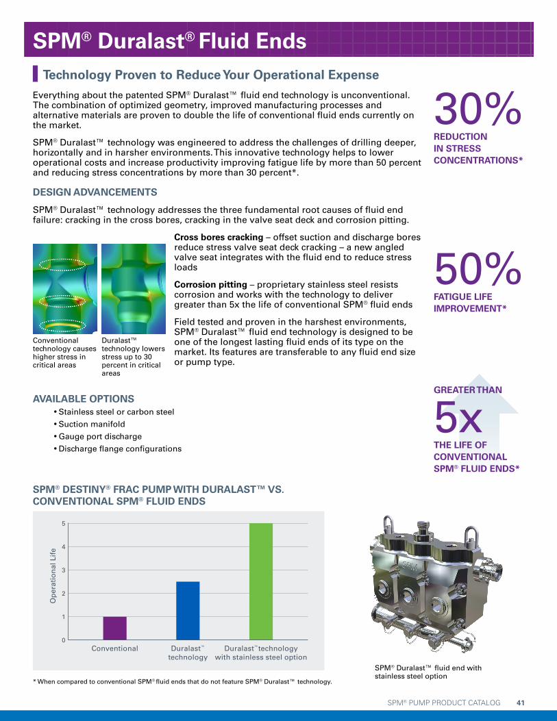
SPM® PUMP PRODUCT CATALOG 41
Everything about the patented SPM® Duralast™ fluid end technology is unconventional. The combination of optimized geometry, improved manufacturing processes and alternative materials are proven to double the life of conventional fluid ends currently on the market.
SPM® Duralast™ technology was engineered to address the challenges of drilling deeper, horizontally and in harsher environments. This innovative technology helps to lower operational costs and increase productivity improving fatigue life by more than 50 percent and reducing stress concentrations by more than 30 percent*.
DESIGN ADVANCEMENTS
SPM® Duralast™ technology addresses the three fundamental root causes of fluid end failure: cracking in the cross bores, cracking in the valve seat deck and corrosion pitting.
Cross bores cracking – offset suction and discharge bores reduce stress valve seat deck cracking – a new angled valve seat integrates with the fluid end to reduce stress loads
Corrosion pitting – proprietary stainless steel resists corrosion and works with the technology to deliver greater than 5x the life of conventional SPM® fluid ends
Field tested and proven in the harshest environments, SPM® Duralast™ fluid end technology is designed to be one of the longest lasting fluid ends of its type on the market. Its features are transferable to any fluid end size or pump type.
AVAILABLE OPTIONS •Stainless steel or carbon steel
•Suction manifold
•Gauge port discharge
•Discharge flange configurations
Technology Proven to Reduce Your Operational Expense
30%REDUCTION IN STRESS CONCENTRATIONS*
50%FATIGUE LIFEIMPROVEMENT*
GREATER THAN
5xTHE LIFE OF CONVENTIONALSPM® FLUID ENDS*
Conventional technology causes higher stress in critical areas
Duralast™ technology lowers stress up to 30 percent in critical areas
SPM® DESTINY® FRAC PUMP WITH DURALAST™ VS. CONVENTIONAL SPM® FLUID ENDS
0
1
2
3
4
5
Conventional Duralast™
technology Duralast™technology
with stainless steel option
Op
erat
ion
al L
ife
SPM® Duralast™ fluid end with stainless steel option
SPM® Duralast® Fluid Ends
* When compared to conventional SPM® fluid ends that do not feature SPM® Duralast™ technology.

Copyright © 2015, S.P.M. Flow Control, Inc.. All rights reserved. SPM, DESTINY and DURALAST are trademarks and/or registered trademarks of S.P.M. Flow Control, Inc.; WEIR and WEIR (logo) are trademarks and/or registered trademarks of Weir Engineering Services Ltd. Certain aspects of some of the products featured in this document are protected by patents pending and granted in the name of S.P.M. Flow Control, Inc.

SPM® PUMP PRODUCT CATALOG 43
WeirInAction.comWeirOilandGas.com
Document P/N: 2P140706
Release Date: 5/4/2015
Revision: IR | Date: 6/1/2015