puma vtr1216 series - doosan machinetools · the puma vtr1216 series is a 50-in. class vertical...
TRANSCRIPT

ver. EN 170720 SU
PUMA VTR1216series
PUMA VTR1216 seriesPUMA VTR1216PUMA VTR1216M
Large RAM-type Vertical Turning Center

0302 /
PUMA
VTR1216
series
PUMA VTR1216 seriesThe PUMA VTR1216 Series is a 50-in. class vertical RAM-type turning center offering the largest table turning diameter
of Ø1600mm (63.0 in.) in it’s class. It’s further extended machining range and enhanced stability are implemented
with a rigid and wide column structure.
Product Overview
Basic Information
Basic Structure
Detailed
Information
Options
Applications
Diagrams
Specifications
Customer Support
Service

0302 /
Full Stroke, Wide Machining Range
Single Wide Column Design provides wide machining range comprising Full X-axis (-700/+1000 mm (-27.6/+39.4 inch)) and Z-axis (1200 mm (47.2 inch)) of stroke.
World’s first RAM Tool Index System
For the first time in the world, this 2-axis machine tool features a quad-tool-holder-based ram tool index system that enables the use of 4 tools directly via the ram, dispensing with the need to use approach the ATC and thus enhancing productivity.
Improved Productivity with Powerful
Cutting Capacity
The high-strength Cr-Mo alloy steel RAM offers 8000kgf of tool clamping force, delivering durability and heavy cutting performance.
Contents
02 Product Overview
Basic Information
04 Basic Structure
Detailed Information
07 Standard / Optional Specifications
10 Applications
12 Diagrams
23 Machine / CNC Specifications
26 Customer Support Service
PUMA VTR1216 series

0504 /
PUMA
VTR1216
series
Product Overview
Basic Information
Basic Structure
Detailed
Information
Options
Applications
Diagrams
Specifications
Customer Support
Service
Basic Structure
Machining Area
The perfect thermally-symmetric bed and column guarantee powerful, stable, and long-term machining performance over wide machining area.
The largest machining area in it's class guarantees highest-level productivity and optimal flexibility in machining large workpieces.
Structure Designed for High Durability and Machining Stability
Equipped with a wide, one-piece type bed and wide column design, and supported by a large
capacity cooler, the PUMA VTR1216 Series guarantees long, powerful, and stable machining
performance.
* Series Composition PUMA VTR1216 PUMA VTR1216M (Milling Spindle)
Travel distance
X-axis
Z-axis
W-axis
-700 / +1000mmX-axis
1200mmZ-axis
800mmW-axis
(-27.6 / +39.4 inch)
(47.2 inch)
(31.5 inch)
Max. Turning Diameter (D)
D
H
Max. Turning Height (H)
Max. Loading Capacity
Ø1600mm
1250mm
8000kg
(63.0 inch)
(49.2 inch)
(17636.7 Ib)

0504 /
Provided with a high capacity cooler as standard, the perfectly thermally-symmetric spindle offers heavy and stable precision machining performance on a long-term basis.
Spindle
RAM Indexing
The tool holder’s 8 tons of clamping force supports heavy cutting, while Doosan’s unique ram indexing
technology and quad holder enable the use of 4 tools with 900 rotation without using the ATC, thereby
increasing productivity.
RAM Tool
The servo-driven tool magazine offers fast and accurate tool selection.
(60.3, 93.9 Hp)
ISO #50DIN 50 CAT 50
8ton
Tool Clamping Force
Chuck Size
50, 55inch Max. power
45, 70kW
Max. torque
20557, 31997N·m
Max. speed
400r/min
(15171.1, 23613.8 ft-lbs)

0706 /
PUMA
VTR1216
series
Product Overview
Basic Information
Basic Structure
ATC Tool Magazine
The servo-driven ATC tool magazine enables fast and accurate tool selection.
PUMA VTR1216M의 ATC
Max. Tool Storage Capacity
12, 24ea
Max. Tool Length
500mmPUMA VTR1216
16ea
(7 for turning / 8 for milling / 1 for cap)
34ea
(12 for turning / 21 for milling / 1 for cap)
PUMA VTR1216M
ATC Tool Magazine
12 ATC
•12 for turning
16 ATC• 7 for turning
• 8 for milling
• 1 for cap
34 ATC• 12 (1 ~ 24) for turning
• 21 (2 ~ 45) for milling
• 1 for cap
(19.7 inch)
Detailed
Information
Options
Applications
Diagrams
Specifications
Customer Support
Service

0706 /
Various optional features are available for specific work applications.
NO. Description Features PUMA VTR1216 PUMA VTR1216M
1 MAIN SPINDLE
A40/6000_45/37 kW (60.3/49.6 Hp) ● ●
2 A40HV/7000_70/45/37 kW (93.9/60.3/49.6 Hp) ○ ○
3Rotary Cylinder Type
NONE ● ●
4 LONG STROKE_YAST-250S ○ ○
5
CHUCK
CHUCK ADAPTER ONLY_D720 mm (28.3 inch) ○ ○
6 1250 mm (50 inch)_MANUAL 4-JAW ● ●
7 1400 mm (55 inch)_MANUAL 4-JAW ○ ○
8 1250 mm (50 inch)_COMBINATION ○ ○
9 1400 mm (55 inch)_COMBINATION ○ ○
10 1250 mm (50 inch)_POWER 3-JAW ○ ○
11 1400 mm (55 inch)_POWER 3-JAW ○ ○
12
Soft Top Jaws
NONE ● ●
13 MANUAL-4 EA ○ ○
14 MANUAL-8 EA ○ ○
15 COMBINATION-7 EA ○ ○
16 COMBINATION-14 EA ○ ○
17 POWER-3 EA ○ ○
18 POWER-6 EA ○ ○
19
Hard Top Jaws
NONE ● ●
20 MANUAL-4 EA ○ ○
21 COMBINATION-7 EA ○ ○
22 POWER-3 EA ○ ○
23
Tool Shank Type
BIG PLUS BT50 X ○
24 BIG PLUS CAT50 X ○
25 BIG PLUS DIN50 X ○
26
TOOL STORAGE CAPACITY
12 EA ● X
27 24 EA ○ X
28 16 EA (TURN-7 EA/MILL-8EA/CAP-1 EA) X ●
29 34 EA (TURN-12 EA/MILL-21EA/CAP-1 EA) X ○
30
Coolant pump for RAM
1.8 kW_0.7 Mpa_30 L/min (2.4 Hp_0.7 Mpa_30 L/min) ● ●
31 2.5 kW_1.0 Mpa_30 L/min (3.4 Hp_1.0 Mpa_30 L/min) ○ ○
32 1.5 kW_2.0 Mpa_28 L/min (2.0 Hp_2.0 Mpa_28 L/min) ○ ○
33 2.2 kW_7.0 Mpa_14 L/min (3.0 Hp_7.0 Mpa_14 L/min) ○ ○
34
Coolant options
High coolant interface ○ ○
35 Oil Skimmer (Belt type) ○ ○
36 Coolant flow switch ○ ○
37 Coolant level switch ○ ○
38
Chip Disposal Options
Rear chip conveyorHinged belt ○ ○
39 Magnetic scrapper ○ ○
40Chip bucket
Folklift 380L ○ ○
41 Rotation 380L ○ ○
42 Chip processing options Coolant gun ○ ○
43
Measurement & Automation
Automatic workpiece
measurementRMP60_RENISHAW ○ ○
44 Automatic front door and safety devices ○ ○
45 Tool Setter (Auto) ○ ○
46
Optional Accessories
Doosan tool load monitoring system ● ●
47 Linear scale (X / Z axis) ● ●
48 Auto power off ○ ○
49 Gravity axis drop prevention ● ●
50 Air conditioner ○ ○
Standard Optional X Not applicable
Standard/Option Specifications

0908 /
PUMA
VTR1216
series
Carbon steel Cast iron Aluminium
Long Short Needle Short Sludge Long Short Needle
Hinged belt type ○ △ X △ X ○ △ X
Magnetic Scrapper type X ○ ○ ○ ○ - - -
Product Overview
Detailed
Information
Options
Applications
Diagrams
Specifications
Customer Support
Service
Table Chuck option 6~11
Various types of table chucks are offered, including manual type and hydraulic type.
2-Stage Power Chuck
A hydraulic power chuck with 4 jaws which
are divided into 2 pairs each driven with a
2-stage hydraulic cylinder.
Manual Chuck Hydraulic ChuckManual & Hydraulic Combination Chuck
Various Options
Rear Exit Chip Conveyor option 38~39
Smooth chip disposal is guaranteed with the one-piece-type bed provided with chip discharge channels on both sides of the table
and rear exit dual chip conveyors.
○ : Suitable, △ : Possible, X : Not suitable
Material
Chip conveyor type
Long Short Needle Sludge
Basic Information
Basic Structure
0908 /
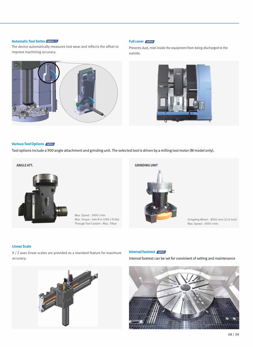
Linear Scale
X / Z axes linear scales are provided as a standard feature for maximum
accuracy.
Max. Speed : 3000 r/min
Max. Torque : 404 N·m (298.2 ft-lbs)
Through Tool Coolant : Max. 70barGringding Wheel : Ø305 mm (12.0 inch)
Max. Speed : 3000 r/min
ANGLE ATT. GRINDING UNIT
Various Tool Options
Tool options include a 900 angle attachment and grinding unit. The selected tool is driven by a milling tool motor (M model only).
Internal footrest
Internal footrest can be set for convinient of setting and maintenance
Full cover
Prevents dust, mist inside the equipment from being discharged to the
outside.
Automatic Tool Setter option 45 The device automatically measures tool wear and reflects the offset to
improve machining accuracy.

1110 /
PUMA
VTR1216
series
DOOSAN FANUC i
FANUC CNC has been optimized for DOOSAN's machine tools to maximize productivity.
• Axis jog feed• Spindle rotation
3.Portable MPG
Manual operation buttons
for easy maintenance and
setting.
1. Buttons
• Tool No. display - Simultaneous display
of tool No. & head tool
No.
2. Display
4.Hot keys for frequently used functions and a user-friendly button layout.
2
4
3
• Head tool rotation button
1
User friendly operation panel
Height adjustable 369 mm (14.5 inch)
Rotating
The operation panel can be raised, lowered, and swivelled for operating convenience.
Product Overview
Basic Information
Basic Structure
Detailed
Information
Options
Applications
Diagrams
Specifications
Customer Support
Service
1. Hot Key
2. Power Saving button for preserving the environment
3. Grouped layout by tools and coolant
4. Spindle and gear speed shift buttons
1 42
3

1110 /
Easy Operation Package
Doosan's unique Easy Operation Package (EOP) offers tool management function, peripheral device settings, operation, online help, and other
functionalities to maximize operational efficiency and user convenience.
- Tool position change and offset are displayed and set up.
- Easy compensation and prevention against deformation/
displacement by long-term operation, etc.
- Improved accuracy with thermal displacement compensation
- Real-time-based machine temperature monitoring
- Tool overload is monitored to prevent tool damage.
- Max. allowable load is set up to protect tools
- Real-time-based load monitoring
ATC Position Compensation
- Guidance for resetting alarms
- Management of alarm time and history
- Display of solenoid and sensor statuses and locations for
easier maintenance
Alarm Guidance Thermal Error Compensation (PUMA VTR1216M)
ATC Tool Load Monitoring
Automatic creation of cutting program EZ-Guide i screen
EZ-Guide i
Using the DOOSAN EZ-Guide i, users can create a cutting program for any desired shape, including patterns, by entering figures only.
Enter the dimensions of the shape.
O7000 (SAMPLE PROGRAM) ;
…
M3 S1500 ;
G0 X50. Y125. ;
G0 Z30. ;
G1040 T0.5 J3. H0.2 K0.5 … ;
G1020 H120. V50. U37. W68. … ;
G0 Z80. ;
M5 ;
A cutting program is automatically created with the entered values.

1312 /
PUMA
VTR1216
series
Product Overview
Basic Information
Basic Structure
Spindle Power – Torque Diagram
Spindle
PUMA VTR1216/M
PUMA VTR1216/M
Torq
ue :
N. m
(ft-
lbs)
Torq
ue :
N. m
(ft-
lbs)
Out
put :
kW
(Hp)
Out
put :
kW
(Hp)
Max. power
Max. power
Max. torque
Max. torque
45kW 20557N.m
10 (13.4)
100 (134.1)
10 (13.4)
100 (134.1)
1 10
100 (73.8)
10000 (7380.0)
400
1 10
400
21 55115
72 127115
109300
18.5 (24.8)
37.3 (50.0) 45 (60.3)
70 (93.9)
37 (49.6)30.8 (41.3)
22 (29.5)
S3 60%
S1, cont.
S3 60%S3 60%
S3 25%
S3 60% 45 (60.3)S3 60%S1, cont. 37 (49.6)
26 (34.9) 22 (29.5)
S1, cont.
S3 25%S3 25%
S1, cont.
S1, cont.
S3 60%
20557 (15171.1)
100 (73.8)
10000 (7380.0)
31977 (23599.0)S3 60%20557 (15171.1)S1, cont.16902 (12473.7)
25%5814 (4290.7)S3 60%3738 (2758.6)S1, cont.3073 (2267.9)
16902 (12473.7)
3738 (2758.6)
3073 (2267.9)
S1, cont.
21
10 (13.4)
100 (134.1)
10 (13.4)
100 (134.1)
1 10
100 (73.8)
10000 (7380.0)
400
1 10
400
21 55115
72 127115
109300
18.5 (24.8)
37.3 (50.0) 45 (60.3)
70 (93.9)
37 (49.6)30.8 (41.3)
22 (29.5)
S3 60%
S1, cont.
S3 60%S3 60%
S3 25%
S3 60% 45 (60.3)S3 60%S1, cont. 37 (49.6)
26 (34.9) 22 (29.5)
S1, cont.
S3 25%S3 25%
S1, cont.
S1, cont.
S3 60%
20557 (15171.1)
100 (73.8)
10000 (7380.0)
31977 (23599.0)S3 60%20557 (15171.1)S1, cont.16902 (12473.7)
25%5814 (4290.7)S3 60%3738 (2758.6)S1, cont.3073 (2267.9)
16902 (12473.7)
3738 (2758.6)
3073 (2267.9)
S1, cont.
21
Spindle speed : r/min
Spindle speed : r/minHV(High Voltage) CNC
70kW 31977N.m
(60.3 Hp)
(93.9 Hp)
(15171.1 ft-lbs)
(23599.0 ft-lbs)
Detailed
Information
Options
Applications
Diagrams
Specifications
Customer Support
Service

1312 /
PUMA VTR1216M
PUMA VTR1216M
10 (13.4)
100 (134.1)
10 (7.4)
100 (73.8)
1 10
S3 15% S3 60%
S1 cont.
S1 cont.
12.9 (17.3)
S3 25%15 (20.1)
11 (14.8)
7.5 (10.1)
18.5 (24.8)
3000
213
319
637 2550
1487
10 (7.4)
100 (73.8)
1
10 (13.4)
100 (134.1)
10
12.9 (17.3) S3 15% S3 60%
S1 cont.
S1 cont.
15 (20.1)11 (14.8)
7.5 (10.1)
S3 15%
S3 60%S1 cont.S1 cont.
674 (497.4)
449 (331.4)337 (248.7)330 (243.5)
S3 15%
S3 60%S1 cont.S1 cont.
449 (331.4)337 (248.7)330 (243.5)
S3 25%554 (408.9)674 (497.4)
3000
213
319
637 2550
Rotary Tool
Max power of live tool
15kW
Max power of live tool Max. torque
18.5kW 674N.m
Max. torque
674N.m
Spindle speed : r/min
Spindle speed : r/min
Torq
ue :
N. m
(ft-
lbs)
Torq
ue :
N. m
(ft-
lbs)
Out
put :
kW
(Hp)
Out
put :
kW
(Hp)
Max speed of live tool
3000r/min
10 (13.4)
100 (134.1)
10 (7.4)
100 (73.8)
1 10
S3 15% S3 60%
S1 cont.
S1 cont.
12.9 (17.3)
S3 25%15 (20.1)
11 (14.8)
7.5 (10.1)
18.5 (24.8)
3000
213
319
637 2550
1487
10 (7.4)
100 (73.8)
1
10 (13.4)
100 (134.1)
10
12.9 (17.3) S3 15% S3 60%
S1 cont.
S1 cont.
15 (20.1)11 (14.8)
7.5 (10.1)
S3 15%
S3 60%S1 cont.S1 cont.
674 (497.4)
449 (331.4)337 (248.7)330 (243.5)
S3 15%
S3 60%S1 cont.S1 cont.
449 (331.4)337 (248.7)330 (243.5)
S3 25%554 (408.9)674 (497.4)
3000
213
319
637 2550
Max speed of live tool
3000r/min
HV(High Voltage) CNC
(497.4 ft-lbs)
(497.4 ft-lbs)
(24.8 Hp)
(20.1 Hp)
Product Overview
Basic Information
Basic Structure
Detailed
Information
Options
Applications
Diagrams
Specifications
Customer Support
Service
1514 /
PUMA
VTR1216
series
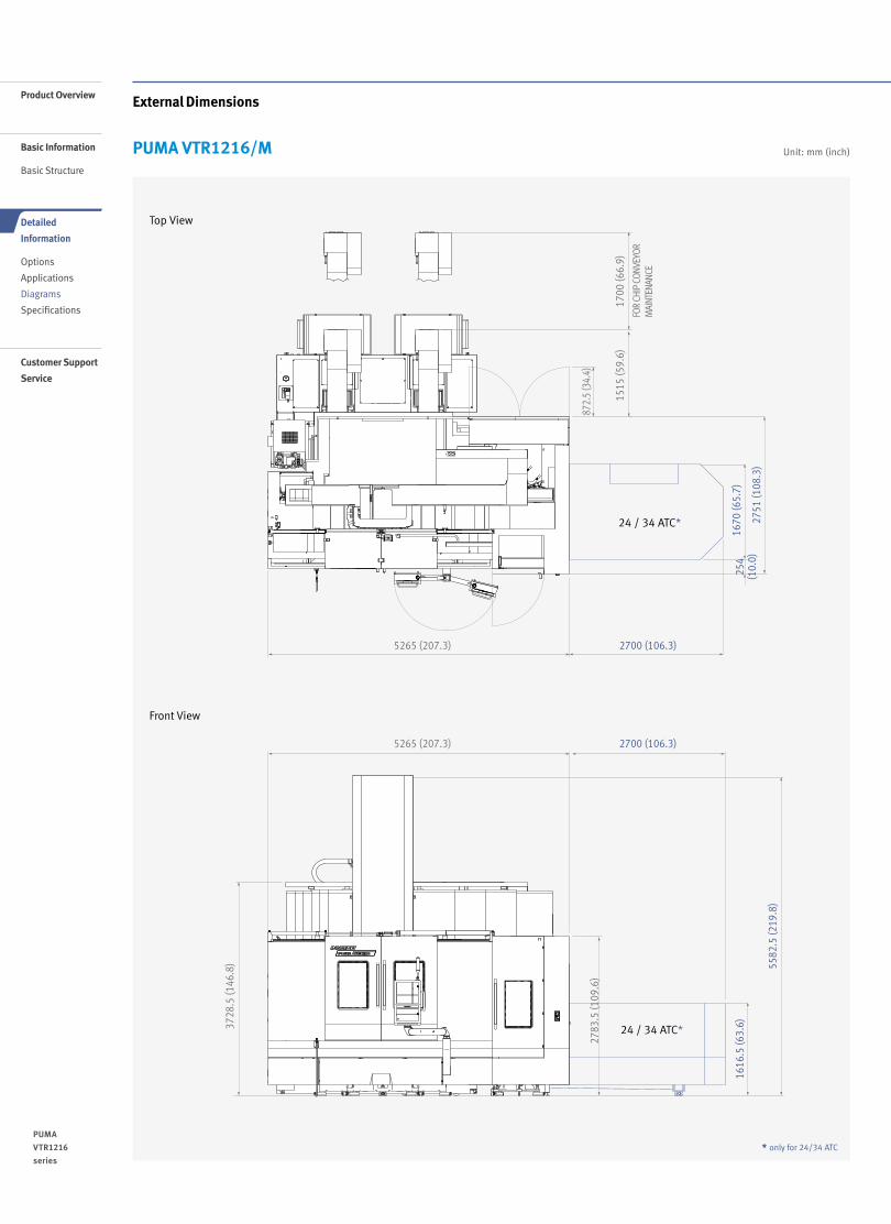
Top View
Front View
FOR
CHIP
CON
VEYO
RM
AINT
ENAN
CE
2751
(108
.3)
5582
.5 (2
19.8
)
2783
.5 (1
09.6
)
3728
.5 (1
46.8
)
1515
(59.
6)17
00 (6
6.9)
872.
5 (3
4.4)
5265 (207.3)
5265 (207.3)
2700 (106.3)
2700 (106.3)16
16.5
(63.
6)16
70 (6
5.7)
254
(10.
0)
24 / 34 ATC*
24 / 34 ATC*
* only for 24/34 ATC
External Dimensions
Unit: mm (inch)PUMA VTR1216/M
1514 /
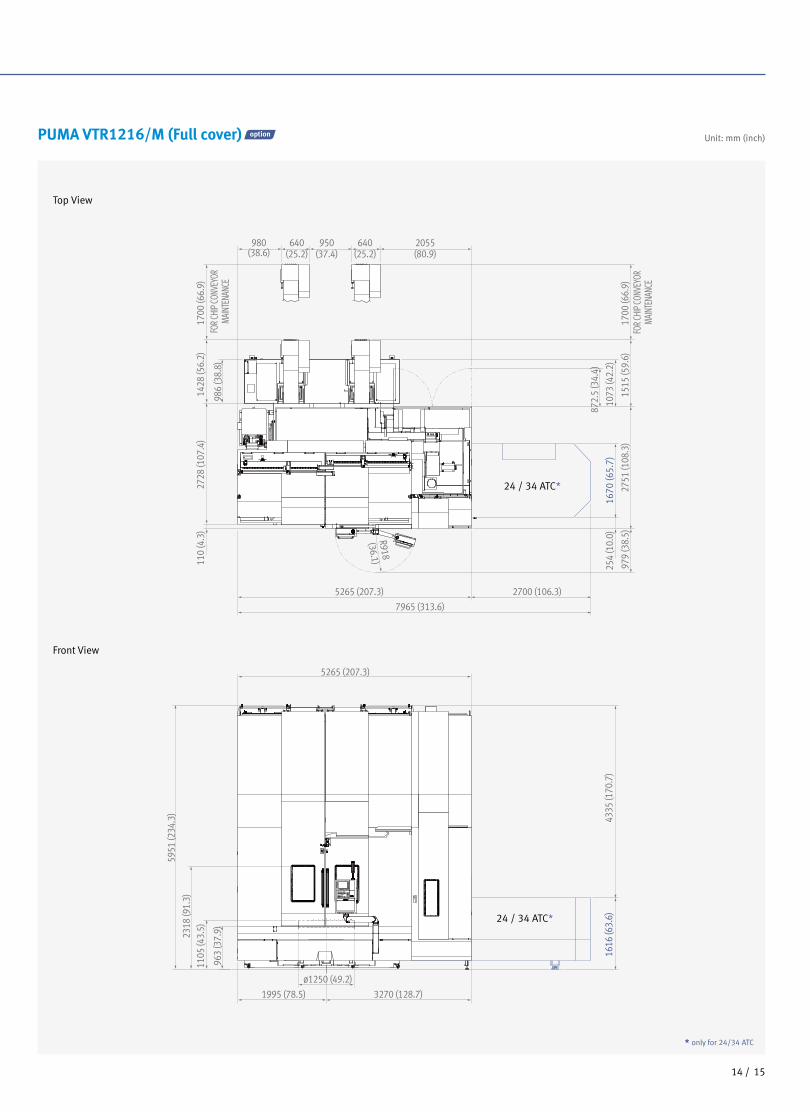
Unit: mm (inch)PUMA VTR1216/M (Full cover)
Top View
Front View
2728
(107
.4)
1428
(56.
2)
986
(38.
8)
1700
(66.
9)
980(38.6)
640(25.2)
950(37.4)
640(25.2)
2055(80.9)
2700 (106.3)5265 (207.3)
R918 (36.1)
5265 (207.3)
3270 (128.7)1995 (78.5)
ø1250 (49.2)
5951
(234
.3)
4335
(170
.7)
1616
(63.
6)
2318
(91.
3)11
05 (4
3.5)
963
(37.
9)
7965 (313.6)
FOR C
HIP C
ONVE
YOR
MAIN
TENA
NCE
1700
(66.
9)15
15 (5
9.6)
2751
(108
.3)
979
(38.
5)
254
(10.
0)16
70 (6
5.7)
1073
(42.
2)
872.
5 (3
4.4)
FOR C
HIP C
ONVE
YOR
MAIN
TENA
NCE
110
(4.3
)
24 / 34 ATC*
24 / 34 ATC*
* only for 24/34 ATC

Product Overview
Basic Information
Basic Structure
Tooling System
PUMA VTR1216/M
Detailed
Information
Options
Applications
Diagrams
Specifications
Customer Support
Service
1716 /
PUMA
VTR1216
series
Unit: mm (inch)PUMA VTR1216M
BASE TOOL HOLDER
ID TOOLHOLDER
TTC QUAD TOOL HOLDER
BORING TOOL
HOLDER
HANDLING JIG FOR HOLDER
CAPTO C6 / C8 QUAD
TOOL HOLDER
CAPTO C6 / C8 OD-FACE
HOLDER
CAPTO C6 / C8 DUAL OD
HOLDER
CAPTO C6 / C8 DUAL
FACE HOLDER
CAPTO C6 / C8 DUAL
ID HOLDER
RMP60 PROBE
SPECIAL TOOLBY
CUSTOMER
ø100(4")BORING BAR
CAPTO C6 / C8QUAD
CAPTO C6 / C8 DUAL
CAPTO C6 / C8CAPTO C6 / C8 DUAL
CAPTO C6 / C8DUAL
ø100-ø50(ø4"-ø2")SLEEVE
ø100-ø63(ø4"-ø2 )SLEEVE
12"
SQ32 (SQ1 CW / CCW
14 )"
QUAD TOOLHOLDER
SQ32 (SQ1 CW / CCW
14 )" SQ32 (SQ1
CW / CCW
14 )"
Milling cap
RMP60PROBE
STOPPER BLOCK FOR ANGLE TOOL
90-ANGLE TOOLTTC
90-ANGLE TOOLDUAL
90-ANGLE HEADHIGH TORQUE TTC
GRINDINGATTACHEMENT
404 N.m (298.2 ft-lbs)3000 r/min
Diameter305 mm (12.0 inch)
BT50-BIG PLUS
CAT50-BIG PLUS
DIN50-BIG PLUS
Unit: mm (inch)

1716 /
BASE TOOL HOLDER QUAD TOOL HOLDER
ID TOOL HOLDER BORING TOOL HOLDER
RMP60 PROBE CAPTO-C8 QUAD TOOL HOLDER
Tooling Attachment
PUMA VTR1216/M
ø255 (10.0)
60 (2.4)
110(4.3)
160 (6.3) 160 (6.3)
110(4.3)
60 (2.4)
79.5
(3.1
)23
3.5
(9.2
)
50 (2
.0)
251
(9.9
)
251
(9.9
)
95 (3.7
)
32 (1.3
) 118.
5(4
.7)
420
(16.
5)
420
(16.
5)46
.5(1
.8)
79.5
(3.1
)
40 (1.6
)86 (3.4
)
79.5
(3.1
)
122(4.8)
87 87122(4.8)
32(1.3)
32(1.3)
ø255 (10.0)
ø255 (10.0)
32(1.3)
32(1.3)
32(1.3)
32(1.3)
17 (0.7
)86 (3.4
)19
5(7
.7)
40 (1.6
)86 (3.4
)
ø255 (10.0)
ø255 (10.0)
ø63(2.5)
ø145 (5.7)
32(1.3)
32 (1.3
)
32(1.3)
ø114(4.5)
ø100 (3.9)
ø174 (6.9)
ø174(6.9)
ø174(6.9)
ø150 (5.9)
150
(5.9
)
195
(7.7
)
126
(5.0
)14
5.6
(5.7
)29 (1.1
)57 (2.2
)
271.
6(1
0.7)
86 (3.4
)
46.5
(1.8
)79
.5(3
.1)
ø174 (6.9)
45˚
36.22˚ 36.22˚
22.5˚
79.5
(3.1
)
86 (3.4
)
6.5
(0.3
)
ø255 (10.0)
ø150ø176
ø254 (10.0)87
(3.4)87
(3.4)
Unit: mm (inch)

Product Overview
Basic Information
Basic Structure
Detailed
Information
Options
Applications
Diagrams
Specifications
Customer Support
Service
1918 /
PUMA
VTR1216
series
CAPTO-C8 OD-FACE HOLDER CAPTO-C8 DUAL FACE HOLDER
CAPTO-C8 DUAL-OD HOLDER MILLING CAP
90-ANGLE TOOL TTC 90-ANGLE TOOL DUAL
Tooling Attachment
PUMA VTR1216/M10 (0.4
)
55 (2.2
)19
5(7
.7)
180
(7.1
)55 (2.2
)10
.5(0
.4)
210
(8.3
)55 (2.2
)10
.5(0
.4)
40 (1.6
)22
5(8
.9)
55 (2.2
)
40 (1.6
)
19 (0.7
)
ø120(4.7)
115(4.5)
80.5(3.2)
92(3.6)
145 (5.7)
80.5(3.2)
ø120(4.7)
115(4.5)
100(3.9)
90(3.5)
145 (5.7)
30(1.2)
8(0.3)
109
(1.3
)46
.5(1
.8)
79.5
(3.1
)
126
(5.0
)10
9(4
.3)
79.5
(3.1
)11
6.5
(4.6
)91 (3.6
)
134(5.3)
50(2.0)
85(3.3)
85(3.3)
50(2.0)
174 (6.9)
ø255 (10.0)
ø255 (10.0)
139 (5.5)134(5.3)
174 (6.9)
139 (5.5)
236
(9.3
)50 (2.0
)
67(2.6)
110(4.3)
85(3.3)
50(2.0)
174(6.9)
67(2.6)
ø255 (10.0)
79.5
(3.1
)41
.5(1
.6)
54 (2.1
)50 (2.0
) 117
(4.6
)12
1(4
.8)
13 (0.5
)
29.5
(1.2
)
51.5
(2.0
)
29.5
(1.2
)ø260 (10.2)
ø18(0.7)
ø260 (10.2)
115(4.5)
65
115
(4.5
)
Unit: mm (inch)

1918 /
90 angle high torque TTC
Grinding attachment
PUMA VTR1216/M
ø255 (10.0)
MAS BT50-BIG PLUS
MAS BT50-BIG PLUS 95 (3.7) 188.5 (7.4)349.5 (13.8)
66 (2.6)
343.
8 (1
3.5)
94
(3.7
)
437.
8 (1
7.2)
84.5
(3.3
)
79.5
(3.1
)
ø255 (10.0)
MAS BT50-BIG PLUS
GRINDING WHEEL
364
(14.
3)
276
(10.
9)70 (2.8
)18 (0.7
)
292.
5 (1
1.5)
38 (1.5
)84
.5(3
.3)
ø180 (7.1)
ø127.5 (5.0)ø200 (7.9)
ø305 (12.0)
132 (5.2) 170 (6.7)
Tooling Attachment
Unit: mm (inch)

Product Overview
Basic Information
Basic Structure
Detailed
Information
Options
Applications
Diagrams
Specifications
Customer Support
Service
2120 /
PUMA
VTR1216
series
Working Range
PUMA VTR1216/M
(-) 700 (27.6)(X-axis stroke)
(+) 1580 (62.2) (X-axis stroke)
1080 (42.5) (ATS Position)
172
(6.8)
660
(26.0)
1460
(57.5
)19
8.5 (7.8)
800 (
31.5)
(W
-axi
s st
roke
)
1200
(47.2
) (Z-a
xis
stro
ke)
800 (
31.5)
(W
-axis
strok
e)46
1.5 (18
.2)
Ø1250 (49.2) (Option : Ø1400 (55.1))
Ø1600 (63.0)(Max. Turning Diameter)
Ø720 (28.3)
373.5
(14.7)
358.5
(14.1)
107.5 (4.2)
90.5
(3.6)
122(4.8)
122(4.8)
32 (1.3)32 (1.
3)
41 (1.6)
41 (1.6)
(-) 700 (27.6)(X-axis stroke)
(-) 700 (27.6)(X-axis stroke)
(-) 700 (27.6)(X-axis stroke)
(-) 700 (27.6)(X-axis stroke)
(+) 1580 (62.2) (X-axis stroke)
(+) 1580 (62.2) (X-axis stroke)
(+) 1580 (62.2) (X-axis stroke)1080 (42.5) (ATS Position)
1080 (42.5) (ATS Position)
1080 (42.5) (ATS Position)
(+) 1580 (62.2) (X-axis stroke)1080 (42.5) (ATS Position)
172
(6.8)
660
(26.
0)
1460
(57.
5)14
60 (5
7.5)
1460
(57.
5)
61.5
(2.4)
321.5
(12.7)
38.5
(1.5)
800 (
31.5)
(W-ax
is stro
ke)80
0 (31.5
) (W
-axis
stro
ke)
378.5
(14.9)
71.5 (
2.8)
800 (
31.5)
(W-a
xis st
roke
) 62
8.5 (2
4.7)
338.5
(13.3)
Ø150(5.9)
Ø195
(7.7)
213.5 (8.4)
373.5
(14.7
)24
3.5 (9.6) 53
3.5 (2
1.0)
36.5
(1.4)
367 (
14.4)
Ø100(3.9)
107.5
(4.2)
46.5
(1.8)
800
(31.
5)
(W-a
xis st
roke
)17
2(6.
8)66
0 (2
6.0)
800
(31.
5)
(W-a
xis st
roke
)
172
(6.8)
660
(26.
0)80
0 (3
1.5)
(W
-axis
stro
ke)
660
(26.
0)
1460
(57.
5)54
6.5 (2
1.5)
286.5
(11.3)
113.5 (4.5)
8 (0.3
)
800
(31.
5)
(W-a
xis st
roke
)
800
(31.
5)
(W-a
xis st
roke
)
1200
(47.2
)(Z-a
xis st
roke
)
1200
(47.2
) (Z-a
xis st
roke
) 12
00 (4
7.2) (Z
-axis
stro
ke)
281.5
(11.1)
21.5
(0.8)
1200
(47.2
) (Z-a
xis st
roke
) 22
8.5 (9.0)
31.5
(1.2)
1100
(43.3
) (Max
. Turn
ing He
ight)
1250
(49.2
) (Max
. Turn
ing He
ight)
1250
(49.2
) (Max
. Turn
ing He
ight)
178.5 (7.0)
905.
5 (3
5.6)
(Max
. Tur
ning
Heig
ht)
Chuck 50 inch (Option 55 inch) Chuck 50 inch (Option 55 inch)
Chuck 50 inch (Option 55 inch) Chuck 50 inch (Option 55 inch)
Ø1250 (49.2) (Option : Ø1400 (55.1))
Ø1600 (63.0) (Max. Turning Diameter)
Ø720 (28.3)
Ø1250 (49.2) (Option : Ø1400 (55.1))
Ø1600 (63.0) (Max. Turning Diameter)
Ø720 (28.3)
Ø1250 (49.2) (Option : Ø1400 (55.1))
Ø1600 (63.0) (Max. Turning Diameter)
Ø720 (28.3)
Ø210 (8.3)
Ø210 (8.3)
10.5
(0.4)
373.5
(14.7
)
107.5 (4.2)
438.5
(17.3)
32
(1.3)
420 (
16.5)
Ø145 (5.7)
Ø145 (5.7)
Chuck 50 inch (Option 55 inch)
Ø1250 (49.2) (Option : Ø1400 (55.1))
Ø1600 (63.0) (Max. Turning Diameter)
Ø720 (28.3)
Max. 300(11.8)
167
(6.6)
83 (3
.3)
367 (
14.4)
283.5
(11.2)
615 (
24.2)
8 (0.3)
1253
.5 (49
.4) (M
ax. Tu
rning
Heigh
t)
(-) 700 (27.6)(X-axis stroke)
(+) 1580 (62.2) (X-axis stroke)
1080 (42.5) (ATS Position)
172
(6.8)
660
(26.0)
1460
(57.5
)19
8.5 (7.8)
800 (
31.5)
(W
-axi
s st
roke
)
1200
(47.2
) (Z-a
xis
stro
ke)
800 (
31.5)
(W
-axis
strok
e)46
1.5 (18
.2)
Ø1250 (49.2) (Option : Ø1400 (55.1))
Ø1600 (63.0)(Max. Turning Diameter)
Ø720 (28.3)
373.5
(14.7)
358.5
(14.1)
107.5 (4.2)
90.5
(3.6)
122(4.8)
122(4.8)
32 (1.3)32 (1.
3)
41 (1.6)
41 (1.6)
(-) 700 (27.6)(X-axis stroke)
(-) 700 (27.6)(X-axis stroke)
(-) 700 (27.6)(X-axis stroke)
(-) 700 (27.6)(X-axis stroke)
(+) 1580 (62.2) (X-axis stroke)
(+) 1580 (62.2) (X-axis stroke)
(+) 1580 (62.2) (X-axis stroke)1080 (42.5) (ATS Position)
1080 (42.5) (ATS Position)
1080 (42.5) (ATS Position)
(+) 1580 (62.2) (X-axis stroke)1080 (42.5) (ATS Position)
172
(6.8)
660
(26.
0)
1460
(57.
5)14
60 (5
7.5)
1460
(57.
5)
61.5
(2.4)
321.5
(12.7)
38.5
(1.5)
800 (
31.5)
(W-ax
is stro
ke)80
0 (31.5
) (W
-axis
stro
ke)
378.5
(14.9)
71.5 (
2.8)
800 (
31.5)
(W-a
xis st
roke
) 62
8.5 (2
4.7)
338.5
(13.3)
Ø150(5.9)
Ø195
(7.7)
213.5 (8.4)
373.5
(14.7
)24
3.5 (9.6) 53
3.5 (2
1.0)
36.5
(1.4)
367 (
14.4)
Ø100(3.9)
107.5
(4.2)
46.5
(1.8)
800
(31.
5)
(W-a
xis st
roke
)17
2(6.
8)66
0 (2
6.0)
800
(31.
5)
(W-a
xis st
roke
)
172
(6.8)
660
(26.
0)80
0 (3
1.5)
(W
-axis
stro
ke)
660
(26.
0)
1460
(57.
5)54
6.5 (2
1.5)
286.5
(11.3)
113.5 (4.5)
8 (0.3
)
800
(31.
5)
(W-a
xis st
roke
)
800
(31.
5)
(W-a
xis st
roke
)
1200
(47.2
)(Z-a
xis st
roke
)
1200
(47.2
) (Z-a
xis st
roke
) 12
00 (4
7.2) (Z
-axis
stro
ke)
281.5
(11.1)
21.5
(0.8)
1200
(47.2
) (Z-a
xis st
roke
) 22
8.5 (9.0)
31.5
(1.2)
1100
(43.3
) (Max
. Turn
ing He
ight)
1250
(49.2
) (Max
. Turn
ing He
ight)
1250
(49.2
) (Max
. Turn
ing He
ight)
178.5 (7.0)
905.
5 (3
5.6)
(Max
. Tur
ning
Heig
ht)
Chuck 50 inch (Option 55 inch) Chuck 50 inch (Option 55 inch)
Chuck 50 inch (Option 55 inch) Chuck 50 inch (Option 55 inch)
Ø1250 (49.2) (Option : Ø1400 (55.1))
Ø1600 (63.0) (Max. Turning Diameter)
Ø720 (28.3)
Ø1250 (49.2) (Option : Ø1400 (55.1))
Ø1600 (63.0) (Max. Turning Diameter)
Ø720 (28.3)
Ø1250 (49.2) (Option : Ø1400 (55.1))
Ø1600 (63.0) (Max. Turning Diameter)
Ø720 (28.3)
Ø210 (8.3)
Ø210 (8.3)
10.5
(0.4)
373.5
(14.7
)
107.5 (4.2)
438.5
(17.3)
32
(1.3)
420 (
16.5)
Ø145 (5.7)
Ø145 (5.7)
Chuck 50 inch (Option 55 inch)
Ø1250 (49.2) (Option : Ø1400 (55.1))
Ø1600 (63.0) (Max. Turning Diameter)
Ø720 (28.3)
Max. 300(11.8)
167
(6.6)
83 (3
.3)
367 (
14.4)
283.5
(11.2)
615 (
24.2)
8 (0.3)
1253
.5 (49
.4) (M
ax. Tu
rning
Heigh
t)
Quad Tool Holder
ID Holder
Unit: mm (inch)
2120 /
(-) 700 (27.6)(X-axis stroke)
(+) 1580 (62.2) (X-axis stroke)
1080 (42.5) (ATS Position)
172
(6.8)
660
(26.0)
1460
(57.5
)19
8.5 (7.8)
800 (
31.5)
(W
-axi
s st
roke
)
1200
(47.2
) (Z-a
xis
stro
ke)
800 (
31.5)
(W
-axis
strok
e)46
1.5 (18
.2)
Ø1250 (49.2) (Option : Ø1400 (55.1))
Ø1600 (63.0)(Max. Turning Diameter)
Ø720 (28.3)
373.5
(14.7)
358.5
(14.1)
107.5 (4.2)
90.5
(3.6)
122(4.8)
122(4.8)
32 (1.3)32 (1.
3)
41 (1.6)
41 (1.6)
(-) 700 (27.6)(X-axis stroke)
(-) 700 (27.6)(X-axis stroke)
(-) 700 (27.6)(X-axis stroke)
(-) 700 (27.6)(X-axis stroke)
(+) 1580 (62.2) (X-axis stroke)
(+) 1580 (62.2) (X-axis stroke)
(+) 1580 (62.2) (X-axis stroke)1080 (42.5) (ATS Position)
1080 (42.5) (ATS Position)
1080 (42.5) (ATS Position)
(+) 1580 (62.2) (X-axis stroke)1080 (42.5) (ATS Position)
172
(6.8)
660
(26.
0)
1460
(57.
5)14
60 (5
7.5)
1460
(57.
5)
61.5
(2.4)
321.5
(12.7)
38.5
(1.5)
800 (
31.5)
(W-ax
is stro
ke)80
0 (31.5
) (W
-axis
stro
ke)
378.5
(14.9)
71.5 (
2.8)
800 (
31.5)
(W-a
xis st
roke
) 62
8.5 (2
4.7)
338.5
(13.3)
Ø150(5.9)
Ø195
(7.7)
213.5 (8.4)
373.5
(14.7
)24
3.5 (9.6) 53
3.5 (2
1.0)
36.5
(1.4)
367 (
14.4)
Ø100(3.9)
107.5
(4.2)
46.5
(1.8)
800
(31.
5)
(W-a
xis st
roke
)17
2(6.
8)66
0 (2
6.0)
800
(31.
5)
(W-a
xis st
roke
)
172
(6.8)
660
(26.
0)80
0 (3
1.5)
(W
-axis
stro
ke)
660
(26.
0)
1460
(57.
5)54
6.5 (2
1.5)
286.5
(11.3)
113.5 (4.5)
8 (0.3
)
800
(31.
5)
(W-a
xis st
roke
)
800
(31.
5)
(W-a
xis st
roke
)
1200
(47.2
)(Z-a
xis st
roke
)
1200
(47.2
) (Z-a
xis st
roke
) 12
00 (4
7.2) (Z
-axis
stro
ke)
281.5
(11.1)
21.5
(0.8)
1200
(47.2
) (Z-a
xis st
roke
) 22
8.5 (9.0)
31.5
(1.2)
1100
(43.3
) (Max
. Turn
ing He
ight)
1250
(49.2
) (Max
. Turn
ing He
ight)
1250
(49.2
) (Max
. Turn
ing He
ight)
178.5 (7.0)
905.
5 (3
5.6)
(Max
. Tur
ning
Heig
ht)
Chuck 50 inch (Option 55 inch) Chuck 50 inch (Option 55 inch)
Chuck 50 inch (Option 55 inch) Chuck 50 inch (Option 55 inch)
Ø1250 (49.2) (Option : Ø1400 (55.1))
Ø1600 (63.0) (Max. Turning Diameter)
Ø720 (28.3)
Ø1250 (49.2) (Option : Ø1400 (55.1))
Ø1600 (63.0) (Max. Turning Diameter)
Ø720 (28.3)
Ø1250 (49.2) (Option : Ø1400 (55.1))
Ø1600 (63.0) (Max. Turning Diameter)
Ø720 (28.3)
Ø210 (8.3)
Ø210 (8.3)
10.5
(0.4)
373.5
(14.7
)
107.5 (4.2)
438.5
(17.3)
32
(1.3)
420 (
16.5)
Ø145 (5.7)
Ø145 (5.7)
Chuck 50 inch (Option 55 inch)
Ø1250 (49.2) (Option : Ø1400 (55.1))
Ø1600 (63.0) (Max. Turning Diameter)
Ø720 (28.3)
Max. 300(11.8)
167
(6.6)
83 (3
.3)
367 (
14.4)
283.5
(11.2)
615 (
24.2)
8 (0.3)
1253
.5 (49
.4) (M
ax. Tu
rning
Heigh
t)
(-) 700 (27.6)(X-axis stroke)
(+) 1580 (62.2) (X-axis stroke)
1080 (42.5) (ATS Position)
172
(6.8)
660
(26.0)
1460
(57.5
)19
8.5 (7.8)
800 (
31.5)
(W
-axi
s st
roke
)
1200
(47.2
) (Z-a
xis
stro
ke)
800 (
31.5)
(W
-axis
strok
e)46
1.5 (18
.2)
Ø1250 (49.2) (Option : Ø1400 (55.1))
Ø1600 (63.0)(Max. Turning Diameter)
Ø720 (28.3)
373.5
(14.7)
358.5
(14.1)
107.5 (4.2)
90.5
(3.6)
122(4.8)
122(4.8)
32 (1.3)32 (1.
3)
41 (1.6)
41 (1.6)
(-) 700 (27.6)(X-axis stroke)
(-) 700 (27.6)(X-axis stroke)
(-) 700 (27.6)(X-axis stroke)
(-) 700 (27.6)(X-axis stroke)
(+) 1580 (62.2) (X-axis stroke)
(+) 1580 (62.2) (X-axis stroke)
(+) 1580 (62.2) (X-axis stroke)1080 (42.5) (ATS Position)
1080 (42.5) (ATS Position)
1080 (42.5) (ATS Position)
(+) 1580 (62.2) (X-axis stroke)1080 (42.5) (ATS Position)
172
(6.8)
660
(26.
0)
1460
(57.
5)14
60 (5
7.5)
1460
(57.
5)
61.5
(2.4)
321.5
(12.7)
38.5
(1.5)
800 (
31.5)
(W-ax
is stro
ke)80
0 (31.5
) (W
-axis
stro
ke)
378.5
(14.9)
71.5 (
2.8)
800 (
31.5)
(W-a
xis st
roke
) 62
8.5 (2
4.7)
338.5
(13.3)
Ø150(5.9)
Ø195
(7.7)
213.5 (8.4)
373.5
(14.7
)24
3.5 (9.6) 53
3.5 (2
1.0)
36.5
(1.4)
367 (
14.4)
Ø100(3.9)
107.5
(4.2)
46.5
(1.8)
800
(31.
5)
(W-a
xis st
roke
)17
2(6.
8)66
0 (2
6.0)
800
(31.
5)
(W-a
xis st
roke
)
172
(6.8)
660
(26.
0)80
0 (3
1.5)
(W
-axis
stro
ke)
660
(26.
0)
1460
(57.
5)54
6.5 (2
1.5)
286.5
(11.3)
113.5 (4.5)
8 (0.3
)
800
(31.
5)
(W-a
xis st
roke
)
800
(31.
5)
(W-a
xis st
roke
)
1200
(47.2
)(Z-a
xis st
roke
)
1200
(47.2
) (Z-a
xis st
roke
) 12
00 (4
7.2) (Z
-axis
stro
ke)
281.5
(11.1)
21.5
(0.8)
1200
(47.2
) (Z-a
xis st
roke
) 22
8.5 (9.0)
31.5
(1.2)
1100
(43.3
) (Max
. Turn
ing He
ight)
1250
(49.2
) (Max
. Turn
ing He
ight)
1250
(49.2
) (Max
. Turn
ing He
ight)
178.5 (7.0)
905.
5 (3
5.6)
(Max
. Tur
ning
Heig
ht)
Chuck 50 inch (Option 55 inch) Chuck 50 inch (Option 55 inch)
Chuck 50 inch (Option 55 inch) Chuck 50 inch (Option 55 inch)
Ø1250 (49.2) (Option : Ø1400 (55.1))
Ø1600 (63.0) (Max. Turning Diameter)
Ø720 (28.3)
Ø1250 (49.2) (Option : Ø1400 (55.1))
Ø1600 (63.0) (Max. Turning Diameter)
Ø720 (28.3)
Ø1250 (49.2) (Option : Ø1400 (55.1))
Ø1600 (63.0) (Max. Turning Diameter)
Ø720 (28.3)
Ø210 (8.3)
Ø210 (8.3)
10.5
(0.4)
373.5
(14.7
)
107.5 (4.2)
438.5
(17.3)
32
(1.3)
420 (
16.5)
Ø145 (5.7)
Ø145 (5.7)
Chuck 50 inch (Option 55 inch)
Ø1250 (49.2) (Option : Ø1400 (55.1))
Ø1600 (63.0) (Max. Turning Diameter)
Ø720 (28.3)
Max. 300(11.8)
167
(6.6)
83 (3
.3)
367 (
14.4)
283.5
(11.2)
615 (
24.2)
8 (0.3)
1253
.5 (49
.4) (M
ax. Tu
rning
Heigh
t)
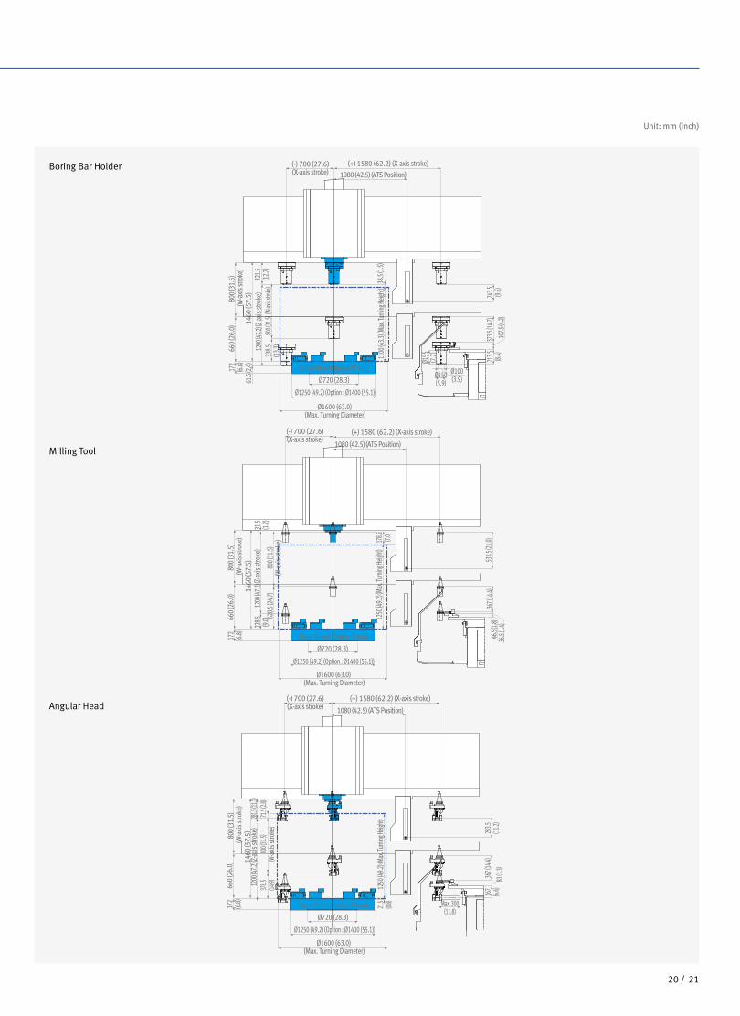
Milling Tool
Boring Bar Holder
Angular Head
Unit: mm (inch)

Product Overview
Basic Information
Basic Structure
Detailed
Information
Options
Applications
Diagrams
Specifications
Customer Support
Service
2322 /
PUMA
VTR1216
series
Tool Interference Diagram
PUMA VTR1216 (12-ATC)
PUMA VTR1216 (15-ATC) Unit: mm (inch)
30
1345
.36
1345
.36
130
(5.1
)
660(26.0)
260 (10.2)
Max
22.5
260 (10.2)
Max
260 (10.2)
Max
660(26.0)
Max. RAM tool size
ø255 (10.0)244 (9.6)
166
(6.5
)50
0 (1
9.7)
388.
5 (1
5.3)
270
(10.
6)
86 (3.4
) STANDARD TOOL
70 (2.8)
EXTEND TOOLUSE SPECIAL ATS
230(9.1)
350
(13.
8)25
0 (9
.8)
120
(4.7
)
290(11.4)
ø260 (10.2)USE SPECIAL ATS
Max. 330 (13.0)
Max. RAM tool size
Unit: mm (inch)

2322 /
Machine Specifications
PUMA VTR1216 series
Description Unit PUMA VTR1216 PUMA VTR1216M
Capacity Swing over bed mm (inch) 1700 (66.9)
Recommended turning diameter mm (inch) 1250 (49.2)
Max. turning diameter mm (inch) 1600 (63.0)
Max. turning height mm (inch) 1250 (49.2)
Max. allowable workpiece weight kg (lb) 8000 (10,728.0)
Travel
Travel distance
X-axis mm (inch) -700 ~ 1000 (-27.6 ~ 39.4)
Z-axis mm (inch) 1200 (47.2)
W-axis mm (inch) 800 (200 x 4step) (31.5 (7.9 x 4step))
Feedrate
Rapid traverse
X-axis m/min 12
Z-axis m/min 10
Spindle Spindle Max. speed r/min 400
Spindle Max. power (30min/cont.) kW (Hp)45/37 {HV** : 70(S3 25%)/45/37}*
(60.3/49.6 {HV** : 93.9(S3 25%)/60.3/49.6}*)
Spindle Max. torque N·m (ft-lbs)20557 {HV** : 31997}*
(15171.1 {HV** : 23613.8}*)
C-axis min.indexing angle deg - 0.001
Tool
magazineNo.of tool gripper ea 12 / 24 15 / 33
Magazine indexing time(1st) sec 5.0
Max.tool length mm (inch) 500 (19.7)
Tooling OD/Face tool mm (inch) 32 (1.3)
ID Tool size mm (inch) 32 (1.3)
Boring Bar diameter mm (inch) 100 (3.9)
Tool clamping force kNTurning tool : 78.5
Milling too : 23.5
RAM RAM size mm (inch) 260 x 260 (10.2 x 10.2)
Milling
spindleSpindle Max. speed r/min - 3000
Spindle Max. power (30min / cont.) kW (Hp) -18.5/15/11 {HV** : 15/11}*
(24.8/20.1/14.8 {HV** : 20.1/14.8}*)
Spindle Max. torque N·m (ft-lbs) - 674 (497.4)
Power
sourcePower consumption kva 120 120
Machine
dimensionsLength x width mm (inch) 5265 x 3824 (207.3 x 150.6)
Height mm (inch) 5583 (219.8)
Weight kg (lb) 29500 (65035.4) 30000 (66137.7)
Control CNC system DOOSAN-FANUC i
* { } : option ** HV : High voltage CNC

2524 /
PUMA
VTR1216
series
Product Overview
Basic Information
Basic StructureDOOSAN FANUC i
CNC Specifications
NO. Division Item Spec. PUMA VTR1216 PUMA VTR1216M
1
Controlled axis
Simultaneously controlled axes 2 axes(X, Z) 3 axes(X, Z, C)
2 Cs contouring control X ●
3 Torque control ● ●
4 HRV2 control ● ●
5 Inch/metric conversion ● ●
6 Stored stroke check 1 ● ●
7 Stored stroke check 2, 3 ● ●
8 Stored limit check before move ● ●
9 Chamfering on/off ● ●
10Unexpected disturbance torque detection function
● ●
11 Position switch ● ●
12
Operation
DNC operationIncluded in RS232C interface.
● ●
13 DNC operation with memory card ● ●
14 Tool retract and recover ○ ○
15 Wrong operation prevention ● ●
16 Dry run ● ●
17 Single block ● ●
18 Reference position shift ● ●
19 Handle interruption ○ ○
20 Incremental feed x1,x10,x100 ● ●
21 Manual handle retrace ○ ○
22 Active block cancel ○ ○
23
Interpolation functions
Nano interpolation ● ●
24 Linear interpolation ● ●
25 Circular interpolation ● ●
26 Polar coordinate interpolation X ●
27 Cylindrical interpolation X ●
28 Helical interpolation X ○
29 Thread cutting, synchronous cutting ● ●
30 Multi threading ● ●
31 Thread cutting retract ● ●
32 Continuous threading ● ●
33 Variable lead thread cutting ● ●
34 Circular thread cutting ○ ○
35 Polygon machining with two spindles X ●
36 High-speed skipInput signal is 8 points.
○ ○
37 2nd reference position return G30 ● ●
38 3rd/4th reference position return ● ●
39
Feed function
Override cancel ● ●
40 AI contour control I ○ ○
41 AI contour control II ○ ○
42 Rapid traverse block overlap ● ●
43
Program input
Optional block skip 9 pieces ● ●
44 Absolute/incremental programmingCombined use in the same block
● ●
45 Diameter/Radius programming ● ●
46 Automatic coordinate system setting ● ●
47 Workpiece coordinate system G52 - G59 ● ●
Standard Optional X Not applicable
Detailed
Information
Options
Applications
Diagrams
Specifications
Customer Support
Service
2524 /
NO. Division Item Spec. PUMA VTR1216 PUMA VTR1216M
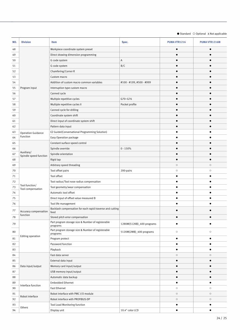
48
Program input
Workpiece coordinate system preset ● ●
49 Direct drawing dimension programming ● ●
50 G code system A ● ●
51 G code system B/C ● ●
52 Chamfering/Corner R ● ●
53 Custom macro ● ●
54 Addition of custom macro common variables #100 - #199, #500 - #999 ● ●
55 Interruption type custom macro ● ●
56 Canned cycle ● ●
57 Multiple repetitive cycles G70~G76 ● ●
58 Multiple repetitive cycles II Pocket profile ● ●
59 Canned cycle for drilling ● ●
60 Coordinate system shift ● ●
61 Direct input of coordinate system shift ● ●
62 Pattern data input ● ●
63 Operation Guidance Function
EZ Guidei(Conversational Programming Solution) ● ●
64 Easy Operation package ● ●
65
Auxiliary/Spindle speed function
Constant surface speed control ● ●
66 Spindle override 0 - 150% ● ●
67 Spindle orientation ● ●
68 Rigid tap ● ●
69 Arbitrary speed threading ○ ○
70
Tool function/Tool compensation
Tool offset pairs 200-pairs ○ ○
71 Tool offset ● ●
72 Tool radius/Tool nose radius compensation ● ●
73 Tool geometry/wear compensation ● ●
74 Automatic tool offset ● ●
75 Direct input of offset value measured B ● ●
76 Tool life management ● ●
77 Accuracy compensation function
Backlash compensation for each rapid traverse and cutting feed
● ●
78 Stored pitch error compensation ● ●
79
Editing operation
Part program storage size & Number of registerable programs
1280M(512KB)_400 programs ● ●
80Part program storage size & Number of registerable programs
5120M(2MB)_400 programs ○ ○
81 Program protect ● ●
82 Password function ● ●
83 Playback ● ●
84
Data input/output
Fast data server ○ ○
85 External data input ● ●
86 Memory card input/output ● ●
87 USB memory input/output ● ●
88 Automatic data backup ● ●
89Interface function
Embedded Ethernet ● ●
90 Fast Ethernet ○ ○
91Robot interface
Robot interface with PMC I/O module ○ ○
92 Robot interface with PROFIBUS-DP ○ ○
93Others
Tool Load Monitoring function ● ●
94 Display unit 10.4" color LCD ● ●
Standard Optional X Not applicable
2726 /
PUMA
VTR1216
series
Product Overview
Basic Information
Basic Structure
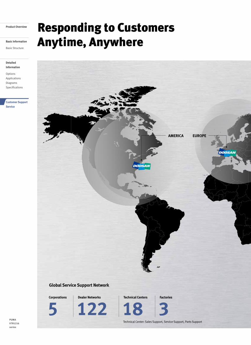
Responding to Customers Anytime, Anywhere
Global Service Support Network
Technical Center: Sales Support, Service Support, Parts Support
5Corporations
3Factories
18Technical Centers
122Dealer Networks
AMERICA EUROPE
Detailed
Information
Options
Applications
Diagrams
Specifications
Customer Support
Service

2726 /
Doosan Machine Tools’ Global Network, Responding to Customer’s Needs nearby, Anytime, AnywhereDoosan machine tools provides a system-based professional support service before and after the machine tool sale by responding quickly and efficiently to customers’ demands.By supplying spare parts, product training, field service and technical support, we can provide top class support to our customers around the world.
We help customers to achieve success by providing a variety of professional services from pre-sales consultancy to post-sales support.
Customer Support Service
- On site service- Machine installation and testing- Scheduled preventive maintenance- Machine repair
Field Services
- Supports machining methods and technology
- Responds to technical queries- Provides technical consultancy
Technical Support
- Programming / machine setup and operation
- Electrical and mechanical maintenance- Applications engineering
Training
- Supplying a wide range of original Doosan spare parts
- Parts repair service
Supplying Parts
Domestic Service Support Network
2Integrated Support Centers 7
Sales Branch Offices
6Post-Sales Service Centers 31
Designated Repair Service Centers
CHINA (Yantai)
CHINA (Shanghai)
INDIA
Changwon Factory
Head Office
JAPAN

Major Specifications
PUMA VTR1216 series Description Unit PUMA VTR1216 PUMA VTR1216M
Capacity
Max machining dia. mm (inch) 1600 (63.0)
Max machining height mm (inch) 1250 (49.2)
Max table load kg (lb) 8000 (1763.7)
Travel distanceX axis (left / right) mm (inch) -700 / +1000 (-27.6 / +39.4)
Z / W axis mm (inch) 1200 / 800 (47.2 / 31.5)
Rapid traverse rate X / Z axis m/min (ipm) 12 / 10 (472.4 / 393.7)
Main spindle
Max spindle speed r/min 400
Max. spindle motor power kW (Hp) 45 {70}* (60.3 {93.9}*)
Max spindle torque N·m (ft-lb) 20557 {31997}* (15171.1 {23613.8}*)
Tool magazine Max tool position ea 12 {24}* 15 {34}*
CNC system DOOSAN-FANUC i
*{ } Option
Head OfficeYeonkang Bldg., 6th FL., 270, Yeonji-dong,
Jongno-gu, Seoul, Korea
Tel +82-2-3670-5345 / 5362
Fax +82-2-3670-5382
Doosan Machine Tools America19A Chapin Rd., Pine Brook, NJ 07058, U.S.A.
Tel +1-973-618-2500
Fax +1-973-618-2501
Doosan Machine Tools ChinaRoom 101,201,301, Building 39 Xinzhuan Highway
No.258 Songjiang District,China Shanghai(201612)
Tel +86 21-5445-1155
Fax +86 21-6405-1472
Doosan Machine Tools EuropeEmdener Strasse 24, D-41540 Dormagen, Germany
Tel +49-2133-5067-100
Fax +49-2133-5067-111
Doosan Machine Tools Japan#2412, Mita Kokusai Bldg. 1-4-28 Mita,
Minato-ku, Tokyo 108-0073, Japan
Tel +81 3 5730 9013
Fax +81 3 5730 9016
Doosan Machine Tools India106 / 10-11-12, Amruthahalli, Byatarayanapura,
Bellary road, Bangalore-560 092, India
Tel +91-80-4266-0122 / 121 / 100
For more details, please contact Doosan Machine Tools. The specifications and information above-mentioned may be changed without prior notice. Doosan Machine Tools Co., Ltd. is a subsidiary of MBK Partners. The trademark is used under a licensing agreement with Doosan Corporation,
the registered trademark holder.
Doosan Machine Toolshttp://www.doosanmachinetools.com
www.facebook.com/doosanmachinetools www.youtube.com/c/DoosanMachineToolsCorporation