pulse transformer and its applications
DESCRIPTION
An essay about pulse transformer.TRANSCRIPT
HỒ CHÍ MINH UNIVERSITY OF TECHNOLOGY
PULSE TRANSFORMER AND ITS APPLICATIONS Instructor: Assoc Prof. Dr. NGUYỄN Hoàng Việt Student: HUỲNH Lê Duy – 40900382 PFIEV-09Télécom
Huỳnh Lê Duy 12/23/2012
HUYNH Le Duy [PULSE TRANSFORMER AND ITS APPLICATIONS]
I
ABSTRACT
Pulse transformer is the designed for operating at high frequency, therefore the transformer can
physically more compact, as well as transfer more power than same-size normal transformer.
The pulse transformer core has better quality due to the Foucault current at high frequency. This
essay also studies the response of the pulse transformer with an ideal pulse and some of its
application.
HUYNH Le Duy [PULSE TRANSFORMER AND ITS APPLICATIONS]
II
Table of Contents
Table of Contents ............................................................................................................................ II
Table of Figure .............................................................................................................................. III
1. INTRODUCTION .................................................................................................................. 1
2. EFFECT OF FREQUENCY ................................................................................................... 2
2.1. Foucault current................................................................................................................ 2
2.1.1. Power dissipation ...................................................................................................... 2
2.1.2. Skin effect ................................................................................................................. 3
2.2. Transformer size ............................................................................................................... 4
3. CONSTRUCTION .................................................................................................................. 5
3.1. Core .................................................................................................................................. 5
3.1.1. Ferrite cores .............................................................................................................. 5
3.1.2. Permalloy cores ......................................................................................................... 6
3.2. Windings .......................................................................................................................... 6
4. CHARACTERISTICS ............................................................................................................ 8
4.1. Pulse response .................................................................................................................. 8
4.1.1. Equivalent circuit ...................................................................................................... 8
4.1.2. Front-Edge Response .............................................................................................. 10
4.1.3. Response at the Top of the Pulse ............................................................................ 11
4.1.4. Trailing-Edge Response .......................................................................................... 12
4.2. Efficiency ....................................................................................................................... 13
5. APPLICATION .................................................................................................................... 14
5.1. Pulse Transformer in Triggering Circuits ...................................................................... 14
5.2. Some real life pulse transformer .................................................................................... 16
5.2.1. Signal Pulse transformer ......................................................................................... 16

HUYNH Le Duy [PULSE TRANSFORMER AND ITS APPLICATIONS]
III
5.2.2. Power pulse transformer ......................................................................................... 16
6. REFERENCES ..................................................................................................................... 18
6.1. Bibliography ................................................................................................................... 18
6.2. Notes............................................................................................................................... 18
Table of Figure
Figure 1 : Symbol of the pulse transformer .................................................................................... 1
Figure 2: Lamination of conductors parallel to the field lines reduce eddy currents ..................... 3
Figure 3: Distribution of current flow in a cylindrical conductor, shown in cross section. For
alternating current, 63% of the electrical current flows between the surface and the skin depth δ 3
Figure 4: Some kind of ferrites cores .............................................................................................. 5
Figure 5: Permalloy cores ............................................................................................................... 6
Figure 6: Litz wire ......................................................................................................................... 7
Figure 7: Hysteresis loop ................................................................................................................ 8
Figure 8: Flat-topped pulse ............................................................................................................. 9
Figure 9: Transformer coupling ...................................................................................................... 9
Figure 10: Equivalent circuit. ....................................................................................................... 10
Figure 11: Circuit for step-up transformer .................................................................................... 10
Figure 12: Influence of transformer constants on front edge of pulse R1=R2 ............................ 11
Figure 13: Circuit for top of pulse ................................................................................................ 12
Figure 14: Droop at top of pulse transformer output voltage ....................................................... 12
Figure 15: Circuit for Trailing-Edge ............................................................................................. 12
Figure 16: Trailing-Edge response................................................................................................ 13
Figure 17 Complete output circuit ............................................................................................... 14
Figure 18 Pulse transformer connection of 2 SCR ....................................................................... 15
Figure 19: Pulse Transformers (1000 Series) | Murata-PS ........................................................... 16
Figure 20: Corona free pulse transformer ..................................................................................... 16
Figure 21: Pulse charging transformer ......................................................................................... 17

HUYNH Le Duy [PULSE TRANSFORMER AND ITS APPLICATIONS]
1
1. INTRODUCTION
A pulse transformer is a transformer that is optimized for transmitting rectangular electrical
pulses (that is, pulses with fast rise and fall times and relatively constant amplitude) to the load
with its shape and other properties unchanged. It is designed for operating at high frequency
from many kHz to hundreds kHz. It can transfer more power compare to the same-size normal
transformer. Pulse transformers find its applications in communication, power electronics, digital
electronics, and fast pulse generation and so on.
In power electronics, Pulse transformer is useful for triggering thyristor, triacs and so on. Pulse
transformer covers a wide range of pulse and power levels.
Small pulse transformers, is used in pulse generators, can deliver only a few Volts at pulse
widths of a few microseconds. Large pulse transformers used in linear accelerator, radar and so
on can deliver wider range of power from 50 to 100MW at 200 to 300kV with pulse duration of
microseconds.
Figure 1 show the symbol of the pulse transformer. But it is able to use the same symbol with
normal transformer with notification of the frequency the transformer is used.
Figure 1 : Symbol of the pulse transformer

HUYNH Le Duy [PULSE TRANSFORMER AND ITS APPLICATIONS]
2
2. EFFECT OF FREQUENCY
2.1. Foucault current
2.1.1. Power dissipation
The biggest problem of operating at high frequency is the Foucault current. Foucault currents
(also called Eddy currents) are electric currents induced within conductors by a changing
magnetic field in the conductor. It will overheat the core and waste power. Look at the Power
dissipation of Foucault currentsi:
2 2 2 2
6
pB d fP
k D
Where
P is the power lost per unit mass (W/kg),
Bp is the peak magnetic field (T),
d is the thickness of the sheet or diameter of the wire (m),
f is the frequency (Hz),
k is a constant equal to 1 for a thin sheet and 2 for a thin wire,
ρ is the resistivity of the material (Ω m), and
D is the density of the material (kg/m3).
From the equation, we found that a higher frequency, power lost will increase. To minimize the
power losses, stacking layers of thin steel laminations is used to construct the core and high
resistivity material is used.
Transformers operate at normal frequency (50-60Hz) is constructed by silicon steel lamination.
But cores made by this material cannot operate at high frequency because Silicon steel has low
resistivity. Thinner laminations reduce losses but are more laborious and expensive to construct.
Higher Foucault current will overheat the transformer and waste power. Therefore, higher
resistivity material is used.

HUYNH Le Duy [PULSE TRANSFORMER AND ITS APPLICATIONS]
3
Figure 2: Lamination of conductors parallel to the field lines reduce eddy currents
2.1.2. Skin effect
In very fast-changing fields, the magnetic field does not penetrate completely into the interior of
the material. The skin effect causes the effective resistance of the conductor to increase at higher
frequencies where the skin depth is smaller and therefore decrease the Power dissipation of the
Foucault current
Figure 3: Distribution of current flow in a cylindrical conductor, shown in cross section. For
alternating current, 63% of the electrical current flows between the surface and the skin depth δ

HUYNH Le Duy [PULSE TRANSFORMER AND ITS APPLICATIONS]
4
The penetration depth can be calculated from the following equation:
1
f
Where:
δ is the penetration depth (m)
f is the frequency (Hz)
μ is the magnetic permeability of the material (H/m)
σ is the electrical conductivity of the material (S/m).
Skin effect is useful in decreasing the losses at high frequency so high permeability material is
used in pulse transformer core
2.2. Transformer size
Transformer universal EMF equation if the flux in the core is purely sinusoidal:
4.44E f N B A
Where:
E is the sinusoidal root mean square voltage of the winding;
is the frequency
N is the number of turns of wire;
B is the peak magnetic flux density;
A is the cross-sectional area of the core.
For the same voltage E, increasing the frequency allows decreasing the number of turn N and by
this decreases the size of the core too. By operating at higher frequencies, transformers can be
physically more compact because a given core is able to transfer more power without reaching
saturation and fewer turns are needed to achieve the same impedance.
HUYNH Le Duy [PULSE TRANSFORMER AND ITS APPLICATIONS]
5
3. CONSTRUCTION
3.1. Core
Pulse Transformer is similar to normal transformer: it has primary winding(s) and secondary
winding(s) which is wound around a core. But due to its operating point a high frequency, the
cores are made of ferrites or of special high permeability silicon steel such as Hipersil or
Permalloy ii
3.1.1. Ferrite cores
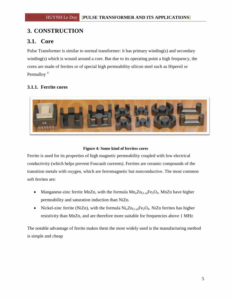
Figure 4: Some kind of ferrites cores
Ferrite is used for its properties of high magnetic permeability coupled with low electrical
conductivity (which helps prevent Foucault currents). Ferrites are ceramic compounds of the
transition metals with oxygen, which are ferromagnetic but nonconductive. The most common
soft ferrites are:
Manganese-zinc ferrite MnZn, with the formula MnaZn(1-a)Fe2O4. MnZn have higher
permeability and saturation induction than NiZn.
Nickel-zinc ferrite (NiZn), with the formula NiaZn(1-a)Fe2O4. NiZn ferrites has higher
resistivity than MnZn, and are therefore more suitable for frequencies above 1 MHz
The notable advantage of ferrite makes them the most widely used is the manufacturing method
is simple and cheap

HUYNH Le Duy [PULSE TRANSFORMER AND ITS APPLICATIONS]
6
3.1.2. Permalloy cores
Figure 5: Permalloy coresiii
Permalloy is a nickel-iron magnetic alloy, with about 20% iron and 80% nickel. The alloy is
called by the proportion of Nikel, for example Permalloy75 is permalloy with 75% atom is niken
(or Ni75Fe25).
It is notable for its very high magnetic permeability, which makes it useful as a magnetic core
material in electrical and electronic equipment. The name permalloy is made with “perm” in
permeability and “alloy”. In addition to high permeability, its other magnetic properties are low
coercivity, near zero magnetostriction, and significant anisotropic magnetoresistance. The low
magnetostriction is critical for industrial applications, allowing it to be used in thin films where
variable stresses would otherwise cause a ruinously large variation in magnetic properties
3.2. Windings
By operating at high frequency, fewer turns are needed to achieve the needed impedance. For
small power and signal transformers, in which currents are low and the potential difference
between adjacent turns is small, the coils are often wound from enamelled magnet wire, such as
Formvar wire. Larger power transformers operating at high voltages may be wound with copper
rectangular strip conductors insulated by oil-impregnated paper and blocks of pressboard. High-

HUYNH Le Duy [PULSE TRANSFORMER AND ITS APPLICATIONS]
7
frequency transformers operating in the tens to hundreds of kilohertz often have windings made
of braided Litz wire to minimize the skin-effect and proximity effect losses
Figure 6: Litz wire iv

HUYNH Le Duy [PULSE TRANSFORMER AND ITS APPLICATIONS]
8
4. CHARACTERISTICS
Pulse Transformers are different from ordinary transformers in that they have a square hysteresis
loop. This indicates that the magnetization can be only in two statesv. Than change from on state
to another takes place almost instantaneously in pulse transformer, whereas the change is only
gradual in ordinary transformers.
Figure 7: Hysteresis loop
Pulse transformer work with square waveforms and pulse waveforms. When a pulse is applied to
its primary, a pulse transformer produces a sharp pulse across its secondary, instantaneously. It
also provides isolation between 2 primary and secondary, therefore can be used in applications
which require isolation between the main circuit and that which supply the pulses.
Pulse transformer needs to have low values of leakage inductance and distributed capacitance,
and a high open-circuit inductance to minimize distortion of the pulse shape. In power-type pulse
transformers, a low coupling capacitance (between the primary and secondary) is important to
protect the circuitry on the primary side from high-powered transients created by the load
4.1. Pulse responsevi
4.1.1. Equivalent circuit
We analyse the response for a square- or flat-topped pulse impressed upon the transformer:

HUYNH Le Duy [PULSE TRANSFORMER AND ITS APPLICATIONS]
9
Figure 8: Flat-topped pulse
With the input is a pulse shown in Fig. 6, and a generalized circuit for the amplifier is shown in
Fig. 7. The equivalent circuit for this amplifier is given in Fig. 8. At least this is applied to the
front edge of the pulse.
Figure 9: Transformer coupling
Front edge of the pulse is rising suddenly from zero to an steady value E. This change is sudden,
so the transformer Open Circuit Inductance (OCL) is considered as infinite impedance and is
omitted in Fig. 10
HUYNH Le Duy [PULSE TRANSFORMER AND ITS APPLICATIONS]
10
Figure 10: Equivalent circuit.
Where R1,R2 represents the source and the load resistance, Winding capacitances are shown as
C1 and C2 for the primary and secondary windings, respectively, LS is leakage inductance of the
transformer, the pulse source is made by an ideal switch
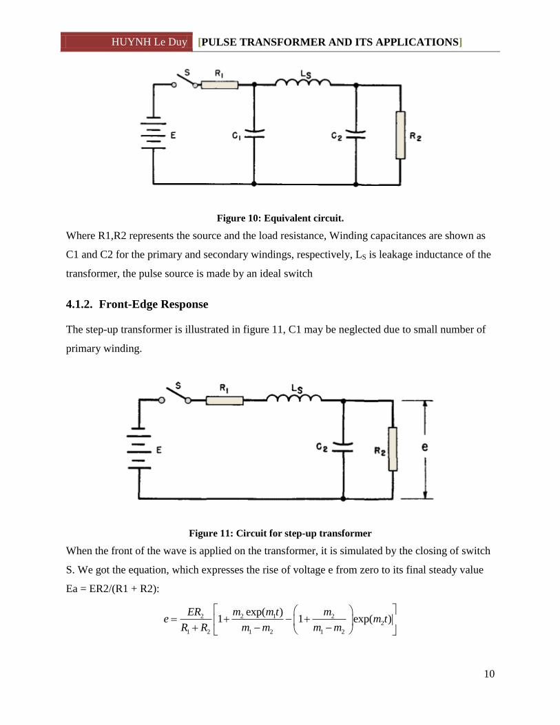
4.1.2. Front-Edge Response
The step-up transformer is illustrated in figure 11, C1 may be neglected due to small number of
primary winding.
Figure 11: Circuit for step-up transformer
When the front of the wave is applied on the transformer, it is simulated by the closing of switch
S. We got the equation, which expresses the rise of voltage e from zero to its final steady value
Ea = ER2/(R1 + R2):
2 2 1 22
1 2 1 2 1 2
exp( )1 1 exp( )
ER m m t me m t
R R m m m m
HUYNH Le Duy [PULSE TRANSFORMER AND ITS APPLICATIONS]
11
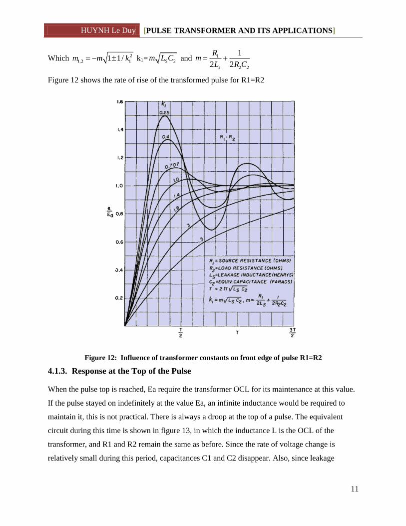
Which 2
1,2 11 1/m m k k1= 2Sm L C and 1
2 2
1
2 2s
Rm
L R C
Figure 12 shows the rate of rise of the transformed pulse for R1=R2
Figure 12: Influence of transformer constants on front edge of pulse R1=R2
4.1.3. Response at the Top of the Pulse
When the pulse top is reached, Ea require the transformer OCL for its maintenance at this value.
If the pulse stayed on indefinitely at the value Ea, an infinite inductance would be required to
maintain it, this is not practical. There is always a droop at the top of a pulse. The equivalent
circuit during this time is shown in figure 13, in which the inductance L is the OCL of the
transformer, and R1 and R2 remain the same as before. Since the rate of voltage change is
relatively small during this period, capacitances C1 and C2 disappear. Also, since leakage

HUYNH Le Duy [PULSE TRANSFORMER AND ITS APPLICATIONS]
12
inductance usually is small compared with the OCL, it is neglected. The responded is provided in
figure 14. Several curves are given for several types of pulse depended on R1 and R2
Figure 13: Circuit for top of pulse
Figure 14: Droop at top of pulse transformer output voltage
4.1.4. Trailing-Edge Response
At instant b in figure 8, it is simulated that the switch S in figure 10 is opened suddenly. The
equivalent circuit now reverts to that shown in figure 15
Figure 15: Circuit for Trailing-Edge

HUYNH Le Duy [PULSE TRANSFORMER AND ITS APPLICATIONS]
13
which Le is the OCL, RI,CD total resistance and capacitance referred to the primary. Figure 15
show the trailing edge response. The equation for which is:
1 1 2 2
1 2
2 exp 2 expaEe m m m t m m m t
m m
Which
2
1,2 3 3
/1 Magnetizing current1 1 1/ , , , 2 ,
2 2 Load current
e D
I D e D
I
L Cm m k m R C k T L C
R
Figure 16: Trailing-Edge response
4.2. Efficiency
Pulse transformers have high efficiency. By using high resistivity and permeability it reduce the
power losses by Foucault current. Copper losses are also reducing because less winding is
require than those normal transformer.
Efficiencies of over 90 per cent are common in pulse transformers, and with high-permeability
materials over 95 per cent may be obtained. vii
HUYNH Le Duy [PULSE TRANSFORMER AND ITS APPLICATIONS]
14
5. APPLICATION
Some applicationviii
:
Power transformer supply 50Hz AC power
Converter: Fly-back, Push-Pull
AF transformer are used in audio stage of amply, radio, TV
Supply pulse to trigger SCRs, magnetism, etc.
Change the amplitude of a pulse
Invert the polarity of a pulse
Differentiate a pulse.
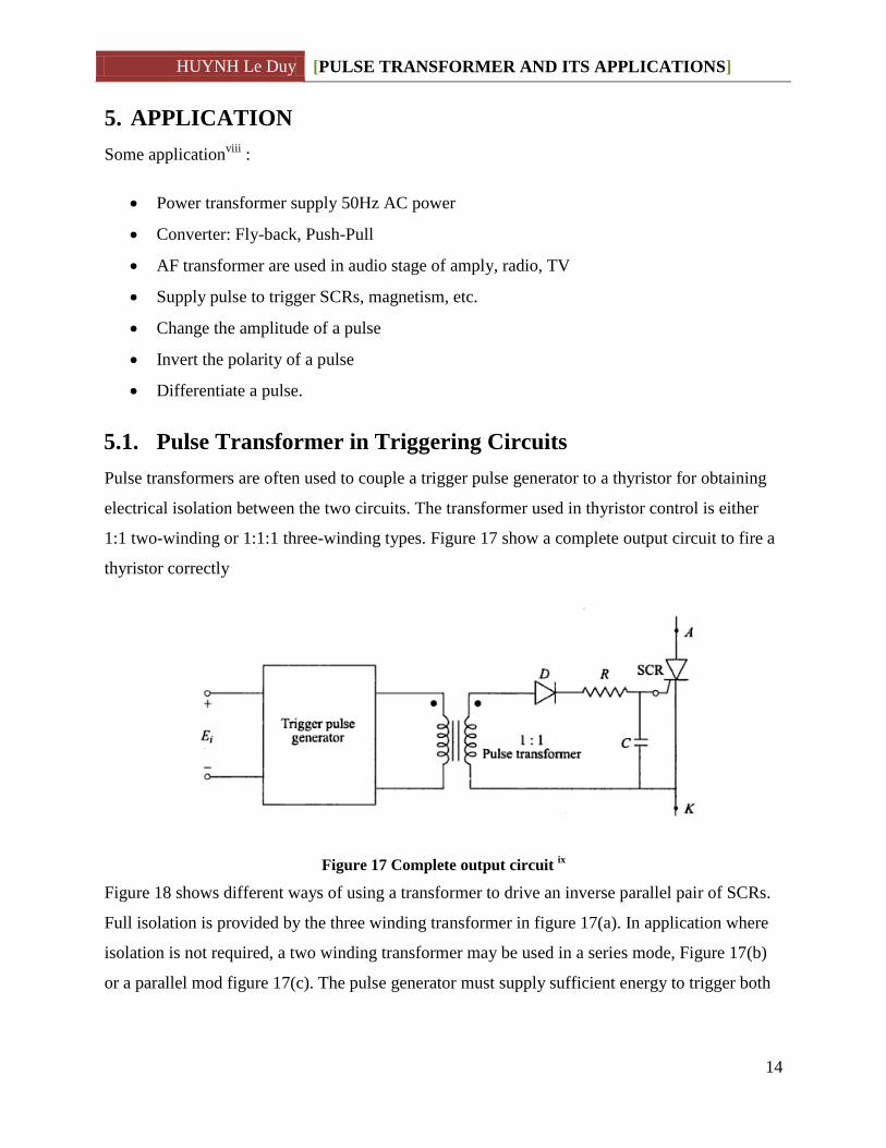
5.1. Pulse Transformer in Triggering Circuits
Pulse transformers are often used to couple a trigger pulse generator to a thyristor for obtaining
electrical isolation between the two circuits. The transformer used in thyristor control is either
1:1 two-winding or 1:1:1 three-winding types. Figure 17 show a complete output circuit to fire a
thyristor correctly
Figure 17 Complete output circuit ix
Figure 18 shows different ways of using a transformer to drive an inverse parallel pair of SCRs.
Full isolation is provided by the three winding transformer in figure 17(a). In application where
isolation is not required, a two winding transformer may be used in a series mode, Figure 17(b)
or a parallel mod figure 17(c). The pulse generator must supply sufficient energy to trigger both

HUYNH Le Duy [PULSE TRANSFORMER AND ITS APPLICATIONS]
15
SCRs, and the pulse transformer (plus any additional resistors) must supply sufficient gate
current to both SCRs under worst condition of unbalanced gate impedances
Figure 18 Pulse transformer connection of 2 SCRx
If the SCRs is trigger at 50Hz, The signal is go through an And gate with a high frequency pulse
to prevent the magnetic saturation of the core.
A trigger transformer is primarily use to enhance the efficiency.xi
HUYNH Le Duy [PULSE TRANSFORMER AND ITS APPLICATIONS]
16
5.2. Some real life pulse transformer
5.2.1. Signal Pulse transformer
Figure 19: Pulse Transformers (1000 Series) | Murata-PS xii
The 1000 series are intended for wideband and pulse operations. They are also suitable for signal
isolation and use in small isolated power supplies. The compact footprint makes them ideal for
applications where space is at a premium.
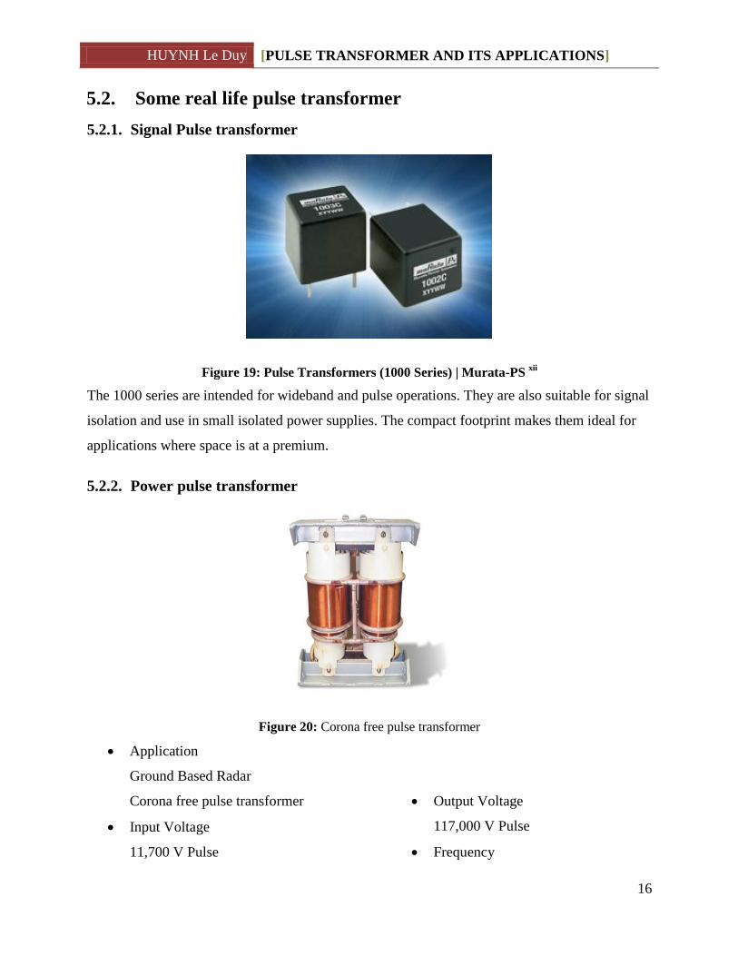
5.2.2. Power pulse transformer
Figure 20: Corona free pulse transformer
Application
Ground Based Radar
Corona free pulse transformer
Input Voltage
11,700 V Pulse
Output Voltage
117,000 V Pulse
Frequency

HUYNH Le Duy [PULSE TRANSFORMER AND ITS APPLICATIONS]
17
250 pps
Duty Cycle
0.192%
Figure 21: Pulse charging transformer xiii
This transformer is used in the doubling project (sled) at Stanford linear accelerator center (slac).
The unit is rated at 270 kilovolts, 75 megawatts, for a 7 microsecond pulse. By using precision
winding and construction techniques it was possible to limit the rise time to 0. 5 microseconds
(10-90), while maintaining less than 0. 15% p-p flat top ripple. The tapered (constant gradient)
secondary windings limit the leakage inductance to almost half of what it would be with the
conventional construction.

HUYNH Le Duy [PULSE TRANSFORMER AND ITS APPLICATIONS]
18
6. REFERENCES
6.1. Bibliography
[1] M D Singh, K B Khanchandani, Power Electronics 2e, Tata McGraw-Hill Education.
[2] Reuben Lee, Electronic Transformers and Circuits second edition, john willey & sons, inc,
1955.
[3] B. Somanathan Nair, Electronic Devices And Applications, PHI Learning Pvt. Ltd..
[4] Prasad Rajendra, Fundamentals Of Electrical Engineering 2Nd Ed., PHI.
6.2. Notes
i http://en.wikipedia.org/wiki/Eddy_current
ii Fundamentals Of Electrical Engineering 2Nd Ed. [4]
iii http://www.alibaba.com/product-gs/241500451/permalloy_core_Magnetic_core_Tape_wound.html
iv http://en.wikipedia.org/wiki/Litz_wire
v Electronic Devices And Applications p27 [3]
vi Electronic Transformers and Circuits second edition p297 [2]
vii Electronic Transformers and Circuits second edition p314 [2]
viii Electronic Devices And Applications p27 [3]
ix Power Electronics 2e p76 [1]
x Power Electronics 2e p77-78 [1]
xi Power Electronics 2e p78 [1]
xii http://www.ttiinc.com/object/Murata-Power-Pulse-Transformer-1000-Series.html
xiii http://www.stangenes.com/pulse-transformers.html