pulse techniques and logical circuitry*w140.com/rosenheim_anderson_vhf_pulse.pdfforward impedanceof...
TRANSCRIPT

PROCEEDINGS OF THE IRE
VHF Pulse Techniques and Logical Circuitry*D. E. ROSENHEIMt, SENIOR MEMBER, IRE, AND A. G. ANDERSONt, ASSOCIATE MEMBER, IRE
Summary-Techniques and components for use in systemshandling pulses of lO-millimicrosecond width have been investigated.Bandwidth requirements have led to the use of secondary emissionpentodes in amplifier service. The limitations of time delay in feed-back type circuitry have made necessary the use of special logicalreshaping circuits. A test program on commercially available semi-conductor diodes resulted in the selection of high-conductance, gold-bonded junction diodes for use in switching circuits. Multivibratorcircuits have been designed for gating and delay functions. Electro-magnetic delay lines of both the coaxial and helical-wound types havebeen used for delay and for pulse generation.
These components have been applied to the design of an arith-metic unit which performs binary addition, multiplication, and dy-namic storage at a pulse repetition rate of 50 megacycles per second.
INTRODUCTION
pULSE-CODED information systems have foundapplication in communications, digital computers,and nuclear inistrumentation. The desire to handle
a maximum amount of information in a minimumamount of time has led to the development of systemsusing increasingly narrow pulses at increasingly highrepetition rates. Resolution of millimicrosecond pulsesat low repetition rates has been demonstrated in nuclearinstrumentation research."2 A 50-megacycle per secondpulse repetition rate using pulses 10 millimicrosecondswide was considered by the auithors to be a practicalupper limit oln the basis of the available componentsand the state of measuiring techlniquies. Havilng estab-lished this repetition rate, componients anid circuits weredeveloped to perform amplification, pulse shaping, andswitching. An interesting application is the demonstra-tion that digital computer operations can be performedat a 50-megacycle pulse repetitioni rate using these com-ponents and circuits.
PULSE AMPLIFIERS
The rise time3 in seconds of anl tTncompensatedpentode video amplifier is given by
tr = 2.2RC,where R is the plate load resistance in ohms, and C is thetotal capacity in farads at the plate. For a 10-milli-microsecond pulse, assuming an allowable rise time of4.4 millimicroseconds, and a value of C of 10 micro-microfarads, R is found to be 200 ohms. When using an
* Original manuscript received by the IRE, September 4, 1956.t IBM Watson Lab., Columbia University, New York, N. Y.I I. A. Lewis and F. H. Wells, "Millimicrosecond Pulse Tech-
niques," McGraw-Hill Book Company, Inc., New York, N. Y.; 1954.2 N. F. Moody, G. J. R. Maclusky and M. 0. Deighton, "Milli-
microsecond pulse techniques," Electronic Eng., vol. 24, pp. 214-219;May, 1952.
3 Committee Personnel, "IRE standards on pulses: methods ofmeasurement of pulse quantities, 1955," PROC. IRE, vol. 43, pp.1610-1616; November, 1955.
amplifier to re-establish pulse amplitude anid to decreasepulse rise and fall times, the amplifier gaini shouild be ofthe order of 3 to 5. Postulatinig a miniimum gainI, Ao, of3 from such a stage the average g,n requiireimenit is givenb)y:
gm = Ao/R = 3/200 = 15,000 ,imhos.
Using vacuum tubes either clamped on or biased off,signal levels of from 5 to 10 volts are required. Assuminigan 8-volt signal level and 200-ohm load resistance therequired peak tube current is 40 ma.Although much progress is being made in the field of
high-speed semiconductor devices, there are no avail-able transistors at the time of this writing which willoperate at a 50-megacycle per second pulse repetitionrate. An examination of available vacuum tubes led tothe choice of the Western Electric 417A/5842 triode andthe Philips EFP-60 secondary emission pentode. TheWestern Electric 417A/5842 triode has a gm of 25,000yimhos, a plate dissipation of 4 watts, a maximum aver-age plate current of 35 ma, a cathode to grid and heatercapacity of 9 micromicrofarads, and a plate to grid andheater capacity of 1.8 micromicrofarads. The PhilipsEFP-60 secondary emissioni pentode has a grid to anodetran-sconductanice of 25,000 Aumhos, a pltte dissipation-of 2 watts, a dyniode dissipatioln of 1 watt, a miiaximumaverage cathode curreint of 8 ma, and a total inpuit pIlIsoutput capacity of about 15 micromlicrofarads. TheEFP-60 has the advantage of havinig ain additioinal ac-tive electrode, the dynode, which allows the tube to beused as a noninvertilng amplifier with a grid to dynodetransconductance of 20,000 Aemhos. One may make useof the active electrodes of the EFP-60 to obtain circuitswhich would require 2 tubes of coinventional design.A noninverting limiter amplifier is showin in Fig. 1.
Power supply decoupling and parasitic suppressionresistors have been employed, and shunit peakiing hasbeen used to decrease the rise time of the signal on thedynode to about 3 millimicroseconds. This amplifier isnormally biased below cutoff and is driven positive bypulses fed to its control grid through a dc restorer cir-ctuit, which mainitains the grid at a constanit dc biasvoltage. The use of positive pulses, feeding the cutoffgrid, has the advantages of eliminiation of baselinenoise and the reduction of average power dissipationi.The diode-resistor combiniationi in the cathode circuit ofthe amplifier allows the ttibe to draw 10-ma cathodecurrent withouit degeneration. Hovever, if the tubedraws more than 10-ma current, the diode opens and thegain is reduced by a factor of twenity-five. The 10-macathode current produces approximately 40 ma of dy-node current so that the peak output voltage from the
212 F+ebritary
Rosenheim and Anderson: VI1fF Pulse Techniques and Logicai Circuitry
+ 275 +150
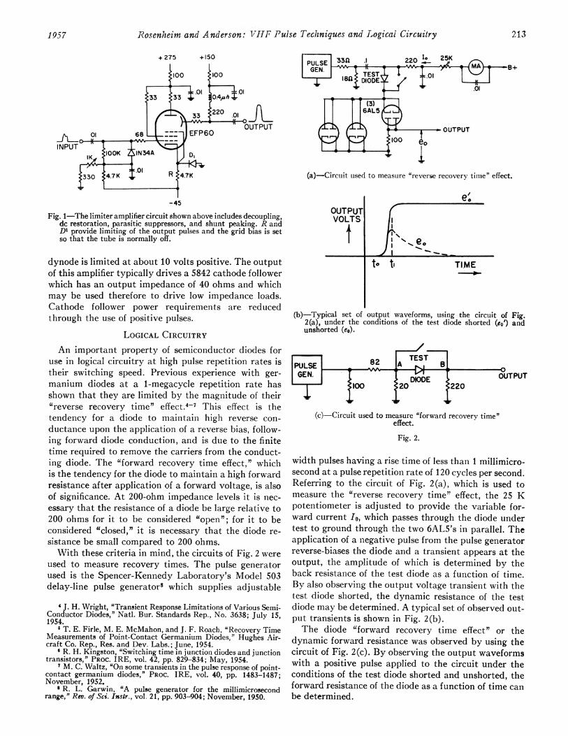
(a)-Circuit used to measure "reverse recovery time" effect.
-45
Fig. 1-The limiter amplifier circuit shown above includes decoupling,dc restoration, parasitic suppressors, and shunt peaking. R andDI provide limiting of the output pulses and the grid bias is setso that the tube is normally off.
dynode is limited at about 10 volts positive. The outputof this amplifier typically drives a 5842 cathode followerwhich has an output impedance of 40 ohms and whichmay be used therefore to drive low impedance loads.Cathode follower power requirements are reducedthrough the use of positive pulses.
LOGICAL CIRCUITRYAn important property of semiconductor diodes for
use in logical circuitry at high pulse repetition rates istheir switching speed. Previous experience with ger-manium diodes at a 1-megacycle repetition rate hasshown that they are limited by the magnitude of their"reverse recovery time" effect.4-7 This effect is thetendency for a diode to maintain high reverse con-ductance upon the application of a reverse bias, follow-ing forward diode conduction, and is due to the finitetime required to remove the carriers from the conduct-ing diode. The "forward recovery time effect," whichis the tendency for the diode to maintain a high forwardresistance after application of a forward voltage, is alsoof significance. At 200-ohm impedance levels it is nec-essary that the resistance of a diode be large relative to200 ohms for it to be considered "open"; for it to beconsidered "closed," it is necessary that the diode re-sistance be small compared to 200 ohms.With these criteria in mind, the circuits of Fig. 2 were
used to measure recovery times. The pulse generatorused is the Spencer-Kennedy Laboratory's Model 503delay-line pulse generator8 which supplies adjustable
I J. H. Wright, "Transient Response Limitations of Various Semi-Conductor Diodes," Natl. Bur. Standards Rep., No. 3638; July 15,1954.
6 T. E. Firle, M. E. McMahon, and J. F. Roach, "Recovery TimeMeasurements of Point-Contact Germanium Diodes," Hughes Air-craft Co. Rep., Res. and Dev. Labs.; June, 1954.
6 R. H. Kingston, "Switching time in junction diodes and junctiontransistors," PROC. IRE, vol. 42, pp. 829-834; May, 1954.
' M. C. Waltz, "On some transients in the pulse response of point-contact germanium diodes," PROC. IRE, vol. 40, pp. 1483-1487;November, 1952.
8 R. L. Garwin, "A pulse generator for the millimicrosecondrange," Rev. of Sci. Insir., vol. 21, pp. 903-904; November, 1950.
OUTPUTVOLTS
a-
to ti TIME0
(b)-Typical set of output waveforms, using the circuit of Fig.2(a), under the conditions of the test diode shorted (co') andunshorted (eo).
(c) Circuit used to measure "forward recovery time"effect.
Fig. 2.
width pulses having a rise time of less than 1 millimicro-second at a pulse repetition rate of 120 cycles per second.Referring to the circuit of Fig. 2(a), which is used tomeasure the "reverse recovery time" effect, the 25 Kpotentiometer is adjusted to provide the variable for-ward current Io, which passes through the diode undertest to ground through the two 6AL5's in parallel. Theapplication of a negative pulse from the pulse generatorreverse-biases the diode and a transient appears at theoutput, the amplitude of which is determined by theback resistance of the test diode as a function of time.By also observing the output voltage transient with thetest diode shorted, the dynamic resistance of the testdiode may be determined. A typical set of observed out-put transients is shown in Fig. 2(b).The diode "forward recovery time effect" or the
dynamic forward resistance was observed by using thecircuit of Fig. 2(c). By observing the output waveformswith a positive pulse applied to the circuit under theconditions of the test diode shorted and unshorted, theforward resistance of the diode as a function of time canbe determined.
1957 213
eo-
II "I %
,,. e.II '11- - --

PROCEEDINGS OF THE IRE
Many commercial point-contact germanium diodeswere found to have satisfactory reverse recovery timeswhen working into a 200-ohm load. The need for a diodewith a dynamic forward resistance which is small com-pared to 200 ohms led to an investigation of junctiontypes, gold-bonded types, and various "high conduc-tance" types of recent origin. In general, it was foundthat large junction area types were satisfactory in re-gard to forward resistance, but that their "reverserecovery" characteristics were inferior to the averagepoint-contact diode. The gold-bonded junction typeswere found to have high forward conductance and, insome cases, satisfactory "reverse recovery" charac-teristics. Several diode types [e.g. lN308 (CK741),9T6G, T-IN283] have been found which give satisfactoryrecovery characteristics with minimum variation ofparameters during service.The requirements for a logical AND circuit using
these diodes can best be understood by referring to astandard 2-input AND circuit, as shown in Fig. 3(a).The initial rate of rise when driving a capacitive load isgiven by
de/dt = i/c.
For a rate of rise of 2 volts per millimicrosecond with acapacitive load of 10 micromicrofarads (e.g., tube inputcapacity) a current of 20 ma is necessary. With currentsas high as these and 5-10-volt signal levels, the imped-ances of the sources driving the AND circuit inputsmust be kept low in order to eliminate unwanted re-sponses at the output of the AND circuit when fewerthan all of the inputs to an AND circuit rise. Drivingsource impedances can be reduced by using 5842 cathodefollowers to drive the AND circuit inputs or by the useof the AND circuit design shown in Fig. 3(b). In thiscircuit the catcher diodes and resistors compensate forthe source impedance, and the rise of the output whenone leg rises is only a fraction of a volt.
In the case of the OR circuit which is shown in Fig.3(c), the output rises when either or both inputs rise.The output rise time is a function of the output im-pedance of the pulse source at the OR circuit input, theforward impedance of the diode, the OR circuit resistorR, and the load impedance. The fall time is determinedby the OR circuit resistor R, and the load impedance.Rise and fall times of approximately 5 millimicro-seconds are typical for the AND and OR circuits.
PULSE GENERATORS, MULTIVIBRATORS,AND GATES
Test work at vhf pulse repetition rates requires pulsegenerators, multivibrators, and gating circuits as stand-ard test equipment. As outlined above, few componentsare available with which to construct these circuits.Because of its possibilities for noninverted power-gainwith either grid or cathode input terminals (dynode or
INPUT i
INPUT 2
:R
OUTPUT_1_-
(a)-Standard 2-input AND circuit usingsemiconductor diodes.
INPUT 2
(b)-Modified 2-input AND circuit which effectivelyreduces the driving source impedances.
INPUT2I o
0-~~~~~~
(c)-Standard 2-input OR circuit.
Fig. 3.
plate output terminals), the EFP-60 has been thepreferred tube for use in high-speed regenerative cir-cuits. These circuits are of general interest and are out-lined below.The cathode to plate current gain of a secondary
emission pentode is utilized in the plate-cathodecoupled multivibrator10 of Fig. 4.
In the astable configuration shown the repetition rateis determined by C, Ro, R1, and the B voltage, while thepulse width is determined by C, R0, and the tube char-acteristics. The grid may be used as a high impedancesync or trigger terminal, while the dynode may be usedas an isolated output terminal supplying positive pulses.The condition for regeneration, neglectiiig stray ca-pacitance, may be derived from the high-frequencyequivalent circuit shown in Fig. 4(b) with the require-ment that current-gain from cathode-to-plate-to-cathodebe greater than one.
10 F. H. Wells, "Fast pulse circuit techniques for scintillationcounters," Nucleonics, vol. 10, pp. 28-33; April, 1952.9 No longer in production.
- - U
214 February
Rosenheim and Anderson: VHF Pulse Techniques and Logical Circuitry
+275 +150
:220
c
.01_41---0OUTPUT
,22K 11'IOK JRNIOKJ
-150
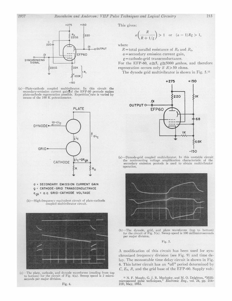
(a)-Plate-cathode coupled multivibrator. In this circuit thesecondary-emission current gainTof the EFP-60 pentode makesplate-cathode regeneration possible. Repetition'rate is varied bymeans of the 100 K potentiometer.
This gives:
/ R \atG _x ) > I or (a- l)Rg > 1,
whereR=total parallel resistance of Ro and Ri,a=secondary emission current gain,g = cathode-grid transconductance.
For the EFP-60, a_5, g_5000 ,umhos, and thereforeregeneration occurs only if R>50 ohms.The dynode grid multivibrator is shown in Fig. 5."
+275
.01
PLATE
+150
t atc
:68
(a)-Dynode-grid coupled multivibrator. In this unstable circuitthe noninverting voltage amplification characteristic of thesecondary emission pentode is used to obtain multivibratoroperation.
a = SECONDARY EMISSION CURRENT GAINg = CATHODE-GRID TRANSCONDUCTANCE
egkz a.C. GRID-CATHODE VOLTAGE
(b)-High-frequency equivalent circuit of plate-cathodecoupled multivibrator circuit.
(c)-The plate, cathode, and dynode waveforms (reading from topto bottom) for the circuit of Fig. 4(a). Sweep speed is 2 micro-seconds per major division.
Fig. 4.
(b)-The dynode, grid, and plate waveforms (top to bottom)for the circuit of Fig. 5(a). Sweep speed is 100 millimicrosecondsper major division.
Fig. 5.
A modification of this circuit has been used for syn-chronized frequency division (see Fig. 9) and time de-lay. The monostable time delay circuit is shown in Fig.6. This latter circuit has an "off" period determined byC, Eo, R, and the grid base of the EFP-60. Supply volt-
" N. F. Moody, G. J. R. Maclusky, and M. 0. Deighton, "Milli-microsecond pulse techniques,' Electronic Eng., vol. 24, pp. 214-219; May, 1952.
2151957

PROCEEDINGS OF THE IRE
as short as 4 millimicroseconds, and amplitudes of theorder of 10 volts across 200 ohms have been obtainedwith this circuit. By injecting a synchronizing signalthis circuit may also be used for synchronized frequencydivision. (See Fig. 9.)
OUTPUT
-150 -ISO -150
(a)-Dynode-grid monostable multivibrator. The stable operat-ing condition is with the EFP-60 'on" and with the EFP-60grid at ground potential. Upon application of a negative triggerpulse the tube cuts off regeneratively and the grid falls to EG.EFP-60 remains cutoff until the voltage across C has fallen to avalue sufficiently low to allow conduction. At this time the stableoperating point is regeneratively re-established.
(b)-The cathode, trigger, and plate waveforms (top to bottom)for the circuit of Fig. 6(a). The cathode and trigger wave-
forms were obtained by using the Tektronix 531 amplifiers, whichhave a rise time of 35 millimicroseconds, while the plate waveformwas obtained by direct connection to the deflection plates through200-ohm cable. The sweep speed is 100 millimicroseconds per
major division.
Fig. 6.
age variations have only a second order effect on thisperiod, since the EFP-60 is used only to charge C be-tween limits set by Eo and ground, and since supplyvoltage changes which produce a change in current
through R, produce a compensating change in Eo.Pulse rise times in the EFP-60 multivibrator circuits
are as short as 10 to 15 millimicroseconds and pulsewidths may be as short as 25 millimicroseconds. The4-millimicrosecond transit time of the EFP-60 accountsfor part of the rise time when used in regenerative cir-cuitry. Output amplitudes are from 10 to 14 voltsacross 200 ohms.
Fig. 7 shows a "regenerative pulse generator"'2 whichhas been used as a source of short pulses. The op-
eration of the circuit is such that pulses are producedhaving a width determined by circuit bandwidth, and a
repetition rate determined by the total delay time.Repetition rates as high as 80 megacycles, pulse widths
" C. C. Cutler, "The regenerative pulse generator," PROC. IRE.vol. 43, pp. 140-148; February, 1955.
-150
Fig. 7-Regenerative pulse generator. Pulses were produced having awidth determined by circuit bandwidth and a repetition rate de-termined by the total delay time through the tube and theRG-62/U coaxial cable.
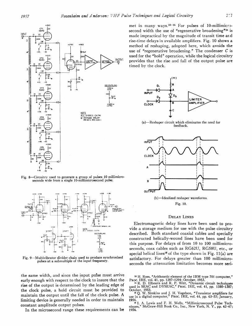
A method for generating a group of coded pulses10 millimicroseconds wide with a 20-millimicrosecondpulse spacing from a single 10-millimicrosecond pulseis shown in Fig. 8. Cathode followers 1 to 5 are suc-
cessively driven negative by the pulse which travelsdown the tapped line. External switches set up the cur-
rent through tubes 1 to 5. The output pulses are mixedin the diode OR circuit and amplified in the followingstages.When working at a 50-megacycle pulse repetition rate
synchronized lower frequency pulses are needed fortriggering oscilloscopes as well as synchronizing auxili-ary circuitry. These pulses are provided by the circuit ofFig. 9, making use of the methods described above.
RESHAPING
As a pulse proceeds through successive stages ofcircuitry, both its timing and wave-shape deteriorate.In order to compensate for these effects retiming and re-
shaping circuitry must be provided. The function of thereshaper is to produce a retimed fixed amplitude outputpulse if, and only if, an input pulse is present at a speci-fied "clock" time. The reshaper normally includes input,output and clock terminals, as well as logical circuitryand an amplifying device.
Clock and input timing is set so that the input pulseis at full amplitude at the time of the appearance of theclock pulse. During the coincidence time of the clockand input pulses, circuits are set up which insure theproduction of a standard output pulse. Since the input,output, and clock pulses are normally of approximately
RG-62/U
216 February
Rosenheim and / nderson: T7ifF Puise Tecihniques anad Logicai Circuitry
CFI5842
INPUT
+2750 +150D
DECOUPLING+150 or+275
1004.01#Sd
+150D or+275D
NOTEALL DIODES-CK741D-20musec. DELAY
(RC 62/U 930 COAX)
Fig. 8-Circuitry used to generate a group of pulses 10 millimicro-seconds wide from a single 10-millimicrosecond pulse.
.,50D .275D +ISOD -2750 .,50D .2750 .2753 +IS6C,
5~~~~~~~~~~ SC +<5}
0 ,.f 6 25 20
- U +soS 2 . 2 2 - ...2 WIDT HINPUT 15 EFP60EfP60iFP60 EP6O FP60O EFP6O
47 47 7 28 2 O7. 22!
-t50D -ISOD -1500
>8 SODISOD ~~~~~~200nPULSE-FORMING L1NENOTE
I12AT7 212AT7 ALL DIODES-CK741
DECOUPLINGd 15 + so
07U347 72
SO10D 50 1506 +275D
Fig. 9-Multivibrator divider chain used to produce synchronizedpulses at a submultiple of the input frequency.
the same width, and since the input pulse must arriveearly enough with respect to the clock to insure that therise of the output is determined by the leading edge ofthe clock pulse, a hold circuit must be provided tomaintain the output until the fall of the clock pulse. Alimiting device is generally needed in order to maintainconstant amplitude output pulses.
In the microsecond range these requirements can be
met in many ways. 13-11 For pulses of 10-millimicrc-second width the use of "regenerative broadening"1' ismade impractical by the magnitude of transit time arAdrise-time delays in available amplifiers. Fig. 10 shows amethod of reshaping, adopted here, which avoids theuse of "regenerative broadening." The condenser C isused for the "hold" operation, while the logical circuitryprovides that the rise and fall of the output pulse airetimed by the clock.
DI
CLOCK ' B AMPLIFE
(a)-Reshaper circuit which eliminates the need forfeedback.
INPUT
CLOCK 11l
AAAI I,
BA |
B
OUTPUT
(b)-Idealized reshaper waveforms.
Fig. 10.
DELAY LINES
Electromagnetic delay lines have been used to pro-vide a storage medium for use with the pulse circuitrydescribed. Both standard coaxial cables and speciallyconstructed helically-wound lines have been used forthis purpose. For delays of from 10 to 100 millimicro-seconds, coax cables such as RG62U, RG58U, etc., orspecial helical lines16 of the type shown in Fig. 11(a) aresatisfactory. For delays greater than 100 millimicro-seconds the attenuation limitation becomes more seri-
13 H. Ross, "Arithmetic element of the IBM type 701 computer,"PROC. IRE, vol. 41, pp. 1287-1294; October, 1953.
14 R. D. Elbourn and R. P. Witt, "Dynamic circuit techniquesused in SEAC and DYSEAC," PROC. IRE, vol. 41, pp. 1380-1387;October, 1953.
15 Q. W. Simkins and J. H. Vogelson, "Transistor amplifiers foruse in a digital computer," PROC. IRE, vol. 44, pp. 43-55; January,1956.
16 I. A. Lewis and F. H. Wells, "Millimicrosecond Pulse Tech-niques," McGraw-Hill Book Co., Inc., New York, N. Y., pp. 42-47;1954.
A , A.
/;1957

PROCEEDINGS OF THE IRE
ous. Since skin effect attenuation in the frequency rangeof interest is inversely proportional to wire size, andsince characteristic impedance is determined by geom-etry, the problem is solved for a given impedance by theuse of larger diameter coax (e.g., RG-15U), or largerdiameter spiral lines. An example of the latter is shownin Fig. 11(b).
0.5 ,upfr --4i---
I ,lIr
lOOK
IOK{,;& . euE ijj~I
PO LYETHELYENE
eout I
SILVER RIBBON.045" X.005"
(a)-Helical delay line. The measured impedance is 93 ohms andthe delay is 84 millimicroseconds. The measured attenuationis approximately 3 db at 70 megacycles.
II
-0 40 -
230t
li I
/4a I.D.
(b)-Helical delay line. The measured impedance and delay are200 ohms and 160 millimicroseconds respectively. The largestructure is necessary to minimize attenuation due to skin effect.'7The attenuation measured was 2 db at 100 megacycles per second.
Fig. 11.
CONSTRUCTION AND TESTING
When working with pulses in the millimicrosecondrange extreme care is necessary in pulse handling. As a
typical example of the problems involved, a standardhalf-watt composition resistor has a shunt capacity of2 micromicrofarad, and therefore has a time constant ofR/2000 millimicroseconds. Therefore, a resistance volt-age divider consisting of a 100 K and a 10 K resistor (ofthe same type) would have an output waveform as
shown in Fig. 12 for a step function input. This example
'7 L. H. Thomas, "Propagation in Helical Lines" (unpublished).
Fig. 12 Resistive voltage divider made tip of standard half-wattcomposition resistors. Output waveform for step function input.
ignores all additional stray capacities but illustrates thefact that one cannot accept the low-frequency values ofcomponents when working with pulses in the millimicro-second range.
A further example is the problem encountered withsmall values of resistance where a series inductance of1 millimicrohenry produces a time constant of 1/R milli-microseconds. It is desirable that all connections of over
a few inches in length be made through terminated co-
axial cables.The Tektronix 517 Oscilloscope, having an inherent
rise time of 7 millimicroseconds, is used for test work atlow repetition rates. The Tektronix 531, with provisionfor direct connection to the deflection plates (see Fig. 13)
INPUT FROM\WIDE BANDAMPLI FIER
Fig. 13-Switching for oscilloscope defection plates. The 100-ohmresistors prevent high-frequency ringing by damping the resonantcircuit consisting of lead inductance and deflection plate capacity.When the output of the wide band amplifier is to be observed,connection through 1-megohm resistors to the scope vertical am-plifiers is maintained in order to utilize the oscilloscope verticalcentering control.
is used for observation of high repetition rate phe-nomena. A cathode follower probe (e.g., Tektronix 517Probe) driving a wide band distributed amplifier (e.g.,Hewlett-Packard 460B or Instruments for Industry500) is used to drive the scope deflection plates. Themeasured rise time, when using a cathode follower probefeeding the wide-band amplifier, is 3 millimicrosecondsand the deflection sensitivity is approximately 5 volts/cm.
sMS.
218 FVebritary

Rosenheim and Anderson: VHF Pulse Techniques and Logical Circuitry
EXPERIMENTAL ARITHMETIC UNITThe components described have been applied to the
design of an arithmetic unit which performs binary ad-dition, multiplication, and dynamic storage at a pulserepetition rate of 50 megacycles per second. A blockdiagram of the system is shown in Fig. 14.
Fig. 14-Experimental arithmetic unit. The 50-megacycle oscillatorand the count-down circuitry provide "clock" and "sync" signalsrespectively. When no input is present from the addend reshaper,the adder, loop reshaper, and delay line form a dynamic storageelement which retains any information present until receipt of aclear signal at X. When the starting gate is energized the multi-plier gate generator scans a set of five switches on five successive"sync" cycles and gates the output of the multiplicand generatorto the addend reshaper. On each of these five gates the multi-plicand output is shifted by 20 millimicroseconds so that the finalresult in the circulating loop is the binary product of the multi-plicand and the multiplier.
The oscillator provides 10-volt sine wave clock signalsat a 50-ohm impedance level at appropriate pointsthroughout the system. A series of EFP-60 multivibra-tor circuits are used as frequency dividers (Fig. 9) toproduce pulses 10 millimicroseconds wide at a 3.125megacycle per second repetition rate. These pulses are
amplified by the Hewlett-Packard 460B wide-bandamplifier, and will hereinafter be referred to as the"sync" signal. The total delay time around the dynamicstorage loop (shown in heavy lines in the block diagram)is made equal to the period of the "sync."The multiplicand generator, Fig. 8, produces a 5-bit
(binary digit) multiplicand with a bit spacing of 20 milli-microseconds and a group repetition rate equal to thatof the "sync." The 5-bit multiplicand is fed to a delay
line tapped at 20-millimicrosecond intervals in the par-tial product generator. The outputs from the successivetaps of this delay line are selected during successive"sync" periods by the multiplier gates, which in turnare conditioned by the multiplier set-up keys. Thebinary adder consists of logical AND and OR circuits,limiter amplifiers, and cathode followers of the typespreviously described and forms, with the delay line andloop reshaper, an accumulator which stores the resultof the five bit by five bit multiplication.
DISCUSSIONThe use of higher pulse repetition rates will undoubt-
edly be motivated by the desire for faster digital com-puters. The development of higher speed random accessmemories and the desire to perform certain calculationsinvolving real time have previously been motivatingfactors for the development of higher speed arithmeticunits. The components and techniques described hereinutilizing a 50-megacycle pulse repetition rate will enableone to perform a complete multiplication in a time com-parable to the access time of the fastest available ran-dom access memories.When using a 50-megacycle pulse repetition rate the
finite velocity of signal propagation (i.e., approximatelyone foot per millimicrosecond) makes careful construc-tion necessary in order to maintain accurate timing be-tween various signals throughout a system, but at thesame time it allows one to easily perform delay func-tions, and therefore arithmetic shifting operations.Although it appears that the use of vhf pulse repeti-
tion rates for the arithmetic sections of digital com-puters is worth real consideration, the use of these pulserates for an entire system is somewhat impractical nowbecause of the need for special components such as theEFP-60 and 5842 vacuum tubes. These tubes are costly,bulky, and inefficient. However, it is hoped that thepresent efforts toward development of high-frequencytransistors will result in desirable amplifying devices forvhf pulse repetition rates, and therefore make the pros-pect of the development of entire systems using suchrates more attractive.
ACKNOWLEDGMENTThe authors wish to express their appreciation to
R. M. Walker for his help and encouragement duringthe course of this work and for his contributions to thispaper, to Dr. L. H. Thomas for his work on delay linesand for his interest in the project, and to P. A. Lewis forhis helpful assistance in the preparation of the paper.
1957 219