pulsar ii operator...
TRANSCRIPT
Pulsar II
OPERATOR MANUAL
Amada America Inc.7025 Firestone Blvd.Buena Park, Ca. 90621Tel. (714) 739-2111Fax. (714) 228-0536

Notes
Copyright © 1994 - 1998 Amada America, Inc.
Al l right s reserved.
Version 1.02a, 12 November, 1996 (6/98) (7/99)

TABLE OF CONTENTS
DESCRIPTION CHAPTER 1
Figure 1: Machine Overview 2
OVERVIEW . . . . . . . . . . . . . . . . . . . . . . . . . . . . . . . . . . . . . . . . . 3OVERVIEW
MACHINE . . . . . . . . . . . . . . . . . . . . . . . . . . . . . . . . . . . . . . . . . . 3MACHINE
Motion System 3Z-Axis Assembly 3
SAFETY FEATURES 4Laser Warning Light 4
Clamp Protection Zone 4
Overtravel Detection Devices 4Figure 2: Clamp Protection Zone 4
OTHER FEATURES 5Foot Switch 5
Gauge Pins 5
Work Clamps 5
Work Chute 5
Scrap Box 5
Work Holders 6
Assist Gas Block 6CONTROL PANELS 6
LASER . . . . . . . . . . . . . . . . . . . . . . . . . . . . . . . . . . . . . . . . . . . . 6LASER
SUPPORT EQUIPMENT . . . . . . . . . . . . . . . . . . . . . . . . . . . . . . . . . . 6SUPPORT EQUIPMENT
Chiller 6
Air Dryer (option) 6
Dust Collector 6
SAFETY CHAPTER 2
GENERAL PRECAUTIONS . . . . . . . . . . . . . . . . . . . . . . . . . . . . . . . . 3GENERAL PRECAUTIONS
THE MAIN LASER BEAM 3
MACHINE LASER APERTURE 4
THE RED AIMING BEAM 4
SECONDARY RADIATION 4
Fire 4
Poisonous Vapors 4
HIGH-VOLTAGE POWER 5
MOVEMENT OF WORKSHEETS 5
G04 FUNCTION (DWELL TIME) 5
FEDERAL REGULATIONS . . . . . . . . . . . . . . . . . . . . . . . . . . . . . . . . 6FEDERAL REGULATIONS
Amada America Inc. Operating the Pulsar II 1.02a, 12 November, 1996
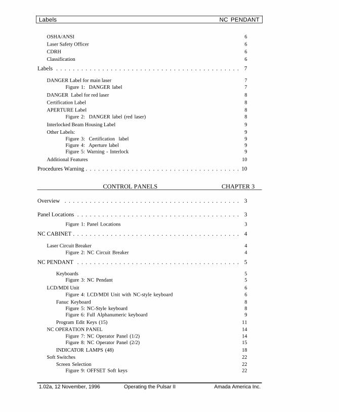
OSHA/ANSI 6
Laser Safety Officer 6
CDRH 6
Classification 6
Labels . . . . . . . . . . . . . . . . . . . . . . . . . . . . . . . . . . . . . . . . . . . . 7
DANGER Label for main laser 7Figure 1: DANGER label 7
DANGER Label for red laser 8
Certification Label 8
APERTURE Label 8Figure 2: DANGER label (red laser) 8
Interlocked Beam Housing Label 9
Other Labels: 9Figure 3: Certification label 9Figure 4: Aperture label 9Figure 5: Warning - Interlock 9
Additional Features 10
Procedures Warning . . . . . . . . . . . . . . . . . . . . . . . . . . . . . . . . . . . . . 10arning
CONTROL PANELS CHAPTER 3
Overview . . . . . . . . . . . . . . . . . . . . . . . . . . . . . . . . . . . . . . . . . . 3
Panel Locations . . . . . . . . . . . . . . . . . . . . . . . . . . . . . . . . . . . . . . . 3ns
Figure 1: Panel Locations 3
NC CABINET . . . . . . . . . . . . . . . . . . . . . . . . . . . . . . . . . . . . . . . . 4T
Laser Circuit Breaker 4Figure 2: NC Circuit Breaker 4
NC PENDANT . . . . . . . . . . . . . . . . . . . . . . . . . . . . . . . . . . . . . . . 5T
Keyboards 5Figure 3: NC Pendant 5
LCD/MDI Unit 6Figure 4: LCD/MDI Unit with NC-style keyboard 6
Fanuc Keyboard 8Figure 5: NC-Style keyboard 8Figure 6: Full Alphanumeric keyboard 9
Program Edit Keys (15) 11NC OPERATION PANEL 14
Figure 7: NC Operator Panel (1/2) 14Figure 8: NC Operator Panel (2/2) 15
INDICATOR LAMPS (48) 18Soft Switches 22
Screen Selection 22Figure 9: OFFSET Soft keys 22
1.02a, 12 November, 1996 Operating the Pulsar II Amada America Inc.
Labels NC PENDANT
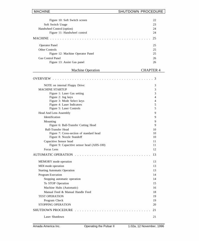
Figure 10: Soft Switch screen 22
Soft Switch Usage 23Handwheel Control (option) 24
Figure 11: Handwheel control 24
MACHINE . . . . . . . . . . . . . . . . . . . . . . . . . . . . . . . . . . . . . . . . . 25MACHINE
Operator Panel 25
Other Controls 25Figure 12: Machine Operator Panel 25
Gas Control Panel 26Figure 13: Assist Gas panel 26
Machine Operation CHAPTER 4
OVERVIEW . . . . . . . . . . . . . . . . . . . . . . . . . . . . . . . . . . . . . . . . . 3OVERVIEW
NOTE on internal Floppy Drive: 3MACHINE STARTUP 3
Figure 1: Laser Gas setting 3Figure 2: Jog keys 4Figure 3: Mode Select keys 4Figure 4: Laser Indicators 5Figure 5: Laser Controls 5
Head And Lens Assembly 9Identification 9
Mounting 9Figure 6: Ball-Transfer Cutting Head 9
Ball-Transfer Head 10Figure 7: Cross-section of standard head 10Figure 8: Nozzle Standoff 10
Capacitive Sensor head 11Figure 9: Capacitive sensor head (AHS-100) 11
Focus Lens 12
AUTOMATIC OPERATION . . . . . . . . . . . . . . . . . . . . . . . . . . . . . . . 13AUTOMATIC OPERATION
MEMORY mode operation 13
MDI mode operation 13
Starting Automatic Operation 13
Program Execution 14Stopping automatic operation 14
To STOP Operation 15
Machine Halts (Automatic) 16
Manual Feed & Manual Handle Feed 18TEST OPERATION 19
Program Check 19STOPPING OPERATION 20
SHUTDOWN PROCEDURE . . . . . . . . . . . . . . . . . . . . . . . . . . . . . . . 21SHUTDOWN PROCEDURE
Laser Shutdown 21
Amada America Inc. Operating the Pulsar II 1.02a, 12 November, 1996
MACHINE SHUTDOWN PROCEDURE
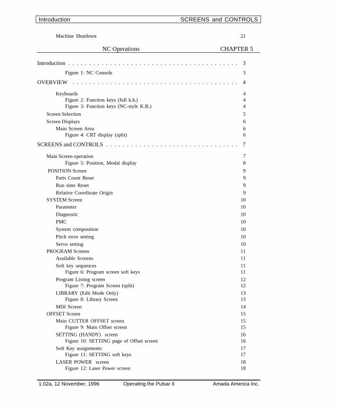
Machine Shutdown 21
NC Operations CHAPTER 5
Introduction . . . . . . . . . . . . . . . . . . . . . . . . . . . . . . . . . . . . . . . . . 3
Figure 1: NC Console 3
OVERVIEW . . . . . . . . . . . . . . . . . . . . . . . . . . . . . . . . . . . . . . . . 4
Keyboards 4Figure 2: Function keys (full k.b.) 4Figure 3: Function keys (NC-style K.B.) 4
Screen Selection 5
Screen Displays 6Main Screen Area 6
Figure 4: CRT display (split) 6
SCREENS and CONTROLS . . . . . . . . . . . . . . . . . . . . . . . . . . . . . . . . 7d CONTROLS
Main Screen operation 7Figure 5: Position, Modal display 8
POSITION Screen 9Parts Count Reset 9
Run time Reset 9
Relative Coordinate Origin 9SYSTEM Screen 10
Parameter 10
Diagnostic 10
PMC 10
System composition 10
Pitch error setting 10
Servo setting 10PROGRAM Screens 11
Available Screens 11
Soft key sequences 11Figure 6: Program screen soft keys 11
Program Listing screen 12Figure 7: Program Screen (split) 12
LIBRARY (Edit Mode Only) 13Figure 8: Library Screen 13
MDI Screen 14OFFSET Screen 15
Main CUTTER OFFSET screen 15Figure 9: Main Offset screen 15
SETTING (HANDY) screen 16Figure 10: SETTING page of Offset screen 16
Soft Key assignments 17Figure 11: SETTING soft keys 17
LASER POWER screen 18Figure 12: Laser Power screen 18
1.02a, 12 November, 1996 Operating the Pulsar II Amada America Inc.
Introduction SCREENS and CONTROLS
Work Coordinate System screen 19
Macro Variables display 19MESSAGE Screen 20
GRAPHIC Screen 20
HELP Screens 21Figure 13: Initial Help Menu 21
Alarms help 22Figure 14: Alarm Detail menu 22
Operations help 23Figure 15: Operations Help menu 23
Parameters help 24Figure 16: Parameters Help menu 24
ADVANCED OPERATIONS . . . . . . . . . . . . . . . . . . . . . . . . . . . . . . . 25ADVANCED OPERATIONS
Changing Parameters 25Parameter Write Enable 25
Parameter Write Disable 25Figure 17: SETTING (HANDY) screen 25
The PARAMETER screen 26
Altering a parameter 26Communications Parameters 26
Parameter Edit soft keys 27
2. Data Output to a floppy disk 282-1 NC parameters 28
2-2 Pitch error data 28
2-3 Cutter compensation ( tool offset) 28
2-4 PMC Parameter data 283. Data Input from a floppy disk 29
3-1 NC parameter 29
3-2 Pitch error data 29
3-3 Cutter compensation data ( tool offset ) 29
3-4 PMC Parameter data ( Keep relay 17 bit 1 = 1 ) 29
Program Storage and editing CHAPTER 6
Overview . . . . . . . . . . . . . . . . . . . . . . . . . . . . . . . . . . . . . . . . . . . 3Overview
Preparing to Edit . . . . . . . . . . . . . . . . . . . . . . . . . . . . . . . . . . . . . . . 3Preparing to Edit
Program Selection 4
Program Handling 5Creating a Program 5
Program Delete 5
Edit Procedures . . . . . . . . . . . . . . . . . . . . . . . . . . . . . . . . . . . . . . . . 6Edit Procedures
Cursor Forward 6
Line Forward 6
Page Forward 6
Amada America Inc. Operating the Pulsar II 1.02a, 12 November, 1996
ADVANCED OPERATIONS Edit Procedures

Return to Top of Program 6
Word Search 7
Word Change 7
Inserting Word(s) 7
Word Deletion 8Figure 1: “delete to word ” before 9Figure 2: “delete to word ” after 9
EXPANDED TAPE EDIT FUNCTION 10Copying a Program 11
Moving a Program 13
Merging Programs 14
Search and Replace 15BACKGROUND EDIT 18
Starting a Background Edit 18
Finishing a Background Edit 18
Loading and Saving Programs . . . . . . . . . . . . . . . . . . . . . . . . . . . . . . . 19Saving Programs
Setup 19Figure 3: Soft-Key sequence 19
Directory of a Floppy Disk 20
From NC to Floppy 20Figure 4: Keys for Read, Punch, etc. 20
Renaming a program on floppy 21Figure 5: Keys for File Name/Number 21
From Floppy to NC 22Figure 6: Extended keys for READ, PUNCH 22
File Search 23Figure 7: Soft Keys for File Search 23
Cutting Data Screens CHAPTER 7
OVERVIEW . . . . . . . . . . . . . . . . . . . . . . . . . . . . . . . . . . . . . . . . 3
Screen Selection 3Soft Keys 4
Selecting Full/Split Screen 4Figure 1: Cut Cond. + Laser Info 4
LASER INFORMATION Screen . . . . . . . . . . . . . . . . . . . . . . . . . . . . . 5RMATION Screen
Display Operation 5Laser Information screen items 6Figure 2: Material List with Laser Information 6
On-Line Adjustments 8Preparation 8
Adjustments 9
Cutting Data Library . . . . . . . . . . . . . . . . . . . . . . . . . . . . . . . . . . . . 10Library
Overview 10Figure 3: Material selection in program 11
1.02a, 12 November, 1996 Operating the Pulsar II Amada America Inc.
Loading and Saving Programs Cutting Data Library
CUTTING CONDITION Screen . . . . . . . . . . . . . . . . . . . . . . . . . . . . . 12CUTTING CONDITION Screen
Display Operation 12Figure 4: Cut Condition screen 12
Items on Cutting Condition screen 13Editing Cut Conditions 16
Selection of cut condition 16
Editing Data 17
Data storage 17
PIERCE CONDITION Screen . . . . . . . . . . . . . . . . . . . . . . . . . . . . . . . 18PIERCE CONDITION Screen
Figure 5: Piercing screen 18
Display Operation 19Display items 19
Setting Operation 21Editing Data 21
EDGE CONDITION Screen . . . . . . . . . . . . . . . . . . . . . . . . . . . . . . . . 24EDGE CONDITION Screen
Figure 6: Edge Condition screen 24
Display Operation 25Display items 25
Editing EDGE conditions 27Navigation 27
Editing 27
Data storage 27Using EDGE Control 28
Figure 7: Measurement of EDGE angles 28
Approach Control 29Figure 8: Edge screen 29Figure 9: EDGE setup 29
MATERIAL LIST Screen . . . . . . . . . . . . . . . . . . . . . . . . . . . . . . . . . 30MATERIAL LIST Screen
Display Operation 30Figure 10: Material List screen 30
Display Items 31Material List screen items 31
Cutting Data File Operations 32Selecting a material 32
Creating New Material Name 33
Rename a material 33
Copy to new file 34
Deleting a material name 34
Search of material name 35
PARAMETER SETTING Screen . . . . . . . . . . . . . . . . . . . . . . . . . . . . . 36PARAMETER SETTING Screen
Figure 11: Laser Parameters screen 36
Setting Operation 37
MACHINE ALARMS Screen . . . . . . . . . . . . . . . . . . . . . . . . . . . . . . . 37MACHINE ALARMS Screen
Amada America Inc. Operating the Pulsar II 1.02a, 12 November, 1996
CUTTING CONDITION Screen MACHINE ALARMS Screen
Display Operation 37
CUTTING DATA TRANSFER . . . . . . . . . . . . . . . . . . . . . . . . . . . . . . 38ATA TRANSFER
MAINTENANCE CHAPTER 8
Daily Maintenance . . . . . . . . . . . . . . . . . . . . . . . . . . . . . . . . . . . . . 2nance
Cleaning 2
Noise 2
Chiller 2
Laser Gas Supply 2
Assist Gas Supply 2
Air System 3Figure 1: Air, Gas Panel 3
Laser Oscillator 4Figure 2: Laser Blower Oil Check 4Figure 3: Laser Cabinet 4
Periodic Maintenance . . . . . . . . . . . . . . . . . . . . . . . . . . . . . . . . . . . . 5tenance
Schedule 1 5Weekly Maintenance 5
Monthly Maintenance 5
Every Two Months 5
Every Four Months 5
Every Six Months 5
Every twelve Months 6
Every 24 Months 6
Every 36 Months 6
Every 48 Months 6Schedule 2 6
Every 200 hours 6
Every 1000 hours 6
Every 1500 hours 6
Every 3000 hours 6
Every 10000 hours 6
Every 12000 hours 6
Lubrication . . . . . . . . . . . . . . . . . . . . . . . . . . . . . . . . . . . . . . . . . 7
Lubricants 7
Covers and labels 8Figure 4: Covers and Labels 8Figure 5: X-Carriage lube points 8
Lube Points 9Figure 6: Lubrication points 9
Cleaning . . . . . . . . . . . . . . . . . . . . . . . . . . . . . . . . . . . . . . . . . . . 10
Focus Lens 10
1.02a, 12 November, 1996 Operating the Pulsar II Amada America Inc.
CUTTING DATA TRANSFER Cleaning
Cutting Nozzle 11
Sensor (AHS 100) 11
Bend Mirror 11
NC Cabinet Air Filters. 11Figure 7: Bend Mirror 11
Replacements . . . . . . . . . . . . . . . . . . . . . . . . . . . . . . . . . . . . . . . 12Replacements
Servicing the Laser Blower 12Adding Oil 12
Changing Oil 12Figure 8: Blower service points 12
Servicing the Laser Vacuum Pump 13Figure 9: Laser Vacuum Pump 13
Air System 14Adjusting lube rate 14
Beam Purge Air 14
Compressed Air Filter 14Figure 10: Air filter, Mist separator 14
Laser Gas bottle 15
NC Memory Backup Cell 15
Optical System . . . . . . . . . . . . . . . . . . . . . . . . . . . . . . . . . . . . . . . 16Optical System
Interlocks 16Beam Path 17
Figure 11: Locations of mirrors (1500 Watt system) 17
Centering the Nozzle . . . . . . . . . . . . . . . . . . . . . . . . . . . . . . . . . . . 18Centering the Nozzle
Figure 12: Adjustment Direction 18Figure 13: Un-centered nozzle 18
Setup 19
Procedure 19Figure 14: Sparks after centering nozzle 19
Adjusting Focus Position . . . . . . . . . . . . . . . . . . . . . . . . . . . . . . . . . . 20Adjusting Focus Position
Cutting Test Setup 20Figure 15: Focus Test 20
Adjustment Procedure 21
Maintenance Program Listings . . . . . . . . . . . . . . . . . . . . . . . . . . . . . . . 22Maintenance Program Listings
ALARMS CHAPTER 9
Overview . . . . . . . . . . . . . . . . . . . . . . . . . . . . . . . . . . . . . . . . . . . 3Overview
ALARM DISPLAYS . . . . . . . . . . . . . . . . . . . . . . . . . . . . . . . . . . . . 3ALARM DISPLAYS
MACHINE ALARMS . . . . . . . . . . . . . . . . . . . . . . . . . . . . . . . . . . . . 3MACHINE ALARMS
Amada America Inc. Operating the Pulsar II 1.02a, 12 November, 1996
Replacements MACHINE ALARMS
Height Sensor Alarms . . . . . . . . . . . . . . . . . . . . . . . . . . . . . . . . . . . . 7Alarms
AHC Alarms (Option, Altair only) . . . . . . . . . . . . . . . . . . . . . . . . . . . . . 8(Option, Altair only)
NC Alarms . . . . . . . . . . . . . . . . . . . . . . . . . . . . . . . . . . . . . . . . . 9
Program Error (P/S alarms) . . . . . . . . . . . . . . . . . . . . . . . . . . . . . . . . . 9r (P/S alarms)
Background Edit Alarms (BP/S) . . . . . . . . . . . . . . . . . . . . . . . . . . . . . . 21dit Alarms (BP/S)
Absolute Pulse Code (APC) Alarms . . . . . . . . . . . . . . . . . . . . . . . . . . . . 22e Code (APC) Alarms
Serial Pulse Coder (SPC) alarms . . . . . . . . . . . . . . . . . . . . . . . . . . . . . . 23oder (SPC) alarms
Servosystem alarms . . . . . . . . . . . . . . . . . . . . . . . . . . . . . . . . . . . . . 23alarms
Overtravel alarms . . . . . . . . . . . . . . . . . . . . . . . . . . . . . . . . . . . . . . 26rms
Overheat alarms . . . . . . . . . . . . . . . . . . . . . . . . . . . . . . . . . . . . . . . 26ms
System alarms . . . . . . . . . . . . . . . . . . . . . . . . . . . . . . . . . . . . . . . . 28s
Laser alarms . . . . . . . . . . . . . . . . . . . . . . . . . . . . . . . . . . . . . . . . . 29
INDEX CHAPTER 10
ADDITIONAL INFORMATION CHAPTER 11
NOTE on internal Floppy Drive: 1
1.02a, 12 November, 1996 Operating the Pulsar II Amada America Inc.
Height Sensor Alarms Laser alarms

Notes
Amada America Inc. Operating the Pulsar II 1.02a, 12 November, 1996
Laser alarms Laser alarms

This page intentionally left blank

Chapter 1
DESCRIPTION
Amada America, Inc. Operating the Pulsar II 1.02a, 12 November, 1996

Figure 1: Machine Overview
1 - 2
Amada America, Inc. Operating the Pulsar II 1.02a, 12 November, 1996
OVERVIEW
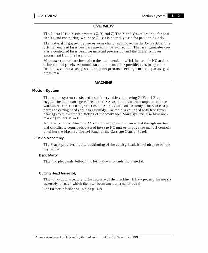
The Pulsar II is a 3-axis system. (X, Y, and Z) The X and Y-axes are used for posi-tioning and contouring, while the Z-axis is normally used for positioning only.
The material is gripped by two or more clamps and moved in the X-direction. Thecutting head and laser beam are moved in the Y-direction. The laser generator cre-ates a controlled laser beam for material processing, and the chiller removesexcess heat from the laser unit.
Most user controls are located on the main pendant, which houses the NC and ma-chine control panels. A control panel on the machine provides certain operatorfunctions, and an assist gas control panel permits checking and setting assist gaspressures.
MACHINE
Motion System
The motion system consists of a stationary table and moving X, Y, and Z-car-riages. The main carriage is driven in the X-axis. It has work clamps to hold theworksheet. The Y- carriage carries the Z-axis and head assembly. The Z-axis sup-ports the cutting head and lens assembly. The table is equipped with free-travelbearings to allow smooth motion of the worksheet. Some systems also have non-marking rollers as well.
All three axes are driven by AC servo motors, and are controlled through motionand coordinate commands entered into the NC unit or through the manual controlson either the Machine Control Panel or the Carriage Control Panel.
Z-Axis Assembly
The Z-axis provides precise positioning of the cutting head. It includes the follow-ing items:
Bend Mirror
This two piece unit deflects the beam down towards the material.
Cutting Head Assembly
This removable assembly is the aperture of the machine. It incorporates the nozzleassembly, through which the laser beam and assist gases travel.
For further information, see page 4-9.
1 - 3
Amada America, Inc. Operating the Pulsar II 1.02a, 12 November, 1996
OVERVIEW Motion System
SAFETY FEATURES
Laser Warning Light
This light will illuminate and rotate when the shutter is opened and the CO2 beamis released.
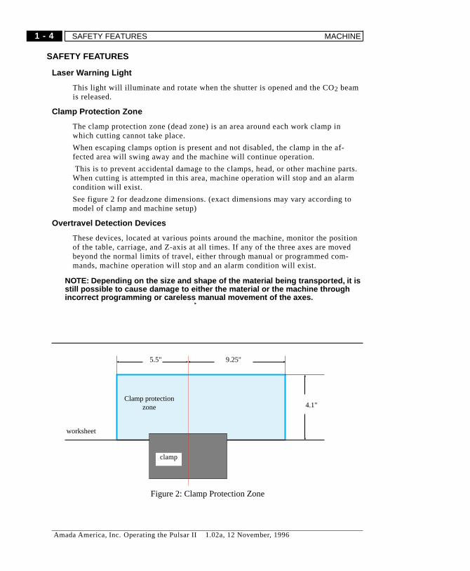
Clamp Protection Zone
The clamp protection zone (dead zone) is an area around each work clamp inwhich cutting cannot take place.
When escaping clamps option is present and not disabled, the clamp in the af-fected area will swing away and the machine will continue operation.
This is to prevent accidental damage to the clamps, head, or other machine parts.When cutting is attempted in this area, machine operation will stop and an alarmcondition will exist.
See figure 2 for deadzone dimensions. (exact dimensions may vary according tomodel of clamp and machine setup)
Overtravel Detection Devices
These devices, located at various points around the machine, monitor the positionof the table, carriage, and Z-axis at all times. If any of the three axes are movedbeyond the normal limits of travel, either through manual or programmed com-mands, machine operation will stop and an alarm condition will exist.
� NOTE: Depending on the size and shape of the material being transported, it isstill possible to cause damage to either the material or the machine throughincorrect programming or careless manual movement of the axes.
worksheet
5.5"
Clamp protectionzone 4.1"
9.25"
clamp
Figure 2: Clamp Protection Zone
1 - 4
Amada America, Inc. Operating the Pulsar II 1.02a, 12 November, 1996
SAFETY FEATURES MACHINE
OTHER FEATURES
Foot Switch
Stepping on the foot switch once will cause the work clamps to open or close, de-pending on their current status. Stepping on the switch again will return theclamps to their original position. The machine is interlocked against operationwhile the clamps are open.
Gauge Pins
These pins are used to locate the worksheet at the X, Y origin when loading it (theworksheet) into the clamps. The machine is interlocked against operation whilethe block is raised.
Work Clamps
Two styles of clamps are available: Fixed, manually-adjustable clamps, and “es-caping” clamps. Both styles are pneumaticly actuated, attached to the carriage andare used to hold the worksheet.
The non-escaping clamps can be positioned anywhere along the carriage, and arerelocated by loosening the clamp levers. Four quick- disconnect air ports are lo-cated along the carriage for easier connections.
When the head gets too close to an escaping clamp, the clamp will release the ma-terial and turn out of the way. When the head moves away from the clamp, itswings back into position and re-grips the material.
The escaping clamps can also be positioned along the carriage, but must be spacedfairly evenly so that any two can hold the worksheet while the third has moved toclear the cutting head. Also, it must not be possible for two escaping clamps to bein the release zone at the same time.
Work Chute
The work chute is opened and closed by air pressure. When the proper NC com-mands are given, the chute will open and/or close to permit a finished part orscrap material to drop from the cutting area. The chute measures 21.5" in the X-di-rection, and extends the entire Y-axis stroke. The machine is interlocked againstoperation while the chute is open.
Scrap Box
This box collects small scrap and debris created during cutting operation. The ma-chine is interlocked against operation when the access door to this box is open.
1 - 5
Amada America, Inc. Operating the Pulsar II 1.02a, 12 November, 1996
MACHINE OTHER FEATURES
Work Holders
These devices are air driven and hold the material stationary during programmedrepositioning (G25).
Assist Gas Block
This block has quick-disconnect ports for several different types of gases that maybe used to enhance the laser cutting operation. Ports are selected by NC code andthe ports are labeled appropriately.
CONTROL PANELS
The Machine, NC, and Carriage control panels are described in detail in chapter 3.
LASER
This unit creates the CO2 laser beam used during the cutting process. By directingan Radio Frequency (RF) discharge through a circulating mixture of Helium,Carbon Dioxide, and Nitrogen gases, this unit can output a laser beam at a wave-length of 10.6 microns. This unit includes the Solid State laser, which generates avisible (red) laser light that can be used for program checks and to assure the op-erator that the CO2 beam is not being output through the cutting head.
SUPPORT EQUIPMENT
Chiller
This device circulates water to the Laser unit to remove the excess heat generatedby the laser chamber during the creation of the laser beam. It can be located re-motely to the machine.
Air Dryer (option)
This device insures that the air going to the Output Coupler Cooler and the airused for purging the beam delivery tube is as dry as possible.
Dust Collector
The dust collector draws dust and cutting effluent from the cutting zone into a bag-type filter system. The standard dust collector is not intended to handle emissionsfrom cutting non-metallic materials such as Kevlar or PVC plastics.
1 - 6
Amada America, Inc. Operating the Pulsar II 1.02a, 12 November, 1996
CONTROL PANELS LASER

Chapter 2
SAFETY
Amada America, Inc. Operating the Pulsar II 1.02a, 12 November, 1996

Notes
2 - 2
Amada America, Inc. Operating the Pulsar II 1.02a, 12 November, 1996
GENERAL PRECAUTIONS
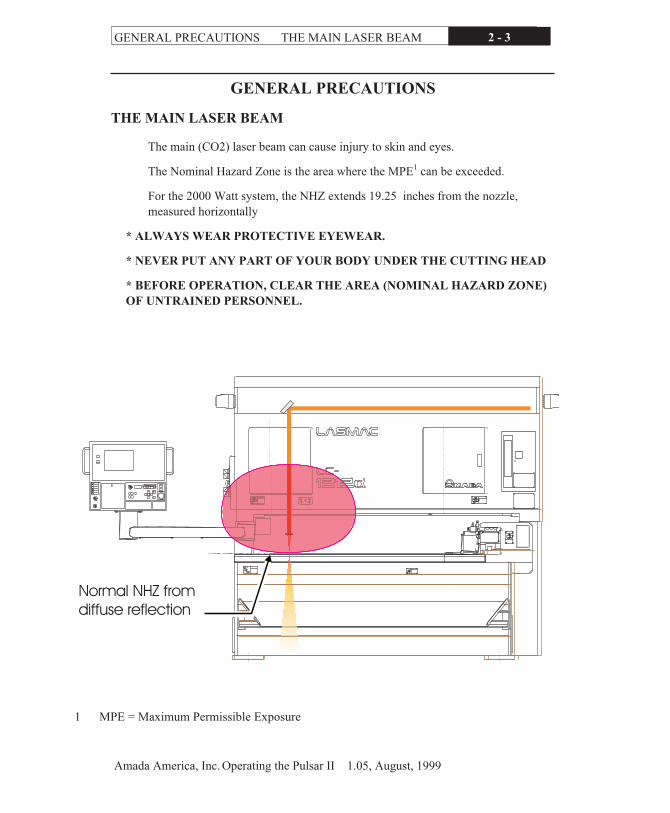
THE MAIN LASER BEAM
The main (CO2) laser beam can cause injury to skin and eyes.
The Nominal Hazard Zone is the area where the MPE1 can be exceeded.
For the 2000 Watt system, the NHZ extends 19.25 inches from the nozzle,
measured horizontally
* ALWAYS WEAR PROTECTIVE EYEWEAR.
* NEVER PUT ANY PART OF YOUR BODY UNDER THE CUTTING HEAD
* BEFORE OPERATION, CLEAR THE AREA (NOMINAL HAZARD ZONE)
OF UNTRAINED PERSONNEL.
Amada America, Inc. Operating the Pulsar II 1.05, August, 1999
GENERAL PRECAUTIONS THE MAIN LASER BEAM 2 - 3
Normal NHZ fromdiffuse reflection
1 MPE = Maximum Permissible Exposure

MACHINE LASER APERTURE
During normal operation, the machine aperture, or point at which the laser beamcan exit the machine, is the nozzle in the cutting head. If it is necessary to placeany part of your body under the cutting head for any reason, ensure the He-Ne la-ser is turned on first. When the He-Ne is on, the shutter is closed by interlocksand the path of the CO2 beam is blocked by the He-Ne beam bender.
THE RED AIMING BEAM
The red beam is much less powerful and much less dangerous than the main laserbeam. Casual viewing of the light or its reflection (briefly) is not considered ex-tremely hazardous. However, DO NOT STARE into the beam or its directreflection. This can cause permanent eye damage.
SECONDARY RADIATION
Some substances, such as brick or concrete, can emit ultraviolet radiation whenstruck by the laser beam. This invisible U.V. light, as well as some intense visiblelight, is called SECONDARY RADIATION (light radiation). It can pass directlythrough clear safety glasses, causing the same kind of discomfort and possibledamage as from watching arc welding.
� NEVER LOOK DIRECTLY AT THE POINT AT WHICH THE BEAM COMES INTOCONTACT WITH THE MATERIAL.
� IF VIEWING IS REQUIRED FOR TROUBLESHOOTING OR SERVICE, WEARWELDING PROTECTIVE EYEWEAR, (AWS) GRADE 5 OR BETTER.
See the ANSI publication Z136.1 section 7.4.2 (UV and Visible Radiation) for fur-ther information.
Fire
Flammable materials will ignite when struck by the laser beam. After cutting suchmaterials, immediately dispose of the scraps. Clear the area of such materialswhen performing any beam alignment procedures.
Poisonous Vapors
Some materials (such as coated metals, plastics, and fabric) emit harmful vaporswhen laser cut. Ensure the work area is properly ventilated.
Always ensure that the work area is well ventilated -Never breathe fumes from the cutting process.
See the ANSI publication Z136.1 section 7.3 (Laser Generated Air Contaminants)for further information.
2 - 4
Amada America, Inc. Operating the Pulsar II 1.02a, 12 November, 1996
Poisonous Vapors GENERAL PRECAUTIONS
HIGH-VOLTAGE POWER
High-voltage power is used in the machine to create the laser beam. These arele-thal voltages, and are easily thegreatest danger associated with laser equipment.Even after power is shut off, a dangerous electrical charge may remain for severalminutes.
� Do NOT open the cover panels unless you are a trained service person, or atthe direction of Amada’s Service department.
� Always turn the disconnect OFF before opening cabinets.
� If electrical problems occur, please contact the A.E.S.I. Laser Departmentrather than attempting to correct them yourself.
MOVEMENT OF WORKSHEETS
Worksheets may extend from EITHER END of the table during operation. Beforestarting the machine, ensure the area is clear of all uninformed observers.
G04 FUNCTION (DWELL TIME)
When using the command G04, the machine will stop for the time determined bythe G04 and automatically continue operation. Refer to the Programming Manualfor further information.
2 - 5
Amada America, Inc. Operating the Pulsar II 1.02a, 12 November, 1996
GENERAL PRECAUTIONS G04 FUNCTION (DWELL TIME)
FEDERAL REGULATIONS
OSHA/ANSI
The OSHA organization looks to certain standards organizations for proceduresand recommendations. For laser equipment, ANSI Z136.1 is called out, which pro-vides various requirements and recommendations. One of the requirements is for aLaser Safety Operator.
Laser Safety Officer
According to ANSI Z136.1-1993 section 1.3, “an individual shall be designatedthe Laser Safety Officer (LSO) with the authority and responsibility to monitorand enforce the control of laser hazards...”
The Customer is responsible to comply with the OSHA/ANSI standards.
CDRH
The Federal Government has created an agency of the Food and Drug Administra-tion know as the Center for Devices and Radiological Health (CDRH). It is thepurpose of this agency to establish guidelines for all lasers and/or laser systemssold in the United States. These guidelines are listed in the Code of Federal Regu-lations, title 21, chapter I, sub-chapter J, as applicable. It is in accordance withthe guidelines that the following information is provided.
Classification
The laser system, as produced by U.S. Amada, Ltd., also complies with all regula-tions. In addition to all features provided by FANUC, U.S. Amada, Ltd. hasprovided the following labels.
The Pulsar machines are rated as class IV laser systems. They have a continuouspower output of over 1500 watts at 10.6 micrometers. The red laser is a solid-stateunit rated class IIIa at a wavelength of 670 nanometers. The laser unit complieswith all Federal regulations as originally produced by the manufacturer, FANUCCorporation.
2 - 6
Amada America, Inc. Operating the Pulsar II 1.02a, 12 November, 1996
Classification FEDERAL REGULATIONS
Labels
The laser system, as produced by U.S. Amada, Ltd., also complies with all regula-tions. In addition to all features provided by FANUC, U.S. Amada, Ltd. hasprovided the following labels.
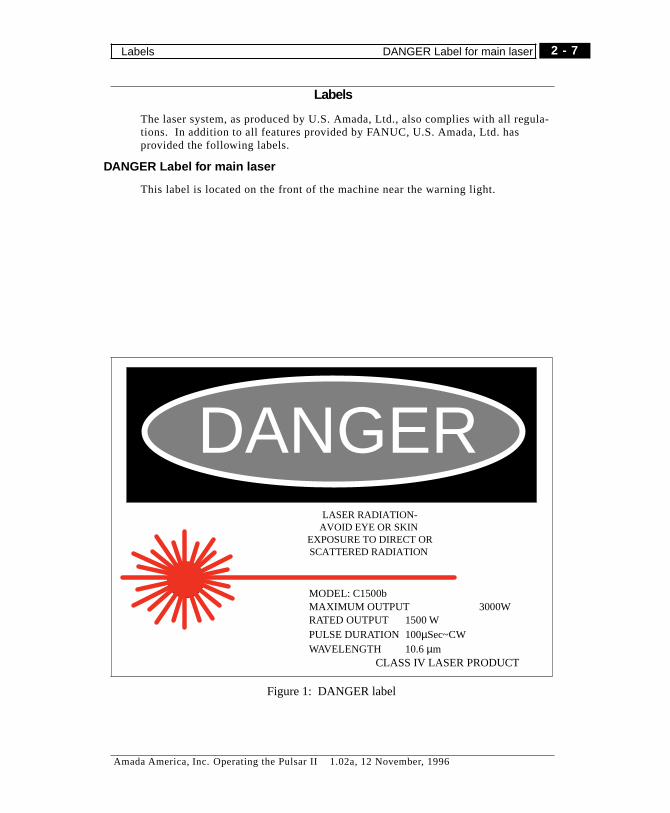
DANGER Label for main laser
This label is located on the front of the machine near the warning light.
DANGERLASER RADIATION-
AVOID EYE OR SKINEXPOSURE TO DIRECT ORSCATTERED RADIATION
MODEL: C1500bMAXIMUM OUTPUT 3000WRATED OUTPUT 1500 WPULSE DURATION 100µSec~CWWAVELENGTH 10.6µm
CLASS IV LASER PRODUCT
Figure 1: DANGER label
2 - 7
Amada America, Inc. Operating the Pulsar II 1.02a, 12 November, 1996
Labels DANGER Label for main laser
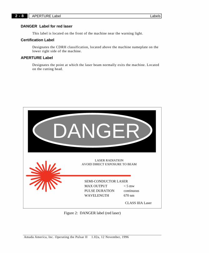
DANGER Label for red laser
This label is located on the front of the machine near the warning light.
Certification Label
Designates the CDRH classification, located above the machine nameplate on thelower right side of the machine.
APERTURE Label
Designates the point at which the laser beam normally exits the machine. Locatedon the cutting head.
DANGERLASER RADIATION
AVOID DIRECT EXPOSURE TO BEAM
SEMI-CONDUCTOR LASERMAX OUTPUT < 5 mwPULSE DURATION continuousWAVELENGTH 670 nm
CLASS IIIA Laser
Figure 2: DANGER label (red laser)
2 - 8
Amada America, Inc. Operating the Pulsar II 1.02a, 12 November, 1996
APERTURE Label Labels
Interlocked Beam Housing Label
Designates a cover or housing which is interlocked against machine operationwhen open. Located on the access cover for the Y-Z axes, and in other locations asneeded.
Reproductions of each of the above mentioned labels are pictured on these pages.
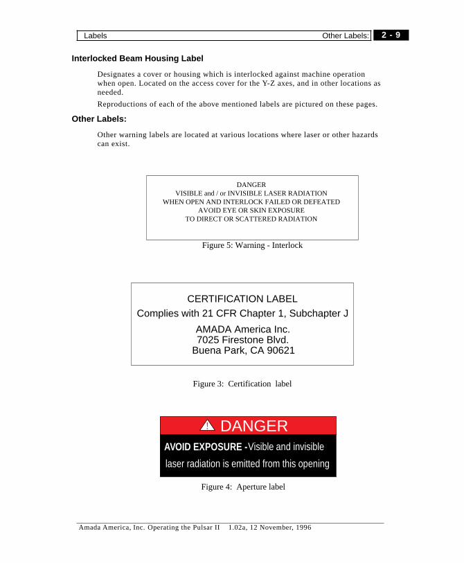
Other Labels:
Other warning labels are located at various locations where laser or other hazardscan exist.
CERTIFICATION LABELComplies with 21 CFR Chapter 1, Subchapter J
AMADA America Inc.7025 Firestone Blvd.
Buena Park, CA 90621
Figure 3: Certification label
! DANGERAVOID EXPOSURE -Visible and invisible
laser radiation is emitted from this opening
Figure 4: Aperture label
DANGERVISIBLE and / or INVISIBLE LASER RADIATION
WHEN OPEN AND INTERLOCK FAILED OR DEFEATEDAVOID EYE OR SKIN EXPOSURE
TO DIRECT OR SCATTERED RADIATION
Figure 5: Warning - Interlock
2 - 9
Amada America, Inc. Operating the Pulsar II 1.02a, 12 November, 1996
Labels Other Labels:
Additional Features
Access doors have redundant interlock protection, as required. All other requiredfeatures are unchanged as provided by the laser manufacturer, with the exceptionof an additional laser emission indicator, located on top of the machine.
ProceduresWarning
As has been explained above, exposure to the laser beam can be harmful. If the la-ser beam contacts your skin, it can cause serious cuts or burns. If the laser beamcontacts your eyes, it can cause temporary or permanent blindness. Since the laserbeam is radiated light, the CDRH frequently refers to the laser beam as radiation.The following statement is made is accordance with CDRH requirements:
Caution - use of controls or adjustments or performance of procedures other thanthose specified herein may result in hazardous radiation exposure.
2 - 10
Amada America, Inc. Operating the Pulsar II 1.02a, 12 November, 1996
Additional Features Procedures Warning

Chapter 3
CONTROL PANELS
Amada America, Inc. Operating the Pulsar II 1.02a, 12 November, 1996

Notes
3 - 2
Amada America, Inc. Operating the Pulsar II 1.02a, 12 November, 1996

Overview
This chapter describes the controls and indicators of each of the control panels onthe system. For operating instructions, see the specific chapters (machine opera-tion, NC operations, Cutting Data).
Panel Locations
Figure 1 shows the locations of major panels on the system.
1
2
3
4
5
7
8
6
Figure 1: Panel Locations
1 NC cabinet
2 Laser circuit breaker
3 NC Pendant
4 Assist Gas panel
5 HS-95 control panel (option)
6 Warning light
7 Machine Operator Panel
8 Clamp footswitch
3 - 3
Amada America, Inc. Operating the Pulsar II 1.02a, 12 November, 1996
Overview

NC CABINET
This Circuit Breaker NFB1 energizes NC and machine power. (see figure 2)Thisswitch must be “ON” to energize the NC. When you set the handle to OFF, youturn off all machine power. If a short circuit occurs in the NC system, circuitbreaker 1 will “Trip” and the machine power will be turned off.
� Caution:
If NFB1 trips, turn the service disconnect OFF and contact our service department.
Laser Circuit Breaker
Located on left side of the machine, on the end of the laser cabinet. It providespower to the laser, and should normally be left ON.
NFB1
Figure 2: NC Circuit Breaker(rear of machine)
3 - 4
Amada America, Inc. Operating the Pulsar II 1.02a, 12 November, 1996
Laser Circuit Breaker NC CABINET
NC PENDANT
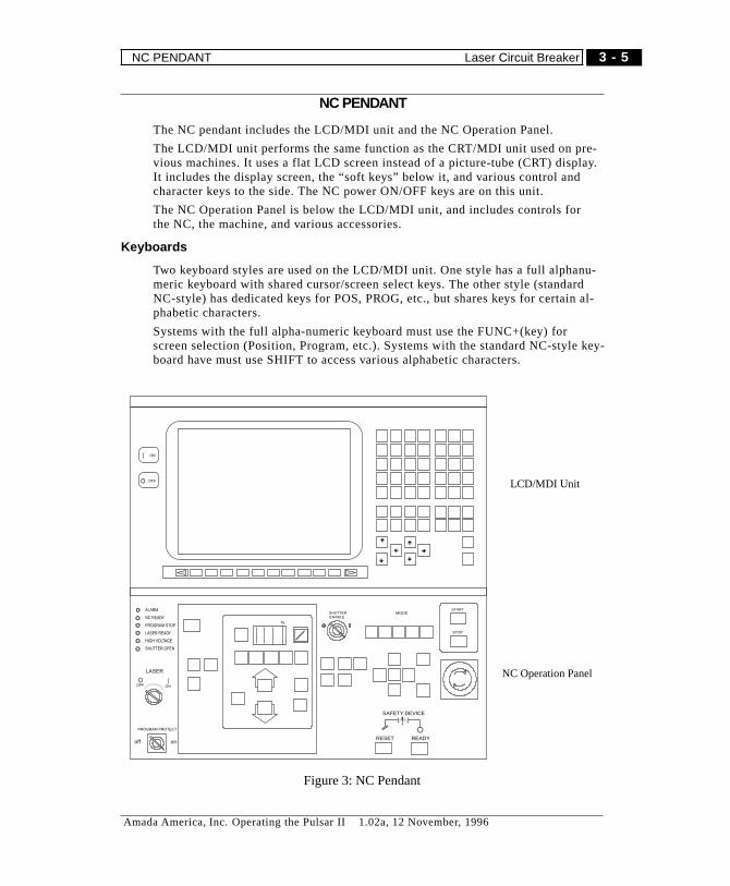
The NC pendant includes the LCD/MDI unit and the NC Operation Panel.
The LCD/MDI unit performs the same function as the CRT/MDI unit used on pre-vious machines. It uses a flat LCD screen instead of a picture-tube (CRT) display.It includes the display screen, the “soft keys” below it, and various control andcharacter keys to the side. The NC power ON/OFF keys are on this unit.
The NC Operation Panel is below the LCD/MDI unit, and includes controls forthe NC, the machine, and various accessories.
Keyboards
Two keyboard styles are used on the LCD/MDI unit. One style has a full alphanu-meric keyboard with shared cursor/screen select keys. The other style (standardNC-style) has dedicated keys for POS, PROG, etc., but shares keys for certain al-phabetic characters.
Systems with the full alpha-numeric keyboard must use the FUNC+(key) forscreen selection (Position, Program, etc.). Systems with the standard NC-style key-board have must use SHIFT to access various alphabetic characters.
ç è
é
ê
é
ê
ALARM
NC READY
PROGRAM STOP
LASER READY
HIGH VOLTAGE
SHUTTER OPEN
MODE
PROGRAM PROTECT
off on
%
ON
OFF
ONOFF
LASER
START
STOP
RESET READY
SAFETY DEVICE
SHUTTERENABLE
LCD/MDI Unit
NC Operation Panel
Figure 3: NC Pendant
3 - 5
Amada America, Inc. Operating the Pulsar II 1.02a, 12 November, 1996
NC PENDANT Laser Circuit Breaker
LCD/MDI Unit
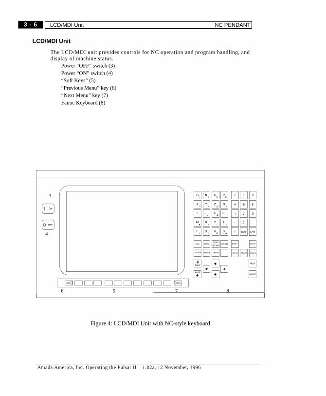
The LCD/MDI unit provides controls for NC operation and program handling, anddisplay of machine status.
Power “OFF” switch (3)Power “ON” switch (4)“Soft Keys” (5)“Previous Menu” key (6)“Next Menu” key (7)Fanuc Keyboard (8)
3
4
5 86 7
Figure 4: LCD/MDI Unit with NC-style keyboard
3 - 6
Amada America, Inc. Operating the Pulsar II 1.02a, 12 November, 1996
LCD/MDI Unit NC PENDANT
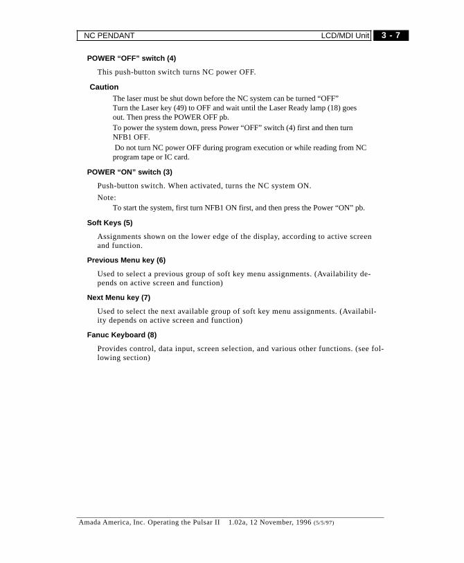
POWER “O FF” switch (4)
This push-button switch turns NC power OFF.
� CautionThe laser must be shut down before the NC system can be turned “OFF”Turn the Laser key (49) to OFF and wait until the Laser Ready lamp (18) goesout. Then press the POWER OFF pb.To power the system down, press Power “OFF” switch (4) first and then turnNFB1 OFF.Do not turn NC power OFF during program execution or while reading from NCprogram tapeor IC card.
POWER “O N” switc h (3)
Push-button switch. When activated, turns the NC system ON.
Note:To start the system, first turn NFB1 ON first, and then press the Power “ON” pb.
Soft Keys (5)
Assignments shown on the lower edge of the display, according to active screenand function.
Previous Menu key (6)
Used to select a previous group of soft key menu assignments. (Availability de-pends on active screen and function)
Next Menu key (7)
Used to select the next available group of soft key menu assignments. (Availabil-ity depends on active screen and function)
Fanuc Keyboard (8)
Provides control, data input, screen selection, and various other functions. (see fol-lowing section)
3 - 7
Amada America, Inc. Operating the Pulsar II 1.02a, 12 November, 1996 (5/5/97)
NC PENDANT LCD/MDI Unit
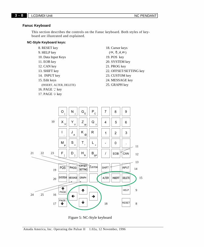
Fanuc Keyboard
This section describes the controls on the Fanuc keyboard. Both styles of key-board are illustrated and explained.
NC-Style Keyboard keys:
8. RESET key9. HELP key10. Data Input Keys11. EOB key12. CAN key13. SHIFT key14. INPUT key15. Edit keys
(INSERT, ALTER, DELETE)
16. PAGEñ key17. PAGEò key
18. Cursor keys(ï,ò,ñ,ð)
19. POS key20. SYSTEM key21. PROG key22. OFFSET/SETTING key23. CUSTOM key24. MESSAGE key25. GRAPH key
8
9
10
12
13
15
22
14
11
1817
24 16
21 23
20
19
25
Figure 5: NC-Style keyboard
3 - 8
Amada America, Inc. Operating the Pulsar II 1.02a, 12 November, 1996
LCD/MDI Unit NC PENDANT

Full Alphanumeric-style Keys:
U ] V )W
X Y Z: ;
#
%
$
HG
BA C D
E F
J K L
M N O P
Q R S T_ < > [
* ?
ALT
ALTER
CTRL
INSERT
DEL
DELETEFUNC
MMC
CNC
ESC
CUSTOM INPUT(
RESET
HELPPAGE
POS
PAGE
SYSTEM
GRAPHOFFSET
PROG
MESSAGE
CAN
- +0
7 8 9
4 5 6
1 2 3
SHIFTSPACE
EOB
268
15
13
15
14
22
1824
17, 20
16, 19
21
23
25
11
10
9
Figure 6: Full Alphanumeric keyboard
8. RESET key9. HELP key10. Data Input Keys11. EOB key12. CAN key13. SHIFT key14. INPUT key15. Edit keys
(INSERT, ALTER, DELETE)
16. PAGEñ /POS key17. PAGEò/SYSTEM key
18. Cursor keys (ï,ò,ñ,ð)See items 21, 22, 24, 25.
19. POS key20. SYSTEM key21.ñ/PROG key22.ï/OFFSET key23. ESC/CUSTOM key24.ò/MESSAGE key25.ð/GRAPH key26. FUNC key
3 - 9
Amada America, Inc. Operating the Pulsar II 1.02a, 12 November, 1996
NC PENDANT LCD/MDI Unit

RESET key (8)
Halts program execution, resets the NC system. Cancels any active NC alarms.
HELP key (9)
Provides assistance in MDI key operation, displays information on active NCalarm. (See page 5-21)
DATA INPUT keys (10)
Use to input alphanumeric characters (letters and numbers) and certain symbols.
EOB key (11)
Inserts an end-of-block character “;” into the key input buffer.
“SPACE” function not used.
CAN key (12)
Deletes characters or symbols from the key input buffer.The contents of the key input buffer are displayed on the display. The positionwhere the next character will go (Input standby position) is displayed as an under-bar “_”.When the program screen is active, the character immediately before “_” is can-celed (deleted from the buffer) by pressing BS/CAN. For other screens, data inputis all canceled.
Example: When the display of key input buffer is “N001X100Y_”, if you press theCAN key, Y is canceled and it becomes “N001X100_”.
SHIFT key (13)
Many of the data input keys have two characters on the face. To access the charac-ter on the lower corner of a key, press the shift key first. The symbol “^” isdisplayed on the screen, and the next key pressed will have the value of the sec-ond symbol or character.
INPUT key (14)
When you press any of the “Data input” keys, each character is held in the “key in-put buffer” temporarily and displayed on the display. Press INPUT key to activateor enter the keystrokes into a parameter or setting value. Not used in program edit-ing. (See INSERT, DEL, ALTER)
3 - 10
Amada America, Inc. Operating the Pulsar II 1.02a, 12 November, 1996
LCD/MDI Unit NC PENDANT
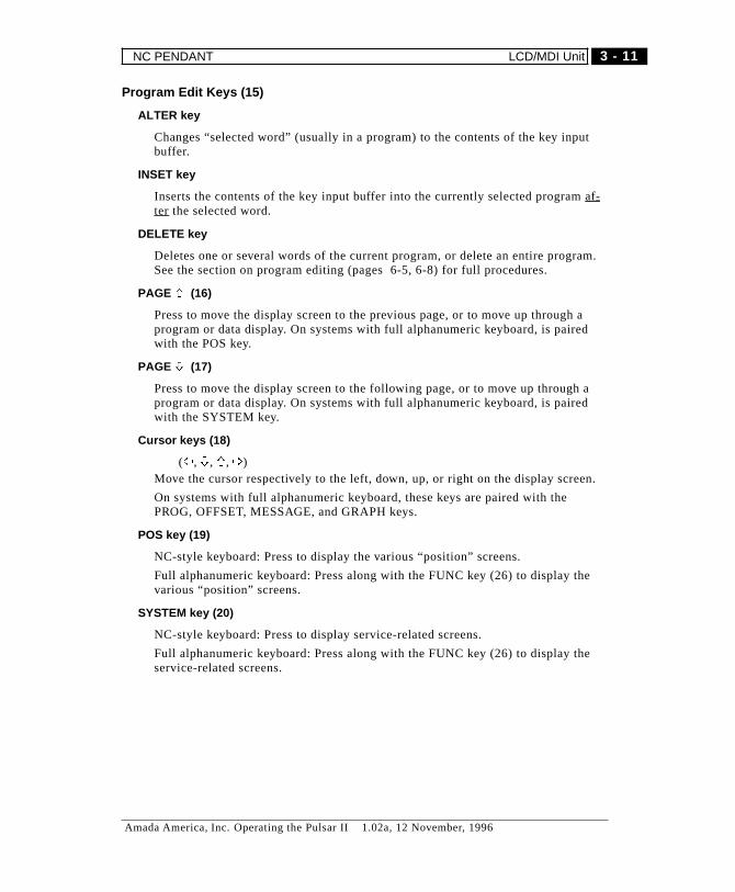
Program Edit Keys (15)
ALTER key
Changes “selected word” (usually in a program) to the contents of the key inputbuffer.
INSET key
Inserts the contents of the key input buffer into the currently selected programaf-ter the selected word.
DELETE key
Deletes one or several words of the current program, or delete an entire program.See the section on program editing (pages 6-5, 6-8) for full procedures.
PAGE ñ (16)
Press to move the display screen to the previous page, or to move up through aprogram or data display. On systems with full alphanumeric keyboard, is pairedwith the POS key.
PAGE ò (17)
Press to move the display screen to the following page, or to move up through aprogram or data display. On systems with full alphanumeric keyboard, is pairedwith the SYSTEM key.
Cursor keys (18)
(ï,ò,ñ,ð)Move the cursor respectively to the left, down, up, or right on the display screen.
On systems with full alphanumeric keyboard, these keys are paired with thePROG, OFFSET, MESSAGE, and GRAPH keys.
POS key (19)
NC-style keyboard: Press to display the various “position” screens.
Full alphanumeric keyboard: Press along with the FUNC key (26) to display thevarious “position” screens.
SYSTEM key (20)
NC-style keyboard: Press to display service-related screens.
Full alphanumeric keyboard: Press along with the FUNC key (26) to display theservice-related screens.
3 - 11
Amada America, Inc. Operating the Pulsar II 1.02a, 12 November, 1996
NC PENDANT LCD/MDI Unit
PROG key (21)
NC-style keyboard: Press to display program, edit, display, MDI operation, andmodel data.
Full alphanumeric keyboard: Press along with the FUNC key (26) to display therelated screens.
OFFSET key (22)
NC-style keyboard: Press to display cutter offset and/or work origin offset.
Full alphanumeric keyboard: Press along with the FUNC key (26) to display therelated screens.
CUSTOM key (23
Press to select the Cutting Data screens. The Cutting Data screens include theHelp screen and the Cutting Database screens. The most recently displayed Cut-ting Data screen is re-displayed. Pressing this key a second time blanks thedisplay. Pressing any key unblanks the screen.
MESSAGE key (24)
NC-style keyboard: Press to display the history of NC Alarms, operator messages,alarms.
Full alphanumeric keyboard: Press along with the FUNC key (26) to display therelated screens.
GRAPH key (25)
Selects the Graphic screen. The related functions are not supported on this ma-chine.
FUNC key (26)
Present on full alphanumeric keyboard only. Use with Cursor keys and Page Up,Page Down keys for screen selection.
3 - 12
Amada America, Inc. Operating the Pulsar II 1.02a, 12 November, 1996
LCD/MDI Unit NC PENDANT

Notes
3 - 13
Amada America, Inc. Operating the Pulsar II 1.02a, 12 November, 1996
NC PENDANT LCD/MDI Unit
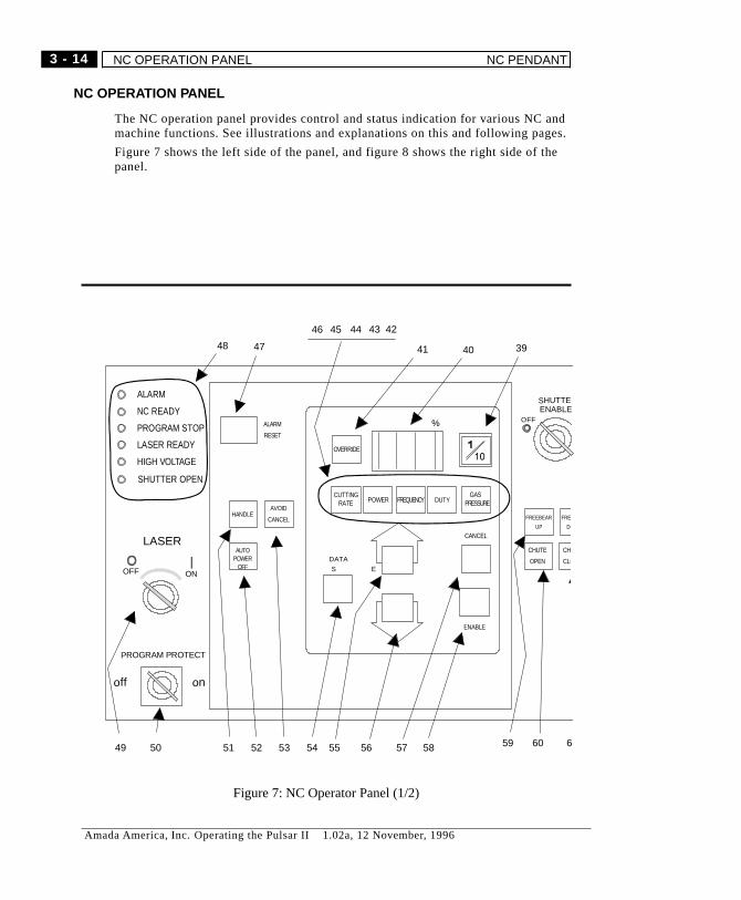
NC OPERATION PANEL
The NC operation panel provides control and status indication for various NC andmachine functions. See illustrations and explanations on this and following pages.
Figure 7 shows the left side of the panel, and figure 8 shows the right side of thepanel.
ALARM
NC READY
PROGRAM STOP
LASER READY
HIGH VOLTAGE
SHUTTER OPEN
SHUTTERENABLE
OFF
394041
4243444546
4748
49 50 51 52 53 54 55 56 57 58 59 60 6
PROGRAM PROTECT
off on
AVOID
CANCELHANDLE
AUTOPOWER
OFF
ALARM
RESET
OVERRIDE
CUTTINGRATE POWER FREQUENCY DUTY
GASPRESSURE
%
ENABLE
CANCEL
DATA
S E
FREE
DO
CHUTE
OPEN
CHU
CLO
FREEBEAR
UP
ONOFF
LASER
Figure 7: NC Operator Panel (1/2)
3 - 14
Amada America, Inc. Operating the Pulsar II 1.02a, 12 November, 1996
NC OPERATION PANEL NC PENDANT
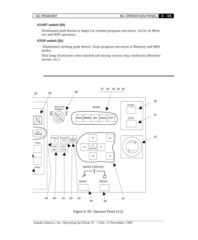
START switch (30)
Illuminated push button to begin (or resume) program execution. Active in Mem-ory and MDI operation.
STOP switch (31)
Illuminated latching push button. Stops program execution in Memory and MDImodes.
This lamp illuminates when latched and during various stop conditions.(Machinealarms, etc.)
O/T
RELEASE
-X
+X
-Y+Y
-Z
+Z
MODE
EDITMEMORY MDI MANUALRETRACT
SHUTTERENABLE
OFF ON
30
31
32
3334353637383940
59 60 61 62 63 64
GASPRESSURE
ENABLE
CANCEL
ZSENSORCANCEL
FREEBEAR
DOWN
CHUTE
OPEN
CHUTE
CLOSE
FREEBEAR
UP
START
STOP
RESET READY
SAFETY DEVICE
65 66
Figure 8: NC Operator Panel (2/2)
3 - 15
Amada America, Inc. Operating the Pulsar II 1.02a, 12 November, 1996
NC PENDANT NC OPERATION PANEL
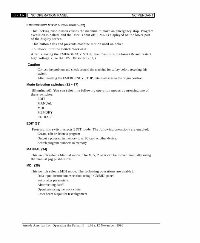
EMERGENCY STOP button switch (32)
This locking push-button causes the machine to make an emergency stop. Programexecution is halted, and the laser is shut off. EMG is displayed on the lower partof the display screen.
This button halts and prevents machine motion until unlocked.
To unlock, turn the switch clockwise.
After releasing the EMERGENCY STOP, you must turn the laser ON and restarthigh voltage. (See the H/V ON switch (52))
� CautionCorrect the problem and check around the machine for safety before resetting thisswitch.After resetting the EMERGENCY STOP, return all axes to the origin position.
Mode Selection switches (33 ~ 37)
(illuminated). You can select the following operation modes by pressing one ofthese switches:
EDITMANUALMDIMEMORYRETRACT
EDIT (33)
Pressing this switch selects EDIT mode. The following operations are enabled:Create, edit or delete a programOutput a program in memory to an IC card or other device.Search program numbers in memory
MANUAL (34)
This switch selects Manual mode. The X, Y, Z axis can be moved manually usingthe manual jog pushbuttons.
MDI (35)
This switch selects MDI mode. The following operations are enabled:Data input, instruction execution using LCD/MDI panel.Set or alter parameters.Alter “setting data”Opening/closing the work chuteLaser beam output for test/alignment
3 - 16
Amada America, Inc. Operating the Pulsar II 1.02a, 12 November, 1996
NC OPERATION PANEL NC PENDANT
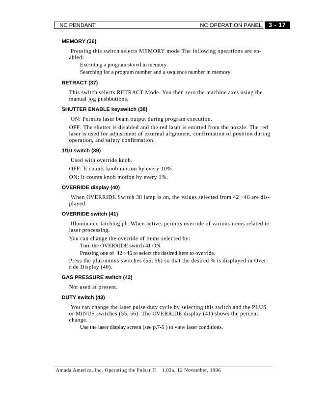
MEMORY (36)
Pressing this switch selects MEMORY mode The following operations are en-abled:
Executing a program stored in memory.Searching for a program number and a sequence number in memory.
RETRACT (37)
This switch selects RETRACT Mode. You then zero the machine axes using themanual jog pushbuttons.
SHUTTER ENABLE keyswitch (38)
ON: Permits laser beam output during program execution.
OFF: The shutter is disabled and the red laser is emitted from the nozzle. The redlaser is used for adjustment of external alignment, confirmation of position duringoperation, and safety confirmation.
1/10 switch (39)
Used with override knob.
OFF: It counts knob motion by every 10%.
ON: It counts knob motion by every 1%.
OVERRIDE display (40)
When OVERRIDE Switch 38 lamp is on, the values selected from 42 ~46 are dis-played.
OVERRIDE switch (41)
Illuminated latching pb. When active, permits override of various items related tolaser processing.
You can change the override of items selected by:Turn the OVERRIDE switch 41 ON.Pressing one of 42 ~46 to select the desired item to override.
Press the plus/minus switches (55, 56) so that the desired % is displayed in Over-ride Display (40).
GAS PRESSURE switch (42)
Not used at present.
DUTY switch (43)
You can change the laser pulse duty cycle by selecting this switch and the PLUSor MINUS switches (55, 56). The OVERRIDE display (41) shows the percentchange.
Use the laser display screen (see p.7-5 ) to view laser conditions.
3 - 17
Amada America, Inc. Operating the Pulsar II 1.02a, 12 November, 1996
NC PENDANT NC OPERATION PANEL
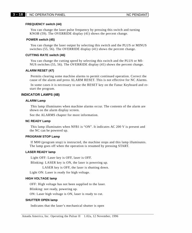
FREQUENCY switch (44)
You can change the laser pulse frequency by pressing this switch and turningKNOB (59). The OVERRIDE display (41) shows the percent change.
POWER switch (45)
You can change the laser output by selecting this switch and the PLUS or MINUSswitches (55, 56). The OVERRIDE display (41) shows the percent change.
CUTTING RATE switch (46)
You can change the cutting speed by selecting this switch and the PLUS or MI-NUS switches (55, 56). The OVERRIDE display (41) shows the percent change.
ALARM RESET (47)
Permits clearing some machine alarms to permit continued operation. Correct thecause of the alarm and press ALARM RESET. This is not effective for NC Alarms.
In some cases it is necessary to use the RESET key on the Fanuc Keyboard and re-start the program.
INDICATOR LAMPS (48)
ALARM Lamp
This lamp illuminates when machine alarms occur. The contents of the alarm areshown on the alarm display screen.
See the ALARMS chapter for more information.
NC READY Lamp
This lamp illuminates when NFB1 is “ON”. It indicates AC 200 V is present andthe NC can be powered up.
PROGRAM STOP Lamp
If M00 (program stop) is instructed, the machine stops and this lamp illuminates.The lamp goes off when the operation is resumed by pressing START.
LASER READY lamp
Light OFF: Laser key is OFF, laser is OFF.
Blinking: LASER key is ON, the laser is powering up.
LASER key is OFF, the laser is shutting down.
Light ON: Laser is ready for high voltage.
HIGH VOLTAGE lamp
OFF: High voltage has not been supplied to the laser.
Blinking: not ready, powering up.
ON: Laser high voltage is ON, laser is ready to cut.
SHUTTER OPEN lamp
Indicates that the laser’s mechanical shutter is open
3 - 18
Amada America, Inc. Operating the Pulsar II 1.02a, 12 November, 1996
NC OPERATION PANEL NC PENDANT

LASER keyswitch (49 )
OFF: laser is OFF.
ON: automatic laser startup, normal operation
� Caution
For safety, remove key when the machine is not in operation.
PROGRAM PROTECT keyswitch (50)
It is a switch for protecting programs and various data stored in NC memory frommistakenly being erased and changed. The “ON” position means “protection ac-tive”.
This key affects the following operations:Editing and registering programsEntering setting dataSetting offset data
HANDLE switch (option) (51)
Activates the optional Handwheel control.
Pressing any of the Mode switches (33 - 37) returns control to the NC panel.
AUTO POWER OFF (option) (52)
This switch activates the auto power shut down function
AVOID/ CANCEL (53)
Enables/disables escaping clamps. When ON, clamps will not move out
of the way. Instead, the machine stops with a dead zone alarm.
DATA SET switch (54)
Illuminated latching pb.
Available during auto operation. When operation condition screen is active (bypressing ESC/CUSTOM key (20) to turn the light on) you can change the value ofthe cutting condition screen by pressing one of (42 ~ 46) and pressing the plus/mi-nus switches (55, 56)
PLUS switch (55)
Pressing this switch increases the override % of whatever parameter is selected byswitches 42-46, if enabled by the ENABLE switch (58)
The OVERRIDE display shows the override % active.
MINUS switch (56)
Pressing this switch reduces the override % of whatever parameter is selected byswitches 42-46, if enabled by the ENABLE switch (58)
The OVERRIDE display shows the override % active.
3 - 19
Amada America, Inc. Operating the Pulsar II 1.02a, 12 November, 1996
NC PENDANT NC OPERATION PANEL
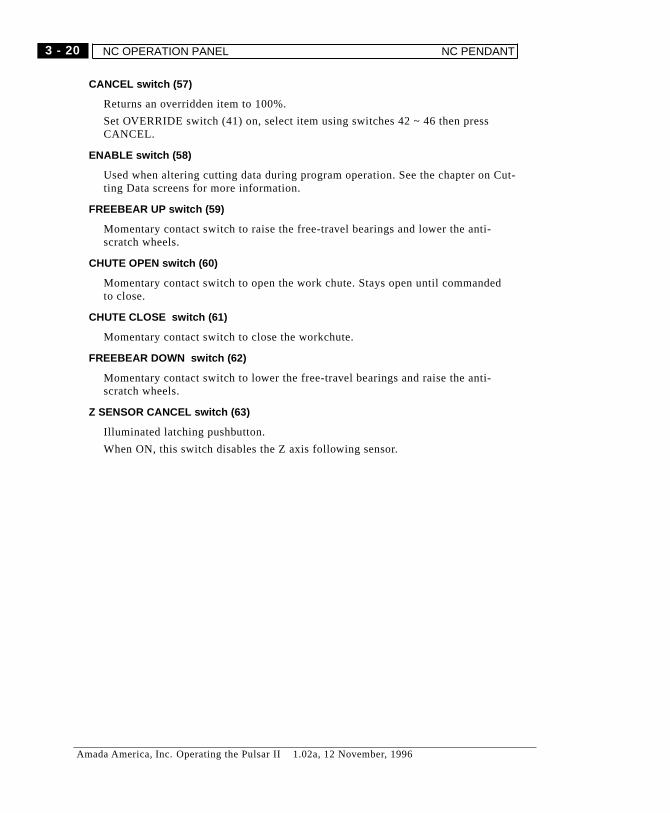
CANCEL switch (57)
Returns an overridden item to 100%.
Set OVERRIDE switch (41) on, select item using switches 42 ~ 46 then pressCANCEL.
ENABLE switch (58)
Used when altering cutting data during program operation. See the chapter on Cut-ting Data screens for more information.
FREEBEAR UP switch (59)
Momentary contact switch to raise the free-travel bearings and lower the anti-scratch wheels.
CHUTE OPEN switch (60)
Momentary contact switch to open the work chute. Stays open until commandedto close.
CHUTE CLOSE switch (61)
Momentary contact switch to close the workchute.
FREEBEAR DOWN switch (62)
Momentary contact switch to lower the free-travel bearings and raise the anti-scratch wheels.
Z SENSOR CANCEL switch (63)
Illuminated latching pushbutton.
When ON, this switch disables the Z axis following sensor.
3 - 20
Amada America, Inc. Operating the Pulsar II 1.02a, 12 November, 1996
NC OPERATION PANEL NC PENDANT
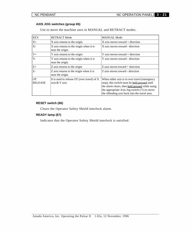
AXIS JOG switches (group 65)
Use to move the machine axes in MANUAL and RETRACT modes.
KEY RETRACT Mode MANUAL Mode
X+ X axis returns to the origin X axis moves toward + direction
X- X axis returns to the origin when it isnear the origin
X axis moves toward - direction
Y+ Y axis returns to the origin Y axis moves toward + direction
Y- Y axis returns to the origin when it isnear the origin
Y axis moves toward - direction
Z+ Z axis returns to the origin Z axis moves toward + direction
Z- Z axis returns to the origin when it isnear the origin
Z axis moves toward - direction
OTRELEASE
It is used to release OT (over travel) of Xaxis & Y axis
When either axis is in over travel (emergencystop), this switch must beheld pressed untilthe alarm clears, thenheld pressed while usingthe appropriate Axis Jog switch (71) to movethe offending axis back into the travel area.
RESET switch (66)
Clears the Operator Safety Shield interlock alarm.
READY lamp (67)
Indicates that the Operator Safety Shield interlock is satisfied.
3 - 21
Amada America, Inc. Operating the Pulsar II 1.02a, 12 November, 1996
NC PENDANT NC OPERATION PANEL
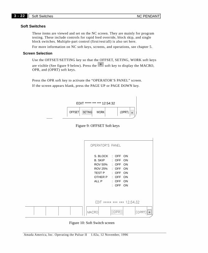
Soft Switches
These items are viewed and set on the NC screen. They are mainly for programtesting. These include controls for rapid feed override, block skip, and singleblock switches. Multiple-part control (first/rest/all) is also set here.
For more information on NC soft keys, screens, and operations, see chapter 5.
Screen Selection
Use the OFFSET/SETTING key so that the OFFSET, SETING, WORK soft keys
are visible (See figure 9 below). Press the soft key to display the MACRO,OPR, and (OPRT) soft keys.
Press the OPR soft key to activate the “OPERATOR’S PANEL” screen.
If the screen appears blank, press the PAGE UP or PAGE DOWN key.
+
OFFSET SETING (OPRT)WORK
EDIT ***** *** *** 12:54:32
+
Figure 9: OFFSET Soft keys
S. BLOCKB. SKIPROV 50%ROV 25%TEST POTHER PALL P
: � OFF ON: � OFF ON: � OFF ON: � OFF ON: � OFF ON: � OFF ON: � OFF ON: � OFF ON
Figure 10: Soft Switch screen
3 - 22
Amada America, Inc. Operating the Pulsar II 1.02a, 12 November, 1996
Soft Switches NC PENDANT
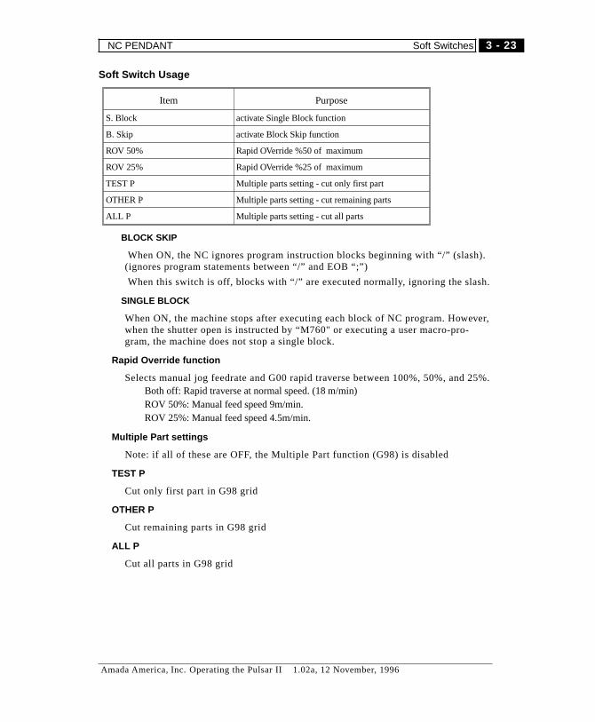
Soft Switch Usage
Item Purpose
S. Block activate Single Block function
B. Skip activate Block Skip function
ROV 50% Rapid OVerride %50 of maximum
ROV 25% Rapid OVerride %25 of maximum
TEST P Multiple parts setting - cut only first part
OTHER P Multiple parts setting - cut remaining parts
ALL P Multiple parts setting - cut all parts
BLOCK SKIP
When ON, the NC ignores program instruction blocks beginning with “/” (slash).(ignores program statements between “/” and EOB “;”)
When this switch is off, blocks with “/” are executed normally, ignoring the slash.
SINGLE BLOCK
When ON, the machine stops after executing each block of NC program. However,when the shutter open is instructed by “M760" or executing a user macro-pro-gram, the machine does not stop a single block.
Rapid Override function
Selects manual jog feedrate and G00 rapid traverse between 100%, 50%, and 25%.Both off: Rapid traverse at normal speed. (18 m/min)ROV 50%: Manual feed speed 9m/min.ROV 25%: Manual feed speed 4.5m/min.
Multiple Part settings
Note: if all of these are OFF, the Multiple Part function (G98) is disabled
TEST P
Cut only first part in G98 grid
OTHER P
Cut remaining parts in G98 grid
ALL P
Cut all parts in G98 grid
3 - 23
Amada America, Inc. Operating the Pulsar II 1.02a, 12 November, 1996
NC PENDANT Soft Switches
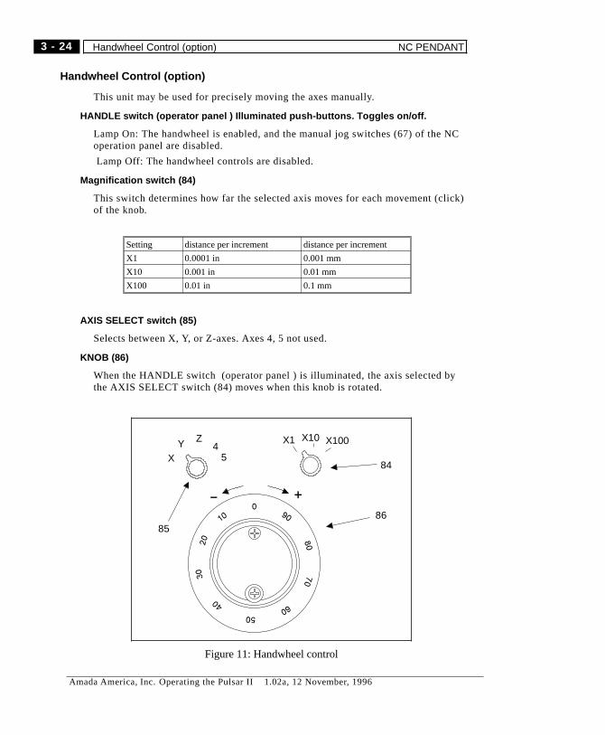
Handwheel Control (option)
This unit may be used for precisely moving the axes manually.
HANDLE switch (operator panel ) Illuminated push-buttons. Toggles on/off.
Lamp On: The handwheel is enabled, and the manual jog switches (67) of the NCoperation panel are disabled.
Lamp Off: The handwheel controls are disabled.
Magnification switch (84)
This switch determines how far the selected axis moves for each movement (click)of the knob.
Setting distance per increment distance per increment
X1 0.0001 in 0.001 mm
X10 0.001 in 0.01 mm
X100 0.01 in 0.1 mm
AXIS SELECT switch (85)
Selects between X, Y, or Z-axes. Axes 4, 5 not used.
KNOB (86)
When the HANDLE switch (operator panel ) is illuminated, the axis selected bythe AXIS SELECT switch (84) moves when this knob is rotated.
X1 X10 X100
XY Z
45
84
8586
Figure 11: Handwheel control
3 - 24
Amada America, Inc. Operating the Pulsar II 1.02a, 12 November, 1996
Handwheel Control (option) NC PENDANT
MACHINE
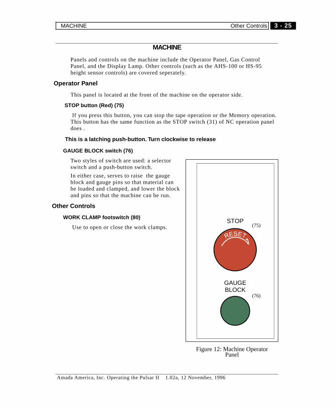
Panels and controls on the machine include the Operator Panel, Gas ControlPanel, and the Display Lamp. Other controls (such as the AHS-100 or HS-95height sensor controls) are covered seperately.
Operator Panel
This panel is located at the front of the machine on the operator side.
STOP button (Red) (75)
If you press this button, you can stop the tape operation or the Memory operation.This button has the same function as the STOP switch (31) of NC operation paneldoes .
� This is a latching push-button. Turn clockwise to release
GAUGE BLOCK switch (76)
Two styles of switch are used: a selectorswitch and a push-button switch.
In either case, serves to raise the gaugeblock and gauge pins so that material canbe loaded and clamped, and lower the blockand pins so that the machine can be run.
Other Controls
WORK CLAMP footswitch (80)
Use to open or close the work clamps.STOP
GAUGEBLOCK
(75)
(76)
Figure 12: Machine OperatorPanel
3 - 25
Amada America, Inc. Operating the Pulsar II 1.02a, 12 November, 1996
MACHINE Other Controls
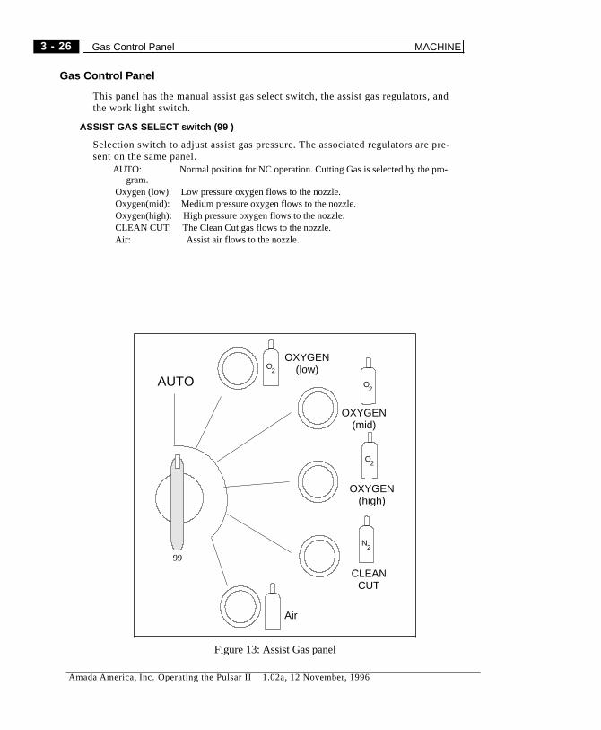
Gas Control Panel
This panel has the manual assist gas select switch, the assist gas regulators, andthe work light switch.
ASSIST GAS SELECT switch (99 )
Selection switch to adjust assist gas pressure. The associated regulators are pre-sent on the same panel.
AUTO: Normal position for NC operation. Cutting Gas is selected by the pro-gram.
Oxygen (low): Low pressure oxygen flows to the nozzle.Oxygen(mid): Medium pressure oxygen flows to the nozzle.Oxygen(high): High pressure oxygen flows to the nozzle.CLEAN CUT: The Clean Cut gas flows to the nozzle.Air: Assist air flows to the nozzle.
AUTOO
2
O2
O2
N2
OXYGEN(high)
CLEANCUT
Air
OXYGEN(mid)
OXYGEN(low)
99
Figure 13: Assist Gas panel
3 - 26
Amada America, Inc. Operating the Pulsar II 1.02a, 12 November, 1996
Gas Control Panel MACHINE
� Caution
Set the selector switch to AUTO for normal operation. In any other position, themanually-selected gas will flow rather than the gas selected by the program or ma-terial cutting data.
Gases are selected according to the Cutting Database, and selected in the part-pro-gram by M120(material name) and E1~E10.
In the cutting data table, the gases are designated as 1..5.
Cutting Gas name (pressure range) Gas kind
Oxygen (low) (gas kind = 1)
Oxygen (middle) (gas kind = 2)
Oxygen (high) (gas kind = 3)
Nitrogen (gas kind = 4)
Air (gas kind = 5)
Assist Gas Pressure Regulators
Select the gas you want to adjust with ASSIST GAS SELECT (99) and adjustwith associated regulator. Pull the handle and turn it to the pressure you want. Af-ter adjusting, push the handle to lock it.
WORK LIGHT switch
Turns the work light on/off. This light is located under the Y-axis carriage area,and serves to illuminate the work surface in the cutting area.
3 - 27
Amada America, Inc. Operating the Pulsar II 1.02a, 12 November, 1996
MACHINE Gas Control Panel

Notes
3 - 28
Amada America, Inc. Operating the Pulsar II 1.02a, 12 November, 1996
Gas Control Panel MACHINE

Chapter 4
Machine Operation
Amada America, Inc. Operating the Pulsar II 1.02a, 12 November, 1996

Notes
4 - 2
Amada America, Inc. Operating the Pulsar II 1.02a, 12 November, 1996
OVERVIEW
This chapter covers machine startup and shutdown, loading and running programs,and general machine operation.
Please read this chapter carefully before operating the machine.
NOTE on internal Floppy Drive:
Sometimes the system may not recognize floppies in MS-DOS format. When pow-ering the control, always have a formatted DOS floppy in place.
Also, when changing floppies, the system must read the disk directory before youcan access it. After closing the access door, either (a) observe through the accessdoor that the indicating LED is ON, or (b) wait at least 10 seconds, before tryingto access the floppy.
MACHINE STARTUP
Main Power
Turn the NC breaker ON
Laser Chiller
Turn the laser chiller ON. (at disconnect, if necessary, and at chiller’s controlpanel)
Confirm that the green light on the chiller is on.
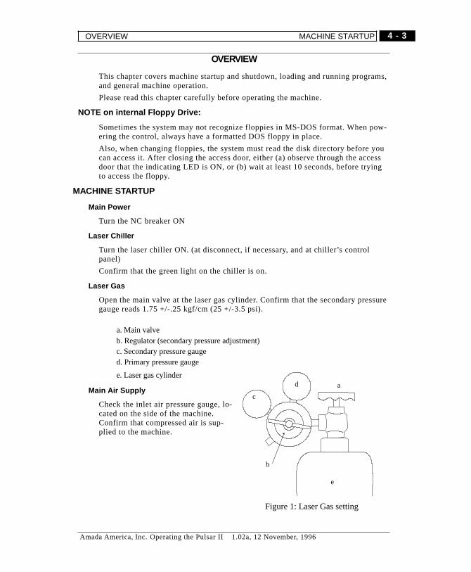
Laser Gas
Open the main valve at the laser gas cylinder. Confirm that the secondary pressuregauge reads 1.75 +/-.25 kgf/cm (25 +/-3.5 psi).
a. Main valveb. Regulator (secondary pressure adjustment)c. Secondary pressure gauged. Primary pressure gauge
e. Laser gas cylinder
Main Air Supply
Check the inlet air pressure gauge, lo-cated on the side of the machine.Confirm that compressed air is sup-plied to the machine.
a
e
c
b
d
Figure 1: Laser Gas setting
4 - 3
Amada America, Inc. Operating the Pulsar II 1.02a, 12 November, 1996
OVERVIEW MACHINE STARTUP
Laser Enable
Confirm that the LASER key switch (32) on the NC operation panel is turned OFF
Machine Power
Turn NFB1 ON (on NC cabinet)
NC Power
Press the ON switch (4) of the CRT/MDI console for a few seconds. The NC willthen power-up.
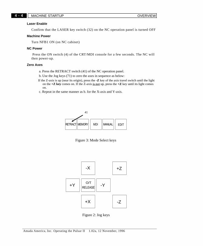
Zero Axes
a. Press the RETRACT switch (41) of the NC operation panel.b. Use the Jog keys (71) to zero the axes in sequence as below:If the Z-axis is up (near its origin), press the-Z key of the axis travel switch until the light
on the+Z key comes on. If the Z-axisis not up, press the+Z key until its light comeson.
c. Repeat in the same manner as b. for the X-axis and Y-axis.
O/T
RELEASE
-X
+X
-Y+Y
-Z
+Z
Figure 2: Jog keys
41
Figure 3: Mode Select keys
4 - 4
Amada America, Inc. Operating the Pulsar II 1.02a, 12 November, 1996
MACHINE STARTUP OVERVIEW
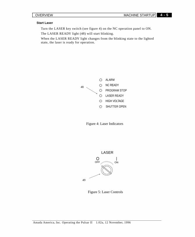
Start Laser
Turn the LASER key switch (see figure 4) on the NC operation panel to ON.
The LASER READY light (48) will start blinking.
When the LASER READY light changes from the blinking state to the lightedstate, the laser is ready for operation.
ALARM
NC READY
PROGRAM STOP
LASER READY
HIGH VOLTAGE
SHUTTER OPEN
48
Figure 4: Laser Indicators
LASER
ONOFF
49
Figure 5: Laser Controls
4 - 5
Amada America, Inc. Operating the Pulsar II 1.02a, 12 November, 1996
OVERVIEW MACHINE STARTUP

Prepare Cutting Head
Remove the cutting head, and make sure the focus lens is clean. If you use morethan one focal length lens make sure you have the correct type installed. Makesure the nozzle and lower head is clean and in good condition. Re-mount the cut-ting head.
See page 10 for details.
Adjusting/Confirming lens focus
Systems WITHOUT NC Focus:The lens focus can be adjusted by turning the lens dial on the laser head. (For sys-tems with motorized focus adjust, use the +B, -B switches (73) on the NC Opera-tor Panel).The desired focal point varies according to the type and thickness of material to becut.Adjust the lens focal point as needed. Actual dial readings will depend on the lensinstalled and individual machine setup variations.
Systems with NC Focus:This system should not need manual adjustments. See the provided documentationon NC Focus.
Nozzle Alignment
Check/adjust nozzle alignment as needed. (see “Nozzle Centering”, beginningpage 8-18)
Set the assist gas pressure.
(for systems without Programmable Assist Gas option)1. Turn the assist gas select switch (on the column control panel) to the desiredgas. The selected gas will be discharged out of the cutting nozzle.2. Check pressure at the assist gas pressure gauge, adjust the regulator knob forthe selected gas as needed.4. Suitable pressure may vary according to the type of operations ( i.e.: piercing,cutting, or scribing) to be done, even if the same material or the same worksheet isbeing used. Set up gas pressures accordingly.5. After setting assist gas pressure(s), turn the assist gas pressure switch to AUTO.
4 - 6
Amada America, Inc. Operating the Pulsar II 1.02a, 12 November, 1996
MACHINE STARTUP OVERVIEW

Calibrate the sensor.
Only when using the optional Capacitive Sensor Head. Program 9000 is used forsensor calibration.
� NOTEThis applies to systems with the AHS-100 Capacitive Sensor system ONLY. For
systems with the HS-95 High-Speed Capacitive Sensor system, see theprovided manual, or contact AMADA for information.
Place a sample of the material to be cut under the head.
Follow the procedures beginning on page 6-4 to select the program.
Select MEMORY mode
Press the CALIBRATE switch on the AHS controller.
Press START to run program 9000.
If no alarms have occurred when the program ends, then the sensor is calibrated.
Set Nozzle Standoff
Only when using the ball transfer head. Use the adjusting wheel to set the dis-tance from tip of nozzle to bottom of transfer balls. (See page 9 in this chapter)
Confirm Program Readiness
If the PROGRAM display is not active, press the FUNC and PROG keys on theCRT/MDI operation panel.
Verify that the cursor is at the beginning of the program (just below the program#) on the CRT screen.
Check Laser
Set the SHUTTER ENABLE key switch (50) on the NC operation panel to ON.
Confirm the pulse set up and condition.
4 - 7
Amada America, Inc. Operating the Pulsar II 1.02a, 12 November, 1996
OVERVIEW MACHINE STARTUP
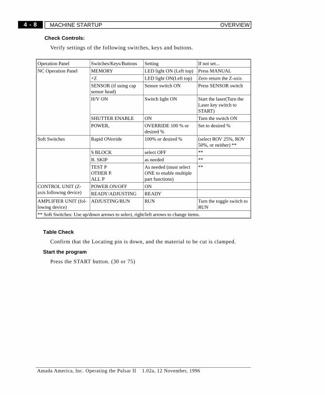
Check Controls:
Verify settings of the following switches, keys and buttons.
Operation Panel Switches/Keys/Buttons Setting If not set...
NC Operation Panel MEMORY LED light ON (Left top) Press MANUAL
+Z LED light ON(Left top) Zero return the Z-axis
SENSOR (if using capsensor head)
Sensor switch ON Press SENSOR switch
H/V ON Switch light ON Start the laser(Turn theLaser key switch toSTART)
SHUTTER ENABLE ON Turn the switch ON
POWER, OVERRIDE 100 % ordesired %
Set to desired %
Soft Switches Rapid OVerride 100% or desired % (select ROV 25%, ROV50%, or neither) **
S BLOCK select OFF **
B. SKIP as needed **
TEST POTHER P.ALL P
As needed (must selectONE to enable multiplepart functions)
**
CONTROL UNIT (Z-axis following device)
POWER ON/OFF ON
READY/ADJUSTING READY
AMPLIFIER UNIT (fol-lowing device)
ADJUSTING/RUN RUN Turn the toggle switch toRUN
** Soft Switches: Use up/down arrows to select, right/left arrows to change items.
Table Check
Confirm that the Locating pin is down, and the material to be cut is clamped.
Start the program
Press the START button. (30 or 75)
4 - 8
Amada America, Inc. Operating the Pulsar II 1.02a, 12 November, 1996
MACHINE STARTUP OVERVIEW
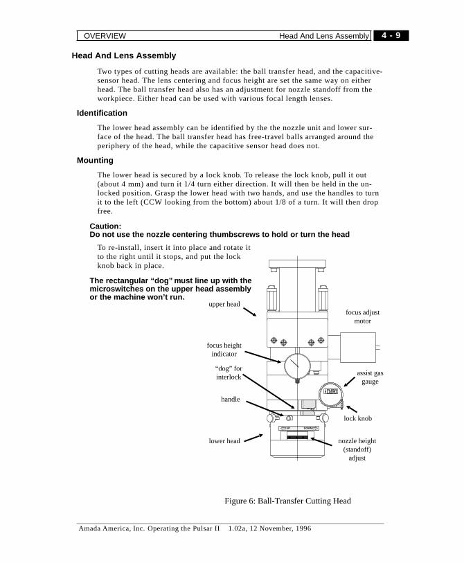
Head And Lens Assembly
Two types of cutting heads are available: the ball transfer head, and the capacitive-sensor head. The lens centering and focus height are set the same way on eitherhead. The ball transfer head also has an adjustment for nozzle standoff from theworkpiece. Either head can be used with various focal length lenses.
Identification
The lower head assembly can be identified by the the nozzle unit and lower sur-face of the head. The ball transfer head has free-travel balls arranged around theperiphery of the head, while the capacitive sensor head does not.
Mounting
The lower head is secured by a lock knob. To release the lock knob, pull it out(about 4 mm) and turn it 1/4 turn either direction. It will then be held in the un-locked position. Grasp the lower head with two hands, and use the handles to turnit to the left (CCW looking from the bottom) about 1/8 of a turn. It will then dropfree.
� Caution:Do not use the nozzle centering thumbscrews to hold or turn the head
To re-install, insert it into place and rotate itto the right until it stops, and put the lockknob back in place.
� The rectangular “dog” must line up with themicroswitches on the upper head assemblyor the machine won’t run.
UP DOWN
nozzle height(standoff)
adjust
upper headfocus adjust
motor
assist gasgauge
handle
lower head
lock knob
focus heightindicator
“dog” forinterlock
Figure 6: Ball-Transfer Cutting Head
4 - 9
Amada America, Inc. Operating the Pulsar II 1.02a, 12 November, 1996
OVERVIEW Head And Lens Assembly
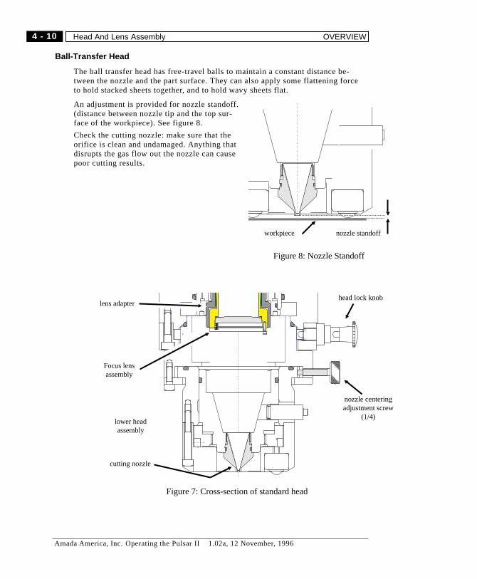
Ball-Transfer Head
The ball transfer head has free-travel balls to maintain a constant distance be-tween the nozzle and the part surface. They can also apply some flattening forceto hold stacked sheets together, and to hold wavy sheets flat.
An adjustment is provided for nozzle standoff.(distance between nozzle tip and the top sur-face of the workpiece). See figure 8.
Check the cutting nozzle: make sure that theorifice is clean and undamaged. Anything thatdisrupts the gas flow out the nozzle can causepoor cutting results.
Focus lensassembly
lens adapter
lower headassembly
cutting nozzle
head lock knob
nozzle centeringadjustment screw
(1/4)
Figure 7: Cross-section of standard head
workpiece nozzle standoff
Figure 8: Nozzle Standoff
4 - 10
Amada America, Inc. Operating the Pulsar II 1.02a, 12 November, 1996
Head And Lens Assembly OVERVIEW
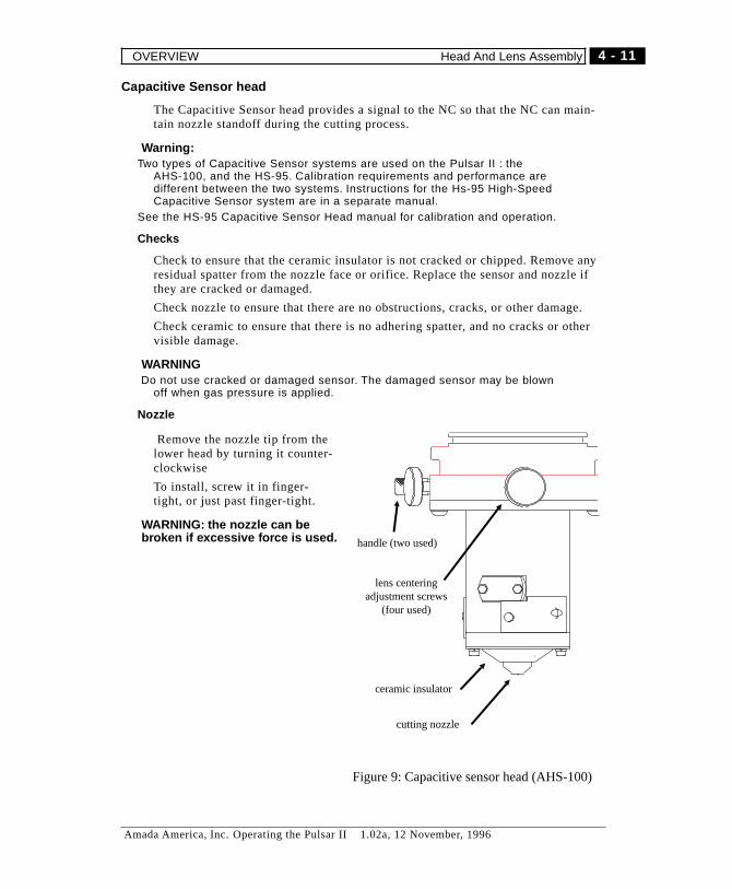
Capacitive Sensor head
The Capacitive Sensor head provides a signal to the NC so that the NC can main-tain nozzle standoff during the cutting process.
� Warning:Two types of Capacitive Sensor systems are used on the Pulsar II : the
AHS-100, and the HS-95. Calibration requirements and performance aredifferent between the two systems. Instructions for the Hs-95 High-SpeedCapacitive Sensor system are in a separate manual.
See the HS-95 Capacitive Sensor Head manual for calibration and operation.
Checks
Check to ensure that the ceramic insulator is not cracked or chipped. Remove anyresidual spatter from the nozzle face or orifice. Replace the sensor and nozzle ifthey are cracked or damaged.
Check nozzle to ensure that there are no obstructions, cracks, or other damage.
Check ceramic to ensure that there is no adhering spatter, and no cracks or othervisible damage.
� WARNINGDo not use cracked or damaged sensor. The damaged sensor may be blown
off when gas pressure is applied.
Nozzle
Remove the nozzle tip from thelower head by turning it counter-clockwise
To install, screw it in finger-tight, or just past finger-tight.
� WARNING: the nozzle can bebroken if excessive force is used. handle (two used)
cutting nozzle
ceramic insulator
lens centeringadjustment screws
(four used)
Figure 9: Capacitive sensor head (AHS-100)
4 - 11
Amada America, Inc. Operating the Pulsar II 1.02a, 12 November, 1996
OVERVIEW Head And Lens Assembly

Focus Lens
The machine can use any one of several focus lens assemblies. Each type of lens(5", 3.75", 2.5") needs to be used with the corresponding adapter.
� Warning
If the lens and adapter are not the same type, the focused spot will be far aboveor below the proper part of the head, and will not clear the nozzle opening.
Damage may occur to the lens, nozzle, or other machine components.
The lens adapter can be identified by its length. and the type of lens can be identi-fied by the number on the lens mount. Normally, a 5" lens is used. The lenses andapproximate adapter lengths are described below.
LENS ADAPTER LENGTH
5 1.4"
3.75 2.65"
2.5 3.9"
Lens Removal
Only about 4-5 mm of the lens assembly protrude from the lens adapter. The lensadapter is knurled on the gripping surface, while the lens mount is smooth, withscrew heads protruding from the lower surface. Grip the lens mount and unscrewit (counter-clockwise) to remove it. Avoid touching the surface of the lens withanything, except when actually cleaning it using approved materials and tech-niques.
Lens Cleaning
Clean the lens by wiping each surface with a cotton swab saturated with acetone.
DO NOT APPLY PRESSURE while wiping - this can damage the coating and re-duce the life of the lens. Lens tissue may be folded and used instead of cotton, ifdesired.
Lens Installation
When installing a lens assembly, screw it into the adapter finger-tight. Be carefulnot to touch the surface of the lens while tightening it.
Adapter removal/installation
The adapter has an O-ring which can make it quite difficult to remove. Removethe lens assembly first to avoid damage to it. Grasp the knurled portion of theadapter and unscrew it (counter-clockwise). When installing an adapter, makesure to turn it in until it seats.
4 - 12
Amada America, Inc. Operating the Pulsar II 1.02a, 12 November, 1996
Head And Lens Assembly OVERVIEW

AUTOMATIC OPERATION
Automatic Operation modes include “MDI Operation” and “Automatic Operation”.
Press the MEMORY (44) or MDI (43) key on the Operation panel. (MODEswitches)
MEMORY mode operation
Use MEMORY mode to execute stored program(s) to operate the machine.
1) Load the program into the NC memory, if it isn’t already present.(Refer to page 6-4. in this manual)
2) Modify the program, if necessary.(Use EDIT mode for modifying program)
3) Press the MEMORY(44) key on the Fanuc keypanel.
4) Select the program, if it is not already active, and make sure the cursor (startpoint) is at the beginning of the program.
5) Press START to begin operation.
MDI mode operation
MDI operation is a way to create and run a “one-shot’ program. It must be keyedin using the MDI/CRT operation panel, and is temporarily stored into the MDI op-eration buffer. MDI may be used for various test and adjustment operations.
1) Press the MDI (43) key of the Operation Mode Selection Switch.
2) Store (temporary) program into the MDI operation buffer by keyboard input.
3) Operation will start when the START switch is pressed.
Starting Automatic Operation
Normally, the cursor should be at the beginning of the program before starting.
To start operation, select MEMORY mode or MDI mode and press the STARTswitch (30 or 75).
The START light (30) will turn on while the program is running.
4 - 13
Amada America, Inc. Operating the Pulsar II 1.02a, 12 November, 1996
AUTOMATIC OPERATION Starting Automatic Operation

Program Execution
In Automatic operation, the NC:
1. Starts reading the first block of commands of the selected program .
2. Interprets the first block of commands.
3. Executes the commands.
4. Starts reading the next block of commands.
5. Interprets the next block of commands and prepares for the next execution.This process is called buffering.
6. Upon execution of a block of commands, immediately starts executing the nextblock of commands because the succeeding block of commands has been readwhile executing the preceding block of commands.
7. Repeats the process of 4-5-6 while in automatic operation.
Stopping automatic operation
The automatic operation can be stopped by the program which contains the StopCommand (M00). The automatic operation can be also stopped by pressingswitches on the operation panel. Also, the operation will stop when emergency oralarm occurs.
Program stop (M00)
The automatic operation will stop any time the block of command which contains“M00" is executed. The modal codes for the operation are saved when the opera-tion is stopped by the program stop command, and therefore, a stopped operationcan be resumed when START switch is pressed. This is similar to the STOP byuse of Single Blocking. The START light will stay on while the program is beingstopped by M00.
Program end (G50, M30, M02)
M30 and M02 are the codes which indicate the end of the main program. The ma-chine will not allow the transfer of a program into NC memory (except bykeyboard) without these codes.
When these commands are executed, the machine will end automatic operationand reset all modal codes, and return to the beginning of the program.
4 - 14
Amada America, Inc. Operating the Pulsar II 1.02a, 12 November, 1996
Program Execution AUTOMATIC OPERATION

To STOP Operation
Program execution may be stopped in several ways, depending on the need. TheSTOP switch may be used, as can the RESET and EMERGENCY STOP switches.
Emergency Stop
The machine will immediately stop operation when the EMERGENCY STOPswitch on the NC operation panel is pressed. The machine will do the followingwhen the EMERGENCY STOP switch is pressed:
-Stop all axes
-Stop power discharge of the laser
-Close the shutter
-Turn off the assist gas
To restart the operation,
1) Remove the cause of the stop
2) Unlock the pressed EMERGENCY STOP switch by turning it clockwise
3) Press RESET key
4) Zero-return all axes to their origins
5) Press H/V ON on the NC Operator panel.
RESET
Pressing RESET key releases the current state and operation of the machine andresets the machine. For example, the RESET key is used to stop an alarm duringautomatic operation or to stop automatic operation.
It can be also used to move (the cursor) to the beginning of a program while edit-ing program.
When the RESET key is pressed, the machine will do the following:
-Stop all axes
-Close the shutter
-Turn off assist gas
To restart the operation
1) Remove the cause to stop
2) Zero-return the Z-axis
3) Return to the beginning of the program
The machine will do the following when the RESET key is pressed when theswitch of the operation mode is set to Edit mode:
-Return the cursor to the beginning of program
-Clears the contents of the buffer by keyboard input.
4 - 15
Amada America, Inc. Operating the Pulsar II 1.02a, 12 November, 1996
AUTOMATIC OPERATION Program Execution
STOP (Temporary)
Operation can be interrupted by pressing the STOP switch is pressed.
� Warning!
Pressing STOP switch while the axes are in motion or when the shutter is openmay cause damages to the machine. Do not press STOP switch while the axes aremoving or when the shutter is open.
When the STOP switch is pressed during automatic operation, the STOP switchlight will turn on and the machine will do the following:
-Stop all axes
-Close the shutter
-Turn off assist gas
The interrupted operation can be resumed by,1) Removing the cause of the interruption2) Pressing down he START switch for about a second if you want to continue op-eration
Press the RESET key if you don’t want to continue operationRefer to the RESET procedure above (see page 4-15 )
� Warning!The machine will stop at its current state/position when the STOP switch ispressed.Therefore, turn the STOP switch of the table control panel to clockwise and pressagain the STOP switch of the NC operation panel.
Machine Halts (Automatic)
Various machine conditions will cause operation to stop. Depending on specifics,you may or may not be able to continue operation.
Dead Zone (without escaping clamp option)
If the laser head moves into a dead zone and the alarm occurs, you must restartthe operation:
1) Press the MANUAL switch (42)2) Raise the Z-axis slightly3) Press RESET key and release the alarm4) Press +Y switch to move the Y-axis out of the dead zone5) Press the Zero - return switch (41)6) Zero - return the Z-axis, then the X and Y-axes.
4 - 16
Amada America, Inc. Operating the Pulsar II 1.02a, 12 November, 1996
Program Execution AUTOMATIC OPERATION

Overtravels (soft)
When the axes move beyond the stroke area , the “Overtravel” NC alarm occursand operation stops.
To restart the operation:1) Press MANUAL key of the operational mode select switch2) Press the switch that has opposite direction to the over travel signal (e.g., whenthe over travel is -Z, press +Z) in order to move the axis back to the stroke area.
Alarm Sign Switch to select
Over travel +Z -Z
Over travel -Z +Z
3) Press RESET key to release the alarm.4) Press Zero-return key (41) of the operational mode select key5) Zero-return the Z-axis.
Overtravels (emergency stop)
When an axis moves beyond the (soft) overtravel zone and activates an EmergencyStop Over Travel limit switch, NOT READY will be displayed at the left bottomcorner of the screen and axis motion stops.
To restart the operation1) Press the MANUAL (42) mode select switch2) Press down the OT RELEASE SWITCH (69) for a few seconds, the alarmlamp (46) (red) and the NOT READY display of the CRT display will go off.3) Keep pressing down the OT RELEASE SWITCH (69) while using the neces-sary AXIS JOG Pbs to move the axes back to the normal travel area.4) Press RESET key to release the alarm.5) Press the RETRACT key (41) of the operational mode select switch.6) Retract the Z-axis.7) Retract the X-axis and Y-axis.
� Warning:The laser discharge (High Voltage) will be turned off when the operation isstopped by an emergency. Do the following :
8) Press H/V ON on the NC Operator panel.
4 - 17
Amada America, Inc. Operating the Pulsar II 1.02a, 12 November, 1996
AUTOMATIC OPERATION Program Execution

Manual Feed & Manual Handle Feed
The axes can be moved manually by using the Jog switches or the manual hand-wheel (option).
Manual Jog
Press the MANUAL key (42)Select the jog feedrate by selecting one of the switches ( group 72) to 25%, 50%,or 100%.( The speed of the X-axis and Y-axis are 20m/min. when set to 100%)Press the axis travel switch of the axis you want to move. (group 71)
Handle Feed
Press the REMOTE CONTROL ON/OFF button (84) on the remote control panel.Select an axis you want to move from axis select handle (86).Manual Feed can be performed by turning the knob (88).Set “per scale” travel by knob (85).Turn the manual handle (87) to move the selected axis.
4 - 18
Amada America, Inc. Operating the Pulsar II 1.02a, 12 November, 1996
Program Execution AUTOMATIC OPERATION
TEST OPERATION
Program Check
Check to confirm that the correct programs are registered in the memory and inthe new NC program tape before execution.
Execute the commands of programs in only NC without using the laser emission.
Procedure:1) Turn the laser key switch (32) on the NC operation panel to START or STOP.2) Select HeNe of the laser select key switch (50).3) Run the machine just as in normal automatic operation. (Cutting speed shouldbe set to the axis jog travel speed)
Testing Operation is recommended for the following situations:
Any program which has been edited since prior test.
Programs made by digitizer.
Testing for “laser beam path compensation overcut” alarm
� Warning:
Always Retract the all axes after test operation.
Retract the axes even when test operation is canceled in the middle to start actualoperation.
Confirm that there are no obstacles and persons around the machine because thetable (axes) will start moving.
4 - 19
Amada America, Inc. Operating the Pulsar II 1.02a, 12 November, 1996
AUTOMATIC OPERATION TEST OPERATION
STOPPING OPERATION
When it is necessary to stop operation, you can stop the operation in the followingtwo manners:
Stop (Reset) Operation
Press RESET key to stop operation. Note that when the operation is stopped by us-ing the RESET key, pressing START switch will not restart the operation.
1) When multiple cut program is being used,Press RESET key and the START switch first, it will Zero-return the all axes. Af-ter removing the cause of the stop, modify the operation start point of the multiplecut program and restart the operation.
2) When multiple cut program is not being used,Remove the cause of the stop after pressing RESET key, and Zero-return the Z-axis. Move to the operation start point by using Manual Feed or MDI operationand then restart the operation.
� Warning
Confirm that the cursor is returned to the beginning of the program before youstart the next operation.
Stop Operation (Temporary)
Press STOP switch if you want to interrupt operation.
� Warning:
The STOP switch is not effective when the machine is actually cutting . Press theRESET key to stop operation while it is actually cutting .
The operation can be interrupted when the laser beam is OFF. If STOP is pressedin this conditions, press START switch to continue the operation.
If the machine (or part) can’t be continued, press the RESET key to stop operation.
4 - 20
Amada America, Inc. Operating the Pulsar II 1.02a, 12 November, 1996
STOPPING OPERATION AUTOMATIC OPERATION
SHUTDOWN PROCEDURE
Laser Shutdown
Turn the Laser switch (32) to STOP. This will begin the automatic Laser Shut-down Procedure.
Machine Shutdown
1) Zero-return all the axes to their origins.2) Remove the lens and the laser head.Inspect the removed lens, clean it if necessary, and store it in the case.3) Inspect the nozzle unit, clean it if necessary. Replace it by turning it clockwise,and push in the lock bar.4) When the laser has finished shutting down, press the POWER OFF switch onthe NC operation panel.
Note:The POWER OFF switch is IGNORED until the Laser Shutdown Procedure is
complete.
5) Turn off the NC operation panel circuit breaker (1) located on the side of theNC operation panel.6) Turn off the laser circuit breaker.7) Close the assist gas (O2, N2, etc.) valves.8) Turn off the NC auto breaker and the laser auto breaker switch. Do not turn offthe chiller auto breaker switch.9) Close the laser gas cylinder valve and the main valve.
See page 3 for illustration.
4 - 21
Amada America, Inc. Operating the Pulsar II 1.02a, 12 November, 1996
SHUTDOWN PROCEDURE STOPPING OPERATION

NOTES
4 - 22
Amada America, Inc. Operating the Pulsar II 1.02a, 12 November, 1996
STOPPING OPERATION SHUTDOWN PROCEDURE

Chapter 5
NC Operations
Amada America, Inc. Operating the Pulsar II 1.02a, 12 November, 1996

Notes
5 - 2
Amada America, Inc. Operating the Pulsar II 1.02a, 12 November, 1996
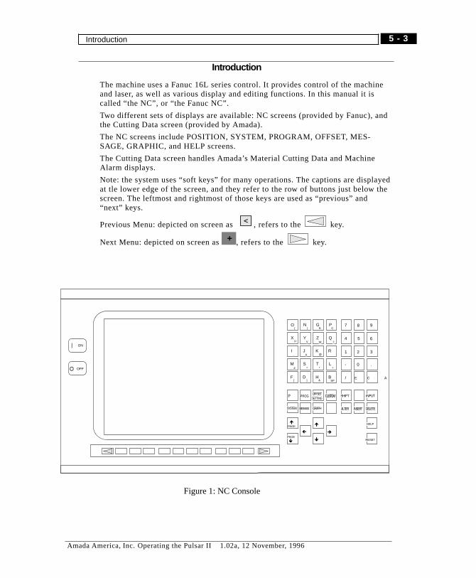
Introduction
The machine uses a Fanuc 16L series control. It provides control of the machineand laser, as well as various display and editing functions. In this manual it iscalled “the NC”, or “the Fanuc NC”.
Two different sets of displays are available: NC screens (provided by Fanuc), andthe Cutting Data screen (provided by Amada).
The NC screens include POSITION, SYSTEM, PROGRAM, OFFSET, MES-SAGE, GRAPHIC, and HELP screens.
The Cutting Data screen handles Amada’s Material Cutting Data and MachineAlarm displays.
Note: the system uses “soft keys” for many operations. The captions are displayedat tle lower edge of the screen, and they refer to the row of buttons just below thescreen. The leftmost and rightmost of those keys are used as “previous” and“next” keys.
Previous Menu: depicted on screen as , refers to the key.
Next Menu: depicted on screen as , refers to the key.+
O N G P
X Y Z Q
I J K R
M S T L
F D H B
7 8 9
4 5 6
1 2 3
- 0 .
/ E OC A
( ) E C
U V W ?
, A @
# = * +
[ ] & SP
P OPROG
PAGE
INPUTSHIFTCUSTOM
PAGE
SYSTEM GRAPH ALTER INSERT DELETE
HELP
RESET
OFFSETSETTING
MESSAGE
ç è
é
ê
é
ê
ON
OFF
Figure 1: NC Console
5 - 3
Amada America, Inc. Operating the Pulsar II 1.02a, 12 November, 1996
Introduction

OVERVIEW
The “home screen” for the system is a split-screen display, showing system status,machine position, and related information in the main part of the screen. This sec-tion presents an overview of screen selection and layout. The next sectiondescribes operations possible from each screen.
For use of Amada’s Custom/Cutting Data screens see chapter 7.
For program editing procedures, see chapter 6.
Keyboards
As detailed in chapter 3, two styles of keyboards are used on the NC. The functionkeys are depicted in figures 3, 2 below. The remainder of this chapter will assumethat you have the full alphanumeric keyboard. If you have the NC-style keyboard,ignore the references to the FUNC key. See page 3-5 for further information.
Figure 2: Function keys (full k.b.) Figure 3: Function keys (NC-style K.B.)
5 - 4
Amada America, Inc. Operating the Pulsar II 1.02a, 12 November, 1996
OVERVIEW
Screen Selection
Selection of main screens is done using Function keys on the Fanuc keyboard.(see figure 2 below) To select one of the NC screens, press the FUNC key and thefunction key designating the desired screen (POS, SYSTEM, PROG, OFFSET, MES-
SAGE, GRAPH).
Press the “CUSTOM” key to go to the Cutting Data screen from any NC screen.
General purpose/contents of screens:
OFFSET:“Handy” settings, Operator Settings (Soft Switches), Laser Beam Compensation,Work coordinate system, Macro-variables, Laser power (1), Cutting Data (2).
SYSTEM:Parameters, Diagnostics, PMC (3), System composition, Memory content, Pitch er-ror setting, Servo-setting, settings of part count, run time, etc.(4)
MESSAGE:Alarm message, Operator message, Alarm history.
PROGRAM:EDIT mode: Part-program, Program Library, Floppy disk operationsMDI mode: Next block display, MDI program input/execution.
GRAPHIC:Graphic Parameters, Drawing (not used)
HELP:Alarms, Controls, Parameters.
Once a screen is selected, soft keys become available to select other screensand/or perform various functions.
� NOTE
Some screens can only be entered or exited by use of a function key (or FUNC+function key).
5 - 5
Amada America, Inc. Operating the Pulsar II 1.02a, 12 November, 1996
OVERVIEW Screen Selection
1 The Cutting Data screen is preferred for display of this information.2 The Cutting Data screen is preferred for display of this information.3 Authorized service personnel only4 Also available using Position display and soft-key operations (OPRT)
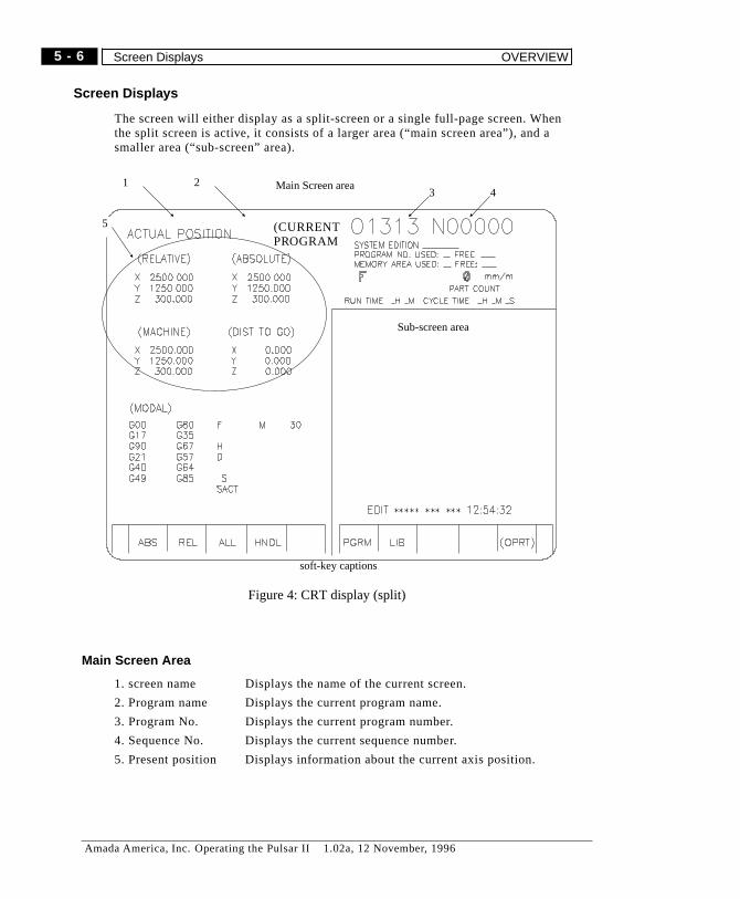
Screen Displays
The screen will either display as a split-screen or a single full-page screen. Whenthe split screen is active, it consists of a larger area (“main screen area”), and asmaller area (“sub-screen” area).
Main Screen Area
1. screen name Displays the name of the current screen.
2. Program name Displays the current program name.
3. Program No. Displays the current program number.
4. Sequence No. Displays the current sequence number.
5. Present position Displays information about the current axis position.
Main Screen area
soft-key captions
Sub-screen area
(CURRENTPROGRAM
32
5
41
Figure 4: CRT display (split)
5 - 6
Amada America, Inc. Operating the Pulsar II 1.02a, 12 November, 1996
Screen Displays OVERVIEW

SCREENS and CONTROLS
Main Screen operation
Press “FUNC” and “POS” keys to select “PRESENT POSITION”. The followingfour screens are available using soft keys:
screen 1: Absolute display
Press the “ABS” soft key to display the present position on the program coordi-nate system set with “G92". The following information is shown:
Present position in Absolute coordinates, Machine coordinatesDistance To Go.Modal status (active G-code modes and M-code modes)Part Count, Run Time, Cycle timeThe soft key assignments are:ABS AbsoluteREL RelativeALL GeneralHNDL Handle(OPRT) more options/ advanced operations
Screen 2: Relative display
Press the “REL” soft key to display the present position in the relative coordinatesystem. This coordinate system is settable by the operator. Refer to page 9 for pre-set procedure.
Present position in Absolute coordinate, Machine coordinates.Distance To GoModal status (active G-code modes and M-code modes)Part Count, Run Time, Cycle timeThe soft key assignments are the same as above.
5 - 7
Amada America, Inc. Operating the Pulsar II 1.02a, 12 November, 1996
SCREENS and CONTROLS Main Screen operation
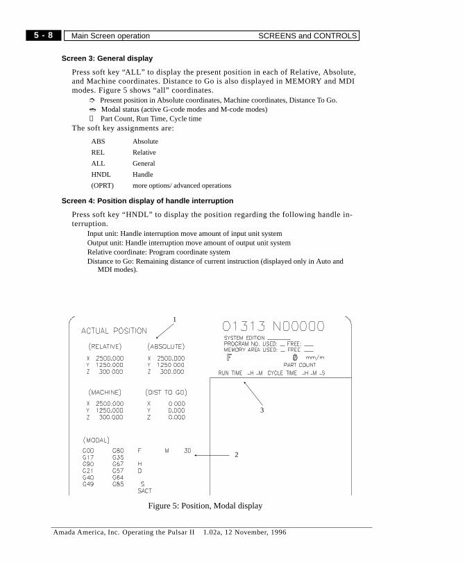
Screen 3: General display
Press soft key “ALL” to display the present position in each of Relative, Absolute,and Machine coordinates. Distance to Go is also displayed in MEMORY and MDImodes. Figure 5 shows “all” coordinates.
➮ Present position in Absolute coordinates, Machine coordinates, Distance To Go.➬ Modal status (active G-code modes and M-code modes)➄ Part Count, Run Time, Cycle time
The soft key assignments are:
ABS Absolute
REL Relative
ALL General
HNDL Handle
(OPRT) more options/ advanced operations
Screen 4: Position display of handle interruption
Press soft key “HNDL” to display the position regarding the following handle in-terruption.
Input unit: Handle interruption move amount of input unit systemOutput unit: Handle interruption move amount of output unit systemRelative coordinate: Program coordinate systemDistance to Go: Remaining distance of current instruction (displayed only in Auto and
MDI modes).
1
2
3
Figure 5: Position, Modal display
5 - 8
Amada America, Inc. Operating the Pulsar II 1.02a, 12 November, 1996
Main Screen operation SCREENS and CONTROLS
POSITION Screen
Use the FUNC + POS keys to select the FULL SCREEN position display.
To exit any of the following operations, use FUNC + (function key) to reselect thepreferred screen.
Parts Count Reset
1) Press soft key “(OPRT)” the soft key display changes.
2) Press soft key “PTSPRE”. “PARTS COUNT” on the screen blinks.
3) Press soft key “EXEC”. “PARTS COUNT” is then reset to “0".
Run time Reset
1) Press soft key “(OPRT)” the soft key display changes.
2) Press soft key “RUNPRE”. “RUN TIME” on the screen blinks.
3) Press soft key “EXEC”. “RUN TIME” is reset to “0".
Relative Coordinate Origin
The relative coordinate system can be zeroed or preset with arbitrary values for X,Y, Z.
Reset to 0:
1) Select “RELATIVE” or “GENERAL” display with soft key (REL or ALL).
2) Press soft key “(OPRT)”, the soft key display changes.
3) Press soft key “ORIGIN”. When you want a specific axis to be “0", key in thename of axis with ‘Address/Numerical value key’ (e.g. ”X"). When you want allaxes to be “0", press soft key ”ALLEXE".
4) Press soft key “EXEC” to reset the coordinate value of the designated axis to“0".
Preset to arbitrary numerical value.
1) Select “(RELATIVE)” display from the “General display” with soft key REL.
2) Press soft key “(OPRT)”, the soft key display changes.
3) Key in the name of axis and the numerical value you want to preset with ‘Ad-dress/Numerical value key’ (e.g. “X100").
In the (RELATIVE) display at the top left of the screen, the selected axis (withcurrent value) blinks.
4) Press soft key “PRESET”. Then the coordinate value of the axis designated ispreset to the numerical value instructed.
5 - 9
Amada America, Inc. Operating the Pulsar II 1.02a, 12 November, 1996
SCREENS and CONTROLS POSITION Screen

SYSTEM Screen
Press “FUNC” and “SYSTEM” keys to select the SYSTEM screen. It is a functionscreen used for maintenance and adjustment. This is a split screen, with the SYS-TEM screen in the small portion.
� Caution:
The SYSTEM function deals with various parameters to operate the machine nor-mally. Normally it is protected. If the contents are changed, the machine may notoperate normally or accurately. Use only if/as instructed by representatives ofAMADA.
Operation of SYSTEM Screen
Press “FUNC” + “SYSTEM” keys to display the SYSTEM screen.
Parameter
Press the “PARAM” soft key to show the parameter screen. Standard parametersare installed by Amada or FANUC.
Diagnostic
Press the “DGNOS” soft key to show the diagnosis screen. It is used to diagnoseeach condition of NC.
PMC
Press the “PMC” soft key to show the PMC screen. Standard parameters are in-stalled by Amada or FANUC.
System composition
Press the “SYSTEM” soft key to show the system screen. Standard parameters areinstalled by Amada or FANUC.
� Note:To show either of the following two screens, select the SYSTEM screen, then use
the soft key (the key) to display the PITCH, SV-PRM captions.
Pitch error setting
From the SYSTEM display, press the “PITCH” soft key to show the pitch error set-ting screen. Standard parameters are installed by Amada or FANUC.
Servo setting
Press soft key “SV-PRM” to show the servo setting and adjustment screen.
+
5 - 10
Amada America, Inc. Operating the Pulsar II 1.02a, 12 November, 1996
SYSTEM Screen SCREENS and CONTROLS

PROGRAM Screens
This section covers the screens available in EDIT mode. Some of these screensand options are not available in other modes. For MDI mode, see page 14.
Press “FUNC” and “PROG” keys to display the PROGRAM screen. The PGM(program), LIB (Library), and MDI screens are available. See figure 6 for thescreen and soft keys sequence.
Available Screens
The Following screens areavailable in EDIT mode:
1. Main screen (split orfull screen) with initialsoft key assignments.
2. Main screen with ex-tended soft keys for ed-iting.
3. Main screen with ex-tended soft keys forprogram handling.
4. Extended soft keys forFloppy disk. (option)
5. Floppy disk directory.(option)
6. File handling withFloppy disk.(option)
Soft key sequences
A number of screens areavailable in the Programgroup of screens. They areaccessed by use of softkeys. The illustration in fig-ure 6 shows therelationships and how toget from one screen to thenext.
1
2
3
4
5
6
EDIT ***** *** *** 12:54:32
PGRM LIB (OPRT) +
SRH REWINDSRH
EDIT ***** *** *** 12:54:32
BG-EDT O SRH +
<
EDIT ***** *** *** 12:54:32
F SRH READ EX-EDTPUNCH DELETE +
EDIT ***** *** *** 12:54:32
+FLOPPY (OPRT)
EDIT ***** *** *** 12:54:32
PRGRM DIR (OPRT)
<
EDIT ***** *** *** 12:54:32
F SRH READ RENAMEPUNCH DELETE
Figure 6: Program screen soft keys
5 - 11
Amada America, Inc. Operating the Pulsar II 1.02a, 12 November, 1996
SCREENS and CONTROLS PROGRAM Screens
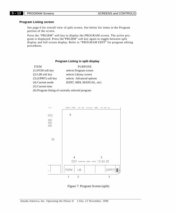
Program Listing screen
See page 6 for overall view of split screen. See below for items in the Programportion of the screen.
Press the “PRGRM” soft key to display the PROGRAM screen. The active pro-gram is displayed. Press the"PRGRM" soft key again to toggle between splitdisplay and full screen display. Refer to “PROGRAM EDIT” for program editingprocedures.
Program Listing in split display
ITEM PURPOSE(1) PGM soft key selects Program screen(2) LIB soft key selects Library screen(3) (OPRT) soft key selects Advanced options(4) Current mode (EDIT, MDI, MANUAL, etc)(5) Current time(6) Program listing of currently selected program
1 2 3
54
6
+
Figure 7: Program Screen (split)
5 - 12
Amada America, Inc. Operating the Pulsar II 1.02a, 12 November, 1996
PROGRAM Screens SCREENS and CONTROLS
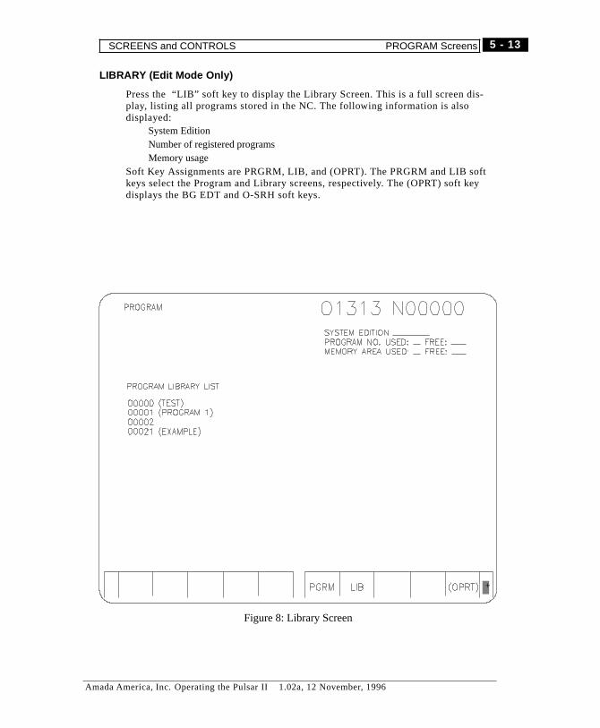
LIBRARY (Edit Mode Only)
Press the “LIB” soft key to display the Library Screen. This is a full screen dis-play, listing all programs stored in the NC. The following information is alsodisplayed:
System EditionNumber of registered programsMemory usage
Soft Key Assignments are PRGRM, LIB, and (OPRT). The PRGRM and LIB softkeys select the Program and Library screens, respectively. The (OPRT) soft keydisplays the BG EDT and O-SRH soft keys.
+
Figure 8: Library Screen
5 - 13
Amada America, Inc. Operating the Pulsar II 1.02a, 12 November, 1996
SCREENS and CONTROLS PROGRAM Screens
FLOPPY
The soft key displays the FLOPPY soft key.
See Chapter 6 page 20 for more information on transferring programs between theNC and floppy disk.
MDI Screen
PROGRAM (MDI) (MDI Mode Only)
Press the “MDI” soft key to show the “Manual Data Input” screen. It can be usedto do various “one-shot” operations. In this mode, you create a program to be runonly once. It may have one or more instructions. This temporary program can notbe saved, and is erased after running. For operations which will be repeated ordone on a regular basis, use a regular program instead.
+
5 - 14
Amada America, Inc. Operating the Pulsar II 1.02a, 12 November, 1996
PROGRAM Screens SCREENS and CONTROLS

OFFSET Screen
The OFFSET screens are used for adjustment/setting of cutter offset and settingdata. Press the “FUNC” and “OFFSET” keys to cycle between the three majorscreens in this group. Other screens may be selected pressing soft keys.
Main CUTTER OFFSET screen
Press the “Offset”soft key to show the laser beam compensation screen. This is afull screen display.
Item Meaning
(1) offset number
(2) distance to offset from programmed path
(3) Key input buffer display
(4) mode and time-of-day
1 2
3 4
1 2
Figure 9: Main Offset screen
5 - 15
Amada America, Inc. Operating the Pulsar II 1.02a, 12 November, 1996
SCREENS and CONTROLS OFFSET Screen
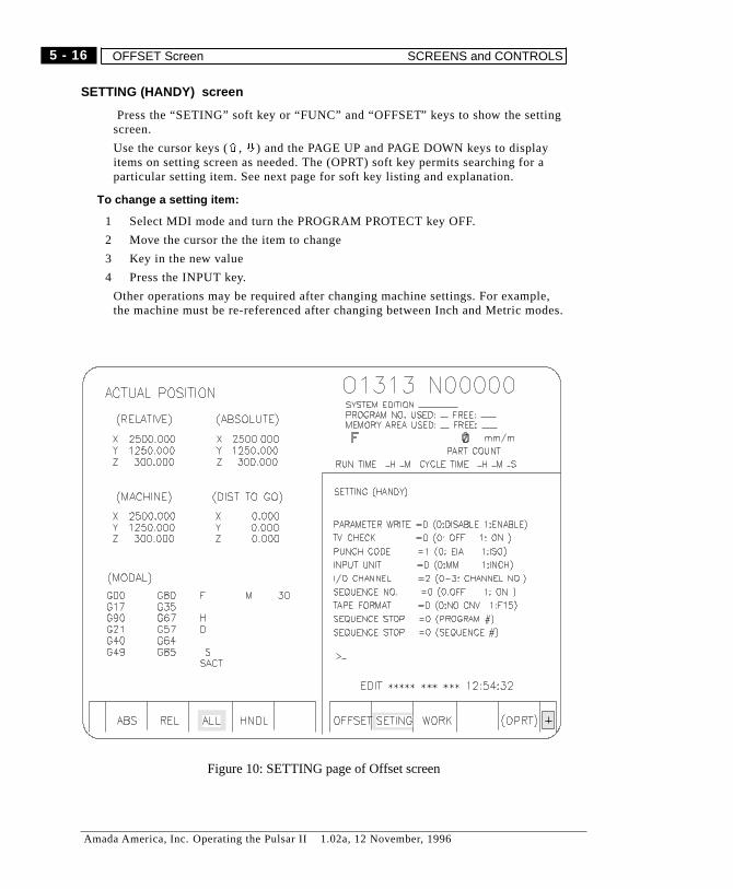
SETTING (HANDY) screen
Press the “SETING” soft key or “FUNC” and “OFFSET” keys to show the settingscreen.
Use the cursor keys (ñ, ò) and the PAGE UP and PAGE DOWN keys to displayitems on setting screen as needed. The (OPRT) soft key permits searching for aparticular setting item. See next page for soft key listing and explanation.
To change a setting item:
1 Select MDI mode and turn the PROGRAM PROTECT key OFF.
2 Move the cursor the the item to change
3 Key in the new value
4 Press the INPUT key.
Other operations may be required after changing machine settings. For example,the machine must be re-referenced after changing between Inch and Metric modes.
Figure 10: SETTING page of Offset screen
5 - 16
Amada America, Inc. Operating the Pulsar II 1.02a, 12 November, 1996
OFFSET Screen SCREENS and CONTROLS
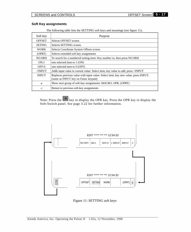
Soft Key assignments
The following table lists the SETTING soft keys and meanings (see figure 11).
Soft key Purpose
OFFSET Selects OFFSET screen
SETING Selects SETTING screen.
WORK Selects Coordinate System Offsets screen.
(OPRT) Selects extended soft key assignments
NO.SRH To search for a numbered setting item: Key number in, then press NO.SRH
ON:1 sets selected item to 1 (ON)
OFF:0 sets selected item to 0 (OFF)
+INPUT Adds input value to current value: Select item, key value to add, press +INPUT
INPUT Replaces previous value with input value: Select item, key new value, press INPUT.(same as INPUT key on Fanuc keypad)
+ Show next group of soft-key assignments: MACRO, OPR, (OPRT)
< Return to previous soft-key assignments
Note: Press the key to display the OPR key. Press the OPR key to display theSoft-Switch panel. See page 3-22 for further information.
+
EDIT ***** *** *** 12:54:32
+NO.SRH ON:1 OFF:0 INPUT+ INPUT
OFFSET SETING (OPRT)WORK
EDIT ***** *** *** 12:54:32
+<
Figure 11: SETTING soft keys
5 - 17
Amada America, Inc. Operating the Pulsar II 1.02a, 12 November, 1996
SCREENS and CONTROLS OFFSET Screen
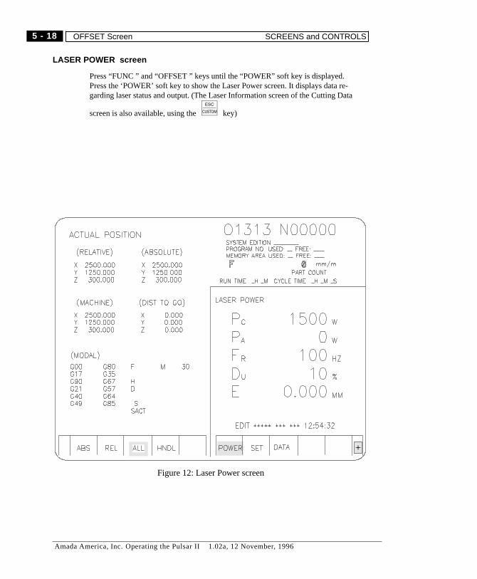
LASER POWER screen
Press “FUNC ” and “OFFSET ” keys until the “POWER” soft key is displayed.Press the ‘POWER’ soft key to show the Laser Power screen. It displays data re-garding laser status and output. (The Laser Information screen of the Cutting Data
screen is also available, using the key)
Figure 12: Laser Power screen
5 - 18
Amada America, Inc. Operating the Pulsar II 1.02a, 12 November, 1996
OFFSET Screen SCREENS and CONTROLS

LASER STATUS screen
From the Laser Power screen, press the soft key to display the STATUS softkey.
Press the “STATUS” soft key to show the status screen. This is a full screen dis-play showing current laser output and certain selected cutting parameters. Thelaser information screen of the Cutting Data screen is also available to monitorthe laser.
To return to the OFFSET screen, press the FUNC and OFFSET keys.
Use the key to activate the Cutting Data screen. (see chapter 7. )
Laser Setting screen
Press “FUNC” and “OFFSET” keys several times till the Laser Power screen isdisplayed. The POWER, SET, and DATA soft keys are displayed.
Press the SET soft key to display the laser setting screen, along with the SET andTRACE soft keys. This screen is not used - use the Cutting Data screens instead.(see chapter 7. ) Do not change the contents of this screen.
Trace Setting
The tracer setting screen is not used on Pulsar II- use the Cutting Data screens in-stead. (see chapter 7. ) Do not change the content of this screen.
From the Laser Setting screen, press the “TRACE” soft key to show the tracer set-ting screen.
Cutting data
Press the “FUNC ” and “OFFSET ” keys several times to show the “DATA” softkey. Press the “DATA” soft key to show the “manufacture data setting screen” orthe “pierce setting screen”. These screens are not used - use the Cutting Datascreens instead. (see chapter 7.)
Work Coordinate System screen
The work coordinate system setting screen is not used in this machine. Do notchange the contents of this screen.
Press the “WORK” soft key to show the work coordinate system setting screen .
Macro Variables display
This screen displays values of the Macro Variables used in various Amada pro-grams. Unless you are creating programs which use Macro Variables, this screencan be ignored.
Display the Work Coordinate System screen (see above) then press the softkey to display the MACRO soft key. The “Macro” soft key displays the macro vari-able screen. Do not change without consulting AMADA. Caution: If the contentsare changed, the machine may not operate normally or its precision may deterio-rate.
+
+
5 - 19
Amada America, Inc. Operating the Pulsar II 1.02a, 12 November, 1996
SCREENS and CONTROLS OFFSET Screen
MESSAGE Screen
Press the “FUNC ” and “MESSAGE ” keys to show the message screen. On themessage screen, the following three screens are selectable using soft keys.
Alarm message
This screen displays Fanuc alarms. For machine alarms, use the Cutting Datascreens (see page 5-3 for more information). Press the “ALARM” soft key to showthe alarm message screen. Usually, when NC alarm occurs, an alarm and its con-tent are displayed.
� Notes1. Refer to alarm section for the detailed content of alarm and the method of canceling
alarms.2. When an NC alarm occurs, you cannot continue auto-operation.
Operator message
Press the “MSG” soft key to show the operator message screen. When a messageoccurs, a prompt appears at the bottom of the screen.
Alarm history
Press the “HISTRY” soft key to show the alarm history screen. It displays the past25 NC alarms.
Press the PAGE UP, PAGE DOWN keys to change the page. Five alarms per pageare displayed
To clear alarm history:
1) Press the “HISTRY” soft key on the ALARMS HISTORY screen. The soft key displaythen changes, and shows “(OPRT)”.
2) Press the(OPRT) key to display theCLEAR soft key.3) Press theCLEAR soft key to clear alarms history.
4) Press to restore the previous soft key assignments.
GRAPHIC Screen
The graphics functions are not supported by Amada. Even though the basic con-touring instructions can be graphed, none of the special offsets, macros, patterns,and so forth are supported. Therefore, use of these screens is not recommended.
5 - 20
Amada America, Inc. Operating the Pulsar II 1.02a, 12 November, 1996
GRAPHIC Screen SCREENS and CONTROLS

HELP Screens
From any of the NC screens (not the Cutting Data screens) press the HELP key todisplay the (Fanuc) Help Screen.
From any of the Cutting Data Screens, use a function key (such as POS, PROG,etc.) to select an NC screen. Then press the HELP key.
On the Help Screen, a menu is displayed and the following three screens are avail-able by soft key selection:
1. ALARM DETAIL2. OPERATION METHOD3. PARAMETER CONTENTS
The ALARM DETAIL page displays the text message for any current alarm, and per-mits lookup of any valid alarm number.
The OPERATION METHODpages provide information about a variety of NC controloperator tasks.
The PARAMETER CONTENTSpages list major “groups” of parameters by function,and the parameter numbers that apply (for example) to I/O device setup or coordi-nate scaling.
Figure 13: Initial Help Menu
5 - 21
Amada America, Inc. Operating the Pulsar II 1.02a, 12 November, 1996
SCREENS and CONTROLS HELP Screens
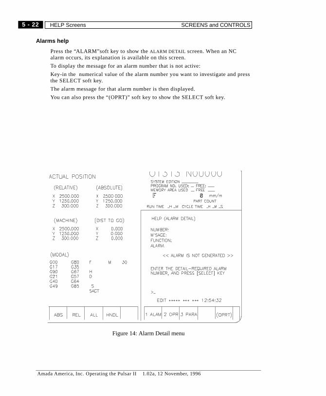
Alarms help
Press the “ALARM”soft key to show theALARM DETAIL screen. When an NCalarm occurs, its explanation is available on this screen.
To display the message for an alarm number that is not active:
Key-in the numerical value of the alarm number you want to investigate and pressthe SELECT soft key.
The alarm message for that alarm number is then displayed.
You can also press the “(OPRT)” soft key to show the SELECT soft key.
Figure 14: Alarm Detail menu
5 - 22
Amada America, Inc. Operating the Pulsar II 1.02a, 12 November, 1996
HELP Screens SCREENS and CONTROLS

Operations help
Press the “2 OPR” soft key to show theOPERATION METHODmenu screen
If you press soft key SELECT after control number you want to investigate, eachcontrol explanation screen is displayed. The page number is displayed on the righthand corner of the screen. Use thePAGE UP, PAGE DOWNkeys to select pages asneeded.
Figure 15: Operations Help menu
5 - 23
Amada America, Inc. Operating the Pulsar II 1.02a, 12 November, 1996
SCREENS and CONTROLS HELP Screens
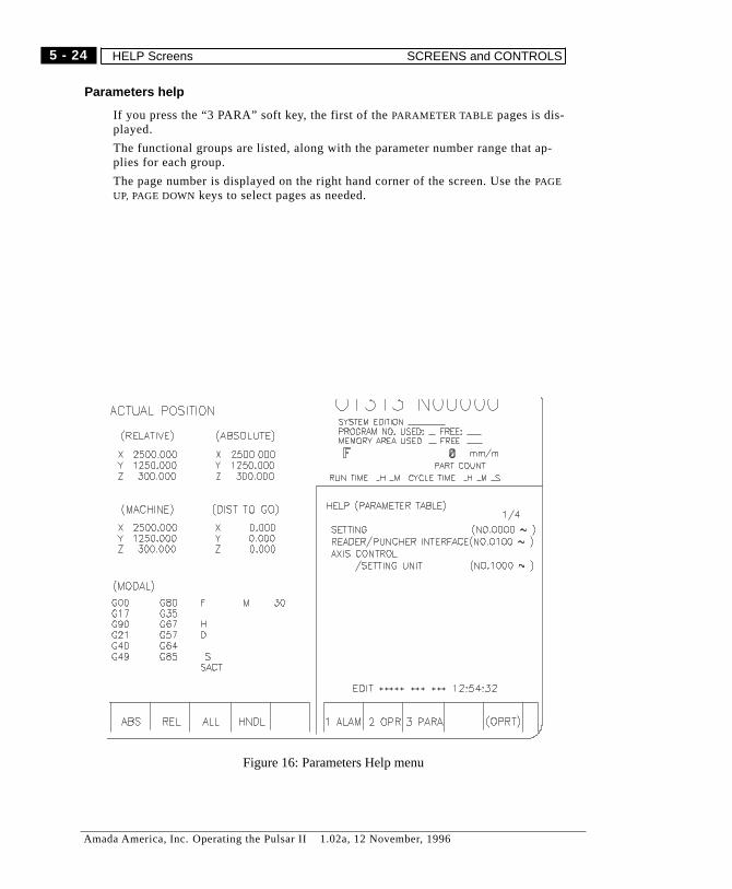
Parameters help
If you press the “3 PARA” soft key, the first of thePARAMETER TABLE pages is dis-played.
The functional groups are listed, along with the parameter number range that ap-plies for each group.
The page number is displayed on the right hand corner of the screen. Use thePAGE
UP, PAGE DOWNkeys to select pages as needed.
Figure 16: Parameters Help menu
5 - 24
Amada America, Inc. Operating the Pulsar II 1.02a, 12 November, 1996
HELP Screens SCREENS and CONTROLS
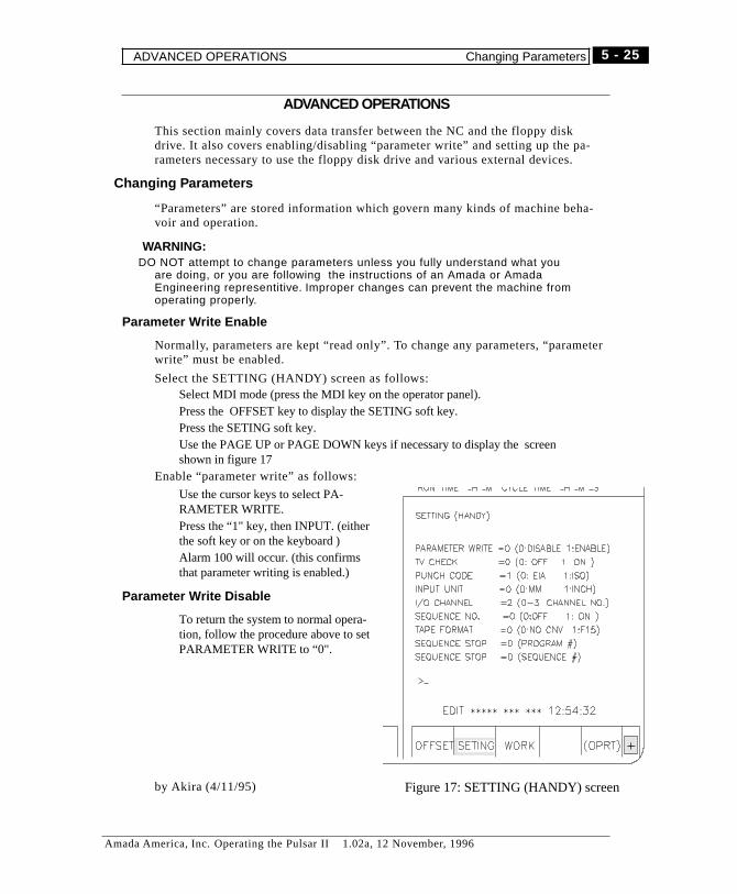
ADVANCED OPERATIONS
This section mainly covers data transfer between the NC and the floppy diskdrive. It also covers enabling/disabling “parameter write” and setting up the pa-rameters necessary to use the floppy disk drive and various external devices.
Changing Parameters
“Parameters” are stored information which govern many kinds of machine beha-voir and operation.
� WARNING:DO NOT attempt to change parameters unless you fully understand what you
are doing, or you are following the instructions of an Amada or AmadaEngineering representitive. Improper changes can prevent the machine fromoperating properly.
Parameter Write Enable
Normally, parameters are kept “read only”. To change any parameters, “parameterwrite” must be enabled.
Select the SETTING (HANDY) screen as follows:Select MDI mode (press the MDI key on the operator panel).Press the OFFSET key to display the SETING soft key.Press the SETING soft key.Use the PAGE UP or PAGE DOWN keys if necessary to display the screenshown in figure 17
Enable “parameter write” as follows:
Use the cursor keys to select PA-RAMETER WRITE.Press the “1" key, then INPUT. (eitherthe soft key or on the keyboard )Alarm 100 will occur. (this confirmsthat parameter writing is enabled.)
Parameter Write Disable
To return the system to normal opera-tion, follow the procedure above to setPARAMETER WRITE to “0".
by Akira (4/11/95) Figure 17: SETTING (HANDY) screen
5 - 25
Amada America, Inc. Operating the Pulsar II 1.02a, 12 November, 1996
ADVANCED OPERATIONS Changing Parameters
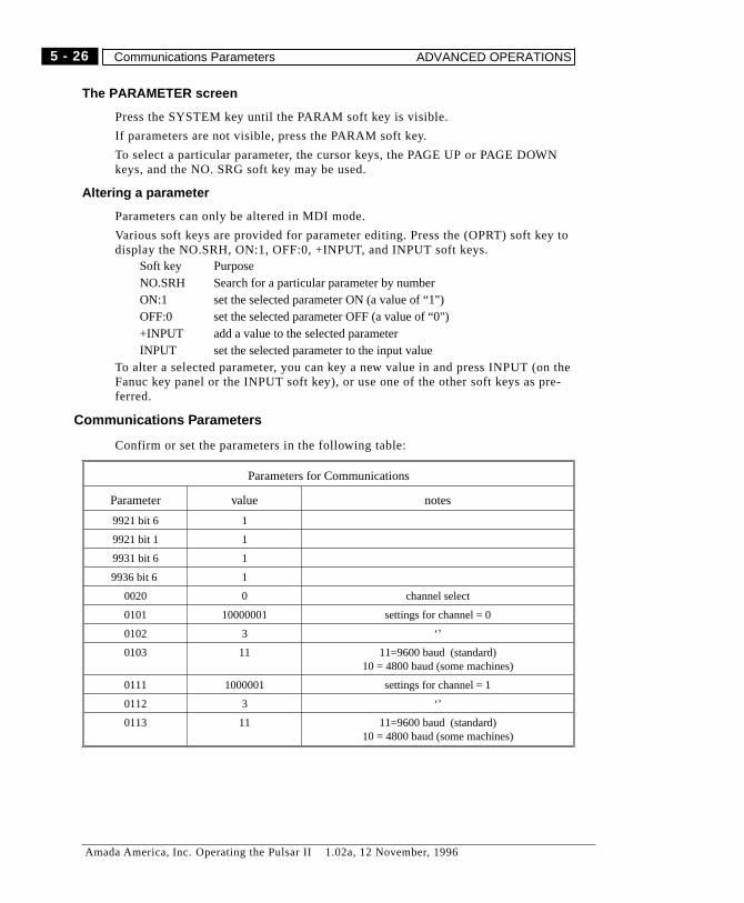
The PARAMETER screen
Press the SYSTEM key until the PARAM soft key is visible.
If parameters are not visible, press the PARAM soft key.
To select a particular parameter, the cursor keys, the PAGE UP or PAGE DOWNkeys, and the NO. SRG soft key may be used.
Altering a parameter
Parameters can only be altered in MDI mode.
Various soft keys are provided for parameter editing. Press the (OPRT) soft key todisplay the NO.SRH, ON:1, OFF:0, +INPUT, and INPUT soft keys.
Soft key PurposeNO.SRH Search for a particular parameter by numberON:1 set the selected parameter ON (a value of “1")OFF:0 set the selected parameter OFF (a value of “0")+INPUT add a value to the selected parameterINPUT set the selected parameter to the input value
To alter a selected parameter, you can key a new value in and press INPUT (on theFanuc key panel or the INPUT soft key), or use one of the other soft keys as pre-ferred.
Communications Parameters
Confirm or set the parameters in the following table:
Parameters for Communications
Parameter value notes
9921 bit 6 1
9921 bit 1 1
9931 bit 6 1
9936 bit 6 1
0020 0 channel select
0101 10000001 settings for channel = 0
0102 3 ‘’
0103 11 11=9600 baud (standard)10 = 4800 baud (some machines)
0111 1000001 settings for channel = 1
0112 3 ‘’
0113 11 11=9600 baud (standard)10 = 4800 baud (some machines)
5 - 26
Amada America, Inc. Operating the Pulsar II 1.02a, 12 November, 1996
Communications Parameters ADVANCED OPERATIONS

� NotesTransferring TO floppy, don’t need “parameter write” enabledFloppy must be in place and door closed, else get alarm 86
1
2
MDI ***** *** *** 12:54:32
PARAM DGNOS (OPRT)< PMC SYSTEM
MDI ***** *** *** 12:55:01
NO.SRH ON:1 INPUT+INPUT<
+
OFF:0 +
MDI ***** *** *** 12:55:18
PITCH< SV-PRM
3
(OPRT)
Parameter Edit soft keys
5 - 27
Amada America, Inc. Operating the Pulsar II 1.02a, 12 November, 1996
ADVANCED OPERATIONS Communications Parameters
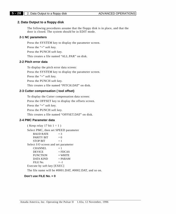
2. Data Output to a floppy disk
The following procedures assume that the floppy disk is in place, and that thedoor is closed. The system should be in EDIT mode.
2-1 NC parameters
Press the SYSTEM key to display the parameter screen.
Press the “+” soft key.
Press the PUNCH soft key.
This creates a file named “ALL.PAR” on disk.
2-2 Pitch error data
To display the pitch error data screen:
Press the SYSTEM key to display the parameter screen.
Press the “+” soft key.
Press the PUNCH soft key.
This creates a file named “PITCH.DAT” on disk.
2-3 Cutter compensation ( tool offset)
To display the Cutter compensation data screen:
Press the OFFSET key to display the offsets screen.
Press the “+” soft key.
Press the PUNCH soft key.
This creates a file named “OFFSET.DAT” on disk.
2-4 PMC Parameter data
( Keep relay 17 bit 1 = 1 )
Select PMC, then set SPEED parameterBAUD RATE = 3PARITY BIT = 0STOP BIT = 1
Select I/O screen and set parameterCHANNEL = 1DEVICE = FDCASFUNCTION = WRITEDATA KIND = PARAMFILE No. = -1
Execute by soft key [EXEC]
The file name will be #0001.DAT, #0002.DAT, and so on.
� Don’t use FILE No. = 0
5 - 28
Amada America, Inc. Operating the Pulsar II 1.02a, 12 November, 1996
2. Data Output to a floppy disk ADVANCED OPERATIONS
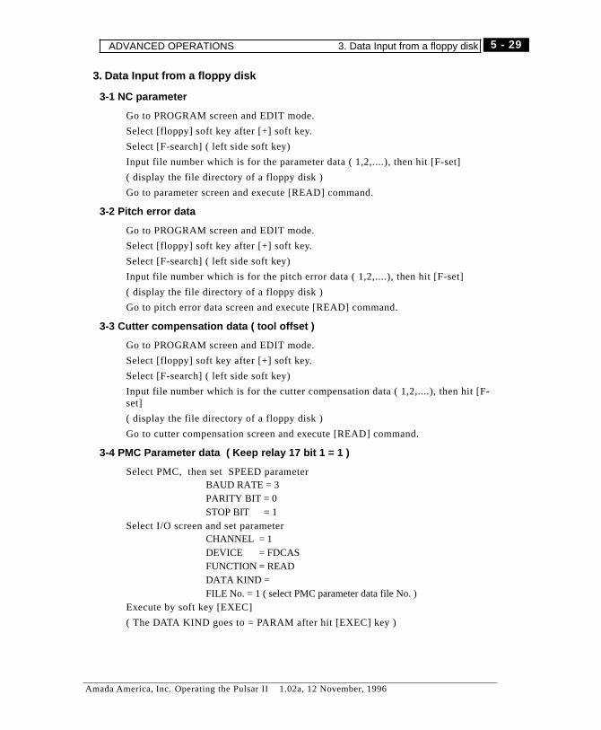
3. Data Input from a floppy disk
3-1 NC parameter
Go to PROGRAM screen and EDIT mode.
Select [floppy] soft key after [+] soft key.
Select [F-search] ( left side soft key)
Input file number which is for the parameter data ( 1,2,....), then hit [F-set]
( display the file directory of a floppy disk )
Go to parameter screen and execute [READ] command.
3-2 Pitch error data
Go to PROGRAM screen and EDIT mode.
Select [floppy] soft key after [+] soft key.
Select [F-search] ( left side soft key)
Input file number which is for the pitch error data ( 1,2,....), then hit [F-set]
( display the file directory of a floppy disk )
Go to pitch error data screen and execute [READ] command.
3-3 Cutter compensation data ( tool offset )
Go to PROGRAM screen and EDIT mode.
Select [floppy] soft key after [+] soft key.
Select [F-search] ( left side soft key)
Input file number which is for the cutter compensation data ( 1,2,....), then hit [F-set]
( display the file directory of a floppy disk )
Go to cutter compensation screen and execute [READ] command.
3-4 PMC Parameter data ( Keep relay 17 bit 1 = 1 )
Select PMC, then set SPEED parameterBAUD RATE = 3PARITY BIT = 0STOP BIT = 1
Select I/O screen and set parameterCHANNEL = 1DEVICE = FDCASFUNCTION = READDATA KIND =FILE No. = 1 ( select PMC parameter data file No. )
Execute by soft key [EXEC]
( The DATA KIND goes to = PARAM after hit [EXEC] key )
5 - 29
Amada America, Inc. Operating the Pulsar II 1.02a, 12 November, 1996
ADVANCED OPERATIONS 3. Data Input from a floppy disk

Notes
5 - 30
Amada America, Inc. Operating the Pulsar II 1.02a, 12 November, 1996
3. Data Input from a floppy disk ADVANCED OPERATIONS

Chapter 6
Program Storage and editing
Amada America, Inc. Operating the Pulsar II 1.02a, 12 November, 1996

Notes
6 - 2
Amada America, Inc. Operating the Pulsar II 1.02a, 12 November, 1996

Overview
This chapter covers creation, selection, editing, and transfer of programs to andfrom the NC. For programming codes and techniques, see the Programming Man-ual. For machine operation, see chapters 3, 4.
Each program in the NC is identified by a program number. The available num-bers for user programs are 0001 to 8999.
Program numbers 9000 to 9999 are reserved for Amada programs.
Program number 0000 may be used in certain Extended Edit operations, andshould be left as a “scratchpad” area.
If, while executing a program, you stop operation temporarily by single block stopor stop and alter the program (insert, delete, or change any data within it) you can-not continue to execute the program. After editing a program, always press“RESET before attempting to re-run it.
Preparing to Edit
When you store a program or edit it in NC memory, do the following:
1) Turn the “memory protect” key OFF (operator panel)
2) Select EDIT mode
3) Press the FUNC and PROG keys to display the program screen. Press thePRGRM soft key (if needed) to display the program listing.
4) Press the “(OPRT)” soft key to change the soft keys for editing. (Even if youdon’t press soft key “(OPRT)”, the soft keys change for editing when any of theaddress or numeric keys are pressed).
5) When you transfer data to or from a device such as Fanuc’s “Handy File”, re-member to set the input or output mode. (SETTING screen)
The following section assumes that the NC is in EDIT mode with “memory pro-tect” OFF.
� Notes
Program numbers “08000 ~ 08999" can be protected by a parameter, and arerecommended for programs which are to be kept in the NC and not edited.
Program numbers “09000 ~ 09999" are reserved by Amada for custom/machineprograms.
6 - 3
Amada America, Inc. Operating the Pulsar II 1.02a, 12 November, 1996
Overview
Program Selection
To search through programs in the memory, you can view the program directory(LIB soft key), search by program number, or just display programs one-at-a-timeuntil you find the right one.
Select by Program Number
(In EDIT or AUTO mode only)
Input a program number you want to select by pressing the O key (not zero) andthe numbers. Example: O1313
Press the “O SRCH” soft key. (You can also press the “SRH↓” soft key or the“DOWN” cursor key instead of “O SRH”.
After finishing search, the program number and its name (if found) are displayedon the upper part of the CRT.
Program Scan
Press soft key “O SRCH” repeatedly to display each program in memory one byone. After all program numbers registered are displayed, it goes back to the firstprogram. They are displayed in the order registered in memory, not by programnumber.
6 - 4
Amada America, Inc. Operating the Pulsar II 1.02a, 12 November, 1996
Program Selection Preparing to Edit
Program Handling
Programs may be created off-line and transferred into the NC, or simply keyed-inat the MDI/CRT panel.
Creating a Program
Creating a program at the MDI/CRT panel
Press “O” (not zero), and key the desired program number in. Press the INSERTkey to store the program number in memory.
Input program data word by word by using the “Address/Numeric ” keys as neces-sary. the keyboard input goes to the “key input buffer” and is displayed on screen.
Press INSERT key to transfer contents of the “key input buffer”to program mem-ory
Continue to key-in and insert necessary instructions to create the program.
Program Delete
Once the NC deletes a program, no recovery is possible. When in doubt, be surethat a backup exists off-line before deleting a program from the NC.
Deleting One Program
You can delete one program registered in the memory.
Input the program number to be deleted by keying in “O” and the number..
If you press DELETE key, the program whose number was input is deleted. If youdelete a program, the next program (in memory) is displayed.
Deleting all programs
Key-in “O-9999"
� Warning: This kills ALL programs in memory.
Press DELETE key to delete all programs in memory.
6 - 5
Amada America, Inc. Operating the Pulsar II 1.02a, 12 November, 1996
Preparing to Edit Program Handling
Edit Procedures
This section covers basics of program editing. For further information, refer to theFanuc Series 16 LA (or 16 LB, as appropriate) Operator Manual.
Cursor Forward
If you press the left/right arrow “Cursor←, → ” the cursor moves word by word.
If you press “Cursor→ ”, the cursor moves word by word to the right.
If you press “Cursor← ”, the cursor moves word by word to the left.
If you keep pressing “Cursor←, → ”, the cursor keeps moving.
Line Forward
If you press “Cursor UP, DOWN”, the cursor moves one row at a time:
“Cursor DOWN” moves the cursor one row down
G00 When G01 X120 Y30; If you press “Cursor DOWN”,
G00 G01 X120 Y130;
“Cursor UP” moves the cursor one row up
If you press and hold the Cursor “DOWN” or “UP ” key, the cursor keeps moving.
Page Forward
If you press “Page key DOWN”, the screen changes to the next one and the cursormoves to the beginning word.
If you press “Page key UP”, the screen changes to the previous one and cursormoves to the beginning word.
If you keep pressing “Page key DOWN, UP”, the pages change continuously.
Return to Top of Program
There are two ways to return the cursor to the beginning of a program.
Press the “Home” soft key.This is effective in EDIT mode. The cursor goes back to the beginning of the pro-gram and the content of the program is displayed form its beginning.
Press the RESET key.This is effective in MEMORY operation mode or EDIT mode. In background edit,there is no HOME. If the foreground program is being executed, its executionstops.
6 - 6
Amada America, Inc. Operating the Pulsar II 1.02a, 12 November, 1996
Program Handling Edit Procedures
Word Search
If you press the “SRH↓” soft key , the cursor searches for a word designated tothe forward direction.
In the above program, input “E” with key and press “SRH↓”, and then the searchbegins. (You can use “Cursor key DOWN, instead of ”SRH↓“).
Once the search is completed, the cursor is displayed on “E001".
When you search for “M30" in the same program, input ”M30" with key andpress “SRH↓” and then the search begins. (You can use “Cursor Key DOWN” in-stead of “SRH↓”.)
Once the search is completed, the cursor is displayed on “M30".
� NoteYou cannot search for “M30" by inputting only ”M3" with key.If you press soft key “Search UP”, the cursor searches for a word designated to
the backward direction.In the above program, when you search for “G90", input ”G90" with key and
press “Search UP”. Then the search begins. (You can use “Cursor UP”instead of “Search UP”)
Once the search is completed, the cursor is displayed on “G90".
Word Change
How to change words in a stored program:
G111 X150 Y80 I120 J10;Move the cursor to a word you want to change with, say “Word Search”. In thiscase, we want to change I20 to I18, move the cursor to “I20"Input the word you want to change with key. In this case, input “I18" with key.Press ALTER key and “I20" is changed to ”I18".
G111 X150 Y80 I18 J10;
Inserting Word(s)
Here’s how to insert a word between two existing words:
G111 X150 Y80 I18 J10;Move the cursor to a word immediate before the place you want to insert by usingsay, ‘Word search’. Since we want to insert “R3" between ”J10" and “;”, move thecursor to “J10".Input a word you want to insert with key. In this case, input “R3" with key.Press INSERT key and “R3" is inserted
G111 X150 Y80 I18 J10 123;
6 - 7
Amada America, Inc. Operating the Pulsar II 1.02a, 12 November, 1996
Edit Procedures Program Handling
Word Deletion
Word Delete
Here’s how to delete a single word from a stored program:G111 X150 Y80 J10 R3; (before)
Move the cursor to a word you want to delete. To delete “R3", move the cursor sothat ”R3" is selected.
Press DELETE key and “R3" is deleted.G111 X150 Y80 I18 J10; (after)
Delete to EOB
Here’s how to delete unnecessary words from a certain word to “EOB” (“;”).G111 X150 Y80 I18 J10 25 R3; (before)
G00 X100 Y-5;E003
Move the cursor to a word where you want to start deleting. In this example, wewant to delete from “J10" to ”;". Therefore, move the cursor to “J10".
Input “;” with key and press DELETE key and the words form “J10" to ”;" are de-leted.
G111 X150 Y80 I18; (after)
G00 X100 Y-5;E003
Deleting several blocks
To delete everything from the cursor position to a block where a designated se-quence number is:
Move the cursor to the beginning of a block that you want to start deleting by, say,“word search”. In this example, since we want to delete blocks from (I) to (II),move the cursor to the beginning of the blockInput “N20" with key and press DELETE key and the blocks from (I) to (II) are de-leted. The cursor moves to the next block.
� NoteWhen you want to delete from the middle of a block, not from the beginning,
over several blocks, the words before the designated cursor position are left.After the deletion, since the next block to the designated sequence numberis connected with the left word, insert “EOB” (“;”).
6 - 8
Amada America, Inc. Operating the Pulsar II 1.02a, 12 November, 1996
Program Handling Edit Procedures

Deleting to a designated word
To delete a group of words from a word to a designated in a blockMove the cursor to a word you want to start deleting. In this example, since wewant to delete the words from “G00" of (I) to ”X25" of (II), move the cursor to“G00" of (I)Input “X25" for the last word you want to delete with key and press the DELETEkey. The words from the cursor position to the first word designated is deleted..The cursor moves to the next word beyond the deleted items.
� Note1. The first matching word ends the search/deletion.2. When the word you start deleting and the word designated to delete are in
the middle of the block, the words before and after the words deleted areleft as they are. After deleting, they are connected. If the codes of the samegroup overlap, insert “EOB” (“;”).
G93 X.5 Y29.5 Z.06;G00 G42 X-.2 Y0;M103;G01 X6;G00; (I)
X14.5 Y4.;X25 Y4; (II)
X3 Y6;X0;Y0;
Figure 1: "delete to word " before
G93 X.5 Y29.5 Z.06;G00 G42 X-.2 Y0;M103;G01 X6;Y4; (II)
X3 Y6;X0;Y0;
Figure 2: "delete to word " after
6 - 9
Amada America, Inc. Operating the Pulsar II 1.02a, 12 November, 1996
Edit Procedures Program Handling
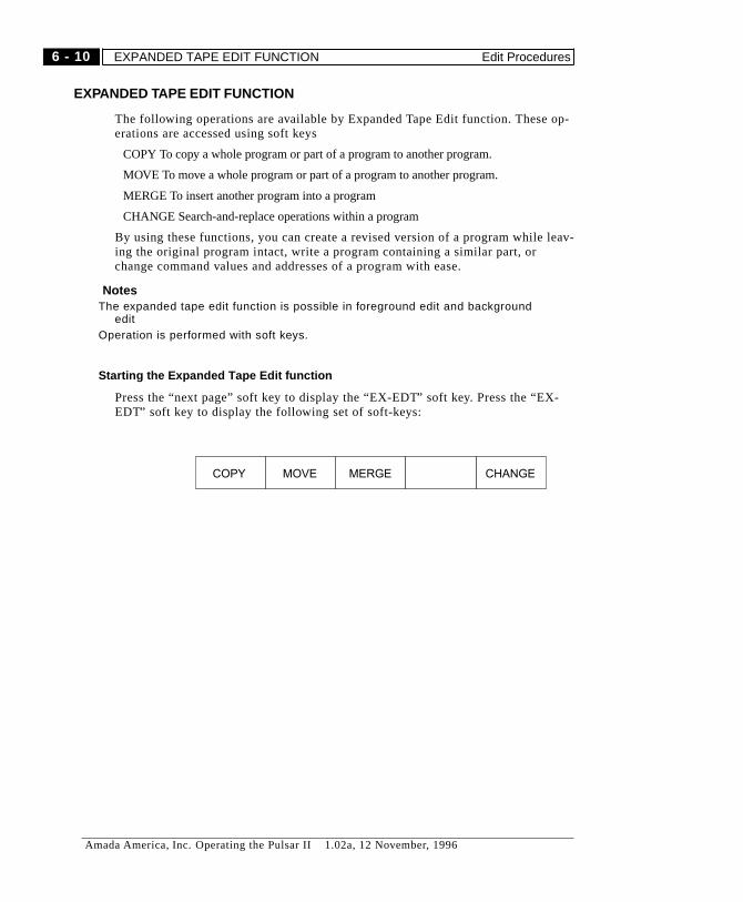
EXPANDED TAPE EDIT FUNCTION
The following operations are available by Expanded Tape Edit function. These op-erations are accessed using soft keys
COPY To copy a whole program or part of a program to another program.
MOVE To move a whole program or part of a program to another program.
MERGE To insert another program into a program
CHANGE Search-and-replace operations within a program
By using these functions, you can create a revised version of a program while leav-ing the original program intact, write a program containing a similar part, orchange command values and addresses of a program with ease.
� NotesThe expanded tape edit function is possible in foreground edit and background
editOperation is performed with soft keys.
Starting the Expanded Tape Edit function
Press the “next page” soft key to display the “EX-EDT” soft key. Press the “EX-EDT” soft key to display the following set of soft-keys:
MOVECOPY CHANGEMERGE
6 - 10
Amada America, Inc. Operating the Pulsar II 1.02a, 12 November, 1996
EXPANDED TAPE EDIT FUNCTION Edit Procedures

Copying a Program
Use the COPY soft key to copy a program. The soft keys change as follows:
Key PurposeCSR ~ Marks beginning of range to copy or move~ CSR Marks the END of the range of instructions to copy or move.~ BTTM End of program becomes end of range.ALL Copy or move the entire program.
Copying a whole program
a) Press soft key “COPY”
b) Press soft key “ALL”
c) Input the new program number with numeric keys
d) Press INPUT on the CRT/MDI keypad.
e) Press the “EXEC” soft key.
� Notes1. If you press the “EXEC” soft key without designating a program number, the
selected instructions are copied into program 00000. Any previous programin 00000 is overwritten.
2. When the system is waiting for a program number input, you can not editanything.
MOVECOPY CHANGEMERGE
~ CSRCSR ~ ALL~ BTTM
EXEC
6 - 11
Amada America, Inc. Operating the Pulsar II 1.02a, 12 November, 1996
Edit Procedures EXPANDED TAPE EDIT FUNCTION

Copying part of a program
a) Press the “COPY” soft key.
b) Move the insertion point to the BEGINNING of the instructions to copy.
c) Press the “CSR ~” soft key.
d) Move the insertion point to the END of the instructions to copy.
e) Press the “ ~ CSR” or “~ BTTM” soft key.
f) Input the program number with numeric key, and press INPUT.
3) Press the “EXEC” soft key.
� Notes1. If you press the “EXEC” soft key without designating a program number, the
selected instructions are copied into program 00000. Any previous programin 00000 is overwritten.
2. You can not edit while the system is waiting for a program number input.3. Only an unused program number may be copied to.4. You can set an edit range start point (“CSR ~”) repeatedly until setting an
edit range finish point (“~ CSR” or “~ BTTM”)5. The edit range start point and the edit range finish point are effective until
the following operation is performed.When operation except for address search, word search, cursor up-down, page up- down,
and return to the program beginning (home) is performed after setting a start point or afinish point.
When going back to operation selection after setting a start point or a finish point.
6 - 12
Amada America, Inc. Operating the Pulsar II 1.02a, 12 November, 1996
EXPANDED TAPE EDIT FUNCTION Edit Procedures
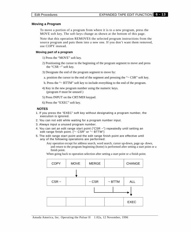
Moving a Program
To move a portion of a program from where it is to a new program, press theMOVE soft key. The soft keys change as shown at the bottom of this page.
Note that this operation REMOVES the selected program instructions from thesource program and puts them into a new one. If you don’t want them removed,use COPY instead.
Moving part of a program
1) Press the “MOVE” soft key.
2) Positioning the cursor to the beginning of the program segment to move and pressthe “CSR ~” soft key.
3) Designate the end of the program segment to move by:
a. position the cursor to the end of the segment and pressing the “~ CSR” soft key.
b. Press the “~ BTTM” soft key to include everything to the end of the program.
4) Key in the new program number using the numeric keys.(program # must be unused )
5) Press INPUT on the CRT/MDI keypad.
6) Press the “EXEC” soft key.
� NOTES1. If you press the “EXEC” soft key without designating a program number, the
execution is ignored.2. You can not edit while waiting for a program number input.3. Always input a unused program number.4. You can set an edit range start point (“CSR ~”) repeatedly until setting an
edit range finish point. (“~ CSR” or “~ BTTM”)5. The edit range start point and the edit range finish point are effective until
any of the following operations are performed:Any operation except for address search, word search, cursor up-down, page up- down,
and return to the program beginning (home) is performed after setting a start point or afinish point.
When going back to operation selection after setting a start point or a finish point.
MOVECOPY CHANGEMERGE
~ CSRCSR ~ ALL~ BTTM
EXEC
6 - 13
Amada America, Inc. Operating the Pulsar II 1.02a, 12 November, 1996
Edit Procedures EXPANDED TAPE EDIT FUNCTION
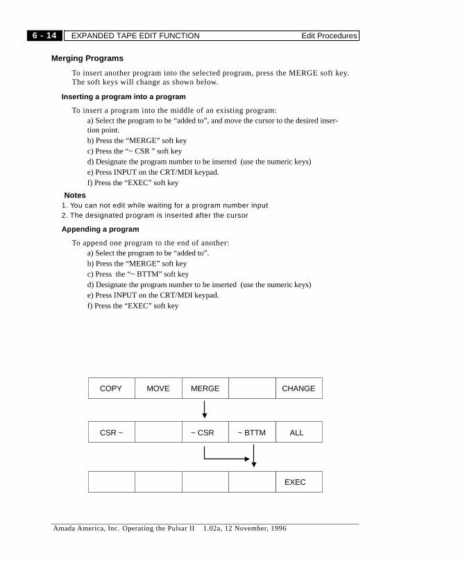
Merging Programs
To insert another program into the selected program, press the MERGE soft key.The soft keys will change as shown below.
Inserting a program into a program
To insert a program into the middle of an existing program:a) Select the program to be “added to”, and move the cursor to the desired inser-tion point.b) Press the “MERGE” soft keyc) Press the “~ CSR ” soft keyd) Designate the program number to be inserted (use the numeric keys)e) Press INPUT on the CRT/MDI keypad.f) Press the “EXEC” soft key
� Notes1. You can not edit while waiting for a program number input2. The designated program is inserted after the cursor
Appending a program
To append one program to the end of another:a) Select the program to be “added to”.b) Press the “MERGE” soft keyc) Press the “~ BTTM” soft keyd) Designate the program number to be inserted (use the numeric keys)e) Press INPUT on the CRT/MDI keypad.f) Press the “EXEC” soft key
MOVECOPY CHANGEMERGE
~ CSRCSR ~ ALL~ BTTM
EXEC
6 - 14
Amada America, Inc. Operating the Pulsar II 1.02a, 12 November, 1996
EXPANDED TAPE EDIT FUNCTION Edit Procedures
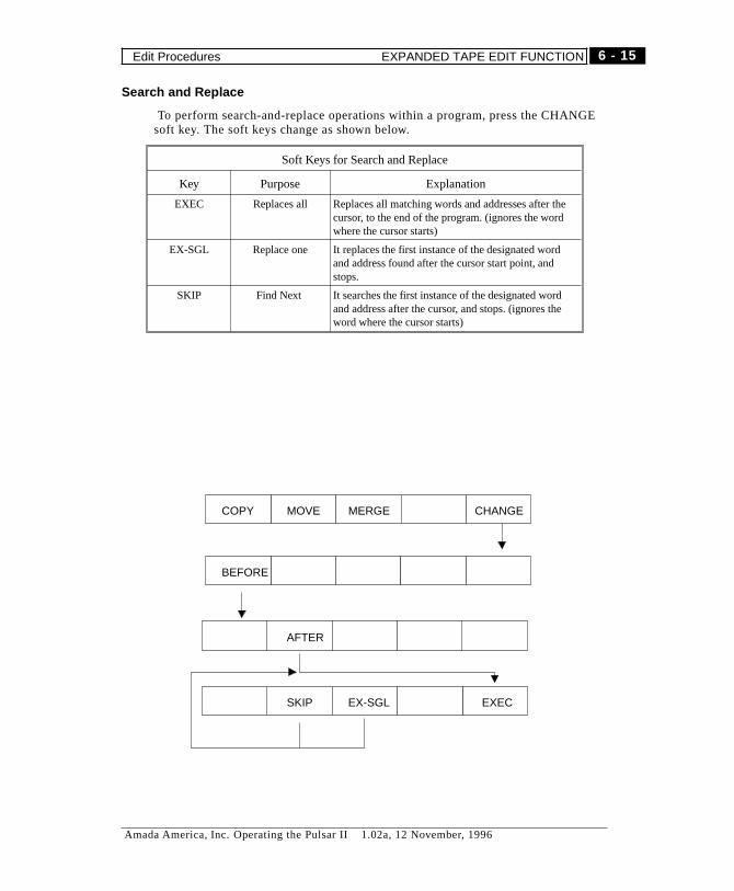
Search and Replace
To perform search-and-replace operations within a program, press the CHANGEsoft key. The soft keys change as shown below.
Soft Keys for Search and Replace
Key Purpose Explanation
EXEC Replaces all Replaces all matching words and addresses after thecursor, to the end of the program. (ignores the wordwhere the cursor starts)
EX-SGL Replace one It replaces the first instance of the designated wordand address found after the cursor start point, andstops.
SKIP Find Next It searches the first instance of the designated wordand address after the cursor, and stops. (ignores theword where the cursor starts)
MOVECOPY CHANGEMERGE
BEFORE
SKIP
AFTER
EXECEX-SGL
6 - 15
Amada America, Inc. Operating the Pulsar II 1.02a, 12 November, 1996
Edit Procedures EXPANDED TAPE EDIT FUNCTION

How to replace all words designated after the cursor
a) Press soft key “CHANGE”b) Input words you want to replace with data input keyc) Press soft key “Before replace”d) Input a word after replacing with data input keye) Press soft key “After replace”f) Press soft key “EXEC”
� Notes1. This operation always starts at the next word after the cursor. To operate on
the entire program, move he cursor to the beginning of the program first.2. You can designate maximum 40 words for starting replace and after replace
words.3. Can change part of word if desired, as changing “X” to “Y”. This will change
“G00 X1000;” to “G00 Y1000;”
How to replace designated words one by one
a) Press soft key “CHANGE”b) Input words you want to replace with data input keyc) Press soft key “Before replace”d) Input the word after replace with data input keye) Press soft key “After replace”f) Press soft key “EX-SGL”g) When you do the same replacement, repeat f)
� Notes1. Replace starts from the words next to the cursor.2. You can designate maximum 40 words for starting replace and after replace
words.
6 - 16
Amada America, Inc. Operating the Pulsar II 1.02a, 12 November, 1996
EXPANDED TAPE EDIT FUNCTION Edit Procedures

Search and Replace with Confirm
a) Press soft key “CHANGE”
b) Input the words you want to replace with data input keys
c) Press soft key “Before replace”
d) Input the words after replace with data input keys.
e) Press soft key “After replace”
f) Press soft key “SKIP”
g) When you replace a word where the cursor stops, press the cursor up key andthen press soft key “EX-SGL”.
Perform f) after replace. When you search next word without replacing, perform f).
� Caution1. Replacement starts from the word next to the cursor.2. Replace start and after replace words are designated with maximum 40
words.
6 - 17
Amada America, Inc. Operating the Pulsar II 1.02a, 12 November, 1996
Edit Procedures EXPANDED TAPE EDIT FUNCTION
BACKGROUND EDIT
The NC system permits program transfer and editing under any operation modeconditions on the NC. (whether or not it is during auto operation). When operationmode is EDIT mode, it is called “Foreground Edit”. On the other hand, when NCis operation at any mode except for EDIT mode, an Edit performed in the back-ground is called “Background Edit (BG Edit) or Back Edit”. (Background Edit ispossible even when Foreground is in EDIT mode.
NC alarms which occurs when loading and editing a program in the backgrounddo not affect any operation in the foreground. Background editing is not affectedby alarms from the foreground. You cannot execute a program being edited in thebackground.
Starting a Background Edit
On the program display screen, press soft key “BG edit” and then the backgroundedit starts. The display at the upper changeable portion changes from “Program”to “Program (BG-EDIT)” which indicates that the background editing is in pro-gress. Program edit is the same as the program edit in the foreground.
Finishing a Background Edit
Finish a background editing by pressing the “BG finish” soft key.
� Notes1. You cannot background edit a program that is currently selected in the
foreground. If this is attempted, BP/S alarm (140) occurs.2. When a program is in background edit and is called as a subprogram in the
foreground, P/S alarm (78) occurs in the foreground.3. You cannot delete the whole program while editing in the background4. You can cancel NC alarm occurred in the background edit by pressing any
key. However, if you press RESET by mistake the operation in theforeground is reset.
6 - 18
Amada America, Inc. Operating the Pulsar II 1.02a, 12 November, 1996
BACKGROUND EDIT Edit Procedures

Loading and Saving Programs
This section covers use of the Fanuc internal floppy drive unit. This unit is foundon Pulsar and Altair machines which have the Fanuc 16-LB control. The floppydrive unit is actually an “Internal Handy File”, similar to the external “HandyFile” unit which was optional for the machines with F16-LA control.
Program transfer operations may be done in EDIT mode. To read programs intothe NC, the PROGRAM PROTECT key must be OFF.
The FLOPPY operations screen is accessed using soft keys. The initial sequenceis shown at the bottom of this page.
� NOTE:If the floppy drive cover door is not closed, Error 86 “DR SIGNAL OFF” will
occur when you try to access the floppy.
Setup
For setup and related information, see page 5-26.
For more insormation on NC screens and soft key assignments, see page 5-11.
1
2
3
EDIT ***** *** *** 12:54:32
PGRM L(OPRT) +
EDIT ***** *** *** 12:54:43
+
EDIT ***** *** *** 12:55:02
PRGRM DIR (OPRT)
FLOPPY
return toPROG screen
for directoryof floppy
for READ,PUNCH, etc.
(OPRT)
Figure 3: Soft-Key sequence
6 - 19
Amada America, Inc. Operating the Pulsar II 1.02a, 12 November, 1996
Loading and Saving Programs BACKGROUND EDIT
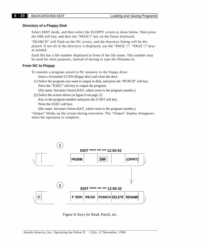
Directory of a Floppy Disk
Select EDIT mode, and then select the FLOPPY screen as show below. Then pressthe DIR soft key, and then the “PAGE⇓” key on the Fanuc keyboard.
“SEARCH” will flash on the NC screen, and the directory listing will be dis-played. If not all of the directory is displayed, use the “PAGE⇓”, “PAGE ⇑” keysas needed.
Each file has a file number displayed in front of the file name. This number maybe used for most purposes, instead of having to type the filename in.
From NC to Floppy
To transfer a program stored in NC memory to the floppy drive:Insert a formatted 3.5 FD (floppy disc) and close the door.
(1) Select the program you want to output to disk, and press the “PUNCH” soft key.Press the “EXEC” soft key to output the program.(file name becomes Onnnn.DAT, wherennnnis the program number.)
(2) Select the screen shown in figure 6 on page 22.Key in the program number and press the O SET soft key.Press the EXEC soft key.(file name becomes Onnnn.DAT, wherennnnis the program number.)
“Output” blinks on the screen during execution. The “Output” display disappearswhen the operation is complete.
1
2
<
EDIT ***** *** *** 12:55:02
PRGRM DIR (OPRT)
EDIT ***** *** *** 12:55:32
F SRH READ RENAMEPUNCH DELETE
Figure 4: Keys for Read, Punch, etc.
6 - 20
Amada America, Inc. Operating the Pulsar II 1.02a, 12 November, 1996
BACKGROUND EDIT Loading and Saving Programs
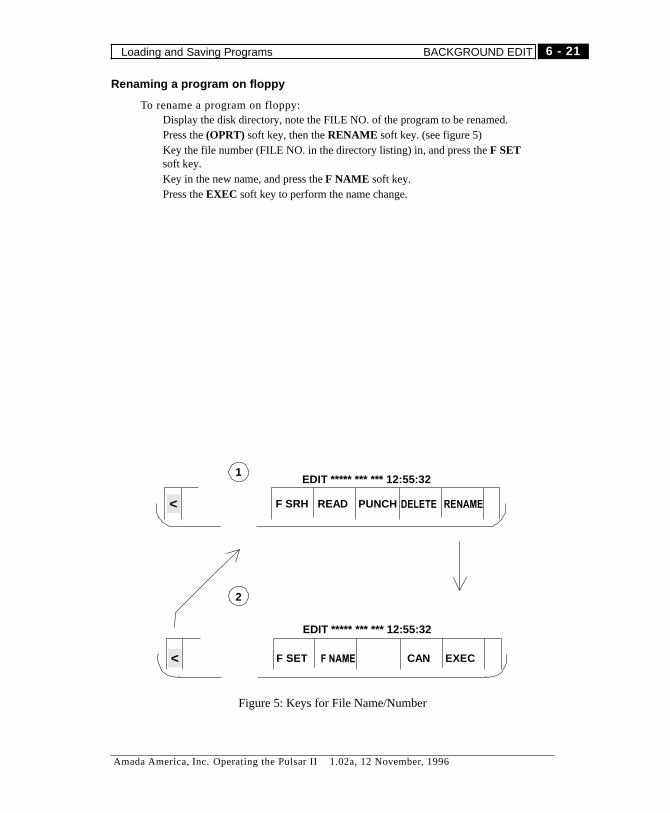
Renaming a program on floppy
To rename a program on floppy:Display the disk directory, note the FILE NO. of the program to be renamed.Press the(OPRT) soft key, then theRENAME soft key. (see figure 5)Key the file number (FILE NO. in the directory listing) in, and press theF SETsoft key.Key in the new name, and press theF NAME soft key.Press theEXEC soft key to perform the name change.
1
2
EDIT ***** *** *** 12:55:32
F SRH READ RENAME< PUNCH DELETE
EDIT ***** *** *** 12:55:32
F SET F NAME EXECCAN<
Figure 5: Keys for File Name/Number
6 - 21
Amada America, Inc. Operating the Pulsar II 1.02a, 12 November, 1996
Loading and Saving Programs BACKGROUND EDIT
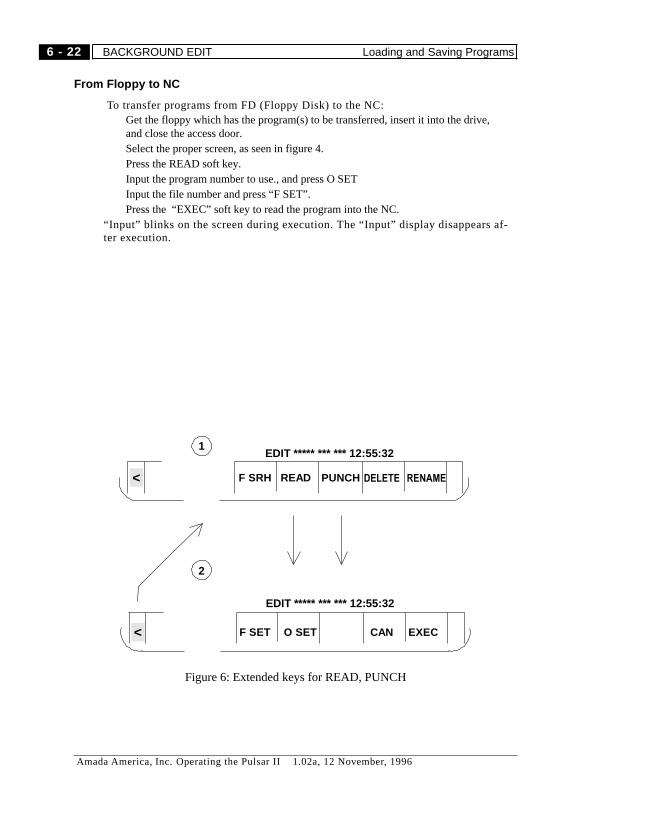
From Floppy to NC
To transfer programs from FD (Floppy Disk) to the NC:Get the floppy which has the program(s) to be transferred, insert it into the drive,and close the access door.Select the proper screen, as seen in figure 4.Press the READ soft key.Input the program number to use., and press O SETInput the file number and press “F SET”.Press the “EXEC” soft key to read the program into the NC.
“Input” blinks on the screen during execution. The “Input” display disappears af-ter execution.
1
2
EDIT ***** *** *** 12:55:32
F SRH READ RENAME< PUNCH DELETE
EDIT ***** *** *** 12:55:32
F SET O SET EXECCAN<
Figure 6: Extended keys for READ, PUNCH
6 - 22
Amada America, Inc. Operating the Pulsar II 1.02a, 12 November, 1996
BACKGROUND EDIT Loading and Saving Programs
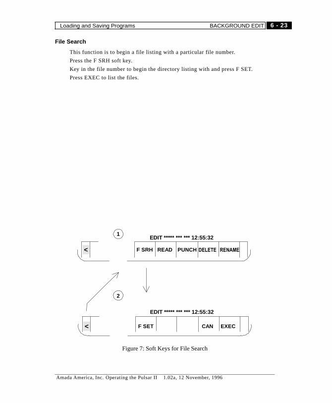
File Search
This function is to begin a file listing with a particular file number.
Press the F SRH soft key.
Key in the file number to begin the directory listing with and press F SET.
Press EXEC to list the files.
1
2
EDIT ***** *** *** 12:55:32
F SRH READ RENAME< PUNCH DELETE
EDIT ***** *** *** 12:55:32
F SET EXECCAN<
Figure 7: Soft Keys for File Search
6 - 23
Amada America, Inc. Operating the Pulsar II 1.02a, 12 November, 1996
Loading and Saving Programs BACKGROUND EDIT

Notes
6 - 24
Amada America, Inc. Operating the Pulsar II 1.02a, 12 November, 1996
BACKGROUND EDIT Loading and Saving Programs

Chapter 7
Cutting Data Screens
Amada America, Inc. Operating the Pulsar II 1.02a, 12 November, 1996

Notes
7 - 2
Amada America, Inc. Operating the Pulsar II 1.02a, 12 November, 1996

OVERVIEW
The Cutting Data Screens deal with Amada’s Cutting Data Library, machine pa-rameters, and machine alarms.
The Cutting Data Screens are independent from the NC screens. They are selectedusing theCUSTOM key, and include the following 6 screens plus one split screen(laser information screen)
SCREEN PURPOSE Page
Cutting Condition Permits display and editing of cutting data (full screen or splitwith Laser Information )
12
Pierce Condition Permits display and editing of piercing data (full screen or splitwith Laser Information )
18
Edge Condition Permits display and editing of edge data. (full screen or splitwith Laser Information )
24
Material List Lists materials by various categories, permits loading andsaving data. (full screen or split with Laser Information )
30
Parameter To set parameters relating to sensor operation and Z-axis retract.(full screen )
36
Alarm Displays Amada’s machine alarms. Full screen. 37
Laser Information (split) Displays the present condition of the laser. Available withCutting, Pierce, and Edge Condition screens, and the MaterialList screen.
5
Screen Selection
When the Cutting Data Screens are active, the HELP key toggles between theAlarm screen and the other most recently selected Cutting Data Screen.
To select the Cutting Data Screens
Press theCUSTOM key to go from any NC screen to the Cutting Data Screen.The most recently displayed Cutting Data Screen is shown when you go from NCscreen to Cutting Data Screen.
� NOTE:Pressing theCUSTOMkey again blanks the NC screen. If the screen is completelyblank for more than ten seconds or so, and power is on, press the CUSTOM keyfirmly for 1-2 seconds and release it.
To return from a Cutting Data Screen to an NC screen
Press theFUNC key and any function key (POS, SYSTEM, PROG, OFFSET, MESSAGE,or GRAPH) to go from a Cutting Data Screen to that NC screen.
7 - 3
Amada America, Inc. Operating the Pulsar II 1.02a, 12 November, 1996
OVERVIEW Screen Selection
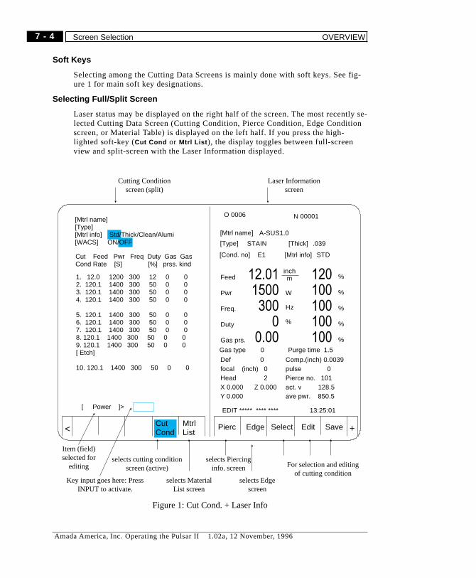
Soft Keys
Selecting among the Cutting Data Screens is mainly done with soft keys. See fig-ure 1 for main soft key designations.
Selecting Full/Split Screen
Laser status may be displayed on the right half of the screen. The most recently se-lected Cutting Data Screen (Cutting Condition, Pierce Condition, Edge Conditionscreen, or Material Table) is displayed on the left half. If you press the high-lighted soft-key (Cut Cond or Mtrl List ), the display toggles between full-screenview and split-screen with the Laser Information displayed.
Pierc Edge Select Edit SaveCutCond
MtrlList +<
[Mtrl name][Type][Mtrl info] Std/Thick/Clean/Alumi[WACS] ON/OFF
Cut Feed Pwr Freq Duty Gas GasCond Rate [S] [%] prss. kind
1. 12.0 1200 300 12 0 02. 120.1 1400 300 50 0 03. 120.1 1400 300 50 0 04. 120.1 1400 300 50 0 0
5. 120.1 1400 300 50 0 06. 120.1 1400 300 50 0 07. 120.1 1400 300 50 0 08. 120.1 1400 300 50 0 09. 120.1 1400 300 50 0 0[ Etch]
10. 120.1 1400 300 50 0 0
[ Power ]>
O 0006 N 00001
[Mtrl name]
[Type]
[Cond. no]
[Thick]
[Mtrl info]
A-SUS1.0
STAIN .039
E1 STD
inchm
EDIT ***** **** **** 13:25:01
%
%
%
%
%
12.011500300
00.00
120100100100100
Feed
Pwr
Freq.
Duty
Gas prs.
Gas type 0 Purge time 1.5
Def 0focal (inch) 0Head 2X 0.000 Z 0.000Y 0.000
Comp.(inch) 0.0039pulse 0Pierce no. 101act. v 128.5ave pwr. 850.5
W
Hz
%
Cutting Conditionscreen (split)
selects cutting conditionscreen (active)
Item (field)selected for
editingselects Piercing
info. screen
selects Edgescreen
Laser Informationscreen
For selection and editingof cutting condition
selects MaterialList screen
Key input goes here: PressINPUT to activate.
Figure 1: Cut Cond. + Laser Info
7 - 4
Amada America, Inc. Operating the Pulsar II 1.02a, 12 November, 1996
Screen Selection OVERVIEW
LASER INFORMATION Screen
The Laser Information screen displays the present machine/laser status.
A sample screen is shown in Figure 1 on page 4.
Display Operation
If an NC screen is active, press the CUSTOM function key to display the CuttingData Screen. The most recently displayed Cutting Data Screen is shown again.
The laser information screen is not displayed on the parameter screen and thealarm table screen.
From the parameter screen, press the “END” soft key. Then follow the procedurefor whatever screen is active.
While the laser information screen is displayed
Press “Page key UP, DOWN (arrow)” to switch the right and the left of the basescreen while the laser information screen is displayed.
To switch to a full screen
From the material table screen, press the “Mtrl List” soft key to toggle betweenfull-screen and split material table/laser information screen.
From the Cutting Condition, the Pierce, or the Edge screen, press the “CutCond.” soft key
� Note
When the “Override” or “Data setting” buttons on the control panel are on, thescreen cannot be switched to a full screen.
7 - 5
Amada America, Inc. Operating the Pulsar II 1.02a, 12 November, 1996
LASER INFORMATION Screen Display Operation
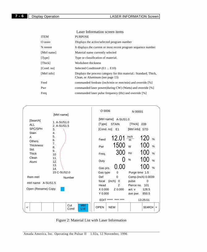
Laser Information screen itemsITEM PURPOSE
O oooo Displays the active/selected program number
N nnnnn It displays the current or most recent program sequence number
[Mtrl name] Material name currently selected
[Type] Type or classification of material.
[Thick] Worksheet thickness
[Cond. no] Selected Condition# (E1 ... E10)
[Mtrl info] Displays the process category for this material.: Standard, Thick,Clean, or Aluminum (see page 13)
Feed commanded feedrate (inch/min or mm/min) and override [%]
Pwr commanded laser power(during CW) (Watts) and override [%]
Freq commanded laser pulse frequency (Hz) and override [%]
OPEN NEW SEARCHCutCond
MtrlList +<
O 0006 N 00001
[Mtrl name]
[Type]
[Cond. no]
[Thick]
[Mtrl info]
[Mtrl name]
Rem mtrl
mtrl name A-SUS1.5
Open (Rename) Copy
[Search]ALLSPC/SPHStainAOthersThIcknessStd.ThickCleanAlumi
Number
A-SUS1.0
STAIN .039
E1 STD
inchm
EDIT ***** **** **** 13:25:01
%
%
%
%
%
12.011500300
00.00
120100100100100
Feed
Pwr
Freq.
Duty
Gas prs.
Gas type 0 Purge time 1.5
Def 0focal (inch) 0Head 2X 0.000 Z 0.000Y 0.000
Comp.(inch) 0.0039pulse 0Pierce no. 101act. v 128.5ave pwr. 850.5
1. A-SUS1.02. A-SUS1.53.4.5.6.7.8.9.1011.12.13.14.15 C-SUS2.0
W
Hz
%
Figure 2: Material List with Laser Information
7 - 6
Amada America, Inc. Operating the Pulsar II 1.02a, 12 November, 1996
Display Operation LASER INFORMATION Screen
Laser Information screen itemsITEM PURPOSE
Duty commanded laser pulsing duty cycle (%) and override [%]
Gas prs. commanded assist gas pressure and override [%](meaningful only with NC gas pressure control)
Gas type Selected assist gas type (1-5)
Purge time It displays purge time when starting assist gas prior to anypiercing operation.
Def. amount Not used
comp. current cutter offset value
Focal Displays a focus position of lens. It is not applicable to themachine without NC focus control (option).
Pulse Not used with Fanuc laser.
Head Only used with Automatic Head Changer (option).
Pierc No. currently selected piercing routine
X, Y, Z machine position in absolute coordinates.
Act. V machine speed
Ave. pwr Not used
7 - 7
Amada America, Inc. Operating the Pulsar II 1.02a, 12 November, 1996
LASER INFORMATION Screen Display Operation
On-Line Adjustments
It is possible to alter the cutting data (speed, power, frequency, duty, and gas pres-sure) while a program is running. This is done using the override knob on theoperation panel.
Cutting gas pressure is controllable from the NC only when the ProgrammableGas Pressure option is present.
� This operation can permanently change the stored cutting data.
SAVE any current cutting data edits before attempting this
Afterwards, do not “save” without verifying the changes you have made.
Data can also be edited using the Fanuc keypad. (see page 16)
Preparation
Select the Cutting Data Screen.
Only the currently selected material and cutting condition can be altered usingthis procedure.
The item to be altered is selected by the buttons above the override knob. (CUT-
TING RATE, POWER, FREQUENCY, DUTY, GAS PRESSURE)
Adjustment step size
The step size for each step of the override knob is controlled by the1/10 button.
Light off: Normal step size
Light on: Changes at 1/10 the normal step size.
7 - 8
Amada America, Inc. Operating the Pulsar II 1.02a, 12 November, 1996
On-Line Adjustments LASER INFORMATION Screen
Adjustments
This changes data for the active material and cutting condition. (shown by greenhighlight on screen)
1) While the program is running, press the “DATA SET” button on the operationpanel. (illuminates when active)
When you activate DATA SET, the Cutting Condition screen is shown if the Mate-rial Table screen, the Pierce Condition screen, or the Edge Condition screen wasactive.The “DATA SET” button disables soft keys and the Fanuc keypad while active.Release it to use the keypad or soft keys. It goes off automatically when the autooperation is over.
2) Press the button of the item you want to change. (illuminates when active)
3) Set by turning the knob while pressing “ENABLE” button.
Clockwise: + direction
Counterclockwise: - direction
� Notes
1. The knob has no effect unless “DATA SET” is active and the “ENABLE” buttonis pressed at the same time as the knob is turned.
2. Only values within the setting range of each item are available.
3. SAVE any desired changes before running any program which performs mate-rial selection by M102 (material name ). Otherwise, a new working copy of thedata is created, and any unsaved changes are discarded.
The above operationis not the same as using the OVERRIDE function, whichonly applies a multiplier to the values commanded in the cutting data file. Thisfunction alters the working copy of the data file.
To store the changed values created by the OVERRIDE function, you must manu-ally input them on each screen of cut or pierce, and then SAVE them.
7 - 9
Amada America, Inc. Operating the Pulsar II 1.02a, 12 November, 1996
LASER INFORMATION Screen On-Line Adjustments
Cutting Data Library
The Cutting Data Library contains data for a variety of material types and thick-nesses. This data is stored in the NC, and can also be transferred to/from floppydisk for various purposes. See page 38 for information on loading and saving cut-ting data.
Overview
Each type/thickness is referred to as a cutting data file. Each cutting data filemust have a unique name (such as CRS063) which is used to select it for editingand operation. Each named material (cutting data file) contains ten sets of cuttingconditions, and various other information about processing the material.
A part-program can select any named material (cutting data file) and any of thecutting conditions within that file. The feedrate, power, and all other parametersfrom that file are then automatically used by the NC until another named materialis selected. A program can switch between material conditions as needed whilerunning.
Each cutting data file in the library is classified by material, worksheet thickness,and process category (clean-cut, thick plate, etc.) and managed by material name.
Ten cutting conditions, three pierce conditions, and five edge conditions arestored in each cutting data file.
Up to 90 material names may be kept in the NC at one time.
You can override speed, output, frequency, duty, and gas pressure (option) whileexecuting the program.
7 - 10
Amada America, Inc. Operating the Pulsar II 1.02a, 12 November, 1996
Overview Cutting Data Library

Example
The program segment in figure 3 shows an example of cutting data use.
The cutting data file “O-CRS063" is selected for use by the M102 (cutting mate-rial select). This copies data from the cutting data file of O-CRS063 into activememory for use.
The command “E1" selects Condition number 1. This determines the feedrate,power, default pulsing parameters, assist gas selection, and cutter offset to be usedwhile cutting.
The default PIERCE NO is set in the cutting data file for all cutting conditions. Tospecify a different pierce number in the program, command E101 - E103.
For no piercing (just “beam ON and proceed”), specify A0 on your M103 com-mand line. (M103 A0;)
The default EDGE and Approach (lead-in) data is set in the cutting data file foreach cutting condition.
To specify an EDGE or Approach number in the program, specify E201 - E203.
O1313 (CUTTING DATA DEMO);
G20;
G92 X49.12 Y49.12 Z9.7;
M100;
M102(O-CRS063);
E1;
G00 X12.5 Y24.8;
.
.
.
Figure 3: Material selection in program
7 - 11
Amada America, Inc. Operating the Pulsar II 1.02a, 12 November, 1996
Cutting Data Library Overview
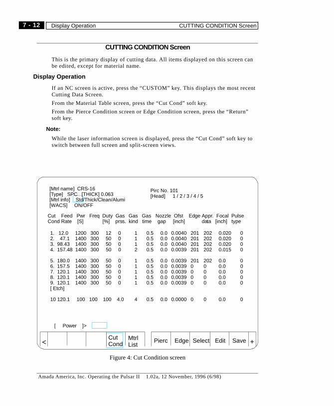
CUTTING CONDITION Screen
This is the primary display of cutting data. Al l items displayed on this screen canbe edited, except for material name.
Displ ay Operation
I f an NC screen is active, press the “CUSTOM” key. This displays the most recentCutting Data Screen.
From the Material Table screen, press the “Cut Cond” soft key.
From the Pierce Condition screen or Edge Condition screen, press the “Return”soft key.
� Note:
While the laser information screen is displayed, press the “Cut Cond” soft key toswitch between ful l screen and split-screen views.
Pierc Edge Select Edit SaveCutCond
MtrlList +<
[Mtrl name] CRS-16[Type] SPC [THICK] 0.063[Mtrl info] Std/Thick/Clean/Alumi[WACS] ON/OFF
Cut Feed Pwr Freq Duty Gas Gas Gas Nozzle Ofst Edge Appr. Focal PulseCond Rate [S] [%] prss. kind time gap [inch] data [inch] type
1. 12.0 1200 300 12 02. 47.1 1400 300 50 03. 98.43 1400 300 50 04. 157.48 1400 300 50 0
5. 180.0 1400 300 50 06. 157.5 1400 300 50 07. 120.1 1400 300 50 08. 120.1 1400 300 50 09. 120.1 1400 300 50 0[ Etch]
10 120.1 100 100 100 4.0
[ Power ]>
0.50.50.50.5
0.50.50.50.50.5
0.5
1112
11111
4
0.00.00.00.0
0.00.00.00.00.0
0.0
0.00400.00400.00400.0039
0.00390.00390.00390.00390.0039
0.0000
0.0200.0200.0200.015
0.00.00.00.00.0
0.0
0000
00000
0
201201201201
2010000
0
202202202202
2020000
0
Pirc No. 101[Head] 1 / 2 / 3 / 4 / 5
Figure 4: Cut Condition screen
7 - 12
Amada America, Inc. Operating the Pulsar II 1.02a, 12 November, 1996 (6/98)
Display Operation CUTTING CONDITION Screen

Items on Cutting Condition screen
This information defines the type and characteristics of the material. It is re-peated on the PIERCE and EDGE screens.
Header information
This information is the same for each cutting condition of a particular cutting datafile. It is repeated on the PIERCE and EDGE screens.
Mtrl name:Displays the currently selected material name (cutting data file).
Type:Displays currently selected material quality selected.It is used for search/management on the Material List screen.Setting range: Eight characters or less.Allowable characters: English letters, “-”, “.”
Thick:Displays material worksheet thickness for Z-axis positioning purposes.Be sure to set it to the correct thickness of the material to be processed.Setting range: 0.00 ~ 999.99Setting unit: mm(inch)
Mtrl info.:
Displays the “process category” for this material. This affects certain behaviors ofthe machine. The selected process category is highlighted in green.
Category Includes
Standard Soft steel plate less than 9.0mm (38
inch), stainless cut with oxygen
Thick Soft steel plate of over 9.0 mm (38
inch and over)
Clean Clean cut™ (stainless, etc)
Alumi Aluminum
WACS(option) Select water nozzle ON or OFF. Only applies to machines with water noz-zle.
Pierce No.It selects default piercing routine for selected material. ( 101 ~ 103 ) See thePierce Condition screen (page 18) for more information.
Head:Only used with optional Automatic Head Changer.
7 - 13
Amada America, Inc. Operating the Pulsar II 1.02a, 12 November, 1996
CUTTING CONDITION Screen Display Operation
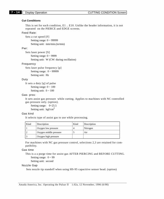
Cut Conditi ons
This is set for each condition, E1 .. E10. Unlike the header information, i t is notrepeated on the PIERCE and EDGE screens.
Feed Rate:Sets a cut speed [F]
Setting range: 0 ~ 99999Setting unit: mm/min.(in/min)
Pwr:Sets laser power [S]
Setting range: 0 ~ 9999Setting unit: W (CW: during oscillation)
FrequencySets laser pulse frequency [p]
Setting range: 0 ~ 99999Setting unit: Hz
DutyI t sets a duty [q] of pulse
Setting range: 0 ~ 100Setting unit: 0 ~ 100
Gas- prss:I t sets assist gas pressure while cutting. Applies to machines with NC controlledgas pressure only. (option).
Setting range: 0~25.5Setting unit: kgf/cm2
Gas kindI t selects type of assist gas to use while processing.
Kind Description Kind Description
1 Oxygen low pressure 4 Nitrogen
2 Oxygen middle pressure 5 Air
3 Oxygen high pressure
For machines with NC gas pressure control, selections 2,3 are retained for com-patibility.
Gas timeThis is a a purge time for assist gas AFTER PIERCING and BEFORE CUTTING.
Setting range: 0 ~ 99Setting unit: second
Nozzle GapSets nozzle tip standoff when using HS-95 capacitive sensor head. (option)
7 - 14
Amada America, Inc. Operating the Pulsar II 1.02a, 12 November, 1996 (6/98)
Display Operation CUTTING CONDITION Screen
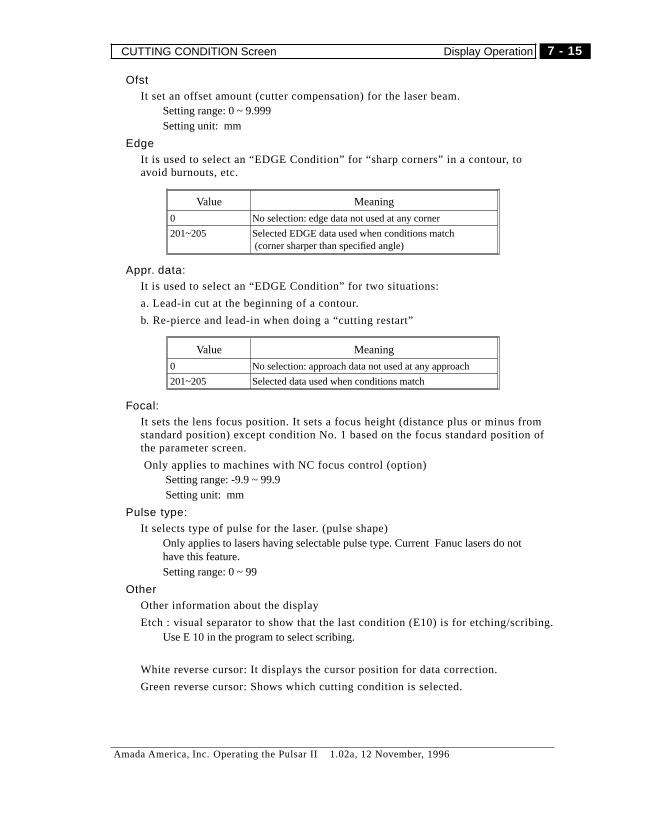
OfstIt set an offset amount (cutter compensation) for the laser beam.
Setting range: 0 ~ 9.999Setting unit: mm
EdgeIt is used to select an “EDGE Condition” for “sharp corners” in a contour, toavoid burnouts, etc.
Value Meaning
0 No selection: edge data not used at any corner
201~205 Selected EDGE data used when conditions match(corner sharper than specified angle)
Appr. data:It is used to select an “EDGE Condition” for two situations:
a. Lead-in cut at the beginning of a contour.
b. Re-pierce and lead-in when doing a “cutting restart”
Value Meaning
0 No selection: approach data not used at any approach
201~205 Selected data used when conditions match
Focal:It sets the lens focus position. It sets a focus height (distance plus or minus fromstandard position) except condition No. 1 based on the focus standard position ofthe parameter screen.
Only applies to machines with NC focus control (option)Setting range: -9.9 ~ 99.9Setting unit: mm
Pulse type:It selects type of pulse for the laser. (pulse shape)
Only applies to lasers having selectable pulse type. Current Fanuc lasers do nothave this feature.Setting range: 0 ~ 99
OtherOther information about the display
Etch : visual separator to show that the last condition (E10) is for etching/scribing.Use E 10 in the program to select scribing.
White reverse cursor: It displays the cursor position for data correction.
Green reverse cursor: Shows which cutting condition is selected.
7 - 15
Amada America, Inc. Operating the Pulsar II 1.02a, 12 November, 1996
CUTTING CONDITION Screen Display Operation

Editing Cut Conditions
You can edit cutting, piercing, and edge data anytime. (the system is always in ma-terial edit mode.)
The PROGRAM PROTECT key does not protect against cutting data editing.
The Cursor keys (ßàáâ) are used to select data items on the screen. A white re-verse cursor shows where you are.
If you press “Cursor key UP” at condition No.1, the cursor moves to “Type”.
If you press “cursor key DOWN” at condition No. 10, the cursor moves to condi-tion No. 1.
Selection of cut condition
A cutting condition can be selected manually for test or operation. Manual selec-tions are superseded by selections within a running part-program, though.
Selection by means of cursor
1) Press soft key SELECT (begins Selection Mode)2) Use the cursor keys (“áâ”) to move the white reverse cursor to the desired condi-
tion.3) Press INPUT key (Selects that condition, as shown by the green full-width high-
light bar. Returns to Correction Mode)
Selection by means of key input
1) Press the SELECT soft key (activates Selection Mode).2) A white reverse cursor is displayed: Key in the desired cutting condition No.3) Press INPUT (returns to Correction Mode)
� NOTES
To return to Correction Mode without selecting a new condition, press the EDITsoft key.
When a program is run, any material selection command will supersede manualselection. Any E-code in that program will supersede the manually selectedvalue.
Batch conversion of data
To change data below the cursor position to match the data at the cursor position.1. Move the cursor to an item you want to perform batch conversion with “Cursor key”
2. Press the soft key.3. Press the “All Repla.” soft key.4. Data below the cursor position to No. 9 changes to the same data as the cursor posi-
tion. However, [Etch] data (No 10) does not change.
+
7 - 16
Amada America, Inc. Operating the Pulsar II 1.02a, 12 November, 1996
Editing Cut Conditions CUTTING CONDITION Screen
Editing Data
1) Move the cursor to the data you want to correct by pressing the cursor keys(ßàáâ)
2) Key in the desired value .3) Press “INPUT” or any of the Cursor keys (ßàáâ)
� Notes
If a value input is outside the valid range, “Data error” message is displayedand the cursor does not move.
Press the CAN key to remove erroneous characters from the input key buffer.
Data storage
To save changes in cutting, edge, or piercing data.1) Press soft key Save2) Storage is completed with a message “Has been saved”
� WARNINGEdited data remains on the screen, but the original data does not change until
you SAVE the new data.Any unsaved changes are lost when:(1) a different material is selected manually(2) ANY material is selected by part-program using M102().
7 - 17
Amada America, Inc. Operating the Pulsar II 1.02a, 12 November, 1996
CUTTING CONDITION Screen Editing Cut Conditions
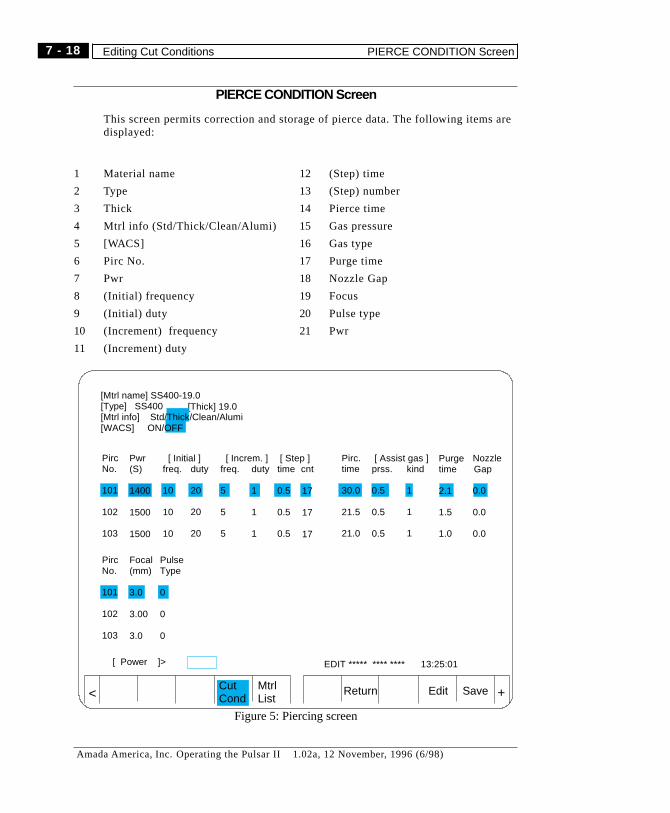
PIERCE CONDITION Screen
This screen permits correction and storage of pierce data. The foll owing items aredisplayed:
PircNo.
101
102
103
[Thick] 19.0
EDIT ***** **** **** 13:25:01
Return Edit SaveCutCond
MtrlList +<
[Mtrl name] SS400-19.0[Type] SS400[Mtrl info] Std/Thick/Clean/Alumi[WACS] ON/OFF
[ Power ]>
Pwr(S)
1400
1500
1500
Pirc.time
30.0
21.5
21.0
[ Assist gas ]prss.
0.5
0.5
0.5
kind
1
1
1
[ Initial ]freq.
10
10
10
duty
20
20
20
[ Increm. ]freq.
5
5
5
duty
1
1
1
Purgetime Gap
2.1
1.5
1.0
[ Step ]time
0.5
0.5
0.5
Nozzle
0.0
0.0
0.0
cnt
17
17
17
PircNo.
101
102
103
Focal(mm)
3.0
3.00
3.0
PulseType
0
0
0
Figure 5: Piercing screen
1 Material name
2 Type
3 Thick
4 Mtr l info (Std/Thick/Clean/Alumi)
5 [WACS]
6 Pirc No.
7 Pwr
8 (Initial ) frequency
9 (Initial ) duty
10 (Increment) frequency
11 (Increment) duty
12 (Step) time
13 (Step) number
14 Pierce time
15 Gas pressure
16 Gas type
17 Purge time
18 Nozzle Gap
19 Focus
20 Pulse type
21 Pwr
7 - 18
Amada America, Inc. Operating the Pulsar II 1.02a, 12 November, 1996 (6/98)
Editing Cut Conditions PIERCE CONDITION Screen

Display Operation
1) If an NC screen is active, press the CUSTOM key to display the Cutting DataScreens.
The most recent Cutting Data Screen is displayed again.
2) Press the “Cut cond” soft key on the material table screen. (The cutting condi-tion screen is displayed).
Press the “Pierce” soft key on the cutting condition screen. (The pierce conditionscreen is displayed).
Press soft key “Return” soft key on the edge condition screen. (The cut conditionscreen is displayed).
� Note
While the laser information screen is being displayed, it is switched to a fullscreen if you press the “Cut Cond ” soft key. If you press the “Cut Cond” soft keyagain, it displays the laser information screen.
Display items
Header Information
This is information about the material. It is the same as shown on the Cutting Con-dition screen. (Mtrl name, Thick, Mtrl info, [WACS])
See page 13 for description of header information.
Piercing Data Table
The following items may be set for each pierce condition (101~103)
pwrIt sets Laser power [S]
Setting range: 0 ~9999Setting unit : Watts (CW : during oscillation)
freq [Initial value]It sets a frequency [P] of pulse
It sets a initial value of frequency if it is a high speed pierce for Thick..Setting range: 0 ~ 9999Setting unit: Hz
duty:It sets a duty [Q] of pulse
It sets an initial value of duty (only for high speed pierce of thick worksheet).Setting range: 0 ~ 100Setting unit: %
7 - 19
Amada America, Inc. Operating the Pulsar II 1.02a, 12 November, 1996
PIERCE CONDITION Screen Display Operation
freq [Increment value]It sets an increment value of frequency. (only for high speed pierce of thick work-sheet).
Set it 0 if it is not a high speed pierceSetting range: 0 ~ 9999Setting unit: Hz
Step time:It sets step time for increase of frequency and duty. (Only for high speed pierce ofthick worksheet).
Set it 0 if it is not a high speed pierceSetting range: 0 ~ 9.9Setting unit: second
Step number:It sets step number for increase of frequency and duty. (Only for high speed pierceof thick worksheet).
Set if 0 if it is not a high speed pierce.Setting range: 0 ~ 9.9Setting unit: times
Pierce time:It sets pierce time (second)
Setting range: 0.1 ~ 99.9Setting unit: second
Gas pressure:It sets pressure of assist gas. It is not applicable to the machine without gas pres-sure NC control (option).
Setting range: 0~25.5Setting unit: kgf/cm2
Gas type:It selects assist gas type for piercing. See page 14 for a listing of gas types.
purge time:It sets a purge time of assist gas. When it is switched to assist gas for cut, it waitsfor a period time set.
Setting range: 0 ~ 99Setting unit: second
Def. amount:not used.
7 - 20
Amada America, Inc. Operating the Pulsar II 1.02a, 12 November, 1996
Display Operation PIERCE CONDITION Screen
Focus:It sets a focus position of lens. Applies only to machines with NC focus control(option).
Setting range: -9.9 ~ 99.9Setting unit: mm (inch)
Pulse type:It sets a type of pulse.
It is not applicable to a machine w/o “pulse type”.Setting range: 0 ~ 99
White reverse cursor: It displays the cursor position of data correction.
Green reverse cursor: It displays cut condition selected.
Setting Operation
Editing procedures are the same as for the Cutting Condition screen. You can editcutting, piercing, and edge data anytime. (the system is always in material editmode.)
The PROGRAM PROTECT key does not protect against cutting data editing.
Editing Data
1) Move the cursor to the data you want to correct with the cursor keys “ßàáâ”2) Correct it to a value desired with the Alphanumeric keys.3) Press “INPUT” or one of the cursor keys “ßàáâ”
� If a value input is outside the valid numeric range, a “Data error” message isdisplayed and the cursor does not move.
Press the CAN key to remove erroneous characters from the input key buffer.
� Note
If you press “Cursor key UP” at the pierce No.1, the cursor moves to “Type”.
If you press “Cursor key DOWN” at the pierce No. 3, the cursor moves to pierceNo. 1.
7 - 21
Amada America, Inc. Operating the Pulsar II 1.02a, 12 November, 1996
PIERCE CONDITION Screen Setting Operation

Batch Conversion of Data
Data below the cursor position changes to the same data as the cursor position.1. Use the cursor keys to move the cursor to an item you want to perform batchconversion .
2. Press the soft key.3. Press the “All Repla.” soft key.4. Data below the cursor position changes to the same data as the cursor position.
Data storage
To save changes for future use.1) Press theSavesoft key .2) Storage is completed with a message “Saved”
� Caution
The revised data is displayed on the screen, but until changes are Saved, the origi-nal data (in storage) does not change. Any operation which calls up a material file(either the same one or a different one) causes the revised data to be lost. This es-pecially includes M102 ( ). The revised data is replaced by the data called fromstorage.
+
7 - 22
Amada America, Inc. Operating the Pulsar II 1.02a, 12 November, 1996
Setting Operation PIERCE CONDITION Screen

Notes
7 - 23
Amada America, Inc. Operating the Pulsar II 1.02a, 12 November, 1996
PIERCE CONDITION Screen Setting Operation
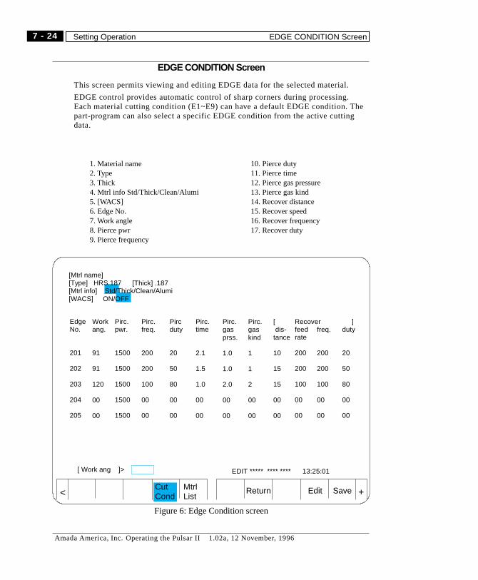
EDGE CONDITION Screen
This screen permits viewing and editing EDGE data for the selected material.
EDGE control provides automatic control of sharp corners during processing.Each material cutting condition (E1~E9) can have a default EDGE condition. Thepart-program can also select a specific EDGE condition from the active cuttingdata.
1. Material name2. Type3. Thick4. Mtrl info Std/Thick/Clean/Alumi5. [WACS]6. Edge No.7. Work angle8. Pierce pwr9. Pierce frequency
10. Pierce duty11. Pierce time12. Pierce gas pressure13. Pierce gas kind14. Recover distance15. Recover speed16. Recover frequency17. Recover duty
EdgeNo.
201
202
203
204
205
[Thick] .187
EDIT ***** **** **** 13:25:01
Return Edit SaveCutCond
MtrlList +<
[Mtrl name][Type] HRS.187[Mtrl info] Std/Thick/Clean/Alumi[WACS] ON/OFF
[ Work ang ]>
Workang.
91
91
120
00
00
Pirc.pwr.
1500
1500
1500
1500
1500
Recoverfeedrate
200
200
100
00
00
]duty
20
50
80
00
00
Pirc.time
2.1
1.5
1.0
00
00
Pirc.gasprss.
1.0
1.0
2.0
00
00
Pirc.gaskind
1
1
2
00
00
[dis-
tance
10
15
15
00
00
Pirc.freq.
200
200
100
00
00
Pircduty
20
50
80
00
00
freq.
200
200
100
00
00
Figure 6: Edge Condition screen
7 - 24
Amada America, Inc. Operating the Pulsar II 1.02a, 12 November, 1996
Setting Operation EDGE CONDITION Screen
Display Operation
1) If an NC screen is active, press the “CUSTOM” key.
The most recent Cutting Data Screen is displayed again.
2) From the material table screen, press the “Cut Cond” soft key.
From the pierce condition screen, press the “Return ” soft key.
3) Press theEDGE soft key to show the edge condition screen.
� Note:
Press the “Cut Cond” soft key to switch between full screen and split-screenviews.
Display items
This screen displays the material header information (same as Cutting Conditionand EDGE Condition screens) and the piercing data table.
Header Information
This is information about the material. It is the same as shown on the Cutting Con-dition screen. (Mtrl name, Thick, Mtrl info, [WACS])
See page 13 for description of header information.
EDGE Data Table
The following items may be set for each Edge condition (201~205).
Note that “edge end point” refers to the point at the corner detected as being“sharp”. (see following)
Work AngIt sets an angle to switch from active cutting condition to specified edge condition.
Setting range: 0° < angle < 180°Setting unit : degree(see page 28 for illustration)
Pierce pwrSets laser power [S] when piercing at the edge end point.
Setting range: 0 ~ 9999Setting unit: W
7 - 25
Amada America, Inc. Operating the Pulsar II 1.02a, 12 November, 1996
EDGE CONDITION Screen Display Operation

Pierce freqIt sets a frequency of pulse [P] when piercing at the edge end point.
Setting range: 0 ~ 9999Setting unit: Hz
Pierce dutyIt sets a duty of pulse [Q] when piercing at the edge end point
Setting range: 0 ~ 100Setting unit: 0/0
Pierce timeIt sets pierce time (second) when piercing at the edge end position
Setting range: 0 ~ 99.9Setting unit: second
Pierce gas pressure:It sets assist gas pressure when piercing at the edge end point.
It is not applicable to a machine without gas pressure NC control.Setting range: 0~25.5Setting unit: kgf/cm2
Pierce gas type:It sets an assist gas type when piercing at the edge end point
See page 14 for a listing of gas types.
Recover distance:It determines the distance that Recover speed, Recover frequency, and Recoverduty are used.
Setting range: 0 ~ 99.999Setting unit: mm (inch)
Recover speed:It sets speed [F] during recovery from the edge end point.
It also sets speed for approach cutSetting range: 0 ~ 9999Setting range: mm/min.
Recover frequency:It sets laser pulse frequency during recovery from the edge end point.
It also is used during approach cuts.Setting range: 0 ~ 9999Setting unit: Hz
Recover duty:It sets a laser pulse duty during recovery from the edge end point.
It also sets a duty for approach cut.Setting range: 0 ~ 100Setting unit: %
7 - 26
Amada America, Inc. Operating the Pulsar II 1.02a, 12 November, 1996
Display Operation EDGE CONDITION Screen
Editing EDGE conditions
Editing procedures are the same as for the Cutting Condition screen. You can editcutting, piercing, and edge data anytime. (the system is always in material editmode.)
� The PROGRAM PROTECT key does not protect against cutting data editing.
Navigation
If you press “Cursor key UP” at the edge No.1, the cursor moves to “type”.
If you press “Cursor key DOWN” at the edge No. 5, the cursor moves to conditionNo. 1.
The White indicates cursor position for editing.
A Green shows which edge condition is selected.
Editing
1) Move the cursor to the data you want to correct with the cursor keys “ßàáâ”
2) Key in the desired value .
3) Press the INPUT key or any of the cursor keys “ßàáâ”.
� Notes
If the value corrected is outside the valid range, a “Data error” message isdisplayed and the cursor does not move.
Batch conversion of data
Data below the cursor position changes to the same value as at the cursor position.1. Use the cursor keys “ßàáâ” to place the cursor at the source item.
2. Press the soft key.3. Press the “All Repla.” soft key.4. Data below the cursor position changes to the same data as the cursor position.
Data storage
The Save soft key is used to save changes. It saves ALL changes made to Cutting,Piercing, and Edge data.
1) Press theSavesoft key.2) Storage is completed with a message “has been saved”
� Caution
The revised data is displayed on the screen, but until changes are Saved, the origi-nal data (in storage) does not change. Any operation which calls up a material file(either the same one or a different one) causes the revised data to be lost. This es-pecially includes M102 ( ). The revised data is replaced by the data called fromstorage.
reverse cursor
reverse cursor
+
7 - 27
Amada America, Inc. Operating the Pulsar II 1.02a, 12 November, 1996
EDGE CONDITION Screen Editing EDGE conditions
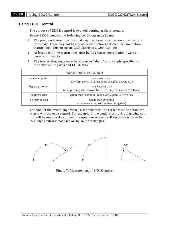
Using EDGE Control
The purpose of EDGE control is to avoid burning at sharp corners.
To use EDGE control, the following conditions must be met.
1 The program instructions that make up the corner must be two move instruc-tions only. There may not be any other instructions between the two motioninstructions. This means no EOB characters, G00, G09, etc.
2 At least one of the instructions must be G01 linear interpolation. (Curve-curve won’t work)
3 The intersecting angle must be at least as “sharp” as the angle specified inthe active cutting data and EDGE data.
Start and stop at EDGE point
at corner point use Pierce data(perform pierce at corner using specified power, etc.)
departing corner use Recover data(after piercing, use Recover feed, freq, duty for specified distance)
no pierce data ignore stop condition- immediately go to Recover data
no recover data ignore start condition(continue cutting with active cutting data)
The smaller the “Work ang” value is, the “sharper” the corner must be before thesystem will use edge control. For example: if the angle is set to 91, then edge con-trol will be used on the corners of a square or rectangle. If the value is set to 89,then edge control is not used on square or rectangles.
Figure 7: Measurement of EDGE angles
7 - 28
Amada America, Inc. Operating the Pulsar II 1.02a, 12 November, 1996
Using EDGE Control EDGE CONDITION Screen

Approach Control
The purpose of approach control is to avoid burning at lead-ins.
Approach control is used whenever the active cutting data (selected by M102(mtrl) and E-code ) includes a value for “Appr. data”. When approach control is ac-tive, the first portion of the cut is performed using data from the [Recover] sectionof the EDGE table. This occurs only after a pierce, regradless of whether it is inthe program (in M103 mode, etc.) or in a Standard Hole macro (G112, etc.).
The “Pirc.” data is not used in Approach control, only for edge control.
EdgeNo.
201
[Thick] .187[Mtrl name][Type] HRS.187[Mtrl info] Std/Thick/Clean/Alumi[WACS] ON/OFF
Workang.
91
Pirc.pwr.
1500
Recoverfeedrate
200
]duty
20
Pirc.time
2.1
Pirc.gasprss.
1.0
Pirc.gaskind
1
[dis-
tance
10
Pirc.freq.
200
Pircduty
20
freq.
200
used at corner point (“edge endpoint”) for re-pierce
used when departing “edge endpoint” and for approach control.
Figure 8: Edge screen
[Mtrl name] CRS-16[Type] SPC [THICK] 0.063[Mtrl info] Std/Thick/Clean/Alumi[WACS] ON/OFF
Cut Feed Pwr Freq Duty Gas Gas Gas Def. Ofst Edge Appr. Focal PulseCond Rate [S] [%] prss. kind time [inch] data [inch] type
1. 12.0 1200 300 12 02. 47.1 1400 300 50 03. 98.43 1400 300 50 0
0.50.50.5
111
0.00.00.0
0.00400.00400.0040
0.0200.0200.020
000
201201201
202202202
Pirc No. 101[Head] 1 / 2 / 3 / 4 / 5
specify handling of sharpcorners
specify handling ofapproach
Figure 9: EDGE setup
7 - 29
Amada America, Inc. Operating the Pulsar II 1.02a, 12 November, 1996
EDGE CONDITION Screen Using EDGE Control
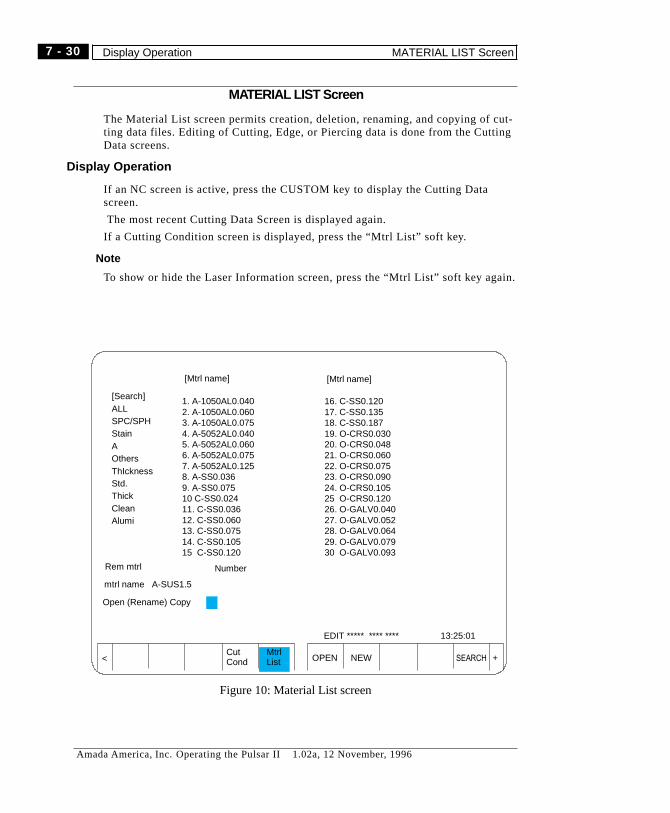
MATERIAL LIST Screen
The Material List screen permits creation, deletion, renaming, and copying of cut-ting data files. Editing of Cutting, Edge, or Piercing data is done from the CuttingData screens.
Display Operation
If an NC screen is active, press the CUSTOM key to display the Cutting Datascreen.
The most recent Cutting Data Screen is displayed again.
If a Cutting Condition screen is displayed, press the “Mtrl List” soft key.
� Note
To show or hide the Laser Information screen, press the “Mtrl List” soft key again.
OPEN NEW SEARCHCutCond
MtrlList +<
[Mtrl name]
Rem mtrl
mtrl name A-SUS1.5
Open (Rename) Copy
[Search]ALLSPC/SPHStainAOthersThIcknessStd.ThickCleanAlumi
Number
EDIT ***** **** **** 13:25:01
1. A-1050AL0.0402. A-1050AL0.0603. A-1050AL0.0754. A-5052AL0.0405. A-5052AL0.0606. A-5052AL0.0757. A-5052AL0.1258. A-SS0.0369. A-SS0.07510 C-SS0.02411. C-SS0.03612. C-SS0.06013. C-SS0.07514. C-SS0.10515 C-SS0.120
16. C-SS0.12017. C-SS0.13518. C-SS0.18719. O-CRS0.03020. O-CRS0.04821. O-CRS0.06022. O-CRS0.07523. O-CRS0.09024. O-CRS0.10525 O-CRS0.12026. O-GALV0.04027. O-GALV0.05228. O-GALV0.06429. O-GALV0.07930 O-GALV0.093
[Mtrl name]
Figure 10: Material List screen
7 - 30
Amada America, Inc. Operating the Pulsar II 1.02a, 12 November, 1996
Display Operation MATERIAL LIST Screen
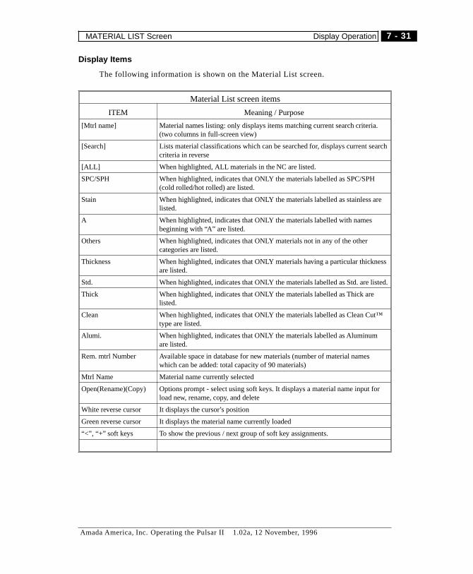
Display Items
The following information is shown on the Material List screen.
Material List screen items
ITEM Meaning / Purpose
[Mtrl name] Material names listing: only displays items matching current search criteria.(two columns in full-screen view)
[Search] Lists material classifications which can be searched for, displays current searchcriteria in reverse
[ALL] When highlighted, ALL materials in the NC are listed.
SPC/SPH When highlighted, indicates that ONLY the materials labelled as SPC/SPH(cold rolled/hot rolled) are listed.
Stain When highlighted, indicates that ONLY the materials labelled as stainless arelisted.
A When highlighted, indicates that ONLY the materials labelled with namesbeginning with “A” are listed.
Others When highlighted, indicates that ONLY materials not in any of the othercategories are listed.
Thickness When highlighted, indicates that ONLY materials having a particular thicknessare listed.
Std. When highlighted, indicates that ONLY the materials labelled as Std. are listed.
Thick When highlighted, indicates that ONLY the materials labelled as Thick arelisted.
Clean When highlighted, indicates that ONLY the materials labelled as Clean Cut™type are listed.
Alumi. When highlighted, indicates that ONLY the materials labelled as Aluminumare listed.
Rem. mtrl Number Available space in database for new materials (number of material nameswhich can be added: total capacity of 90 materials)
Mtrl Name Material name currently selected
Open(Rename)(Copy) Options prompt - select using soft keys. It displays a material name input forload new, rename, copy, and delete
White reverse cursor It displays the cursor’s position
Green reverse cursor It displays the material name currently loaded
“<”, “+” soft keys To show the previous / next group of soft key assignments.
7 - 31
Amada America, Inc. Operating the Pulsar II 1.02a, 12 November, 1996
MATERIAL LIST Screen Display Operation
Cutting Data File Operations
Material files can be created, deleted, and renamed. When creating a new file, youcan copy from an existing file or start with a “clean sheet”.
The cursor keys (“ßàáâ”) on the Fanuc keypad are used to select items on thescreen. Item selection is indicated by a white highlight on the selected item.
Data Input
When a new name is required, use the Fanuc keypad and key-in the material nameto load.
� Press the CAN key to remove erroneous characters from the input key buffer.
Press the INPUT key to activate that material data file.
Name limitations
Length: up to 15 characters
Usable Characters: Alpha-numerics, “-”, “.”
Selecting a material
You can use the cursor keys to select a material, or just key the name in, using theFanuc keypad.
Selection
1) Move the white highlight (cursor) to a material name you want to load with thecursor keys ( “ßàáâ”).2) Press the INPUT key -2) Execute by pressing the “Open” soft key.
� CautionWhen a specified material name already exists in the NC, a message “The
material name already exists” is displayed. No two Cutting Data files canhave the same name.
When a specified material name does not exist, a message “The material namedoes not exist” is displayed.
You cannot load during AUTO operation.
7 - 32
Amada America, Inc. Operating the Pulsar II 1.02a, 12 November, 1996
Cutting Data File Operations MATERIAL LIST Screen
Creating New Material Name .
This creates a new, blank Cutting Data file.
1) Key in the name you want use for the new material file.Setting range: less than 16 charactersCharacter restriction: Alphanumerics, “-”, “.”
2) Press the INPUT key
3) Press the “NEW” soft key to create the material data file. The display ischanged to the cutting condition screen
4) Press the “Save” soft key to store the new file in memory. Once you set andSave the cut condition on the cutting condition screen, the “new” registration isover.
� WARNINGYou must “Save” the new file, as it is created in temporary storage only. Use
the “Save” soft key on the cutting condition screen to store the new data file.
If the specified material name already exists, a message “The material name al-ready exists” is displayed, and the “new” operation fails.
Material names can’t be newly created during auto operation. If attempted, themessage “It cannot be used during operation” is displayed.
Rename a material
This is to change the name of an existing material (cutting data file).
1) Load the material name you want to rename
� If it is already loaded, you don’t have to load it again.
2) Input the new material name.Use the Fanuc keypad “Address/numeric” keysSetting range: less than 16 charactersCharacter restriction: Alphanumerics, “-”, “.”
3) Press the INPUT key
4) Press the “Rename” soft key to execute.
� NotesIf the “new” name is already in use, a message “The material name already
exists” is output and the rename operation fails.Renaming is not permitted during machine operation. A message “It cannot be
used during operation” is output and the material name is not changed
7 - 33
Amada America, Inc. Operating the Pulsar II 1.02a, 12 November, 1996
MATERIAL LIST Screen Cutting Data File Operations
Copy to new file
Creates a new material file using data from an existing material file.
1) Load the material file to copy.
2) Input a new material name with “Address/numeric key”
Setting range: less than 16 characters
Character restriction: English numerals
3) Confirm the new material name by pressing the “INPUT” key.
4) Press the “Copy” soft key to create the new file as a copy of the original file.
� NOTES
If it is already loaded, you don’t have to load it again.Press the CAN key to remove erroneous characters from the input key buffer.If a material name designated exists, a message “The material name already
exists” is output. Select a name that is not already used.Data files can’t be copied during program execution.
Deleting a material name
This deletes the name (and associated information) of a material.
Select the data file to delete.
Press the “Delete” soft key to erase the material name and cutting data from thedatabase.
Even if you delete a material name, the number will stay in the table until sort-ing. When the file is sorted, empty numbers are removed. You can sort when youdesignate “ALL” in the search of the material name.
� Press the CAN key to remove erroneous characters from the input key buffer.
7 - 34
Amada America, Inc. Operating the Pulsar II 1.02a, 12 November, 1996
Cutting Data File Operations MATERIAL LIST Screen
Search of material name
This permits the display of only the materials meeting certain criteria.
1) Press the “Search” soft key. The soft keys then show the following legends:LEGEND: PURPOSE:SPC, SPH: Display all material names whose type is “SPC” or “SPH”.SUS: Display all material names whose type is SUS.A: Display all material names whose type starts with A.Others: Display material names whose type is other than the above.Thick: Display a material name of a designated worksheet thickness.Standard: Display all material names whose process category is “Std.”.Thick.: Display all material names whose process category is “ThickClean: Display all material names whose process category is “Clean”.Alumi: Display all material names whose process category is aluminum.All: Displays ALL material names in memory, Permits sorting names.< returns soft key assignments to previous
2) Select a search condition by pressing the appropriate soft key.
Listing by thickness
Press the “Thick” soft key. Then key the numeric value in, press INPUT. Any mate-rial names having the designated thickness will be listed. If none match, amessage is displayed “There are no data”.
While designating worksheet thickness, to return to the previous screen , press the“<” soft key twice.
� Notes
Each search is through all data in the NC. Therefore, a complex search such as“Thick 2.0 mm” and SUS cannot be performed.
Even if you delete a material name, its No. stays in the table until sorting.
When you sort, empty numbers are removed.
Sorting Names
Press the Search soft key. Then, press the ALL soft key. When you press “All” amessage “Sort? Y/N” is displayed.
Y: It alphabetically sorts material names and displays them.N: It displays them without sorting.
7 - 35
Amada America, Inc. Operating the Pulsar II 1.02a, 12 November, 1996
MATERIAL LIST Screen Cutting Data File Operations
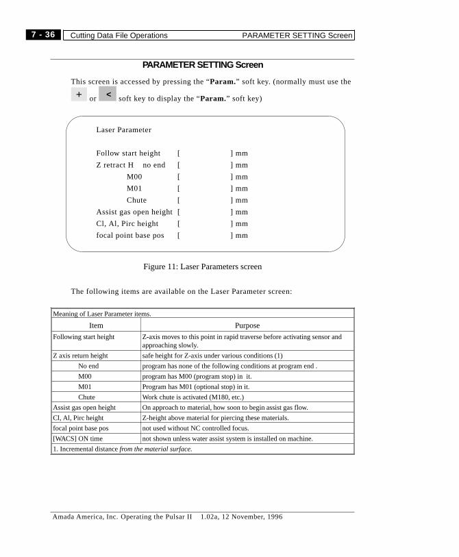
PARAMETER SETTING Screen
This screen is accessed by pressing the “Param.” soft key. (normally must use the
or soft key to display the “Param.” soft key)
The following items are available on the Laser Parameter screen:
Meaning of Laser Parameter items.
Item Purpose
Following start height Z-axis moves to this point in rapid traverse before activating sensor andapproaching slowly.
Z axis return height safe height for Z-axis under various conditions (1)
No end program has none of the following conditions at program end .
M00 program has M00 (program stop) in it.
M01 Program has M01 (optional stop) in it.
Chute Work chute is activated (M180, etc.)
Assist gas open height On approach to material, how soon to begin assist gas flow.
Cl, Al, Pirc height Z-height above material for piercing these materials.
focal point base pos not used without NC controlled focus.
[WACS] ON time not shown unless water assist system is installed on machine.
1. Incremental distancefrom the material surface.
+ <
Laser Parameter
Follow start height [ ] mm
Z retract H no end [ ] mm
M00 [ ] mm
M01 [ ] mm
Chute [ ] mm
Assist gas open height [ ] mm
Cl, Al, Pirc height [ ] mm
focal point base pos [ ] mm
Figure 11: Laser Parameters screen
7 - 36
Amada America, Inc. Operating the Pulsar II 1.02a, 12 November, 1996
Cutting Data File Operations PARAMETER SETTING Screen
� NOTE
When worksheet thickness + Z axis return height + offset Z (G93 Z_ ) is largerthan the Z axis maximum travel range, an alarm will occur during programexecution.
Cl, Al pierce height:To raise the nozzle when piercing with clean cut and aluminum cut.
� NOTE
This sets an incremental distance from the cutting nozzle gap (0.3mm / 0.012inch).
focal point base posOnly applies to machines with (optional) NC focus control.
It sets the standard position of focus (focus lens). The focus moves to the positionwhere the focus of cut condition No. 1 is added to the focus standard positionwhen instructing M100 in the machine with NC focus control (option).
Setting Operation
1 Move the White to the setting position.
2 Key-in the new value.
3 Press the “INPUT” key.
� Notes
Press the CAN key to remove erroneous characters from the input key buffer.Values of “0" or ”minus" are accepted, but will cause problems in operations.
MACHINE ALARMS Screen
It displays machine alarms. See the ALARMS chapter for alarms listing and de-scriptions.
Display Operation
1) Press “HELP” key to toggle between the Alarms page and any other CuttingCondition screen.2) The EXIT soft key displays the most recent Cutting Condition screen.
reverse cursor
7 - 37
Amada America, Inc. Operating the Pulsar II 1.02a, 12 November, 1996
MACHINE ALARMS Screen Setting Operation

CUTTINGDATATRANSFER
The cutting data library, under certain circumstances, can be transferred betweenthe NC and floppy disk. Data contained within the Cutting Data Library is AmadaProprietary information, and must not be disclosed or made available to competi-tors or non-Amada customers.
For this reason and others, the procedures for transfer of cutting data are in a sepa-rate document. Contact Amada if you feel that you need this information.
7 - 38
Amada America, Inc. Operating the Pulsar II 1.02a, 12 November, 1996
Setting Operation CUTTING DATA TRANSFER

Chapter 8
MAINTENANCE
Amada America, Inc. Operating the Pulsar II 1.02a, 12 November, 1996

Daily Maintenance
The following operations should be performed daily.
Cleaning
Cutting head, lens, and nozzle should be cleaned and/or inspected. See page 10 forprocedures.
Check the machine table and material supports for condition.
Noise
Make sure that the drive system (servomotors, etc.) doesn’t make any unusualnoises.
Chiller
Check coolant level in the sight glass. Check coolant flow when the system is run-ning.
Laser Gas Supply
Check pressure in laser gas cylinder. Change cylinder when pressure drops to 145psi.
Assist Gas Supply
Check assist gas supply pressure (for compressed gases) or liquid level (for liquidOxygen , etc.)
8 - 2
Amada America, Inc. Operating the Pulsar II 1.02a, 12 November, 1996
Daily Maintenance

Air System
Minimum inlet pressure is 5.7 kgf/cm2 (85 psi). Check that regulated pressure is 5kgf/cm2 (75 psi), and adjust regulator if necessary. Drain any trapped water fromthe air filter. Check lubricator oil level, and refill it if necessary. (release air pres-sure from the system before attempting refill)
Air Filter
When water collects in the the air filter trap, open the drain cock at the bottom ofthe reservoir to drain it.
Regulator
Set the main air pressure to 5 kgf/cm2 by turning the adjustment knob of the regu-lator.
Lubricator
Make sure that the lubricator (air lubricator) has enough oil in it.
Ü Designated oil for lubricator.
Amada pure oil - A.32 (or its equivalent)
Water drain
2. Regulator
3. Lubricator
Lubricator adjustmentscrew
Mistseparator
1. Air filter,water trap
Figure 1: Air, Gas Panel
8 - 3
Amada America, Inc. Operating the Pulsar II 1.02a, 12 November, 1996
Daily Maintenance
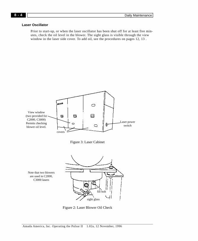
Laser Oscillator
Prior to start-up, or when the laser oscillator has been shut off for at least five min-utes, check the oil level in the blower. The sight glass is visible through the viewwindow in the laser side cover. To add oil, see the procedures on pages 12, 13 .
sight glass
fill bolt
Note that two blowersare used in C2000,
C3000 lasers
Figure 2: Laser Blower Oil Check
Laser powerswitch
View window(two provided forC2000, C3000)
Permits checkingblower oil level.
covers
Figure 3: Laser Cabinet
8 - 4
Amada America, Inc. Operating the Pulsar II 1.02a, 12 November, 1996
Daily Maintenance
Periodic Maintenance
In addition to Daily Maintenance, two maintenance schedules must be followed.The first is according to calendar intervals, and the second is according to runtime. When the same item is listed on both schedules, use the schedule occurringfirst.
Schedule 1
These items are scheduled by calendar periods.
Weekly Maintenance
See lubrication chart for required lubrication items. (page 7)
Inspect the ballscrews for X, Y, and Z-axes. Use compressed air to clean them, andoil lightly.
Grease X, Y-axis ball nuts. (see pages 7, 9 )
Ü Important: Pump enough grease into the fitting so that grease exits fromboth ends of the ball screw nut. This will ensure that the job is
done properly.
Ü Warning: Turn off the circuit breaker for five minutes prior to removing thelaser cover for the following operations.
Check level and appearance of oil in laser vacuum pump. The level should be be-tween the Max. and Min. lines on the sight glass. If the oil is darkened, rather thanclear, it should be changed. See page 13 for oil change, fill procedures. Also,check for signs of oil leakage. Leakage can indicate that the exhaust filter needschanging. (contact Amada)
Monthly Maintenance
See lubrication chart for required lubrication items.(page 7 )
Inspect the Z-axis bend mirror, clean if necessary. (see page 11 for procedure)
Check the coolant flow rate and pressure drop. Change the coolant filter (atchiller) if flow drops or pressure drop is excessive.
Grease fittings on machine. (see pages 7, 9 )
Every Four Months
Change laser blower oil. (see page 12)
Every Six Months
Inspect main air inlet filter, change if necessary.
Change laser vacuum pump oil (see page 13 )
The following items should be performed by Amada service personnel:Change laser vacuum pump exhaust filter.Clean laser internal mirrors.
8 - 5
Amada America, Inc. Operating the Pulsar I I 1.02a, 12 November, 1996 (7/99)
Periodic Maintenance Schedule 1
Every twelve Months
Change the NC memory back-up battery. (NC power must be ON- see page 15)
Fanuc external optics - service or replace
Fanuc internal optics - service or replace
Vacuum pump exhaust filter - replace
Every 24 Months
Fanuc laser: replace pressure controller gas filter
Fanuc laser: replace discharge tube O-rings.
Every 36 Months
Fanuc laser - overhaul vacuum pump.
Every 48 Months
Fanuc laser - overhaul gas blower.
Schedule 2
This set of maintenance operations is scheduled according to hours of machine op-eration.
Every 200 hours
Inspect Z-axis bend mirror, clean if necessary. (see page 11 for procedure)
clean air filters on NC cabinet.
check air lubricator for correct oil flow.
Inspect Fanuc external bend mirrors, clean if necessary.
Every 1000 hours
Inspect machine for loose nuts, bolts. Tighten as needed.
Change laser blower oil.
Every 1500 hours
(Laser run time)
Laser vacuum pump - change oil
Laser exhaust system filter - replace (contact Amada)
Every 3000 hours
Laser vacuum pump - replace exhaust filter. (contact Amada)
Laser oscillator warning light - replace
Every 10000 hours
Laser vacuum pump - overhaul (contact Amada)
Every 12000 hours
Laser blower - overhaul (contact Amada)
8 - 6
Amada America, Inc. Operating the Pulsar II 1.02a, 12 November, 1996
Schedule 2 Periodic Maintenance

Lubrication
The following cart lists recommended lubrication and oil change intervals for thesystem. The item numbers refer to figures 5, 6. (See following pages)
Lubricants
Key # Part Numberof points
Oil Interval
1 X-axis ball-nut 1 A (grease fitting) one week
2 X-axisguides 3 A (grease fitting) monthly
3 X-axis thrustbearing
1 A (grease fitting) monthly
4 Y-axis ball nut 1 A (grease fitting) monthly
5 Y-axis guides 4 A (grease fitting) monthly
6 Y-axis thrustbearing
1 A (grease fitting) monthly
7 Z-axis guides 3 A (grease fitting) monthly
8 work clamps 3 B (oil manually) daily
9 Air systemlubricator
1 B (reservoir) as needed
10 Laser blower 1* C (oil bath) Change every1000 hours orfour months
11 Laser vacuumpump
1* D (oil bath) Change every1500 hours or
six months
* C1500 - other laser models may vary
A: AMADA Grease No. 2, MOBIL Mobilux 2, SHELL Alvania 2B: AMADA A-32, MOBIL DTE Oil light, SHELL Tellus Oil C32C: FANUC A04B-0800-K326D: FANUC A98L-0040-0085/20L
8 - 7
Amada America, Inc. Operating the Pulsar I I 1.02a, 12 November, 1996 (7/99)
Lubrication Schedule 2

Covers and labels
See figures 4, 6 for locations of lubrication plates and access covers for the ma-chine.
scrap trays
access covers for Y,Z-carriages
Figure 4: Covers and Labels
(1) lube fitting for X-axisbearing
(2, 3) lube fittings for X-axiscarriage - four total
Figure 5: X-Carriage lube points
8 - 8
Amada America, Inc. Operating the Pulsar II 1.02a, 12 November, 1996
Schedule 2 Lubrication

Lube Points
See figures 5, 6 for locations of lubrication points on the machine.
NOTES:1. The Y-carriage should be moved to the HOME (Y-plus position) to get at all the fittings
on the Z-carriage. In this position, the grease fitting for the Y-axis thrust bearing is ac-cessable through the cover on the side away from the operator.
2. There are three fittings on the Z-carriage, all on the lect side (as facing the carriage).3. To get at the X-axis thrust bearing, the X-carriage should be about 10" from full X-mi-
nus position. (X10.)
(8) work clamps
(2, 3) lube fittings for X-axiscarriage: see figure 5
(7) lube fittings onZ-carriage - three total
(4, 5) lube fittings for Y-axiscarriage - five total
(9) air lubricator(see page 14)
(10, 11) laser vacuumpump, blower
(see pages 12, 13)
(6) lube fitting forY-axis thrust
(1) lube fitting for X-axisbearing: see figure 5
System lube plate
Figure 6: Lubrication points
8 - 9
Amada America, Inc. Operating the Pulsar II 1.02a, 12 November, 1996
Lubrication Schedule 2
Cleaning
This section covers cleaning procedures for the focus lens, cutting nozzle, bendmirror, NC cabinet air filters.
Focus Lens
The machine can use either a 7.5", 5", or 3.75" focus lens. A lens adapter isneeded when using the 5" or 3.75" focus lens.
Ü Warning
If a lens is used with the wrong adapter, the focused spot will not clear the nozzleopening. Damage may occur to the lens, nozzle, or other machine components.
The focus lens can be identified by the number on the lens mount. The adaptermoves the lens mount lower in the head, to place the focused spot just below thenozzle opening.
Remember, each lens will vary from the nominal focus length. You can’t generallyexpect to replace a 7.5" lens with a 5" lens and adapter and have the focus (depth)be exactly the same.
Lens Removal
Grip the lens mount and unscrew it (counter-clockwise) to remove it. Avoid touch-ing the surface of the lens with anything, except when actually cleaning it usingapproved materials and techniques.
Lens Cleaning
Clean the lens by wiping each surface with a folded lens tissue saturated withmethyl or isopropyl alcohol.
DO NOT APPLY PRESSURE while wiping - this can damage the coating and re-duce the life of the lens.
Lens Installation
When installing a lens assembly, screw it into the adapter (or head) finger-tight.Be careful not to touch the surface of the lens while tightening it.
Adapter removal/installation
Grasp the adapter and unscrew it (counter-clockwise). When installing an adapter,make sure to turn it in until it seats.
8 - 10
Amada America, Inc. Operating the Pulsar II 1.02a, 12 November, 1996
Schedule 2 Cleaning
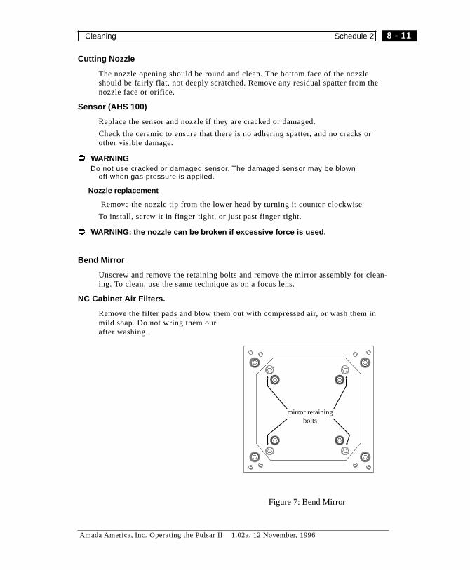
Cutting Nozzle
The nozzle opening should be round and clean. The bottom face of the nozzleshould be fairly flat, not deeply scratched. Remove any residual spatter from thenozzle face or orifice.
Sensor (AHS 100)
Replace the sensor and nozzle if they are cracked or damaged.
Check the ceramic to ensure that there is no adhering spatter, and no cracks orother visible damage.
Ü WARNINGDo not use cracked or damaged sensor. The damaged sensor may be blown
off when gas pressure is applied.
Nozzle replacement
Remove the nozzle tip from the lower head by turning it counter-clockwise
To install, screw it in finger-tight, or just past finger-tight.
Ü WARNING: the nozzle can be broken if excessive force is used.
Bend Mirror
Unscrew and remove the retaining bolts and remove the mirror assembly for clean-ing. To clean, use the same technique as on a focus lens.
NC Cabinet Air Filters.
Remove the filter pads and blow them out with compressed air, or wash them inmild soap. Do not wring them ourafter washing.
mirror retainingbolts
Figure 7: Bend Mirror
8 - 11
Amada America, Inc. Operating the Pulsar II 1.02a, 12 November, 1996
Cleaning Schedule 2
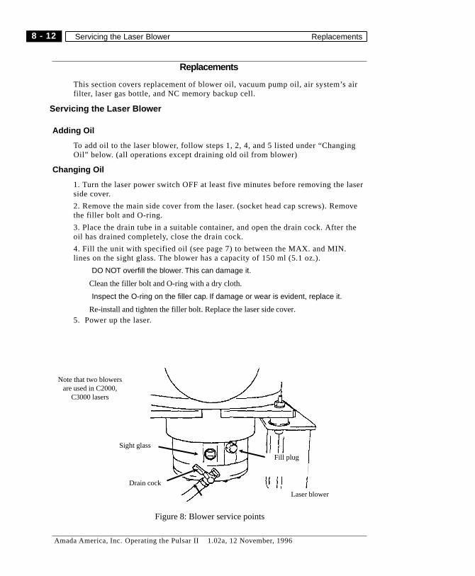
Replacements
This section covers replacement of blower oil, vacuum pump oil, air system’s airfilter, laser gas bottle, and NC memory backup cell.
Servicing the Laser Blower
Adding Oil
To add oil to the laser blower, follow steps 1, 2, 4, and 5 listed under “ChangingOil” below. (all operations except draining old oil from blower)
Changing Oil
1. Turn the laser power switch OFF at least five minutes before removing the laserside cover.
2. Remove the main side cover from the laser. (socket head cap screws). Removethe filler bolt and O-ring.
3. Place the drain tube in a suitable container, and open the drain cock. After theoil has drained completely, close the drain cock.
4. Fill the unit with specified oil (see page 7) to between the MAX. and MIN.lines on the sight glass. The blower has a capacity of 150 ml (5.1 oz.).
� DO NOT overfill the blower. This can damage it.
Clean the filler bolt and O-ring with a dry cloth.
� Inspect the O-ring on the filler cap. If damage or wear is evident, replace it.
Re-install and tighten the filler bolt. Replace the laser side cover.5. Power up the laser.
Laser blower
Drain cock
Sight glass
Fill plug
Note that two blowersare used in C2000,
C3000 lasers
Figure 8: Blower service points
8 - 12
Amada America, Inc. Operating the Pulsar II 1.02a, 12 November, 1996
Servicing the Laser Blower Replacements

Servicing the Laser Vacuum Pump
1. Remove the main side cover from the laser. (socket head cap screws)
2. Remove the filler cap, place the drain tube in a suitable container, and open thedrain cock.
3. After the oil has drained completely, close the drain cock.Fill the unit with specified oil (see page 7) to just below the MAX. line on the sightglass. The vacuum pump has a capacity of 1.8 liters (61 fl. oz.)
� Inspect the O-ring on the filler cap. If damage or wear is evident, replace it.
Replace the side cover.4. Power up the laser and allow it to run for three minutes, and turn it off again.
5. Repeat steps 1-3. This assures that all contamination has been removed fromthe pump.
6. Log the service operation, and resume normal operations.
Figure 9: Laser Vacuum Pump
8 - 13
Amada America, Inc. Operating the Pulsar II 1.02a, 12 November, 1996
Replacements Servicing the Laser Vacuum Pump
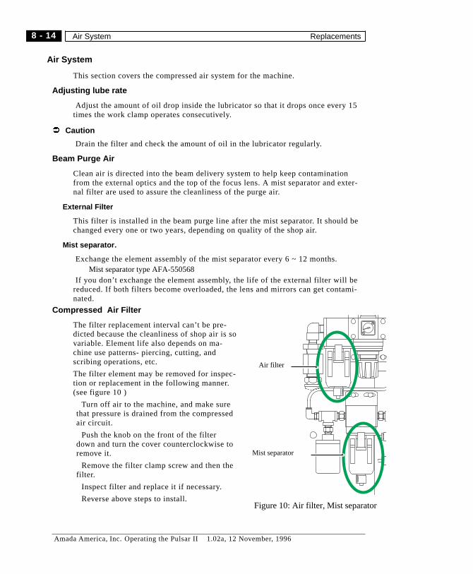
Air System
This section covers the compressed air system for the machine.
Adjusting lube rate
Adjust the amount of oil drop inside the lubricator so that it drops once every 15times the work clamp operates consecutively.
Ü Caution
Drain the filter and check the amount of oil in the lubricator regularly.
Beam Purge Air
Clean air is directed into the beam delivery system to help keep contaminationfrom the external optics and the top of the focus lens. A mist separator and exter-nal filter are used to assure the cleanliness of the purge air.
External Filter
This filter is installed in the beam purge line after the mist separator. It should bechanged every one or two years, depending on quality of the shop air.
Mist separator.
Exchange the element assembly of the mist separator every 6 ~ 12 months.Mist separator type AFA-550568
If you don’t exchange the element assembly, the life of the external filter will bereduced. If both filters become overloaded, the lens and mirrors can get contami-nated.
Compressed Air Filter
The filter replacement interval can’t be pre-dicted because the cleanliness of shop air is sovariable. Element life also depends on ma-chine use patterns- piercing, cutting, andscribing operations, etc.
The filter element may be removed for inspec-tion or replacement in the following manner.(see figure 10 )
Turn off air to the machine, and make surethat pressure is drained from the compressedair circuit.
Push the knob on the front of the filterdown and turn the cover counterclockwise toremove it.
Remove the filter clamp screw and then thefilter.
Inspect filter and replace it if necessary.
Reverse above steps to install.
Air filter
Mist separator
Figure 10: Air filter, Mist separator
8 - 14
Amada America, Inc. Operating the Pulsar II 1.02a, 12 November, 1996
Air System Replacements

Laser Gas bottle
Ü CAUTION: Do not open the main valve if anyone is in front of the regulator orgauge faces. If a regulator fails, the glass can shatter and cause injury.
Laser gas should be replaced when (or before) gas pressure drops to 145 psi.
To replace the bottle:
Make sure the laser is properly shut down.
Turn the gas cylinder’s main valve OFF.
Release the regulator/hose pressure by backing the regulator adjustment to zero.
Make sure that the replacement cylinder threads and sealing surfaces are clean anddry.
Remove the regulator from the exhausted cylinder and install it on the replace-ment cylinder.
Stand to one side or to the rear of the regulator and gently open the main gas valveon the cylinder.
Apply soap suds to the connection between the cylinder main valve and the regula-tor to confirm that there is no leakage.
Adjust the regulator for an output pressure of 21.4 to 28.4 psi (1.5 to 2 kgf/cm2)
NC Memory Backup Cell
This cell should be replaced every 12 months, or sooner if the NC signals analarm for low backup battery voltage.
Ü NOTE: Make sure to turn the NC ON prior to disconnecting the cell. Thisprevents loss of programs or data in memory during the operation.
Turn the NC ON.
Remove the cell holder cover.
Disconnect the old battery’s cable connector from the circuit board.
Connect the cable of the new cell to the circuit board.(FANUC A02B-0120-K106)
Replace the cover.
Press RESET on the NC keyboard.
8 - 15
Amada America, Inc. Operating the Pulsar II 1.02a, 12 November, 1996
Replacements Laser Gas bottle

Optical System
The optical system consists of the laser and its internal optics, six external beamdelivery mirrors, and a focus lens.
Systems with the 1500 Watt laser have two external mirrors in the Fanuc enclo-sure. With the 3000 Watt laser, all five beam delivery mirrors are outside the laserenclosure. This document covers cleaning of the external optics only.
Interlocks
The system is interlocked to prevent operation unless all optics are in place. Cer-tain of these optics must be removed and the and the corresponding interlock“cheated” or defeated to make test burns for alignment testing and adjustment.Suitable precautions must be taken to block the beam completely at the burn target.
DANGERWhen making test burns with the lens or any of the mirrors removed, the beam will
travel unt il it hits something .It remains dangerous for hundreds of feet.
The laser beam creates highly toxic gases when materials such as plastics andwoods are burned. Ventilation must be provided when making test burns. Avoid
breathing smoke or fumes.
8 - 16
Amada America, Inc. Operating the Pulsar II 1.02a, 12 November, 1996
Interlocks Optical System

Beam Path
The laser beam passes out of the laser and strikes mirrors A, B, 1, 2, 3, 4. The op-tics must be adjusted so that the laser beam passes through all optics cleanly. Itshould strike the focus lens in the middle regardless of machine motion.
If the lens/nozzle centering seems to change from Y+ to Y-mid to Y-minus, thenthe external alignment must be checked.
NCCabinet
CRT andMachine Operators Panel
Front Side
X-
Ax
is
si
de
Rear Side
Ope
ra
to
rS
id
e
Fanuc BendMirrors
L
R
ExternalBend Mirrors #1, 2
#3#4
Main Air UnitSolenoid Block
Assist Gas ConnectionsChiller Connections
Beam Path
Y-AxisLocate PINS
X-AxisLocate PINS
LC1212aIITop View
Y-Axis Positive Y-Axis Negative
Figure 11: Locations of mirrors (1500 Watt system)
8 - 17
Amada America, Inc. Operating the Pulsar II 1.02a, 12 November, 1996
Optical System Interlocks
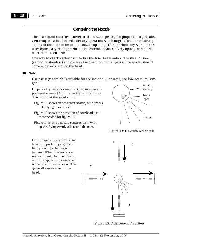
Centering the Nozzle
The laser beam must be centered in the nozzle opening for proper cutting results.Centering must be checked after any operation which might affect the relative po-sitions of the laser beam and the nozzle opening. These include any work on thelaser optics, any re-alignments of the external beam delivery optics, or replace-ment of the focus lens.
One way to check centering is to fire the laser beam onto a thin sheet of steel(carbon or stainless) and observe the direction of the sparks. The sparks shouldcome out evenly around the head.
Ü Note
Use assist gas which is suitable for the material. For steel, use low-pressure Oxy-gen.
If sparks fly only in one direction, use the ad-justment screws (4) to move the nozzle in thedirection that the sparks go.
Figure 13 shows an off-center nozzle, with sparksonly flying to one side.
Figure 12 shows the direction of nozzle adjust-ment needed for figure 13.
Figure 14 shows a nozzle centered well, withsparks flying evenly all around the nozzle.
Don’t expect every pierce tohave all sparks flying per-fectly evenly- that won’thappen. When the nozzle iswell-aligned, the machine isnot moving, and the materialis uniform, the sparks will begenerally even around thehead.
1
2
3
4
Figure 12: Adjustment Direction
sparks
nozzleopening
beamspot
Figure 13: Un-centered nozzle
8 - 18
Amada America, Inc. Operating the Pulsar II 1.02a, 12 November, 1996
Interlocks Centering the Nozzle
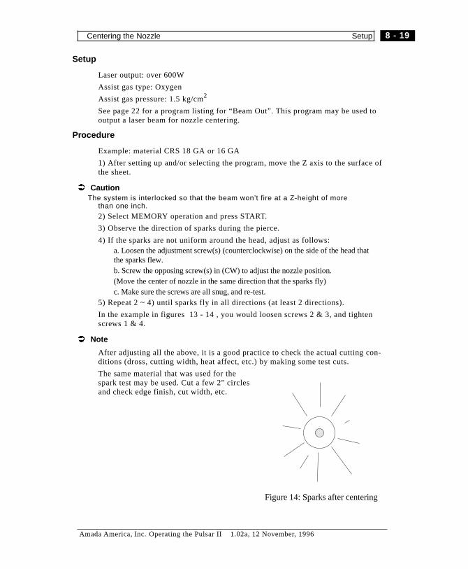
Setup
Laser output: over 600W
Assist gas type: Oxygen
Assist gas pressure: 1.5 kg/cm2
See page 22 for a program listing for “Beam Out”. This program may be used tooutput a laser beam for nozzle centering.
Procedure
Example: material CRS 18 GA or 16 GA
1) After setting up and/or selecting the program, move the Z axis to the surface ofthe sheet.
Ü CautionThe system is interlocked so that the beam won’t fire at a Z-height of more
than one inch.
2) Select MEMORY operation and press START.
3) Observe the direction of sparks during the pierce.
4) If the sparks are not uniform around the head, adjust as follows:a. Loosen the adjustment screw(s) (counterclockwise) on the side of the head thatthe sparks flew.b. Screw the opposing screw(s) in (CW) to adjust the nozzle position.(Move the center of nozzle in the same direction that the sparks fly)c. Make sure the screws are all snug, and re-test.
5) Repeat 2 ~ 4) until sparks fly in all directions (at least 2 directions).
In the example in figures 13 - 14 , you would loosen screws 2 & 3, and tightenscrews 1 & 4.
Ü Note
After adjusting all the above, it is a good practice to check the actual cutting con-ditions (dross, cutting width, heat affect, etc.) by making some test cuts.
The same material that was used for thespark test may be used. Cut a few 2" circlesand check edge finish, cut width, etc.
Figure 14: Sparks after centering
8 - 19
Amada America, Inc. Operating the Pulsar II 1.02a, 12 November, 1996
Centering the Nozzle Setup

Adjusting Focus Position
When you install a new focus lens, you must determine where it actually focuses.This varies from one lens to another, and requires physical testing. One techniquefor finding focus is presented below.
The focus position of a lens may be determined by making a series of cuts in thinsteel (.030 - .063) at varying focus settings. The focus setting which gives the nar-rowest cut is deemed to be at the surface of the material.
Cutting Test Setup
For program sample: see page 20Laser output 300 ~ 600WOperation speed F1200~F2000Assist gas type OxygenAssist gas pressure 2-3 kgf/cm.
5'1 2 3 4 5 1'2'3'4'
width of slot(kerf width)
Figure 15: Focus Test
8 - 20
Amada America, Inc. Operating the Pulsar II 1.02a, 12 November, 1996
Cutting Test Setup Adjusting Focus Position

Adjustment Procedure
1) Set the lens in the highest position
2) Create or select the test program.
3) Press “Start”.
The program will cut one slit and stop.
4) Lower the lens 0.5 mm by turning “Focus adjustment ring” of the head counter-clockwise while watching the scale
5) Repeat steps 3-4, and check cutting width at each position of the lens.
Ü Notes1. The narrowest slot indicates a focus at the surface or slightly below.2. The best focus position for cutting depends on material type and thickness. Thisprocedure just gives you an indication of the particular lens’s focus position.
In figure 15, each cut is made with a deeper focus, starting from “too high” andprogressing to “too low”.
After finding zero focus for a particular lens, it’s a good idea to confirm cut qual-ity on something like 16 GA CRS before going to difficult materials. This may bedone by cutting a few circles and examining the cut edges of both slug and hole.
8 - 21
Amada America, Inc. Operating the Pulsar II 1.02a, 12 November, 1996
Adjusting Focus Position Adjustment Procedure
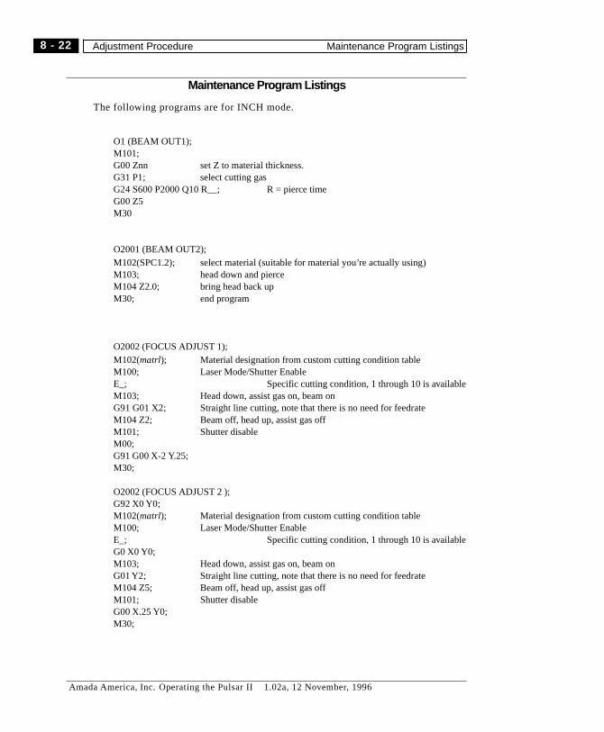
Maintenance Program Listings
The following programs are for INCH mode.
O1 (BEAM OUT1);M101;G00 Znn set Z to material thickness.G31 P1; select cutting gasG24 S600 P2000 Q10 R__; R = pierce timeG00 Z5M30
O2001 (BEAM OUT2);M102(SPC1.2); select material (suitable for material you’re actually using)M103; head down and pierceM104 Z2.0; bring head back upM30; end program
O2002 (FOCUS ADJUST 1);M102(matrl); Material designation from custom cutting condition tableM100; Laser Mode/Shutter EnableE_; Specific cutting condition, 1 through 10 is availableM103; Head down, assist gas on, beam onG91 G01 X2; Straight line cutting, note that there is no need for feedrateM104 Z2; Beam off, head up, assist gas offM101; Shutter disableM00;G91 G00 X-2 Y.25;M30;
O2002 (FOCUS ADJUST 2 );G92 X0 Y0;M102(matrl); Material designation from custom cutting condition tableM100; Laser Mode/Shutter EnableE_; Specific cutting condition, 1 through 10 is availableG0 X0 Y0;M103; Head down, assist gas on, beam onG01 Y2; Straight line cutting, note that there is no need for feedrateM104 Z5; Beam off, head up, assist gas offM101; Shutter disableG00 X.25 Y0;M30;
8 - 22
Amada America, Inc. Operating the Pulsar II 1.02a, 12 November, 1996
Adjustment Procedure Maintenance Program Listings

O2003 (HOLE-N-SQUARE)G90 G92 X0 Y0M102(SPC1.2)M100E_G112 X0 Y0 I.375 Hole cutting macro, note that “X” and “Y” are hole center andE_ positioning moveG111 X0 Y0I2 R.25M101M30
8 - 23
Amada America, Inc. Operating the Pulsar II 1.02a, 12 November, 1996
Maintenance Program Listings Adjustment Procedure

This page intentionally left blank
8 - 24
Amada America, Inc. Operating the Pulsar II 1.02a, 12 November, 1996
Adjustment Procedure Maintenance Program Listings

Chapter 9
ALARMS
Amada America, Inc. Operating the Pulsar II 1.02a, 12 November, 1996

Notes
9 - 2
Amada America, Inc. Operating the Pulsar II 1.02a, 12 November, 1996
Alarms -
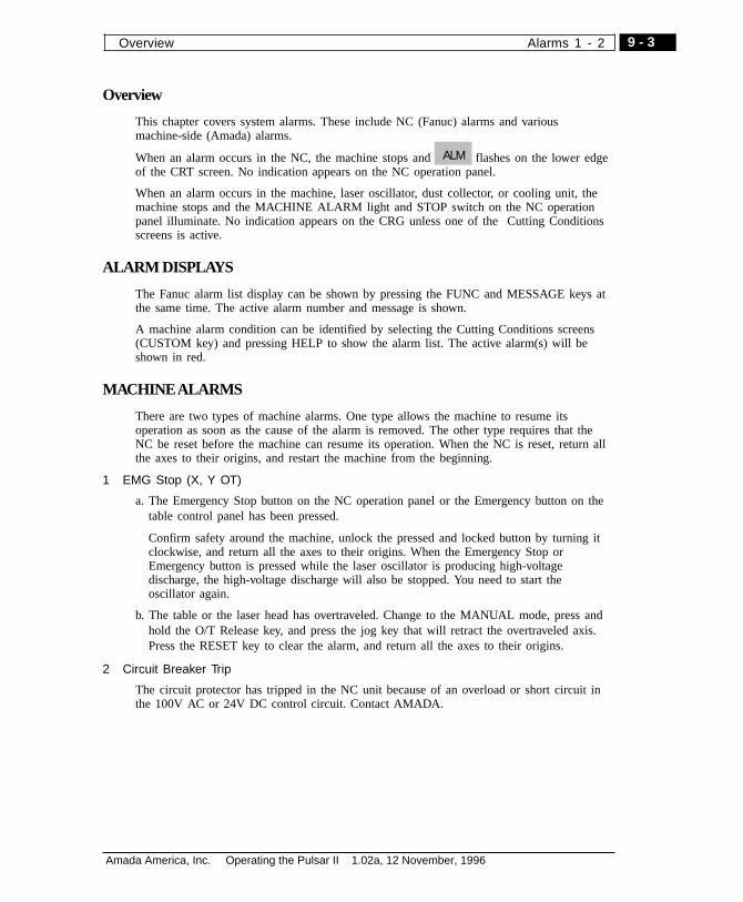
Overview
This chapter covers system alarms. These include NC (Fanuc) alarms and variousmachine-side (Amada) alarms.
When an alarm occurs in the NC, the machine stops and flashes on the lower edgeof the CRT screen. No indication appears on the NC operation panel.
When an alarm occurs in the machine, laser oscillator, dust collector, or cooling unit, themachine stops and the MACHINE ALARM light and STOP switch on the NC operationpanel illuminate. No indication appears on the CRG unless one of the Cutting Conditionsscreens is active.
ALARM DISPLAYS
The Fanuc alarm list display can be shown by pressing the FUNC and MESSAGE keys atthe same time. The active alarm number and message is shown.
A machine alarm condition can be identified by selecting the Cutting Conditions screens(CUSTOM key) and pressing HELP to show the alarm list. The active alarm(s) will beshown in red.
MACHINEALARMS
There are two types of machine alarms. One type allows the machine to resume itsoperation as soon as the cause of the alarm is removed. The other type requires that theNC be reset before the machine can resume its operation. When the NC is reset, return allthe axes to their origins, and restart the machine from the beginning.
1 EMG Stop (X, Y OT)
a. The Emergency Stop button on the NC operation panel or the Emergency button on thetable control panel has been pressed.
Confirm safety around the machine, unlock the pressed and locked button by turning itclockwise, and return all the axes to their origins. When the Emergency Stop orEmergency button is pressed while the laser oscillator is producing high-voltagedischarge, the high-voltage discharge will also be stopped. You need to start theoscillator again.
b. The table or the laser head has overtraveled. Change to the MANUAL mode, press andhold the O/T Release key, and press the jog key that will retract the overtraveled axis.Press the RESET key to clear the alarm, and return all the axes to their origins.
2 Circuit Breaker Trip
The circuit protector has tripped in the NC unit because of an overload or short circuit inthe 100V AC or 24V DC control circuit. Contact AMADA.
ALM
9 - 3
Amada America, Inc. Operating the Pulsar II 1.02a, 12 November, 1996
Overview Alarms 1 - 2

3 Air Pressure down
The main air inlet pressure has dropped below 3 kgf/cm2 (43 psi).
Check the inlet pressure and/or your shop air system. Return the pressure to 5.7 kgf/cm2(82 psi) or more. Press the RESET key to clear the alarm.
5 Mirror interlock
a. One of the bend mirrors is overheated. Wait until the bend mirror cools off and thealarm will clear. If the alarm condition does not clear or repeats, contact AMADA.
b. One of the bend mirrors is not correctly installed. Correctly reinstall the bend mirror.
6 Z Sensor malfunction
The nozzle has contacted the worksheet, or the gap between the tip of the nozzle and theworksheet has fallen below 0.1mm. Press the Sensor ON/OFF button and return all theaxes to their origins. Inspect the nozzle and sensor for spatter, and the worksheet forspatter or other foreign matter. Check the content of the program, and correct the programif necessary. On the AHS control panel, press the RESET button to clear the alarm.
7 Chiller Alarm
A fault signal has been received form the cooling unit. Contact AMADA.
8 Chiller Abnormal
Contact AMADA.
9 Gage block up
Can’t move or run machine with gage block (pins) in UP position.
10 Part didn’t fall
(option) Part-drop sensor didn’t detect part drop through work chute
11 Assist Gas Pressure Down
a. The assist gas pressure has dropped below 0.2 kgf/cm2 (2.8 psi). Inspect the residualpressure in the assist gas cylinder, and if it is under 3-5 kgf/cm2 (128 psi), have thecylinder changed by the supplier.
b. The main valve of the assist gas cylinder is closed, or the regulator knob on the assistgas pressure setup panel is turned fully counterclockwise. Check the main valve orregulator knob.
c. The assist gas that is not connected with the machine has been specified. Cheek the typeof the assist gas.
12 Laser H/V OFF
13 Al Cut cover open
14 Work Clamp Open
Clamps are open and machine is in MEMORY or MDI mode.
9 - 4
Amada America, Inc. Operating the Pulsar II 1.02a, 12 November, 1996
Alarms 3 - 14 MACHINE ALARMS
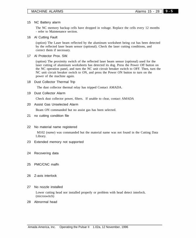
15 NC Battery alarm
The NC memory backup cells have dropped in voltage. Replace the cells every 12 months- refer to Maintenance section.
16 Al Cutting Fault
(option) The Laser beam reflected by the aluminum worksheet being cut has been detectedby the reflected laser beam sensor (optional). Check the laser cutting conditions, andcorrect them if necessary.
17 Al Protector Prox. SW.
(option) The proximity switch of the reflected laser beam sensor (optional) used for thelaser cutting of aluminum worksheets has detected its dog. Press the Power Off button onthe NC operation panel, and turn the NC unit circuit breaker switch to OFF. Then, turn theNC unit circuit breaker switch to ON, and press the Power ON button to turn on thepower of the machine again.
18 Dust Collector Thermal Trip
The dust collector thermal relay has tripped Contact AMADA.
19 Dust Collector Alarm
Check dust collector power, filters. If unable to clear, contact AMADA
20 Assist Gas Unselected Alarm
Beam ON commanded but no assist gas has been selected.
21 no cutting condition file
22 No material name registered
M102 (name) was commanded but the material name was not found in the Cutting DataLibrary.
23 Extended memory not supported
24 Recovering data
25 PMC/CNC malfn
26 Z-axis interlock
27 No nozzle installed
Lower cutting head nor installed properly or problem with head detect interlock.(microswitch)
28 Abnormal head
9 - 5
Amada America, Inc. Operating the Pulsar II 1.02a, 12 November, 1996
MACHINE ALARMS Alarms 15 - 28
29 Scrap box front door open
30 Scrap box back door open
31 Maintenance Mode
32 Work Chute open
Alarm condition in any but MEMORY or MDI mode. In MEMORY or MDI mode,inhibits
33 Dead Zone alarm
Can occur if the machine does not have escaping workclamps or if the AVOID CANCELswitch (on the NC Operation Panel) is ON.
The laser head has entered the workclamp dead zone where it may collide with theworkclamps. Change to Manual mode, raise the laser head clear of the workclamps, andmove it in the + Y direction out of the dead zone. To execute the same program, changethe clapm positions or shift the laser cutting position in the worksheet so that the laserhead does not enter the workclamp dead zone.
34 Safety mat alarm
35 Pierce alarm
36 M10 Watch Dog alarm
37 M11 Watch Dog alarm
38 M760 Watch Dog alarm
39 M762 Watch Dog alarm
40 M80 Watch Dog alarm
41 Front cover open
9 - 6
Amada America, Inc. Operating the Pulsar II 1.02a, 12 November, 1996
Alarms 29 - 41 MACHINE ALARMS
HeightSensorAlarms
The AHS-100 height sensor has a self diagnosis function in the controller. When an alarmoccurs in the Height Sensor, the machine stops and the RESET button on the AHS controlpanel lights up. Clear the alarm as described below.
Alarm during calibration.
1) Be sure that the “SENSOR” switch on the NC operation panel is “on”.
2) Be sure that “OVERRIDE” on NC operation panel is set to 100%.
3) Be sure that the nozzle and materials have no water, oil, and dust. Clean them asneeded.
4) Be sure that the worksheet is clamped.
After making sure of the above, cancel the alarm by pressing the “Reset” switch on theAHS control and calibrate by running program 9000.
Alarm during laser processing:
Usual causes:
Either the nozzle touched the cutting material, or the gap became less than 0.1mm.
1) Make sure that the selected material’s worksheet thickness value is correct. Seepage 7-12 for more information.
2) Make sure that the nozzle and the sensor are clean and undamaged. Make sure that theworkpiece surface is clean.
3) As the material was being cut, a cut edge may have raised up enough to touch thenozzle and cause the alarm. This may call for part-program revisions.
4) When slope cutting, if the feedrate is too high, the Z axis cannot follow and the nozzlemay touch the workpiece. Reduce the feedrate.
Refer to Alarm 6 in the previous section (page 4)and cancel the alarm. If you cannot,contact AMADA.
Make sure of the above, cancel the alarm by pressing Reset switch and resume processing.
Other errors
When you cannot cancel the alarm by pressing Reset switch on the AHS control panel,check the following.
1) Make sure that cables are properly connected.
2) Remove any water, oil, and spatters from the nozzle.
3) Try a sensor on the machine that is known to be ok.
If these steps don’t restore normal operation, the AHS-100 system may be broken. ContactAMADA.
9 - 7
Amada America, Inc. Operating the Pulsar II 1.02a, 12 November, 1996
Height Sensor Alarms Alarms 41 - 41
AHCAlarms(Option,Altaironly)
The Auto Head Changer is not offered on Pulsar.
2050 Message No head
Contents Clamp command was made when there is no head.
(note) When turning on the power or an emergency stop, this message is is displayed ifthere is no head.
Remarks This message does not cause the field hold, a normal operation can be performed.Start to operate AHC system to erase this message.
2051 Head LS abnormal
LS for confirming clamp and unclamp is not working properly.
Contact AMADA.
2052 Head C/UC command mistakenly.
Clamp and unclamp were commanded outside AHC adjustment domain.
*It occurs during AHC adjustment.
2053 Magazine cover is closed.
A magazine cover is closed outside AHC adjustment domain.
*It occurs during AHC adjustment.
2054 Magazine cover is open.
NC start was commanded when the magazine cover was open.
Close the magazine cover.
2055 Magazine cover LS abnormal
LS for confirming to open or close magazine cover is not working properly.
Contact AMADA.
2056 AHC mode +X 0.T
It entered AHC adjustment domain when AHC is not being executed.
Move to -X side and reset.
2057 Power stop alarm during AHC.
When the power stops during AHC clamp operation, it occurs if you start the power again.
Contact AMADA.
(note) “It occurs during AHC adjustment” indicated with an asterisk is an alarm occurringwhen a service man adjusts AHC. Usually it does not occur.
9 - 8
Amada America, Inc. Operating the Pulsar II 1.02a, 12 November, 1996
Alarms 2050 - 2057 AHC Alarms (Option, Altair only)
NCAlarms
NC alarms may be cleared by pressing RESET.
If a program was in execution when the alarm occurred, it can not be continued. Returnthe machine axes to the origins, and begin the program from the beginning.
Program Error (P/S alarms)
000 Turn off the power
A parameter has been changed which requires the NC to re-initialize. Turn the power off,then on again.
001 TH parity alarm
TH alarm (an incorrect number of holes have been punched for a character in the tape).Correct the tape.
002 TV parity alarm
TV parity alarm produced only when TV check is effective. An incorrect number ofcharacters have been punched for a block in the tape.
003 Data with an excessive number of digits has been found.
Data with an excessive number of digits has been found. (Refer to Max command value)
004 No address in the beginning of the block.
A word without address and starts with a numeral, minus sign, or decimal point has beenfound at the beginning of the block. Example: 1.2 Y42.1;
005 No data after address
An address is not followed by data, but by the address of the next word or anend-of-block code has been found. Example: X;
006 Sign input error
A word with a misplaced minus sign or two minus signs has been found.
007 Digit input error
A word with a misplaced decimal point or two decimal points has been found. Example:X1..01;
009 Address input error
An address unable to be used for significant information has been input.
010 An invalid G-code has been found.
A G-code corresponding to a function not added (option not present) has been found.
011 Cutting feed rate not commanded.
The cutting feed rate has not been specified or is invalid.
014 Synchronous feed (G95) commanded and not available.
G95 (synchronous feed option) not present on NC.
015 Too many axes moved simultaneously
Can’t move more than the number of “simultaneously controlled axes” at once.
9 - 9
Amada America, Inc. Operating the Pulsar II 1.02a, 12 November, 1996
NC Alarms Alarms 000 - 015

021 Axis command only available in designated plane.
Circular arc interpolation can only be performed in designated plane. Use G17, G18, G19for plane selection.
025 F0 cannot be commanded with G02/G03.
In circular interpolation, F0 has been commanded.
027 No axis designation to G43/G44.
There is no axis designation in the block of G43 and G44 in the laser beam pathcompensation type C. Other axis has been used without offset canceling in the laser beampath compensation type C.
028 Error in a plane select command.
More than 2 axes in the same direction have been commanded in the plane selectcommand.
029 Offset amount out of range.
The offset amount value selected with H code is too large.
030 Offset number out of range.
The offset number commanded with D/H code of the laser beam path compensation is toobig.
031 P command error in G10.
P value designating an offset number in the offset amount program is missing or too big.
032 Offset amount out of range in G10.
The offset amount designated is too big in the offset amount program input (G10) or inwriting the offset amount with a system variable.
033 The point of intersection cannot be calculated.
The point of intersection cannot be calculated for the laser beam path compensation.
034 Can’t Start or Cancel laser beam path compensation during G02/G03.
In the laser beam path compensation C, Start or Cancel during G02/G03 mode has beenfound.
035 Unable to command G39.
G39 has been commanded in the laser beam compensation B cancel mode or outside theoffset plane.
036 Unable to command G31.
Skip cutting has been commanded during the laser beam compensation mode.
037 Unable to switch the compensation plane.
The compensation plane (G17, G18, G19) has been switched during the laser beam pathcompensation C or G40 has been commanded in the laser beam path compensation B.
038 Overcutting at arc start or end point.
The radius at the arc start or end point is zero for the laser beam path compensation andlikely to cause overcutting.
9 - 10
Amada America, Inc. Operating the Pulsar II 1.02a, 12 November, 1996
Alarms 021 - 038 Program Error (P/S alarms)

041 Overcutting in the laser beam path compensation.
The laser beam path compensation may result in overcutting. Blocks without move suchas interpolation function and dwell function have been commanded consecutively morethan 2 blocks in the laser beam path compensation mode.
042 Unable to command the laser beam position compensation.
The laser beam position compensation has been commanded during the laser beam pathmode.
044 No G27 ~ G30 during the canned cycle.
G27 ~ G30 has been commanded during the canned cycle mode.
046 Error in 2nd, 3rd, 4th, Zero Return command.
Commands other than P2, P3, P4 have been made in the 2nd, 3rd, and 4th reference pointreturn command.
050 Cut plane/corner has been commanded during cutting a screw.
Cut plane and corner R have been commanded during cutting screws.
051 Next move is inappropriate to cut plane/corner R.
The move or move amount of the block next to the block which cut plane w/ arbitraryangle and corner R were commanded is inappropriate.
052 Next block command not G01.
The next block command to the block which cut plane with arbitrary angle and corner Rwere commanded is not G01.
053 Excessive address commands.
More than two commands among I, J R have been commanded in the cut plane witharbitrary angle and corner R or in the diagram size direct input, C or R.
054 Cut plane/corner R command is a taper command.
The block to which the cut plane with arbitrary angle and corner R are commanded is ataper command.
055 Less move than the cut plane/corner R amount.
In the block to which the cut plane with arbitrary angle and corner R are commanded, themove amount is less than the cut plane and corner R amount.
056 No end point and angle designation.
In the block command next to the block of angle designation only (A..), both end pointdesignation and angle designation have not been input. I(J) has been commanded to Xaxis (Z axis) in the cut plane command.
057 The end point of the block cannot be calculated.
The end point of the block has not been calculated correctly in the diagram size directinput.
058 End point of the block cannot be found.
The end point of the block has not been found in the diagram size direct input.
059 Program number not found.
The specified program number has not been found.
9 - 11
Amada America, Inc. Operating the Pulsar II 1.02a, 12 November, 1996
Program Error (P/S alarms) Alarms 041 - 059
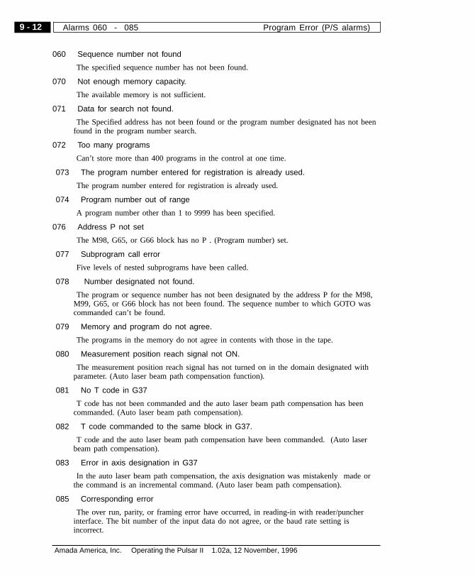
060 Sequence number not found
The specified sequence number has not been found.
070 Not enough memory capacity.
The available memory is not sufficient.
071 Data for search not found.
The Specified address has not been found or the program number designated has not beenfound in the program number search.
072 Too many programs
Can’t store more than 400 programs in the control at one time.
073 The program number entered for registration is already used.
The program number entered for registration is already used.
074 Program number out of range
A program number other than 1 to 9999 has been specified.
076 Address P not set
The M98, G65, or G66 block has no P . (Program number) set.
077 Subprogram call error
Five levels of nested subprograms have been called.
078 Number designated not found.
The program or sequence number has not been designated by the address P for the M98,M99, G65, or G66 block has not been found. The sequence number to which GOTO wascommanded can’t be found.
079 Memory and program do not agree.
The programs in the memory do not agree in contents with those in the tape.
080 Measurement position reach signal not ON.
The measurement position reach signal has not turned on in the domain designated withparameter. (Auto laser beam path compensation function).
081 No T code in G37
T code has not been commanded and the auto laser beam path compensation has beencommanded. (Auto laser beam path compensation).
082 T code commanded to the same block in G37.
T code and the auto laser beam path compensation have been commanded. (Auto laserbeam path compensation).
083 Error in axis designation in G37
In the auto laser beam path compensation, the axis designation was mistakenly made orthe command is an incremental command. (Auto laser beam path compensation).
085 Corresponding error
The over run, parity, or framing error have occurred, in reading-in with reader/puncherinterface. The bit number of the input data do not agree, or the baud rate setting isincorrect.
9 - 12
Amada America, Inc. Operating the Pulsar II 1.02a, 12 November, 1996
Alarms 060 - 085 Program Error (P/S alarms)
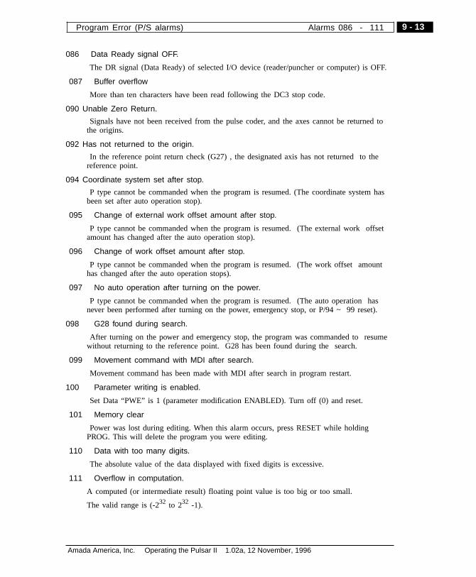
086 Data Ready signal OFF.
The DR signal (Data Ready) of selected I/O device (reader/puncher or computer) is OFF.
087 Buffer overflow
More than ten characters have been read following the DC3 stop code.
090 Unable Zero Return.
Signals have not been received from the pulse coder, and the axes cannot be returned tothe origins.
092 Has not returned to the origin.
In the reference point return check (G27) , the designated axis has not returned to thereference point.
094 Coordinate system set after stop.
P type cannot be commanded when the program is resumed. (The coordinate system hasbeen set after auto operation stop).
095 Change of external work offset amount after stop.
P type cannot be commanded when the program is resumed. (The external work offsetamount has changed after the auto operation stop).
096 Change of work offset amount after stop.
P type cannot be commanded when the program is resumed. (The work offset amounthas changed after the auto operation stops).
097 No auto operation after turning on the power.
P type cannot be commanded when the program is resumed. (The auto operation hasnever been performed after turning on the power, emergency stop, or P/94 ~ 99 reset).
098 G28 found during search.
After turning on the power and emergency stop, the program was commanded to resumewithout returning to the reference point. G28 has been found during the search.
099 Movement command with MDI after search.
Movement command has been made with MDI after search in program restart.
100 Parameter writing is enabled.
Set Data “PWE” is 1 (parameter modification ENABLED). Turn off (0) and reset.
101 Memory clear
Power was lost during editing. When this alarm occurs, press RESET while holdingPROG. This will delete the program you were editing.
110 Data with too many digits.
The absolute value of the data displayed with fixed digits is excessive.
111 Overflow in computation.
A computed (or intermediate result) floating point value is too big or too small.
The valid range is (-232 to 232 -1).
9 - 13
Amada America, Inc. Operating the Pulsar II 1.02a, 12 November, 1996
Program Error (P/S alarms) Alarms 086 - 111

112 Zero divisor
Zero is entered as divisor. ( including tan (90°)
113 Unable to use designated function.
A function has been commanded in the custom macro which is not permitted there.
114 Format error in macro
An error has been found in a format other than a <formula>.
115 Variable number error
Values which are not defined as a variable number were specified in a custom macro or inhigh-speed machining.
The content of the header is inappropriate. This alarm occurs in the following cases.
1) There is no header corresponding to the calling manufacture cycle number commanded.
2) The value of the cycle connection information is out of the range (0 ~ 999)
3) The number of data in the header are out of the range ( 0 ~ 32767)
4) The storage start data variable number of the executable format data is out of range (#20000 ~ 85535)
5) The last storage data variable number of the executable format data is out of the range(# 85535)
6) The storage start data variable number of the executable format data and the variablenumber used in the header overlap.
116 Illegal or write protected variable
Can’t assign values to write-protected variable, or an illegal variable has been assigned inthe left statement.
118 Parentheses overflow.
The number of parentheses has exceeded the algebraic nesting limit of five levels.
119 Error in argument
A negative argument has been entered for SQRT or BCD. Or the argument for BCDcontains data other than 0 to 9.
122 Macro modal double command.
Nested macro programs have been called exceeding two levels.
123 Unable to use macro command.
A macro control command has been used for DNC operation.
124 No Do-End correspondence.
Do and End have been incorrectly specified, which must have a relationship of 1:1
125 Error in format
An error has been found in the format of an expression.
126 Error in DO sentence.
In DOn, “n” has been incorrectly specified, which must be 1 to 3.
9 - 14
Amada America, Inc. Operating the Pulsar II 1.02a, 12 November, 1996
Alarms 112 - 126 Program Error (P/S alarms)

127 NC and Macro command exist together.
An NC command and a macro command are present in the same block.
128 Error in sequence No. of macro
In GOTO, “n” has been incorrectly specified, which must be 0 to 9999.
The sequence no. to which GOTO was commanded cannot be found.
129 Error in argument address
An invalid address has been used in an argument.
130 Error in axis control command.
The axis control command from PMC has been made to the axis CNC control. Or theaxis control command from CNC has been made to the axis PMC controls.
131 Alarm number is too large in the external alarm message.
More than 5 alarms have occurred in the external alarm message.
132 No. alarm number in the external alarm message.
There is no alarm number corresponding to the clear of the external alarm message.
133 Data error in the external alarm message.
There is an error in small separated data in the external alarm message or in the externaloperator message.
135 Error in angle command.
The angle determining a position for index table calculation has been commandedwithout integral multiplication of min. angle value.
136 Unable to command to the other axis simultaneously.
The other axes have been commanded with B axis.
139 Unable to select axis in PMC axis control.
The axis has been selected during PMC axis control.
141 Unable to command G51 during the laser beam compensation
G51 (scaling on) has been commanded during the laser beam compensation.
142 Error in scaling magnification
The scaling magnification has been instructed other than 1 ~ 999999 values.
143 Over max instruction value
As a result of scaling, values of movement amount, coordinate amount, or circle-arcdiameter are too big..
144 Different circle-arc and plane
The coordinate relation plane or circle and the laser beam path compensation plane have tocorrespond.
145 Error in polar coordinate compensation.
The conditions when the polar coordinate compensation starts or is canceled are incorrect.
a. G21.1/G13.1 have been instructed other than in G40 mode.
b. There is an error in the plane selection (Parameter No. 5460, 5461 incorrect setting).
9 - 15
Amada America, Inc. Operating the Pulsar II 1.02a, 12 November, 1996
Program Error (P/S alarms) Alarms 127 - 145

146 G code unable to instruct.
G code which cannot be instructed has been instructed during the polar coordinatecompensation.
147 Error in a setting value.
The decelerate ratio and decision angle of the auto corner override is out of the settingpossible range.
150 Laser beam group number is out of the range.
The laser beam group number is over the max value.
151 Laser beam group not set.
The laser beam group designated in the manufacture program.
152 The number of laser beam is over the max value.
The number of laser beam within a group is over the possible registration max value.
153 Unable to find T code.
T code is not stored in the block where it is supposed to be stored.
154 No group instruction
When there is no group instruction, H99 or D99 were instructed.
155 T code is not corresponding to the group.
T code of the same block as M06 is not corresponding to the group used in themanufacture group.
156 No P/L instruction for laser beam group setting.
The program for setting laser beam has no beginning P, L instruction.
157 The number of laser beam group is over the max.
The number of laser beam group is over the max value.
158 Durable value of laser beam is out of the range.
The durable value of laser beam to be set is too large.
159 The power was turned off during setting.
The power was turned off while executing the program for setting.
175 Error in cylinder interpolation.
The condition during the cylinder interpolation start or cancel is incorrect. Instruct “G07.1Rotation_axis_name cylinder_radius” to activate Cylinder Interpolation mode.
176 G mode not available during cylinder interpolation mode.
The G mode commanded is not available during cylinder interpolation mode. Thefollowing G modes cannot be instructed during the cylinder interpolation mode.
a. Position determination (including G28, G53, G73, G74, G76, G80 ~ G89 which create acycle of fast feed).
b. Work coordinate system (G92, G54 ~ G59).
c. Local coordinate system (G52).
9 - 16
Amada America, Inc. Operating the Pulsar II 1.02a, 12 November, 1996
Alarms 146 - 176 Program Error (P/S alarms)
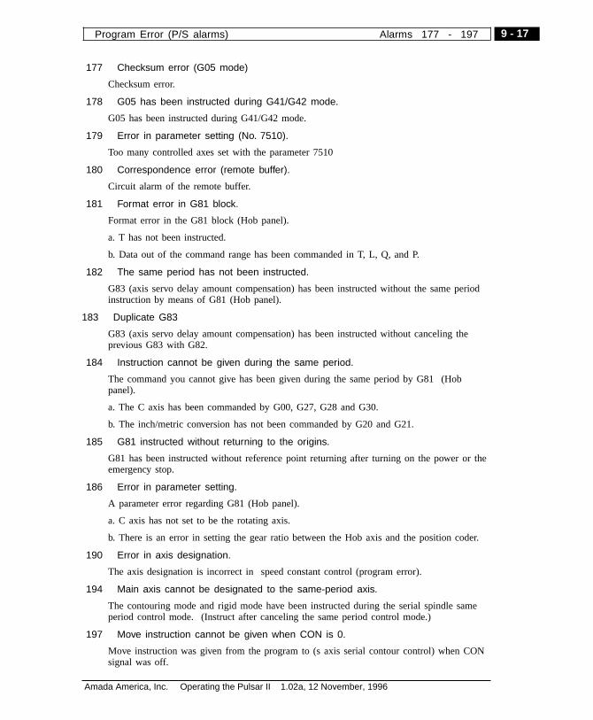
177 Checksum error (G05 mode)
Checksum error.
178 G05 has been instructed during G41/G42 mode.
G05 has been instructed during G41/G42 mode.
179 Error in parameter setting (No. 7510).
Too many controlled axes set with the parameter 7510
180 Correspondence error (remote buffer).
Circuit alarm of the remote buffer.
181 Format error in G81 block.
Format error in the G81 block (Hob panel).
a. T has not been instructed.
b. Data out of the command range has been commanded in T, L, Q, and P.
182 The same period has not been instructed.
G83 (axis servo delay amount compensation) has been instructed without the same periodinstruction by means of G81 (Hob panel).
183 Duplicate G83
G83 (axis servo delay amount compensation) has been instructed without canceling theprevious G83 with G82.
184 Instruction cannot be given during the same period.
The command you cannot give has been given during the same period by G81 (Hobpanel).
a. The C axis has been commanded by G00, G27, G28 and G30.
b. The inch/metric conversion has not been commanded by G20 and G21.
185 G81 instructed without returning to the origins.
G81 has been instructed without reference point returning after turning on the power or theemergency stop.
186 Error in parameter setting.
A parameter error regarding G81 (Hob panel).
a. C axis has not set to be the rotating axis.
b. There is an error in setting the gear ratio between the Hob axis and the position coder.
190 Error in axis designation.
The axis designation is incorrect in speed constant control (program error).
194 Main axis cannot be designated to the same-period axis.
The contouring mode and rigid mode have been instructed during the serial spindle sameperiod control mode. (Instruct after canceling the same period control mode.)
197 Move instruction cannot be given when CON is 0.
Move instruction was given from the program to (s axis serial contour control) when CONsignal was off.
9 - 17
Amada America, Inc. Operating the Pulsar II 1.02a, 12 November, 1996
Program Error (P/S alarms) Alarms 177 - 197
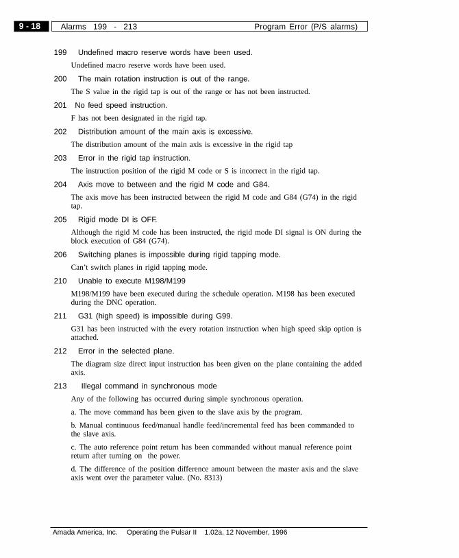
199 Undefined macro reserve words have been used.
Undefined macro reserve words have been used.
200 The main rotation instruction is out of the range.
The S value in the rigid tap is out of the range or has not been instructed.
201 No feed speed instruction.
F has not been designated in the rigid tap.
202 Distribution amount of the main axis is excessive.
The distribution amount of the main axis is excessive in the rigid tap
203 Error in the rigid tap instruction.
The instruction position of the rigid M code or S is incorrect in the rigid tap.
204 Axis move to between and the rigid M code and G84.
The axis move has been instructed between the rigid M code and G84 (G74) in the rigidtap.
205 Rigid mode DI is OFF.
Although the rigid M code has been instructed, the rigid mode DI signal is ON during theblock execution of G84 (G74).
206 Switching planes is impossible during rigid tapping mode.
Can’t switch planes in rigid tapping mode.
210 Unable to execute M198/M199
M198/M199 have been executed during the schedule operation. M198 has been executedduring the DNC operation.
211 G31 (high speed) is impossible during G99.
G31 has been instructed with the every rotation instruction when high speed skip option isattached.
212 Error in the selected plane.
The diagram size direct input instruction has been given on the plane containing the addedaxis.
213 Illegal command in synchronous mode
Any of the following has occurred during simple synchronous operation.
a. The move command has been given to the slave axis by the program.
b. Manual continuous feed/manual handle feed/incremental feed has been commanded tothe slave axis.
c. The auto reference point return has been commanded without manual reference pointreturn after turning on the power.
d. The difference of the position difference amount between the master axis and the slaveaxis went over the parameter value. (No. 8313)
9 - 18
Amada America, Inc. Operating the Pulsar II 1.02a, 12 November, 1996
Alarms 199 - 213 Program Error (P/S alarms)
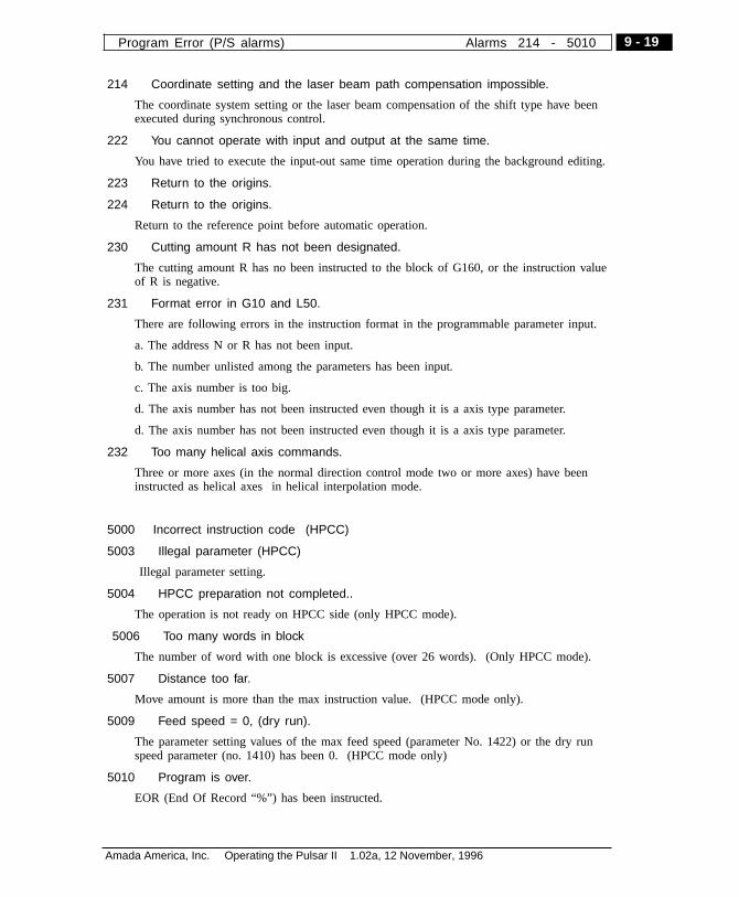
214 Coordinate setting and the laser beam path compensation impossible.
The coordinate system setting or the laser beam compensation of the shift type have beenexecuted during synchronous control.
222 You cannot operate with input and output at the same time.
You have tried to execute the input-out same time operation during the background editing.
223 Return to the origins.
224 Return to the origins.
Return to the reference point before automatic operation.
230 Cutting amount R has not been designated.
The cutting amount R has no been instructed to the block of G160, or the instruction valueof R is negative.
231 Format error in G10 and L50.
There are following errors in the instruction format in the programmable parameter input.
a. The address N or R has not been input.
b. The number unlisted among the parameters has been input.
c. The axis number is too big.
d. The axis number has not been instructed even though it is a axis type parameter.
d. The axis number has not been instructed even though it is a axis type parameter.
232 Too many helical axis commands.
Three or more axes (in the normal direction control mode two or more axes) have beeninstructed as helical axes in helical interpolation mode.
5000 Incorrect instruction code (HPCC)
5003 Illegal parameter (HPCC)
Illegal parameter setting.
5004 HPCC preparation not completed..
The operation is not ready on HPCC side (only HPCC mode).
5006 Too many words in block
The number of word with one block is excessive (over 26 words). (Only HPCC mode).
5007 Distance too far.
Move amount is more than the max instruction value. (HPCC mode only).
5009 Feed speed = 0, (dry run).
The parameter setting values of the max feed speed (parameter No. 1422) or the dry runspeed parameter (no. 1410) has been 0. (HPCC mode only)
5010 Program is over.
EOR (End Of Record “%”) has been instructed.
9 - 19
Amada America, Inc. Operating the Pulsar II 1.02a, 12 November, 1996
Program Error (P/S alarms) Alarms 214 - 5010
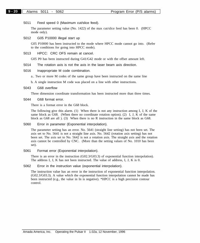
5011 Feed speed 0 (Maximum cut/slice feed).
The parameter setting value (No. 1422) of the max cut/slice feed has been 0. (HPCCmode only).
5012 G05 P10000 illegal start up
G05 P10000 has been instructed to the mode where HPCC mode cannot go into. (Referto the conditions for going into HPCC mode).
5013 HPCC: CRC OFS remain at cancel.
G05 P0 has been instructed during G41/G42 mode or with the offset amount left.
5014 The rotation axis is not the axis in the laser beam axis direction.
5016 Inappropriate M code combination.
a.. Two or more M codes of the same group have been instructed on the same line
b. A single instruction M code was placed on a line with other instructions.
5043 G68 overflow
Three dimension coordinate transformation has been instructed more than three times.
5044 G68 format error.
There is a format error in the G68 block.
The following give this alarm. (1) When there is not any instruction among I, J, K of thesame block as G68. (When there no coordinate rotation option). (2) I, J, K of the sameblock as G68 are all ). (3) When there is no R instruction in the same block as G68.
5060 Error in parameter (Exponential interpolation).
The parameter setting has an error. No. 5641 (straight line setting) has not been set. Theaxis set to No. 5641 is not a straight line axis. No. 5642 (rotation axis setting) has notbeen set. The axis set to No. 5642 is not a rotation axis. The straight axis and the rotationaxis cannot be controlled by CNC. (More than the setting values of No. 1010 has beenset).
5061 Format error (Exponential interpolation).
There is an error in the instruction (G02.3/G03.3) of exponential function interpolation).The address I, J, K has not been instructed. The value of address, I, J, K is 0.
5062 Error in the instruction value (exponential interpolation).
The instruction value has an error in the instruction of exponential function interpolation.(G02.3/G03.3). A value which the exponential function interpolation cannot be made hasbeen instructed (e.g., the value in In is negative). *HPCC is a high precision contourcontrol.
9 - 20
Amada America, Inc. Operating the Pulsar II 1.02a, 12 November, 1996
Alarms 5011 - 5062 Program Error (P/S alarms)
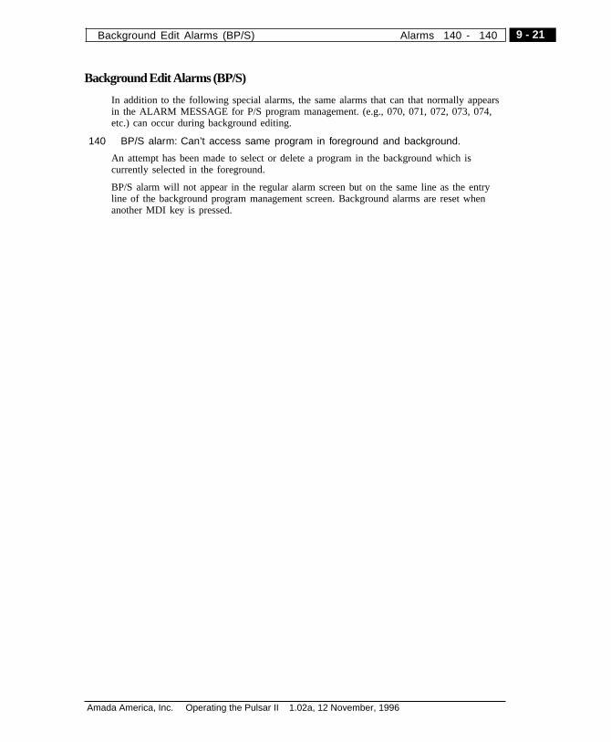
BackgroundEditAlarms (BP/S)
In addition to the following special alarms, the same alarms that can that normally appearsin the ALARM MESSAGE for P/S program management. (e.g., 070, 071, 072, 073, 074,etc.) can occur during background editing.
140 BP/S alarm: Can’t access same program in foreground and background.
An attempt has been made to select or delete a program in the background which iscurrently selected in the foreground.
BP/S alarm will not appear in the regular alarm screen but on the same line as the entryline of the background program management screen. Background alarms are reset whenanother MDI key is pressed.
9 - 21
Amada America, Inc. Operating the Pulsar II 1.02a, 12 November, 1996
Background Edit Alarms (BP/S) Alarms 140 - 140

Absolute PulseCode (APC) Alarms
300 Zero-return: n-axis n-axis (1-8) needs to be Zero-returned manually.
301 APC alarm: axis communication
APC communication error has been found in n-axis (1-8).(Data transmission error )
302 APC alarm: n-axis overtime
APC overtime error has been found in n-axis (1-8).(Data transmission error)
303 APC alarm: n-axis framing
APC framing error has been found in n-axis (1-8).(Data transmission error)
304 APC alarm: n-axis parity
APC parity error has been found in n-axis (1-8).(Data transmission error)
305 APC alarm: n-axis pulse missing
APC pulse (missing) error has been found in n-axis (1-8).(APC alarm)
306 APC alarm: Zero (voltage) in n-axis battery
The voltage of the n-axis (1-8) APC battery has been insufficient (0 voltage) to retain data.(APC alarm)
307 APC alarm: Low voltage in n-axis (1)
The voltage of n-axis (1-8) is currently low, requires battery replacement (APC alarm)
308 APC alarm: Low voltage in n-axis (2)
The voltage of n-axis (1-8) has been detected low (including when the power has beenturned off )
The battery needs replacement. (APC alarm)
9 - 22
Amada America, Inc. Operating the Pulsar II 1.02a, 12 November, 1996
Alarms 300 - 308 Absolute Pulse Code (APC) Alarms
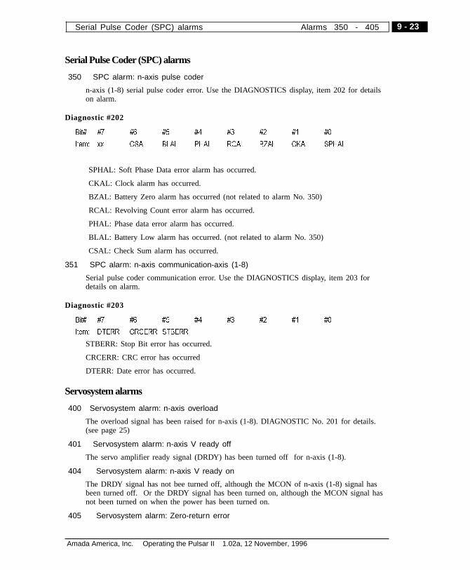
Serial Pulse Coder (SPC) alarms
350 SPC alarm: n-axis pulse coder
n-axis (1-8) serial pulse coder error. Use the DIAGNOSTICS display, item 202 for detailson alarm.
Diagnostic #202
Bit# #7 #6 #5 #4 #3 #2 #1 #0
Item: xx CSAL BLAL PHAL RCAL BZAL CKAL SPHAL
SPHAL: Soft Phase Data error alarm has occurred.
CKAL: Clock alarm has occurred.
BZAL: Battery Zero alarm has occurred (not related to alarm No. 350)
RCAL: Revolving Count error alarm has occurred.
PHAL: Phase data error alarm has occurred.
BLAL: Battery Low alarm has occurred. (not related to alarm No. 350)
CSAL: Check Sum alarm has occurred.
351 SPC alarm: n-axis communication-axis (1-8)
Serial pulse coder communication error. Use the DIAGNOSTICS display, item 203 fordetails on alarm.
Diagnostic #203
Bit# #7 #6 #5 #4 #3 #2 #1 #0
Item: DTERR CRCERR STBERR
STBERR: Stop Bit error has occurred.
CRCERR: CRC error has occurred
DTERR: Date error has occurred.
Servosystem alarms
400 Servosystem alarm: n-axis overload
The overload signal has been raised for n-axis (1-8). DIAGNOSTIC No. 201 for details.(see page 25)
401 Servosystem alarm: n-axis V ready off
The servo amplifier ready signal (DRDY) has been turned off for n-axis (1-8).
404 Servosystem alarm: n-axis V ready on
The DRDY signal has not bee turned off, although the MCON of n-axis (1-8) signal hasbeen turned off. Or the DRDY signal has been turned on, although the MCON signal hasnot been turned on when the power has been turned on.
405 Servosystem alarm: Zero-return error
9 - 23
Amada America, Inc. Operating the Pulsar II 1.02a, 12 November, 1996
Serial Pulse Coder (SPC) alarms Alarms 350 - 405
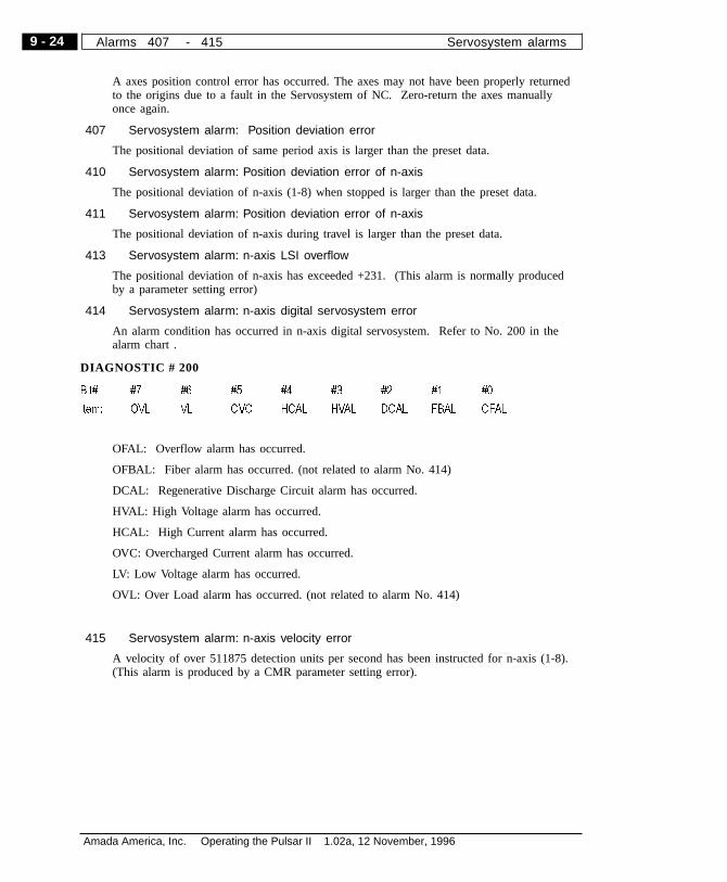
A axes position control error has occurred. The axes may not have been properly returnedto the origins due to a fault in the Servosystem of NC. Zero-return the axes manuallyonce again.
407 Servosystem alarm: Position deviation error
The positional deviation of same period axis is larger than the preset data.
410 Servosystem alarm: Position deviation error of n-axis
The positional deviation of n-axis (1-8) when stopped is larger than the preset data.
411 Servosystem alarm: Position deviation error of n-axis
The positional deviation of n-axis during travel is larger than the preset data.
413 Servosystem alarm: n-axis LSI overflow
The positional deviation of n-axis has exceeded +231. (This alarm is normally producedby a parameter setting error)
414 Servosystem alarm: n-axis digital servosystem error
An alarm condition has occurred in n-axis digital servosystem. Refer to No. 200 in thealarm chart .
415 Servosystem alarm: n-axis velocity error
A velocity of over 511875 detection units per second has been instructed for n-axis (1-8).(This alarm is produced by a CMR parameter setting error).
DIAGNOSTIC # 200
Bit# #7 #6 #5 #4 #3 #2 #1 #0
Item: OVL VL OVC HCAL HVAL DCAL FBAL OFAL
OFAL: Overflow alarm has occurred.
OFBAL: Fiber alarm has occurred. (not related to alarm No. 414)
DCAL: Regenerative Discharge Circuit alarm has occurred.
HVAL: High Voltage alarm has occurred.
HCAL: High Current alarm has occurred.
OVC: Overcharged Current alarm has occurred.
LV: Low Voltage alarm has occurred.
OVL: Over Load alarm has occurred. (not related to alarm No. 414)
9 - 24
Amada America, Inc. Operating the Pulsar II 1.02a, 12 November, 1996
Alarms 407 - 415 Servosystem alarms
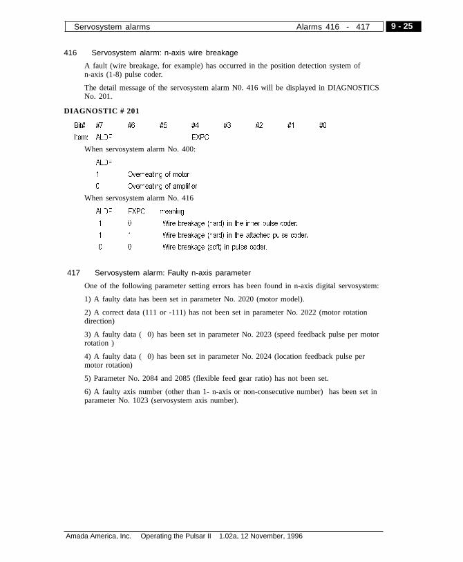
416 Servosystem alarm: n-axis wire breakage
A fault (wire breakage, for example) has occurred in the position detection system ofn-axis (1-8) pulse coder.
The detail message of the servosystem alarm N0. 416 will be displayed in DIAGNOSTICSNo. 201.
417 Servosystem alarm: Faulty n-axis parameter
One of the following parameter setting errors has been found in n-axis digital servosystem:
1) A faulty data has been set in parameter No. 2020 (motor model).
2) A correct data (111 or -111) has not been set in parameter No. 2022 (motor rotationdirection)
3) A faulty data ( 0) has been set in parameter No. 2023 (speed feedback pulse per motorrotation )
4) A faulty data ( 0) has been set in parameter No. 2024 (location feedback pulse permotor rotation)
5) Parameter No. 2084 and 2085 (flexible feed gear ratio) has not been set.
6) A faulty axis number (other than 1- n-axis or non-consecutive number) has been set inparameter No. 1023 (servosystem axis number).
DIAGNOSTIC # 201
Bit# #7 #6 #5 #4 #3 #2 #1 #0
Item: ALDF EXPC
When servosystem alarm No. 400:
ALDF
1 Overheating of motor
0 Overheating of amplifier
When servosystem alarm No. 416
ALDF EXPC meaning
1 0 Wire breakage (hard) in the inner pulse coder.
1 1 Wire breakage (hard) in the attached pulse coder.
0 0 Wire breakage (soft) in pulse coder.
9 - 25
Amada America, Inc. Operating the Pulsar II 1.02a, 12 November, 1996
Servosystem alarms Alarms 416 - 417

Overtravel alarms
• Overtravel alarms No. 504 and 505 occur only in type T.
500 Overtravel: +
axis (1-8) has traveled beyond the stored stroke limit I in the plus direction.
501 Overtravel: -
-nn-axis (1-8) has traveled beyond the stored stroke limit I in the minus direction.
502 Overtravel: +
axis (1-8) has traveled beyond the stored stroke limit II in the plus direction.
503 Overtravel: -
nn-axis (1-8) has traveled beyond the stored stroke limit II in the minus direction.
504 Overtravel: +
axis (1-8) has traveled beyond the stored stroke limit III in the plus direction.
505 Overtravel: -
axis (1-8) has traveled beyond the stored stroke limit III in the minus direction.
506 Overtravel: +
axis (1-8) has traveled beyond the hard OT in the plus direction.
507 Overtravel: -
axis (1-8) has traveled beyond the hard OT in the minus direction.
Overheat alarms
700 Overheat: control unit
The master printed circuit board is overheated.
704 Overheat: spindle
The spindle for main axis change detection is overheated.
(8) Spindle alarms
750 Main axis serial link start error
This alarm occurs when the main axis serial link unit of the system equipped with serialspindle does not start when the power is turned on. The following are the typical cases ofthis alarm:
1) Bad connection in lighting cable, or the power of the main axis control is not turned on.
2) NC power is turned on when the LED alarm display of the main axis control unit isother than SU-01 or AL-24.
3) Other (installation errors in the hardware)
9 - 26
Amada America, Inc. Operating the Pulsar II 1.02a, 12 November, 1996
Alarms 500 - 750 Overtravel alarms
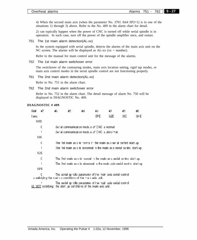
4) When the second main axis (when the parameter No. 3701 /bit4 SP2=1) is in one of thesituations 1) through 3) above. Refer to the No. 409 in the alarm chart for detail.
2) can typically happen when the power of CNC is turned off while serial spindle is inoperation. In such case, turn off the power of the spindle amplifier once, and restart.
751 The 1st main alarm detection(AL-xx)
In the system equipped with serial spindle, detects the alarms of the main axis unit on theNC screen. The alarms will be displayed as AL-xx (xx = number).
Refer to the manual for main control unit for the message of the alarms.
752 The 1st main alarm switchover error
The switchover of the contouring modes, main axis location setting, rigid tap modes, ormain axis control modes in the serial spindle control are not functioning properly.
761 The 2nd main alarm detection(AL-xx)
Refer to No. 751 in the alarm chart.
762 The 2nd main alarm switchover error
Refer to No. 752 in the alarm chart. The detail message of alarm No. 750 will bedisplayed in DIAGNOSTIC No. 409.
DIAGNOSTIC # 409
Bit# #7 #6 #5 #4 #3 #2 #1 #0
Item: SPE S2E SIE SHE
SHE
0 Serial communication module of CNC is normal.
1 Serial communication module of CNC is abnormal.
SIE
0 The 1st main axis is normal in the main axis serial control start up.
1 The 1st main axis is abnormal in the main axis serial control start up.
S2E
0 The 2nd main axis is normal in the main axis serial control start up.
1 The 2nd main axis is abnormal in the main axis serial control start up.
SPE
0 The serial spindle parameter of the main axis serial controlis satisfying the start up conditions of the main axis unit.
1 The serial spindle parameter of the main axis serial controlIS NOT satisfying the start up conditions of the main axis unit.
9 - 27
Amada America, Inc. Operating the Pulsar II 1.02a, 12 November, 1996
Overheat alarms Alarms 751 - 762

System alarms
900 ROM PARITY
A battery error in the ROM (CNC/OMM/Servosystem)
910 RAM PARITY : (4n)
A parity error has occurred in the RAM in the tape memory RAM module. Clear memoryor change the module.
911 RAM PARITY : (4N+1)
912 RAM PARITY : (4N+2)
913 RAM PARITY : (4N+3)
920 Servo Alarm (1/2 axis)
A watchdog alarm or RAM parity error in the servo module has occurred.
921 Servo Alarm (3/4 axis)
A watchdog alarm or RAM parity error in the servo module has occurred.
922 Servo Alarm (5/6 axis)
A watchdog alarm or RAM parity error in the servo module has occurred.
923 Servo Alarm (7/8 axis)
A watchdog alarm or RAM parity error in the servo module has occurred.
924 SERVO MODULE SETTING ERROR
Digital Servo module has not been installed.
930 CPU INTERRUPT
An abnormal interrupt error has occurred in the CPU.
945 SERIAL SPINDLE COMMUNICATION ERROR
A communication error has been found in the serial spindle. Breakage or omission of thelighting cable is a possible cause.
950 PMC SYSTEM ALARM
An error has occurred in the PMC.
951 PMC-RC WATCH DOG ALARM
An error has occurred in the PMC-RC. (A watchdog error)
970 NMI OCCURRED IN BOC
A RAM parity error or NMI has occurred in the PMC-RA2 or PMC-RB module.
971 NMI OCCURRED IN SLC
An LC communication error has occurred in the PMC-RA1or PMC-RA2.
972 NMI OCCURRED IN OTHER MODULE
NMI has occurred in a board other than main CPU board.
973 NON MASK INTERRUPT
An unidentified NMI has occurred.
9 - 28
Amada America, Inc. Operating the Pulsar II 1.02a, 12 November, 1996
Alarms 900 - 973 System alarms

Laser alarms
Contact Amada if any of the following alarms occur (except 670, 672, 673)
660 The allowance for clearence of Z-axis is excessive.
661 AD converter-1 irregularity
662 AD converter-2 irregularity
663 RF Power source problem
665 Shutter problem
666 Discharge tube problem
667 Resonator overtemp
669 Power Supply for laser interface PCB has problem
670 Chiller not ready
671 Low assist gas
672 low coolant flow rate - check chiller, filter, strainer
673 Laser gas pressure low. Check cylinder pressure
674 blower overtemp
675 cooling water too cold, condensation forming in RF power source
676 blower problem
677 beam dump absorber overtemp
678 discharge tube pressure abnormal
680 resonator vacuum leak
682 negative pressure sensor problem
683 A discharge tube is faulty, assist gas down, or shutter not open ??????
696 laser gas mixer overpressure
697 problem with gas mixer: bad power supply or mixer in E-stop condition or badinterface cable/connection.
698 gas mixer vacuum system problem
699 gas mixer pressure switch
4060 Large error of the following axis.
4061 An abnormal interrupt in A/D converter 1.
4062 An abnormal interrupt in A/D converter 2.
4063 Abnormal RF power.
4065 Abnormal shutter movement.
4066 A disconnected power discharge tube has been found.
4067 Temperature too high in the laser cabinet.
4068 Laser beam has been reflected back to the resonator.
9 - 29
Amada America, Inc. Operating the Pulsar II 1.02a, 12 November, 1996
Laser alarms Alarms 660 - 4068

4069 Abnormality in the power of laser IF has been found.
4070 Chiller is not ready.
4071 Assist gas is not ready.
4072 Cooling water too low.
4073 Mixed gas pressure too low.
4074 Root blower has been burning.
4075 Temperature of cooling water too low.
4076 Laser power too low.
4077 Beam absorber has been burning.
4078 Abnormal mix gas pressure in the power cable.
4079 EMERGENCY STOP button has been pressed. Reset the machine.
4080 A leak has been found in the power discharge tube or gas pipe.
4081 Gas pressure control is working yet the pressure is not properly controlledwithin the preset time period.
4082 Abnormality in the minus pressure sensor has been found.
4083 Shutter closed.
4084 Power source is not properly selected.
4085 Mirror is not clean.
4087 Shutter has been burning.
4088 Voltage in the power cable is getting low.
4089 Assist gas is not emitting.
4090 Laser is not working.
4091 Abnormality in the inverter has been found.
4094 Abnormality in the vacuum pump has been found
4095 Abnormality in the reading for the following displacement amount
9 - 30
Amada America, Inc. Operating the Pulsar II 1.02a, 12 November, 1996
Alarms 4069 - Laser alarms

AAlarm display
NC, program 9-3Aperture 1-3Approach data 7-15
BBattery, NC backup 8-15Blank
CRT screen 3-12, 7-3block skip
SEE Soft Switches
CCap sensor
nozzle 4-11, 8-11Cutting conditions
override 3-17, 3-19Cutting data
Create new file 7-33deleting 7-34editing 7-17make copy 7-34selecting from program 7-11selecting manually 7-16loading, saving 7-38
Cutting Data listingby material type 7-35
Cutting headidentification 4-10mounting 4-10
DDiagnostics
selecting screen 5-10
EEdge condition
editing 7-27Edge data 7-15
viewing 7-24
FFocus lens
adapter 4-12adjustment 8-21cleaning 4-10, 8-10identification 4-10
GGas selection 7-14
LLaser Status
Laser Power screen 5-18Lubrication 8-7
MMachine alarms
to display 9-3Material type
SEE Process categorymultiple part setup
SEE Soft Switches
NNozzle
centering 8-18inspection 8-11
OOptics
adjustment 8-16Overtravel
recovery 4-17
PParameters
selecting screen 5-10write enable 5-16
Parts countreset 5-9
Pierce
INDEX
10 - 1
Amada America, Inc. Operating the Pulsar II 1.02a, 12 November, 1996
Amada Laser Systems Index A - P

high-speed 7-20lead-in 7-24selecting manually 7-11
Process Category 7-10, 7-13Programming units
selecting Inch/mm 5-16
Rrapid override
SEE Soft SwitchesRelative coordinate system
preset 5-9Run time
reset 5-9
SSafety
Additional information 2-4Screen selection 5-4SETTING screen 5-16single block
SEE Soft SwitchesSoft Switches 3-22
UUnits of measure
SEE Programming units
WWork light 3-27
10 - 2
Amada America, Inc. Operating the Pulsar II 1.02a, 12 November, 1996
Index P - W Amada Laser Systems

Notes
10 - 3
Amada America, Inc. Operating the Pulsar II 1.02a, 12 November, 1996
Amada Laser Systems Index W - W

This page intentionally left blank

NOTE on internal Floppy Drive:
To assure that the system recognizes floppies in MS-DOS format, always have aformatted DOS floppy in place when powering the control up.
Also, when changing floppies, the system must read the disk directory before youcan access it. After closing the access door, either ( a) observe through the accessdoor that the indicating LED is ON, or (b) wait at least 10 seconds, before tryingto access the floppy.
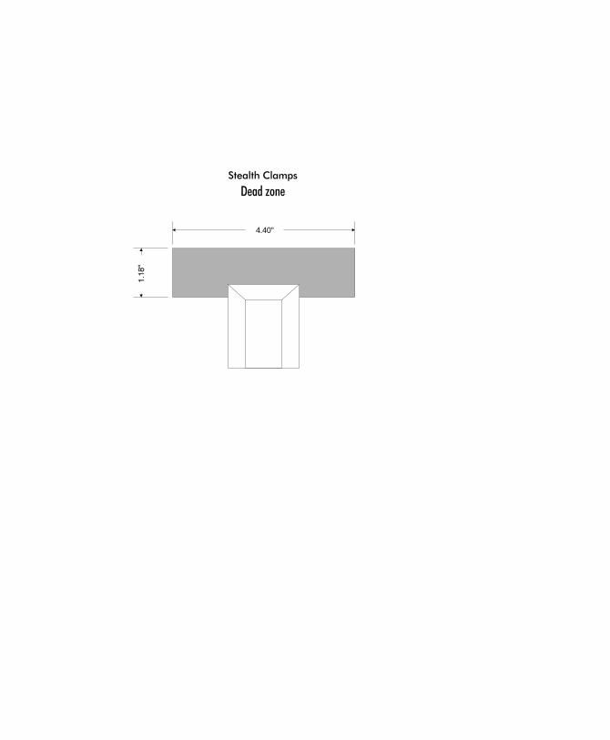
4.40"
Stealth Clamps
Dead zone