public improvements standards & specifications for …
TRANSCRIPT

PUBLIC IMPROVEMENTS STANDARDS &
SPECIFICATIONS
FOR THE TOWN OF RICHMOND
The Selectboard of Richmond hereby ordains the Public Improvements Standards & Specifications for the Town of Richmond. ADOPTED BY Richmond Selectboard on this 6th day of September, 2016 ________________ Ellen Kane, Chair ________________ Bard Hill, Vice Chair ________________ Lincoln Bressor ________________ Steven May ________________ David Sander Date of Public Hearing: September 6, 2016 Adoption Date: September 6, 2016 Effective date (60 days from adoption): November 5, 2016

2 0 1 6 T o w n o f R i c h m o n d P u b l i c I m p r o v e m e n t s S t a n d a r d s & S p e c i f i c a t i o n s
Page 1 of 45 2016 Richmond Town Public Improvements Standards and Specifications
TABLE OF CONTENTS
INTRODUCTION & APPROVAL PROCEDURE
1. Planning and Design Standards for
Streets, and Roads 1.1 Specific Standards for Streets & Roads 1.2 Village Street Design Standard 1.3 Access on to Roads and Street 1.4 Town Road and Bridge Standards 1.5 Rural Road Standards
2. Road and Street Construction Standards 2.1 General Construction Requirements 2.2 Excavation for Streets 2.3 Embankments 2.4 Ditches 2.5 Filter Fabric 2.6 Underdrains 2.7 Sand 2.8 Gravel Base 2.9 Crusher Run for Top Course 2.10 Stone Fill 2.11 Bituminous Concrete Pavement 2.12 Cement Concrete Curb 2.13 Cement Concrete Sidewalk 2.14 Cement Concrete Driveway Aprons 2.15 Bituminous Concrete Driveway Aprons 2.16 Street Sideline Monuments 2.17 Planting of Trees 2.18 Steel Guardrails 2.19 Roadway Name Signs 2.20 Other Roadway Signs 2.21 Roadway Lighting 2.22 Roadway Names 2.23 Posting of House Numbers 2.24 Landscaping
3. Storm Sewer & Stormwater Standards
3.1 Description
3.2 Materials 3.3 Size 3.4 Construction Methods 3.5 Treated Gutters 3.6 Stormwater Management & Best
Management Practices
4. Water Distribution Standards 4.1 Description 4.2 General Waterline Materials 4.3 Tapping Sleeves 4.4 Water Service Connection 4.5 General Construction Methods
5. Sanitary Sewer Standards 5.1 Description 5.2 Materials 5.3 Construction Methods
6. Other Infrastructure and Design Concepts
6.1 Bicycle, Pedestrian and Recreation Paths
6.2 Street Trees 6.3 Lighting Design - Roadway 6.4 Landscaping - Roadway 6.5 Bridges 6.6 Access Management 6.7 Buried Cables 6.8 ADA and Variances 6.9 Other Resources
List of Figures Appendices
2 0 1 6 T o w n o f R i c h m o n d P u b l i c I m p r o v e m e n t s S t a n d a r d s & S p e c i f i c a t i o n s
Page 2 of 45 2016 Richmond Town Public Improvements Standards and Specifications
INTRODUCTION
Public Works Specifications were first adopted in 1990 by the Town and Village of Richmond, Vermont. Several modifications were made to those standards over the years. The 2015 Town of Richmond Improvements Standards & Specifications represents a significant modification to 1990 Public Works Specifications. This set of standards and specifications applies to any new construction and reconstruction of public and private roads and streets, public storm water infrastructure, and water distribution and sanitary sewer lines connected to the municipal system due to obsolescence or deterioration of facilities. Variations from these standards and specifications shall not be permitted unless written supplemental specifications or special provisions for a given project are presented and approved in writing by the Town of Richmond. In such cases, the latest design methods shall be used and included on the plans for acceptance by the Town of Richmond. All plans and specifications shall have a note stating, “All work to be performed in accordance with the Town of Richmond Public Improvements Standards & Specifications.” The Town of Richmond has incorporated specific tables from the State of Vermont Agency of Transportation Standard Specifications for Construction, which is adopted as a supplemental source for standards not specifically referenced within the Town of Richmond Public Improvements Standards and Specifications. All materials, design, and work products must meet nationally accepted standards and practices, along with all applicable standards of the Town of Richmond, including these Town of Richmond Public Improvements Standards & Specifications, the Richmond Zoning Regulations, and the Richmond Subdivision Regulations (latest edition of each document). The Town of Richmond wishes to acknowledge Justin Willis of Willis Design Associates Inc. for his contributions toward this document, specifically for preparing Figure 1 through Figure 22, and to former Town Planner Cathleen Gent for coordinating the update effort.
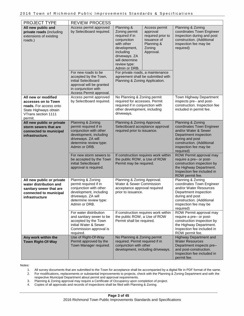
APPROVAL PROCEDURE Dependent on the nature of the project, one or more approval procedures maybe required for a project. Subsequent modifications to approved plans must be reviewed and approved by the Town. Violations of these Public Improvements Standards and Specifications maybe subject to legal remedies provided by law. Please refer to the following flow chart for an overview of the applicable processes:
2 0 1 6 T o w n o f R i c h m o n d P u b l i c I m p r o v e m e n t s S t a n d a r d s & S p e c i f i c a t i o n s
Page 3 of 45 2016 Richmond Town Public Improvements Standards and Specifications
PROJECT TYPE REVIEW PROCESS All new public and
private roads (including extensions of existing roads.)
Access permit approved by Selectboard required.
Planning & Zoning permit required if in conjunction with other development, including driveways. ZA will determine review type: Admin or DRB.
Access permit approval required prior to issuance of Planning & Zoning Approval.
Planning & Zoning coordinates Town Engineer inspection during and post construction. (Additional inspection fee may be required)
For new roads to be accepted by the Town, initial Selectboard approval will be granted in conjunction with Access Permit approval.
For private roads, a maintenance agreement shall be submitted with Planning & Zoning Application.
All new or modified
accesses on to Town
roads. For access onto State Highways obtain VTrans section 1111 permit.
Access permit approved by Selectboard required.
No Planning & Zoning permit required for accesses. Permit required if in conjunction with other development, including driveways.
Town Highway Department inspects pre– and post-construction. Inspection fee included in permit fee.
All new public or private
storm sewers that are
connected to municipal
infrastructure.
Planning & Zoning permit required if in conjunction with other development, including driveways. ZA will determine review type: Admin or DRB.
Planning & Zoning Approval. Selectboard acceptance approval required prior to issuance.
Planning & Zoning coordinates Town Engineer and/or Water & Sewer Department inspection during and post construction. (Additional inspection fee may be required)
For new storm sewers to be accepted by the Town initial Selectboard approval is required.
If construction requires work within the public ROW, a Use of ROW Permit may be required.
ROW Permit approval may require a pre– or post-construction inspection by the Highway Department. Inspection fee included in ROW permit fee.
All new public or private
water distribution and
sanitary sewer that are
connected to municipal
infrastructure
Planning & Zoning permit required if in conjunction with other development, including driveways. ZA will determine review type: Admin or DRB.
Planning & Zoning Approval. Water & Sewer Commission acceptance approval required prior to issuance.
Planning & Zoning coordinates Town Engineer and/or Water Resources Department inspection during and post construction. (Additional inspection fee may be required)
For water distribution and sanitary sewer to be accepted by the Town initial Water & Sewer Commission approval is required.
If construction requires work within the public ROW, a Use of ROW Permit shall be required.
ROW Permit approval may require a pre– or post-construction inspection by the Highway Department. Inspection fee included in ROW permit fee.
Any work within the
Town Right-Of-Way
Use of Right-Of-Way Permit approved by the Town Manager required.
No Planning & Zoning permit required. Permit required if in conjunction with other development, including driveways.
Highway Department and Water Resources Department inspects pre– and post-construction. Inspection fee included in permit fee.
Notes:
1. All survey documents that are submitted to the Town for acceptance shall be accompanied by a digital file in PDF format of the same.
2. For modifications, replacements or substantial improvements to projects, check with the Planning & Zoning Department and with the respective Municipal Department about permit and approval requirements.
3. Planning & Zoning approval may require a Certificate of Occupancy upon completion of project. 4. Copies of all approvals and records of inspections shall be filed with Planning & Zoning.

2 0 1 6 T o w n o f R i c h m o n d P u b l i c I m p r o v e m e n t s S t a n d a r d s & S p e c i f i c a t i o n s
Page 4 of 45 2016 Richmond Town Public Improvements Standards and Specifications
1. PLANNING AND DESIGN STANDARDS FOR STREETS and ROADS All vehicular traveled ways in the Town of Richmond can be classified according to one of several categories. First, all roadways are either public or private. All private roadways shall be developed to the same standards as public roadways; however, certain roads may be approved as Rural Roads (see Section 1.5). Also, if approved by the DRB, a private roadway may have a gravel surface. If a private roadway is approved as gravel and it intersects a paved roadway, the private roadway shall also be paved to a point 30’ from the centerline of the paved roadway. Second, all vehicular traveled ways are classified by use and location as streets, roads or driveways. For driveway standards refer to the Richmond Zoning Regulations. Streets are generally low speed, urban or village area thoroughfares used for access to residential or commercial properties and are further divided into three sub-classifications of no on-street parking, parking on one side, and parking on both sides. See Table 1 for design parameters. Within the former Village of Richmond boundary area, new subdivisions and new streets will follow the “Village Design Standard” in Section 1.2, below. Roads are low to moderate speed thoroughfares which provide access to residential properties, provide connections between other local roads or provide connections between communities. Roads are divided into the sub-classifications of local roads (or Class 3 roads) and collector roads (or Class 2 roads). Local roads will fall into either the category of average daily traffic (ADT) of 31 – 100 (Local Road – Minor) or ADT of 101 and above (Local Road - Major). Table 1 provides additional clarification. The standards listed here are considered minimum and apply to construction projects and maintenance and repair activities. The standards include best management practices and are intended to: 1) ensure the safety of the travelling public; 2) minimize damage to road infrastructure during flood events; and 3) enhance water quality protection by minimizing sediment delivery to surface waters and wetlands. The Selectboard reserves the right to modify the standards for a particular project or repair/maintenance activity where, because of unique physical conditions, there is no possibility that the activity can be completed in strict conformance with these provisions. Any modifications to the standards must be done in a manner that serves the underlying purposes as stated above. Fiscal reasons shall not be considered as the basis for modification of the standards.
1.1 SPECIFIC STANDARDS FOR STREETS AND ROADS Table 1, Summary of Roadway Design Standards, has been added to supplement the following discussion of design parameters.

2 0 1 6 T o w n o f R i c h m o n d P u b l i c I m p r o v e m e n t s S t a n d a r d s & S p e c i f i c a t i o n s
Page 5 of 45 2016 Richmond Town Public Improvements Standards and Specifications
TABLE 1
SUMMARY OF ROADWAY DESIGN STANDARDS
CATEGORY RIGHT OF
WAY
TRAVEL WIDTH
SHOULDER WIDTH
APPROACH DISTANCE OF 3% AT
INTERSEC- TIONS
MAXIMUM GRADE
MIN. RADIUS
MINIMUM STOPPING
SIGHT DISTANCE
CURB SIDE-WALK
PAVE-MENT
NOTES
STREETS 4, 5, 8
No parking 60’ 18’ 0’ 50’ 10% 150’ 150’ Yes Yes Yes 3
Park 1 side 60’ 26’ 0’ 50’ 10% 150’ 150’ Yes Yes Yes 3
Park 2 side 60’ 34’ 0’ 50’ 10% 150’ 150’ Yes Yes Yes 1, 3
ROADS 4, 5, 8
Local – Minor 8
AADT 31-100 60’ 20’ 2’ 50’ 10% 150’ 150’ No No Yes 2
Local – Major
AADT 101 + 60’ 22’ 2’ 50’ 10% 150’ 200’ No No Yes 2
Collector
Class 2 60’ 24’ 2’ 100’ 10% 250’ 325’ No No Yes 2
Commercial 60’ 20’ to 36’ 2’ 50’ 10% 150’ 150’ No No Yes 2
NOTES: 1. Streets with parking on both sides will have sidewalks on both sides, unless otherwise approved by the DRB 2. Roads will not include sidewalks unless required by the DRB 3. Street travel lane widths shall be 9’ and parking lane widths shall be 8’. Widths shown in travel width column include
parking. 4. A private road may be gravel if so approved. If it intersects a paved road, the private road shall be paved for a
distance of 30’ from the centerline of the paved road. 5. The 3% approach grade distance at a road intersection shall be measured from the centerline of the existing road to
the PVC or PVT (whichever is closer) of the nearest vertical curve on the intersecting road. 6. The 3% approach grade distance at a driveway intersection shall be measured from the edge of the shoulder of the
existing road to the first PVI on the driveway. 7. All single family detached residences are defined as generating 10.0 vehicle trips per day. Trip generation for all other
land uses shall be as presented in the latest edition of Trip Generation by the Institute of Traffic Engineers (ITE). 8. Right-of-way and easement widths may be increased when necessary to accommodate proposed and future potential
infrastructure needs.
Additional notes in regard to design standards for roadways
All new proposed streets, roads, driveways, utilities, and other public or private improvements shall be designed and constructed in accordance with these standards. The minimum width of road or street rights-of-way, measured from property line to property line, shall not be less than 60'. Maximum roadway or street grades shall not exceed 10%. The minimum grade shall not be less than 0.5%. The maximum grades near the intersection of two roads or streets shall not be greater than 3% for a distance as specified in Table 1. The widths of the traveled way and shoulders of any road or street shall be as given in Table 1. If sidewalks and/or bike paths are required in new developments, the minimum widths shall be 5’ and 8’ respectively. Eight foot is the minimum for low use paths, 10ft is the preferred minimum width, and 12ft+ for higher use facilities. Replacement of existing bridges and any new bridges must be designed in accordance with the VTrans Hydraulic Manual and shall be wide enough to accept 2 lanes equal in width to the road lanes and shoulders as called for in Table 1. The hydraulic capacity of all bridges shall meet or exceed that required for a 25 year storm. Except at an intersection, any street lines deflecting from each other at any point shall be connected with a curve, the radius of which, at the centerline, shall not be less than the value

2 0 1 6 T o w n o f R i c h m o n d P u b l i c I m p r o v e m e n t s S t a n d a r d s & S p e c i f i c a t i o n s
Page 6 of 45 2016 Richmond Town Public Improvements Standards and Specifications
given in Table 1. Intersection corners of streets or local roads and residential driveways shall have a minimum curb or edge of pavement radius of not less than 20'. Collector road and commercial drive intersections shall have a minimum curb or edge of pavement radius of not less than 30'. Every change in grade shall be connected by a vertical curve designed to afford a minimum sight distance no less than the value given in Table 1. A tangent of at least 100’ in length shall be introduced between reverse curves on all proposed streets. If at all possible, the use of compound curves shall be avoided; however, if topography constraints dictate their use, the radius of the flatter curve shall not exceed the radius of the sharper curve by more than 50%. The broken back arrangement of curves (a short tangent between two curves in the same direction) shall be avoided by ensuring that any intermediate tangent be no less than 100’ in length. Roadway intersections not located directly across from each other with centerline offsets of less than 200' shall not be allowed. Intersections shall be at right angles, unless agreed to by the Town, and no intersection shall be at an angle of less than 80 degrees. All dead-end roads or streets shall have a cul-de-sac or other approved turn-around. The number of dwelling units served by a cul-de-sac or by a system of streets sharing a common, single access shall not exceed 50 unless additional connections to other streets are approved by the DRB. Long dead end roads shall have intermediate half-circle cul-de-sacs every 2000’. A cul-de-sac shall have a minimum diameter of right-of-way of 120’ and a minimum outside diameter of traveled way of 100'. If a cul-de-sac is not feasible, the use of other types of turnarounds will be reviewed by the Selectboard. One such alternative is the “hammerhead” turn-around. Both legs of any hammerhead shall extend a minimum of 50’ from the centerline intersection of those legs. Where a new subdivision borders on an existing road or an abutting developable parcel of land and when the Town determines that a realignment or widening of the road or a future road right-of-way would be in the public interest, the Town may require that such areas be shown and marked on the Plat "Reserved for Road Alignment and/or Widening Purposes” or “Future Road". Areas shown in this manner shall be dedicated to the Town through the applicant/developers “Offer of Dedication” for such areas and any infrastructure improvements to be installed by the application/developer as part of the local permit review or road acceptance process. The Offer of Dedication must recorded in the Richmond Land Records prior to any construction activity commencing where such construction activity is in anyway related to the authorized by the Town. Corner sight distances at intersections of drives, roads or streets with other roads or streets shall be as follows:
TABLE 2
CORNER SIGHT DISTANCES
If the main road has no posted speed limit, use the following:
CATEGORY OF MAIN ROAD REQUIRED CORNER SIGHT DISTANCE
Local 385’
Collector 385’
Street 275’

2 0 1 6 T o w n o f R i c h m o n d P u b l i c I m p r o v e m e n t s S t a n d a r d s & S p e c i f i c a t i o n s
Page 7 of 45 2016 Richmond Town Public Improvements Standards and Specifications
If the main road has a posted speed limit, use the following:
POSTED SPEED LIMIT REQUIRED CORNER SIGHT DISTANCE
Less than 30 275’
30 330’
35 385’
40 440’
45 495’
50 550’
Corner sight distance is measured from a point on the intersecting roadway which is 15’ behind the edge of traveled way. The height of the eye is 3.5’ on the intersecting roadway and the height of the object is 4.25’ on the main roadway.
1.2 VILLAGE STREET DESIGN STANDARD For new subdivisions or new streets constructed within the boundaries of the former Village of Richmond, the street design shall consist of the following concepts:
All streets shall be curbed on both sides Width shall be determined according to the parking scheme for the street (See Table 1) All streets shall be paved, regardless of whether they are public or private Historic street lights shall be incorporated into the design Sidewalks shall be constructed on one or both sides of the street Storm drainage shall be subsurface with pipes and catch basins Bike facilities shall be incorporated into the design (such as bike path, bike lane, bike rack
or other appropriate facility)
1.3 ACCESS ON TO ROADS AND STREETS
A property owner must apply for an access permit (or amendment) for any new access on to a road or street, such as for a new road or driveway (or for any new uses that increase the ADT for the driveway). See Section 6.6 Access Management for additional requirements and information.
1.4 TOWN ROAD AND BRIDGE STANDARDS The “Town Road and Bridge Standards, Town of Richmond Vermont,” which was adopted by the Richmond Selectboard in February 2013, has been incorporated within this document with respect to all construction projects as well as repair and maintenance activities for roads, ditches and slopes, culverts, bridges, and guardrails for public and private roads and infrastructure facilities.
1.5 RURAL ROAD STANDARDS The “Policy and Guidelines Related to Rural Road Specifications and Standards” may apply, in certain types of low-density development in rural areas. See Appendix 1. The Rural Road Policy is designed to apply to the following single-family residential developments in the Town of Richmond: 1. Those single-family dwelling unit subdivisions (single-family meaning to include up to one accessory apartment in conformance with applicable regulations) consisting of four to nine residential lots that use a single shared access to a town road. 2. Those within the Agricultural/Residential Zoning District or in an area of town where by deed or physical limitations shall remain a low-density area (low-density meaning less than one single-family housing unit within a 500 foot radius of any other existing or proposed house or nonresidential structure, such as a store, business office or similar primary use of a parcel).
2 0 1 6 T o w n o f R i c h m o n d P u b l i c I m p r o v e m e n t s S t a n d a r d s & S p e c i f i c a t i o n s
Page 8 of 45 2016 Richmond Town Public Improvements Standards and Specifications
3. Those subdivisions which have an expressed written goal to preserve the rural atmosphere of the development and the surrounding area.
All larger subdivisions will be required to meet the Public Improvements Standards and Specifications. A subdivision of 3 or less residential units are required to meet the driveway requirements as provided in the Richmond Zoning Regulations and to provide safe access for emergency vehicles. By reference, the “Policy and Guidelines Related to Rural Road Specifications and Standards”, adopted, are hereby incorporated into this document.

2 0 1 6 T o w n o f R i c h m o n d P u b l i c I m p r o v e m e n t s S t a n d a r d s & S p e c i f i c a t i o n s
Page 9 of 45 2016 Richmond Town Public Improvements Standards and Specifications
2. ROAD AND STREET CONSTRUCTION STANDARDS
This section contains information regarding the methods and materials required in the construction of roads and streets in the Town of Richmond for new development projects as well as to the rehabilitation or reconstruction of existing roads or streets. Refer to Figures 1 – 11. The Standard Section shall be followed unless it is proved to the Town by observation of a suitable number of test pits, that the Special Section is adequate.
2.1 GENERAL CONSTRUCTION REQUIREMENTS
All materials, design, and workmanship must meet with nationally accepted standards and practices and, when applicable, to those of the State or Town. For roads and streets to be accepted by the Town, the Selectboard will require that a professional engineer stamp the proposed plans to certify that the plans are in compliance with professional engineering standards. An As-Built Drawing may be required on all major construction properties, especially when new right-of-ways are established for either private or public investments. Poles, brackets, and lights for street lighting are to be approved as to size, type, and location by the Town. They shall be complete and fully energized prior to acceptance of the street by the Town. Any excavation made through any portion of an existing Town road shall be approved by the Town Road Foreman in advance and shall be returned to original or better condition within one week of the initial cut. Restored road cuts shall be guaranteed by the applicant for a period of one year. Any such activity shall be applied for by submittal of the Richmond Use of Town ROW form to the Road Foreman. All of the public improvements to be dedicated to the Town of Richmond shall be guaranteed by a bond, or other surety, provided to the Town at no cost. The bond, or other surety, shall be in an amount sufficient to cover the total estimated costs of the improvements as approved by the Town and shall be conditioned upon the satisfactory condition of the improvements for a period of three years from the date of final acceptance by the Selectboard . Before the bond is set, a "Project Cost Estimate Form" shall be completed and submitted to the Town. Also, if the bond value or surety amount is to be reduced as the investment is completed, that schedule shall also be determined prior to the commencement of construction. For new subdivisions, the DRB may impose surety requirements, as regulated in the Richmond Subdivision Regulations. The workers and the public shall be protected by the Contractor from any and all hazards connected with the construction work. Open trenches, materials, or equipment within the working limits are to be guarded by the use of adequate barricades or flagmen. All barricades left in position overnight are to be properly lighted. When work narrows the traveled portion of pavement, flagmen shall be employed to aid the flow of traffic so that there will be no undue delays.
The Contractor shall be held responsible for the safety of all workers and the general public and for all damages to property occurring from or upon the work occasioned by negligence or otherwise growing out of a failure on the part of the Contractor to protect persons or property from hazard of open trenches, materials, or equipment at any time of the day or night within the working area. All work shall be in conformance with all applicable OSHA and VOSHA regulations. Construction approach signs shall appear at each end of the highway under construction and on all intersecting public highways. The exact placement of any sign will depend upon the alignment of the highway and the character of the roadsides. The location, measurements, and minimum spacing is to be observed by the Town in determining exact locations.

2 0 1 6 T o w n o f R i c h m o n d P u b l i c I m p r o v e m e n t s S t a n d a r d s & S p e c i f i c a t i o n s
Page 10 of 45 2016 Richmond Town Public Improvements Standards and Specifications
The design of the signs shall conform with the standards prescribed in the most recent edition of the Manual on Uniform Traffic Control Devices prepared by the National Joint Committee on Uniform Traffic Control Devices. The signs shall be of metal, wood, plywood, hardboard, or any other material satisfactory to the Town. No material shall be approved that will deteriorate by exposure to the weather during the required life of the sign. The signs shall be in place at the time the project officially commences. Each sign shall be erected in a neat and workmanlike manner on wood or metal posts set securely in the ground.
2.2 EXCAVATION FOR STREETS
All topsoil shall be stripped from areas to be filled or excavated and sufficient topsoil shall be saved to provide a minimum of 4" of cover over all finished slopes. This material shall be stored in stockpiles on the site until completion of grading operations and then shall be spread uniformly over all finished slopes. All excavating and filling required for construction of pavements, curbs, gutters, headwalls, drainage structures, and installation of pipe drains shall be as specified herein and shown on the construction standards. The entire area of work shall be brought to the required lines and grades by excavation or filling. Excavated material, if suitable, shall be used in making embankments, in filling the low areas of work, and at such places as may be required. All earthwork shall be performed in accordance with Division 200 of the Vermont Standard Specifications for Construction. Rock excavation consists of removal and disposal of material encountered that cannot be excavated without continuous and systematic drilling and blasting or continuous use of a ripper or other specialized equipment. Explosives to be used in excavation of rock shall not be brought onto the site without prior notification of the Town. The Contractor is solely responsible for handling, storing, and using the explosives and shall comply with all ordinances, rules, regulations and standards of safety.
2.3 EMBANKMENTS
Embankments shall be constructed by the Contractor with either approved surplus excavated material or with approved material obtained elsewhere. All material resulting from clearing and grubbing shall be satisfactorily disposed of in a manner approved by the Town and in compliance with local and State ordinances. Under no conditions will this material be buried below the seasonal high groundwater. When embankments are to be made on a hillside, the slope of the original ground on which the embankments are to be constructed shall be stepped and properly drained as the fill is constructed so that adverse movements of the slopes do not occur. Grassed side slopes in roadway cuts or embankments shall descend no steeper than 1' vertically for 2’ horizontally (1 on 2). In cases of severe topographic constraint, slopes may be as steep as 1 on 1.5; however, they shall be stabilized with 18” of Type 2 rock protection. Rock cuts shall ascend no steeper than 6' vertically for each 1' horizontally (6 on 1). Where rock cuts have a face higher than 10' vertically, a 3' bench shall be provided at each 10' level above the grade at the edge of the pavement. The excavated rock, ledge, boulders, and stone, except where required in the construction of
2 0 1 6 T o w n o f R i c h m o n d P u b l i c I m p r o v e m e n t s S t a n d a r d s & S p e c i f i c a t i o n s
Page 11 of 45 2016 Richmond Town Public Improvements Standards and Specifications
other items or otherwise directed, shall be used in the construction of embankments to the extent of the project requirements and generally shall be placed so as to form the base of an embankment.
Frozen material shall not be used in the construction of embankments, nor shall the embankments or successive layers of the embankments be placed upon frozen material. Placement of material other than rock shall stop when the sustained air temperature, below 32 degrees Fahrenheit, prohibits the obtaining of the required compaction. If the material is otherwise acceptable, it shall be stockpiled and reserved for future use when its condition is acceptable for use in embankments. When an embankment is to be constructed across a swamp , muck, or areas of unstable soils, the unsuitable materials shall be excavated to reach soils of adequate bearing capacity and the embankment begun. Alternative methods, such as use of a filter fabric in place of excavation and backfill, may be utilized only after approval of same by the Town. Material being placed in embankments shall be placed in horizontal layers of uniform thickness across the full width of the embankment. Stumps, trees, rubbish, and other unsuitable material shall not be placed in embankments. The layers shall begin at the deepest part of the fill. Material shall be placed in 6" lifts with a 95 percent maximum dry density by the AASHTO-T-99, Method A (Standard Proctor) test. Effective spreading equipment shall be used on each layer to obtain uniform thickness prior to compaction. Each layer shall be kept crowned to shed water to the outside edge of the embankment and continuous leveling and manipulating will be required to assure uniform density. The entire area of each layer shall be uniformly compacted to at least the required minimum density by use of compaction equipment consisting of rollers, compactors, or a combination thereof. Earthmoving and other equipment not specifically manufactured for compaction purposes will not be considered as compaction equipment. All fill material shall be compacted at a moisture content suitable for obtaining the required density. In no case shall the moisture content in each layer under construction be more than three percent above the optimum moisture content and shall be less than that quantity that will cause the embankment to become unstable during compaction. Sponginess, shoving, or other facie evidence shall constitute an engineering determination of lack of stability under this requirement, and further placement of material in the area affected shall be stopped or retarded to allow the material to stabilize.
When the moisture content of the material in the layer under construction is less than the amount necessary to obtain satisfactory compaction by mechanical compaction methods, water shall be added by pressure distributors or other approved equipment. Water may also be added in excavation or borrow pits. The water shall be uniformly and thoroughly incorporated into the soil by disc harrowing, blading, or by other approved methods. The manipulation may be omitted for sands and gravel. When the moisture content of the material is in excess of three percent above the optimum moisture content, dry material shall be thoroughly incorporated into the wet material, or the wet material shall be aerated by disking, harrowing, blading, rotary mixing, or by other approved methods. Compaction of the layer of wet material shall be deferred until the layer has dried to the required moisture content by evaporation. Upon completion of filling and excavating, the subgrade shall be formed to the required grade and contour; and the entire surface again rolled as specified above. High spots shall be removed and low spots filled with acceptable material, and the process of leveling and rolling continued until no further depression results. Approval of the Town shall be necessary prior to placing of gravel
2 0 1 6 T o w n o f R i c h m o n d P u b l i c I m p r o v e m e n t s S t a n d a r d s & S p e c i f i c a t i o n s
Page 12 of 45 2016 Richmond Town Public Improvements Standards and Specifications
bottom course.
2.4 DITCHES
Soil exposed during ditch and slope construction, repair or maintenance must be treated immediately following the operation and temporary erosion and sediment control practices must be installed and maintained during construction activities and until the ditch or slope is permanently stabilized. The following are minimum erosion control measures. Careful attention must be given to areas vulnerable to erosion and immediately adjacent to surface water and/or roadway drainage facilities:
Seed and mulch all ditches with grades less than 5%. Vegetation must be established and monitored. If vegetation is not established within 10 days, install biodegradable non-welded matting with seed.
Stone line all ditches with grades equal to and greater than 5%. Alternately, install stone check dams in conformance with Standards and Specifications for Check Dams from the Vermont Standards and Specifications for Erosion Prevention and Sediment Control. Specifically, dams must be placed so the crest of the downstream dam is at the same elevation as the base of the upstream dam.
Create parabolic (wide, U-shaped) ditches rather than narrow V-shaped ditches where ever space allows. Preferable are ditches with gradual (max 1:2) side slopes and wide (2’ minimum) bottoms. Use biodegradable, non-welded matting to stabilize side slopes where slopes are greater than 1:2 and less than 1:1 ½; use seed and mulch on slopes less than 1:2.
Strive to create a vegetated or rock lined filter area at the outlet of all ditches prior to discharge to any surface water.
When constructing new or substantially reconstructed side slopes, use appropriately sized stone armament on slopes greater than 1:1 ½. If perennial streams are effected by the toe of slope, the project must conform to Vermont Stream Alteration standards.
An alternate ditch treatment may be employed by the Town for a maintenance or repair project if such alternate is reviewed and approved in writing by the Vtrans Operations Division.
2.5 FILTER FABRIC
Where required on the plans or where directed by the Town, the Contractor shall install filter fabric, such as Mirafi 500X as manufactured by Celanese Corporation, or an approved equal, over the subgrade prior to placement of the road base. Mirafi 140N, or equal, shall be placed around drains. Prior to placement of the filter fabric, the surface shall be smoothed to remove all objectionable material, which could damage the fabric. Where more than one width of filter fabric must be employed, the edges shall be overlapped 2' and affixed to the ground surface with 6" minimum U-shaped wire pins, single-shaft steel pins with metal disc fasteners, or similar devices. Fasteners should be placed 6’ apart on the overlap. Where utilized in underdrains, channels, or streams, the fabric should be overlapped in the direction of water flow. Toeing may be required to ensure that the fabric is not undermined by water flow. Unless otherwise approved, construction of all roadways, except private driveways shall include appropriate filter fabric over the subgrade, directly beneath the subbase.
2.6 UNDERDRAINS

2 0 1 6 T o w n o f R i c h m o n d P u b l i c I m p r o v e m e n t s S t a n d a r d s & S p e c i f i c a t i o n s
Page 13 of 45 2016 Richmond Town Public Improvements Standards and Specifications
A. Description: This item shall consist of constructing underdrains using pipe, stone, filter fabric, underdrain outlets, clean outs and risers in accordance with these specifications and as shown on the accepted drawings or as ordered by the Town. Underdrain shall be designed in accordance with VTrans Standards B-11 and D-30.
B. Materials:
Perforated Polyvinyl Chloride (PVC): PVC SDR 35 pipe shall conform to ASTM F75B or AASHTO, M278.
Perforated Corrugated Steel Pipe: Pipe shall conform to AASHTO, M36. Minimum sheet metal thickness required is 0.052 inch for six inch diameter underdrain and 0.064 inch for eight inch diameter or larger.
Perforated Corrugated Aluminum Alloy Pipe: Pipe shall conform to AASHTO, M196. Perforated High Density Polyethylene Pipe shall conform to AASHTO, M252. Stone: Stone fill shall be clean, durable, ¾" to 1 ½" stone. Filter Fabric: The fabric shall be Mirafi 140N or equal.
C. Construction Methods:
Trenches for underdrain shall be excavated to the dimensions and grade shown on the plans or as ordered by the Town. Stone fill shall be placed to a depth of 6" below the bottom of the pipe in conformity with the lines and grades shown on the plans or as directed by the Town. Underdrain shall be placed in the center of the trench and firmly embedded in the material. The underdrain trench shall be backfilled to the gravel road base with 3/4" to 1 1/2" clean stone. Placing shall begin at the outlet end and proceed toward the upper end. The underdrain shall be placed with perforations down unless otherwise ordered by the Town. The joints between sections shall be made by fitting the ends as tightly as practicable. Corrugated steel or aluminum alloy underdrain shall be joined with an approved coupling. PVC and HDPE plastic underdrain shall be suitably joined with approved fittings by the same manufacturer. Upgrade ends of all underdrain pipe installations shall be closed with suitable plugs to prevent entry of soil material. Underdrain cleanouts of the length shown on the plans and cast iron covers shall be installed at locations shown on the plans or as directed by the Town. Pipes used in an underdrain system placed at road crossings, outlets, or as directed by the Town shall be placed on a firm bed and joined in the same manner as underdrain. Unless otherwise directed, non-perforated pipe shall be used. Backfill material shall not be placed directly in the trench by dumping from haul vehicles or by pushing material into trenches by bulldozers, graders, or other equipment. Placing shall be limited to the use of hand shovels, backhoes, front-end loaders, or other similar types of equipment. Filter fabric shall be placed in the trench around the stone fill with a 6" fabric overlap at the top.
2.7 SAND
A. Description: This item shall consist of a subbase course of sand as approved by the Town and constructed on a prepared subgrade in accordance with the sections as shown on the accepted drawings.

2 0 1 6 T o w n o f R i c h m o n d P u b l i c I m p r o v e m e n t s S t a n d a r d s & S p e c i f i c a t i o n s
Page 14 of 45 2016 Richmond Town Public Improvements Standards and Specifications
B. Materials:
Sand shall consist of material free from silt, loam, clay, or organic matter. It shall conform to the Vermont Standard Specifications for Construction for Sand Borrow, # 703.03. It shall be obtained from approved sources and shall meet the requirements set forth in this table:
Percentage By Weight
Sieve Designation Passing Square Mesh Sieve
2" 100 1 1/2" 90 - 100 1/2" 70 - 100 No. 4 60 - 100 No. 100 0 - 20 No. 200 0 - 6
2.8 GRAVEL BASE
A. Description: This item shall consist of a base course composed of bank run gravel and approved by the Town and constructed on a prepared subgrade in accordance with the sections as shown on the accepted drawings.
B. Materials:
Materials shall be secured from approved sources. Such gravel shall consist of hard, durable stones, which show uniform resistance to abrasion and which are intermixed with sand or other approved binding material as directed by the Town. It shall meet the requirements of Vermont Standard Specification for Construction, #704.04, Gravel for Subbase.
The gravel shall be uniform in grade from course to fine and shall meet the grading requirements set forth in this table:
Percentage By Weight
Sieve Designation Passing Square Mesh Sieve Total Sample Sand Portion
No. 4 20 – 60 100 No. 100 0 – 12 No. 200 0 – 6
All bottom course material shall be deposited and spread so as to distribute the material in uniform layers, compacted at optimum moisture content; and the maximum size stone particles shall not exceed 2/3 of the thickness of the layer being placed.
C. Preparation of Subbase:
The subbase material shall be placed on a prepared surface with an approved spreader box or by some other approved mechanical spreading equipment. The material shall be deposited so as to meet the requirements of the Vermont Standard Specifications for Construction, Section 301, and compacted to a 95 percent dry density by the AASHTO-T-99 Method A (Standard Proctor) test. If necessary where there is high ground water or frost susceptible soils, subbase fabric and underdrains shall be installed beneath the roadway as specified by the Town or as

2 0 1 6 T o w n o f R i c h m o n d P u b l i c I m p r o v e m e n t s S t a n d a r d s & S p e c i f i c a t i o n s
Page 15 of 45 2016 Richmond Town Public Improvements Standards and Specifications
shown on the street details of these specifications.
2.9 CRUSHER RUN TOP COURSE A. Description:
This item shall consist of an upper course of crusher run gravel to be placed over the bottom course of bank run gravel which will have been prepared in accordance with these specifications. This upper course shall conform to the following specifications and be placed in accordance with the lines, grades, and typical cross sections as shown on the accepted drawings. Material shall meet Vermont Standard Specifications for Construction, # 704.05, Crushed Gravel for Subbase.
B. Materials:
All materials shall be secured from approved sources. This gravel shall consist of angular and round fragments of hard durable rock of uniform quality throughout, reasonably free from thin elongated pieces, foreign matter, dirt or other objectionable matter. The grading requirement shall conform to the following table:
Percentage By Weight Sieve Designation Passing Square Mesh Sieve
2" 100 1 ½" 90 – 100 No. 4 30 – 60 No. 100 0 – 12 No. 200 0 – 6
C. Preparation of subbase
This upper course of crusher run gravel shall be deposited and spread in a uniform layer and compacted to 95 percent dry density by the AASHTO-T-99 Method A (Standard Proctor) test.
2.10 STONE FILL Stone fill shall meet the following grading requirements: Type 1 - Long dimension between 1” and 12” 50% of volume of stone in place shall have a least dimension of 4” Type 2 - Long dimension between 2” and 36” 50% of volume of stone in place shall have a least dimension of 12” Type 3 - Long dimension between 3” and 48” 50% of volume of stone in place shall have a least dimension of 16” Type 4 - Long dimension between 3” and 60” 50% of volume of stone in place shall have a least dimension of 20” 2.11 BITUMINOUS CONCRETE PAVEMENT
A. Description:
This type of pavement shall be composed of mineral aggregate material filler if required, and bituminous material plant mixed and laid hot. This pavement shall be constructed in two courses on the prepared or existing base in accordance with these specifications and

2 0 1 6 T o w n o f R i c h m o n d P u b l i c I m p r o v e m e n t s S t a n d a r d s & S p e c i f i c a t i o n s
Page 16 of 45 2016 Richmond Town Public Improvements Standards and Specifications
in conformity with the lines, grades, thickness, and typical cross-sections shown on the drawings.
B. Materials:
The course aggregate shall consist of clean, hard crushed rock or screen crushed gravel free from dirt or foreign matter. It shall be reasonably free from soft and elongated pieces.
The fine material aggregate shall consist of sand or a mixture of sand and stone screenings of which at least 50 percent by weight shall be sand. The sand shall consist of clean, hard, durable grains free from injurious amounts of vegetation matter or other harmful substances.
The asphalt cement shall conform to all the requirements as set forth in Section 702 and 704.10 of the Vermont Standard Specifications for Construction.
C. Construction Methods:
Equipment for spreading and finishing the mixture shall be a mechanical spreading and finishing machine provided with an activated screed and heated, if required. The machine shall be capable of spreading the mixture without segregation and shall be approved by the Town before being used.
Application of bituminous concrete pavement shall meet all the requirements of the Vermont Standard Specifications for Construction, Section 406, including, but not limited to the following:
WEATHER LIMITATIONS: Bituminous material shall not be placed between
November 1 and May 1. Material shall not be placed when the air temperature at the paving site in the shade and away from artificial heat is 40 degrees Fahrenheit or below.
TACK COAT: Prior to placing new bituminous material over an existing bituminous
surface, the existing surface shall be cleaned, then sprayed with a tack coat of Emulsified Asphalt, Grade SS-1h at a rate between 0.05 and 0.10 gallons per square yard.
COMPACTION: Immediately after the bituminous mixture has been spread, struck
off and surface irregularities adjusted, it shall be thoroughly and uniformly compacted by rolling along forms, curbs, headers, walls and other places not accessible to the rollers, the mixture shall be thoroughly compacted with hot or lightly oiled hand tampers, smoothing irons, or mechanical tampers. On depressed areas, a trench roller may be used or cleated compression strips may be used under the roller to transmit compression to the depressed area.
SURFACE TOLERANCES: The surface may be tested by the Town using a 16-
foot straight edge at selected locations parallel with the centerline. Any variations exceeding 3/16 of an inch between any two contacts shall be satisfactorily eliminated. A 10-foot straightedge may be used on a vertical curve. The straight edges shall be provided by the Contractor.
MATCHING SURFACES: When a new pavement is to match an existing
bituminous pavement for a roadway or trench, the Contractor shall vertically smooth out the existing pavement along a straight line a minimum 1' into the existing pavement over the existing gravel base. The smooth cut shall be thoroughly cleaned and coated with Emulsified Asphalt, just prior to paving.
2 0 1 6 T o w n o f R i c h m o n d P u b l i c I m p r o v e m e n t s S t a n d a r d s & S p e c i f i c a t i o n s
Page 17 of 45 2016 Richmond Town Public Improvements Standards and Specifications
2.12 CEMENT CONCRETE CURB A. Description:
This item shall consist of a Portland cement concrete curb constructed on a prepared subgrade in accordance with these specifications and the cross-section shown on the drawings.
B. Materials:
All concrete used in the construction of roadway curbs shall be Air Entrained not less than five percent nor more than seven percent so determined by an air meter approved by the Engineer. This concrete shall have a 28-day compressive strength of 3,500 psi and shall meet Section 501 of the State of Vermont Standard Specifications for Construction for Class B Concrete.
C. Construction Methods:
Preparation of subgrade: All boulders, organic material, soft clay, spongy material, and any other objectionable material shall, be removed and replace with approved material. The concrete curbing shall be built to the required line and grade on a bed of gravel a minimum of 6" in depth, which shall be fully compacted. Forms for concrete: The forms shall be of metal or of acceptable planed and matched lumber and of such construction that a smooth surface will be produced. All forms shall be oiled. Placing and finishing concrete: Just prior to placing the concrete, the subgrade shall be moistened. The concrete, mixed to the proper consistency, shall be placed in the forms and thoroughly tamped in place so that all honeycombs will be eliminated and sufficient mortar will be brought to the surface. The use of vibrators or other compaction equipment to move the concrete within the forms is not approved. Immediately upon removal of the forms, the curbing shall be rubbed down to a smooth and uniform finish. No plastering or patching will be allowed. After the forms have been removed, the trench shall be backfilled with approved gravel and fill as needed and thoroughly tamped, care being taken not to affect the alignment or grade of the curbing. Expansion and contraction joints: ½" expansion joints shall be placed at intervals of 20 feet. At intervals not greater than 10 feet nor less than 5feet, the concrete curbs shall be scored for a depth equal to one-third the total depth of the concrete. Curing the concrete: When completed, the concrete shall be kept moist for a period of not less then three days, and longer if the Town deems necessary, and shall be protected from the elements in, an approved manner. If the contractor elects, an approved curing compound may be applied according to directions of the manufacturer. Seasonal limits: No concrete shall be poured on a frozen or thawing subgrade, during unseasonable weather conditions, or when the temperature is 38 degrees Fahrenheit and falling. The contractor shall record the temperature daily as outlined in Proposed Recommended Practice for Cold Weather Concreting, ASI 306. In hot weather, temperature of freshly placed concrete shall not be allowed to exceed 85 degrees Fahrenheit, conforming to ACI 305.
Anti-spalling compound: When the initial curing period is over (approximately 28 days after placement), all exposed surfaces shall receive two coats of anti-spalling compound. The surfaces shall be cleaned, and then the compound shall be applied; the first coat at a rate of .025 gallons per square yard and the second at a rate of .015 gallons per square yard.

2 0 1 6 T o w n o f R i c h m o n d P u b l i c I m p r o v e m e n t s S t a n d a r d s & S p e c i f i c a t i o n s
Page 18 of 45 2016 Richmond Town Public Improvements Standards and Specifications
Anti-spalling compound shall only be applied when the air temperature is above 50 degrees Fahrenheit.
Curb cuts: Each house shall be allowed one curb cut, which shall be constructed as outlined in Sections 2.11 and 2.12 and as in the Details section of this manual.
2.13 CEMENT CONCRETE SIDEWALK
A. Description:
This item shall consist of sidewalk made of one course Portland cement concrete not less than 5" thick and with a width of not less than 5'. Where the sidewalk crosses a driveway, the depth of concrete shall not be less than 6" for residential driveways and 8" for commercial and industrial driveways for the full width of the driveways. The sidewalk shall be constructed in accordance with these specifications and the cross-sections as shown on the accepted drawings. All sidewalks shall have ramps where they intersect with streets that meet ADA Accessibility Guidelines. A sidewalk which will continue across an intersection shall include a striped cross walk.
B. Materials:
Same as for Cement Concrete Curb.
C. Construction Methods: Preparation of subgrade: All boulders, organic material, soft clay, spongy material, and any other objectionable material shall be removed and replaced with approved material. The subgrade shall be properly shaped, rolled, and uniformly compacted to conform with the accepted cross-sections and grades.
Base: A minimum depth of 6" of compacted, crusher run gravel shall be constructed on the subgrade to accepted cross-sections and grades.
Forms for concrete: The forms for the concrete shall be of wood or metal, well-oiled, straight, free from warps or kinks, and of sufficient strength. They shall be staked securely enough to resist the pressure of the concrete without spring. When ready for the concrete to be deposited, they shall not vary from the approved line and grade and shall be kept so until the concrete has set.
Placing and finishing concrete: Just prior to placing the concrete, the subgrade shall be moistened. The concrete mixed to the proper consistency shall be placed in the forms and thoroughly tamped in place so that all honeycombs will be eliminated and sufficient mortar will be brought to the surface. After this, the surface shall be brought to a smooth, even finish by means of a float. The surface shall be broom finished. All faces adjacent to the forms shall be spaded so that after the forms are stripped, the surface of the faces will be smooth, even, and free of honeycombs. All edges shall be tool rounded with an edge having 1/4" radius.
Expansion joints and scoring concrete: 1/2" transverse expansion joints shall be placed at intervals not exceeding 20'. Sidewalks shall be scored to a depth of 1" every 5'.
Curing concrete: Same as for Cement Concrete Curb.
Backfilling: Backfill shall be of suitable bank run gravel and shall be placed and tamped until firm and solid. Backfilling shall follow immediately after the concrete forms have been removed.
Seasonal limits: Same as for Concrete Cement Curb.
2 0 1 6 T o w n o f R i c h m o n d P u b l i c I m p r o v e m e n t s S t a n d a r d s & S p e c i f i c a t i o n s
Page 19 of 45 2016 Richmond Town Public Improvements Standards and Specifications
2.14 CEMENT CONCRETE DRIVEWAY APRONS Driveway aprons shall be cement concrete whenever a concrete curb and a concrete sidewalk exist. A. Description:
This item shall consist of a Portland cement concrete driveway apron not less than 6" thick to be constructed on a prepared subgrade in accordance with these specifications and as shown on the accepted drawings.
B. Materials:
Same as for Cement Concrete Curb. C. Construction Methods:
Preparation of subgrade: Same as for Cement Concrete Sidewalk.
Form for concrete: Same as for Cement Concrete Curb.
Placing and finishing concrete: Same as for Cement Concrete Sidewalk.
Expansion joints: 1/2" transverse expansion joints shall be placed where the driveway apron and driveway joins the sidewalk and curb or pavement.
Curb: Curbs shall be constructed so as to protrude 1-1/2" above the roadway surface at the entrance to the driveway. This curb shall be constructed with a smooth and gradual depression transition, which shall not exceed 9" in length. Curing concrete: Same as for Cement Concrete Curb. Seasonal limits: Same as for Cement Concrete Curb.
2.15 BITUMINOUS CONCRETE DRIVEWAY APRONS A bituminous concrete driveway apron may be bituminous concrete when there is no sidewalk present. A. Description: This type of pavement shall be composed of mineral aggregate material filler if
required, and bituminous material plant mixed and laid hot. This pavement shall be constructed in two courses on the prepared or existing base in accordance with these specifications and in conformity with the lines, grades, thickness, and typical cross-sections shown on the drawings.
B. Materials: Same as for Bituminous Concrete Pavement. C. Construction Methods:
Preparation of subgrade: Same as for Cement Concrete Sidewalk. Base: A minimum depth of 12” of compacted crusher run gravel shall be constructed on the subgrade to the accepted cross section and grade.
Curbs: Same as for Cement Concrete Driveway Aprons.
2.16 STREET SIDELINE MONUMENTS
A. Description:
This item shall consist of installing street property sideline monuments at all street intersections and at all points of curvature and/or tangency or other critical points in the street lines as will enable a land surveyor to correctly stake out any lot in the subdivision.
2 0 1 6 T o w n o f R i c h m o n d P u b l i c I m p r o v e m e n t s S t a n d a r d s & S p e c i f i c a t i o n s
Page 20 of 45 2016 Richmond Town Public Improvements Standards and Specifications
B. Materials:
Reinforced concrete monuments shall be those as manufactured by S. D. Ireland, or equivalent, and shall be 4" x 4" x 36". The top shall have a marked center, which shall be the point of reference.
C. Construction Methods:
The monuments shall be set vertically and to a depth so that the top of the monument will project 1/2" above the surrounding ground surface. The monuments shall be set in place after all other street improvements are completed. The monument's location shall be established by a surveyor licensed to practice in the State of Vermont and a surveyor’s certification of the installation of the monuments shall be submitted to the Town prior to conveyance of the improvements to the Town or as a condition of other town permit approvals.
2.17 PLANTING OF TREES
The Town of Richmond may require the planting of new trees in areas where no trees presently exist, within the area disturbed by new construction, or in an area in which substantial loss of trees has or will occur in the process of road construction or other capital investments. Such trees shall be preferably of a type indigenous to the neighborhood. Such trees shall be planted in fertile or fertilized ground and shall be watered and nurtured after planting until growth is assured. A 3-year extended warranty shall apply to all tree plantings with other plantings being either 1, 2 or 3 years as deemed appropriate by the Town. Trees shall have a minimum diameter of trunk of at least 2" at a point 4' above ground level. They shall be planted at intervals of no more than 60' on both sides of the street. Such trees shall be clear of any branches from a point of ground level to a point 6' above ground level. All new trees shall be planted outside of the street right-of-way and utility, drainage, or other public easements, unless otherwise approved by the Town. The installation of new plantings and the first year of growth, whether trees or otherwise, shall be monitored by a certified arborist hired by the Town, generally at the expense of the applicant/developer, and at a schedule to be determined by the Town.
2.18 STEEL GUARDRAILS This item shall consist of the construction of twelve gauge, standard steel beam and post guardrail, conforming to the design indicated on the accepted drawings, Sections 621 and 728 of the Vermont Standard Specifications for Construction, and pages G-1 and G-1d of the Vermont Design Standards. A guardrail shall be erected when the height of fill at the shoulder point is more than 5' with a slope steeper than 1 on 3 or as ordered by the Town. Guardrail may be the self-rusting type or "Corten" if desired by the Town or designer. Refer to AASHTO Roadside Design Guideline for analysis of the need for guardrail.
2.19 ROADWAY NAME SIGNS
Roadway Name Signs shall conform with the standards prescribed in the most recent edition of the Manual on Uniform Traffic Control Devices prepared by the Federal Highway Administration, U.S. Department of Transportation.
2.20 OTHER ROADWAY SIGNS
Other roadway signs shall conform with the standards prescribed in the most recent edition of the Manual on Uniform Traffic Control Devices prepared by the Federal Highway Administration, U.S.

2 0 1 6 T o w n o f R i c h m o n d P u b l i c I m p r o v e m e n t s S t a n d a r d s & S p e c i f i c a t i o n s
Page 21 of 45 2016 Richmond Town Public Improvements Standards and Specifications
Department of Transportation.
2.21 ROADWAY LIGHTING Where required by the Town, streets and roadways shall be illuminated by streetlights, approved by the Town, which illuminate a level between 0.25 and 1.0 foot-candle (fc) along the street and at all street intersections. The streetlights will be installed on the sidewalk side of the street and located where there are no sidewalks in locations approved by the Town. All streetlights shall be lit by a LED bulb with a cut-off light fixture. Outside of the area where the Village Street Design Standard applies, the bulb wattage, fixture height and pole design will be as determined by Town. Inside the Village Street Design Standard area, street lights shall comply with the Village Street Design Standard, Section 1.2. Other types of lighting are controlled by the Richmond Zoning Regulations.
2.22 ROADWAY NAMES Roadway names shall be assigned in conformance with the Town of Richmond “Road Name and Road Location Addressing Ordinance” (latest edition), which is included by reference in Appendix 2.
2.23 POSTING OF HOUSE NUMBERS The Town E911 Coordinator shall assign the 911-locatable address in conformance with all applicable town ordinances and procedures, including but not limited to the Vermont E911 standards and the Town of Richmond “Road Name and Road Location Addressing Ordinance (latest edition), which is included by reference in Appendix 2.
2.24 LANDSCAPING
At completion of grading, slopes, and ditches all disturbed areas shall be smooth and free of pockets with sufficient slope to ensure drainage. All disturbed areas shall receive a minimum of 4” of topsoil and be seeded, fertilized, limed, and mulched in accordance with the following: A. Seed mixture in all areas shall be conservation mix. For seeding between September 1 and
October 1, winter rye shall be used at an application rate of 100 pounds per acre. In some instances, the Town may require the use of Urban Mix seed as noted below.
B. Fertilizer shall be a standard commercial grade conforming to the State Fertilizer Law and to the Standards of the Association of Official Agricultural Chemists. Dry fertilizer, if used, shall be applied at the rate of 500 pounds per acre. Liquid fertilizer, if used, shall be applied in a 12:1 ratio with the minimum rate to include 100 pounds of nitrogen, 200 pounds of phosphate, and 100 pounds of potash per acre.
C. Limestone shall conform to all State and Federal regulations and to the Standards of the Association of Official Agricultural Chemists. The limestone shall be applied at a rate of one ton per acre as directed.
D. Within 24-hours of application of fertilizer, lime, and seed the surface shall be mulched with a hay mulch. Mulch shall be spread uniformly over the area at a rate of two tons per acre or as ordered by the Engineer.
E. All turf establishment shall be performed in accordance with the Vermont Standard Specifications for Construction, Section 651.
URBAN MIX GRASS SEED
Percentage By Weight Pounds Live Seed Per Acre Type of Seed
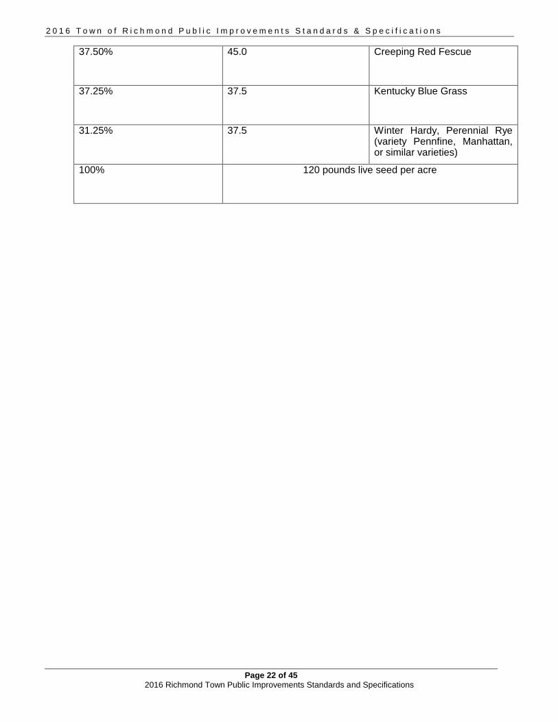
2 0 1 6 T o w n o f R i c h m o n d P u b l i c I m p r o v e m e n t s S t a n d a r d s & S p e c i f i c a t i o n s
Page 22 of 45 2016 Richmond Town Public Improvements Standards and Specifications
37.50% 45.0 Creeping Red Fescue
37.25% 37.5 Kentucky Blue Grass
31.25% 37.5 Winter Hardy, Perennial Rye (variety Pennfine, Manhattan, or similar varieties)
100% 120 pounds live seed per acre
2 0 1 6 T o w n o f R i c h m o n d P u b l i c I m p r o v e m e n t s S t a n d a r d s & S p e c i f i c a t i o n s
Page 23 of 45 2016 Richmond Town Public Improvements Standards and Specifications
3. STORM SEWER STANDARDS
This section pertains to design and construction requirements for both open and closed storm drainage systems in the Town and, in Section 3.5, presents design concepts for the reduction of stormwater runoff as well as methods for treating and handling that runoff. For additional detail, reference should be made to Volumes I and II of “The Vermont Stormwater Management Manual”, Volume1 and Volume 2, by the Vermont Agency of Natural Resources, dated August 2002 (or latest version). Refer to Figures 21 – 22.
3.1 DESCRIPTION This item shall consist of catch basins, manholes, and pipe used in closed storm drain systems or in open culvert applications, meeting the specifications for the diameter of pipe required and installed as indicated on the drawings. Except where approved by the Town, storm drainage systems for new developments shall be underground. Storm drainage calculations shall be provided as a part of the submittal of a site plan or preliminary subdivision plan. The Town may also require a detailed hydrological analysis for proposed developments. Developments that adversely impact existing storm drainage facilities will be expected to upgrade these facilities as a part of their development. All new culverts, catch basins, manholes, and pipes associated with storm drainage works shall be designed to accommodate at least a 25-year storm. The Town may require that detention basins be constructed down gradient of new developments to maintain storm runoff rates to adjoining properties that are at least equal to, but not greater than, pre-development rates for a 25-year design storm. In some instances, such as in deep, well drained sands or gravels, dry-well storm water disposal systems may be permitted; however, they must be capable of handling the 25-year runoff and are generally under the jurisdiction of the State Water Quality Division. The post-development stormwater volume calculated for the drainage area in which the improvements are proposed may also be required to meet the pre-development annual estimated volume when down-gradient stormwater systems and structures are shown to not be capable of handling the increased volume. In either case, the developer’s engineer shall submit all design calculations to the Town for review.
3.2 MATERIALS
Types of pipe: Types of pipe which may be used for storm drain lines are Reinforced Concrete Pipe (R.C.P.), High Density Polyethylene Pipe (HDPE), Polyvinyl Chloride Pipe (P.V.C.), or an approved equal. Types of pipe which may be used for culverts are Reinforced Concrete Pipe (R.C.P.), High Density Polyethylene Pipe (HDPE), or an approved equal. The Town will approve the types of pipe used. Reinforced concrete pipe: Pipe shall conform to the Vermont Standard Specifications for Construction, Section 710, and AASHTO, M170. Polyvinyl chloride pipe: Pipe shall conform to ASTM Specification D3034 or F679, (PVC) Sewer Pipe and Fittings, SDR35. High Density Polyethylene Pipe: Pipe shall conform to AASHTO Specifications M294 or MP6, and shall be equal to Advanced Drainage Systems, Inc. N-12 ProLink Ultra or N-12 HC pipe. Manholes: Where indicated on the plans, the contractor shall furnish and install manholes, which meet the requirements of the sanitary sewer manholes of these specifications. Catch basins: Catch basins shall be constructed of reinforced concrete and shall be provided with

2 0 1 6 T o w n o f R i c h m o n d P u b l i c I m p r o v e m e n t s S t a n d a r d s & S p e c i f i c a t i o n s
Page 24 of 45 2016 Richmond Town Public Improvements Standards and Specifications
cast iron frames and grates. Frames and grates shall be LeBaron LK12O, LKl2OA (for grades exceeding five percent), or an approved equal. Precast risers and base sections shall conform to the Vermont Standard Specifications for Construction, Section 604. Manhole and catch basin risers: Risers used to bring manhole and catch basin castings to final grade shall either be precast concrete rings and/or a product equal to “Infra-riser” multi-purpose rubber adjustment risers as manufactured by GNR Technology. Precast concrete rings shall be 4000 psi concrete and shall be specifically manufactured for this purpose.
3.3 SIZE The minimum size of pipe for closed storm drainage systems shall be 12” in diameter. For culverts crossing any public or private road ROW, no pipes smaller than 18” in diameter shall be used unless specifically approved by the Road Foreman. No driveway culverts shall be less than 18” in diameter unless physical constraints render this impossible or impractical, in which case, the Road Foreman may approve 15”.
3.4 CONSTRUCTION METHODS
Laying pipe: Storm drains and culverts shall be constructed in accordance with the Vermont Standard Specifications for Construction, Section 601, and on a trench bottom, prepared and bedded as shown on the drawings. Each pipe shall be checked just prior to laying to ensure that it is clear of all dirt and debris and shall be laid true to line and grade as indicated on the contract drawings. All joints shall be tight and inverts shall be continuous.
Concrete pipe joints shall be the rubber gasket type, HDPE pipe joints shall be gasketed bell and spigot and PVC pipe shall be joined with standard push-on type joints using elastomeric gaskets.
Storm drains and culverts with water flow velocities greater than 12 feet per second shall require special design, which must be approved by the Town.
Backfilling: All material for backfilling shall be free of roots, stumps, and frost. Bedding and backfill for all pipe lines shall be placed in 6" layers, each layer being thoroughly compacted to not less than 95 percent of maximum dry density as determined by the AASHTO-T-99, Method A, Standard Proctor by a means approved by the Town. PVC pipe shall have a minimum of 3' of cover.
Pipe bedding: Reinforced concrete pipe shall be bedded from the trench bottom to the centerline of the pipe, and then backfilled to a height of 1' above the top of the pipe with material excavated from the trench having no stones larger than 3" in the longest dimension. Should no excavated material be suitable, sand or gravel shall be used.
HDPE and PVC pipe shall be bedded from the trench bottom to a height of 6” above the top of pipe with sand or gravel.
Headwalls: The Contractor shall construct concrete or rubble masonry headwalls or shall install pipe-specific manufactured end sections at the outlet end of all closed storm drain systems and at both ends of all culverts, unless specifically waived by the Town. Concrete headwalls shall meet the requirements as shown on VTrans Standards D-33 and D-34.
If constructed of concrete or masonry rubble, headwalls shall conform to the Vermont Standard Specifications for Construction, Section 602.
All concrete utilized for this purpose shall meet the requirements of Class B Concrete as per the Vermont Standard Specifications for Construction, Section 501.
Casting adjustment to grade: Castings shall be brought to final grade through the use of one or both precast concrete rings and/or rubber adjustment risers. When both are used, the concrete ring shall be set first, followed by one or more rubber risers. Tapered rubber risers shall be used to match the grade across the casting with the grade of the surrounding road surface. Rubber risers shall be bonded and sealed to adjacent surfaces with the sealant/adhesive recommended by the manufacturer.

2 0 1 6 T o w n o f R i c h m o n d P u b l i c I m p r o v e m e n t s S t a n d a r d s & S p e c i f i c a t i o n s
Page 25 of 45 2016 Richmond Town Public Improvements Standards and Specifications
3.5 TREATED GUTTERS
Treated gutters (ditches) shall be constructed in accordance with Vtrans Standard D-3. 3.6 STORMWATER MANAGEMENT AND BEST MANAGEMENT PRACTICES
Simply stated, stormwater management (SWM) addresses the quantity of stormwater runoff, while best management practices (BMP) address the quality of the runoff. Both share an important role in the total stormwater picture and often, they are intertwined. Some of the BMPs that can be utilized to control impacts of stormwater runoff from new projects or from existing densely developed areas are as follows:
Minimize the release of pollutants into the discharge area Implement and maintain proper sediment control throughout construction Maintain catch basins Minimize use of road salt Eliminate combined sewer overflows
Use the pretreatment of soils and vegetation to treat runoff before it is discharged to receiving waters
Use vegetated buffer strips adjacent to all water courses Use vegetated swales adjacent to roads and parking areas Utilize ponds, detention basins, sedimentation basins, infiltration facilities, filters,
and natural or artificial wetlands to treat/dispose of the runoff Use plunge pools and/or stone splash pads to dissipate energy at pipe outlets
Modify structural drainage system design to minimize impacts
Use curbless roads and roadside swales Use discontinuous pavements with grass shoulders and vegetated islands (e.g., in
parking lots) Direct rooftop runoff away from structured drainage systems and onto grass areas Use sediment basins and oil/grit separators to reduce pollutants Use porous or pervious materials for driveways and parking areas, and when used
to mitigate stormwater to attain permit compliance, infiltration maintenance issues are adequately addressed in a permit condition.
Employ headwalls and/or wingwalls to minimize erosion and the potential for undermining where appropriate
The Agency of Natural Resources professes an “integrated stormwater management “ approach which combines good site design practices with the design of stormwater infrastructure to reach quantity and quality goals. The steps in this process follow:
Site designs which use natural features to reduce runoff and pollutants Control runoff volumes to attain management goals in terms of water quality, channel
protection, overbank flood protection, and extreme flood protection Assess downstream property impacts Apply any available design credits to runoff volume control attained from the principles of
good site design Choose and design the most appropriate structural control measures for the given site and
watershed
2 0 1 6 T o w n o f R i c h m o n d P u b l i c I m p r o v e m e n t s S t a n d a r d s & S p e c i f i c a t i o n s
Page 26 of 45 2016 Richmond Town Public Improvements Standards and Specifications
The Agency further provides several stormwater management goals which can be viewed as benchmarks for the design and review of projects.
Minimize runoff and maximize use of pervious areas for stormwater treatment SWM should utilize structural and non-structural elements. Where possible, non-structural
features should be implemented to reduce reliance on structural elements New development runoff must receive adequate treatment before discharge to waters of
the State or to jurisdictional wetlands Infiltration into the ground should be encouraged Structural stormwater treatment practices for new projects must be designed to remove
80% of suspended solids and 40% of the total phosphorus load in the runoff The post-development 25-year peak discharge rate must not exceed the pre-development
rate Stream channels must be protected from erosion by providing extended detention storage
of 12 to 24 hours for the 1 year storm or by other approved means All structural stormwater treatment elements must have an enforceable O&M agreement to
ensure continued proper function Redevelopment and infill projects should maximize treatment and control of runoff from
existing impervious surfaces Certain intensive land uses may be deemed “stormwater hotspots” because of a high
potential for pollutant loading and, as such, may require specific control and treatment practices
To the extent possible, stormwater discharges should be returned to the same drainage watershed from which they originated
It is beyond the scope of this document to detail all the various design concepts which can be utilized to reach these goals, but the several preceding paragraphs do set the tone for a comprehensive stormwater management philosophy and that the reader will further refer to the State manuals to seek specific details and procedures for design. With respect to the management and maintenance of Town roads, the Town road maintenance crew will collectively attend a minimum of 6 hours of training per year on best management practices and will keep documentation of such training for a minimum of 3 years. Resources The following resources are recommended to assist Town officials and designers in evaluating proposals. These Standards shall apply in all cases, however, if conflicting recommendations or specifications become evident during design, with any other resource, permit or document, those conflicts may be resolved through the variance procedures in Section 1.8 and 1.9 of these Standards. For information on stormwater permits and rules in Vermont, check with the Vermont Watershed Management Division Stormwater Program. For information on stormwater Best Management Practices (BMP), check out the International Stormwater BMP Database. For general stormwater design, planning resources and guidance, visit the Stormwater Manager’s Resource Center.
2 0 1 6 T o w n o f R i c h m o n d P u b l i c I m p r o v e m e n t s S t a n d a r d s & S p e c i f i c a t i o n s
Page 27 of 45 2016 Richmond Town Public Improvements Standards and Specifications
4. WATER DISTRIBUTION STANDARDS Water mains, hydrants, house connections and other water distribution improvements in the Town of Richmond shall be built in accordance with this section of the standards. Refer to Figures 12 – 14. For all new and replacement connections to the municipal system approvals and inspections are coordinated with the Town Water and Sewer Commission and the Water Resource Department.
4.1 DESCRIPTION This item shall consist of the excavation and backfilling required for the complete construction of the water mains and services which shall include valves, tees, hydrants, elbows, reducers, and all other appurtenances necessary for a complete water main system as indicated in the accepted drawings. All material and installations shall be completed by the Contractor and approved by the Town.
4.2 GENERAL WATERLINE MATERIALS
A. Polyvinyl Chloride Water Pipe:
Pipe shall be Polyvinyl Chloride (PVC) with a minimum diameter or 8” and shall conform to current AWWA Specification C900 (C905 for large sizes). The minimum thickness class shall be DR-14 (305 psi) and joints shall be the push-on, except at fittings where they shall be mechanical.
B. Fittings:
Ductile iron fittings shall conform to AWWA C11O and ANSI Specification A21.10, 350 pounds working pressure, and be of a compact body design. Ductile iron fittings larger than 12" shall have a standard body length equal to Class 250 cast iron fittings. Cast Iron Class 250 fittings will be allowed in lieu of ductile iron fittings in sizes larger than 12".
C. Resilient Seat Gate Valves:
Valves shall be manufactured to meet all requirements of AWWA Specifications C509. Valves 12" and smaller shall be bubble-tight, zero leakage at 200 psi working pressure. Valves shall have non-rising stems, open counter-clockwise, and be provided with a 2" square-operating nut with arrow cast in metal to indicate direction of opening. Each valve shall have maker's name, pressure rating, and year in which manufactured, cast on the body. Prior to shipment from the factory, each valve shall be tested by hydrostatic pressure equal to twice the specified working pressure. Buried valves shall be installed with a valve box.
D. Valve Boxes:
Cast iron three-piece slide-type; 5 1/4" shaft; 6' trench depth. Cast iron cover; shall be marked "WATER" and shall indicate the direction of opening.
E. Fire Hydrants:
Fire hydrants shall be American Flow Control Waterous Pacer and shall conform to AWWA C502 with the following specifications:

2 0 1 6 T o w n o f R i c h m o n d P u b l i c I m p r o v e m e n t s S t a n d a r d s & S p e c i f i c a t i o n s
Page 28 of 45 2016 Richmond Town Public Improvements Standards and Specifications
Main Valve Opening: 5 1/4 inches Nozzle Arrangement: Two 2 ½-inch hose nozzles with National Standard thread
One 4 ½-inch pumper nozzle with National Standard thread Inlet Connection: 6-inch mechanical joint Operating Nut: Standard 1 ½-inch pentagon Direction of Opening: Counterclockwise Color: Enameled yellow Depth of Bury: Hydrant shall be installed to the manufacturer's instructions with
nozzles about 18 inches above finish grade. F. Hydrant Branches:
Hydrant assemblies shall consist of a 6" mechanical joint valve, the appropriate length of 6" ductile iron cement-lined Class 52 pipe or 6” PVC pipe, and the fire hydrant. The hydrant shall have at least 15 inches between the bottom of the steamer cap and the ground. For single-family house subdivisions, there will be at least one hydrant at each intersection and a maximum of 450 feet between hydrants with a minimum water flow of 500 gallons per minute with a 20 p.s.i. residual pressure from each hydrant. There shall be a 10' x 10' easement around each hydrant, when not located within the public right-of-way. Hydrant drain plugs shall be removed unless otherwise directed by the Town.
4.3 TAPPING SLEEVES
Tapping sleeves shall be a split design with two stainless steel halves bolted together. Shells and lugs shall be 304 stainless steel, gaskets shall be virgin SBR compounded for potable water service and the flange shall be ductile iron meeting ASTM 536-80, Grade 65-45-12 welded to the neck. Minimum testing pressure shall be 200 psi. Sleeves shall be equal to “SST” Stainless Steel Tapping Sleeve supplied by E. J. Prescott, Inc.
4.4 WATER SERVICE CONNECTION A. General requirements:
The Contractor shall install 3/4'' - 2" copper services as indicated on the Contract Drawings or as directed by the Town. Each service shall consist of a corporation, curbstop, copper tubing, and a curb box with service rod. Corporation shall be attached to the ductile iron pipe by means of a direct tap and to PVC pipe through the use of an approved saddle.
B. Corporations:
Corporations shall be Waterworks Brass and manufactured in accordance with applicable AWWA standards. Corporations shall have Mueller threads, adopted as AWWA Figure 1, at the inlet and a compression-type fitting at the outlet. Both inlet and outlet shall be of the same size. Corporations shall be directly tapped into ductile iron pipe larger than 2" in diameter. In no other instance, except when a tapping sleeve and valve is used, shall a tap be made without a corporation. Corporations shall be Mueller H15009 or equal. Corporations shall be installed on PVC pipe with the use of an approved Stainless Steel band saddle.
C. Curbstops:
Curbstops shall be a quarter-turn, plug-type valve with an "O" ring-type seal and

2 0 1 6 T o w n o f R i c h m o n d P u b l i c I m p r o v e m e n t s S t a n d a r d s & S p e c i f i c a t i o n s
Page 29 of 45 2016 Richmond Town Public Improvements Standards and Specifications
manufactured of Waterworks Brass in accordance with applicable AWWA standards. The curbstop shall open left and have a positive stop. No curbstop shall have the ability to drain the service line. Both inlet and outlet of the curbstop shall have compression-type fittings. The tee head of the curbstop shall have provision for the connection of a service rod. Curbstops shall be Mueller H-1504-2 or equal.
D. Copper water service tubing:
Copper tubing shall be Type “K”, soft temper, conforming to ASTM B88. The name or trademark of the manufacturer and type shall be stamped at regular intervals along the pipe.
E. Curb Boxes and Rods:
Curb boxes shall be of the sliding adjustable-type capable of adjusting from 5' - 6'. The base of the box shall be arch-type so as to prevent the box from resting directly on the curbstop. The adjustable upper section shall be one inch (1" in diameter for use with 3/4" and 1" curbstops.
For larger curbstops, the upper section shall be 1¼" in diameter. Stationary rods affixed to the key of the curbstop shall be thirty inches (30" in length for 3/4" and 1" curbstops and 24" for larger curbstops.
The cover of the box shall have a countersunk brass pentagon plug.. The word "WATER" shall be inscribed on the cover of the box. Both the cover and the upper section of the box shall be able to be located with an aqua-type metal locator.
F. House Services Construction Methods:
House Services: The Contractor shall make all necessary taps into the water main and, for each lot, will install an approved brass corporation stop. The Contractor shall also connect ¾ " type "K" copper service pipe to the corporation, which shall be connected to a ¾" type brass curbstop with inlet and outlet for ¾" type "K" copper service pipe. Such curbstop shall be located not less than 5'-6" below the ground surface and shall be accessible from the surface through an approved valve box. All connections shall be compression type.
House Connections: The house connections shall be made by installing ¾" type "K" copper pipe on the end of the approved brass curbstop and proceeding through the cellar wall to an approved ¾" ball valve. This ball valve, along with a ¾" meter, meter couplings and a 3/4” residential dual check valve shall be purchased through the Water Resources Department and shall be installed by the contractor in accordance with good plumbing practices.
4.5 GENERAL CONSTRUCTION METHODS
A. Inspection and Testing:
All pipe and fittings shall be inspected and tested in accordance with the manufacturer's specifications and the aforementioned AWWA Specifications. The Contractor shall furnish for approval certification from the pipe manufacturer that all tests have been performed with satisfactory results. Pipe shall not be installed without the Town’s approval.
B. Installation:

2 0 1 6 T o w n o f R i c h m o n d P u b l i c I m p r o v e m e n t s S t a n d a r d s & S p e c i f i c a t i o n s
Page 30 of 45 2016 Richmond Town Public Improvements Standards and Specifications
Pipe, fittings, and accessories shall be carefully handled to avoid damage. Prior to the date of acceptance of the project, the contractor shall replace any new pipe or accessory found to be defective at any time, including after installation, at his own expense. All installation and testing shall be done in accordance with AWWA Standard C600 and ANSI Specification A21.11. All pipe showing cracks shall be rejected. If cracks occur in the pipe, the contractor may, at his own expense and with the approval of the Town, cut off the cracked portions at a point at least 12 inches from the visible limits of the crack and use the sound portion of the pipe.
All pipe and fittings shall be cleared of all foreign matter and debris prior to installation and shall be kept clean until the time of acceptance. At all times, when the pipe laying is not actually in progress, the open ends of the pipe shall be closed by temporary watertight plugs or by other approved means. If water is in the trench when work is resumed, the plug shall not be removed until all danger of water entering the pipe has passed. The pipe shall be installed in trenches and at the line and grade shown on the Contract Drawings. Any deflection joints shall be within the limits specified by the manufacturer. All piping and appurtenances connected to the equipment shall be supported so that no strain will be imposed on the equipment. If the equipment manufacturer's specifications include that piping loads are not to be transferred, the contractor shall submit certification of compliance. Concrete thrust blocks shall be installed on all plugs, tees, and bends deflecting 11¼ degrees or more. Care shall be taken to ensure that concrete will not come in contact with flanges, joints, or bolts. The required area of thrust blocks are indicated on the plans or shall be as approved by the Town. In lieu of thrust blocks, ductile iron retainer glands for mechanical joint pipe may be used.
Whenever sewers cross under watermains, the watermain shall be laid at such an elevation that the bottom of the watermain is at least 18 inches above the top of the sewer. This vertical separation shall be maintained for that portion of the watermain located within 10 feet horizontally of any sewer it crosses.
When it is impossible to obtain horizontal and vertical separation, both the watermain and sewer shall be constructed with watertight joints and shall be pressure tested to assure water tightness before backfilling. No watermain shall pass through, or come in contact with, any part of a sewer manhole. There shall be no physical connection between the distribution system and any pipes, pumps, hydrants, or tanks, which are supplied or may be supplied with a water supply that is, or may be, contaminated. In instances where the use of different types of pipe requires joining, the contractor shall furnish and install all necessary adapters. All trenching safety standards shall be in conformance with all applicable State and Federal guidelines and as specified on the plans. The contractor shall, at all times, keep the trenches entirely free of water until all work is finished and ready for backfilling.
2 0 1 6 T o w n o f R i c h m o n d P u b l i c I m p r o v e m e n t s S t a n d a r d s & S p e c i f i c a t i o n s
Page 31 of 45 2016 Richmond Town Public Improvements Standards and Specifications
For PVC, thoroughly compacted bedding of sand shall be provided from 6” below the pipe to 6” above the pipe. Any unstable trench bottom shall be stabilized to the satisfaction of the Town using crushed stone, before proceeding with placement of bedding. In cases of significant presence of ground water, the Town may require all or some of the bedding to be crushed stone. After the various pipelines have been installed, the trenches and other areas to be filled shall be backfilled to subgrade with, wherever possible, material excavated from the trench. No backfilling will be allowed until any concrete masonry has set sufficiently, as determined by the Town. All material for backfilling shall be free of roots, stumps, and frost. Materials used for backfilling trenches shall be free of stones weighing over 30 pounds. No stones measuring over 3" in the longest dimension shall be placed within 1' of the pipeline being backfilled. Backfill for all pipelines shall be placed in 6" layers, each layer being thoroughly compacted to not less than that of 95 percent maximum dry density as determined by the AASHTO-T-99 Standard Proctor. Particular precautions shall be taken in the placement and compaction of the backfill material in order not to damage the pipe or structure. The backfill shall be brought up evenly. Surplus excavated materials not used for backfill shall be disposed of in a manner satisfactory to the Town. A town zoning permit may be required for fill or disposal locations. All surplus material or spoil shall be removed promptly and disposed of so as not to be objectionable to abutters or to the general public.
Valve boxes are to be installed on all buried valves. The boxes shall be cast iron, with a minimum 5 ¼" in diameter and long enough to extend from the valve to finished grade. The boxes shall enclose the operating nut and the stuffing box of the valve. Valve boxes shall not transfer loads into the valve. Covers shall be close-fitting and dirt-tight with the top of the cover flush with the top of the box rim. Covers shall be marked "Water" with an arrow indicating the direction of opening. Valve boxes shall be three-piece screw-type manufactured by Kennedy, Figure 121, or equal.
C. Disinfection:
Chlorination of the water main shall be conducted by the Contractor only after the main has been flushed and a clear stream is obtained as determined by the Town. The contractor shall furnish all labor, equipment, materials, and tools necessary to disinfect the pipe and appurtenances in accordance with AWWA Standard for Disinfecting Watermains, C651. The method of disinfection shall be by the continuous feed method unless otherwise approved by the Engineer. After filling, flushing, and the addition of chlorine solution, chlorine concentration within the pipe shall be at least 25 mg/l for 24 hours. All disinfection shall be performed under the supervision of the Engineer. The disinfection process shall be deemed acceptable only after samples of water from the flushed disinfected main show no evidence of bacteriological contamination. The pipeline and appurtenances shall be maintained in an uncontaminated condition until final acceptance. Disinfection shall be repeated when and where required.

2 0 1 6 T o w n o f R i c h m o n d P u b l i c I m p r o v e m e n t s S t a n d a r d s & S p e c i f i c a t i o n s
Page 32 of 45 2016 Richmond Town Public Improvements Standards and Specifications
D. Field Testing:
Except as otherwise directed, all pipelines shall be tested by the Contractor. Pipelines laid in excavation or bedded in concrete shall be tested prior to backfilling or the placing of concrete, and any exposed piping shall be tested prior to field painting.
The Contractor shall furnish all gauges, testing plugs, caps, and all other necessary equipment and labor to perform leakage and pressure tests in sections of an approved length. All water required for testing shall be potable. All testing shall be conducted in the presence of the Engineer. For the pressure test, the Contractor shall develop and maintain for two hours 125 percent of the working pressure measured in pounds per square inch. Failure to hold the designated pressure for the two-hour period constitutes a failure of the section tested. The leakage pressure shall be performed concurrently with the pressure test. During the test, the Contractor shall measure the quantity of water required to maintain the test pressure. Leakage shall not exceed the quantity given by:
L = ND (square root of P) / 7,400 where: L = leakage in gallons/hour
N = number of joints in the tested line D = diameter of pipe in inches P = average test pressure in psi
All testing shall be conducted in accordance with AWWA C600 latest revision. Should any section of pipe fail either the pressure or leakage tests, the contractor shall do everything necessary to locate and repair and replace the defective pipe, fittings, or joints at no expense to the Owner. If, for any reason, the Town should alter the foregoing procedures, the Contractor shall remain responsible for the tightness of the line with the above requirements.
E. Frost Protection of Shallow Waterlines:
Waterlines with less than 6'-0" of cover over the crown, or where indicated on the plans, shall be protected against freezing by installation of 3" thick extruded polystyrene insulating sheets equal to Styrofoam SM with a width of 3' or twice the pipe diameter, whichever is greater. In areas of the municipality without curbing, or where there is the need for roadway ditching or drainage structures near or over waterlines, insulating sheets may be required within the area that might be impacted by said activities or other activities, i.e. there is a possibility that existing or future drainage improvements or maintenance activities or improvements may reduce the required 5’ – 6” of cover over the crown.
The sheets shall be placed 6" above the crown of the main after compaction of the 6" lift immediately above the crown. Care shall be exercised by the Contractor during backfill and compaction over the Styrofoam sheets to prevent damage to the sheets. Styrofoam sheets shall meet the compressive strength requirements of ASTM D1621-73 and shall be as manufactured by Dow Chemical Company, Midland, Michigan, or equivalent.

2 0 1 6 T o w n o f R i c h m o n d P u b l i c I m p r o v e m e n t s S t a n d a r d s & S p e c i f i c a t i o n s
Page 33 of 45 2016 Richmond Town Public Improvements Standards and Specifications
5.0 SANITARY SEWER STANDARDS
Sanitary sewers and their appurtenances shall be designed and constructed according to this section of the standards. Refer to Figures 15 – 20. For all new and replacement connections to the municipal system, approvals and inspections are coordinated with the Town Water and Sewer Commission and the Water Resource Department.
5.1 DESCRIPTION This item shall consist of the excavation and backfilling required for the complete construction of gravity sanitary sewers, force mains, and all appurtenant construction related thereto, including chimneys, service connections, thrust blocks, and other items necessary for a complete sanitary sewer system as indicated on the drawings. Sewer mains from more than one dwelling unit shall be a minimum pipe diameter of 8". All testing required under this section shall be done by the Contractor and shall be observed by the Town.
5.2 MATERIALS A. Types of Pipe:
Types of pipe which shall be used for the various parts of work are as follows: 1. Gravity sewers shall be PVC solid wall pipe meeting ASTM Specifications D3034
2. Force mains shall be PVC SDR21 or restrained joint pressure pipe.
B. PVC Pipe for Gravity Sewers PVC sewer pipe shall conform in all respects to the latest revision of ASTM Specifications D-3034 or F679, Type PSM, Polyvinyl Chloride (PVC) Sewer Pipe and Fittings, SDR35. Wall thickness of all PVC pipe shall meet ASTM Specifications for SDR35 pipe. All pipe and fittings shall be clearly marked as follows:
Manufacturer's Name and Trademark Nominal Pipe Size Material Designation 12454C PVC or 12364C PVC Legend "Type PSM SDR35 PVC Sewer Pipe" or
"PS 46 PVC Sewer Pipe" Designation ASTM D-3034 or F679
Joints shall be push-on type using elastomeric gaskets and shall conform to ASTM F-477 and D-3212. The gaskets shall be factory installed. The pipe shall be furnished in nominal 13-foot lengths. Sufficient numbers of short lengths and full machine fittings shall be provided for use at manholes, chimneys, and connections. All connections will require the use of manufactured fittings. Field fabricated, saddle-type connections will not be considered acceptable. Any pipe or fitting having a crack or other defect or which has received a severe blow shall be marked rejected and removed at once from the work site. All field cuts are to be made with saw and 90 degree miter box. Bevel the cut end to the same as the factory bevel and remove all interior burrs. Measure and place a homing mark on the pipe before assembling. The pipe installed under this specification shall be installed so that the initial deflection, measured as described below, shall be less than 5%.

2 0 1 6 T o w n o f R i c h m o n d P u b l i c I m p r o v e m e n t s S t a n d a r d s & S p e c i f i c a t i o n s
Page 34 of 45 2016 Richmond Town Public Improvements Standards and Specifications
Deflection tests shall be performed on all flexible pipe after the final backfill has been in place for at least 30 days. The deflection test shall be run using a rigid ball or mandrel having a diameter equal to 95 percent of the inside diameter of the pipe. No mechanical pulling devices shall be used during the deflection tests. All pipe not meeting the deflection test shall be re-excavated and replaced at the Contractor's expense. The manhole water stop gasket and stainless steel clamp assembly must be approved by the Town prior to the installation of any pipe.
The Contractor will submit certification that the materials of construction have been sampled, tested, inspected, and meet all the requirements including wall thickness in accordance with ASTM D3034 or ASTM F679 for all pipe and fittings to be included in the project work.
PVC pipe shall not be installed when the temperature drops below 32 degrees Fahrenheit or goes above 100 degrees Fahrenheit. During cold weather, the flexibility and impact resistance of PVC pipe is reduced. Extra care is required when handling PVC pipe during cold weather. PVC pipe shall not be stored outside and exposed to prolonged periods of sunlight, as pipe discoloration and reduction in pipe impact strength will occur. Canvas or other opaque material shall be used to cover PVC pipe stored onsite.
C. Polyvinyl Chloride Pipe for Force Mains: 1. SDR 21 PVC pipe conforming to ASTM D2241, with resin conforming to ASTM D1784 and gaskets to ASTM D1869 and F477. This pipe shall be used in buried applications. 2. Restrained joint PVC pressure pipe equal to Certa-Lok VIP Restrained Joint Municipal Water Pipe. Couplings shall be either permanent or non-permanent use Certa-Lok joints, as dictated by the Town. PVC pipe shall meet the requirements of AWWA C900 in pressure class 150. This product shall be used in insulated above ground applications.
D. Manholes:
The Contractor shall construct reinforced concrete manholes and drop manholes to the dimensions at the locations shown on the contract drawings. All precast reinforced concrete manhole sections shall conform to the latest version of the ASTM Specification C478. The footing may be either cast-in-place with Class B concrete or precast and shall conform to the dimensions indicated on the plans.
Shelves shall be constructed with Class B concrete as defined in Section 501 of the Vermont Standard Specifications for Construction. Inverts for sewer manholes shall be as shown on the plans and details and shall be constructed with Class B concrete or, for straight runs, segments of pipe cut in half longitudinally. Inverts shall have the exact shape of the sewer to which they are connected, and any change in size or direction shall be gradual and even. All construction of sewer manholes must be carried out to ensure watertight work. Any leaks in manholes shall be caulked and completely repaired to the satisfaction of the Engineer or the entire structure shall be removed and rebuilt. The entire exterior surface of the manholes shall be coated with a watertight sealant.
All manholes are to be provided with copolymer polypropylene plastic rungs with steel reinforcement 8" on center. All manholes shall be provided with tough, gray, cast iron manhole frames and covers which shall be through holed and vented. All iron castings shall be thoroughly cleaned and then coated with hot tar before being delivered. Frames and covers shall be LeBaron LC 266 Type C, or an approved equal, and have a minimum weight of 400 pounds.

2 0 1 6 T o w n o f R i c h m o n d P u b l i c I m p r o v e m e n t s S t a n d a r d s & S p e c i f i c a t i o n s
Page 35 of 45 2016 Richmond Town Public Improvements Standards and Specifications
Precast risers and bases for manholes shall conform to ASTM Specification C-478. The pipe opening in the precast manhole riser shall have a cast-in-place flexible gasket or an equivalent system for pipe installation as approved by the Engineer. Joints between manhole risers shall be rubber "O" ring seals or soft Butyl joint sealer (rope form).
Manholes shall be placed at all changes in slope, size, alignment of pipe, at the ends of each line, and at intervals no greater than 300'.
E. Risers for manholes:
Risers used to bring manhole castings to final grade shall either be precast concrete rings and/or 2 to 6 layers of a product equal to Ladtech, Inc. injection molded high density polyethylene adjustment rings. Precast concrete rings shall be 4000 psi concrete and shall be specifically manufactured for this purpose.
5.3 CONSTRUCTION METHODS A. Excavations:
Excavations shall be made to a point at least 6" below the pipe invert to accommodate the bedding material. All excavations, are to be kept dry while pipe is being laid and until each joint and pipe has been inspected by the Town and approval given to commence backfilling operations.
B. Laying Sewer Pipe:
The bell end of the pipe shall face upgrade at all times and be placed in such a position as to make the invert even when the succeeding section is inserted. Where required by adverse grading conditions, the Contractor shall fill any gully to make a suitable bedding for the sewer pipe. The fill shall be mechanically compacted to a 95 percent dry density by the AASHTO-T-99, Method A (Standard Proctor) test, upon which the 6" of bedding material shall be placed.
Any pipe which is not laid to grade and alignment shall be re-laid to the satisfaction of the Town. The bedding material shall be placed and compacted on each side of the pipe to a height equal to one-half the pipe diameter and for the full width of the excavated trench and as shown on the accepted plans. Bedding materials shall be as follows: PVC gravity pipe – ¾” – 1 ½” crushed stone PVC force main – sand or gravel
C. Backfill:
Backfill shall consist of approved material placed in 6" layers with each layer being thoroughly compacted to not less than 95 percent of maximum dry density as determined by the AASHTO-T-99 Standard Proctor by means approved by the Town. No stones in excess of 3" in diameter shall be placed within 1' of the outside of the pipe. Particular precautions shall be taken in placement and compaction of the backfill material in order not to damage and/or break the pipe. The backfill shall be brought up evenly on both sides of the pipe for its full length. Walking or working on the completed pipeline, except as may be necessary in tamping or backfilling, shall not be permitted until the trench has been backfilled to a height of at least

2 0 1 6 T o w n o f R i c h m o n d P u b l i c I m p r o v e m e n t s S t a n d a r d s & S p e c i f i c a t i o n s
Page 36 of 45 2016 Richmond Town Public Improvements Standards and Specifications
2' on the top of the pipes. During construction, all openings to the pipelines shall be protected from the entering of earth or other materials.
D. Concrete Cradle and Encasement for Pipe:
Where required on the plans or as directed by the Town, a concrete cradle shall be used to bolster and strengthen pipe. Where required on the plans or as directed by the Town, concrete encasement of the sewer line will be made to protect nearby wells or waterlines for stream crossings or for similar purposes. All concrete will be Class B as defined in the State of Vermont Standard Specifications for Construction, Section 501, and will meet the requirements of that section.
E. Frost Protection for Shallow Sewers:
Sewers with less than 5.5') of cover over the crown or where indicated on the plans shall be protected against freezing by installation of 3"thick extruded polystyrene insulating sheets equal to Styrofoam SM with a width of 3' or twice the pipe diameter, whichever is greater. The sheets shall be placed six inches (6" above the crown of the sewer after compaction of the six-inch lift immediately above the crown. Care shall be exercised by the Contractor during backfill and compaction over the Styrofoam. Sheets shall meet the compressive strength requirements of ASTM D1621-73 and shall be equal to those manufactured by Dow Chemical Company, Midland, Michigan.
F. Leakage Tests and Allowances for Gravity Sewers:
The low-pressure air test will be used to simulate infiltration or exfiltration rates into or out of all gravity sewers. The Contractor will furnish all facilities and personnel for conducting the test. Final acceptance of the sewer shall depend upon the satisfactory performance of the sewer under test conditions. The test shall be performed on pipe between adjacent manholes after backfilling has been completed and compacted. All wyes, tees, laterals, or end-of-side sewer stubs shall be plugged with flexible-joint caps, or an acceptable alternate, securely fastened to withstand the internal test pressure. Such plugs or caps shall be readily removable, and their removal shall provide a socket suitable for making a flexible-jointed lateral connection or extension. Prior to testing for acceptance, the pipe should be cleaned by passing through the pipe a full-gauge squeegee. It shall be the responsibility of the Contractor to have the pipe cleaned. Immediately following the pipe cleaning, the pipe installation shall be tested with low-pressure air. Air shall be slowly supplied to the plugged air installation until the internal air pressure reaches 4.0 pounds per square inch greater than the average back pressure of any ground water that may submerge the pipe. At least two minutes shall be allowed for temperature stabilization before proceeding further. The pipe line shall be considered acceptable when tested at an average pressure of 3.0 pounds per square inch greater than the average back pressure of any ground water that may submerge the pipe if:
1. the total rate of air loss from any section tested in its entirety between manhole and cleanout structures does not exceed 2.0 cubic feet per minute; or
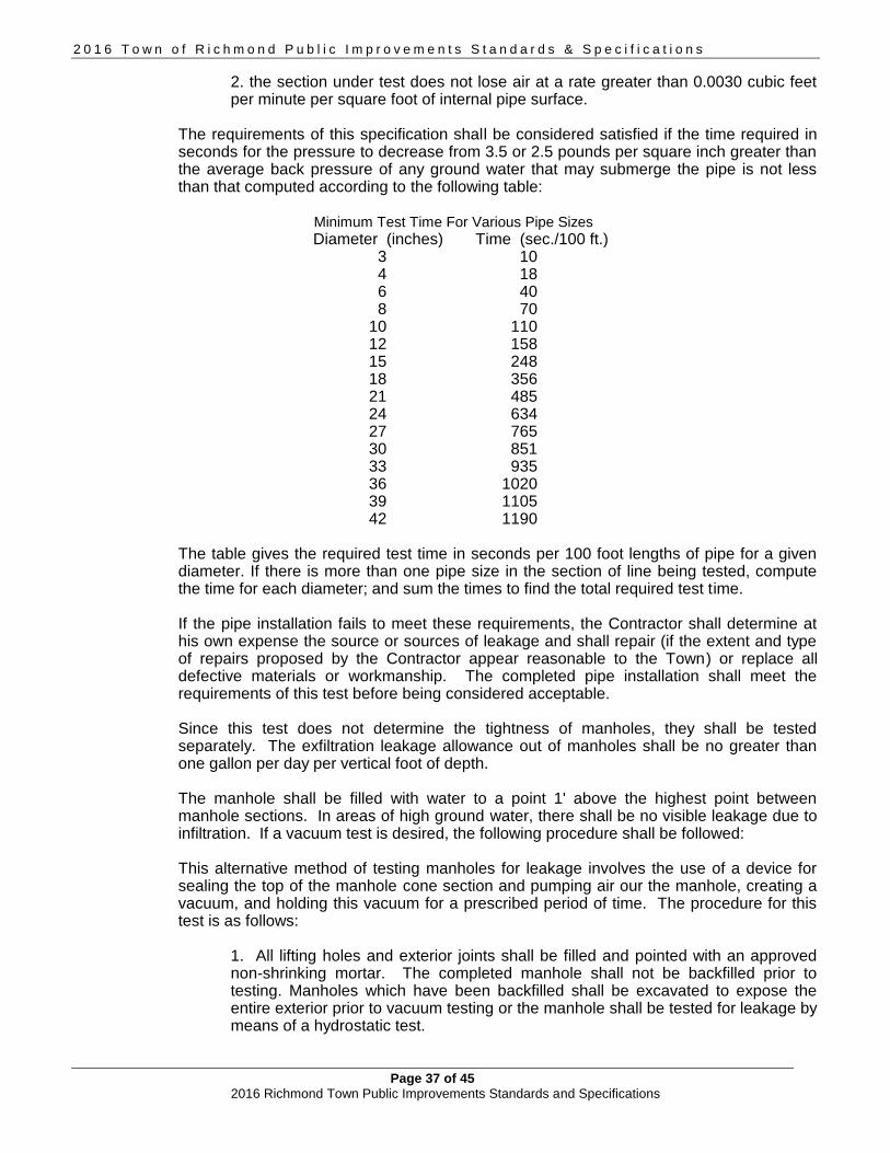
2 0 1 6 T o w n o f R i c h m o n d P u b l i c I m p r o v e m e n t s S t a n d a r d s & S p e c i f i c a t i o n s
Page 37 of 45 2016 Richmond Town Public Improvements Standards and Specifications
2. the section under test does not lose air at a rate greater than 0.0030 cubic feet per minute per square foot of internal pipe surface.
The requirements of this specification shall be considered satisfied if the time required in seconds for the pressure to decrease from 3.5 or 2.5 pounds per square inch greater than the average back pressure of any ground water that may submerge the pipe is not less than that computed according to the following table:
Minimum Test Time For Various Pipe Sizes
Diameter (inches) Time (sec./100 ft.) 3 10 4 18 6 40 8 70
10 110 12 158 15 248 18 356 21 485 24 634 27 765 30 851 33 935 36 1020 39 1105 42 1190
The table gives the required test time in seconds per 100 foot lengths of pipe for a given diameter. If there is more than one pipe size in the section of line being tested, compute the time for each diameter; and sum the times to find the total required test time. If the pipe installation fails to meet these requirements, the Contractor shall determine at his own expense the source or sources of leakage and shall repair (if the extent and type of repairs proposed by the Contractor appear reasonable to the Town) or replace all defective materials or workmanship. The completed pipe installation shall meet the requirements of this test before being considered acceptable. Since this test does not determine the tightness of manholes, they shall be tested separately. The exfiltration leakage allowance out of manholes shall be no greater than one gallon per day per vertical foot of depth.
The manhole shall be filled with water to a point 1' above the highest point between manhole sections. In areas of high ground water, there shall be no visible leakage due to infiltration. If a vacuum test is desired, the following procedure shall be followed: This alternative method of testing manholes for leakage involves the use of a device for sealing the top of the manhole cone section and pumping air our the manhole, creating a vacuum, and holding this vacuum for a prescribed period of time. The procedure for this test is as follows:
1. All lifting holes and exterior joints shall be filled and pointed with an approved non-shrinking mortar. The completed manhole shall not be backfilled prior to testing. Manholes which have been backfilled shall be excavated to expose the entire exterior prior to vacuum testing or the manhole shall be tested for leakage by means of a hydrostatic test.

2 0 1 6 T o w n o f R i c h m o n d P u b l i c I m p r o v e m e n t s S t a n d a r d s & S p e c i f i c a t i o n s
Page 38 of 45 2016 Richmond Town Public Improvements Standards and Specifications
2. All pipes and other openings into the manhole shall be suitably plugged in a manner to prevent displacement. 3. A plate with an inflatable rubber ring the size of the top of the manhole shall be installed by inflating the ring with air to a pressure adequate to prevent leakage of air between the rubber ring and manhole wall. 4. Air shall then be pumped out of the manhole through an opening in the plate until a vacuum is created inside of the manhole equal to 10" of mercury on an approved vacuum gauge. The removal of air shall then be stopped and the test time begun. 5. The vacuum must not drop to below 9" of mercury with a two-minute test period. If more than 1" drop in vacuum occurs within the two-minute test period, the manhole has failed the test and shall be repaired or reconstructed and retested. 6. Following satisfactory test results, the manhole may be backfilled.
It is noted that all existing sanitary sewers shall be kept operational until new work has been tested and approved by the Town. At such time, existing sewers and sewer services shall be connected to the new sewers.
G. Leakage and Pressure Testing for Force Main:
All pipelines shall be tested in accordance with the Vermont Department of Water Resources Environmental Protection Rules (latest edition). A leakage and pressure test shall be performed concurrently. The hydrostatic test pressure shall be a minimum of 50 psi at the highest point along the test section and shall not vary by more than 5 psi during the entire two-hour test. If and when during the test, the pressure drops by 5 psi, the quantity of water required to restore the test pressure shall be measured. At the end of the two-hour test, the pressure shall be returned to the test pressure and the additional volume of water measured. The total amount of water used during and at the end of the test shall constitute the actual leakage. The maximum allowable leakage shall be determined by the following formula:
L = ND (square root of P) / 7,400 where: L = leakage in gallons/hour
N = number of joints in the tested line D = diameter of pipe in inches P = average test pressure in psi
H. Cleaning Pipelines and Appurtenances:
Upon completion of construction, all dirt and other foreign material shall be removed from pipelines and their appurtenant constructions. No materials shall be left in the pipelines to impede normal flow through them.
I. Sewer Service Connections:
Where required on the plans, sewer service connections for one house shall be constructed of 6" pipe from the main to the edge of the right-of-way and a minimum of 4" pipe from the right-of-way to the house of the type material specified under this section. The pipe shall be laid and its joints made as required for sewer construction in this specification.
2 0 1 6 T o w n o f R i c h m o n d P u b l i c I m p r o v e m e n t s S t a n d a r d s & S p e c i f i c a t i o n s
Page 39 of 45 2016 Richmond Town Public Improvements Standards and Specifications
Open ends of pipes shall be properly sealed to prevent damage and intrusion of foreign matter where hookup to the building sewer is not coincident with sewer main construction. Additionally, the Contractor will provide a stable, temporary marker approved by the Engineer from the sewer service invert up to 6" above the finished grade and seated securely into the ground for ease in relocating the end of sewer service connection for hooking up the building sewer. All connections with subsurface fixtures, must install a backwater valve. In the case of reconnection of existing services, such reconnections will be made only after the new sewer main has been completed, tested, and accepted. The excavation, bedding material, installation, and backfill for service connections shall be same as for sewer mains.
J. Cleanouts for Sewers:
Cleanouts for gravity sewers and force mains shall be provided at locations indicated on the plans or as directed by the Town. Cleanout frames and covers shall be of tough gray cast iron. Castings shall be true to pattern and free from flaws. The bearing surface of cleanout frames and covers against each other shall be machined to give continuous contact throughout their circumference. All iron castings shall be thoroughly cleaned and then coated with hot coal tar before being delivered.
K. Chimneys:
Chimneys shall be built of 6" pipe. Each chimney shall be plugged or capped at the end until ready to connect to existing services. Chimneys are required where the vertical drop between the finished grade surface and the main sewer line exceeds 15 feet at the wye for a service connection.
L. Thrust Blocks and Anchors:
Concrete thrust blocks or anchors shall be placed at bends, tees, fittings, and other locations on the contract drawings or as directed by the Town. Concrete for thrust blocks and anchors concrete shall be Class B concrete. Steel rods and clamps as required shall be galvanized and rust proofed or painted. Thrust blocks and anchors shall be placed between the fitting and the trench wall with bearing on undisturbed earth. Bearing area shall be as shown on the contract drawings or as required by the Town.
M. Sewer and Waterline Separation:
The horizontal and vertical separation for sewer and waterlines shall be designed and installed as follows: Where sewers are laid parallel to water mains, the horizontal separation shall be 10’ if possible. Where conditions render this impossible, the sewer shall be laid in a separate trench such that the top of the sewer is at least 18” deeper than the bottom of the water main. Where this condition is also impossible to meet, the sewer shall be laid using pipe meeting municipal water main standards and shall be tested to zero leakage at 50 psi for 15 minutes. Where sewers cross water mains, the sewer shall be laid beneath the water main such that there is at least 18” of vertical separation between the two pipes. When this is impossible, the following requirements must be met:
1. One full length of sewer pipe shall be centered on the water main,
2 0 1 6 T o w n o f R i c h m o n d P u b l i c I m p r o v e m e n t s S t a n d a r d s & S p e c i f i c a t i o n s
Page 40 of 45 2016 Richmond Town Public Improvements Standards and Specifications
2. Construct sewer to water main standards for 20’ on either side of the water main or for 3 pipe lengths, whichever is greater, 3. Test the sewer which was built to water main standards to zero leakage at 50 psi for 15 minutes, and 4. Provide adequate structural support of the sewer to prevent damage to the water main.
N. Casting adjustment to grade:
Castings shall be brought to final grade through the use of one or both precast concrete rings and/or rubber adjustment risers. When both are used, the concrete ring shall be set first, followed by one or more rubber risers. Tapered rubber risers shall be used to match the grade across the casting with the grade of the surrounding road surface. Rubber risers shall be bonded and sealed to adjacent surfaces with the sealant/adhesive recommended by the manufacturer.

2 0 1 6 T o w n o f R i c h m o n d P u b l i c I m p r o v e m e n t s S t a n d a r d s & S p e c i f i c a t i o n s
Page 41 of 45 2016 Richmond Town Public Improvements Standards and Specifications
6.0 OTHER INFRASTRUCTURE AND DESIGN CONCEPTS
6.1 BICYCLE, PEDESTRIAN AND RECREATION PATHS
A. The Town of Richmond has established and planned bicycle, pedestrian and recreation paths. New projects should include improvements to existing facilities and incorporate new trails, paths, and bicycle facilities.
6.2 The Federal Highway Administration has made recommendations for trails to ensure accessibility for all users. Those recommendations are included by reference in these Standards and are found in Designing Sidewalks and Trails for Access – Part II of II: Best Practices Design Guide at the following link: http://www.fhwa.dot.gov/environment/bicycle_pedestrian/publications/sidewalk2/pdf.cfm in “Chapter 12 – Trail Planning” and address such issues as ADA compliance, signage, width, slopes and surface materials. The recommendations should be considered when designers are preparing applications for town review and the town should consider the recommendations in its plans and when making decisions related to new or enhanced capital investments.
6.3 STREET TREES The Town may require the permanent planting of new trees and shrubs on public or private lands or in public or private right-of-ways. In particular where new development is on parcels or in right-of-ways lacking in trees or shrubs or in which substantial loss of trees or shrubs will result from construction of capital infrastructure and development of the parcel. Such trees or shrubs shall be of a type indigenous to Vermont, preferably of high wildlife and conservation value, shall be planted in appropriate soils in accord with standard horticultural practices, and shall be watered and nurtured until growth is assured.
A. Street trees are to be selected and approved by the Town Tree Warden or Town Consultant-Arborist and installation must be supervised by the Town.
B. A three-year warranty period shall apply to all new street trees.
C. A list of acceptable trees for planting within the public right-of-way can be found within the
Vermont Tree Selection Guide as maintained by the Vermont department of Forests, Parks and Recreation’s Urban and Community Forestry Program.
6.4 LIGHTING DESIGN – ROADWAY
A. The Richmond Subdivision Regulations and the Rural Road Standards include relevant standards for any new subdivisions. New or emerging lighting technologies for roadways should also be reviewed and considered by the Town, including proposals for pilot programs. Projects with significant lighting needs should be fully evaluated by the Town for energy efficiency and cost reduction opportunities are explored, using the Town’s Energy Coordinator or a town consultant to complete the review of a proposal before it is approved. In the case of some pilot programs that are approved, it may be necessary for the Town to review and approve a secondary system of lighting, including future funding mechanisms to ensure conversion from the pilot program lighting, if the pilot program is not made permanent.
B. The Richmond Zoning Regulations incorporate lighting standards for buildings, parking lots,
and security lighting for all non-roadway commercial projects. 6.5 LANDSCAPING – ROADWAY
A. The Richmond Zoning Regulations incorporate landscape requirements for all non-roadway

2 0 1 6 T o w n o f R i c h m o n d P u b l i c I m p r o v e m e n t s S t a n d a r d s & S p e c i f i c a t i o n s
Page 42 of 45 2016 Richmond Town Public Improvements Standards and Specifications
commercial projects. B. The Town does not have any adopted general landscaping standard for roadways, however,
the Richmond Subdivision Regulations do include standards for all new subdivisions. Please see the Richmond Subdivision Regulations for further information about those standards.
C. When considering types of landscaping, reference materials based on New England or
northern New England climate and growing seasons must be utilized. In particular are the following two resources:
University of Vermont, Extension Services for soil and plant information State of Vermont Department of Forest, Parks and Recreation, in particular the Urban and Community Forestry Division University of Massachusetts, Urban Tree Manual
6.5 BRIDGES
If a new project or a reconstruction project requires a bridge or bridge repair, the bridge design shall be prepared by a licensed structural engineer. The Town may require detailed drawings or information regarding structural capacity and hydrologic/hydraulic capacity.
6.6 ACCESS MANAGEMENT
A. State Law and Right-of-Way Title 19, Section 1111. Permitted use of the right-of-way, controls the use of any part of the highway right-of-way. Existing access points and modifications to existing access points are under the control of the Richmond Highway Department.
Once a permit is granted to allow access onto a Town highway or to undertake work in the ROW, the maintenance of all access points, culverts and improvements, both inside and outside the Town road ROW, shall be the responsibility of the property owner. This Town responsibility generally does not extend out of Town easement areas although prescriptive easements and other legal conditions may extend the Town’s rights outside of the right-of-way. For access on to a State Highway, such as Route 2, approval from the Vermont Department of Transportation is required.
B. Access Management Resources
Access management should be evaluated with each new project and in some cases, existing accesses where safety is an issue. Due to the amount of research and guidance available to address a large number of possibilities, these Standards offer the following resource for use by the Town officials and project designers when proposing or reviewing projects: Vermont Department of Transportation Access Management information. An additional resource for designers is the Vermont Local Roads Program.
C. Driveway Culverts
All new or relocated driveways shall comply with local regulations and receive an access permit approval from the Richmond Highway Department prior to any work in the town right-of-way.
1. New Installation and Alterations for Driveway Culverts: a) Approval by the Highway Department for confirmation of sight lines, culverts and drainage issues. b) All new driveway culverts must have a minimum diameter of 15 inches. Appropriate techniques such as headwalls and wingwalls may be required especially where erosion or undermining may be expected to occur. c) Landowner is responsible for purchasing and installing all required materials as

2 0 1 6 T o w n o f R i c h m o n d P u b l i c I m p r o v e m e n t s S t a n d a r d s & S p e c i f i c a t i o n s
Page 43 of 45 2016 Richmond Town Public Improvements Standards and Specifications
approved for installation in the access permit. d) Landowner is responsible for all maintenance and repair for one year from the date of the certificate of use, or written acceptance of the work, by the Town.
2. Replacement of Existing Culverts a) Richmond Highway Department will make the decision that an existing culvert has failed. b) The landowner will pay for the purchase price of the culvert only. However, the price of the culvert will not exceed the cost to replace the failed culvert at its current price for the same size diameter. c) If the grade of the driveway is altered by the landowner so that the culvert is affected by frost action, the landowner will be responsible for repairs.
D. Permit Applications
Each application for a local access permit shall show the location of the new or modified access (i.e. driveway) with accurate measurement from the centerline of the proposed access where it meets the road to any permanent mark. A 911-locatable address must be included on all access permit applications. The E911 Coordinator will determine the required 911-locatable address. For access on to a State Highway, such as Route 2, approval from the Vermont Department of Transportation is required.
6.7 BURIED CABLES – Underground Utilities in Town Right-of-Way
All work in the municipal highway right-of-way requires a Use of Public Right of Way Permit from the Richmond Road Foreman. Escrow funds may be required to ensure that the town’s infrastructure is returned to its original condition or better, following work within the right-of-way to bury cables or other underground utilities, conduits or pipes.
6.8 ADA and variances
A design variance is required from the Richmond DRB whenever the design guidelines specified in the Americans with Disabilities Act Accessibility Guidelines (ADAAG) are not met. Proposed Design variance requests should be sent to the Richmond DRB for consideration, following the WAIVER procedures described in Section 1.8 and 1.9 of these Standards.
6.9 Other Resources
A. The Town’s “Richmond Downtown Streetscape” is recommended as a resource on specific design issues related to the Village Center and all other areas where pedestrian, vehicular and structural considerations are being incorporated into a design review and approval process. Although all projects are unique, there should be some consistency developed within the municipality, based in part on documents such as the “Streetscape” report, available in the Richmond Planning Office, and by these Standards, as capital investments are completed.
B. It is recommended that the following publications, in their current editions, be available for
reference in conjunction with this manual. All these listed publications are produced by entities other than the Town or State of Vermont.
1. A Policy of Geometric Design of Highway and Streets (Green Book), American Association of State Highway and Transportation Officials (AASHTO). 2. Roadside Design Guide, American Association of State Highway and Transportation Officials (AASHTO). 3. Highway Capacity Manual, Transportation Research Board (TRB).
2 0 1 6 T o w n o f R i c h m o n d P u b l i c I m p r o v e m e n t s S t a n d a r d s & S p e c i f i c a t i o n s
Page 44 of 45 2016 Richmond Town Public Improvements Standards and Specifications
4. Guide for the Development of Bicycle Facilities, American Association of State Highway and Transportation Officials (AASHTO). 5. Guide for the Design of High Occupancy Vehicle Facilities, American Association of State Highway and Transportation Officials (AASHTO)
The American Association of State Highway and Transportation Officials (AASHTO) has established various policies, standards, and guides relating to transportation design practices. These documents are approved references to be used in conjunction with this manual. However, the instructions given in these Standards will take precedence over AASHTO documents and other documents unless specifically noted otherwise in the Standards.
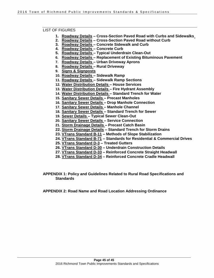
2 0 1 6 T o w n o f R i c h m o n d P u b l i c I m p r o v e m e n t s S t a n d a r d s & S p e c i f i c a t i o n s
Page 45 of 45 2016 Richmond Town Public Improvements Standards and Specifications
LIST OF FIGURES
1. Roadway Details – Cross-Section Paved Road with Curbs and Sidewalks 2. Roadway Details – Cross-Section Paved Road without Curb 3. Roadway Details – Concrete Sidewalk and Curb 4. Roadway Details – Concrete Curb 5. Roadway Details – Typical Underdrain Clean-Out
6. Roadway Details – Replacement of Existing Bituminous Pavement
7. Roadway Details – Urban Driveway Aprons
8. Roadway Details – Rural Driveway
9. Signs & Signposts
10. Roadway Details – Sidewalk Ramp
11. Roadway Details – Sidewalk Ramp Sections
12. Water Distribution Details – House Services
13. Water Distribution Details – Fire Hydrant Assembly
14. Water Distribution Details – Standard Trench for Water
15. Sanitary Sewer Details – Precast Manholes
16. Sanitary Sewer Details – Drop Manhole Connection
17. Sanitary Sewer Details – Manhole Channel
18. Sanitary Sewer Details – Standard Trench for Sewer
19. Sewer Details – Typical Sewer Clean-Out
20. Sanitary Sewer Details – Service Connection
21. Storm Drainage Details – Precast Catch Basin
22. Storm Drainage Details – Standard Trench for Storm Drains
23. VTrans Standard B-11 – Methods of Slope Stabilization
24. VTrans Standard B-71 – Standards for Residential & Commercial Drives
25. VTrans Standard D-3 – Treated Gutters
26. VTrans Standard D-30 – Underdrain Construction Details
27. VTrans Standard D-33 – Reinforced Concrete Straight Headwall
28. VTrans Standard D-34 – Reinforced Concrete Cradle Headwall
APPENDIX 1: Policy and Guidelines Related to Rural Road Specifications and
Standards APPENDIX 2: Road Name and Road Location Addressing Ordinance