ptr series - kuroda pneumatics ltd. actuators ptr series h36 parker hannifin corporation pneumatic...
TRANSCRIPT

H35 Parker Hannifin CorporationPneumatic DivisionWadsworth, Ohio www.parker.com/pneumatics
PR
N(A
)P
VW
RP
TR
B67
1H
P
H
PTR Series Pneumatic Rack & Pinion Rotary Actuator
ContentsFeatures ........................................................................... H36Ordering Information......................................................... H37Specifications ................................................................... H38Engineering Data ...................................................... H39-H40Dimensions ....................................................................... H41Mounting Options ............................................................. H42Shaft Options .................................................................... H43Port Locations ................................................................... H43Cushions and Bumpers .................................................... H44
Stroke Adjusters ............................................................... H453-Position Actuator ........................................................... H46Antibacklash Actuator ....................................................... H47Air / Oil Operation ............................................................. H48Flow Controls .................................................................... H49Shaft Seal Covers ............................................................. H49Fluorocarbon Seals .......................................................... H49Magnetic Piston and Sensors ........................................... H50Service Kits ...................................................................... H51
Rotary ActuatorsPTR Series
H36 Parker Hannifin CorporationPneumatic DivisionWadsworth, Ohio www.parker.com/pneumatics
A076
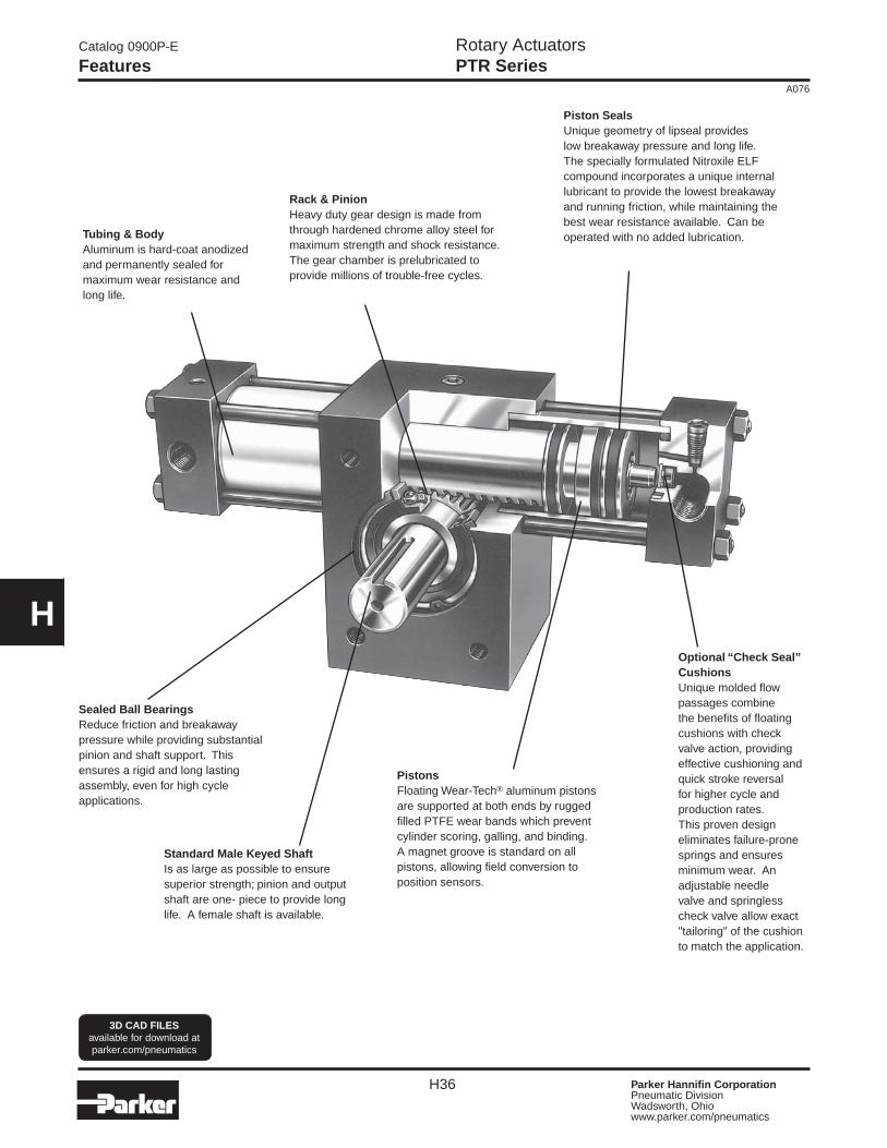
HOptional “Check Seal” Cushions Unique molded flow passages combine the benefits of floating cushions with check valve action, providing effective cushioning and quick stroke reversal for higher cycle and production rates. This proven design eliminates failure-prone springs and ensures minimum wear. An adjustable needle valve and springless check valve allow exact "tailoring" of the cushion to match the application.
Tubing & BodyAluminum is hard-coat anodized and permanently sealed for maximum wear resistance and long life.
Rack & Pinion Heavy duty gear design is made from through hardened chrome alloy steel for maximum strength and shock resistance. The gear chamber is prelubricated to provide millions of trouble-free cycles.
Sealed Ball Bearings Reduce friction and breakaway pressure while providing substantial pinion and shaft support. This ensures a rigid and long lasting assembly, even for high cycle applications.
Piston Seals Unique geometry of lipseal provides low breakaway pressure and long life. The specially formulated Nitroxile ELF compound incorporates a unique internal lubricant to provide the lowest breakaway and running friction, while maintaining the best wear resistance available. Can be operated with no added lubrication.
Standard Male Keyed Shaft Is as large as possible to ensure superior strength; pinion and output shaft are one- piece to provide long life. A female shaft is available.
Pistons Floating Wear-Tech® aluminum pistons are supported at both ends by rugged filled PTFE wear bands which prevent cylinder scoring, galling, and binding. A magnet groove is standard on all pistons, allowing field conversion to position sensors.
Catalog 0900P-E
Features
3D CAD FILESavailable for download at parker.com/pneumatics
Rotary ActuatorsPTR Series
H37 Parker Hannifin CorporationPneumatic DivisionWadsworth, Ohio www.parker.com/pneumatics
A076
PR
N(A
)P
VW
RP
TR
B67
1H
P
H
PTR
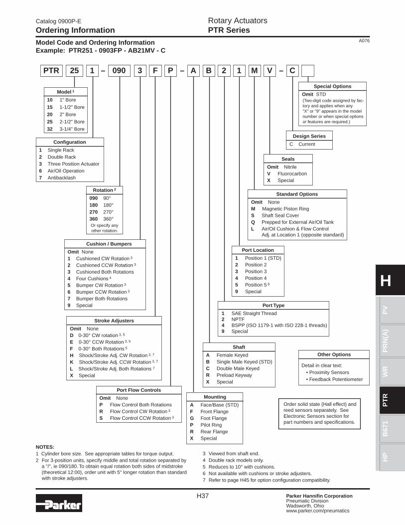
Configuration
1 Single Rack2 Double Rack3 Three Position Actuator6 Air/Oil Operation7 Antibacklash
Rotation 2
090 90°180 180°270 270°360 360°Or specify any other rotation.
Cushion / Bumpers
Omit None1 Cushioned CW Rotation 3
2 Cushioned CCW Rotation 3
3 Cushioned Both Rotations4 Four Cushions 4
5 Bumper CW Rotation 3
6 Bumper CCW Rotation 3
7 Bumper Both Rotations9 Special
Stroke Adjusters
Omit NoneD 0-30° CW rotation 3, 5
E 0-30° CCW Rotation 3, 5
F 0-30° Both Rotations 5
H Shock/Stroke Adj. CW Rotation 3, 7
K Shock/Stroke Adj. CCW Rotation 3, 7
L Shock/Stroke Adj. Both Rotations 7
X Special
Port Flow Controls
Omit NoneP Flow Control Both RotationsR Flow Control CW Rotation 3
S Flow Control CCW Rotation 3
Shaft
A Female KeyedB Single Male Keyed (STD)C Double Male KeyedR Preload KeywayX Special
Port Location
1 Position 1 (STD)2 Position 2 3 Position 34 Position 45 Position 5 6
9 Special
Seals
Omit Nitrile V FluorocarbonX Special
NOTES:1 Cylinder bore size. See appropriate tables for torque output. 2 For 3-position units, specify middle and total rotation separated by
a "/", ie 090/180. To obtain equal rotation both sides of midstroke (theoretical 12:00), order unit with 5° longer rotation than standard with stroke adjusters.
Model 1
10 1" Bore
15 1-1/2" Bore
20 2" Bore
25 2-1/2" Bore
32 3-1/4" Bore
Port Type
1 SAE Straight Thread2 NPTF4 BSPP (ISO 1179-1 with ISO 228-1 threads)9 Special
Mounting
A Face/Base (STD)F Front Flange G Foot FlangeP Pilot RingR Rear FlangeX Special
Standard Options
Omit NoneM Magnetic Piston RingS Shaft Seal CoverQ Prepped for External Air/Oil TankL Air/Oil Cushion & Flow Control Adj. at Location 1 (opposite standard)
Catalog 0900P-E
Ordering Information
Model Code and Ordering InformationExample: PTR251 - 0903FP - AB21MV - C
25 1 090 3 F P– – A B 2 1 M V – C
Other Options
Detail in clear text: • Proximity Sensors • Feedback Potentiometer
Design Series
C Current
Special Options
Omit STD(Two-digit code assigned by fac-tory and applies when any "X" or "9" appears in the model number or when special options or features are required.)
3 Viewed from shaft end.4 Double rack models only.5 Reduces to 10° with cushions.6 Not available with cushions or stroke adjusters.7 Refer to page H45 for option configuration compatibility.
Order solid state (Hall effect) and reed sensors separately. See Electronic Sensors section for part numbers and specifications.
Rotary ActuatorsPTR Series
H38 Parker Hannifin CorporationPneumatic DivisionWadsworth, Ohio www.parker.com/pneumatics
A076
H
Catalog 0900P-E
Specifications
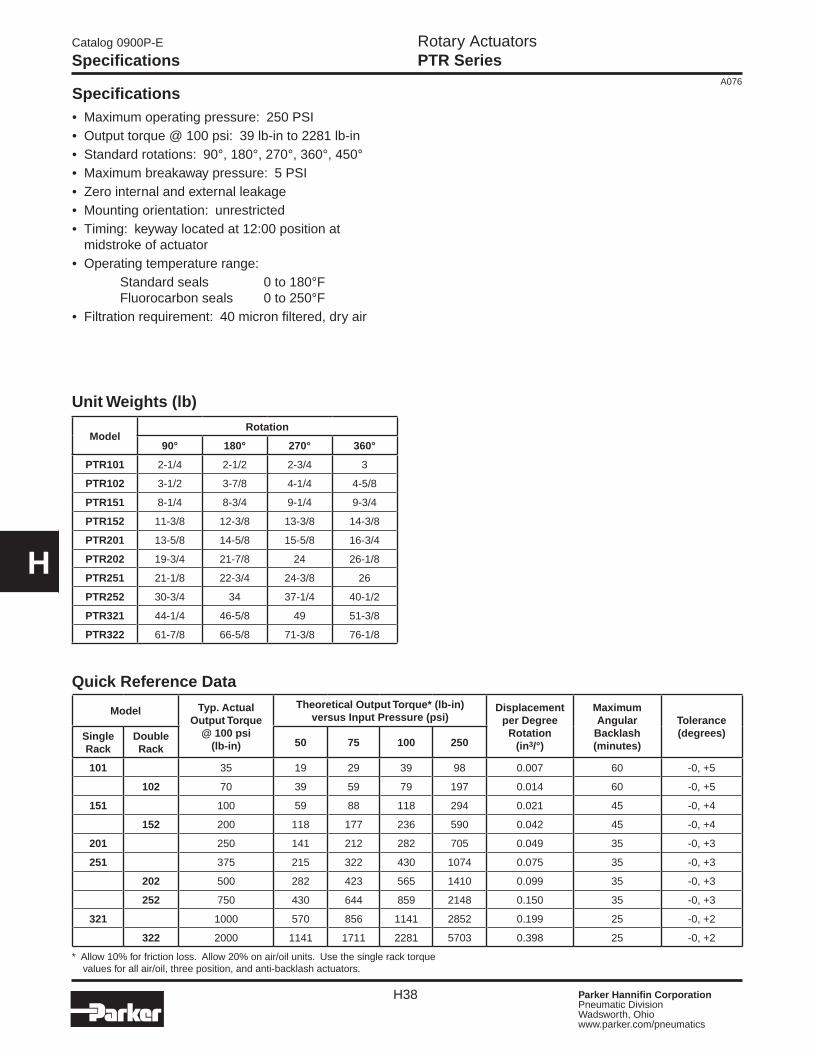
Specifications• Maximum operating pressure: 250 PSI• Output torque @ 100 psi: 39 lb-in to 2281 lb-in• Standard rotations: 90°, 180°, 270°, 360°, 450°• Maximum breakaway pressure: 5 PSI • Zero internal and external leakage• Mounting orientation: unrestricted• Timing: keyway located at 12:00 position at midstroke of actuator• Operating temperature range: Standard seals 0 to 180°F Fluorocarbon seals 0 to 250°F• Filtration requirement: 40 micron filtered, dry air
Model Typ. Actual Output Torque
@ 100 psi(lb-in)
Theoretical Output Torque* (lb-in)versus Input Pressure (psi)
Displacement per Degree
Rotation (in3/°)
Maximum Angular
Backlash(minutes)
Tolerance(degrees)Single
RackDouble Rack
50 75 100 250
101 35 19 29 39 98 0.007 60 -0, +5
102 70 39 59 79 197 0.014 60 -0, +5
151 100 59 88 118 294 0.021 45 -0, +4
152 200 118 177 236 590 0.042 45 -0, +4
201 250 141 212 282 705 0.049 35 -0, +3
251 375 215 322 430 1074 0.075 35 -0, +3
202 500 282 423 565 1410 0.099 35 -0, +3
252 750 430 644 859 2148 0.150 35 -0, +3
321 1000 570 856 1141 2852 0.199 25 -0, +2
322 2000 1141 1711 2281 5703 0.398 25 -0, +2
* Allow 10% for friction loss. Allow 20% on air/oil units. Use the single rack torque values for all air/oil, three position, and anti-backlash actuators.
Quick Reference Data
Unit Weights (lb)
ModelRotation
90° 180° 270° 360°
PTR101 2-1/4 2-1/2 2-3/4 3
PTR102 3-1/2 3-7/8 4-1/4 4-5/8
PTR151 8-1/4 8-3/4 9-1/4 9-3/4
PTR152 11-3/8 12-3/8 13-3/8 14-3/8
PTR201 13-5/8 14-5/8 15-5/8 16-3/4
PTR202 19-3/4 21-7/8 24 26-1/8
PTR251 21-1/8 22-3/4 24-3/8 26
PTR252 30-3/4 34 37-1/4 40-1/2
PTR321 44-1/4 46-5/8 49 51-3/8
PTR322 61-7/8 66-5/8 71-3/8 76-1/8
Rotary ActuatorsPTR Series
H39 Parker Hannifin CorporationPneumatic DivisionWadsworth, Ohio www.parker.com/pneumatics
A076
PR
N(A
)P
VW
RP
TR
B67
1H
P
H
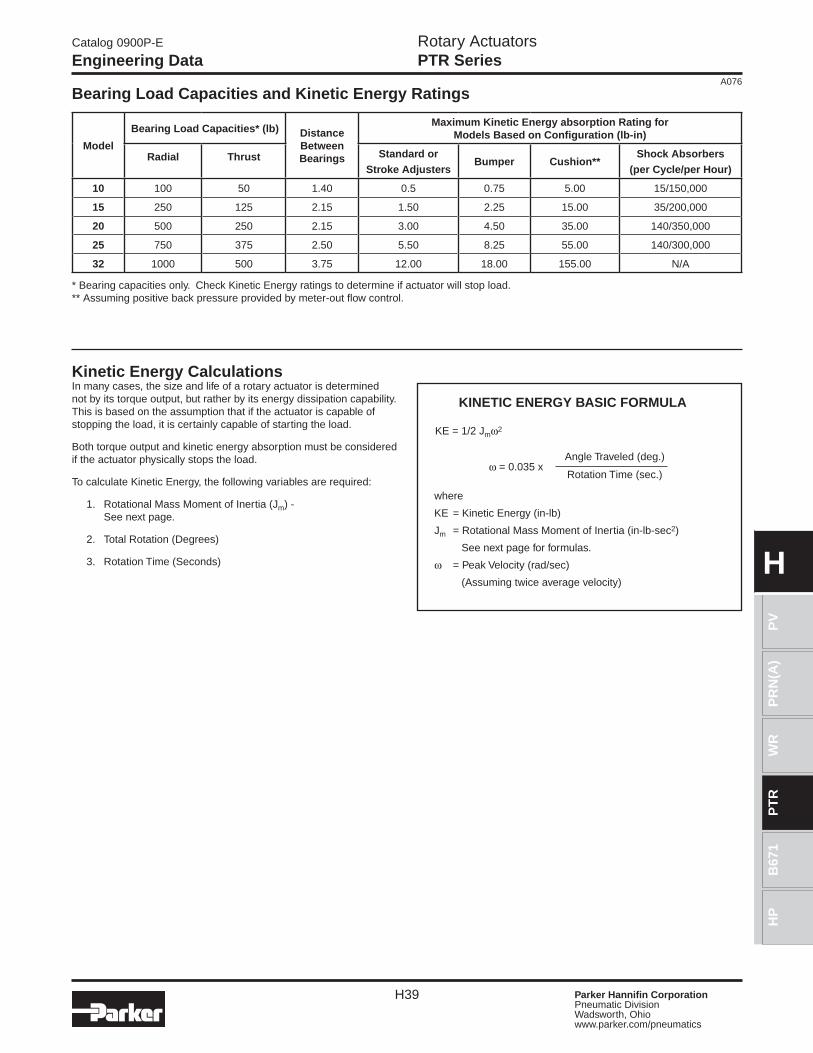
KINETIC ENERGY BASIC FORMULA
KE = 1/2 Jmω2
ω = 0.035 x
Model
Bearing Load Capacities* (lb) Distance BetweenBearings
Maximum Kinetic Energy absorption Rating forModels Based on Configuration (lb-in)
Radial Thrust Standard orStroke Adjusters
Bumper Cushion**Shock Absorbers
(per Cycle/per Hour)
10 100 50 1.40 0.5 0.75 5.00 15/150,000
15 250 125 2.15 1.50 2.25 15.00 35/200,000
20 500 250 2.15 3.00 4.50 35.00 140/350,000
25 750 375 2.50 5.50 8.25 55.00 140/300,000
32 1000 500 3.75 12.00 18.00 155.00 N/A
Bearing Load Capacities and Kinetic Energy Ratings
* Bearing capacities only. Check Kinetic Energy ratings to determine if actuator will stop load.** Assuming positive back pressure provided by meter-out flow control.
Angle Traveled (deg.)
Rotation Time (sec.)
Kinetic Energy CalculationsIn many cases, the size and life of a rotary actuator is determined not by its torque output, but rather by its energy dissipation capability. This is based on the assumption that if the actuator is capable of stopping the load, it is certainly capable of starting the load.
Both torque output and kinetic energy absorption must be considered if the actuator physically stops the load.
To calculate Kinetic Energy, the following variables are required:
1. Rotational Mass Moment of Inertia (Jm) - See next page.
2. Total Rotation (Degrees)
3. Rotation Time (Seconds)
where
KE = Kinetic Energy (in-lb)
Jm = Rotational Mass Moment of Inertia (in-lb-sec2)
See next page for formulas.
ω = Peak Velocity (rad/sec)
(Assuming twice average velocity)
Catalog 0900P-E
Engineering Data
Rotary ActuatorsPTR Series
H40 Parker Hannifin CorporationPneumatic DivisionWadsworth, Ohio www.parker.com/pneumatics
A076
H
SOLID SPHERE -Mounted on center
THIN DISK-End mounted on center
POINT LOAD
THIN RECTANGULAR PLATE -Mounted on center
THIN RECTANGULAR PLATE -Mounted off center
THIN DISK-Mounted on center
SLENDER ROD -Mounted off center
THIN RECTANGULAR PLATE-End mounted on center
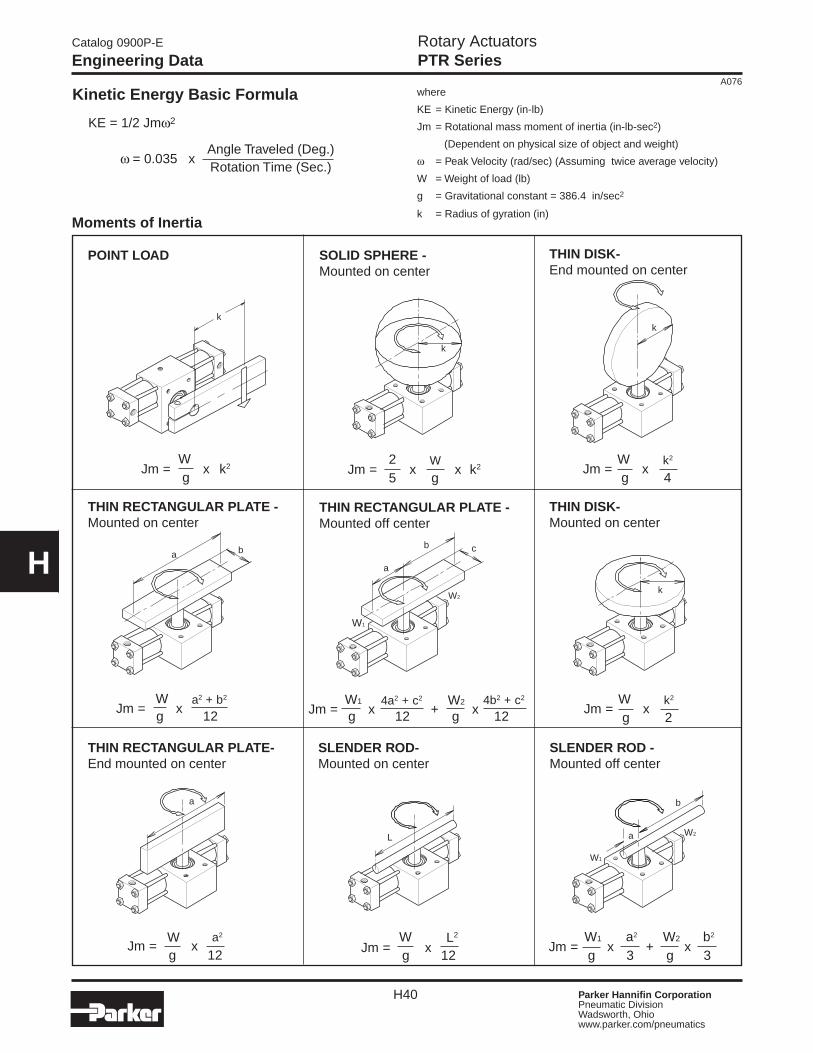
Moments of Inertia
Kinetic Energy Basic Formula
KE = 1/2 Jmω2
ω= 0.035 x
Angle Traveled (Deg.)Rotation Time (Sec.)
where
KE = Kinetic Energy (in-lb)
Jm = Rotational mass moment of inertia (in-lb-sec2)
(Dependent on physical size of object and weight)
ω = Peak Velocity (rad/sec) (Assuming twice average velocity)
W = Weight of load (lb)
g = Gravitational constant = 386.4 in/sec2
k = Radius of gyration (in)
SLENDER ROD-Mounted on center
Jm = x + x4a2 + c2 W2
Jm = xa2 + b2 W
g 2k2
Jm = x
Wg 4
k2
Jm = x5 g
WJm = x x k2
Wg
Jm = x k22
W W1 4b2 + c2
g 12Jm = x
L2WW a2
Jm = xg 12
W1 a2 W2 b2
Jm = x + xg 3 g 3
g 12 g 12g 12
k
k
a
a
b
W2
W1
k
b
a
c
W2
W1
ba
L
k
Catalog 0900P-E
Engineering Data
Rotary ActuatorsPTR Series
H41 Parker Hannifin CorporationPneumatic DivisionWadsworth, Ohio www.parker.com/pneumatics
A076
PR
N(A
)P
VW
RP
TR
B67
1H
P
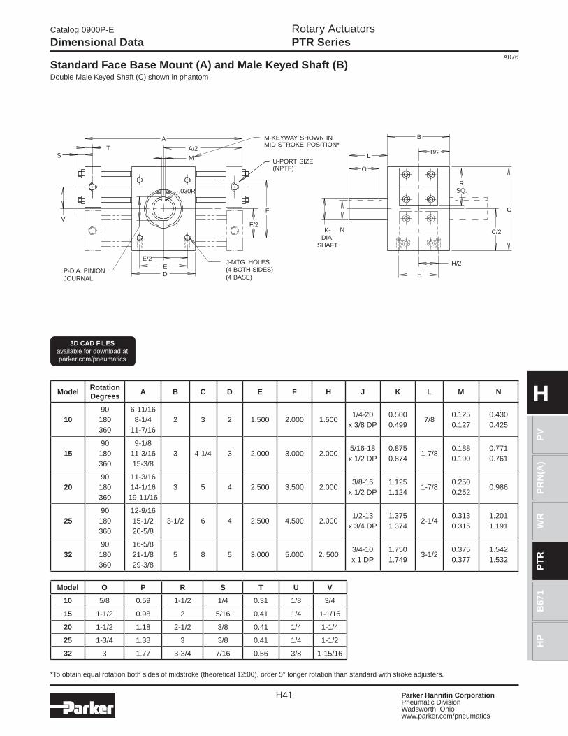
HModelRotationDegrees
A B C D E F H J K L M N
1090
180360
6-11/168-1/4
11-7/162 3 2 1.500 2.000 1.500
1/4-20x 3/8 DP
0.5000.499
7/80.1250.127
0.4300.425
1590
180360
9-1/811-3/1615-3/8
3 4-1/4 3 2.000 3.000 2.0005/16-18x 1/2 DP
0.8750.874
1-7/80.1880.190
0.7710.761
2090
180360
11-3/1614-1/16
19-11/163 5 4 2.500 3.500 2.000
3/8-16x 1/2 DP
1.1251.124
1-7/80.2500.252
0.986
2590
180360
12-9/1615-1/220-5/8
3-1/2 6 4 2.500 4.500 2.0001/2-13
x 3/4 DP1.3751.374
2-1/40.3130.315
1.2011.191
3290
180360
16-5/821-1/829-3/8
5 8 5 3.000 5.000 2. 5003/4-10x 1 DP
1.7501.749
3-1/20.3750.377
1.5421.532
Model O P R S T U V
10 5/8 0.59 1-1/2 1/4 0.31 1/8 3/4
15 1-1/2 0.98 2 5/16 0.41 1/4 1-1/16
20 1-1/2 1.18 2-1/2 3/8 0.41 1/4 1-1/4
25 1-3/4 1.38 3 3/8 0.41 1/4 1-1/2
32 3 1.77 3-3/4 7/16 0.56 3/8 1-15/16
Standard Face Base Mount (A) and Male Keyed Shaft (B)Double Male Keyed Shaft (C) shown in phantom
*To obtain equal rotation both sides of midstroke (theoretical 12:00), order 5° longer rotation than standard with stroke adjusters.
3D CAD FILESavailable for download at parker.com/pneumatics
K-DIA.
SHAFT
H
U-PORT SIZE(NPTF)
F/2
F
A/2
M
TS
E/2
DE
A
N
O
L
B
B/2
RSQ.
H/2
C/2
C
.030R
P-DIA. PINIONJOURNAL
J-MTG. HOLES(4 BOTH SIDES)(4 BASE)
M-KEYWAY SHOWN INMID-STROKE POSITION*
V
Catalog 0900P-E
Dimensional Data
Rotary ActuatorsPTR Series
H42 Parker Hannifin CorporationPneumatic DivisionWadsworth, Ohio www.parker.com/pneumatics
A076
H
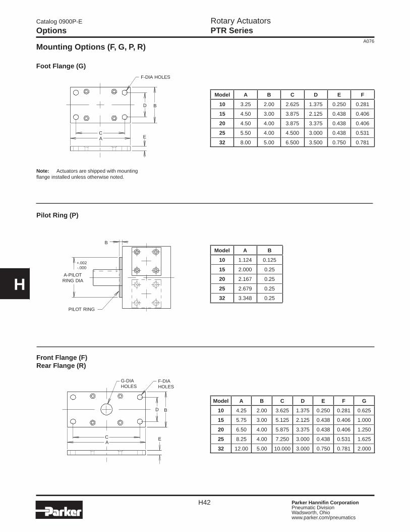
Mounting Options (F, G, P, R)
Note: Actuators are shipped with mounting flange installed unless otherwise noted.
Model A B C D E F
10 3.25 2.00 2.625 1.375 0.250 0.281
15 4.50 3.00 3.875 2.125 0.438 0.406
20 4.50 4.00 3.875 3.375 0.438 0.406
25 5.50 4.00 4.500 3.000 0.438 0.531
32 8.00 5.00 6.500 3.500 0.750 0.781
Model A B
10 1.124 0.125
15 2.000 0.25
20 2.167 0.25
25 2.679 0.25
32 3.348 0.25
Front Flange (F)Rear Flange (R)
Pilot Ring (P)
Foot Flange (G)
BD
F-DIA HOLES
AC
E
A-PILOTRING DIA
PILOT RING
+.002-.000
B
A
BD
E
G-DIAHOLES
F-DIAHOLES
C
Model A B C D E F G
10 4.25 2.00 3.625 1.375 0.250 0.281 0.625
15 5.75 3.00 5.125 2.125 0.438 0.406 1.000
20 6.50 4.00 5.875 3.375 0.438 0.406 1.250
25 8.25 4.00 7.250 3.000 0.438 0.531 1.625
32 12.00 5.00 10.000 3.000 0.750 0.781 2.000
Catalog 0900P-E
Options
Rotary ActuatorsPTR Series
H43 Parker Hannifin CorporationPneumatic DivisionWadsworth, Ohio www.parker.com/pneumatics
A076
PR
N(A
)P
VW
RP
TR
B67
1H
P
H
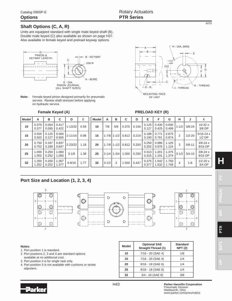
Shaft Options (C, A, R)Units are equipped standard with single male keyed shaft (B). Double male keyed (C) also available as shown on page H37. Also available in female keyed and preload keyway options.
Female Keyed (A)
Model A B C D E
100.3750.377
0.0930.095
0.4170.422
1-13/32 0.59
150.5000.502
0.1250.127
0.5600.565
2-11/16 0.98
200.7500.752
0.1870.189
0.8370.847
2-23/32 1.18
251.0001.002
0.2500.252
1.0831.093
3-1/8 1.38
321.2501.252
0.2500.252
1.3671.377
4-9/16 1.77
PRELOAD KEY (R)
Model A B C D E F G H J K
10 7/8 5/8 0.375 0.1560.1250.127
0.4300.425
0.5000.499
1-1/2 3/8-2410-32 x3/8 DP
15 1-7/8 1-1/2 0.812 0.2190.1880.190
0.7710.761
0.8750.874
2 1/2-205/16-24 x
1/2 DP
20 1-7/8 1-1/2 0.812 0.2500.2500.252
0.9860.976
1.1251.124
3 5/8-113/8-24 x9/16 DP
25 2-1/4 1-3/4 1.000 0.2500.3130.315
1.2011.191
1.3751.374
3-1/2 3/4-103/8-24 x9/16 DP
32 3-1/2 3 1.500 0.4370.3750.377
1.5421.532
1.7501.749
4 1-81/2-20 x3/4 DP
Note: Female keyed pinion designed primarily for pneumatic service. Review shaft stresses before applying on hydraulic service.
DPINION &
KEYWAY LENGTHC
B - KEYWAY
A - BORE
.030 R
E - DIA.PINION JOURNAL
(ALL SHAFT SIZES)
A
B
H - DIA. (MIN)
E
J - THREADK - THREAD
G/2
D - R.
MOUNTING FACEOF UNIT
C
+.010–.000
FG
Port Size and Location (1, 2, 3, 4)
Notes: 1. Port position 1 is standard.2. Port positions 2, 3 and 4 are standard options
available at no additional cost.3. Port position 4 is for single rack only.4, Port position 5 is not available with cushions or stroke
adjusters.
ModelOptional SAE
Straight Thread (1)Standard NPT (2)
10 7/16 - 20 (SAE 4) 1/8
15 7/16 - 20 (SAE 4) 1/4
20 9/16 - 18 (SAE 6) 1/4
25 9/16 - 18 (SAE 6) 1/4
32 3/4 - 16 (SAE 8) 3/8
2
31
1 3
2
4
1
1
4
2
3
3
2
5
5
5
5
Catalog 0900P-E
Options
Rotary ActuatorsPTR Series
H44 Parker Hannifin CorporationPneumatic DivisionWadsworth, Ohio www.parker.com/pneumatics
A076
H
Catalog 0900P-E
Options
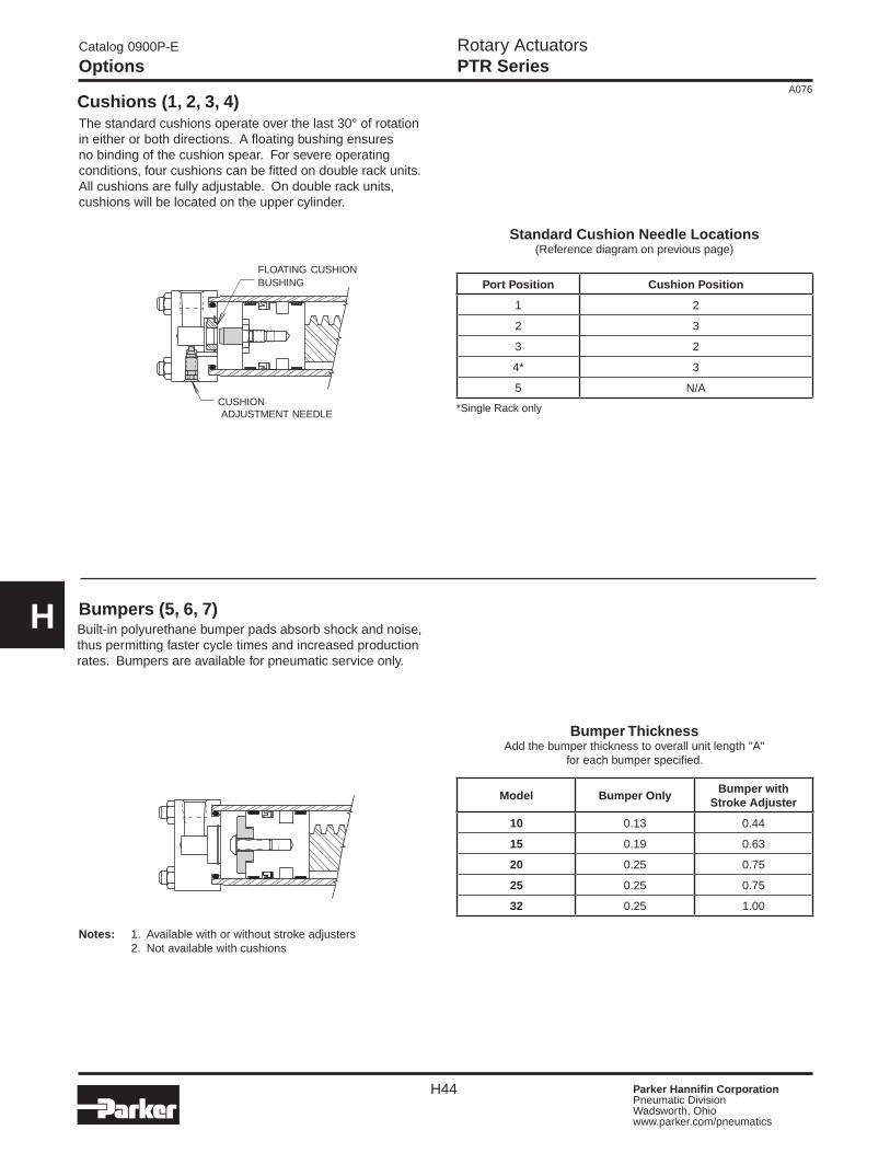
Cushions (1, 2, 3, 4)
Standard Cushion Needle Locations(Reference diagram on previous page)
Port Position Cushion Position
1 2
2 3
3 2
4* 3
5 N/A
*Single Rack only
Notes: 1. Available with or without stroke adjusters 2. Not available with cushions
Bumpers (5, 6, 7)Built-in polyurethane bumper pads absorb shock and noise, thus permitting faster cycle times and increased production rates. Bumpers are available for pneumatic service only.
The standard cushions operate over the last 30° of rotation in either or both directions. A floating bushing ensures no binding of the cushion spear. For severe operating conditions, four cushions can be fitted on double rack units. All cushions are fully adjustable. On double rack units, cushions will be located on the upper cylinder.
CUSHION ADJUSTMENT NEEDLE
FLOATING CUSHIONBUSHING
Bumper ThicknessAdd the bumper thickness to overall unit length "A"
for each bumper specified.
Model Bumper OnlyBumper with
Stroke Adjuster
10 0.13 0.44
15 0.19 0.63
20 0.25 0.75
25 0.25 0.75
32 0.25 1.00
Rotary ActuatorsPTR Series
H45 Parker Hannifin CorporationPneumatic DivisionWadsworth, Ohio www.parker.com/pneumatics
A076
PR
N(A
)P
VW
RP
TR
B67
1H
P
H
Catalog 0900P-E
Options
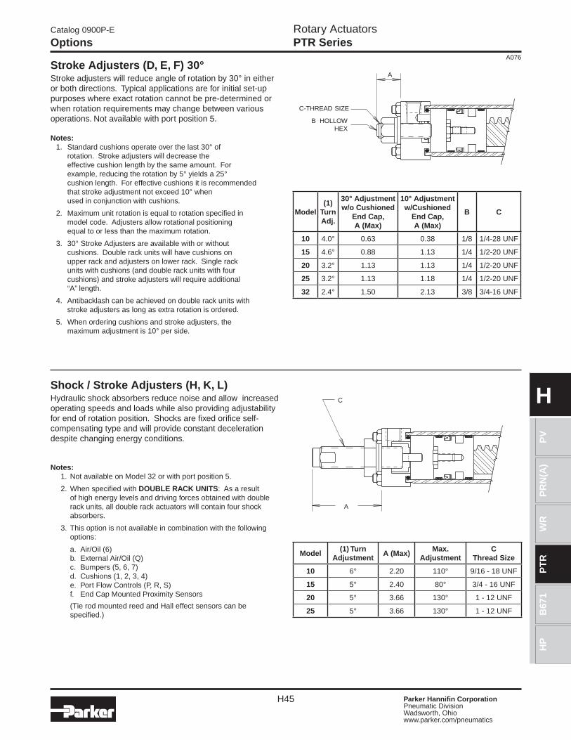
Stroke Adjusters (D, E, F) 30°Stroke adjusters will reduce angle of rotation by 30° in either or both directions. Typical applications are for initial set-up purposes where exact rotation cannot be pre-determined or when rotation requirements may change between various operations. Not available with port position 5.
Notes: 1. Standard cushions operate over the last 30° of
rotation. Stroke adjusters will decrease the effective cushion length by the same amount. For example, reducing the rotation by 5° yields a 25° cushion length. For effective cushions it is recommended that stroke adjustment not exceed 10° when used in conjunction with cushions.
2. Maximum unit rotation is equal to rotation specified in model code. Adjusters allow rotational positioning equal to or less than the maximum rotation.
3. 30° Stroke Adjusters are available with or without cushions. Double rack units will have cushions on upper rack and adjusters on lower rack. Single rack units with cushions (and double rack units with four cushions) and stroke adjusters will require additional “A” length.
4. Antibacklash can be achieved on double rack units with stroke adjusters as long as extra rotation is ordered.
5. When ordering cushions and stroke adjusters, the maximum adjustment is 10° per side.
Shock / Stroke Adjusters (H, K, L)Hydraulic shock absorbers reduce noise and allow increased operating speeds and loads while also providing adjustability for end of rotation position. Shocks are fixed orifice self-compensating type and will provide constant deceleration despite changing energy conditions.
Notes: 1. Not available on Model 32 or with port position 5.
2. When specified with DOUBLE RACK UNITS: As a result of high energy levels and driving forces obtained with double rack units, all double rack actuators will contain four shock absorbers.
3. This option is not available in combination with the following options:
a. Air/Oil (6) b. External Air/Oil (Q) c. Bumpers (5, 6, 7) d. Cushions (1, 2, 3, 4) e. Port Flow Controls (P, R, S) f. End Cap Mounted Proximity Sensors
(Tie rod mounted reed and Hall effect sensors can be specified.)
Model(1)
TurnAdj.
30° Adjustmentw/o Cushioned
End Cap,A (Max)
10° Adjustmentw/Cushioned
End Cap,A (Max)
B C
10 4.0° 0.63 0.38 1/8 1/4-28 UNF
15 4.6° 0.88 1.13 1/4 1/2-20 UNF
20 3.2° 1.13 1.13 1/4 1/2-20 UNF
25 3.2° 1.13 1.18 1/4 1/2-20 UNF
32 2.4° 1.50 2.13 3/8 3/4-16 UNF
Model(1) Turn
AdjustmentA (Max)
Max.Adjustment
CThread Size
10 6° 2.20 110° 9/16 - 18 UNF
15 5° 2.40 80° 3/4 - 16 UNF
20 5° 3.66 130° 1 - 12 UNF
25 5° 3.66 130° 1 - 12 UNF
C-THREAD SIZE
B HOLLOWHEX
A
C
A
Rotary ActuatorsPTR Series
H46 Parker Hannifin CorporationPneumatic DivisionWadsworth, Ohio www.parker.com/pneumatics
A076
H
Catalog 0900P-E
Options
POS. B
POS. A POS. C
C-3 C-4
C-1C-2
STOP TUBE
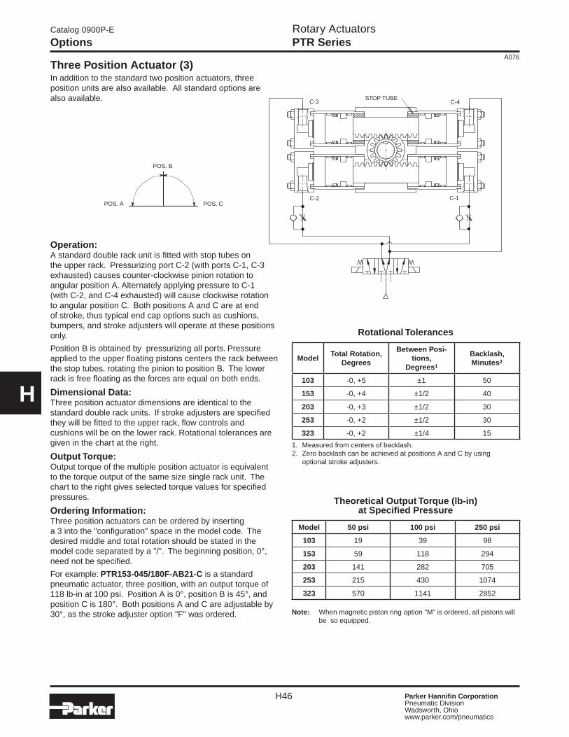
Three Position Actuator (3)In addition to the standard two position actuators, three position units are also available. All standard options are also available.
Operation:A standard double rack unit is fitted with stop tubes on the upper rack. Pressurizing port C-2 (with ports C-1, C-3 exhausted) causes counter-clockwise pinion rotation to angular position A. Alternately applying pressure to C-1 (with C-2, and C-4 exhausted) will cause clockwise rotation to angular position C. Both positions A and C are at end of stroke, thus typical end cap options such as cushions, bumpers, and stroke adjusters will operate at these positions only.
Position B is obtained by pressurizing all ports. Pressure applied to the upper floating pistons centers the rack between the stop tubes, rotating the pinion to position B. The lower rack is free floating as the forces are equal on both ends.
Dimensional Data:Three position actuator dimensions are identical to the standard double rack units. If stroke adjusters are specified they will be fitted to the upper rack, flow controls and cushions will be on the lower rack. Rotational tolerances are given in the chart at the right.
Output Torque:Output torque of the multiple position actuator is equivalent to the torque output of the same size single rack unit. The chart to the right gives selected torque values for specified pressures.
Ordering Information:Three position actuators can be ordered by inserting a 3 into the "configuration" space in the model code. The desired middle and total rotation should be stated in the model code separated by a "/". The beginning position, 0°, need not be specified.
For example: PTR153-045/180F-AB21-C is a standard pneumatic actuator, three position, with an output torque of 118 lb-in at 100 psi. Position A is 0°, position B is 45°, and position C is 180°. Both positions A and C are adjustable by 30°, as the stroke adjuster option "F" was ordered.
Rotational Tolerances
ModelTotal Rotation,
Degrees
Between Posi-tions,
Degrees1
Backlash,Minutes2
103 -0, +5 ±1 50
153 -0, +4 ±1/2 40
203 -0, +3 ±1/2 30
253 -0, +2 ±1/2 30
323 -0, +2 ±1/4 15
1. Measured from centers of backlash.2. Zero backlash can be achieved at positions A and C by using optional stroke adjusters.
Theoretical Output Torque (lb-in)at Specified Pressure
Model 50 psi 100 psi 250 psi
103 19 39 98
153 59 118 294
203 141 282 705
253 215 430 1074
323 570 1141 2852
Note: When magnetic piston ring option "M" is ordered, all pistons will be so equipped.

Rotary ActuatorsPTR Series
H47 Parker Hannifin CorporationPneumatic DivisionWadsworth, Ohio www.parker.com/pneumatics
A076
PR
N(A
)P
VW
RP
TR
B67
1H
P
H
Catalog 0900P-E
Options
Antibacklash Actuator (7)An antibacklash actuator is used to obtain precision positioning at the end of rotation. The backlash normally associated with rack and pinion actuators is eliminated by this unique configuration.
Operation:A double rack unit is modified for actuation on one end only.
Alternately pressurizing C-1 or C-2 causes clockwise and counter-clockwise rotation, respectively. Backlash in the rack & pinion is eliminated as the pinion is tightly "trapped" between both racks at the end of stroke, preventing any further motion.
Dimensional Data:Antibacklash actuators are similar in size and configuration to standard double rack units with one set of shorter cylinders. The table to the right shows dimensions for this shorter side. If cushions, stroke adjusters or port flow controls are ordered, they will be fitted to the powered rack side.
Output Torque:Output torque of the antibacklash actuator is equivalent to the torque output of the same size single rack unit. The chart to the right gives selected torque valves for specified pressures.
Ordering Information:Antibacklash actuators can be ordered by inserting a "7" into the "configuration" space in the model code. For example: PTR157-180F-AR21-C is a pneumatic antibacklash actuator with a theoretical output torque of 118 lb-in at 100 psi.
The optional stroke adjusters make the rotation variable between 120° and 180°. The preload key option on the shaft is also specified to eliminate any backlash in the key and coupling interface.
Note: Antibacklash can also be obtained on double rack actuators by implementing stroke adjusters at end of stroke. This will enable you to maintain double rack output torque.
Dimensions
Model Rotation A B
107
90° 3-3/4 2-3/4
180° 4-1/8 3-3/4
360° 5-3/4 5
157
90° 4-9/16 3-5/16
180° 5-5/8 4-9/16
360° 7-11/16 6-5/8
207
90° 5-5/8 4-1/8
180° 7-1/16 5-5/8
360° 9-7/8 8-1/2
257
90° 6-5/16 4-3/8
180° 7-3/4 6-5/16
360° 10-5/16 8-13/16
327
90° 8-5/16 5-13/16
180° 10-9/16 8-5/16
360° 14-11/16 12-7/16
Theoretical Output Torque, lb-in, at Specified Pressure
Model 50 psi 100 psi 250 psi
107 19 39 98
157 59 118 294
207 141 282 705
257 215 430 1074
327 570 1141 2852
C-1
C-2
BA
Rotary ActuatorsPTR Series
H48 Parker Hannifin CorporationPneumatic DivisionWadsworth, Ohio www.parker.com/pneumatics
A076
H
Catalog 0900P-E
Options
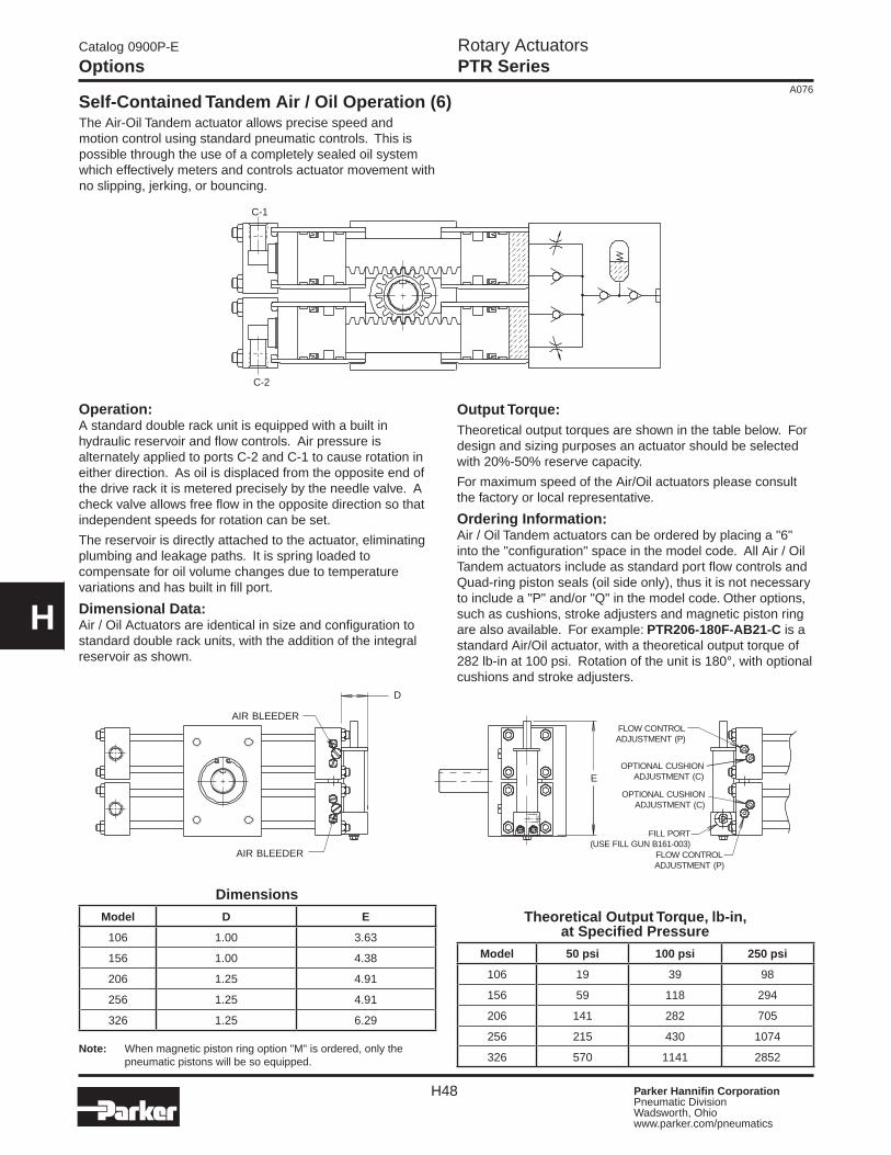
Output Torque:Theoretical output torques are shown in the table below. For design and sizing purposes an actuator should be selected with 20%-50% reserve capacity.
For maximum speed of the Air/Oil actuators please consult the factory or local representative.
Ordering Information:Air / Oil Tandem actuators can be ordered by placing a "6" into the "configuration" space in the model code. All Air / Oil Tandem actuators include as standard port flow controls and Quad-ring piston seals (oil side only), thus it is not necessary to include a "P" and/or "Q" in the model code. Other options, such as cushions, stroke adjusters and magnetic piston ring are also available. For example: PTR206-180F-AB21-C is a standard Air/Oil actuator, with a theoretical output torque of 282 lb-in at 100 psi. Rotation of the unit is 180°, with optional cushions and stroke adjusters.
Operation:A standard double rack unit is equipped with a built in hydraulic reservoir and flow controls. Air pressure is alternately applied to ports C-2 and C-1 to cause rotation in either direction. As oil is displaced from the opposite end of the drive rack it is metered precisely by the needle valve. A check valve allows free flow in the opposite direction so that independent speeds for rotation can be set.
The reservoir is directly attached to the actuator, eliminating plumbing and leakage paths. It is spring loaded to compensate for oil volume changes due to temperature variations and has built in fill port.
Dimensional Data:Air / Oil Actuators are identical in size and configuration to standard double rack units, with the addition of the integral reservoir as shown.
The Air-Oil Tandem actuator allows precise speed and motion control using standard pneumatic controls. This is possible through the use of a completely sealed oil system which effectively meters and controls actuator movement with no slipping, jerking, or bouncing.
Theoretical Output Torque, lb-in, at Specified Pressure
Model 50 psi 100 psi 250 psi
106 19 39 98
156 59 118 294
206 141 282 705
256 215 430 1074
326 570 1141 2852Note: When magnetic piston ring option "M" is ordered, only the
pneumatic pistons will be so equipped.
DimensionsModel D E
106 1.00 3.63
156 1.00 4.38
206 1.25 4.91
256 1.25 4.91
326 1.25 6.29
Self-Contained Tandem Air / Oil Operation (6)
C-1
C-2
D
AIR BLEEDER
FILL PORT(USE FILL GUN B161-003)
FLOW CONTROLADJUSTMENT (P)
OPTIONAL CUSHIONADJUSTMENT (C)
FLOW CONTROLADJUSTMENT (P)
OPTIONAL CUSHIONADJUSTMENT (C)E
AIR BLEEDER
Rotary ActuatorsPTR Series
H49 Parker Hannifin CorporationPneumatic DivisionWadsworth, Ohio www.parker.com/pneumatics
A076
PR
N(A
)P
VW
RP
TR
B67
1H
P
H
Catalog 0900P-E
Options
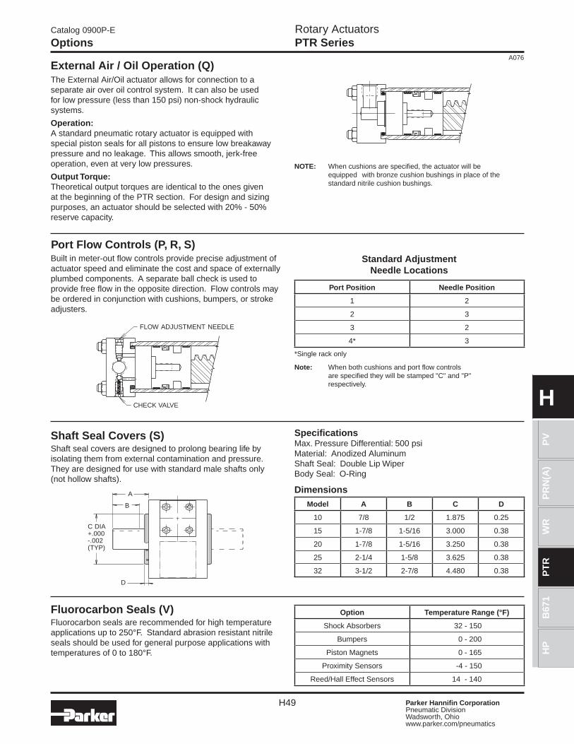
External Air / Oil Operation (Q)
NOTE: When cushions are specified, the actuator will be equipped with bronze cushion bushings in place of the standard nitrile cushion bushings.
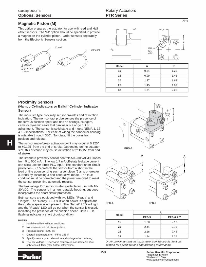
Port Flow Controls (P, R, S)Standard Adjustment
Needle Locations
Port Position Needle Position
1 2
2 3
3 2
4* 3
*Single rack only
Note: When both cushions and port flow controls are specified they will be stamped "C" and "P" respectively.
The External Air/Oil actuator allows for connection to a separate air over oil control system. It can also be used for low pressure (less than 150 psi) non-shock hydraulic systems.
Operation:A standard pneumatic rotary actuator is equipped with special piston seals for all pistons to ensure low breakaway pressure and no leakage. This allows smooth, jerk-free operation, even at very low pressures.
Output Torque:Theoretical output torques are identical to the ones given at the beginning of the PTR section. For design and sizing purposes, an actuator should be selected with 20% - 50% reserve capacity.
Built in meter-out flow controls provide precise adjustment of actuator speed and eliminate the cost and space of externally plumbed components. A separate ball check is used to provide free flow in the opposite direction. Flow controls may be ordered in conjunction with cushions, bumpers, or stroke adjusters.
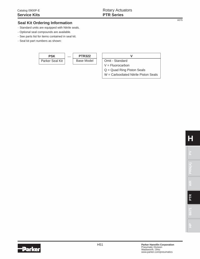
Shaft Seal Covers (S)Shaft seal covers are designed to prolong bearing life by isolating them from external contamination and pressure. They are designed for use with standard male shafts only (not hollow shafts).
DimensionsModel A B C D
10 7/8 1/2 1.875 0.25
15 1-7/8 1-5/16 3.000 0.38
20 1-7/8 1-5/16 3.250 0.38
25 2-1/4 1-5/8 3.625 0.38
32 3-1/2 2-7/8 4.480 0.38
Fluorocarbon Seals (V)Fluorocarbon seals are recommended for high temperature applications up to 250°F. Standard abrasion resistant nitrile seals should be used for general purpose applications with temperatures of 0 to 180°F.
Option Temperature Range (°F)
Shock Absorbers 32 - 150
Bumpers 0 - 200
Piston Magnets 0 - 165
Proximity Sensors -4 - 150
Reed/Hall Effect Sensors 14 - 140
FLOW ADJUSTMENT NEEDLE
CHECK VALVE
SpecificationsMax. Pressure Differential: 500 psi Material: Anodized Aluminum Shaft Seal: Double Lip Wiper Body Seal: O-Ring
B
A
D
C DIA+.000-.002(TYP)
Rotary ActuatorsPTR Series
H50 Parker Hannifin CorporationPneumatic DivisionWadsworth, Ohio www.parker.com/pneumatics
A076
H
Catalog 0900P-E
Options, Sensors
ModelA
EPS-5 EPS-6 & 7
15 1.88 2.17
20 2.44 2.75
25 2.16 2.48
32 1.94 2.25
1 BROWN
4 BLACK
6"cord
3 BLUE
39"Cord
1.00 A
1/16INT.HEX
B
Model A B
10 0.84 1.22
15 0.99 1.46
20 1.27 1.68
25 1.45 1.89
32 1.71 2.20
The inductive type proximity sensor provides end of rotation indication. The non-contact probe senses the presence of the ferrous cushion spear and has no springs, plungers, cams or dynamic seals that can wear out or go out of adjustment. The sensor is solid state and meets NEMA 1, 12 & 13 specifications. For ease of wiring the connector housing is rotatable through 360°. To rotate, lift the cover latch, position and release.
The sensor make/break activation point may occur at 0.125" to ±0.125" from the end of stroke. Depending on the actuator size, this distance may cause activation at 2° to 15° from end of stroke.
The standard proximity sensor controls 50-230 VAC/DC loads from 5 to 500 mA. The low 1.7 mA off-state leakage current can allow use for direct PLC input. The standard short circuit protection (SCP) protects the sensor from a short in the load or line upon sensing such a condition (5 amp or greater current) by assuming a non-conductive mode. The fault condition must be corrected and the power removed to reset the sensor preventing automatic restarts.
The low voltage DC sensor is also available for use with 10-30 VDC. The sensor is in a non-rotatable housing, but does incorporates the short circuit protection.
Both sensors are equipped with two LEDs, "Ready" and "Target". The "Ready" LED is lit when power is applied and the cushion spear is not present. The "Target" LED will light and the "Ready" LED will go out when the sensor is closed, indicating the presence of the cushion spear. Both LEDs flashing indicates a short circuit condition.
NOTES: 1. Available with or without cushions.
2. Not available with stroke adjusters.
3. Pressure rating: 3000 psi
4. Operating temperature: -4°F to 158°F
5. Specify sensor type, orientation and voltage when ordering.
6. The low voltage DC sensor is available in non-rotatable style only; consult factory for further information.
Proximity Sensors (Namco Cylindicators or Balluff Cylinder Indicator Sensor)
1.38(35)
0.48(12)
1.55(39)
A
EPS-5
Order proximity sensors separately. See Electronic Sensors section for specifications and ordering information.
EPS-6 EPS-7
A A
Magnetic Piston (M)This option prepares the actuator for use with reed and Hall effect sensors. The "M" option should be specified to provide a magnet on the cylinder piston. Order sensors separately from the Electronic Sensors section.
Rotary ActuatorsPTR Series
H51 Parker Hannifin CorporationPneumatic DivisionWadsworth, Ohio www.parker.com/pneumatics
A076
PR
N(A
)P
VW
RP
TR
B67
1H
P
H
Catalog 0900P-E
Service Kits
Seal Kit Ordering Information- Standard units are equipped with Nitrile seals.
- Optional seal compounds are available.
- See parts list for items contained in seal kit.
- Seal kit part numbers as shown:
PSKParker Seal Kit
PTR322Base Model
VOmit - StandardV = FluorocarbonQ = Quad Ring Piston SealsW = Carboxilated Nitrile Piston Seals
—
Rotary ActuatorsPTR Series
H52 Parker Hannifin CorporationPneumatic DivisionWadsworth, Ohio www.parker.com/pneumatics
A076
H
Catalog 0900P-E
Notes