ptm 215ze 2.4 ghz ieee 802.15.4 pushbutton transmitter
TRANSCRIPT

USER MANUAL
PTM 215ZE – 2.4 GHz IEEE 802.15.4 Pushbutton Transmitter Module
© 2019 EnOcean | www.enocean.com F-710-017, V1.0 PTM 215ZE User Manual | v1.6 | June 2019 | Page 1/49
Patent protected: WO98/36395, DE 100 25 561, DE 101 50 128, WO 2004/051591, DE 103 01 678 A1, DE 10309334,
WO 04/109236, WO 05/096482, WO 02/095707,
US 6,747,573, US 7,019,241
Observe precautions! Electrostatic sensitive devices!
PTM 215ZE 2.4 GHz IEEE 802.15.4 Pushbutton Transmitter Module
26 June 2019

USER MANUAL
PTM 215ZE – 2.4 GHz IEEE 802.15.4 Pushbutton Transmitter Module
© 2019 EnOcean | www.enocean.com F-710-017, V1.0 PTM 215ZE User Manual | v1.6 | June 2019 | Page 2/49
REVISION HISTORY The following major modifications and improvements have been made to this document:
Version Author Reviewer Date Major Changes
1.0 MKA MHö / MF 01.03.2016 Initial Release
1.1 MKA 02.05.2016 More detailed protocol description
1.2 MKA 12.05.2016 Added DMC structure, clarified commissioning
1.3 MKA 26.01.2017 Added description of authentication process
1.4 MKA 24.07.2017 Changed EU certification (R&TTE -> RED) Added step by step example for authentication
1.5 MK MKA 12.10.2017 Added warning: no magnet or ferromagnetic near PTM 215ZE
1.6 MKA MKA 26.06.2019 Update for DA-03 (new product label)
Published by EnOcean GmbH, Kolpingring 18a, 82041 Oberhaching, Germany www.enocean.com, [email protected], phone +49 (89) 6734 6890 © EnOcean GmbH, All Rights Reserved
Important! This information describes the type of component and shall not be considered as assured characteristics. No responsibility is assumed for possible omissions or inaccuracies. Circuitry and specifications are subject to change without notice. For the latest product specifica-
tions, refer to the EnOcean website: http://www.enocean.com. As far as patents or other rights of third parties are concerned, liability is only assumed for modules, not for the described applications, processes and circuits. EnOcean does not assume responsibility for use of modules described and limits its liability to the replacement of modules determined to be defective due to workmanship. Devices or systems containing RF components must meet the essential requirements of the local legal authorities. The modules must not be used in any relation with equipment that supports, directly or indirectly, human health or life or with applications that can result in danger for people, animals or real value. Components of the modules are considered and should be disposed of as hazardous waste. Local government regulations are to be observed. Packing: Please use the recycling operators known to you.

USER MANUAL
PTM 215ZE – 2.4 GHz IEEE 802.15.4 Pushbutton Transmitter Module
© 2019 EnOcean | www.enocean.com F-710-017, V1.0 PTM 215ZE User Manual | v1.6 | June 2019 | Page 3/49
TABLE OF CONTENT
1 GENERAL DESCRIPTION ................................................................................. 5
1.1 Basic functionality ......................................................................................... 5
1.2 Technical data ............................................................................................... 6
1.3 Physical dimensions ....................................................................................... 6
1.4 Environmental conditions ............................................................................... 6
1.5 Packaging information .................................................................................... 6
1.6 Ordering information...................................................................................... 6
2 FUNCTIONAL INFORMATION ........................................................................... 7
2.1 PTM 215ZE Device Overview ........................................................................... 7
2.2 Basic Functionality ......................................................................................... 7
2.3 Block Diagram .............................................................................................. 8
2.4 User Interface ............................................................................................... 9
2.5 PTM 215ZE radio channel parameters ............................................................ 10
2.6 Telegram Structure ...................................................................................... 11 2.6.1 PHY Header ......................................................................................... 12 2.6.2 MAC Header ........................................................................................ 13 2.6.3 MAC Trailer ......................................................................................... 13
2.7 Payload structure ........................................................................................ 14 2.7.1 PTM 215ZE button contact status encoding ............................................. 15
Table 2: PTM 215ZE button contact status encoding ................................................... 15
2.8 Data telegram authentication ........................................................................ 16 2.8.1 Authentication implementation .............................................................. 17
2.9 Commissioning mode ................................................................................... 18 2.9.1 Commissioning mode entry ................................................................... 18 2.9.2 Commissioning telegram transmission .................................................... 19 2.9.3 Commissioning telegram format ............................................................ 20 2.9.3.1 Commissioning telegram example ....................................................... 21 2.9.4 Radio channel adjustment ..................................................................... 22 2.9.4.1 Radio channel adjustment examples .................................................... 22 2.9.5 Determining the correct radio channel .................................................... 23 2.9.6 Storing the new radio channel and return to data mode ............................ 23
3 Device Integration ....................................................................................... 24
3.1 Mechanical Interface Characteristics .............................................................. 24
3.2 Mechanical Interface Drawings ...................................................................... 24
3.3 Device Label ............................................................................................... 30 3.3.1 DA-02 Product Label ............................................................................ 30 3.3.1.1 Data Matrix Code (DMC) format .......................................................... 31 3.3.2 DA-03 Product Label ............................................................................ 32 3.3.2.1 QR Code format ................................................................................ 32
4 APPLICATION INFORMATION ........................................................................ 33
4.1 Transmission range ..................................................................................... 33
USER MANUAL
PTM 215ZE – 2.4 GHz IEEE 802.15.4 Pushbutton Transmitter Module
© 2019 EnOcean | www.enocean.com F-710-017, V1.0 PTM 215ZE User Manual | v1.6 | June 2019 | Page 4/49
5 REGULATORY INFORMATION......................................................................... 34
5.1 RED for the European Market ........................................................................ 34
5.2 FCC (United States) Certificate ...................................................................... 35 5.2.1 FCC (United States) Regulatory Statement.............................................. 35 5.2.2 ISED (former Industry Canada) Regulatory Statement ............................. 36
A Understanding PTM 215ZE telegram structure ................................................. 37 A.1 Installation instructions for TI CC2531 packet sniffer ....................................... 37 A.1.1 CC2531EMK setup ................................................................................... 37 A.2 Configuration .............................................................................................. 38 A.3 Data capture ............................................................................................... 40 A.4 Interpretation of the telegram data................................................................ 41 A.4.1 MAC Payload ........................................................................................... 41 A.4.2 Device ID ............................................................................................... 41 A.4.3 Sequence Counter ................................................................................... 41 A.4.4 Command payload ................................................................................... 42 A.4.5 Telegram Signature ................................................................................. 42
B Authentication of PTM 215ZE data telegrams .................................................. 43 B.1 Algorithm input parameters .......................................................................... 43 B.1.1 Constant input parameters ....................................................................... 43 B.1.2 Variable input parameters ........................................................................ 44 B.1.3 Obtaining the private key ......................................................................... 45 B.1.3.1 Obtaining the private key via the product DMC code .............................. 45 B.1.3.2 Obtaining the private key via a commissioning telegram ........................ 45 B.2 Internal parameters ..................................................................................... 46 B.3 Constant internal parameters ........................................................................ 46 B.4 Variable internal parameters ......................................................................... 47 B.4.1 Forming the Nonce .................................................................................. 47 B.4.2 Calculating the flags ................................................................................ 47 B.5 Algorithm execution sequence ....................................................................... 48

USER MANUAL
PTM 215ZE – 2.4 GHz IEEE 802.15.4 Pushbutton Transmitter Module
© 2019 EnOcean | www.enocean.com F-710-017, V1.0 PTM 215ZE User Manual | v1.6 | June 2019 | Page 5/49
1 GENERAL DESCRIPTION
1.1 Basic functionality
PTM 215ZE enables the realization of energy harvesting wireless switches for systems communicating based on the 2.4 GHz IEEE 802.15.4 radio standard including those sup-porting the ZigBee Green Power standard. PTM 215ZE is mechanically compatible with the established PTM 21x form factor enabling quick integration into a wide range of designs. Key applications are wall-mounted or porta-
ble switches either with up to two rockers or up to four push buttons. PTM 215ZE pushbutton transmitters are self-powered (no batteries) and fully maintenance-free. They can therefore be used in all environments including locations that are difficult to reach or within hermetically sealed housings. The required energy is generated by an elec-tro-dynamic energy transducer actuated by an energy bow located on the left and right of the module. This energy bow which can be pushed from outside the module by an appro-priate pushbutton or switch rocker. When the energy bow is pushed down or released, electrical energy is created and a 2.4GHz radio telegram according to the ZigBee Green Power standard is transmitted. This radio telegram transmits the operating status of all four contact nipples at the moment when the energy bow was pushed down or released. PTM 215ZE telegrams are protected with an AES-128 signature based on a device-unique private key.
Figure 1 below shows PTM 215ZE.
Figure 1 – PTM 215ZE Product Outline

USER MANUAL
PTM 215ZE – 2.4 GHz IEEE 802.15.4 Pushbutton Transmitter Module
© 2019 EnOcean | www.enocean.com F-710-017, V1.0 PTM 215ZE User Manual | v1.6 | June 2019 | Page 6/49
1.2 Technical data
Antenna Integrated antenna
Max. radio transmit power (measured) 7dBm / 5mW
Radio Standard ZigBee Green Power (IEEE 802.15.4)
Supported Radio Channels 2.4 GHz Channel 11 … 26 (Default: Channel 11)
Radio Channel Selection User-selectable (Commissioning)
Device Identification Individual 32 Bit Device ID (factory programmed)
Telegram Authentication AES128 (CBC Mode) with Sequence Code
Power Supply Integrated Kinetic Energy Harvester
Button Inputs Up to four buttons or two rockers
1.3 Physical dimensions
Module Dimensions 40.0 x 40.0 x 11.2 mm
Module Weight 20 g
1.4 Environmental conditions
Operating Temperature -25°C ... 65°C
Storage Temperature -25°C ... 65°C
Humidity 0% to 95% r.h. (non-condensing)
1.5 Packaging information
Packaging Unit 100 units
Packaging Method Tray / Box (10 units per tray, 10 trays per box)
1.6 Ordering information
Type Ordering Code Frequency
PTM 215ZE S3271-A215 2.4 GHz (IEEE 802.15.4)

USER MANUAL
PTM 215ZE – 2.4 GHz IEEE 802.15.4 Pushbutton Transmitter Module
© 2019 EnOcean | www.enocean.com F-710-017, V1.0 PTM 215ZE User Manual | v1.6 | June 2019 | Page 7/49
2 FUNCTIONAL INFORMATION
2.1 PTM 215ZE Device Overview
The pushbutton transmitter module PTM 215ZE from EnOcean enables the implementation of wireless remote controls without batteries. Power is provided by a built-in electro-dynamic power generator. The outer appearance of PTM 215ZE is shown in Figure 2 below.
Figure 2 – Electro-dynamic powered pushbutton transmitter module PTM 215ZE
2.2 Basic Functionality
PTM 215ZE devices contain an electro-dynamic energy transducer which is actuated by an energy bow (1). This bow is pushed by an appropriate push button, switch rocker or a simi-lar construction mounted onto the device. An internal spring will release the energy bow as soon as it is not pushed down anymore. When the energy bow is pushed down, electrical energy is created and a ZigBee Green Power radio telegram is transmitted which identifies the status (pressed or not pressed) of the four button contacts (2). Releasing the energy bow similarly generates energy which is used to transmit a different radio telegram. It is therefore possible to distinguish between radio telegrams sent when the energy bar was pushed and radio telegrams sent when the energy bar was released.
By identifying these different telegrams types and measuring the time between pushing and releasing of the energy bar, it is possible to distinguish between “Long” and “Short” button contact presses. This enables simple implementation of applications such as dim-ming control or blinds control including slat action.
(2) Button contacts
for switch rocker identification
(1) Energy bow on both device sides
Rotation axis for pushbuttons or switch rocker

USER MANUAL
PTM 215ZE – 2.4 GHz IEEE 802.15.4 Pushbutton Transmitter Module
© 2019 EnOcean | www.enocean.com F-710-017, V1.0 PTM 215ZE User Manual | v1.6 | June 2019 | Page 8/49
2.3 Block Diagram
Figure 3 – Block diagram of PTM 215ZE
Energy Bow / Power Generator Converts the motion of the energy bow into electrical energy Power Converter Converts the energy of the power generator into a stable DC supply voltage for the device electronics
Processor Determines the status of the button contacts and the energy bow, encodes this status into a data word, generates the proper radio telegram structure and sends it to the radio transmitter
Radio transmitter Transmits the data in the form of a series of short ZigBee Green Power radio telegrams using the integrated antenna
Processor
HF
Energy
Bow
Power
Converter
Data
DC Power Pushed / Released
N S
Processor
Radio Transmitter
Button Contacts
Energy
Bow
Power
Converter
Data
DC Power Pushed / Released
Antenna
N S N S

USER MANUAL
PTM 215ZE – 2.4 GHz IEEE 802.15.4 Pushbutton Transmitter Module
© 2019 EnOcean | www.enocean.com F-710-017, V1.0 PTM 215ZE User Manual | v1.6 | June 2019 | Page 9/49
2.4 User Interface
PTM 215ZE devices provide four button contacts. They are grouped into two channels (Channel A and Channel B) each containing two button contacts (State O and State I).
The state of all four button contacts (pressed or not pressed) is transmitted together with a unique device identification (32 Bit ZigBee Green Power Device ID) whenever the energy bow is pushed or released. Figure 4 below shows the arrangement of the four button contacts and their designation:
Figure 4 – Button contact designation
O
I
BA
CHANNEL
STATE
O
I
BA
CHANNEL
STATE

USER MANUAL
PTM 215ZE – 2.4 GHz IEEE 802.15.4 Pushbutton Transmitter Module
© 2019 EnOcean | www.enocean.com F-710-017, V1.0 PTM 215ZE User Manual | v1.6 | June 2019 | Page 10/49
2.5 PTM 215ZE radio channel parameters
PTM 215ZE supports all sixteen IEEE 802.15.4 / ZigBee Green Power radio channels in the 2.4 GHz band (channels 11 … 26 according to IEEE 802.15.4 notation) which can be select-
ed as described above. Table 1 below shows the correspondence between channel number and channel frequency (in MHz).
Table 1 - IEEE 802.15.4 Radio Channels and Frequencies (in MHz)

USER MANUAL
PTM 215ZE – 2.4 GHz IEEE 802.15.4 Pushbutton Transmitter Module
© 2019 EnOcean | www.enocean.com F-710-017, V1.0 PTM 215ZE User Manual | v1.6 | June 2019 | Page 11/49
2.6 Telegram Structure
PTM 215ZE transmits radio telegrams in the 2.4 GHz band according to the IEEE 802.15.4 frame structure using a ZigBee Green Power compliant payload.
Note that the byte order used by these standards is little endian. This means that for multi-byte structures (such as 2 byte, 4 byte or 8 byte fields) the least significant byte (LSB) is transmitted first. The frame structure used by PTM 215ZE consists of the following four main parts:
PHY Header The PHY header indicates to the receiver the start of a transmission and provides infor-mation about the length of the transmission. It contains the following fields:
- Preamble Pre-defined sequence (4 byte, value 0x00000000) used to adjust the receiver
to the transmission of the sender - Start of frame
Pre-defined symbol (1 byte, value 0xA7) identifying the start of the actual da-
ta frame - Length of frame
1 byte indicating the combined length of all following fields
MAC Header
The MAC header provides detailed information about the frame. It contains the following fields:
- Frame control field 2 bytes (always 0x0801) which identify frame type, protocol version, ad-
dressing and security mode
- Sequence number 1 byte sequential number to identify the order of transmitted frames
- Address PAN ID and address of source (if present) and destination of the telegram PTM 215ZE does not use source address and source PAN ID
MAC Payload
The MAC payload is based on the ZigBee Green Power standard. It contains telegram control, device ID, telegram data and telegram security fields.
MAC Trailer The MAC Trailer contains the Frame Check Sum (FCS) field used to verify the integrity of the telegram data.

USER MANUAL
PTM 215ZE – 2.4 GHz IEEE 802.15.4 Pushbutton Transmitter Module
© 2019 EnOcean | www.enocean.com F-710-017, V1.0 PTM 215ZE User Manual | v1.6 | June 2019 | Page 12/49
Figure 5 below summarizes the IEEE 802.15.4 frame structure.
Figure 5 – IEEE 802.15.4 Frame Structure
The content of these fields is described in more detail below.
2.6.1 PHY Header
The IEEE 802.15.4 PHY header consists of the following fields: Preamble
Start of Frame
Length of Frame fields The content of the Preamble and Start of Frame fields is fixed for all telegram types sup-ported by PTM 215ZE as follows: Preamble = 0x00000000
Start of Frame = 0xA7
The content of the Length of Frame field differs depending on the telegram type as follows: Commissioning telegram
Length= 42 bytes (0x2A)
Data telegram
Length = 24 bytes (0x18)

USER MANUAL
PTM 215ZE – 2.4 GHz IEEE 802.15.4 Pushbutton Transmitter Module
© 2019 EnOcean | www.enocean.com F-710-017, V1.0 PTM 215ZE User Manual | v1.6 | June 2019 | Page 13/49
2.6.2 MAC Header
The IEEE 802.15.4 MAC Header contains the following fields:
Frame Control Field (2 byte) The Frame Control Field is set to 0x0801 in all PTM 215ZE telegrams in order to identify
them as data telegrams with short addresses based on version IEEE 802.15.4-2003
Sequence Number (1 byte)
The Sequence Number is an incremental number used to identify the order of telegrams
Address Field (4 byte in PTM 215ZE implementation) The Address Field is set to 0xFFFFFFFF to identify PTM 215ZE telegrams as broadcast tel-
egrams using short Destination Address (16 Bit) together with the Destination PAN ID (16 Bit). Source address and Source PAN ID are not present in PTM 215ZE MAC Header.
2.6.3 MAC Trailer
The MAC Trailer only contains the Frame Check Sum (FCS) field.
Its length is 2 byte and it is calculated as Cyclic Redundancy Check (CRC16) over the entire MAC payload including the Length of Frame field of the PHY Header using the following pol-ynomial: x16 + x12 + x5 + 1

USER MANUAL
PTM 215ZE – 2.4 GHz IEEE 802.15.4 Pushbutton Transmitter Module
© 2019 EnOcean | www.enocean.com F-710-017, V1.0 PTM 215ZE User Manual | v1.6 | June 2019 | Page 14/49
2.7 Payload structure
The MAC Payload is encoded to be compatible with the zigbee Green Power protocol. Figure 6 below shows the MAC Payload structure for data telegrams.
Figure 6 – MAC Payload structure for data telegrams The following fields are used for the MAC Payload of data telegrams: Telegram Control (2 byte)
The Telegram Control field is set to 0x308C to identify a secure telegram with device-
unique key
Source ID (4 byte) The Source ID field contains a 4 byte ID uniquely identifying each PTM 215ZE device
Sequence Counter (4 byte)
The Sequence Counter field contains an always incrementing counter. Security processing is based on the combination of the Command and Sequence Counter in order to prevent replay attacks (sending the same telegram again)
Command (1 byte) The Command field is a one byte field which identifies the state of the PTM 215ZE con-tacts. For the encoding please refer to Table 2 below.
Telegram Signature (4 byte)
The Telegram Signature field is used to validate the telegram authenticity. The telegram signature is calculated based on the telegram payload using AES128 (CBC mode). For details, see chapter 2.8
In addition to data telegrams, PTM 215ZE can also transmit commissioning telegrams as described in chapter 2.9.3

USER MANUAL
PTM 215ZE – 2.4 GHz IEEE 802.15.4 Pushbutton Transmitter Module
© 2019 EnOcean | www.enocean.com F-710-017, V1.0 PTM 215ZE User Manual | v1.6 | June 2019 | Page 15/49
2.7.1 PTM 215ZE button contact status encoding
Table 2 below shows the supported single and dual button contact actions of PTM 215ZE together with the encoding used for the transmission.
In this table, “0” indicates that a button contact is not pressed while “1” indicates that a
button contact is pressed.
A0 A1 B0 B1 Energy Bar Command
0 0 0 0 Press 0x10
0 0 0 0 Release 0x11
0 0 0 1 Press 0x12
0 0 0 1 Release 0x13
0 0 1 0 Press 0x14
0 0 1 0 Release 0x15
0 1 0 0 Press 0x18
0 1 0 0 Release 0x19
1 0 0 0 Press 0x22
1 0 0 0 Release 0x23
0 0 1 1 Press 0x16
0 0 1 1 Release 0x17
0 1 0 1 Press 0x1A
0 1 0 1 Release 0x1B
0 1 1 0 Press 0x1C
0 1 1 0 Release 0x1D
1 0 0 1 Press 0x1E
1 0 0 1 Release 0x1F
1 0 1 0 Press 0x62
1 0 1 0 Release 0x63
1 1 0 0 Press 0x64
1 1 0 0 Release 0x65
Table 2: PTM 215ZE button contact status encoding
USER MANUAL
PTM 215ZE – 2.4 GHz IEEE 802.15.4 Pushbutton Transmitter Module
© 2019 EnOcean | www.enocean.com F-710-017, V1.0 PTM 215ZE User Manual | v1.6 | June 2019 | Page 16/49
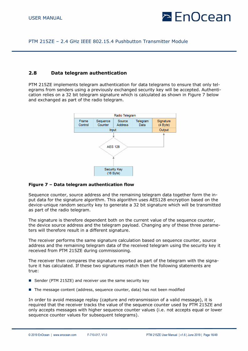
2.8 Data telegram authentication
PTM 215ZE implements telegram authentication for data telegrams to ensure that only tel-egrams from senders using a previously exchanged security key will be accepted. Authenti-cation relies on a 32 bit telegram signature which is calculated as shown in Figure 7 below and exchanged as part of the radio telegram.
Figure 7 – Data telegram authentication flow Sequence counter, source address and the remaining telegram data together form the in-put data for the signature algorithm. This algorithm uses AES128 encryption based on the device-unique random security key to generate a 32 bit signature which will be transmitted as part of the radio telegram.
The signature is therefore dependent both on the current value of the sequence counter, the device source address and the telegram payload. Changing any of these three parame-ters will therefore result in a different signature. The receiver performs the same signature calculation based on sequence counter, source address and the remaining telegram data of the received telegram using the security key it received from PTM 215ZE during commissioning. The receiver then compares the signature reported as part of the telegram with the signa-ture it has calculated. If these two signatures match then the following statements are true: Sender (PTM 215ZE) and receiver use the same security key
The message content (address, sequence counter, data) has not been modified
In order to avoid message replay (capture and retransmission of a valid message), it is required that the receiver tracks the value of the sequence counter used by PTM 215ZE and only accepts messages with higher sequence counter values (i.e. not accepts equal or lower sequence counter values for subsequent telegrams).

USER MANUAL
PTM 215ZE – 2.4 GHz IEEE 802.15.4 Pushbutton Transmitter Module
© 2019 EnOcean | www.enocean.com F-710-017, V1.0 PTM 215ZE User Manual | v1.6 | June 2019 | Page 17/49
2.8.1 Authentication implementation
PTM 215ZE implements telegram authentication according to the ZigBee Green Power spec-ification. It uses AES128 in CCM (Counter with CBC-MAC) mode as described in IETF
RFC3610. At the time of writing, the RFC3610 standard could be found here: https://www.ietf.org/rfc/rfc3610.txt The 13 Byte CCM Nonce (number used once – unique) initialization value is constructed as concatenation of 4 byte Device ID, 4 byte Device ID again, 4 byte Sequence Counter and 1 status byte of value 0x05. Note that both Device ID and Sequence Counter use little endian format (least significant byte first). Figure 8 below shows the structure of the AES128 Nonce.
Figure 8 – AES128 Nonce structure The AES128 Nonce and the 128 bit device-unique security key are then used to calculate a 32 bit signature of the authenticated telegram payload shown in Figure 9 below.
Figure 9 – Authenticated payload The calculated 32 bit signature is then appended to the data telegram payload as shown in chapter 2.7. The security key required for the telegram authentication can be obtained in two ways: Product DMC code
Each PTM 215ZE device contains a product label with a DMC code that identifies the
Source ID and the Private Security Key used by this device, see below.
Commissioning telegram The security key is transmitted as part of the commissioning telegram, see chapter 2.9.3

USER MANUAL
PTM 215ZE – 2.4 GHz IEEE 802.15.4 Pushbutton Transmitter Module
© 2019 EnOcean | www.enocean.com F-710-017, V1.0 PTM 215ZE User Manual | v1.6 | June 2019 | Page 18/49
2.9 Commissioning mode
Commissioning mode is used to commission (teach-in, learn in) PTM 215ZE into a specific receiver or network. To do so, PTM 215ZE provides two key functions:
Transmission of a commissioning telegram in order to learn-in PTM 25ZE into a network
Radio channel selection in order to set the radio channel of PTM 215ZE to that used by
the network
These functions are described subsequently in more detail.
2.9.1 Commissioning mode entry
Commissioning mode is entered using a special button contact sequence. This is illustrated in Figure 10 below.
Figure 10 – Button sequence for commissioning mode

USER MANUAL
PTM 215ZE – 2.4 GHz IEEE 802.15.4 Pushbutton Transmitter Module
© 2019 EnOcean | www.enocean.com F-710-017, V1.0 PTM 215ZE User Manual | v1.6 | June 2019 | Page 19/49
To enter commissioning mode, start by selecting one button contact of PTM 215ZE. Any contact of PTM 215ZE (A0, A1, B0, B1) can be used. This contact is referred to as ButtonX in Figure 10 above.
Next, execute the following long-short-long sequence:
1. Press and hold the selected button contact together with the energy bar for more than 7 seconds before releasing it
2. Press the selected button contact together with the energy bar quickly (hold for less than 2 seconds)
3. Press and hold the selected button contact together with the energy bar again for
more than 7 seconds before releasing it Upon detection of this sequence, PTM 215ZE will enter commissioning mode and transmit a commissioning telegram on the current radio channel.
Sometimes the user might be unsure if PTM 215ZE is operating in normal mode or in com-missioning mode and if part of the entry sequence into commissioning mode has already been executed. PTM 215ZE can always be set into a defined state (normal mode) by shortly (< 7s) pressing two different buttons one after another. After that, PTM 215ZE will operate in data mode
and the full sequence for commissioning mode entry (long-sort-long) has to be executed to enter commissioning mode.
2.9.2 Commissioning telegram transmission
PTM 215ZE will transmit a commissioning telegram on the current radio channel immedi-ately upon entering commissioning mode. This allows teach-in into additional devices with-out changing the currently used radio channel. The default radio channel used by PTM 215ZE is channel 11 (see chapter 2.5). It can be subsequently adjusted as described in the following chapter.
Whenever a new radio channel is selected, PTM 215ZE will transmit a commissioning tele-gram on the new radio channel. This enables the receiver to provide feedback to the user to indicate when PTM 215ZE has reached the correct radio channel (i.e. when the receiver receives a commissioning telegram from PTM 215ZE on the radio channel the receiver is using). See chapter 2.9.5 for a discussion of feedback mechanisms.
The format of PTM 215ZE radio telegrams including commissioning telegrams is described below.

USER MANUAL
PTM 215ZE – 2.4 GHz IEEE 802.15.4 Pushbutton Transmitter Module
© 2019 EnOcean | www.enocean.com F-710-017, V1.0 PTM 215ZE User Manual | v1.6 | June 2019 | Page 20/49
2.9.3 Commissioning telegram format
Figure 11 below shows the MAC payload structure for commissioning telegrams.
Figure 11 – MAC Payload structure for commissioning telegrams
The following fields are used for commissioning telegrams: Telegram Control (1 byte)
The Telegram Control field is set to 0x0C to identify a standard telegram (secure commu-
nication will be established based on the commissioning telegram)
Source ID (4 bytes) The Source ID field contains a 4 byte ID uniquely identifying each PTM 215ZE device
Command (1 byte) The Command field is set to 0xE0 to identify this command as commissioning command
Device Type (1 byte) The Device Type field is set to 0x02 to identify PTM 215ZE as ON / OFF switch
Device Options (2 byte)
The Device Options field is set to 0xF281 to identify the device as PTM 215ZE communi-
cating securely using the AES128 (CBC mode) algorithm and a 4 byte sequence counter to generate a 4 byte signature
Encrypted Device-unique Security Key (16 bytes)
Each PTM 215ZE contains a random, device-specific security key which is generated as part of the production flow. During commissioning, this key is transmitted in encrypted form as specified by the zigbee Green Power specification.
Security Key Validation (4 bytes)
In order to ensure correct reception, an additional 4 byte validation value is provided.
Sequence Counter (4 bytes) The Sequence Counter is an always incrementing counter which is used as part of the security processing to avoid replay attacks (sending the same telegram again). Receiving devices shall only accept data telegrams with sequence counter values higher than that of the last received telegram; therefore the current value needs to be commu-nicated during commissioning.

USER MANUAL
PTM 215ZE – 2.4 GHz IEEE 802.15.4 Pushbutton Transmitter Module
© 2019 EnOcean | www.enocean.com F-710-017, V1.0 PTM 215ZE User Manual | v1.6 | June 2019 | Page 21/49
2.9.3.1 Commissioning telegram example
Below is an example of the MAC payload of a commissioning telegram from a PTM 215ZE device:
0C FB 02 50 01 E0 02 81 F2 88 42 0A 19 66 16 6C 7A A2 15 B2 B7 72 18 BD A3 0F 32 8C 32 27 00 00 00
The three most relevant fields for commissioning are marked red in the example above: Source ID
Note that this is transmitted in little endian format, i.e. the actual Source ID is 0x015002FB
Encrypted security key
This the encrypted version of the actual security key; the encryption is implemented ac-cording to the zigbee Green Power specification
Sequence Counter Note that this is transmitted in little endian format, i.e. the actual Sequence Counter is 0x00000027
For a description how to decode the encrypted security key please refer to the zigbee Green
Power specification.

USER MANUAL
PTM 215ZE – 2.4 GHz IEEE 802.15.4 Pushbutton Transmitter Module
© 2019 EnOcean | www.enocean.com F-710-017, V1.0 PTM 215ZE User Manual | v1.6 | June 2019 | Page 22/49
2.9.4 Radio channel adjustment
The radio channel used by PTM 215ZE can be changed whenever PTM 215ZE is in commis-sioning mode. Refer to chapter 2.5 for a summary of the supported radio channels.
In order to change the radio channel, press the selected button contact shortly (< 7s) once after entry into commissioning mode. This will reset the radio channel used by PTM 215ZE to channel 11 and enable subsequent channel adjustment. If PTM 215ZE was already operating on channel 11 (default condition) then the radio chan-nel will remain unchanged. This ensures that PTM 215ZE will always use channel 11 as starting point for the radio channel adjustment. The radio channel can now be incremented by continuing to press the selected button con-tact shortly (< 7s). For each such button press, the radio channel is incremented. If chan-nel 26 has been reached then channel 11 will be used next.
2.9.4.1 Radio channel adjustment examples
Example 1: PTM 215ZE operating on channel 11 (out of the box condition) In this case, PTM 215ZE would send a commissioning telegram on channel 11 immediately after detecting the long-short-long sequence. After that, it would for each additional short button press send commissioning telegrams on incrementing radio channels starting with channel 11. This means that the channel sequence would be: 11 (current channel) - 11 – 12 – 13 … 25 – 26 – 11 – 12 and so on Example 2: PTM 215ZE operating on channel 15 In this case, PTM 215ZE would send a commissioning telegram on channel 15 immediately
after detecting the long-short-long sequence. After that, it would for each additional button press send commissioning telegrams on in-crementing radio channels starting with channel 11. This means that the channel sequence would be: 15 (current channel) - 11 – 12 – 13 … 25 – 26 – 11 – 12 and so on

USER MANUAL
PTM 215ZE – 2.4 GHz IEEE 802.15.4 Pushbutton Transmitter Module
© 2019 EnOcean | www.enocean.com F-710-017, V1.0 PTM 215ZE User Manual | v1.6 | June 2019 | Page 23/49
2.9.5 Determining the correct radio channel
The user requires system feedback to determine if the correct radio channel has been reached.
Several methods are possible for that, including: Feedback from the device into which PTM 215ZE is learned in
E.g. blinking a status light, toggling a connected load, moving a motor etc.
Feedback from a dedicated user interface This could for instance instruct the user on the required key sequence and confirm cor-rect execution
It is the responsibility of the system designer to define a suitable feedback mechanism.
2.9.6 Storing the new radio channel and return to data mode
If PTM 215ZE has been successfully set to the desired radio channel then this radio channel has to be stored and operation should return to data mode.
This is achieved by pressing any button contact other than the one used for entry into commissioning mode (and channel change). So if button contact A0 was used to enter commissioning mode then pressing button contact A1, B0 or B1 will cause storing of the current radio channel and return to data mode. Failure to store the selected radio channel and to return to normal mode could cause acci-dental reconfiguration of PTM 215ZE.

USER MANUAL
PTM 215ZE – 2.4 GHz IEEE 802.15.4 Pushbutton Transmitter Module
© 2019 EnOcean | www.enocean.com F-710-017, V1.0 PTM 215ZE User Manual | v1.6 | June 2019 | Page 24/49
3 Device Integration
PTM 215ZE is designed for integration into button or rocker based switches. It implements the established PTM 2xx mechanical form factor and can therefore be used with a wide va-
riety of existing designs.
3.1 Mechanical Interface Characteristics
Energy bow travel / operating force 1.8 mm / typ. 10 N At room temperature
Only one of the two energy bows may be actuated at the same time!
Restoring force at energy bow typ. 0.7 N Minimum restoring force of 0.5 N is required for correct operation
Number of operations at 25°C typ. 100.000 actuations tested according to VDE 0632 / EN 60669
Cover material Hostaform (POM)
Energy bow material PBT (50% GV)
3.2 Mechanical Interface Drawings
Figure 12 – PTM 215ZE, tilted view (including rocker catwalks)

USER MANUAL
PTM 215ZE – 2.4 GHz IEEE 802.15.4 Pushbutton Transmitter Module
© 2019 EnOcean | www.enocean.com F-710-017, V1.0 PTM 215ZE User Manual | v1.6 | June 2019 | Page 25/49
1) these catwalks are not needed when using one single rocker only 2) dimensions of rocker part
Figure 13 – PTM 215ZE, top view (note cut A, B and C marking)

USER MANUAL
PTM 215ZE – 2.4 GHz IEEE 802.15.4 Pushbutton Transmitter Module
© 2019 EnOcean | www.enocean.com F-710-017, V1.0 PTM 215ZE User Manual | v1.6 | June 2019 | Page 26/49
Figure 14 – PTM 215ZE, cut A
2) dimensions of rocker part Figure 15 – PTM 215ZE, cut B and C

USER MANUAL
PTM 215ZE – 2.4 GHz IEEE 802.15.4 Pushbutton Transmitter Module
© 2019 EnOcean | www.enocean.com F-710-017, V1.0 PTM 215ZE User Manual | v1.6 | June 2019 | Page 27/49
Hatched areas: support planes
Figure 16 – PTM 215ZE rear view

USER MANUAL
PTM 215ZE – 2.4 GHz IEEE 802.15.4 Pushbutton Transmitter Module
© 2019 EnOcean | www.enocean.com F-710-017, V1.0 PTM 215ZE User Manual | v1.6 | June 2019 | Page 28/49
2) dimensions of rocker part
Figure 17 – PTM 215ZE, side view
If the rocker is not mounted on the rotation axis of PTM 215ZE several tolerances have to be considered! The measure from support plane to top of the energy bow
is 7.70 mm +/- 0.3 mm!
The movement of the energy bow must not be limited by mounted rockers!
Catwalks of the switch rocker must not exert continuous forces on the button con-tacts!

USER MANUAL
PTM 215ZE – 2.4 GHz IEEE 802.15.4 Pushbutton Transmitter Module
© 2019 EnOcean | www.enocean.com F-710-017, V1.0 PTM 215ZE User Manual | v1.6 | June 2019 | Page 29/49
It is required to use non-conductive material (no metal or plastic with metal or graphite elements) for the rockers, the frame and the base plate to ensure best
transmission range.
PTM 215ZE is powered by the electromagnetic generator ECO 200. For proper function there has to be a keep out zone of 60mm for magnets or ferromagnetic materials around the center of PTM 215ZE.

USER MANUAL
PTM 215ZE – 2.4 GHz IEEE 802.15.4 Pushbutton Transmitter Module
© 2019 EnOcean | www.enocean.com F-710-017, V1.0 PTM 215ZE User Manual | v1.6 | June 2019 | Page 30/49
3.3 Device Label
Each PTM 215ZE module contains a product label identifying key parameters such as manu-facturing date, device ID and an optically readable code that can be used to automatically
scan device parameters. Previous versions (DA-02) used a custom product label described in chapter 3.3.1 while the latest version uses the EnOcean standard product label as described in chapter 3.3.2
3.3.1 DA-02 Product Label
The device label structure for the previous PTM 215ZE DA-02 product revision is shown for reference in Figure 18 below. This label version contains an optically readable Data Matrix Code (DMC, marked with a green frame) on the lower right hand side of the device label which can be used to auto-
matically scan device parameters.
Figure 18 – PTM 215ZE Device Label (Revision DA-02)
The DMC uses the ECC200 standard and can be read by a by a suitable commissioning tool (e.g. smartphone) which is already part of the network into which PTM 215ZE will be com-missioned. The commissioning tool can then send these parameters to the intended receiver of PTM 215ZE radio telegrams.

USER MANUAL
PTM 215ZE – 2.4 GHz IEEE 802.15.4 Pushbutton Transmitter Module
© 2019 EnOcean | www.enocean.com F-710-017, V1.0 PTM 215ZE User Manual | v1.6 | June 2019 | Page 31/49
3.3.1.1 Data Matrix Code (DMC) format
The commissioning DMC provided by PTM 215ZE uses the following format:
<PRODUCT_NAME>ID<SOURCE_ID>OOB<DEVICE_KEY>
This identifies the following parameters:
Product name (always “PTM215ZE”)
4 byte Source ID (unique for each device)
16 byte device-unique random security key (different for each device)
Figure 19 below shows an example of a PTM 215ZE DMC code.
Figure 19 – Example of a PTM 215ZE DMC code This specific DMC encodes the following string:
PTM215ZEID015002FBOOBD8F7048D01F7AAEEC0A757B862F96301
For better readability, the same reading is shown below coloured red, green and blue to identify the different parts: PTM215ZEID015002FBOOBD8F7048D01F7AAEEC0A757B862F96301
This particular DMC reading would identify the following parameters:
Product name = PTM215ZE
Source ID = 015002FB
Device-unique random security key = D8F7048D01F7AAEEC0A757B862F96301

USER MANUAL
PTM 215ZE – 2.4 GHz IEEE 802.15.4 Pushbutton Transmitter Module
© 2019 EnOcean | www.enocean.com F-710-017, V1.0 PTM 215ZE User Manual | v1.6 | June 2019 | Page 32/49
3.3.2 DA-03 Product Label
The latest revision DA-03 of PTM 215ZE uses the new EnOcean standard product label as shown in Figure 20 below.
The key difference to the previous format is the use of one unified (and larger) QR code instead of two separate small Data Matric Code which improves readability.
Figure 20 – PTM 215ZE device label (Revision DA-03)
3.3.2.1 QR Code format
The QR code used in the new product label encodes the product parameter according to the ANSI/MH10.8.2-2013 industry standard. The QR code shown in Figure 20 above encodes the following string: 30S01700100+Z0123456789ABCDEF0123456789ABCDEF+30PS3271-A215+2PDA03+S01432902018866
Table 3 below describes the ANSI/MH10.8.2 data identifiers used by the PTM 215B device label and shows the interpretation of the data therein.
Identifier Length of data (excluding identifier) Value
30S 8 characters Source Address (hex)
Z 32 characters Security Key (hex)
30P 10 characters Ordering Code (S3271-A215)
2P 4 characters Step Code - Revision (DA-03)
S 14 characters Serial Number
Table 3 – QR code format

USER MANUAL
PTM 215ZE – 2.4 GHz IEEE 802.15.4 Pushbutton Transmitter Module
© 2019 EnOcean | www.enocean.com F-710-017, V1.0 PTM 215ZE User Manual | v1.6 | June 2019 | Page 33/49
4 APPLICATION INFORMATION
4.1 Transmission range
The main factors that influence the system transmission range are: - Type and location of the antennas of receiver and transmitter - Type of terrain and degree of obstruction of the link path - Sources of interference affecting the receiver - “Dead spots” caused by signal reflections from nearby conductive objects.
Since the expected transmission range strongly depends on this system conditions, range tests should always be performed to determine the reliably achievable range under the giv-en conditions.
The following figures should be treated as a rough guide only:
- Line-of-sight connections Typically 15 m range in corridors, up to 50 m in halls
- Plasterboard walls / dry wood Typically 15 m range, through max. 2 walls
- Ferro concrete walls / ceilings Maximum 1 wall or ceiling, depending on thickness and material
- Fire-safety walls, elevator shafts, staircases and similar areas should be considered as shielded
The angle at which the transmitted signal hits the wall is very important. The effective wall thickness – and with it the signal attenuation – varies according to this angle. Signals
should be transmitted as directly as possible through the wall. Wall niches should be avoid-ed. Other factors restricting transmission range include:
- Switch mounting on metal surfaces (up to 30% loss of transmission range) - Hollow lightweight walls filled with insulating wool on metal foil - False ceilings with panels of metal or carbon fibre - Lead glass or glass with metal coating, steel furniture
The distance between the receiver and other transmitting devices such as computers, audio and video equipment that also emit high-frequency signals should be at least 0.5 m.

USER MANUAL
PTM 215ZE – 2.4 GHz IEEE 802.15.4 Pushbutton Transmitter Module
© 2019 EnOcean | www.enocean.com F-710-017, V1.0 PTM 215ZE User Manual | v1.6 | June 2019 | Page 34/49
5 REGULATORY INFORMATION
PTM 215ZE has been certified according to FCC (US), ISED (Canada) and RED (Europe) regulations. Changes or modifications not expressly approved by EnOcean could void the
user's authority to operate the equipment.
5.1 RED for the European Market
The Radio Equipment Directive (2014/53/EU, typically referred to as RED) replaces R&TTE directive from 1999 as regulatory framework for radio products in the European Union. All products sold to final customers after 12th of June, 2017 have to be compliant to RED. At the time of writing, the text of the RED legislation was available from this link: http://eur-lex.europa.eu/eli/dir/2014/53/oj Dolphin radio modules are components which are delivered to OEM manufacturers for their
use/integration in final or combined products. It is the responsibility of the OEM manufac-turer to demonstrate compliance to all applicable EU directives and standards. The EnOcean attestation of conformity can be used as input to the declaration of conformity for the full product. At the time of writing, guidance on the implementation of EU product rules – the so called
“Blue Guide” – was available from this link: http://ec.europa.eu/DocsRoom/documents/18027/ Specifically within the new RED framework, all OEM manufacturers have for instance to fulfill the following additional requirements:
Provide product branding (on the product) clearly identifying company name or brand and product name as well as type, charge or serial number for market surveil-lance
Include (with the product) documentation containing full postal address of the man-ufacturer as well as radio frequency band and max. transmitting power
Include (with the product) user manual, safety information and a declaration of con-
formity for the final product in local language
Provide product development and test documentation upon request
Please contact an accredited test house for detailed guidance.
USER MANUAL
PTM 215ZE – 2.4 GHz IEEE 802.15.4 Pushbutton Transmitter Module
© 2019 EnOcean | www.enocean.com F-710-017, V1.0 PTM 215ZE User Manual | v1.6 | June 2019 | Page 35/49
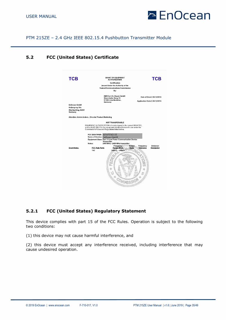
5.2 FCC (United States) Certificate
5.2.1 FCC (United States) Regulatory Statement
This device complies with part 15 of the FCC Rules. Operation is subject to the following two conditions:
(1) this device may not cause harmful interference, and (2) this device must accept any interference received, including interference that may cause undesired operation.

USER MANUAL
PTM 215ZE – 2.4 GHz IEEE 802.15.4 Pushbutton Transmitter Module
© 2019 EnOcean | www.enocean.com F-710-017, V1.0 PTM 215ZE User Manual | v1.6 | June 2019 | Page 36/49
5.3 ISED (former Industry Canada) Certificate
5.2.2 ISED (former Industry Canada) Regulatory Statement
This device complies with Industry Canada licence-exempt RSS standard(s). Operation is subject to the following two conditions: (1) this device may not cause interference, and
(2) this device must accept any interference, including interference that may cause unde-sired operation of the device. Le présent appareil est conforme aux CNR d'Industrie Canada applicables aux appareils radio exempts de licence. L'exploitation est autorisée aux deux conditions suivantes : (1) l'appareil ne doit pas produire de brouillage, et (2) l'utilisateur de l'appareil doit accepter tout brouillage radioélectrique subi, même si le brouillage est susceptible d'en compromettre le fonctionnement.”

USER MANUAL
PTM 215ZE – 2.4 GHz IEEE 802.15.4 Pushbutton Transmitter Module
© 2019 EnOcean | www.enocean.com F-710-017, V1.0 PTM 215ZE User Manual | v1.6 | June 2019 | Page 37/49
A Understanding PTM 215ZE telegram structure
This appendix describes – purely for reference purposes – how to analyse the PTM 215ZE radio telegram structure using the TI CC2531EMK packet sniffer (USB dongle) on a Win-
dows 7 based system.
A.1 Installation instructions for TI CC2531 packet sniffer
The following description assumes the use of the TI CC2531EMK described here:
http://www.ti.com/tool/cc2531emk
CC2531EMK can be used in conjunction with the “TI SmartRF Protocol Packet Sniffer” to capture and visualize IEEE 802.15.4 data telegrams.
To use TI SmartRF Protocol Packet Sniffer, please download the SW package from the TI
website. At the time of writing, the SW could be obtained using this link:
http://www.ti.com/tool/packet-sniffer
Please download and install this SW before proceeding with the instructions given in the next chapter.
A.1.1 CC2531EMK setup
After setting up the TI SmartRF Protocol Packet Sniffer please insert the CC2531EMK USB dongle into a USB port of the PC and make sure that the green LED of the dongle is active.
Please make sure that the required device driver for the CC2531EMK has been correctly
installed. To do so, please check the Device Manager where you should see an entry named “CC2531 USB Dongle” under the group label “CEBAL Controlled Devices”.
Figure 21 – Correctly installed CC2531EMK

USER MANUAL
PTM 215ZE – 2.4 GHz IEEE 802.15.4 Pushbutton Transmitter Module
© 2019 EnOcean | www.enocean.com F-710-017, V1.0 PTM 215ZE User Manual | v1.6 | June 2019 | Page 38/49
A.2 Configuration
After the installation of the CC2531EMK driver, please start the TI SmartRF Packet Sniffer
program. The protocol selection dialog program window which appears after the start of is shown in Figure 22 below.
Figure 22 – Protocol selection dialog of TI SmartRF Packet Sniffer
In this dialog, please select “IEEE 802.15.4/ZigBee” as shown above and press the “Start” button. Once the main window comes up, please make sure that “CC2531” is shown in the
“Capturing device” tab and in the “RF device:” footer line as shown in Figure 23 below.
Figure 23 – Main window TI SmartRF Packet Sniffer

USER MANUAL
PTM 215ZE – 2.4 GHz IEEE 802.15.4 Pushbutton Transmitter Module
© 2019 EnOcean | www.enocean.com F-710-017, V1.0 PTM 215ZE User Manual | v1.6 | June 2019 | Page 39/49
Out of the box, PTM 215ZE is configured for using IEEE 802.15.4 radio channel 11. Make sure that this radio channel (0x0B) is selected in the “Radio Configuration” tab and shown in the “Channel:” footer line.
Figure 24 – Radio channel selection
The data fields that will be displayed can be selected in the “Select fields” tab. Make sure that all “MAC Header”, “Data” and “Footer” fields are selected and that the “LQI/RSSI” drop-down list is set to “RSSI”.
Figure 25 – Payload selection
The TI SmartRF Packet Sniffer is now ready.

USER MANUAL
PTM 215ZE – 2.4 GHz IEEE 802.15.4 Pushbutton Transmitter Module
© 2019 EnOcean | www.enocean.com F-710-017, V1.0 PTM 215ZE User Manual | v1.6 | June 2019 | Page 40/49
A.3 Data capture
Press the triangular button ( ) to start the radio capture and press the auto-scoll button
( ) to automatically select the most recent data telegram. Then press a button of PTM 215ZE. You should now see the captured radio telegrams (PTM 215Z sends several redun-
dant radio telegrams per user action).
Figure 26 – Captured telegram data

USER MANUAL
PTM 215ZE – 2.4 GHz IEEE 802.15.4 Pushbutton Transmitter Module
© 2019 EnOcean | www.enocean.com F-710-017, V1.0 PTM 215ZE User Manual | v1.6 | June 2019 | Page 41/49
A.4 Interpretation of the telegram data
The following parameters within captured radio telegrams are typically of interest:
1. MAC Payload This will contain the ID of the sender, various control and security data fields as well as the actual command data (1 byte) The structure of this field is outlined subsequently in more detail.
2. RSSI
This will show the received signal strength
3. FCS This will show the frame integrity (OK / not OK) and should normally show “OK”.
A.4.1 MAC Payload
Below is an example of a captured MAC payload:
The hexadecimal representation of this specific payload is:
8C 30 FB 02 50 01 25 00 00 00 23 AA 99 E8 76
The location and interpretation of key parameters is described in the following chapters.
A.4.2 Device ID
The device ID is used to uniquely identify each device in the network. It is 4 byte long and is allocated to byte 2…5 of the MAC payload as highlighted below:
8C 30 FB 02 50 01 25 00 00 00 23 AA 99 E8 76
Note that the byte order is little endian, therefore the ID of this specific device is 0x015002FB.
A.4.3 Sequence Counter
The sequence counter is used to uniquely identify each telegram in order to avoid telegram replay. It is 4 byte long and is allocated to byte 6…9 of the MAC payload as highlighted be-low:
8C 30 FB 02 50 01 25 00 00 00 23 AA 99 E8 76
Note that the byte order is little endian, therefore the current sequence counter value of this specific device is 0x00000025.

USER MANUAL
PTM 215ZE – 2.4 GHz IEEE 802.15.4 Pushbutton Transmitter Module
© 2019 EnOcean | www.enocean.com F-710-017, V1.0 PTM 215ZE User Manual | v1.6 | June 2019 | Page 42/49
A.4.4 Command payload
The command payload identifies the action performed on the switch (i.e. which buttons have been pressed). The command is allocated to byte 10 of the MAC payload as highlight-ed below:
8C 30 FB 02 50 01 25 00 00 00 23 AA 99 E8 76
In this case it is 0x23 meaning that button A0 has been released. Refer to chapter 2.7.1 for the description of commands supported by PTM 215ZE.
A.4.5 Telegram Signature
The PTM 215ZE radio telegram is authenticated via a 32 Bit signature. This signature is calculated based on the private key (unique for each device), the data payload and a 32 Bit sequence counter (which is incremented for each data telegram).
This approach prevents unauthorized senders from sending commands. Note that the con-
tent of the telegram itself is not encrypted, i.e. the switch command is sent as plain text.
The telegram signature is transmitted using the last 4 byte of the telegram:
8C 30 FB 02 50 01 25 00 00 00 23 AA 99 E8 76
Note that the signature changes with each transmission even if the remainder of the MAC payload remains the same.
This is due to the inclusion of the rolling code into the MIC calculation which prevents mes-sage replay attacks (capture and reuse of a previous message).

USER MANUAL
PTM 215ZE – 2.4 GHz IEEE 802.15.4 Pushbutton Transmitter Module
© 2019 EnOcean | www.enocean.com F-710-017, V1.0 PTM 215ZE User Manual | v1.6 | June 2019 | Page 43/49
B Authentication of PTM 215ZE data telegrams
PTM 215ZE provides the option to authenticate its data telegrams as described in chapter 2.8. The authentication mechanism used by PTM 215ZE is standardized as RFC3610 and
specified within the zigbee Green Power specification. The full RFC3610 specification could be found here at the time of writing and should be used as primary source of information: https://www.ietf.org/rfc/rfc3610.txt The following description aims to summarize the security processing steps for users not deeply familiar with cryptography in general or RFC3610 and zigbee Green Power in par-
ticular.
B.1 Algorithm input parameters
The purpose of the security processing in PTM 215ZE is to calculate a unique signature that can be used to verify authenticity (telegram has not been modified) and originality (tele-
gram comes from the assumed sender) of a telegram. To do so, two types of algorithm parameters are required:
Constant algorithm input parameters These parameters identify high level algorithm and telegram properties and are the same for any PTM 215ZE telegram
Variable algorithm input parameters
These parameters identify telegram-specific parameters and therefore depend on the specifics of the transmitted telegram
B.1.1 Constant input parameters
The RFC3610 implementation in PTM 215ZE requires two constant input parameters:
Length field size This is the size (in byte) of the field used to encode the length of the input data (which is the payload to be authenticated). The size of PTM 215ZE payload to be au-thenticated is 11 byte; therefore one byte would be easily sufficient to encode the payload size. The minimum value permitted by the standard is however 2 bytes
which is therefore chosen.
Signature size This is the desired size of the generated signature which is 4 byte for PTM 215ZE
Table 4 below summarizes these constant algorithm parameters.
Parameter Comment / Description Example
Length Field Size
Size (in bytes) of the field used to encode the input length
2 (always, minimum permissible size)
Signature Size
Desired size (in byte) of the signa-ture generated by the algorithm
4 (always)
Table 4 – Constant algorithm input parameters

USER MANUAL
PTM 215ZE – 2.4 GHz IEEE 802.15.4 Pushbutton Transmitter Module
© 2019 EnOcean | www.enocean.com F-710-017, V1.0 PTM 215ZE User Manual | v1.6 | June 2019 | Page 44/49
B.1.2 Variable input parameters
The RFC3610 implementation in PTM 215ZE requires four variable input parameters:
Source address The 4 byte source address used to identify the sender of an authenticated message. The source address is required in little endian (least significant byte first) format.
Input data (Payload to be authenticated) The authenticated payload contains source address, sequence counter, switch status and optional data (if present). See chapter 2.8.1 for a description of the authenti-
cated payload.
Input length (Size of the payload to be authenticated) The length of the payload to be authenticated is always 11 byte a described in chap-ter 2.8.1.
Sequence counter Each PTM 215ZE contains a sequence counter which is initialized to zero during pro-duction and increased for each telegram that is sent. The sequence counter is transmitted as part of the input data. The receiver of PTM 215ZE telegrams keeps track of this counter and will accept on-ly telegrams with counter values higher than the highest previously used value. This eliminates the possibility of reusing previously transmitted telegrams. Note that the individual (identical) advertising telegrams used to encode the same data telegram use the same sequence counter value.
Private key Each PTM 215ZE is programmed with a random 16 byte security key during manu-facturing.
Table 5 below summarizes these parameters.
Parameter Comment / Description Example
Source Address
Unique source address of the PTM 215ZE module (little endian)
FB025001 (little endian representa-tion of 015002FB)
Input Data Telegram data to be authenticated 8C30FB0250012500000023
Length of Input Data
Length of input data in bytes, encod-ed using 2 bytes
0x000B (11 bytes)
Sequence Counter
Incrementing counter to avoid replay Part of the input data
25000000 (little endian representa-tion of the counter value 00000025)
Private Key 128 bit random key that is known both to sender and receiver
D8F7048D01F7AAEEC0A757B862F96301
Table 5 – Variable input parameters

USER MANUAL
PTM 215ZE – 2.4 GHz IEEE 802.15.4 Pushbutton Transmitter Module
© 2019 EnOcean | www.enocean.com F-710-017, V1.0 PTM 215ZE User Manual | v1.6 | June 2019 | Page 45/49
B.1.3 Obtaining the private key
All required parameters except the private key can be directly extracted from the received message that shall be authenticated.
The private key – the common secret shared between sender and receiver – has to be ob-tained via specific mechanisms. There are two different ways to obtain the security key of a PTM 215ZE module:
Obtaining the private key via the product DMC code
Obtaining the private key via a dedicated commissioning telegram Each option is described now in detail.
B.1.3.1 Obtaining the private key via the product DMC code
Each PTM 215ZE module contains a DMC code on its product label which identifies source address and private key of the module, The DMC code of the device used for this tutorial is shown in Figure 27 below.
Figure 27 – Example DMC code This DMC code can be read using a suitable DMC code reader (e.g. QRbot smartphones). The content of this example DMC code is:
PTM215ZEID015002FBOOBD8F7048D01F7AAEEC0A757B862F96301
The structure of the DMC code is described in chapter 3.3.1.1. The location of the security key in above DMC string is marked red for reference. This means that the private key of this device is:
D8F7048D01F7AAEEC0A757B862F96301
B.1.3.2 Obtaining the private key via a commissioning telegram
PTM 215ZE modules can send dedicated commissioning telegrams that identify their private key. Transmission of such commissioning telegrams can be triggered by means of a specific button sequence as described in chapter 2.9. The format of the commissioning telegram is described in chapter 2.9.3

USER MANUAL
PTM 215ZE – 2.4 GHz IEEE 802.15.4 Pushbutton Transmitter Module
© 2019 EnOcean | www.enocean.com F-710-017, V1.0 PTM 215ZE User Manual | v1.6 | June 2019 | Page 46/49
B.2 Internal parameters
The RFC3610 implementation in PTM 215ZE derives a set of internal parameters for further processing from the provided input parameters.
Again, there are two types of internal parameters:
Constant internal parameters These parameters are based on the high level algorithm and telegram properties and are the same for any PTM 215ZE telegram
Variable input parameters These parameters are based on the telegram-specific parameters and therefore de-pend on the specifics of the transmitted telegram
B.3 Constant internal parameters
The RFC3610 implementation in PTM 215ZE derives two internal parameters – M’ and L’ – based on the input data and uses them to construct A0_Flag and B_0_Flag which are re-quired for subsequent processing. The value of these internal parameters - listed in Table 6 below - is the same for all PTM 215ZE data telegrams.
Parameter Comment / Description Example
M’ Binary encoded output length M’ = (Output length / 2) - 1
0b001 (always)
L’ Binary encoded length field size L’ = length field size - 1
0b001 (always)
A0_Flag L’ 0x01 (always)
B0_Flag (0b01<<6) + (M’<<3) + L’ 0x49 (always)
Table 6 – Constant internal parameters

USER MANUAL
PTM 215ZE – 2.4 GHz IEEE 802.15.4 Pushbutton Transmitter Module
© 2019 EnOcean | www.enocean.com F-710-017, V1.0 PTM 215ZE User Manual | v1.6 | June 2019 | Page 47/49
B.4 Variable internal parameters
The RFC3610 implementation in PTM 215ZE derives four internal parameters – Nonce, A0, B0 and B1 – based on the telegram specific input data and the constant internal parame-
ters.
B.4.1 Forming the Nonce
The Nonce is a 13 byte initialization vector which is formed based on the concatenation of the following items:
Source address Source address (again) Sequence counter 0x05
Note that source address and sequence counter have to be in little endian format, see chapter 2.8.1.
In this example, the source address is 015002FB and the sequence counter is 00000025. The Nonce therefore is FB025001FB0250012500000005
B.4.2 Calculating the flags
The calculation uses 3 flags together with the security key:
A0_Flag is formed as concatenation of A0_Flag, Nonce and 0x0000. In this
example, A0_Flag would be 01FB025001FB02500125000000050000
B0_Flag is formed as concatenation of B0_Flag, Nonce and 0x0000. In this
example, B0_Flag would be 49FB025001FB02500125000000050000 B1_Flag is formed as concatenation of two byte data length (always 0x000B)
followed by the 11 byte of input data to be authenticated (8C30FB0250012500000023 in this example) followed by 0x000000. In this ex-
ample, B0_Flag would be 000B8C30FB0250012500000023000000
Table 7 below summarizes the internal parameters.
Parameter Comment / Description Example
Nonce 13 byte initialization vector based on concatenation of source address, sequence counter and padding, see 2.8.1
FB025001FB0250012500000005
A0 A0_Flag followed by Nonce followed by 2
byte 0x00 01FB025001FB02500125000000050000
B0 B0_Flag followed by Nonce followed by 2
byte 0x00 (no message to encode) 49FB025001FB02500125000000050000
B1
Input Length followed by Input Data fol-
lowed by 5 / 4 / 3 / 1 byte of 0x00 padding
(for optional data size = 0 / 1 / 2 / 4 byte)
000B8C30FB0250012500000023000000
Private Key 16 byte device-unique random key D8F7048D01F7AAEEC0A757B862F96301

USER MANUAL
PTM 215ZE – 2.4 GHz IEEE 802.15.4 Pushbutton Transmitter Module
© 2019 EnOcean | www.enocean.com F-710-017, V1.0 PTM 215ZE User Manual | v1.6 | June 2019 | Page 48/49
Table 7 – Variable internal parameters
B.5 Algorithm execution sequence
The algorithm uses the internal parameters A_0, B_0, B_1 together with the Private Key to
generate the authentication vector T_0 using three AES-128 and two XOR operations. The
algorithm execution sequence is shown in Figure 28 below.
Figure 28 – Authentication algorithm sequence The first four bytes of T_0 are then used to authenticate PTM 215ZE telegrams by compar-
ing them with the transmitted telegram signature (sender signature) which is transmitted as part of the data telegram. The data telegram received in this example was 8C30FB0250012500000023AA99E876. The
sender signature is specified by the last four bytes and therefore would be AA99E876 in this
example. We now calculate the receiver signature based on the received telegram payload and the private key according to the flow shown in Figure 28 above.
At the time of writing, a suitable online AES calculator could be found here: http://testprotect.com/appendix/AEScalc Likewise, a suitable XOR calculator could be found here: http://xor.pw/?

USER MANUAL
PTM 215ZE – 2.4 GHz IEEE 802.15.4 Pushbutton Transmitter Module
© 2019 EnOcean | www.enocean.com F-710-017, V1.0 PTM 215ZE User Manual | v1.6 | June 2019 | Page 49/49
X_1 = AES128(B0, Key) X_1 = AES128(49fb025001fb02500125000000050000, d8f7048d01f7aaeec0a757b862f96301) X_1 = 58bca6770cd92f723387693dcce53456 X_1A = XOR(X_1, B_1) X_1A = XOR(58bca6770cd92f723387693dcce53456, 000b8c30fb0250012500000023000000) X_1A = 58b72a47f7db7f731687693defe53456 X_2 = AES128(X1A, Key) X_2 = AES128(58b72a47f7db7f731687693defe53456, d8f7048d01f7aaeec0a757b862f96301) X_2 = a0631db5e8d9d267a61fc4f48551d608 S_0 = AES128(A0, Key) S_0 = AES128(01fb025001fb02500125000000050000, d8f7048d01f7aaeec0a757b862f96301) S_0 = 0afaf5c3ee1cedf0a3fdee22718102b0 T_0 = XOR(X_2, S_0) T_0 = XOR(a0631db5e8d9d267a61fc4f48551d608, 0afaf5c3ee1cedf0a3fdee22718102b0) T_0 = aa99e87606c53f9705e22ad6f4d0d4b8 The calculated receiver signature is formed by the first four bytes of T_0, i.e. it is AA99E876.
The receiver signature therefore matches the sender signature that was transmitted as part of the payload. This proves that the telegram originates from a sender that possesses the same private key and the telegram content has not been modified.