pt20-ec pt20-ecrr pt25-ec pt25-ecrr manual
TRANSCRIPT

PT20-EC PT20-ECRR
PT25-EC PT25-ECRR
Operators Manual
Power Technology Southeast, Inc. 634 State Road #44 Leesburg, FL 34748-8103 ♦ (352) 365-2777 ♦ Fax (352) 787-5545 ♦
4/2008 MANPT20EC

FORWARD You are now the proud owner of a Power Technology Generator powered by a Kubota engine.
This engine is a product of Kubota’s quality engineering and manufacturing. The engine is made with fine materials and manufactured under the strictest quality control standards and will assure you long satisfactory service. To obtain the best use of your engine, please read this manual carefully. It will help you become familiar with the operation of the engine and contains many helpful hints regarding engine maintenance. Continuing improvements and advancements in product design may have caused changes to your engine, which are not included in this manual.
Please contact Power Technology’s Customer Service Department for latest information on your Kubota engine or for the number of your local Kubota dealer.
TO OUR CUSTOMERS
Thank you for your purchase of a Power Technology Generator. The information contained in this
manual applies to PT20-EC, PT20-ECRR, PT25-EC, and PT25-ECRR generators. In the event you experience a problem with your generator please contact the sales dealer, one of our authorized service centers or Power Technology’s Customer Service Department directly at 1-800-760-0027 from 8:00 a.m. to 5:00 p.m. EST. Please have the generator model and serial numbers available when you call. This will help expedite service and parts to you. Parts may be obtained directly through Power Technology and shipped the same day if ordered by 3:00 p.m. EST. If required, a Major Service Manual may be ordered through Power Technology’s Customer Service Department.
Generator Model Number____________________________________________ Generator Serial Number_____________________________________________
POWER TECHNOLOGY SOUTHEAST, INC. 634 STATE RD. 44
LEESBURG, FL. 34748-8103 (352) 365-2777
FAX (352) 787-5545 www.PowerTech-Gen.com

TABLE of CONTENTS
SECTION 1: “SAFETY”
SAFE OPERATION 1-4 SECTION 2: “ENGINE”
PRE-OPERATION CHECK 1 OPERATING THE ENGINE 2-12 ENGINE SPECIFICATIONS 13 ENGINE MAINTENANCE SERVICE SCHEDULE 14 ENGINE OIL MAINTENANCE 15 ENGINE COOLANT MAINTENANCE 16 OPERATING HOURS AND SERVICE LOG 17 SECTION 3: “GENERATOR END”
“MAGNAPLUS” SERIES EXCITER TYPE GENERATOR ___________ _ 1-20 GENERATOR EXPLODED VIEW and PARTS NUMBERS_________________ 21
MARATHON SE350 VOLTAGE REGULATOR___________________________ 22-24 WIRING SCHEMATICS and RESISTANCE CHARTS______________________ 25 SECTION 4: “INSTALLATION”
SAFETY PRECAUTIONS 1-2 GENERATOR INSTALLATION in RECREATIONAL VEHICLES 3-9 SYSTEMS CONNECTION 10-13 ELECTRICAL CONNECTIONS 14-19

SECTION 1 “SAFETY”
SAFE OPERATION 1-4 Observe Safety Instructions Wear Safety Clothing Check Before Operating the Engine Keep Area Around the Engine Clean Safe Handling of Fuel and Lubricants Exhaust Gases and Fire Prevention Escaping Fluids Cautions Against Burns and Battery Explosion Keep Hands and Body Away From Rotating Parts Anti-Freeze and Disposal of Fluids Conducting Safety Checks and Maintenance This symbol, the industry’s “Safety Alert Symbol”, is used throughout this manual and on labels attached the machine itself. It warns of the potential for personal injury. It is essential that you carefully read the instructions and safety regulations before you attempt to assemble or use this unit.
WARNING: Indicates a potentially hazardous situation, which may possibly result in serious injury or possible death.
CAUTION: Indicates a potentially hazardous situation, which may possibly result in minor injury. IMPORTANT: Indicates that equipment or property damage may result
if instructions are not followed.
NOTE: Indicates helpful information.

SAFE OPERATION
Cautious operation is your best insurance against an accident. Read and understand this section carefully before operating the engine. All operators, no matter how knowledgeable they may be, should read this and other related manuals before operating the engine or any equipment attached to it. It is the owner’s responsibility to instruct all operators in safe operation. Be sure to observe the following for safe operation. OBSERVE SAFETY INSTRUCTIONS • Read, understand and follow this “OPERATORS MANUAL”
and “LABELS ON THE ENGINE” before starting and operating the engine.
• Learn how to operate and work safely. Know your equipment and its limitations. Always keep the engine in good condition. • Before allowing other people to use your engine, explain how to operate and have them read this manual before operation. • DO NOT modify the engine. UNAUTHORIZED
MODIFICATIONS to the engine may impair the function and/or safety and affect engine life.
WEAR SAFETY CLOTHING • DO NOT wear loose, torn or bulky clothing around machinery. Entanglement in rotating parts, controls or projections may cause personal injury. • Use additional safety items, e.g. hardhat, eye protection, gloves, etc., as appropriate or required. • DO NOT operate machinery or equipment while under the influence of alcohol, medication, or other drugs, or while fatigued. • DO NOT wear radio or music headphones while operating engine. CHECK BEFORE OPERATING THE ENGINE • If the engine is malfunctioning DO NOT operate until repairs are made. • Be sure all guards and shields are in place before operating the engine. Replace any that are damaged or missing. • Check to see that the area around the engine is clear of foreign objects before starting. • Always keep the engine at least 3 feet (1 meter) away from buildings or other facilities. • DO NOT allow children or livestock to approach the machine while in operation. • DO NOT start the engine by shorting across starter terminals.
1

KEEP AREA AROUND THE ENGINE CLEAN • Be sure to stop the engine before cleaning. • Keep the engine clean and free of accumulated dirt, grease and trash. • DO NOT stop the engine without idling; Temperatures around the engine rises suddenly. Keep the engine idling for about 5 minutes before stopping.
SAFE HANDLING OF FUEL AND LUBRICANTS • Always stop the engine before refueling or lubricating. • DO NOT smoke or allow flames or sparks in your working area. Fuel is extremely flammable and explosive. Never store flammable liquids in the engine compartment. • Refuel at a well-ventilated and open place. If fuel or lubricants spill, clean up immediately and properly dispose of. • DO NOT mix gasoline or alcohol with diesel fuel. The mixture can cause a fire. EXHAUST GASES AND FIRE PREVENTION • Engine exhaust fumes can be very harmful if allowed to accumulate. Be sure to run the engine in a well-ventilated area where there are no people or livestock near by. • The exhaust gas from the muffler is very hot. To prevent a fire, do not expose dry grass, oil or any other combustible materials to exhaust gas. Keep the engine and mufflers clean all the time. • To avoid a fire, be alert for leaks of flammables from hoses and lines. Be sure to check for leaks from hoses and pipes, such as fuel and hydraulic by following the maintenance check list. • To avoid a fire, do not short across power cables and wires. Check to see that all power cables and wires are in good condition. Keep all power connections clean. Bare wire or frayed insulation can cause a dangerous electrical shock and personal injury.
2
CALIFORNIA Proposition 65 Warning
Diesel Engine Exhaust and some
of it’s constituents are known by the State of California
to cause Cancer, Birth Defects and Other
Reproductive harm.

ESCAPING FLUIDS • Relieve all pressure in the air, oil and cooling systems before any lines, fittings or related items are removed or disconnected. • Be alert for possible pressure release when disconnecting any device from a system that is pressurized. DO NOT check for pressure leaks with your hands. High-pressure oil or fuel can cause personal injury. • Escaping hydraulic fluid under pressure has sufficient force to penetrate skin causing serious personal injury. • Fluid escaping from pinholes may be invisible. Use a piece of cardboard or wood to search for suspected leaks: do not use hands and body. Use safety goggles or other eye protection when checking for leaks. • If injured by escaping fluid, see a medical doctor immediately. This fluid can produce gangrene or severe allergic reaction.
CAUTIONS AGAINST BURNS AND BATTERY EXPLOSION • To avoid burns, be alert for hot components during operation and just after the engine has been shut off. Such as the muffler, muffler cover, radiator, piping, engine body, coolants, engine oil, etc. • DO NOT remove the radiator cap while the engine is running or immediately after stopping. Wait approximately ten minutes for the radiator to cool before removing the cap. • Be sure the radiator drain valve / petcock and hose clamps are tighten. Check radiator pressure cap and oil fill cap before operating the engine. • The battery presents an explosive hazard. When the battery is being activated, hydrogen and oxygen gases are extremely explosive. • Keep sparks and open flames away from the battery, especially during charging. DO NOT strike a match near the battery. • DO NOT check a batteries charge by placing a metal object across the terminals. Use a voltmeter or hydrometer. • DO NOT charge a battery if frozen, it may possibly explode. Frozen batteries must be warm up to at least 61°F (16°C) before charging. KEEP HANDS AND BODY AWAY FROM ROTATING PARTS • Keep your hands and body away from all rotating parts, such as cooling fan, v-belts, pulleys and flywheel. Contact with these rotating parts can cause serious personal injury. • Be sure to stop the engine before adjusting belt tension or checking the cooling fan. • DO NOT run the engine without safety guards installed. Be sure the safety guards are properly aligned and securely fastened before operating the engine.
3
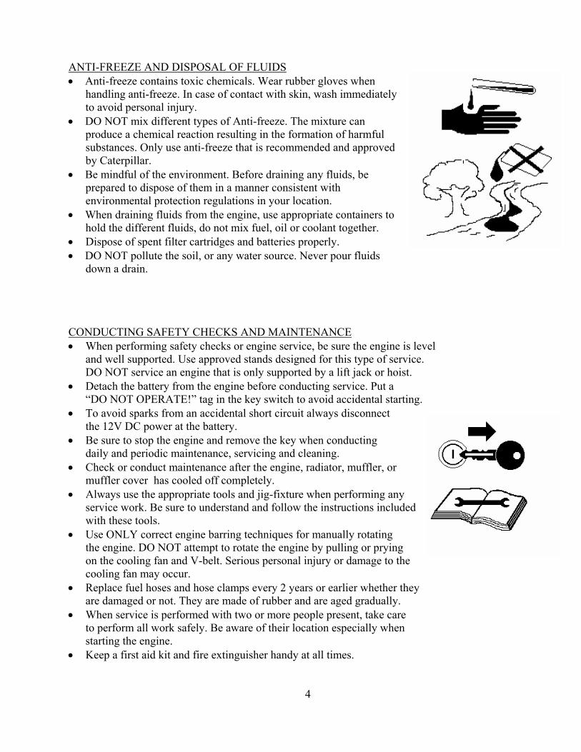
ANTI-FREEZE AND DISPOSAL OF FLUIDS • Anti-freeze contains toxic chemicals. Wear rubber gloves when handling anti-freeze. In case of contact with skin, wash immediately to avoid personal injury. • DO NOT mix different types of Anti-freeze. The mixture can produce a chemical reaction resulting in the formation of harmful substances. Only use anti-freeze that is recommended and approved by Caterpillar. • Be mindful of the environment. Before draining any fluids, be prepared to dispose of them in a manner consistent with environmental protection regulations in your location. • When draining fluids from the engine, use appropriate containers to hold the different fluids, do not mix fuel, oil or coolant together. • Dispose of spent filter cartridges and batteries properly. • DO NOT pollute the soil, or any water source. Never pour fluids down a drain. CONDUCTING SAFETY CHECKS AND MAINTENANCE • When performing safety checks or engine service, be sure the engine is level and well supported. Use approved stands designed for this type of service.
DO NOT service an engine that is only supported by a lift jack or hoist. • Detach the battery from the engine before conducting service. Put a
“DO NOT OPERATE!” tag in the key switch to avoid accidental starting. • To avoid sparks from an accidental short circuit always disconnect
the 12V DC power at the battery. • Be sure to stop the engine and remove the key when conducting
daily and periodic maintenance, servicing and cleaning. • Check or conduct maintenance after the engine, radiator, muffler, or
muffler cover has cooled off completely. • Always use the appropriate tools and jig-fixture when performing any service work. Be sure to understand and follow the instructions included with these tools. • Use ONLY correct engine barring techniques for manually rotating
the engine. DO NOT attempt to rotate the engine by pulling or prying on the cooling fan and V-belt. Serious personal injury or damage to the cooling fan may occur.
• Replace fuel hoses and hose clamps every 2 years or earlier whether they are damaged or not. They are made of rubber and are aged gradually. • When service is performed with two or more people present, take care to perform all work safely. Be aware of their location especially when starting the engine. • Keep a first aid kit and fire extinguisher handy at all times.
4

SECTION 2 “ENGINE”
PRE-OPERATION CHECK 1 Engine Break-in Period Daily Check OPERATING THE ENGINE 2-12 Power Control Module Feature Summary Operating Behavior Automatic Generator Start (AGS) Safety Monitoring and Shutdown LED Sequences Troubleshooting Guides 12V DC Power Control Module Wiring Schematic ENGINE SPECIFICATIONS 13 Kubota Model V2203-M and V2003-M-T Service Parts ENGINE MAINTENANCE SERVICE SCHEDULE 14 ENGINE OIL MAINTENANCE 15 Checking Engine Oil Level Lubricating Oil Specifications Engine Refill Capacities Lubricating Oil Viscosity Recommendations ENGINE COOLANT MAINTENANCE 16 Coolant Recommendations Ethylene Glycol / Propylene Glycol Checking Radiator Coolant Level Coolant Service Life Checking Reservoir Tank Coolant Level Cleaning Radiator Core OPERATING HOURS AND SERVICE LOG 17

PRE-OPERATION CHECK ENGINE BREAK-IN PERIOD During the engine break-in period, observe the following recommendations: 1. Change the engine oil and oil filter cartridge after the first 50 hours of operation.
(See “ENGINE OIL” in ENGINE MAINTENANCE SERVICE SCHEDULE).
2. In ambient temperature above 32°F (0°C) approximately 3-5 minutes without a load is sufficient for engine warm up. Allow additional warm up time when temperatures are below 32°F (0°C)
before placing an operating load on the engine. DAILY CHECK To prevent future engine problems from occurring, it is important to know and keep track of the engines condition. Below are items to be Inspected and Checked on a daily basis.
CAUTION: To avoid personal injury:
• Be sure all safety shields and guards are attached to the engine when operating. • To prevent a fire hazard, keep foreign materials, fuel and oil away from the battery, wiring, muffler
and engine. Check and clear them daily. Be aware of the muffler and exhaust gas heat underneath the engine compartment, this heat may ignite grass or other flammable materials.
• Follow all safety precautions as outlined in the “SAFE OPERATION” section.
1. For accurate readings the engine should be on level ground when checking engine fluids. 2. Check fluids before starting the engine. (Cold Engine)
• Lubrication System: Check Engine oil level Check for Engine oil leaks
• Cooling System: Check coolant level and condition Check for coolant leaks Check for proper installation of the radiator cap
• Fuel System: Check for sufficient quantity of fuel Check for fuel leaks
3. Check engine after starting. (Warm Engine)
• Proper Operation: Check for easy engine start
Check for fluid leaks Check for abnormal engine noises
Check for abnormal exhaust gas
1

Power Controller Module (PCM)
And Display (PCMD)

Feature Summary The PowerTech PCM controls all of the start and run processes and characteristics of any PowerTech generator. The features of the application are: Internal Ambient Temperature Sensor Provides an on-board temperature sensor. Oil Pressure Sensor / Switch Input Allows input from an external oil pressure sensor or switch. Will shut down the generator if sufficient pressure is not detected after a start-up period. Coolant Sensor / Switch Input Allows input from an external coolant temperature sensor or switch. Will shut down the generator if extreme temperature is detected. Auxiliary (Generic) Shutdown Switch Input Allows input from any external active low (ground) switch. An active state of this switch will shut down the generator immediately. DC Power Supply Voltage Measurement Measures the voltage level of the DC power supply. The DC voltage is monitored for a minimum and will shutdown the Generator if it falls below a threshold (configuration parameter). This is also reported on the PCM. AC Output Voltage Measurement Measures the voltage level of the AC output. This information is monitored to detect limit conditions. It also is reported on the PCM. Over and Under Voltage conditions are reported. AC Output Current Measurement Measures the current level of the AC output. The data is reported on the PCM and is used for current, wattage, and load measurement. AC Output Frequency Measurement Measures the frequency level of the AC output. This info is monitored to detect a valid start as well as limit conditions. It also is reported on the PCM. Over and Under Frequency conditions are reported. Warm Start Adjusts the Pre-Heat glow plug activation time according to the coolant temperature. One-Touch Remote Start Trigger In addition to control via PCM, the unit will respond to an active high digital input. The unit can be configured to either start or stop in response to activation of a momentary switch or a toggle switch. Blink Code Fault Reporting Simple diagnostic data is available through blink codes on a dedicated active high output. The PCM state as well as fault codes are displayed. Event Recording A portion of non-volatile memory is dedicated to recording diagnostic and other events. If a clock is available on the network, the time and date of the event is included. Events include diagnostic messages, starts, stops, and configuration changes. Total event capacity is roughly 2,000 events. Load Profiling The unit records the total amount of time the generator spends in each of several load intervals. The information is recorded each time the generator stops, showing the usage profile for that specific cycle. AGS Automatic Generator Starting for low battery voltage. Programmable at the factory voltage threshold and run time. Unit can sense genset battery voltage or any other battery voltage as required. Enabled or disabled by an external switch. Ignition Sensing Will shutdown genset or prevents genset from starting if DC voltage is applied from any external source. (Example: vehicle ignition, shore power sensor, or transfer switch, etc…)
2

Operating Behavior Starting The generator starts in response to the “START” button being depressed for 1 second. The PCM goes into the Pre-Heat State, followed by the Cranking State, then finally, the Running State. The PCM attempts to start the generator a specific number of times (configuration parameter) before declaring a Fault. The shutdown inputs are checked before the start is attempted. If any of these inputs are active, the start process is aborted. See the following sections for more detailed information about each state. Stopping The generator stops in response to the “START” button being depressed for 1 second. All relays are returned to their reset condition (OFF). Inputs to the PCM are not actively monitored, except the Start/Stop Button. The LED is turned off. The PCM enters the Idle State. Power Cycle/Reset If the power to the PCM is cycled, it will immediately shut down all relay outputs, stopping the generator. The unit will start with all fault and status flags reset. There may be a pause of several seconds before all the configuration information is processed and the unit is ready to accept input. Idle State The Idle State is the initial state of the PCM after a Power Cycle/Reset. The PCM returns to this state after a Stop Command. The LED is not lit. Pre-Heat State The Pre-Heat State is necessary to energize the Glow Plugs for the Cranking State. The Fuel Pump is active. The duration of this state is determined by using the coolant temperature according to the formula: < 23 ºF cranking time = 15 seconds 23 ºF – 50 ºF cranking time = 8 seconds > 50 ºF cranking time = 5 seconds The LED blinks. Cranking State The Cranking State attempts to start the generator combustion. The starter and fuel pump are active. Successful sustaining combustion is determined by measuring the AC Line 1 output frequency. The LED blinks. Running State After an initial “ignore” time (configuration parameter), inputs are monitored for out-of-bounds limits and, if needed, a shutdown command is issued. The LED is lit. Fault State The Fault State is entered if an input reaches an out-of-bounds limit. The generator is immediately stopped. A Power Cycle/Reset is required to exit the Fault state. The LED blinks the Fault Code(s) (see next section).
3

Automatic Generator Start (AGS) The Automatic Generator Start (AGS) allows the generator to start based upon the battery level. The trigger voltage is configurable via a configuration parameter. The entire feature can be enabled/disabled by a configuration parameter. The AGS feature is currently disabled, by default.
Safety Monitoring And Shutdown The PCM monitors inputs for safety limitations which might damage the generator. If any input is outside of the safe operating range, the generator is immediately shutdown and the PCM enters the FAULT state. The PCM remains in the FAULT state until a power cycle or reset occurs. The shutdown reason is displayed by blinking the LED. The thresholds used in determining faults are set by configuration parameters. These inputs are only monitored when the generator is in the RUNNING state. Before starting the generator, the following inputs are checked to see whether a start should be attempted: High Coolant Temperature, Auxiliary switch, Ignition Sense, DC Voltage and High Ambient Temperatures. These inputs are averaged over 0.6 seconds to help eliminate noise and settling issues. This averaging helps to eliminate falsely signaled shutdowns. Shutdown Reasons
Fault Reason Fault Code Description
Failure to Start 1 The generator was not able to start.
High Coolant Temperature
2 The generator coolant temperature has reached a high threshold.
Low Oil Pressure 3 The generator oil pressure has reached a critically low pressure.
High Ambient (Air) Temperature
4 The PCM measures an ambient air temperature above a specific threshold. NOTE: Temperature inside the Control Box.
AC Fault 5 A Fault with the AC was detected.
DC Fault 6 A Fault with the DC (Battery) was detected.
Auxiliary Input Active 7 The Auxiliary input is active.
Sensor Malfunction 8 One of the sensors has malfunctioned..
Ignition Sense 9 Ignition Sense is active.
The fault codes are displayed on the LED by blinking a number of times equal to the fault code, then going dark for two seconds. Multiple fault codes are displayed in the order that they have occurred. This cycle repeats until the fault is cleared by a power cycle, reset or via RV-C.
LED Sequences The LED on the Start Button is used to communicate the state of the generator in addition to any fault conditions. The PCM states are different from the Fault Codes in that the states are displayed continuously (i.e. no two second pause). PCM State
PCM State LED Notes
Idle State off
Pre-Heat Blink (25% duty cycle)
Cranking State Blink (50% duty cycle)
Running State on
Fault State <various> See “Shutdown Reasons” Section
4

CODE 2 or 8
Replace Defective Parts as Needed
Check Wiring From Sensor to
Terminal 13 on PCM
If “OK” Check Sensor
5
CODE 1 or 6
ENGINE TROUBLE SHOOTING
ENGINE STARTS BUT WON’T RUN
Check Flash Code Indicator at
PCMD
Engine High Water Temp.
Fill System With 50/50 Mix
Check Coolant Level/Condition
Check Radiator Air Flow / Belts
Clean Core Tighten / Replace
Belts
Failure To Start
Check Fuel Filter/Supply
Check Battery Voltage
Check Circuit To Actuator
If “OK” Check Fuel System
If “OK” Replace Actuator
Bleed Air From System
Check Fuel Pump / Circuit

If “OK” Check Wiring
From Sensor to Terminal 12 on PCM
If “OK” Check Oil Pres. Sensor
Replace Defective Parts as Needed
CODE 5 CODE 3 or 8
ENGINE STARTS BUT WON’T RUNCONTINUED
ENGINE TROUBLE SHOOTING
Check Flash Code Indicator at
PCMD
No AC Signal
If “Tripped” Check Generator
Check Main AC And Voltage at Breakers
Low Oil Pressure
Check Oil Level/Condition
Check Terminal Connections at 2&3 on PCM
Check Generator
Wiring
Replace Defective Parts as Needed
If AC Signal
Present Replace PCM
6

ENGINE WILL NOT START
ENGINE DOES NOT CRANK ENGINE CRANKS ENGINE CRANKS SLOW
No Exhaust Smoke
Smoke From Exhaust
Check Fuel Solenoid
NO Power
While Cranking
Check Fuel Supply
Check Fuel Pump
Air in Fuel System
Replace Solenoid
YES NO
No Power From
PCMD
Check Glow Plugs
Check Spark Arrestor
Muffler for Clogging
Oil Viscosity Too Heavy
Main Switch Battery Dead
Check Terminals
Turn Switch On
Start Switch
Starter Motor
Low Battery Voltage
7

Engine Cold
Incomplete Combustion
Over Fueling
Injector
Excessive Oil Level
BLUE SMOKE
Replace Fuel Filter
Check Fuel Level
Air in Fuel System
Check Safety Shutdowns
And Fuel Solenoid
Insufficient Fuel to Engine
No Visible Exhaust Smoke
Check Fuel Pump
8
ENGINE RUNS ROUGH OR SLOW
Excessive Exhaust Smoke
BLACK SMOKE
Dirty Air Filter
Engine Overheated
Engine Overloaded
Clogged Muffler
Over Fueling Injector
High Altitude
GREY/WHITE SMOKE
Glow Plug Circuit Not Operating
Excessive Oil Consumption

Check Main Breakers are
“ON”
ON
9
Check Brushes if
Applicable
ZERO or LOW VOLTAGE
Main Coil Output to Breakers
Turn “ON”Breaker / s OK
BAD Wiring To Panel
Defective Breaker / s
Check Ohm’s On Main
Stator Leads
Replace Stator Check Rotor
Ohm’s
OFF
OKBAD

10
VOLTAGE TEST
Zero or
Low Voltage
High Voltage
Overload Output Voltage
OK
Check Main Breaker / s
On Generator
Check Regulator
Check AMP Draw
From equipment
Check Gen End

OVERLOAD CONDITION
Check AMP Draw
Check Load
11
Engine Problem
See Engine Troubleshooting
Check Stator Coil Resistance
Replace Stator

12 VOLT DC POWER CONTROL MODULE WIRING SCHEMATIC
12
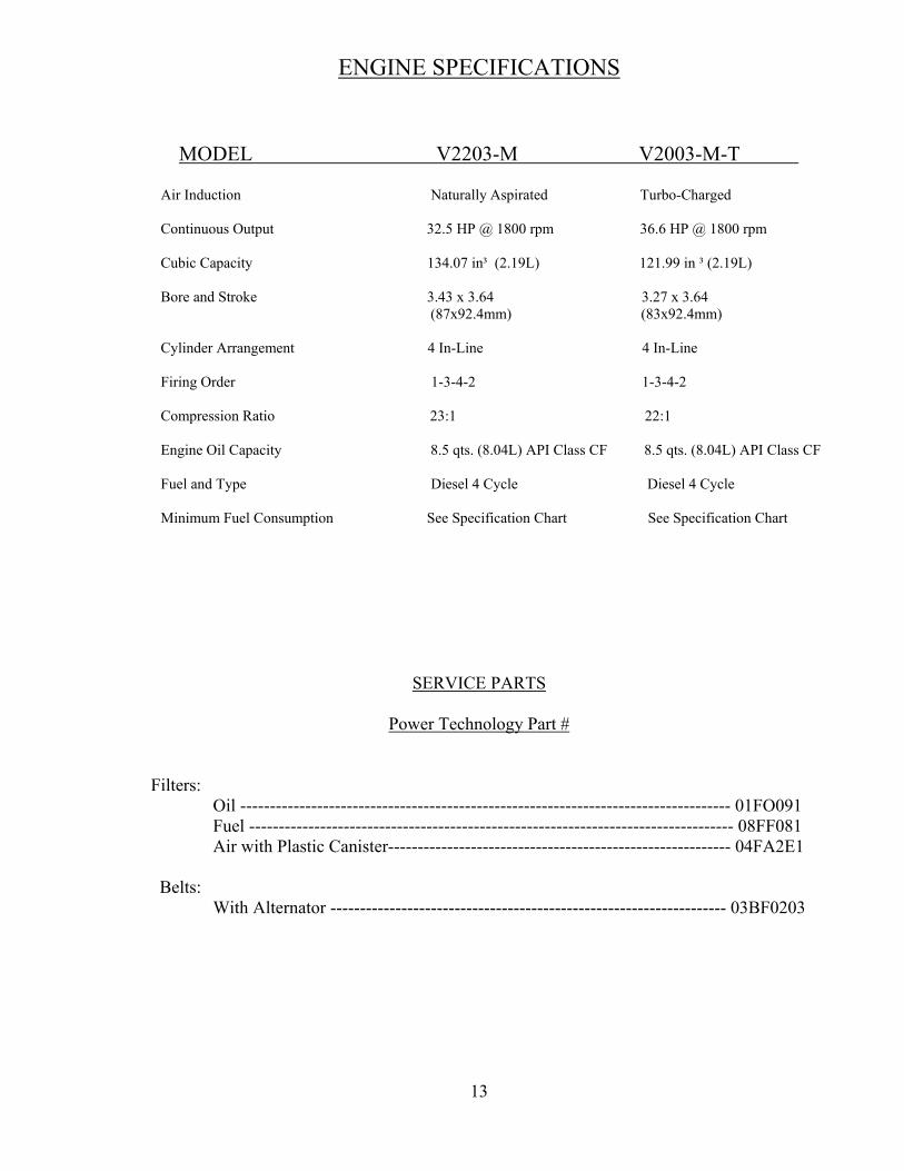
ENGINE SPECIFICATIONS
MODEL V2203-M V2003-M-T
SERVICE PARTS
Power Technology Part #
Filters: Oil ----------------------------------------------------------------------------------- 01FO091 Fuel ---------------------------------------------------------------------------------- 08FF081 Air with Plastic Canister---------------------------------------------------------- 04FA2E1
Belts: With Alternator ------------------------------------------------------------------- 03BF0203
13
Air Induction Naturally Aspirated Turbo-Charged Continuous Output 32.5 HP @ 1800 rpm 36.6 HP @ 1800 rpm
Cubic Capacity 134.07 in³ (2.19L) 121.99 in ³ (2.19L)
Bore and Stroke 3.43 x 3.64 3.27 x 3.64 (87x92.4mm) (83x92.4mm)
Cylinder Arrangement 4 In-Line 4 In-Line
Firing Order 1-3-4-2 1-3-4-2
Compression Ratio 23:1 22:1
Engine Oil Capacity 8.5 qts. (8.04L) API Class CF 8.5 qts. (8.04L) API Class CF
Fuel and Type Diesel 4 Cycle Diesel 4 Cycle
Minimum Fuel Consumption See Specification Chart See Specification Chart

Engine Maintenance Service Schedule
* Engine oil and filter must be changed after the first 50 hours of operation. Then every 150 hours or once a year whichever comes first. ** Air filter replacement interval will vary depending on operating conditions. Adverse conditions may require frequent service. NOTE: Under normal operation items such as Belts, Hoses and Filters are not covered by Power Technology Southeast, Inc. Limited Warranty.
14
Maintenance Service Item
*See Note Daily Every 150
Hours Every 500
Hours Every 1000
Hours Remarks
Engine Oil Level Deterioration & Leakage
X
Engine Oil Change *
X
Or Once a Year
Oil Filter Change *
X
Or Once a Year
Coolant Level X Coolant Leakage X
Coolant Change X Or Once a Year
Fuel Level X As Necessary
Fuel Leakage X Fuel Filter Re- placement
X Or Once a Year
Air Filter Re- placement **
X Or Once a Year
Damaged Worn Or Loose Belts
X
Or Every Two
Years
Replace Fuel Hoses
X Or Every
Two Years
Check Radiator Hoses & Clamps
X
Once a Year
Abnormal Engine Noise
X
Abnormal Generator Noise
X
Muffler Condition
X
Exhaust Gas Condition
X

ENGINE OIL MAINTENANCE
Ambient Temperature Oil Viscosity
Above 25°C (77°F)
SAE 10W-30SAE 30 or
SAE 10W-40 0 to 25°C (32° to 77°F)
SAE 10W-30SAE 20 or
SAE10W-40 Below 0°C (32°F)
SAE 10W-30SAE 10W or
SAE 10W-40
15
CHECKING ENGINE OIL LEVEL
( Y ) “ADD” mark. ( X ) “FULL” mark. 1. Maintain the engine oil level between “ADD” mark and “FULL” mark on oil level gauge. Do not fill crankcase above “FULL” mark. 2. Remove the oil filler cap and add oil, if necessary. Clean the oil filler cap. Install the oil filler cap. The refill capacities for the engine crankcase Reflect the approximate capacity of the crankcase or sump plus a standard oil filter. Auxiliary oil filter systems will require additional oil.
KUBOTA V2203-M & V2003-M-T ENGINE REFILL CAPACITY
Crankcase Oil Sump 8.5 Qts. (8.04L) and Filter
LUBRICATING OIL VISCOSITY RECOMMENDATIONS
The minimum ambient temperature during cold engine start-up and the maximum ambient temperature during engine operation determine the proper SAE viscosity grade of oil. Refer to the Engine Oil Viscosity Table below (Minimum Temperature) in order to determine the required oil viscosity for starting an engine in cold conditions. Refer to the Engine Oil Viscosity Table below (Maximum Temperature) in order to select the oil viscosity for engine operation at the highest ambient temperature that is anticipated.
LUBRICATING OIL SPECIFICATION
Use only good quality
lubricating oil, which meets the following Specification
API Class
CF Engine Oil

ENGINE COOLANT MAINTENANCE
16
COOLANT SERVICE LIFE Coolant Type Service Life Commercial Heavy-Duty Coolant/Antifreeze that 3000 Service Hours Meets “ASTM D5345” or Two Years Commercial Heavy-Duty Coolant/Antifreeze that 3000 Service Hours Meets “ASTM D4985” or One Year NOTE: Do not use a commercial coolant/antifreeze that only meets the ASTM D3306 or D4656 specification. This type of coolant/antifreeze is made for light duty automotive applications.
CHECKING RESERVOIR TANK COOLANT LEVEL
(At a Minimum of 25 Hours of Operation) Ensure that the coolant level of the radiator reservoir tank is between the upper limit (FULL) and the lower limit (LOW) on the side of the reservoir tank.
CLEANING RADIATOR CORE
Visually inspect the core for any obstructions such as dirt or debris. Use running water to clean particles from between fins. IMPORTANT: Never use hard objects to clean radiator core, damage to core could result.
COOLANT RECOMMENDATIONS For optimum performance, Power Technology recommends a 1:1 mixture of water / glycol. NOTE: Use a mixture that will provide protection against the lowest ambient temperature. NOTE: 100 percent pure glycol will freeze at a temperature of –23°C (-9°F). Most conventional heavy-duty coolant / antifreezes use Ethylene Glycol. Propylene Glycol may also be used in a 1:1 mixture with water. Ethylene and Propylene Glycol provide similar protection against freezing and boiling. See the tables below.
ETHYLENE GLYCOL Freeze Boil Concentration Protection Protection 50 Percent -36°C (-33°F) 106°C (223°F) 60 Percent -51°C (-60°F) 111°C (232°F)
PROPYLENE GLYCOL Freeze Boil Concentration Protection Protection 50 Percent -29°C (-20°F) 106°C (223°F)
NOTE: Do not use Propylene Glycol in concentrations that exceed 50 percent glycol because of Propylene Glycol’s reduced heat transfer capability. Use Ethylene Glycol in conditions that require additional protection against boiling or freezing. CHECKING RADIATOR COOLANT LEVEL Remove the radiator cap after the engine has completely cooled and check to see that coolant reaches the supply port.
1. Fill to the bottom of the fill neck and check after every 25 hours of operation.

OPERATING HOURS and SERVICE LOG
THIS SERVICE LOG IS PROVIDED TO HELP YOU KEEP AN ACCUMULATIVE RECORD OF OPERATION HOURS ON YOUR GENERATOR SET AND THE DATES REQUIRED SERVICES WERE PERFORMED. ENTER TIME TO THE NEAREST HOUR.
OPERATING HOURS SERVICE RECORD
DATE HRs. RUN CUMLATIVE DATE SERVICES
17

SECTION 3 “GENERATOR END”
“MAGNAPLUS” SERIES EXCITER TYPE GENERATOR ASSEMBLY 1-20 NOTE: Pages 7 & 8 , 21 & 22 are Omitted. GENERATOR EXPLODED VIEW and PARTS NUMBERS 21 MARATHON SE350 VOLTAGE REGULATOR 22-24 WIRING SCHEMATIC and RESISTANCE CHART ________________________ 25 120 / 240 Volt Connection “M” Series Exciter Type

GENERATOR
280–430 FrameInstallation, Operation,
and Maintenance Manual
Marathon Electric Mfg. Corp.A REGAL-BELOIT COMPANY
P.O. Box 8003Wausau, WI 54402-8003Phone: (715) 675 3359Fax: (715) 675 8026
www.marathonelectric.com

CONTENTSSafety 2Receiving and Storage 2Principles of Operation 3 - 4Installation 4 - 6Wiring Connections 6 - 9Operation 9 - 10Maintenance 11 - 12Testing 12 - 13Service 13 - 15Troubleshooting 15 - 18Specifications 19Parts List & Recommended Spare Parts 20 - 22
SAFETY
PLEASE REMEMBER SAFETY FIRST. If you are not sure ofthe instructions or procedures contained herein, seek qualified help before continuing.
This service manual emphasizes the safety precautions necessary during the installation, operation, and maintenance of your MagnaPLUS® generator. Each section ofthis manual has caution and warning messages. These messages are for your safety, and the safety of the equipmentinvolved. If any of these cautions or warnings are not readily understood, seek clarification from qualified personnel before proceeding.
Before any service work is done, disconnect all powersources and lock out all controls to prevent an unexpectedstart up of the generator set driver. Proper grounding (earthing) of the generator frame and distribution system incompliance with local and national electrical codes and specific site requirements must be provided. These safetyprecautions are necessary to prevent potential serious personal injury, or even death.
The hazards associated with lifting or moving yourMagnaPLUS® generator are pointed out in the installation andmaintenance sections. Incorrect lifting or moving can result inpersonal injury or damage to the unit.
Prior to start up of the unit ensure that all generator leads areproperly connected to the generator link board located insidethe connection box. Always assume that there will be voltagepresent at the generator terminals whenever the generator'sshaft is rotating, and proceed accordingly. Residual voltage ispresent at the generator terminals and at the automatic voltage regulator panel connections even with the regulatorfuse removed. Caution must be exercised, or serious injury ordeath can result.
This manual is not intended to be a substitute for properlytrained personnel. Installation and repairs should only beattempted by qualified, trained people. The cautions andwarnings point out known conditions and situations that arepotentially hazardous. Each installation may well create itsown set of hazards.
When in doubt, ask. Questions are much easier to handlethan mistakes caused by a misunderstanding of the information presented in this manual.
RECEIVING AND STORAGE RECEIVING AND STORAGE
Upon receipt of the generator, it is recommended that it becarefully examined for possible shipping damage. The generator was given to the freight carrier in good condition;thus, the carrier is responsible for the product from the factory dock to the destination. Any damage should be notedon the freight bill before accepting the shipment. Any claimsfor damage must be promptly filed with the delivering carrier.
UNPACKING AND HANDLING
Carefully read all instruction tags shipped with the unit. Whenlifting, attach an overhead crane to the lifting lug(s) on thegenerator frame. Apply lifting forces in a vertical direction.When transporting single bearing generators, the generator’srotor must be adequately supported to prevent damage.
THE LIFTING LUG(S) ON THE GENERATOR AREDESIGNED TO SUPPORT THE GENERATOR ONLY.DO NOT LIFT A COMPLETE GENERATOR AND DRIVER ASSEMBLY BY MEANS OF LIFTING LUG(S)ON THE GENERATOR. PERSONAL INJURY OREQUIPMENT DAMAGE MAY RESULT.
STORAGE
In the event that the generator is not immediately installed onits prime mover, it is recommended that the unit be storedindoors in a clean, dry area which is not subject to rapidchanges in temperature and humidity. If the generator isstored for a long period of time, the generator should be tested, cleaned and dried as required before being put intoservice. See the maintenance section of this manual for further information. If the unit has been stored in an areawhere it has been subject to vibration, it is recommended thatthe bearing(s) be inspected and replaced as necessary.
2

3
PRINCIPLES OF OPERATION
FIGURE 1 -- MagnaPLUS® Circuit Diagram
FIGURE 2 -- Typical MagnaPLUS® Layout Diagram

PRINCIPLE OF OPERATIONMagnaPLUS® generators are brushless, self excited, externally voltage regulated, synchronous AC generator. Thegenerator is made up of six major components: main stator(armature), main rotor (field), exciter stator (field), exciterrotor (armature), rectifier assembly, and voltage regulator. Inunderstanding the above terminology, note the following:stators are stationary, rotors rotate, a field is a DC electricalinput, and an armature is an AC electrical output. These system components are electrically interconnected as shownin Figure 1 and physically located as shown in Figure 2.
The generator’s exciter consists of a stationary field and arotating armature. The stationary field (exciter stator) isdesigned to be the primary source of the generator’s residualmagnetism. This residual magnetism allows the exciter rotor(armature) to produce AC voltage even when the exciter stator (field) is not powered. This AC voltage is rectified to DCby the rotating rectifier assembly and fed directly to the mainrotor (field). As the generator shaft continues to rotate, themain rotor (field) induces a voltage into the generator's mainstator (armature). At rated speed, the main stator’s voltageproduced by the residual magnetism of the exciter allows theautomatic voltage regulator to function. The regulator provides voltage to the exciter field resulting in a build-up of generator terminal voltage. This system of using residualmagnetism eliminates the need for a special field flashing circuit in the regulator. After the generator has established theinitial residual voltage, the regulator provides a controlled DCfield voltage to the exciter stator resulting in a controlled generator terminal voltage.
Voltage Regulation
In the standard configuration (shunt excited), the automaticvoltage regulator receives both its input power and voltagesensing from the generator's output terminals (See Figure 1).With the optional PMG configuration, the regulator receivesinput power from the PMG. The regulator automatically monitors the generator's output voltage against an internalreference set point and provides the necessary DC outputvoltage to the exciter field required to maintain constant generator terminal voltage. The generator's terminal voltageis changed by adjusting the regulator's reference set point.Consult the regulator manual for specific adjustment andoperating instructions.
MOTOR STARTING
When a motor is started, a large surge of current is drawn bythe motor. This starting current is equivalent to the motorslocked rotor or stall current and is 5 to 10 times normal fullload current. When the generator supplies this in-rush ofstarting current, the generator voltage dips temporarily. If themotor is too large for the generator, the generator’s voltagedips greater than 30 percent. This may result in the motorstarter de-energizing or the motor stalling. MagnaPlus®
generators generally supply .3 to .4 horsepower per
generator KW in motor starting capability. For specific datacontact Marathon Electric.
PARALLEL OPERATION
All MagnaPlus® generators are built with 2/3 pitch main stator windings and full amortisseur (damper) windings.These features make the MagnaPlus® generators suitable forparallel operation when equipped with the proper voltage regulators and voltage regulator accessories. Consult with thefactory for further information relative to parallel operations.
NONLINEAR LOADING
Solid state electronic control devices (variable frequencydrives, precision motor controls, battery chargers, etc.) utilizeelectronic switching circuits (thyristors, SCRs, Diodes, etc.).These switching circuits introduce high frequency harmonicswhich distort the normal wave form of the generator. This creates additional heat in the generator windings and maycause the generator to over-heat. Problems which can occurare not limited to the generator. Poor wave shape mayadversely effect various loads connected to the generator.Consult Marathon Electric for further information relative tononlinear loads.
INSTALLATIONPREPARATION FOR USE
Although the generator has been carefully inspected and tested in operation prior to shipment from the factory, it is recommended that the generator be thoroughly inspected.Check all bolts for tightness and examine the insulation onlead wires for chafing prior to proceeding with installation.Remove all shipping tapes, bags, skids and rotor supportblocking. For two bearing units, rotate the shaft by hand toensure that it rotates smoothly without binding.
4

DISABLE AND LOCKOUT ANY ENGINE CRANKINGDEVICES BEFORE ATTEMPTING TO INSTALL ORSERVICE THE GENERATOR. FOR ELECTRIC STARTSETS, DISCONNECT THE CRANKING BATTERY. FORAIR START, DISCONNECT THE AIR SUPPLY. FORMOTOR GENERATOR SETS, OPEN THE POWERSUPPLY TO THE DRIVE MOTOR. FAILURE TO COMPLY WITH THESE SAFETY PROCEDURESCOULD RESULT IN SEVERE PERSONAL INJURY OREQUIPMENT DAMAGE.
NEVER "BAR OVER" THE ENGINE GENERATOR SETUSING THE GENERATOR'S FAN. THE FAN IS NOTDESIGNED FOR THIS PURPOSE. BARRING OVERTHE SET WITH THE FAN COULD DAMAGE THE FANAND RESULT IN PERSONAL INJURY OR EQUIPMENT DAMAGE.
GENERATOR MOUNTINGSingle Bearing Units.
Single bearing units are provided with an SAE flywheel housing adapter flange and flexible drive discs. Coupling thegenerator's shaft to the engine flywheel is accomplished withspecial steel drive discs bolted to the shaft. In addition to thedrive discs, there may be a hub spacer, spacer discs, or acombination of hub spacer and spacer discs insertedbetween the drive discs and the shaft to achieve the propershaft extension ("G" dimension per SAE J620c). Holes areprovided in the periphery of the coupling discs which correspond to tapped holes in the prime mover's flywheel.The outside diameter of the drive discs fit in a rabbet in theflywheel so that concentricity is assured.
Grade 8 place bolts and hardened washers are recommendedto mount the drive discs to the flywheel. DO NOT USE SPLITTYPE LOCK WASHERS. Split lock washers when biting intothe drive disc cause stress risers which may result in the discfracturing.
The SAE flywheel housing adapter ring and the engine flywheel housing are designed to match each other with nofurther alignment necessary. Use grade 5 or greater mounting bolts. MagnaPLUS® generator frames are constructed with two or three bolt holes per foot. The feetshould be shimmed where necessary to obtain solid contractwith the sub-base. With the frame securely bolted to theengine flywheel housing, there is no side thrust or pull on thegenerator frame, thus no real need to secure the feet withmore than one bolt per foot.
GENERATOR MOUNTINGTwo Bearing Generators -- Direct Drive
Two bearing generators are provided with a keyed shaftextension. For direct drive generators, the assembler furnishes a flexible coupling which is installed between thedriver and the generator's shaft. Aligning the generator and itsdriver as accurately as possible will reduce vibration, increasebearing life, and ensure minimum coupling wear. It may benecessary to shim the generator feet for proper support and alignment. Secure the feet of the generator withgrade 5 or greater bolts through the holes provided in themounting feet. Consult the coupling manufacturer's instructions for alignment specifications and procedures.
GENERATOR MOUNTINGTwo Bearing Units -- Belt Driven
Two bearing MagnaPLUS® generators can be belt driven provided belts are sized and applied correctly. Please refer toyour supplier of belts and sheaves for correct sizing and tensioning specifications. A bearing life calculation should beperformed. Marathon Electric recommends a minimum B-10life of 40,000 hours. If cog type belts are used, a vibration maybe introduced which could lead to premature failure of thebearings.
HYDRAULIC DRIVE WITH SHAFT SPLINETwo Bearing Units
All 280 PDL MagnaPLUS® two bearing hydraulic drive generators are equipped with a Zerk grease fitting mounted inthe drive end of the shaft. Prior to assembly to the hydraulicdrive motor, lightly coat the hydraulic drive motor shaft, and/orgrease the generator spline per the greasing instructions inthe MAINTENANCE section, page 12. DO NOT assemblethe generator to the hydraulic drive motor with the splinedry.
END PLAY TESTING
Refer to the engine manual for recommended end play specifications and measurement procedures. If end play isnot to specification, it is an indication that the generator shaftis not moving freely in the assembly, and normal life of thethrust bearing could be impaired. Probable causes of thisproblem are:
1. Improper seating of drive discs in the flywheel resulting inmisalignment.
2. Improper mating of generator frame to engine flywheelhousing resulting in misalignment.
3. Improper "G" dimension per SAE J620c on either theengine or generator.
5

TORSIONAL VIBRATION
Torsional vibrations are generated in all rotating shaft systems. In some cases, the amplitude of these vibrations atcritical speeds may cause damage to either the generator, itsdriver, or both. It is therefore necessary to examine the torsional vibration effect on the entire rotating system. IT ISTHE RESPONSIBILITY OF THE GENERATOR SET ASSEM-BLER TO ASSURE THE TORSIONAL COMPATIBILITY OFTHE GENERATOR AND ITS DRIVER. Drawings showingpertinent dimensions and weights of the rotating assemblywill be supplied by Marathon Electric upon request.
ENVIRONMENTAL CONSIDERATIONS
The MagnaPLUS® generator is designed for heavy duty industrial applications; however, dirt, moisture, heat andvibration are enemies of rotating electrical machinery.Excessive exposure to the elements may shorten generatorlife. The temperature of the cooling air entering the intakeopenings of the generator should not exceed the ambienttemperature shown on the generator’s nameplate. Generatorsintended for outdoor application should be protected withhousings having adequate ventilation. Although the standardinsulation systems are moisture and humidity resistant, spaceheaters are recommended for extreme conditions. If the generator is to be installed in an area where blowing sandand dust are present, the enclosure should be fitted with filters. Filters reduce erosion on the generator's insulation byblocking high velocity abrasive particles generated by the flowof cooling air through the generator. Consult the factory forappropriate filters and generator deratings required.
WIRING CONNECTIONSWiring of the generator and accessories should bedone in accordance with good electrical practices.Follow government, industry and association standards.
The generator conduit box construction allows cable entryfrom multiple sides. A hole saw or other appropriate tool maybe used to provide for conduit entrance. Protect the interior ofthe generator from shavings when drilling or sawing. Anapproved connector must be used in conjunction with theconduit. To minimize the transmission of vibration, it is essential that flexible conduit be used for all electricalentrance to the generator conduit box.
All MagnaPLUS® generators are equipped with link boards(terminal strips) for both internal and external connections. Allconnections made to the studs of the link board should bemade with high quality ring terminals. Ring terminal sizes are:6 mm (280 Series Frames) and 10 mm (360 and 430 SeriesFrames). Torque link board connections to the following specifications: 280 frame -- 5.4 NM (4 Ft Lb); 360 &430 frame -- 27 NM (20 Ft Lb).
Refer to the connection diagram supplied with the generatorand / or the proper diagrams shown in this manual. Install allinter component and external wiring in accordance withnational and local electrical codes. The neutral in the following connection diagrams shown below may be eithergrounded (earthed) or left above ground potential (floating).See national and local codes and / or the system distributionwiring schematic diagram for the proper connection of theneutral.
The following connection diagrams are shown for twelvelead generators. Ten lead generators have the same terminal designations except for leads T10, T11, and T12.These three leads are internally connected inside the generator and brought out as a single lead (T0). Ten leadgenerators can only be connected in a wye configuration.
6
HIGH (SERIES) WYE CONNECTION
L - L0
L - L
L1
L2L3
T1
T4
T7
T3
T6
T9
T12 T10
T11T8
T2
T5
12 Lead
VOLTAGE (HIGH WYE)Hz L-L L-Lo60 380 219
416 240440 254460 266480 277
50 380 219400 231415 240440 254

9
DEDICATED SINGLE PHASE CONNECTIONHIGH VOLTAGE - SERIES CONNECTED
VOLTAGE (DEDICATED)Hz L-L L-N60 240 120
220 11050 220 110
200 100
SINGLE PHASE CONNECTION - SINGLE VOLTAGE PARALLEL
VOLTAGEL-L
60 HZ 12050 HZ 110
Note: For 120 volt only service. Use an AVC63-4A or a VR63-4C voltage regulator toreplace the standard SE350 regulator.

OPERATION
PRE-START INSPECTION
Before starting the generator for the first time, the followinginspection checks are recommended:
1. A visual inspection should be made for any loose parts,bad connections, or foreign materials.
2. Bar the set over by hand for at least 2 revolutions to besure that there is no interference and that the set turnsfreely. If the set does not turn freely, check for clearancein the generator and exciter air gap.
3. Check all wiring against the proper connection diagrams,and ensure that all connections and terminations aretight and properly insulated.
4. Verify that all equipment is properly grounded (earthed).
MAGNAPLUS® GENERATORS MAY HAVE VOLTAGE PRESENT AT THE LEAD TERMINALS WHEN THESHAFT IS ROTATING. DO NOT PERMIT OPERATIONOF THE GENERATOR UNTIL ALL LEADS HAVEBEEN CONNECTED AND INSULATED. FAILURE TODO THIS MAY RESULT IN PERSONAL INJURY OREQUIPMENT DAMAGE.
5. Clear the surrounding area of any materials that could bedrawn into the generator.
6. Check all fasteners for tightness.
7. Check all access plates, covers, screens and guards. Ifthey have been removed for assembly or inspection, reinstall and check for security.
8. Review all prime mover prestart up instructions, andensure that all recommended steps and procedures havebeen followed.
9. Remove any masking materials affixed during painting.Inspect the generator, prime mover, and any accessoryequipment to ensure that nameplates, and all safetywarning / caution signs and decals provided with theequipment are in place and clearly visible.
Note: It is strongly recommended that the authority having jurisdiction over the installation site be consulted to determine if any additional warning orcaution notices, or additional safety devices arerequired by local codes / standards. Any suchrequired notices or devices should be installed priorto initial startup.
START-UP
The following procedure should be followed when starting thegenerator set for the first time.
1. The generator output must be disconnected from theload. Be sure that the main circuit breaker or fused disconnect is in the open position.
2. Open the input power to the automatic voltage regulator. Remove the fuse or disconnect and insulateone of the regulator input power leads. (See separateregulator manual)
3. Verify that all prime mover start-up procedures havebeen followed.
4. If the unit is provided with space heaters, ensure thatthey are de energized. In some installations, a set of auxiliary contacts on the main circuit breaker or transferswitch will automatically open the space heater circuitwhen the generator is connected to the load.
5. Start the prime mover, and adjust it for proper speed. Seegenerator nameplate.
6. The purpose of this initial test with the regulator out of thecircuit is to detect any wiring mistakes without exposingthe unit to undue risk. Check all line to line and line toneutral voltages for balanced voltage. If voltages are balanced, shut down the set and reconnect the regulator. If voltages are unbalanced, shut down theequipment and check for improper wiring. If the problem persists, consult the factory.
With the regulator de energized, the residual voltageshould be 10 - 25% of rated value. It is recommendedthat this residual voltage and driver RPM be recorded foruse as a future troubleshooting benchmark.
THE FOLLOWING TEST MUST BE CONDUCTED BY QUALIFIED ELECTRICAL PERSONNEL. LETHALVOLTAGE MAY BE PRESENT AT BOTH THE GENERATOR AND VOLTAGE REGULATOR TERMINALS DURING THIS PROCEDURE. CAUTIONMUST BE EXERCISED NOT TO COME INTO PERSONAL CONTACT WITH LIVE TERMINALS,LINKS, OR STUDS. SERIOUS INJURY OR DEATHCOULD RESULT.
7. Start the set and adjust the terminal voltage to thedesired value by means of the regulator voltage adjustment. If the regulator is equipped with a stabilityadjustment, follow the instructions in the regulator manual to adjust the stability. Again, check all line to lineand line to neutral voltages for balance. It is
10

recommended practice to record the no load excitation(DC voltage to the exciter stator), generator terminal voltage, and driver speed as a benchmark for future troubleshooting.
8. Close the main circuit breaker to the load.
9. Monitor the generator output current to verify that it is ator below nameplate value.
10. Check generator speed (frequency) under load. Adjust asnecessary. (Refer to prime mover or governor manuals)
SHUTDOWN PROCEDURE
There are no specific instructions for shutting down the generator; however, several good practices should beobserved to prolong equipment life.
1. It is advisable to disconnect all loads (open main circuitbreaker or disconnect) prior to shutdown. This is especially important if loads can be damaged by low voltage or low frequency conditions during generator"coast down".
2. Isolate all conditions that could apply voltage to the generator terminals while the generator is at rest. Failureto comply could result in personnel injury or equipmentdamage.
3. If the unit is equipped with space heaters, verify that theheater circuit is energized.
MAINTENANCEThe following maintenance procedures should be followed toensure long equipment life and satisfactory performance.Maintenance intervals will depend upon operating conditions.
1. Routinely check intake and exhaust air screens to ensurethat they are clean and free of debris. Clogged intake airscreens will reduce cooling air flow and result in higheroperating temperatures. This will reduce generator lifeand may result in generator damage.
2. All MagnaPLUS® generators are equipped with doubleshielded ball bearings lubricated for the life of the bearing. Every 1,000 hours check the bearing(s) forsmooth, quiet operation. For continuous duty generators,recommended practice is to replace the bearing duringmajor overhauls of the engine.
3. Periodically inspect the unit for any buildup of contamination (dirt, oil, etc.) on the windings. If thewound components have become coated with heavyconcentrations of oil and grime, the unit should be disassembled and thoroughly cleaned. This operation isnot one that can be accomplished effectively on site, but
rather one that should be conducted by an authorizedservice center equipped with the appropriate apparatusand solvents necessary to properly clean and dry thegenerator.
THE FOLLOWING TEST MUST BE CONDUCTED BY QUALIFIED ELECTRICAL PERSONNEL. LETHALVOLTAGE MAY BE PRESENT AT BOTH THE GENERATOR AND VOLTAGE REGULATOR TERMINALS DURING THIS PROCEDURE. CAUTIONMUST BE EXERCISED NOT TO COME INTO PERSONAL CONTACT WITH LIVE TERMINALS,LINKS, OR STUDS. SERIOUS INJURY OR DEATHCOULD RESULT.
4. Every 2,000 operating hours or in conjunction withscheduled engine maintenance, check the DC no loadexcitation voltage per item #7 in the startup procedure.Compare this voltage with the value recorded during initial startup. If this value of no load excitation voltage ismarkedly higher than the bench mark reading, it is anindication of problems in either the exciter, main field, orthe rotating rectifier assembly. Ensure that RPM is thesame as initial test.
5. Monitor and record insulation resistance with a 500 voltmega-ohm meter. The minimum acceptable reading is 2mega-ohms. If the reading drops below the minimum, thegenerator should be cleaned and dried at an authorizedservice shop. Consult Marathon Electric for more information.
DRYING WINDINGS
Generators in service may inadvertently have their windingsexposed to splashing or sprayed water. Units that have beenin transit or storage for long periods of time may be subjected to extreme temperature and moisture changescausing excessive condensation. Regardless of the source ofmoisture, wet windings should be thoroughly dried out beforeoperating the unit. If this precaution is not taken, serious damage to the generator can result. The followingprocedures may be utilized in drying the generator’s windings. The method selected will be influenced by windingwetness and situation limitations.
Space HeatersAn electric heater may have been supplied with the generator. When energized from a power source other thanthe generator, the heater will gradually dry the generator. Thisprocess can be accelerated by enclosing the unit with a covering and inserting additional heating units. A hole shouldbe left at the top of the covering to permit the escape of moisture. Care should be taken not to overheat variousaccessory equipment mounted with the generator.
11

Forced AirAnother method to dry the generator is to run the set with noexcitation (see startup procedure item #2). The natural flow ofambient air through the generator will tend to dry the windings. This method can be accelerated by adding a sourceof heat at the air intake to the generator. Heat at point of entryshould not exceed 80 C (180° F).
HYDRAULIC DRIVE GENERATORS,SHAFT SPLINE LUBRICATION
The shaft spline should be greased prior to initial assembly tothe driver, and every three (3) months to reduce maintenance,and prolong the life of the spline coupling per the followingprocedure:
1. Material: Molybdenum Disulfide - sometimes referred toas “Molly Grease.”
2. Turn the rotor assembly so that the Zerk fitting is in linewith the access hole in the top of the drive end bearingbracket as illustrated in Figure 3.
3. Using a hand held grease gun with a solid coupling,apply a small amount of grease into the fitting. DO NOTOVER GREASE. Limit the amount of grease to one (1)trigger pull of the grease gun.
Figure 3--Drive End Bearing Bracket
TESTINGVisual Inspection
Remove covers and look for any obvious problems: burntwindings, loose connections, broken wires, frayed insulation,cracked brackets, missing hardware, etc. Check for foreignobjects which may have been drawn into the generator. Verify
that the generator’s air gaps (main rotor and exciter) are freefrom obstructions. If possible, rotate the generator manuallyto ensure free rotation. Never “bar over” the engine generatorset using the generator fan.
THE FOLLOWING TEST MUST BE CONDUCTED BY QUALIFIED ELECTRICAL PERSONNEL. LETHALVOLTAGE MAY BE PRESENT AT BOTH THE GENERATOR AND VOLTAGE REGULATOR TERMINALS DURING THIS PROCEDURE. CAUTIONMUST BE EXERCISED NOT TO COME INTO PERSONAL CONTACT WITH LIVE TERMINALS,LINKS, OR STUDS. SERIOUS INJURY OR DEATHCOULD RESULT.
CONSTANT EXCITATION TEST(12V BATTERY TEST)
The generator “no load” voltage is dependent on exciter inputvoltage and generator speed. With the generator operating atrated speed and 12 volts dc applied to the exciter field, thegenerators terminal voltage will be near rated value.
1. Shutdown the generator set and connect a voltmeter onthe generator terminals.
2. Disconnect the regulator’s F+ (F1) and F- (F2) leads andconnect them to a 12V battery. Caution should be takento ensure that the battery is not exposed to any potential arcing.
3. With no load on the generator (main breaker open) runthe generator at rated speed. Measure the generator’sterminal voltage and compare this value with valuesrecorded during installation.
If voltage readings are normal, the main generator and excitation are operating properly. Troubleshooting should continue with the regulator. If readings are not normal theproblem is in the generator. Continue testing diodes, surgesuppressor, and windings.
Continuity / Resistance Test
The generator has four components which can be checkedusing an ohm meter: exciter stator, exciter rotor, main statorand main rotor. Each of these components are comprised ofvarious windings which form a complete electrical path of relatively low resistance. Using an ohm meter measure theloop resistance of each component. Compare these measured values with the values listed in the specificationsection of this manual. Note that very small resistance valuesrequire precision equipment to make accurate measurements; however, a standard ohm meter will provide agood indication of winding continuity.
12
Shaft MountedZerk Fitting
Grease GunAccess Hole

Insulation Test
Insulation resistance is a measure of the integrity of the insulating materials that separate the electrical windings fromthe generator’s steel core. This resistance can degrade overtime or be degraded by contaminants: dust, dirt, oil, grease,and especially moisture. Most winding failures are due to abreakdown in the insulation system. In many cases, low insulation resistance is caused by moisture collected whenthe generator is shutdown
Insulation resistance is measured with a megger (mega-ohmmeter). A megger measures insulation resistance by placing500 volts between the winding and the frame of the generator. Caution must be taken to remove all electronicdevices (regulators, diodes, surge protectors, capacitors, protective relays, etc.) from the winding circuit before checking the insulation. Winding insulation can be checked onthe main stator, main rotor, exciter stator, and exciter rotor.Minimum resistance is 2 mega-ohms. If the winding resistance is low it must be dried (see maintenance section)or repaired.
DIODE TESTING
If the generator is close coupled to an engine, it may be necessary to "bar over" the engine in order to gain access toa given area of the rectifier assembly. NEVER use the generator's fan as a fulcrum to accomplish this. Use theengine manufacturer's recommended practice to manuallyturn over the engine. To prevent possible injury to personnel,and damage to the equipment, ensure that the engine cannot start during this procedure.
Remove the two main rotor leads and the three exciter rotorleads from the rectifier assembly (Figure 5). The rectifierassembly is now electrically isolated from the generator. Thediodes remain mounted and the diode leads remain connected to the terminal posts. Using an ohmmeter or a battery light continuity tester, place one test probe on thediode lead terminal post. In succession, touch the other testprobe to the lead screw hole in each heat sink. Reverse theprobes and repeat the procedure. You have now tested thethree diodes connected to this terminal post in both the forward and reverse direction. Repeat the procedure usingthe other diode terminal post.
FIGURE 4: DIODE POLARITY
When the positive test probe is connected to the diode'sanode and the negative test probe is connected to the diode'scathode (forward biased), the diode will switch on and conduct electricity (Figure 4). This is observed by a low resistance reading when using an ohm meter or the lightingof the bulb when using a battery light continuity tester.Reversing the test leads (reverse biased) will result in thediode switching off and no electricity will be conducted. Theresults of these tests should indicate one of three conditions:
1. Good diode: Will have a much greater resistance in onedirection than the other.Typical reverse biased resistancewill be 30,000 ohms or greater, while forward biasedresistance will be less than 10 ohms. The battery lighttester will have the light "on" in one direction and "off" inthe other.
2. Shorted condition: Ohmmeter reading will be zero, orvery low in both directions. The continuity tester will havethe light "on" in both directions.
3. Open condition: Ohmmeter will have a maximum (infinity) reading in both directions. Continuity tester lightwill be off in both directions.
Diode failure after a 25 hour "run in" period is generally traceable to external causes such as a lightning strike,reverse current, line voltage spikes, etc. All 6 diodes areessentially in the same circuit. When a diode is stressed tofailure, there is no easy method to determine remaining life inthe other diodes. To avoid possible continued failures, it is recommended that the entire rectifier assembly be replacedrather than replacing individual diodes.
SERVICE
GENERAL
The service procedures given in this section are those whichcan reasonably be conducted on-site with a minimum number of special tools and equipment. All service procedures should be conducted by qualified maintenancepersonnel. Replacement parts may be ordered through anauthorized service center or directly from the factory.
FIELD FLASHINGRestoring Residual Magnetism(not applicable on PMG equipped generators)
To restore residual magnetism to the generator, connect a 12volt battery to the exciter field while the generator using thefollowing procedure:
1. Shutdown the generator set. Remove the exciter fieldleads F+ and F from the regulator.
13
Terminal EndTerminal End
AnodeAnode(+)(+)
CathodeCathode(-)(-)
Stud EndStud End
CathodeCathode(-)(-)
AnodeAnode(+)(+)
ForwardForward ReverseReverse

Failure to remove the exciter field leads from the automatic voltage regulator during flashing procedures may destroy the regulator.
2. Connect the F+ and F- leads to the battery’s corresponding positive and negative terminals. Thisshould be done using an appropriate length of lead wireto separate the battery from the point of connection (batteries may explode when exposed to an electric arc).After 3 to 5 seconds, remove the F- lead. An inductive arcshould result. If no arc is drawn, repeat the procedure.
3. Reconnect the F+ and F- leads to the regulator. Restartthe generator and verify that terminal voltage is developed. If terminal voltage does not develop, repeatthe field flashing procedure and / or consult the troubleshooting section.
BEARING REMOVAL
Prior to performing this operation, it is suggested that thealternator's shaft be rotated until two of the main rotor polesare in a vertical position. Once the bearing bracket is backedout, the rotor will drop on the main stator core. Having therotor in this position will limit the amount of rotor drop to thatof the air gap. Visually inspect the bearing bore for damage orwear. If worn or damaged, replace prior to reassemble.
Opposite Drive End Bearing Bracket Removal.Prior to proceeding with bracket removal, disconnect exciterfield leads F+ and F- from the automatic voltage regulator andensure that they are free to move when the bearing bracket isremoved. Remove the bearing bracket retaining bolts. Using apair of screw drivers, wedge the bracket off the frame. Afterapproximately 1/8 inch, the bracket will clear the locating register on the frame and will drop until the rotor is resting onthe main stator core. Continue to pull the bracket free from thebearing. Visually inspect the bearing bore and o-ring (ifequipped) for damage or wear. If worn or damaged, repair orreplace prior to reassembly.
Drive End Bearing Bracket Removal,Two Bearing Units.Remove any drive arrangement from the generator shaftextension. Remove the bearing lock ring retaining screws.There is no o-ring in the drive end bearing bracket. The shaftextension must be supported before proceeding further. Ahoist and sling, jack, or some other means of support with acapacity of 2 tons should be used.
Remove the bearing bracket retaining cap screws. Using a flatbladed screw driver or chisel, pry the bracket back from theframe. After approximately 1/8 inch, the bracket will clear thelocating register on the frame. Lower the shaft extension untilthe rotor is resting on the main stator core. Continue to pullthe bracket free from the bearing. Visually inspect the bearing bore for damage or wear. If worn or damaged, sleeveor replace prior to reassembly.
Reassembly note: Before the bearing bracket is seatedagainst the frame, a threaded rod may be used to help alignthe inner bearing cap with the bearing bracket.
BEARING REPLACEMENT
Using a bearing puller, remove the existing bearing. It isstrongly recommended that the bearing be replaced any timethe it is removed from the shaft. ALWAYS install the sametype and size bearing that was supplied as original equipment. Order by part number from the parts list, andinclude the unit serial number and part number when ordering. Heat the bearing to a maximum of 100°C (212°F) inan oven. Apply a thin coat of clean lubricating oil to the pressfit area of the rotor shaft. Using suitable heat resistant gloves,install the bearing over the end of the shaft until it seatsagainst the shaft shoulder. The bearing should slide on theshaft and be seated without excessive force. Should the bearing bind on the shaft prior to being seated against theshoulder, a piece of tubing slightly larger than the press fitarea can be used to drive the bearing to its final position.Using light taps with a soft mallet, apply pressure to the innerrace only.
RECTIFIER ASSEMBLY REMOVAL
The rectifier assembly cannot be removed until the oppositedrive end bearing bracket and bearing have been removed(see bearing removal procedure). Remove the three exciterrotor leads from the heat sinks and the two main rotor leadsfrom the main rotor posts (see Figures 5). Remove the screwssecuring the rectifier assembly and pull the assembly freefrom the shaft.
DIODE REPLACEMENT
Prior to installing a replacement diode on the heat sink, applya thin film of conductive heat sink compound around the baseof the diode (do not coat the threads). When installing a diodeon the heat sink, care should be taken not to over torque theretaining nut which could cause damage to the device. Torqueto 28 pound inches. If not damaged, the existing diode leadwire may be unsoldered from the failed diode, and resolderedon the replacement.
14

RETURNED GOODS
Contact Marathon Electric Manufacturing Corporation forauthorization before returning any product. We can not beresponsible for any items returned without authorization.
Single bearing generators must have their rotor assembly properly secured to prevent damage duringtransit to the factory, or to an authorized service cen-ter.
TROUBLESHOOTING This section is intended to suggest a systematic approach tolocating and correcting generator malfunctions. The section isarranged according to the symptoms of the problem. Thesteps have been arranged in an attempt to do the easychecks first and prevent further damage when troubleshooting a disabled machine.
The first step of troubleshooting is to gather as much information as is possible from operating personnel and individuals present during the failure. Typical informationincludes: how long the unit had been operating; what loadswere on line; weather conditions; protective equipment thatdid or did not function. In addition, information as to the operating condition of the generator's prime mover is vital.Has the prime mover been maintaining constant speed? Ifnot, have there been extended periods of under speed operation? Has the prime mover experienced an over-speedcondition? If yes, what was the maximum speed, and howlong did the unit operate at that elevated speed?
The generator speed should be maintained at rated nameplate value during all operating tests. The frequency ofthe generator depends upon rotational speed. Most regulators used with MagnaPLUS® generators have built inunder frequency protection such that if the speed is reducedmore than 5%, the voltage will drop off rather rapidly with further reductions in speed.
15
430 FRAME 280 / 360 FRAMEA - Exciter Rotor Lead, B - Main Rotor Lead, C - Red (+) Suppressor Lead, D - Black (-) Suppressor Lead
FIGURE 5: ROTATING RECTIFIER ASSEMBLY

HIGH VOLTAGES MAY BE PRESENT AT THE GENERATOR’S TERMINALS WHEN THE UNIT IS RUNNING. SOME ACCESSORY EQUIPMENT SUCH AS SPACE HEATERS MAY BE ENERGIZED FROM AN OUTSIDE POWER SOURCEWHEN THE UNIT IS AT REST. TOOLS, EQUIPMENT, CLOTHING AND YOUR BODY MUST BE KEPT CLEAR OF ROTATING PARTS AND ELECTRICAL CONNECTIONS. SPECIAL PRECAUTIONS MUST BE TAKEN DURING TROUBLESHOOTING SINCE PROTECTIVE COVERS AND SAFETY DEVICES MAY BE REMOVED OR DISABLED TOGAIN ACCESS AND PERFORM TESTS. BE CAREFUL. SERIOUS PERSONAL INJURY OR DEATH CAN RESULT FROMTHESE HAZARDS. CONSULT QUALIFIED PERSONNEL WITH ANY QUESTIONS.
GENERATOR PRODUCES NO VOLTAGECAUSE CHECK AND REMEDY
Voltmeter off or defective Check voltage with a separate meter at the generator terminals.
Incorrect or defective connections Verify generator connections. See drawings supplied with the generator or lead connection diagrams in this manual. Inspect all wiring for loose connections, open circuits, grounds, and short circuits.
Loss of residual Flash the field. Refer to field flashing in the service section. If the generator is equippedwith a PMG, field flashing is not necessary -- check regulator fuse and input powerfrom the PMG.
Defective diodes, suppressor, or windings Test the generator using the 12 volt battery test as specified in the testing section. Ifthe results indicate generator problems, perform insulation, continuity, and diode testsas specified in the testing section.
Regulator protection operating Adjust regulator. Consult regulator manual.
Regulator inoperative Adjust or replace regulator. Consult regulator manual.
GENERATOR PRODUCES LOW VOLTAGE, NO LOADCAUSE CHECK AND REMEDY
Underspeed operation Check speed using a tachometer or frequency meter.
Voltmeter off or defective Check voltage with a separate meter at the generator terminals.
Incorrect or defective connections Verify generator connections. See drawings supplied with the generator or lead connection diagrams in this manual. Inspect all wiring for grounds, open circuits andshort circuits.
Loss of regulator power Check regulator fuse and input power. Input power is produced by the generator’sresidual voltage or from an optional PMG.
Regulator adjustment Adjust regulator settings. Consult regulator manual.
Regulator incorrectly connected Review the generator connection diagram or reference the regulator manual.
Defective diodes, suppressor, or windings Test the generator using the 12 volt battery test as specified in the testing section. Ifthe results indicate generator problems, perform insulation, continuity, and diode testsas specified in the testing section.
Regulator inoperative Adjust or replace regulator. Consult regulator manual.
16
WARNING

GENERATOR PRODUCES LOW VOLTAGE WHEN LOAD APPLIEDCAUSE CHECK AND REMEDY
Excessive load Reduce load. The load on each leg should be evenly balanced, and rated currentshould not be exceeded on any leg.
Large motor starting or low Motor starting currents are too large for the generator. When starting multiple motors, load power factor sequence the motors and start the largest motors first. Reduce lagging power factor
load.
Driver speed droop or belt slip Check driver. If belt driven, check belt tension. Check under frequency setting on regulator. Under frequency voltage roll-off may be activated.
Reactive droop If the generator is equipped for parallel operation, some droop is normal as reactiveload increases. When operating as a single unit, the parallel CT can be shorted toeliminate this effect. Refer to Regulator manual.
Line drop If voltage is proper at generator terminals but low at load terminals, increase externalwire size.
Defective diodes, suppressor, or windings Test the generator using the 12 volt battery test as specified in the testing section. Ifthe results indicate generator problems, perform insulation, continuity, and diode testsas specified in the testing section.
GENERATOR PRODUCES FLUCTUATING VOLTAGECAUSE CHECK AND REMEDY
Fluctuating engine speed Check engine and governor systems for malfunctions. Check load for fluctuation.
Regulator stability Adjust Regulator stability. Refer to Regulator manual.
Regulator external rheostat Replace defective or worn rheostat. Use shielded cable to minimize electrical noise.
Defective rectifier assembly Check assembly for loose connections. Test the diodes as specified in the test section.
Loose terminal or load connections Improve connections both mechanically and electrically.
Defective regulator Replace regulator.
GENERATOR PRODUCES HIGH VOLTAGECAUSE CHECK AND REMEDY
Faulty metering Check voltage with separate meter at generator terminals.
Incorrect connections Verify generator connections. Refer to drawings supplied with the generator or connection diagrams in this manual.
Regulator adjustments Adjust regulator. Consult regulator manual.
Leading power factor Check the power factor of the load. If power factor is leading, change load configuration. Excessive leading power factor (capacitors) can cause voltage to climbout of control.
Incorrect regulator connection Verify regulator voltage sensing is connected correctly. Consult regulator manual.
Defective regulator Replace regulator.
17

GENERATOR BUILDS VOLTAGE FROM STARTUP,THEN GOES TO LOW (RESIDUAL) VOLTAGE
CAUSE CHECK AND REMEDY
Regulator protective circuit operating Check indicators on regulator. Correct problems and adjust regulator as is required.Refer to regulator manual.
GENERATOR IS OVERHEATINGCAUSE CHECK AND REMEDY
Generator is overloaded Reduce load. Check with ammeter and compare with nameplate rating.
Clogged ventilating screens Clean air passages.
High room temperature or altitude Improve ventilation or reduce load.
Insufficient circulation of cooling air Generator location and enclosure design must provide adequate air flow and minimize recirculation of hot air.
Unbalanced load The load on each leg should be as evenly balanced as possible and should not exceedrated current on any one leg.
GENERATOR PRODUCES MECHANICAL NOISECAUSE CHECK AND REMEDY
Defective bearing Replace bearing.
Loose or misaligned coupling Tighten, realign, or replace coupling.
Belt slap or loose guards Check belt tensioning. Check belt guard fasteners.
EQUIPMENT RUNS NORMALLY ON UTILITY POWER,BUT WILL NOT RUN ON GENERATOR SET
CAUSE CHECK AND REMEDY
Distorted voltage waveform Analyze load. Excessive SCR (thyristor) loading will cause distortion. Some equipmentmay be sensitive to distorted waveforms. Refer to Marathon Electric..
Improper generator voltage or frequency Check name plates of devices comprising the load. Compare required voltage and frequency with that of the generator. Adjust driver speed and/or generator voltage asnecessary to match generator output to load requirements.
Compare required voltage, frequency, and KVA with generator nameplate to ensure adequate generator capacity. If indoubt, consult Marathon Electric for information regarding generator capacity.
18

SPECIFICATIONS
19
MODEL / FRAME SIZEEXCITER RESISTANCE
STATOR ROTOR281, 282, 283, 284, 285, 286, 287 18.0 .120361, 362, 363 -- three phase 23.5 .120361, 362, 363 -- dedicated single phase 23.0 .135431, 432, 433 -- three phase 18.5 .120431, 432 -- dedicated single phase 18.0 .105
EXCITER FIELDMODEL GENERATOR RESISTANCE NO LOAD VOLTS
STATOR* ROTOR 480 V / 60 HZ
281PSL1500 4.20 .400 11.0
281PSL1501 4.15 .400 11.0
281CSL1502 0.47 0.72 6.40
281PSL1502 3.20 .439 9.0
282PSL1703 1.07 0.34 14.70
282CSL1504 1.24 0.80 6.20
282PSL1704 1.07 0.34 14.70
282CSL1505 0.87 0.90 5.80
282PSL1705 0.74 0.37 14.35
283CSL1506 0.54 1.00 8.20
283PSL1706 0.45 0.40 12.95
283CSL1507 0.44 1.18 9.20
283PSL1707 0.39 0.46 11.20
284CSL1508 0.29 1.36 10.00
284PSL1708 0.27 0.52 14.18
284CSL1542 0.27 1.36 8.30
284PSL1742 0.22 0.54 14.00
285PSL1700 0.20 0.58 11.90
286PSL1701 0.14 0.72 10.68
287PSL1702 0.12 0.79 10.9
361CSL1600 .381 .750 11.8
361CSL1601 .264 .810 12.5
361CSL1602 .181 .990 14.1
362CSL1604 .138 1.05 12.2
362CSL1606 .098 1.20 10.8
363CSL1607 .069 1.37 12.2
431CSL6202 .021 .811 15.1
431CSL6204 .048 .637 13.6
431CSL6206 .037 .679 13.82
431CSL6208 .013 .715 12.20
432PSL6210 .021 .811 15.1
432PSL6212 .023 .866 14.1
433PSL6216 .012 1.067 16.2
433PSL6220 .012 .974 15.6
DEDICATED EXCITER FIELDSINGLE GENERATOR RESISTANCE NO LOAD VOLTSPHASE STATOR ROTOR 480 V / 60 HZ
281PSL1500 4.20 .400 11.0
281CSL1513 0.47 0.72 4.3
281PSL1511 1.420 .381 8.3
281PSL1512 1.106 .395 8.1
281PSL1513 .632 .430 8.7
282CSL1515 0.21 0.82 6.2
282PSL1714 0.19 0.35 13.0
282PSL1715 0.19 0.35 13.0
282PSL1716 0.11 0.36 12.4
283CSL1517 0.08 1.14 12.7
283PSL1717 0.5 0.41 11.8
283PSL1718 0.07 0.46 10.1
284CSL1518 0.06 1.41 12.5
284CSL1550 0.05 1.48 16
284PSL1750 0.05 0.55 11.1
285PSL1711 0.04 0.58 11.0
286PSL1712 0.03 0.71 9.7
287PSL1713 0.02 0.78 12.3
361PSL1611 .070 .750 17.5
361PSL1612 .043 .857 16.1
361CSL1613 .037 .926 13.6
362CSL1615 .019 1.20 17.0
363CSL1617 .012 1.35 23.0
431PSL6222 .025 .516 9.9
431PSL6224 .013 .615 13.8
431PSL6226 .009 .643 15.1
432PSL6228 .007 .852 11.2
* Stator resistance measured line to line in a high wye connection.

20
PARTS LIST – SINGLE BEARINGTypical Generator Cross Section
1
2
3
4
5
7
6
8 9 1110 12 13 14 15
17
18
16
20 19
Reference Part Name Reference Part NameNumber Number
1 End Bracket (under end cover 360 & 430 frames) 11 Main Stator2 Bearing 12 Main Rotor3 O-ring (280 and 360 frame only) 13 Rotor Integral Keyway4 Rectifier Assembly 14 Fan5 Air Intake Cover 15 Mounting Adapter (SAE)6 Exciter Rotor 16 Shaft7 Exciter Stator 17 Drive Hub8 Link Board (terminal block) 18 Drive Disk (SAE)9 Conduit Box 19 Exhaust Screen (drip cover not shown)10 Generator Frame 20 Mounting Base
Note: Illustration above is a 360 frame MagnaPLUS®. Other Frame sizes are typical. Optional PMG not shown. The generatormodel and serial numbers are required when ordering parts.

DESCRIPTION PART NUMBER 1. END COVER 02HB30 2. ROTOR BEARING 02BRG30 3. EXCITER ROTOR 02RTR30EXC 4. EXCITER STATOR 02STA30EXC 5. GENERATOR ASSEMBLY 02GEN1517 VOLTAGE REGULATOR 06REG350SE
“MAGNAPLUS” SERIES EXCITER TYPE GENERATOR ASSEMBLY
21

MARATHON SE350 VOLTAGE REGULATOR The SE350 electronic voltage regulator is designed to control the output of a brush less AC generator by regulating the current into the exciter field. Features include frequency compensation, automatic voltage build-up and EMI suppression. The SE350 attaches to the generator with spade type wire terminals for a secure connection. The SE350 has three adjustable potentiometers for fine-tuning the output voltage, stability and under frequency. The regulator is encapsulated in a protective plastic shell and back filled with a sealing compound, which provides protection from environmental hazards. SE350 Specifications: Sensing and Power Input 190 – 240V AC Burden 500VA Output Power – Continuous 73V DC at 3.5 Amps DC (255W) Output Power – Forcing 105V DC at 5 Amps DC (525W) (240V AC input Power) Regulation 1.0% Frequency Compensation Adjustable Roll Off Frequency 54 - 61 Hz for 60 Hz Operation 45 - 51 Hz for 50 Hz Operation Voltage Build-Up Internal provisions for automatic voltage build-up From generator residual voltage as low as 10V AC EMI Suppression Internal Electromagnetic Interference Filter (EMI Filter)
22
3 ADJUSTABLE POTENTIOMETERS, ACCESSED FROM OTHER SIDE
JUMPER JUMPER

MARATHON SE350 VOLTAGE REGULATOR
WARNING: To prevent personal injury or equipment damage, only a qualified service technician should install, operate or service this device. IMPORTANT: DO NOT megger or high-pot the generator while the regulator is connected. DO NOT high-pot the regulator. VOLTAGE ADJUST: A screwdriver adjustable potentiometer adjusts the generator output voltage. Adjustment clockwise increases the generator output voltage. STABILITY ADJUST: System stability is the ability of the generator to respond to load transients. Decreasing the stability makes the generator less sluggish and faster to respond to load transients. If the stability of the regulator is decreased too much, the generator will tend to hunt under steady state conditions. A screwdriver adjustable potentiometer adjusts the system stability. Adjustment clockwise increases the stability. Increasing the stability increases the response time of the generator. Conversely, decreasing the stability decreases the response time of the generator. V/HZ ROLL-OFF FREQUENCY SELECTION: The roll-off point is the frequency where the generator voltage starts to decrease. This reduces the Kilowatt load to the engine, which allows the engine to recover in speed under any load transient condition. Use jumper to select 50 Hz or 60 Hz. The screwdriver adjustable potentiometer sets the roll-off frequency from 54-61 Hz in the 60 Hz setting or from 45-51 Hz in the 50 Hz setting. The SE350 has the roll-off point preset to 58 Hz in the 60 Hz mode and 48 Hz in the 50 Hz mode. To change the roll-off point, adjust engine speed to the desired rated speed. (50 or 60 Hz). Set the voltage to the desired setting at rated speed. Adjust engine speed to the desired roll-off point. Turn the potentiometer counterclockwise until the voltage starts to drop off. Then adjust the potentiometer clockwise until the voltage returns to rated. Re-adjust engine speed to rated speed.
23
EXCITER POWER CIRCUIT: Connect the regulator wire F+ to the generator F+ or F1 field terminal. Connect the regulator wire F- to the generator F- or F2 field terminal
SENSING / POWER INPUT CIRCUIT: Input power and sensing is achieved through terminals 3 and 4. The voltage input requirement of the SE350 is 190 to 240V AC. A 4 Amp 250V – 5x20 mm fuse is supplied with the regulator.

MARATHON SE350 VOLTAGE REGULATOR
START-UP PROCEDURE: Ensure the voltage regulator is correctly connected to the generator. Refer to the specific connection diagram supplied with the generator. Set the regulator voltage adjust to full counter-clockwise (minimum voltage level). Set the stability control full clockwise (maximum stability level). Connect the positive lead of a 100V DC voltmeter to F1 and the negative lead of the voltmeter to F2 or use an appropriate AC voltmeter on the generator output leads. Start and run the generator at no load and rated speed. The generator voltage should build up to a minimum level. (Actual level is dependent upon connection). If it does not build up, refer to field flashing section in generator manual. Slowly adjust the voltage control until the generator voltage reaches the normal value. Turn the stability adjust counter-clockwise until instability is shown on the voltmeter. With the system operating in an unstable condition, slowly adjust the stability control clockwise until generator stability is reached. Interrupt regulator power for a short time (approximately 1-2 seconds). If the generator remains stable no further adjustment is necessary. If the generator does not remain stable increase the stability slightly and interrupt regulator power again. Repeat this procedure until system stability is reached and maintained.
TROUBLESHOOTING
SYMPTOM CAUSE ACTION Residual Voltage No Output
Residual Voltage at regulator power input wires 3&4 below 10V AC. Acceleration time to rated speed too long. Field leads F1, F2 not connected. Power input leads not connected. Blown or missing fuse. Defective regulator. Defective generator.
Check wiring diagram for proper connections. Flash generator field. Reduce acceleration time. Interrupt power input to regulator after achieving rated speed. Connect field leads F1, F2. Connect power input leads 3,4. Replace fuse. Replace regulator. Consult generator manual.
Output Voltage Low Incorrect connections. Voltage adjust turned down. Defective regulator.
Check wiring diagram for proper connections. Rotate voltage adjust CW until desired voltage is reached. Replace regulator.
Output Voltage High Voltage adjust turned too high.
Rotate voltage adjust CCW until desired voltage is reached.
Output Voltage High No Adjustment
Defective regulator. Replace regulator.
Generator Output Voltage Hunting
Stability adjust not set properly. Rotate the stability adjust in a CW direction until hunting stops.
Poor Regulation Defective regulator. Replace regulator.
24

120 / 240 VOLT CONNECTION “M” SERIES EXCITER TYPE
25
RESISTANCE CHART Marks Color Main Stator Less Than 1.0
Ohm / Phase T1-T2 T3-
T4 Black / Black
Main Rotor 2.10 N/A N/A Exciter Stator 23.0 – 28.0 F+ – C Black / Black Exciter Rotor 0.655 – 0.720 N/A N/A Aux. Winding 1.0 – 1.4 E1 – E4 Black / Black

SECTION 4 “INSTALLATION”
SAFETY PRECAUTIONS 1-2 Hot Piping Dangerous Fuels Explosive Battery Gases Electrocution Moving Parts High Voltage Explosion Hot Coolant Lethal Exhaust Gas Excessive Noise Electrical Shock Backfire Flash Fire Fire Hazard Marine Application Unit Starts Without Notice Loose Components GENERATOR INSTALLATION in RECREATIONAL VEHICLES 3-6 Introduction Marine Application General Information Specification Charts Fuel Consumption in Gallons per Hour Installation Factors Generator Compartment Size Compartment Frame Air Requirements
SYSTEMS CONNECTION 7-10 Remote Radiator Cooling System Fuel System Exhaust System Fuel Line Diagram ELECTRICAL CONNECTIONS 11-13 Electrical Wiring AC Load Lead Connections Motor Loads Kilowatt De-Rating Electrical Loads Appliance Loads Extension Cords

SAFTEY PRECAUTIONS
A generator set can be potentially dangerous if not properly maintained and operated. The best Safe Guard against a dangerous situation is education, good judgment and common sense. For safe trouble free operation of your generator set some general precautions are listed below. Be sure to read, understand and follow these precautions. Please call Power Technology Southeast, Inc. with any concerns you may have with your generator set. 1) HOT PIPING: An engine and exhaust system may get extremely hot while running. Do not work on a
generator set until it has sufficiently cooled. 2) DANGEROUS FUELS: Use extreme caution when handling, storing and using fuels. All fuels are highly
explosive in a vaporous state. Store fuel in a well ventilated area away from spark producing equipment. Keep fuels and all chemicals out of the reach of children. Never add fuel to the tank while the engine is running. Spilled fuel may ignite on contact with hot parts or from ignition spark. Always keep fuel lines and connections tight and in good condition. Don’t replace flexible fuel lines with rigid lines. If you notice any fuel leakage, fuel accumulation or electrical sparks, DO NOT OPERATE THE GENERATOR SET.
3) EXPLOSIVE BATTERY GASES: The gases generated by a battery being charged are highly explosive.
Do not smoke or permit any flames or sparks to occur near a battery at any time, especially when it is being charged. Avoid contact between terminals with tools to prevent sparks and possible burns. Always remove wristwatch, rings, or other jewelry before handling a battery. Any compartment containing batteries should be well ventilated to prevent the accumulation of explosive gases. To avoid sparks never disturb the battery charging connections while the battery is being charged. Always turn off the battery charger before disconnecting terminal clips.
4) ELECTROCUTION: Failure to install a generator set with an electrical system consistent with governing
regulations and standards is UNLAWFUL and may cause ELECTROCUTION of vehicle occupants. Your generator set must not be used to “Back Feed” by connecting it to a building or outdoor electrical circuit. Back feeding can cause serious injury or death to utility personnel working to repair a power outage and may also seriously injure persons in your vehicle. Unauthorized connections are unlawful in some states and/or localities. A transfer switch must be installed to prevent interconnection of the generator set power and outside power.
5) MOVING PARTS: Keep hands, feet, and clothing away from belts and related pulleys when unit is running.
Replace guards, covers, and screens before operating the generator set. Serious personal injury may occur from contact with moving parts.
6) HIGH VOLTAGE: Remember the function of a generator set is to produce electricity. Wherever electricity
is present there is a potential danger of electrocution. Apply the same precautions to the vehicles electrical appliances as you would for any home appliance. Keep away from electrical circuits and wiring while the generator set is running. Have electrical service performed only by qualified electricians. Be sure any unauthorized person; especially children are denied access to the generator set. Keep the compartment door securely latched or locked at all times. Be sure the generator is properly grounded. Never touch electrical leads or appliances with wet hands, or when standing on wet ground.
1

7) EXPLOSION: Never connect the negative (-) battery cable to the positive (+) connection terminal of the starter solenoid, or test the battery by shorting terminals together. This could ignite fuel vapors or cause the battery to explode. To disconnect the battery remove the negative battery cable first and reconnect it last. Do not modify the fuel tank or propulsion engine fuel system. Your vehicle must be equipped with a fuel pick-up arrangement as described in the Fuel System section of this manual. Fuel tank and installation must conform to applicable regulations.
8) HOT COOLANT: Allow engine to cool and release pressure from the cooling system before opening the
radiator pressure cap. To release the pressure, cover the radiator cap with a thick cloth then turn it slowly counterclockwise to the first stop. After the pressure is released and the engine has cooled, remove the cap.
9) LETHAL EXHAUST GAS: When installing an exhaust system position the tail pipe end so that the
discharged gases may not be drawn into the vehicle interior through windows, doors, air conditioners, etc. The engine powering your generator set discharges deadly carbon monoxide as part of the exhaust gas when running. It is essential that the exhaust system be leak proof and routinely inspected.
10) EXCESSIVE NOISE: Never operate the generator set without an adequate muffler or with a faulty
exhaust system. Exposure to excessive noise can lead to a hearing impairment. 11) ELECTRICAL SHOCK: A battery can cause electrical burns and shocks. Use reasonable care when
working near the battery to avoid electrical connections by contacting the battery terminals with tools. Remove wristwatch, rings and all jewelry when working on the generator set.
12) BACKFIRE: A sudden backfire can cause serious burns. Do not operate your generator set without its air
cleaner / flame arrestor in place. 13) FLASH FIRE: A sudden flash fire can cause serious burns. To avoid the possibility of a flash fire do not
smoke or permit a flame or spark to occur near the carburetor, fuel lines, fuel filter, fuel pump or other potential source of spilled fuel or vapors.
14) FIRE HAZARD: Be careful when parking your vehicle to prevent grass fires from being started by hot
exhaust gases or exhaust system. Keep away from hot engine and generator parts to avoid burning yourself. Keep the generator set and compartment clean and free of debris, especially combustible materials. Never store fuel, oil or rags in the generator compartment.
15) MARINE APPLICATION: RV generator sets do not comply with United States Coast Guard (USCG)
requirements. They must not be used for marine applications. Use only generator sets specified for marine use in a marine application. USCG regulation 33CFR183 requires a generator set to be ignition protected for use in a gasoline-fueled environment.
16) UNIT STARTS WITHOUT NOTICE: To prevent accidental starting on the units with remote start /
stop switch, always disconnect the battery by removing the negative (-) terminal first and then the positive (+). Always disconnect the unit in this manner before working on the generator or any equipment connected to it.
17) LOOSE COMPONENTS: Periodically check for and tighten any fasteners that may have become loose
from vibration or road shock. Serious damage may possibly occur if components become dislodged or misaligned.
2

GENERATOR INSTALLATION In RECREATIONAL VEHICLES
INTRODUCTION
Use this section as a guide when installing a generator set in a recreational vehicle, and then refer to the appropriate operation section for specific instructions. When installing a EC generator set the installation must comply with the current Safety Standards of ANSI / RVIA EGS-1-2003, ANSI A 119.2 / NFPA 501C and applicable articles of ANSI / NFPA 70 of the National Electrical Code. Generator set installations must also comply with state and local requirements.
MARINE APPLICATION
EC generator sets do not comply with United States Coast Guard (USCG) requirements and must not be used for marine applications. Use only generator sets specified for marine use in marine installations. USCG regulation 33CFR183 requires a generator set to be “ignition protected” when used in a gasoline fueled environment.
GENERAL INFORMATION
This information section covers the EC generator set models listed below. To determine which model is involved, check the model number found on the Power Technology nameplate attached to the frame of the generator being installed. Follow all instructions to ensure proper installation and operation. Each generator set features a Kubota diesel engine, rotating-field alternating current generator, and a control box. The generator is directly connected to the engine for permanent alignment. Each control box includes a Start / Stop switch, and a On /Off switch to reset the control module or lockout any remote switch to prevent starting while service is being performed. After the set is attached to the frame of the vehicle, all that is usually required to make it operational is the following.
1. Attaching the exhaust system. 2. Add proper amount of radiator coolant. 3. Add oil to crankcase, to the dipstick FULL mark. 4. Connect fuel lines, remote switch, load leads and battery terminals.
(Consult the Specification Charts on the Following Pages for Requirements)
NOTE: * Dimensions and Weight may differ depending on options and configuration variables. 3
MODELS PT20-EC PT20-ECRR PT25-EC PT25-ECRR DIMENSIONS L x W x H * 53” x 27 ” x 27 ” 53” x 27 ” x 27 ” 53” x 27 ” x 27 ” 53” x 27 ” x 27 ” WEIGHT * 950 lbs. 950 lbs. 950 lbs. 950lbs. ENGINE Kubota V2203-M Kubota V2203-M Kubota V2003-M-T Kubota V2003-M-T RPMs 1800 1800 1800 1800 KW RATING 20 20 25 25 AC VOLTAGE 120 / 240 120 / 240 120/240 120/240 AMPERAGE 166/83 166/83 200/100 200/100 Hz 60 60 60 60 PHASE 1 1 1 1 GENERATOR COMPARTMENT FREE AIR OPENING
400 Square Inches
400 Square Inches
400 Square Inches
400 Square Inches
RADIATOR AIR REQUIREMENTS
2120 CFM 2120 CFM 2120 CFM 2120 CFM

SPECIFICATION CHARTS
FUEL CONNECTION ¼” NPT FUEL RECOMMENDATION DIESEL FUEL No.1-D or No.2-D ASTM / D975
BATTERY VOLTAGE 12 VOLTS DC BATTERY CRANKING AMPS 420
BATTERY COLD CRANKING AMPS 590 MINIMUM BATTERY GROUND NEGATIVE CHARGING AMPS. 40
FUEL CONSUMPTION IN GALLONS PER HOUR
LOAD PERCENTAGE 20KW 25KW 25% .39 GPH .45 GPH 50% .79 GPH .90 GPH 75% 1.18 GPH 1.35 GPH 100% 1.57 GPH 1.80 GPH
INSTALLATION FACTORS
Each generator set is received as a unit except for the optional exhaust system components, which are shipped loose for assembly after the set is installed in the vehicle. When preplanning the installation, the following factors must be considered. 1. COMPARTMENT SIZE: Will there be sufficient room around the set to maintain
the minimum clearance of one (1) inch? 2. AIR REQUIREMENTS: Are the compartment air inlets and outlets sized to allow
adequate circulation of air for cooling and combustion? 3. COMPARTMENT FLOOR: Is the compartment floor strong enough to support the
weight of the generator set? 4. COOLING SYSTEM: Is the cooling system large enough to adequately cool the
generator set? ** 5. FUEL SYSTEM: Is the fuel system properly designed to prevent fuel
starvation of either the main engine or generator engine? 6. EXHAUST SYSTEM: Will the exhaust system meet all Local, State and Federal
safety requirements? 7. ELECTRICAL CONNECTIONS: Will all systems, (battery, load and remote switch) be compatible with the vehicles system?
** NOTE: When using a radiator not supplied by Power Technology consult your radiator manufacturer to ensure that heat rejection values are met.
4

GENERATOR COMPARTMENT SIZE
In planning the size of the generator compartment allow for the minimum clearance of one (1) inch necessary to adequately cool the generator set. The thickness of insulation and sound deadening material used to line the compartment must be taken into consideration when planning this clearance. To maintain minimum clearance it may be necessary to enlarge the compartment. NOTE: For Gensets mounted inside an enclosure please refer to the section on “Generator Enclosures” for additional information and mounting requirements.
The generator set must be securely fastened to avoid unwanted movement from vibration and
road shock. If the unit is equipped with a mounting tray the tray is usually supported with structural framing. Be sure to use all mounting holes in the tray to secure the tray to the structural framing. Units not equipped with mounting tray are secured by attaching Genset mounts (two front and two rear) directly to the structural framing. Skid mounted units can either be affixed to a tray for tray mounting or attached directly to the structural framing. The generator is easily moved in and out of the coach by incorporating a slide rack carriage with rollers into the structural framing. When designing the compartment allow sufficient access for routine maintenance and for removal when major service is required. Also keep in mind that the compartment or door must have an air intake opening equal to or greater than that specified under the “Air Requirements” section of this manual. Make sure that the compartment is vapor tight and completely sealed off from the inside of the vehicle to prevent any hazardous fumes from entering the vehicle. Avoid road splash and the possibility of igniting combustible materials beneath the coach by enclosing all unnecessary free space beneath the generator compartment. Line the compartment with a good sound deadening material. The material selected must be fireproof or highly fire resistant. 3-layer foam sound mat is very efficient for absorbing generator noise. This type of material is easily cut to size and can be quickly installed using the appropriate fire resistant adhesive. Other materials such as fiberglass insulation with heat barrier may also be used.
NOTE: Since a Genset is flexibly mounted the minimum clearance of one (1) inch will assure that the unit will not rub the sides of the compartment while the unit is in operation or while the vehicle is in transit.
COMPARTMENT FRAMING
The generator must be bolted to a structural frame, which is either bolted or welded to the frame of the vehicle. This structural frame must be designed to withstand a minimum force of 5Gs in any direction. The structural frame must support the entire outer perimeter and center section of the unit’s base. Additional framing may be required if excessive movement or vibration occurs.
AIR REQUIREMENTS
Each Genset is equipped with a high ambient temperature shutdown switch and a high water temperature shutdown switch, which will automatically shut down the Genset if the ambient temperature or water temperature rises too high. To prevent the generator set from shutting down make sure the compartment openings are large enough to allow adequate circulation of cooling air. The minimum free air opening into the compartment is 400 sq. in. or 2580 sq. cm. Remember that louvers, screens and protective grills will restrict airflow. A relatively open mesh screen can restrict airflow by as much as 45%. The intake opening will need to be increased in size to compensate for such restrictions. NOTE: Ambient temperature is defined as the generators normal operating temperature within its mounting area. In an RV application this area is referred to as a compartment or enclosure.
5

AIR REQUIREMENTS CONT’D
*Combustion Air Temperature: The output of the engine will decrease about 1% for every 10°F of air temperature above 77°F or 25°C.
IMPORTANT: Insulation and Sound Absorbing Material used inside of the generator compartment Must Not reduce the specified airspace clearance of one (1) inch or restrict the airflow around the generator. Such reduction in airspace may lead to an overheating situation and reduced generator performance. Also be sure the air inlet and outlet openings meet the specified requirements. Allow clearance inside the generator compartment for easy access when routine maintenance is required. WARNING: The generator compartment Must Be sealed to prevent hazardous fumes and vapors from entering the vehicles other compartments and interior spaces. Plugging holes and sealing all seams will greatly reduce this hazard.
WARNING: Drip Proofing! When installing a generator, the area directly beneath the generator end of the unit must incorporate a non-flammable barrier. This barrier needs to be made of sufficient material able to withstand and prevent molten metal, burning insulation, flaming or sparking particles from penetrating the compartment floor or dripping beneath the compartment.
6
20 / 25 KW ENGINE SPEED IN RPM 1800
OUTPUT IN HORSEPOWER 32.5 / 36.6 WATER FLOW – GAL. / MIN. 8.75
ENGINE INLET WATER TEMP. N/A THERMOSTAT – RATING 180°F
THERMOSTAT FULL OPEN 195°F ENGINE OUTLET WATER TEMP.MAX. 235°F
HIGH TEMP. SHUTDOWN SWITCH 230°F HEAT REJECTION – BTU / MIN. 1650 HEAT REJECTION – BTU / HR. 99,000
REMOTE RADIATOR AIR FLOW – CU. FT. / MIN.
1920
ENGINE OIL TEMP. MAX. 268°F COMBUSTION AIR TEMP. * N/A

SYSTEMS CONNECTION
REMOTE RADIATOR COOLING SYSTEM Use the following data in designing and installing the generator set cooling system. To insure a safe effective installation, be sure the cooling system selected follows these parameters. Power Technology offers radiator assemblies, which meet these requirements and will adequately cool the generator. Select the radiator assembly best suited for the generator installation. Due to the multitude of coach manufacturers and the variety of generator installations, only general guidelines are provided. Adapt these recommendations to the installation. In a typical installation the radiator assembly is installed in the same compartment as the generator. If a blower fan radiator assembly is used, cooling air is drawn across the generator and engine and then through the radiator. If a suction fan radiator assembly is used the suction fan pulls cooling air through the radiator and then past the generator set. If the radiator assembly alone is used the installer must supply an electric blower or suction fan to circulate the cooling air. See the specification table for total air requirements. Depending on space limitations the radiator can be located in front of, adjacent to, or in a ventilated remote location from the engine compartment, no more than 10 feet from the generator. To prevent re-circulation of heated air be sure to maintain a tight seal between the radiator and the discharge chute. Generally the discharge chute opening should be approximately one and one half times the size of the radiator core. NOTE: If the radiator is to be located in a compartment separate from the engine, refer to the engine combustion air and heat rejection requirements of the generator and engine block when designing the cooling system. A supplemental cooling fan capable of 500cfm (28.m³/min) should be installed to supply air to the generator compartment for these requirements. Connect the radiator fan motor to the generator output leads L1 and L2. Be sure the radiator fan motor rotates in the correct direction and is of the proper voltage. To protect against overload and short circuits it is recommended that the motor be adequately fused. Install fuses between the motor and L1 / L2 connection. A close relationship exists between the cooling system design and the generator compartment size. Availability of space is often the determining factor in the cooling system design. See the “Compartment Size” section of this manual prior to designing and installing the generator cooling system. CAUTION: The fill inlet and reservoir tank must be located at the highest point in the cooling system. If the fill inlet is not located as directed, coolant will not completely fill the engine. The cooling system must be purged of all air pockets for the system to function properly. If air pockets remain in the engine the high water temperature shutdown switch will malfunction and cause the engine to over heat. Also if the cooling system is not completely full, the low water level shutdown switch will prevent normal engine operations.
REMOTE RADIATOR ASSEMBLY
7

SYSTEMS CONNECTION
FUEL SYSTEM
The diesel fuel system for the generator set must be designed to operate independently from the vehicles main engine if both engines are to be operated at the same time. The best way to do this is to have separate fuel tanks, but this is usually impractical because of space restrictions. In most installations both engines operate from a common fuel tank with separate pick-up tubes for each engine, not a Tee fitting arrangement. This prevents either or both engines from being starved for fuel. The generator set fuel pick-up tube is generally shorter than the vehicles; therefore fuel may not be available to the generator when fuel supply is low. This will prevent the generator from depleting the fuel supply needed by the main engine. NOTE: Using a simple Tee fitting to supply both engines from a common fuel line is not recommended. This practice may possible cause a fuel starvation situation to either or both engines. Also, if excessive pressure were to build up in the main supply line it could possible cause a failure of the generators fuel lines or connectors and a hazardous fuel leak may occur. Care must be taken when routing the fuel line from the main tank to the generator set. Keep the fuel line as short as possible while maintaining adequate clearance from the exhaust system. Fuel lines must be run along the frame side rails or coach under carriage. Never run fuel lines inside of the coach. Securely fasten the fuel lines with hardware that is recommended for the type of fuel line used. The fuel lines should enter the generator compartment at a point nearest to the generators fuel line connection fittings. Allow for a minimum of 8inches of flexible fuel line to make the connection. Use proper size fuel line to accommodate the fuel flow needed. Steel fuel line or high quality fuel hose is recommended, either one should have a minimum of ¼” ID and strong enough to withstand road and climatic conditions.
EXHAUST SYSTEM
Exhaust system components will vary from one installation to another; therefore a muffler and tailpipe may not always be furnished with the Genset. However, it is imperative to install a muffler and tailpipe to reduce exhaust noise and direct exhaust gases beyond the vehicles perimeter and away from the normal head-on air stream. Install a tail pipe with as few bends as possible to prevent excessive backpressure. A properly installed exhaust system must be vapor tight, quiet and completely safe for the vehicle, its occupants and surroundings. Installation of an approved Spark Arrestor is required.
The exhaust system components must be approved and properly installed to meet the codes and regulations required by Federal and State agencies.
Laws pertaining to application and maintenance of a Spark Arrestor may vary depending on your location and State regulations. Federal laws apply on Federal lands. If a generator is used in a forest, on brush or grass covered unimproved land it must be equipped with a Spark Arrestor. It is the responsibility of the vehicle owner or operator to install and maintain the entire exhaust system in good working condition. CAUTION: Any person (s) who installs an unapproved Muffler, Spark Arrestor or other exhaust system component, and/or modifies an exhaust system or component that may result in a hazardous condition is liable for damages, injuries or warranty expense caused by such unapproved installation and/or modification.
8

EXHAUST SYSTEM IMPORTANT SAFETY TIPS: When exhaust system components are not furnished by Power Technology as part of the Genset, the installer is responsible for meeting the following requirements.
1) Only use exhaust system components, which do not restrict exhaust flow. A restricted exhaust system will create excessive backpressure and may cause poor engine performance and possible engine damage. The maximum allowable backpressure for the engines listed in this manual is
1.57in Hg, (40mmHg). 2) Muffler shall be fabricated of aluminized steel or other corrosion resistant material and be of a
welded or crimp construction. 3) Maintain a minimum of 3 inches (76mm) between the exhaust system components and any
surrounding combustible materials. If the minimum clearance cannot be maintained, an insulating shield must be installed to prevent the combustible material from exceeding temperatures of 117°F (65°C) above ambient temperature.
4) Extend the exhaust system a minimum of 1 inch (25mm) beyond the vehicles perimeter. Never terminate the exhaust system underneath the vehicle. 5) Terminate the exhaust system in a direction, which prevents the exhaust gases from being drawn back into the generator compartment and re-circulated. 6) If the exhaust system in located in an area which may become susceptible to road damage from
curbs, speed bumps, or other road obstacles a protective device such as a skid bar or plate should be installed.
7) To prevent excessive movement and vibration of the exhaust system, install hangers and clamps designed for use in exhaust systems. 8) Never join or tee the generator exhaust system and the vehicle exhaust system together. Doing so
may cause excessive back pressure on the generator engine, also condensation from one engine can damage the other engine.
WARNING: LETHAL EXHAUST GAS! When installing the exhaust system position the tail pipe end so that discharged exhaust gases are not drawn into the vehicle interior through windows, doors, air conditioners, etc. During operation an engine discharges deadly carbon monoxide with its exhaust. Carbon monoxide is particularly dangerous since it is odorless, tasteless, and non-irritating. It can cause death if inhaled for even a short period of time. Be especially careful if operating the generator set when parked under calm, windless conditions. Gases may accumulate in these conditions. Park your vehicle so that the exhaust discharges downwind. Always be aware of others in your vicinity. Make sure that your exhaust discharges away from other vehicles and buildings. CAUTION: Make sure the exhaust system components are positioned well away from drain openings beneath the generator set. Also, be sure not to block access to the oil drain plug.
9

ELECTRICAL CONNECTIONS
ELECTRICAL WIRING
All wiring must be applicable with local electrical codes. A qualified licensed electrician must perform all electrical wiring connections. Ground Fault (GFCI) breakers must be installed to protect all vehicle branch circuits. All switches and controls must be securely mounted to prevent damage and accidental opening or closing from vibration, road shock and vehicle motion. Battery, load leads and the remote switch panel connections are necessary for completing the installation. Make final connections to the battery only after all other connections have been made, as this will prevent unintentional starting. Some specific details on each connection are stated in the following paragraphs. Refer to the wiring diagram for specific details. All wiring to the generator set shall be securely supported or harnessed to prevent abrasion. Additional support is required to prevent exposure to the exhaust system and any possible leakage of fuel, oil, or grease. At least 2 inches of clearance must be maintained between electrical wiring and hot exhaust parts. Wiring must not be located directly below or close to the fuel system, oil fill and drain locations. If the coach is equipped with a mechanism for removing the generator set from the compartment such as a mounting base or slide rack, be certain all wiring is long enough to allow for free movement of the generator for servicing. A separate 12-volt battery is recommended for the generator set. With a separate battery, cables should be kept short in length thus eliminating problems with excessive voltage drop. See the Table below for cable size (AWG) to length requirements. NOTE: A heavy gauge #4 ground strap must be connected between the ground lug on the generator set and the frame of the vehicle. All wiring connections made at the time of installation should be readily accessible for periodic inspection and servicing.
DISTANCE BETWEEN GENERATOR SET AND
BATTERY
CABLE SIZE (AWG) REQUIREMENTS AT VARIOUS TEMPERATURES
0°F (-18°C) 32°F (0°C) 75°F (24°C) 40’ (12.2M) 00 0 1 30’ (9.2M) 0 1 2 25’ (7.6M) 1 2 4 20’ (6.1M) 2 2 6 15’ (4.6M) 2 4 6 10’ (3.0M) 4 6 8 5’ (1.5M) 6 6 8
2.5’ (0.8M) 8 8 8
AC LOAD LEAD CONNECTIONS
Some generator sets have four color-coded leads. The Black leads (L1 & L3) are hot. The White or Gray lead (L2) is neutral and the Green lead is ground. The load leads can be routed directly from the junction box to the vehicle AC circuit or transfer switch connection. All installations require that the load leads be routed through flexible conduit from the generator end bracket to the junction box location. The load lead junction box must be accessible for servicing and inspection. AC load lead (L2) White or Gray is always the neutral lead on PTS generator sets. Make sure the neutral of the AC circuit in the vehicle is connected to the (L2) White or Gray lead. If equipment ground type plugs and receptacles (3 prong) are used in the vehicle, the green wire must be connected to the chassis ground. On vehicles, which also have provisions for using an outside AC, power source, the neutral lead as well as the Black (L1 & L3) hot leads must be completely isolated from the generator set when power is switched to the outside source.
11