pst 2007 bnl 1 development of high- performance polarized e- source at nagoya university....
TRANSCRIPT
PST2007 BNL 1
Development of High-performance Polarized e-
source at Nagoya University.
Nagoya University
M.Yamamoto, S.Okumi, T.Konomi
N.Yamamoto, A.Mano, Y.Nakagawa, T.Nakanishi
T.Katoh, X.G.Jin, M.Tanioku, T.Ujihara, Y.Takeda
KEK
M.Kuriki, F.Furuta, H.Matsumoto, M.Yoshioka

PST2007 BNL 2
Nano second bunch extraction & simulation of space charge limit for ILC.
New electrode development for high voltage DC- gun.
Outline
Summary

PST2007 BNL 3
Production of nanosecond pol.e- beam for ILC
Photocathode: GaAs-GaAsP SL (Pol.max > 85%)
Laser energy : 6J ( 10Hz)Bunch width(FWHM): 1.6nsBunch charge : 8nC
Laser
e-beam
The SL active layer grown ona laser cutting GaAs wafer
ILC:6.4nC/bunch
PST2007 BNL 4
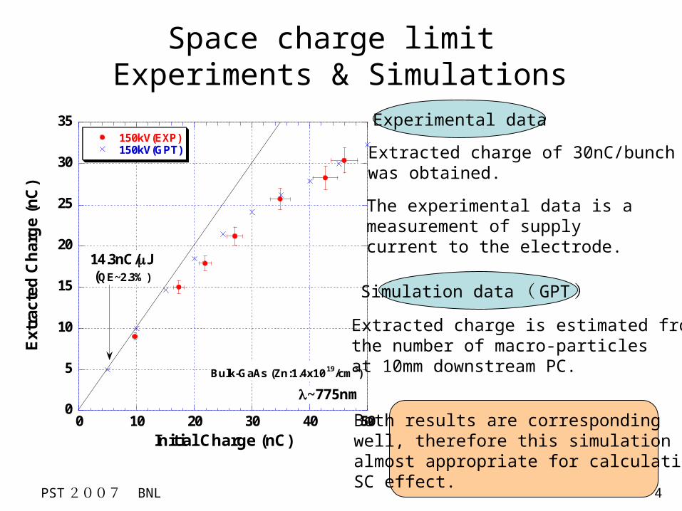
Extracted charge of 30nC/bunch was obtained.
0
5
10
15
20
25
30
35
0 10 20 30 40 50
150kV(EXP)150kV(GPT)
Ext
ract
ed C
har
ge
(n
C)
Initial Charge (nC)
~775nm
Bulk-GaAs (Zn:1.4x10¹⁹/cm3)
14.3nC/J(QE~2.3%)
Space charge limit Experiments & Simulations
The experimental data is a measurement of supply current to the electrode.
Both results are corresponding well, therefore this simulation is almost appropriate for calculatingSC effect.
Experimental data
Simulation data( GPT)
Extracted charge is estimated from the number of macro-particlesat 10mm downstream PC.

PST2007 BNL 5
Higher voltage gun operation is better for generating short and low emittance bunches, but operation risks (dark current, breakdown) become higher…
These simulations have been donein a situation of the beam emittance minimized at 0.5m downstream fromPC by using a solenoid.
Small beam radius helps suppressing emittance growth while bunching in the SHBs section.
Beam simulations at gun exit (before SHBs)
The emittance and beam radius become smaller .
z=0.5m
1ns bunch length
Advantages of higher voltage
Beam loss at injector region become lower.

PST2007 BNL 6
R 24
R 15
cathode
anode
flat top
:mm
gap
0
200
400
600
800
1000
1200
1400
0 50 100 150
DA
RK
CU
RR
EE
NT
[pA
]
FI ELD GRADI ENT [MV/ m]
SUS42MV/m
Cu50MV/m
Ti103MV/m
Mo115MV/m
Ti-Mo130MV/m
Gap 0.5mm results
Material dependence of dark current
Electrode shape
F.Furuta et al., NIM-A 538 (2005) 33-44
Nagoya & KEK
Test sample

PST2007 BNL 7
Reduction of primary field emissions
Reduction of secondary enhanced emissions
Mo
Ti
e-
+
e-
Cathode
Anode
-
Primary field emission
Dark current =
Enhanced emission+
F-N theory
Ions emission from the anode, secondary electrons and negative ions emission from the cathode.
Material dependence of dark current
wisker
Enhanced emission current

PST2007 BNL 8
Fabricating process of Mo Cathode
Hot squeezing
EB weldingAnnealing 400 1h℃Electro-buff polishing
Pure Mo (99.96%) sheets2mm thickness
e beam
rotation

PST2007 BNL 9
Installation & Vacuum test
Pure Titanium > 99.6%Finishing: Electro-buff polish
Ti-anode
Base pressure : 2.7x10⁻⁹ Pa
no vacuum problem
PST2007 BNL 10
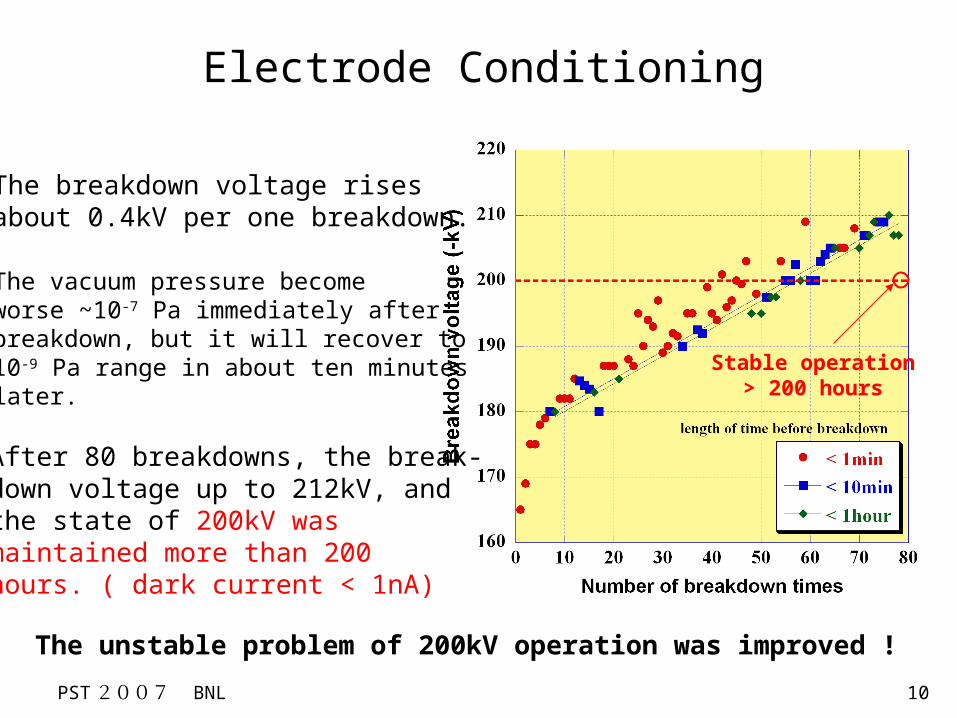
Electrode Conditioning
After 80 breakdowns, the break-down voltage up to 212kV, andthe state of 200kV was maintained more than 200 hours. ( dark current < 1nA)
The breakdown voltage rises about 0.4kV per one breakdown.
The unstable problem of 200kV operation was improved !
The vacuum pressure become worse ~10-7 Pa immediately afterbreakdown, but it will recover to 10-9 Pa range in about ten minutes later.
Stable operation> 200 hours

PST2007 BNL 11
Characteristics of SUS and Ti-Mo electrode
Dark current characteristic isn’t degraded even if many breakdowns were occurred.
Hardly observed dark current until breakdown was occurred.
0
2
4
6
8
10
100 120 140 160 180 200 220
Dar
k c
urr
en
t [n
A]
Voltage [-kV]
SUS electrode
0
0.2
0.4
0.6
0.8
1
100 120 140 160 180 200 220
Dar
k C
urr
ent
[nA
]
Voltage [-kV]
Ti anode & Mo cathode
Breakdown
Breakdown
Breakdown
Advantages of Ti-Mo electrode

PST2007 BNL 12
0
50
100
150
200
250
300
350
0 5 10 15 20 25
Beam Current (nA)F.C.(nA)
Cu
rre
nt
(nA
)
Time(hour)
Bulk GaAs, He-Ne 633nm, 200kV
Vacuum:4.0x10 -9Pa @Gun
6.1x10⁻⁹Pa @2-NEG.Cham.
Trans. 85~88%
Photocathode Lifetime
Preliminary
The photocathode lifetime seems no problem under the condition of a few micro amps beam emission.
Gun:2.7x10⁻⁹Pa2NEG:2.0x10⁻⁹Pa

PST2007 BNL 13
Summary
A large size and a light molybdenum electrode were made by the hot-squeezing and the EB welding.
Long-term 200keV operation became possible by employing the titanium anode and molybdenum cathode electrode.
The dark current characteristic of the electrode hardly degrades by breakdowns. A higher voltage (>200kV) operation would be possible by continuing additional conditionings.