psi (photon systems instruments), spol. s r.o. · pdf filedicotyledonous plants as small as...
TRANSCRIPT
PSI (Photon Systems Instruments), spol. s r.o.
Koláčkova 39, 621 00 Brno
Pobočka :Drásov 470, 664 24
tel. : +420 511 440 011
DIČ: CZ60646594
www.psi.cz

Page 2
PSI (Photon Systems Instruments), spol. s r.o.
Koláčkova 39, 621 00 Brno
Pobočka :Drásov 470, 664 24
tel. : +420 511 440 011
DIČ: CZ60646594
www.psi.cz
CONTENTS Introduction 4 PlantScreen High Throughput Phenomics Screening 5 Acclimatization Chamber 5 Chlorophyll Fluorescence Measurements 6 RGB and Morphometric Analysis 8 Thermal Imaging 12 Hyperspetral Imaging 13 Near Infra Red (NIR) Imaging 16 Weighing, Irrigation and Nutrient Delivery 16 Identification of Samples 17 Environmental Control in the Cabinet 18 Graphical Control Software 19 Schematic Representation of PlantScreen 23 Data Base Software 24 PlantScreen Detailed Technical Specifications 36 Transport System 36 Control System 44 Measuring Stations 45 Weighing and Watering 46 RGB Imaging Station 52 Lights 58 Hyperspectral Imaging 58 Fluorescence Imaging 61 Thermal Imaging 64 Environmental Measurements 64 Spraying 65 Installation Requirements 67 Informatics System 67 Data Base Computer 71 Data Base Structure 73 Future Expansion, Services, Safety and Support 74

Page 3
PSI (Photon Systems Instruments), spol. s r.o.
Koláčkova 39, 621 00 Brno
Pobočka :Drásov 470, 664 24
tel. : +420 511 440 011
DIČ: CZ60646594
www.psi.cz
CONTENTS (cont.) Controlled Cultivation Environments for Plant Phenomics Screening 75 Dimensions 75 Insulation 76 Temperature and Energy Loss Control 77 Cooling, Air Supply, Pressure Losses 80 Lighting Systems 81 Grain Growth under LED Lights 84 Humidification System 86 Air Filtration 87 Management Software, Data Acquisition and Storage 88

Page 4
PSI (Photon Systems Instruments), spol. s r.o.
Koláčkova 39, 621 00 Brno
Pobočka :Drásov 470, 664 24
tel. : +420 511 440 011
DIČ: CZ60646594
www.psi.cz
Systems and Technologies for Growth and Phenotypic Monitoring of Plants
For over years ten the Photon Systems Instruments (PSI) Company based in the Czech Republic has
developed numerous imaging systems to investigate the growth, physiology and response to
environment of plants. These imaging systems have been used in the laboratory, greenhouse, growth
room and the field. Dicotyledonous plants as small as Arabidopsis seedlings, and monocotyledonous
plants as large as mature corn plants, have been studied using these systems.
Qubit’s imaging systems are modular, and may include stations for:
RGB and Morphometric Imaging
Chlorophyll fluorescence Kinetic Imaging
Near InfraRed (NIR) Imaging
Hypespectral Imaging
Thermal Imaging
Automated Watering and Weighing
Automated Nutrient Delivery and Analysis
Automated Light Acclimation of Plants
In addition, PSI have developed conveyor-based technologies for the movement of plants from their
growth environment to the imaging apparatus. In situations in which it is preferred that the plants are
not moved, robotic crane systems have been designed and built to bring the imaging stations to the
plants. Novel systems have been designed for field-grown plants that use rails or motorized vehicles to
move the imaging system from plant to plant in a growth plot or across a field transect. These field
systems have been developed for plants varying from turf grass to tomatoes.
Clients include, among many others:
The International Rice Research Institute, Los Banos Philippines
The CSIRO Plant Phenomics Center, Canberra, Australia
The Australian National University, Canberra. Australia
Monsanto Corporation, St. Louis, USA.
Pioneer-Dupont, Des Moines, Iowa
Metanomics (BASF), Berlin, GDR
CropDesign (BASF), Nevele, Belgium
Synthetic Genomics, La Jolla, USA

Page 5
PSI (Photon Systems Instruments), spol. s r.o.
Koláčkova 39, 621 00 Brno
Pobočka :Drásov 470, 664 24
tel. : +420 511 440 011
DIČ: CZ60646594
www.psi.cz
All of PSI’s plant phenomic screening systems feature similar technology. This information document
provides the background to the technologies that may be configured in numerous ways for lab, field and
even aquatic screening systems.
PlantScreen Phenotyping System for High Throughput Screening with Acclimatization
Chamber and Conveyor
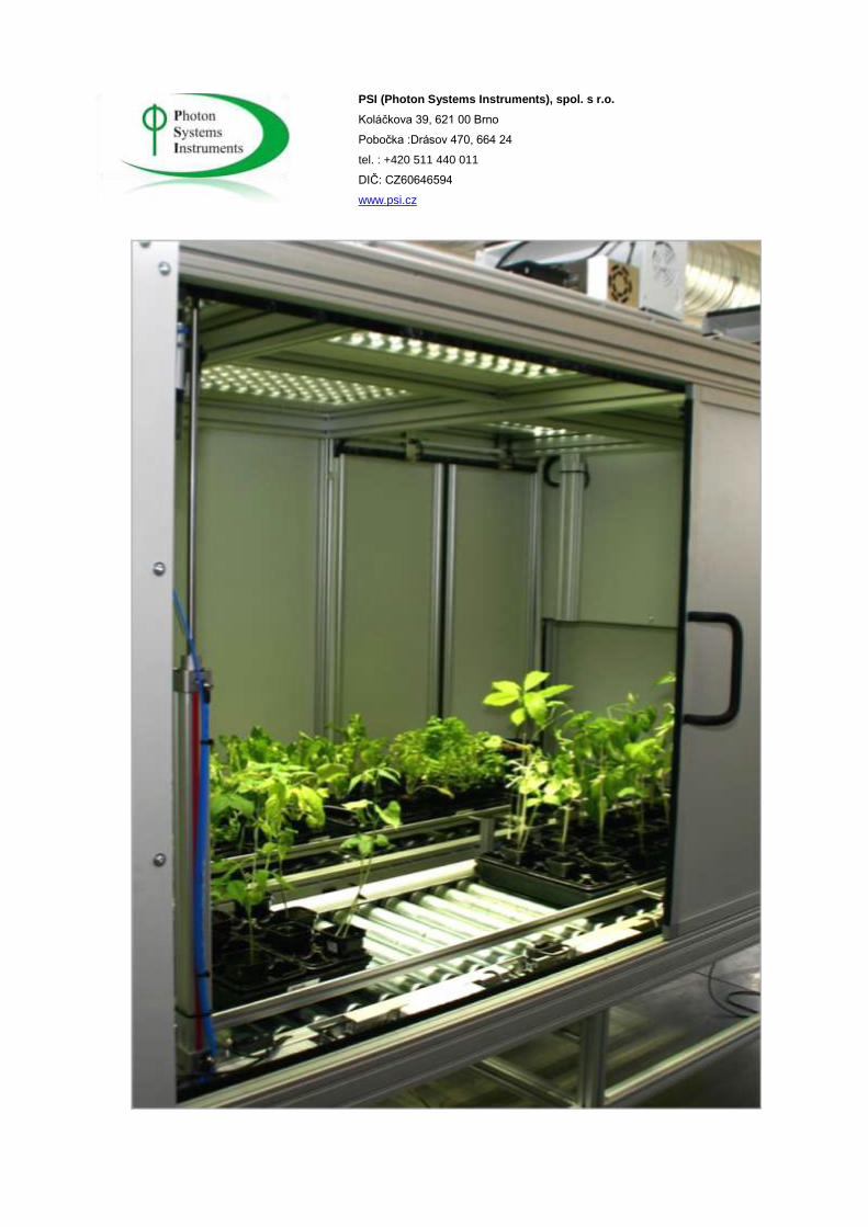
PSI’s high-throughput plant screening system (PlantScreen) allows the user to monitor numerous
aspects of plant growth, development and response to biotic and abiotic stresses. PlantScreen systems
can be designed and configured to meet the users’ specific requirements with respect to the size and
number of plants screened, as well as the environmental conditions to which they are exposed. In the
standard design, the samples are placed on trays with dimensions of 293x357 mm, and the maximum
height of the plant is 0.7 m. The maximum capacity of the PlantScreen in the standard configuration is
16 trays. A matrix of pots can be placed in each tray, or single larger plants in separate pots may be
screened. A typical pots used in the trays (20 per tray) has a volume of 200 ml and dimension of 7x7x9
cm (W x D x H).
The PlantScreen incorporates a number of instruments for imaging plant morphometric and
physiological parameters, as an acclimatization chamber that may be used to equilibrate plants under
controlled conditions, or even for plant cultivation.
Acclimatization Chamber
The PlantScreen includes an acclimation chamber for light/dark adaptation of samples. Light levels
provided by LED panels can be set with an irradiance of up to 1000mol m-2s-1 at the surface of the
plant. Lighting can be regulated from 0 to 100% of maximum. Software protocols may be used to
predefine the time and intensity of irradiance conditions.

Page 6
PSI (Photon Systems Instruments), spol. s r.o.
Koláčkova 39, 621 00 Brno
Pobočka :Drásov 470, 664 24
tel. : +420 511 440 011
DIČ: CZ60646594
www.psi.cz
Chlorophyll Fluorescence Measurements
The PlantScreen conducts chlorophyll fluorescence kinetics measurements on single plants or plant in
trays. When using trays, the measured data can be sorted automatically for each single sample on the
tray. The system performs automatic analysis of measured data, allows for visual display and stores both
numeric and image data.
Measured parameters: FO, FM, FV, FO', FM', FV', FT
Calculated parameters: FV/FM, FV'/FM', PhiPSII , NPQ, qN, qP, Rfd

Page 7
PSI (Photon Systems Instruments), spol. s r.o.
Koláčkova 39, 621 00 Brno
Pobočka :Drásov 470, 664 24
tel. : +420 511 440 011
DIČ: CZ60646594
www.psi.cz
Applications:
Screening for photosynthetic performance. Stress resistance or susceptibility. Stomatal patchiness. Metabolic perturbations. Growth and yield. • RGB digital growth analysis from 3 camera views, including thresholding and color analysis.
Software allows batch analysis of images for fluorescence quenching parameters including user-
identified regions of interest and averaging of pixel values on background subtracted images. Analyzed
data are stored in the database with co-registration of raw image data and analyzed data.

Page 8
PSI (Photon Systems Instruments), spol. s r.o.
Koláčkova 39, 621 00 Brno
Pobočka :Drásov 470, 664 24
tel. : +420 511 440 011
DIČ: CZ60646594
www.psi.cz
RGB Structural Imaging
RGB images are scanned with a resolution of 5 Mpx from three directions (from the sides and from the
top). Samples are illuminated with consistent quantity and quality of light. Options are available for the
inclusion of novel 3D scanning technology for the most in depth morphometric reconstruction of plants.
Image Processing
Step 1: Barrel distortion correction Step 2: Tray detection and cropping Step 3: Background subtraction
Results: Binary and RGB images as input for analysis
A B
C D
A: Barrel distortion correction B: Tray detection and cropping C: Background subtraction D: Binary and RGB Images

Page 9
PSI (Photon Systems Instruments), spol. s r.o.
Koláčkova 39, 621 00 Brno
Pobočka :Drásov 470, 664 24
tel. : +420 511 440 011
DIČ: CZ60646594
www.psi.cz
Parameters Computed:
Leaf Area: Number of pixels covered by the plant surface converted to relevant units. Useful for monitoring growth rate.
Solidity/Compactness. Ratio between the area covered by the plant’s convex hull and the area covered by the actual plant.
Leaf Perimeter: Particularly useful for the basic leaf shape and width evaluation (combined with leaf area).
Eccentricity: Plant shape estimation, scalar number, eccentricity of the ellipse with same second moments as the plant (0…circle, 1…line segment).
Roundness: Based on evaluating the ratio between leaf area and perimeter. Gives information about leaf roundness.
Medium Leaf Width Index: Leaf area proportional to the plant skeleton (i.e. reduction of the leaf to line segment).
Circle Diameter. Diameter of a circle with the same area as the plant.
Convex Hull Area. Useful for compactness evaluation
Centroid. Center of the plant mass position (particularly useful for the eccentricity evaluation)
Internodal Distances
Growth Height
Maximum Height and Width of Plant in 3 Dimensions
Leaf Angle
Leaf Number at Nodes

Page 10
PSI (Photon Systems Instruments), spol. s r.o.
Koláčkova 39, 621 00 Brno
Pobočka :Drásov 470, 664 24
tel. : +420 511 440 011
DIČ: CZ60646594
www.psi.cz
Parameter Validation
Parameter measurements have been successfully validated using model objects with known shape and dimensions:

Page 11
PSI (Photon Systems Instruments), spol. s r.o.
Koláčkova 39, 621 00 Brno
Pobočka :Drásov 470, 664 24
tel. : +420 511 440 011
DIČ: CZ60646594
www.psi.cz
Validation Data with Real Plants
Other Measured Parameters
Color segmentation for plant fitness evaluation Sequentially computed relative leaf growth rates Comparison of leaf area differences during whole experiment Flattening index Circadian leaf area differences Greening index Contribution of individual colors after color segmentation and characterization:

Page 12
PSI (Photon Systems Instruments), spol. s r.o.
Koláčkova 39, 621 00 Brno
Pobočka :Drásov 470, 664 24
tel. : +420 511 440 011
DIČ: CZ60646594
www.psi.cz
Healthy Green Dark Green Light Green Other Color – for incidental stains
Thermal Imaging
To study heating of the samples during irradiation by light. Variations in mechanisms for self-cooling t
may allow certain plants to withstand periods of high irradiance and low water availability.
Resolution of 640x480 pixels
Temperature range from 20 to +120°C
Thermal sensitivity /NETD < 0.05°C at +30°C / 50 mK
Spectral range: Uncooled microbolometer with a range of 7.5-13 micrometers.
16 bit resolution of images.
Controlled thermal environment with LED light panel for illumination of samples with adjustable
intensity of illumination from 0 to 500mol m-2s-1 in increments of 1% and range from 0 to 100%.
Type of camera: FLIR SC645
The camera is fixed in the PlantScreen and cannot be moved between other devices.

Page 13
PSI (Photon Systems Instruments), spol. s r.o.
Koláčkova 39, 621 00 Brno
Pobočka :Drásov 470, 664 24
tel. : +420 511 440 011
DIČ: CZ60646594
www.psi.cz
Hyperspectral Imaging
Hyperspectral imaging has been used for many years to study patterns of plant growth from satellite imaging.This technology has been refined in PSI’s PlantScreen to provide hyperspectral image analysis of plants on a pixel by pixel basis.
Typical Reflectance Spectrum of a Leaf
NNIIRR
red edge (680-760)
400 450 500 600 700 Wavelength, nm
530 - 570 nm
NIR Blue
Green
Red

Page 14
PSI (Photon Systems Instruments), spol. s r.o.
Koláčkova 39, 621 00 Brno
Pobočka :Drásov 470, 664 24
tel. : +420 511 440 011
DIČ: CZ60646594
www.psi.cz
Using a Headwall hyperspectral camera with image analysis software, plant reflective indices can be visualized across the entire surface of the imaged sample(s). These indices may be correlated with numerous physiological conditions, as well as the status of the plant or leaf with respect to content of chlorophyll, accessory pigments, nitrogen etc. Examples of published Reflective Indices, all measurable with the PlantScreen Hyperspectral station are as follows:
Normalized Difference Vegetation Index (NDVI) Reference: Rouse et al. (1974) Equation: NDVI = (RNIR - RRED ) / (RNIR + RRED )
Simple Ratio Index (SR) Reference: Jordan (1969); Rouse et al. (1974) Equation: SR = RNIR / RRED
Modified Chlorophyll Absorption in Reflectance Index (MCARI1) Reference: Haboudane et al. (2004) Equation: MCARI1 = 1.2 * [2.5 * (R790- R670) - 1.3 * (R790- R550)]
Optimized Soil-Adjusted Vegetation Index (OSAVI) Reference: Rondeaux et al. (1996) ) Equation: OSAVI = (1 + 0.16) * (R790- R670) / (R790- R670 + 0.16)
Greenness Index (G) Equation: G = R554 / R677
Modified Chlorophyll Absorption in Reflectance Index (MCARI) Reference: Daughtry et al. (2000) Equation: MCARI = [(R700- R670) - 0.2 * (R700- R550)] * (R700/ R670)
Transformed CAR Index (TCARI) Reference: Haboudane et al. (2002) Equation: TSARI = 3 * [(R700- R670) - 0.2 * (R700- R550) * (R700/ R670)]
Triangular Vegetation Index (TVI) Reference: Broge and Leblanc (2000) Equation: TVI = 0.5 * [120 * (R750- R550) - 200 * (R670- R550)]
Zarco-Tejada & Miller Index (ZMI) Reference: Zarco-Tejada et al. (2001) Equation: ZMI = R750 / R710
Simple Ratio Pigment Index (SRPI) Reference: Peñuelas et al. (1995) Equation: SRPI = R430 / R680
Normalized Phaeophytinization Index (NPQI) Reference: Barnes et al. (1992) Equation: NPQI = (R415- R435) / (R415+ R435)
Photochemical Reflectance Index (PRI) Reference: Gamon et al. (1992) Equation: PRI = (R531- R570) / (R531+ R570)
Normalized Pigment Chlorophyll Index (NPCI) Reference: Peñuelas et al. (1994) Equation: NPCI = (R680- R430) / (R680+ R430)

Page 15
PSI (Photon Systems Instruments), spol. s r.o.
Koláčkova 39, 621 00 Brno
Pobočka :Drásov 470, 664 24
tel. : +420 511 440 011
DIČ: CZ60646594
www.psi.cz
Carter Indices Reference: Carter (1994), Carter et al. (1996) Equation: Ctr1 = R695 / R420; Ctr2 = R695 / R760
Lichtenthaler Indices Reference: Lichtenthaler et al. (1996) Equation: Lic1 = (R790 - R680) / (R790 + R680); Lic2 = R440 / R690
Structure Intensive Pigment Index (SIPI) Reference: Peñuelas et al. (1995) Equation: SIPI = (R790- R450) / (R790+ R650)
Gitelson and Merzlyak Indices Reference: Gitelson & Merzlyak (1997) Equation: GM1 = R750/ R550; GM2 = R750/ R700)

Page 16
PSI (Photon Systems Instruments), spol. s r.o.
Koláčkova 39, 621 00 Brno
Pobočka :Drásov 470, 664 24
tel. : +420 511 440 011
DIČ: CZ60646594
www.psi.cz
The Plant Screen hyperspectral imaging station allows the user to acquire a full spectral scan across the entire spectral range of the camera for each pixel of the image. Alternatively, the user may select specific wavelengths of interest to record reflective indices that may be correlated with, for example, leaf nitrogen status, or the production of anthocyanin to protect Photosystem II under high light stress. It is also possible, in software, to establish patterns within hyperspectral measurements that are indicative of abiotic and biotic stresses, so that novel protocols for automated stress screening may be established.
Near Infra-Red (NIR) Imaging
The PlantScreen system may be configured with an imaging station specific for monitoring and comparing the water status of plants, or for assessing variations of the water status within different plant tissues. In this station the camera is set to collect data in the absorbance band for water between 1450 and 1600 nm. Plants that are adequately hydrated show high absorbance of NIR light in this absorbance band (and low reflectance), whereas those subject to drying will show greater reflectance in this band. Applying a false color palette to the images allows the researcher to quickly identify plants that are drying rapidy compared to those that are maintaining a healthier water status. In this respect, the NIR imaging station is important when studying responses to drought stress and screening for plants with enhanced water use efficiency. Software allows individual plants to be tracked through an imposed drought cycle so that the time-course of the onset of drought stress, and response to re-watering, can be monitored. In addition, morphometric parameters, and measurements of photochemical effciency, may be correlated with stress and recovery events.

Page 17
PSI (Photon Systems Instruments), spol. s r.o.
Koláčkova 39, 621 00 Brno
Pobočka :Drásov 470, 664 24
tel. : +420 511 440 011
DIČ: CZ60646594
www.psi.cz
Weighing, Irrigation and Nutrient Delivery
The PlantScreen system is able to weigh individual samples placed in trays or in individual pots. When using standard trays, 5 pots are lifted from the tray simultaneously, and the weights recorded with an accuracy of ± 2g. After weighing, each sample can be irrigated to a desired weight. Software protocols allow the user to specify a watering regime for the provision of adequate water, or for the time-dependent imposition of drought stress.
Watering and Weighing Station
Water may be supplied by gravity from a tank or the system may be configured to deliver both water
and nutrients from a nutrient supply system with an option for nutrient analysis.
Identification of Samples
Individual trays are identified by a barcode that is read automatically by the system. This allows
automated selection of samples from the growth chamber or greenhouse for screening. The data
obtained from individual measurements are uniquely assigned to the samples on the basis of their ID
and the measurement time. RFID devices may be used as an alternative, or additional, method for
tracking trays, pots and individual samples.

Page 18
PSI (Photon Systems Instruments), spol. s r.o.
Koláčkova 39, 621 00 Brno
Pobočka :Drásov 470, 664 24
tel. : +420 511 440 011
DIČ: CZ60646594
www.psi.cz
Environmental Control in the Imaging Cabinet
The PlantScreen imaging components are housed in a cabinet that equilibrates plants to user-defined
environmental conditions prior to screening. This is critically important when imaging chlorophyll
fluorescence kinetics, since data are dependent on irradiance conditions e.g. dark pre-adaptation,
Kautsky induction, light-adapted quantum yield etc. Controlled irradiance conditions are also critical to
success thermal imaging, since variations in heat load or heterogeneity can render sensible analysis of
images virtually impossible.
The entire upper surface of the interior of the PlantScreen is covered with LED panels that can deliver
irradiance levels in excess of 1000 umol photons/m2/s at the plant surface. Irradiance can be controlled
between 0 and 100% of maximum in 1% increments, and automated lighting protocols may be
programmed in software. The LEDs are collimated to ensure that irradiance is homogeneous in a plane
at any distance from the panels. Light quality may be varied by selecting LEDs of different wavelengths
to create specific light environments.

Page 19
PSI (Photon Systems Instruments), spol. s r.o.
Koláčkova 39, 621 00 Brno
Pobočka :Drásov 470, 664 24
tel. : +420 511 440 011
DIČ: CZ60646594
www.psi.cz
Since LEDs have no warm-up period, their use allows instantaneous changes to be made in light quality
and quantity. Also, unlike traditional light sources, they create virtually no heat load on the plant. The
PlantScreen cabinet can, therefore, be maintained at fixed temperature without the need for cooling
fans that could disturb the plants during the imaging processes.
The PlantScreen cabinet may be used for plant cultivation, and can be built to accommodate a wide
variety and number of plants. Alternatively, plants may be delivered to the cabinet via a conveyor belt
from a growth facility.
Environmental conditions within the PlantScreen cabinet are monitored continuously in software. Since
the system only operates with the doors closed, cameras are placed strategically within the cabinet to
show plant position and movement, allowing the user to intervene should any unexpected event occur.
Graphical Control Software
PlantScreen data acquisition and control software allows the user to define measurement protocols,
and view the current status of the device. Pre-defined protocols are available that may be edited easily
by the user. These protocols carry out repeated sequences of measurements under defined
environmental conditions. All data are stored into a relational MySQL database, in which it is easy to
search data by selected parameters. The number of measurements that may be made depends on the
size of storage space. It is possible to record up to 1000 measurements on a 200 gigabytes storage
device.
Defining Protocols with PlantScan Client
PlantScan Client software controls and monitors the entire PlantScreen device via a touch screen
interface.

Page 20
PSI (Photon Systems Instruments), spol. s r.o.
Koláčkova 39, 621 00 Brno
Pobočka :Drásov 470, 664 24
tel. : +420 511 440 011
DIČ: CZ60646594
www.psi.cz
The touch screen is divided into several operational areas, including a schematic representation of the
entire device which displays the number of trays inserted into the PlantScreen, light levels and status of
individual measurement devices and their activity.

Page 21
PSI (Photon Systems Instruments), spol. s r.o.
Koláčkova 39, 621 00 Brno
Pobočka :Drásov 470, 664 24
tel. : +420 511 440 011
DIČ: CZ60646594
www.psi.cz
View of Online Operation of the PlantScreen using IP Cameras
Lighting in the cultivation (non-imaging) section of the chamber is divided into several sectors. In any
sector, it is possible to separately switch the lighting on or off and to set the desired irradiance level.

Page 22
PSI (Photon Systems Instruments), spol. s r.o.
Koláčkova 39, 621 00 Brno
Pobočka :Drásov 470, 664 24
tel. : +420 511 440 011
DIČ: CZ60646594
www.psi.cz
Control allows both manual setting of all parameters and a fully automatic mode that operates in
accordance with a predefined protocol. Thge automated mode may be over-ridden if required.
Imaging Station Controls
Operation of the RGB imaging station s is done in a separate software tab, each camera having its own
control panel. Here, the user can set the exposure time, gain, and balancing between different color
components.
The Take Snapshot button is used for instantaneous image capture. The image is displayed in the left
frame, together with details such as resolution, time of the scan, format, etc. The image can be saved

Page 23
PSI (Photon Systems Instruments), spol. s r.o.
Koláčkova 39, 621 00 Brno
Pobočka :Drásov 470, 664 24
tel. : +420 511 440 011
DIČ: CZ60646594
www.psi.cz
using the Save button. For high-quality images, it is possible to turn on illumination lighting using the -
On/Off button.In automatic mode, the PlantScreen software can be set so that images are automatically
recorded and saved into a database for subsequent processing. The system is designed so that lighting
conditions, and plant position with respect to cameras, are identical for each image. The IR camera is
operated in a similar similarly to the RGB camera, under a separate tab. Chlorophyll fluorescence
imaging and hyperspectral imaging have more complex control protocols.
Automated Operation
The PlantScreen is designed primarily for operation in automatic mode. The user may select a
predefined protocol from a Wizard, or enter individual operational steps that can be saved as anew
protocol:
Switching the lighting on / off in the cultivation area
Scanning using RGB cameras
Scanning using IR camera
Implementation of chlorophyll fluorescence measurements under their own
easurement protocol
Implementation of hyperspectral measurements under their own measurement
protocol
Weighing of individual samples
On the base of weighting, supply a specified level of irrigation
The chosen procedures are implemented with defined timing and repetition.

Page 24
PSI (Photon Systems Instruments), spol. s r.o.
Koláčkova 39, 621 00 Brno
Pobočka :Drásov 470, 664 24
tel. : +420 511 440 011
DIČ: CZ60646594
www.psi.cz
Protocols can be started and stopped using the Start button or Stop button. Protocols may be paused
using the Pause button. The user can save the developed measurement protocols onto the PlantScan
computer or a portable drive.
Page 25
PSI (Photon Systems Instruments), spol. s r.o.
Koláčkova 39, 621 00 Brno
Pobočka :Drásov 470, 664 24
tel. : +420 511 440 011
DIČ: CZ60646594
www.psi.cz
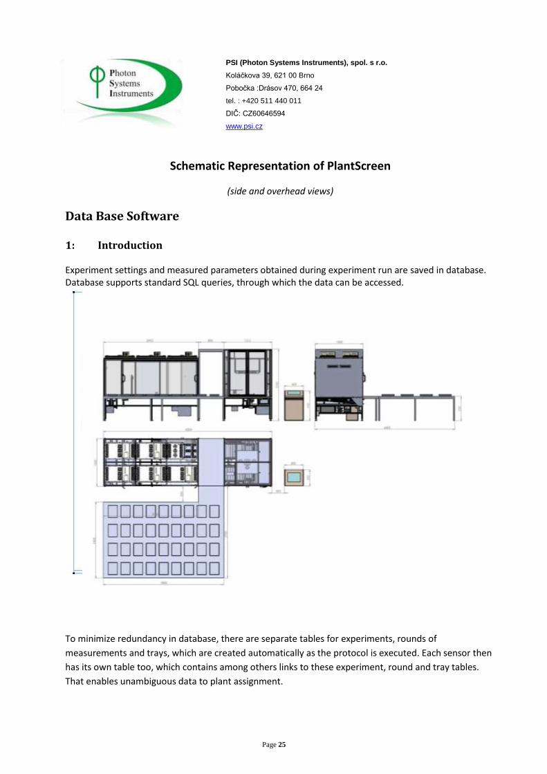
Schematic Representation of PlantScreen
(side and overhead views)
Data Base Software 1: Introduction Experiment settings and measured parameters obtained during experiment run are saved in database. Database supports standard SQL queries, through which the data can be accessed.
To minimize redundancy in database, there are separate tables for experiments, rounds of
measurements and trays, which are created automatically as the protocol is executed. Each sensor then
has its own table too, which contains among others links to these experiment, round and tray tables.
That enables unambiguous data to plant assignment.

Page 26
PSI (Photon Systems Instruments), spol. s r.o.
Koláčkova 39, 621 00 Brno
Pobočka :Drásov 470, 664 24
tel. : +420 511 440 011
DIČ: CZ60646594
www.psi.cz
To minimize redundancy in database, there are separate tables for experiments, rounds of
measurements and trays, which are created automatically as the protocol is executed. Each sensor then
has its own table too, which contains among others links to these experiment, round and tray tables.
That enables unambiguous data to plant assignment.
2. Basic Data Base Table Structure

Page 27
PSI (Photon Systems Instruments), spol. s r.o.
Koláčkova 39, 621 00 Brno
Pobočka :Drásov 470, 664 24
tel. : +420 511 440 011
DIČ: CZ60646594
www.psi.cz
Page 28
PSI (Photon Systems Instruments), spol. s r.o.
Koláčkova 39, 621 00 Brno
Pobočka :Drásov 470, 664 24
tel. : +420 511 440 011
DIČ: CZ60646594
www.psi.cz
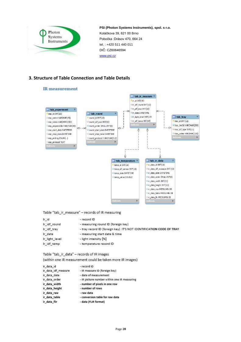
3. Structure of Table Connection and Table Details

Page 29
PSI (Photon Systems Instruments), spol. s r.o.
Koláčkova 39, 621 00 Brno
Pobočka :Drásov 470, 664 24
tel. : +420 511 440 011
DIČ: CZ60646594
www.psi.cz
4. FluorCam Measurement Data

Page 30
PSI (Photon Systems Instruments), spol. s r.o.
Koláčkova 39, 621 00 Brno
Pobočka :Drásov 470, 664 24
tel. : +420 511 440 011
DIČ: CZ60646594
www.psi.cz
5. RGB Data Base

Page 31
PSI (Photon Systems Instruments), spol. s r.o.
Koláčkova 39, 621 00 Brno
Pobočka :Drásov 470, 664 24
tel. : +420 511 440 011
DIČ: CZ60646594
www.psi.cz
6. Weighing Data Base
Page 32
PSI (Photon Systems Instruments), spol. s r.o.
Koláčkova 39, 621 00 Brno
Pobočka :Drásov 470, 664 24
tel. : +420 511 440 011
DIČ: CZ60646594
www.psi.cz
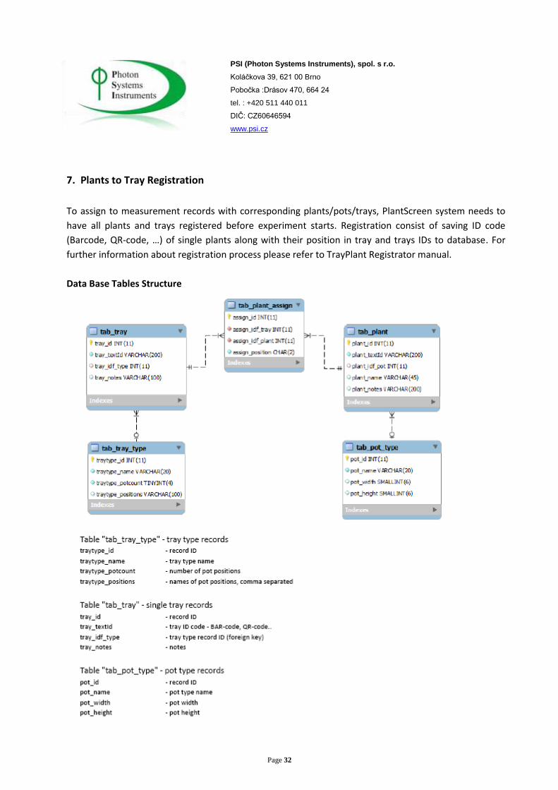
7. Plants to Tray Registration
To assign to measurement records with corresponding plants/pots/trays, PlantScreen system needs to
have all plants and trays registered before experiment starts. Registration consist of saving ID code
(Barcode, QR-code, …) of single plants along with their position in tray and trays IDs to database. For
further information about registration process please refer to TrayPlant Registrator manual.
Data Base Tables Structure

Page 33
PSI (Photon Systems Instruments), spol. s r.o.
Koláčkova 39, 621 00 Brno
Pobočka :Drásov 470, 664 24
tel. : +420 511 440 011
DIČ: CZ60646594
www.psi.cz

Page 34
PSI (Photon Systems Instruments), spol. s r.o.
Koláčkova 39, 621 00 Brno
Pobočka :Drásov 470, 664 24
tel. : +420 511 440 011
DIČ: CZ60646594
www.psi.cz
8. Example of SQL Queries

Page 35
PSI (Photon Systems Instruments), spol. s r.o.
Koláčkova 39, 621 00 Brno
Pobočka :Drásov 470, 664 24
tel. : +420 511 440 011
DIČ: CZ60646594
www.psi.cz
9. FluorCam Data

Page 36
PSI (Photon Systems Instruments), spol. s r.o.
Koláčkova 39, 621 00 Brno
Pobočka :Drásov 470, 664 24
tel. : +420 511 440 011
DIČ: CZ60646594
www.psi.cz
10. Plant Registration

Page 37
PSI (Photon Systems Instruments), spol. s r.o.
Koláčkova 39, 621 00 Brno
Pobočka :Drásov 470, 664 24
tel. : +420 511 440 011
DIČ: CZ60646594
www.psi.cz
PlantScreen Detailed Technical Specifications
TRANSPORT SYSTEM
Pot holder:
The holder can accommodate a pot with diameter of 21 cm at the top and 16 cm at the bottom. Its
height is 27 cm. The holder is made from non-toxic durable plastic material and is assembled from three
parts:
The bottom part is a plastic rectangular with dimension of 30 x 30 cm. It includes 4 RFID tags for
identification. Tags are attached to the bottom part; each side has one tag. There is a drain hole in the
center of the bottom part.
Middle part: There are plastic legs connecting the bottom and top parts. They allow sliding on
conveyer belt side bars.
The top part is made from blue plastic (marine blue). There is one hole with diameter of 21 cm.
The pot is to be positioned from the top.
The middle part contains only four legs so as to allow free air moving. Each pot has a bar code attached
on its side, which is very convenient for easy barcode reading.The holder construction, which is
assembled from three parts, allows cheap and flexible manufacture that can be easily adjusted
according to customer’s needs. We are able to cut plastic desk on our water jet cutter and big series can
be produced in cooperation with a sub-supplying company.
Only the bottom part has to have the same dimension for each pot. Length of legs can be modified to
use pots with different height and the top part can have a hole with different diameter. Maximum
diameter is 21 cm.
The adapter which changes the diameter of 21 cm to different sizes is inserted into holder. It is also
possible to build a tray with matrix for small pots where only the ground must be of 30 x 30 cm
dimension. The tray can accommodate 16 pots with volume of 200 ml each.
PSI has developed and produced its own trays for the PlantScreen high throughput system.
Used materials are stable in various light and temperature conditions; they are non-toxic and resistant
to abrasion. The use of 4 RFID tags allows using the holder in all positions and manipulation mistakes are
thus eliminated.

Page 38
PSI (Photon Systems Instruments), spol. s r.o.
Koláčkova 39, 621 00 Brno
Pobočka :Drásov 470, 664 24
tel. : +420 511 440 011
DIČ: CZ60646594
www.psi.cz
Figure 1: Pot holder

Page 39
PSI (Photon Systems Instruments), spol. s r.o.
Koláčkova 39, 621 00 Brno
Pobočka :Drásov 470, 664 24
tel. : +420 511 440 011
DIČ: CZ60646594
www.psi.cz
Figure 2: Holder picture
Transport System:
The transport system includes conveyor belt lines. There is a loop through the measuring part and two
lines for moving plants between the growing and measuring part. PSI cooperates with the following
specialist for conveyor systems and aluminum profile systems:
Haberkorn Ulmer s.r.o.
Generála Vlachého 305
747 62 Mokré Lazce
Czech Republic
http://www.haberkorn.cz/en
Habekorn Company builds constructions from German aluminum profile systems:
http://www.item24.be/

Page 40
PSI (Photon Systems Instruments), spol. s r.o.
Koláčkova 39, 621 00 Brno
Pobočka :Drásov 470, 664 24
tel. : +420 511 440 011
DIČ: CZ60646594
www.psi.cz
Belgium Partner:
PEC products n.v.
Technologielaan 12
3001 LeuvenTel.: +32 / 16 / 398 355
Fax.: +32 / 16 / 403 445
item(at)peccorp.com
www.pec.be
Motion components are supplied by the Raveomotion Company. The company produces and
distributes various components for motion, like motors, gearboxes and controllers for industrial
application.
http://www.raveo.cz/en/node/4
Motors and gear box are supplied from:
Conveyor belts use 3 phase asynchronous motors with a gearbox. Power range is 200 W – 1000 W
depending on position in transport system.
Gearbox for buffer is supplied by:
WORMGEARBOXES CM
Gear box for accuracy positioning (transport line, image line) is supplied by:
BEVEL HELICAL GEARBOXES CMB
Cultivation Cabinet
Totally 360 plants
Parallel lines 16
In one line 23 plants
Distance between centers of lines 720 mm

Page 41
PSI (Photon Systems Instruments), spol. s r.o.
Koláčkova 39, 621 00 Brno
Pobočka :Drásov 470, 664 24
tel. : +420 511 440 011
DIČ: CZ60646594
www.psi.cz
FIFO buffer (first in / first out)
Aseparate driver for each motor allows moving plants between lines independently on measuring
protocol.
Line width 320 mm
Line length 7500 mm
Free space for one plant 960 mm2
Load capacity for one line 130 kg
Motor 3 phase, 3x400V
Gear box 1:15
Speed 0,15 m.s-1 (9 m.min-1)
Figure 3: Situation Scheme
Conveyor crossing and curves:
Buffer and image lines are 80 cm high from ground to belt and have a simple construction: frame,
conveyor belt with motor, and gearbox. Each line has two sensors at the beginning and at the end.
Page 42
PSI (Photon Systems Instruments), spol. s r.o.
Koláčkova 39, 621 00 Brno
Pobočka :Drásov 470, 664 24
tel. : +420 511 440 011
DIČ: CZ60646594
www.psi.cz
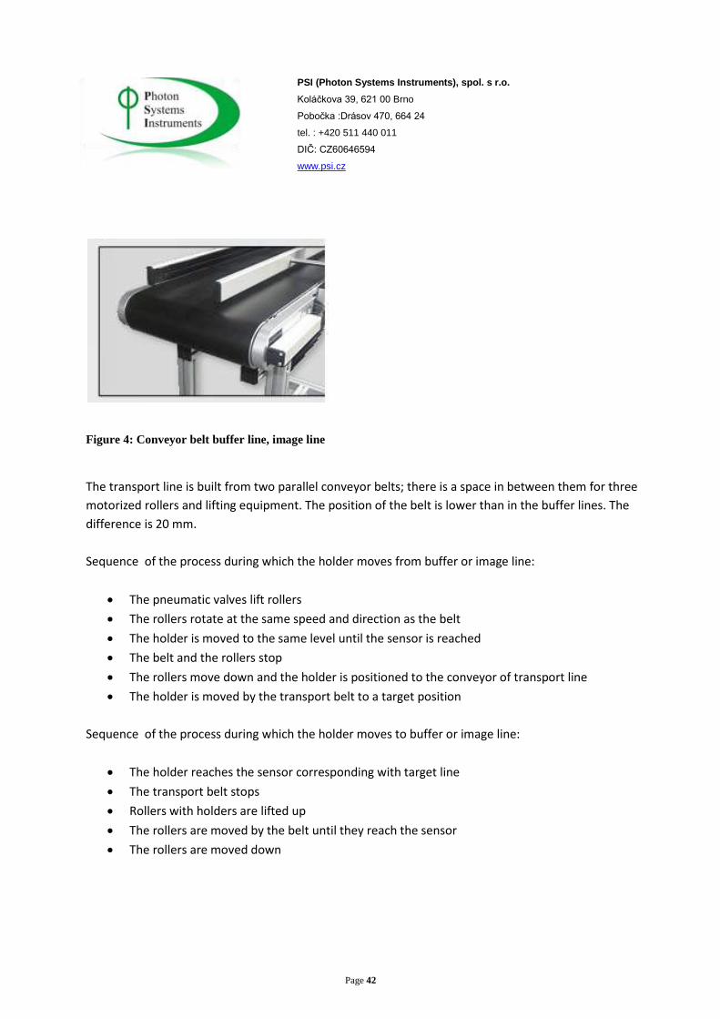
Figure 4: Conveyor belt buffer line, image line
The transport line is built from two parallel conveyor belts; there is a space in between them for three
motorized rollers and lifting equipment. The position of the belt is lower than in the buffer lines. The
difference is 20 mm.
Sequence of the process during which the holder moves from buffer or image line:
The pneumatic valves lift rollers
The rollers rotate at the same speed and direction as the belt
The holder is moved to the same level until the sensor is reached
The belt and the rollers stop
The rollers move down and the holder is positioned to the conveyor of transport line
The holder is moved by the transport belt to a target position
Sequence of the process during which the holder moves to buffer or image line:
The holder reaches the sensor corresponding with target line
The transport belt stops
Rollers with holders are lifted up
The rollers are moved by the belt until they reach the sensor
The rollers are moved down

Page 43
PSI (Photon Systems Instruments), spol. s r.o.
Koláčkova 39, 621 00 Brno
Pobočka :Drásov 470, 664 24
tel. : +420 511 440 011
DIČ: CZ60646594
www.psi.cz
Figure 5: Lines crossing, side view
Figure 6: Line crossing top view

Page 44
PSI (Photon Systems Instruments), spol. s r.o.
Koláčkova 39, 621 00 Brno
Pobočka :Drásov 470, 664 24
tel. : +420 511 440 011
DIČ: CZ60646594
www.psi.cz
The orientation of plants is maintained during movement. The conveyors need minimum space.
http://psi.cz/products/customized-fluorcams/conveyor-and-robotic-plantscreen-systems
Figure 7: Conveyor curve picture from PlantScreen
The installed controllers allow changing motors direction in buffer and transport line and so it is possible
to move plants between lines without moving through image station independently on running
protocol.

Page 45
PSI (Photon Systems Instruments), spol. s r.o.
Koláčkova 39, 621 00 Brno
Pobočka :Drásov 470, 664 24
tel. : +420 511 440 011
DIČ: CZ60646594
www.psi.cz
Control System:
Transport system and camera movement are controlled by central PLC:
Industrial components from OMRON are used in the system. Omron is a Japanese company.
The European headquarters and manufacture site is located in Netherlands.
OMRON Europe B.V. (OMCE/OEE-HQ)
Wegalaan 67-69 2132 JD HoofddorpThe Netherlands
TEL: 31-23-568-1400 FAX: 31-23-568-1388
European regional office
Components
Central processor unit CJ2M-CPU33
Digital I/O max 2 560 points
Program memory 20 k word
Data memory 64 k word
I/0 units max 40
Include USB+EtherNet/IP communication, free communication slot.
High accuracy positioning via OMRON MECHATROLINK-II max 16 axis
PLC communicates with supervisor PC via Ethernet 100Mb/s.
Extension modules: Digital Input
Digital Output transistor/relay
Analog Input/ Output 4-20 mA, 0-10V, -10 – 10 V
Temperature sensors Pt1000, Pt100, PTC
Position controller
Sensors:
System use optical sensors from Omron:
E3Z - universal optical sensor, Through beam
E3ZLS - diffuse reflectance (background suppression)
Pneumatic piston and pneumatic component made by Festo.
Sensors for pneumatic piston Festo.
Inductive and capacity sensors are used.

Page 46
PSI (Photon Systems Instruments), spol. s r.o.
Koláčkova 39, 621 00 Brno
Pobočka :Drásov 470, 664 24
tel. : +420 511 440 011
DIČ: CZ60646594
www.psi.cz
Measuring Station:
Measuring stations include three light-isolated measuring chambers. There are fast moving doors with
open close cycle < 3s on the input, output and in between the chambers.
Free space 1,5m x 1,5m (h x w).
A plant is moved on the conveyer belt to measuring position. Optical sensors indicate its correct
position.
Fluorescence/ Thermo imaging and hyperspectral box are very similar in their construction. The cabinet
contains a frame which can accommodate fixed cameras or a robotic system for scanning. The system
can hold different components for future enh
The RFID and barcode reader for identification of plant and light curtain are positioned at the beginning
of the image line.
The identification system uses a product from
http://www.automation.datalogic.com
RFID reader Cobalt HF
Reading distance 2 – 20 cm.
Communication via RS485.
Barcode reader: Matrix 210TM that allows reading 1D and 2D codes, QR code etc. It also
includes LED light for reading in poor light conditions. Communication is via RS485.
Light curtain OMRON F3EM2
Measuring range: 1500 mm
Resolution: 5 mm
The curtain measures the highest point, which is used for calculation of the proper camera position.
At the same time, the control program calculates the width of a plant (from the time that is taken by a
plant to proceed via the light curtain).
One light curtain brings information about two plant dimensions: height and width.

Page 47
PSI (Photon Systems Instruments), spol. s r.o.
Koláčkova 39, 621 00 Brno
Pobočka :Drásov 470, 664 24
tel. : +420 511 440 011
DIČ: CZ60646594
www.psi.cz
WEIGHING AND WATERING STATION
The station weigh holder with a single pot. Maximum load is 7 kg pot + plant + holder. All components
have at least IP 66 protection. The station has protection against splashing water, soil and dust. Weight
is saved to database. If watering is used, newly reached value is saved too. The system is capable of
automatic calibration of the zero point before measuring and also of recalibration by using a special
holder with accuracy known mass. This process is automatic. A user must put the holder to loading
space and choose calibration process in the supervising program. After the calibration process, new
constants are saved and ready to be used.
Weighing accuracy: 1 g for load in the range of 0 – 7 kg
Operation programmable in protocol:
Operation Description Time for Operation
Nothing Holders move through without stop 0 s
Weight Weight holder, information saved to Database 10 s
Watering Add defined amount of water to each pot Depend on amount, max 20
s
Weight and
watering
Weighing before watering, save to DB.
Adding to target value individual for each pot
or the same for all pots from the batch. Target
value can be modified in running experiment.
Calculation from actual mass.
Adding percentage from actual mass.
Depend on amount, max 25
s
Weighing station contains:
- Separately controlled conveyor belt with motor and position sensor
- 4 load cells
- Frame
- Communication with PLC and supervisor computer

Page 48
PSI (Photon Systems Instruments), spol. s r.o.
Koláčkova 39, 621 00 Brno
Pobočka :Drásov 470, 664 24
tel. : +420 511 440 011
DIČ: CZ60646594
www.psi.cz
The conveyor belt is mounted on four load cells, one in each corner. The belt can move independently
up and down in range of µm. If a plant reaches center position, the belt stops and measuring can start.
Each load cell is similar to UTILCELL®.
http://www.utilcell.cz/?page=product-detail&category=39&product=292
Figure 8: Utillcel Model 240
Load cell UTILCELL Model 240
Nominal capacity 5 kg
Accuracy class 4000 n.OIML
Minimum dead load 0 % Ln
Service load 120 % Ln
Safe load limit 150 % Ln
Total error <± 0,013 % Sn
Repeatability error <± 0,01 % Sn
Temperature effect on zero <± 0,01 % Sn/5K
Temperature effect on sensitivity <± 0,006 % Sn/5K
Creep error (30 minutes) <± 0,012 % Sn
Temperature compensation -10 …+40 °C
Temperature limits -20…+70 °C
Nominal sensitivity (Sn) 2 ± 10 %
Nominal input voltage 10 V

Page 49
PSI (Photon Systems Instruments), spol. s r.o.
Koláčkova 39, 621 00 Brno
Pobočka :Drásov 470, 664 24
tel. : +420 511 440 011
DIČ: CZ60646594
www.psi.cz
Maximum input voltage 15 V
Input impedance 400 ± 20 Ω
Output impedance 350 ± 3 Ω
No load output <± 2
Insulation resistance >5000 MΩ
Maximum deflection (at Ln) 0,2 – 0,4 mm
Protection IP 66
The station includes a separate control box with electronic components and Digital analog convertor for
load cells. D/A convertor is placed close to load cells so as to minimize cable length. Short cables reduce
noises on wire and measuring is more accurate. Signals from cells are converted and send to the main
PLC via RS485 Modbus RTU protocol.
Digital/Analog convertor DAT 400
The convertor is intended for industrial application and has a microprocessor with up to 6 sensors with 4
or 6 wire connections. It has two serial interfaces, analog output, 2/2 digital I/O and the ability of
mathematic functions.
http://www.utilcell.cz/?page=product-detail&product=429&category=40
Exciting supply 5 V
Current load 90 mA

Page 50
PSI (Photon Systems Instruments), spol. s r.o.
Koláčkova 39, 621 00 Brno
Pobočka :Drásov 470, 664 24
tel. : +420 511 440 011
DIČ: CZ60646594
www.psi.cz
Conversion response 50x/second
Sensibility 0,02 µV/div
Linearity < 0,01 %
Temperature effect < 0,001 % from range / °C
Convertor A/D 24 bits
Filter 0,5 – 25 Hz
Discernment 1x, 2x, 5x
Decimal point 0; 0,0 ; 0,000
Calibration method From PC or front keyboard
Power supply 24 VDC ± 15%
Output interface RS-232, RS-422, RS-485
Standard protocol Modbus RTU
Transmission speed 2400, 9600, 19200, 38400 baud
Figure 9: Weighing station side and bottom view

Page 51
PSI (Photon Systems Instruments), spol. s r.o.
Koláčkova 39, 621 00 Brno
Pobočka :Drásov 470, 664 24
tel. : +420 511 440 011
DIČ: CZ60646594
www.psi.cz
The watering station includes:
- Pipes on pneumatic arm
- Manually adjustable distance, height and angle between the pipes and steam
- Pneumatic piston
- Solenoid valves, float control unit, pipes
- Ready for automatic mixing station
All components are made from durable, non-toxic plastic material. Used valves are
RainRainBirdl 100-HV-F 24V 1" (flow regulation) or similar.
The watering station cooperates with the weighing station. The pneumatic arm moves nozzle
close to steam and electrically controlled solenoid valve puts accurate amount of water. The
amount of water is set via a programmable protocol.
If an empty holder is detected, by weight holder with mass lower than adjustable level, the
information is written to database. Watering is then blocked for this actual pot and the holder
is moved out.
If it is not possible to reach preset weight in standard time, error is signalized. Watering is
interrupted and actual weight with error is saved to database.
If higher mass then set is weight before watering information is written to database and
watering is blocked for actual pot and holder is moved out.
The position of nozzle can be set manually in two dimensions and angles. It is possible to set
height in the range of -10 to + 20 cm and distance from the center of the belt in the range -10
to 20 cm. Each leg can be positioned separately so it is possible to set distance and angle
between nozzle and stem. Front side of the frame close to the conveyor belt is protected by a
wall made of plastic material.
It is recommended to have a drain close to watering station. Emergency tank is placed under
the station with connection to drain. High water level is signalized. If water reaches to
emergency level, then watering is blocked.
Page 52
PSI (Photon Systems Instruments), spol. s r.o.
Koláčkova 39, 621 00 Brno
Pobočka :Drásov 470, 664 24
tel. : +420 511 440 011
DIČ: CZ60646594
www.psi.cz
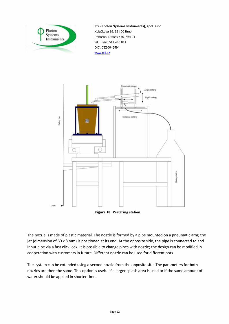
Figure 10: Watering station
The nozzle is made of plastic material. The nozzle is formed by a pipe mounted on a pneumatic arm; the
jet (dimension of 60 x 8 mm) is positioned at its end. At the opposite side, the pipe is connected to and
input pipe via a fast click lock. It is possible to change pipes with nozzle; the design can be modified in
cooperation with customers in future. Different nozzle can be used for different pots.
The system can be extended using a second nozzle from the opposite site. The parameters for both
nozzles are then the same. This option is useful if a larger splash area is used or if the same amount of
water should be applied in shorter time.

Page 53
PSI (Photon Systems Instruments), spol. s r.o.
Koláčkova 39, 621 00 Brno
Pobočka :Drásov 470, 664 24
tel. : +420 511 440 011
DIČ: CZ60646594
www.psi.cz
If very dry soil is manipulated and the difference between the actual and set value is too big, the
watering can be applied in cycles with pauses. In this case the water amount can be extended and more
time may be provided for soil to saturate water.
Variety of medium source:
Water line; requirements 3 bar pressure, flow rate 3L/min
Pumping from a barrel; requirements for pump: 3 bar pressure, flow rate 3L/min
Automatic mixing station; the station includes: barrel, pump, source of water, and liquid
medium.
If only water from line with pressure is used, no additional pumps are needed.
As an option, the system can use either the water line, or solution from barrel, or both possibilities.
Then more solenoid valves must be installed and a user can choose if watering only with water or with
added solution. The automatic mixing station includes all this components and possibilities.
RGB IMAGE STATION
Image station collects color picture in high resolution from three cameras from top, side and front. Data
are collected in a database; if the database is not accessible then they are saved to a local disc. Image
station is light isolated with its own light source. The system can measure plants with maximum
dimension 1,5 x 1,5 x 1,5 m (w, h, l).
PSI has developed its own software for RGB image processing and morphology analysis.
Morphological parameters:
- Leaf area
- Leaf perimeter
- Solidity / Compactness
- Eccentricity / Roundness
- Bounding box
- Equivalent circle diameter
- And many others
- Time for one scan <10 s

Page 54
PSI (Photon Systems Instruments), spol. s r.o.
Koláčkova 39, 621 00 Brno
Pobočka :Drásov 470, 664 24
tel. : +420 511 440 011
DIČ: CZ60646594
www.psi.cz
The system comprises of:
- Image box (light isolated)
- Conveyor belt and sensor indicating the pot in target position
- Three RGB cameras with lens
- Light sources
- Software for collecting, analyzing and representing measured data
Figure 11: RGB image station front view

Page 55
PSI (Photon Systems Instruments), spol. s r.o.
Koláčkova 39, 621 00 Brno
Pobočka :Drásov 470, 664 24
tel. : +420 511 440 011
DIČ: CZ60646594
www.psi.cz
Figure 12: RGB imaging station side view

Page 56
PSI (Photon Systems Instruments), spol. s r.o.
Koláčkova 39, 621 00 Brno
Pobočka :Drásov 470, 664 24
tel. : +420 511 440 011
DIČ: CZ60646594
www.psi.cz
Figure 13: RGB imaging station top view
Camera holders are universal, variety of cameras and lens can be mounted. Cameras have at least 10
Mpx resolution. The camera can be supplied with filters. It is possible to enhance the system and to
install in future cameras and lens with improved parameters. USB and Ethernet cameras can be supplied
on request. A user can opt for the camera and lens according to his preference.

Page 57
PSI (Photon Systems Instruments), spol. s r.o.
Koláčkova 39, 621 00 Brno
Pobočka :Drásov 470, 664 24
tel. : +420 511 440 011
DIČ: CZ60646594
www.psi.cz
We offer for example:
Camera: Lumenera corporation 10.7 Megapixel USB 2.0 Camera Lw 11059.
http://www.lumenera.com/products/industrial-cameras/lm11059.php
Image Sensor 43,3mm (diagonal), color 36,1 24,0 mm array
Effective Pixels 4008x2672, 9.0 µm square pixels
Frame Rate 5fps
Sensitivity Excellent
Exposure Manual & Auto
White Balance Manual & Auto
Dynamic Range 65 dB
Bits Resolution 12 bits
On-Board Memory 32 MB, 2 frames in full resolution
Dimension 3.25 x 2.98 x 5.59 inches
Mass 850 g
Communication USB 2.0
Lens Mount Canon-mount

Page 58
PSI (Photon Systems Instruments), spol. s r.o.
Koláčkova 39, 621 00 Brno
Pobočka :Drásov 470, 664 24
tel. : +420 511 440 011
DIČ: CZ60646594
www.psi.cz
Figure 14: Color response curve, source: Lw11059 datasheet, Lumenera cor.
Lens: Basically, depends on the type of camera and application. Different objectives with specified
parameters can be used. Installing a motorized lens is possible.

Page 59
PSI (Photon Systems Instruments), spol. s r.o.
Koláčkova 39, 621 00 Brno
Pobočka :Drásov 470, 664 24
tel. : +420 511 440 011
DIČ: CZ60646594
www.psi.cz
We offer for example:

Page 60
PSI (Photon Systems Instruments), spol. s r.o.
Koláčkova 39, 621 00 Brno
Pobočka :Drásov 470, 664 24
tel. : +420 511 440 011
DIČ: CZ60646594
www.psi.cz
Lights:
The light source is manufactured by the PSI and is mounted with white LEDs.
http://psi.cz/products/led-light-sources/led-light-source-sl-3500
Light parameters: cool white
Due to the dimension of the box and distance between the cameras and object, one camera is mounted
on linear guide. After a plant is in the requested position, the camera is moved down to proceed
measuring. After measuring is finished, the camera is moved up and the plant can move out of the
image box. The measured plant does not touch the camera objective; the objective is kept clear. Moving
up and down takes less than 2 s.
The conveyor belt is built from separate parts. As an option the central part can be changed for a
turning platform with a lift. The turning platform enables 3D reconstruction from images.
As an option, the image box can be supplied with an arm carrying cameras and 3D scanner, which is
turned around a plant. In this option, the plant is stable while the camera is moving. As the camera can
turn faster than the plant, the time required for one scan is shorter.
HYPERSPECTRAL IMAGING
The image station contains VNIR and SWIR camera with a light source. The camera with its light source
moves above plant and scans line by line the whole plant.
The system includes:
Light isolated measuring box
Automatic doors at each side (in and out)
Conveyor belt for plant transport into the measuring station
Automatic lifting system for camera focus (controlled from central PLC)
Light source
SWIR and VNIR camera
PC with measuring and analysis software

Page 61
PSI (Photon Systems Instruments), spol. s r.o.
Koláčkova 39, 621 00 Brno
Pobočka :Drásov 470, 664 24
tel. : +420 511 440 011
DIČ: CZ60646594
www.psi.cz
Linear guide with motor mounted in the lifting frame
VNIR camera:
HEADWALL PHOTONIC Hyperspec® VNIR
Wavelength Range 380 – 1000 nm
Aperture F/0.2
Dispersion per pixel 0.98 nm
Slit Width 25 µm
Slit Length 18 mm
Spectral Bands 675
Spatial Bands 1004
Detector Silicon
Dynamic Range 64 dB
Frame Rates (fps) 12-236
Pixel Pitch (microns) 8.0
Read A/D 14 bits
Binning Yes
Communication USB 2.0
Weight 3.4 kg
SWIR Camera:
HEADWALL PHOTONIC Hyperspec SWIR®
Wavelength Range 900 – 2500 nm
Aperture F/0.2
Dispersion per pixel 0.75 nm
Slit Width 25 µm
Slit Length 18 mm
Spectral Bands 200

Page 62
PSI (Photon Systems Instruments), spol. s r.o.
Koláčkova 39, 621 00 Brno
Pobočka :Drásov 470, 664 24
tel. : +420 511 440 011
DIČ: CZ60646594
www.psi.cz
Spatial Bands 320
Detector MCT
Dynamic Range 64 dB
Frame Rates (fps) 60 or 100
Pixel Pitch (microns) 30
Read A/D 14 bits
Binning No
Communication USB 2.0/CameraLink™
Weight 3.4 kg
The broadband light source is made by the PSI. The Light source is positioned in between the cameras.
When a plant reaches measuring position, the situation is indicated by a sensor. Both doors are then
closed and the frame with the camera moves to proper focusing position. The plant is scanned by the
VNIR camera in one direction and then by the SWIR camera in an opposite direction.
The chamber contains space for calibration lane for automatic calibration.
A user can choose protocols measuring with one of SWIR, VNIR or with both cameras.
Time for measuring:
VNIR camera use only: 15 s
SWIR camera use only: 15 s
Protocol in which both cameras are used: 30 s

Page 63
PSI (Photon Systems Instruments), spol. s r.o.
Koláčkova 39, 621 00 Brno
Pobočka :Drásov 470, 664 24
tel. : +420 511 440 011
DIČ: CZ60646594
www.psi.cz
Figure 15: Hyperspectral box front view Figure 16: Hyperspectral box side view

Page 64
PSI (Photon Systems Instruments), spol. s r.o.
Koláčkova 39, 621 00 Brno
Pobočka :Drásov 470, 664 24
tel. : +420 511 440 011
DIČ: CZ60646594
www.psi.cz
Figure 17: Hyperspectral box top view
FLUORESCENCE IMAGING
Fluorescence imaging is offered as an option. It uses the same box and equipment likas in e the thermal
imaging station. In one time, it is possible use only one measuring system.
Measuring process: A plant is moved on the conveyor belt to target position. Light panel with the
camera can move up and down to the position calculated from the plant height and focal length.
Fluorescence measuring uses modification of the FluorCam FC-800MF manufactured by the PSI
http://www.psi.cz/download/document/manuals/fluorcam-closed/FluorCam_Operation_Manual.pdf
The system includes:
Light-isolated measuring box
Automatic doors at each side (in and out)
Conveyor belt for plant transportation into the measuring space

Page 65
PSI (Photon Systems Instruments), spol. s r.o.
Koláčkova 39, 621 00 Brno
Pobočka :Drásov 470, 664 24
tel. : +420 511 440 011
DIČ: CZ60646594
www.psi.cz
Automatic lifting system for camera focusing (connected with PLC control system)
Light source
8 position filter wheel included in the camera
PC with measuring and analysis software
Light panel dimension is 1800 x 1800 mm (w x l), the area of light homogeneity is 1500 x 1500 mm. Light
intensity can reach up to 5000 mol m-2s-1. Lifting system allow the camera and light to move in the
range of 2000 mm. The system can scan variety of plants, from a young low plants to maximum plant
height of 1,5 m. The light panel with camera is mounted to linear guide. Two synchronous motors with
break and feedback allow high precision positioning and fast moving to desired position.
Measured parameters: FO, FM, FV, FO', FM', FV', FT
Calculated parameters: FV/FM, FV'/FM', PhiPSII, NPQ, qN, qP, Rfd
Measured and calculated parameters depend on the used protocol.
Measuring time depends on the used protocol. The fastest protocols like Fv/Fm lasts less than 10 s.
Measuring chambers dimension: 2,5 x 2,7 x 4,0 (l x w x h)m
Figure 18: Fluorescence image cabinet front view Figure 19: Fluorescence image cabinet side view

Page 66
PSI (Photon Systems Instruments), spol. s r.o.
Koláčkova 39, 621 00 Brno
Pobočka :Drásov 470, 664 24
tel. : +420 511 440 011
DIČ: CZ60646594
www.psi.cz
Figure 20: Fluorescence image cabinet top view
Page 67
PSI (Photon Systems Instruments), spol. s r.o.
Koláčkova 39, 621 00 Brno
Pobočka :Drásov 470, 664 24
tel. : +420 511 440 011
DIČ: CZ60646594
www.psi.cz
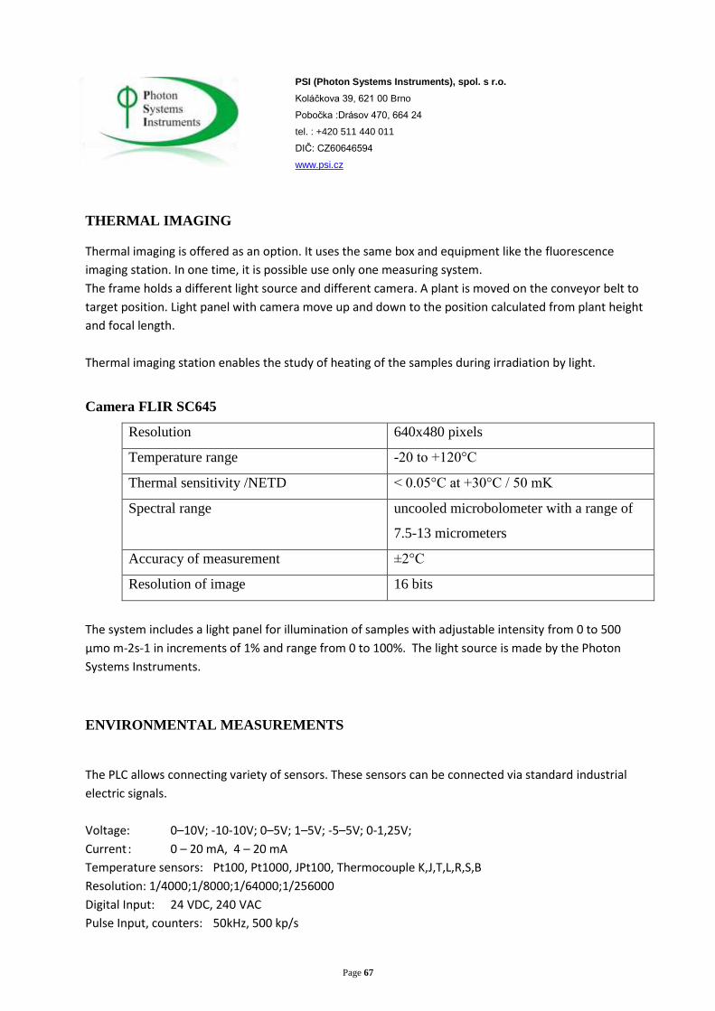
THERMAL IMAGING
Thermal imaging is offered as an option. It uses the same box and equipment like the fluorescence
imaging station. In one time, it is possible use only one measuring system.
The frame holds a different light source and different camera. A plant is moved on the conveyor belt to
target position. Light panel with camera move up and down to the position calculated from plant height
and focal length.
Thermal imaging station enables the study of heating of the samples during irradiation by light.
Camera FLIR SC645
Resolution 640x480 pixels
Temperature range -20 to +120°C
Thermal sensitivity /NETD < 0.05°C at +30°C / 50 mK
Spectral range uncooled microbolometer with a range of
7.5-13 micrometers
Accuracy of measurement ±2°C
Resolution of image 16 bits
The system includes a light panel for illumination of samples with adjustable intensity from 0 to 500
µmo m-2s-1 in increments of 1% and range from 0 to 100%. The light source is made by the Photon
Systems Instruments.
ENVIRONMENTAL MEASUREMENTS
The PLC allows connecting variety of sensors. These sensors can be connected via standard industrial
electric signals.
Voltage: 0–10V; -10-10V; 0–5V; 1–5V; -5–5V; 0-1,25V;
Current : 0 – 20 mA, 4 – 20 mA
Temperature sensors: Pt100, Pt1000, JPt100, Thermocouple K,J,T,L,R,S,B
Resolution: 1/4000;1/8000;1/64000;1/256000
Digital Input: 24 VDC, 240 VAC
Pulse Input, counters: 50kHz, 500 kp/s

Page 68
PSI (Photon Systems Instruments), spol. s r.o.
Koláčkova 39, 621 00 Brno
Pobočka :Drásov 470, 664 24
tel. : +420 511 440 011
DIČ: CZ60646594
www.psi.cz
For using smart sensors or decentralized system, it is possible to use serial communication like:
RS-232, RS-485, RS-422, Ethernet 100 Base-Tx, CAN, CompoNet, CompoBus, Controller link.
Protocols: ModBus RTU, ASCII, TCP; Ethernet TCP/IP, UDP; DeviceNet; CompoNet; PROFINET-IO;
FINS/UDP; CompoWay-F; Host link; User protocol.
PLC with I/O and communication units is an interface between process and supervisor PC. PLC sends
process information to the server, which saves data to a database. PLC can be equipped with a Flash
memory card with capacity 512MB and thus log information if server is not connected.
Minimum sampling period for sensor reading and data saving is 1 s. Sampling period can be set via
Supervisor program. The system can save all data and then process their averaging, maximum /
minimum value in interval…
A user can use his own sensors with standard industrial signals or the Photon Systems Instruments
Company can deliver required amount and type of sensors with the system.
SPRAYING
Spraying is offered as an option and it serves for automatic spraying plants by water or other solution,
like pesticides. The spraying system is located on the conveyor belt. Plants are moved for spraying
automatically and it is possible to control the process from supervisor program.
All components have at least IP 65 protection.
The system includes:
Conveyor belt
Spray
High pressure pump
Solenoid valves
Pipes
Tank for solution
Connection to water supply
Waste reservoir
Page 69
PSI (Photon Systems Instruments), spol. s r.o.
Koláčkova 39, 621 00 Brno
Pobočka :Drásov 470, 664 24
tel. : +420 511 440 011
DIČ: CZ60646594
www.psi.cz
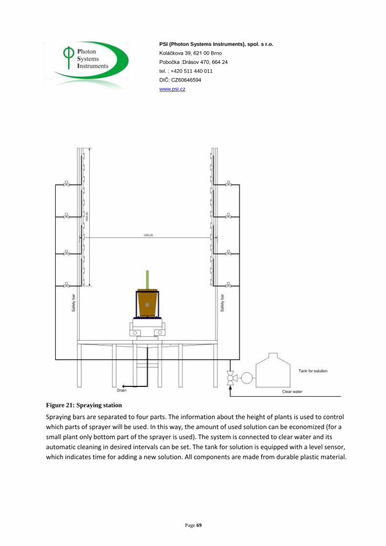
Figure 21: Spraying station
Spraying bars are separated to four parts. The information about the height of plants is used to control
which parts of sprayer will be used. In this way, the amount of used solution can be economized (for a
small plant only bottom part of the sprayer is used). The system is connected to clear water and its
automatic cleaning in desired intervals can be set. The tank for solution is equipped with a level sensor,
which indicates time for adding a new solution. All components are made from durable plastic material.

Page 70
PSI (Photon Systems Instruments), spol. s r.o.
Koláčkova 39, 621 00 Brno
Pobočka :Drásov 470, 664 24
tel. : +420 511 440 011
DIČ: CZ60646594
www.psi.cz
LOCAL INSTALLATION REQUIREMENTS
Power supply: 3+N+PE , AC 50Hz, 400V, 3x230V/100A
Compressed air: 10bar, 100 L/min. It is possible to deliver a separate compressor.
Water: > 3bar, 20L/min
Waste: Possibility to connect it to a drain system, only clear water, moister or solution from
watering or spraying are drained
Space needed in the control room or somewhere outside the greenhouse for control cabinet
installation.
Control cabinet dimension: 2000 x 2000 x 300 mm (w x h x l)mm
Ethernet connection with VPN for remote service and support.
INFORMATICS SYSTEM
Based on Central supervisor PC. Separate PCs are in the image stations and DataBase server. Computers
communicated via 1Mbit Ethernet network and TCP/IP. Informatics system runs on Windows.
It is possible to integrate our informatics system into existing informatics system. The system can
cooperate with existing databases.
Supervisor PC
To control process and to communicate with PLC. It is also used for changing data between technologies
and information systems; it runs measuring protocols. The operator communicates with the machine via
GUI, which primary runs on this computer in the control room. Remote clients can be connected. Clients
can work with their protocols. Service interventions are possible only from local machine or via a special
service client.
PSI cooperates on graphic design with its customers because each customer is unique requirements.
Basic level is the same. The first screen brings information about the system, its actual state, the most
important control buttons, information about the image station, live picture from the technology. Next
pages bring: protocol view, protocol edit, measuring data, measuring stations setting, manual control,
service, alarms, logs…

Page 71
PSI (Photon Systems Instruments), spol. s r.o.
Koláčkova 39, 621 00 Brno
Pobočka :Drásov 470, 664 24
tel. : +420 511 440 011
DIČ: CZ60646594
www.psi.cz
Figure 22: First page from the PSI’s PlantsSreen system
Protocol:
The system uses graphic interface for protocol writing.
Figure 23: Protocol edit page

Page 72
PSI (Photon Systems Instruments), spol. s r.o.
Koláčkova 39, 621 00 Brno
Pobočka :Drásov 470, 664 24
tel. : +420 511 440 011
DIČ: CZ60646594
www.psi.cz
Basic functions are:
“Measuring”
A user can choose from list of measuring station, which will be used in the actual step:
Hyperspectral SWIR
Hyperspectral VNIR
RGB all cameras
Weight
Watering
Weight + Watering
Optionally:
Fluorescence/Thermal imaging
Spraying
In one cycle, a user can choose all types of measuring, or just some of them, or none of them. For each
measuring different protocol can be chosen.
“Delay”
A user can choose delay between single steps.
Absolute delay – waits for defined day time
Relative delay – waits defined time from the last step
Relative delay with date – waits for day and time defined, allow starting the experiment in defined day
and time
These options allow scheduling experiment start at the same time of day, or starting experiments with
defined delays between them.
“Repeat”
Includes two settings:
Counter – how many times
Step – from which step the next round will start
This function works like a loop. A user defines Starting point in an experiment and the end point is
defined by Repeat. A user defines how many times will be the loop repeated. The loop can be repeated
endlessly and stopped manually.

Page 73
PSI (Photon Systems Instruments), spol. s r.o.
Koláčkova 39, 621 00 Brno
Pobočka :Drásov 470, 664 24
tel. : +420 511 440 011
DIČ: CZ60646594
www.psi.cz
A protocol can be saved to a file or loaded from a file. It can be paused in running or cancelled. If a
protocol is cancelled during its running, and if pots are not in the growing part in starting position, the
system automatically moves all pots into starting position without stops. Every time, pots go in the same
sequence if not changed before the protocol start.
A protocol can be written or modified in remote client and then saved to file in the Supervisor PC and
then runs from this file.
Pot and Batch Selection
The system allows making batches from pots in growing chambers. Each batch can has own independent
protocol. If two batches have planned measuring cycle at same time, an error occurs.
The system can serve for more users that will do different experiments with different plants.
Buffer Control Screen
Figure 24: GUI buffer display
On buffer screen, it is displayed the growing buffer with all positions.
Green – position is occupied by plant
Gray – free position
Red – line error, line cannot be used
Yellow – batch

Page 74
PSI (Photon Systems Instruments), spol. s r.o.
Koláčkova 39, 621 00 Brno
Pobočka :Drásov 470, 664 24
tel. : +420 511 440 011
DIČ: CZ60646594
www.psi.cz
Click on the position and information like: ID, barcode, notes, batch competency, date when pots was
added to system is displayed.
Batch can be modified and it is possible to choose one or all batches.
Multiple selection via Ctr+clic or Drag and drop is possible.
The closest line to image station can be used for temporary plant. Temporary plants are put from
loading space. One batch contains only temporary plants. This batch runs its own separate protocol with
same rules like regular batch.
Option function: For temporary plants can be used transport lines, but then this plant block starting
measuring action in protocol. Warning appears when line is blocked and measuring in protocol is
planned.
If the closest line is empty it is possible to move plants between the lines independently on
running experiment. If no experiment is running, it is possible to use image line for the same
function.
Individual plant or batch can be chosen and transported to a loading space where it can be
removed. Extra plants can be added to the system if there is space enough. Actual occupation is
displayed on the supervisor screen.
A user can choose free line in which he plans to put new pots before starting filling process. If no
line is chosen, the system automatically put pots to free lines.
PCs in Image Station
Some image stations, which need a lot of computing power and which calculate results in real
time, like the fluorescence station, have their own PC that communicates with the supervisor PC.
Measured results are saved in local discs and then sent to database.
DATABASE COMPUTER
Database machine is a server PC with capacity at least 10 TB. The MySQL database version
5.5.22 or higher is used. Standard TCP is used.
It is possible to integrate this system into current informatics network. The system can cooperate
with central server and send data to central server.
All measured data are stored into a relational MySQL database. It is possible to search the
measured data by selected parameters. The user may select the necessary data for its processing.

Page 75
PSI (Photon Systems Instruments), spol. s r.o.
Koláčkova 39, 621 00 Brno
Pobočka :Drásov 470, 664 24
tel. : +420 511 440 011
DIČ: CZ60646594
www.psi.cz
Number of measurements depends on the size of storage space. It is possible to record up to
1000 measurements on 200 gigabytes.
The server saves all data from the following processes:
Measuring data, images, setting of measurement equipment
Alarms, warnings
Data from environment sensors
Protocols
Users can see and work with data via programs which can analyze image data, drawing trends,
plot results in time. It is possible to do the same experiment in long period and then see data in
time. Measuring data are identified by unique ID.

Page 76
PSI (Photon Systems Instruments), spol. s r.o.
Koláčkova 39, 621 00 Brno
Pobočka :Drásov 470, 664 24
tel. : +420 511 440 011
DIČ: CZ60646594
www.psi.cz
Figure 25: Basic database structure
Page 77
PSI (Photon Systems Instruments), spol. s r.o.
Koláčkova 39, 621 00 Brno
Pobočka :Drásov 470, 664 24
tel. : +420 511 440 011
DIČ: CZ60646594
www.psi.cz
BASIC DATABASE STRUCTURE:
Preparing an Experiment
A user operates handheld barcode and RFID reader to put a new holder and pots into the system. Each
item can have its own description. Each item includes the day when was put into the system. It is
possible to edit information about plants that are included in the system.
Plants with holders are put on the belt in loading space. A user can choose which line will be used.
Loading pots are moved through RFID and barcode sensor and settled in a chosen line. The system gets
information about each pot location.
Data Structure
The system data, like image data, weight etc., have same structure.
“ImageStationName-HolderID-PotID-DateTime.xxx”
Example from the PlantScreen system:
Local disc content file “PlantScreenResult” with files "RGB1-Tray scan 16-12-10-2011-6-25-03-AM.png"
RGB1 – identify image station and camera
Tray scan16 – name of tray
12-10-2011-6-25-03-AM – date and time
Data name structure can be modified according to customer’s requirements.
Power Failure
The PLC has a part of permanent memory. This memory part includes information about the system
before power failure. After the system is powered on again, it is able to continue from the same step.
PC and informatics system have UPS to save actual state into permanent memory. After power is on, the
PC can continue from the last saved step.
If measuring protocol runs before power failure, the protocol can either continue or all pots can move to
a starting position. Imaging, which is running when power fail and cannot be finished, can start again
when the power is back.
Time of power failure with code of error is written into a log file.
UPS parameters: at least 1000 W in 5 minutes.

Page 78
PSI (Photon Systems Instruments), spol. s r.o.
Koláčkova 39, 621 00 Brno
Pobočka :Drásov 470, 664 24
tel. : +420 511 440 011
DIČ: CZ60646594
www.psi.cz
Messages
The system can send emails with errors, warnings or actual state to a predefined address. If the system
includes a GSM module, it can send short messages with errors independently on main power and
Ethernet connection.
FUTURE EXPANSION
The system is designed for updates in future and for adding new functionalities if there is free space in
the greenhouse. One or more growing lines can be modified to measuring lines. The PLC has much free
capacity. If more complex system will be required, decentralized structure with two or more PLC’s can
be used. Communication capacity is much bigger then direct I/O.
It is possible to add a new PC into the basic information system. Thus the data storage capacity can be
significantly increased.
Updates and software repairs are free. Adding new functionality, which is not described in this
document, will depend on a separate contract.
PSI is committed to the future development of this system.
.
SERVICES AND SUPPORT
24 hour online support by phone or email
Remote VPN connection for remote software support
Free updates
Separate service contract
SAFETY REQUIREMENTS
System and all parts comply with laws and regulations concerning safety and health.
Include Machinery Directivity (2006/42/EG)
Low Voltage Directivity (73/23/EEG)
Electromagnetic Compatibility Directive (EMC)(2004/108/EG)

Page 79
PSI (Photon Systems Instruments), spol. s r.o.
Koláčkova 39, 621 00 Brno
Pobočka :Drásov 470, 664 24
tel. : +420 511 440 011
DIČ: CZ60646594
www.psi.cz
SAFETY FEATURES
Emergency stops are accessible from each part of system. There are sensors on the door or light curtain; these sensors stop the system when someone enters the inside part. All moving parts are isolated from the space where users are intended to stand and/or to manipulate with pots.
Controlled Cultivation Environments for Plant Phenomic Screening
PSI designs and builds high-capacity growth chambers (Fytotrons) which allow researchers to program
controlled growing conditions, with accurate measurements and regulation of temperature, irradiation
cycles and relative humidity. The Fytotrons may contain eithe conveyor-based or robotic imaging
systems, or may incorporate conveyor systems that transport the plants from the Fytotron to a Plant
Screen imaging system . The chambers must allow a range of programmed day / nightcycles with
wavelengths and other conditions regulated for dawn / dusk tansitions.
The following description relates to a Fytotron facility installed at the University of Olomouc in the Czech
Republic. Numerous sizes, configurations and specifications of Fytrotrons may be built to suit a client’s
specifi requirements. Automated intelligent greenhouses are also available from PSI, custom-designed
for the klient.
Dimensions
Growth areas: Cultivation facility including automated hydroponic nutrient delivery is
equipped with two floors, in which each floor is divided into four parts.
There eight growth areas available as a whole. LED panels provide lights
to the lower shelf, and more LED panels in the ceiling of the Fytotron
provide light to plants on the upper shelf.
Internal dimensions: 6.750m (w) x 5.265m (d) x 2.800 \m (h.
External dimensions: 7.200 m (width of row) x 5.775m (d) x 3.900m (h)
Growth area: 9.5 m2
Growth height: Minimum 2.0 m from the base of plants up to the lower edges of lights.
Temperature range: Selected by client
Stability: Turning the lights On / Off: ± 1°C
Regularity: Turning the lights On / Off: ± 2°C

Page 80
PSI (Photon Systems Instruments), spol. s r.o.
Koláčkova 39, 621 00 Brno
Pobočka :Drásov 470, 664 24
tel. : +420 511 440 011
DIČ: CZ60646594
www.psi.cz
Lighting: Each growth area has its own control unit with independent control and
regulation.
Maximum Irradiance: 1000 mol/m2/s at 30 cm from the lights.
Regulation Range: 0% to 100%of maximum in 1% increments. Light intensity is controlled
in software for each growth area individually over its entire range.
Humidity Range: 40% RH. – 80% RH.
Insulation
Interior surfaces
Covering layer of sandwich panels consisting of hot-dipped galvanized steel sheet painted with powder
coating. This ensures a hygienically smooth and durable surface even on inaccessible edges, and also
perfect corrosion protection.
Exterior
The Fytotron chamber is composed of modular layered panels with a thickness of 80 mm consisting of
an inner layer of foam polyurethane on a substrate of galvanized steel sheet painted with a white
powder coat. The connection of panels (floors, walls, ceiling) is engineered using a self-centering slot-
key system. Eccentric clamping locks have plastic covers, and fastening hooks are protected against
corrosion.
Door
Refrigerator double rotary door 1600x1970 mm. Metallic, layered with shell made of double-sided
galvanized sheet. Surface-modified by polyester coat. Hue of door and frame RAL 9010 (white). The
door is locked from the outside, but it is always possible to open it from inside - even when locked.
Insulation Material
Polyurethane foam. Coefficient of thermal conductivity = 0.025 W/mK.
Insulated Floor
Floor of the Fytotron are made from insulation panels covered with humidity resistant plywood and
aluminum tread plate.

Page 81
PSI (Photon Systems Instruments), spol. s r.o.
Koláčkova 39, 621 00 Brno
Pobočka :Drásov 470, 664 24
tel. : +420 511 440 011
DIČ: CZ60646594
www.psi.cz
Temperature Control and Air Distribution System
The Fytotron is built as a low-energy device which, with year-round operation -will provide the user with
significant savings in operating costs compared to conventional systems. Emphasis is placed on the
following factors:
Maintaining temperature in range of 10 to 40°C in increments of +-1°C
Maintaining a humidity in range of 40 and 80% in increments of +-5%
Maintaining a homogeneous field and air flow
Principles of Reducing Energy Input
Maximize elimination of hydrothermal loads
Use new low-energy technologies for air humidification
Use new low-energy technologies for air dehumidification
Appropriate design of elements to reduce pressure losses
Appropriate placement of active elements to increase the system efficiency
Use of sensors to capture all changes of monitored variables for most efficient control of
environment.
Elimination of Thermal Loads
Thermal load is comprised of:
Thermal load of lights
Thermal load of fresh air delivery
Thermal load of air-conditioning
Opening of doors, movement of people ....
Thermal load of active technologies within the FytoScope (e.g. conveyor)
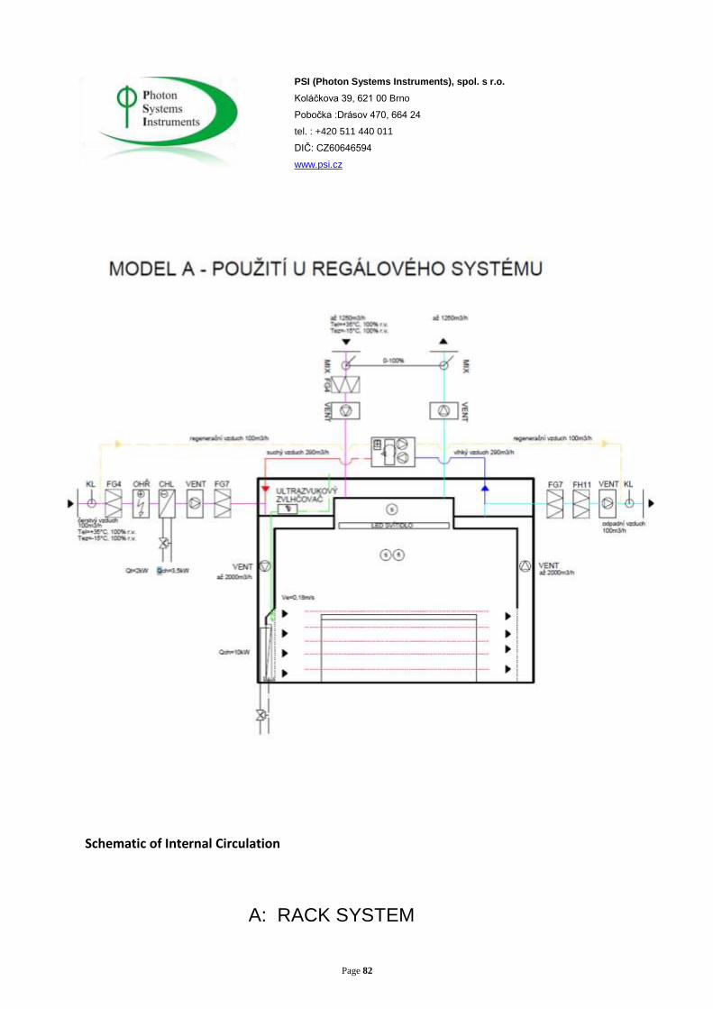
Page 82
PSI (Photon Systems Instruments), spol. s r.o.
Koláčkova 39, 621 00 Brno
Pobočka :Drásov 470, 664 24
tel. : +420 511 440 011
DIČ: CZ60646594
www.psi.cz
Schematic of Internal Circulation
A: RACK SYSTEM

Page 83
PSI (Photon Systems Instruments), spol. s r.o.
Koláčkova 39, 621 00 Brno
Pobočka :Drásov 470, 664 24
tel. : +420 511 440 011
DIČ: CZ60646594
www.psi.cz
B: AIR TRANSIT
FRESH AIR
DEVALUED AIR
REGENERATION AIR
WET AIR
DRY AIR
WATER STEAM
PRE-MODIFIED WATER
VALVE
MIXING VALVE
FILTER OF FILTRATION CLASS
BY THE (EN779)
ELECTRIC HEATER
WATER COOLER
HIGH CAPACITY COOLER
FAN

Page 84
PSI (Photon Systems Instruments), spol. s r.o.
Koláčkova 39, 621 00 Brno
Pobočka :Drásov 470, 664 24
tel. : +420 511 440 011
DIČ: CZ60646594
www.psi.cz
Cooling
For the production of cold water, there is a compact air-cooled chiller designed with scroll compressor
and reverse valve (heating function). R410A is used as a refrigerant. Year-round efficiency of the
E.S.E.E.R cooling machine is around 4 (W / W). The device is equipped with regulation for winter cooling
operation at low temperatures.
Cooling medium is cold water containing 35% ethylene glycol. In order to ensure the maximum cooling
effect, each Fytotron chamber has its own cooler. As opposed to the central device, this cooler allows
independent control of two parameters of coolant:
a) Mass flow rate regulation by three-way valves
b) Temperature gradient of water to reduce the share of fixed cooling energy during periods of high
indoor temperature and relative humidity. At low water temperature, unwanted dehumidification and
loss of energy takes place, because the exhaust air from the radiator requires rehumidification.
Fresh Air Supply
Fresh air supply is necessary within the Fytoscope, but causes a hydrothermal load. By optimizing air
flow rate the energy cost of supply can be reduced up to by 30%. Fresh air is drawn through the primary
filters G4 (according to EN779), then its temperature is modified to the desired temperature. Its
humidity is not modified by preheating and condensation. Air is filtered by the second stage of G7
filtration (according to EN779). Excess fresh air is exhausted through a HEPA filter H14 (according to
EN779) with prefilter G7 (according to EN779). It is transported by pipeline to the outside area. The
entire inlet and outlet of fresh air is controlled by a central MaR system that monitors the temperature
of the supply air, sedimentation of all levels of filtration and operation of fans( with warning s for
unusual operation).
Elimination of Pressure Losses
The use of large cooling exchangers reduces energy losses. The construction of large aluminum groins
and copper waterways results in minimum pressure loss up to 10 Pa on the air side, and thereby
facilitates the use of transport ventilators for circulation of air with low pressure.
Design of fans without a spiral box and with blades curved backwards also contributes to high efficiency
with low power consumption. More fans are used to ensure even distribution of air in the cooled wall.
This also ensures even flow over the large-area exchangers.

Page 85
PSI (Photon Systems Instruments), spol. s r.o.
Koláčkova 39, 621 00 Brno
Pobočka :Drásov 470, 664 24
tel. : +420 511 440 011
DIČ: CZ60646594
www.psi.cz
Flow rate through the heat exchangers is small (up to 0.2 m / s) compared to the flow of heat
exchangers for common air conditioning systems,
(up to 3 m/s). Condensate flows into an open condensate tank, so there is no risk of entrainment by air
flow and use of drop eliminators, which would increases pressure losses in the system. Another benefit
is the reduction of radiated heat due to fan air flow.
Required cooling capacity of 10 kW at an annual effectivity of cooling source E.S.E.E.R = 4.0 results in a
consumption of 2.5 kW, equal to 21 900 kWh per year
Additional Reduction of heat load of 3.0 kW at an annual effectivity of cooling source E.S.E.E.R = 4.0
results in consumption of 0.75 kW, equal to 6 570 kWh per year
The energy consumption for ventilation (1040 m3 / h) is 0.4 kW per year equal tp 3 504 kWh
Chamber Hydroponic Tables Conveyor Belt XYZ Robotic System
Input of Lights 10 12 6
Cooling of lights 10074 12264 6132
Consumption of
electric motors
454 544 272
Cooling 21900 26280 13140
Saving of kWh /
year
11372 13472 6736
Note: Savings refer to year-round operation of cooling at the given input of lights and E.S.E.E.R. = 4.
Contribution of cooling pump to total consumption for cooling is not assumed.
Additional savings of 100 kWh can be achieved by regulating of the air flow with regard to outside
temperature.

Page 86
PSI (Photon Systems Instruments), spol. s r.o.
Koláčkova 39, 621 00 Brno
Pobočka :Drásov 470, 664 24
tel. : +420 511 440 011
DIČ: CZ60646594
www.psi.cz
Lighting Systems
Two sets of LED banks within the Fytotron allow for two levels of cultivation. One set of banks is located
in the ceiling, and the other above the lower cultivation area. The LEDs produce very little irradiant
heat. The thermal load from cooling the panels themselves. Is dissipated by the efficient heat exchange
system that removes up to 70% of thermal load. This represents a significant cost savings compared to
standard methods of cooling.
LED Lamps
Intensity of irradiance min. 1000mol m-2s-1 at a distance of 1.0 m.
White with supplemental IR. Spectral range from 430 to 730 nm.
Simulation of light modes (e.g. fluctuation, clouds, day, night, dawn, dusk, etc.).
Operation modes - continuous light, harmonically modulated light, user-modulated light.
Light dimensions 800 mm x 270 mm
Light radiates minimum thermal energy.
Inhomogenity of light max. ± 5%.
Can be set in maximum increment of 0.5% or 2 mol m-2s-1.
Independent regulation of the intensity of white light and IR.
Radiating angle of light max 10°.
The light is thermally insulated from its own chamber.
Lifetime of LED modules at least 90 000 hours at 1% tolerance of defective diodes.

Page 87
PSI (Photon Systems Instruments), spol. s r.o.
Koláčkova 39, 621 00 Brno
Pobočka :Drásov 470, 664 24
tel. : +420 511 440 011
DIČ: CZ60646594
www.psi.cz
The range of used LEDs
Light spectrum
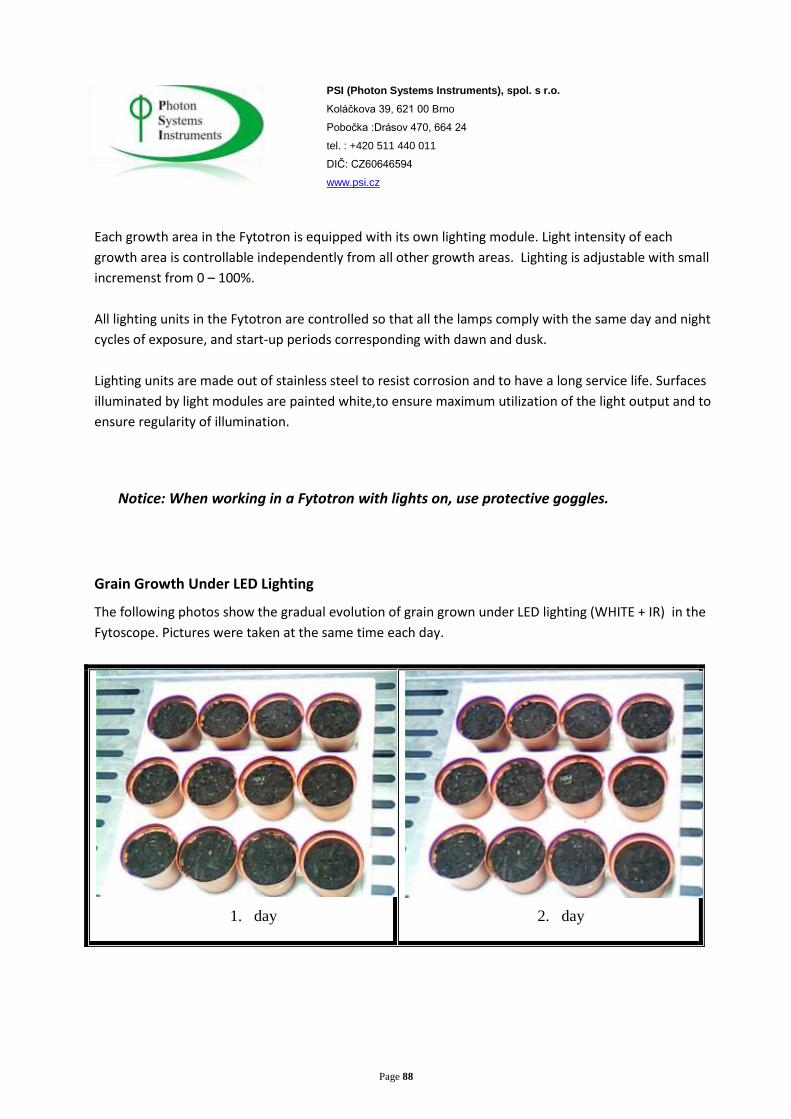
Page 88
PSI (Photon Systems Instruments), spol. s r.o.
Koláčkova 39, 621 00 Brno
Pobočka :Drásov 470, 664 24
tel. : +420 511 440 011
DIČ: CZ60646594
www.psi.cz
Each growth area in the Fytotron is equipped with its own lighting module. Light intensity of each
growth area is controllable independently from all other growth areas. Lighting is adjustable with small
incremenst from 0 – 100%.
All lighting units in the Fytotron are controlled so that all the lamps comply with the same day and night
cycles of exposure, and start-up periods corresponding with dawn and dusk.
Lighting units are made out of stainless steel to resist corrosion and to have a long service life. Surfaces
illuminated by light modules are painted white,to ensure maximum utilization of the light output and to
ensure regularity of illumination.
Notice: When working in a Fytotron with lights on, use protective goggles.
Grain Growth Under LED Lighting
The following photos show the gradual evolution of grain grown under LED lighting (WHITE + IR) in the
Fytoscope. Pictures were taken at the same time each day.
1. day
2. day

Page 89
PSI (Photon Systems Instruments), spol. s r.o.
Koláčkova 39, 621 00 Brno
Pobočka :Drásov 470, 664 24
tel. : +420 511 440 011
DIČ: CZ60646594
www.psi.cz
3. day
4. day
5. day
6. day
7. day
8. day

Page 90
PSI (Photon Systems Instruments), spol. s r.o.
Koláčkova 39, 621 00 Brno
Pobočka :Drásov 470, 664 24
tel. : +420 511 440 011
DIČ: CZ60646594
www.psi.cz
9. day
10. day
Humidification System and Humidity Regulation
Low-Energy Humidification System
An ultrasonic humidification system is used in the Fytotron. By comparison, conventional team
humidification requires nine times more energy-intensive or the same result. Another advantage of
water vapour produced by ultrasound is its low temperature, which eliminates excessive condensation.
As a result there is no formation of mineral deposits from minerals contained in the water. The
ultrasonic humidifier operates on the principle of high frequency vibration of metal membranes that
create an ultra-fine mist during contact with the water surface. The water must be sterilized in advance,
using UV filtration, to prevent the release of microorganisms into the air. Water vapor moves through
distributors into the stream of circulating air, after heat treatment to ensure the required humidity of
supply air.
The total costs of humidification depends on the RH conditions chosen by the user. However, it is
possible to compare the total cost of operation with other systems.
Comparison of cost for various types of humidification technologies for
18 kg of water
For 18 kg of water Steam
Humidification Water Jets
Air Pressure
Jets Ultrasound
input (W) 13 500 2 700 2 250 1 440
Estimated cost per year $15768 US $3154 US $2628 US $1665 US
Estimated cost for 5
years $78840 US $15768 US $13140 US $8326 US

Page 91
PSI (Photon Systems Instruments), spol. s r.o.
Koláčkova 39, 621 00 Brno
Pobočka :Drásov 470, 664 24
tel. : +420 511 440 011
DIČ: CZ60646594
www.psi.cz
Adsorption Dehumidification System
An important element in the reduction of energy costs is the use of an adsorption method of
dehumidification. A Dehuter-rotor technology is used in which water vapour from chamber air is
absorbed into rotary heat exchanger plates formed from high absorption materials. After the plates are
saturated by moist air, regeneration takes place through dehydration by dry regenerative air that
dehumidifies the rotor blades. Regeneration rate (6-10 x / h) is determined individually and controlled
by an automatic measuring and regulation system. This system operates at low temperatures and high
efficiency compared to conventional dehumidification based on condensation saving up to 50% of
energy costs.
Air Filtration
HEPA Filtration for Exhaust Air
Each zone of the Fytotron is delivered with a connection for exhaust air duct.
Piping system is designed so that it is possible to perform volumetric tests of all filters used to
filter the exhaust air from the Fytotron.
The air leaving the Fytotron is filtered according to the requirements of the GMO2.
The outlet pipe of the ventilation system includes a HEPA filter.
The device is designed to measure pressure losses on the filter. If the pressure value indicates
that the filter has reached its maximum of recommended pressure drop, it activates a warning
signal and the filter must be replaced.
The filter is installed in a special box equipped with gel seal and appropriate pre-filter.
The filter is exchanged securely from the inside of the chamber. The technician is protected
from contact with pollutants that may be found on the surface of filter.
Fan on the output system has controllable speed to allow the chamber to maintain specific
constant pressure with respect to exterior pressure.
HEPA Filtration of Supply Air
Each zone of the Fytotron has a connection for air supply with a mounted special box for an inlet
filter equipped with gel seal.
Piping system is designed to allow volumetric tests on all filters used.
The air coming into the Fytotron is filtered according to user requirements to prevent contact of
samples with outdoor contaminantst (insects, dust, pollen). Filtering occurs in accordance with
GMO2.

Page 92
PSI (Photon Systems Instruments), spol. s r.o.
Koláčkova 39, 621 00 Brno
Pobočka :Drásov 470, 664 24
tel. : +420 511 440 011
DIČ: CZ60646594
www.psi.cz
The inlet duct ventilation system includes a HEPA filter.
The device is designed to measure pressure losses on the filter. If the pressure value indicates
that the filter has reached its maximum of recommended pressure drop, it activates a warning
signal and the filter must be replaced.
The filter is installed in a special box equipped with gel seal and an appropriate prefilter.
The filter is exchanged securely from outside of the chamber. The area above the chamber s
designed to allow easy service during which the internal environment of theFytotron is
protected from contact with outdoor concentrations of pollutants that may be found on the
surface of the filter.
Fan of the input system If the pressure value indicates that the filter has reached its maximum
of recommended pressure drop, it activates a warning signal and the filter must be replaced.
Management Software, Data Acquisition and Storage
Control software
Software is installed on a PC, which is installed with the Fytotron .
Compatible with Microsoft Windows© operating system including Windows
95/98/NT/2000/ME/XP.
Communicates with control panels of Fytotrons via Ethernet / LAN system.
Pssword configured for permitted-user access only
Allows users to change protocols remotely.
Generates reports with current conditions and error messages.
Generate email notification about Fytotron status and error messages.
Graphical display of temperature, humidity and light intensity and analysis.
Main Screen
Shows actual and preset values of temperature, relative humidity and individual lights. Graph shows
curves of all measured functions.

Page 93
PSI (Photon Systems Instruments), spol. s r.o.
Koláčkova 39, 621 00 Brno
Pobočka :Drásov 470, 664 24
tel. : +420 511 440 011
DIČ: CZ60646594
www.psi.cz
Graph Screen
Screen depicts curves of all the quantities from the last 30 minutes to 12 hours (depending on setup).
Actual set temperature is plotted on the main Y axis. The secondary axis displays relative humidity
(actual and set) and light. Quantum yield (QY) is presented at a detached axis on the left next to the
temperature.

Page 94
PSI (Photon Systems Instruments), spol. s r.o.
Koláčkova 39, 621 00 Brno
Pobočka :Drásov 470, 664 24
tel. : +420 511 440 011
DIČ: CZ60646594
www.psi.cz
Individual parameters display can be turned on/off by ticking the check boxes. A Reset graph button
deletes all recorded curves in the graph and a new curve projection starts. This does not affect saved
data. A Full screen button switches the graph into aFull-Screen mode.
Full-screen mode enables a more detailed graphical presentation of data. Data are divided into two
graphs for greater clarity. The upper graph presents temperature (set and actual) and relative humidity
(set and actual). The bottom graph shows all light data and the time-course of fluorescence (QY), if
measured.
Protocol Screen

Page 95
PSI (Photon Systems Instruments), spol. s r.o.
Koláčkova 39, 621 00 Brno
Pobočka :Drásov 470, 664 24
tel. : +420 511 440 011
DIČ: CZ60646594
www.psi.cz
A Protocol tab enables the user to set the cultivation conditions. The protocol can be very simple, such
as unchanging parameters during the whole experiment, or it can involve diurnal changes in light,
temperature and humidity that simulate complex changes in the natural environment. Each protocol
can be saved to a file and opened again later.
The FluorPen
The FluorPen is an optional device to take spot measurements (not images)of chlorophyll fluorescence
kinetics. Readings from the FluorPen can be viewed and stored in the FytoScope softwae. If the
FluorPen is connected to the FytoScope and switched on during the program, it is recognized by the
program and a tab Pen appears in the main menu. The FluorPen measures only steady state
fluorescence (Ft) and quantum yield (QY) when in on-line mode.

Page 96
PSI (Photon Systems Instruments), spol. s r.o.
Koláčkova 39, 621 00 Brno
Pobočka :Drásov 470, 664 24
tel. : +420 511 440 011
DIČ: CZ60646594
www.psi.cz
The Pen tab has control features for the FluorPen use:
Get QY – starts fluorescence kiunetics measurements. The measurement of QY takes several seconds.
Afterwards measured values and measure time appear in the cells Last measured QY, Last measured Ft,
and Last measure Time.
Start Auto and Stop Auto –Allows measurements to be carried out continuously, regularly, and within a
particular period. The period of an automatic measurement is set in the Measure period cell. The period
is entered in minutes. By touching Start auto and Stop auto buttons, an automated sequence of readings
is started or stopped. The current state of the protocol is displayed in the State cell.
Read values of QY and Ft are added to a list on the left in the Pen tab, both during automatic and
manual measurement. Values are display in the graph in the Main tab.
Clear List – erases the chart with measured values in the Pen tab (it does not affect stored data).