psb dsp based rf low level control: operations and diagnostics 27/1/15 m.e. angoletta, a. findlay,...
TRANSCRIPT

1
PSB DSP based RF low level control: Operations and Diagnostics
27/1/15
M.E. Angoletta, A. Findlay, M. Jaussi, J. Molendijk.

2
Introduction
• Consolidation was required to keep the PSB LL reliable & flexible for the upcoming LIU upgrades such as L4 injection, 2 GeV/c extraction and controlling Finemet or upgraded ferrite cavities.
• Part of a plan to consolidate all of the Meyrin machines LL systems.
• New HW, firmware and software but an attempt was made to keep with in the existing “feel” for the operations crew with working sets, samplers and OASIS integration where possible.
• We’ll present the basics of how to operate the new LL system and show what diagnostics are available (or soon will be!)

3
• Very similar overall to existing LL RF systems, but the new systems interfaces are delivered in full “expert version” that can be a little daunting.
• RF synoptics are the chosen expert tool to get the overview of how to control most of the parameters, but these are also available via the working sets (WS) if one knows where to look!
• The WS are typically what the operations crew prefer to use, but the large number of parameters for the LL RF make these complicated to the casual user.
• We are working to simplify the more complicated knobs and will then be able to generate WS in collaboration with OP that only show the basic options required for everyday operation. This should be completed by end of February 2015.
• The timings that are missing the BAX0-4 prefix will be renamed by end Feb 2015.• To observe the inputs, outputs & signals within the system, samplers and OASIS are still used,
although many signals only exist in the digital domain.• The OASIS signals are presently being reorganized to remove old signals and try to arrange the
new ones in a simple order.

4
• The new system is based around 3 DSP motherboards and the functions performed are split between the 3.
• According to the functions performed by the motherboard, it’s two daughter card slots are equipped with a Master Direct Digital Synthesizer (MDDS), a DAC also known as a Slave Direct Digital Synthesizer (SDDS) or an ADC also known as a Digital Down Convertor (DDC).
• DSPA takes care of the frequency program & radial loop.• DSPB takes care of the phase loop(h=1 & h=2), synchronisation loop, as
well as the master clock.• DSPC looks after the C04 phase loop, the C16 blow up and the
generation of the drive signals for the cavities.• There are 3 CTRVs in the system, but many timings are generated
internally and do not pass through the CTRVs.

5
What’s required to operate the Digital LL RF system?
• As with the old system, the basic processes remain the same:– Phase loop– Second harmonic control– Radial loop– Capture– C16 blow up– Synchronisation loop

6
What’s required to operate the Digital LL RF system?• Synoptics & Working Sets give access to everything needed.• A copy of each synoptic can be found at the end of the presentation.

7
What’s required to operate the Digital LL RF system?
• Primary Phase Loop: Important Parameters & Functions– Phase loop start timing BAx.SPL_H1 from
WS– Adjust Phase loop gain function
BAx.FGPLGAIN, too little gain may provoke losses, too much may provoke oscillations and perhaps losses.
– Phase offset function BAx.FGBEAMPOFF is typically disabled as unused presently.

8
What’s required to operate the Digital LL RF system?
• Primary Phase Loop: Signals to Observe– The primary phase loop response can be
observed on the samplers BAx.BEAMPH_H1-SD or on OASIS BAx.BEAMP_H1-DS and used to check when the phase loop is switched on and if there is too much or too little gain with BAx.SPL_H1 & BAx.FGPLGAIN.
– The function BAx.FGPLGAIN can also be observed on the samplers BAx.FGPLGAINH1-SD or OASIS BAx.FGPLGAIN-DS
– Phase PU signals are on OASIS BAx.PHASE_PU_AVC-AS and can be used to check that there is an input for the phase loop.

9
What’s required to operate the Digital LL RF system?• Second Harmonic Control: Important Parameters & Functions
– The second harmonic is used to increase the available bucket size and control the bunch shape via the the C04 voltage function BAx.FGVRFC04 and the programmed relative phase between C04 & C02 through function BAx.FGC04PHC02.
– In our typical double harmonic operation, BAx.SPLC04-C02 is enabled from the start of the cycle, locking the C04 phase to the C02 .
– The C04 Phase Loop can also lock the C04 to the beam in place of the C02, when BAx.SPLC04-BEAM is enabled. There are no users presently where this has been used.
– Once close to the extraction FT, the beam can be split in two with the voltage functions, then transferring beam phase control from the Primary Phase Loop to the Secondary Phase Loop enabling BAx.SPL_H2.
– There is a soft switching from Primary to Secondary Phase Loop that can be found on the Primary or Secondary Phase Loop synoptic called PL H2 Transition Duration [ms] and is typically 1-5ms.

10
What’s required to operate the Digital LL RF system?• Second Harmonic Control: Signals to Observe
– The Tomoscope or BSM will give the simplest indication of the phase between the cavities, the timing BAx.SPLC04-C02 starts the phase lock and function BAx.FGC04PHC02 programs the phase between the cavities.
– When C02 & C04 are in phase one observes a tall and short bunch, when out of phase a lower and longer bunch, but both depend upon how much voltage is on each cavity.
– The H2 Phase Loop response can be observed on the samplers via BAx.BEAMPH_H2-SD or on OASIS BAx.BEAMPH_H2-DS.

11
What’s required to operate the Digital LL RF system?• Radial Loop: Important Parameters &
Functions– The Radial Loop start timing BAx.SRL. Note that
the Radial Loop will automatically be opened by the Synchronization Loop on the extraction FT.
– The choice of pick-ups to be used for the Radial Loop “TPUs to use for radpos calculation” in synoptic or “Radial PU2use Mask” in BAx.DSPA knob. This allows the use of all, none or any selection of the 4 available pick-ups.
– The Radial Loop Gain function BAx.FGRLGAIN is used to adjust the loop gain.
– The Radial Loop Steering function BAx.RSTEER is used to program the desired horizontal position throughout the cycle.

12
What’s required to operate the Digital LL RF system?
• Radial Loop: Signals to Observe– To observe the overall Radial Loop response in mm on
the samplers use BAx.RPOS-SD and on OASIS BA4.AVRPOS_MM-DS.
– The MRP sampler will also show the radial position but using all 16 pick-ups instead of 4.
– If oscillations are observed on the overall response try reducing the gain function BAx.FGRLGAIN
– The beam is deliberately steered to -2mm before the synchronization to smooth the transition of control from Radial to Synchronization Loops.
– If there is a doubt about if one (or more) of the transverse pick-ups is working, these can be observed on OASIS with BAx.RPOS_TPUx_MM-DS. The mask can be changed to exclude faulty pick-ups, and the loop will work OK, but for best results all 4 pick-ups should be used.

13
What’s required to operate the Digital LL RF system?
14
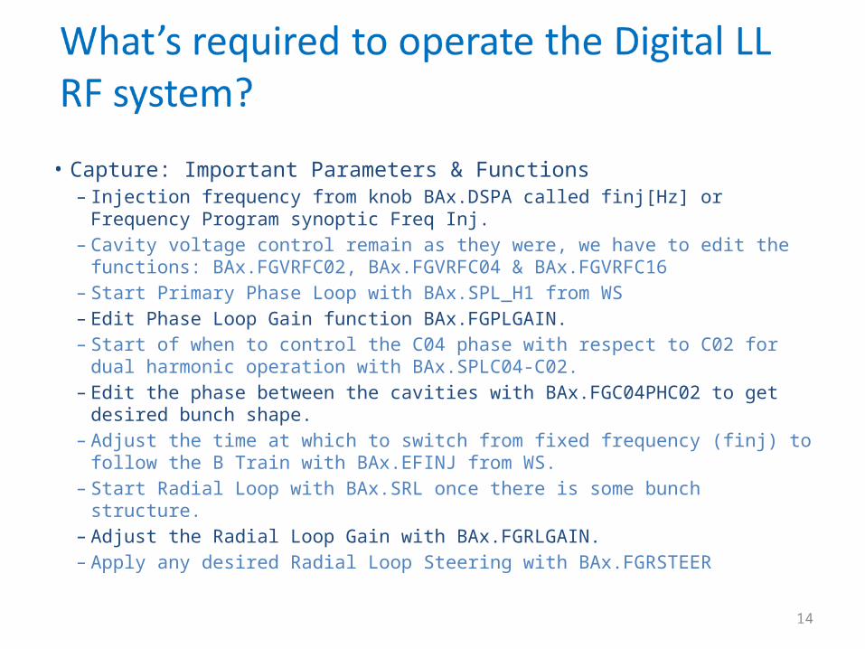
• Capture: Important Parameters & Functions– Injection frequency from knob BAx.DSPA called finj[Hz] or Frequency Program
synoptic Freq Inj.– Cavity voltage control remain as they were, we have to edit the functions:
BAx.FGVRFC02, BAx.FGVRFC04 & BAx.FGVRFC16– Start Primary Phase Loop with BAx.SPL_H1 from WS– Edit Phase Loop Gain function BAx.FGPLGAIN.– Start of when to control the C04 phase with respect to C02 for dual harmonic
operation with BAx.SPLC04-C02.– Edit the phase between the cavities with BAx.FGC04PHC02 to get desired bunch
shape.– Adjust the time at which to switch from fixed frequency (finj) to follow the B Train
with BAx.EFINJ from WS.– Start Radial Loop with BAx.SRL once there is some bunch structure.– Adjust the Radial Loop Gain with BAx.FGRLGAIN.– Apply any desired Radial Loop Steering with BAx.FGRSTEER

15
• Capture: Signals to observe– The frequency at injection can be measured on the samplers on
BAx.FREV-SD or on OASIS BAx.FREV-DS from the Primary Phase Loop by zooming in around C270-C300.
– The primary phase loop response can be observed on the samplers BAx.BEAMPH_H1-SD or on OASIS BAx.BEAMP_H1-DS and used to check when the phase loop is switched on and if there is too much or too little gain with BAx.SPL_H1 & BAx.FGPLGAIN.
– The Tomoscope or BSM will give the simplest indication of the phase between the cavities, the timing BAx.SPLC04-C02 starts the phase lock and function BAx.FGC04PHC02 programs the phase between the cavities.
– The time when we switch from a fixed frequency to follow the B Train can be observed by zooming on the samplers Frev BAx.FREV-SD or Phase Loop response BAx.BEAMPH_H1-SD, likewise on OASIS BAx.FREV-DS & BAx.BEAMP_H1-D.
– The Radial Loop response can be observed on the samplers BAx.RPOS-SD or OASIS BAx.AVRPOS_MM-DS, and the start, gain and steering adjusted with BAx.SRL, BAx.FGRLGAIN or BAx.FGRSTEER.

16
What’s required to operate the Digital LL RF system?
• C16 Blow Up Control: Important Parameters & Functions– The complete C16 blowup block diagram by John Molendijk is attached at the end of the presentation.– The C16 is started & stopped by timings BAx.SBLOWUP_C16 & BAx.EBLOWUP_C16 found in the WS.– The C16 cavity voltage is programmed by the function BAx.FGVRFC16. – To program the settings for the C16 the best way is to open the C16 Longitudinal Blowup synoptic, despite this opening
a complex knob. This knob will also be simplified in the near future.– The first tab allows the setting up of the C16 harmonic numbers on the left, these should be set to ensure that the
frequency remains between 6-16MHz, but the higher the better. The right-hand column sets the slope time between harmonic number changes so that the cavity doesn’t drop out.
17
What’s required to operate the Digital LL RF system?
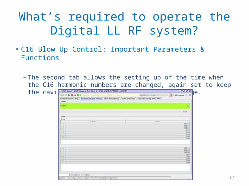
• C16 Blow Up Control: Important Parameters & Functions
– The second tab allows the setting up of the time when the C16 harmonic numbers are changed, again set to keep the cavity within it’s working frequency range.

18
What’s required to operate the Digital LL RF system?
• C16 Blow Up Control: Important Parameters & Functions
– The third tab allows the setting up of the C16 modulation and there are presently two modes of operation based around which of the two options have been selected in Frequency Offset Select (FOS).
– When FOS is set to Register, the Frequency Modulation knob Modulation Frequency sets the frequency, while the Modulation Depth the amplitude of the modulation. The frequency should be set to the synchrotron frequency (or a harmonic of it) at a point in the cycle where one has programmed C16 voltage, but there is inefficient blow up around this, often enough to achieve the blow up required.

19
What’s required to operate the Digital LL RF system?• C16 Blow Up Control: Important Parameters & Functions
– When FOS is set to Function, one has to ensure that function BAx.FGC16FS has been programmed with the appropriate synchrotron frequency function for the bunch shape and enabled. This should allow controlled longitudinal blow up that, due to resonance, is much more efficient, hence the duration of the programmed blow-up voltage shorter. In this case the Modulation Depth controls the amplitude of the modulation.

20
What’s required to operate the Digital LL RF system?
• C16 Blow Up Control : Signals to Observe– The C16 frequency can be observed on the
samplers as BAx.C16FREQ-SD to ensure it stays within the cavity limits.
– The C16 harmonic number changes can be observed on the samplers as BAx.C16HARM-SD, but one MUST program tab 4 (DSP C Simulator) of knob to have the same harmonic numbers as programmed on tab 1.
– The C16 modulation can also be observed on the Tomoscope or BSM as noise superimposed on the bunch.
– In the end, it’s the emittance measured at the end that counts.

21
What’s required to operate the Digital LL RF system?• Synchronisation Loop: Important Parameters &
Functions– The timing BEx.SFEJSYNC starts the extraction process at
C775.– The Extraction Synchronisation Phase Offset for each ring
can be found on the first page of the RF Synoptic. It’s also available via a complex knob BAx.DDC.B2, but this is one that will be simplified.
– The Extraction Frequency that is programmed on the Highland frequency synthesizer for synchronisation with ISOLDE or the dump can be found on knob BAx.DSPB or from the “Extraction reference” on the Extraction Synchro Frequency Steering synoptic and is typically 1746270Hz for H1 and 3492541Hz for H2. This will be the operational Extraction Reference from start up and there will be an update on this during the first week of operation in 2015.
– The Beating Frequency can also be found on knob BAx.DSPB or via the synoptic Extraction Synchro Frequency Steering and is typically 50-150Hz.

22
What’s required to operate the Digital LL RF system?• Synchronization Loop: Signals to Observe– The Synchro Loop response is best observed on OASIS with signal
BAx.SPL_PHASE-DS or global Extraction Synchro 2014 (will be updated for 2015!).
– The quality of trains BAX.TREV-AS, BAX.TRF-AS & BAX.TRFPSBSYNC-AS were improved by the OASIS team in 2014 and these remain available.

23
Work Underway• OASIS integration:
– We already have the analogue cavity drive signals available.– Bulk of work done for system signals, expect to see a small subset (~20) of
all the available signals(~200!) grouped by loop (Primary Phase Loop, Radial Loop etc) or process (Frequency Program) to make it simpler to find signals.
– We’ll generate Globals for each process/loop with the correct signals to help de-bug/fault find.
• Knob simplification & timing re-naming:– Started and expected before March 2015.
• Replacement of Pentek with Highland for extraction reference generator:– This will be integrated during the start-up in 2015, the Highland will be the
reference generator from now on.
24
Summary• The Digital LL is fully operational and the old system is
being de-commissioned.• We’ve shown how to find and adjust some of the
fundamental parameters and functions of the system.• We’ve shown how to observe some of the principal
signals with tools we have today, and hinted at what else should soon be available!
• There is still plenty to do to get the knobs, working sets and OASIS signals as requested, but work well underway.
• With the many projects each of the team members has been assigned, its not always easy to get enough of their precious time, so bear with us.

25
Thanks for staying awake!

26
Frequency Program Synoptic

27
Radial Loop Synoptic

28
Primary Phase Loop Synoptic

29
Secondary Phase Loop Synoptic

30
Extraction Synchronisation Frequency Steering Synoptic

31
Extraction Synchronisation Phase Loop Synoptic

32
C04 Phase Feedback Synoptic

33
C16 Blowup Block Diagram