provent systems plumbing...
TRANSCRIPT
Comparison of ProVent® Design Rules and The International Plumbing Code
ProVent Systems® Plumbing Fundamentals
Educational
Literature
Page 2 Copyright2007-2008 ProVent Systems. Inc
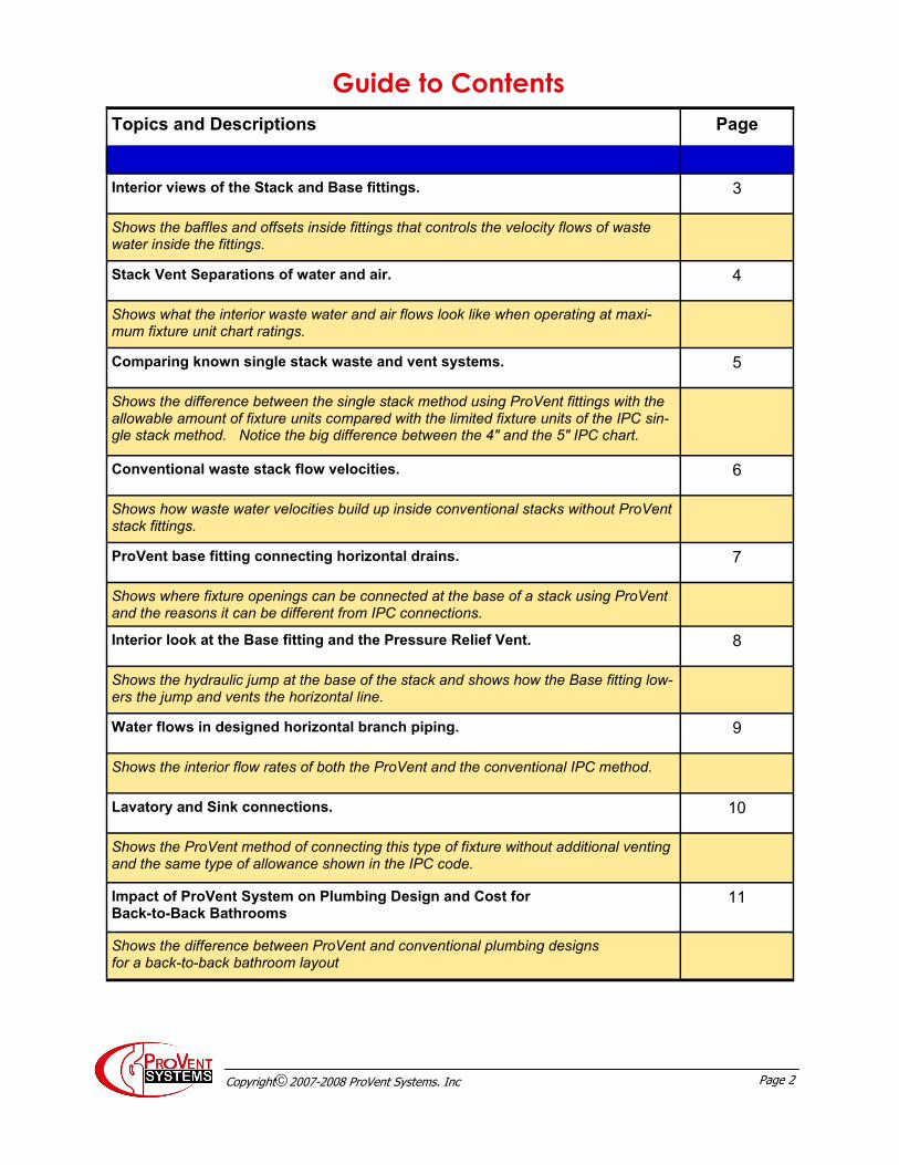
Topics and Descriptions Page
Interior views of the Stack and Base fittings. 3
Shows the baffles and offsets inside fittings that controls the velocity flows of waste water inside the fittings.
Stack Vent Separations of water and air. 4
Shows what the interior waste water and air flows look like when operating at maxi-mum fixture unit chart ratings.
Comparing known single stack waste and vent systems. 5
Shows the difference between the single stack method using ProVent fittings with the allowable amount of fixture units compared with the limited fixture units of the IPC sin-gle stack method. Notice the big difference between the 4" and the 5" IPC chart.
Conventional waste stack flow velocities. 6
Shows how waste water velocities build up inside conventional stacks without ProVent stack fittings.
ProVent base fitting connecting horizontal drains. 7
Shows where fixture openings can be connected at the base of a stack using ProVent and the reasons it can be different from IPC connections.
Interior look at the Base fitting and the Pressure Relief Vent. 8
Shows the hydraulic jump at the base of the stack and shows how the Base fitting low-ers the jump and vents the horizontal line.
Water flows in designed horizontal branch piping. 9
Shows the interior flow rates of both the ProVent and the conventional IPC method.
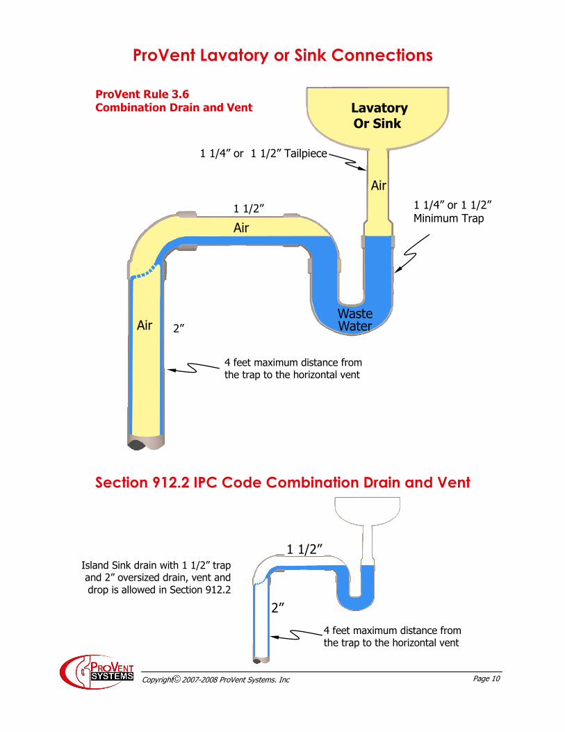
Lavatory and Sink connections. 10
Shows the ProVent method of connecting this type of fixture without additional venting and the same type of allowance shown in the IPC code.
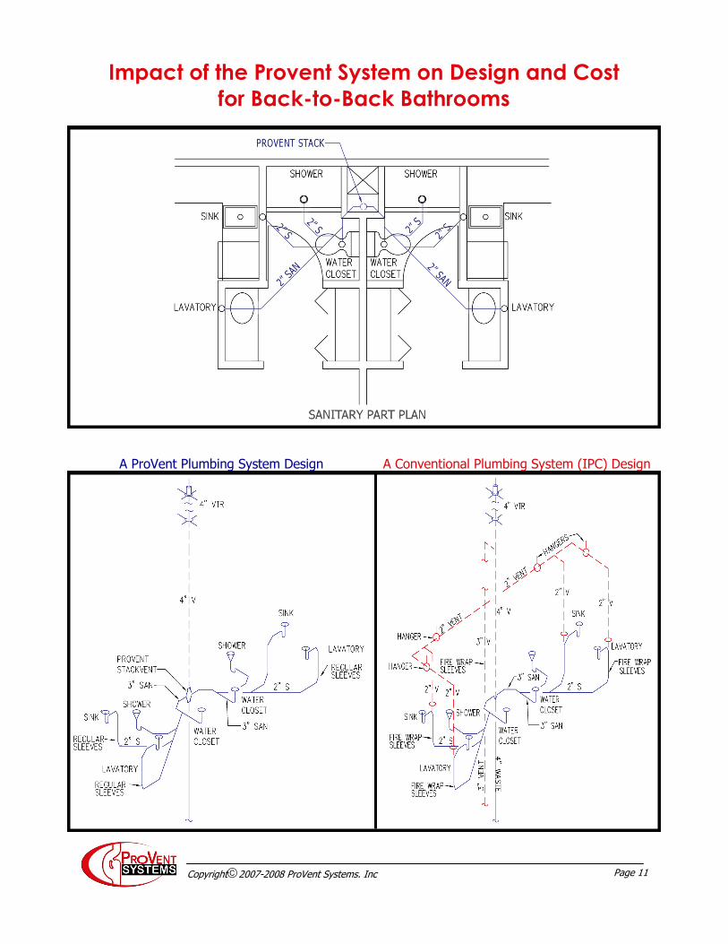
Impact of ProVent System on Plumbing Design and Cost for Back-to-Back Bathrooms
11
Shows the difference between ProVent and conventional plumbing designs for a back-to-back bathroom layout
Guide to Contents
Page 3 Copyright2007-2008 ProVent Systems. Inc
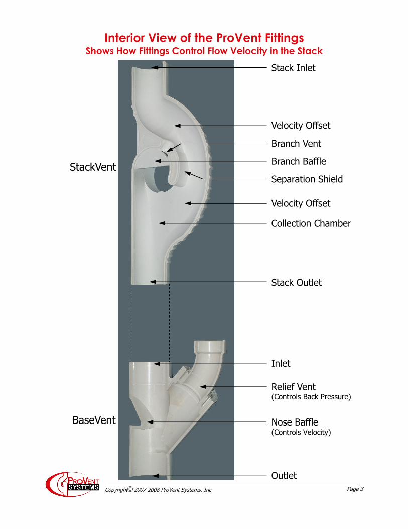
Stack Inlet
Branch Vent
Branch Baffle
Separation Shield
Collection Chamber
Stack Outlet
Inlet
Outlet
Nose Baffle (Controls Velocity)
Relief Vent (Controls Back Pressure)
StackVent
BaseVent
Velocity Offset
Velocity Offset
Interior View of the ProVent Fittings Shows How Fittings Control Flow Velocity in the Stack
Page 4 Copyright2007-2008 ProVent Systems. Inc
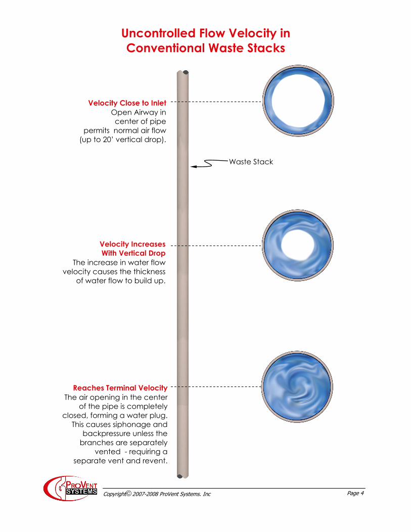
Uncontrolled Flow Velocity in
Conventional Waste Stacks
Velocity Close to Inlet
Open Airway in
center of pipe
permits normal air flow
(up to 20’ vertical drop).
Velocity Increases
With Vertical Drop
The increase in water flow
velocity causes the thickness
of water flow to build up.
Reaches Terminal Velocity
The air opening in the center
of the pipe is completely
closed, forming a water plug.
This causes siphonage and
backpressure unless the
branches are separately
vented - requiring a
separate vent and revent.
Waste Stack
Page 5 Copyright2007-2008 ProVent Systems. Inc
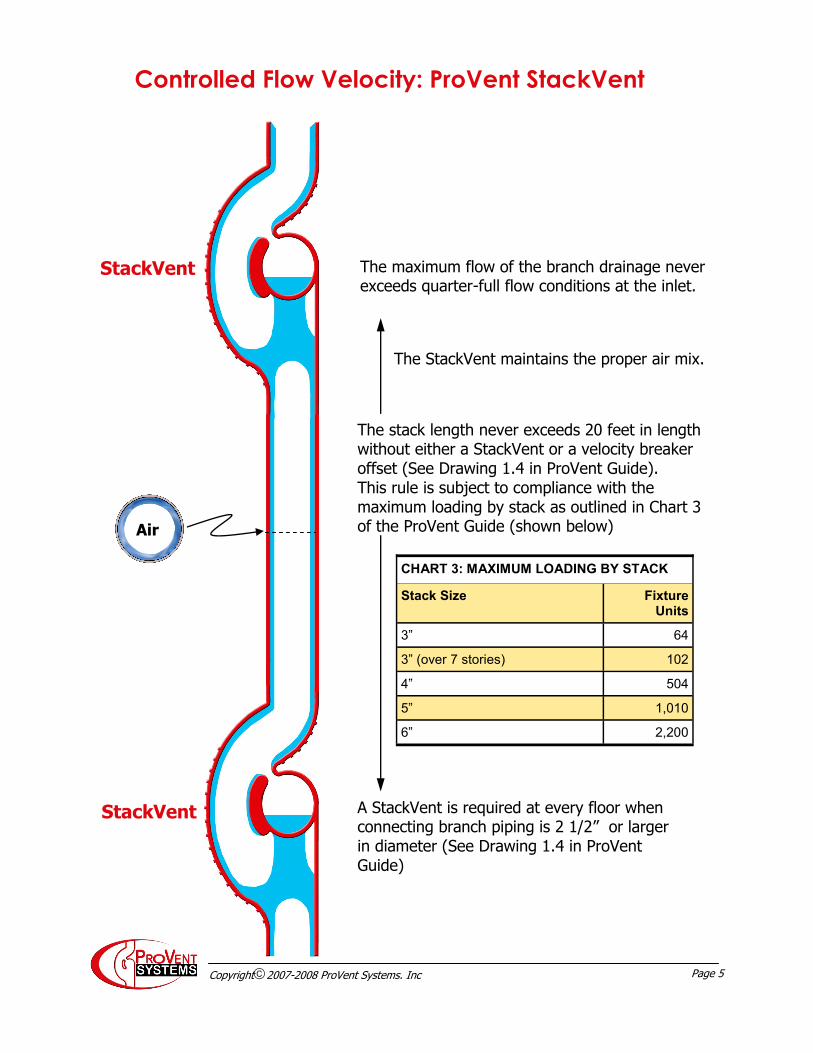
The maximum flow of the branch drainage never exceeds quarter-full flow conditions at the inlet.
The stack length never exceeds 20 feet in length without either a StackVent or a velocity breaker offset (See Drawing 1.4 in ProVent Guide). This rule is subject to compliance with the maximum loading by stack as outlined in Chart 3 of the ProVent Guide (shown below)
A StackVent is required at every floor when connecting branch piping is 2 1/2” or larger in diameter (See Drawing 1.4 in ProVent Guide)
CHART 3: MAXIMUM LOADING BY STACK
Stack Size Fixture Units
3” 64
3” (over 7 stories) 102
4” 504
5” 1,010
6” 2,200
Controlled Flow Velocity: ProVent StackVent
StackVent
StackVent
The StackVent maintains the proper air mix.
Air

Page 6 Copyright2007-2008 ProVent Systems. Inc
CHART 3: MAXIMUM LOADING BY STACK
Stack Size Fixture Units
3” 64
3” (over 7 stories) 102
4” 504
5” 1,010
6” 2,200
A StackVent fitting creates a combination drain and vent for fixtures. The chart below shows the Maximum Loading on the Stack. This is Chart 3 from the ProVent Guide. This type of system has been successfully used for over fifty years starting with Copper Sovent then Cast Iron Sovent and, now, PVC Plastic ProVent.
The comparison of the two charts, below, shows the dramatic increase in fixture loading for the ProVent System due to the controlled flow velocity.
ProVent PVC StackVent Fitting
The IPC “Waste StackVent”
The Waste StackVent is one of the terms used for classifying the stack as a combination drain and vent pipe system. This system has been identified by a variety of names including vertical vent, Philadelphia single stack and multiple floor stack venting and is included in the Interna-tional Plumbing Code, Section 910.
SIZE OF COMBINATION DRAIN AND VENT PIPE
MAXIMUM NUMBER OF DRAINAGE FIXTURE UNITS (dfu)
PIPE DIAMETER
Connecting to a hori-zontal branch or stack
Connecting to a building drain or building subdrain
2” 3 4
2 1/2” 6 26
3” 12 31
4” 20 50
5” 160 250
6” 360 575
Full Size Stack Vent Separate Connection to Stack (Double Sanitary Tee Permitted)
KS (TYP) KS (TYP)
Offsets Prohibited
Maintains Full Size Throughout its Length
IPC Chart 912.3
ProVent Chart
Controlling the flow velocities permits more fixture units to discharge into the combination waste and vent
Note the large difference in capacity
between the 4” and 6” stacks
Page 7 Copyright2007-2008 ProVent Systems. Inc
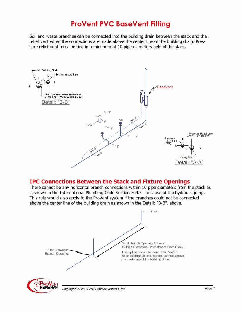
Detail: “A-A”
Detail: “B-B”
Soil and waste branches can be connected into the building drain between the stack and the relief vent when the connections are made above the center line of the building drain. Pres-sure relief vent must be tied in a minimum of 10 pipe diameters behind the stack.
IPC Connections Between the Stack and Fixture Openings
There cannot be any horizontal branch connections within 10 pipe diameters from the stack as is shown in the International Plumbing Code Section 704.3—because of the hydraulic jump. This rule would also apply to the ProVent system if the branches could not be connected above the center line of the building drain as shown in the Detail: “B-B”, above.
BaseVent
A
A
4” 3”
WC
1-1/2”
1-1/4”
LAV
2”
3”
B
B
*First Branch Opening At Least 10 Pipe Diameters Downstream From Stack
This option should be done with ProVent when the branch lines cannot connect above the centerline of the building drain.
Stack
ProVent PVC BaseVent Fitting
*First Allowable Branch Opening
Page 8 Copyright2007-2008 ProVent Systems. Inc
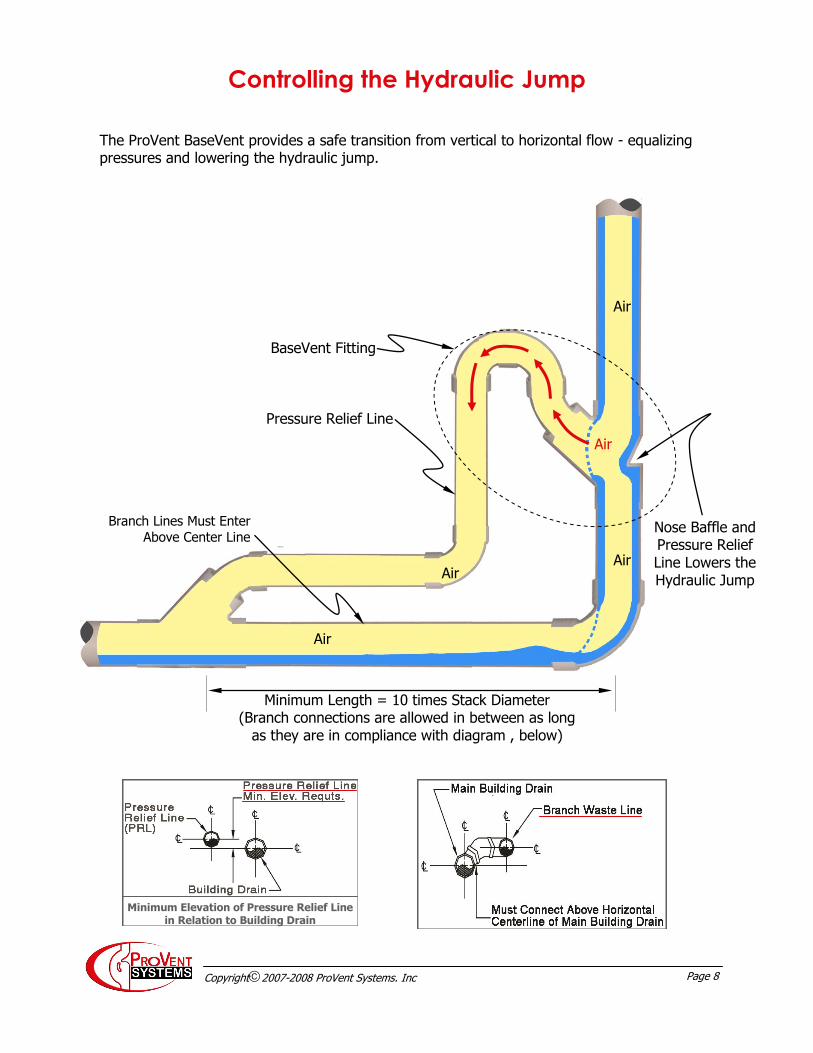
Controlling the Hydraulic Jump
Air
Air
Air
BaseVent Fitting
Pressure Relief Line
Nose Baffle and Pressure Relief Line Lowers the Hydraulic Jump
Minimum Length = 10 times Stack Diameter (Branch connections are allowed in between as long
as they are in compliance with diagram , below)
The ProVent BaseVent provides a safe transition from vertical to horizontal flow - equalizing pressures and lowering the hydraulic jump.
Air
Branch Lines Must Enter
Above Center Line
Minimum Elevation of Pressure Relief Line in Relation to Building Drain
Air
Page 9 Copyright2007-2008 ProVent Systems. Inc
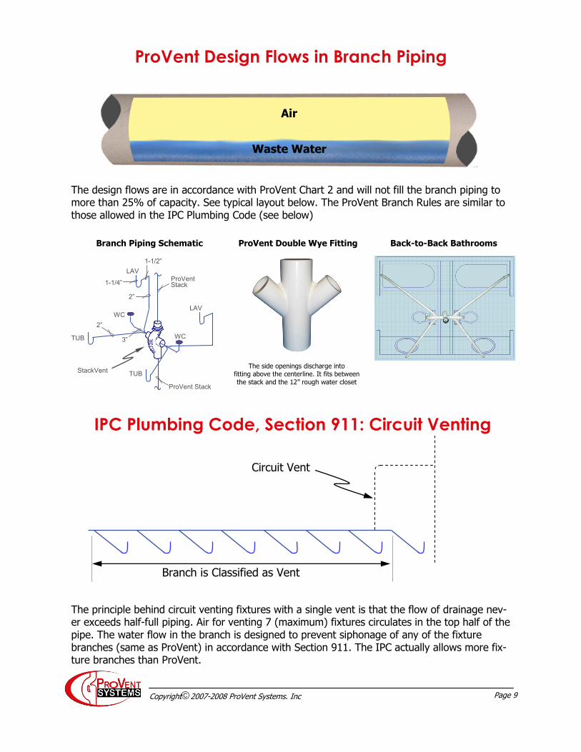
ProVent Design Flows in Branch Piping
The design flows are in accordance with ProVent Chart 2 and will not fill the branch piping to more than 25% of capacity. See typical layout below. The ProVent Branch Rules are similar to those allowed in the IPC Plumbing Code (see below)
Air
Waste Water
IPC Plumbing Code, Section 911: Circuit Venting
Branch is Classified as Vent
Circuit Vent
The principle behind circuit venting fixtures with a single vent is that the flow of drainage nev-er exceeds half-full piping. Air for venting 7 (maximum) fixtures circulates in the top half of the pipe. The water flow in the branch is designed to prevent siphonage of any of the fixture branches (same as ProVent) in accordance with Section 911. The IPC actually allows more fix-ture branches than ProVent.
WC
WC
TUB
3”
StackVent
ProVent Stack
ProVent Stack
2”
TUB
LAV
1-1/2”
1-1/4”
2”
LAV
The side openings discharge into fitting above the centerline. It fits between
the stack and the 12” rough water closet
ProVent Double Wye Fitting Branch Piping Schematic Back-to-Back Bathrooms
Page 10 Copyright2007-2008 ProVent Systems. Inc
ProVent Lavatory or Sink Connections
Section 912.2 IPC Code Combination Drain and Vent
1 1/2”
2”
Island Sink drain with 1 1/2” trap and 2” oversized drain, vent and drop is allowed in Section 912.2
Lavatory Or Sink
1 1/4” or 1 1/2” Tailpiece
Air
ProVent Rule 3.6 Combination Drain and Vent
Air
1 1/2” 1 1/4” or 1 1/2” Minimum Trap
Waste Water Air
4 feet maximum distance from the trap to the horizontal vent
2”
4 feet maximum distance from the trap to the horizontal vent
Page 11 Copyright2007-2008 ProVent Systems. Inc
Impact of the Provent System on Design and Cost
for Back-to-Back Bathrooms
A ProVent Plumbing System Design A Conventional Plumbing System (IPC) Design

Educational Literature
®