prototyping (3d) and model making
DESCRIPTION
Report DG619 - Prototyping (3D) and Model MakingTRANSCRIPT

Modeling a children’s motorcycleAssignment DG619 - Prototyping (3D) and Model Making
Jelmer de Maat

Assignment DG619 - Prototyping (3D) and Model Making
Teacher: Arjan Steketee
Jelmer de Maat / B2.2 Industrial Design / s099450
June 2011
In this report the process of designing and making a model of a children’s toy is described, as well as several other activities that have taken place in this assign-ment. In the end a vision on the future of model making is given.

4
Paper exerciseThe prototyping started with paper modeling:
making the strongest bridge possible from only
paper sheets, tape and glue, while using as less
of these materials as possible. I worked together
with Samantha on this particular assignment. To-
gether we made a bridge base from rolled paper
sheets that formed a pyramid construction. The
rolled cylinders rested on each other by making
use of incisions in the corners of the cylinders,
which prevented us from using more tapes. The
bridge part itself was made out of triangular
(alternately) folder paper sheets with a top and
a bottom paper sheet to keep them in place.
This bridge part was placed inside the pyramid
construction. We used little material (12 sheets
of paper, 15 pieces of tape and no glue at all) to
score as high as possible on the “bridge ranking”,
but unfortunately the bridge turned out to be not
sturdy at all. It didn’t hold one plastic bottle that
was filled with water for one fourth of the volume.
The connection points in the pyramid construc-
tion appeared to be too fragile.
Next to this I did the egg crash test: making a pa-
per model that could catch an egg, released high
above the ground, and prevent it from breaking. I
made a construction that consisted of rolled pa-
per sheets only. From bottom to top, the sheets
started rolled up small and sturdy, and ended
rolled up large and flexible. One sheet of paper
was used as a bottom plate. The reason for this
construction was the flexibility of large paper rolls,
and the transition to small rolls that provides sort
of a shock absorber. This construction proved
to work very well: not matter how high I would
let go of the egg, every time it remained intact. A
video of this egg crash test can be found here:
http://vimeo.com/24563619.
Clay exerciseIn the clay exercise I chose to make a model
of my mobile phone. Actually the model wasn’t
based on my phone but on my iPod, since that
form is way more interesting than that of my
phone. The hardest parts about modeling the
clay were to get the right angles and bends,
and getting the form symmetric across at least
two axes. The iPod shape doesn’t seem hard
to make, but it was difficult to get straight lines
and flat surfaces with clay: every little (accidental)
touch reshapes the clay. I see that this means
you can work very precisely with clay, creating
difficult complex shapes, while on the other hand
creating clean straight surfaces can be more
difficult. I found that clay in general was nice to
work with: it gave me freedom of form and a low
threshold to easily create complex shapes.
Base

5
Excursion Hoogerdijk Technical RubberAt Hoogerdijk Technical Rubber all kinds of rub-
ber and plastic solutions are made, mainly as
parts to implement in other products. Various
types of soft foams and hard plastics are pres-
ent and they can be used together to create a
special combination (a soft rubber and a hard
cover layer for example, or a thin rubber with a
sticky tape layer). All these materials can be very
useful in physical product designs: products that
are handheld may need soft covers for a pleas-
ant grip, or transport designs may need such
materials for seats. A children’s playground uses
all kinds of hard and soft plastic to both offer
stability and safety. I see possibilities here for my
future designs, and I will certainly keep a produc-
tion company like Hoogerdijk Technical Rubber in
mind when thinking about material solutions.
Excursion TNOThe Rapid Manufacturing department of the TNO
in Eindhoven is a professional quick prototyping
environment that makes use of the latest tech-
nologies such as 3D printing. They work together
with both students and companies. All the tech-
niques that are involved in rapid prototyping are
based on the same principle: building products
via the selective addition of material based on 3D
files made on the computer. I think the essence
of these techniques is the speed, the detail of
production and the reproducibility of products
and parts. A toy car like the one we saw at the
presentation, completely running on many little
rotating gears, can be produced in one go. No
need to assemble a product: the product parts
can be produced and assembled at the same
time.
Different techniques that we saw at the TNO have
different advantages and disadvantages. They
differ in the approach of production, the material
choice and costs, and a combination of these
factors must be taken into account when decid-
ing on which system to use. A good example is
SLS – Selective Laser Sintering. This technique
makes use of a platform with powder on top,
and a laser that draws a shape in the powder
from above. Then, the platform is moved down
just slightly, and new powder is spread smoothly
on top. Then the next layer of the product is
sketched on top, and the process repeats itself
The construction of the paper bridge Testing the strength of the bridge

6
an innovation driven education (and profession) I
think it is strange that our education provides little
opportunities and support for Rapid Prototyping.
We should be the early adopters and embrace
such technologies.
again and again. This way a product is build up
in layers. Other techniques work according to the
same principle.
A difference with for example Fused Deposition
Modeling (FDM) is that SLS uses a laser that
shapes the product, and FDM uses an extru-
sion head that supplies material from a cartridge.
Again the platform on which the product is build
moves down each time another layer is started.
With FDM however there is no support powder
in places where a shape overlaps air, or bends
outwards. Therefore support material is supplied
next to the build material to provide support for
instable parts.
Another technique is SLA – Stereo Lithography,
which is very similar to SLS, only this time a liquid
is used as a building material. In a vat with the
liquid the building platform moves down while a
laser melts layers of the product in the liquid. An
advantage of SLA is that very small parts can be
made (several millimeters or less). With all these
techniques it is necessary to remove the support
material afterwards: sometimes special liquid is
needed for this process.
With Rapid Prototyping, very complex products
and parts can easily be produced, also in larger
quantities. Products with working functionalities
can be produced right out of the machine. And,
very tiny parts can be produced with great ac-
curacy. It’s exciting technology, and I expect to
use it in the future to make sophisticated pro-
totypes. It’s my goal to at least test a rapid pro-
totyping technology during my bachelor here at
ID. I especially liked the open source 3D printer
project, and I would like to see those integrated
into our education soon. Since industrial design is
Mood board of existing motorcycles for children

7
As main project I chose to design and build the children’s toy, a multifunctional new toy that integrates two existing products in one: a toy car and a vacuum cleaner. The idea here was that while a kid would drive around in the house, the floor would be cleaned. The goal was of course to make a good looking, 1:1 form prototype using materials like wood and foam.
This project seemed way more interesting for me
than the other project, where one would make a
steering wheel handheld design for disabled peo-
ple. I have far more affinity with the user group of
children since I have experience in working with
them (as a trainer) outside the world of design. I
see it as an identification and consolidation of my
vision and identity as a designer to make such a
product: one that is helpful, functional and fun for
kids, thus helping two types of users (the parents
and the children).
Analysis, Idea generation & Concept develop-mentThe idea of a riding toy for children immediately
brought me the impression of a real transport
vehicle, only then sized down to make it an extra
small but realistic vehicle for children. It would be
very nice to have a toy that looked very real and
cool, giving the impression of a real vehicle so
children would feel proud of their “toy”. With that
thought in mind I started thinking about possible
shapes.
First I started sketching possible forms. I went
from cranes to airplanes and from rockets to
motorcycles. The crane and the airplane seemed
not safe enough because of the large parts they
would have outside of the vehicle (the arm of the
crane and the wings of the plane). These parts
could easily damage the house or create unsafe
situations for children. That’s how I came to the
rocket, since it has no wings. Still, a rocket with-
out any additional parts at was a cylinder and
looked way too little exciting for me. I added
small wings to make the de sign more interesting,
but it still gave an unsafe feeling.
Thinking of other possible “cool” vehicles with
which a kid could show off to his friends, I
thought of a motorcycle. A motorcycle has just
the right image for this children’s ride: a sign of
freedom and a “rebellious” character, a special
and personal item to the owner, but also enjoy-
able in groups. The motorcycle would be the
perfect idea.
I created a mood board which showed an analy-
sis of various motorcycle toys and bikes that
are created for children. Next to that I looked at
images of real motorcycles to get a feeling of how
Making a children’s toy

8
they were designed. Sketching existing and new
designs of motorcycles I tried to make a simple
yet compelling design. The design had to have
the “cool” feeling and be simple in its construc-
tion. It had to be as real as possible, and there-
fore all sketches were based on two-wheel mo-
torcycles, while in reality I knew that a children’s
ride would need three wheels to keep it stable.
Keeping all these details in mind, I created a
basic form that consisted out of only three parts:
a steering/fork part, a connection to the driving
wheel, and a seating that goes over into the rear
fender in one fluid line. Actually all parts consist
out of fluid lines: nice fluid curves in the material
that form the basic character of the motorcycle.
This simple but elegant solution was right ac-
cording to my ideas of a cool feeling and simple
design. The basic shape did change a few times:
sometimes to improve it and sometimes to ac-
count for production possibilities. The final design
consist of a straightforward, sturdy front fork,
a fluid connection to the driving wheel (which
needs to be doubled, to exist on both sides of
the two back wheels), and one thin and fluid
seating surface that runs from the front fork all
the way to the end of the rear fender.
As the motorcycle needed to be as real as possi-
ble, I chose for an existing and well known solu-
tion to attach the front fork to the chassis. With
two simple connection parts and one center axis
it is possible to attach the chassis with one hole
to the two main tubes of the front fork. Details
like such connections, and like the bended steer-
ing wheel, finish the design to make it stand out.
The motor has a friendly, yet strong look that
(hopefully) is very appealing for children.
First sketches of children’s rides
9
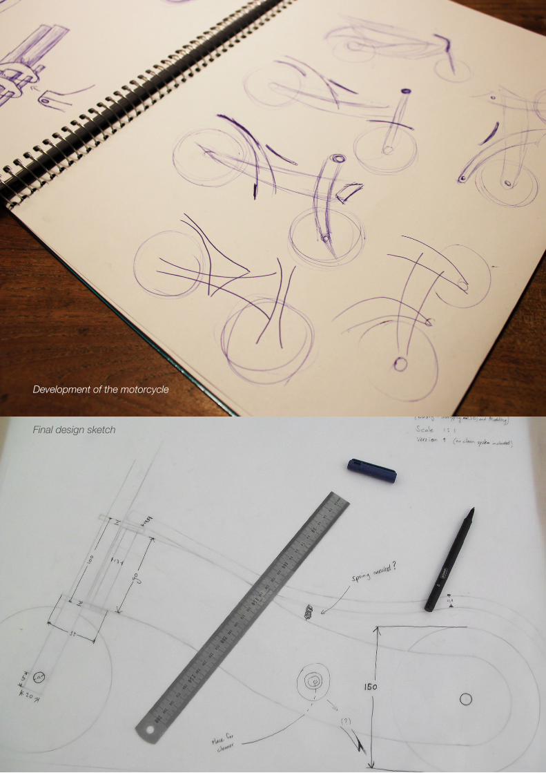
Final design sketch
Development of the motorcycle

10
Creating the modelAs can be seen on the mood board, many of
these children’s motorcycle rides are made from
wood. To me, this was also a first choice since
it has many advantages. Next to the friendly but
sturdy look of wood, it is also easy to process.
While my model does have complex bended
parts, it is still certainly not undoable with wood.
Wood is also friendly for kids: nicely sanded
wood removes sharp edges, and wood is rela-
tively soft when compared to metals or plastics.
Of course wood can be recycled easily which
makes it more nature friendly. And moreover the
wood gives the design the feeling it needs: sim-
ple, yet compelling.
The building process started with the parts ex-
pected to be the hardest: the bending of wood.
To get the fluid wooden lines in the design I
needed to find a solution to create a bended
piece of wood that was still sturdy enough to
carry a three year old kid, at least. Together with
the assignment teacher and a car model making
expert some options were explored. One option
is to first steam a plate of wood until it gets flex-
ible, then bring it into shape, and then let it dry.
This option would have needed some explora-
tion as it may not end up perfect after the first try.
Also, multiple plates of wood together might work
better than just one. It would give a nice smooth
surface though, something that would less easily
be achieved by the second technique: cutting a
lot of curve-shaped lines out of a thick piece of
wood and glue those together, horizontally one
after each another. This would give the perfect
curve, but the process takes longer and the end
result may not be as satisfying as a “real” piece of
curved wood. How I managed to do it in the end
is using a third technique: several layers of thin,
bendable wood are put into shape at the same
time, while they are glued together. A simple
mold that has the right curve is used to press the
layers of wood very strongly together. When the
glue is dry, the layers of wood stay go together in
the bended shape.
This way the bended seating part of the frame
was created. Due to time restrictions I wasn’t
able to make all the wooden bended parts: two
of the sustaining parts of the chassis are not
bend in the way I want. They do show the curve
in the vertical direction, which prevent the lack-
ing bend a bit from being quickly noticed. I chose
to bend the top surface since that was the eye-
catching and most important part for the charac-
ter of the design.
As said, the two sustaining parts of the chassis
are connected to the back wheel(s) via the back
wheel axis, which is made out of aluminum. This
axis is set up, as is always the case (and nec-
essary for the driving wheels to move straight),
perpendicular to the direction of the motor. Since
the two sustaining chassis parts are set up under
an angle to come together in one point at the
turning axis of the front fork, the holes for the rear
axis needed to be drilled under an angle as well.
When these two sustaining parts would actually
have been bend, the rear parts could have run
straight and this wouldn’t have been necessary.
The two rear wheels are fixed in place on the
axis by drilling holes next to their position in the
axis and putting some blocking material in these
holes.
Just like both the rear and front axis, the front
fork is made out of aluminum cylinders. I chose
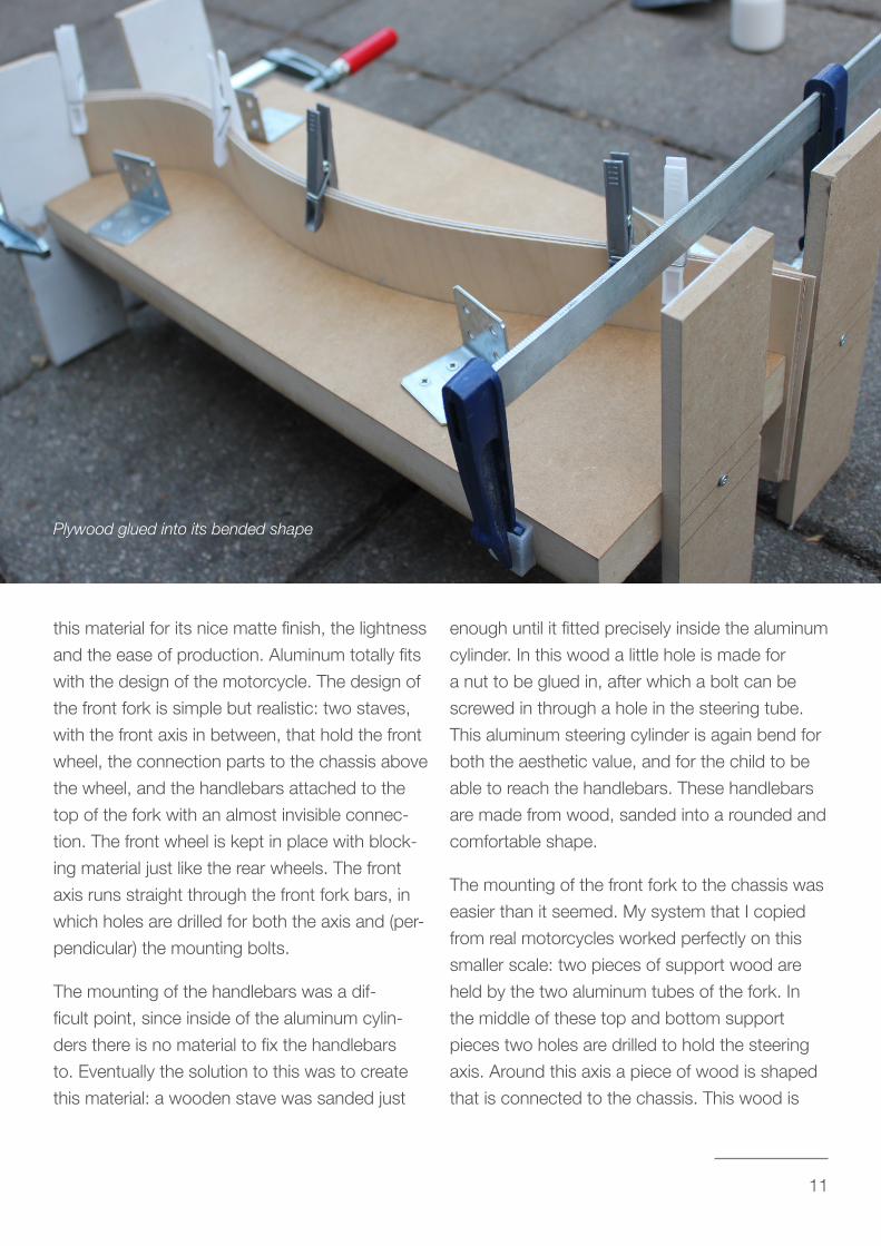
11
this material for its nice matte finish, the lightness
and the ease of production. Aluminum totally fits
with the design of the motorcycle. The design of
the front fork is simple but realistic: two staves,
with the front axis in between, that hold the front
wheel, the connection parts to the chassis above
the wheel, and the handlebars attached to the
top of the fork with an almost invisible connec-
tion. The front wheel is kept in place with block-
ing material just like the rear wheels. The front
axis runs straight through the front fork bars, in
which holes are drilled for both the axis and (per-
pendicular) the mounting bolts.
The mounting of the handlebars was a dif-
ficult point, since inside of the aluminum cylin-
ders there is no material to fix the handlebars
to. Eventually the solution to this was to create
this material: a wooden stave was sanded just
enough until it fitted precisely inside the aluminum
cylinder. In this wood a little hole is made for
a nut to be glued in, after which a bolt can be
screwed in through a hole in the steering tube.
This aluminum steering cylinder is again bend for
both the aesthetic value, and for the child to be
able to reach the handlebars. These handlebars
are made from wood, sanded into a rounded and
comfortable shape.
The mounting of the front fork to the chassis was
easier than it seemed. My system that I copied
from real motorcycles worked perfectly on this
smaller scale: two pieces of support wood are
held by the two aluminum tubes of the fork. In
the middle of these top and bottom support
pieces two holes are drilled to hold the steering
axis. Around this axis a piece of wood is shaped
that is connected to the chassis. This wood is
Plywood glued into its bended shape

12
shaped is such a way that it seamlessly connects
to the two support parts of the chassis.
Lastly, the seating part had to be connected to
the frame. This is done using a small piece of
connection wood in between the two support
pieces of the chassis. This connection piece is
the only point of connection between the seat
and the frame: simple yet solid. It also allows for
the seating to have a natural suspension prop-
erty. In the front the seat plate slightly hovers the
chassis connection to allow for a larger steering
angle. In the back the seat plate hovers over the
back wheels freely.
After all the parts were produced, some sand-
ing was done on all the wooden parts to finalize
them, and minor corrections were executed to
tweak the bike into its last and best state.
During the making of the model I continuously
kept the qualities of the design in mind. I had to
find solutions for connections of parts very of-
ten, and I made decisions mainly based on the
aesthetic value and the physical quality of the
solution. The design had to be simple yet cool,
and so no complicated parts or connection can
be seen on the outside of the model. A bolt and
a nut is the most you can discover as a connec-
tion unit, nothing more than that. This is part of
the beauty of the design: you can see the “inner
workings”, and there is no need to try and cover
A motorcycle coming together
13
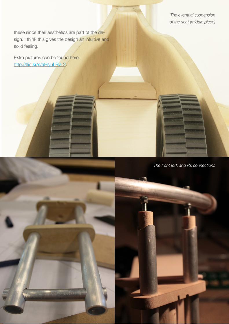
these since their aesthetics are part of the de-
sign. I think this gives the design an intuitive and
solid feeling.
Extra pictures can be found here:
http://flic.kr/s/aHsjuLBvL2.
The front fork and iits connections
The eventual suspension
of the seat (middle piece)

14
Reflection / Future of model making
The introduction of this assignment was to work
with paper and clay. I experimented with these
materials to create bridges and clay models of
my phone. Though we spent little time on these
assignments I think it was a good introduction
to the assignment to get a feeling for material.
Especially the clay modeling seems to me im-
portant, as I can relate it better to product de-
sign than the paper experiments. I never worked
with clay before to create models, but I liked the
creativity that you can put into the clay forms. It
was difficult to work with when making smooth
surfaces, but it’s more important that it gives a lot
of room for experimentation. When designing a
handheld object, for example, many explorations
can be done to design a comfortable object. I
will use clay more often from now on, especially
when designing smaller (handheld) products.
Designing and building the children’s motorcycle
gave me new knowledge and new skills. Espe-
cially during the concept development I noticed
that I picked up a lot from sketching out ideas. It
was very helpful to have some example images
of real motorcycles as a basis, and look at exist-
ing products for children to catch up on what’s
already on the market. I took specific parts from
all the examples and made new sketches with
combinations of these aspects. Sometimes I
completely dumped an idea when it didn’t satisfy
me eventually.
The process to the final design was quite long,
but when I look back I see that it was worth it. I
went from one design to another, and I really feel
like the final design was indeed the best. It was
hard to separate the good from the bad when
it came to specific design details: sometimes I
would have liked to implement more things or
tried out several options first. But I chose one
design and completely focused on getting that
one done as good as possible, also due to time
restrictions.
Through I am really satisfied with the result, some
things could have been improved. For example
multiple parts of the frame should have been
bent (and not only the seat plate). Next to that
the wooden parts I used to connect the frame to
the fork could have been improved. These and
other parts of the bike didn’t use the same wood,
so the color difference was quite big. The color
of the total bike would have been the color of the
seating plate, the color of the sanded plywood: a
light and clear wood color. This color combines
great with the clear matte grey of the aluminum. I
would also have liked to put custom tires on the
bike. The tires used in the current model are the
most suitable tires I could find in hardware stores
nearby, but they were quite general. The real
wheels should have had real metallic rims and
15
black tires filled with air instead of plastic. Though
the ones I used now aren’t bad, this would really
have improved the look of the motorcycle.
What I learned from building the motorcycle are
mainly producing techniques and experience
in working with wood and metal. I learned for
example several methods of creating bended
wooden parts, and I learned about the proper-
ties of aluminum and how you can process this
metal. I didn’t know aluminum was so easily to
process, for example with regular drills and saws.
I’m sure I’ll try out more with this material in future
projects. Next to that I had to be creative in find-
ing the right materials in the right places. In fact
the workshop in Vertigo has very limited possibili-
ties in materials, but I only realized this with this
assignment. Having built many prototypes there
in the past I have now seen and tried out most
of what is possible in Vertigo, and now I realized
that I want to experiment with custom materials,
to make more specialized prototypes. Next to
that it would be good to try out new techniques
that aren’t available in Vertigo, like milling 3D
printing.
This Rapid Manufacturing we have seen at the
TNO was very interesting. There are so many
possibilities with all the different techniques and
so many things can be created in great detail. It
was exciting to see what can be done: complex
shapes, working mechanics, home-made open-
source 3D printers for “just” 1000 euro’s… This
technology is going to be a standard in our world
some time. Being able to manufacture a design
from behind a computer with a 3D file is nowa-
days a possibility for students to create a fine-
tuned prototype, but in the future it will also be
available for home users that want to print a new
part for a broken vacuum cleaner. As said, I think
that we as Industrial Design at the TU/e should
be handling these techniques with a far more
progressive approach. Set up plans, projects,
maybe themes that focus on such technology. As
an innovative faculty there need to be innovative
techniques widely available for all students.
Of course, while these rapid prototyping tech-
niques are great, I think they are not going to
replace traditional, physical hand modeling. Just
like traditional newspapers will exist next to the
iPad. Designers and companies just need to find
the right approach to bring these two sides of
design together in a good way: the one does not
have to exclude the other. Things like clay mod-
eling and sketching are necessary to be creative
and explore possibilities. Computers are way too
constraining in that sense: at least you can make
creative mistakes and take side-routes when you
are freely designing with your hands. Finding the
balance between these two fields is maybe going
to take a long time, but I think hand modeling
and rapid prototyping will both find their place
more or less automatically. Real designers will
know what to use when. Maybe some time in
the future, hand modeling and rapid prototyping
will even be integrated and fall under one and the
same name… but that’s just speculations.
As a last remark I would like to advice the assign-
ment teacher to provide more guidance when
it comes to getting a feeling for materials. We
only shortly addressed paper and clay modeling,
and then went over to a final prototype quickly.
It would have been interesting to see for exam-
ple more use cases and best practices about

16
working with clay: maybe one or two days could
entirely be dedicated to creating forms with clay?
More time would then be spent on (making)
specific forms and shapes. Then, the core of the
assignment would be addressed more: getting
a feeling for materials and model making. This
would also improve the thinking about forms and
shapes in general, to get a better understanding
of aesthetics and beauty as a whole.