protégé - allen organ company · orchestral instrument; for example, an imitative “violin...
TRANSCRIPT

1
Protégé ™Theatre Organs
C-19c and Protégé Theatre Compact
Copyright © 2003 Allen Organ CompanyAll Rights Reserved
AOC P/N 033-00084 Revised 5/27/03
ALLEN ORGAN COMPANY
2
For more than sixty years--practically the entire history of electronic organs-- Allen OrganCompany has built the finest organs that technology would allow.In 1939, Allen built and marketed the world’s first electronic oscillator organ. The tonegenerators for this instrument used two hundred forty-four vacuum tubes, contained aboutfive thousand components, and weighed nearly three hundred pounds. Even with all thisequipment, the specification included relatively few stops.
By 1959, Allen had replaced vacuum tubes in oscillator organs with transistors. Thousandsof transistorized instruments were built, including some of the largest, most sophisticatedoscillator organs ever designed.
Only a radical technological breakthrough could improve upon the performance of Allen’soscillator organs. Such a breakthrough came in conjunction with the United States SpaceProgram in the form of highly advanced digital microcircuits. In 1971, Allen produced andsold the world’s first musical instrument utilizing digitally sampled voices!
Your organ is significantly advanced since the first generation Allen digital instrument.Organs with Renaissance technology are the product of years of advancements in digitalsound and control techniques by Allen Organ Company. This system represents the apex ofdigital technology applied to exacting musical tasks. The result is a musical instrument ofremarkably advanced tone quality and performance.
Congratulations on the purchase of your new Allen Organ! You have acquired the mostadvanced electronic organ ever built, one that harnesses a sophisticated custom computersystem to create and control beautiful organ sound. Familiarize yourself with the instrumentby reading through this booklet.
ContentsI. Description of Stops .......................................................................................................3
II. Tremulants......................................................................................................................4
III. Expression Pedal ............................................................................................................4
IV. Capture Combination Action..........................................................................................4
V. Transposer ......................................................................................................................5
VI. Artistic Registrations ......................................................................................................5
VII. Virtual Acoustics™........................................................................................................7
VIII. Installation, Voicing and Care of the Organ...................................................................7
IX. Safety Instructions ..........................................................................................................9
X. MIDI Guide ..................................................................................................................10
XI. Console Controller Guide.............................................................................................15
3
I. DESCRIPTION OF STOPSPITCH FOOTAGEThe number appearing on each stop along with its name indicates the “pitch” or“register” of the particular stop. It is characteristic of the organ that notes of differentpitches may be sounded from a single playing key. When this sound corresponds to theactual pitch of the playing key, the note (or stop) is referred to as being of 8’ pitch;therefore, when an 8’ stop is selected and middle C is depressed, the pitch heard will bemiddle C. If it sounds an octave higher, it is called 4’ or octave pitch. If it sounds twooctaves higher, it is called 2’ pitch. Likewise, a 16’ stop sounds an octave lower, and a32’ stop sounds two octaves lower.
Stops of 16’, 8’, 4’, and 2’all have octave relationships, that is, these “even numbered”stops all sound octaves of whatever key is depressed. Pitches other than octaves are alsoused in organ playing. Their footage number always contains a fraction (i.e., 2 2/3, 13/5), and they are referred to as mutations. Because they introduce unusual pitchrelationships with respect to the fundamental tone, they are most effective whencombined with other stops, and are used either in solo passages or in small ensembles.
TONAL FAMILIESOrgan tones divide into two main categories: flues and reeds. In a pipe organ, flue pipesare those in which the sound is set in motion by wind striking directly on the edge of themouth of the pipe. Flues include diapason tones, flute tones, and string tones.Compound stops and hybrid stops are “variations” within these three families.
The term “imitative” means that the organ stop imitates the sound of the correspondingorchestral instrument; for example, an imitative “Violin 8’” would be a stop voiced tosound like an orchestral violin.
In reed pipes, a metal tongue vibrates against an opening in the side of a metal tube calleda shallot. The characteristic sounds of different reeds are produced through resonators ofdifferent shapes.
Your Protégé Chamber Series™ Allen Theatre Organ provides authentic examples ofvarious types of voices as listed above. Some of these are protected by copyrights ownedby the Allen Organ Company. The voices stored in memory are covered by United Statescopyright laws, pursuant to Title 17 of the United States Code, Section 101 et seq.
UNIFICATIONIn theatre organs, and occasionally in classical organs, the system of “unification” wasused. This allowed the same “rank” of pipes to be used at multiple pitches and on severalmanuals. Unification was the system theatre organs used to have large numbers of stopson the console with relatively few ranks of pipes as compared to a classical organ. Forexample, a Tibia Clausa rank may be drawn at 16’, 8’, 4’, 2 2/3’, 2’, and 1 3/5’ on a givenmanual and then still have some or all of those pitches duplicated on other manuals. Inmost classical organs, one rank would have one stop key on the console; however, in atheatre organ one rank could have many stop keys controlling it. Allen Theatre Organsare unified in the authentic theatre organ style.

4
Following is a discussion of individual ranks of the organ.‘D’ Trumpet Very imitative trumpet stop found on the style ‘D’
Wurlitzer theatre pipe organ.
Open Diapason Foundation stop that adds fullness to ensemble. The 16’stop is usually called “Diaphone” because bottom octave ofthe 16’ is a metal Diaphone sound. This lends power andgood pitch sense to the pedal.
Tibia Clausa The “foundation” rank of the theatre organ. This rank,coupled with its distinctive tremulant, is one of the mainingredients of a theatre organ.
Clarinet Imitative solo reed can also be used as an ensemble stop.
Violins II Two string tones slightly detuned from each other thatcreate a shimmering quality in the sound.
Orchestral Oboe Solo reed with a pungent nasal timbre somewhat imitativeof its orchestral counterpart.
Vox Humana Voice originally intended to imitate the human singingvoice but really sound more like a goat! Used with theTibia Clausa for the traditional theatre organ sound.
Concert Flute Typical wood open flute of the 1920’s, and used foraccompaniment.
Chimes, Glockenspiel,Chrysoglott, and the Cymbal Imitative of their orchestral counterparts.
II. TREMULANTSYour Protégé theatre organ has the most advanced authentic sounding tremulant systemavailable. In addition to digitally sampling individual ranks without tremulant, Allen alsosamples individual ranks with tremulants on. When more than one rank is on the sametremulant system in a pipe organ, the tremulant sound from the playing the pipes is notidentical from rank to rank. Each rank “reacts” to the varying supply of wind (tremulant)differently. Similarly, Allen sampled each rank of the organ with tremulant “on” toreproduce the authentic tremulant sound you hear. Even stops that are “ganged” togetheron one tremulant stop or tremulant motor will have a different tremulant sound. ThisSampled Waveform Tremulant™ technology contributes to the huge ensemble sound ofthe organ.
III. EXPRESSION PEDALThe Protégé Theatre Organ has one general expression pedal for the entire organ.
IV. CAPTURE COMBINATION ACTIONYour organ is equipped with an Allen multi-memory capture action, which offers theultimate in registration control and convenience. The organist can set combinations onany memory and then lock the memory (except memory 1 that cannot be locked). This
5
prevents unwanted tampering with capture combinations. See the Console Controller™instruction booklet later on in this manual regarding the setting of pistons.
THINGS TO REMEMBERThe “R” Piston, when activated, will recall the last combination set prior to using anygeneral or divisional piston. General pistons affect all stops. Solo and Accompanimentpistons affect only stops in their division.
All pistons operate independently from each other. However, the capture action is notfully operable until approximately six seconds after the organ is turned on. Furtherinformation on setting, changing, and reconfiguration of pistons will be found in theConsole Controller section of this manual.
V. TRANSPOSERThe Console Controller controls operation of the transposer. To raise or lower the musicto a higher key, perform the following steps.
1. Press the cursor key twice (a box will illuminate around the large “0” in lower rightcorner of the window). When the zero is displayed, the organ is in neutral position.
2. The organ’s pitch is now ready to be adjusted in half-step increments. Transposerwill allow organist to raise pitch of organ up to 5 half steps, or down 7 half-steps.
3. To raise the pitch of the organ:With Controller displaying a “0” in the illuminated box, rotate the knob clockwiseuntil a “1” is displayed in the illuminated box. The organ has now been raised onehalf step. Rotating the knob clockwise until a “2” is displayed in the box will causethe organ’s pitch to be raised two half steps. Each advancement of the number (upto and including number 5) will raise the organ one half step. Note: When theorgan’s pitch is altered by the transposer, the red LED will be illuminated.
4. To lower the pitch of the organ:With the Controller displaying a “0” in the illuminated box, rotate the knob counter-clockwise until a “-1” is displayed in the illuminated box. The organ has now beenlowered one half step. Rotating the knob counter-clockwise until a “-2” isdisplayed in the box will cause the organ’s pitch to be lowered two half steps. Eachadvancement of the number (up to and including number –7) will lower the pitch ofthe organ one half step. Note: When the organ’s pitch is altered by thetransposer, the red LED will be illuminated.
5. To return the pitch of the organ to the neutral position:Rotate the dial until a “0” is displayed in the illuminated box. Press the cursorbutton once so that the large illuminated box disappears. The organ is now lockedin the neutral position, and the red LED transposer light will no longer beilluminated.
Note: If organ is powered off, transposer will automatically return to neutral position.
VI. ARTISTIC REGISTRATIONOrgan registrations fall into two broad categories: solo combinations and ensembles.

6
SoloA solo combination is one in which a melody is played on one keyboard, theaccompaniment on another keyboard, and the pedal often provides a light bass line.Almost any stop or combination of stops will sound good as a solo voice. A contrastingtone quality should be chosen for the accompaniment, so that the accompaniment is softerthan the solo voice. The Pedal stops must provide a foundation for the sound withoutcovering it. Caution is advised when the solo part involves chords, since some stops donot blend well in close harmony. Avoid fractionally pitched (mutated) stops and pungentsounding reeds unless they produce the effect you are seeking.
Most 8’ reed stops make interesting solo voices. The addition of a 4’ Tibia or a Tibiamutation (e.g., Twelfth or Tierce) to a light reed such as the Clarinet or Orchestral Oboecolors the sound further and increases its volume slightly. Adding an 8’ Tibia to a reedwill add body to the sound.
In creating registrations of your own, remember these three simple rules: (1) Seek tonalcontrast between solo and accompaniment; (2) Be sure the solo is louder than theaccompaniment; (3) Choose a solo whose character is appropriate to the specific piece.
ENSEMBLEEnsemble registrations involve groups of stops that are played together, usually, but notalways, with both hands on one keyboard. They are characterized by compatibility oftone, clarity, and occasionally power. Volumes have been written on the subject ofensemble registration. Following is a summary of the major points.
Ensembles are created by combining stops. Two factors are always to be considered:tone quality and pitch. Ensembles begin with a few stops at the 16’, 8’, and/or 4’ pitchand expand “outward” in pitch as they build up.
Ensembles are generally divided into three tonal groupings or “choruses”:
The Tibia Clausa chorus is the most fully developed with representation invarious divisions of the organ and at every pitch from 16’ (Tibia) through 1 3/5’(Tierce). Lighter stops can be added to the basic 8’ and 4’ Tibia combinationsand then the Diapasons, Strings and Trumpets can be added to fill out anensemble registration.
The Reed stops include those reed tones designed to be used in the ensemblebuildup. Not all reed voices are ensemble tones. An Oboe, for example, isusually a solo stop. The various Trumpets, Horns, and Vox Humanas areusually ensemble voices that add brilliance, power, and incisiveness to thesound. If you have questions as to whether a specific reed is a solo or ensemblestop, refer to the stop glossary in the preceding section.
The Pedal ensemble is created in much the same way as the manual ensembles,with the Pedal starting at 16’ pitch instead of 8’. Be careful that the volume ofthe pedals is not greater than that of the manuals. Although the manual to pedalcouplers are useful in bringing clarity to the pedal line, especially on softerregistrations, avoid the temptation to rely constantly on one or two 16’ stops anda coupler. Many times in more rhythmic pieces you will want to have apredominantly 8’ sound in the pedal.

7
This short treatment barely scratches the surface of the fascinating subject of organregistration. For those interested in gaining further insight into this vital area of organplaying, we recommend the following texts:
Theatre Organ Registration:Strony, Walter. Theater Organ Registration $35.00
Classical/General Organ Registration:Audsley, George Ashdown. Organ Stops and their Artistic Registration.
Hialeah, FL: CPP Belwin, 1985Irwin, Stevens. Dictionary of Pipe Organ Stops. 2nd Ed.
New York: Macmillan Books, 1983.
Beginning Organist’s Video:Cherrington, Dr. Sally. A Church Organist’s Primer. Volumes I, II, & III
Allen Organ Company. Video Materials, 1998/1997AOC P/N: 031-0047, 031-0065, 031-0012.
VII. VIRTUAL ACOUSTICS SETTINGSVirtual Acoustics™ provides the spatial ambiance of reverberant rooms of various sizes.Although most effective in poor (non-reverberant) acoustic environments, it enhances thesound even in optimal acoustic settings.
There are 21 selectable reverb pallets. One of these, the DEFAULT setting, is notadjustable. The other 20 pallets are selectable and adjustable. They allow an organist tomodify the sound of the organ to accommodate a room’s changing acoustical properties.For example, a room’s reverberation characteristics change as the number of peoplepresent changes. Differences in reverberation time also occur when a room’s windowsare opened or closed.
The rocker switch labeled VIRTUAL ACOUSTICS™ in the Console Controller must beON to hear the selected reverb. The amount of reverb can be changed on the 20adjustable selections. The selected reverb level, measured in dB (decibels), is shown inthe Console Controller™ window. The range of control is from Ø dB to -3Ø dB. Minus3Ø dB is the least amount of reverb; Ø dB is the most reverb available. When youchange the Virtual Acoustics™ setting, you must turn the rocker switch OFF and ONagain for the new setting to take effect.
VIII. INSTALLATION, VOICING, AND CARE OF THE ORGANINSTALLATION
Wherever your Protégé Theatre Organ may be situated, careful installation is aprerequisite to achieving successful results. Your Allen representative is well qualified toguide you in planning for this. Allen Organ Company factory assistance with planningthe installation is available and may be sought by your local Allen representative. Oncethe organ is installed, be mindful of changes made to the room it is located in. Care mustbe taken to insure that when acoustical changes occur, your Allen Organ representative isnotified.

8
VOICINGThe organ presents unprecedented accuracy in the scaling and voicing of each note ofevery stop. Should your needs be such that these parameters need to be changed, yourAllen Organ representative is able to help make these changes. This musicalbreakthrough is an inherent part of the engineering design of the instrument. Finaladjustments in scaling and voicing involve procedures that are best left to an expert.These adjustments are normally a part of installation and, once done, should not requirechanges. If the instrument is moved to a new location or major changes are made to theacoustical properties of the room the organ resides in, the instrument may need to betonally finished again.
Your Allen Organ not only faithfully reproduces the organ traditions of the past but alsoanticipates the innovations of the future. Should you have questions that are notaddressed in this manual, please do not hesitate to contact your local Allen Organrepresentative. Welcome to the family of satisfied Allen Organ owners!
BATTERY BACKUP SYSTEMThe memory for the capture system on your Chamber Series™ Organ is sustained by aLithium battery. This allows capture settings and related items to be retained in memorywhen the organ is switched off or unplugged. Under normal circumstances, the Lithiumbattery should last for several years. A built-in warning system will alert you when thebattery becomes weak and needs to be replaced. Have the Console Controller™ openbefore the organ is turned on. If there is a problem the window will display for about sixseconds after the organ is switched on.:
Power FailureREPLACE
BATTERY !
Should the battery in your Chamber Series™ organ require replacement, contact your localauthorized Allen Organ service representative.
CLEANING AND POLISHINGYour Allen Organ constitutes a major advance in long-term maintenance-free operation.There are no regular maintenance procedures required and, therefore, no periodicmaintenance schedules to be observed. Reasonable care will keep the instrument lookingbeautiful for years to come. The wood surfaces may be cleaned using a soft clothdampened with lukewarm water. A mild solution of lukewarm water and furniture soapmay be used to remove fingerprints, etc. Polish dry with a soft cloth.
Do not use wax, sprays or oils on the finish. Satin finished surfaces will take on a semi-gloss appearance when waxed and will eventually become yellowed. If you need to“polish” the organ for a special event, use only a very high quality wood furniture polish.Keys and stops should be cleaned using two clean cloths. Immerse one in clear,lukewarm water and wring it thoroughly damp dry. Loosen the dirt with this cloth, thenpolish with the dry cloth. Do not use soap or detergent on the keys or stops. Do not usewax, sprays or oils on the finish. Satin finished surfaces will take on a semi-glossappearance when waxed and will eventually become yellowed. Keys and rocker stopsshould be cleaned using two clean cloths. Immerse one in clear, lukewarm water and
9
wring it thoroughly damp dry. Loosen the dirt with this cloth, and then polishimmediately with the dry cloth. Do not use soap or detergent on keys or rocker stops.
You have purchased a remarkable organ that not only faithfully reproduces the organtraditions of the past but also anticipates the innovations of the future. Should you havequestions that are not addressed in this manual, please do not hesitate to contact yourlocal Allen Organ representative. Welcome to the family of satisfied Allen Organowners!
IX. SAFETY
CAUTIONDo not plug the instrument into any current source other than 105-128 volts,50/60-Hertz alternating current (AC). A verified-grounded outlet is essential toproper operation and protection of the instrument. Proper polarity should bechecked with an AC circuit analyzer before connecting the organ.Do not change the cable plug or remove the ground pin or connect with a two-poleadapter.If you are in doubt about your electrical connection, consult your local electricianor electrical power company.In churches where circuit breakers are turned off between worship services, thecircuit breaker affecting the organ console AC power should have a guard installedto prevent its being accidentally switched off.Read and comply with all instructions and labels that may be attached to theinstrument.
Warning: This equipment generates, uses, and can radiate radio frequency energyand, if not installed and used in accordance with the instruction manual, may causeinterference to radio communications. It has been type tested and found to complywith the limits for a Class B Computing Device in accordance with thespecifications in Subpart J of Part 15 of FCC Rules, which are designed to providereasonable protection against such interference in a residential installation. Shouldthis equipment cause interference to radio communications, the user at his ownexpense will be required to take whatever measures may be necessary to correctthe interference. Whether this equipment actually causes the interference to radiocommunications can be determined by turning the equipment off and on. The useris encouraged to attempt to correct the interference by one or more of thefollowing measures:• Reorient the receiving antenna.• Relocate the organ with respect to the receiver.• Move the organ away from the receiver.• Plug the organ into a different electrical outlet, so that the organ and receiver
are on different branch circuits.If necessary, the user should consult the dealer or an experienced radio technicianfor additional suggestions.

10
X. MIDI GUIDE FOR ORGANISTS
WHAT IS MIDI?
The term MIDI is an acronym for Musical Instrument Digital Interface and is nothingmore than a communications system. MIDI has been adopted by the music industry as astandard means of communication between musical devices. MIDI enables devices ofdifferent types and manufacturers to easily communicate with each other. It is notnecessary to understand all of the technical aspects of MIDI in order to take advantage ofits benefits. It is important to explore the potential MIDI holds for musicians, as well asthe various MIDI applications available today.
TYPES OF MIDI DATAThere are several types of MIDI messages that can be sent from one device to another.The most common is keying information, allowing one device to sense which keys havebeen played on another. This means that an organ equipped with MIDI can sendinformation to other MIDI devices, e.g., electronic pianos, keyboard synthesizers orsequencers, and can play those devices simultaneously or record information to be playedback later.Allen organs incorporate an expanded MIDI system, Smart MIDI™ allowing thetransmission of volume changes, registrations, and more. It is even possible to controlseveral devices from one manual simultaneously, or separately control different devicesfrom each manual of the console.
MIDI AS A PRACTICE TOOLFor the organist/choir director, the MIDI organ console and sequencer are valuablerehearsal tools for both choral and organ works. Anthem accompaniments may berecorded in advance and played back by the sequencer during choir rehearsal, freeing thedirector from the role of accompanist, and allowing him to concentrate on directing thechoir. The sequencer may even play the music back at a slower tempo without affectingpitch, or at a lower pitch without affecting tempo, features that are useful in rehearsingdifficult choral passages. If the sequencer allows multi-tracking, each vocal section’spart may be recorded on a different track, and then played back individually, or in anycombination, for increased flexibility.Multi-tracking can also be used in teaching and learning new organ works. The teachermay record each hand or pedal part on a different track, allowing the student to “mute” orturn off any part being practiced while still being able to hear the sequencer play the restof the composition. The student’s ability to hear the piece in its entirety and to becomeaware of, from the earliest stage of learning a composition, the interrelationship of itsvoices, is especially valuable in learning contrapuntal works.
11
MIDI AS A REGISTRATION TOOLIn some churches and auditoriums it is difficult to judge the effectiveness of a registrationfrom the organ console. Due to acoustics of a room, or positioning of the console, thesound of the instrument may be different when listened to from a congregation oraudience’s vantage point. MIDI allows the organist to check registrations by recordinghis playing and registration to a sequencer and then listening from different locations inthe room during the music’s playback.
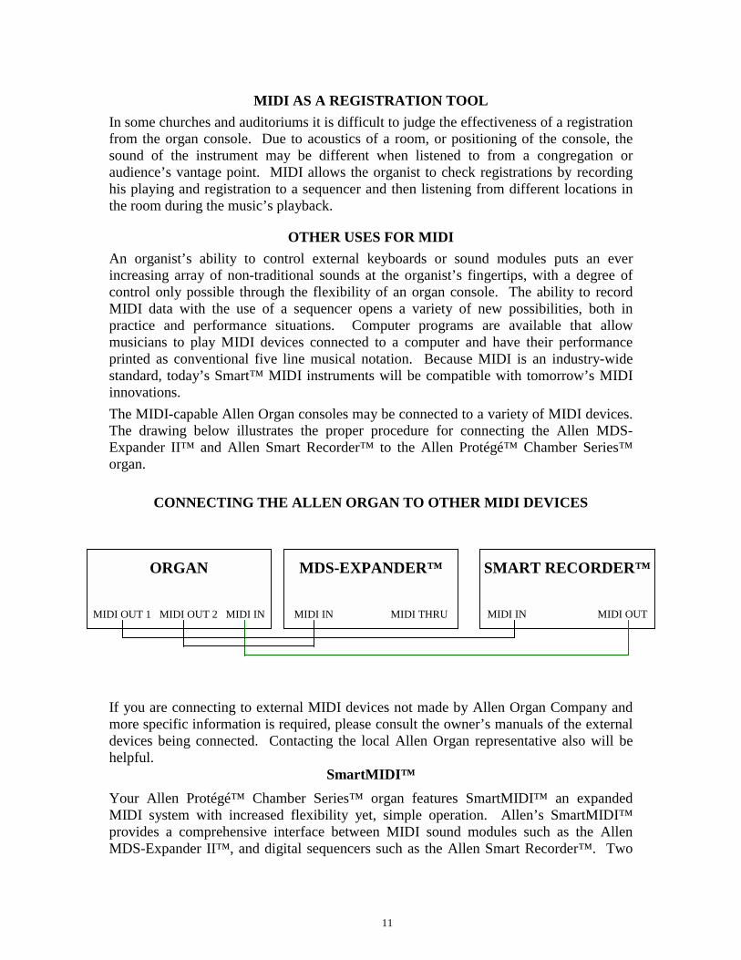
OTHER USES FOR MIDIAn organist’s ability to control external keyboards or sound modules puts an everincreasing array of non-traditional sounds at the organist’s fingertips, with a degree ofcontrol only possible through the flexibility of an organ console. The ability to recordMIDI data with the use of a sequencer opens a variety of new possibilities, both inpractice and performance situations. Computer programs are available that allowmusicians to play MIDI devices connected to a computer and have their performanceprinted as conventional five line musical notation. Because MIDI is an industry-widestandard, today’s Smart™ MIDI instruments will be compatible with tomorrow’s MIDIinnovations.The MIDI-capable Allen Organ consoles may be connected to a variety of MIDI devices.The drawing below illustrates the proper procedure for connecting the Allen MDS-Expander II™ and Allen Smart Recorder™ to the Allen Protégé™ Chamber Series™organ.
CONNECTING THE ALLEN ORGAN TO OTHER MIDI DEVICES
If you are connecting to external MIDI devices not made by Allen Organ Company andmore specific information is required, please consult the owner’s manuals of the externaldevices being connected. Contacting the local Allen Organ representative also will behelpful.
SmartMIDI™Your Allen Protégé™ Chamber Series™ organ features SmartMIDI™ an expandedMIDI system with increased flexibility yet, simple operation. Allen’s SmartMIDI™provides a comprehensive interface between MIDI sound modules such as the AllenMDS-Expander II™, and digital sequencers such as the Allen Smart Recorder™. Two
ORGAN
MIDI OUT 1 MIDI OUT 2 MIDI IN
MDS-EXPANDER™
MIDI IN MIDI THRU
SMART RECORDER™
MIDI IN MIDI OUT
12
MIDI Out ports, one switched and one un-switched, allow unprecedented control overexternal MIDI devices attached to the organ.
Under normal circumstances, MIDI sound modules should be connected to the switchedMIDI port labeled MIDI OUT 2. Doing so allows the organist to disable the sending ofMIDI data from the organ to the sound module. Devices such as MIDI sequencers shouldbe connected to the un-switched MIDI port labeled MIDI OUT 1, eliminating thenecessity of having to draw the MIDI stop controls before recording a digital sequence.
MIDI TRANSMISSION CHANNELSMIDI information may be broadcast on several different channels simultaneously. Thisallows many channels of information to be sent through one cable and usedindependently of one another similar to the way several television broadcasts can be sentthrough one cable. In order to receive the intended information, a MIDI device must betuned to the same channel as the devise that is sending the information. Your Allenorgan transmits MIDI information on several channels.
When external MIDI devices are connected to the organ, it is important to make sure thatthe devices' channels of transmission and reception match the MIDI channels of the Allenorgan divisions to which they are assigned.
For example, the C-19c and Protégé Theatre Compact transmit MIDI information on thefollowing channels:
Solo Manual = Channel 1Accomp Manual = Channel 2Pedal Manual = Channel 3General Pistons = Channel 8
MIDI Program Change Messages are transmitted from the organ’s General Pistons onMIDI Channel 8. These program change messages can be used to change the setting ofMIDI sound modules or synthesizers that are connected to the organ. Please consult theowner’s manual of your MIDI device(s) for more information on how MIDI ProgramChange Messages are handled by that particular device.
In addition to note information, MIDI Volume Change Information is sent on MIDIchannels 1, 2, and 3 by the organ’s single expression pedal. In this manner, the volumelevel of connected sound producing MIDI devices may be controlled. Please consultyour MIDI device's owner’s manual for information on how MIDI volume information ishandled by them.
If any external MIDI device is used to transmit information to the organ, the sameassignment of MIDI channels must be used as outlined above.

13
MIDI SETTINGS FOR ALLEN’S MDS-EXPANDER II™
Your Allen Organ comes pre-programmed with organ registration and MIDI presetselection information for an Allen MDS Expander II™ sound module. The pre-programmed settings allow organists to access various presets from pistons of each of theorgan’s capture memory levels when connected to one of these. Note: This informationis not permanent in the memory of the organ, so please make a copy of the currentcapture in the organ if you wish to save those registrations. To review the copyprocess, see the information in the publication “Console Controller Guide for theChamber Series™".
GENERAL PISTON PRE-PROGRAMMED MIDI SETTINGS - PTCMemory 1
Pistons 1 through 7 access Preset 1 through 7 of the MDS-Expander II™.
Memory 2Pistons 1 through 7 access Preset 8 through 14 of the MDS-Expander II™.
Memory 3Pistons 1 through 5 access Preset 15 through 21 of the MDS-Expander II™.
Memory 4Pistons 1 through 5 access Preset 22 through 28 of the MDS-Expander II™.
The following example demonstrates how to program General Piston 5 on Memory 3with a corresponding set of preset Voices from the MDS-Expander II™:
1. First, access Memory Level 3 in the Console Controller.2. Next, program the MDS-Expander II™. Consult the Owner’s Manual for the
MDS-Expander II™ for detailed information on this process.3. Once you have selected the combination you want, press the Set button on the
Expander II™. The window now displays Please Set Capture… .4. Press General Piston 5 on the Organ. The MDS-Expander™ now displays Preset
19 with the voices you have chosen.
GENERAL PISTON PRE-PROGRAMMED MIDI SETTINGS - C-19cMemory 1
Pistons 1 through 5 access Preset 1 through 5 of the MDS-Expander II™.Memory 2
Pistons 1 through 5 access Preset 6 through 10 of the MDS-Expander II™.Memory 3
Pistons 1 through 5 access Preset 11 through 15 of the MDS-Expander II™.Memory 4
Pistons 1 through 5 access Preset 16 through 20 of the MDS-Expander II™.
14
DIVISIONAL PISTONS PRE-PROGRAMMED MIDI SETTINGS - C-19cDivisional Pistons are programmed for the four memories of the organ. Here is how itworks:There are four divisional pistons for the Swell, and four for the Great/Pedal divisions.You can choose one MIDI voice per piston and set them to Pistons 1 through 4.This example programs the Oboe with Trem on Swell piston 3 of Memory 4:
1. Access Memory 4 in the Console Controller
2. Next, on the MIDI MDS-Expander II™, press the Division button until the arrowis blinking at Swell (SW).
3. Next, press the Voice button, then use the Up/Down buttons to scroll to the Oboe.Once the word “Oboe” appears in the window press the Trem button and anasterisk (*) appears.
4. Next, press the Set button which is directly below the Trem button… the windownow displays “Please set capture…”. Press Swell Divisional 3 piston and you havenow locked the Oboe with Trem onto this piston.Note: The organ must be in “User” Mode for all of this to work properly. Check
the first window of the Console Controller to see if there is a “U” in the bottom rightcorner. If not, scroll to Window 2 and set it to User. In Window 6 the Controller must beset to "Low Bank".
Additional information about MIDI is included in the Console Controller Guide thatfollows in this manual.

15
XI. Chamber SeriesConsole Controller™ Guide
A. BASIC OPERATION .........................................................................................161. Start-Up Sequence2. Advancing Through All Windows3. Selecting the 4 Capture Memories4. Saving Registrations Using Pistons5. Locking Capture Memories6. Unlocking Memories Using Your Code7. Unlocking Memories-Even If No One Remembers the Code8. Stop Action and Capture Self Check9. Virtual Acoustics Settings
B. ADVANCED OPERATION ..............................................................................191. Selecting an Alternate Tuning2. Configuring Pistons3. Restoring Original Factory Settings
C. MIDI FUNCTIONS ............................................................................................221. Standard MIDI Channel Assignment2. Selecting Program Change Modes3. GENERAL MIDI Sound Names or Program Numbers4. Assigning MIDI Program Changes to the Organ’s Pistons5. MIDI Bank Selecting6. Changing the MIDI Base Channel7. MIDI Expression Settings8. MIDI Sustain Kick Switch (optional)9. Transferring and Saving Capture Data to a Sequencer
10. Return Capture Memory Data From a Sequencer11. Transmitting Stop Data
D. QUICK REFERENCE GUIDE.........................................................................29

16
IntroductionThe Console Controller™ is an interface that controls many organ functions and a varietyof MIDI functions. It includes a window that displays functions one at a time, twofunction buttons and a rotary dial that may be used to make selections. Each windowfunction is described here in detail.
A. BASIC OPERATION1. START-UP SEQUENCEUpon turning on the organ's main power switch the Console Controller™ will display"Allen Organ Co. Copyright (©) 2000" in its display window for several seconds.During this start-up period do not press any keys, pedals, stops or move the expressionshoe(s). You may also notice that the power LED will blink momentarily as well as thestop indicators. The organ's computer is booting up during this time period and this isconsidered a NORMAL condition. The organ will be ready to play when the Mainwindow function appears on the Console Controller™ and the power LED glowssteadily.
The Main window function is the window that indicates the current capture memory aswell as the current Transposer value. The capture memory value is on the first line at theupper left of the display. The Transposer value is located on the right side of the display.The Transposer value actually encompasses both lines.
WARNING: If a warning is displayed in the start-up sequence, contact your authorizedAllen representative immediately.
2. ADVANCING THROUGH ALL WINDOWSTo advance the Console Controller™ display to each next window, press the CURSORbutton until the blinking CURSOR is over the abbreviation MEM in the display. Oncethe abbreviation MEM is highlighted, slowly turn the ROTARY DIAL clockwise andthe display will advance to the next window function. When the second window functionis displayed, rotate the ROTARY DIAL counter-clockwise, the window will return tothe Main window display function. Turn the ROTARY DIAL counter-clockwise againand the last window function will display.
REMEMBER: You may return to the Main Window function at any time by pressingand holding the SET piston. Then, while holding SET, press the CANCEL piston, thenrelease both pistons. This process will always return the Console Controller’s display tothe Main Window function.
3. SELECTING THE FOUR CAPTURE MEMORIESThe Main window function must be displayed (See Section A-2). Locate the “CURSOR”button on the face of the Console Controller™. Press this button to move the cursor tothe first number to the right of the abbreviation “MEM”. Once the memory number isselected, turn the ROTARY DIAL clockwise to select the memories sequentially fromMEM 1, to MEM 2, to MEM 3. Or, turn the ROTARY DIAL Counter-Clockwise toselect the memories sequentially from MEM 1, to MEM 4, to MEM 3.

17
The 4 memories allow you to save different registrations on each piston/toe piston 4times. This means General Piston 1 on MEM-1, may be totally different from GeneralPiston 1 on MEM-2, MEM-3, or MEM-4.NOTE: On standard models a factory pre-registered set of registration examples is storedon each piston of the last capture memory (Memory 4). You may change Memory 4registrations to your preferred registrations knowing they can be restored to these originalfactory settings. Please see, RESTORING FACTORY SETTINGS referenced later inthis manual.
4. SAVING REGISTRATIONS USING PISTONSA registration is any combination of stops. These registrations can be stored(remembered) by the organ’s capture memory system. The pistons and toe studs/toepistons provide a way to make changes quickly from one registration to another.
General Pistons are those that affect all stops on the organ. Divisional Pistons affectonly those stops associated with the particular manual above them.
To save a registration to a General Piston.The Main window function in the Console Controller™ must be displayed (See SectionA-2). Select any memory number (MEM-2, MEM-3, or MEM-4, etc.); however, for thisexample use MEM-1.
Next, select the stops you want General Piston 1 to remember. Once the stops areilluminated, press and hold the SET piston and while holding it, press and releaseGeneral Piston 1.Finally, release the SET piston. General Piston 1 will now store in Memory 1 the stopsyou selected.
NOTE: General Pistons are sometimes set gradually from soft to loud. General 1 issoftest and General 5 or 7 the loudest.
Save Registrations to a Divisional Piston. (Applicable for some models)The Main window function in the Console Controller™ must be displayed, (See SectionA-2). Select a memory (MEM-1, MEM-2, etc.) as aforementioned for the GeneralPistons. Select the division stops you want the associated Divisional piston toremember. While holding the SET piston, press and release a Divisional Piston youwant to save to. Finally, release the SET piston. The Divisional Piston you pressed willnow store the combination of stops you illuminated in the memory you selected.
Registering the Intermanual Couplers.The intermanual coupler’s, (e.g., Swell to Great, Great to Pedal, etc.) settings can beremembered only by the General pistons, not the Divisional pistons, that is unless, theDivisional pistons are reconfigured. (See Section B-2).
5. LOCKING CAPTURE MEMORIESAll memories except Memory 1 may be locked or unlocked individually to preventunintentional or unauthorized changes to that memory’s contents. Memory 1 remainsunlocked as a convenience to visiting or substitute organists. Therefore it is importantnot to place any registrations you do not wish to lose in Memory 1.
18
The Main window function in the Console Controller™ must be displayed, (See SectionA-2). Select the memory (2 to 4) you wish to lock by highlighting the memory numberand turning the ROTARY DIAL to the memory you want to lock.
Once you have stored your registrations to pistons, (See Section A-4) choose three digitsyou can easily remember (e.g., 1-2-3, 1-1-1, etc.). Any combination of three numberswill do. Use General Piston 1 for the number one digit, General Piston 5 for the five digitand General Piston 7 for the seven digit if available. You may only use the GeneralPistons for this function. Divisional Pistons (if applicable) will not work.
With the memory number you wish to lock still selected, locate the button with MEMabove it on the Console Controller™. Press and hold the MEM button. Whileholding the MEM button, press the General Pistons that correspond to your threedigit code one at a time in the order of your selected code. In other words, if yourselected code is 1-5-5, press and hold the MEM button on the Console Controller™, thenpress and release General Piston 1, then press and release General Piston 5, and onceagain press and release General Piston 5. You may now release the MEM button on theConsole Controller™. This procedure will cause an "L" to appear next to the MEMnumber on the display window indicating this memory is now locked. As long as itremains locked, the piston registrations on that memory cannot be changed. Otherorganists will still be able to use these locked registrations however, they will not be ableto change them. Again, it is important to choose a three digit code that will be easy toremember.
6. UNLOCKING MEMORIES USING YOUR CODEThe Main window function on the Console Controller™ must be displayed: (See SectionA-2) To unlock a memory using your three digit code, select the memory to be unlocked.Once selected, press and hold the MEM button on the Console Controller™. Whilepressing the MEM button, enter the same three-digit code that was used to lock thismemory (See Section A-5), using the General Pistons. Remember, Divisional Pistonswill not operate this function, only General Pistons will. Release the MEM button. The"L" will disappear, indicating that this memory is now unlocked.
Should a memory be locked and no one knows the code, it can still be unlocked. (SeeSection A-7)7. UNLOCKING ALL CAPTURE MEMORIES—(Without code)Advance to the window function: "UNLOCK ALL CAPTURE MEMORIES". (SeeSection A-2) Press and hold the MEM button on the Console Controller™, then pressGeneral Pistons 2-5-5 in sequence one at a time. Release the MEM button on theConsole Controller™, the window will display DONE!! when the organ is finishedunlocking all the capture memories. The window display will then automatically returnto the Main window function. All capture memories are now unlocked, including thosememories, other organists may have locked. Registrations in all memories will remainunchanged.
8. STOP ACTION and CAPTURE SELF CHECKThis feature self-checks the capture system. It tests to insure each stop is functioningproperly and able to be controlled by the capture system. Advance to the windowfunction: "SELF CHECK". (See section A-2) To start self-check, move the cursor to
19
highlight OFF then turn the ROTARY DIAL until the display changes to ON. In asecond or two, the self testing process will begin. During this self testing procedure eachstop will illuminate ON then OFF sequentially. If any stop does not illuminate, notifyyour Allen Organ authorized service technician.During this testing process you can interrupt and return to the Main window function atany time. Press and hold the SET piston, then press the CANCEL piston and thenrelease both. The testing process will stop and the window will return to the Mainwindow function.
9. VIRTUAL ACOUSTICS SETTINGSThere are 21 Virtual Acoustic reverb pallets to select from. One of these is theDEFAULT setting that is not adjustable. The other 20 styles are adjustable. This allowsan organist to modify the sound of the organ to accommodate a room’s changingacoustical properties. (E.g., a room’s natural reverberation characteristics become lessreverberant as the number of people present increases. A room’s reverberation timechanges when a room’s windows are opened or closed. It also changes with differentlevels of humidity.)
The rocker switch labeled VIRTUAL ACOUSTICS on the Console Controller™ must beON to hear the default reverb or one of the 20 customized Virtual Acoustic selections.The Virtual Acoustics switch on the Console Controller™ has graphics that are depictedas a LINE and a CIRCLE. The LINE on the switch is ON and the CIRCLE on the switchis OFF. The amount of reverberation can be changed on the 20 customized selections.The amount of reverb is shown in dB (decibels). The range of control is from Ø dB to -3Ø dB. -3Ø dB is the least amount of reverb and Ø dB is the most reverb available.
To access the Virtual Acoustic settings, advance to the Set Reverb window function (SeeSection A-2). The window will display: "SET REVERB" and list one of 20 reverb typeson the window's second line. For example, to change to a different reverb type press theCURSOR button on the Console Controller™ until the cursor is on the second line of thedisplay and on the reverb type. Once the cursor is positioned, turn the ROTARY DIALto select another reverb type. The display will also show the current amount ofreverberation applied to the setting selected. To change the amount of reverberationapplied to the selected reverb type, press the CURSOR button until the cursor is on thereverb amount (the decibel number). Turn the ROTARY DIAL to change the amount ofreverberation. The amount of reverb is shown in dB (decibels). The range of control isfrom Ø dB to -3Ø dB. -3Ø dB is the least amount of reverb and Ø dB is the most reverbavailable.
B. ADVANCED OPERATION1. SELECTING AN ALTERNATE TUNINGAdvance to the Alternate Tuning window function (See Section A-2). It will display:"ALTERNATE TUNING". (The current Alternate Tuning will appear after =.)AllenChamber Series Organs offer seven Alternate Tuning Temperaments, plus the standardRomantic tuning. These seven are accessible from the Console Controller™.
To select an Alternate Tuning from the list, press the CURSOR button on the ConsoleController™ so that the cursor is on the name of the tuning. Turn the ROTARY DIAL to
20
select one of the seven tuning temperaments. The organ’s overall tuning will be changedto the selected Alternate Tuning, once you turn on the stop labeled ALTERNATETUNING.
The selected tuning will remain the Alternate Tuning until either another AlternateTuning shown in the Console Controller™ window is selected, or the ALTERNATETUNING stop is turned OFF. Any time the ALTERNATE TUNING stop is OFF, theorgan is tuned to the standard general purpose Romantic tuning. The standard Romantictuning is “warmer” than the CLASSIC and BAROQUE Alternate Tuning Temperaments.These two alternate tunings are “tighter” than the Romantic tuning. In other words, mostintervals are tuned slightly narrower than the intervals in the standard Romantic tuning.
NOTE: The remaining tunings are primarily of historical interest; however, thesetunings may be limited in their application to modern music. When one of these tuningshas been selected, it is normal for some intervals to sound out of tune; music may soundstrange when played in certain keys.
2. CONFIGURING PISTONSThis procedure enables pistons to control stops that are normally not controlled by thosepistons. Separate piston configuration changes can be made on each capture memory.E.g., A General Piston can be configured to respond like a Divisional Piston.
NOTE I: Changing the configuration of a piston will not affect the registrationspreviously remembered by that piston, prior to its reconfiguration. Piston configurationsapply to all memories.
NOTE II: Reconfiguring a piston does not change its MIDI channel assignment.Divisional Pistons cannot make Expander II™ preset group selections.
TO RECONFIGURE PISTONS:Advance to the Configure Pistons window function (See Section A-2). It will display:"CONFIGURE PISTONS". Press the CURSOR button until the cursor is on the “D”of disabled. Turn the ROTARY DIAL to change the display to ENABLED instead ofDISABLED.
Once ENABLED is displayed, select all of the stops you want the General Pistons to beable to remember. Any stops not illuminated, will not be able to be registered later.
Once the stops you want are selected press and hold the “SET” piston, then press theGeneral Piston that you want to reconfigure. You must return to the Main windowfunction to store registrations to this General piston. (See Section A-4)
EXAMPLESCONFIGURING A GENERAL PISTON TO BECOME A DIVISIONAL PISTON:Advance to the Configure Pistons window function (See Section A-2). It will display:"CONFIGURE PISTONS". Press the CURSOR button until the cursor is on the “D”of disabled. Turn the ROTARY DIAL to change the display to ENABLED instead ofDISABLED.
Select all of the stops from only one division. Any stops not illuminated, will not be ableto be registered later. Press and hold the "SET" piston, press the General Piston youwant to respond like a Divisional piston. This piston will only register stops from the

21
selected division. You must return to the Main window function to store Divisionalregistrations to this General piston (See Section A-4).CONFIGURING DIVISIONAL PISTONS (Applicable for some models)Several examples of how this feature might be used are: (1) Divisional Pistons can beconfigured to respond like General Pistons. (2) Divisional Pistons normally will notremember the settings of the Intermanual Couplers, (i. e., Swell to Great, Great to Pedal).Divisional Pistons can be configured such that, the Intermanual Couplers’ settings will beremembered by the Divisional Pistons. (3) A Divisional Piston can be configured so thatit will only affect the Tremulant stops in all divisions.
MAKE DIVISIONAL PISTONS BECOME GENERAL PISTONS:Advance to the Configure Pistons window function (See Section A-2). It will display:"CONFIGURE PISTONS". Press the CURSOR button until the cursor is on the “D”of disabled. Turn the ROTARY DIAL to change the display to ENABLED instead ofDISABLED.
Select all of the stops on the organ. Any stops not illuminated, will not be able to beregistered later. Press and hold the "SET" piston, then press the Divisional piston youwant to make respond like a General piston. This Divisional piston will now registerstops from all divisions. You must return to the Main window function to storeregistrations to this General piston (See Section A-4).
TO ADD "SWELL TO GREAT" INTERMANUAL COUPLER TO GREATDIVISIONAL PISTONS:Advance to the Configure Pistons window function (See Section A-2). It will display:"CONFIGURE PISTONS". Press the CURSOR button until the cursor is on the “D”of disabled. Turn the ROTARY DIAL to change the display to ENABLED instead ofDISABLED.
Select all of the Great Division stops, and the SWELL TO GREAT intermanual coupler.Press and hold the "SET" piston, then press the Divisional Piston(s) that you want theSWELL TO GREAT intermanual coupler assigned to. The Divisional piston(s) youselected will now also register the SWELL TO GREAT intermanual coupler in yourregistrations. You must return to the Main window function (See Section A-4) to saveregistrations to the Divisional Pistons, using combinations of stops and the SWELL TOGREAT coupler.
RECONFIGURE A DIVISIONAL PISTON TO CONTROL ONLY TREMULANTSTOPS:Advance to the Configure Pistons window function (See Section A-2). It will display:"CONFIGURE PISTONS". Press the CURSOR button until the cursor is on the “D”of disabled. Turn the ROTARY DIAL to change the display to ENABLED instead ofDISABLED.
Select all of the organ’s Tremulant Stops. Press and hold the "SET" piston, then press aDivisional piston. The Divisional piston you have selected will now only control theTremulant stops. You must return to the Main window function (See Section A-4) to saveregistrations on this Divisional piston to only control the Tremulant stops.
22
REMEMBER: The above examples determine only which stops will become accessibleby the reconfigured pistons; they will not change previously saved registrations.
3. RESTORING ORIGINAL FACTORY SETTINGSAdvance to the Re-Initialize window function (See Section A-2). It will display: "RE-INITIALIZE PISTON CONFIG." Certain functions can be restored to original factorysettings. These functions are (1) Piston Configurations, (2) Capture Memory 4, (3) MIDISettings. Each of these functions can be restored individually. To select one of thesefactory settings to restore press the CURSOR button on the Console Controller™ untilthe first letter of the bottom line is selected. Turn the ROTARY DIAL to select the itemyou want to re-initialize. Once selected, press and hold the "MEM" button on theConsole Controller™, then press General Pistons 2-5-5 in sequence.
If the Piston Configure function was selected then the original factory pistonconfiguration settings have been restored. Follow this same procedure to restore eachfactory setting.
C. MIDI FUNCTIONSThis section deals with the MIDI capabilities of your organ. Knowledge of this sectionis not required for everyday use of the organ, normal service playing, or normal use ofAllen SmartMIDI™ devices. This information’s usefulness, will ultimately bedetermined by your needs, along with the type and capabilities of any external MIDIdevices you choose to use--e.g., sequencers, voice/sound modules, and external MIDIkeyboards. The MIDI topics covered by this manual are limited in scope, because thissection is written with the assumption that you possess an understanding of MIDI. Youneed to understand the terms MIDI-IN, OUT, and THRU and their function. If you needto increase your understanding of MIDI, there are other books that describe how to useMIDI.
NOTE: You must also consult the owner’s manual that covers the external MIDI deviceyou are using for more details.
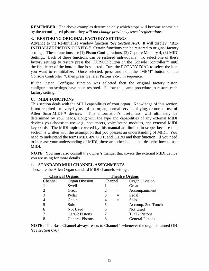
1. STANDARD MIDI CHANNEL ASSIGNMENTSThese are the Allen Organ standard MIDI channels settings:
Classical Organs Theatre OrgansChannel Organ Division Channel Organ Division1 Swell 1 = Great2 Great 2 = Accompaniment3 Pedal 3 = Pedal4 Choir 4 = Solo5 Solo 5 Accomp. 2nd Touch6 Not Used 6 Not Used7 G1/G2 Pistons 7 T1/T2 Pistons8 General Pistons 8 General Pistons
NOTE: The Base Channel always resets to Channel 1 whenever the organ is turned ON(see section C-6).
23
2. SELECTING PROGRAM CHANGE MODES, VIEWING PROGRAMNUMBERS or GENERAL MIDI SOUND NAMESProgram change modes establish how MIDI program changes will be sent from theorgan to receiving MIDI devices when a piston is pressed. Once a particular programchange mode is selected, the organ will retain this same program change mode (even ifthe organ is turned off) until a new program change mode is selected.
One of three Program Change Modes can be selected in the Console Controller™display window. These three modes are named “PRESET”, “USER”, AND “NO”.These three mode options determine how the organ is going to send program changeinformation to MIDI devices. They allow external MIDI device voice changes to occurquickly by simply pressing a piston. This means a MIDI voice can be registered liketraditional organ stops.
SELECTING A PROGRAM CHANGE MODE:Advance to the Program Change window function (See Section A-2). It will display:"PROG CHG" along with other information. Use the CURSOR button on the ConsoleController™ to place the cursor on either USER, PRESET, or NO, whichever one isdisplayed. Once the cursor is positioned, turn the ROTARY DIAL to make a selection.
CAUTION: You must understand how to operate and when to use each of these modesbefore you change them!
PRESET MODE: This mode causes the organ to send a program change number equalto the piston number that is pressed. The General Pistons will send program changes 1through 5 or 7 (depending on your model) on MIDI Channel 8, the organ’s GeneralPiston control channel. The Divisional Pistons (check if applicable on your particularmodel) for each division will send program changes 1 through 4 on the channels asshown in the MIDI channel assignment list (See Section C-1). For example, Swell Piston1 would send Program Change 1 on Channel 1. Great Piston 2 will send ProgramChange 2 on Channel 2, etc., (See Section C-6, Changing the MIDI Base Channel foradditional information on MIDI channel assignments).
USER MODE: With this mode selected the organ will send program changeinformation that can select voices, change banks, or change program “patch” numbers onanother MIDI device. Any program change number from 1 through 128 can be assignedto any General or Divisional Piston (blank or no digits may also be selected). Any bankswitch number between 0 and 127 can be assigned to any Divisional Piston (check ifapplicable on your particular model). As in the PRESET mode, General Pistons willsend program change information on MIDI Channel 8. Divisional Pistons will sendinformation on their respective MIDI channels (See Section C-1).NO MODE: With this mode selected, NO information is transmitted or received. Thismode cancels transmission and reception of all program change information.
3. GENERAL MIDI SOUND NAMES or PROGRAM NUMBERS:The Console Controller™ window can display MIDI program changes as either MIDIprogram numbers or as General MIDI sound names. Use the CURSOR button alongwith the ROTARY DIAL to select one of the two modes.

24
GENERAL MIDI SOUND NAMES:First, make certain the word USER is selected as the program change mode. Then byusing the "CURSOR" button on the Console Controller™, place the cursor on the secondline of the display following the word DISPLAY. Turn the ROTARY DIAL until thedisplay shows GEN MIDI following the word DISPLAY. Advance to the nextwindow function by placing the cursor back on the first line and word "PROG CHG".Then turn the ROTARY DIAL clockwise until the window function "MIDI PROGCHANGE" appears on the display. Press any piston to view the General MIDI soundname assigned to that piston for any General MIDI device.
For example, press General Piston 1. The Console Controller™ will display the MIDIprogram change names.
NOTE: In some cases, the General MIDI sound name will be abbreviated in theConsole Controller™ window.
MIDI PROGRAM NUMBERS:First, make certain the word PRESET is selected as the program change mode. Then byusing the "CURSOR" button on the Console Controller™, place the cursor on the secondline of the display following the word DISPLAY. Turn the ROTARY DIAL until thedisplay shows NUMBERS following the word DISPLAY. Advance to the nextwindow function by placing the cursor back on the first line and word "PROG CHG".Then turn the ROTARY DIAL clockwise until the window function "MIDI PROGCHANGE" appears on the display. Press a General or Divisional Piston. The ConsoleController™ window will display the same MIDI program change number as theassociated piston pressed. A MIDI program change number will be displayed inPRESET mode, no matter if NUMBERS or GEN MIDI is displayed. You must selectUSER mode to view GEN MIDI sound names. You must also select USER mode toassign MIDI program change numbers larger than the overall number of pistons on youmodel organ.
ASSIGNING MIDI PROGRAM CHANGE NUMBERSWith USER selected as the program change mode (See above instructions to changemodes), along with NUMBERS following the word DISPLAY, you will be able toassign “- - -” (OFF) or any program change number from 1 through 128 to any Generalor Divisional Piston.
After selecting NUMBERS along with USER mode, advance to the next windowfunction "MIDI PROG CHANGE", then press a General or Divisional Piston to viewthe Program Change Numbers assigned to that particular piston. After pressing a Generalor Divisional Piston, the Console Controller window will now display the number thathas been selected for that piston. For example, press General Piston 1. The display willchange to indicate that General Piston 1 has been pressed and that BANK 0 is assigned tothat piston. On the second line of the display there may be a number or “- - -” followingthe “P:”. This “P:” represents the Program Change Number and does not stand forPRESET in this window. If there is “- - -” following “P:”, this means that the “ZERO”Program Change Number will be sent from the associated piston.
25
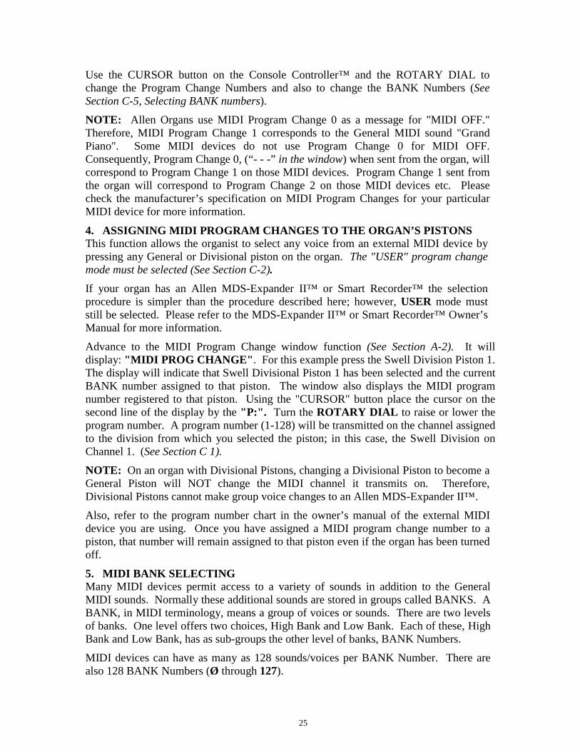
Use the CURSOR button on the Console Controller™ and the ROTARY DIAL tochange the Program Change Numbers and also to change the BANK Numbers (SeeSection C-5, Selecting BANK numbers).
NOTE: Allen Organs use MIDI Program Change 0 as a message for "MIDI OFF."Therefore, MIDI Program Change 1 corresponds to the General MIDI sound "GrandPiano". Some MIDI devices do not use Program Change 0 for MIDI OFF.Consequently, Program Change 0, (“- - -” in the window) when sent from the organ, willcorrespond to Program Change 1 on those MIDI devices. Program Change 1 sent fromthe organ will correspond to Program Change 2 on those MIDI devices etc. Pleasecheck the manufacturer’s specification on MIDI Program Changes for your particularMIDI device for more information.
4. ASSIGNING MIDI PROGRAM CHANGES TO THE ORGAN’S PISTONSThis function allows the organist to select any voice from an external MIDI device bypressing any General or Divisional piston on the organ. The "USER" program changemode must be selected (See Section C-2).If your organ has an Allen MDS-Expander II™ or Smart Recorder™ the selectionprocedure is simpler than the procedure described here; however, USER mode muststill be selected. Please refer to the MDS-Expander II™ or Smart Recorder™ Owner’sManual for more information.
Advance to the MIDI Program Change window function (See Section A-2). It willdisplay: "MIDI PROG CHANGE". For this example press the Swell Division Piston 1.The display will indicate that Swell Divisional Piston 1 has been selected and the currentBANK number assigned to that piston. The window also displays the MIDI programnumber registered to that piston. Using the "CURSOR" button place the cursor on thesecond line of the display by the "P:". Turn the ROTARY DIAL to raise or lower theprogram number. A program number (1-128) will be transmitted on the channel assignedto the division from which you selected the piston; in this case, the Swell Division onChannel 1. (See Section C 1).NOTE: On an organ with Divisional Pistons, changing a Divisional Piston to become aGeneral Piston will NOT change the MIDI channel it transmits on. Therefore,Divisional Pistons cannot make group voice changes to an Allen MDS-Expander II™.
Also, refer to the program number chart in the owner’s manual of the external MIDIdevice you are using. Once you have assigned a MIDI program change number to apiston, that number will remain assigned to that piston even if the organ has been turnedoff.
5. MIDI BANK SELECTINGMany MIDI devices permit access to a variety of sounds in addition to the GeneralMIDI sounds. Normally these additional sounds are stored in groups called BANKS. ABANK, in MIDI terminology, means a group of voices or sounds. There are two levelsof banks. One level offers two choices, High Bank and Low Bank. Each of these, HighBank and Low Bank, has as sub-groups the other level of banks, BANK Numbers.
MIDI devices can have as many as 128 sounds/voices per BANK Number. There arealso 128 BANK Numbers (Ø through 127).
26
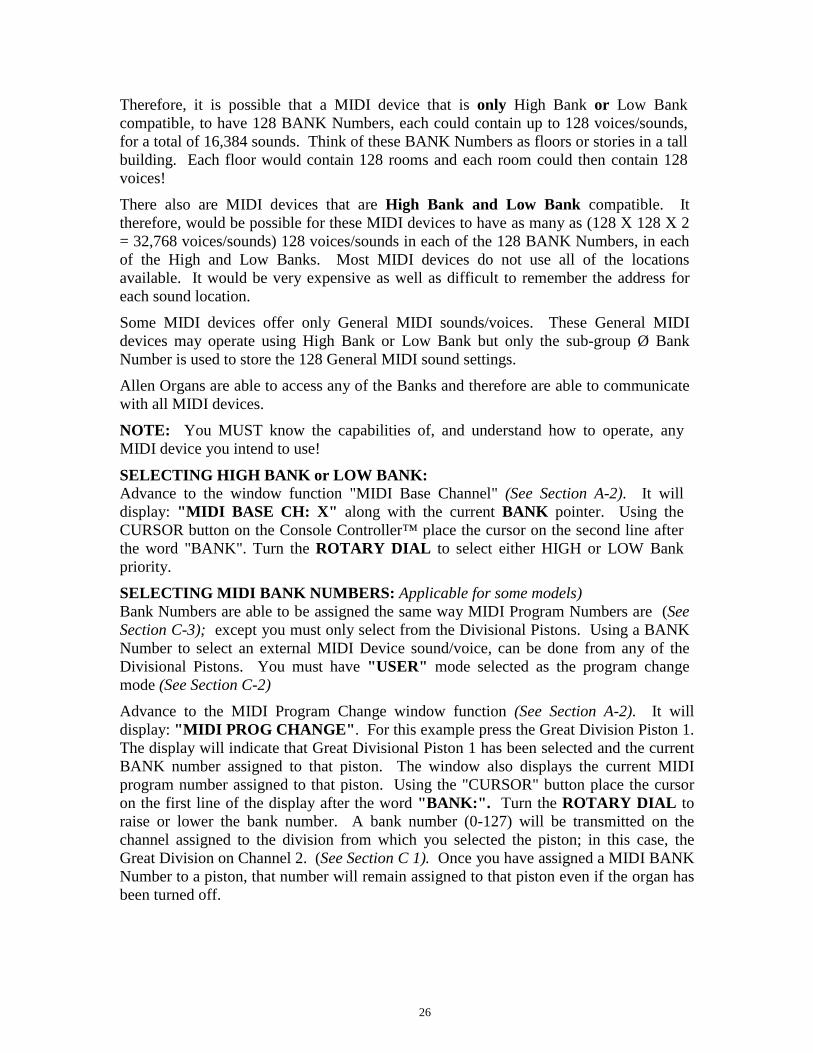
Therefore, it is possible that a MIDI device that is only High Bank or Low Bankcompatible, to have 128 BANK Numbers, each could contain up to 128 voices/sounds,for a total of 16,384 sounds. Think of these BANK Numbers as floors or stories in a tallbuilding. Each floor would contain 128 rooms and each room could then contain 128voices!
There also are MIDI devices that are High Bank and Low Bank compatible. Ittherefore, would be possible for these MIDI devices to have as many as (128 X 128 X 2= 32,768 voices/sounds) 128 voices/sounds in each of the 128 BANK Numbers, in eachof the High and Low Banks. Most MIDI devices do not use all of the locationsavailable. It would be very expensive as well as difficult to remember the address foreach sound location.
Some MIDI devices offer only General MIDI sounds/voices. These General MIDIdevices may operate using High Bank or Low Bank but only the sub-group Ø BankNumber is used to store the 128 General MIDI sound settings.
Allen Organs are able to access any of the Banks and therefore are able to communicatewith all MIDI devices.
NOTE: You MUST know the capabilities of, and understand how to operate, anyMIDI device you intend to use!
SELECTING HIGH BANK or LOW BANK:Advance to the window function "MIDI Base Channel" (See Section A-2). It willdisplay: "MIDI BASE CH: X" along with the current BANK pointer. Using theCURSOR button on the Console Controller™ place the cursor on the second line afterthe word "BANK". Turn the ROTARY DIAL to select either HIGH or LOW Bankpriority.
SELECTING MIDI BANK NUMBERS: Applicable for some models)Bank Numbers are able to be assigned the same way MIDI Program Numbers are (SeeSection C-3); except you must only select from the Divisional Pistons. Using a BANKNumber to select an external MIDI Device sound/voice, can be done from any of theDivisional Pistons. You must have "USER" mode selected as the program changemode (See Section C-2)Advance to the MIDI Program Change window function (See Section A-2). It willdisplay: "MIDI PROG CHANGE". For this example press the Great Division Piston 1.The display will indicate that Great Divisional Piston 1 has been selected and the currentBANK number assigned to that piston. The window also displays the current MIDIprogram number assigned to that piston. Using the "CURSOR" button place the cursoron the first line of the display after the word "BANK:". Turn the ROTARY DIAL toraise or lower the bank number. A bank number (0-127) will be transmitted on thechannel assigned to the division from which you selected the piston; in this case, theGreat Division on Channel 2. (See Section C 1). Once you have assigned a MIDI BANKNumber to a piston, that number will remain assigned to that piston even if the organ hasbeen turned off.
27
6. CHANGING the MIDI BASE CHANNELThis operation allows you to change the setting of the MIDI Base Channel. The BaseChannel is a reference point to establish the positioning of the other 15 MIDI channels inrelationship to it. On Allen Organs, the Base Channel equals the Swell Division’schannel of transmission (i.e., if the Base Channel = 1, then the Swell Channel = 1, if theBase Channel = 2, then the Swell Channel = 2, etc.). Moving the Base Channel shiftsthe organ’s range of MIDI channels. This is helpful when reassigning an external MIDIdevice from one organ division to another. NOTE: The Base Channel always resets toChannel 1 whenever the organ is turned on.
Advance to the MIDI Base Channel window function (See Section A-2). It will display"MIDI BASE CH: X" and also display the current Bank pointer. Using the"CURSOR" button on the Console Controller™, place the cursor on the channel number,which is on the first line of the display. Turn the ROTARY DIAL to change the BaseChannel number. All functions associated with a particular division will transmit andreceive on its assigned channel. For example, MIDI Channel 1 is normally assigned tothe Swell Division and the Swell Manual; therefore, keying on/off messages, andprogram changes (Swell Divisional Pistons) will be transmitted and received on Channel1 (See Section C-1 MIDI Channel Assignments).
If the Base Channel is reset to number 2, in the display, all of the subsequent channelswill shift higher by one number. Now, Swell = 2, Great = 3, Pedal = 4, Choir = 5, andGeneral Pistons = 9.
NOTE: Channel numbers will wrap, i.e. channel numbers go only to 16 and will thenrepeat to 1. FOR NORMAL USE, DO NOT USE A BASE CHANNEL LARGERTHAN 9.
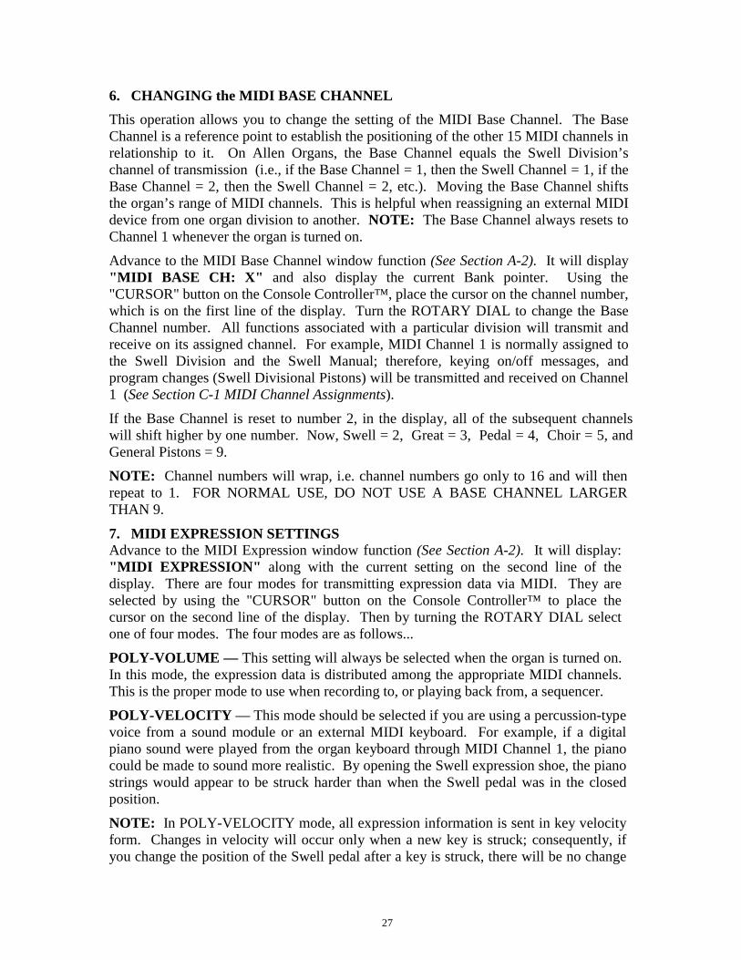
7. MIDI EXPRESSION SETTINGSAdvance to the MIDI Expression window function (See Section A-2). It will display:"MIDI EXPRESSION" along with the current setting on the second line of thedisplay. There are four modes for transmitting expression data via MIDI. They areselected by using the "CURSOR" button on the Console Controller™ to place thecursor on the second line of the display. Then by turning the ROTARY DIAL selectone of four modes. The four modes are as follows...
POLY-VOLUME — This setting will always be selected when the organ is turned on.In this mode, the expression data is distributed among the appropriate MIDI channels.This is the proper mode to use when recording to, or playing back from, a sequencer.
POLY-VELOCITY — This mode should be selected if you are using a percussion-typevoice from a sound module or an external MIDI keyboard. For example, if a digitalpiano sound were played from the organ keyboard through MIDI Channel 1, the pianocould be made to sound more realistic. By opening the Swell expression shoe, the pianostrings would appear to be struck harder than when the Swell pedal was in the closedposition.
NOTE: In POLY-VELOCITY mode, all expression information is sent in key velocityform. Changes in velocity will occur only when a new key is struck; consequently, ifyou change the position of the Swell pedal after a key is struck, there will be no change
28
in velocity until a new key is struck. Use this mode only when a velocity-sensitiveexternal MIDI device is connected. If this mode is selected when recording to asequencer, the expression on the organ will not function when playing back from thesequencer.
SWELL-VOLUME — This mode causes MIDI expression data to be sent only on theSwell MIDI channel. Some early sequencers can only interpret one volume message.NO EXPRESSION — No MIDI expression (volume) data sent.
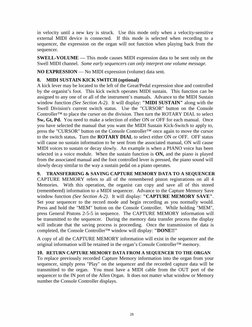
8. MIDI SUSTAIN KICK SWITCH (optional)A kick lever may be located to the left of the Great/Pedal expression shoe and controlledby the organist’s foot. This kick switch operates MIDI sustain. This function can beassigned to any one of or all of the instrument’s manuals. Advance to the MIDI Sustainwindow function (See Section A-2). It will display: "MIDI SUSTAIN" along with theSwell Division's current switch status. Use the "CURSOR" button on the ConsoleController™ to place the cursor on the division. Then turn the ROTARY DIAL to selectSw, Gt, Pd. You need to make a selection of either ON or OFF for each manual. Onceyou have selected the manual that you want the MIDI Sustain Kick-Switch to apply to,press the "CURSOR" button on the Console Controller™ once again to move the cursorto the switch status. Turn the ROTARY DIAL to select either ON or OFF. OFF statuswill cause no sustain information to be sent from the associated manual, ON will causeMIDI voices to sustain or decay slowly. An example is when a PIANO voice has beenselected in a voice module. When the sustain function is ON, and the piano is playedfrom the associated manual and the foot controlled lever is pressed, the piano sound willslowly decay similar to the way a sustain pedal on a piano operates.
9. TRANSFERRING & SAVING CAPTURE MEMORY DATA TO A SEQUENCERCAPTURE MEMORY refers to all of the remembered piston registrations on all 4Memories. With this operation, the organist can copy and save all of this stored(remembered) information to a MIDI sequencer. Advance to the Capture Memory Savewindow function (See Section A-2). It will display: "CAPTURE MEMORY SAVE".Set your sequencer to the record mode and begin recording as you normally would.Press and hold the "MEM" button on the Console Controller. While holding "MEM",press General Pistons 2-5-5 in sequence. The CAPTURE MEMORY information willbe transmitted to the sequencer. During the memory data transfer process the displaywill indicate that the saving process is proceeding. Once the transmission of data iscompleted, the Console Controller™ window will display: "DONE!!"A copy of all the CAPTURE MEMORY information will exist in the sequencer and theoriginal information will be retained in the organ’s Console Controller™ memory.
10. RETURN CAPTURE MEMORY DATA FROM A SEQUENCER TO THE ORGANTo replace previously recorded Capture Memory information into the organ from yoursequencer, simply press "Play" on the sequencer and the recorded capture data will betransmitted to the organ. You must have a MIDI cable from the OUT port of thesequencer to the IN port of the Allen Organ. It does not matter what window or Memorynumber the Console Controller displays.
29
NOTE: Capture Memories must be unlocked (see section A-6) before you press“Play” on the sequencer, allowing the organ’s 4 memories to receive captureinformation. It is a good idea to first save whatever is stored in the organ’s memorybecause, it will be erased by this procedure.
11. TRANSMITTING STOP DATAThis operation allows the organist to turn off the transmission and reception ofindividual stop data, known in MIDI terminology as "Non-Registered Parameters". Insome cases, individual stop data (on/off) from the organ may conflict with data from anexternal MIDI device. To turn OFF or ON the transmission and reception of individualstop data, advance to the Transmit/Receive Stop window function (See Section A-2). Itwill display: "TRANSMIT/RECEIVE STOPS XXX". Using the "CURSOR" buttonon the Console Controller™, place the cursor on the second line after the word"STOPS". This position is this function's status. Turn the ROTARY DIAL to selecteither ON or OFF.
NOTE: General Pistons or Divisional Piston changes will still be transmitted andreceived, because they are program changes.
D. QUICK REFERENCE GUIDEa. ADVANCING THROUGH THE WINDOWS: Press the CURSOR button so as tohighlight the first letter of the first line; then rotate the ROTARY DIAL.
b. TO RETURN TO THE FIRST WINDOW: Press and hold SET, press CANCEL,release both.
c. SETTING PISTONS: First window. Select desired Memory. Select desiredregistration. Press and hold SET and press the piston to remember the registration.Release both.
d. TO SELECT A MEMORY AND LOCK IT: First window. Select desired memoryusing the CURSOR button and ROTARY DIAL. Press and hold MEM, enter three-digit code, release MEM. "L" will appear.
e. TO UNLOCK A MEMORY: Repeat d. above. "L" will disappear.
f. TO UNLOCK ALL MEMORIES WITHOUT A CODE: Locate the display "UnlockAll Capture Memories". Press and hold MEM, press General Pistons 2-5-5, releaseMEM. Window will display "Done!"g. SELF-CHECK CAPTURE AND STOP ACTION: Advance to the display: "Self-Check". Press Great Piston 1. To discontinue, Press and hold SET, press CANCEL,release both, return to the Main window function.