proteus payload user’s guide - scaled.com · the proteus aircraft is a multipurpose manned...
TRANSCRIPT
PROTEUS PAYLOAD USER’S GUIDE The most versatile, capable, and cost efficient airborne research platform available.
SCR 03-014 29 September 2003
Revised
15 December 2015
Scaled Composites, LLC 1624 Flight Line
Mojave, CA 93501-1663 Telephone: (661) 824-4541
Fax: (661) 824-4174 www.scaled.com
PAYLOAD USER’S GUIDE
SCR 03-014 Rev. D Scaled Composites, LLC i
POINTS OF CONTACT
NEW BUSINESS
Erik Hoffman
Scaled Composites 661-824-4541
PROJECT ENGINEERING
Sam Henney
Scaled Composites 661-824-4541

PAYLOAD USER’S GUIDE
SCR 03-014 Rev. D Scaled Composites, LLC i
TABLE OF CONTENTS 1. PROTEUS SUMMARY 1
2. AIRCRAFT DIMENSIONS AND WEIGHTS 1
2.1 BASIC DIMENSIONS 1 2.2 WEIGHTS 1 2.3 3-VIEW 2
3. FLIGHT ENVELOPE 3
3.1 DESIGN LIMITS 3
4. PERFORMANCE 3
4.1 ESTIMATION OF MAXIMUM CRUISE RANGE 3 4.2 LOITER ENDURANCE 5 4.3 AIRCRAFT SERVICE CEILING 5
5. PAYLOAD INTEGRATION OPTIONS 6
5.1 OVERVIEW OF INTEGRATION PROCESS, CHECKOUT, AND DEPLOYMENT 6
6. PROTEUS ON-BOARD SERVICES 7
6.1 VHF X 2/UHF/IRIDIUM SATELLITE PHONE 7 6.2 LOS TELEMETRY OVER L-BAND/S-BAND (LOCAL FLIGHTS ONLY) 7 6.3 INS 7 6.4 GPS NAVIGATION 7 6.5 GPS SPLITTER/ANTENNAS 7 6.6 AUTOPILOT 7 6.7 POWER 7 6.8 COCKPIT INTERFACE 8
7. PAYLOAD ENVIRONMENT 8
8. PAYLOAD INTERFACE 8
8.1 MECHANICAL INTERFACE 8 8.2 GPS SIGNAL 8 8.3 PAYLOAD CONNECTOR 9 8.4 COCKPIT CONNECTOR 9 8.5 ETHERNET (QTY. 2) 9
9. FLIGHT OPERATIONS 10
9.1 FLIGHT SAFETY 10 9.2 CONFIGURATION CONTROL 10 9.3 SCHEDULING 10 9.4 BRIEFINGS 10 9.6 TECHNICAL INTERCHANGE MEETING 11 9.7 FLIGHT READINESS REVIEW 11 9.8 PREFLIGHT 11 9.9 POST FLIGHT 11 9.10 TESTING 12 9.11 GROUND SUPPORT EQUIPMENT FOR DEPLOYMENTS 12 9.12 DEPLOYMENT LOCATION REQUIREMENTS 12
PAYLOAD USER’S GUIDE
SCR 03-014 Rev. D Scaled Composites, LLC ii
10. SELECTION OF PREVIOUS CAMPAIGNS 13
10.1 NASA LANGLEY POD 13 10.2 ANGEL TECHNOLOGIES AND RAYTHEON TELECOMMUNICATIONS DISH 13 10.3 AIRBORNE LASER TARGET BODY 14 10.4 SANDIA NATIONAL LABORATORY 14 10.5 MP-RTIP 15
11. GETTING STARTED WITH YOUR PAYLOAD 15
11.1 INITIAL PAYLOAD INFORMATION REQUIRED 15 11.2 NEXT STEPS 16
12. AVAILABILITY AND CONTRACTS 16
12.1 PLATFORM AVAILABILITY 16 12.2 CONTRACTING 16
TABLE OF TABLES TABLE 1 – PROTEUS BASIC DIMENSIONS 1 TABLE 2 – PROTEUS WEIGHTS 1 TABLE 3 – DESIGN LIMITS 3 TABLE 4 – BASIC PERFORMANCE 3 TABLE 5 – STANDARD PAYLOAD ELECTRICAL INTERFACE 9
TABLE OF FIGURES
FIGURE 1 – PROTEUS 3-VIEW 2 FIGURE 2 – PROTEUS FLIGHT ENVELOPE 4 FIGURE 3 – MAX CRUISE RANGE VS. PAYLOAD WEIGHT FOR 14,500 LB GTOW 4 FIGURE 4 – MAX LOITER ENDURANCE VS. PAYLOAD WEIGHT FOR 14,500 LB GTOW 5 FIGURE 5 – AIRCRAFT SERVICE CEILING 6 FIGURE 6 – NASA LANGLEY POD IN FLIGHT 13 FIGURE 7 – ANGEL TECHNOLOGIES AND RAYTHEON TELECOM DISH IN FLIGHT 13 FIGURE 8 – AIRBORNE LASER TARGET BODY IN FLIGHT 14 FIGURE 9 – SANDIA NATIONAL LABORATORY POD IN FLIGHT 14 FIGURE 10 – MP-RTIP POD IN FLIGHT 15
PAYLOAD USER’S GUIDE
SCR 03-014 Rev. D Scaled Composites, LLC 1
1. PROTEUS SUMMARY The Proteus aircraft is a multipurpose manned platform for long duration high-altitude research. While optimized for high-altitude operations, Proteus is a favorable platform all regimes of airborne research. The aircraft configuration is designed to carry payloads in multiple areas on the aircraft. The all-composite airframe is powered by two FJ44-2E turbofan engines that have been specially modified by Williams International for high altitude operation. The two crewmembers operate in a shirtsleeve environment in the 8 PSID pressurized cabin. The second crewmember adds flexibility to the mission by providing the capability to run various developmental payload systems without the need for ground controls. The airplane flight controls are through a reversible, mechanical, unboosted system. The retractable tricycle landing gear is electro-hydraulically powered, and the nose wheel steering is manually actuated by the crew’s rudder pedals. Onboard electrical power is 28VDC that is provided by two 400 amp starter-generators.
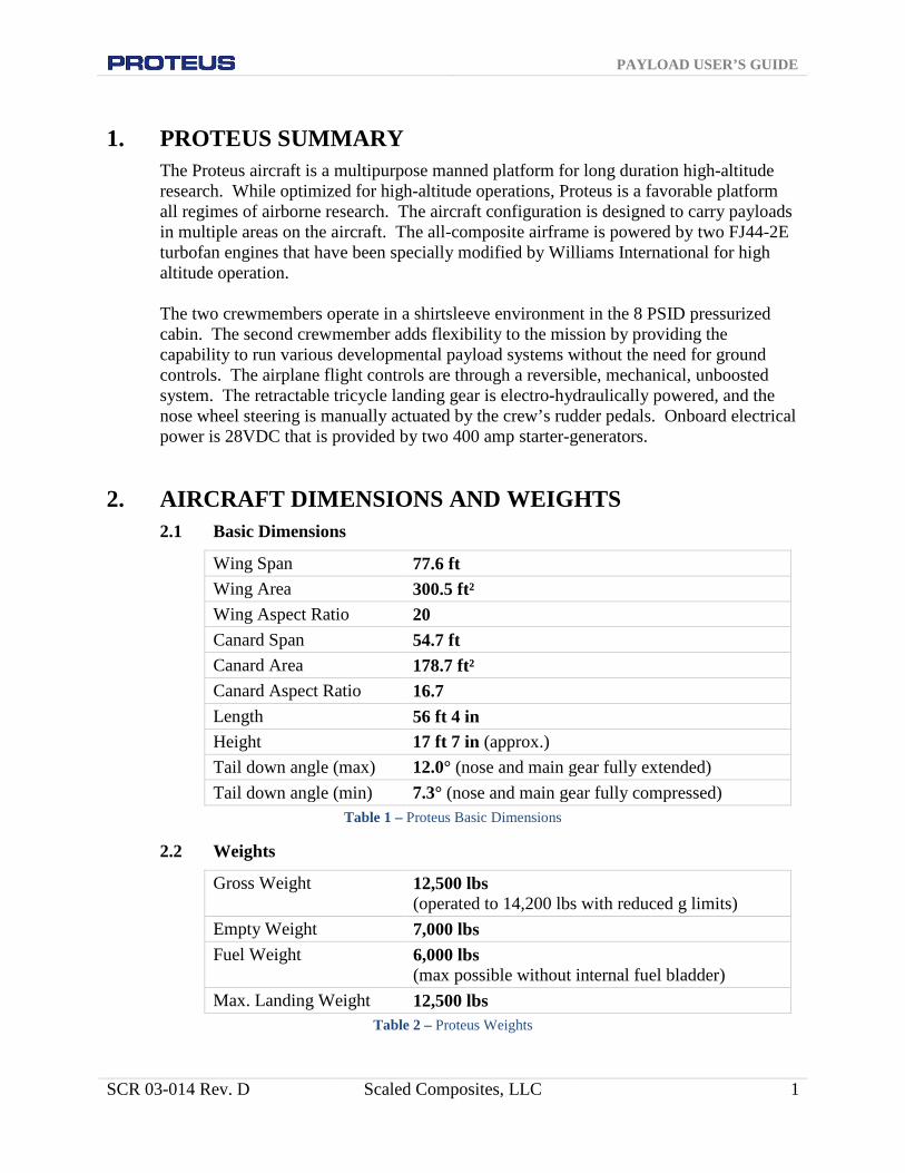
2. AIRCRAFT DIMENSIONS AND WEIGHTS Basic Dimensions 2.1
Wing Span 77.6 ft Wing Area 300.5 ft² Wing Aspect Ratio 20 Canard Span 54.7 ft Canard Area 178.7 ft² Canard Aspect Ratio 16.7 Length 56 ft 4 in Height 17 ft 7 in (approx.) Tail down angle (max) 12.0° (nose and main gear fully extended) Tail down angle (min) 7.3° (nose and main gear fully compressed)
Table 1 – Proteus Basic Dimensions
Weights 2.2
Gross Weight 12,500 lbs (operated to 14,200 lbs with reduced g limits)
Empty Weight 7,000 lbs Fuel Weight 6,000 lbs
(max possible without internal fuel bladder) Max. Landing Weight 12,500 lbs
Table 2 – Proteus Weights

PAYLOAD USER’S GUIDE
SCR 03-014 Rev. D Scaled Composites, LLC 2
3-View 2.3
Figure 1 – Proteus 3-view
PAYLOAD USER’S GUIDE
SCR 03-014 Rev. D Scaled Composites, LLC 3
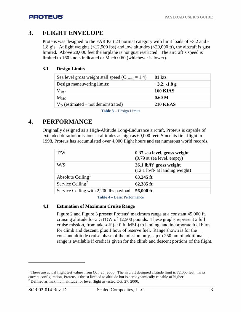
3. FLIGHT ENVELOPE Proteus was designed to the FAR Part 23 normal category with limit loads of +3.2 and -1.8 g’s. At light weights (<12,500 lbs) and low altitudes (<20,000 ft), the aircraft is gust limited. Above 20,000 feet the airplane is not gust restricted. The aircraft’s speed is limited to 160 knots indicated or Mach 0.60 (whichever is lower).
Design Limits 3.1
Sea level gross weight stall speed (CLmax = 1.4) 81 kts Design maneuvering limits: +3.2, -1.8 g VMO 160 KIAS MMO 0.60 M VD (estimated – not demonstrated) 210 KEAS
Table 3 – Design Limits
4. PERFORMANCE Originally designed as a High-Altitude Long-Endurance aircraft, Proteus is capable of extended duration missions at altitudes as high as 60,000 feet. Since its first flight in 1998, Proteus has accumulated over 4,000 flight hours and set numerous world records.
T/W 0.37 sea level, gross weight
(0.79 at sea level, empty) W/S 26.1 lb/ft² gross weight
(12.1 lb/ft² at landing weight) Absolute Ceiling1 63,245 ft Service Ceiling2 62,385 ft Service Ceiling with 2,200 lbs payload 56,000 ft
Table 4 – Basic Performance
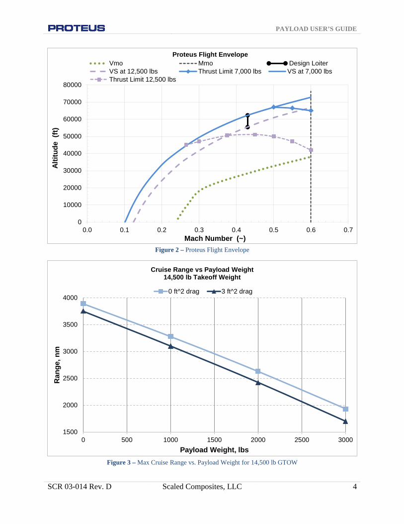
Estimation of Maximum Cruise Range 4.1Figure 2 and Figure 3 present Proteus’ maximum range at a constant 45,000 ft. cruising altitude for a GTOW of 12,500 pounds. These graphs represent a full cruise mission, from take-off (at 0 ft. MSL) to landing, and incorporate fuel burn for climb and descent, plus 1 hour of reserve fuel. Range shown is for the constant altitude cruise phase of the mission only. Up to 250 nm of additional range is available if credit is given for the climb and descent portions of the flight.
1 These are actual flight test values from Oct. 25, 2000. The aircraft designed altitude limit is 72,000 feet. In its current configuration, Proteus is thrust limited to altitude but is aerodynamically capable of higher. 2 Defined as maximum altitude for level flight as tested Oct. 27, 2000.
PAYLOAD USER’S GUIDE
SCR 03-014 Rev. D Scaled Composites, LLC 4
Figure 2 – Proteus Flight Envelope
Figure 3 – Max Cruise Range vs. Payload Weight for 14,500 lb GTOW
0
10000
20000
30000
40000
50000
60000
70000
80000
0.0 0.1 0.2 0.3 0.4 0.5 0.6 0.7
Altit
ude
(ft)
Mach Number (~)
Proteus Flight Envelope Vmo Mmo Design LoiterVS at 12,500 lbs Thrust Limit 7,000 lbs VS at 7,000 lbsThrust Limit 12,500 lbs
1500
2000
2500
3000
3500
4000
0 500 1000 1500 2000 2500 3000
Ran
ge, n
m
Payload Weight, lbs
Cruise Range vs Payload Weight 14,500 lb Takeoff Weight
0 ft^2 drag 3 ft^2 drag

PAYLOAD USER’S GUIDE
SCR 03-014 Rev. D Scaled Composites, LLC 5
Loiter Endurance 4.2Figure 4 represents the loiter endurance capabilities of the Proteus aircraft at an altitude of 45,000 ft. for a GTOW of 14,500 lbs. This graph represents a full loiter mission, from take-off (at 0 ft. MSL) to landing, and incorporates fuel burn for climb and descent, plus 1 hour of reserve fuel. Endurance shown is for the constant altitude loiter phase of the mission only. More than one hour of additional mission time is available if endurance credit is taken for the climb and descent portions of the flight.
Figure 4 – Max Loiter Endurance vs. Payload Weight for 14,500 lb GTOW
Aircraft Service Ceiling 4.3The service ceiling of Proteus is dependent on a number of variables and program objectives. Some of the key factors that play into the service ceiling include: payload drag, payload weight, payload location, and time required at altitude. Often times the flight profile can be tailored to help meet program objectives when it comes to high-altitude flights, however this is generally at the expense of time on station.
0.00
2.00
4.00
6.00
8.00
10.00
12.00
14.00
0 500 1000 1500 2000 2500 3000
Loite
r End
uran
ces,
hrs
Payload Weight, lbs
Loiter Endurance vs Payload Weight 14,500 lb Takeoff Weight
0 ft^2 drag 3 ft^2 drag

PAYLOAD USER’S GUIDE
SCR 03-014 Rev. D Scaled Composites, LLC 6
Figure 5 – Aircraft Service Ceiling
5. PAYLOAD INTEGRATION OPTIONS As the designer, manufacturer, and operator of the aircraft, Scaled is extremely flexible when it comes to payload integration and has the ability to rapidly accommodate many customers’ requirements. With over 30 individual payloads flown throughout its 17 year existence, the Proteus aircraft continues to be a valuable asset to researchers and innovators world-wide.
Overview of Integration Process, Checkout, and Deployment 5.1A typical flight test for a payload consists of the following stages:
1. Pod Design 2. Pod Fabrication 3. Sensor/System Integration 4. Ground Testing 5. Flight Test Planning 6. Payload Checkout Flights 7. Data Collection/Demonstration Flights
Scaled maintains the capability to take a payload from concept, to design, and all the way through data collection. Our team of dedicated engineers and technicians are hands-on in assisting our customer in achieving all program objectives.
44,000
46,000
48,000
50,000
52,000
54,000
56,000
58,000
60,000
62,000
1,000 2,000 3,000 4,000 5,000 6,000 7,000 8,000
Altit
ude,
ft
Fuel + Payload Weight, lbs
Service Ceiling
0 ft² Pod Drag 1 ft² Pod Drag 2 ft² Pod Drag 3 ft² Pod Drag
PAYLOAD USER’S GUIDE
SCR 03-014 Rev. D Scaled Composites, LLC 7
6. PROTEUS ON-BOARD SERVICES VHF x 2/UHF/Iridium Satellite Phone 6.1
Proteus is currently equipped with 2 VHF (118.000 - 136.975 MHz) voice communication radios and 1 UHF (225.000 to 399.975 MHz) radio. The VHF and UHF radios provide line of sight communication within approximately 150 nmi of a base station radio. Beyond those distances, the Proteus crew is able to communicate directly with the ground crew via the satellite phone through voice or SMS text messages.
LOS telemetry over L-Band/S-band (Local Flights Only) 6.2
Proteus is equipped with a bi-directional, line of sight data link with data rates up to 4.5 Mbits per second, available to payloads which operate locally out of KMHV.
INS 6.3
Proteus is equipped with a NovAtel SPAN GPS aided inertial system. This INS is mounted in the lower cabin forward of the aft pressure bulkhead. It provides aircraft attitude, position, and rate information over serial data lines that are collected by an onboard data acquisition system. Scaled can provide a dedicated payload serial interface and information on packet decoding.
GPS Navigation 6.4
Navigational information is provided by two Garmin GNS packages. These are all in one GPS/NAV/Comm units providing WAAS-certified GPS, 200-channel ILS/VOR with localizer/glideslope, and 10 watt output 2280-channel capacity comms.
GPS Splitter/Antennas 6.5
Proteus is equipped with a GPS splitter that can provide GPS signals to the various aircraft payloads. The GPS Source S14 splitter receives its signal from a Sensor Systems Antenna P/N S67-1575-39. This is an L1 active antenna that receives its voltage through the splitter (the splitter blocks DC from other avionics). If necessary, other GPS antennas can be adapted to existing mounts on top of Proteus’ fuselage.
Autopilot 6.6This in-house developed system directly provides 2-axis control capabilities. The autopilot can hold inertial or pressure altitudes within a couple feet, and when coupled with the GNS, can provide accurate course guidance within a few hundred feet.
Power 6.7

PAYLOAD USER’S GUIDE
SCR 03-014 Rev. D Scaled Composites, LLC 8
The Proteus starter/generators can supply up to 800 amps of 28VDC power. For service life, the output is nominally limited to 200 amps per starter/generator. There are inverters in the Proteus aircraft’s cabin that have a 1kVA rating at 110VAC/60 Hz. Payloads requiring other types of power should plan on supplying their own inverters or auxiliary power units, although some common inverters are available for payload integration and use.
Cockpit Interface 6.8A 55-pin 38999 connector as well as two Ethernet connections (4-wire UTP and 6-wire STP) exist for aircrew payload control. Everything from custom boxes to PC laptops have been used for payload interface and control.
7. PAYLOAD ENVIRONMENT Proteus, by the nature of the airframe and the turbofan engines, provides a low vibration and shock environment. The most rigorous vibration levels are encountered during taxi, takeoff, and landing. Depending on pod power consumption, the temperature within a pod is typically 30-40 deg F warmer that standard ISA temperatures. For unpressurized payloads, pressure within the pod closely matches the standard atmospheric tables. When utilizing a pod with a pressure vessel, temperature and pressure matches that of the cabin environment, allowing laboratory and commercial grade equipment testing even at maximum aircraft altitudes.
8. PAYLOAD INTERFACE Mechanical Interface 8.1
Depending on the depth of the customer’s instrument, Proteus external pods can be mounted either directly to the fuselage or to an existing belly pylon. The centerline pylon accepts a standard ejector style bomb rack (AERO-27) that can carry up to 2000 lbs (14" spacing on hard points). Several other interfaces are available including custom solutions to meet payload needs. Additional payload bays exist on the aircraft including the nose, boom extensions, cabin, and internal fuselage. Custom interfaces can allow payloads to interface almost anywhere on the airframe.
GPS Signal 8.2RG400 Coax with BNC Male connector 20 ft drop length from fuselage at FS365 Sensor Systems Antenna P/N S67-1575-39 signal passed through GPS Source S14 Splitter

PAYLOAD USER’S GUIDE
SCR 03-014 Rev. D Scaled Composites, LLC 9
Payload Connector 8.3
MS3476L22-55S, M83723-13R2255N 10 ft drop length from fuselage at FS365 All lines run to cockpit connector (identical sequence) as follows:
Pin
Signal Pin Signal Pin Signal
A Pair 1 X Shield 7 t 20 awg B Pair 1 Y Pair 8 u 20 awg C Shield 1 Z Pair 8 v 20 awg D Pair 2 a 20 awg w 20 awg E Pair 2 b 20 awg x 20 awg F Shield 2 c 20 awg y 20 awg G Shield 3 d 20 awg z 20 awg H Pair 3 e 20 awg AA 20 awg J Pair 3 f 20 awg BB 20 awg K Pair 4 g 20 awg CC 20 awg L Pair 4 h 20 awg DD 20 awg M Shield 4 i 20 awg EE 20 awg N Pair 5 j 20 awg FF 20 awg P Pair 5 k 20 awg GG 20 awg R Shield 5 m 20 awg HH 20 awg S Pair 6 n 20 awg T Pair 6 p 20 awg U Shield 6 q 20 awg V Pair 7 r 20 awg W Pair 7 s 20 awg
Table 5 – Standard Payload Electrical Interface
Cockpit Connector 8.4MS3470L22-55P, M83723-02R2255N Note: Connector mates with Payload Connector above Recommended length of cockpit control box cable = 10 feet min
Ethernet (Qty. 2) 8.5
Recommended length of cockpit Ethernet cable = 10 feet min Recommended length of pod Ethernet cable = 20 feet min

PAYLOAD USER’S GUIDE
SCR 03-014 Rev. D Scaled Composites, LLC 10
9. FLIGHT OPERATIONS Flight Safety 9.1
Scaled Composites, LLC has systems safety processes in place to aide in the safe conduct of flight test operations. These processes are modeled after the United States Air Force standards which include the information below.
Configuration Control 9.2
In order to maintain control of the vehicle configuration, and thus ensure both safety (in knowing the precise test configuration) and test efficiency, all modifications to the vehicle are documented, in writing, in the aircraft and engineering records. This documentation is done in the following manner: For discrepancies or maintenance requirements that do not change the design of the aircraft, the Scaled Maintenance/Discrepancy form is used. Any discrepancies identified by the flight or maintenance crews are entered in these forms followed by the resolution of these issues as described in the Scaled Maintenance Plan. Modifications to the vehicle test configuration are transmitted to the Crew Chief via the Engineering Request (ER) form. Specifically, the Scaled Project Engineer (PE) or his designee must sign off the ER before the changes are made. The Maintenance and ER status is briefed to the flight crew by the Crew Chief during the preflight mission briefing.
Scheduling 9.3
A Flight/Maintenance Schedule form is published in advance of the preflight briefing. This schedule will identify flight target date and times, requested fuel load, requested CG location/ballast requirements, test areas/airspace, and any special test equipment that is required. It also identifies specific crew requirements, including flight crew members, chase crew, ground support vehicles and their crew, photographers, and maintenance staff. This schedule will be approved and signed by the Test Director or his designee.
Briefings 9.4There are three types of flight briefings: the Technical Interchange Meeting, Preflight Briefing, and Post Flight Briefing.

PAYLOAD USER’S GUIDE
SCR 03-014 Rev. D Scaled Composites, LLC 11
Technical Interchange Meeting 9.6Prior to a Preflight briefing, a Technical Interchange Meeting (TIM) will be held amongst the appropriate Scaled and customer engineering and test personnel, with no limitations to attendance. This meeting can be held face-to-face, via telephone or other means. The goal of the TIM is to attain concurrence regarding specific tests requested for the next flight. It is expected that both Scaled and the customer will have input to this process, with Scaled providing recommendations for either modifications or specific tests to be performed, and the customer requesting specific data or modifications. All aircraft configuration modifications will be handled per the Scaled ER process. From the specific requests during this meeting and the overall test plan, Scaled will prepare its specific flight cards for the next flight.
Flight Readiness Review 9.7As payload integration nears completion, a review board will be assembled to conduct a Flight Readiness Review. The review board consists of subject matter experts from within Scaled to provide third-party critique of the payload integration. The review board will either conclude that the installation is ready for flight, or ask that the team re-visit or re-design certain aspects to ensure safe operation. For a Scaled-designed payload, this process is almost transparent to the customer. For customer-provided payloads, Scaled will assist with preparation for the review to ensure the process goes smoothly.
Preflight 9.8
There will be a face-to-face preflight briefing held before each flight, in accordance with the Scaled Mission Briefing Guide (MBG). Participants will include all those designated on the flight/maintenance schedule or otherwise invited by the Scaled Test Director. The Test Pilot will conduct the briefing. The goals are to review the test vehicle status, the requirements of other participants, and the specific conduct of the tests to be performed. Tests not specifically briefed will not be conducted during the flight without the mutual agreement of the Scaled Test Director and the Test Pilot.
Post Flight 9.9
There will be a face-to-face post flight briefing held immediately after each flight, in accordance with the MBG. Participants will be the same as for the preflight briefing. The Scaled Test Pilot will conduct the briefing, to include review of discrepancies and maintenance items, significant test results, and recommendations for any issues and for the next flight. At this meeting, a tentative schedule will be set for the next flight, and for the activities required to support it.

PAYLOAD USER’S GUIDE
SCR 03-014 Rev. D Scaled Composites, LLC 12
Testing 9.10Once the airplane has had its preflight inspection, no one will approach the airplane in the hangar or on the ramp without specific concurrence of the Crew Chief. All personnel not specifically involved with a ground or flight test will remain a safe distance from the airplane at all times, and shall not approach the airplane or interfere with the test without the concurrence of the Crew Chief or his designee. Only Scaled vehicles, unless otherwise agreed, will be allowed on the Scaled ramp during tests. All vehicle movements on the ramp, taxiways, or runways, will adhere to Mojave Airport and Scaled directions and regulations. Any special accommodations for spectators, photographers, etc., must be coordinated in advance with Scaled and the Mojave Airport or the facility where the flight operations are based. The test team monitoring specific flight or ground tests will be segregated from non-participants to minimize any interference with the team’s responsibilities. This is a safety requirement as this team is critical to the safe conduct of the tests.
Ground Support Equipment for Deployments 9.11
The simple design approach and commercial off the shelf systems allow Proteus to deploy worldwide without the need for extensive ground support equipment. The minimum required is:
1. Hangar (door must be 80 ft wide x 18 ft high and hangar must be at least 60
ft deep) 2. 28V Ground Power Cart (for payload and avionics checkout in the hangar) 3. Start cart (for engine start) 4. Aircrew oxygen (2-4 bottles) 5. Standard compressed nitrogen (2 bottles) 6. Tug/truck 7. Approved fuels in order of preference - Jet A, Jet A1, JP8
Deployment Location Requirements 9.12
1. Runway length: At least 5000 ft (dependent upon the payload weight) 2. Runway width: Minimum 75 ft 3. Type of surface: asphalt/concrete 4. Operational thresholds (cross winds, visibility etc.) - Aircraft's crosswind
limit is 15 knots. Proteus cannot fly into known icing conditions. Max landing weight is 12,500 lbs.

PAYLOAD USER’S GUIDE
SCR 03-014 Rev. D Scaled Composites, LLC 13
10. SELECTION OF PREVIOUS CAMPAIGNS NASA Langley Pod 10.1
Gross Weight: 1,600 lbs Dimensions: 18.8’ x 3.7’ x 3.7’ Attachment: Pylon Mount
Figure 6 – NASA Langley pod in flight
Angel Technologies and Raytheon Telecommunications Dish 10.2Gross Weight: 1,100 lbs
Dimensions: 13’ diameter x 3’ depth Attachment: Pylon Mount
Figure 7 – Angel Technologies and Raytheon Telecom Dish in flight

PAYLOAD USER’S GUIDE
SCR 03-014 Rev. D Scaled Composites, LLC 14
Airborne Laser Target Body 10.3Gross Weight: 1,300 lbs
Dimensions: 30’ x 3’ x 5’ Attachment: Direct Mount
Figure 8 – Airborne Laser Target Body in flight
Sandia National Laboratory 10.4Gross Weight: 820 lbs
Dimensions: 18.8’ x 3.7’ x 3.5’ Attachment: Pylon Mount
Figure 9 – Sandia National Laboratory pod in flight

PAYLOAD USER’S GUIDE
SCR 03-014 Rev. D Scaled Composites, LLC 15
MP-RTIP 10.5
Gross Weight: 3,000 lbs Dimensions: 30’ x 4’ x 5’ Attachment: Direct Mount
Figure 10 – MP-RTIP pod in flight
11. GETTING STARTED WITH YOUR PAYLOAD Initial Payload Information Required 11.1
1. Size, Weight, and Power (SWaP) 2. Payload Requirements
Payload center of gravity (CoG), payload inertia, payload attachment, GPS requirements, pressurization requirements, electrical power, etc.
3. Typical Flight Profile For example: Point to point, orbits, custom profiles, combinations, etc.
4. Typical Flight Duration 5. Number of Flights 6. Length of Deployment 7. Deployment Location 8. Program Timeline
PAYLOAD USER’S GUIDE
SCR 03-014 Rev. D Scaled Composites, LLC 16
Next Steps 11.2Once Scaled understands your program objectives, we will ask tailored questions to further define the scope of the effort. Our engineering and business development personnel will then assist you throughout the proposal and contract phases of the effort.
12. AVAILABILITY AND CONTRACTS Platform Availability 12.1
Scaled Composites keeps an ongoing schedule of current and potential Proteus work. Due to the modular payload approach, changing payloads can be a simple task. This capability enables Scaled to support multiple customers during concurrent test programs. Please contact Scaled to determine Proteus availability during the time you wish to test.
Contracting 12.2
Contracting for flight time on the Proteus aircraft is conducted directly through Scaled Composites’ contracts office. The flight cost for Proteus includes the aircraft, crew, maintenance personnel, liability insurance, and fuel. A copy of the Proteus aircraft hourly rate structure is available.