protégé® eclipse led keypad installation manual - ict©gé® eclipse led keypad installation...
TRANSCRIPT

Protégé® Eclipse LED KeypadInstallation Manual
PRT-
KLES

The specifications and descriptions of products and services contained in this manual were correct at the time of printing. Integrated Control Technology Limited reserves the right to change specifications or withdraw products without notice. No part of this document may be reproduced, photocopied, or transmitted in any form or by any means (electronic or mechanical), for any purpose, without the express written permission of Integrated Control Technology Limited. Designed and manufactured by Integrated Control Technology Limited. Protégé® and the Protégé® Logo are registered trademarks of Integrated Control Technology Limited. All other brand or product names are trademarks or registered trademarks of their respective holders.
© Copyright Integrated Control Technology Limited 2003-2010. All rights reserved.

Table of Contents1.0 Welcome ............................................................................................................................2
2.0 Protégé® System Products ..................................................................................................3 2.1 Protégé® System Management Suite .................................................................................. 3 2.2 Protégé® Modules ............................................................................................................... 3
3.0 Mounting ...........................................................................................................................4
4.0 Wiring and Configuration ....................................................................................................5 4.1 Wire Loom ........................................................................................................................... 5 4.2CommunicationConnection ................................................................................................ 6 4.3 Zone Input Wiring................................................................................................................ 7 4.4 Fire Zone Input Wiring ......................................................................................................... 9
5.0 Programmable Output ......................................................................................................10
6.0 Indicator Lights .................................................................................................................11 6.1 Arm/Armed Indicator ........................................................................................................ 11 6.2 Disarmed Indicator ............................................................................................................ 12 6.3 Power/Trouble Indicator ................................................................................................... 12 6.4 Message Indicator ............................................................................................................. 12 6.5 Memory Indicator ............................................................................................................. 12 6.6 Error Code Indicator .......................................................................................................... 12 6.7 Zone Display and Error Codes ............................................................................................ 13
7.0 Audible Tones ...................................................................................................................14 7.1ConfigurationTone ............................................................................................................ 14 7.2RejectionTone ................................................................................................................... 14
8.0 Keypad Operation .............................................................................................................15 8.1SecondFunction ................................................................................................................ 15
9.0 Device Configuration ........................................................................................................16 9.1 EnteringDeviceConfigurationMode ................................................................................ 16 9.2AddressSelection(Menu1) ............................................................................................... 16 9.3DeviceOptions(Menu2) ................................................................................................... 17 9.4BacklightLevel(Menu3) ................................................................................................... 18 9.5FirmwareVersion(Menu4) ............................................................................................... 19 9.6DeviceDefault(Menu5).................................................................................................... 19 9.7ExitingDeviceConfigurationMode ................................................................................... 19
10.0 PRT-KLES Software Setup ..................................................................................................20 10.1AutoConfiguration .......................................................................................................... 20
11.0 Keypad Setup ...................................................................................................................22 11.1AutoConfiguration .......................................................................................................... 22 11.2Options1Tab .................................................................................................................. 23 11.2.1DisplayOptions ............................................................................................................ 23 11.2.2AccessOptions ............................................................................................................. 23

11.3Options2Tab ....................................................................................................................... 24 11.3.1OfflineOptions .................................................................................................................. 24 11.3.2GeneralOptions ................................................................................................................ 24 11.3.3InputOptions .................................................................................................................... 25 11.4 Access Level PGM ................................................................................................................. 25
12.0 Area Setup ........................................................................................................................26 12.1 Area PGMs ...................................................................................................................... 26 12.2 Exit Delay PGM ................................................................................................................ 27 12.3MultipleKeypads ............................................................................................................. 27
13.0 User Setup ........................................................................................................................28 13.1 Logging In ........................................................................................................................ 28 13.2 Disarming ........................................................................................................................ 28 13.3 Arming ............................................................................................................................ 28
14.0 Quick Reference ...............................................................................................................29 14.1ConfigurationMenu ........................................................................................................ 29
15.0 Mechanical Diagram .........................................................................................................30 16.0 Technical Diagram .............................................................................................................31 17.0 Technical Specifications ....................................................................................................32 18.0 Ordering Information ........................................................................................................33 19.0 Warranty ..........................................................................................................................34

! Indicates a warning or advisory message relating to the section or location.
? Indicates a hint or suggestion that relates to the section or location.
[TEXT]Bold text enclosed in brackets is used to show a section number or address of a programmable option or information on programming shortcut sequences.
Italics Italic text shows a reference to a example, section, page, manual or website.
1.0 Welcome!Thank you for purchasing the Protégé® Eclipse LED Keypad by Integrated Control Technology. The Protégé® System is an advanced technology security system specifically designed to enhance the functionality of security, building automation and access control by providing a complete integrated solution with flexible local monitoring and offsite communication.
The current features of the Protégé® Eclipse LED Keypad include:
• 4x Onboard Zones• 1x Open Collector PGM Output• 1x Beeper• 2x PGM Controlled LEDs• Capacitive Touch Keypad• Tamper Switch
When receiving the Protégé® Eclipse LED Keypad you should find the kit contains the items listed below. The kit type is clearly labelled on the packaging and will tell you what your kit contains. Please note that if you do not have the correct contents contact your distributor immediately.
• Protégé® Eclipse LED Keypad• Protégé® Eclipse LED Keypad User Manual• 10 Way Wiring Loom • 8x 1k Resistors
2

2.0 Protégé® System Products 2.1 Protégé® System Management SuiteThe Protégé® System Management Suite application is a Windows®™ Vista (Business/Ultimate), Windows®™ 7, XP Professional and Server 2003 compatible Integrated Access Control and Alarm Management System designed for any configuration from single site, single Protégé® Integrated System Controller applications up to the global multi-national corporations using multiple site, multiple Protégé® Integrated System Controller installations.
Product Code Description
PRT-SMGT-ENT Protégé® System Management Suite Enterprise Edition
PRT-SMGT-PRO Protégé® System Management Suite Professional Edition
PRT-SMGT-STN Protégé® System Management Suite Standard Edition
PRT-SMGT-1U Protégé® System Management Suite Single Client License Edition
2.2 Protégé® ModulesThe Protégé® System can be expanded to accommodate large numbers of modules using the encrypted RS-485 Network. Modules that are currently available are listed below. Visit www.incontrol.co.nzforthelatestProtégé®Moduleandproductinformation.
Product Code Description
PRT-CTRL-SE Protégé® SE Integrated System Controller
PRT-CTRL-LE Protégé® LE Integrated System Controller
PRT-TLCD Protégé® Touchscreen Keypad
PRT-ATH1 Protégé® Temperature and Humidity Sensor
PRT-KLCD Protégé® Alphanumeric LCD Keypad
PRT-ZX16-PCB Protégé® 16 Zone Input Expander
PRT-ZXS16-PCB Protégé® Standard 16 Zone Input Expander
PRT-PX16-PCB Protégé® 16 PGM Output Expander
PRT-PXS16-PCB Protégé® Standard 16 PGM Output Expander
PRT-RDM2-PCB Protégé® Mini 2 Reader Expander
PRT-RDS2-PCB Protégé® Standard 2 Reader Expander
PRT-RDI2-PCB Protégé® Intelligent 2 Reader Expander
PRT-RDE2-PCB Protégé® Ethernet 2 Reader Expander
PRT-ADC4-PCB Protégé® Analog Input Expander
PRT-DAC4-PCB Protégé® Analog Output Expander
PRT-COMM Protégé® RS-232 Serial Communication Interface
PRT-PX16-DRI Protégé® 16 Input Destination Reporting Interface
PRT-PSU-5I Protégé® Intelligent 5 Amp Power Supply
PRT-HIO Protégé® Hi-O Network Door Control Module
3

3.0 MountingThe Protégé® Eclipse LED Keypad in concert with the Protege Management Suite maintains complete control of your residence. It is intended to be mounted on a wall in a convenient place for daily use.
Step 1Select where to mount the Protégé® Eclipse LED Keypad.
Step 2 Remove the rear half of the Protégé® Eclipse LED Keypad by depressing the retaining clip and rotating the case halves apart.
Step 3Hold the rear case half against the wall and mark the mounting holes and cable entry area. The cable entry area should align with a hole cut through the plaster wall-board. Cables are intended to be run inside the wall. Use appropriate screws (not supplied) to affix the case to the wall.
Step 4Run the wiring. Refer to later sections of this manual for the electrical connections. Leave about 20cm (8”) of wire protruding through the center of the mounted half of the case.
Step 5Connect the wiring to the Protégé® Eclipse LED Keypad electronics, then, to clip the case together, hook the top edges together then rotate and press the bottom in until you hear the clip snap into place.
4

4.0 Wiring and ConfigurationThe wiring structure of the Protégé® Eclipse LED Keypad uses an encrypted RS-485 communication interface. Connections should be made in a daisy chain configuration, avoiding star and stub connections.
4.1 Wire LoomThe Protégé® Eclipse LED Keypads are supplied with a wire loom attachment and are connected using a keyed 10 position snap lock connector. The 10 way wiring loom connection uses the following color coding.
Figure 2 - Wiring Loom Color Coding and Function
Figure 1 - Eclipse LED Keypad Communication
PRT-KLES - Protégé® Eclipse LED Keypads
Encrypted RS-485 Module Network
Encrypted RS-485 Module Network
Network Connec�ons
Zone Inputs and PGM Outputs
RED
BLACK
BLUE
WHITE
ORANGE
PURPLE
BROWN
YELLOW
GREEN
0V
ZONE 4
ZONE 3
PGM 1
ZONE 2 (3+4)
ZONE 1 (1+2)
NB
(0V)
GRAY
(+12V)
NA
5

!
When using more than one power supply to supply multiple wiring runs of Protégé® Eclipse LED Keypad connect the +12V terminals of only ONE power supply unit to the N+ and N- terminals of the controller. Each power supply unit should have the common (0V or -) connected together to ensure a common 0V.
4.2CommunicationConnectionSupport for up to 250 keypads per Controller is provided. Connection to the system controller uses the network communication RS-485 interface. The Protégé® Eclipse LED Keypad also requires power to be supplied to the N+ and N- terminals.
KEYP
AD
#1
KEYP
AD
#2
KEYP
AD
#25
0
+12V
0V
NA
NB
+12V
0V
NA
NB
+12V
0V
NA
NB
N+
N-
NA
NB
+
-
External +12V power supply. If more than one power supply is used ensure that the 0V (-) is connected to all other power supply devices powering modules on the same system controller.
System Controller network communica�on terminals and module network.
RED
BLACK
BLUE
WHITE
RED
BLACK
BLUE
WHITE
RED
BLACK
BLUE
WHITE
NA
N+
N-
NB
+AU
X-
Figure 3 - Communication Connection
6

4.3 Zone Input WiringThe Protégé® Eclipse LED Keypad is capable of connecting to 4 zone inputs, each zone input can then be programmed to perform the required function in the system.
The following diagrams show each of the zone wiring configuration settings that are possible. The zone configuration for the Protégé® Eclipse LED Keypad is programmed through the Protégé® System Management Suite software.
!When using a tamper input on a device the tamper contacts must be normally closed and wired in series.
!All resistors required to wire the zone configurations are provided with the Protégé® Eclipse LED Keypad in the accessory bag.
Figure 5 - Zone Input (No Resistors)
Figure 4 - Zone Input (No Resistors)
Zone 1 (1+2)
Zone 1N.C. Zone Contact
0V
Zone 2N.C. Zone Contact
Zone 2 (3+4)PURPLE
ORANGE
BLACK
Zone 3
Zone 3N.C. Zone Contact
0V
Zone 4N.C. Zone Contact
Zone 4YELLOW
GREEN
GREY
7

Zone 1 (1+2)
N.C Tamper
N.C Tamper
Zone 1N.C. Zone Contact
Resistors should be located at the device a�ached to the zone
0V
1k
1k
1k
1k
Zone 2N.C. Zone Contact
Zone 2 (3+4)PURPLE
ORANGE
BLACK
Zone 3
N.C Tamper
N.C Tamper
Zone 3N.C. Zone Contact
Resistors should be located at the device a�ached to the zone
0V
1k
1k
1k
1k
Zone 4N.C. Zone Contact
Zone 4YELLOW
GREEN
GREY
Zone 1 (1+2)
N.C Tamper
N.C Tamper
Zone 1N.C. Zone Contact
Resistors should belocated at the devicea�ached to the zone
0V
1k
1k
2k4
2k4
Zone 3N.C. Zone Contact
Zone 2 (3+4)PURPLE
ORANGE
BLACK
Zone 2N.C. Zone Contact
Zone 4N.C. Zone Contact
Figure 7 - Zone Input (1k and 1k)
Figure 6 - Zone Input (1k and 1k)
Figure 8 - Zone Input (1k and 2k4)
!If Zones 1 & 2 are configured for duplex mode then they will become Zones 1, 2 ,3 & 4 and will override the original Zones 3 & 4.
8

4.4 Fire Zone Input WiringWhen wiring a zone to be a Fire Zone input the current programmed Zone Options will determine what resistors and configuration is required. Refer to theZoneInputWiringsectiononpage7.
?
When a Fire Zone is connected to a zone input that is used in the Duplex Zone configuration a Fire Zone fault will not be shown when the Fire Zone has a shorted condition as this is shown as all zones closed. A Fire Loop Trouble will be shown when the zone is tampered.
!Fire Zones that are installed in Duplex mode operation are not recommended. Fire Zones should always be connected using the EOL resistor method (1k and 1k) as this provides both open and short circuit monitoring.
?
The Protégé® Eclipse LED Keypad is designed to be used with non-latching smoke detectors. If latching smoke detectors are used then a separate PGM will be required to reset them. This can be triggered by the smoke reset function of the keypad.
Fire/Smoke Detec�on Unit
Fire Detec�onDevice Power
N.O. Fire ZoneContact
NEG-POS+
Figure 9 - Fire/Smoke Detection Input
9

5.0 Programmable Output The Protégé® Eclipse LED Keypad contains a Programmable Output (PGM) that may be configured to activate during an alarm condition. This Output can be programmed through the Protégé® System Management Suite software as described in section12.0.
!The PGM Output of the Protégé® Eclipse LED Keypad is designed for a maximum current of 50mA. If using it to trigger an external siren then a relay must be used.
LED
PGM 1
+12V
1K5 OHM
RED
BROWN
Figure 11 - LED Example
Figure 10 - Programmable Output
BROWN
BLACK
PGM 1
0V
10

6.0 Indicator Lights The Protégé® Eclipse LED Keypad features six status indicator lights and ten zone/error codeindicator lights showing the condition of the Protégé® Security System.
State Description
Off The system is disarmed.
On The system is armed and you may enter your User code to disarm.
On with keypad emitting a continuous tone
The system is armed and has entered the Entry Delay state. You must enter your User code to disarm.
Flashing regularly The system is in Exit delay. You have a limited time to leave the Area before it becomes armed.
6.1 Arm/Armed Indicator
Arm/Armed
Error Code Indicator
Power/Trouble
Disarmed
Message
Alarm Memory
Zone/Error Code Indicators
Figure 12 - Indicator Lights
11

State Description
Off Complete power failure.
On The system is powered and operating normally.
Flashing There is a trouble condition present.
Pulsing A User is logged in and may Arm or Disarm the system.
State Description
Off Normal operation.
Flashing The concierge is requesting your attention.
6.2 Disarmed Indicator
State Description
Off The system is Armed.
On The system is Disarmed.
6.3 Power/Trouble Indicator
6.4 Message Indicator
State Description
Off Normal operation.
Flashing An alarm has been triggered and the Zones that caused the Alarm have been recorded in Alarm memory.
6.5 Memory Indicator
6.6 Error Code Indicator
3
State Description
Off Normal operation.
On The Area cannot be armed due to a specific reason. The Error code is displayed as one of the Number LEDs being lit. Refer to the section below for a list of error codes.
Flashing with all number LEDs blank
The keypad has been locked due to too many incorrect login attempts.
12

6.7 Zone Display and Error Codes The Protégé® LED Keypad features an easy to use numeric display for indicating Zones or other conditions which are stopping the system from arming. When attempting to arm the system, if a Zone is open then the keypad will emit a long rejection beep then display the open Zone as a flashing number on the keypad.
For Zones higher than Zone 9, the 0 will also be lit and represents the ‘tens’ digit. For example if Zone 15 is open then the 0 and the 5 will be flashing.
If some other condition is stopping the system from arming then this is displayed as an Error Code. When displaying Error Codes the ‘ ’ will be lit and a number corresponding to the Code will be turned on. A list of the error codes is shown in the following table.
Code Description
1 Stay Arming is not allowed
2 Force Arming is not allowed
3 Instant Arming is not allowed
4 Too many Zones have been bypassed
5 Interlock active - Cannot arm because another Area is disarmed.
6 User count not zero - The system has recorded that someone has entered the Area and has not left.
13

7.0 Audible Tones When you press a key on the Protégé® Eclipse LED Keypad a short audible tone is generated. Other tones are generated when certain functions are used, you should be familiar with the following audible tone outputs.
7.1ConfirmationToneWhen an operation (e.g. Arming) is successfully entered on the keypad or when the system switches to a new status/mode, the keypad generates a series of four audible tones.
7.2RejectionToneWhen the system times out or when an operation is incorrectly entered on the keypad, it will generate a continuous audible tone for one second.
14

8.0 Keypad Operation The Protégé® Eclipse LED Keypad features 15 keys. Four of these keys have a second function associated with them.
Arm Key
1 Key (2nd Fn STAY Key)
Unlock Key
3 Key (2nd Fn MEMORY Key)
Second Function Key
Enter Key
4 Key (2nd Fn BYPASS Key)
Clear Key
2 Key (2nd Fn FORCE Key)
Figure 13 - Keypad Operation
Key Function
ARM When Regular Arming is enabled, the Arm key is used to arm the system.
FNCThe Second Function key enables the second function of four of the number keys. Refer to the following section for details.
MENU To unlock key can be configured to unlock an associated door.
0-9 NUMBER The number keys are used for entering User codes or configuring system settings.
CLEAR The Clear key is used to cancel a partially typed User code, or partially entered system setting.
ENTER Enter is used to confirm a entry when altering system settings.
8.1SecondFunction Four of the number keys have a second function assigned.
Step 1To access the second function of these numbers press the SECOND FUNCTION key ( ). The four keys (1, 2, 3, and 4) will light up.
Step 2Now press the desired key to select STAY, FORCE, MEMORY or BYPASS. Pressing any other key will cancel second function mode.
15

Step 1 To gain access to the Device Configuration menu, apply power to the device.
Step 2 Within the first two seconds after the four beep tone is heard, press the CLEAR key ( ), followed by the ENTER key ( ). Note: If any key is held down while the device is powered up the key will not be registered.
Step 3The ARM LED and READY LED will then begin flashing to notify that Device Configuration mode has been entered. You can then press the key corresponding to the menu required (asdetailedinthefollowingsections).
9.2AddressSelection(Menu1) The Address Selection sets the address of the Protégé® Eclipse LED Keypad, this address must be a unique address on the system from 1 to 250.
To View the Current Address
Step 1 To view the current address enter the following key press sequence:
, 1,
The address will be displayed as a sequence of three Number LEDs lighting one after the other corresponding to each of the three digits of the address.
9.0 Device Configuration 9.1EnteringDeviceConfigurationMode Before the Protégé® Eclipse LED Keypad module will communicate it must be assigned an address and programmed with specific options as to how it will operate. This is achieved by accessing the Device Configuration menu.
!The Device Configuration menu can only be accessed in the first two seconds when the device powers up. It is not able to be accessed when the system is operational.
16

!All three digits must be entered when programming an address. This means that for addresses below 100, you must enter [0] then the 2 digits of the address. For addresses below 10, you must enter [0], [0] followed by the address digit.
9.3DeviceOptions(Menu2) The Device Options set options that relate to the mode of operation of the Protégé® Eclipse LED Keypad.
Step 1To enter the Device Options menu enter the following key press sequence:
, 2
The currently assigned Device Options will be displayed using the Number LEDs.
Step 2To toggle options press the keys 1 to 8 and the corresponding key LED will be lit when that option is ENABLED.
The available options are:
Option 1 - Keypad beep
• Enabled, the Keypad will not make a sound when a key is pressed.
• Disabled, the Keypad will beep when keys are pressed.
Option 2 - Zone Duplex
• Enabled, Zone inputs 1 & 2 can be wired in Duplex mode to create Zones 1,2,3 & 4. Physical Zone inputs 3 & 4 have no effect.
• Disabled, All physical Zones are treated as individual Zones.
Option 3 - Beep on Communication Failure
• Enabled, the Keypad will emit a periodic beep if communication with the Protégé® Integrated System Controller fails.
• Disabled, the Keypad will not emit a periodic beep if communication with the Protégé® Integrated System Controller fails.
To Change the Current Address
Step 1 To change the current address enter following key press sequence:
, 1, [ADDRESS 1], [ADDRESS 2], [ADDRESS 3],
The device will beep four times to indicate that it has changed the address.
17

Option 4 - Clear key toggles keypad beep
• Enabled, pressing and holding the CLEAR key ( ) for two seconds will toggle Option 1 on and off.
• Disabled, pressing and holding the CLEAR key ( ) for two seconds will have no effect.
Option 5 to 7 - Reserved
Option 8 - Arm LED follows beeper
• Enabled, If the beeper is set to pulse on and off (as is the default setting for Exit Delay) then the ARM LED will flash at the same time. When the beeper is silent or continuously on the ARM LED will operate independently.
• Disabled, The ARM LED is controlled completely independently to the beeper.
Step 3Pressing the ENTER key ( ) will save the options. Pressing the MENU key ( ) will abort the operation without saving the options.
9.4BacklightLevel(Menu3) The brightness of the LEDs when not active can be adjusted.
ToViewtheCurrentBacklightSetting
Step 1 To view the current Backlight setting enter the following key press sequence:
, 3,
The current Backlight setting will be displayed as a sequence of three number LEDs lighting one after the other corresponding to each of the three digits of the setting.
ToChangetheCurrentBacklightSetting
Step 1 To change the current backlight setting enter the following key press sequence:
, 3, [SETTING 1], [SETTING 2], [SETTING 3],
The device will beep four times to indicate that it has changed the Backlight setting. Note that the highest value that can be assigned is 015.
!All three digits must be entered when programming a Backlight setting. This means that for a setting below 100, you must enter [0] then the 2 digits of the setting. For settings below 10, you must enter [0] , [0] followed by the setting digit.
18

9.5FirmwareVersion(Menu4) The Protégé® Eclipse LED Keypad contains two microprocessors each with it’s own firmware.
Step 1 To view the version of firmware that is installed in the main microprocessor enter the following key press sequence:
, 4, 1,
The main microprocessor firmware version will be displayed as a sequence of four number LEDs lighting one after the other. The first two digits are the major version number and the second two digits are the minor version number.
Step 2 To view the version of firmware that is installed in the keypad microprocessor enter the following key press sequence:
, 4, 2,
The keypad microprocessor firmware version will be displayed as a sequence of four number LEDs lighting one after the other. The first two digits are the major version number and the second two digits are the minor version number.
9.6DeviceDefault(Menu5)
Step 1 To Default all the Device Options enter the following key press sequence:
, 5
The ARMED LED will now flash more rapidly.
Step 2 Press the ENTER key ( ) to confirm or the MENU key ( ) to cancel.
9.7ExitingDeviceConfigurationMode
Step 1 Once Device Configuration is complete, press the CLEAR key ( ) to restart the keypad.
!If you do not press any key for 45 seconds while in Device Configuration mode, the keypad will automatically restart.
19

10.0 PRT-KLES Software Setup The Protégé® Eclipse LED Keypad connects to a Protégé® System Controller and registers as a Keypad in exactly the same way that other Protégé® Keypads do. Unlike the PRT-KLCD and PRT-KLED, the Protégé® Eclipse LED Keypad (PRT-KLES) can only control a single Area.
10.1AutoConfiguration
When the Protégé® Eclipse LED Keypad registers on a System Controller for the first time, it configures various default settings. These settings are configured within the System Controllers internal database. To ensure that the Protégé® System Management Suite Software does not overwrite the default settings they must be uploaded to the Software before any modifications can be made and downloaded. Failure to upload the default settings simply means that the Installer will need to configure them manually. If the keypad goes off-line then re-registers at the same address (for example, after a power cycle) then it will not alter any settings. It is only when it first registers that the default settings are applied.
Every keypad has one associated Area. When the Protégé® Eclipse LED Keypad registers at a particular address, the ‘Area this LCD belongs to’ will be the Area that corresponds to it’s address i.e. Keypad 5 will be assigned Area 5.
That Area then has it’s Entry Delay, Exit Delay, Armed and Disarmed PGMs assigned to the relevant PGMs on the respective keypad.
Figure 14 - Auto Configuration
20

Note that the ‘Exit Delay PGM’ by default is assigned to only the beeper of the keypad, not the beeper and ARM LED. When the Keypad is in Exit Delay it is desirable to flash the ARM LED as well as sound the beeper. To achieve this an option can be selected within the internal setup of the keypad (described insection9.3) which causes the ARM LED to flash when the beeper is set to pulse on and off. Alternately a PGM group could be set up with both the beeper and the ARM LED in it.
Figure 15 - Auto Configuration
21

Figure 16 - Configuration
Poll time for the LCD Defines the length of time between “are you still connected?” messages. If a module fails to respond to one of these messages it will be put offline. Unless there is a specific requirement, leave this as the default setting of 250.
Are this LCD belongs to This is the Area which the keypad controls. The PRT-KLES can only control a single Area. By default the Area whose Index corresponds to the Keypads address is set, but any valid Area can be set here.
Dual Code Timeout Not relevant to the PRT-KLES.
Lockout Keypad Time If the ‘Lock Keypad on Excess attempts’ option is selected and a User enters three invalid user codes in a row, then this setting defines the length of time that the keypad will be rendered inactive.
Door Number connected to Keypad
If either the ‘Function Key Unlocks Door When Logged In’ or ‘Function Key Unlocks Door When Logged Out’ option is selected, then this setting defines the Door that will be unlocked.
Menu Group for this Keypad Leave blank. If set, then the Users menu group and the Keypad menu group must have at least one menu in common for the keypad to function (even though PRT-KLES doesn’t use menus).
Area Group for this Keypad Leave blank. If set, then the Area group must contain the keypads primary area.
Smoke reset PGM When the CLEAR ( ) key and ENTER ( ) key are held down together for two seconds or more the keypad will send a Smoke Reset message to the System Controller. This setting defines which PGM to activate to reset the Smoke Alarms.
Time User is Logged In Defined the length of time before a User will be automatically logged out if there is no Keypad activity.
11.0 Keypad Setup The Protégé® Eclipse LED Keypad is conveniently auto-configured for the most common usage. To modify the set up use the Protégé® System Management Suite software as described in this and the following sections.
11.1Configuration
22

All other options are not relevant to the PRT-KLES.
All other options are not relevant to the PRT-KLES.
11.2Options1Tab
11.2.1DisplayOptions
Display Primary Area Status Must be set for the KLES to operate as expected.
Display Scrollable Area Group Must be left blank for the PRT-KLES to operate correctly.
Figure 17 - Options 1 Tab
11.2.2AccessOptions
Function Key Unlocks Door When Logged In (REN)
When selected, the Unlock key ( ) will unlock the Door which was specified under the ‘Configuration’ tab when a User is logged in.
Function Key Unlocks Door when Logged Out (REX)
When set, the Unlock key ( ) will unlock the Door which was specified under the ‘Configuration’ tab when no User is logged in.
Auto Logout After User Arming If set then the User will be automatically logged out after they have armed the Area assigned to this keypad. It is recommended that this option be selected for the Protégé® Eclipse LED Keypad.
Lock keypad on excess attempts If set, will lock the keypad after 3 incorrect attempts at a PIN. The lock out time is specified in the Configuration tab. When locked the keypad will be blank with the Clear key ( ) flashing.
23

11.3Options2Tab
Figure 18 - Options 2 Tab
11.3.1OfflineOptions
Keypad login requires card When enabled, the keypad will require access card verification along with a user code before the user login can succeed.
All other options are not relevant to the PRT-KLES.
11.3.2GeneralOptions
Disable the LCD Keypad Beeper If selected, then the keypad will not beep when keys are pressed. The beeper will still sound during Entry and Exit delay and if an alarm is triggered.
Duplex Zones (4 keypad zones) Not necessary with the Protégé® Eclipse LED Keypad as it has four separate Zone inputs. If selected then Zones 1 & 2 can be duplexed to form Zones 1-4.
Beep on Communication Failure When set, the keypad will make a beep-beep sound every 90 seconds if it has lost communications with the System Controller.
Clear key can disable Key press beeper When enabled, pressing and holding the ‘ ’ key will toggle the key press sound on and off.
Virtual Module
Defines the keypad as Virtual (for testing purposes). Do not select if a physical Protégé® Eclipse LED Keypad exists.
24

6
11.4 Access Level PGM The Protégé® Eclipse LED Keypad does not use Menus so typically the Menu Group setting would be left blank, and any User with access to the Keypads Area is able to log into the keypad. It is however possible to configure the Keypad with a defined Menu Group in order to reject Users who are not included in that Group.
If this is done and the option ‘Always Activate Access Level PGM’ is selected, then a User with a valid login code but without access to any of the Menus in the Keypads Menu Group will be blocked from logging in to the keypad but will activate the specified PGM.
This feature may be used for a specific user (e.g. a Courier can unlock a locker by entering a code) or as a general function (e.g. entering code ‘1’ turns the lights on).
11.3.3InputOptions
Activate Access Level PGM Only On Valid Access
If, under the Access Level set up for the User that is logging in, an ‘Activation PGM’ has been set, then this PGM will be triggered when that User logs in.
Always Activate Access Level PGM See the note Access Level PGM below.
25

12.0 Area Setup The Protégé® Eclipse LED Keypad is designed to Arm and Disarm a single Area. It is not intended to be used to control Area Groups or for different Users to access different Areas. The Area assigned to the Keypad can be any valid Area, however by default the Area whose Index corresponds to the Keypads Address is assigned (e.g. Area #5 is assigned to Keypad #5).
Only the Area set-up that is relevant to the Protégé® Eclipse LED Keypad is shown here. For further information on setting up an Area please refer to the Protégé® Integrated System Controller Reference Manual.
12.1 Area PGMsIn order for the Arm LED, the Ready LED and the beeper to operate as expected they must be set up under the Area PGMs properties. These are set by default, but if the default Area is not used with the keypad then they must be set up manually.
Figure 19 - Area PGMs
26

12.2 Exit Delay PGMThe Exit Delay PGM (as with the other PGMs) can be set to any PGM or PGM Group on the system, however it is desirable for it to be configured so that the Keypad emits a pulsed beep-beep sound and the Arm LED flashes at the same rate during Exit Delay. To avoid the requirement of setting up a PGM group, the Keypad has a special feature which links the pulsing beeper to the Arm LED.
When the Exit Delay PGM is set to pulse the beeper, the Arm LED will automatically flash as well (refer to section9.3 to disable this feature if not required). When the beeper is not set to pulse, the beeper PGM and the Arm LED PGM operate independently. Note that the ‘On time’ and ‘Off time’ are programmed in multiples of 100 milliseconds.
12.3MultipleKeypadsIf more that one Protégé® Eclipse LED Keypad is used to control a single Area then the Installer will need to set up PGM Groups which contain the relevant LEDs & beepers for the Keypads, and assign these Groups to the Area PGM settings.
Bell PGM Output The PGM which activates the siren when an alarm goes off.
Exit Delay PGM Output See the note Exit Delay PGM below.
Entry Delay PGM Output The PGM which is activated during the Entry Delay. Typically a continuous tone from the Keypads beeper.
Disarmed PGM Output The PGM which is activated when the Area is Disarmed. Typically KPxxx Green LED.
Armed PGM Output The PGM which is activated when the Area is Armed. Typically KPxxx Red LED.
... Other settings as desired. Refer to the Protégé® Integrated System Controller Reference Manual for a full description of Area setup.
27

13.0 User Setup No special User setup is required for a User to access a Protégé® Eclipse LED Keypad. For details of the normal User setup procedure please refer to the Protégé® Integrated System Controller Reference Manual.
It is useful to note that although the Protégé® Eclipse LED Keypad does not have the menu structure of the other Protégé® Keypads, it still uses the same programming and is equivalent to a keypad which only allows access to menu ‘1. Arm/Disarm’.
13.1 Logging InThe User can type in their variable length code then press Enter to log in (as per the PRT-KLCD). When logged in the Power LED will pulsate (fade in and out) to indicate that the User is logged in. The User can press the CLEAR key ( ) to log out, or will be automatically logged out after the login time defined in their set up has expired.
Selecting the User setting “Go directly to the Menu on login (No Area Control)” under the User properties General Options has no effect when logging into a Protégé® Eclipse LED Keypad. In effect, the User is always directed to Area control.
If a Users setup does not allow access to the Arm/Disarm menu then they will be logged out immediately after they log in, and the Area state will not change.
13.2 DisarmingWhen the Area is armed and the User is logged out, the User simply types in their PIN to disarm the Area.
The “Turn Off the Primary Area If User Has Access On Login” option in the User properties General Options is effectively always set for the Protégé® Eclipse LED Keypad.
13.3 ArmingBy default the ‘Auto Logout After User Arming’ setting under the Keypad properties Option 1 is selected. As there is only one Area to arm this gives the most user friendly interface for the Keypad, although it can be deselected if desired.
28
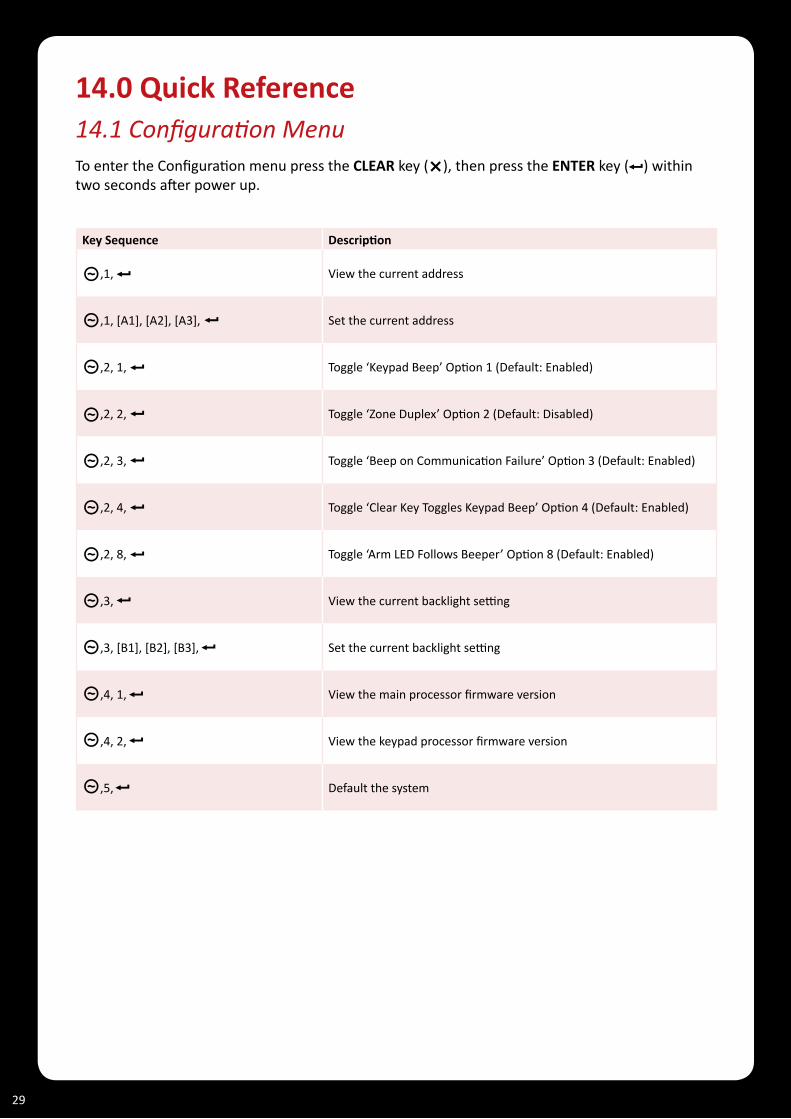
14.0 Quick Reference 14.1ConfigurationMenu To enter the Configuration menu press the CLEAR key ( ), then press the ENTER key ( ) within two seconds after power up.
Key Sequence Description
,1, View the current address
,1, [A1], [A2], [A3], Set the current address
,2, 1, Toggle ‘Keypad Beep’ Option 1 (Default: Enabled)
,2, 2, Toggle ‘Zone Duplex’ Option 2 (Default: Disabled)
,2, 3, Toggle ‘Beep on Communication Failure’ Option 3 (Default: Enabled)
,2, 4, Toggle ‘Clear Key Toggles Keypad Beep’ Option 4 (Default: Enabled)
,2, 8, Toggle ‘Arm LED Follows Beeper’ Option 8 (Default: Enabled)
,3, View the current backlight setting
,3, [B1], [B2], [B3], Set the current backlight setting
,4, 1, View the main processor firmware version
,4, 2, View the keypad processor firmware version
,5, Default the system
29

15.0 Mechanical DiagramThe mechanical diagram shown below outlines the essential details needed to help ensure the correct installation of the Protégé® Eclipse LED Keypad.
Tamper Switch
Case Disassembly Tab
Mounting Holes
Wiring Loom Socket
Figure 20 - Mechanical Diagram
Arm/Armed
Error Code Indicator
Power/Trouble
Disarmed
Message
Alarm Memory
Zone/Error Code Indicators
30

16.0 Technical Diagram The technical diagram shown below outlines the essential details needed to help ensure the correct installation of the Protégé® Eclipse LED Keypad.
40mm4.5mm diameter
54mm
PRT-KLES
16.5mm
10mm
10.5mm
17.5mm
37.5mm
57.5mm
64.5mm
75mm
34.5mm
82.5mm
100.5mm
107mm
117mm97
mm
48m
m
Figure 21 - Technical Diagram
31

17.0 Technical SpecificationsThe following technical specifications are important and vital to the correct operation of the Protégé® Eclipse LED Keypad. Failure to adhere to the technical specifications will result in any warranty or guarantee that was provided becoming NULL AND VOID.
Integrated Control Technology continually strives to increase the performance of its products and as a result the specifications may change without notice. It is recommended that you always consultwww.incontrol.co.nzforthelatestdocumentationandproductinformation.
Operating Voltage 11.5VDC to 24VDC
Operating Current 50mA (80mA max)
User Interface Display/Keypad Combined 15 key capacitive touch keypad with 10x zone status LEDs and 6x system status LEDs.
Zone Inputs (System Zones) 4 using standard or duplexed mode.
Zone Inputs (Enclosure Tamper) PCB mounted external micro switch assembly.
PGM Outputs 1x open collector output for general functions (negative output, 50mA max).
Display and Audible Functions Armed, ready and beeper
Operating Temperature 5˚ to 55˚C (41˚ to 131˚F)
Storage Temperature -10˚ to 85˚C (14˚ to 185˚F)
Humidity 0% to 85% (Non condensing)
Dimensions (H x W x D) 118 x 75 x 19mm (4.65 x 2.95 x 0.9”)
Weight 148g (5.23oz)
Specifications are subject to change without notice, please visit www.incontrol.co.nz for updated information.
32

18.0 Ordering InformationPlease use the following product codes when placing an order for the Protégé® Eclipse LED Keypad.
• PRT-KLES
Manuals and literature are available at the Integrated Control Technology website in the documentationsection.IfyourequiremanualsonCD-ROMpleaserequestaResourceCD-ROMfrom the website.
33

19.0 WarrantyThe Seller warrants its products to be free from defects in materials and workmanship under normal use for a period of one year. Except as specifically stated herein, all express or implied warranties whatsoever, statutory or otherwise, including without limitation, any implied warranty of merchantability and fitness for a particular purpose, are expressly excluded. The Seller does not install or connect the products and because the products may be used in conjunction with products not manufactured by the Seller, the Seller cannot guarantee the performance of the security system. Seller’s obligation and liability under this warranty is expressly limited to repairing or replacing, at Seller’s option, any product not meeting the specifications. In no event shall the Seller be liable to the buyer or any other person for any loss or damages whether direct or indirect or consequential or incidental, including without limitation, any damages for lost profits, stolen goods, or claims by any other party caused by defective goods or otherwise arising from the improper, incorrect or otherwise faulty installation or use of the merchandise sold.
Protégé® and the Protégé® Logo are registered trademarks of Integrated Control Technology Limited.
34

This page has been intentionally left blank

This page has been intentionally left blank

Integrated Control Technology Limited11 Canaveral Drive, Albany, North Shore City 0632, Auckland, New Zealand
P.O. Box 302-340, North Harbour, Auckland, New Zealand Phone: +64 (9) 476 7124
Fax: +64 (9) 476 7128 Email: [email protected]
www.incontrol.co.nz
Designers and manufacturers of integrated electronic access control, security and building automation products. Designed and manufactured by Integrated Control Technology Limited.
© Copyright Integrated Control Technology Limited 2003-2010. All rights reserved.
227-4190-021