protecting our water resources since 1982 aquistar pt2x ... pt2x smart... · aquistar pt2x smart...
TRANSCRIPT

INSTRUMENTATION NORTHWEST, INC.
AquiStar PT2XSmart SensorPressure/TemperatureSensor and Datalogger
Including PT2X-BVBarometric/Vacuum Sensor
INSTRUCTIONMANUAL
®
InstrumentationNorthwest, Inc.
Protecting our water resources since 1982

1
Table of ContentsIntroduction ..................................................................................................................... 3
What is the PT2X? .................................................................................................... 3Initial Inspection and Handling ................................................................................ 3Do’s and Don’ts ....................................................................................................... 3
How Pressure Sensors Work ........................................................................................... 4Installation ....................................................................................................................... 6
Installing the Sensor ................................................................................................. 6Connecting External Power ....................................................................................... 7Installing the Aqua4Plus Software ............................................................................ 7Connecting the PT2X to a Computer ........................................................................ 8
Maintenance .................................................................................................................... 8Changing Batteries ................................................................................................... 8Desiccant Tubes ...................................................................................................... 10Recalibration and Check-up ..................................................................................... 10Miscellaneous ......................................................................................................... 10
Trouble Shooting ............................................................................................................ 11Erratic Readings ....................................................................................................... 11Oscillating Readings Over Time .............................................................................. 11Zero Readings When Pressurized ........................................................................... 11Grounding Issues .................................................................................................... 12
Appendix A: Technical Specifications ............................................................................ 13General Specification ............................................................................................... 13Wiring and Component Information ........................................................................ 13Operating Specifications .......................................................................................... 15Mechanical Specifications ....................................................................................... 15Battery Life Calculation ........................................................................................... 16
Appendix B: Field Calibration (Pressure) ........................................................................ 17Appendix C: Measuring Elevation or Depth-to-Water ................................................... 19
Measuring Depth-to-Water ..................................................................................... 19Measuring Groundwater Elevation .......................................................................... 20
Appendix D: Using USB to Serial Cables ........................................................................ 21Appendix E: PT2X-BV Barometric/Vacuum Sensor ......................................................... 22
What is the PT2X-BV? ............................................................................................. 22Software ................................................................................................................... 22Connecting the PT2X-BV to a Computer ................................................................. 23Recalibration and Check-up ..................................................................................... 23Changing Batteries .................................................................................................. 23Operating and Mechanical Specifications ............................................................... 24
Reordering Information ................................................................................................... 25Limited Warranty/Disclaimer-AquiStar® PT2X .............................................................. 26

2
Information in this document is subject to change without notice and does not representa commitment on the part of the manufacturer. No part of this manual may bereproduced or transmitted in any form or by any means, electronic or mechanical,including photocopying and recording, for any purpose without the express writtenpermission of the manufacturer.
©1997 - 2004 Instrumentation Northwest, Inc.Registered trademarks and trademarks belong to their respective owners.
3Introduction
What is the PT2X?
INW’s AquiStar® PT2X Smart Sensor is a submersible pressure/temperature sensor anddatalogger combined in one small diameter unit. This industry standard digital RS485interface device records over 130,000 records of pressure, temperature and time data,operates with low power, and features easy-to-use software with powerful features.
The PT2X is powered internally with two AA batteries or with an auxiliary powersupply for data intensive applications. The unit is programmed using a laptop ordesktop Windows® based computer via its RS485/RS232 connector and easy to useAqua4Plus software. Once programmed the unit will measure and collect data on avariety of time intervals.
The AquiStar® PT2X can be used to replace analog sensors hooked to separatedataloggers. The MODBUS® interface protocol can be used for RTU and PLC applica-tions. (See factory for details. ) Units can be used to monitor groundwater, well, tankand tidal levels, as well as for pump testing and flow monitoring.
Initial Inspection and Handling
Upon receipt of your smart sensor, inspect the shipping package for damage. If anydamage is apparent, note the signs of damage on the appropriate shipping form. Afteropening the carton, look for concealed damage, such as a cut cable. If concealeddamage is found, immediately file a claim with the carrier.
Check the etched label on the sensor to be sure that the proper range and type wereprovided. Also check the label attached to the cable at the connector end for the propercable length.
Do’s and Don’ts
Do handle the device with care.Do store the device in a dry, inside area when not in use.Do install a desiccant tube if you are doing long-term outdoor monitoring.
Don’t install the device so that the connector end is submerged.Don’t support the device with the connector or with the connectors of an extension
cable. Use a strain relief device to take the tension off the connectors.Don’t allow the device to free-fall down a well at high velocities as impact damage
can occur.Don’t bang or drop the device on hard objects.
4How Pressure Sensors WorkThe following paragraphs outline the basics of how pressure is measured usingsubmersible pressure sensors:
Liquids and gasses do not retain a fixed shape. Both have the ability to flow and areoften referred to as fluids. One fundamental law for a fluid is that the fluid exerts anequal pressure in all directions at a given level. Further, this pressure increases with anincreasing depth of “submergence”. If the density of a fluid remains constant(noncompressible...a generally good assumption for water at “normal” pressures andtemperatures), this pressure increases linearly with the depth of “submergence”.
We are all “submerged” in the atmosphere. As we increase our elevation, the pressureexerted on our bodies decreases as there is less of this fluid above us. It should benoted that atmospheric pressure at a given level does vary with changes in the weather.One standard atmosphere (pressure at sea level at 20º C) is defined to be 14.7 PSI(pounds per square inch).
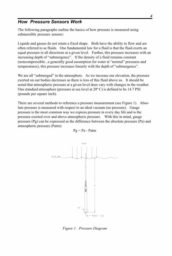
There are several methods to reference a pressure measurement (see Figure 1). Abso-lute pressure is measured with respect to an ideal vacuum (no pressure). Gaugepressure is the most common way we express pressure in every day life and is thepressure exerted over and above atmospheric pressure. With this in mind, gaugepressure (Pg) can be expressed as the difference between the absolute pressure (Pa) andatmospheric pressure (Patm):
Pg = Pa - Patm
Figure 1: Pressure Diagram
5To measure gauge pressure, atmospheric pressure is subjected to one side of the systemand the pressure to be measured is subjected to the other. The result is that the differen-tial (gauge pressure) is measured. A tire pressure gauge is a common example of thistype of device.
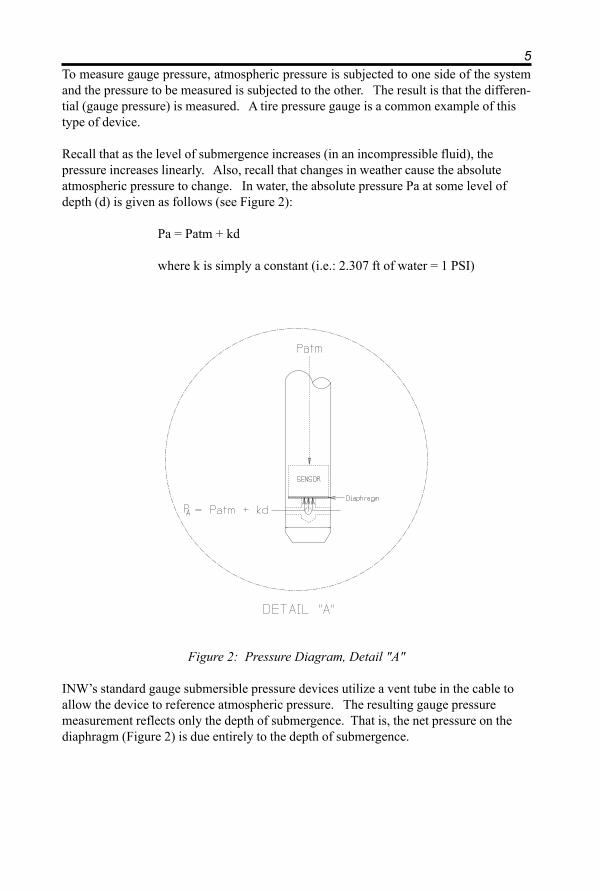
Recall that as the level of submergence increases (in an incompressible fluid), thepressure increases linearly. Also, recall that changes in weather cause the absoluteatmospheric pressure to change. In water, the absolute pressure Pa at some level ofdepth (d) is given as follows (see Figure 2):
Pa = Patm + kd
where k is simply a constant (i.e.: 2.307 ft of water = 1 PSI)
Figure 2: Pressure Diagram, Detail "A"
INW’s standard gauge submersible pressure devices utilize a vent tube in the cable toallow the device to reference atmospheric pressure. The resulting gauge pressuremeasurement reflects only the depth of submergence. That is, the net pressure on thediaphragm (Figure 2) is due entirely to the depth of submergence.
6Installation
Installing the Sensor
The PT2X measures pressure. The most common application is measuring liquid levelsin wells and tanks. In order to do this, the sensor must be installed below the waterlevel at a fixed depth. The installation depth depends on the range of the sensor. One(1) PSI is equal to approximately 2.31 feet of water. If you have a 5 PSI sensor, therange is 11.55 feet of water and the sensor should not be installed at a depth below11.55 feet. If the sensor is installed below its maximum range, damage may result tothe sensor and the output reading will not be correct.
Monitoring Wells
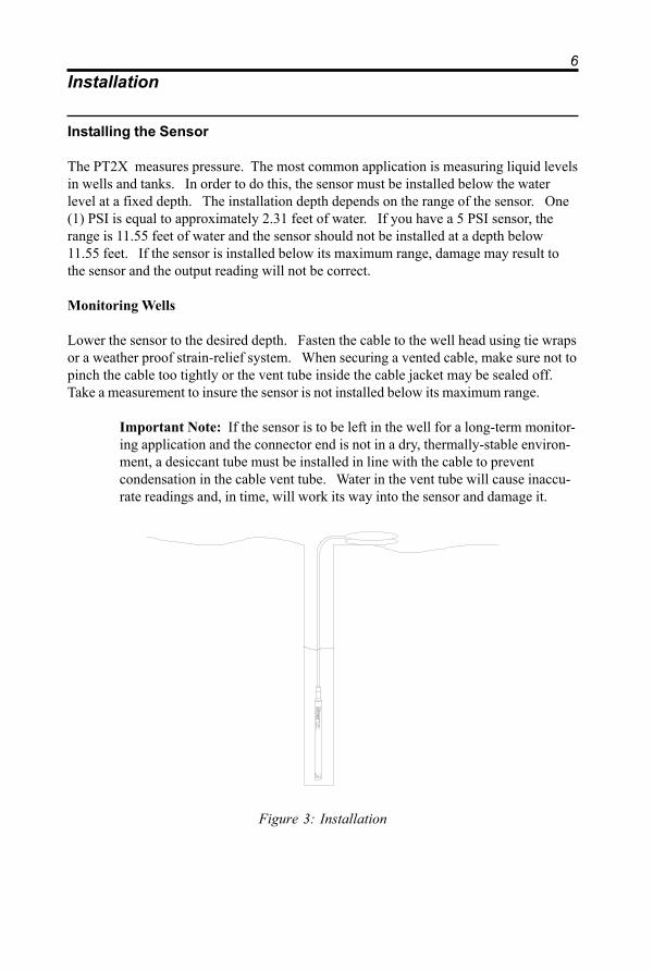
Lower the sensor to the desired depth. Fasten the cable to the well head using tie wrapsor a weather proof strain-relief system. When securing a vented cable, make sure not topinch the cable too tightly or the vent tube inside the cable jacket may be sealed off.Take a measurement to insure the sensor is not installed below its maximum range.
Important Note: If the sensor is to be left in the well for a long-term monitor-ing application and the connector end is not in a dry, thermally-stable environ-ment, a desiccant tube must be installed in line with the cable to preventcondensation in the cable vent tube. Water in the vent tube will cause inaccu-rate readings and, in time, will work its way into the sensor and damage it.
Instru
me
ntatio
n N
orthw
est, Inc
.
PS9
105
0-3
0 PS
IGM
ADE IN RE
DMOND, W
A USA-PA
TENT# 5,033,297
Figure 3: Installation

7Other Installations
The sensor can be installed in any position; however, when it leaves the factory it istested in the vertical position. Strapping the sensor body with tie wraps or tape will nothurt it. INW can provide an optional 1/4" NPT input adapter which is interchangeablewith the standard end cone for those applications where it is necessary to directly attachthe sensor to a pipe, tank or other pipe port (see Figure 3). If the sensor is beinginstalled in a fluid environment other than water, be sure to check the compatibility ofthe fluid with the wetted parts of the sensor. INW can provide a variety of seal materi-als if you are planning to install the sensor in an environment other than water.
Connecting External Power
The PT2X comes with two AA internal batteries. This provides enough power for atleast one year of operation at the rate of four measurements per hour. (See Battery LifeCalculation section in Appendix A for further details.)
If auxiliary power is desired, you can use a 6 - 13 VDC supply that can provide 15 ma.Connect to Vaux++ (white) and Ground (blue) or contact INW for auxiliary powerconnectors.
Installing the Aqua4Plus Software
The PT2X comes with the Aqua4Plus host software that is installed on your PC orlaptop. This software is used to program the datalogger, to retrieve data from the logger,to view collected data, and to export data to external files for use with spreadsheets ordatabases.
Refer to the Aqua4Plus software manual for details on installing and using Aqua4Plus.Software is also available for some handheld PDA’s. Contact your sales representativefor details.
Using the PT2X Without Aqua4Plus
For those who want to access the PT2X data via the Modbus protocol and theirown software, please refer to the application note “Converting Raw Data from PT2X andApplying Calibration Values” - available at:
http://www.inwusa.com/pdfs/pt2x_converting_raw_data.pdf
8
Maintenance
Changing Batteries
Because changing the batteries involves opening the water-tight seal, this must bedone in a clean, dry environment to avoid contamination or moisture damage to thecircuitry.
Battery Type
The PT2X uses two standard AA Alkaline batteries. A fresh set of batteries should lastup to one year when taking four samples per hour. For details in calculating battery life,see Appendix A.
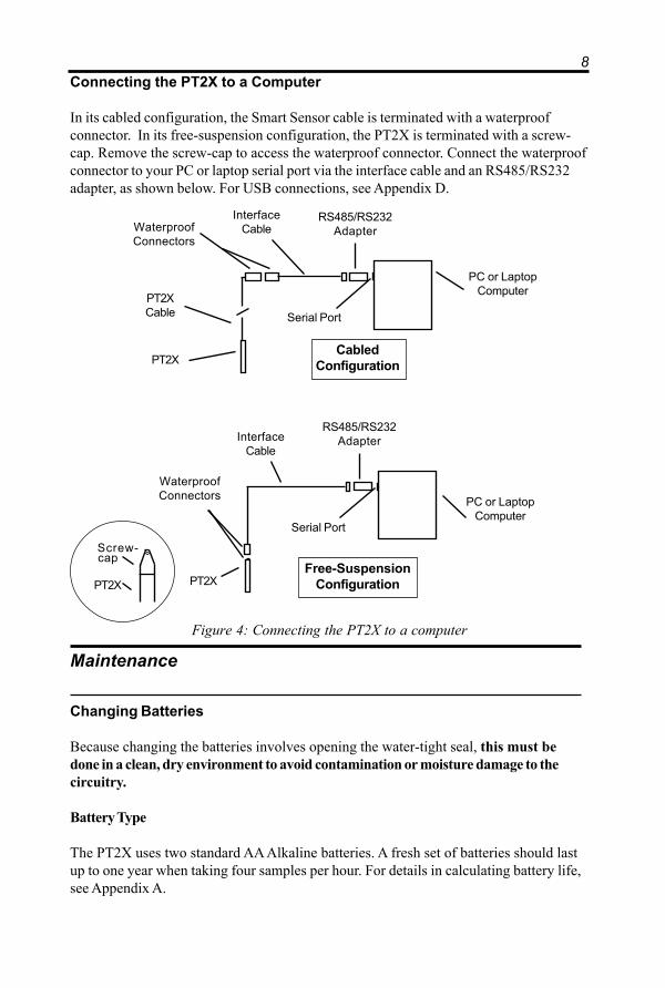
Connecting the PT2X to a Computer
In its cabled configuration, the Smart Sensor cable is terminated with a waterproofconnector. In its free-suspension configuration, the PT2X is terminated with a screw-cap. Remove the screw-cap to access the waterproof connector. Connect the waterproofconnector to your PC or laptop serial port via the interface cable and an RS485/RS232adapter, as shown below. For USB connections, see Appendix D.
Figure 4: Connecting the PT2X to a computer
PC or LaptopComputer
RS485/RS232AdapterInterface
Cable
WaterproofConnectors
Serial Port
PT2X
Screw-
PT2X
capFree-Suspension
Configuration
PC or LaptopComputer
RS485/RS232Adapter
InterfaceCableWaterproof
Connectors
Serial Port
PT2X
PT2XCable
CabledConfiguration

9Replacing the Batteries
Open the housing by removing the top-cap, as outlined below. The top-cap is theconnector between the tube housing the PT2X and the cable. (See figure 7, page 14 forillustration.)
1. Remove the two set screws at the top of the housing tube, using a 1/16” allenwrench.
2. Very gently work the top cap loose. Note, two o-rings provide a water-tight sealfor the PT2X housing and often seal tightly. Inserting the blade of a flat screw-driver between the top-cap and the housing and twisting gently can help torelease the o-rings’ seal. Then rock the top-cap back and forth, while applyingsteady, but controlled, upward pressure.
Caution! Pulling forcefully on the top-cap can cause the O-rings torelease suddenly and the top-cap to disengage with enough force topull the insides out of the sensor or snap the connections inside.Removing the circuit board or pushing on the surface of the pressureelement may void your warranty.
3. Remove the black service connector (Figure 5)4. Tip housing over and gently slide batteries out.5. Insert new batteries - positive terminals towards the top-cap.6. Replace service connector. Note: this connector is keyed and can only be
connected in one direction.7. Carefully wrap the cable around the slot in the connector board.8. Replace top-cap.9. Replace set screws and tighten with a 1/16” allen wrench.
Figure 5: Removing Service Connector
ServiceConnector
10Desiccant Tubes
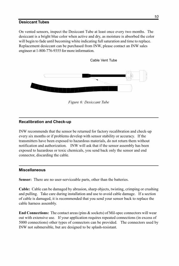
On vented sensors, inspect the Desiccant Tube at least once every two months. Thedesiccant is a bright blue color when active and dry, as moisture is absorbed the colorwill begin to fade until becoming white indicating full saturation and time to replace.Replacement desiccant can be purchased from INW, please contact an INW salesengineer at 1-800-776-9355 for more information.
Cable Vent Tube
Figure 6: Desiccant Tube
Recalibration and Check-up
INW recommends that the sensor be returned for factory recalibration and check-upevery six months or if problems develop with sensor stability or accuracy. If thetransmitters have been exposed to hazardous materials, do not return them withoutnotification and authorization. INW will ask that if the sensor assembly has beenexposed to hazardous or toxic chemicals, you send back only the sensor and endconnector, discarding the cable.
Miscellaneous
Sensor: There are no user-serviceable parts, other than the batteries.
Cable: Cable can be damaged by abrasion, sharp objects, twisting, crimping or crushingand pulling. Take care during installation and use to avoid cable damage. If a sectionof cable is damaged, it is recommended that you send your sensor back to replace thecable harness assembly.
End Connections: The contact areas (pins & sockets) of Mil-spec connectors will wearout with extensive use. If your application requires repeated connections (in excess of5000 connections) other types of connectors can be provided. The connectors used byINW not submersible, but are designed to be splash-resistant.

11Trouble Shooting
Erratic Readings
Erratic readings can be caused by a damaged transmitter, damaged cable, poor connec-tions or improper operation of readout equipment. In most cases, erratic readings aredue to moisture getting into the system. Assuming that the readout equipment isworking correctly, the first thing to check is the connection. Look for moisture betweencontacts or a loose or broken wire. If the connection appears OK, pull the transmitterup a known distance while monitoring its output. If the transmitter responds approxi-mately as it should, but the reading is still erratic, most likely the cable is damaged. Ifthe transmitter does not respond approximately as it should, it is most likely that thesensor is damaged. In either case, consult the factory.
Erratic and erroneous readings can also occur due to improper grounding. See Ground-ing Issues, next page.
Oscillating Readings Over Time
If, after time, your transmitter is functioning normally but your data is showing a cycliceffect in the absence of water level changes, you are probably seeing barometricchanges. The amount is usually .5 to 1.5 feet of water. This can be caused by aplugged vent tube in the cable or actual water level changes in the aquifer itself inresponse to barometric pressure changes. This effect can occur in tight formationswhere the transmitter will immediately pick up barometric changes but the aquifer willnot. If you think you are having this type of problem you will have to record thebarometric pressure as well as the water level pressure and compensate the data. If itappears that the vent tube is plugged, consult the factory.
If a desiccant tube is not installed in line with the cable, water may have condensed inyour vent tube causing it to plug. After you are finished installing the desiccant tubeyou can test the vent tube by applying a small amount of pressure to the end of thedesiccant tube and seeing if this affects the transmitter reading.
Zero Readings When Pressurized
Continuous zero readings are caused by an open circuit which usually indicates brokencable, a bad connection, or possibly a damaged transmitter. Check the connector to seeif a wire has become loose, or if the cable has been cut. If neither of these appears tocause the problem, the transmitter needs factory repair.

12Grounding Issues
It is commonly known that when using electronic equipment, both personnel andequipment need to be protected from high power spikes that may be caused by light-ning, power line surges, or faulty equipment. Without a proper grounding system, apower spike will find the path of least resistance to earth ground – whether that path isthrough sensitive electronic equipment or the person operating the equipment. In orderto ensure safety and prevent equipment damage, a grounding system must be used toprovide a low resistance path to ground.
When using several pieces of interconnected equipment, each of which may have itsown ground, problems with noise, signal interference, and erroneous readings may benoted. This is caused by a condition known as a Ground Loop. Because of naturalresistance in the earth between the grounding points, current can flow between thepoints, creating an unexpected voltage difference and resulting erroneous readings.
The single most important step in minimizing a ground loop is to tie all equipment(sensors, dataloggers, external power sources and any other associated equipment) to asingle common grounding point. INW recommends connecting the shield to ground atthe connector end.

13Appendix A: Technical Specifications
General SpecificationThe AquiStar® PT2X is a microprocessor based digital intelligent sensor designed tomeasure and record pressure, temperature and time, utilizing state-of-the-art low power,battery operated circuitry.
Pressure measurement is accomplished utilizing an extremely rugged and stable piezo-electric media-isolated pressure element combined with a 16-bit delta/sigma analog-to-digital converter. This provides extremely accurate and stable pressure input into themicroprocessor on the circuit board that measures the pressure, stores the data in onemegabyte of on-board eprom, and communicates the information via a serial communi-cation link (RS485) to the host computer.
Temperature measurement is accomplished utilizing a temperature sensor chip, and timeis measured utilizing a real-time clock chip with battery backup.
Because of advancements in surface mount chip technology, INW has been able tocreate a circuit that is only 2” long by .65” wide and will run using two AA batteries for59 weeks*. The compact size of this circuit compresses technology into a size thatallows this circuit and two AA batteries to fit in our analog sensor packaging, whichprovides an upgrade path for existing PS9800 customers.
* Using fresh batteries, taking readings every 15 minutes and uploading the data once aweek to a host computer.
Wiring and Component Information
PT2X Wiring Information:
Cable Type: 9-conductor, ventedShield = GroundWhite = Vaux (5.5 to 15 VDC)Brown = Digital outOrange = Vbat+ (1.8 to 3.3 VDC)Blue = GroundYellow = Comm D+Purple = Comm D-
14
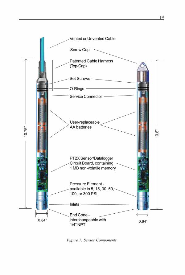
Figure 7: Sensor Components
10.6
”
10.7
5”
0.84” 0.84”
End Cone -interchangeable with1/4” NPT
Pressure Element -available in 5, 15, 30, 50,100, or 300 PSI
PT2X Sensor/DataloggerCircuit Board, containing1 MB non-volatile memory
User-replaceableAA batteries
Service Connector
Patented Cable Harness(Top-Cap)
Vented or Unvented Cable
Inlets
O-Rings
Set Screws
Screw Cap
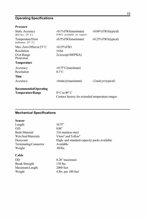
15Operating Specifications
PressureStatic Accuracy ±0.1% FSO (maximum) ±0.06% FSO (typical)(B.F.S.L. 25° C) 0.06% available on request
Temperature Error ±0.5% FSO (maximum) ±0.25% FSO (typical)(reference 25° C)
Max. Zero Offset at 25° C ±0.25% FSOResolution 16 bitOver Range 2x (except 300 PSIA)ProtectionTemperatureAccuracy ±0.75° C (maximum)Resolution 0.1° CTimeAccuracy ±4 min/yr (maximum) ±2 min/yr (typical)
Recommended OperatingTemperature Range 0° C to 40° C
Contact factory for extended temperature ranges.
Mechanical Specifications
SensorLength: 10.75”O.D. 0.84”Body Material 316 stainless steelWire Seal Materials Viton® and Teflon®
Desiccant High- and standard-capacity packs availableTerminating Connector AvailableWeight .80 lbs.
CableOD 0.28” maximumBreak Strength 138 lbs.Maximum Length 2000 feetWeight 4 lbs. per 100 feet

16Battery Life Calculation
The PT2X has been designed for very low power consumption. When not in active use,the unit goes into a “sleep” mode, waking only to take readings or communicate with thehost computer.
It is difficult to know how fresh particular batteries are. Just sitting on a shelf, especiallyin a warm environment, will cause the batteries to lose energy. If the batteries are storedin a cold environment, the self-discharge will be less, but the batteries won't provide asmuch energy output when they're cold. Under optimum conditions, two fresh AAalkaline batteries should provide 15,000 Joules of energy. To give yourself some margin,INW recommends that you assume approximately 12,000 Joules.
When sleeping, the PT2X consumes approximately 150 Joules per week. Each readingconsumes approximately .075 Joules. Communicating with the sensor for one minute, toupload data or take real-time readings, for instance, consumes approximately two Joules.
Use the following formulas to calculate your battery life:
Compute Weekly usage:Readings usage = number of readings per hour * 24 hours * 7 days * .075 JoulesCommunications usage = minutes of communication per week * 2 JoulesSleep time usage = 150 JoulesTotal weekly usage = reading + communication + sleep usage
Compute life of batteries:Life of batteries in weeks = 12,000 Joules / Total weekly usage
Example:4 readings per hour, 1 minute of communication per week
Readings usage = 4 * 24 hours * 7 days * .075 Joules = 50 JoulesCommunication usage = 1 * 2 Joules = 2 JoulesSleep time usage = 150 JoulesTotal weekly usage = 50 + 2 + 150 = 202 JoulesLife of battery = 12,000 / 202 = 59 weeks (approx.)
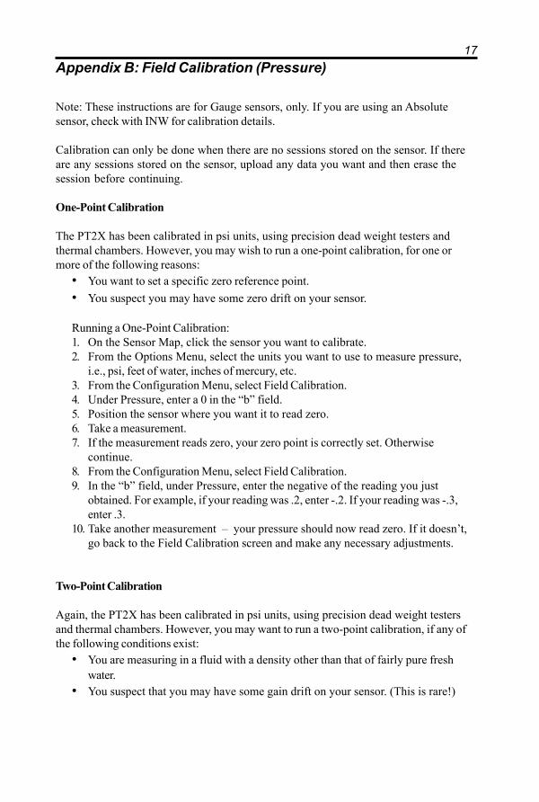
17Appendix B: Field Calibration (Pressure)
Note: These instructions are for Gauge sensors, only. If you are using an Absolutesensor, check with INW for calibration details.
Calibration can only be done when there are no sessions stored on the sensor. If thereare any sessions stored on the sensor, upload any data you want and then erase thesession before continuing.
One-Point Calibration
The PT2X has been calibrated in psi units, using precision dead weight testers andthermal chambers. However, you may wish to run a one-point calibration, for one ormore of the following reasons:
• You want to set a specific zero reference point.• You suspect you may have some zero drift on your sensor.
Running a One-Point Calibration:1. On the Sensor Map, click the sensor you want to calibrate.2. From the Options Menu, select the units you want to use to measure pressure,
i.e., psi, feet of water, inches of mercury, etc.3. From the Configuration Menu, select Field Calibration.4. Under Pressure, enter a 0 in the “b” field.5. Position the sensor where you want it to read zero.6. Take a measurement.7. If the measurement reads zero, your zero point is correctly set. Otherwise
continue.8. From the Configuration Menu, select Field Calibration.9. In the “b” field, under Pressure, enter the negative of the reading you just
obtained. For example, if your reading was .2, enter -.2. If your reading was -.3,enter .3.
10. Take another measurement – your pressure should now read zero. If it doesn’t,go back to the Field Calibration screen and make any necessary adjustments.
Two-Point Calibration
Again, the PT2X has been calibrated in psi units, using precision dead weight testersand thermal chambers. However, you may want to run a two-point calibration, if any ofthe following conditions exist:
• You are measuring in a fluid with a density other than that of fairly pure freshwater.
• You suspect that you may have some gain drift on your sensor. (This is rare!)
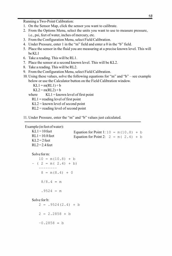
18Running a Two-Point Calibration:1. On the Sensor Map, click the sensor you want to calibrate.2. From the Options Menu, select the units you want to use to measure pressure,
i.e., psi, feet of water, inches of mercury, etc.3. From the Configuration Menu, select Field Calibration.4. Under Pressure, enter 1 in the “m” field and enter a 0 in the “b” field.5. Place the sensor in the fluid you are measuring at a precise known level. This will
be KL16. Take a reading. This will be RL1.7. Place the sensor at a second known level. This will be KL2.8. Take a reading. This will be RL2.9. From the Configuration Menu, select Field Calibration.10. Using these values, solve the following equations for “m” and “b” – see example
below or use the Calculator button on the Field Calibration window. KL1 = m(RL1) + b KL2 = m(RL2) + bwhere KL1 = known level of first point
RL1 = reading level of first pointKL2 = known level of second pointRL2 = reading level of second point
11. Under Pressure, enter the “m” and “b” values just calculated.
Example (in feet of water):KL1 = 10 feetRL1 = 10.8 feetKL2 = 2 feetRL2 = 2.4 feet
Solve for m:10 = m(10.8) + b
- ( 2 = m( 2.4) + b)———————— 8 = m(8.4) + 0
8/8.4 = m
.9524 = m
Solve for b:2 = .9524(2.4) + b
2 = 2.2858 + b
-0.2858 = b
Equation for Point 1: 10 = m(10.8) + bEquation for Point 2: 2 = m( 2.4) + b
19Appendix C: Measuring Elevation or Depth-to-WaterIn normal configuration, the PT2X returns a pressure measurement relative to the waterabove the sensor. This can be expressed in psi, feet of water, inches of mercury, or anumber of other units - however, it is always relative to the water above the sensor.
Often an engineer will need to know the depth-to-water or the elevation of the water.Using Aqua4Plus’ field calibration abilities, the PT2X can be configured to displaydepth-to-water or elevation.
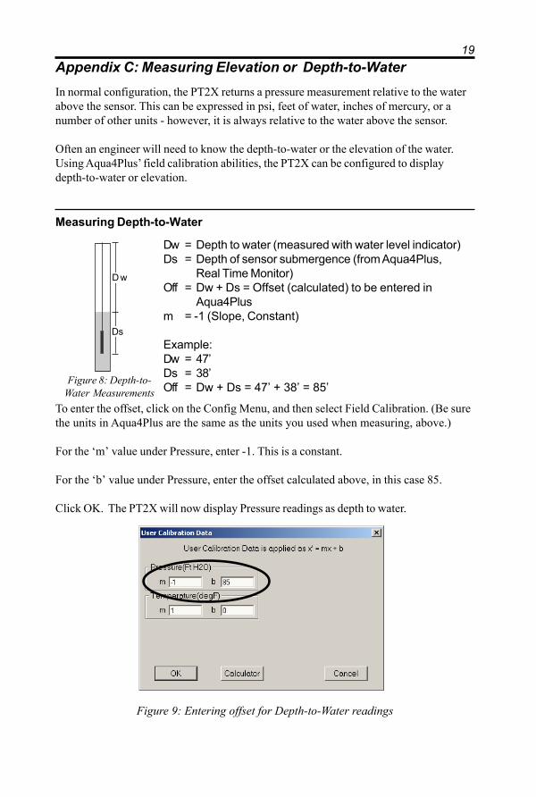
Measuring Depth-to-Water
Dw = Depth to water (measured with water level indicator)Ds = Depth of sensor submergence (from Aqua4Plus,
Real Time Monitor)Off = Dw + Ds = Offset (calculated) to be entered in
Aqua4Plusm = -1 (Slope, Constant)
Example:Dw = 47’Ds = 38’Off = Dw + Ds = 47’ + 38’ = 85’
D w
Ds
To enter the offset, click on the Config Menu, and then select Field Calibration. (Be surethe units in Aqua4Plus are the same as the units you used when measuring, above.)
For the ‘m’ value under Pressure, enter -1. This is a constant.
For the ‘b’ value under Pressure, enter the offset calculated above, in this case 85.
Click OK. The PT2X will now display Pressure readings as depth to water.
Figure 9: Entering offset for Depth-to-Water readings
Figure 8: Depth-to-Water Measurements
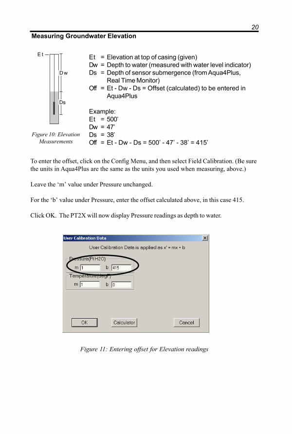
20Measuring Groundwater Elevation
Et = Elevation at top of casing (given)Dw = Depth to water (measured with water level indicator)Ds = Depth of sensor submergence (from Aqua4Plus,
Real Time Monitor)Off = Et - Dw - Ds = Offset (calculated) to be entered in
Aqua4Plus
Example:Et = 500’Dw = 47’Ds = 38’Off = Et - Dw - Ds = 500’ - 47’ - 38’ = 415’
To enter the offset, click on the Config Menu, and then select Field Calibration. (Be surethe units in Aqua4Plus are the same as the units you used when measuring, above.)
Leave the ‘m’ value under Pressure unchanged.
For the ‘b’ value under Pressure, enter the offset calculated above, in this case 415.
Click OK. The PT2X will now display Pressure readings as depth to water.
D w
Ds
E t
Figure 10: ElevationMeasurements
Figure 11: Entering offset for Elevation readings
21
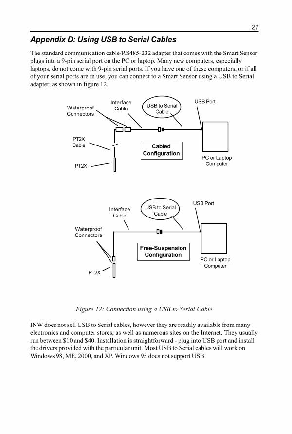
Appendix D: Using USB to Serial CablesThe standard communication cable/RS485-232 adapter that comes with the Smart Sensorplugs into a 9-pin serial port on the PC or laptop. Many new computers, especiallylaptops, do not come with 9-pin serial ports. If you have one of these computers, or if allof your serial ports are in use, you can connect to a Smart Sensor using a USB to Serialadapter, as shown in figure 12.
Figure 12: Connection using a USB to Serial Cable
INW does not sell USB to Serial cables, however they are readily available from manyelectronics and computer stores, as well as numerous sites on the Internet. They usuallyrun between $10 and $40. Installation is straightforward - plug into USB port and installthe drivers provided with the particular unit. Most USB to Serial cables will work onWindows 98, ME, 2000, and XP. Windows 95 does not support USB.
PC or LaptopComputer
USB PortUSB to Serial
CableInterface
Cable
WaterproofConnectors
PT2X
Free-SuspensionConfiguration
InterfaceCableWaterproof
Connectors
PT2X
PT2XCable Cabled
ConfigurationPC or Laptop
Computer
USB PortUSB to Serial
Cable

22Appendix E: PT2X-BV Barometric/Vacuum Sensor
What is the PT2X-BV?
The AquiStar® PT2X-BV is a special version of the PT2X designed to measure baromet-ric and vacuum pressure in reference to absolute pressure, along with temperature andtime.
Pressure measurement is accomplished utilizing an extremely rugged and stable 15 PSIApiezo-electric media-isolated pressure element combined with a 16-bit delta/sigmaanalog-to-digital converter. This provides extremely accurate and stable pressure inputinto the microprocessor on the circuit board that measures the pressure, stores the datain one megabyte of on-board eprom, and communicates the information via a serialcommunication link (RS485) to the host computer.
Temperature measurement is accomplished utilizing a temperature sensor chip, and timeis measured utilizing a real-time clock chip with battery backup.
Barometric MeasurementThe PT2X-BV can be installed in any position; however, it is tested at the factory in theflat position. Therefore, when installing the transmitter outdoors, INW recommendsinstalling it in a flat position to avoid moisture entering the inlet. INW also recommendsinstalling a sun shield to avoid overheating.
Vacuum MeasurementIf installing a vacuum tube for vacuum measurements, be sure that the tubing is notcollapsible. The unit is provided with a detachable Quick-Connect (QC) with a male 1/8”pipe fitting. Attach the tubing to the QC using an appropriate tube fitting for the tubingchosen. Attach a fitting to the inlet male QC designed to seal the tubing of your choice.Seal the fitting to the QC by using sealant or Teflon® tape. Connect the male QC to theinlet QC of the PT2X-BV and the other end of the tube to the vacuum source usingappropriate fittings.
Software
The PT2X-BV is controlled by the Aqua4Plus software in the same way as a regularPT2X. See earlier sections in the manual for detailed software information.
When intending to compare data from the PT2X-BV with that from various PT2X’s, besure to set all clocks to the same time and use the same recording intervals and starttimes. To set the time: connect the sensor to your computer, select the Sensor Clockoption from the Config Menu, and then click the Set From System Clock button. Do thisfor each sensor. To set recording intervals and start times, see Creating a Session, underGetting Started with Aqua4Plus in 6 Easy Steps, earlier in this manual.

23Connecting the PT2X-BV to a Computer
The PT2X-BV comes equipped with a waterproof micro-connector. This can be con-nected to your PC or laptop serial port using the interface cable and RS485/RS232adapter, as shown in Figure 13.
Figure 13: Connecting the PT2X-BV to a computer
PC or LaptopComputer
RS485/RS232Adapter
InterfaceCable
WaterproofMicro-
Connector
SerialPort
PT2X-BV
Quick-ConnectAir/Vacuum Inlet
Recalibration and Check-up
INW recommends that the PT2X-BV be returned for factory recalibration and check-upevery six months or if problems develop with sensor stability or accuracy.
Changing Batteries
Because changing the batteries involves opening the water-resistant seal, it is highlyrecommended that battery changing be done in a clean dry environment.
1. Remove the four screws in the corners of the top cover.2. Remove top cover.3. Gently remove the batteries, taking note of polarity.4. Insert new batteries.5. Replace top cover and screws.

24Operating and Mechanical Specifications
PressureStatic Accuracy ±0.1% FSO (maximum) ±0.06% FSO (typical)(B.F.S.L. 25° C) 0.06% available on request
Temperature Error ±0.5% FSO (maximum) ±0.25% FSO (typical)(reference 25° C)
Max. Zero Offset at 25° C ±0.25% FSOResolution 16 bitOver Range 2 timesProtectionTemperatureAccuracy ±0.75° C (maximum)Resolution 0.1° CTimeAccuracy ±4 min/yr (maximum) ±2 min/yr (typical)
Recommended OperatingTemperature Range 0° C to 40° C
Enclosure Water-resistant ABS plastic4.3” x 3.2” x 2.6” (excluding connectors)

25
Reordering Information
For sales & service offices, please contact:
Instrumentation Northwest, Inc.www.inwusa.com
800-776-9355
26LIMITED WARRANTY/DISCLAIMER - AquiStar® PT2XSUBMERSIBLE PRESSURE /TEMPERATURE SENSOR
A. Seller warrants that products manufactured by Seller when properly installed, usedand maintained with a properly installed desiccant tube, shall be free from defects inmaterial and workmanship. Seller’s obligation under this warranty shall be limited toreplacing or repairing the part or parts or, at Seller’s option, the products which provedefective in material or workmanship within ONE (1) year from the date of delivery,provided that Buyer gives Seller prompt notice of any defect or failure and satisfactoryproof thereof. Any defective part or parts must be returned to Seller’s factory or to anauthorized service center for inspection. Buyer will prepay all freight charges to returnany products to Seller’s factory, or any other repair facility designated by Seller. Sellerwill deliver replacements for defective products to Buyer (ground freight prepaid) tothe destination provided in the original order. Products returned to Seller for whichSeller provides replacement under this warranty shall become the property of Seller.
This limited warranty does not apply to lack of performance caused by abrasive materials,corrosion due to aggressive fluids, mishandling or misapplication. Seller’s obligations underthis warranty shall not apply to any product which (a) is normally consumed in operation, or (b)has a normal life inherently shorter than the warranty period stated herein.
In the event that equipment is altered or repaired by the Buyer without prior written approval bythe Seller, all warranties are void. Equipment and accessories not manufactured by the Sellerare warranted only to the extent of and by the original manufacturer’s warranty.
THE FOREGOING WARRANTIES ARE IN LIEU OF ALL OTHER WARRANTIES,WHETHER ORAL, WRITTEN, EXPRESSED, IMPLIED OR STATUTORY. IMPLIEDWARRANTIES OF FITNESS AND MERCHANTABILITY SHALL NOT APPLY. SELLER’SWARRANTY OBLIGATIONS AND BUYER’S REMEDIES THEREUNDER (EXCEPT AS TOTITLE) ARE SOLELY AND EXCLUSIVELY AS STATED HEREIN. IN NO CASE WILLSELLER BE LIABLE FOR CONSEQUENTIAL DAMAGES, LABOR PERFORMED INCONNECTION WITH REMOVAL AND REPLACEMENT OF THE SENSOR SYSTEM,LOSS OF PRODUCTION OR ANY OTHER LOSS INCURRED BECAUSE OF INTERRUP-TION OF SERVICE. A NEW WARRANTY PERIOD SHALL NOT BE ESTABLISHED FORREPAIRED OR REPLACED MATERIAL, PRODUCTS OR SUPPLIES. SUCH ITEMSSHALL REMAIN UNDER WARRANTY ONLY FOR THE REMAINDER OF THE WAR-RANTY PERIOD ON THE ORIGINAL MATERIALS, PRODUCTS OR SUPPLIES.
B. With respect to products purchased by consumers in the United States for personal use, theimplied warranties including but not limited to the warranties of merchantability and fitness for aparticular purpose, are limited to twelve (12) months from the date of delivery.
Some states do not allow limitations on the duration of an implied warranty, so the abovelimitation may not apply to you. Similarly, some states do not allow the exclusion or limitationof consequential damages, so the above limitation or exclusion may not apply to you. Thislimited warranty gives you specific legal rights; however, you may also have other rights whichmay vary from state to state.

Copyright 1997 - 2004 by Instrumentation Northwest, Inc. All rights reserved.Instrumentation Northwest and INW are trademarks registered with theU.S. Patent & Trademark Office.
Printed on recycled paper.
Doc# 9B00730r6 4/2004 P/N 6D275
Instrumentation Northwest, Inc.8902 122nd Avenue NEKirkland, WA 98033(425) 822-4434 • (425) 822-8384 (fax)(800) 776-9355 • www.inwusa.com
Please visit INW's Web site to learn more about our products and services.
www.inwusa.com
®