prosys lm user's guide - chipkin automation systems
TRANSCRIPT

DEH40109 Installation Instructions
GE Total Lighting ControlProSys™ LM
Lighting Control System Software
User’s Guide
These instructions do not cover all details or variations in equipment nor do they provide for every possible contingency that may be met in connection with installation, operation or maintenance. Should further information be desired or should particular problems arise that are not covered for the purchaser's purposes,the matter should be referred to the GE Company.

ProSys LM User’s Software Guide Document 80-0116 Rev 1.0 1
Table of Contents
System Requirements ..............................................................................................................3
Computer System Requirements ...........................................................................................3
Chapter 1 Devices, Functional Blocks and Plug-ins .............................................................5
Devices ................................................................................................................................5
Functional Blocks.................................................................................................................5
Plug-ins................................................................................................................................5The Configuration Plug-in........................................................................................................... 6
The Viewer Plug-in ..................................................................................................................... 6
Chapter 2 Installing and Setting Up the System.................................................................7
The Steps in Installation and Setup .......................................................................................7Installing the Plug-ins on Your Computer .................................................................................... 7
Opening Existing or Creating New Network .................................... Error! Bookmark not defined.
Registering the Plug-ins ................................................................. Error! Bookmark not defined.
Adding the Devices to the Database................................................ Error! Bookmark not defined.
Commissioning Devices.................................................................. Error! Bookmark not defined.
Accessing Functional Blocks ....................................................................................................... 7
Binding....................................................................................................................................... 7
Software-install and Self-install Modes............................................................................... 10Putting Devices into Self-Install Mode ....................................................................................... 10
Chapter 3 Configuring Lighting Panel Channels .............................................................13
Softwiring a Relay to a Channel ......................................................................................... 13Softwiring a Relay or Relay Group to a Channel ........................................................................ 13
Softwiring a Relay Pattern to a Channel .................................................................................... 14
Setting Time Delay for a Channel ....................................................................................... 15
Setting Flick Warn for a Channel........................................................................................ 14
Assigning Flick Warn to Relays.......................................................................................... 15
Selecting RR9 (Pilot) Relays .............................................................................................. 16
Chapter 4 Scheduling ..........................................................................................................17
Overview ........................................................................................................................... 17
Configuring the Time, the Time Zone and Daylight Savings ............................................... 17
Table of Contents
2 Document 80-0116 Rev 1.0 ProSys LM User’s Software Guide
Setting the Time ........................................................................................................................ 17
Specifying the Time Zone and Location...................................................................................... 18
Setting Daylight Savings Time ................................................................................................... 19
Setting the Network Time Update............................................................................................... 20
Setting Up Daily Schedules ................................................................................................ 20Setting Up an On/Off Schedule .................................................................................................. 21
Setting Up a Manual On/Off Schedule........................................................................................ 21
Setting Up an Astro On/Off Schedule ......................................................................................... 22
Setting Up a Astro On/Scheduled Off Schedule........................................................................... 22
Setting up a Holiday Schedule ................................................................................................... 23
Chapter 5 Configuring ProSys Softwired Switches.......................................................25
Softwiring A Switch’s Buttons ........................................................................................... 25Softwiring a Button to Control Channels.................................................................................... 25
Softwiring a Button to Control One or More Relays ................................................................... 26
Softwiring a Button to Control One or More Relays (to a Pattern) .............................................. 26
Chapter 6 Monitoring a Lighting Network .......................................................................29
The Panel Viewer ............................................................................................................... 29Viewing Lighting Channels........................................................................................................ 29
Changing a Relay’s Status......................................................................................................... 29
The Clock Viewer .............................................................................................................. 30Setting Up the Clock Viewer ...................................................................................................... 30
Index .......................................................................................................................................31

ProSys LM User’s Software Guide Document 80-0116 Rev 1.0 3
Minimum System Requirements
Computer System Requirements
� An LNS-based network management tool that supports plug-ins
� Windows 95, Windows 98, or Windows NT 4.0 with Service Pack 4
� Pentium 133
� 48MB of RAM (64MB recommended) for Windows 95 and 98
� 64MB of RAM (128MB recommended) for Windows NT
� CD-ROM drive
� Mouse or compatible pointing device

ProSys LM User’s Software Guide Document 80-0116 Rev 1.0 5
Chapter 1
Devices, Functional Blocks and Plug-ins
ProSys LM software allows you to configure and operate the lighting control system via threesoftware components: devices, functional blocks and plug-ins.
Devices“ Devices” are software modules that represent the major components of the lighting controlsystem. There are 3 devices in the PoSys LM software package:
� the panel device
� the real time clock device
� the softwired switch device
Functional BlocksFunctional blocks (also known as LonMark Objects) are contained in these devices. Afunctional block represents a collection of network variables and configuration properties of adevice and performs a function for that device. For example, each schedule is represented inthe software by a schedule functional block.
The functional blocks and the devices that contain them are:
The Panel Device
� One Lighting Panel Controller functional block
� Eight Lighting Channel functional blocks
The Real Time Clock Device
� One Real Time Clock functional block
� One Calendar functional block
� Eight Schedule functional blocks
The Softwired Switch Device
� One Softwired Switch functional block
Plug-insPlug-ins are the applications through which you configure, monitor and control the ProSysLM Lighting System. Two plug-ins are installed with ProSys LM:
� The ProSys Configuration Plug-in
� The ProSys Viewer Plug-in

Devices, Functional Blocks and Viewers
6 Document 80-0116 Rev 1.0 ProSys LM User’s Software Guide
The Configuration Plug-inThe configuration plug-in enables you to configure the six functional blocks contained in thethree devices. Functionality includes configuring lighting panels, scheduling, and configuringsoftwired switches. These plug-ins are accessed through the functional blocks.
The Viewer Plug-inThe viewer plug-in has two components:
� The Panel Viewer
� The Clock Viewer
These viewers enable you to see panel and clock settings and to change those settings in realtime. These plug-ins are accessed through their devices. The viewers are described in Chapter6, Monitoring a Lighting Network.
ProSys LM User’s Software Guide Document 80-0116 Rev 1.0 7
Chapter 2
Installation and Setup
The Steps in Installation and SetupThe following seven steps are required before you can configure, monitor and control yourlighting network from your computer. Steps two to six are performed through your networkmanagement tool and described in its documentation.
� ,QVWDOO�WKH�3UR6\V �SOXJ�LQV�RQ�\RXU�FRPSXWHU�
� &UHDWH�D�QHZ�QHWZRUN�RU�RSHQ�WKH�H[LVWLQJ�OLJKWLQJ�QHWZRUN�
� 5HJLVWHU�WKH�SOXJ�LQV�
� $GG�WKH�GHYLFHV�WR�WKH�GDWDEDVH�
� &RPPLVVLRQ�WKH�GHYLFHV�
� $FFHVV�WKH�IXQFWLRQDO�EORFNV�IRU�HDFK�GHYLFH�
� %LQG�QHWZRUN�YDULDEOHV�WRJHWKHU�VR�WKDW�WKH�GHYLFHV�FDQ�FRPPXQLFDWH�ZLWK�HDFKRWKHU�
Installing the Plug-ins on Your ComputerInstall the ProSys LM software from the GE ProSys CD, following the InstallShield Wizardinstructions.
Accessing Functional BlocksAccess the functional blocks that have the characteristics of, and represent, the components ofthe devices they belong to, for instance, the Real Time Clock’s calendar, and schedules.
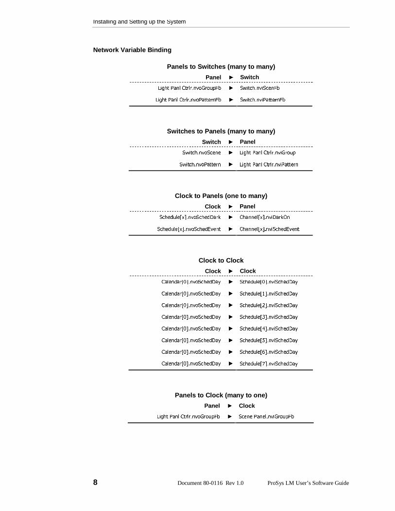
BindingIn order that the clock, switches and panels can communicate with each other, they must beconnected to each other in the software using network variables and message tags. Thisoperation is called binding. All the bindings required to enable a real time clock, panels, andswitches to operate together in a ProSys LM Lighting Control System are listed below.
In the software, the network variable binding connects the functional blocks.
The bindings are documented in the following form: LonMarkObject.NetworkVariable
It is assumed that there is only one clock per network.
Installing and Setting up the System
8 Document 80-0116 Rev 1.0 ProSys LM User’s Software Guide
Network Variable Binding
Panels to Switches (many to many)
Panel Switch
/LJKW�3DQO�&WUOU�QYR*URXS)E����� 6ZLWFK�QYL6FHQ)E
/LJKW�3DQO�&WUOU�QYR3DWWHUQ)E����� 6ZLWFK�QYL3DWWHUQ)E
Switches to Panels (many to many)
Switch Panel
6ZLWFK�QYR6FHQH����� /LJKW�3DQO�&WUOU�QYL*URXS
6ZLWFK�QYR3DWWHUQ����� /LJKW�3DQO�&WUOU�QYL3DWWHUQ
Clock to Panels (one to many)
Clock Panel
6FKHGXOH>[@�QYR6FKHG'DUN����� &KDQQHO>[@�QYL'DUN2Q
6FKHGXOH>[@�QYR6FKHG(YHQW����� &KDQQHO>[@�QYL6FKHG(YHQW
Clock to Clock
Clock Clock
&DOHQGDU>�@�QYR6FKHG'D\����� 6FKHGXOH>�@�QYL6FKHG'D\
&DOHQGDU>�@�QYR6FKHG'D\����� 6FKHGXOH>�@�QYL6FKHG'D\
&DOHQGDU>�@�QYR6FKHG'D\����� 6FKHGXOH>�@�QYL6FKHG'D\
&DOHQGDU>�@�QYR6FKHG'D\����� 6FKHGXOH>�@�QYL6FKHG'D\
&DOHQGDU>�@�QYR6FKHG'D\����� 6FKHGXOH>�@�QYL6FKHG'D\
&DOHQGDU>�@�QYR6FKHG'D\����� 6FKHGXOH>�@�QYL6FKHG'D\
&DOHQGDU>�@�QYR6FKHG'D\����� 6FKHGXOH>�@�QYL6FKHG'D\
&DOHQGDU>�@�QYR6FKHG'D\����� 6FKHGXOH>�@�QYL6FKHG'D\
Panels to Clock (many to one)
Panel Clock
/LJKW�3DQO�&WUOU�QYR*URXS)E����� 6FHQH�3DQHO�QYL*URXS)E
Installing and Setting up the System
Document 80-0116 Rev 1.0 9
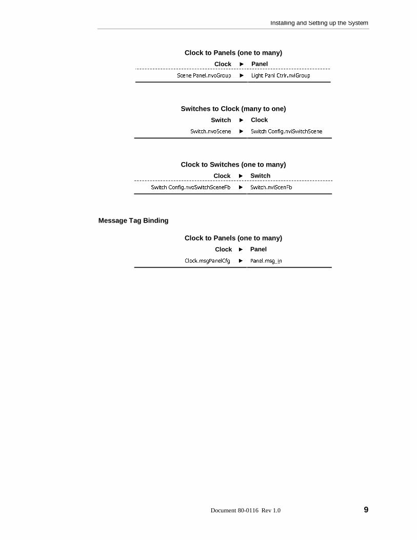
Clock to Panels (one to many)
Clock Panel
6FHQH�3DQHO�QYR*URXS����� /LJKW�3DQO�&WUOU�QYL*URXS
Switches to Clock (many to one)
Switch Clock
6ZLWFK�QYR6FHQH����� 6ZLWFK�&RQILJ�QYL6ZLWFK6FHQH
Clock to Switches (one to many)
Clock Switch
6ZLWFK�&RQILJ�QYR6ZLWFK6FHQH)E����� 6ZLWFK�QYL6FHQ)E
Message Tag Binding
Clock to Panels (one to many)
Clock Panel
&ORFN�PVJ3DQHO&IJ����� 3DQHO�PVJBLQ

Installing and Setting up the System
10 Document 80-0116 Rev 1.0 ProSys LM User’s Software Guide
Software-install and Self-install ModesDevices (panels, softwired switches, and real time clock) in a ProSys LM Lighting Control
System are in software-install mode, which means that in order to be able to communicatethey must be linked in the software by network variable binding. The devices in a stand-aloneProSys Lighting Control System (operated without a computer) are in self-install mode,which means that as soon as they are connected to the network they can communicate witheach other—no binding required.
If, for any reason you need to put devices into self-install mode, the instructions are givenbelow.
WARNING: Before you put devices in self-install mode, be aware that when you return them tosoftware-install mode (to control them through your PC) all the bindings will be lost. You willtherefore have to repeat the binding procedure.
Putting Devices into Self-Install ModeIf a clock, panel or switch is in software-install mode and you want to put the device into self-install mode, press and hold its service pin. The procedure is slightly different for each device(see below).
ClockTo put the Softwired Clock into self-install mode:
1 Press and hold down the service pin.
The screen will go blank.
2 When the screen re-forms release the service pin.
The clock is now in self-install mode.
PanelTo put a Panel into self-install mode:
1 Press and hold down the service pin.
The service pin’s flashing green LED will stop flashing; half of the LED will turn solid red and theother half will flash green.
2 When the LED stops flashing and turns to solid green (after about 10 seconds), release the servicepin.
The panel is now in self-install mode.
SwitchTo put a Switch into self-install mode:
1 Press and hold down the softwire button.
The button LEDs will start flashing.

Installing and Setting up the System
Document 80-0116 Rev 1.0 11
2 When the button LEDs and the locator LED turn off (after about 10 seconds), release the softwirebutton.
When the panel finds the switch, the locator LED will come back on and the switch will be inself-install mode.

ProSys LM User’s Software Guide Document 80-0116 Rev 1.0 13
Chapter 3
Configuring Lighting Panel Channels
Softwiring a Relay to a ChannelA lighting panel’s channel can be softwired to control:
� any relay or group of relays
� any group of relays to a pattern
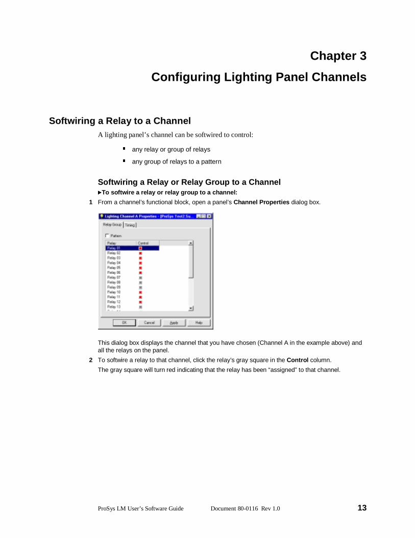
Softwiring a Relay or Relay Group to a ChannelTo softwire a relay or relay group to a channel:
1 From a channel’s functional block, open a panel’s Channel Properties dialog box.
This dialog box displays the channel that you have chosen (Channel A in the example above) andall the relays on the panel.
2 To softwire a relay to that channel, click the relay’s gray square in the Control column.
The gray square will turn red indicating that the relay has been “assigned” to that channel.
Configuring Lighting Panel Channels
14 Document 80-0116 Rev 1.0 ProSys LM User’s Software Guide
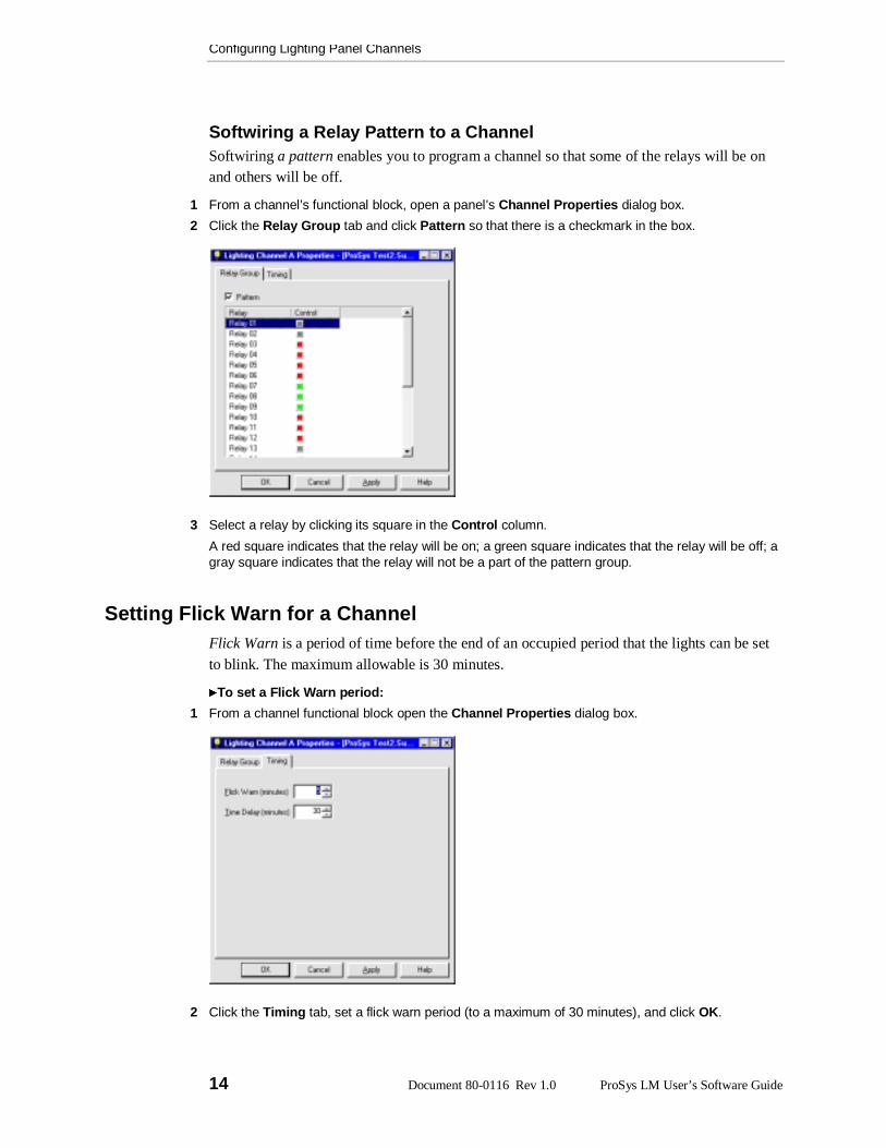
Softwiring a Relay Pattern to a ChannelSoftwiring a pattern enables you to program a channel so that some of the relays will be onand others will be off.
1 From a channel’s functional block, open a panel’s Channel Properties dialog box.
2 Click the Relay Group tab and click Pattern so that there is a checkmark in the box.
3 Select a relay by clicking its square in the Control column.
A red square indicates that the relay will be on; a green square indicates that the relay will be off; agray square indicates that the relay will not be a part of the pattern group.
Setting Flick Warn for a ChannelFlick Warn is a period of time before the end of an occupied period that the lights can be setto blink. The maximum allowable is 30 minutes.
To set a Flick Warn period:
1 From a channel functional block open the Channel Properties dialog box.
2 Click the Timing tab, set a flick warn period (to a maximum of 30 minutes), and click OK.
Configuring Lighting Panel Channels
Document 80-0116 Rev 1.0 15
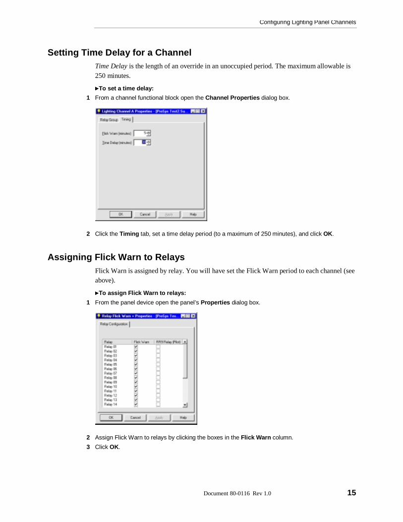
Setting Time Delay for a ChannelTime Delay is the length of an override in an unoccupied period. The maximum allowable is250 minutes.
To set a time delay:
1 From a channel functional block open the Channel Properties dialog box.
2 Click the Timing tab, set a time delay period (to a maximum of 250 minutes), and click OK.
Assigning Flick Warn to RelaysFlick Warn is assigned by relay. You will have set the Flick Warn period to each channel (seeabove).
To assign Flick Warn to relays:
1 From the panel device open the panel’s Properties dialog box.
2 Assign Flick Warn to relays by clicking the boxes in the Flick Warn column.
3 Click OK.

Configuring Lighting Panel Channels
16 Document 80-0116 Rev 1.0 ProSys LM User’s Software Guide
Selecting RR9 (Pilot) RelaysThis dialog box enables you to select the relays that are type RR9 so that any relaymalfunction will show up on the panel. In this dialog box, if you check all the relays that areRR9, when there is a discrepancy between the panel status and the relay state (for example,the relay is on but the panel is reading it as off) the relay’s LED on the panel will turn solidgreen.
To select RR9 relays:
1 From the Panel device open the panel’s Properties dialog box.
2 Indicate the RR9 relays by clicking the boxes in the RR9 Relay column.
3 Click OK.

ProSys LM User’s Software Guide Document 80-0116 Rev 1.0 17
Chapter 4
Scheduling
OverviewSchedules are stored in the Real Time Clock. When working online, when you configure andsave the schedules they are sent to the Real Time Clock, (the clock must be connected to apanel or a switch on the network.)
The main steps in setting up schedules for a lighting network are:
� 6HWWLQJ�WKH�WLPH�IRU�WKH�QHWZRUN
� 6SHFLI\LQJ�WKH�WLPH�]RQH�DQG�ORFDWLRQ�RI�WKH�QHWZRUN
� 6HWWLQJ�GD\OLJKW�VDYLQJV
� 6HWWLQJ�WKH�QHWZRUN�XSGDWH�UDWH
� &RQILJXULQJ�VFKHGXOHV
� &RQILJXULQJ�KROLGD\�VFKHGXOHV
Configuring the Time, the Time Zone and Daylight SavingsBefore you can start scheduling you must set the time, enter the location of the network andthe dates of daylight savings. This ensures that lighting system can perform daily routines in asynchronized fashion through seasonal changes.
Setting the TimeThe time is set through the Clock Viewer.
To set the time:
1 Open the Clock Viewer.
2 Click Adjust Date/Time.
Scheduling
18 Document 80-0116 Rev 1.0 ProSys LM User’s Software Guide
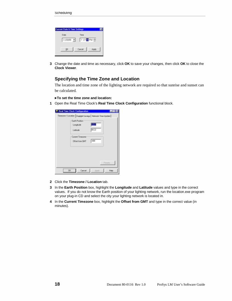
3 Change the date and time as necessary, click OK to save your changes, then click OK to close theClock Viewer.
Specifying the Time Zone and LocationThe location and time zone of the lighting network are required so that sunrise and sunset canbe calculated.
To set the time zone and location:
1 Open the Real Time Clock’s Real Time Clock Configuration functional block.
2 Click the Timezone / Location tab.
3 In the Earth Position box, highlight the Longitude and Latitude values and type in the correctvalues. If you do not know the Earth position of your lighting network, run the location.exe programon your plug-in CD and select the city your lighting network is located in.
4 In the Current Timezone box, highlight the Offset from GMT and type in the correct value (inminutes).
Scheduling
Document 80-0116 Rev 1.0 19
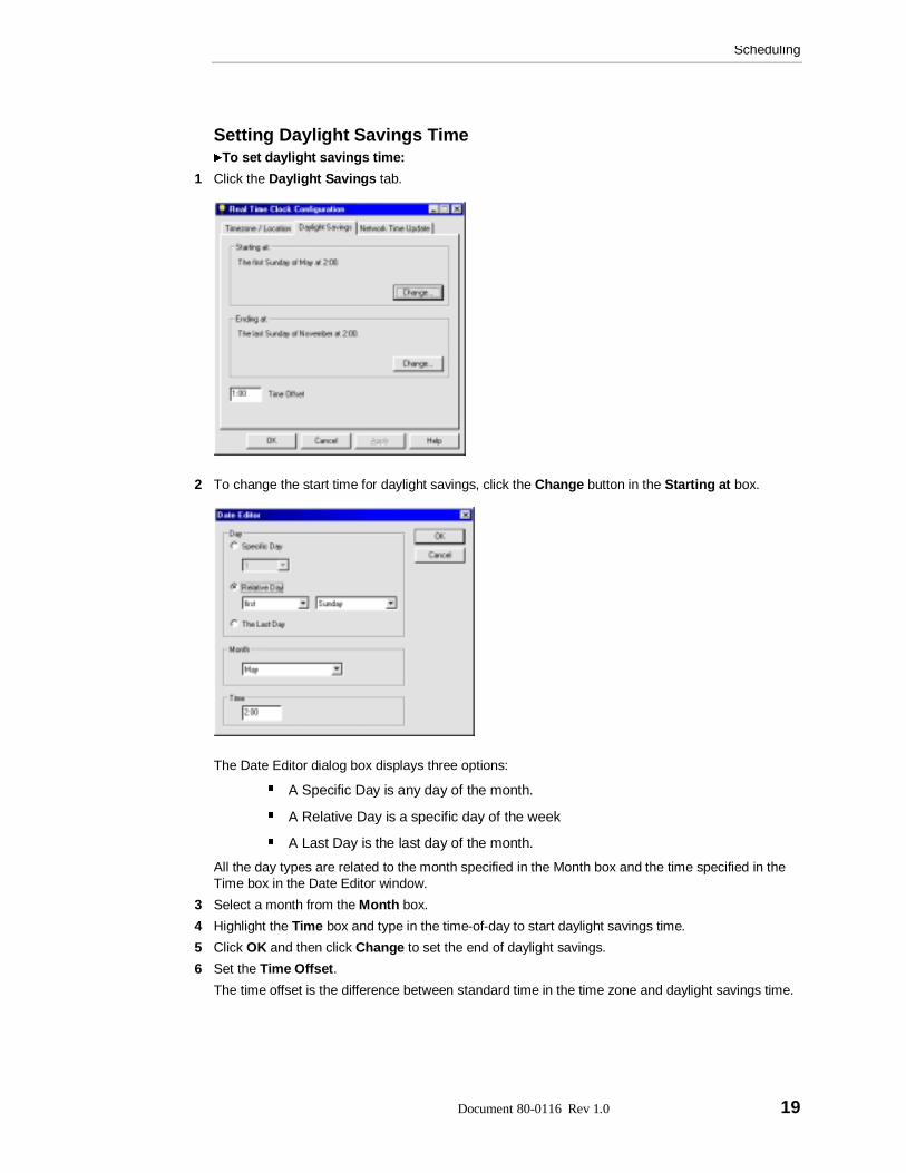
Setting Daylight Savings TimeTo set daylight savings time:
1 Click the Daylight Savings tab.
2 To change the start time for daylight savings, click the Change button in the Starting at box.
The Date Editor dialog box displays three options:
� A Specific Day is any day of the month.
� A Relative Day is a specific day of the week
� A Last Day is the last day of the month.
All the day types are related to the month specified in the Month box and the time specified in theTime box in the Date Editor window.
3 Select a month from the Month box.
4 Highlight the Time box and type in the time-of-day to start daylight savings time.
5 Click OK and then click Change to set the end of daylight savings.
6 Set the Time Offset.
The time offset is the difference between standard time in the time zone and daylight savings time.
Scheduling
20 Document 80-0116 Rev 1.0 ProSys LM User’s Software Guide
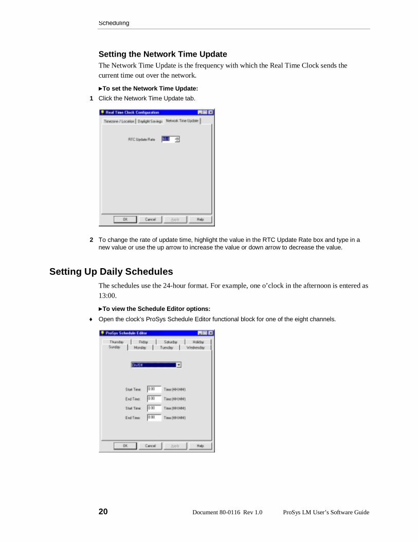
Setting the Network Time UpdateThe Network Time Update is the frequency with which the Real Time Clock sends thecurrent time out over the network.
To set the Network Time Update:
1 Click the Network Time Update tab.
2 To change the rate of update time, highlight the value in the RTC Update Rate box and type in anew value or use the up arrow to increase the value or down arrow to decrease the value.
Setting Up Daily SchedulesThe schedules use the 24-hour format. For example, one o’clock in the afternoon is entered as13:00.
To view the Schedule Editor options:
♦ Open the clock’s ProSys Schedule Editor functional block for one of the eight channels.
Scheduling
Document 80-0116 Rev 1.0 21
Each channel may assigned any one of the four following automation scenarios:
� On/Off is for interior lighting that is automatically turned on during scheduledoccupied hours, and automatically turned off during scheduled unoccupied hours.
� Manual On/ Off is for interior lighting that is turned on by a person during occupiedhours and turned off automatically during scheduled unoccupied hours.
� Astro On/Off is for exterior lighting (security) that uses the Real Time Clock datafor sunrise and sunset times. The exterior lighting turns on and off automaticallybased on these times.
� Astro On/Scheduled Off is for exterior lighting (for parking lots and signage) thatuses sunrise and sunset data from the Real Time Clock and scheduled occupiedtimes to turn on and off automatically.
Setting Up an On/Off ScheduleUse the procedure below for setting up a schedule for every day of the week and for aholiday.
To set up an On/Off schedule for a day of the week:
1 In the Schedule Editor click the down arrow and select the On/Off scenario.
2 Highlight the Start Time and type the time.
Remember to use the 24-hour clock (I:00 pm would be 13:00).
3 Click Apply to send that day’s schedule to the clock, and then click the next day to be scheduled.
There are two Start Time options and two End Time options. This enables you to schedule twodifferent lighting periods for one day.
Setting Up a Manual On/Off ScheduleManual On/Off is for interior lighting that is turned on by a person during occupied hours andturned off automatically during scheduled unoccupied hours.
To set up a Manual On/Off schedule for a day of the week:
1 In the Schedule Editor click the down arrow and select Manual On/Off.
2 Highlight the start and end times and type the times.
3 Click Apply to send that day’s schedule to the clock, and then click the next day to be scheduled.
There are two Start Time options and two End Time options. This enables you to schedule twodifferent lighting periods for one day.
Scheduling
22 Document 80-0116 Rev 1.0 ProSys LM User’s Software Guide
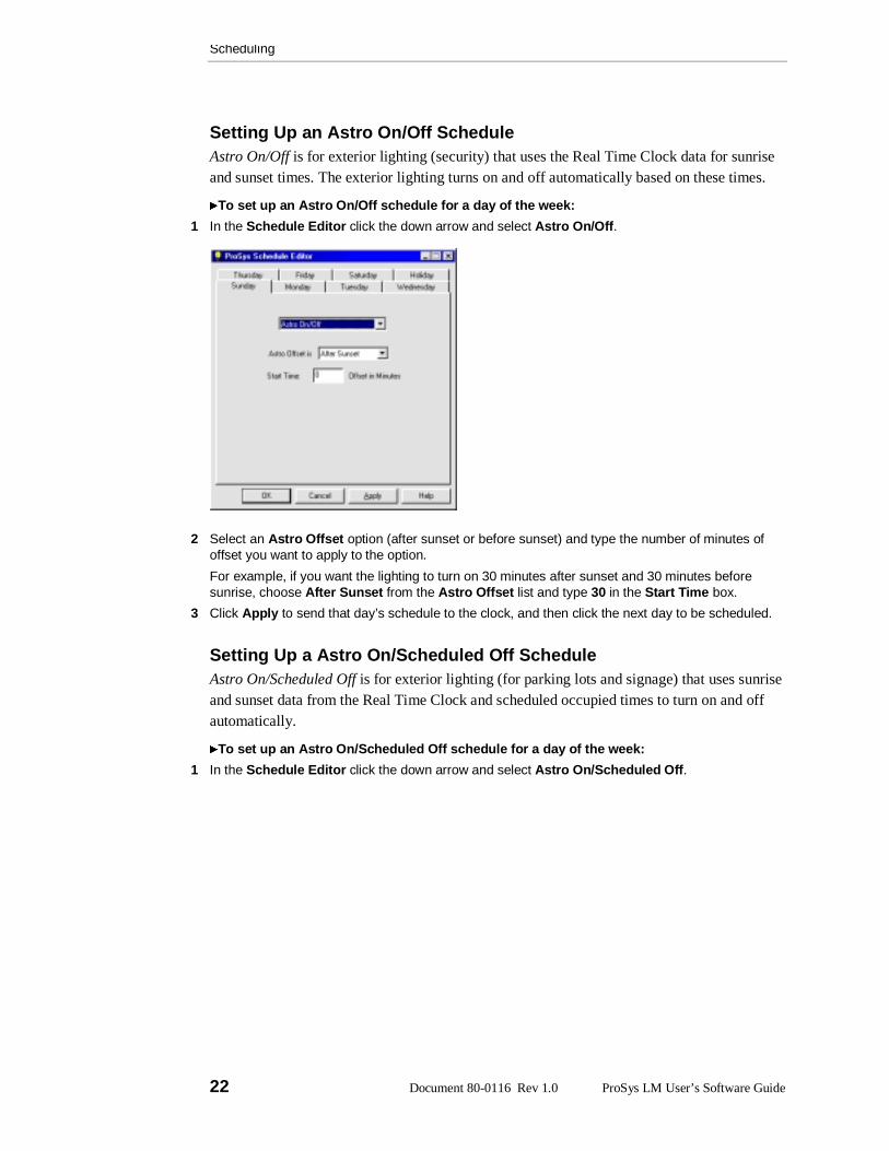
Setting Up an Astro On/Off ScheduleAstro On/Off is for exterior lighting (security) that uses the Real Time Clock data for sunriseand sunset times. The exterior lighting turns on and off automatically based on these times.
To set up an Astro On/Off schedule for a day of the week:
1 In the Schedule Editor click the down arrow and select Astro On/Off.
2 Select an Astro Offset option (after sunset or before sunset) and type the number of minutes ofoffset you want to apply to the option.
For example, if you want the lighting to turn on 30 minutes after sunset and 30 minutes beforesunrise, choose After Sunset from the Astro Offset list and type 30 in the Start Time box.
3 Click Apply to send that day’s schedule to the clock, and then click the next day to be scheduled.
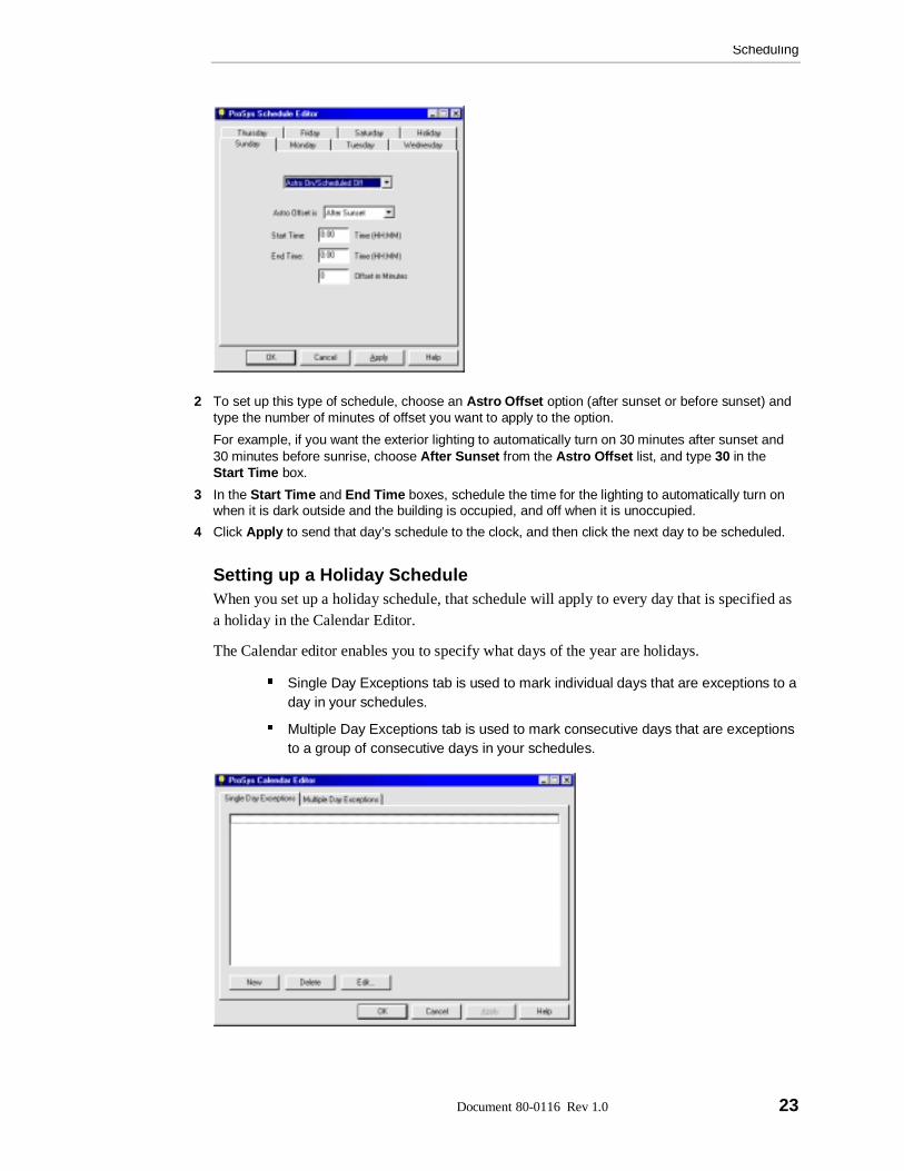
Setting Up a Astro On/Scheduled Off ScheduleAstro On/Scheduled Off is for exterior lighting (for parking lots and signage) that uses sunriseand sunset data from the Real Time Clock and scheduled occupied times to turn on and offautomatically.
To set up an Astro On/Scheduled Off schedule for a day of the week:
1 In the Schedule Editor click the down arrow and select Astro On/Scheduled Off.
Scheduling
Document 80-0116 Rev 1.0 23
2 To set up this type of schedule, choose an Astro Offset option (after sunset or before sunset) andtype the number of minutes of offset you want to apply to the option.
For example, if you want the exterior lighting to automatically turn on 30 minutes after sunset and30 minutes before sunrise, choose After Sunset from the Astro Offset list, and type 30 in theStart Time box.
3 In the Start Time and End Time boxes, schedule the time for the lighting to automatically turn onwhen it is dark outside and the building is occupied, and off when it is unoccupied.
4 Click Apply to send that day’s schedule to the clock, and then click the next day to be scheduled.
Setting up a Holiday ScheduleWhen you set up a holiday schedule, that schedule will apply to every day that is specified asa holiday in the Calendar Editor.
The Calendar editor enables you to specify what days of the year are holidays.
� Single Day Exceptions tab is used to mark individual days that are exceptions to aday in your schedules.
� Multiple Day Exceptions tab is used to mark consecutive days that are exceptionsto a group of consecutive days in your schedules.
Scheduling
24 Document 80-0116 Rev 1.0 ProSys LM User’s Software Guide
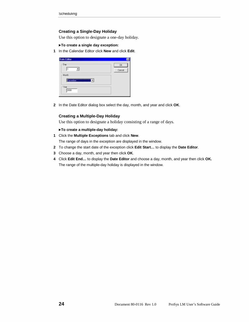
Creating a Single-Day HolidayUse this option to designate a one-day holiday.
To create a single day exception:
1 In the Calendar Editor click New and click Edit.
2 In the Date Editor dialog box select the day, month, and year and click OK.
Creating a Multiple-Day HolidayUse this option to designate a holiday consisting of a range of days.
To create a multiple-day holiday:
1 Click the Multiple Exceptions tab and click New.
The range of days in the exception are displayed in the window.
2 To change the start date of the exception click Edit Start… to display the Date Editor.
3 Choose a day, month, and year then click OK.
4 Click Edit End… to display the Date Editor and choose a day, month, and year then click OK.
The range of the multiple-day holiday is displayed in the window.
ProSys LM User’s Software Guide Document 80-0116 Rev 1.0 25
Chapter 5
Configuring Softwired Switches
Softwiring A Switch’s ButtonsThe Softwired Switch can be configured so that each button can control:
� Any channel on any panel
� Any relay or group of relays on a single panel to a pattern
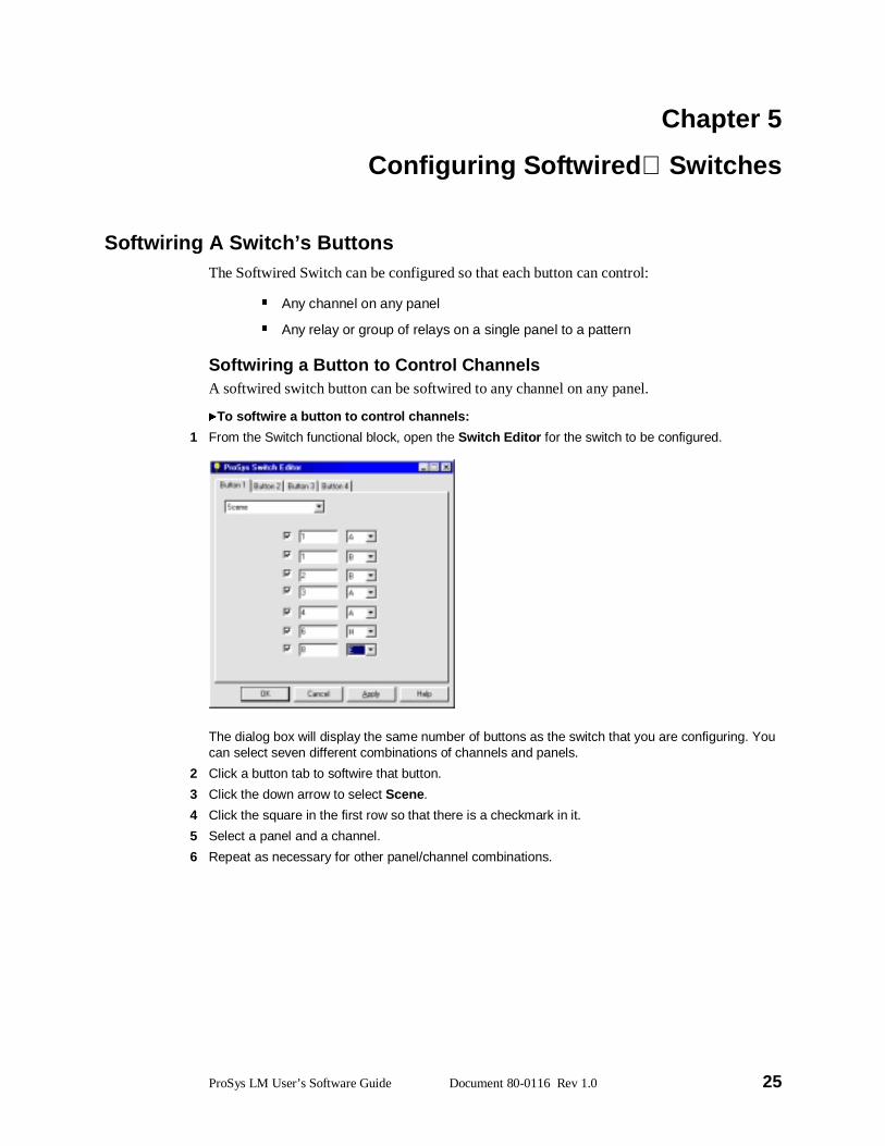
Softwiring a Button to Control ChannelsA softwired switch button can be softwired to any channel on any panel.
To softwire a button to control channels:
1 From the Switch functional block, open the Switch Editor for the switch to be configured.
The dialog box will display the same number of buttons as the switch that you are configuring. Youcan select seven different combinations of channels and panels.
2 Click a button tab to softwire that button.
3 Click the down arrow to select Scene.
4 Click the square in the first row so that there is a checkmark in it.
5 Select a panel and a channel.
6 Repeat as necessary for other panel/channel combinations.
Configuring Softwired Switches
26 Document 80-0116 Rev 1.0 ProSys LM User’s Software Guide
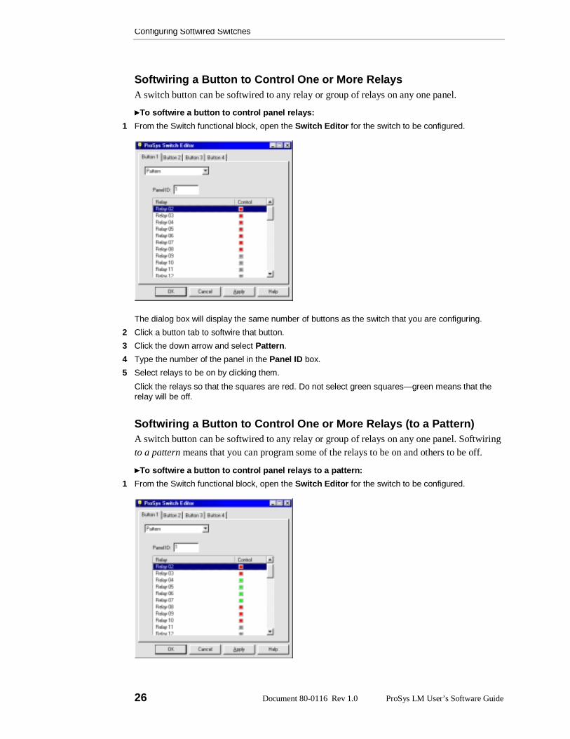
Softwiring a Button to Control One or More RelaysA switch button can be softwired to any relay or group of relays on any one panel.
To softwire a button to control panel relays:
1 From the Switch functional block, open the Switch Editor for the switch to be configured.
The dialog box will display the same number of buttons as the switch that you are configuring.
2 Click a button tab to softwire that button.
3 Click the down arrow and select Pattern.
4 Type the number of the panel in the Panel ID box.
5 Select relays to be on by clicking them.
Click the relays so that the squares are red. Do not select green squares—green means that therelay will be off.
Softwiring a Button to Control One or More Relays (to a Pattern)A switch button can be softwired to any relay or group of relays on any one panel. Softwiringto a pattern means that you can program some of the relays to be on and others to be off.
To softwire a button to control panel relays to a pattern:
1 From the Switch functional block, open the Switch Editor for the switch to be configured.

Configuring Softwired Switches
Document 80-0116 Rev 1.0 27
The dialog box will display the same number of buttons as the switch that you are configuring.
2 Click a button tab to softwire that button.
3 Click the down arrow and select Pattern.
4 Type the number of the panel in the Panel ID box.
5 Select relays by clicking them.
A red square indicates that the relay will be on; a green square indicates that the relay will be off; agray square indicates that the relay is not a part of the pattern group

ProSys LM User’s Software Guide Document 80-0116 Rev 1.0 29
Chapter 6
Monitoring a Lighting Network
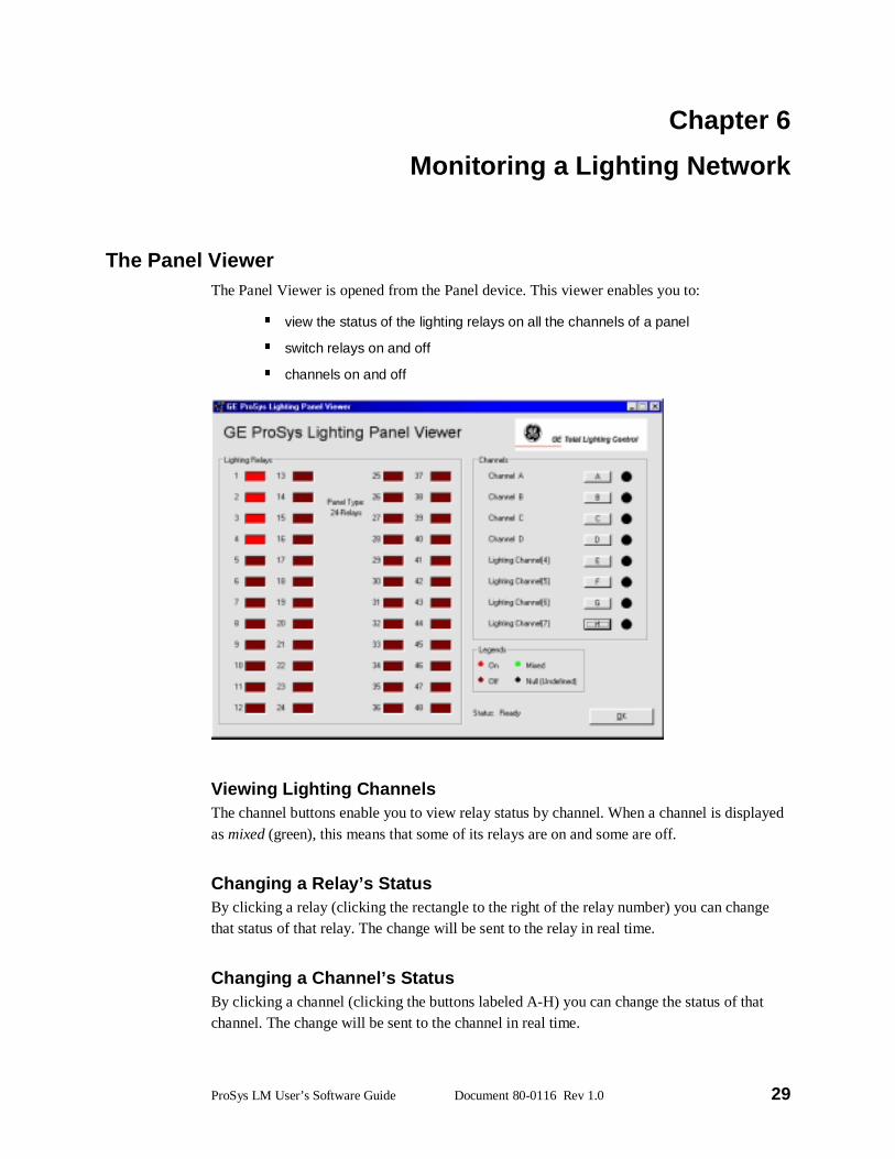
The Panel ViewerThe Panel Viewer is opened from the Panel device. This viewer enables you to:
� view the status of the lighting relays on all the channels of a panel
� switch relays on and off
� channels on and off
Viewing Lighting ChannelsThe channel buttons enable you to view relay status by channel. When a channel is displayedas mixed (green), this means that some of its relays are on and some are off.
Changing a Relay’s StatusBy clicking a relay (clicking the rectangle to the right of the relay number) you can changethat status of that relay. The change will be sent to the relay in real time.
Changing a Channel’s StatusBy clicking a channel (clicking the buttons labeled A-H) you can change the status of thatchannel. The change will be sent to the channel in real time.
Monitoring a Lighting Network
30 Document 80-0116 Rev 1.0 ProSys LM User’s Software Guide
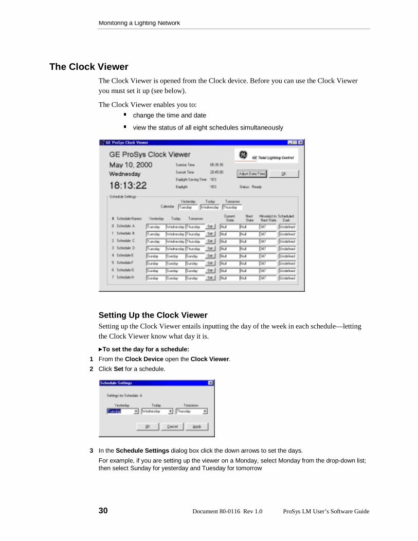
The Clock ViewerThe Clock Viewer is opened from the Clock device. Before you can use the Clock Vieweryou must set it up (see below).
The Clock Viewer enables you to:
� change the time and date
� view the status of all eight schedules simultaneously
Setting Up the Clock ViewerSetting up the Clock Viewer entails inputting the day of the week in each schedule—lettingthe Clock Viewer know what day it is.
To set the day for a schedule:
1 From the Clock Device open the Clock Viewer.
2 Click Set for a schedule.
3 In the Schedule Settings dialog box click the down arrows to set the days.
For example, if you are setting up the viewer on a Monday, select Monday from the drop-down list;then select Sunday for yesterday and Tuesday for tomorrow
ProSys LM User’s Software Guide Document 80-0116 Rev 1.0 31
Index
C
Clock. See schedulingcomputer system requirements, 3
D
devicesoverview, 5
F
Flick Warn, 15assigning to relays, 15
functional blocksoverview, 5
I
installing plug-ins, 7
L
lighting panels, 13softwiring a relay pattern to a channel,
14softwiring a relay to a channel, 13
M
message tag binding, 9
N
network variable binding, 8
P
plug-insinstalling, 7overview, 5
R
Real Time Clock. See scheduling
RR9 Relaysselecting, 16
S
schedulesAstro On/Off, 22Astro On/Scheduled Off, 22daily schedules, 20Holiday, 23Manual On/Off, 21On/Off, 21
scheduling, 17daylight savings time, 19Network Time Update, 20setting the time, 17time zone and location, 18
self-install mode, 10putting devices into, 10
software-install mode, 10Softwired Switch. See SwitchSwitch
softwiring a button to control channels,25
softwiring a button to control one ormore relays, 26
softwiring a button to control one ormore relays (to a Pattern), 26
T
Time Delay, 14
V
Viewer, Clock, 30setting up, 30
Viewer, Panel, 29changing a relay’s status, 29viewing lighting channels, 29

DEH40109 Installation Instructions
GE Total Lighting Control
GE Total Lighting Control41 Woodford Avenue, Plainville, CT 06062
©2000 General Electric Company
DEH40109 BL 0700 R01