prospects and problems of optical diffuse wireless communication
TRANSCRIPT

Prospects and Problems of Optical Diffuse Wireless Communication for Underwater Wireless Sensor Networks (UWSNs) 1
Prospects and Problems of Optical Diffuse Wireless Communication for Underwater Wireless Sensor Networks (UWSNs)
Davide Anguita, Davide Brizzolara and Giancarlo Parodi
0
Prospects and Problems of OpticalDiffuse Wireless Communication for Underwater
Wireless Sensor Networks (UWSNs)
Davide Anguita, Davide Brizzolara, Giancarlo ParodiUniversity of Genoa
Italy
1. Introduction
The aim of this paper is to highlight the prospects and problems of optical wireless com-munication for applications in the field of Underwater Wireless Sensor Networks (UWSNs).The necessity of wireless underwater connections, especially in UWSN, has dramatically in-creased in the last few years for a wide range of applications, from environmental monitoringto surveillance. The problem of wireless underwater communication is a challenging fieldof investigation since common terrestrial devices, equipped with radio wireless links, cannotbe employed underwater and current underwater available technologies, mainly based onacoustical solutions, still pose problems due to low propagation speed of sound in water andlow data-rate.In the last years, the interest towards optical wireless communication has increased both forterrestrial (Akella et al., 2005) than for underwater applications (Doniec et al., 2010) sinceit allows to overcome some of the problems of acoustical communication (Akyildiz et al.,2005). In fact low data rate and low propagation speed require specific solutions and make itdifficult the integration of underwater technologies with current available terrestrial modules.Transferring the paradigm of Smart Dust (V. Hsu & Pister, 1998) to UWSNs, largely unaffectedby WSN revolution, is a challenge that can open great opportunities since current underwatersolutions are still of large dimension, expensive and power-consuming.
Fig. 1. Wireless Node Structure equipped with FPGA
1
www.intechopen.com

This paper highlight the relatively less explored and innovative possibility of optical under-water communication as an interesting and feasible alternative solution for underwater net-working targeting small, low-cost and low-power devices. In particular it focuses both theproblems related to specific characteristics of the underwater channel targeting the interfacewith current terrestrial technologies available for Wireless Sensor Network (WSN) such as theone developed at DIBE WiseLab (Akyildiz et al., 2005) depicted in Fig.1 .The goal of our work is to build a prototype of an UWSN based on optical communicationamong nodes. The optical PHY and MAC Layers have been developed considering the char-acteristics of IEEE 802.11 Infrared (IR) PHY layer and the compatibility with the current IEEE802.15.4 protocol for terrestrial Wireless Sensor Networks (WSNs). This can be considered asa first step which, of course, should be followed by modifications and adaptation of the upperlayers.The network architecture can be organized as a three or bi-dimensional underwater net-work in which each node floats at different depths trying to maintain a fixed position witha good approximation, for instance by an anchorage to the sea bed (as detailed in Chapter11). The nodes should be designed of slight dimensions (between 15 and 20 cm), they shouldbe densely deployed, maintaining a distance between 10 and 30 meters from each other. Asdetailed in the next paragraph, each node should be able to communicate, by using only awireless optical communication link, to the neighbors and, by using a multi hop path, to abase station placed on the water surface.The interesting aspects which are reported in this work are related to:
• the use of optical communication (the adaptation of current available protocols, thechoice of modulation, the adaptation to water channel variability, etc ...);
• the interface with current technology for WSN;
• the design and implementation of circuits for diffuse generation and reception of lightimpulses targeting low-cost and low-power components;
Fig. 2. Underwater Attenuation of Light from experimental data
www.intechopen.com

Prospects and Problems of Optical Diffuse Wireless Communication for Underwater Wireless Sensor Networks (UWSNs) 3
Acoustic Electromagnetic Optical
Nominal speed (m/s) ≈ 1, 500 ≈ light − speed ≈ light − speed
Power Loss 0.1dB/m/Hz ≈ 28dB/1km/100MHz ∼ turbidity
Bandwidth ≈ kHz ≈ MHz 10 − 150MHz
Frequency band ≈ KHz ≈ MHz 1014− 1015Hz
Antenna size ≈ 0.1m ≈ 0.5m ≈ 0.1m
Effective range ≈ km ≈ 10m ≈ 10 − 100m
Table 1. Comparison of Different Technologies for Underwater Wireless Communication
2. Underwater Wireless Communication: physical aspects
Due to the impossibility of using Radio Frequencies (RF), traditionally wireless underwatercommunication employs acoustic waves because sound propagates well in water and its rangecan be very long (∼km). However, it has several disadvantages such as narrow bandwidthand latency in communication due to the slow speed of acoustic wave in water. For instance,at ranges of less than 100 m the data transmission rates of these systems in shallow littoralwaters are ∼10 kb/s.Experimental tests have shown that an alternative feasible solution is optical communica-tion especially in blue/green light wavelengths, even if limited to short distances (up to 100m)(Lanbo et al., 2008). Compared to acoustic communication it offers a practical choice forhigh-bandwidth communication and it propagates faster in the water (2.255 x 10⁸).Nevertheless it is affected by different factors to take into account for an efficient design. Theattenuation of a light beam between two points can be described as in 1 where d1 and d2 arethe positions of the points.
A = e−k(d1−d2)(
d1
d2
)2
(1)
In the first term, k is defined as k = a(λ) + b(λ) and it is dependent by the wavelength: ais the term related to the absorption of water while b models the scattering which dependsboth on light wavelength and turbidity. The second term, instead, models the quadratic at-tenuation. A comparison between different wireless underwater technologies for underwatercommunication is illustrated in Table 1.
3. Wireless Underwater Communication Systems: analysis of the state of art
In this chapter will be briefly investigated the state of art related to underwater wireless com-munication.Currently the use of wireless communication is very common in a wide range of terrestrialdevices. In particular, one of the most innovative application is related to Wireless Sensor Net-works (WSNs), as well detailed in (Akyldiz et al., 2001) (Puccinelli & Haenggi, 2005), where alarge number of small nodes communicate and work by using an optical wireless link.
3.1 Underwater Acoustical Communication
As discussed in the introduction, although there are many recently developed solutions forWSNs, the unique characteristics of the underwater acoustic communication channel, suchas limited bandwidth capacity and variable delays, require very efficient and reliable newdata communication protocols and UWSNs nodes are still an open field of research (Akyldiz
www.intechopen.com

et al., 2001) (Akyildiz et al., 2005) (Lanbo et al., 2008). The main limitations due to acousticcommunication, which will be described can be summarized as follows:
• The available bandwidth is severely limited;
• The underwater channel is severely impaired, especially due to multi-path and fading;
• Propagation delay in underwater is five orders of magnitude higher than in radio fre-quency (RF) terrestrial channels, and extremely variable;
• High bit error rates and temporary losses of connectivity (shadow zones) can be expe-rienced, due to the extreme characteristics of the underwater channel.
Considering low-power and low-cost devices and targeting short-medium distances, the mostimportant available products are described in (Yan et al., 2007) (Singh et al., 2006) and theycan reach data-rate in the order of Kb/s.
3.2 Underwater Electromagnetic Communication
As regards Electromagnetic Communication, extremely low frequency radio signals havebeen used in military applications: Germans pioneered electromagnetic communication inradio frequency for submarines during World War II, where the antenna was capable of out-putting up to 1 to 2 Mega-Watt (MW) of power. An extremely low frequency (ELF) signal,typically around 80 Hz at much lower power, has been used to communicate with naval sub-marines globally today. This is possible mainly because most of the transmission paths arethrough the atmosphere (Shelley, 2005).In (Al-Shamma’a et al., 2004) a theoretical analysis and experiments show that radio waveswithin a frequency range 1 to 20MHz is able to propagate over distances up to 100 m by usingdipole radiation with transmission powers in the order of 100 W. This will yield high datarates beyond 1 Mbps which allows video images to be propagated at standard camera framerates (25Hz) (Lucas et al., 2004). The antenna design in such case is very different from thatof the antennas used for conventional service in the atmosphere: in fact, instead of havingdirect contact with seawater, the metal transmitting and receiving aerials are surrounded bywaterproof electrically insulating materials. This way, an EM signal can be launched from thetransmitter into a body of seawater and picked up by a distant receiver.Recently, in September 2006, the first commercial underwater radio-frequency (RF) modem inthe world, model S1510, was released by Wireless Fibre Systems (Fibre, 2008). Its data rate is100 bps, and communication range is about several tens of meters. In January 2007, a broad-band underwater RF modem, model S5510, came into birth. It supports 1-10 Mbps within 1meter range (Fibre, 2008). Due to the propagation property of EM waves, EMCOMM is anappealing choice only for very short range applications. One example is the communicationbetween autonomous underwater vehicles (AUVs) and base stations, where the AUVs canmove within the communication range of a base station to offload data and receive furtherinstructions (Shelley, 2005).
3.3 Optical Underwater Wireless Communication
Underwater optical communication has been investigated both through theoretical studies(Jaruwatanadilok, 2008) (Lanbo et al., 2008) (Kedar, 2007) and in experimental tests (Feng Lu,2009)(Hanson & Radic, 2008), mainly developed in USA, Canada and Australia.Currently, there are not many research activities on underwater optical communication, andfew commercial optical modems are available specifically for underwater communication.As well detailed in the next paragraphs, recent interests in underwater sensor networks and
www.intechopen.com

Prospects and Problems of Optical Diffuse Wireless Communication for Underwater Wireless Sensor Networks (UWSNs) 5
sea floor observatories have greatly stimulated the interest in short-range high-rate opticalunderwater communication.
3.3.1 Point-to-point Communication
In (Tivey et al., 2004) a low power and low cost underwater optical communication system isproposed by using inespensive components. It is based on IrDa protocol and the adaptation tounderwater channel is performed by replacing Infrared Communication with light generatedby LEDs. Also in (Shill et al., 2004) an underwater communication system has been imple-mented for a swarm of submersibles. It combines the IrDA physical layer with 3 Watt highpower light emitting diodes, emitting light in the green and blue part of the visible spectrum.As in the previous example, the approach is to use the IrDA physical layer modulation replac-ing the infrared light emitting diodes (LEDs) with high power green or blue LEDs, and alsothe photodiode with a type which is sensitive in the visible part of the spectrum. The pro-totype transceiver costs approximately $45 per unit and, on this low hardware level, no linkmanagement or higher level error correction is done. The wide angular coverage, the uniformemission footprint and very high light intensity allow for either omnidirectional coverage upto 2 metre radius with only five transmitters, when using simultaneously transmitting expen-sive LEDs that consume 2W or, with additional lenses, long range directional links having acollimated beam (up to 5 meters).In (Feng Lu, 2009) and (Lee et al., 2008) a low-cost (in the order of $10)medium-range opticalunderwater modem is proposed. A sophisticated detection algorithm is exploited (based onspread spectrum) to maximize the communication range. Tests have been performed up to 10meters and a data-rate of 310bps has been achieved.In (Vasilescu et al., 2007) and (Vasilescu et al., 2005) the underwater wireless sensor networkAquaNodes is described. In this application the use of optical communication is shown as anefficient solution for data muling in the network proposed by CSIRO ICT Centre (Australia)and MIT CSIAL (USA). This research proposes a network where data exchange is performedby connecting, both optically and acoustically, previously deployed static nodes and mobile(AUVs) vehicles, so that the characteristics of the two communication strategies can be ex-ploited. Each device is provided with an optical modem, which can perform a transmission upto 300 kb/s in a range below 8 meters. This approach clearly shows that the use of an opticalcommunication system allows for a considerable reduction in terms of energy consumptionwith respect to a multi-hop acoustic transmission and a resulting increase of operational lifeof the system. Moreover, considering this work, the use of optical modems instead of acousticones for short range communications leads to a remarkable reduction of costs, since the cost ofan optical modem is of the order of $50 node against approximately $3000 node of an acousticmodem.In (Ito et al., 2008a) is illustrated a careful analysis by modeling the underwater channel basedon underwater optics. Through this analysis, it is showed that a single color LED is veryweak in a wavelength dependent underwater channel and, to overcome this problem, a multi-wavelength adaptive scheme combined with rate adaptive transmission is proposed takinginspiration from already developed algorithms. The proposed system can adapt to the chan-nel by considering the change in power for each wavelength band, and controlling the datarate.In (Hanson & Radic, 2008) the work is motivated by the need to demonstrate error-free under-water communication at qualitatively higher data rates than previously reported with eitheroptical or acoustic methods. In this case a Laser source is used and an error-free underwater
www.intechopen.com

optical transmission measurements at 1 Gbit/s over a 2 m path in a laboratory water pipe.In (Chancey, 2007) a short range underwater optical communication link is established byusing an open source free space modem proposed by the project RONJA. Unfortunately, theused equipment is very expensive and difficult to use in real applications; as reported, theexperimental results achieved 10 Mb/s at a distance up to 5 meters.A commercial product targeting optical underwater communication, from Ambalux (Am-balux, 2008), includes high-bandwidth transceivers, which allow a point-to-point transmis-sion at a data rate of 10Mbs up to 40m, depending on environmental conditions. A set oftests based on this commercial products has been described in (Baiden & Bissiri, 2007), wherea solution for omni-directional communication is also proposed in order to improve the effi-cacy of the connection with an underwater untethered vehicle. This approach, however, is notsuitable for a dense UWSN or small and low power devices, where nodes are deployed withlow accuracy and concerns on system size and energy consumption are addressed.Recently an underwater optical wireless modem (AquaOptical)(Doniec et al., 2009) has beenimplemented. It is designed for integration in robotic application and allows to support awireless communication of 2 Mb/s up to a range of 30m.
3.4 Diffusive underwater optical communication
In these paragraph are reported some researches related to the use of diffusive underwateroptical communication for different applications.In (Baiden et al., 2009) the point-to-point optical communication system developed by Am-balux (Ambalux, 2008) is used to perform a wide number of tests with the aim of paving theway for a future underwater omni-directional wireless optical communication systems. TheLEDs used in the test emitted light in the green and blue light spectrum and were tested ina pool and in a tank filled with lake water. The primary objective of these tests was to getprofiles of the behaviors of such communication systems with respect to water characteristicssuch as turbidity levels, prior to building an omni-directional optical communication. Theresults of the tests indicated that turbidity level, viewing angle and separation distance playsa significant role in the behavior of blue light in water. In particular, the aim was to define athreshold viewing angle (TVA), the minimum viewing angle at which communication is lostwhen one of the communication devices is rotated with respect to a virtual axis that containsthe segment represented by the center of gravities of the two devices when they are aligned.On the basis of the previous studies, two geometric forms were modelled: icosahedron andspherical hexagon. The icosahedron was retained because of its simplicity in geometry and itsability to provide complete free space coverage using the selected LED.In (Baiden & Bissiri, 2007), the previous illustrated configuration has been tested to imple-ment a high bandwidth optical networking for underwater untethered tele-robotic operation.A rate of 4 Mb/s was achieved in hemispherical configuration up to 5 meters. Experimenta-tion in the field achieved initially 115 Kb/s over a distance of 15 metres. A second experiment,after the modification of the transmitter and the receiver software, was attempted: in this casethe transmission was increased to 1.5 Mb/s and the first wireless underwater video pictureswere transmitted. Despite the originally anticipated different kinds of turbidity (fish, plank-ton, rocks or other objects) in the water, the experiment still received video feedback of theanchor of a floating laboratory at around 15 metres deep in the bottom of the lake.In (Fair et al., 2006) an optical modem technology for seafloor observatories is illustrated andproblems related to design and implementation of a system for underwater optical wirelesscommunication are focused. The idea is to implement an optical modem system which should
www.intechopen.com

Prospects and Problems of Optical Diffuse Wireless Communication for Underwater Wireless Sensor Networks (UWSNs) 7
provide sufficient bandwidth to allow transmission of compressed high resolution video (i.e.,2-10 Mbit/s for studio quality video), allowing nearly unrestricted motion on the part of themobile sensor (UUV), and working at ranges below 100 m. In this case, the design of the sys-tem have been developed considering the following aspects: (1) selection of a transmissionlight source (wavelength, power, beamwidth), (2) selection of a detector (field of view, quan-tum efficiency, gain), and (3) selection of an aiming and tracking strategy. As regards trans-mission light source, LEDs are suggested to be used for the transmitters as they are switchableat high rates, can be reasonably collimated, and are easily arrayed to increase transmit power.High intensity blue LEDs such as those fabricated from Gallium Indium Nitride (InGaN) ona silicon carbide (SiC) substrate can provide on the order of 10 mW each and they can beconfigured in arrays to increase the total radiant flux (optical power). The light from one ormore LEDs can be collimated with a lens to focus its beam. While their bandwidth is low byoptical standards (30 ns rise time), a 100 ns bit duration meets the design goal of 10 Mbit/s.LED transmitters provide significant flexibility as well: both OOK and PPM are possible withthe same hardware. As regards the receiver, in this work a photomultiplier tube (PMT) ischosen for the detector because it provides higher sensitivity and less noise than photodiodes(including avalanche or PIN types) although the tube size can be a limiting factor in certainconditions. Considering the aiming and tracking strategies, three possible configurations foroptical communications between a fixed node and a free-swimming vehicle are suggested inthis paper:
1. Pointed transmission (Tx) and reception (Rx) with acoustic or optical aiming is the mostefficient scenario from an optical transmission standpoint. The transmitter consists ofseveral collimated LEDs or a laser diode, and the receiver is a PMT. This method re-quires a search and acquisition mode by both the Rx and Tx which consumes time andenergy (regardless of whether the aiming is acoustic or optical);
2. Directional-Tx to omni-directional-Rx scenario can be accomplished with a hemispher-ical PMT detector and either a laser diode or a hemispherical array of LEDs. In thiscase, the aiming problem is one-sided and could be accomplished via acoustics or withoptics;
3. Omni-directional Tx and Rx which is the mechanically simplest solution. This can be ac-complished using the large area PMT detector with a moderate output-power blue laserdiode or LED and diffusing optics. The diffusing optics can be done either with discretereflective and refractive elements or with a high transmission scattering medium.
Taking into account the previous proposed theoretical studies, some optical systems havebeen implemented and tested, as reported in (Farr et al., 2005). The omni-directional lightsource used was blue-green (470nm) to take advantage of the low attenuation in seawater atthose wavelengths, and produced a uniform light field over a 2π steradian hemisphere. Sixcommercially available 470nm (blue) light emitting diodes (LED) were arranged in a hemi-spherical geometry and encapsulated in a weekly scattering potting material to provide somediffusion of the light field over the full hemisphere of operation. The receiver consisted of alarge-aperture, hemispherical photomultiplier tube (PMT) chosen for its high sensitivity, lownoise and high speed. Apertures and mirrors have been used to obtain a 91 m path length ina 15 m deep pool and to prevent reflections from the surrounding walls from contaminatingthe results. A 100 meter bench test has been performed to verify the range and geometry cal-culation using neutral density filters to simulate the attenuation of water.In the same work (Farr et al., 2005) different tests are performed to validate the concept of
www.intechopen.com

omni-directional free water optical communication in the range of 10 meters. In particular,the power spectrum of the received signal during the transmission of a pulse train at differentrepetition rates is reported: 1.25 MHz, 5 MHz and 10 MHz.This work focuses in particular the communication between Underwater Mobile Vehicles anda fixed node targeting application in sea oor observatories. The achieved distances and data-rate are interesting but it could be difficult to apply these results to low-cost and small deviceswhere transmitters and receivers should be placed on the same small surface.In (Liu & Ge, 2006) the concept of underwater laser sensor network is illustrated as a newapproach for broadband communication in the underwater environment based on the blue-green laser has been proposed. In this paper the applications of the underwater sensor net-work in the undersea exploration are discussed with the difficulties in the traditional the un-derwater acoustic sensor network. A basic of prototype of underwater laser sensor network isdescribed: it includes the architecture of laser sensor node and protocol stack for underwaterlaser sensor network, but it does not shown implementation or interesting practical results.The here described devices show that the use of optical communication can be a feasible so-lutions for underwater wireless communication. In the comparison with the here proposedworks, the aim of this paper is to illustrate the problems and possible solutions for the ap-plication of optical wireless communication in order to support a UWSN of dense deployednodes as detailed in Chapter 1 and 11.
4. Application of underwater optical wireless communication
Optical underwater communication is an effective alternative to current underwater technol-ogy especially in some particular environments such as, for instance, shallow, coastal andfresh inland waters where the use of this approach is useful to overcome all the shortcomingsrelated to the use of acoustic communication and to allow a wide adoption of underwatermonitoring systems. In particular the possibility of transferring high amount of data in a lim-ited amount of time reducing power consumption can support the transmission of short videoand pictures for a reliable monitoring and surveillance. Small dimensions and low-cost com-ponents allow to establish a dense deployed networks performing an effective fine grainedsampling in the area of interest. It could be possible, for instance, to perform pollution mon-itoring and frequent data collection (water temperature, specific conductivity, pH, turbidity,and possibly oxygen concentration) and, by using a high-data rate optical link, periodicallydeliver data reducing the time devoted to transmission and network congestion.
5. Design consideration for a diffuse optical underwater communication
The design of underwater optical systems for underwater networking should takes into ac-count different aspects which are illustrated in the next paragraphs:
• the Physical(PHY) Layer to manage the trasmission and reception of data by using de-voted circuits;
• the Medium Access Control(MAC) Layer to manage the possibility of more than onedevices to communicate each others;
• the aspects related to the circuits design and implementation (such as choice of the Ledand photodiodes and their collocation on a surface).
www.intechopen.com

Prospects and Problems of Optical Diffuse Wireless Communication for Underwater Wireless Sensor Networks (UWSNs) 9
In the next paragraph some design consideration for each of the previous aspect will be pre-sented and our design and implementation results will be briefly illustrated. The here de-scribed system is an based on a previous implementation illustrated in (Anguita et al., 2010)(Anguita et al., 2008) (Anguita et al., 2009) and it implements PHY and MAC Layer moduleswhich have been described by using an Hardware Description Language (HDL), in particularVHDL (Very High Speed Hardware Description Language), as suggested in (Pang et al., 2007)(Dasalukunte & Owall, 2008) and well detailed in Chapter 6.3.
Fig. 3. General block diagram of the Optical Transmission System
6. The Physical Layer
The Physical Layer has to support:
1. the transmission and reception of data by using optical communication;
2. the interface with a MAC Layer of the communication stack by providind the servicesrequired by the upper layers.
In particular, the design should take into account the peculiarity of underwater channel andfocus on the following elements:
1. efficient wireless optical modulation techniques;
2. adaptation to underwater channel variability;
3. adaptation to data-rate communication requirements;
4. interface with current standard used for WSN (i.e. IEEE 802.15.4).
www.intechopen.com

Modulation ImplementationComplexity
Sensitivity to multi-path delay
Requiredtransmittedpower
Bandwidth
OOK simple general PR−OOK 2RB
FSK most complex most anti-sensitive 12 PR−OOK | f1 − f0| + 2RB (2
FSK)
DPSK more complex more sensitive 18√
ln 2PR−OOK 2RB (2 DPSK)
PPM simple general 2PR−OOK
Llog2 L RB (L-PPM)
Table 2. Comparison of Various Modulations Techniques
6.1 Wireless optical modulation techniques
As well detailed in literature (Ghassemlooy et al., 2007) (Park & Barry, 1995) (Kahn & Barry,1997) basic modulation techniques mainly contain three formats, such as Amplitude Modula-tion (ASK), Frequency Modulation (FSK) and Phase Modulation (PSK).Taking into account previous reported studies (Lee et al., 2008), Pulse-Position Modulation(PPM) can be considered in order to further improve the anti-disturbance capacity of infor-mation transmission and it proposed in different systems both for terrestrial (IEEE 802.11 IR)than for underwater systems (Lee et al., 2008).Pulse Position modulation is a well-known orthogonal modulation technique, in which Mmessage bits are encoded by transmitting a single pulse in one of 2M possible time-shift. PPMscheme, at each time interval is Ts and L = 2M time-shifts constitute a PPM frame. At thetransmitter end, the signal will be launched by the light pulse to form a specific time slot,and in the receiver end, the photoelectric diode detects the light pulse and then to judge itstime slot to evaluate his position and resume the signal. In L-PPM system, a block of inputbits is mapped on to one of distinct waveforms, each including one ”on” chip and M-1 ”o f f ”chips. A pulse is transmitted during the ”on” chip, it can be defined as (Meihong, Xinsheng &Zhangguo, 2009):
Pm =
{
is t ∈ [m − 1]Tf /L, mTf /L
0 else(2)
Considering the characteristics of the different modulation the Table 2 can be proposed for acomparison between different techniques (RB is the base-band signal bandwidth).Since the characteristics of PPM appeared to be interesting for a wide range of applicationssome alternative and modified PPM modulations can be considered such as Differential PulsePosition Modulation (DPPM), Pulse Interval Modulation (PIM) and Dual Header Pulse Inter-val Modulation (DH-PIM).
6.1.1 BER vs. SNR
Considering the previous described modulations it is interesting to evaluate the Bit Error Rateversus SNR. The following results are mainly based on (Meihong, Xinsheng & Zhangguo,2009) (Meihong, Xinsheng & Fengli, 2009). For OOK demodulation format a threshold is usedto compare the received voltage to decide "1" or "0". In AWGN channel model, the receivedvoltage is:
www.intechopen.com

Prospects and Problems of Optical Diffuse Wireless Communication for Underwater Wireless Sensor Networks (UWSNs) 11
p(t) =
{
is + nc(t), "1"
nc(t), 0"(3)
where nc(t) is the Gaussian process. For the data "1", the probability density of x(t) is:
p1(x) =1
√
2πσ
exp(−(x − is)2
2σ2
) (4)
for the data bit "0" the probability density of x(t) is:
p0(x) =1
√
2πσ
exp(−x2
2σ2) (5)
By fixing the the judgment threshold to 12 i, the bit error rate is defined as:
pe(ook) =1
2er f c
is
2√
2σ
=1
2er f c
√
S
2√
2(6)
where erfc is the complementary error function. According to (Lee & Kahn, 1999), in additiveGaussian noise channel, the bit error rate of 2FSK coherent modulation and 2DPSK coherentmodulation are given by the following equations:
pe(FSK) =1
2er f c
√
S
4(7)
pe(DFSK) = er f c
√
S
2(1 −
1
2
S
2) (8)
For the L-PPM modulation in the Gaussian white noise channel, there are many performanceevaluation methods for the BER as suggested in (C.X.Fan et al., 2001) (Ma, 2003) (Malik et al.,1996). The following formula is used in (Meihong, Xinsheng & Fengli, 2009):
pe(L − PPM) =1
L[1
2er f c(
1 − k
2√
2√
LS) +
L − 1
2er f c(
k
2√
2
√
LS)] (9)
in order to show the Bit Error Rate in different SNR conditions. The 8-PPM is reported to be agood choice to reduce the BER.
6.1.2 Power Consumption
Also problems related to power consumption has been investigated in literature (Tivey et al.,2004) (Meihong, Xinsheng & Zhangguo, 2009) since they are crucial in underwater devices.Small and light systems are desirable in order to improve underwater system performanceand considerations about power consumption are important in the choice of modulation. Thefollowing considerations can be carried out for the different modulations:
1. for the Frequency Shift Key (FSK) modulation a specific frequency carrier wave fordigital ”1”, and a different frequency carrier wave for digital ”0” are generated. Inthis case the optical transmit power required as the transmitting duration is always onand it appears to be inefficient for applications on power-constrained devices.
www.intechopen.com
OOK FSK DPSK 4-PPM 8-PPM
Maximum rate 12P
12P
12P
12P
38P
Transmit power Middle Higher Highest Low Lowest
Complexity of modula-tion
Low Higher Highest Lower Lower
Table 3. Transfer rate versus implementation complexity from (Meihong, Xinsheng & Fengli,2009)
2. the Phase Shift Key (PSK) modulator generates an in phase signal for digital ”1” and anout of phase signal for a digital ”0”. In this case the PSK demodulator are complex sincethe different coherent demodulation are needed to compare the current phase with theprevious phase and it can be inefficient for power-constrained devices.
3. the On-Off Keying (OOK) and Pulse Position Modulation (PPM) do not use completelythe frequency or phase information, but the design of the receiver and the transmitteris simple. The data throughput of PPM modulation is smaller than OOK modulation,but the required receive power is just:
1√
L2 log2L
of OOK modulation at the same error rate performance. It means that PPM could trans-mit longer distance than OOK at the same transmitting power condition.
If P represent the smallest pulse width, the comparison of different modulation techniques,taking into account the Maximum rate, the Transmit power and the Complexity of modulationis shown in Table 3.
6.2 Adaptation to underwater channel
As well detailed in theoretical studies (Jaruwatanadilok, 2008) (Giles & Bankman, 2005)(Smart, 2005) optical underwater transmission is deeply influenced by turbidity and the re-ceived power is highly dependent by the wavelenght of transmitted signal and the dimen-sions of the particles and substances dissolved in water.To overcome this problem the use of different wavelenghts for transmission can improve SNR.By using visible optical communication, this results in having different colours which can beused to generate the transmitted signal. This solution has been successfully explored in (Itoet al., 2008a) where it is shown, by comparing theoretical and experimental results, that thebetter wavelength lies around 420 nm (blue) and increase in presence of turbidity (Chancey,2007).The design of the PHY Layer should take into account the possibility of switching from onecolour to another considering underwater conditions; the design can be based on differentparameter such as the evaluation of decrease or improvement of SNR or comparison betweendifferent transmission lines. By using a system equipped with different wavelength LEDs fortransmission it could be possible to evaluate in parallel the performance of each transmissionline (Diana & Kahn, 1999). The modules described in the following paragraphs, as for thechannels in radio based transmission, allow the management of different transmission linesby using an ad-hoc parameter. Currently the evaluation of an automatic system is underevaluation taking into account the previous reported works.
www.intechopen.com

Prospects and Problems of Optical Diffuse Wireless Communication for Underwater Wireless Sensor Networks (UWSNs) 13
The transmission system has to consider also the adaptation of the transmission date-ratewhich can be motivated both by the evaluation of underwater channel conditions and by theinformation which has to be transmitted. If a PPM modulation is used for the transmissionthe impulse duration has also a strong influence on the power comsuption since power con-sumption increase when LEDs for transmission are activated.An approximate evaluation of power consumption (Energy/bit) can be based on the followingformula:
E = P × tpulse × pulses/bit (10)
with P the input power to the LED, tpulse the time for each pulse and taking into account thenumber of pulses per bits.
6.3 PHY Layer HDL modules implementation
The PHY Layer has been completely described by using an Hardware Description Language(HDL), while a small subset of functions of the MAC Layer for testing purposes have beenimplemented by a software interface. The description of each module has been carried out byusing an Hardware Description Language because:
1. it could easily integrated in WSN nodes 1 developed for terrestrial application equippedby a Field Programmable Gate Array (FPGA), such as the one developed by the WISILaboratory at DIBE (WiseLab, 2010);
2. it could be used for the implementation of an ASIC/ASIP specifically devoted to man-age the transmission and reception of data by using the optical. In this case the im-plementation of a prototype on FPGA is to be considered as a passage for simulationand optimization whose aim is then to build a specific CHIP for the management of theoptical communication.
The used HDL Language is VHDL (Very High Speed Hardware Description Language). It isdefined in IEEE as a tool of creation of electronics system because it supports the development,verification, synthesis and testing of hardware design, the communication of hardware designdata and the maintenance, modification and procurement of hardware.The here proposed work has the aim to implement and design modules for the managementof optical communication in a Underwater Wireless Sensor Network (UWSN), targeting theinterface with current terrestrial technologies (in particular those based on IEEE 802.15.4).The functions of the Transmitter are in synthesis:
1. the generation of a synchronization signal which is used by the transmitter in order tosynchronize the impulse duration which can defined by the user;
2. a transmission signal based on PPM modulation (4 or 16 PPM)in which bits are encodedby the position of the light pulse in time slots.
The synchronization is performed by alternating 32 presences and absences of a pulse in con-secutive time slots, allowing the receiver to calculate the pulse duration chosen for the follow-ing transmission of data.The choice of PPM is based on the evaluation of the performance of different modulationschemes for underwater optical wireless communication illustrated in the previous chapter.Although most reported underwater communication systems use OOK modulation techniquebecause of its simplicity for implementation, the proposed results argue that OOK has thedisadvantages in power efficiency and control capacity of the error rate for underwater optical
www.intechopen.com

channel. DPSK has good error control capability and high bandwidth, but it consumes largepower and it is more complex to implement in embedded devices.The frame format is organized as described in 4. As usual it is composed by different fieldswhich have the following functions:
1. a Preamble composed by:
• a field SYNC which is used to perform the synchronization, composed by 64 slots(32 alternating impulse of a prefixed duration), and SFR (Start Frame Delimiter)to indicate the end of the synchronization.
• a field DR which is used to identify which modulation is chosen (in this case 4-PPM or 16-PPM).
2. a Frame Length used to communicate the number of byte in the PSDU (Physical layerStandard Data Unit) transmitted by using PPM modulation;
3. a Physical layer Standard Data Unit (PSDU) which is composed by the data transmittedto MAC Layer;
Fig. 4. Frame Format
The Receiver has been designed to synchronize automatically with the transmitter baud rate:it determines how many clock cycles lasts a time slot for the transmitter by counting 32 tran-sitions of the input. This value is the output prescaler and it is used to decode the followingPPM transmission. The receiver detects the modulation (4 or 16 PPM) and performs also aclock correction in order to maintain synchronization by using two different methods. Thefirst one is based on clock modification considering the truncating error made during meancalculation of the time slot duration. The second one modifies system operations by verify-ing that the input value is constant for the entire duration of the time slot. These methodsare carefully described in the following paragraphs. The possibility of modify the durationof a single impulse can support the adaptation to different external circuits and the automaticvariation of impulse duration.Two different algorithms to maintain the synchronization have been implemented, since re-ceiver and transmitter clocks could not be perfectly syncronised:
1. the automatic correction of time slot duration during the reception of data on the basisof the truncating error in the calculation of the time-slot period.
2. the dynamic correction by evaluating that the sampling should always be in the centerof the transmitted impulse and modifying the sampling clock if this condition is notreached.
www.intechopen.com

Prospects and Problems of Optical Diffuse Wireless Communication for Underwater Wireless Sensor Networks (UWSNs) 15
The Physical Layer Management Entity (PLME) provides the layer management service in-terfaces through which layer management functions may be invoked.In this optical PHY Layer the PLME can manage the following services:
1. PLME-ED (Energy Detection) which reply by sending informations about the detectenergy of the received signal (in this case the information can be received as input or adefault value can be set if the detection is not supported);
2. PLME-GET read settings of the PHY Layer;
3. PLME-SET modify the settings of the PHY Layer;
4. PLME-CCA performs the CCA (clear channel assessment) and send the collected infor-mation to the MAC Layer;
5. PLME-SETTRX- STATE allows to change the internal operating state of the transceiver;
6. PLME-PPM is a specific service has been added to support the optical communicationand the choice of a transmission based on 4 or 16-PPM;
The choice of the primitives, inspired to those of RF PHY Layer, have been adapted to opticalcommunication in particular considering:
1. the management of the CCA (Clear Channel Assessment) which evaluates the currentstate of reception and the current state of the channel: the evaluation of this parameteris based on the state of the receiver, since, while the system is receiving, a transmissionis not allowed, or on the evaluation of a period of time previously defined if;
2. the management of modulation by adding the possibility of choosing between 4-PPMand 16-PPM.
3. the adaptation of some attributes related to the state and function of the PHY Layer.
The Physical Data (PD) service enables the transmission and reception of PHY protocol dataunits (PPDUs) across the physical channel.It is implemented by using 3 different sub-modules: the PDTR for the transmission, thePDREC for the reception and the PDSAP which allows coordination among internal sub-modules and the rest of the PHY Layer by implementing FIFO buffers. In addition it is in-terfaced to the MAC Layer. The PD manages four I/O interfaces to communicate throughfour FIFO buffers: two for upper layer (reading and writing) and two for PDTR and PDREC.This PD communicates to MAC Layer by using the same primitives structure performed inthe PLME, with different codes, The operations performed by the PD does not require sharedresources since the 3 modules, which have been easily optimized, can work in parallel.The implemented PHY Layer are interfaced to the MAC modules described in the next para-graph.
7. The MAC Layer
7.1 Mac Layer Design Consideration
The previous described optical PHY Layer can be interfaced with an appropriate Multiple Ac-cess Control (MAC) module for providing addressing and channel access control mechanismsthat make it possible for several network nodes to communicate within a multi-point network.As detailed in advance the idea is to support the interface with current terrestrial technologiesdeveloped for Wireless Sensor Networks based on IEEE802.15.4.
www.intechopen.com

In this paragraph some considerations for the design of an hardware friendly MAC Layer areproposed taking into account the previous implemented optical PHY Layer and the currentterrestrial technologies for WSN.The current IEEE 802.15.4 standard proposes different MAC frame format (Beacon Frame for-mat, Data and Acknowledgment frame format, MAC command frame format). The possi-bility of choosing the duration of the Mac Protocol Data Unit (MSPU) in the structure of thePHY Layer can easily allows the adaptation to the different format. The creation of the MSPUcan be performed by using the hardware modules similar to those described in the previousparagraph (for instance in the description of the PD module).The MAC Layer hardware implementation can be based on a modular approach similar tothat used for PHY Layer implementation. The MAC Layer handles the access to the PHYLayer through the PD-SAP and the PLME-SAP, while the MAC Management Entity (MLME)should manage the different services for the Upper Layers, similarly to the PLME in the PHYLayer.The use of optical communication allows to overcome the problems related to low propaga-tion speed of acoustical communication which required complex access algorithms.Considering power consuption, it is unlike to have a continuous communication betweennodes and the communication activity is not regular between the node. A good choice appearsto be a competition for channel access based on a CSMA/CA protocol in which a device, whenit wishes to transmit data, waits for a random number of back-off periods before sensing thechannel. If the channel is busy, the device increases the number of attempts by one and checksif the maximum number of attempts has been reached. If the limit is exceeded, the devicegenerates a channel access error and reports this event to upper layers. If the number ofattempts is below the limit, the device reiterates this procedures until it either captures thechannel successfully or the number of attempts exceeds the limit.In particular, as concerns the parameters specifically related to the optical communication twomain aspects will be considered:
1. the possibility of changing the wavelength of the emitter, by choosing different colors(blue, red or green) if water turbidity varies. It can be implemented, for instance, byusing a mechanism such as the one described in (Ito et al., 2008b) by managing thecorresponding parameters in the PHY Layer;
2. the possibility of choosing between a 4 or 16 PPM;
3. the support of an higher data rate in comparison with the Radio based technologiesfor WSN. For instance, the IEEE 802.15.4 can achieve 250 Kb/s and the implementationof the Optical Management modules on a dedicated FPGA or by using an ASIP/ASICshould target the synchronization with the Upper Layers of the node.
If the transmission and reception of data should be encrypted for reasons of security, andencryption module can be easily integrated in the design as suggested in (Dasalukunte &Owall, 2008).
7.2 MAC Layer HDL implemented modules
The MAC Layer hardware design is based on a modular approach similar to that used forPHY Layer implementation.The MAC Layer handles the access to the PHY Layer through the PD and the PLME, while itmanages different services for the Upper Layers, similarly to the PLME in the PHY Layer.Currently the following functions have been implemented:
www.intechopen.com

Prospects and Problems of Optical Diffuse Wireless Communication for Underwater Wireless Sensor Networks (UWSNs) 17
Fig. 5. CSMA-CA implementation
1. Packet parsing and addresses verification;
2. Cyclic Redundancy Check (CRC): to check the integrity of transferred data;
3. a module to manage the transmission and reception of the MAC Payload to the upperlayer;
4. the CSMA/CA mechanism for channel access.
The previous described CSMA/CA mechanism has been implemented in hardware by using adedicated module composed by a random number generator, for the calculation of the randomdelay, a counter and an other module, based on a FSM, to manage the CSMA/CA algorithmas depicted in Figure 5.
8. Implementation Results for PHY and MAC Layer
As a first step, the previous described modules have been synthesized and implemented on aXilinx Spartan-3 FPGA in order to use a previously implemented testbed (Anguita et al., 2010).The second step, reported in this paper, has been the implementation an optimization of thepreviously described modules on an Actel IGLOO low-power FPGA in order to integratethe system in a WSN node (WiseLab, 2010)(Figure 1). A dedicated program in C# has beenintegrated from the previous version (Anguita et al., 2010) in order to manage the interfaceand to perform tests of transmission by setting different parameters of the PHY and MACLayer (Figure 6).
Fig. 6. User interface to optical PHY and MAC Layer
In Table 4 the results of the implementation on Actel IGLOO AGL250 are reported in terms ofcore cells. The maximum frequency that can be achieved by the system is 20 MHz which cansupport a transmission in the order of Mb/s.
www.intechopen.com

Module Core Cells %
PHY LAYER 2405 40
Trasmitter 347 6
Receiver 735 12
PLME 442 7
PD 881 15
MAC Layer 962 16
CSMA-CA 601 10
Packet Parsing 238 4
Others 123 2
Table 4. Implementation on IGLOO Devices (AGLN250)
Wavelength ofemitted light
PhotodiodeSensitivity
Absorption Coeffi-cient
450nm (blue) 0.37 A/W 9.2 x 10⁻⁵cm
−1
532nm (green) 0.39 A/W 4.4 x 10⁻⁴cm
−1
650nm (red) 0.42 A/W 3.4 x 10⁻³cm
−1
890nm (infrared) 0.63 A/W 6.0 x 10⁻²cm
−1
Table 5. Sensitivity for PDB-S5971 High-speed photodiodes and absorption coefficients
9. Wireless optical communication circuits
The implementation of an efficient diffuse underwater communication require the implemen-tation of circuits for transmission and reception of light impulse. Considering the applicationof the communication system in a USWN the focus should be on using low-cost and low-power components targeting a low/medium distance up to 30 m. They are the basis to imple-ment a diffuse optical communication which could support a dense network of small nodesable to exchange data at high data-rate (in the order of Mb/s).As regards the transceiver components, a careful evaluation should be performed. For thetransmitter the use of LED seems to be more interesting for low cost and low power applica-tion, offering small, flexible, cheap devices which are easy to array. For the receiver, the use ofPIN-photodiodes could be attractive taking into account their fast response, but also the useof photomultiplier tubes (PMT’s) and avalanche photodiodes (APD’s) could be consider.A presentation of both point-to-point than planar diffuse optical circuits, which have beenimplemented and tested, is proposed.
9.1 Point-to-point communication
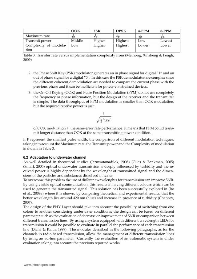
The transmitter generates an impulse of light of a fixed duration (250 ns) which allows tosupport a transmission at 1Mb/s in the case of an 16-PPM modulation or at 2Mb/s in the caseof a 4-PPM. The choice of LED wavelength has been done to maximize the power of receivedsignal as illustrated below (Figure 8).Particular attention has been posed on the circuit for the reception, since the reciprocal dis-tance of the underwater devices cannot be fixed in advance and the receiver has to maintainhis functioning in all the coverage area of the transmitter.The receiver has been designed considering different blocks: a photodiode; a transresistanceamplifier, to have a conversion from current to voltage; a bandpass filter to eliminate noise
www.intechopen.com

Prospects and Problems of Optical Diffuse Wireless Communication for Underwater Wireless Sensor Networks (UWSNs) 19
Fig. 7. Experimental set-up for point-to-point tests (a) - Bidirectional Transceiver (b)
below 10 kHz and above 20 MHz; an Automatic Gain Control (AGC), based on a Linear Tech-nology LT1006, used to amplify the signal received by the first part of the circuit and to au-tomatically increase or decrease the gain according to the signal amplitude; a comparator, todetermine the output value by fixing a threshold.The receiver has been implemented by using the following component: Si PIN photodiodeHamamatsu S5971 - high-speed photodiodes, with 1mm2 surface area. To evaluate the betterwavelength for the transmitter Table 5 has been compiled considering the absorption coef-ficients for clear water and the photodiode sensitivity reported in the component datasheet.The output current of the photodiode is proportional to:
S × e−k(d)
× P (11)
where S is sensitivity an P is the power in watts, d the distance and k the absorption coefficient.Figure 8 shows how the output current varies according to distance for different wavelengthsof light, by using the equation 11.Due to the severe attenuation in water, the output current for infrared is less than forblue/green light at 10m, even if the sensitivity of the photodiode is higher for infrared. Itis possible to note that red light outperforms green light up to 1.5/2 m but blue and green arebetter beyond. Taking into account the previous results, also considering that the attenuationis strongly influenced by turbidity, the better choice appear to be blue or green light. Theseconsiderations are very important because the system performance is determined by the de-tector when signal attenuation along a wireless link is considered. It is crucial for the receiverto detect low-level optical signals maintaining a Signal-to-Noise Ratio (SNR) sufficiently largeto yield an acceptable Bit Error Rate (BER).The receiver circuit has been tested in air and in water. Tests in clear water allows to receivecorrectly the transmitted sequence generated by the system (Figure 7) up to 2 meters: a moreaccurate evaluation of the BER is planned for turbid water. Considering the limitation of theavailable testbed, tests in air been performed at different distances: a reception of the trans-mitted sequence is possible starting from few centimeters, since the AGC avoids saturation,up to 10 meters, while below light impulses are not clearly detected. Even if the AGC stagehas to be modified to allow the reception in case of higher distances, considering that our
www.intechopen.com
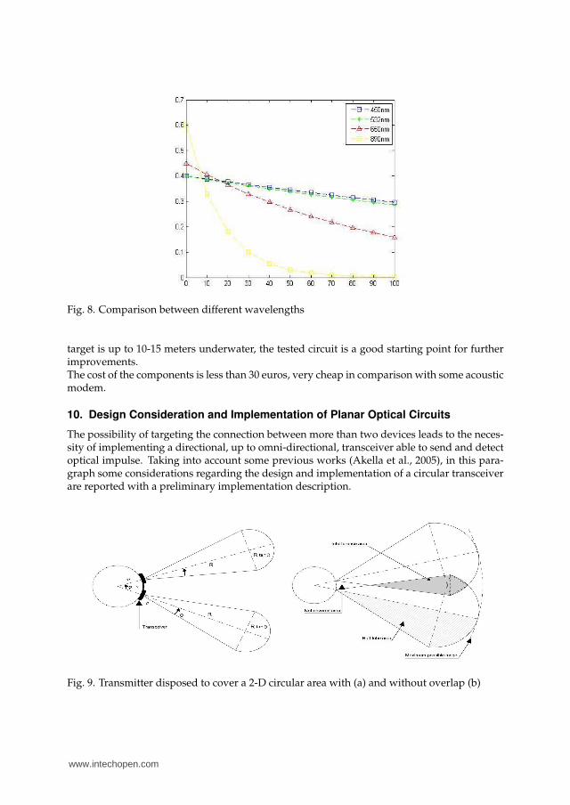
Fig. 8. Comparison between different wavelengths
target is up to 10-15 meters underwater, the tested circuit is a good starting point for furtherimprovements.The cost of the components is less than 30 euros, very cheap in comparison with some acousticmodem.
10. Design Consideration and Implementation of Planar Optical Circuits
The possibility of targeting the connection between more than two devices leads to the neces-sity of implementing a directional, up to omni-directional, transceiver able to send and detectoptical impulse. Taking into account some previous works (Akella et al., 2005), in this para-graph some considerations regarding the design and implementation of a circular transceiverare reported with a preliminary implementation description.
Fig. 9. Transmitter disposed to cover a 2-D circular area with (a) and without overlap (b)
www.intechopen.com

Prospects and Problems of Optical Diffuse Wireless Communication for Underwater Wireless Sensor Networks (UWSNs) 21
In particular the collocation of components (LED or photodiodes) on a 2D structure is con-sidered. Assuming that n transmitter are placed at equal distance gaps on the circular node(radius r), considering that the diameter of a transmitter is 2ρ:
τ =2πr − 2nρ
n(12)
The angular difference between any two neighboring transceiver is given as:
ϕ = 3600 τ
2πr(13)
The coverage area L of a single transmitter can be given by (Akella et al., 2005):
L = R2tan(ϑ) + 0.5πRtan(ϑ)2 (14)
Two cases can happen for the effective coverage area C of a single transmitter, based on thevalue of ϕ, θ, R, and r:
1. if coverage area of the neighbor transmitter do not overlap (Figure 9):
Rtan(ϑ) ≤ (R + r)tan(0.5ϕ) (15)
In this case, the effective coverage area is equivalent to the coverage area, i.e. C=L.
2. Coverage area of the neighbor transmitter overlap (Figure 9):
Rtan(ϑ) > (R + r)tan(0.5ϕ) (16)
In this case, the effective coverage area is equivalent to the coverage area excludingthe area that interferes with the neighbor transceiver. If I is the interference area thatoverlaps with the neighbor transmitter’s coverage, then C = L-I. Considering that thetarget of our work is to have a directional or at least omni-directional a good designapproach should minimize the interfere area.
If the target is to have a transmission and reception of data by using all the elements placedon the circular structure, the overlap is not a problem for the communication. But, since thefinal idea is to add the possibility of supporting also a directional communication in which asingle LED could be activated, the idea is to minimize the interference between adjacent LEDsand receivers.Taking into account the previous circuits, a 2-d transceiver has been implemented. The LEDsdisposition on a 2-d structure has been performed using 12 Ledman LL1503PLBL1-301 blueLED (with 300 of FOV) disposed on a circular disk of 10 cm diameter. The reduction of theoverlap between the signal generated by each LED has been targeted so to allow the possibilityof supporting also a directional transmission, by using only one or a reduced set of LEDs. Thesame approach has been considered for the placement of the photodiodes for the 2-d receiver.Tests of the transmitter have been carried out by using a single receiver, equipped with aSFH-2013P photodiode. Different measures have been considered at different distances. Theprofile of the received optical signal, determined by considering the maximum value in a line-of-sight condition and the minimum value which is measured between a LED and another,show that the generated light impulses is uniformly distributed on the surface. Tests on thereceiver have shown a performance decrease in comparison with the point-to-point circuitdue to the noise generated by the photodiodes which are not directly exposed to the lightimpulses. Nevertheless a reception up to 4 meters in air can be achieved.
www.intechopen.com
11. Future Research Directions
Starting from the previous described results, the creation of an innovative long survival op-tical Underwater Wireless Sensor Network (UWSN) could be targeted. It will able to sense,compute, communicate and cooperate in an underwater environment by using long-survival,low-cost and eventually disposable nodes. Innovative approaches could be developed to ad-dress:
1. wireless, adaptive and low-power optical underwater communication;
2. underwater energy scavenging and harvesting;
3. autonomous and self-governing behavior of the nodes in the underwater environment,including intelligent energy storing and utilization, to guarantee long-term operationunder a wide range of conditions and avoid frequent and costly rescue procedures.
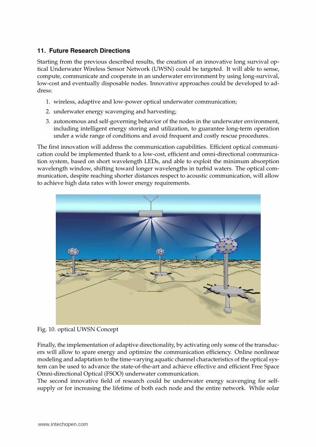
The first innovation will address the communication capabilities. Efficient optical communi-cation could be implemented thank to a low-cost, efficient and omni-directional communica-tion system, based on short wavelength LEDs, and able to exploit the minimum absorptionwavelength window, shifting toward longer wavelengths in turbid waters. The optical com-munication, despite reaching shorter distances respect to acoustic communication, will allowto achieve high data rates with lower energy requirements.
Fig. 10. optical UWSN Concept
Finally, the implementation of adaptive directionality, by activating only some of the transduc-ers will allow to spare energy and optimize the communication efficiency. Online nonlinearmodeling and adaptation to the time-varying aquatic channel characteristics of the optical sys-tem can be used to advance the state-of-the-art and achieve effective and efficient Free SpaceOmni-directional Optical (FSOO) underwater communication.The second innovative field of research could be underwater energy scavenging for self-supply or for increasing the lifetime of both each node and the entire network. While solar
www.intechopen.com

Prospects and Problems of Optical Diffuse Wireless Communication for Underwater Wireless Sensor Networks (UWSNs) 23
power can be exploited on the water surface and in shallow but clear waters, other techniquesmust be explored for producing and storing energy in a general underwater environment.Terrestrial energy scavenging for artificial artifacts and autonomous sensors relies mainly onexploiting environmental vibrations, converting mechanical energy in electrical energy. In thestatic underwater nodes, random movements forced by the water flow, underwater currentsand noise, can be exploited to perform underwater energy scavenging (D.Zhu, 2010). Thedelicate equilibrium between energy harvesting, storage and consumption is to addressed bydeveloping adaptive behavior, to optimize the survivability of both the nodes and the entirenetwork.The third field of research should address the development of low-power, low-cost miniatur-ized nodes able to sense, compute, communicate and cooperate in an aquatic environment.The development of new nodes, with volumes that are orders of magnitude smaller than cur-rent generation equipments, will allow the development of new applications, where tiny and,eventually, disposable nodes will be able to perform 4D monitoring of aquatic environments.The increased density of the network, which will be possible thank to the miniaturization andlow-cost of the nodes, will allow to compensate for the relatively short range of the under-water optical communication channel, which is, as shown, well below 100m. Furthermore,in settings where environmental issues are of limited concern, the use of low-cost disposablenodes will avoid frequent and costly rescue procedures, by simply adding new nodes to areasnot covered by the network or to overcome the malfunctioning of old nodes.The development of the previous described fields of research could lead to the implementationof low-cost optically communicating nodes, able to be deployed with low accuracy on the areaof interest, and capable of self-configuring as a sensing network as depicted in Figure 10.
12. References
Akella, J., Liu, C., Partyka, D., Yuksel, M., Kalyanaraman, S. & Dutta, P. (2005). Buildingblocks for mobile free-space-optical networks, Second IFIP International Conference onWireless and Optical Communications Networks, 2005. WOCN 2005., pp. 164 – 168.
Akyildiz, I. F., Pompili, D. & Melodia, T. (2005). Underwater acoustic sensor networks: re-search challenges, Ad Hoc Networks 3(3): 257 – 279.
Akyldiz, I. F., Su, W., Sankarasubramaniam, Y. & Cayirci, E. (2001). A survey on sensor net-work.
Al-Shamma’a, A., Shaw, A. & Saman, S. (2004). Propagation of electromagnetic waves atmhz frequencies through seawater, Antennas and Propagation, IEEE Transactions on52(11): 2843–2849.
Ambalux (2008). http://www.ambalux.com.Anguita, D., Brizzolara, D., Ghio, A. & Parodi, G. (2008). Smart plankton: a nature inspired
underwater wireless sensor network, Natural Computation, 2008. ICNC ’08. Fourth In-ternational Conference on 7: 701 –705.
Anguita, D., Brizzolara, D. & Parodi, G. (2009). Building an underwater wireless sensor net-work based on optical communication: Research challenges and current results, Sen-sor Technologies and Applications, 2009. SENSORCOMM ’09. Third International Confer-ence on pp. 476 –479.
Anguita, D., Brizzolara, D. & Parodi, G. (2010). Design and implementation of hdl mod-ules and circuits for underwater optical wireless communication, Proceedings of the9th WSEAS International Conference on TELECOMMUNICATIONS and INFORMAT-ICS pp. 132 – 137.
www.intechopen.com

Baiden, G. & Bissiri, Y. (2007). High bandwidth optical networking for underwater untetheredtelerobotic operation, OCEANS 2007, pp. 1–9.
Baiden, G., Bissiri, Y. & Masoti, A. (2009). Paving the way for a future underwater omni-directional wireless optical communication systems, Ocean Engineering 36(9-10): 633– 640.
Chancey, M. A. (2007). Degree of master of science: Short range underwater optical commu-nication links.
C.X.Fan, F.Zhang, Xu, B. & Wu, C. (2001). Communication theory, Defense Industry Press.Dasalukunte, D. & Owall, V. (2008). A generic hardware mac for wireless personal area net-
work platforms, Proceedings of the 11th International Symposium on Wireless PersonalMultimedia Communication (WPMC’08) .
Diana, L. & Kahn, J. (1999). Rate-adaptive modulation techniques for infrared wireless com-munication, Proceedings of ICC ’99 1: 597–603.
Doniec, M., Detweiler, C., Vasilescu, I. & Rus, D. (2010). Using optical communication forremote underwater robot operation.
Doniec, M., Vasilescu, I., Chitre, M., Detweiler, C., Hoffmann-Kuhnt, M. & Rus, D. (2009).Aquaoptical: A lightweight device for high-rate long-range underwater point-to-point communication, OCEANS 2009, MTS/IEEE Biloxi - Marine Technology for OurFuture: Global and Local Challenges pp. 1 –6.
D.Zhu, M.J.Tudor, S. (2010). Strategies for increasing the operating frequency range of vibra-tion energy harvesters: a review, Measurement Science and Technology .
Fair, N., Chave, A., Freitag, L., Preisig, J., White, S., Yoerger, D. & Sonnichsen, F. (2006). Opticalmodem technology for seafloor observatories, OCEANS 2006 pp. 1–6.
Farr, N., Chave, A., Freitag, L., Preisig, J., White, S., Yoerger, D. & Titterton, P. (2005). Op-tical modem technology for seafloor observatories, OCEANS, 2005. Proceedings ofMTS/IEEE pp. 928–934 Vol. 1.
Feng Lu, Sammy Lee, J. M. C. S. (2009). Low-cost medium-range optical underwater modem,WUWNET 2009, pp. 1–6.
Fibre, W. (2008). http://www.wirelessfibre.co.uk/.Ghassemlooy, Z., Popoola, W., Rajbhandari, S., Amiri, M. & Hashemi, S. (2007). A synopsis of
modulation techniques for wireless infrared communication, ICTON MediterraneanWinter Conference, 2007. ICTON-MW 2007, pp. 1–6.
Giles, J. & Bankman, I. (2005). Underwater optical communications systems. part 2: ba-sic design considerations, IEEE Military Communications Conference. MILCOM 2005.pp. 1700–1705 Vol. 3.
Hanson, F. & Radic, S. (2008). High bandwidth underwater optical communication, AppliedOptics 36: 277–283.
Ito, Y., Haruyama, S. & Nakagawa, M. (2008a). Short-range underwater wireless communica-tion using visible light leds.
Ito, Y., Haruyama, S. & Nakagawa, M. (2008b). Short-range underwater wireless communica-tion using visible light leds.
Jaruwatanadilok, S. (2008). Underwater wireless optical communication channel modelingand performance evaluation using vector radiative transfer theory, Selected Areas inCommunications, IEEE Journal on 26(9): 1620–1627.
Kahn, J. & Barry, J. (1997). Wireless infrared communications, Proceedings of the IEEE 85(2): 265–298.
www.intechopen.com

Prospects and Problems of Optical Diffuse Wireless Communication for Underwater Wireless Sensor Networks (UWSNs) 25
Kedar, D. (2007). Underwater sensor network using optical wireless communication, SPIENewsroom - The International Society for Optical Engineering .
Lanbo, L., Shengli, Z. & Jun-Hong, C. (2008). Prospects and problems of wireless communica-tion for underwater sensor networks, Wirel. Commun. Mob. Comput. 8(8): 977–994.
Lee, D. & Kahn, J. (1999). Coding and equalization for ppm on wireless infrared channels,IEEE Transaction on Communication 47: 255–260.
Lee, S., Mounzer, J., Mirza, D. & Schurgers, C. (2008). Demo abstract: Low cost, mediumrange optical, communication for underwater test beds, The Third ACM InternationalWorkshop on UnderWater Networks (WUWNet).
Liu, Y. & Ge, X. (2006). Underwater laser sensor network: A new approach for broadbandcommunication in the underwater, Proceedings of the 5th WSEAS International Confer-ence on Telecommunications and Informatics, pp. 421–425.
Lucas, J., Al-ShammaŠa, A., Seim, J., Loehr, W., Puchbauer, G. & McGregor, D. (2004). Under-water communications using electromagnetic waves (emcomms), Vol. Proceeding ofEuropean Conference on Marine Science and Ocean Technology.
Ma, H. (2003). Research on optical modulation and demodulation techniques in mobile atmo-spheric laser communication, National University of Defense Technology.
Malik, D., Joseph, M. & John, R. (1996). Performance of pulse-position on measured non-directed indoor infrared channels, IEEE Transaction on Communications 44: 173–177.
Meihong, S., Xinsheng, Y. & Fengli, Z. (2009). The evaluation of modulation techniques forunderwater wireless optical communications, Communication Software and Networks,International Conference on 0: 138–142.
Meihong, S., Xinsheng, Y. & Zhangguo, Z. (2009). The modified ppm modulation for under-water wireless optical communication, Communication Software and Networks, Interna-tional Conference on 0: 173–177.
Pang, W., Chew, W., Choong, F. & Teoh, E. (2007). Vhdl modeling of the ieee802.11b dcf mac,Proceedings of the 6th WSEAS International Conference on Instrumentation, Measurement,Circuits and Systems .
Park, H. & Barry, J. (1995). Modulation analysis for wireless infrared communications, Com-munications, 1995. ICC ’95 Seattle, ’Gateway to Globalization’, 1995 IEEE InternationalConference on, Vol. 2, pp. 1182–1186 vol.2.
Puccinelli, D. & Haenggi, M. (2005). Wireless sensor networks: applications and challenges ofubiquitous sensing, IEEE, Circuits and Systems Magazine.
Shelley, T. (2005). Radio waves transmit information underwater, Eureka Magazine.Shill, F., Zimmer, U. R. & Trumpi, J. (2004). Visible spectrum optical communication and
distance sensing for underwater applications.Singh, S., Grund, M., Bingham, B., Eustice, R., Singh, H. & Freitag, L. (2006). Underwater
acoustic navigation with the whoi micro-modem, OCEANS 2006, pp. 1–4.Smart, J. (2005). Underwater optical communications systems part 1: variability of water op-
tical parameters, IEEE Military Communications Conference. MILCOM 2005. pp. 1140–1146 Vol. 2.
Tivey, M., Fucile, P. & Sichel, E. (2004). A low power, low cost, underwater optical communi-cation system, Ridge 2000 Events pp. 27–29.
V. Hsu, J. M. K. & Pister, K. S. J. (1998). Wireless communications for smart dust, ElectronicsResearch Laboratory Technical Memorandum Number M98/2.
www.intechopen.com

Vasilescu, I., Detweiler, C. & Rus, D. (2007). Aquanodes: an underwater sensor network,WuWNet ’07: Proceedings of the second workshop on Underwater networks, ACM, NewYork, NY, USA, pp. 85–88.
Vasilescu, I., Kotay, K., Rus, D., Dunbabin, M. & Corke, P. (2005). Data collection, storage,and retrieval with an underwater sensor network, SenSys ’05: Proceedings of the 3rdinternational conference on Embedded networked sensor systems, ACM, New York, NY,USA, pp. 154–165.
WiseLab (2010). http://www.wise-laboratory.it/test/index.htm, DIBE: Department of Biophys-ical and Electronic Engineering .
Yan, H., Zhou, S., Shi, Z. J. & Li, B. (2007). A dsp implementation of ofdm acoustic modem,WuWNet ’07: Proceedings of the second workshop on Underwater networks, ACM, NewYork, NY, USA, pp. 89–92.
www.intechopen.com

Wireless Sensor Networks: Application-Centric DesignEdited by Yen Kheng Tan
ISBN 978-953-307-321-7Hard cover, 492 pagesPublisher InTechPublished online 14, December, 2010Published in print edition December, 2010
InTech EuropeUniversity Campus STeP Ri Slavka Krautzeka 83/A 51000 Rijeka, Croatia
InTech ChinaUnit 405, Office Block, Hotel Equatorial Shanghai No.65, Yan An Road (West), Shanghai, 200040, China
Phone: +86-21-62489820
Over the past decade, there has been a prolific increase in the research, development and commercialisationof Wireless Sensor Networks (WSNs) and their associated technologies. WSNs have found application in avast range of different domains, scenarios and disciplines. These have included healthcare, defence andsecurity, environmental monitoring and building/structural health monitoring. However, as a result of the broadarray of pertinent applications, WSN researchers have also realised the application specificity of the domain; itis incredibly difficult, if not impossible, to find an application-independent solution to most WSN problems.Hence, research into WSNs dictates the adoption of an application-centric design process. This book is notintended to be a comprehensive review of all WSN applications and deployments to date. Instead, it is acollection of state-of-the-art research papers discussing current applications and deployment experiences, butalso the communication and data processing technologies that are fundamental in further developing solutionsto applications. Whilst a common foundation is retained through all chapters, this book contains a broad arrayof often differing interpretations, configurations and limitations of WSNs, and this highlights the diversity of thisever-changing research area. The chapters have been categorised into three distinct sections: applicationsand case studies, communication and networking, and information and data processing. The readership of thisbook is intended to be postgraduate/postdoctoral researchers and professional engineers, though some of thechapters may be of relevance to interested master’s level students.
How to referenceIn order to correctly reference this scholarly work, feel free to copy and paste the following:
Davide Anguita, Davide Brizzolara and Giancarlo Parodi (2010). Prospects and Problems of Optical DiffuseWireless Communication for Underwater Wireless Sensor Networks, Wireless Sensor Networks: Application-Centric Design, Yen Kheng Tan (Ed.), ISBN: 978-953-307-321-7, InTech, Available from:http://www.intechopen.com/books/wireless-sensor-networks-application-centric-design/prospects-and-problems-of-optical-diffuse-wireless-communication-for-underwater-wireless-sensor-netw
www.intechopen.com

Phone: +385 (51) 770 447 Fax: +385 (51) 686 166www.intechopen.com
Phone: +86-21-62489820 Fax: +86-21-62489821

© 2010 The Author(s). Licensee IntechOpen. This chapter is distributedunder the terms of the Creative Commons Attribution-NonCommercial-ShareAlike-3.0 License, which permits use, distribution and reproduction fornon-commercial purposes, provided the original is properly cited andderivative works building on this content are distributed under the samelicense.