propulsion control of air-suspended hybrid linear motor vehicle … · 2010-09-14 · 2...
TRANSCRIPT
803
Propulsion Control of Air-Suspended Hybrid Linear Motor Vehicle Based on Decoupled Control in SLIM/LSM
(*) K. Yoshida, H. Takami, T. Yoshida, (**)M. Suganuma, K. Ohshima (*) Kyushu University, 6-10-1 Hakozaki Higashi-ku, Fukuoka 812-8581, Japan
Phone: +81-92-642-3905, Fax : +81-92-633-2710, e-mail: [email protected]
(**) Nippon Otis Elevator Co., LTD, 2700-1 Koike Shibayama-machi Sanbu-gun, Chiba 289-1693, Japan
Phone : +81-479-77-2113, Fax : +81-479-77-1771, e-mail : [email protected]
Keywords
decoupled control, hybrid linear motor
Abstract
Practical-scale air-suspended vehicle is driven by hybrid linear motor (LM) and levitated by air-suspension. The vehicle is driven by single-sided linear induction motor (SLIM) in flat and gentle slope sections of the guideay, and driven by linear synchronous motor (LSM) in steep slope section.
This paper presents propulsion control of air-suspended hybrid LM vehicle based on decoupled control of thrust and normal forces in SLIM and LSM sections. Experimental results show that the vehicle can be controlled stably on 10% steep slope with relaxation curve and can be controlled smoothly between SLIM and LSM sections on the slope by switching from SLIM to LSM mode or from LSM to SLIM mode.
1 Introduction Maglev linear motor transit system, which is good for earth environment and makes
possible super high-speed and mass transportation, enters upon the stage of practical use [1]. Shanghai Maglev transport system [2] is to be opened for business in Autumn 2003. The authors have studied and developed a new air-suspended hybrid linear motor vehicle which consists of “air-suspended system” and “hybrid linear motor” [3], [4]. Practical-scale air-suspended hybrid linear motor vehicle is driven by linear motor and levitated by
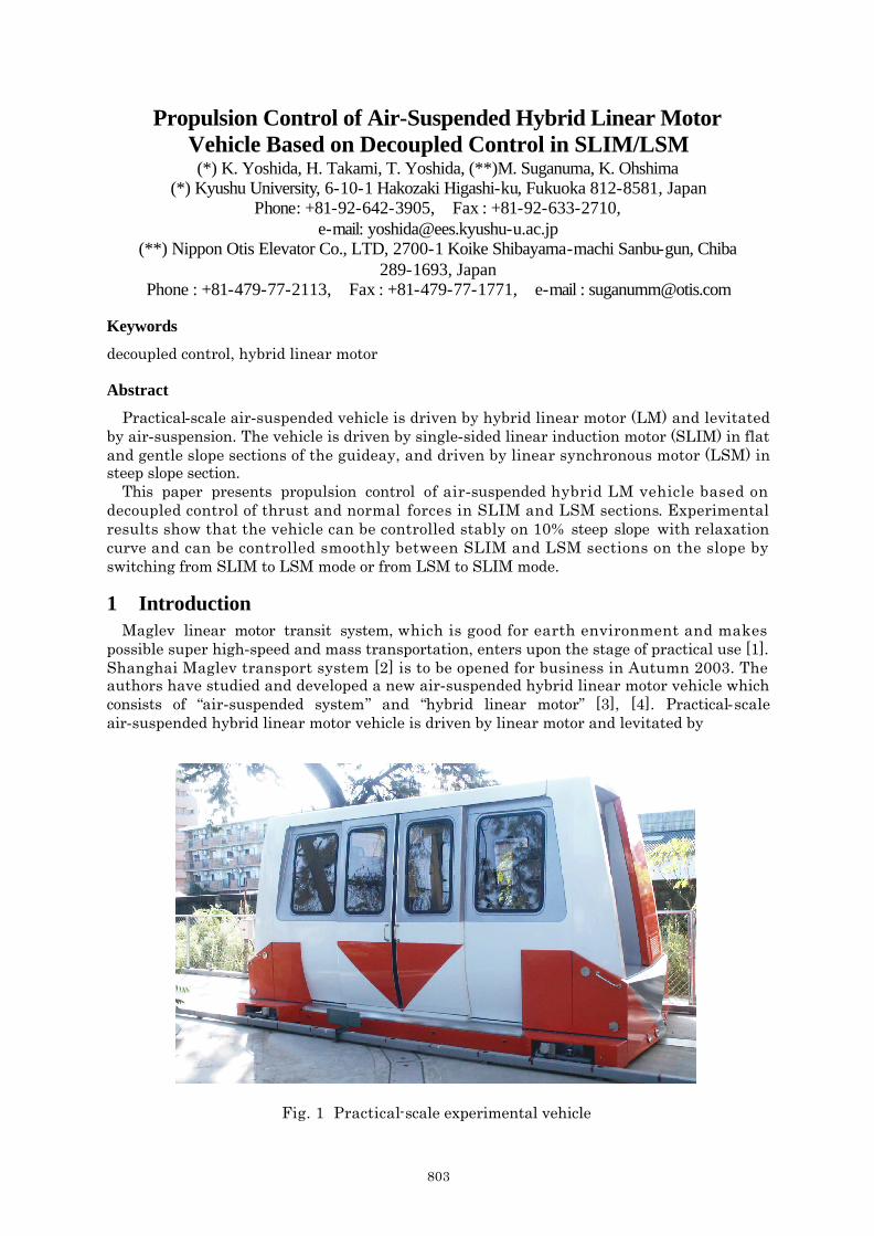
Fig. 1 Practical-scale experimental vehicle

804
air-suspension. This transit system can accommodate to steep slope with very low noise. The most distinct characteristics of this system is that the vehicle is driven by SLIM or LSM to correspond to geographical features with steep slope. The vehicle with LM armature on board operates as SLIM on reaction plate guideway in flat and gentle slope sections, and as LSM on DC magnet guideway in steep slope sections.
This paper presents propulsion control of air-suspended hybrid linear motor vehicle based on decoupled control of thrust and normal forces in SLIM and LSM. The attractive normal force in SLIM and LSM increases equivalent mass of the vehicle. It is very useful for the vehicle operation to control independently thrust and attractive normal forces in SLIM and LSM [3], [4]. Experimental results show that the vehicle can be controlled stably and smoothly running up and down on 10% steep slope with relaxation curve.
2 Air-Suspended Hybrid Linear Motor Vehicle and Guideway Figure 1 shows air-suspended hybrid linear motor vehicle. This experimental vehicle is
practical-scale and accommodates about ten people. The vehicle is levitated by air-suspension. There are 10 airpads on the bottom of the
vehicle. On the other hand, the vehicle is propelled by linear motor. The vehicle is driven by SLIM in flat and gentle slope sections, and driven by LSM in steep slope section. The vehicle with two armatures mounted independently on straight-line at the front and the rear on board is about 4ton in weight and 4.56m in length. The SLIM section in the guideway which
Table 1 Specifications of experimental vehicle and track
Vehicle
Propulsion system
Suspension system
Guidance system
Vehicle size (mm)
Weight (ton)
Hybrid linear motor (SLIM and LSM)
Air-suspension
Side-guideroller
4,560L× 2,225W× 2,461H
4.0
Track
Length (m)
Maximum gradient
24.5 (SLIM)
22.3 (LSM)
3.8% (SLIM)
10.0% (LSM)
Fig. 2 Side view of the guideway

805
consists of aluminum reaction plate with back-iron is about 24.5m in length including about 4.4m gentle slope. The LSM section in the guideway which consists of DC magnets with field winding is about 22.3m in length and is the maximum gradient of 10%. Table 1 shows the specifications of experimental vehicle and guideway. Figure 2 shows the side view of the guideway.
3 Control Strategy for Air-Suspended Hybrid Linear Motor Vehicle
3.1 Decoupled Control of Normal and Thrust Forces Decoupled control method of normal and thrust forces in a SLIM and LSM are derived from
analytical formulas for normal and thrust forces based on space harmonic analysis method [5], [6]. In this study, the field windings are discontinuous in consideration of practical use. Therefore normal and thrust forces in a LSM are calculated using finite element method (FEM) in order to derive these forces accurately. We also derived normal and thrust forces in a SLIM using FEM [7]. But these forces using FEM were not used and these ones using space harmonic analysis method were used in this experiment. We are planning to use these forces using FEM in the future.
The decoupled control laws for SLIM are given as a function of thrust forces Fx, normal forces Fz and airgap length δ [8]:
* SLIM * *1 ( , , )i I z i iI f F sf δ= (1)
* SLIM * *( / )i sf x zsf f F F= (2)
where subscript i =1, 2 represents variables of front and rear LM’s, and superscript * means command value in a controller. *
1iI is command effective value of armature current and *isf
is command slip-frequency respectively. On the other hand, decoupled control laws for LSM are also derived as a function of thrust
force, normal force and airgap length as follows [9]: * LSM * *
1 ( , , )i I z x iI f F F δ= (3)
0
* LSM * *0 ( , , )i x x z ix f F F δ= (4)
where *0ix represents command mechanical load-angle of the LSM.
The specifications of Hybrid LM are shown in Table2.
Table 2 Specifications of Hybrid LM
Item Value
Number of pole
Pole pitch
Width of primary iron core
Turn per phase
3
180mm
200mm
360
3.2 Control System for Air-Suspended Hybrid Linear Motor Vehicle Figure 3 shows a block diagram for propulsion and normal force controls in the hybrid
linear motor vehicle. The system consists of following items: (1) Patterns for propulsion
20x , 20xv and 20xa are patters of vehicle position, speed and acceleration, respectively.

806
(2) Motion control: This calculates command thrust force *
xF on a basis of PID controller and disturbance
observer which compensate a drag and mass of vehicle. (3) Calculation of thrust and normal forces of front and rear LM’s:
This allots well-balanced command thrust force to front and rear LM’s. In conversion region of LM from SLIM to LSM or from LSM to SLIM, normal force of LM is controlled so that the vehicle is levitated stably.
(4) Controllers for front and rear LM’s These are composed of decoupled controls for SLIM and LSM on a basis of Eqs. (1) - (4), switches of SLIM and LSM modes, transformation into 3-phase and current control. For making dimension of slip frequency in SLIM that of mechanical load-angle in LSM, a matching-integrator 2 / sπ and two matching-coefficients /π τ are adopted.
(5) VVVF inverter Two VVVF inverter are used to drive front and rear LM’s. Electric power is supplied from lead battery.
(6) Encoder and gap sensor These are used for measuring vehicle position x2, speed vx2, and front-, center- and rear-levitation heights zF, zC, zR.
3.3 Experimental System The calculation of motion control is carried out by one DSP. Its sampling time is 0.25ms.
The calculated data of command values of current * * * *1 1 2 2, , , u w u wi i i i are sent to two
CPU-Boards with common memory. The calculation of current control whose sampling time is 0.1ms is carried out by the CPU-Board. The calculated PWM signals are sent to VVVF inverter with an optical fiber cable. This control system is not much affected by noise. The experimental system is on board the vehicle. The vehicle is connected with ground by only side-guide-rollers.
Fig. 3 Block diagram of hybrid control system on board

807
4 Hybrid Propulsion and Levitation Experiment Figure 4 shows the experimental results of propulsion control in air-suspended hybrid
linear motor vehicle. In Fig.4, subscript of 0 shows the demand pattern and the other shows the experimental results. In the experiment, the vehicle is first levitated upward by about 15mm at standstill, and then is driven until 37.8m at the maximum speed of 3.6km/h. As shown in Fig. 4(a) and (b), vehicle position x2 and speed vx2 were controlled very well to follow the demand pattern x20 and vx20 in all sections including changing point from SLIM to LSM and from LSM to SLIM. Figure 4 (c) shows the levitation height at the center of the vehicle zC. Though the levitation height fluctuates a little, the air-suspended hybrid LM system has a sufficient mechanical clearance. Figure 4(d) shows effective values of primary current 1I . It corresponds to command value because the current control is carried out 0.1ms. Figure 4(e) and (f) show the slip-frequency and mechanical load-angle respectively. Based on the decoupled control law for SLIM or LSM, the effective value of primary current and
Fig. 4 Experimental results of hybrid propulsion and levitation control
(e) Slip-frequency
(b) Vehicle speed
(c) Levitation Height
(f) Mechanical load-angle
(a) Vehicle position
SLIM SLIM LSM
(d) Effective value of primary current
SLIM SLIM LSM

808
slip-frequency or mechanical load-angle are determined uniquely. From these results, it is found that the vehicle is controlled to follow the demand pattern
satisfactorily and is levitated stably in all sections including changing point from SLIM to LSM and from LSM to LIM by controlling independently the thrust and normal forces in SLIM and LSM.
5 Conclusions In this paper, we adapted decoupled control of normal and thrust forces in SLIM and LSM
to practical-scale air-suspended hybrid linear motor vehicle. High performance propulsion control including stable levitation experiment of practical-scale air-suspended hybrid linear motor vehicle has been carried out successfully in SLIM and LSM sections in full scale guideway of 37.8m. The vehicle could be driven at 3.6km/s on 10% steep slope and run through stably and continuously between SLIM and LSM section. At the region of 10% steep slope section, considerably stronger attractive normal force of LSM than that of SLIM is controlled stably.
6 References 1. S. Fujiwara: “Development and Running Test of the JR-Maglev”, Proc. of 7th ISMST, Oct. 2003, pp.
302-307
2. Xiangming Wu: “High-Speed Maglev Shanghai Demonstration Line”, Proc. of 7th ISMST, Oct. 2003, pp. 63-66
3. K. Yoshida, T. Yoshida, H. Takami, M. Suganuma, K. Ohshima: “High Performance Control of Air Suspended Hybrid Linear Motor Vehicle in SLIM Section”, Proc. of 7th ISMST, Oct. 2003, pp. 170-175
4. K. Yoshida, H. Takami, T. Yoshida, M. Suganuma, K. Ohshima: “A LIM/LSM Switching Strategy in Hybrid Linear Transport Maglev System”, Proc. of 7th ISMST, Oct. 2003, pp. 176-181
5. K. Yoshida, S. Nonaka: “Levitation Force in Single -Sided Linear Induction Motors for High-speed Ground Transportation”, IEEE Transactions on Magnetics, MAG-11, No.6, Nov. 1975, pp.1717-1719
6. K. Yoshida, H. Weh: “Theory of a Controlled-PM Linear Synchronous Motor”, Proc. of 10th Int. Conf. on Maglev’88, 1988, pp.259-268
7. K. Yoshida, T. Yoshida, K. Noda, Y. Takahara: “Analysis of Thrust and Attractive-Normal Forces in Air-Suspended LIM Vehicle”, Proc. of 7th ISMST, Oct. 2003, pp. 203-208
8. K. Yoshida, L. Shi, T. Yoshida, “A Proposal of Decoupled-Control of Attractive-Normal and Thrust Forces in a SLIM for Maglev Vehicle”, Proc. of the 6th Int. Conf. ELECTRIMACS, Sept. 1999, pp.221-226
9. K. Yoshida, H.Takami, L. Shi: “Decoupled-Control Method for Levitation and Propulsion in Amphibious Train Marine Express”, Memories of faculty of Engineering, Kyushu University, Vol.55, No.4, 1995, pp.467-489