proposed lrfd specifications for noncomposite steel box … · 2019-09-10 · this report addresses...
TRANSCRIPT
Proposed LRFD Specifications for Noncomposite Steel Box-Section Members FINAL REPORT
Publication No. FHWA-HIF-19-063Infrastructure Office of Bridges and Structures
July 2019
FOREWORD
This report provides documentation of a comprehensive research effort on the behavior and design of non-composite steel box-section members for bridges. The AASHTO Committee on Bridges and Structures, Technical Committee T-14 (Structural Steel) identified this topic as a high priority for improvement to the AASHTO LRFD Bridge Design Specifications. This work provides a new methodology and associated provisions that are generally applicable, conceptually unified, and clearly documented and illustrated, which will lead to more economical and effective use of non-composite steel box-section members in bridge construction. Flowcharts and design examples are also provided which provides step-by-step guidance to practicing engineers and owners. The proposed LRFD specifications have been endorsed by AASHTO COBS T-14 and will be considered for inclusion in the 9th Edition of AASHTO LRFD Bridge Design Specifications.
The quality of the final products from this effort benefitted from the contributions of the team of reviewers including Tom Macioce (Pennsylvania DOT), and AASHTO COBS T-14.
Joseph L. Hartmann, Ph.D., P.E. Director, Office of Bridges and Structures
Notice This document is disseminated under the sponsorship of the U.S. Department of Transportation (USDOT) in the interest of information exchange. The U.S. Government assumes no liability for the use of the information contained in this document.
The U.S. Government does not endorse products or manufacturers. Trademarks or manufacturers’ names appear in this report only because they are considered essential to the objective of the document.
Quality Assurance Statement The Federal Highway Administration (FHWA) provides high-quality information to serve Government, industry, and the public in a manner that promotes public understanding. Standards and policies are used to ensure and maximize the quality, objectivity, utility, and integrity of its information. FHWA periodically reviews quality issues and adjusts its programs and processes to ensure continuous quality improvement.
Cover Photos: Left and Top Right, © 2019 HDR; Bottom Right © Michael Baker
TECHNICAL REPORT DOCUMENTATION PAGE
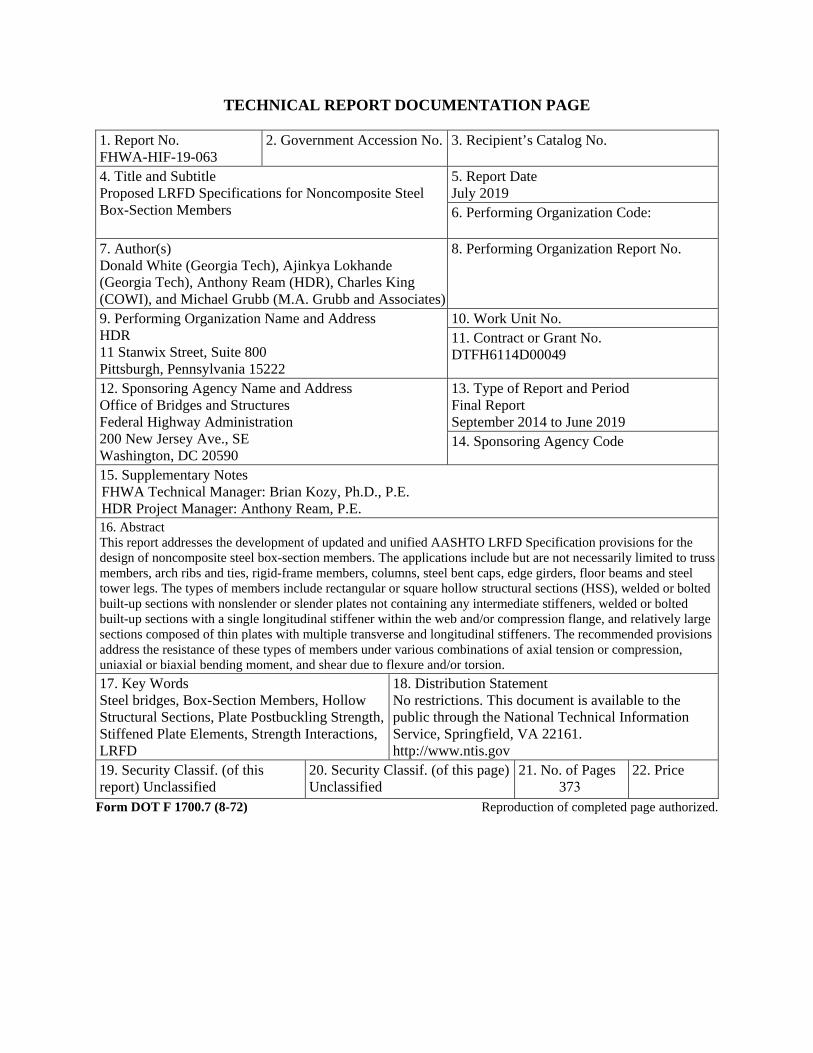
1. Report No.FHWA-HIF-19-063
2. Government Accession No. 3. Recipient’s Catalog No.
4. Title and SubtitleProposed LRFD Specifications for Noncomposite SteelBox-Section Members
5. Report DateJuly 20196. Performing Organization Code:
7. Author(s)Donald White (Georgia Tech), Ajinkya Lokhande(Georgia Tech), Anthony Ream (HDR), Charles King(COWI), and Michael Grubb (M.A. Grubb and Associates)
8. Performing Organization Report No.
9. Performing Organization Name and AddressHDR11 Stanwix Street, Suite 800Pittsburgh, Pennsylvania 15222
10. Work Unit No.11. Contract or Grant No.DTFH6114D00049
12. Sponsoring Agency Name and AddressOffice of Bridges and StructuresFederal Highway Administration200 New Jersey Ave., SEWashington, DC 20590
13. Type of Report and PeriodFinal ReportSeptember 2014 to June 201914. Sponsoring Agency Code
15. Supplementary NotesFHWA Technical Manager: Brian Kozy, Ph.D., P.E.HDR Project Manager: Anthony Ream, P.E.16. AbstractThis report addresses the development of updated and unified AASHTO LRFD Specification provisions for thedesign of noncomposite steel box-section members. The applications include but are not necessarily limited to trussmembers, arch ribs and ties, rigid-frame members, columns, steel bent caps, edge girders, floor beams and steeltower legs. The types of members include rectangular or square hollow structural sections (HSS), welded or boltedbuilt-up sections with nonslender or slender plates not containing any intermediate stiffeners, welded or boltedbuilt-up sections with a single longitudinal stiffener within the web and/or compression flange, and relatively largesections composed of thin plates with multiple transverse and longitudinal stiffeners. The recommended provisionsaddress the resistance of these types of members under various combinations of axial tension or compression,uniaxial or biaxial bending moment, and shear due to flexure and/or torsion.17. Key WordsSteel bridges, Box-Section Members, HollowStructural Sections, Plate Postbuckling Strength,Stiffened Plate Elements, Strength Interactions,LRFD
18. Distribution StatementNo restrictions. This document is available to thepublic through the National Technical InformationService, Springfield, VA 22161.http://www.ntis.gov
19. Security Classif. (of thisreport) Unclassified
20. Security Classif. (of this page)Unclassified
21. No. of Pages373
22. Price
Form DOT F 1700.7 (8-72) Reproduction of completed page authorized.

iii
SI* (MODERN METRIC) CONVERSION FACTORS APPROXIMATE CONVERSIONS TO SI UNITS
Symbol When You Know Multiply By To Find Symbol LENGTH
in inches 25.4 millimeters mm ft feet 0.305 meters m yd yards 0.914 meters m mi miles 1.61 kilometers km
AREA in2 square inches 645.2 square millimeters mm2
ft2 square feet 0.093 square meters m2
yd2 square yard 0.836 square meters m2
ac acres 0.405 hectares ha mi2 square miles 2.59 square kilometers km2
VOLUME fl oz fluid ounces 29.57 milliliters mL gal gallons 3.785 liters L ft3 cubic feet 0.028 cubic meters m3
yd3 cubic yards 0.765 cubic meters m3
NOTE: volumes greater than 1000 L shall be shown in m3
MASS oz ounces 28.35 grams glb pounds 0.454 kilograms kgT short tons (2000 lb) 0.907 megagrams (or "metric ton") Mg (or "t")
TEMPERATURE (exact degrees) oF Fahrenheit 5 (F-32)/9 Celsius oC
or (F-32)/1.8 ILLUMINATION
fc foot-candles 10.76 lux lx fl foot-Lamberts 3.426 candela/m2 cd/m2
FORCE and PRESSURE or STRESS lbf poundforce 4.45 newtons N lbf/in2 poundforce per square inch 6.89 kilopascals kPa
APPROXIMATE CONVERSIONS FROM SI UNITS Symbol When You Know Multiply By To Find Symbol
LENGTHmm millimeters 0.039 inches in m meters 3.28 feet ft m meters 1.09 yards yd km kilometers 0.621 miles mi
AREA mm2 square millimeters 0.0016 square inches in2
m2 square meters 10.764 square feet ft2
m2 square meters 1.195 square yards yd2
ha hectares 2.47 acres ac km2 square kilometers 0.386 square miles mi2
VOLUME mL milliliters 0.034 fluid ounces fl oz L liters 0.264 gallons gal m3 cubic meters 35.314 cubic feet ft3
m3 cubic meters 1.307 cubic yards yd3
MASS g grams 0.035 ounces ozkg kilograms 2.202 pounds lbMg (or "t") megagrams (or "metric ton") 1.103 short tons (2000 lb) T
TEMPERATURE (exact degrees) oC Celsius 1.8C+32 Fahrenheit oF
ILLUMINATION lx lux 0.0929 foot-candles fc cd/m2 candela/m2 0.2919 foot-Lamberts fl
FORCE and PRESSURE or STRESS N newtons 0.225 poundforce lbf kPa kilopascals 0.145 poundforce per square inch lbf/in2
iv
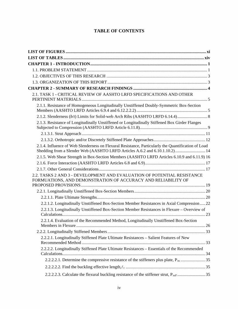
TABLE OF CONTENTS
LIST OF FIGURES ................................................................................................................................... xi LIST OF TABLES ................................................................................................................................... xiv CHAPTER 1 - INTRODUCTION ............................................................................................................. 1
1.1. PROBLEM STATEMENT ................................................................................................................ 1 1.2. OBJECTIVES OF THIS RESEARCH .............................................................................................. 3 1.3. ORGANIZATION OF THIS REPORT ............................................................................................. 3
CHAPTER 2 - SUMMARY OF RESEARCH FINDINGS ..................................................................... 4 2.1. TASK 1 - CRITICAL REVIEW OF AASHTO LRFD SPECIFICATIONS AND OTHER PERTINENT MATERIALS ..................................................................................................................... 5
2.1.1. Resistance of Homogeneous Longitudinally Unstiffened Doubly-Symmetric Box-Section Members (AASHTO LRFD Articles 6.9.4 and 6.12.2.2.2) .................................................................. 5 2.1.2. Slenderness (b/t) Limits for Solid-web Arch Ribs (AASHTO LRFD 6.14.4) ............................ 8 2.1.3. Resistance of Longitudinally Unstiffened or Longitudinally Stiffened Box Girder Flanges Subjected to Compression (AASHTO LRFD Article 6.11.8)............................................................... 9
2.1.3.1. Strut Approach ................................................................................................................... 11 2.1.3.2. Orthotropic and/or Discretely Stiffened Plate Approaches ................................................ 12
2.1.4. Influence of Web Slenderness on Flexural Resistance, Particularly the Quantification of Load Shedding from a Slender Web (AASHTO LRFD Articles A.6.2 and 6.10.1.10.2) ............................ 14 2.1.5. Web Shear Strength in Box-Section Members (AASHTO LRFD Articles 6.10.9 and 6.11.9) 16 2.1.6. Force Interaction (AASHTO LRFD Articles 6.8 and 6.9) ........................................................ 17 2.1.7. Other General Considerations ................................................................................................... 17
2.2. TASKS 2 AND 3 - DEVELOPMENT AND EVALUATION OF POTENTIAL RESISTANCE FORMUATIONS, AND DEMONSTRATION OF ACCURACY AND RELIABILITY OF PROPOSED PROVISIONS .................................................................................................................... 19
2.2.1. Longitudinally Unstiffened Box-Section Members .................................................................. 20 2.2.1.1. Plate Ultimate Strengths..................................................................................................... 20 2.2.1.2. Longitudinally Unstiffened Box-Section Member Resistances in Axial Compression ..... 22 2.2.1.3. Longitudinally Unstiffened Box-Section Member Resistances in Flexure – Overview of Calculations..................................................................................................................................... 23 2.2.1.4. Evaluation of the Recommended Method, Longitudinally Unstiffened Box-Section Members in Flexure ........................................................................................................................ 26
2.2.2. Longitudinally Stiffened Members ........................................................................................... 33 2.2.2.1. Longitudinally Stiffened Plate Ultimate Resistances – Salient Features of New Recommended Method ................................................................................................................... 33 2.2.2.2. Longitudinally Stiffened Plate Ultimate Resistances – Essentials of the Recommended Calculations..................................................................................................................................... 34
2.2.2.2.1. Determine the compressive resistance of the stiffeners plus plate, Pns ....................... 35 2.2.2.2.2. Find the buckling effective length,c .......................................................................... 35
2.2.2.2.3. Calculate the flexural buckling resistance of the stiffener strut, PnsF .......................... 35
v
2.2.2.2.4. Calculate the contribution to the buckling resistance from plate torsion, 0.15PesT ..... 36 2.2.2.2.5. Quantify the resistance of the plate panels restrained by the other walls of the box-section, PnR .................................................................................................................................. 36 2.2.2.2.6. Sum the resistances to determine the total resistance of the longitudinally stiffened plate, Pnsp ..................................................................................................................................... 37
2.2.2.3. Longitudinally Stiffened Plate Ultimate Resistances – Evaluation of the Recommended Method ............................................................................................................................................ 37 2.2.2.4. Longitudinally Stiffened Box-Section Member Resistances in Axial Compression – Overview of Recommended Calculation Procedures ..................................................................... 43 2.2.2.5. Longitudinally Stiffened Box-Section Member Resistances in Axial Compression – Evaluation of the Recommended Method ....................................................................................... 48 2.2.2.6. Longitudinally Stiffened Box-Section Member Resistances in Flexure – Overview of Recommended Calculation Procedures .......................................................................................... 51 2.2.2.7. Longitudinally Stiffened Box-Section Member Resistances in Flexure – Evaluation of the Recommended Method ................................................................................................................... 53
2.2.3. Force Interaction ....................................................................................................................... 59 2.2.4. Service Requirements for Members Composed of Slender Plate Elements and/or Slender Longitudinally Stiffened Plate Panels ................................................................................................. 62 2.2.5. Design of Solid Web Arches ..................................................................................................... 62 2.2.6. Other Design Requirements ...................................................................................................... 63
2.3. TASK 3 – DEVELOPMENT OF SPECIFICATION PROVISIONS .............................................. 64 2.4. TASK 4 –DEMONSTRATION OF THE USE OF THE RECOMMENDED PROVISONS ......... 65
CHAPTER 3 - RECOMMENDED SPECIFICATION PROVISIONS ............................................... 66 3.1. AXIAL COMPRESSIVE RESISTANCE ........................................................................................ 67
3.1.1. Specification Provisions (Articles 6.9.4.1, 6.9.4.2 and Appendix E6) ..................................... 67 3.1.2. Discussion ................................................................................................................................. 83
3.1.2.1. Member Nominal Compressive Resistance, General Requirements (Article 6.9.4.1.1) .... 83 3.1.2.2. Member Nominal Compressive Resistance, Elastic Buckling Resistance (Article 6.9.4.1.2) ........................................................................................................................................................ 85 3.1.2.3. Effects of Local Buckling on Member Nominal Compressive Resistance, Classification of Cross-Section Elements (Article 6.9.4.2.1) ..................................................................................... 85 3.1.2.4. Effects of Local Buckling on Member Nominal Compressive Resistance, Slender Longitudinally Unstiffened Cross-Section Elements, General (Article 6.9.4.2.2a) ........................ 87 3.1.2.5. Effects of Local Buckling on Member Nominal Compressive Resistance, Slender Longitudinally Unstiffened Cross-Section Elements, Effective Width of Slender Elements (Article 6.9.4.2.2b) ....................................................................................................................................... 88 3.1.2.6. Nominal Compressive Resistance of Members Containing Longitudinally Stiffened Plates, General Requirements (Article E6.1.1) ............................................................................... 90 3.1.2.7. Nominal Compressive Resistance of Members Containing Longitudinally Stiffened Plates, Classification of Longitudinally Stiffened Plate Panels (Article E6.1.2) ............................ 91 3.1.2.8. Nominal Compressive Resistance of Members Containing Longitudinally Stiffened Plates, Resistance and Effective Area of Plates with Equally-spaced Equal-size Longitudinal Stiffeners (Article E6.1.3) ............................................................................................................... 92
vi
3.1.2.9. Nominal Compressive Resistance of Members Containing Longitudinally Stiffened Plates, Resistance and Effective Area of Plates with Unequally-spaced and/or Unequal-size Longitudinal Stiffeners ................................................................................................................... 95 3.1.2.10. Nominal Compressive Resistance of Members Containing Longitudinally Stiffened Plates, Longitudinal Stiffener Requirements (Article E6.1.4) ...................................................... 102 3.1.2.11. Nominal Compressive Resistance of Members Containing Longitudinally Stiffened Plates, Basic Transverse Stiffener Requirements (Article E6.1.5) ............................................... 106 3.1.2.12. Nominal Compressive Resistance of Members Containing Longitudinally Stiffened Plates, Advanced Transverse Stiffener Requirements .................................................................. 109 3.1.2.13. Detailed Derivation of Generalized Transverse Stiffener Stability Bracing Requirements ...................................................................................................................................................... 114
3.2. FLEXURAL RESISTANCE .......................................................................................................... 121 3.2.1. Specification Provisions (Articles 6.12.2.2.2 and 6.12.1) ....................................................... 121 3.2.2. Discussion ............................................................................................................................... 136
3.2.2.1. General Requirements (Article 6.12.2.2.2a) .................................................................... 136 3.2.2.2. Cross-Section Proportion Limits (Article 6.12.2.2.2b) .................................................... 141 3.2.2.3. Classification of Sections with a Longitudinally Unstiffened Compression Flange (Article 6.12.2.2.2c) ................................................................................................................................... 143 3.2.2.4. Classification of Sections with a Longitudinally Stiffened Compression Flange (Article 6.12.2.2.2d) ................................................................................................................................... 150 3.2.2.5. General Yielding, Compression Flange Local Buckling and Lateral Torsional Buckling (Article 6.12.2.2.2e) ...................................................................................................................... 151 3.2.2.6. Service and Fatigue Limit States and Constructibility (Article 6.12.2.2.2f) .................... 153 3.2.2.7. Consideration of Shear Lag Effects (Article 6.12.2.2.2g) ................................................ 154 3.2.2.8. Miscellaneous Flexural Member Provisions (Article 6.12.1.2) ....................................... 158
3.3. FORCE INTERACTION ............................................................................................................... 158 3.3.1. Specification Provisions (Articles 6.9.2.2 and 6.8.2.3) ........................................................... 158 3.3.2. Discussion ............................................................................................................................... 166
3.3.2.1. Combined Axial Compression, Flexure, Flexural and/or Torsional Shear, General (Article 6.9.2.2.1) ....................................................................................................................................... 166 3.3.2.2. Interaction of Axial Compression and Flexure with Torsional and/or Flexural Shear (Article 6.9.2.2.2) .......................................................................................................................... 169 3.3.2.3. Combined Axial Tension, and Flexure, and Fleuxural and/or Torsional Shear, General (Article 6.8.2.3.1) .......................................................................................................................... 176 3.3.2.4. Interaction of Axial Tension and Flexure with Torsional and/or Flexural Shear (Article 6.8.2.3.2) ....................................................................................................................................... 179 3.3.2.5. Tension Rupture Under Axial Tension or Compression Combined with Flexure (Article 6.8.2.3.3) ....................................................................................................................................... 179
3.4. PLATE BUCKLING UNDER SERVICE AND CONSTRUCTION LOADS .............................. 179 3.4.1. Specification Provisions (Article 6.9.4.5) ............................................................................... 179 3.4.2. Discussion, Theoretical Elastic Plate Buckling Under General Compression and Flexure (Article 6.9.4.5) ................................................................................................................................. 181
3.5. SOLID WEB ARCHES ................................................................................................................. 182 3.5.1. Specification Provisions (Article 6.14.4) ................................................................................ 182
vii
3.5.2. Discussion ............................................................................................................................... 185 3.5.2.1. General Requirements (Article 6.14.4.1) ......................................................................... 185 3.5.2.2. Web Slenderness Requirements (Article 6.14.4.2) .......................................................... 191 3.5.2.3. Nominal Flexural Resistance (Article 6.14.4.5) ............................................................... 191
3.6. OTHER PROVISIONS .................................................................................................................. 191 3.6.1. Specification Provisions (Articles 6.7.4.4 and C6.1) .............................................................. 191 3.6.2. Discussion ............................................................................................................................... 194
3.6.2.1. Diaphragm Requirements for Noncomposite Box-Section Members (Article 6.7.4.4 and Article 6.12.2.2.2a) ....................................................................................................................... 194 3.6.2.2. Recognition of Advanced Analysis Methods (Article C6.1) ........................................... 194
CHAPTER 4 - CONCLUSIONS ........................................................................................................... 196 4.1. SUMMARY ................................................................................................................................... 196 4.2. FUTURE RESEARCH NEEDS .................................................................................................... 199
APPENDIX A - FLOWCHARTS OF SPECIFICATION PROVISIONS ......................................... 204 A.1 INTRODUCTION .......................................................................................................................... 204 A.2 FLOWCHART FOR ARTICLES 6.9.4.1 AND 6.9.4.2 (ARTICLE C6.5.1) ................................ 205 A.3 FLOWCHART FOR ARTICLES 6.12.2.2 (ARTICLE C6.5.2) .................................................... 207
APPENDIX B - EXAMPLES ................................................................................................................. 211 B.1 GENERAL INFORMATION ........................................................................................................ 211 B.2 NON-LONGITUDINALLY STIFFENED TRUSS END POST ................................................... 213
B.2.1 Introduction ............................................................................................................................. 213 B.2.2 Structure Description and Dimensions .................................................................................... 213 B.2.3 Force Effects ........................................................................................................................... 214 B.2.4 Load Modifiers, Limit States and Factored Loads .................................................................. 215 B.2.5 Gross Section Properties ......................................................................................................... 216 B.2.6 Resistance Calculations ........................................................................................................... 218
B.2.6.1 General Dimension and Detail Requirements .................................................................. 218 B.2.6.2 Compression ..................................................................................................................... 218
B.2.6.2.1 Limiting Slenderness Ratio ....................................................................................... 218 B.2.6.2.2 Element Slenderness .................................................................................................. 219 B.2.6.2.3 Nominal Compressive Resistance ............................................................................. 220 B.2.6.2.4 Factored Compression Resistance ............................................................................. 221
B.2.6.3 Tension ............................................................................................................................. 221 B.2.6.3.1 Limiting Slenderness Ratio ....................................................................................... 221 B.2.6.3.2 Factored Tensile Resistance ...................................................................................... 222
B.2.6.4 X-axis Flexure .................................................................................................................. 223 B.2.6.4.1 Cross-Section Proportion Limits ............................................................................... 223 B.2.6.4.2 Classification of Sections .......................................................................................... 224 B.2.6.4.3 Nominal Flexural Resistance Based on General Yielding, Compression Flange LocalBuckling and Lateral Torsional Buckling ................................................................................. 227 B.2.6.4.4 Factored Flexural Resistance ..................................................................................... 228

viii
B.2.6.5 Y-axis Flexure .................................................................................................................. 229 B.2.6.5.1 Cross-Section Proportion Limits ............................................................................... 229 B.2.6.5.2 Classification of Sections .......................................................................................... 229 B.2.6.5.3 Nominal Flexural Resistance Based on General Yielding, Compression Flange LocalBuckling and Lateral Torsional Buckling ................................................................................. 232 B.2.6.5.4 Factored Flexural Resistance ..................................................................................... 232
B.2.6.6 Y-axis Shear ..................................................................................................................... 233 B.2.6.7 X-axis Shear ..................................................................................................................... 234
B.2.7 Demand to Capacity and Interaction Checks .......................................................................... 235 B.2.7.1 Shear ................................................................................................................................. 235 B.2.7.2 Combined Axial Compression and Flexure ..................................................................... 237 B.2.7.3 Combined Axial Tension and Flexure .............................................................................. 240 B.2.7.4 Cross-Section Distortion .................................................................................................. 241
B.2.8 Service, Fatigue and Constructibility ...................................................................................... 241 B.2.9 Diaphragm Requirements ........................................................................................................ 243 B.2.10 Adjustments for HSS Members ............................................................................................. 243
B.3 SLENDER LONGITUDINALLY STIFFENED TIE GIRDER .................................................... 246 B.3.1 Introduction ............................................................................................................................. 246 B.3.2 Structure Description and Dimensions .................................................................................... 246 B.3.3 Force Effects ........................................................................................................................... 247 B.3.4 Load Modifiers, Limit States and Factored Loads .................................................................. 248 B.3.5 Gross Section Properties ......................................................................................................... 249 B.3.6 Resistance Calculations ........................................................................................................... 252
B.3.6.1 General Dimension and Detail Requirements .................................................................. 252 B.3.6.2 Compression ..................................................................................................................... 253
B.3.6.2.1 Limiting Slenderness Ratio ....................................................................................... 253 B.3.6.2.2 Element Slenderness .................................................................................................. 254 B.3.6.2.3 Effective Area of Longitudinally Unstiffened Plates ................................................ 255 B.3.6.2.4 Effective Area of Longitudinally Stiffened Plates .................................................... 258 B.3.6.2.5 Nominal Cross-Section Compressive Resistance ...................................................... 265 B.3.6.2.6 Longitudinal Stiffener Design ................................................................................... 268 B.3.6.2.7 Optional Longitudinal Flange Stiffener ..................................................................... 269 B.3.6.2.8 Transverse Stiffener Design ...................................................................................... 271 B.3.6.2.9 Factored Compression Resistance ............................................................................. 279
B.3.6.3 Tension ............................................................................................................................. 279 B.3.6.3.1 Limiting Slenderness Ratio ....................................................................................... 279 B.3.6.3.2 Factored Tensile Resistance ...................................................................................... 279
B.3.6.4 X-axis Flexure .................................................................................................................. 280 B.3.6.4.1 Cross-Section Proportion Limits ............................................................................... 281 B.3.6.4.2 Classification of Sections .......................................................................................... 283
ix
B.3.6.4.3 Nominal Flexural Resistance Based on General Yielding, Compression Flange LocalBuckling and Lateral Torsional Buckling ................................................................................. 292 B.3.6.4.4 Nominal Plastic Moment Flexural Resistance........................................................... 294 B.3.6.4.5 Factored Flexural Resistance ..................................................................................... 296 B.3.6.4.6 Longitudinal Stiffener Design ................................................................................... 297 B.3.6.4.7 Transverse Stiffener Design ...................................................................................... 300
B.3.6.5 Y-axis Flexure .................................................................................................................. 300 B.3.6.5.1 Cross-Section Proportion Limits ............................................................................... 301 B.3.6.5.2 Classification of Sections .......................................................................................... 301 B.3.6.5.3 Nominal Flexural Resistance Based on General Yielding, Compression Flange LocalBuckling and Lateral Torsional Buckling ................................................................................. 304 B.3.6.5.4 Nominal Plastic Moment Flexural Resistance........................................................... 305 B.3.6.5.5 Factored Flexural Resistance ..................................................................................... 306 B.3.6.5.6 Longitudinal Stiffener Design ................................................................................... 307 B.3.6.5.7 Transverse Stiffener Design ...................................................................................... 307
B.3.6.6 Y-axis Shear ..................................................................................................................... 307 B.3.6.6.1 Transverse Stiffener Design ...................................................................................... 309
B.3.6.7 X-axis Shear ..................................................................................................................... 311 B.3.7 Demand to Capacity and Interaction Checks .......................................................................... 312
B.3.7.1 Shear ................................................................................................................................. 312 B.3.7.2 Combined Axial Compression and Flexure ..................................................................... 312 B.3.7.3 Combined Axial Tension and Flexure .............................................................................. 313 B.3.7.4 Cross-Section Distortion .................................................................................................. 320
B.3.8 Service, Fatigue and Constructibility ...................................................................................... 320 B.3.9 Diaphragm Requirements ........................................................................................................ 325
B.4 LONGITUDINALLY STIFFENED ARCH RIB ........................................................................... 327 B.4.1 Introduction ............................................................................................................................. 327 B.4.2 Structure Description and Dimensions .................................................................................... 327 B.4.3 Gross Section Properties ......................................................................................................... 328 B.4.4 Resistance Calculations ........................................................................................................... 330
B.4.4.1 Solid Web Arch Requirements ......................................................................................... 330 B.4.4.1.1 General ...................................................................................................................... 330 B.4.4.1.2 Web Slenderness ....................................................................................................... 331 B.4.4.1.3 Moment Amplification .............................................................................................. 332 B.4.4.1.4 Nominal Compression Resistance ............................................................................. 332 B.4.4.1.5 Nominal Flexural Resistance ..................................................................................... 332 B.4.4.1.6 Combined Axial Compression or Tension with Flexure and Flexural and/or TorsionalShear ......................................................................................................................................... 332
B.4.4.2 Compression ..................................................................................................................... 333 B.4.4.2.1 Limiting Slenderness Ratio ....................................................................................... 333 B.4.4.2.2 Element Slenderness .................................................................................................. 333 B.4.4.2.3 Effective Area of Longitudinally Unstiffened Plates ................................................ 334

x
B.4.4.2.4 Effective Area of Longitudinally Stiffened Plates .................................................... 335 B.4.4.2.5 Nominal Compressive Resistance ............................................................................. 337 B.4.4.2.6 Longitudinal Stiffener Design ................................................................................... 338 B.4.4.2.7 Transverse Stiffener Design ...................................................................................... 338 B.4.4.2.8 Factored Compression Resistance ............................................................................. 338
B.4.4.3 Tension ............................................................................................................................. 339 B.4.4.4 X-axis Flexure .................................................................................................................. 339
B.4.4.4.1 Cross-Section Proportion Limits ............................................................................... 339 B.4.4.4.2 Classification of Sections .......................................................................................... 341 B.4.4.4.3 Nominal Flexural Resistance Based on General Yielding, Compression Flange Local Buckling and Lateral Torsional Buckling ................................................................................. 343 B.4.4.4.4 Factored Flexural Resistance ..................................................................................... 344
B.4.4.5 Y-axis Flexure .................................................................................................................. 344 B.4.4.5.1 Cross-Section Proportion Limits ............................................................................... 345 B.4.4.5.2 Classification of Sections .......................................................................................... 345 B.4.4.5.3 Nominal Flexural Resistance Based on General Yielding, Compression Flange Local Buckling and Lateral Torsional Buckling ................................................................................. 347 B.4.4.5.4 Factored Flexural Resistance ..................................................................................... 348 B.4.4.5.5 Longitudinal Stiffener Design ................................................................................... 348 B.4.4.5.6 Transverse Stiffener Design ...................................................................................... 349
B.4.4.6 Y-axis Shear ..................................................................................................................... 349 B.4.4.7 X-axis Shear ..................................................................................................................... 349
B.4.5 Demand to Capacity and Interaction Checks .......................................................................... 349 B.4.5.1 Combined Axial Compression and Flexure ..................................................................... 349
B.4.6 Service, Fatigue and Constructibility ...................................................................................... 350 REFERENCES ........................................................................................................................................ 352
xi
LIST OF FIGURES
Figure 1. Illustration. Cross-section views of representative buckling mode shapes for a wide thin plate with a larger number of longitudinal stiffeners versus a relatively narrow and thick plate with a smaller number of longitudinal stiffeners. ..........................................................................11
Figure 2. Illustration. Longitudinal stiffener tripping failure. .......................................................12
Figure 3. Chart. Axial compressive strength curves. .....................................................................14
Figure 4. Chart. Comparison of experimental test resistances from welded stub column test data collected and generated by Schillo (2017) to Winter’s classical effective width equation and to the modified form of this equation recommended in this research. ...............................................21
Figure 5. Chart. Comparison of nominal strength estimates to strengths from test simulation for homogeneous welded box-section members with Lb ≅ 0.5Lp. ......................................................29
Figure 6. Chart. Comparison of nominal strength estimates to strengths from test simulation for homogeneous welded box-section members with Lb ≅ (0.5Lp + Lmax)/2. .....................................29
Figure 7. Chart. Comparison of nominal strength estimates to strengths from test simulation for homogeneous welded box-section members with Lb = Lmax. ........................................................30
Figure 8. Chart. Comparison of nominal strength estimates from recommended method to strengths from test simulation for hybrid box-section members with Lb ≅ 0.5Lp and Lmax. .........30
Figure 9. Chart. Lateral-torsional buckling strength predictions by the recommended method and by the corresponding Eurocode provisions versus test simulation results for various members with Cross-section Number 6 (C-N-SW). ......................................................................................32
Figure 10. Chart. Comparison of predicted strengths to the results from finite element test simulations for the Group 1 tests using flat plate longitudinal stiffeners. .....................................40
Figure 11. Chart. Comparison of predicted strengths to the results from finite element test simulations for the Group 2 tests using flat plate longitudinal stiffeners. .....................................41
Figure 12. Illustration. Representative failure mode showing interaction between local buckling of the plate panels between the longitudinal stiffeners and overall buckling of the longitudinal stiffeners along with the plate. .......................................................................................................42
Figure 13. Illustration. Local-global failure mode in a box-section member with large K/rs and slender panels within longitudinally stiffened flange plates parallel to the axis of buckling. .......47
Figure 14. Chart. Comparison of predictions from the AISI (2016), Eurocode 3 (CEN, 2005; CEN, 2006b) and recommended provisions to Group 1 column test simulations, longitudinally stiffened box-section members. .....................................................................................................49
Figure 15. Chart. Comparison of predictions from the recommended provisions to Group 1 column test simulations with χ taken equal to 1.0 for all cases versus the proposed χ calculation. .....................................................................................................................................50
Figure 16. Chart. Comparison of predictions from the recommended provisions to Group 2 column test simulations with χ taken equal to 1.0 for all cases versus the proposed χ .................51
xii
Figure 17. Chart. Comparison of predictions from the recommended and Eurocode (CEN, 2005; CEN, 2006b) methods to finite element test simulation results, flexural resistance of homogeneous longitudinally stiffened box-section members. .......................................................57
Figure 18. Chart. Comparison of predictions from the recommended method to finite element test simulation results, flexural resistance of hybrid longitudinally stiffened box-section members. ........................................................................................................................................59
Figure 19. Chart. Average Stress on the Gross Area of a Welded Plate (Fy = 50 ksi) Supported Along Two Longitudinal Edges Relative to the Minimum Specified Yield Stress at the Ultimate Strength Condition, Fn/Fy, and for Theoretical Elastic Plate Buckling, Fel/Fy .............................89
Figure 20. Illustration. Variables for a Longitudinally Stiffened Plate. ........................................94
Figure 21. Illustration. Concceptual sketches of a stiffened bridge tower, and transverse stiffeners in the wall of the bridge tower. ....................................................................................................109
Figure 22. Illustration. Plate subjected to longitudinal axial compression, Pup, restrained by a transverse stiffener subjected to axial compressive force, Put, and out-of-plane equivalent sinusoidal distributed load Fd sin πy/bsp. .....................................................................................115
Figure 23. Illustration. Stress State Corresponding to Dce and Myce in a Box Section where Sxte < Sxce, Considering the Early Nominal Yielding that Occurs First at the Tension Flange. ............146
Figure 24. Chart. Box-section flange effective width reduction factors. .....................................156
Figure 25. Illustration. Representative Box-section Profile Showing Internal Forces and Corresponding Plate-Element Stresses. .......................................................................................170
Figure 26. Illustration. Representative Circular Tube Cross-section Profile Showing Internal Forces and Corresponding Element Stresses. ..............................................................................171
Figure 27. Illustration. Representative I- or H-section Profile Showing Internal Forces and Corresponding Plate-Element Stresses. .......................................................................................172
Figure 28. Illustration. Interaction Between Axial Tension and Biaxial Bending Corresponding to Equations 6.8.2.3.1-1 and 6.8.2.3.1-2. .........................................................................................177
Figure 29. Illustration. Interaction Between Axial Tension and Compression, Flexural Yielding and Buckling in Flexural Compression Corresponding to Equations 6.8.2.3.1-3 and 6.8.2.3.1-4....................................................................................................................................................178
Figure 30. Illustration. Out-of-plane bending of box-section walls. ............................................188
Figure 31. Specification Figure C6.5.1-1−flowchart for LRFD Articles 6.9.4.1 and 6.9.4.2−compressive resistance of rectangular noncomposite box-section members. ................205
Figure 32. Specification Figure C6.5.1-1−flowchart for LRFD Articles 6.9.4.1 and 6.9.4.2−compressive resistance of rectangular noncomposite box-section members (continued). ..................................................................................................................................206
Figure 33. Figure C6.5.2-1−flowchart for LRFD Article 6.12.2.2.2−flexural resistance of rectangular noncomposite box-section members. ........................................................................207
Figure 34. Figure C6.5.2-1−flowchart for LRFD Article 6.12.2.2.2−flexural resistance of rectangular noncomposite box-section members (continued). ....................................................208

xiii
Figure 35. Figure C6.5.2-1−flowchart for LRFD Article 6.12.2.2.2−flexural resistance of rectangular noncomposite box-section members (continued). ....................................................209
Figure 36. Figure C6.5.2-1−flowchart for LRFD Article 6.12.2.2.2−flexural resistance of rectangular noncomposite box-section members (continued). ....................................................210
Figure 37. Illustration. Truss elevation. .......................................................................................213
Figure 38. Illustration. Truss end view. .......................................................................................214
Figure 39. Illustration. Joint L0 - inside view ..............................................................................214
Figure 40. Illustration. End post cross section. ............................................................................215
Figure 41. Illustration. Tied arch elevation. .................................................................................246
Figure 42. Illustration. Tie girder cross section (diaphragm not shown). ....................................249
Figure 43. Illustration. Variables for a longitudinally stiffened plate. .........................................259
Figure 44. Illustration. Transverse to longitudinal stiffener connection. .....................................277
Figure 45. Illustration. Elevation of structure. .............................................................................327
Figure 46. Illustration. Arch rib cross section (diaphragm not shown). ......................................328
xiv
LIST OF TABLES
Table 1. Statistical data for professional factor, Ptest/Pn, modified Winter’s equation versus slenderness, based on the experimental data from Schillo (2017). ................................................21
Table 2. Summary of the welded box-section members considered in the parametric study (gray cells indicate the lengths considered for each cross-section). ........................................................27
Table 3. Nomenclature used in column 2 of Table 2 .....................................................................28
Table 4. Statistical data for professional factor, Mtest /Mn, cross-sectional strength from test simulations of longitudinally unstiffened welded box-section members (Lokhande and White, 2018). .............................................................................................................................................32
Table 5. Statistical data for professional factor, Mtest /Mn, lateral-torsional buckling strength and interaction with other limit states, as applicable, from test simulations of longitudinally unstiffened welded box-section members (Lokhande and White, 2018). .....................................33
Table 6. Nondimensional parameters for Group 1 longitudinally stiffened plate test simulations. ....................................................................................................................................38
Table 7. Nondimensional parameters for Group 2 longitudinally and transversely stiffened plate test simulations...............................................................................................................................39
Table 8. Statistical data for professional factor, Ptest /Pn, Group 1 “narrow” longitudinally stiffened plate test simulations (Lokhande and White, 2018). .......................................................43
Table 9. Statistical data for professional factor, Ptest /Pn, Group 2 “wide” longitudinally stiffened plate test simulations (Lokhande and White, 2018). ......................................................................43
Table 10. Summary of normalized parameters for test simulations of Group 1 longitudinally stiffened box-section members subjected to concentric axial compression. .................................49
Table 11. Summary of normalized parameters for test simulations of Group 2 longitudinally stiffened box-section members subjected to concentric axial compression. .................................50
Table 12. Statistical data for professional factor, Ptest /Pn, Groups 1 and 2 longitudinally stiffened column test simulations (Lokhande and White, 2018). .................................................................51
Table 13. Summary of parametric study variables, finite element test simulation studies of homogeneous longitudinally stiffened box-section members subjected to flexure (ncf = 1, flange Ags/wtfc = 1.2). ...............................................................................................................................54
Table 14. Summary of parametric study variables, finite element test simulation studies of hybrid longitudinally stiffened box-section members subjected to flexure. .............................................55
Table 15. Statistical data for professional factor, Mtest /Mn, finite element test simulations versus design calculations for homogeneous longitudinally stiffened box-section members (Lokhande and White, 2018). ...........................................................................................................................58
Table 16. Statistical data for professional factor, Mtest /Mn, finite element test simulations versus recommended design calculations employing the Rb equations adopted for the 2020 9th Edition AASHTO LRFD Specifications, hybrid longitudinally stiffened box-section members (Lokhande and White, 2018). ...........................................................................................................................59
Table 17. AASHTO LRFD Specification Table 6.9.4.2.1-1. ........................................................70
xv
Table 18. Specification Table 6.9.4.2.1-1 (continued). .................................................................71
Table 19. Specification Table 6.9.4.2.2b-1. ...................................................................................74
Table 20. Maximum cross-section limit state forces. ..................................................................216
Table 21. X-axis gross section properties. ...................................................................................216
Table 22. Y-axis gross section properties. ...................................................................................217
Table 23. Maximum cross-section limit state forces. ..................................................................248
Table 24. X-axis gross section properties. ...................................................................................250
Table 25. Y-axis gross section properties. ...................................................................................250
Table 26. X-axis negative bending effective cross-section properties including longitudinal stiffeners. ......................................................................................................................................285
Table 27. X-axis positive bending effective cross-section properties including longitudinal stiffeners. ......................................................................................................................................290
Table 28. Y-axis effective cross-section properties . ...................................................................303
Table 29. X-axis Cross-section Properties including longitudinal stiffeners and shear lag effects for service limit state. ...................................................................................................................323
Table 30. X-axis gross section properties. ...................................................................................328
Table 31. Y-axis gross section properties. ...................................................................................329
Table 32. Y-axis effective cross-section properties for strength limit state. ...............................346
1
CHAPTER 1 - INTRODUCTION
1.1. PROBLEM STATEMENT
Noncomposite steel box sections are highly efficient in resisting loads and are used in various important areas of highway bridge construction. The applications include but are not necessarily limited to truss members, arch ribs and ties, rigid-frame members, columns, steel bent caps, edge girders, floor beams and steel tower legs. The specific types of members include:
• Relatively small rectangular or square hollow structural sections (HSS),
• Welded or bolted built-up sections with nonslender or slender plates not containing any intermediate stiffeners,
• Welded or bolted built-up sections with a single longitudinal stiffener within the web and/or compression flange, and
• Relatively large sections composed of thin plates with multiple transverse and longitudinal stiffeners.
These types of members are typically subjected to a wide range of potential force interaction effects.
Provisions that have actual or potential applicability for design of noncomposite steel box-section members are scattered throughout Section 6 of the AASHTO LRFD Bridge Design Specifications (AASHTO, 2017). There are various similarities in the limit states behavior for different types of box sections. The relevant provisions of the AASHTO Specifications originate from many sources, written at different stages of the development of modern limit states design standards. There is a fundamental lack of consistency between many of these provisions in areas where the underlying mechanics and design behavior are essentially the same. Many of the provisions potentially can be updated to improve the accuracy of their representation of the limit states responses and/or to improve their generality and/or ease of use. Pertaining to the generality of AASHTO provisions for box-section members, there is limited guidance at the present time regarding the handling of potential force interaction effects such as combined axial compression, plus bending, plus shear from bending and from torsion. Arch ribs and cable-stayed bridge edge girders are often subject to combined axial compression, bending and shear. The potential interaction of these effects is not directly handled in the LRFD Specifications. Arch ribs may also be subject to combined stresses including torsion in some situations, which is also not directly addressed in the LRFD Specifications. It is common for steel box sections to be used in applications where the magnitude of several of the above internal force effects can be significant.
Especially in the design-build arena, there is tremendous pressure for designers to optimize initial construction cost. For steel compression elements, this can lead to a preference for the use of thinner stiffened plates in larger structural components. Furthermore, this can also lead to the consideration of innovative structural forms that push the boundaries of traditional bridge structural design practice. For example, some recent tied arch bridges have been designed with unbraced steel ribs. Unlike traditional braced arches, unbraced arches are subject to sidesway.
2
Their webs and flanges experience stress gradients from combined compression and bending. The thickness of the webs and flanges may be similar, influencing the degree of rotational restraint at the plate edges. The lack of a recognized national bridge design standard addressing this type of situation can lead to ambiguity in design requirements, under- or over-designed members, and potential construction delays and cost overruns. At present, the AASHTO LRFD Specifications provide very limited guidance regarding the design of bridge components containing stiffened plate elements. The lack of clear guidance in these areas can easily lead less experienced designers to misinterpret or inadvertently misapply important considerations. This can lead to either unsafe or overly conservative inefficient designs. More detailed design provisions, with appropriate documentation identifying assumptions and limitations, would help mitigate this risk.
In the rating of steel box-section components of highway bridges, there are numerous instances where, due to increases in load demands, existing components do not pass or cannot be evaluated by current Specification provisions. In these cases, improvements in the accuracy and generality of the design provisions can provide substantial cost savings by allowing the bridge to potentially pass the rating analysis.
The fundamental knowledge of the behavior and the state-of-the-art with respect to the design of steel box-section members has progressed substantially in the last 40 years. The Eurocode 3, Part 1-1, Part 2 and Part 1-5 provisions (CEN 2005; CEN 2006a and b) are arguably the most comprehensive in terms of capturing some of the most intricate and coupled design limit states. However, they are also clearly the most complex of the modern bridge design standards. Furthermore, the Eurocode provisions have their own shortcomings in terms of inaccuracies and lack of generality. For example, the Eurocode 3 Part 1-5 rules do not directly address the design for internal torsional forces. Various papers and research reports have been published since the Eurocode 3 Part 2 and Part 1-5 rules were finalized that address the potential for significant further improvements – for example Johansson and Velijkovic (2009), Naumes et al. (2009), Galea and Martin (2010), and Subramanian and White (2014).
In the absence of other guidance, the Eurocode provisions (CEN, 2005, 2006a and 2006b) as well as rules from documents such as AISC 360-10 (AISC 2010) and earlier AISC Specifications, BS5400-3:2000 (BSI 2000), Wolchuk and Mayrbaurl (1980), Nettleton (1977), and AASHTO (1985) have been used for the design of a number of bridges in the United States. In more recent developments, the FHWA Manual for Design, Construction and Maintenance of Orthotropic Steel Deck Bridges (Connor et al. 2012) has provided updated guidance for the design of orthotropic panels in large steel box girders. In addition, the FHWA-NHI “Design Guidelines for Arch and Cable-Supported Signature Bridges” (Chandra and Tse 2012) has provided useful updates that generalize and simplify the consideration of combined compression and shear in unstiffened plate elements incorporated in the design of arch ribs, edge girders, floor beams, and steel tower sub-panels. A form of these recommendations was incorporated into the AASHTO LRFD Article 6.11.8 provisions for the design of composite box-girder bottom flanges subject to compression in 2012. As noted above, there is a fundamental lack of consistency between many of the provisions in areas where the underlying mechanics and design behavior are essentially the same. Many of the provisions potentially can be updated to achieve improvements in the accuracy of their representation of the limit states responses and/or to improve the generality and/or ease of their design application.

3
1.2. OBJECTIVES OF THIS RESEARCH
The objective of this research is to develop updated and unified AASHTO LRFD provisions for the design of noncomposite steel box-section members. These recommended provisions were adopted on June 27, 2019, by the AASHTO Committee on Bridges and Structures (CBS) Technical Committee T-14, Structural Steel Design. The goal of this initiative is to achieve greater consistency between the various box-section member provisions, and greater consistency with provisions for other member types where appropriate, as well as to extend the accuracy, generality and ease of use of the present AASHTO LRFD rules. This research seeks to achieve a family of design-friendly provisions that are conceptually unified and clearly documented and illustrated, leading to more economical and effective use of noncomposite steel box-section members in bridge construction.
1.3. ORGANIZATION OF THIS REPORT
Chapter 2 of this report summarizes the key research findings of the project. This is followed by a complete presentation of recommended AASHTO LRFD Specification provisions in Chapter 3, including commentary discussion of the provisions as well as specific detailed supporting developments. Chapter 4 concludes the main body of the report with a summary of the advances achieved by the recommended provisions, and a discussion of potential future research to achieve additional gains. Appendix A provides detailed flowcharts illustrating the application of the recommended provisions. Appendix B provides three detailed design examples exercising the use of the provisions.
4
CHAPTER 2 - SUMMARY OF RESEARCH FINDINGS
This chapter provides a brief summary of the research findings addressing the objectives of this project. The primary project tasks were:
• Task 1. Conduct a critical review of AASHTO LRFD Specifications and Commentary, other relevant standards, technical literature, and owner and industry criteria and guidelines, including both domestic and foreign sources. Evaluate the applicability, conclusiveness of findings, and usefulness for the development of AASHTO LRFD Specifications for general noncomposite box-section members.
• Task 2. Identify all potential problems and limitations of the current AASHTO LRFD Specification requirements. Based on these findings, develop and evaluate potential formulations, as necessary, for predicting the resistances of noncomposite steel box-sections (considering both built-up box-sections and HSS) subject to various actions and combinations of actions. This effort should consider all the applications of such sections in different types of common bridge structures. Resources such as the Eurocode and Eurocode guidelines documents, the AISC Specification and related design guides, the FHWA/NHI “Design Guidelines for Arch and Cable-Supported Signature Bridges,” (Chandra and Tse, 2012), and other scholarly publications should be scrutinized with the goal of balancing consistency and ease of application with accuracy of the formulations.
Compare the predictive results of resistance provisions from existing AASHTO LRFD Specifications and other relevant standards such as the AASHTO (1985) Truss Guide Specifications, FHWA Guidelines, the Eurocode standards, and AISC Specifications and design guides with improved formulations as applicable. Comparisons shall be shown for the full ranges of applicability considering likely variations in cross-section, b/t ratios, unbraced length, stiffener placement, etc. The accuracy and reliability of the provisions shall be demonstrated by comparison with experimentally and analytically determined data points available in the literature. When no existing data is available, analytical simulations shall be conducted as necessary to support the full ranges of applicability.
• Task 3. Develop proposed LRFD Specifications and Commentary in a format compatible with the AASHTO LRFD Bridge Design Specifications. Demonstrate the accuracy and reliability of the proposed specification provisions by comparisons with experimental and analytically determined data points gathered in Task 2. Full LRFD calibration is not required; however, the proposed specification provisions shall provide a level of safety equal to or greater than that assumed by the AASHTO LRFD (β = 3.5). Discussion and commentary shall be provided to explain how the proposed provisions achieve this.
• Task 4. Finalize the proposed AASHTO LRFD Bridge Specifications after consideration of review comments. Demonstrate the use of the proposed specifications with a minimum of three examples. Focus the examples on aspects that are particularly new, or subject to interpretation and/or confusion. Prepare and submit a final report that documents the research effort.
5
Section 2.1 addresses Task 1 of the project. Section 2.2 addresses Task 2. Section 2.3 briefly summarizes the Specification provisions developed in Task 3, which are presented in detail in Chapter 3. Section 2.4 gives an overview of the flowcharts and design examples developed in the project Task 4, which are contained in Appendices A and B.
2.1. TASK 1 - CRITICAL REVIEW OF AASHTO LRFD SPECIFICATIONS AND OTHER PERTINENT MATERIALS
A critical review of the AASHTO LRFD Specifications and other pertinent materials may be subdivided largely into the following categories:
1. Resistance of homogeneous nonlongitudinally stiffened doubly symmetric box-sectionmembers (AASHTO LRFD Articles 6.9.4 and 6.12.2.2.2).
2. Slenderness (b/t) limits for solid-web arch ribs (AASHTO LRFD 6.14.4).
3. Resistance of nonlongitudinally stiffened and longitudinally stiffened box-girder flangessubjected to compression (AASHTO LRFD Article 6.11.8).
4. Influence of web slenderness on flexural resistance, particularly the quantification of loadshedding from a slender web (AASHTO LRFD Article 6.10.1.10.2).
5. Web shear strength in box-section members (AASHTO LRFD Articles 6.10.9 and6.11.9).
6. Force interaction (AASHTO LRFD Articles 6.8 and 6.9).
7. Other general considerations.
Each of these categories is discussed below. The reader is referred to Lokhande and White (2018) for additional discussions.
2.1.1. Resistance of Homogeneous Longitudinally Unstiffened Doubly-Symmetric Box-Section Members (AASHTO LRFD Articles 6.9.4 and 6.12.2.2.2)
AASHTO LRFD Article 6.12.2.2.2 (AASHTO, 2017) provides separate sets of flexural resistance equations for homogeneous doubly symmetric box-section members not containing any intermediate stiffeners, versus square and rectangular HSS members bent about either axis. The flexural resistance of doubly symmetric box-section members without stiffeners is addressed solely using an inelastic lateral torsional buckling equation based on the CRC column strength curve (CRC, 1960). The AASHTO LRFD provisions implicitly assume that this equation controls over the local buckling resistance in flexure. Conversely, the flexural resistance of HSS members is quantified as the smaller value from three separate sets of equations pertaining to the plastic moment resistance, a reduced flexural resistance based on web local buckling if the web is noncompact, and a reduced flexural resistance based on flange local buckling if the compression flange is either noncompact or slender. The HSS provisions do not address the flexural resistance in cases where the web is slender. Neither the box-section member provisions nor the HSS provisions address the resistance of singly-symmetric built-up box-section
6
members, with or without longitudinal stiffening. Box-section members with longitudinally stiffened compression flanges tend to be singly-symmetric by their nature; furthermore, single-symmetry can be used to an advantage in built-up boxes with or without longitudinal stiffening given design provisions that accurately characterize the resistances (i.e., efficiencies can be gained by using a larger compression flange, resulting in smaller elastic stresses in flexural compression and early yielding in flexural tension).
The AASHTO HSS provisions are based in their entirety on the AISC 360-10 (AISC, 2010) Specification Section F7 provisions for “Square and Rectangular HSS and Box-Shaped Members.” The AISC provisions also do not address the flexural resistance of box-sections with slender webs. The Section F7 provisions have been updated in AISC 360-16 (AISC, 2016) to address members with slender webs in flexure, and also to consider potential reductions in the flexural resistance of HSS and box-section members due to LTB; however, they have a substantial flaw in their formulation for members having a slender compression flange combined with noncompact or slender webs. There is a significant discontinuity in the flexural resistance predicted by the AISC 360-16 equations F7-6 and F7-9 when the webs transition from noncompact to slender. This flaw has been eliminated in draft provisions for the 2022 AISC-360 Specification by removing the provisions for box-section members with slender webs and slender flanges, and by inserting a user note stating that box-sections with slender webs and slender flanges are not addressed in this Specification. However, the current AISC-360-16 and the draft 2022 AISC-360 provisions for Section F7 still quantify the flexural resistance as the minimum value from four independent limit state checks – full plastification of the cross-section in flexure (corresponding to the plastic moment resistance, Mp), web local buckling (WLB), compression flange local buckling (FLB), and lateral-torsional buckling (LTB)). There is evidence that these limit states interact in certain cases, and that quantifying the flexural resistance as the smallest of four independent limit states checks has limited accuracy (Lokhande and White, 2018). Furthermore, for HSS and box-section members having slender flanges combined with compact or noncompact webs, the AISC-360-16 and draft 2022 AISC-360 provisions do not consider the postbuckling resistance of the compression flange. The flexural resistance is limited to a quantification of the inelastic or elastic compression flange local buckling resistance without the consideration of postbuckling strength. Rectangular box-sections with these characteristics can be encountered in applications where the member is subjected to biaxial bending. The relatively slender webs become flanges when the box-section is subjected to bending about the other principal axis.
Eurocode 3 Parts 1-3 and 1-5 (CEN, 2005; CEN, 2006b) address the above limit states responses more comprehensively. However the Eurocode provisions require an iterative or at least a two-step calculation to determine the effective cross-section for Class 4 sections, i.e., sections in which local buckling will occur before the attainment of yield stress in one or more parts of the cross-section. Furthermore, Eurocode 3 generally classifies a cross-section based on the most unfavorable class of its compression parts. This can lead to overly conservative predictions in some cases where the cross-section is classified as Class 3 or Class 4. Class 3 sections are theoretically able to develop the yield moment of the cross-section, if adequately braced, but are considered unable to develop the plastic moment resistance due to local buckling effects. However, the actual resistance is larger than the yield moment of the effective cross-section and in some cases close to the plastic moment capacity of the effective cross-section (Lokhande and White, 2018). This characteristic is not captured by the Eurocode provisions. An example of
7
such a case is a box-section member with a noncompact or slender compression flange and compact or noncompact webs.
It is clear from the mechanics of the problem, as discussed in the AISC (2010) commentary to its Section F7, that for worst-case HSS members, the reduction in the LTB resistance as a function of the member length can be expected to be negligible for all practical (serviceable) member lengths. However, the AISC (2010) commentary does not consider the smaller torsional stiffness that can occur for built-up box-section members with relatively thin plate elements. Section F7 of the AISC 360-16 Specification recognizes this problem. However, there is evidence that the AISC 360-16 LTB curve is still too optimistic in representing the resistance of narrow box-section members composed of thin plates (Lokhande and White, 2018).
Article 6.9.4 of the prior 7th Edition AASHTO LRFD Specifications (AASHTO, 2015) addressed the axial compressive resistance of square and rectangular HSS and box-section members with slender plate elements under uniform axial compression using the traditional Q factor approach from AISI and AISC. In the context of HSS and box-section members, this hinged on the calculation of a plate effective width. The AASHTO (2015) Article 6.9.4.2 provisions adopted a cautious approach of using the yield strength, Fy, for the term f in the plate effective width equations in the case of box-section members. This was due to the potential unconservative tendencies of the AISC/AISI Q factor approach in certain cases (White, 2012). The AISI (1986) Specifications replaced the Q factor approach, when they opted for a more general unified effective width approach. The Eurocode 3 Part 1-5 provisions (CEN, 2006b) also have implemented a form of the unified effective width approach. In addition, the AISC Specification has adopted a form of the unified effective width approach starting with AISC-360-16. These provisions are much simpler than the Q factor method, replacing four pages in the AISC 360-10 Specification with less than two pages in AISC 360-16. The new provisions have been shown to provide better accuracy, providing larger strengths in many cases for short members, but indicating somewhat smaller strengths in many situations with longer members (Peköz, 1987; White, 2012). As discussed subsequently, one of the early efforts of this project was the implementation of unified effective width provisions for nonlongitudinally stiffened slender plate HSS and box-section members in the 8th Edition of the AASHTO LRFD Specifications (AASHTO, 2017).
Recent research by Schillo (2017) has shown that Winter’s classical equation for plate effective widths typically over-estimates the capacities of welded nonlongitudinally stiffened box-section members. Schillo explains that the unconservatism of Winter’s equation for these types of members can be related to the fact that Winter’s tests focused on cold-formed sections, where the strengthening effect of the cold forming process at the corners leads to higher capacities. This strengthening effect is absent in welded box-section members.
Section H3 of the AISC 360-16 Specification contains provisions for the torsional resistance and combined torsional, flexural, shear and axial resistance of HSS members. The AASHTO LRFD Specifications do not have any comparable provisions. AISC 360-16 Section H3 also gives provisions for “Non-HSS members subjected to torsion and combined stress.” However, these provisions are very simplistic, limiting the maximum calculated elastic stresses in the member to the uniaxial yield strength, the shear yield strength, or the elastic buckling resistance. The AISC 360-10 Section H3 provisions, and other comparable provisions such as in Eurocode 3 Part 1-1

8
(CEN, 2005) should be investigated to determine their applicability and extendibility to general box-section members.
2.1.2. Slenderness (b/t) Limits for Solid-web Arch Ribs (AASHTO LRFD 6.14.4)
Article 6.14.4 of the current AASHTO LRFD Specifications (AASHTO, 2017) addresses special limits on the web and flange slenderness (b/t) for solid-web arch ribs. These equations are based on the work by Nettleton (1977). The limits are obtained by substituting combinations of the applied axial and flexural stresses, fa and fb, in place of the yield strength, Fy, in an established equation for the b/t limit of a nonslender plate under uniaxial compression, in the case of the web plates, and for the compact flange limit in flexure, in the case of the flange plates (White, 2012). If the Article 6.14.4 equations are solved for the permitted combinations of fa and fb, given a plate slenderness, it can be shown that they produce an extremely conservative representation of the plate local buckling resistances compared to other modern limit states equations based on plate effective widths. Unfortunately, this is the way in which these equations have often been used in design practice. For common b/t values ranging from about 20 to 40 and yield strengths of 50 ksi, the plates are fully effective to nearly fully effective and the Article 6.14.4 equations range from being reasonably accurate to being conservative by as much as a factor of two in characterizing the physical plate resistances. Furthermore, the Article 6.14.4 provisions have additional shortcomings:
(1) For webs with one or two longitudinal stiffeners, the Article 6.14.4 equations are based on an assumed stress gradient with a tip stress of approximately 2.75 times the axial stress. Ribs in network tied arches experience much less bending than ribs in arches with vertical hangers and thus the assumptions in Nettleton (1977) may not be appropriate for such ribs.
(2) These equations do not recognize the consideration of any gradient in stress across the width of the rib flanges, which may occur in unbraced arches as discussed in Section 1.1.
(3) If these equations are used with the applied elastic stresses fa and fb, AASHTO Article 6.9.4.2.1 requires the use of a linear interaction equation, rather than the more common bilinear interaction equation, to properly account for the limit states response. Given the present arrangement of the AASHTO LRFD provisions, this requirement can be easily overlooked.
(4) These provisions do not provide for any stabilizing influence of axial tension combined with bending, which can be important pertaining to local web bend buckling in arch ties.
(5) These provisions, as well as other AASHTO LRFD provisions, do not address the interaction of internal torsion with axial force and biaxial bending moment in characterizing the resistance of arch ribs. Arch ribs resist a measurable amount of torsion in some cases, especially when considering accidental cable loss and torsion on the rib due to eccentric hanger loads.
(6) These provisions do not allow for the influence of stiffeners in arch rib flanges. Nettleton does provide recommendations for this case, but again based on the highly conservative

9
approach of effectively inserting a calculated applied elastic stress for Fy in the established compact flange limit equations.
The AASHTO Guide Specifications for Strength Design of Truss Bridges (AASHTO, 1985) also employ the above traditional, but highly conservative, approach of substituting elastically computed applied stresses for Fy in the compact limit corresponding to flexure for the flanges to limit the b/t values of truss members. This is a practice that is simply a conservative traditional approximation. Much larger plate ultimate strengths have been used in modern design standards than obtained based on this approach without any negative ramifications. As noted above, for common plate b/t values used in traditional construction, nearly the full plate widths are effective; therefore modern calculations of the resistances can be substantially larger than the traditional approximations.
2.1.3. Resistance of Longitudinally Unstiffened or Longitudinally Stiffened Box Girder Flanges Subjected to Compression (AASHTO LRFD Article 6.11.8)
AASHTO LRFD Article 6.11.8 addresses the flexural design of straight and curved composite box-section members. As such, these provisions consider torsional effects, which may be important in particular for numerous situations involving noncomposite box-section members (e.g., internal torsion in bent caps, or internal torsion in arch ribs such as discussed in the previous sub-section). However, Article C6.11 states that these provisions do not apply to box-sections that are noncomposite in their final condition. As a result, the engineer is left with little direct guidance regarding the design of these types of members for torsional effects. As noted in Section 1.1, the FHWA-NHI “Design Guidelines for Arch and Cable-Supported Signature Bridges” (Chandra and Tse, 2012) have recently provided equations that generalize and simplify the consideration of axial compression and shear in unstiffened plate elements used in the design of arch ribs, edge girders in cable-stayed bridges, floor beams, and steel tower sub-panels. A form of these recommendations is incorporated in the Article 6.11.8 provisions for the design of box-girder bottom flanges subjected to compression. These and other potential provisions should be further evaluated and generalized, where necessary, for application to a complete range of box-section members.
Stiffeners may be used to enhance the compressive resistance of plate elements in both composite and noncomposite box-section members. The use of stiffeners is common in webs of arch ribs and in walls of steel tower legs. Article 6.11.8 is the only place where the AASHTO LRFD Section 6 provisions presently address the enhancement of the stability of compression elements by using longitudinal stiffeners, with or without transverse stiffeners, other than provisions for web stiffening in I- and box-girders and in arch ribs, and Section 6.14.3 on Orthotropic Deck Superstructures. As explained in detail in (White, 2012), the current AASHTO LRFD Article 6.11.8 provisions do not consider the postbuckling resistance of these types of elements. Rather, they only consider the basic buckling resistance of the stiffened plates as a function of the lateral restraint provided by the flexural rigidity of the longitudinal stiffeners. These provisions work reasonably well for the most common situation in composite box girders, where only one longitudinal stiffener is provided. However, they become extremely conservative if the designer has a situation where the use of more than one longitudinal stiffener is appropriate. To this effect, Article C6.11.11.2 indicates that the number of longitudinal flange stiffeners should not exceed one for maximum economy in boxes of typical proportions. These

10
types of highly conservative approximations can be unworkable for other more general noncomposite box-section members.
Engineers often do not include the longitudinal stiffeners as a part of the cross-section when calculating the overall cross-section moment of inertia, section moduli, etc. This leaves out a measurable inherent contribution to the box-section member resistance.
One primary issue associated with the extreme conservatism of the Article 6.11.8 provisions for cases with two or more longitudinal stiffeners is the fact that the corresponding equations do not consider the restraining effect of transverse stiffeners. The Article 6.11.8 provisions are based on the idealization of an infinitely long plate. For cases where a wide box-section flange is required and the number of longitudinal stiffeners exceeds two (i.e., n > 2), Article C6.11.11.2 suggests that transverse flange stiffeners be provided to reduce the required size of the longitudinal stiffeners to a more practical value. This article also suggests that transverse flange stiffeners should be considered for n = 2 if a plate buckling coefficient larger than about 2.5 is needed and it is desired to reduce the size of the longitudinal stiffeners. Article C6.11.11.2 provides equations for the proportioning of the transverse and longitudinal stiffeners, as well as the plate buckling coefficient applicable for these cases. However, these equations are based only on the basic elastic buckling resistance of the stiffened plate. They do not consider the potentially significant stable postbuckling characteristics of the plate. Furthermore, they address the design of the key components carrying the axial compression, i.e., the longitudinal stiffeners, in a very indirect manner.
The longitudinal stiffeners in wide plates with more than two longitudinal stiffeners tend to behave as unconnected compression struts. The key property influencing the compressive resistance of these types of plates is the moment of inertia of the longitudinal stiffeners. However, for these types of plates, the plate buckling coefficient in AASHTO, and hence the stiffened plate resistance, is independent of this key property. Also, AAHSTO (2017) requires a spacing of transverse stiffeners less than three times the width of the stiffened plate for the stiffeners to be considered effective. It would be better to provide design engineers with more flexibility in choosing the transverse stiffener spacing.
The state of the art of stiffened plate design in highway bridge construction has evolved substantially during the last 40 years since the culmination of the failure investigations pertaining to the major collapses that occurred during the erection of box-girder bridges at Milford Haven (1969), West Gate (1970), and Koblenz (1971). The SSRC Guide Chapter 7 (Ziemian, 2010) provides an informative practice-oriented overview of the many developments, the state-of-the-art as of 2010, and further research needs with an emphasis on box girders. As explained in the SSRC Guide Chapter 7, there are essentially two prominent existing approaches that can be adopted to characterize the inelastic local buckling resistance of box-girder stiffened flanges. These approaches are:
(1) Strut approaches, where the longitudinally stiffened plate is effectively idealized as a series of disconnected struts, and
(2) Orthotropic and/or discretely stiffened plate approaches, which aim to capture the contribution from the torsional and transverse lateral bending stiffness of the plate in
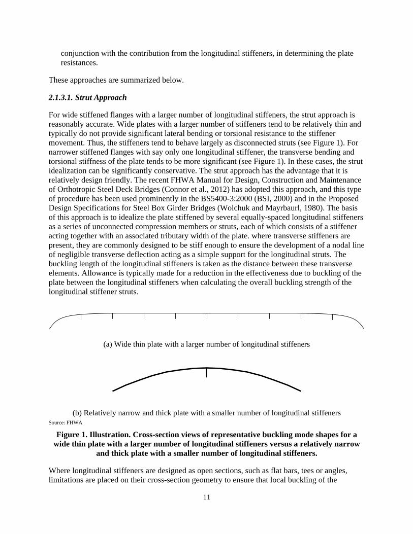
11
conjunction with the contribution from the longitudinal stiffeners, in determining the plate resistances.
These approaches are summarized below.
2.1.3.1. Strut Approach
For wide stiffened flanges with a larger number of longitudinal stiffeners, the strut approach is reasonably accurate. Wide plates with a larger number of stiffeners tend to be relatively thin and typically do not provide significant lateral bending or torsional resistance to the stiffener movement. Thus, the stiffeners tend to behave largely as disconnected struts (see Figure 1). For narrower stiffened flanges with say only one longitudinal stiffener, the transverse bending and torsional stiffness of the plate tends to be more significant (see Figure 1). In these cases, the strut idealization can be significantly conservative. The strut approach has the advantage that it is relatively design friendly. The recent FHWA Manual for Design, Construction and Maintenance of Orthotropic Steel Deck Bridges (Connor et al., 2012) has adopted this approach, and this type of procedure has been used prominently in the BS5400-3:2000 (BSI, 2000) and in the Proposed Design Specifications for Steel Box Girder Bridges (Wolchuk and Mayrbaurl, 1980). The basis of this approach is to idealize the plate stiffened by several equally-spaced longitudinal stiffeners as a series of unconnected compression members or struts, each of which consists of a stiffener acting together with an associated tributary width of the plate. where transverse stiffeners are present, they are commonly designed to be stiff enough to ensure the development of a nodal line of negligible transverse deflection acting as a simple support for the longitudinal struts. The buckling length of the longitudinal stiffeners is taken as the distance between these transverse elements. Allowance is typically made for a reduction in the effectiveness due to buckling of the plate between the longitudinal stiffeners when calculating the overall buckling strength of the longitudinal stiffener struts.
Source: FHWA
Figure 1. Illustration. Cross-section views of representative buckling mode shapes for a wide thin plate with a larger number of longitudinal stiffeners versus a relatively narrow
and thick plate with a smaller number of longitudinal stiffeners.
Where longitudinal stiffeners are designed as open sections, such as flat bars, tees or angles, limitations are placed on their cross-section geometry to ensure that local buckling of the
(a) Wide thin plate with a larger number of longitudinal stiffeners
(b) Relatively narrow and thick plate with a smaller number of longitudinal stiffeners
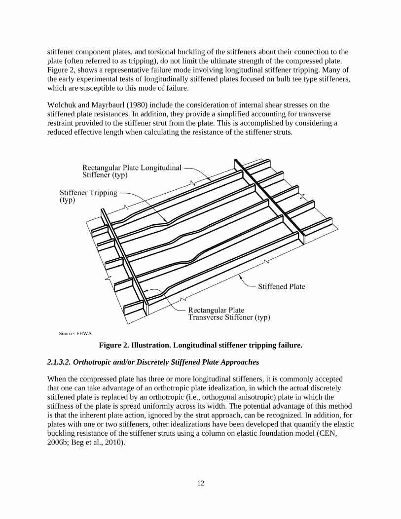
12
stiffener component plates, and torsional buckling of the stiffeners about their connection to the plate (often referred to as tripping), do not limit the ultimate strength of the compressed plate. Figure 2, shows a representative failure mode involving longitudinal stiffener tripping. Many of the early experimental tests of longitudinally stiffened plates focused on bulb tee type stiffeners, which are susceptible to this mode of failure.
Wolchuk and Mayrbaurl (1980) include the consideration of internal shear stresses on the stiffened plate resistances. In addition, they provide a simplified accounting for transverse restraint provided to the stiffener strut from the plate. This is accomplished by considering a reduced effective length when calculating the resistance of the stiffener struts.
Source: FHWA
Figure 2. Illustration. Longitudinal stiffener tripping failure.
2.1.3.2. Orthotropic and/or Discretely Stiffened Plate Approaches
When the compressed plate has three or more longitudinal stiffeners, it is commonly accepted that one can take advantage of an orthotropic plate idealization, in which the actual discretely stiffened plate is replaced by an orthotropic (i.e., orthogonal anisotropic) plate in which the stiffness of the plate is spread uniformly across its width. The potential advantage of this method is that the inherent plate action, ignored by the strut approach, can be recognized. In addition, for plates with one or two stiffeners, other idealizations have been developed that quantify the elastic buckling resistance of the stiffener struts using a column on elastic foundation model (CEN, 2006b; Beg et al., 2010).
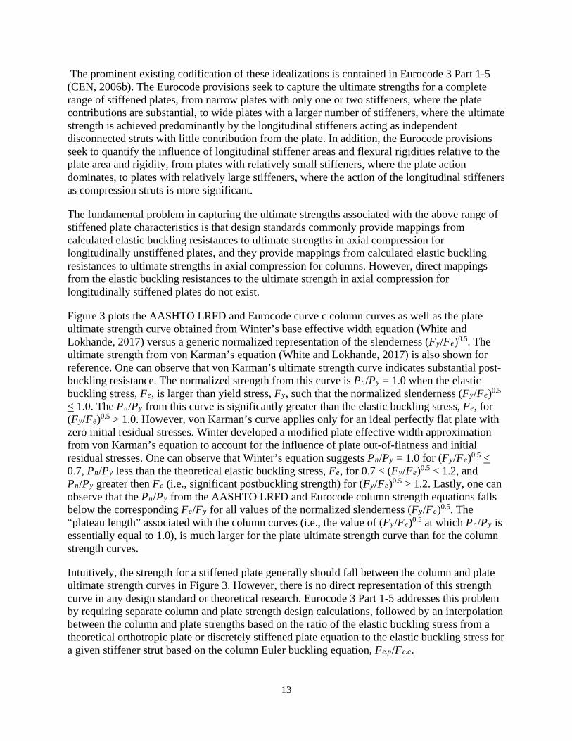
13
The prominent existing codification of these idealizations is contained in Eurocode 3 Part 1-5 (CEN, 2006b). The Eurocode provisions seek to capture the ultimate strengths for a complete range of stiffened plates, from narrow plates with only one or two stiffeners, where the plate contributions are substantial, to wide plates with a larger number of stiffeners, where the ultimate strength is achieved predominantly by the longitudinal stiffeners acting as independent disconnected struts with little contribution from the plate. In addition, the Eurocode provisions seek to quantify the influence of longitudinal stiffener areas and flexural rigidities relative to the plate area and rigidity, from plates with relatively small stiffeners, where the plate action dominates, to plates with relatively large stiffeners, where the action of the longitudinal stiffeners as compression struts is more significant.
The fundamental problem in capturing the ultimate strengths associated with the above range of stiffened plate characteristics is that design standards commonly provide mappings from calculated elastic buckling resistances to ultimate strengths in axial compression for longitudinally unstiffened plates, and they provide mappings from calculated elastic buckling resistances to ultimate strengths in axial compression for columns. However, direct mappings from the elastic buckling resistances to the ultimate strength in axial compression for longitudinally stiffened plates do not exist.
Figure 3 plots the AASHTO LRFD and Eurocode curve c column curves as well as the plate ultimate strength curve obtained from Winter’s base effective width equation (White and Lokhande, 2017) versus a generic normalized representation of the slenderness (Fy/Fe)0.5. The ultimate strength from von Karman’s equation (White and Lokhande, 2017) is also shown for reference. One can observe that von Karman’s ultimate strength curve indicates substantial post-buckling resistance. The normalized strength from this curve is Pn/Py = 1.0 when the elastic buckling stress, Fe, is larger than yield stress, Fy, such that the normalized slenderness (Fy/Fe)0.5 < 1.0. The Pn/Py from this curve is significantly greater than the elastic buckling stress, Fe, for (Fy/Fe)0.5 > 1.0. However, von Karman’s curve applies only for an ideal perfectly flat plate with zero initial residual stresses. Winter developed a modified plate effective width approximation from von Karman’s equation to account for the influence of plate out-of-flatness and initial residual stresses. One can observe that Winter’s equation suggests Pn/Py = 1.0 for (Fy/Fe)0.5 < 0.7, Pn/Py less than the theoretical elastic buckling stress, Fe, for 0.7 < (Fy/Fe)0.5 < 1.2, and Pn/Py greater then Fe (i.e., significant postbuckling strength) for (Fy/Fe)0.5 > 1.2. Lastly, one can observe that the Pn/Py from the AASHTO LRFD and Eurocode column strength equations falls below the corresponding Fe/Fy for all values of the normalized slenderness (Fy/Fe)0.5. The “plateau length” associated with the column curves (i.e., the value of (Fy/Fe)0.5 at which Pn/Py is essentially equal to 1.0), is much larger for the plate ultimate strength curve than for the column strength curves.
Intuitively, the strength for a stiffened plate generally should fall between the column and plate ultimate strength curves in Figure 3. However, there is no direct representation of this strength curve in any design standard or theoretical research. Eurocode 3 Part 1-5 addresses this problem by requiring separate column and plate strength design calculations, followed by an interpolation between the column and plate strengths based on the ratio of the elastic buckling stress from a theoretical orthotropic plate or discretely stiffened plate equation to the elastic buckling stress for a given stiffener strut based on the column Euler buckling equation, Fe.p/Fe.c.
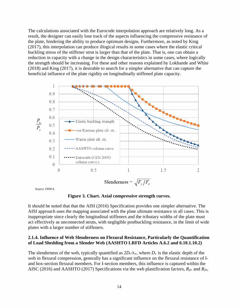
14
The calculations associated with the Eurocode interpolation approach are relatively long. As a result, the designer can easily lose track of the aspects influencing the compressive resistance of the plate, hindering the ability to produce optimum designs. Furthermore, as noted by King (2017), this interpolation can produce illogical results in some cases where the elastic critical buckling stress of the stiffener strut is larger than that of the plate. That is, one can obtain a reduction in capacity with a change in the design characteristics in some cases, where logically the strength should be increasing. For these and other reasons explained by Lokhande and White (2018) and King (2017), it is desirable to search for a simpler alternative that can capture the beneficial influence of the plate rigidity on longitudinally stiffened plate capacity.
Source: FHWA
Figure 3. Chart. Axial compressive strength curves.
It should be noted that that the AISI (2016) Specification provides one simpler alternative. The AISI approach uses the mapping associated with the plate ultimate resistance in all cases. This is inappropriate since clearly the longitudinal stiffeners and the tributary widths of the plate must act effectively as unconnected struts, with negligible postbuckling resistance, in the limit of wide plates with a larger number of stiffeners.
2.1.4. Influence of Web Slenderness on Flexural Resistance, Particularly the Quantification of Load Shedding from a Slender Web (AASHTO LRFD Articles A.6.2 and 6.10.1.10.2)
The slenderness of the web, typically quantified as 2Dc/tw, where Dc is the elastic depth of the web in flexural compression, generally has a significant influence on the flexural resistance of I- and box-section flexural members. For I-section members, this influence is captured within the AISC (2016) and AASHTO (2017) Specifications via the web plastification factors, Rpc and Rpt,
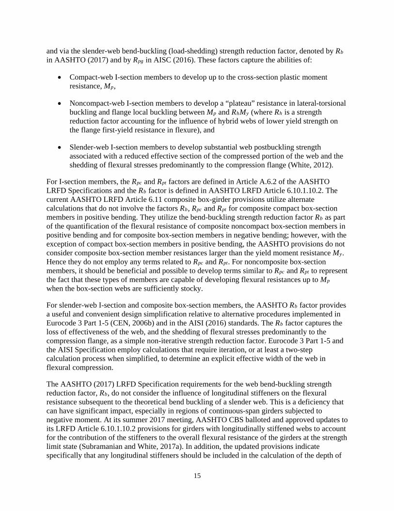
15
and via the slender-web bend-buckling (load-shedding) strength reduction factor, denoted by Rb in AASHTO (2017) and by Rpg in AISC (2016). These factors capture the abilities of:
• Compact-web I-section members to develop up to the cross-section plastic moment resistance, Mp,
• Noncompact-web I-section members to develop a “plateau” resistance in lateral-torsional buckling and flange local buckling between Mp and RhMy (where Rh is a strength reduction factor accounting for the influence of hybrid webs of lower yield strength on the flange first-yield resistance in flexure), and
• Slender-web I-section members to develop substantial web postbuckling strength associated with a reduced effective section of the compressed portion of the web and the shedding of flexural stresses predominantly to the compression flange (White, 2012).
For I-section members, the Rpc and Rpt factors are defined in Article A.6.2 of the AASHTO LRFD Specifications and the Rb factor is defined in AASHTO LRFD Article 6.10.1.10.2. The current AASHTO LRFD Article 6.11 composite box-girder provisions utilize alternate calculations that do not involve the factors Rb, Rpc and Rpt for composite compact box-section members in positive bending. They utilize the bend-buckling strength reduction factor Rb as part of the quantification of the flexural resistance of composite noncompact box-section members in positive bending and for composite box-section members in negative bending; however, with the exception of compact box-section members in positive bending, the AASHTO provisions do not consider composite box-section member resistances larger than the yield moment resistance My. Hence they do not employ any terms related to Rpc and Rpt. For noncomposite box-section members, it should be beneficial and possible to develop terms similar to Rpc and Rpt to represent the fact that these types of members are capable of developing flexural resistances up to Mp when the box-section webs are sufficiently stocky.
For slender-web I-section and composite box-section members, the AASHTO Rb factor provides a useful and convenient design simplification relative to alternative procedures implemented in Eurocode 3 Part 1-5 (CEN, 2006b) and in the AISI (2016) standards. The Rb factor captures the loss of effectiveness of the web, and the shedding of flexural stresses predominantly to the compression flange, as a simple non-iterative strength reduction factor. Eurocode 3 Part 1-5 and the AISI Specification employ calculations that require iteration, or at least a two-step calculation process when simplified, to determine an explicit effective width of the web in flexural compression.
The AASHTO (2017) LRFD Specification requirements for the web bend-buckling strength reduction factor, Rb, do not consider the influence of longitudinal stiffeners on the flexural resistance subsequent to the theoretical bend buckling of a slender web. This is a deficiency that can have significant impact, especially in regions of continuous-span girders subjected to negative moment. At its summer 2017 meeting, AASHTO CBS balloted and approved updates to its LRFD Article 6.10.1.10.2 provisions for girders with longitudinally stiffened webs to account for the contribution of the stiffeners to the overall flexural resistance of the girders at the strength limit state (Subramanian and White, 2017a). In addition, the updated provisions indicate specifically that any longitudinal stiffeners should be included in the calculation of the depth of

16
the web in compression and the yield moment, as well as other section properties pertaining to the major-axis of bending, such as the elastic section moduli Sxc and Sxt utilized in the calculation of the flexural stresses. Related 2017 updates to the AASHTO LRFD provisions have increased a limit on the transverse stiffener spacing in longitudinally stiffened webs from 1.5D to 2.0D, where D is the total depth of the web, and have increased the maximum limit on a curvature parameter pertaining to the design of web longitudinal stiffeners, termed Z, from 10 to 12 in Articles 6.10.9.1, 6.10.11.1.1 and 6.10.11.3.3.
The above advances in the handling of web slenderness effects, including longitudinal web stiffening, should be considered in the development of improved provisions for noncomposite steel box-section members.
2.1.5. Web Shear Strength in Box-Section Members (AASHTO LRFD Articles 6.10.9 and 6.11.9)
The AASHTO LRFD Specifications address the web shear strength of I-section and composite box-section members in their Articles 6.10.9 and 6.11.9. White and Barker (2008) and White et al. (2008) argue that the Basler tension field action model implemented in these provisions provides the best combination of accuracy and simplicity of existing shear strength models for transversely stiffened webs. In addition, White et al. (2008) show that moment-shear interaction effects can be neglected when performing shear strength calculations based on this model, and flexural strength calculations based on the AASHTO LRFD provisions, as long as a reduced shear strength is determined by a variation on the calculations referred to as the “true Basler” tension field action model for members with relatively small flanges. Subramanian and White (2017b) have recently confirmed the accuracy of the Basler and true Basler tension field action models for calculation of the shear resistance of longitudinally stiffened webs, including the lack of need for consideration of moment-shear strength interaction effects.
Regarding the shear strength of unstiffened webs, Daley et al. (2016) have shown that the shear buckling model employed in the AASHTO (2017) and prior AISC (2010) Specification provisions tends to give substantially conservative estimates of the true shear strength of unstiffened webs. Based on this research, the AISC 360-16 (AISC, 2016) Specification has adopted new provisions that recognize the ability of both stiffened and unstiffened webs to develop significant postbuckling resistance in shear. These provisions are based on Höglund’s (1997) Rotated Stress Field Theory (RSFT). For unstiffened webs that were subject to the inelastic shear buckling limit state in previous Specifications, the calculations are exactly the same as in AISC (2010). However, for webs with larger slenderness values that were subject to the elastic shear buckling limit state in previous Specifications, the shear resistance is substantially increased. The new AISC (2016) Section G2.1 provisions, based on RSFT, characterize the shear buckling plus postbuckling strength in this range simply by utilizing the previous inelastic shear buckling equation for all slenderness values. Jha (2016) explains the tie of this form of the equations to Höglund’s prior developments.
The Eurocode 3 Part 2 (CEN, 2006a) provisions point to the corresponding Part 1-5 provisions (CEN, 2006b) for related shear strength calculations, and also specify a limit on the slenderness of web plates to avoid excessive “breathing” that might result in fatigue at or adjacent to web-to-

17
flange connections. The web breathing requirements are related to limits on service load stresses in the plates relative to the theoretical elastic buckling level under combined shear and flexure.
The above state-of-the-art in quantifying the shear resistance of I- and box-section member webs should be considered in the development of improved provisions for noncomposite steel box-section members.
2.1.6. Force Interaction (AASHTO LRFD Articles 6.8 and 6.9)
Articles 6.8 and 6.9 of the AASHTO LRFD Specifications address the interaction between axial tension or axial compression and biaxial bending. As noted in Sections 2.1.1 through 2.1.3, with the exception of Article 6.11.8, the AASHTO Specifications do not address the influence of internal torsion on the design resistance of box-section members. Furthermore, it is important to note that the bilinear beam-column strength interaction equations provided in Articles 6.8 and 6.9 were developed predominantly based on the consideration of in-plane major- and minor-axis bending and axial compression of doubly symmetric rolled I-section members (White, 2012). Their applicability to the interaction of various internal force effects on the design resistance may be suspect for certain cases, such as large noncomposite box-section members containing plates with intermediate longitudinal and/or transverse stiffeners. A key consideration of this project is the proper handling of axial tension or compression combined with biaxial bending and shear due to bending and internal torsion, for general noncomposite box-section members.
2.1.7. Other General Considerations
It is necessary to address various other general considerations when considering the design of a broad range of steel box-section members in highway bridge construction. A few of these considerations are discussed below.
One area where the limits of basic beam theory must be addressed is the consideration of shear lag associated with the flexural response of box-section members having wide, thin stiffened or unstiffened flange plates. Shear lag arises because the in-plane shear deformations of a flange cause those parts most remote from the webs to develop smaller longitudinal stresses than the parts in the vicinity of the web. Shear lag effects tend to be the largest in members with flanges that are relatively wide compared to the member length. In addition, the use of longitudinal stiffeners across the flange width results in the nonuniformity of the flange flexural stresses becoming even more pronounced.
Moffatt and Dowling (1975 and 1976) conducted a systematic study of the factors influencing shear lag in box-girder flanges. Their work forms the basis for flange effective width recommendations in the Manual for Design, Construction, and Maintenance of Orthotropic Steel Deck Bridges (Connor et al., 2012), in the Proposed Design Specifications for Steel Box Girder Bridges (Wolchuk and Mayrbaurl, 1980) and in the British Code of Practice for Design of Steel, Bridges, BS5400 Part 3 (BSI, 2000). It should be noted that the reduction in flange effective widths due to shear lag is generally separate and distinct from the reduction in flange effective widths due to plate local buckling.
The nonuniform distribution of in-plane stresses in a box-section member flange is of interest from the point of view of the structural stability. The pattern of the stresses as influenced by

18
shear lag can increase or decrease the average stress, causing earlier buckling of the flange compared with the uniformly compressed case (depending on the degree of stiffening of the plate). On the other hand, the concentration of the longitudinal normal stresses near the edges of the plate encourages the earlier onset of yield at the edges compared to uniform stressing across the flange width. The interaction of these two effects is complex, and in fact, is complicated further by the extent to which the stiffeners and plate panels can redistribute load. Nevertheless, tests have shown that for most practical cases, shear lag can be ignored in calculating the ultimate compressive strength of stiffened or unstiffened flanges (Dowling et al. 1977; Friez and Dowling, 1979). In addition, this conclusion has been supported by various numerical test simulation studies cited in Article C4.6.2.6.4 of AASHTO (2017). Therefore, a flange usually can be considered to be loaded uniformly across its width at the ultimate limit state. Only in the case of flanges with particularly large width-to-length ratios, or particularly slender edge panels or stiffeners, is it necessary to consider the impact of shear lag on flange stability in greater detail (Ziemian, 2010).
AASHTO LRFD (AASHTO, 2017) Article 4.6.2.6.4, Orthotropic Steel Decks, adopts the above philosophy for consideration of ultimate strength, by not requiring any reduction in the effective flange width due to shear lag except for extreme cases where the span length of the member is less than five times the spacing between the web plates. In these extreme cases, the flange effective width is taken equal to 5L, where L is defined as the span length. These recommendations are roughly parallel to the effective width provisions in AASHTO (2017) Article 6.11.1.1, which are based on the work by Goldberg and Leve (1957). Article 6.11.1.1 uses this same rule, but with the term effective span length. This article defines the effective span as the actual span length for simple spans, and as the different lengths between the dead load inflection points or between a point of inflection and a simply-supported end for continuous spans. Similar definitions of effective span are common within shear lag rules of various standards. For cantilevers, the effective span is commonly taken as two times the actual span length.
Regarding shear lag effects under elastic loading conditions associated with service and fatigue limit states, Article 4.6.2.6.4 indicates, “for service and fatigue limit states in regions of high shear, a special investigation into shear lag should be done.” Regarding these considerations, Connor et al. (2012) state, “For Service and Fatigue limit states in regions of high shear the effective deck width can be determined by refined analysis or other accepted approximate methods. Additionally, consideration of effective width of the deck plate can be avoided by application of refined analysis methods.” Connor et al. (2012) specify a chart of effective width versus effective span length for different conditions, adopted from Wolchuk and Mayrbaurl (1980) and based on the original work by Moffatt and Dowling (1975 and 1976). This chart appeared in Article 4.6.2.6.4 of former versions of the AASHTO LRFD Specifications; however, it no longer appears in this article in AASHTO (2017).
In this research, the above rules, and other findings pertinent to shear lag in noncomposite box-section member flanges, should be scrutinized and recommendations should be provided in the spirit of the overall project goals of consistency, accuracy, generality and ease of design application.

19
One area of significant complexity in the design of large box-section members is the provision of diaphragms to transfer loads at supports, and to restrain the tendency of the box-section to distort. It is well established that internal cross-frames and/or diaphragms are essential to limit the distortional warping and plate transverse bending stresses in box-section members subjected to significant applied torsional loads. AASHTO LRFD Article 6.7.4.3 and its commentary give criteria for the provision of internal cross-frames and/or diaphragms to limit cross-section distortion in box-section members. Furthermore, Article 6.11.1.1 requires that for certain box-sections, transverse bending stresses due to cross-section distortion be limited to 20 ksi at the strength limit state via the provision of internal cross-frames or diaphragms. In addition, for these sections, Article C6.7.4.3 recommends that longitudinal warping stresses due to cross-section distortion be limited to approximately 10 % of the longitudinal stresses due to major-axis bending at the strength limit state.
Regarding the calculation of local plate bending stresses due to box-section distortion, the Beam on Elastic Foundation (BEF) analogy developed by Wright and Abdel-Samad (1968) has long been the primary calculation approach referenced within US practice. The solution by these authors relies centrally on the selection of major parameters via charts. Haaijer (1981) developed a simple modeling technique that implements these concepts in a local analysis of the cross-section using a two-dimensional frame element idealization. Yoo et al. (2015) presented a detailed development and use of computational tools for analysis for box-section distortional stresses. Their approach also employs a two-dimensional frame element idealization for the local analysis. Fan and Helwig (2002) and Helwig et al. (2007) have presented comprehensive developments of closed-form equations for estimation of internal cross-frame forces associated with the restraint of cross-section distortion in bridge tub girders. These authors point to Dabrowski (1968) for the specific calculation of box-girder distortional warping and distortional plate bending stresses. Appendix B of BS5400-3:2000 (BSI, 2000), the British Code of Practice for Design of Steel Bridges, provides detailed closed-form equations for calculation of plate distortional stresses in trapezoidal box-section members. These and the AASHTO LRFD rules should be scrutinized to ensure the greatest simplicity of calculation as well as general applicability in the proposed research.
Lastly, the impact of member curvature on the capacity of stiffened and unstiffened box-section plates needs to be addressed. This impact is likely to be small in many situations, i.e., on the order of the impact of initial imperfections assumed in the development of plate capacity equations. Specifically, the influence of the vertical curve of an arch rib on the strength of its flange plates should be considered.
2.2. TASKS 2 AND 3 - DEVELOPMENT AND EVALUATION OF POTENTIAL RESISTANCE FORMUATIONS, AND DEMONSTRATION OF ACCURACY AND RELIABILITY OF PROPOSED PROVISIONS
This section gives a broad overview of the advancements in the recommended AASHTO LRFD Specifications achieved in this research, addressing the above considerations. More specific and detailed discussions of the various provisions are provided in Chapter 3.

20
2.2.1. Longitudinally Unstiffened Box-Section Members
2.2.1.1. Plate Ultimate Strengths
As noted in Section 2.1.2, the 8th Edition of the AASHTO LRFD Specifications (AASHTO, 2017) has adopted a version of the unified effective area approach to quantify the ultimate resistance of longitudinally unstiffened plates subject to uniform axial compression. The form of these recommended equations parallels that of the equations implemented in AISC 360-16 (AISC, 2016) with one important difference. Research ranging back to the early work by Dowling and others and reflected in BS 5400-3:2000 (BSI, 2000) indicates that for members composed of general welded plate assemblies, the plate ultimate (local buckling plus postbuckling) resistances are lower than that indicated by Winter’s classical effective width equation (Winter, 1970). Johansson and Velijkovic (2009), Schillo (2017) and Schillo and Taras (2018) have also found Winter’s effective width equation to be optimistic for unstiffened plates in welded box-section members.
As such, a simple downward shift of Winter’s classical curve, in its normalized form, by 0.075 is recommended in this research to provide a better fit to the experimental and analytical data for welded construction. Figure 4 compares the classical Winter’s curve and the recommended modified form to the experimental data for box-section stub columns collected and generated by Schillo (2017). The ordinate ρ is the ratio of the plate strength to the gross yield load of the plate, and the abscissa is the square root of the ratio of the actual yield strength to the theoretical elastic buckling strength, given the physical dimensions of the columns. The modified curve is very similar to the multi-part curve specified in BS 5400-3:2000 (BSI, 2000). Additional results from finite element simulation studies are provided by Schillo (2017) and by Lokhande and White (2018) that support this reduction in the result from the classical Winter’s curve.
Table 1 presents the statistical data for the professional factor, Ptest/Pn, based on the experimental data from Schillo (2017). The mean value of Ptest/Pn for all 127 tests shown in Figure 4 is 1.056 with a coefficient of variation of 0.072. The middle range of the slenderness from 1.0 to 1.5 has the smallest mean Ptest/Pn (1.020) with a coefficient of variation of 0.074. Schillo (2017) and Schillo and Taras (2018) present an alternative exponential form for the ρ factor that fits the mean of the test data somewhat better throughout the ranges of slenderness considered in Figure 4. However, the simple shift in the ordinate of Winter’s classical curve is recommended for the AASHTO LRFD Specifications because of the familiarity of Winter’s classical equation, and was balloted and approved by the AASHTO CBS at their summer 2017 meeting.
The above modification to Winter’s equation gives a corresponding nonslender b/t limit of
1.09 /rf yE Fλ = (1)
That is, for plate width-to-thickness ratios, b/t, less than that given by the above equation, plate local buckling effects are taken to be negligible. For Fy = 50 ksi, Equation 1 gives λrf = 26.3.

21
Source: FHWA
Figure 4. Chart. Comparison of experimental test resistances from welded stub column test data collected and generated by Schillo (2017) to Winter’s classical effective width equation
and to the modified form of this equation recommended in this research.
Table 1. Statistical data for professional factor, Ptest/Pn, modified Winter’s equation versus slenderness, based on the experimental data from Schillo (2017).
y elF / F MEAN COV MAX MIN N
0.0 to 0.5 1.100 0.039 1.140 1.050 4 0.5 to 1.0 1.071 0.075 1.220 0.920 74 1.0 to 1.5 1.020 0.074 1.148 0.863 33 1.5 to 2.5 1.054 0.063 1.173 0.982 15 All data 1.056 0.072 1.220 0.863 127
An existing variation on Winter’s classical curve defined in the AISC 360-16 Specification (AISC, 2016) and (AASHTO, 2015) is recommended to characterize the effective width of slender elements in square and rectangular hot-formed HSS. This form is also recommended for flanges and webs of non-welded built-up box-sections. White and Lokhande (2017) provide a detailed explanation of the history behind this and other variations on Winter’s effective width equation. The recommended nonslender b/t limit for plate elements in the above types of members is
1.40 /rf yE Fλ = (2)
which indicates that local buckling effects may be neglected for the above sections in all cases for b/t < 33.7, assuming Fy = 50 ksi. The reader is referred to the subsequent presentations in Chapter 3, Sections 3.1.1 and 3.1.2 for a detailed presentation of the plate effective width equations and the definitions of the plate widths, b, employed with these equations.
0
0.2
0.4
0.6
0.8
1
1.2
0 0.5 1 1.5 2 2.5
ρ
Winter's curve
Modified Winter's curve

22
The base form of Winter’s equation from AISI (2016) is recommended for the characterization of cold-formed square and rectangular HSS. This form gives a nonslender b/t limit for plate elements of
1.28 /rf yE Fλ = (3)
which indicates that local buckling effects may be neglected for b/t < 30.8, assuming Fy = 50 ksi.
It should be noted that the difference between the above two forms of Winter’s equation becomes rather minute as the b/t values become larger relative to the above nonslender plate limits. However, clearly there are measurable differences between the above nonslender plate limits, and there are measureable differences between the plate ultimate strengths for slender b/t values in the vicinity of these limits.
In addition, as discussed subsequently, the ultimate resistance of plate panels in longitudinally stiffened box-section members is generally somewhat larger, due to the restraint offered by adjacent panels within the plane of the plate. The above equations are based on the assumption of negligible lateral restraint, within the plane of the plate, along the plate longitudinal edges. Adjacent plate panels within longitudinally stiffened plates tend to provide significant lateral restraint to each other along the panel edges at the longitudinal stiffeners. That is, the adjacent panels tend to force a condition where the panel longitudinal edges stay relatively straight, within the plane of the plate, in the failure mode of the panels.
2.2.1.2. Longitudinally Unstiffened Box-Section Member Resistances in Axial Compression
Based on the unified effective width method (Peköz, 1987; AISI, 2016; AISC 2016), the axial compressive resistance of members composed of longitudinally unstiffened plate elements is determined as follows:
n cr effP F A= (4)
where:
Fcr = the column buckling stress calculated based on the gross cross-section properties. Aeff = the member cross-section effective area calculated at a stress level equal to Fcr.
The consideration of longitudinally stiffened plates is addressed subsequently. The effective area, Aeff, is obtained by multiplying the plate effective widths, determined using the appropriate effective width equation, by their thickness, and summing these plate effective areas with other gross areas such as the corner areas of welded box sections. Lokhande and White (2018) review the logic of and the rationale for this calculation.
The overall effectiveness of the unified effective width method for calculation of the axial compressive resistances of members composed of slender plate elements is well established (Peköz, 1987; Ziemian, 2010) and its application to rolled and built-up longitudinally unstiffened steel members is discussed in detail by Geschwindner and Troemner (2016). The following section discusses the use of the recommended unified effective width equations to address plate
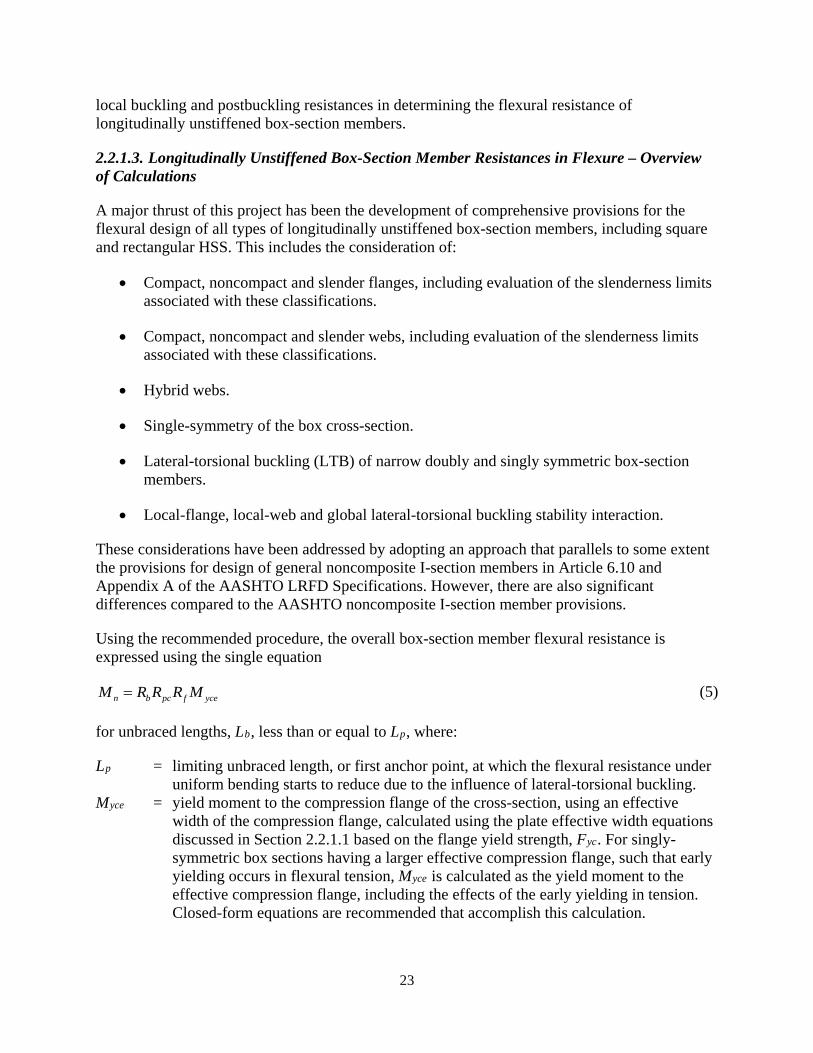
23
local buckling and postbuckling resistances in determining the flexural resistance of longitudinally unstiffened box-section members.
2.2.1.3. Longitudinally Unstiffened Box-Section Member Resistances in Flexure – Overview of Calculations
A major thrust of this project has been the development of comprehensive provisions for the flexural design of all types of longitudinally unstiffened box-section members, including square and rectangular HSS. This includes the consideration of:
• Compact, noncompact and slender flanges, including evaluation of the slenderness limits associated with these classifications.
• Compact, noncompact and slender webs, including evaluation of the slenderness limits associated with these classifications.
• Hybrid webs.
• Single-symmetry of the box cross-section.
• Lateral-torsional buckling (LTB) of narrow doubly and singly symmetric box-section members.
• Local-flange, local-web and global lateral-torsional buckling stability interaction.
These considerations have been addressed by adopting an approach that parallels to some extent the provisions for design of general noncomposite I-section members in Article 6.10 and Appendix A of the AASHTO LRFD Specifications. However, there are also significant differences compared to the AASHTO noncomposite I-section member provisions.
Using the recommended procedure, the overall box-section member flexural resistance is expressed using the single equation
n b pc f yceM R R R M= (5)
for unbraced lengths, Lb, less than or equal to Lp, where:
Lp = limiting unbraced length, or first anchor point, at which the flexural resistance under uniform bending starts to reduce due to the influence of lateral-torsional buckling.
Myce = yield moment to the compression flange of the cross-section, using an effective width of the compression flange, calculated using the plate effective width equations discussed in Section 2.2.1.1 based on the flange yield strength, Fyc. For singly-symmetric box sections having a larger effective compression flange, such that early yielding occurs in flexural tension, Myce is calculated as the yield moment to the effective compression flange, including the effects of the early yielding in tension. Closed-form equations are recommended that accomplish this calculation.

24
Rb = web bend buckling (load shedding) strength reduction factor, adapted from the I-section member provisions of AASHTO Article 6.10.1.10.2 for slender-web sections, and taken equal to 1.0 for compact- and noncompact-web sections.
Rpc = web plastification factor, which varies from the shape factor for the effective cross-section, Mpe/Mye, for a compact-web section to the hybrid web factor, Rh, for a slender-web section; the effective plastic moment, Mpe, is calculated where needed based on an idealization of the fully-plastic cross-section using the effective width of the compression flange, calculated using the equations discussed in Section 2.2.1.1. This factor, and the above web load shedding factor, are evaluated as functions of the effective depth of the web in compression associated with the calculation of Myce.
Rf = compression flange slenderness factor, which varies from 1.0 for a compact flange to 0.85 for a slender flange. This factor accounts for the limited ability of a thinner compression flange to develop large inelastic strains without a reduction in the flange force contribution, when the webs are compact or noncompact, as well as the limited ability of a thinner compression flange to accept stresses shed due to the bend buckling of slender webs.
For larger unbraced lengths, Lb greater than Lp, the flexural resistance is expressed for all types of box-section members using the single equation
( ) b ppc f yce yr xcepc f ycen b b b pc f yce
r p
L LR R M F SR R MM C R R R R M
L L−
−−= ≤ − (6)
where:
Cb = moment gradient factor, calculated using the same procedures as discussed for I-section members in AASHTO LRFD Article 6.10.8.
Fyr = compression flange flexural stress defining the second anchor point for the LTB strength reduction equation at a large unbraced length, Lr; taken equal to 0.5Fyc.
Sxce = elastic section modulus to the compression flange. Lr = large unbraced length defining the second anchor point for the LTB strength
reduction equation.
The length limits Lp and Lr are derived using the theoretical equations for elastic LTB, similar to the development of the equations for these terms in the case of I-section members. The length Lp is the unbraced length at which the elastic LTB critical moment is equal to 15 times the plastic moment Mp, as in the AISC 360-16 Section F7 provisions, but with Mp taken equal to 1.3 Myce. This magnitude of the elastic LTB critical moment defines the limiting condition at which the “plateau” resistance, Equation 5, can just be achieved. The length Lr is defined as 0.3 of the length corresponding to theoretical elastic LTB at a compression flange stress of Fyr. The Equation 6 resistance curve gives results comparable to the applicable CEN (2005) resistance curve for LTB of box-section members (Lokhande and White, 2018).
In Lokhande and White (2018), the elastic LTB equations for a general singly-symmetric cross-section member are presented. These equations were employed initially in the development of the above flexural resistance provisions. However, for all box-section members within the
25
practical extreme limits permitted by the recommended Specifications, the simpler elastic LTB equations based on the assumption of a doubly symmetric box cross-section give predictions that are always within one percent of the exact elastic LTB equations. It should be noted that the elastic LTB equations appear solely in the derivation of the Lp and Lr limits within the recommended provisions. The lengths required for elastic LTB of even the most extreme box-section members are so large that members having these lengths are not possible. Therefore, only the simpler doubly symmetric box-section LTB equations are employed for the calculation of Lp and Lr within the recommended provisions. The resulting equations for Lp and Lr are
0.10p yyce
JAL ErM
= (7)
and
0.60 12r y pyr xce
JAL Er LF S
= = (8)
where:
ry = radius of gyration of the gross box cross-section about its minor principal axis. J = St. Venant torsional constant of the gross box cross-section. A = gross cross-sectional area of the box cross-section.
The compact-flange limit in the recommended provisions is taken as the nonslender plate limit for uniform axial compression, i.e., the slenderness limit at which the ρ factor from the modified or non-modified Winter’s curve in Section 2.2.1.1 becomes less than 1.0. In terms of a b/t limit on the compression flange, this limit is given by Equation 1 for welded box-sections, Equation 3 for rectangular cold-formed HSS, and Equation 2 for non-welded built-up box-sections and rectangular hot-formed HSS. The limit given by Equation 1 is comparable to the compact flange limit specified for all HSS and box sections in AISC (2016), and it is comparable to the Class 1 flange limit in Eurocode 3, Part 1-1 (CEN, 2005), which is intended to ensure that the section can form a plastic hinge with a rotation capacity sufficient for plastic analysis. The limit given by Equation 3 is comparable to the Class 2 flange limit in Eurocode 3, which is intended to ensure that the plastic moment of the cross-section can be developed. The limit given by Equation 2 is slightly larger than the Eurocode 3 Class 2 flange limit. Equations 1 through 3 effectively recognize the different conditions associated with each of the above section types.
It is important to note that the different forms of Winter’s plate effective width equations are commonly based on simply-supported edge conditions, i.e., no rotational restraint from the adjacent plates. Clearly, if one has a box-section member with a noncompact or slender flange in flexure and say a compact web, some rotational restraint at the longitudinal edges of the flange might be anticipated from the compact web. This helps explain, conceptually, along with the influence of the Rf factor, why and how the Mpe-based model works to characterize the strength of a member with a noncompact or slender flange and a compact web.
26
The noncompact flange slenderness limit in flexure, which in the recommended provisions has the function only of defining the slenderness beyond which Rf is reduced to a constant value of 0.85, is taken as 1.56λpf.
The compact-web slenderness limit in the recommended provisions is somewhat larger than the corresponding value for doubly symmetric box-sections in AISC (2016), and tends to be slightly larger than the Class 2 limit for noncomposite box-sections specified in Eurocode 3 Part 1-1 (CEN, 2005). The recommended equation for this limit, which is used with the web effective slenderness 2Dce/tw for the classification of box-section webs, is
3.1 /cepw yc rw
cpe
D E FD
λ = ≤ λ (9)
where Dce is the depth of web in compression corresponding to first nominal yielding of the effective compression flange, and Dcpe is the depth of web in compression at the plastic moment, determined using the effective box cross-section based on the effective width of the compression flange.
The noncompact web slenderness limit in the recommended provisions, which is the value of 2Dce/tw beyond which Rpc is a constant value equal to Rh, and beyond which Rb reduces below 1.0, is taken as
4.6 /rw ycE Fλ = (10)
This limit assumes simply-supported boundary conditions at the web-flange juncture, and is the same as the noncompact web limit for I-sections in cases where the area of the I-section flanges is small relative to the web area in the provisions approved for the 2020 9th Edition of the LRFD Specifications by AASHTO CBS in 2017. These provisions are based on the research summarized in Subramanian and White (2017a and b). This limit is slightly larger than the Class 3 limit for noncomposite box-sections specified in CEN (2005).
2.2.1.4. Evaluation of the Recommended Method, Longitudinally Unstiffened Box-Section Members in Flexure
At the present time (2019), there are no experimental data for the flexural resistance of longitudinally unstiffened welded box-section members in the literature. Hence, the performance of the above recommended method is evaluated for these types of members via a parametric study performed using finite element test simulations. Details of the member designs and the finite element test simulation procedures are provided in Lokhande and White (2018). All of the members in the parametric study are torsionally and flexurally simply-supported and are subjected to uniform bending. Table 2 provides a summary of the members considered in this study:
• The first column of the table lists the cross-section number. A total of 46 different welded box sections are considered.
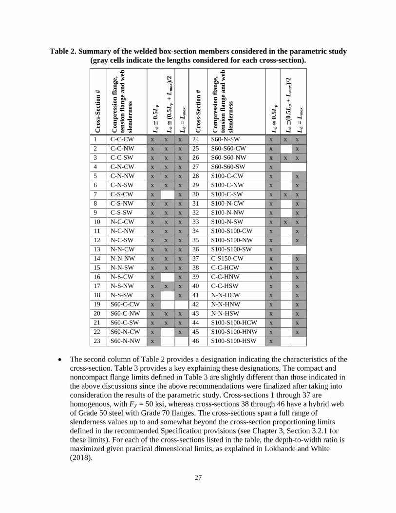
27
Table 2. Summary of the welded box-section members considered in the parametric study (gray cells indicate the lengths considered for each cross-section).
Cro
ss-S
ectio
n #
Com
pres
sion
flang
e,
tens
ion
flang
e an
d w
eb
slen
dern
ess
Lb ≅
0.5
Lp
Lb ≅
(0.5
Lp +
Lm
ax)/2
Lb =
Lm
ax
Cro
ss-S
ectio
n #
Com
pres
sion
flang
e,
tens
ion
flang
e an
d w
eb
slen
dern
ess
Lb ≅
0.5
Lp
Lb ≅
(0.5
Lp +
Lm
ax)/2
Lb =
Lm
ax
1 C-C-CW x x x 24 S60-N-SW x x x 2 C-C-NW x x x 25 S60-S60-CW x x 3 C-C-SW x x x 26 S60-S60-NW x x x 4 C-N-CW x x x 27 S60-S60-SW x 5 C-N-NW x x x 28 S100-C-CW x x 6 C-N-SW x x x 29 S100-C-NW x x 7 C-S-CW x x 30 S100-C-SW x x x 8 C-S-NW x x x 31 S100-N-CW x x 9 C-S-SW x x x 32 S100-N-NW x x 10 N-C-CW x x x 33 S100-N-SW x x x 11 N-C-NW x x x 34 S100-S100-CW x x 12 N-C-SW x x x 35 S100-S100-NW x x 13 N-N-CW x x x 36 S100-S100-SW x 14 N-N-NW x x x 37 C-S150-CW x x 15 N-N-SW x x x 38 C-C-HCW x x 16 N-S-CW x x 39 C-C-HNW x x 17 N-S-NW x x x 40 C-C-HSW x x 18 N-S-SW x x 41 N-N-HCW x x 19 S60-C-CW x 42 N-N-HNW x x 20 S60-C-NW x x x 43 N-N-HSW x x 21 S60-C-SW x x x 44 S100-S100-HCW x x 22 S60-N-CW x x 45 S100-S100-HNW x x 23 S60-N-NW x 46 S100-S100-HSW x
• The second column of Table 2 provides a designation indicating the characteristics of the cross-section. Table 3 provides a key explaining these designations. The compact and noncompact flange limits defined in Table 3 are slightly different than those indicated in the above discussions since the above recommendations were finalized after taking into consideration the results of the parametric study. Cross-sections 1 through 37 are homogenous, with Fy = 50 ksi, whereas cross-sections 38 through 46 have a hybrid web of Grade 50 steel with Grade 70 flanges. The cross-sections span a full range of slenderness values up to and somewhat beyond the cross-section proportioning limits defined in the recommended Specification provisions (see Chapter 3, Section 3.2.1 for these limits). For each of the cross-sections listed in the table, the depth-to-width ratio is maximized given practical dimensional limits, as explained in Lokhande and White (2018).
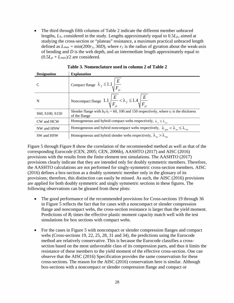
28
• The third through fifth columns of Table 2 indicate the different member unbraced lengths, Lb, considered in the study. Lengths approximately equal to 0.5Lp, aimed at studying the cross-section or “plateau” resistance, a maximum practical unbraced length defined as Lmax = min(200ry, 30D), where ry is the radius of gyration about the weak-axis of bending and D is the web depth, and an intermediate length approximately equal to (0.5Lp + Lmax)/2 are considered.
Table 3. Nomenclature used in column 2 of Table 2 Designation Explanation
C Compact flange 1.1fyc
EF
λ ≤
N Noncompact flange 1.1 1.4fyc yc
E EF F
< λ ≤
S60, S100, S150 Slender flange with bfi/tf = 60, 100 and 150 respectively, where tf is the thickness of the flange
CW and HCW Homogeneous and hybrid compact webs respectively, w pwλ ≤ λ
NW and HNW Homogeneous and hybrid noncompact webs respectively, pw w rwλ < λ ≤ λ
SW and HSW Homogeneous and hybrid slender webs respectively, w rwλ > λ
Figure 5 through Figure 8 show the correlation of the recommended method as well as that of the corresponding Eurocode (CEN, 2005; CEN, 2006b), AASHTO (2017) and AISC (2016) provisions with the results from the finite element test simulations. The AASHTO (2017) provisions clearly indicate that they are intended only for doubly symmetric members. Therefore, the AASHTO calculations are not performed for singly-symmetric cross-section members. AISC (2016) defines a box-section as a doubly symmetric member only in the glossary of its provisions; therefore, this distinction can easily be missed. As such, the AISC (2016) provisions are applied for both doubly symmetric and singly symmetric sections in these figures. The following observations can be gleaned from these plots:
• The good performance of the recommended provisions for Cross-sections 19 through 36 in Figure 5 reflects the fact that for cases with a noncompact or slender compression flange and noncompact webs, the cross-section resistance is larger than the yield moment. Predictions of Rf times the effective plastic moment capacity match well with the test simulations for box sections with compact webs.
• For the cases in Figure 5 with noncompact or slender compression flanges and compact webs (Cross-sections 19, 22, 25, 28, 31 and 34), the predictions using the Eurocode method are relatively conservative. This is because the Eurocode classifies a cross-section based on the most unfavorable class of its compression parts, and thus it limits the resistance of these members to the yield moment of the effective cross-section. One can observe that the AISC (2016) Specification provides the same conservatism for these cross-sections. The reason for the AISC (2016) conservatism here is similar. Although box-sections with a noncompact or slender compression flange and compact or

29
noncompact webs are more unusual, they may be encountered when considering biaxial bending, as discussed previously in Section 2.1.1.
Source: FHWA
Figure 5. Chart. Comparison of nominal strength estimates to strengths from test simulation for homogeneous welded box-section members with Lb ≅ 0.5Lp.
Source: FHWA
Figure 6. Chart. Comparison of nominal strength estimates to strengths from test simulation for homogeneous welded box-section members with Lb ≅ (0.5Lp + Lmax)/2.

30
Source: FHWA
Figure 7. Chart. Comparison of nominal strength estimates to strengths from test simulation for homogeneous welded box-section members with Lb = Lmax.
Source: FHWA
Figure 8. Chart. Comparison of nominal strength estimates from recommended method to strengths from test simulation for hybrid box-section members with Lb ≅ 0.5Lp and Lmax.
• The recommended method gives good correlation with the test simulation results for extreme singly-symmetric cross-sections exhibiting early tension yielding (Cross-sections 7, 8, 9 and 37 in Figure 5). The Eurocode method gives a significantly conservative estimate of the test simulation results for Cross-section 9, since it limits the resistance to the first yield in tension for Class 4 box-section members. With the exception of the other limitations mentioned in these discussions, the AISC provisions perform reasonably well for the singly symmetric cross-section members, although they are intended only for

31
doubly symmetric sections. This is because the elastic section modulus, where it shows up in the AISC equations, is taken to the compression flange. Also, as noted above, Lokhande and White (2018) determined that the simpler doubly symmetric section elastic LTB equations could be employed as the base for the calculation of Lp and Lr for all box-section members, within the specified proportioning limits for the recommended procedure, without significantly impacting the LTB results.
• For the members with a compact compression flange and compact or noncompact webs in Figure 5, the test simulation cross-section resistance is larger than the yield moment and is as high as the plastic moment. Thus for Cross-sections 1, 2, 13 and 14 in Figure 5, the strength predicted by the AASHTO (2017) method is conservative. This is because the maximum welded box-section member flexural resistance predicted by AASHTO (2017) is limited to the yield moment of the cross-section. However, the inelastic LTB equation in AASHTO (2017) over-predicts the strength of box-section members with slender webs since it does not account for web bend buckling.
• For box-section members with slender webs and a slender flange, the cross-section resistance predicted by AISC (2016) is RpgFcrSxc, where Fcr is the local buckling stress of the compression flange. This is the reason for the conservatism in the strength predictions for Cross-sections 30, 33, and 36 in Figure 5, and for Cross-sections 30 and 33 in Figure 6 and 7. The AISC cross-section strength predictions tend to be conservative for sections with a slender compression flange.
• One can observe from Figure 6 and 7 that the inelastic LTB strength predictions given by the recommended method correlate well with the resistances from the test simulations, and that the recommended method gives better correlation with the test simulation results than the AASHTO (2017), Eurocode (CEN, 2005; CEN 2006b) and AISC (2016) methods. The AISC LTB predictions tend to be unconservative for the compact and noncompact flange sections with noncompact or slender webs. This appears to be related to the handling of LTB as an independent limit state in the AISC provisions, without considering any coupling with web local buckling effects. The plateau strength for LTB of a slender-web cross-section member in the recommended provisions is generally less than the yield moment to the compression flange. In addition, the unconservatism of the AISC provisions increases with the larger unbraced lengths, indicating that the negative slope on the AISC inelastic LTB strength curve is not sufficiently steep.
• Figure 8 shows that the recommended method performs well in predicting the cross-section resistance and the inelastic LTB resistance of hybrid box-section members.
Figure 9 compares the strengths predicted using the recommended method and using the corresponding Eurocode (CEN, 2005; CEN, 2006b) provisions to test simulation results for a range of members of different lengths and using Cross-Section 6 (C-N-SW). Cross-Section 6 has a depth-to-width ratio of six, which is the maximum permitted in the recommended AASHTO LRFD provisions (see Section 3.2.1). Given this attribute along with the other cross-section parameters, this cross-section exhibits close to the largest reductions in strength due to LTB of all the cross-sections considered. For this cross-section, the reduction in the flexural resistance at Lb = Lmax is 22.4 % relative to the plateau resistance. It can be observed that the linear
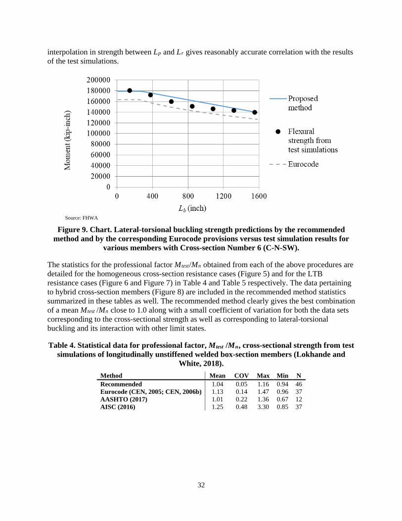
32
interpolation in strength between Lp and Lr gives reasonably accurate correlation with the results of the test simulations.
Source: FHWA
Figure 9. Chart. Lateral-torsional buckling strength predictions by the recommended method and by the corresponding Eurocode provisions versus test simulation results for
various members with Cross-section Number 6 (C-N-SW).
The statistics for the professional factor Mtest/Mn obtained from each of the above procedures are detailed for the homogeneous cross-section resistance cases (Figure 5) and for the LTB resistance cases (Figure 6 and Figure 7) in Table 4 and Table 5 respectively. The data pertaining to hybrid cross-section members (Figure 8) are included in the recommended method statistics summarized in these tables as well. The recommended method clearly gives the best combination of a mean Mtest /Mn close to 1.0 along with a small coefficient of variation for both the data sets corresponding to the cross-sectional strength as well as corresponding to lateral-torsional buckling and its interaction with other limit states.
Table 4. Statistical data for professional factor, Mtest /Mn, cross-sectional strength from test simulations of longitudinally unstiffened welded box-section members (Lokhande and
White, 2018). Method Mean COV Max Min N Recommended 1.04 0.05 1.16 0.94 46 Eurocode (CEN, 2005; CEN, 2006b) 1.13 0.14 1.47 0.96 37 AASHTO (2017) 1.01 0.22 1.36 0.67 12 AISC (2016) 1.25 0.48 3.30 0.85 37
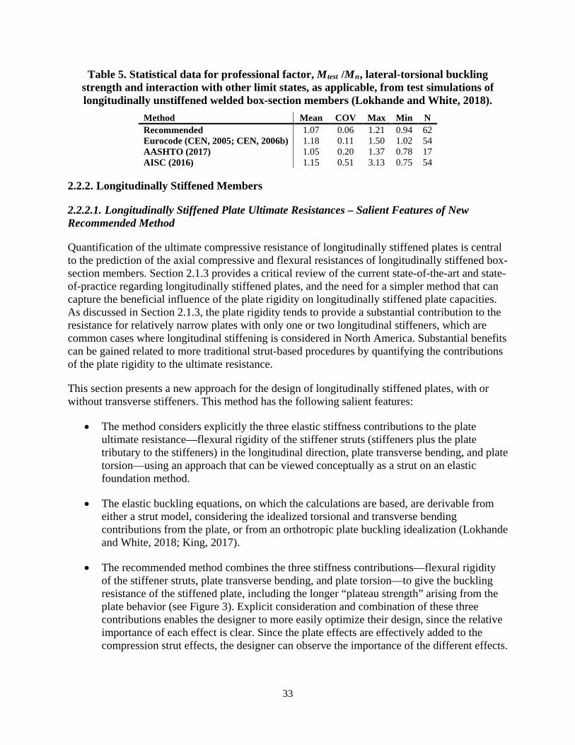
33
Table 5. Statistical data for professional factor, Mtest /Mn, lateral-torsional buckling strength and interaction with other limit states, as applicable, from test simulations of longitudinally unstiffened welded box-section members (Lokhande and White, 2018).
Method Mean COV Max Min N Recommended 1.07 0.06 1.21 0.94 62 Eurocode (CEN, 2005; CEN, 2006b) 1.18 0.11 1.50 1.02 54 AASHTO (2017) 1.05 0.20 1.37 0.78 17 AISC (2016) 1.15 0.51 3.13 0.75 54
2.2.2. Longitudinally Stiffened Members
2.2.2.1. Longitudinally Stiffened Plate Ultimate Resistances – Salient Features of New Recommended Method
Quantification of the ultimate compressive resistance of longitudinally stiffened plates is central to the prediction of the axial compressive and flexural resistances of longitudinally stiffened box-section members. Section 2.1.3 provides a critical review of the current state-of-the-art and state-of-practice regarding longitudinally stiffened plates, and the need for a simpler method that can capture the beneficial influence of the plate rigidity on longitudinally stiffened plate capacities. As discussed in Section 2.1.3, the plate rigidity tends to provide a substantial contribution to the resistance for relatively narrow plates with only one or two longitudinal stiffeners, which are common cases where longitudinal stiffening is considered in North America. Substantial benefits can be gained related to more traditional strut-based procedures by quantifying the contributions of the plate rigidity to the ultimate resistance.
This section presents a new approach for the design of longitudinally stiffened plates, with or without transverse stiffeners. This method has the following salient features:
• The method considers explicitly the three elastic stiffness contributions to the plate ultimate resistance—flexural rigidity of the stiffener struts (stiffeners plus the plate tributary to the stiffeners) in the longitudinal direction, plate transverse bending, and plate torsion—using an approach that can be viewed conceptually as a strut on an elastic foundation method.
• The elastic buckling equations, on which the calculations are based, are derivable from either a strut model, considering the idealized torsional and transverse bending contributions from the plate, or from an orthotropic plate buckling idealization (Lokhande and White, 2018; King, 2017).
• The recommended method combines the three stiffness contributions—flexural rigidity of the stiffener struts, plate transverse bending, and plate torsion—to give the buckling resistance of the stiffened plate, including the longer “plateau strength” arising from the plate behavior (see Figure 3). Explicit consideration and combination of these three contributions enables the designer to more easily optimize their design, since the relative importance of each effect is clear. Since the plate effects are effectively added to the compression strut effects, the designer can observe the importance of the different effects.
34
• In addition, the buckling length of the longitudinal stiffeners is provided by the method; therefore, the mode shape is clear to the designer and the spacing of transverse stiffeners or diaphragms can be optimized. The designer can see what the effective buckling length is without transverse stiffeners, facilitating the choice of the spacing of transverse stiffeners or diaphragms.
• The method utilizes a form of the plate effective width equations discussed in Section 2.2.1.1 to account for plate local buckling and postbuckling effects within the longitudinally stiffened plate panels. The formula for the longitudinal stiffener rigidity requirement in AASHTO LRFD Article 6.11.11.2 limits the quantification of longitudinally stiffened plate resistance to the plate buckling load with a buckling coefficient of 4.0 (no consideration of plate postbuckling resistance).
• The method avoids the limitations of the AASHTO LRFD method in Articles 6.11.8 and C6.11.11.2, discussed in Section 2.1.3. For plates with more than two longitudinal stiffeners, the longitudinal stiffeners behave predominantly like compression members spanning between the transverse stiffeners. The key property of a compression member is its moment of inertia. If this moment of inertia is not a variable in the resistance formula, which is the case in AASHTO Article C6.11.11.2, the formula cannot respond to the key design parameter. The recommended method focuses directly on the design of the longitudinal stiffener and its tributary plate width for the longitudinal compression they are subjected to.
• The recommended combination of the three stiffness contributions avoids anomalies that occur for certain geometries in Eurocode 3, Part 1.5, where due to the attributes of the interpolation between the buckling curve for an unstiffened plate and the buckling curve for a compression member, one can obtain a reduction in capacity with a change in the design characteristics where logically the strength should be increasing.
• The recommended method avoids the problem of lengthy separate strut and plate calculations followed by interpolation between these strengths.
• The method does not require any iteration and is suitable for application in a design office by spreadsheet or pencil and paper calculations. There is only one set of calculations to complete, and these calculations address both stiffened plates without or with transverse stiffeners.
2.2.2.2. Longitudinally Stiffened Plate Ultimate Resistances – Essentials of the Recommended Calculations
The essential calculations associated with the recommended method are outlined below. The details of the method are provided in the recommended Specification provisions listed in Chapter 3, Section 3.1.1.
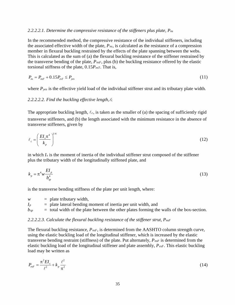
35
2.2.2.2.1. Determine the compressive resistance of the stiffeners plus plate, Pns
In the recommended method, the compressive resistance of the individual stiffeners, including the associated effective width of the plate, Pns, is calculated as the resistance of a compression member in flexural buckling restrained by the effects of the plate spanning between the webs. This is calculated as the sum of (a) the flexural buckling resistance of the stiffener restrained by the transverse bending of the plate, PnsF, plus (b) the buckling resistance offered by the elastic torsional stiffness of the plate, 0.15PesT. That is,
0.15ns nsF esT yesP P P P= + ≤ (11)
where Pyes is the effective yield load of the individual stiffener strut and its tributary plate width.
2.2.2.2.2. Find the buckling effective length,c
The appropriate buckling length, c, is taken as the smaller of (a) the spacing of sufficiently rigid transverse stiffeners, and (b) the length associated with the minimum resistance in the absence of transverse stiffeners, given by
1/44s
cp
EIk
π=
(12)
in which Is is the moment of inertia of the individual stiffener strut composed of the stiffener plus the tributary width of the longitudinally stiffened plate, and
44
pp
sp
EIk w
b= π (13)
is the transverse bending stiffness of the plate per unit length, where:
w = plate tributary width, Ip = plate lateral bending moment of inertia per unit width, and bsp = total width of the plate between the other plates forming the walls of the box-section.
2.2.2.2.3. Calculate the flexural buckling resistance of the stiffener strut, PnsF
The flexural buckling resistance, PnsF, is determined from the AASHTO column strength curve, using the elastic buckling load of the longitudinal stiffener, which is increased by the elastic transverse bending restraint (stiffness) of the plate. Put alternately, PnsF is determined from the elastic buckling load of the longitudinal stiffener and plate assembly, PesF. This elastic buckling load may be written as
2 2
2 2s
esF pEIP kπ
= +π
(14)

36
where is the effective buckling length.
2.2.2.2.4. Calculate the contribution to the buckling resistance from plate torsion, 0.15PesT
The flexural buckling resistance, PnFB, of a column does not have the longer plateau that plates are known to exhibit since the AASHTO column strength curve has no plateau (in the Eurocodes, a much shorter strength plateau is defined for columns compared to that for plates). In the recommended method, the longer plateau is provided by the elastic torsional contribution of the plate, PesT, multiplied by a calibration factor (determined from plate test simulation studies) of 0.15. The theoretical contribution from torsional rigidity of the plate to the elastic buckling load is obtained (from orthotropic plate theory, or approximately from an idealized model of the twisting of the plate between the stiffeners (Lokhande and White, 2018; King, 2017)) as
( )
32
2 31sp
esTsp
GwtP
bπ
=−ν
(15)
It is well known that the plate torsional stiffness is a key contributor to the stability of plate elements stressed to yield (e.g., see Baker et al., (1956) and Horne, (1964)). The torsional stiffness of the plate is reduced by yielding, but not as much as the lateral bending stiffness. For ideal concentric axial compression on a perfectly flat plate, incremental plasticity theory predicts that the elastic torsional stiffness of the plate is unaffected by the plasticity. For an initially imperfect plate, the torsional stiffness still is significant compared to the available transverse bending stiffness for the plate in its yielded condition. This is due to the fact that the shearing actions associated with torsion are a significant deviation from the loading normal to the yield surface of the plate material associated with the plate axial compression.
This behavior is handled in an approximate, calibrated way in the recommended method by adding PesT, multiplied by the calibration factor of 0.15, to PnsF (see Equation 11). It should be noted that PesT is added directly with PesF to obtain the elastic buckling resistance of the stiffened plate according to orthotropic plate theory, or according to a column on elastic foundation idealization considering the transverse bending of the plate and the torsion of the plate between the edges of the stiffened plate panels (Lokhande and White, 2018; King, 2017).
2.2.2.2.5. Quantify the resistance of the plate panels restrained by the other walls of the box-section, PnR
Along the edges of the total width of the longitudinally stiffened plate, the plate is restrained from out-of-plane bending by the other walls of the box-section. At the ultimate resistance of the box-section member, this plate area sustains a higher stress than the area around the longitudinal stiffeners due to this restraint. Finite element test simulations show that the ultimate strength of the stiffened plate often tends be reached before these restrained areas reach their yield stress, but that the axial stress is larger than the average stress in the stiffeners. Therefore, the resistance of the restrained areas, PnR, should be limited to less than the yield load in most cases. A reasonable approximation, based on calibration from finite element test simulations, is
37
1 0.45ns nsnsyspnR gR yeR yeR
yes yeses
P PPFP A P PP PA − += + ≤
(16)
which is basically a linear interpolation between (a) the yield load of the plate tributary to the edge, in the limit that Pns = PyeR, and (b) the compression force given by 0.45(Fysp + Pns/Aes) acting on AgR, in the limit that Pns is small, where:
Fysp = yield stress of the plate and longitudinal stiffeners, Aes = effective area of an individual stiffener strut, including the plate tributary to the
stiffener, AgR = gross tributary area of the laterally-restrained longitudinal edge of the longitudinally
stiffened plate, and PyeR = effective yield load of the tributary width of the plate at a laterally restrained
longitudinal edge.
2.2.2.2.6. Sum the resistances to determine the total resistance of the longitudinally stiffened plate, Pnsp
The total resistance of the longitudinally stiffened plate subjected to uniform axial compression, Pnsp, is calculated as the sum of the resistances of (a) each stiffener strut, including the associated effective width of the plate, Pns, and (b) each effective width of plate located at the restrained longitudinal plate edges, PnR. That is,
2nsp ns nRP nP P= + (17)
2.2.2.3. Longitudinally Stiffened Plate Ultimate Resistances – Evaluation of the Recommended Method
The performance of the recommended method is demonstrated below based on another finite element test simulation parametric study. Useful experimental results exist; however, the experimental data is relatively limited. Comparisons to experimental test results are provided in Lokhande and White (2018) and are summarized in the following. Generally, it is found that the predictions using the recommended method correlate well with the benchmark results, and provide significantly better correlation than the predictions using the methods in AASHTO (2017), AISI (2016) and Eurocode 3, Part 1-5 (CEN 2006b).
A total of 118 cases are evaluated, one-half involving flat plate longitudinal stiffeners and one-half considering T-section longitudinal stiffeners of equal area. Complete details of the studies are provided in Lokhande and White (2018). The stiffener cross-sections in all cases are designed to minimally satisfy the plate b/t limits to guard against local buckling. In addition the T-section stiffeners are sized minimally to guard against a torsional buckling (tripping) failure about their line attached to the plate. The T-section stiffeners, having equal area and sized based on these requirements, tend to have a slightly smaller normalized ratio of the stiffener strut flexural rigidity to the flexural rigidity of the tributary plate, Is/wIp. The parallel studies with flat plate and T-section stiffeners showed little difference in the ultimate resistance of the plates as a

38
function of the type of stiffener, and little difference in the predictions obtained using the recommended method.
The above studies are subdivided into two groups. The first group focuses on long and narrow plates with one or two longitudinal stiffeners and no intermediate transverse stiffeners. The second group considers wide plates with three or five longitudinal stiffeners and three intermediate transverse stiffeners. For the first group, the total length of the plate is set equal to 5c, where c is the characteristic buckling length given by Equation 12. The total length of the
plate for the second group of tests is taken as 4, where is the transverse stiffener spacing. The transverse stiffeners are modeled as a rigid transverse displacement constraint with the plates being free to rotate about the line of the rigid support.
Table 6 lists the values for three of the five nondimensional parameters that can be employed to describe the elastic buckling resistance of a longitudinally stiffened plate - the number of longitudinal stiffeners, n, the width to thickness ratio of the plate panels, w/tsp, and the gross stiffener strut area (including the tributary area of the plate) divided by the tributary area of the plate, Ags/wtsp. The other two nondimensional parameters are Is/wIp, discussed above, and /c, taken equal to 1.0 for a long narrow plate, and taken as the ratio of the transverse stiffener spacing to the characteristic length for a wide plate with intermediate transverse stiffeners and
< c.
Table 6. Nondimensional parameters for Group 1 longitudinally stiffened plate test simulations.
Test # n sp
wt
gs
sp
Awt
Test # n sp
wt
gs
sp
Awt
1 1 20 1.05 16 2 40 1.15 2 1 20 1.10 17 2 40 1.20 3 1 20 1.20 18 2 40 1.30 4 1 20 1.40 19 2 40 1.40 5 2 20 1.07 20 2 40 1.60 6 2 20 1.10 21 1 60 1.20 7 2 20 1.16 22 1 60 1.30 8 2 20 1.25 23 1 60 1.40 9 2 20 1.40 24 1 60 1.50
10 2 20 1.60 25 1 60 1.60 11 1 40 1.15 26 2 60 1.20 12 1 40 1.20 27 2 60 1.32 13 1 40 1.30 28 2 60 1.48 14 1 40 1.40 29 2 60 1.60 15 1 40 1.60
Table 7 lists the values for the same three nondimensional parameters shown in Table 6, corresponding to the second group of test simulations, involving wide plates with both longitudinal and transverse stiffening. In these tests, transverse stiffeners are spaced at < c
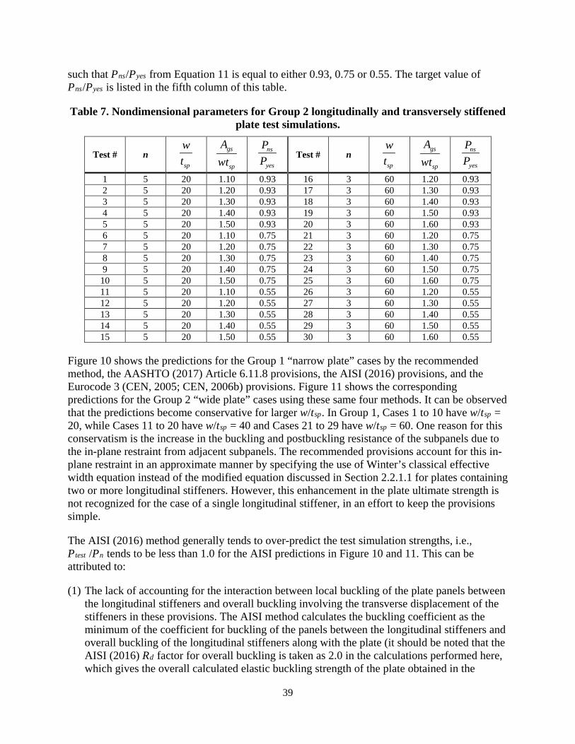
39
such that Pns/Pyes from Equation 11 is equal to either 0.93, 0.75 or 0.55. The target value of Pns/Pyes is listed in the fifth column of this table.
Table 7. Nondimensional parameters for Group 2 longitudinally and transversely stiffened plate test simulations.
Test # n sp
wt
gs
sp
Awt
ns
yes
PP
Test # n sp
wt
gs
sp
Awt
ns
yes
PP
1 5 20 1.10 0.93 16 3 60 1.20 0.93 2 5 20 1.20 0.93 17 3 60 1.30 0.93 3 5 20 1.30 0.93 18 3 60 1.40 0.93 4 5 20 1.40 0.93 19 3 60 1.50 0.93 5 5 20 1.50 0.93 20 3 60 1.60 0.93 6 5 20 1.10 0.75 21 3 60 1.20 0.75 7 5 20 1.20 0.75 22 3 60 1.30 0.75 8 5 20 1.30 0.75 23 3 60 1.40 0.75 9 5 20 1.40 0.75 24 3 60 1.50 0.75
10 5 20 1.50 0.75 25 3 60 1.60 0.75 11 5 20 1.10 0.55 26 3 60 1.20 0.55 12 5 20 1.20 0.55 27 3 60 1.30 0.55 13 5 20 1.30 0.55 28 3 60 1.40 0.55 14 5 20 1.40 0.55 29 3 60 1.50 0.55 15 5 20 1.50 0.55 30 3 60 1.60 0.55
Figure 10 shows the predictions for the Group 1 “narrow plate” cases by the recommended method, the AASHTO (2017) Article 6.11.8 provisions, the AISI (2016) provisions, and the Eurocode 3 (CEN, 2005; CEN, 2006b) provisions. Figure 11 shows the corresponding predictions for the Group 2 “wide plate” cases using these same four methods. It can be observed that the predictions become conservative for larger w/tsp. In Group 1, Cases 1 to 10 have w/tsp = 20, while Cases 11 to 20 have w/tsp = 40 and Cases 21 to 29 have w/tsp = 60. One reason for this conservatism is the increase in the buckling and postbuckling resistance of the subpanels due to the in-plane restraint from adjacent subpanels. The recommended provisions account for this in-plane restraint in an approximate manner by specifying the use of Winter’s classical effective width equation instead of the modified equation discussed in Section 2.2.1.1 for plates containing two or more longitudinal stiffeners. However, this enhancement in the plate ultimate strength is not recognized for the case of a single longitudinal stiffener, in an effort to keep the provisions simple.
The AISI (2016) method generally tends to over-predict the test simulation strengths, i.e., Ptest /Pn tends to be less than 1.0 for the AISI predictions in Figure 10 and 11. This can be attributed to:
(1) The lack of accounting for the interaction between local buckling of the plate panels between the longitudinal stiffeners and overall buckling involving the transverse displacement of the stiffeners in these provisions. The AISI method calculates the buckling coefficient as the minimum of the coefficient for buckling of the panels between the longitudinal stiffeners and overall buckling of the longitudinal stiffeners along with the plate (it should be noted that the AISI (2016) Rd factor for overall buckling is taken as 2.0 in the calculations performed here, which gives the overall calculated elastic buckling strength of the plate obtained in the

40
recommended method based on the application of orthotropic plate theory (Lokhande and White, 2018)).
(2) The use of Winter’s classical plate effective width equation to quantify the stability effects on the overall longitudinally stiffened plate ultimate strength, given the above estimate of the elastic buckling resistance.
Source: FHWA
Figure 10. Chart. Comparison of predicted strengths to the results from finite element test simulations for the Group 1 tests using flat plate longitudinal stiffeners.
The AISI method works best for the tests where the failure mode is either dominated by local buckling of the plate panels between the longitudinal stiffeners or overall buckling of the longitudinally stiffened plate with little evidence of local buckling between the stiffeners, i.e., for the Group 1 (Figure 10) Cases 1, 2, 3, 4, 21, 22, 23, 24 and 25, and for the Group 2 (Figure 11) Cases 1, 2, 3, 4, 5, 16, 17, 18, 19 and 20. For cases with a failure mode such as that shown in Figure 12, the AISI method does not work as well.
As noted in the previous discussions, the longitudinal stiffeners in wide plates with more than two longitudinal stiffeners tend to behave as disconnected struts. The key property influencing the compressive resistance of these types of plates is the moment of inertia of the longitudinal stiffener struts. However, as discussed in Section 2.2.2.1, the AASHTO plate buckling coefficient for these types of plates is independent of this key property. This is the reason why the AASHTO (2017) method does not show good correlation with the results from the test simulations for the Group 2 cases (Figure 11). Furthermore, in some of the test simulations with w/tsp = 40 and 60, where the buckling mode is dominated by local buckling of the plate panels between the longitudinal stiffeners, e.g., Group 2 Case 30, the AASHTO solution is substantially conservative because it neglects the significant postbuckling resistance of the longitudinally stiffened plate subpanels.
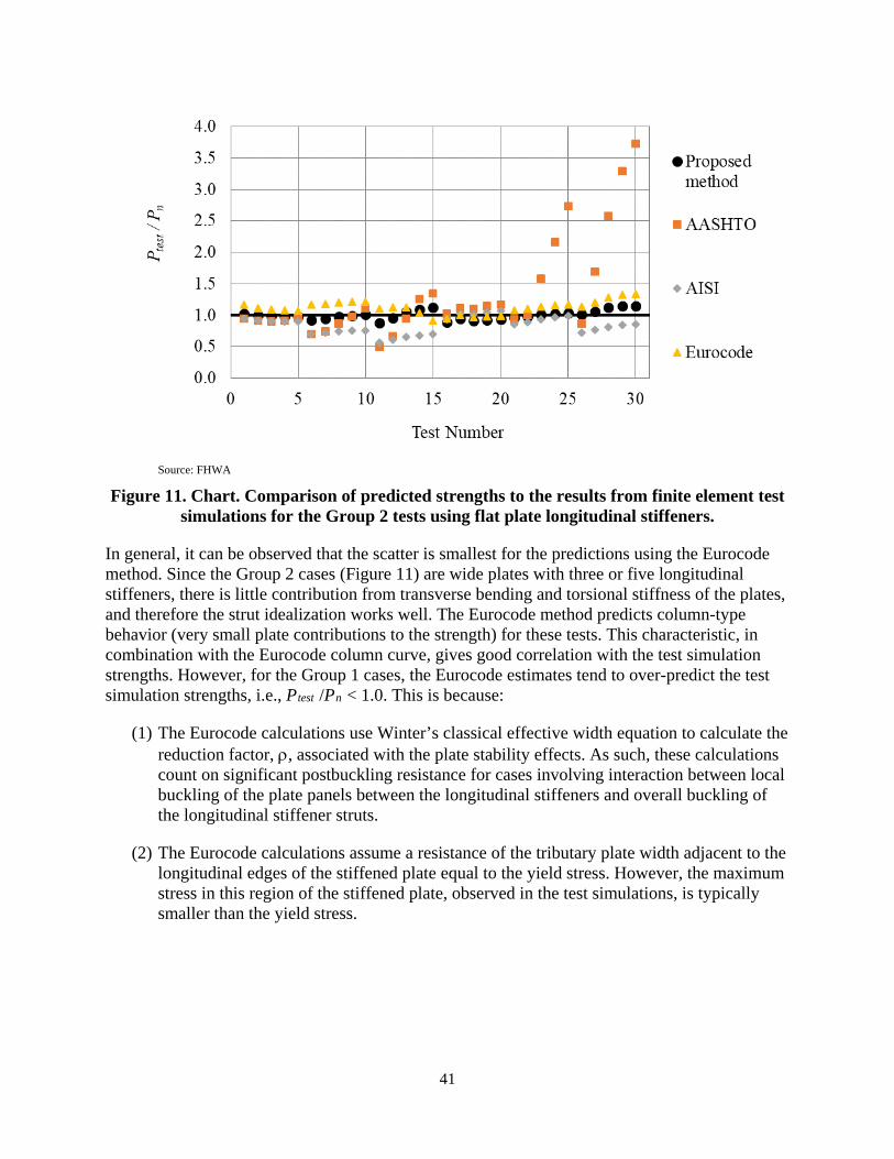
41
Source: FHWA
Figure 11. Chart. Comparison of predicted strengths to the results from finite element test simulations for the Group 2 tests using flat plate longitudinal stiffeners.
In general, it can be observed that the scatter is smallest for the predictions using the Eurocode method. Since the Group 2 cases (Figure 11) are wide plates with three or five longitudinal stiffeners, there is little contribution from transverse bending and torsional stiffness of the plates, and therefore the strut idealization works well. The Eurocode method predicts column-type behavior (very small plate contributions to the strength) for these tests. This characteristic, in combination with the Eurocode column curve, gives good correlation with the test simulation strengths. However, for the Group 1 cases, the Eurocode estimates tend to over-predict the test simulation strengths, i.e., Ptest /Pn < 1.0. This is because:
(1) The Eurocode calculations use Winter’s classical effective width equation to calculate the reduction factor, ρ, associated with the plate stability effects. As such, these calculations count on significant postbuckling resistance for cases involving interaction between local buckling of the plate panels between the longitudinal stiffeners and overall buckling of the longitudinal stiffener struts.
(2) The Eurocode calculations assume a resistance of the tributary plate width adjacent to the longitudinal edges of the stiffened plate equal to the yield stress. However, the maximum stress in this region of the stiffened plate, observed in the test simulations, is typically smaller than the yield stress.
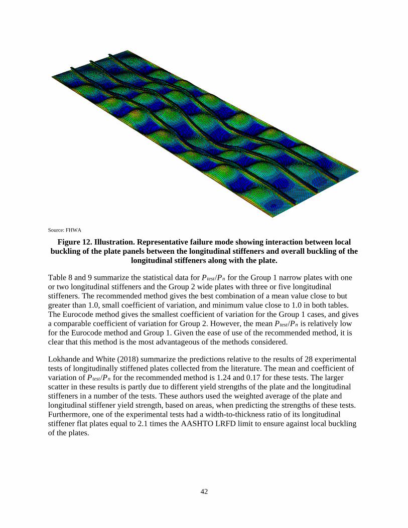
42
Source: FHWA
Figure 12. Illustration. Representative failure mode showing interaction between local buckling of the plate panels between the longitudinal stiffeners and overall buckling of the
longitudinal stiffeners along with the plate.
Table 8 and 9 summarize the statistical data for Ptest/Pn for the Group 1 narrow plates with one or two longitudinal stiffeners and the Group 2 wide plates with three or five longitudinal stiffeners. The recommended method gives the best combination of a mean value close to but greater than 1.0, small coefficient of variation, and minimum value close to 1.0 in both tables. The Eurocode method gives the smallest coefficient of variation for the Group 1 cases, and gives a comparable coefficient of variation for Group 2. However, the mean Ptest/Pn is relatively low for the Eurocode method and Group 1. Given the ease of use of the recommended method, it is clear that this method is the most advantageous of the methods considered.
Lokhande and White (2018) summarize the predictions relative to the results of 28 experimental tests of longitudinally stiffened plates collected from the literature. The mean and coefficient of variation of Ptest/Pn for the recommended method is 1.24 and 0.17 for these tests. The larger scatter in these results is partly due to different yield strengths of the plate and the longitudinal stiffeners in a number of the tests. These authors used the weighted average of the plate and longitudinal stiffener yield strength, based on areas, when predicting the strengths of these tests. Furthermore, one of the experimental tests had a width-to-thickness ratio of its longitudinal stiffener flat plates equal to 2.1 times the AASHTO LRFD limit to ensure against local buckling of the plates.
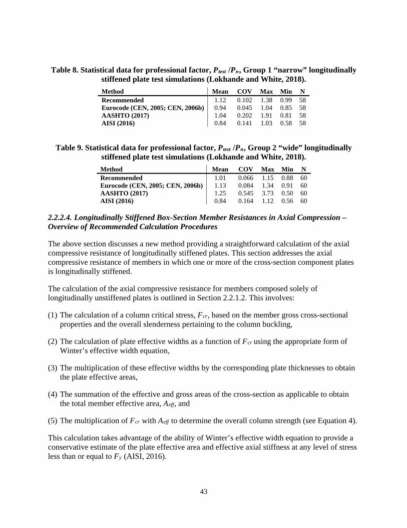
43
Table 8. Statistical data for professional factor, Ptest /Pn, Group 1 “narrow” longitudinally stiffened plate test simulations (Lokhande and White, 2018). Method Mean COV Max Min N Recommended 1.12 0.102 1.38 0.99 58 Eurocode (CEN, 2005; CEN, 2006b) 0.94 0.045 1.04 0.85 58 AASHTO (2017) 1.04 0.202 1.91 0.81 58 AISI (2016) 0.84 0.141 1.03 0.58 58
Table 9. Statistical data for professional factor, Ptest /Pn, Group 2 “wide” longitudinally stiffened plate test simulations (Lokhande and White, 2018). Method Mean COV Max Min N Recommended 1.01 0.066 1.15 0.88 60 Eurocode (CEN, 2005; CEN, 2006b) 1.13 0.084 1.34 0.91 60 AASHTO (2017) 1.25 0.545 3.73 0.50 60 AISI (2016) 0.84 0.164 1.12 0.56 60
2.2.2.4. Longitudinally Stiffened Box-Section Member Resistances in Axial Compression – Overview of Recommended Calculation Procedures
The above section discusses a new method providing a straightforward calculation of the axial compressive resistance of longitudinally stiffened plates. This section addresses the axial compressive resistance of members in which one or more of the cross-section component plates is longitudinally stiffened.
The calculation of the axial compressive resistance for members composed solely of longitudinally unstiffened plates is outlined in Section 2.2.1.2. This involves:
(1) The calculation of a column critical stress, Fcr, based on the member gross cross-sectional properties and the overall slenderness pertaining to the column buckling,
(2) The calculation of plate effective widths as a function of Fcr using the appropriate form of Winter’s effective width equation,
(3) The multiplication of these effective widths by the corresponding plate thicknesses to obtain the plate effective areas,
(4) The summation of the effective and gross areas of the cross-section as applicable to obtain the total member effective area, Aeff, and
(5) The multiplication of Fcr with Aeff to determine the overall column strength (see Equation 4).
This calculation takes advantage of the ability of Winter’s effective width equation to provide a conservative estimate of the plate effective area and effective axial stiffness at any level of stress less than or equal to Fy (AISI, 2016).
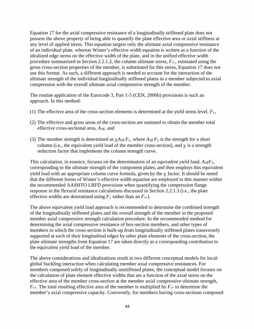
44
Equation 17 for the axial compressive resistance of a longitudinally stiffened plate does not possess the above property of being able to quantify the plate effective area or axial stiffness at any level of applied stress. This equation targets only the ultimate axial compressive resistance of an individual plate. whereas Winter’s effective width equation is written as a function of the idealized edge stress on the effective width of the plate, and in the unified effective width procedure summarized in Section 2.2.1.2, the column ultimate stress, Fcr, estimated using the gross cross-section properties of the member, is substituted for this stress, Equation 17 does not use this format. As such, a different approach is needed to account for the interaction of the ultimate strength of the individual longitudinally stiffened plates in a member subjected to axial compression with the overall ultimate axial compressive strength of the member.
The routine application of the Eurocode 3, Part 1-5 (CEN, 2006b) provisions is such an approach. In this method:
(1) The effective area of the cross-section elements is determined at the yield stress level, Fy,
(2) The effective and gross areas of the cross-section are summed to obtain the member total effective cross-sectional area, Aeff, and
(3) The member strength is determined as χAeff Fy, where Aeff Fy is the strength for a short column (i.e., the equivalent yield load of the member cross-section), and χ is a strength reduction factor that implements the column strength curve.
This calculation, in essence, focuses on the determination of an equivalent yield load, AeffFy, corresponding to the ultimate strength of the component plates, and then employs this equivalent yield load with an appropriate column curve formula, given by the χ factor. It should be noted that the different forms of Winter’s effective width equation are employed in this manner within the recommended AASHTO LRFD provisions when quantifying the compression flange response in the flexural resistance calculations discussed in Section 2.2.1.3 (i.e., the plate effective widths are determined using Fy rather than an Fcr).
The above equivalent yield load approach is recommended to determine the combined strength of the longitudinally stiffened plates and the overall strength of the member in the proposed member axial compressive strength calculation procedure. In the recommended method for determining the axial compressive resistance of box-section members, and other types of members in which the cross-section is built-up from longitudinally stiffened plates transversely supported at each of their longitudinal edges by other plate elements of the cross-section, the plate ultimate strengths from Equation 17 are taken directly as a corresponding contribution to the equivalent yield load of the member.
The above considerations and idealizations result in two different conceptual models for local-global buckling interaction when calculating member axial compressive resistances. For members composed solely of longitudinally unstiffened plates, the conceptual model focuses on the calculation of plate element effective widths that are a function of the axial stress on the effective area of the member cross-section at the member axial compressive ultimate strength, Fcr. The total resulting effective area of the member is multiplied by Fcr to determine the member’s axial compressive capacity. Conversely, for members having cross-sections composed
45
solely of longitudinally stiffened plates, the conceptual model focuses on the calculation of an equivalent yield load of the member. The axial compressive resistance of the member is then determined by employing this equivalent yield load with an appropriate column strength curve. The first of these conceptual approaches has been shown to provide appropriate axial compressive resistance solutions for members composed solely of longitudinally unstiffened plates. This approach also has been shown to have merit for sections composed of longitudinally stiffened plates (Schafer and Peköz, 1996; Schafer and Peköz, 1998), but not without adjustment to account for the reduced postbuckling capacity for buckling modes involving transverse movement of the longitudinal stiffeners. The second of these conceptual approaches is recommended as a more straightforward calculation for members having cross-sections composed solely of longitudinally stiffened plates.
The above two conceptual approaches may be combined as follows for calculation of the axial compressive resistances of members having cross-sections composed of both longitudinally unstiffened and longitudinally stiffened plates:
(1) The member nominal yield resistance is determined as
( )effos y c spnlsp c lsp
AP F bt A
= + + ∑ ∑ ∑ (18)
where:
nlsp∑ = summation over all longitudinally unstiffened cross-section plate elements.
c∑ = summation over all the corner areas of a noncomposite box-section member, and
other similar areas not included in the plate resistance calculations for other members.
lsp∑ = summation over all the longitudinally-stiffened cross-section plate elements
Ac = gross cross-sectional area of the corner pieces of a noncomposite box-section member, and other similar areas not included in the plate resistance calculations for other members.
(Aeff)sp = effective area of a longitudinally stiffened plate element under consideration
= nsp
ysp
PF
(19)
b = gross width of the longitudinally unstiffened plate element under consideration. t = thickness of the longitudinally unstiffened plate element under consideration. Fysp = specified minimum yield strength of the longitudinally stiffened plate.
(2) The nominal yield strength, Pos, is employed as follows in the AASHTO LRFD column strength curve equations:
If Pos/Pe < 2.25

46
( )[ ]/0.658 os eP Pcr yF F= (20)
Otherwise
0.877/e
cros y
PFP F
= (21)
where Pe is the theoretical elastic buckling resistance of the member subjected to concentric axial compressive load.
(3) The member nominal axial compressive resistance is then determined as
n cr effP F A= χ (22)
in which:
Ae = effective area of the member cross-section = ( )effe c sp
nlsp c lsp
Ab t A+ +∑ ∑ ∑ (23)
χ = local-global strength interaction reduction factor = 1 21 r r− (24) for noncomposite box sections containing one or more flange elements in the
direction associated with column flexural buckling in which the flange element or elements contain longitudinal stiffeners and where λmax > λr.
= 1.0
otherwise.
( )1 0.5 / 50 / 90 0sr K r= − ≥ (25)
max2 90
r
r
r λ −λ=
−λ (26)
where:
be = effective width of longitudinally unstiffened plate element, determined using the modified Winter’s effective width equation discussed in Section 2.2.1.1.
K = effective length in the plane of buckling. rs = radius of gyration about the axis normal to the plane of buckling. λmax = maximum w/t of the panels within the longitudinally stiffened flange plates. λr = 1.09 / yspE F if the flange plate has one longitudinal stiffener, or 1.49 / yspE F if
the flange plate has two or more longitudinal stiffeners.
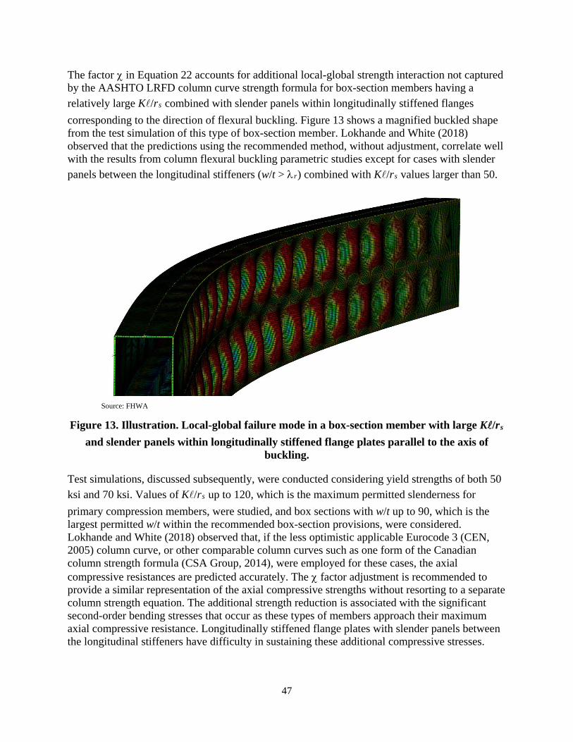
47
The factor χ in Equation 22 accounts for additional local-global strength interaction not captured by the AASHTO LRFD column curve strength formula for box-section members having a relatively large K/rs combined with slender panels within longitudinally stiffened flanges corresponding to the direction of flexural buckling. Figure 13 shows a magnified buckled shape from the test simulation of this type of box-section member. Lokhande and White (2018) observed that the predictions using the recommended method, without adjustment, correlate well with the results from column flexural buckling parametric studies except for cases with slender panels between the longitudinal stiffeners (w/t > λr) combined with K/rs values larger than 50.
Source: FHWA
Figure 13. Illustration. Local-global failure mode in a box-section member with large K/rs and slender panels within longitudinally stiffened flange plates parallel to the axis of
buckling.
Test simulations, discussed subsequently, were conducted considering yield strengths of both 50 ksi and 70 ksi. Values of K/rs up to 120, which is the maximum permitted slenderness for primary compression members, were studied, and box sections with w/t up to 90, which is the largest permitted w/t within the recommended box-section provisions, were considered. Lokhande and White (2018) observed that, if the less optimistic applicable Eurocode 3 (CEN, 2005) column curve, or other comparable column curves such as one form of the Canadian column strength formula (CSA Group, 2014), were employed for these cases, the axial compressive resistances are predicted accurately. The χ factor adjustment is recommended to provide a similar representation of the axial compressive strengths without resorting to a separate column strength equation. The additional strength reduction is associated with the significant second-order bending stresses that occur as these types of members approach their maximum axial compressive resistance. Longitudinally stiffened flange plates with slender panels between the longitudinal stiffeners have difficulty in sustaining these additional compressive stresses.
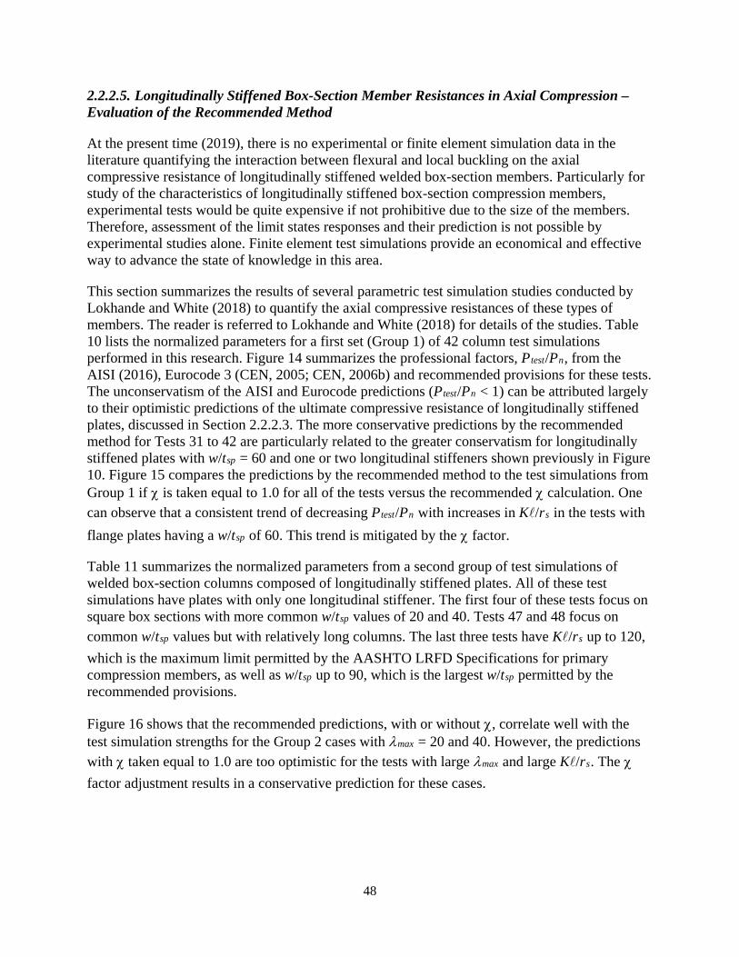
48
2.2.2.5. Longitudinally Stiffened Box-Section Member Resistances in Axial Compression – Evaluation of the Recommended Method
At the present time (2019), there is no experimental or finite element simulation data in the literature quantifying the interaction between flexural and local buckling on the axial compressive resistance of longitudinally stiffened welded box-section members. Particularly for study of the characteristics of longitudinally stiffened box-section compression members, experimental tests would be quite expensive if not prohibitive due to the size of the members. Therefore, assessment of the limit states responses and their prediction is not possible by experimental studies alone. Finite element test simulations provide an economical and effective way to advance the state of knowledge in this area.
This section summarizes the results of several parametric test simulation studies conducted by Lokhande and White (2018) to quantify the axial compressive resistances of these types of members. The reader is referred to Lokhande and White (2018) for details of the studies. Table 10 lists the normalized parameters for a first set (Group 1) of 42 column test simulations performed in this research. Figure 14 summarizes the professional factors, Ptest/Pn, from the AISI (2016), Eurocode 3 (CEN, 2005; CEN, 2006b) and recommended provisions for these tests. The unconservatism of the AISI and Eurocode predictions (Ptest/Pn < 1) can be attributed largely to their optimistic predictions of the ultimate compressive resistance of longitudinally stiffened plates, discussed in Section 2.2.2.3. The more conservative predictions by the recommended method for Tests 31 to 42 are particularly related to the greater conservatism for longitudinally stiffened plates with w/tsp = 60 and one or two longitudinal stiffeners shown previously in Figure 10. Figure 15 compares the predictions by the recommended method to the test simulations from Group 1 if χ is taken equal to 1.0 for all of the tests versus the recommended χ calculation. One can observe that a consistent trend of decreasing Ptest/Pn with increases in K/rs in the tests with flange plates having a w/tsp of 60. This trend is mitigated by the χ factor.
Table 11 summarizes the normalized parameters from a second group of test simulations of welded box-section columns composed of longitudinally stiffened plates. All of these test simulations have plates with only one longitudinal stiffener. The first four of these tests focus on square box sections with more common w/tsp values of 20 and 40. Tests 47 and 48 focus on common w/tsp values but with relatively long columns. The last three tests have K/rs up to 120, which is the maximum limit permitted by the AASHTO LRFD Specifications for primary compression members, as well as w/tsp up to 90, which is the largest w/tsp permitted by the recommended provisions.
Figure 16 shows that the recommended predictions, with or without χ, correlate well with the test simulation strengths for the Group 2 cases with λmax = 20 and 40. However, the predictions with χ taken equal to 1.0 are too optimistic for the tests with large λmax and large K/rs. The χ factor adjustment results in a conservative prediction for these cases.
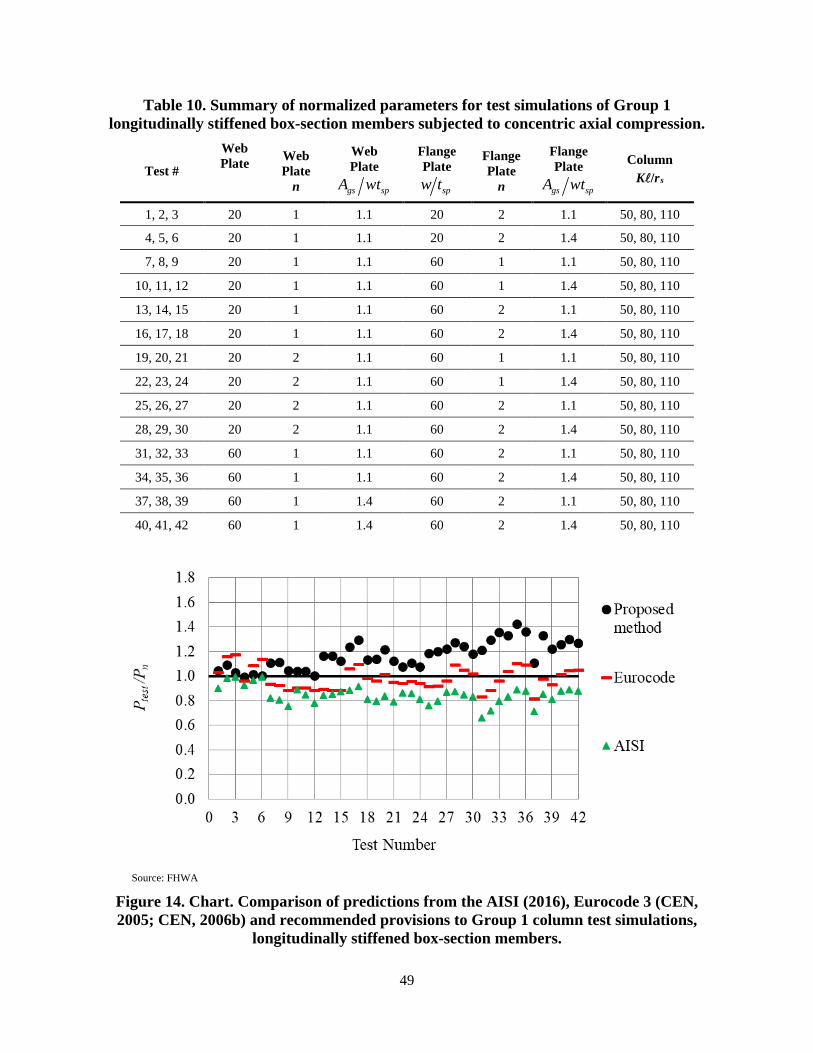
49
Table 10. Summary of normalized parameters for test simulations of Group 1 longitudinally stiffened box-section members subjected to concentric axial compression.
Test #
Web Plate
Web Plate
n
Web Plate
gs spA wt
Flange Plate
spw t
Flange Plate
n
Flange Plate
gs spA wt
Column K/rs
1, 2, 3 20 1 1.1 20 2 1.1 50, 80, 110
4, 5, 6 20 1 1.1 20 2 1.4 50, 80, 110
7, 8, 9 20 1 1.1 60 1 1.1 50, 80, 110
10, 11, 12 20 1 1.1 60 1 1.4 50, 80, 110
13, 14, 15 20 1 1.1 60 2 1.1 50, 80, 110
16, 17, 18 20 1 1.1 60 2 1.4 50, 80, 110
19, 20, 21 20 2 1.1 60 1 1.1 50, 80, 110
22, 23, 24 20 2 1.1 60 1 1.4 50, 80, 110
25, 26, 27 20 2 1.1 60 2 1.1 50, 80, 110
28, 29, 30 20 2 1.1 60 2 1.4 50, 80, 110
31, 32, 33 60 1 1.1 60 2 1.1 50, 80, 110
34, 35, 36 60 1 1.1 60 2 1.4 50, 80, 110
37, 38, 39 60 1 1.4 60 2 1.1 50, 80, 110
40, 41, 42 60 1 1.4 60 2 1.4 50, 80, 110
Source: FHWA
Figure 14. Chart. Comparison of predictions from the AISI (2016), Eurocode 3 (CEN, 2005; CEN, 2006b) and recommended provisions to Group 1 column test simulations,
longitudinally stiffened box-section members.
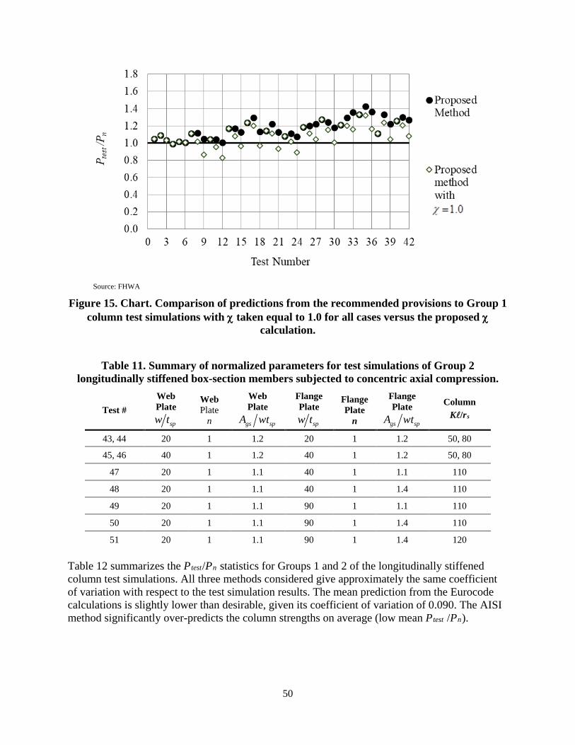
50
Source: FHWA
Figure 15. Chart. Comparison of predictions from the recommended provisions to Group 1 column test simulations with χ taken equal to 1.0 for all cases versus the proposed χ
calculation.
Table 11. Summary of normalized parameters for test simulations of Group 2 longitudinally stiffened box-section members subjected to concentric axial compression.
Test # Web Plate
spw t
Web Plate
n
Web Plate
gs spA wt
Flange Plate
spw t
Flange Plate
n
Flange Plate
gs spA wt
Column K/rs
43, 44 20 1 1.2 20 1 1.2 50, 80
45, 46 40 1 1.2 40 1 1.2 50, 80
47 20 1 1.1 40 1 1.1 110
48 20 1 1.1 40 1 1.4 110
49 20 1 1.1 90 1 1.1 110
50 20 1 1.1 90 1 1.4 110
51 20 1 1.1 90 1 1.4 120
Table 12 summarizes the Ptest/Pn statistics for Groups 1 and 2 of the longitudinally stiffened column test simulations. All three methods considered give approximately the same coefficient of variation with respect to the test simulation results. The mean prediction from the Eurocode calculations is slightly lower than desirable, given its coefficient of variation of 0.090. The AISI method significantly over-predicts the column strengths on average (low mean Ptest /Pn).
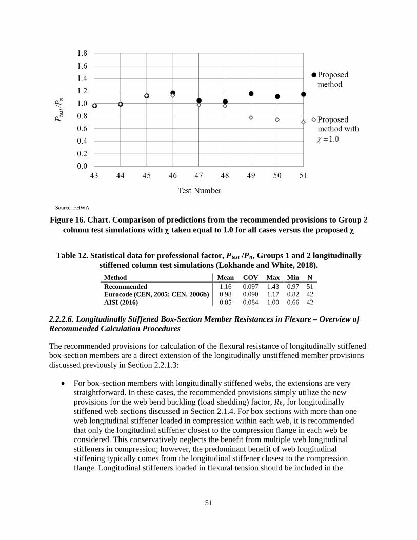
51
Source: FHWA
Figure 16. Chart. Comparison of predictions from the recommended provisions to Group 2 column test simulations with χ taken equal to 1.0 for all cases versus the proposed χ
Table 12. Statistical data for professional factor, Ptest /Pn, Groups 1 and 2 longitudinally stiffened column test simulations (Lokhande and White, 2018).
Method Mean COV Max Min N Recommended 1.16 0.097 1.43 0.97 51 Eurocode (CEN, 2005; CEN, 2006b) 0.98 0.090 1.17 0.82 42 AISI (2016) 0.85 0.084 1.00 0.66 42
2.2.2.6. Longitudinally Stiffened Box-Section Member Resistances in Flexure – Overview of Recommended Calculation Procedures
The recommended provisions for calculation of the flexural resistance of longitudinally stiffened box-section members are a direct extension of the longitudinally unstiffened member provisions discussed previously in Section 2.2.1.3:
• For box-section members with longitudinally stiffened webs, the extensions are very straightforward. In these cases, the recommended provisions simply utilize the new provisions for the web bend buckling (load shedding) factor, Rb, for longitudinally stiffened web sections discussed in Section 2.1.4. For box sections with more than one web longitudinal stiffener loaded in compression within each web, it is recommended that only the longitudinal stiffener closest to the compression flange in each web be considered. This conservatively neglects the benefit from multiple web longitudinal stiffeners in compression; however, the predominant benefit of web longitudinal stiffening typically comes from the longitudinal stiffener closest to the compression flange. Longitudinal stiffeners loaded in flexural tension should be included in the
52
calculation of the cross-section gross and effective cross-section properties except as noted otherwise in the discussions below.
• In cases where longitudinal stiffeners are placed on the tension flange, the contribution of the longitudinal stiffeners may be considered in the calculation of the cross-section properties using basic strength of materials principles.
• For box-section members with a longitudinally stiffened compression flange, the recommended provisions work directly from the provisions outlined previously in Section 2.2.1.3. However, since longitudinally stiffened compression flanges typically are unable to withstand inelastic deformations necessary to develop significant yielding throughout the depth of the box-section webs without significant reductions in their compressive resistance, the largest possible flexural resistance of these types of members is in most cases limited to the effective yield moment, Myce. That is, box-section members with a longitudinally stiffened compression flange are classified as slender web sections, i.e., Rpc = 1.0. Because of the longitudinal stiffening of the compression flange, Rf is also taken equal to 1.0. (In cases where flange longitudinal stiffeners are provided but are not required for strength, the recommended provisions indicate that the longitudinal stiffeners may be neglected and the compression flange may be considered as longitudinally unstiffened for purposes of calculating the member strength; however, the requirements pertaining to longitudinal stiffeners are to be satisfied for such sections.)
For the purpose of calculating the yield moment of the effective cross-section with respect to the compression flange, it is recommended that a longitudinally stiffened compression flange be represented by an effective area “strip” of infinitesimal thickness located at the centroid of the gross area of the entire flange plate and its longitudinal stiffener(s). This effective area may be calculated as
/eff nsp ycA P F= (27)
where Pnsp is the longitudinally stiffened plate capacity determined as described in Section 2.2.2.2. AISI (2016) and Eurocode 3 Part 1-5 (CEN, 2006b) employ a comparable approach.
All of the other calculations for longitudinally stiffened flange box-sections are essentially the same as for longitudinally unstiffened flange sections. In cases where Sxte < Sxce, it is recommended that Dce and Myce, considering the early yielding in flexural tension, should be calculated by: (1) using the value given by Equation 27 for the effective compression flange area, including the modeling of the compression flange area as a zero thickness strip at the centroid of the compression flange and its longitudinal stiffener(s), (2) modeling the web depth between the effective compression flange elevation and the elevation of a zero-thickness strip representing the tension flange area and located at the centroid of the tension flange, and (3) neglecting any web longitudinal stiffeners. This greatly simplifies the calculation of these parameters relative to the solution based on a rigorous strain-compatibility analysis.
Except as indicated in the above discussions, the areas of all longitudinal stiffeners should be included in the calculation of the gross and effective cross-section properties of the box-section.
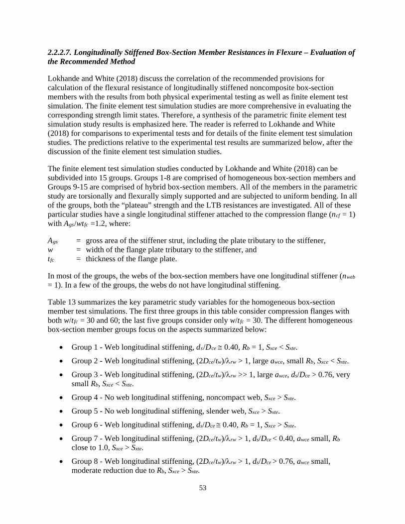
53
2.2.2.7. Longitudinally Stiffened Box-Section Member Resistances in Flexure – Evaluation of the Recommended Method
Lokhande and White (2018) discuss the correlation of the recommended provisions for calculation of the flexural resistance of longitudinally stiffened noncomposite box-section members with the results from both physical experimental testing as well as finite element test simulation. The finite element test simulation studies are more comprehensive in evaluating the corresponding strength limit states. Therefore, a synthesis of the parametric finite element test simulation study results is emphasized here. The reader is referred to Lokhande and White (2018) for comparisons to experimental tests and for details of the finite element test simulation studies. The predictions relative to the experimental test results are summarized below, after the discussion of the finite element test simulation studies.
The finite element test simulation studies conducted by Lokhande and White (2018) can be subdivided into 15 groups. Groups 1-8 are comprised of homogeneous box-section members and Groups 9-15 are comprised of hybrid box-section members. All of the members in the parametric study are torsionally and flexurally simply supported and are subjected to uniform bending. In all of the groups, both the “plateau” strength and the LTB resistances are investigated. All of these particular studies have a single longitudinal stiffener attached to the compression flange (ncf = 1) with Ags/wtfc =1.2, where:
Ags = gross area of the stiffener strut, including the plate tributary to the stiffener, w = width of the flange plate tributary to the stiffener, and tfc = thickness of the flange plate.
In most of the groups, the webs of the box-section members have one longitudinal stiffener (nweb = 1). In a few of the groups, the webs do not have longitudinal stiffening.
Table 13 summarizes the key parametric study variables for the homogeneous box-section member test simulations. The first three groups in this table consider compression flanges with both w/tfc = 30 and 60; the last five groups consider only w/tfc = 30. The different homogeneous box-section member groups focus on the aspects summarized below:
• Group 1 - Web longitudinal stiffening, ds/Dce ≅ 0.40, Rb = 1, Sxce < Sxte.
• Group 2 - Web longitudinal stiffening, (2Dce/tw)/λrw > 1, large awce, small Rb, Sxce < Sxte.
• Group 3 - Web longitudinal stiffening, (2Dce/tw)/λrw >> 1, large awce, ds/Dce > 0.76, very small Rb, Sxce < Sxte.
• Group 4 - No web longitudinal stiffening, noncompact web, Sxce > Sxte.
• Group 5 - No web longitudinal stiffening, slender web, Sxce > Sxte.
• Group 6 - Web longitudinal stiffening, ds/Dce ≅ 0.40, Rb = 1, Sxce > Sxte.
• Group 7 - Web longitudinal stiffening, (2Dce/tw)/λrw > 1, ds/Dce < 0.40, awce small, Rb close to 1.0, Sxce > Sxte.
• Group 8 - Web longitudinal stiffening, (2Dce/tw)/λrw > 1, ds/Dce > 0.76, awce small, moderate reduction due to Rb, Sxce > Sxte.
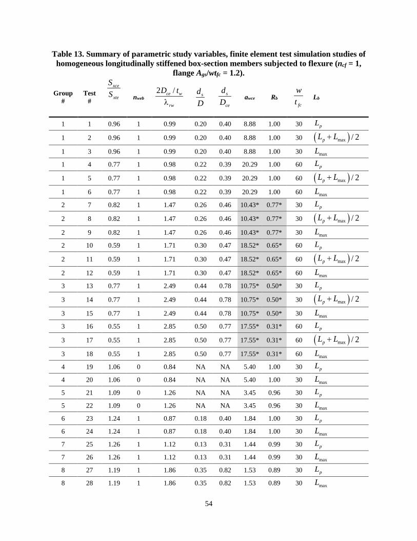
54
Table 13. Summary of parametric study variables, finite element test simulation studies of homogeneous longitudinally stiffened box-section members subjected to flexure (ncf = 1,
flange Ags/wtfc = 1.2).
Group #
Test #
xce
xte
SS
nweb 2 /ce w
rw
D tλ
sdD
s
ce
dD
awce Rb fc
wt
Lb
1 1 0.96 1 0.99 0.20 0.40 8.88 1.00 30 pL
1 2 0.96 1 0.99 0.20 0.40 8.88 1.00 30 ( )max / 2pL L+
1 3 0.96 1 0.99 0.20 0.40 8.88 1.00 30 maxL
1 4 0.77 1 0.98 0.22 0.39 20.29 1.00 60 pL
1 5 0.77 1 0.98 0.22 0.39 20.29 1.00 60 ( )max / 2pL L+
1 6 0.77 1 0.98 0.22 0.39 20.29 1.00 60 maxL
2 7 0.82 1 1.47 0.26 0.46 10.43* 0.77* 30 pL
2 8 0.82 1 1.47 0.26 0.46 10.43* 0.77* 30 ( )max / 2pL L+
2 9 0.82 1 1.47 0.26 0.46 10.43* 0.77* 30 maxL
2 10 0.59 1 1.71 0.30 0.47 18.52* 0.65* 60 pL
2 11 0.59 1 1.71 0.30 0.47 18.52* 0.65* 60 ( )max / 2pL L+
2 12 0.59 1 1.71 0.30 0.47 18.52* 0.65* 60 maxL
3 13 0.77 1 2.49 0.44 0.78 10.75* 0.50* 30 pL
3 14 0.77 1 2.49 0.44 0.78 10.75* 0.50* 30 ( )max / 2pL L+
3 15 0.77 1 2.49 0.44 0.78 10.75* 0.50* 30 maxL
3 16 0.55 1 2.85 0.50 0.77 17.55* 0.31* 60 pL
3 17 0.55 1 2.85 0.50 0.77 17.55* 0.31* 60 ( )max / 2pL L+
3 18 0.55 1 2.85 0.50 0.77 17.55* 0.31* 60 maxL
4 19 1.06 0 0.84 NA NA 5.40 1.00 30 pL
4 20 1.06 0 0.84 NA NA 5.40 1.00 30 maxL
5 21 1.09 0 1.26 NA NA 3.45 0.96 30 pL
5 22 1.09 0 1.26 NA NA 3.45 0.96 30 maxL
6 23 1.24 1 0.87 0.18 0.40 1.84 1.00 30 pL
6 24 1.24 1 0.87 0.18 0.40 1.84 1.00 30 maxL
7 25 1.26 1 1.12 0.13 0.31 1.44 0.99 30 pL
7 26 1.26 1 1.12 0.13 0.31 1.44 0.99 30 maxL
8 27 1.19 1 1.86 0.35 0.82 1.53 0.89 30 pL
8 28 1.19 1 1.86 0.35 0.82 1.53 0.89 30 maxL

55
* awce larger than 10 combined with (2Dce/tw)/λrw > 1.0, resulting in conservative estimates from the Rb equation.
Table 14 summarizes the key parametric study variables for the hybrid box-section member test simulations. All the hybrid box-section members have Grade 70 flanges and Grade 50 webs. The width-to-thickness ratio of the flange panels is w/tfc = 30 in all of the hybrid tests. The different hybrid box-section member groups focus on the following aspects:
• Group 9 - No web longitudinal stiffening, noncompact web, Sxce < Sxte.
• Group 10 - Web longitudinal stiffening, (2Dce/tw)/λrw >> 1, large awce, small Rb, Sxce < Sxte, parallels homogeneous Group 2.
• Group 11- Web longitudinal stiffening, (2Dce/tw)/λrw >> 1, large awce, ds/Dce > 0.76, very small Rb, Sxce < Sxte, parallels homogeneous Group 3.
• Group 12 - No web longitudinal stiffening, noncompact web, Sxce > Sxte, parallels homogeneous Group 4.
• Group 13 - No web longitudinal stiffening, slender web, Sxce > Sxte, parallels homogeneous Group 5.
• Group 14 - Web longitudinal stiffening, (2Dce/tw)/λrw > 1, 0.76 > ds/Dce > 0.40, awce moderate to large, Rb is small, Sxce > Sxte.
• Group 15 - Web longitudinal stiffening, (2Dce/tw)/λrw > 1, ds/Dce slightly less than 0.76, awce large, small Rb, Sxce > Sxte.
Table 14. Summary of parametric study variables, finite element test simulation studies of hybrid longitudinally stiffened box-section members subjected to flexure.
Group #
Test #
xce
xte
SS
webn 2 /ce w
rw
D tλ
sdD
s
ce
dD
awce Rb Lb
9 29 0.785 0 0.992 NA NA 20.0 1.00 pL
9 30 0.785 0 0.992 NA NA 20.0 1.00 maxL
10 31 0.764 1 2.947 0.29 0.501 10.5* 0.52* pL
10 32 0.764 1 2.947 0.29 0.501 10.5* 0.52* maxL
11 33 0.748 1 2.972 0.44 0.763 13.1* 0.42* pL
11 34 0.748 1 2.972 0.44 0.763 13.1* 0.42* maxL
12 35 1.023 0 0.959 NA NA 6.7 1.00 pL
12 36 1.023 0 0.959 NA NA 6.7 1.00 maxL
13 37 1.039 0 1.526 NA NA 4.0 0.92 pL
13 38 1.039 0 1.526 NA NA 4.0 0.92 maxL
14 39 1.174 1 2.537 0.23 0.464 8.4* 0.60* pL
14 40 1.174 1 2.537 0.23 0.464 8.4* 0.60* maxL
15 41 1.071 1 2.551 0.37 0.746 12.0* 0.56* pL
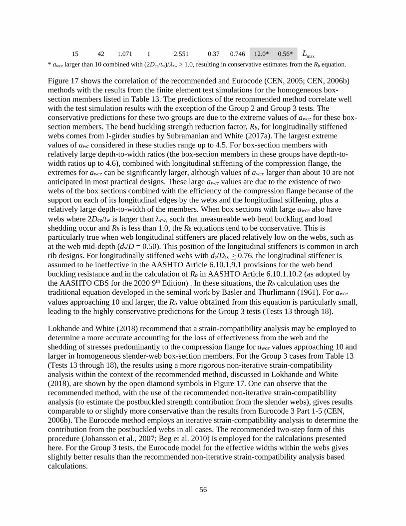
56
15 42 1.071 1 2.551 0.37 0.746 12.0* 0.56* maxL * awce larger than 10 combined with (2Dce/tw)/λrw > 1.0, resulting in conservative estimates from the Rb equation.
Figure 17 shows the correlation of the recommended and Eurocode (CEN, 2005; CEN, 2006b) methods with the results from the finite element test simulations for the homogeneous box-section members listed in Table 13. The predictions of the recommended method correlate well with the test simulation results with the exception of the Group 2 and Group 3 tests. The conservative predictions for these two groups are due to the extreme values of awce for these box-section members. The bend buckling strength reduction factor, Rb, for longitudinally stiffened webs comes from I-girder studies by Subramanian and White (2017a). The largest extreme values of awc considered in these studies range up to 4.5. For box-section members with relatively large depth-to-width ratios (the box-section members in these groups have depth-to-width ratios up to 4.6), combined with longitudinal stiffening of the compression flange, the extremes for awce can be significantly larger, although values of awce larger than about 10 are not anticipated in most practical designs. These large awce values are due to the existence of two webs of the box sections combined with the efficiency of the compression flange because of the support on each of its longitudinal edges by the webs and the longitudinal stiffening, plus a relatively large depth-to-width of the members. When box sections with large awce also have webs where 2Dce/tw is larger than λrw, such that measureable web bend buckling and load shedding occur and Rb is less than 1.0, the Rb equations tend to be conservative. This is particularly true when web longitudinal stiffeners are placed relatively low on the webs, such as at the web mid-depth (ds/D = 0.50). This position of the longitudinal stiffeners is common in arch rib designs. For longitudinally stiffened webs with ds/Dce > 0.76, the longitudinal stiffener is assumed to be ineffective in the AASHTO Article 6.10.1.9.1 provisions for the web bend buckling resistance and in the calculation of Rb in AASHTO Article 6.10.1.10.2 (as adopted by the AASHTO CBS for the 2020 9th Edition) . In these situations, the Rb calculation uses the traditional equation developed in the seminal work by Basler and Thurlimann (1961). For awce values approaching 10 and larger, the Rb value obtained from this equation is particularly small, leading to the highly conservative predictions for the Group 3 tests (Tests 13 through 18).
Lokhande and White (2018) recommend that a strain-compatibility analysis may be employed to determine a more accurate accounting for the loss of effectiveness from the web and the shedding of stresses predominantly to the compression flange for awce values approaching 10 and larger in homogeneous slender-web box-section members. For the Group 3 cases from Table 13 (Tests 13 through 18), the results using a more rigorous non-iterative strain-compatibility analysis within the context of the recommended method, discussed in Lokhande and White (2018), are shown by the open diamond symbols in Figure 17. One can observe that the recommended method, with the use of the recommended non-iterative strain-compatibility analysis (to estimate the postbuckled strength contribution from the slender webs), gives results comparable to or slightly more conservative than the results from Eurocode 3 Part 1-5 (CEN, 2006b). The Eurocode method employs an iterative strain-compatibility analysis to determine the contribution from the postbuckled webs in all cases. The recommended two-step form of this procedure (Johansson et al., 2007; Beg et al. 2010) is employed for the calculations presented here. For the Group 3 tests, the Eurocode model for the effective widths within the webs gives slightly better results than the recommended non-iterative strain-compatibility analysis based calculations.
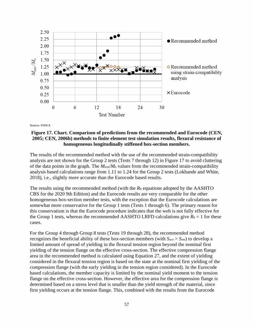
57
Source: FHWA
Figure 17. Chart. Comparison of predictions from the recommended and Eurocode (CEN, 2005; CEN, 2006b) methods to finite element test simulation results, flexural resistance of
homogeneous longitudinally stiffened box-section members.
The results of the recommended method with the use of the recommended strain-compatibility analysis are not shown for the Group 2 tests (Tests 7 through 12) in Figure 17 to avoid cluttering of the data points in the graph. The Mtest/Mn values from the recommended strain-compatibility analysis based calculations range from 1.11 to 1.24 for the Group 2 tests (Lokhande and White, 2018), i.e., slightly more accurate than the Eurocode based results.
The results using the recommended method (with the Rb equations adopted by the AASHTO CBS for the 2020 9th Edition) and the Eurocode results are very comparable for the other homogeneous box-section member tests, with the exception that the Eurocode calculations are somewhat more conservative for the Group 1 tests (Tests 1 through 6). The primary reason for this conservatism is that the Eurocode procedure indicates that the web is not fully effective for the Group 1 tests, whereas the recommended AASHTO LRFD calculations give Rb = 1 for these cases.
For the Group 4 through Group 8 tests (Tests 19 through 28), the recommended method recognizes the beneficial ability of these box-section members (with Sxce > Sxte) to develop a limited amount of spread of yielding in the flexural tension region beyond the nominal first yielding of the tension flange on the effective cross-section. The effective compression flange area in the recommended method is calculated using Equation 27, and the extent of yielding considered in the flexural tension region is based on the state at the nominal first yielding of the compression flange (with the early yielding in the tension region considered). In the Eurocode based calculations, the member capacity is limited by the nominal yield moment to the tension flange on the effective cross-section. However, the effective area for the compression flange is determined based on a stress level that is smaller than the yield strength of the material, since first yielding occurs at the tension flange. This, combined with the results from the Eurocode
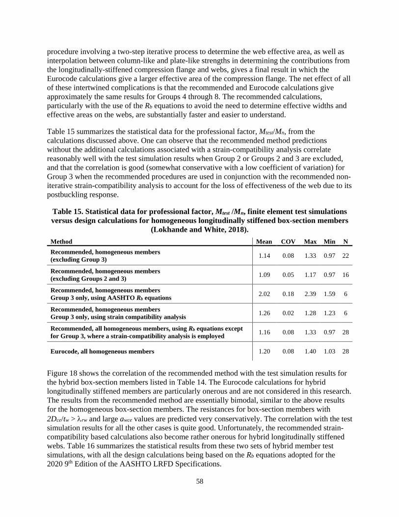
58
procedure involving a two-step iterative process to determine the web effective area, as well as interpolation between column-like and plate-like strengths in determining the contributions from the longitudinally-stiffened compression flange and webs, gives a final result in which the Eurocode calculations give a larger effective area of the compression flange. The net effect of all of these intertwined complications is that the recommended and Eurocode calculations give approximately the same results for Groups 4 through 8. The recommended calculations, particularly with the use of the Rb equations to avoid the need to determine effective widths and effective areas on the webs, are substantially faster and easier to understand.
Table 15 summarizes the statistical data for the professional factor, Mtest/Mn, from the calculations discussed above. One can observe that the recommended method predictions without the additional calculations associated with a strain-compatibility analysis correlate reasonably well with the test simulation results when Group 2 or Groups 2 and 3 are excluded, and that the correlation is good (somewhat conservative with a low coefficient of variation) for Group 3 when the recommended procedures are used in conjunction with the recommended non-iterative strain-compatibility analysis to account for the loss of effectiveness of the web due to its postbuckling response.
Table 15. Statistical data for professional factor, Mtest /Mn, finite element test simulations versus design calculations for homogeneous longitudinally stiffened box-section members
(Lokhande and White, 2018). Method Mean COV Max Min N Recommended, homogeneous members (excluding Group 3) 1.14 0.08 1.33 0.97 22
Recommended, homogeneous members (excluding Groups 2 and 3) 1.09 0.05 1.17 0.97 16
Recommended, homogeneous members Group 3 only, using AASHTO Rb equations 2.02 0.18 2.39 1.59 6
Recommended, homogeneous members Group 3 only, using strain compatibility analysis 1.26 0.02 1.28 1.23 6
Recommended, all homogeneous members, using Rb equations except for Group 3, where a strain-compatibility analysis is employed 1.16 0.08 1.33 0.97 28
Eurocode, all homogeneous members 1.20 0.08 1.40 1.03 28
Figure 18 shows the correlation of the recommended method with the test simulation results for the hybrid box-section members listed in Table 14. The Eurocode calculations for hybrid longitudinally stiffened members are particularly onerous and are not considered in this research. The results from the recommended method are essentially bimodal, similar to the above results for the homogeneous box-section members. The resistances for box-section members with 2Dce/tw > λrw and large awce values are predicted very conservatively. The correlation with the test simulation results for all the other cases is quite good. Unfortunately, the recommended strain-compatibility based calculations also become rather onerous for hybrid longitudinally stiffened webs. Table 16 summarizes the statistical results from these two sets of hybrid member test simulations, with all the design calculations being based on the Rb equations adopted for the 2020 9th Edition of the AASHTO LRFD Specifications.
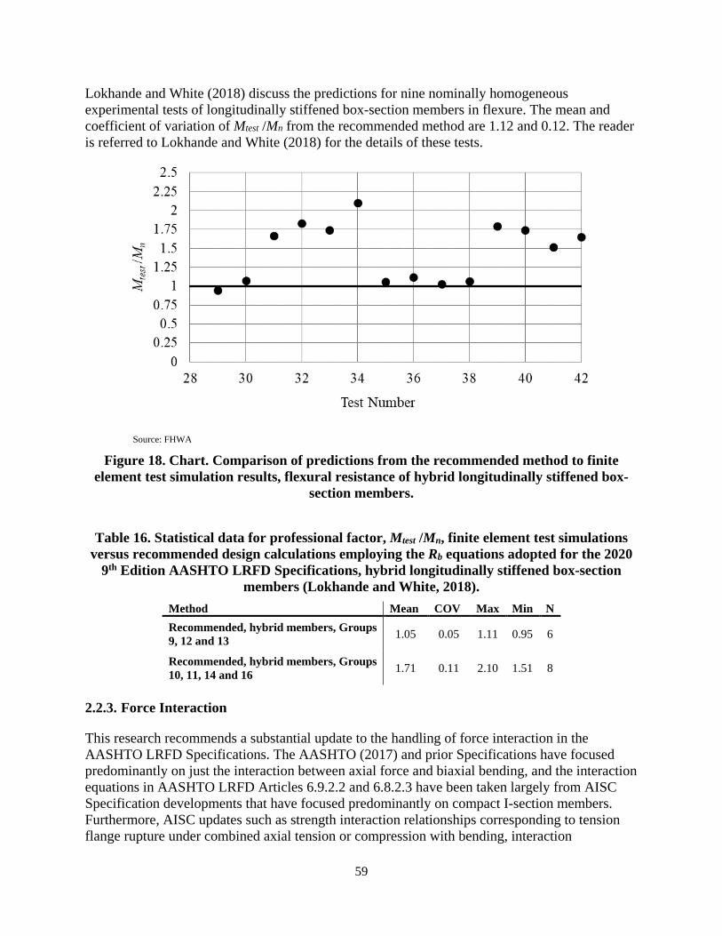
59
Lokhande and White (2018) discuss the predictions for nine nominally homogeneous experimental tests of longitudinally stiffened box-section members in flexure. The mean and coefficient of variation of Mtest /Mn from the recommended method are 1.12 and 0.12. The reader is referred to Lokhande and White (2018) for the details of these tests.
Source: FHWA
Figure 18. Chart. Comparison of predictions from the recommended method to finite element test simulation results, flexural resistance of hybrid longitudinally stiffened box-
section members.
Table 16. Statistical data for professional factor, Mtest /Mn, finite element test simulations versus recommended design calculations employing the Rb equations adopted for the 2020
9th Edition AASHTO LRFD Specifications, hybrid longitudinally stiffened box-section members (Lokhande and White, 2018).
Method Mean COV Max Min N Recommended, hybrid members, Groups 9, 12 and 13 1.05 0.05 1.11 0.95 6
Recommended, hybrid members, Groups 10, 11, 14 and 16 1.71 0.11 2.10 1.51 8
2.2.3. Force Interaction
This research recommends a substantial update to the handling of force interaction in the AASHTO LRFD Specifications. The AASHTO (2017) and prior Specifications have focused predominantly on just the interaction between axial force and biaxial bending, and the interaction equations in AASHTO LRFD Articles 6.9.2.2 and 6.8.2.3 have been taken largely from AISC Specification developments that have focused predominantly on compact I-section members. Furthermore, AISC updates such as strength interaction relationships corresponding to tension flange rupture under combined axial tension or compression with bending, interaction
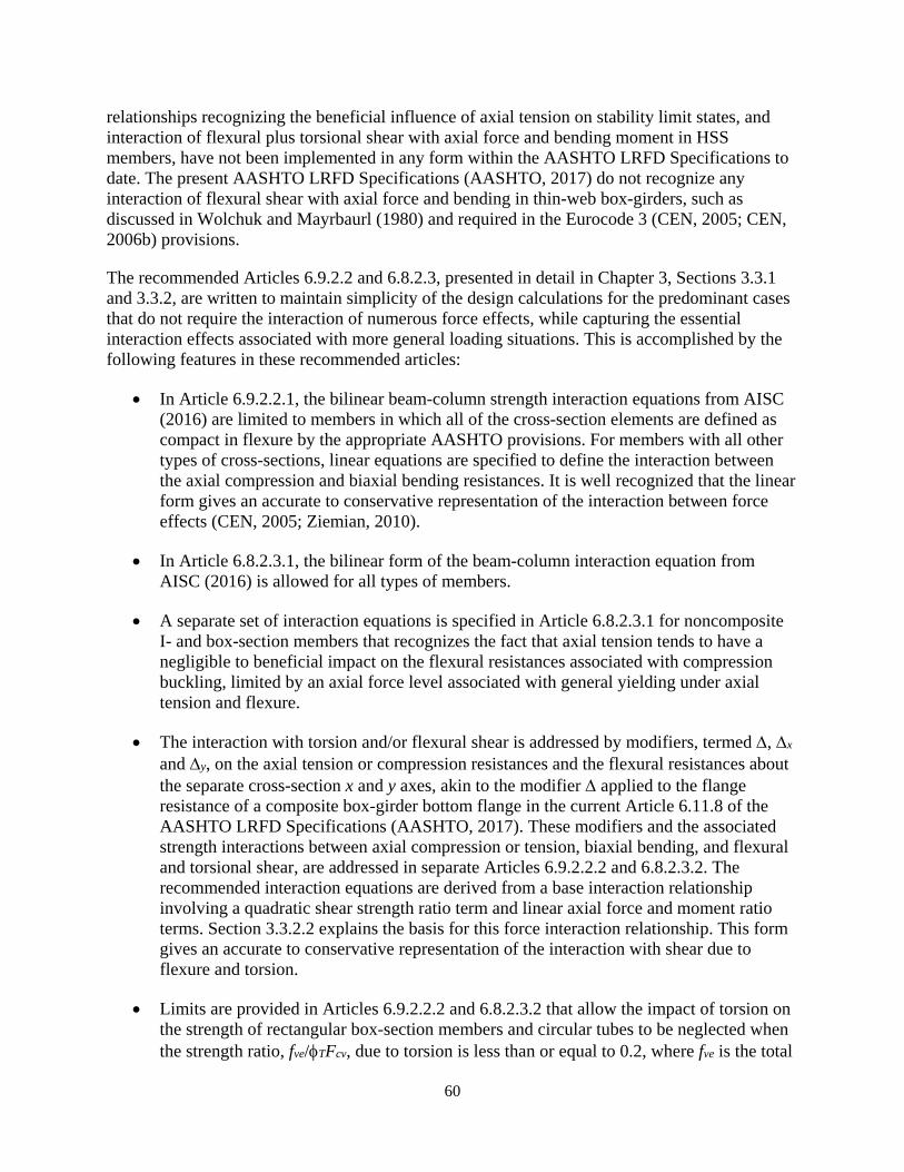
60
relationships recognizing the beneficial influence of axial tension on stability limit states, and interaction of flexural plus torsional shear with axial force and bending moment in HSS members, have not been implemented in any form within the AASHTO LRFD Specifications to date. The present AASHTO LRFD Specifications (AASHTO, 2017) do not recognize any interaction of flexural shear with axial force and bending in thin-web box-girders, such as discussed in Wolchuk and Mayrbaurl (1980) and required in the Eurocode 3 (CEN, 2005; CEN, 2006b) provisions.
The recommended Articles 6.9.2.2 and 6.8.2.3, presented in detail in Chapter 3, Sections 3.3.1 and 3.3.2, are written to maintain simplicity of the design calculations for the predominant cases that do not require the interaction of numerous force effects, while capturing the essential interaction effects associated with more general loading situations. This is accomplished by the following features in these recommended articles:
• In Article 6.9.2.2.1, the bilinear beam-column strength interaction equations from AISC (2016) are limited to members in which all of the cross-section elements are defined as compact in flexure by the appropriate AASHTO provisions. For members with all other types of cross-sections, linear equations are specified to define the interaction between the axial compression and biaxial bending resistances. It is well recognized that the linear form gives an accurate to conservative representation of the interaction between force effects (CEN, 2005; Ziemian, 2010).
• In Article 6.8.2.3.1, the bilinear form of the beam-column interaction equation from AISC (2016) is allowed for all types of members.
• A separate set of interaction equations is specified in Article 6.8.2.3.1 for noncomposite I- and box-section members that recognizes the fact that axial tension tends to have a negligible to beneficial impact on the flexural resistances associated with compression buckling, limited by an axial force level associated with general yielding under axial tension and flexure.
• The interaction with torsion and/or flexural shear is addressed by modifiers, termed ∆, ∆x and ∆y, on the axial tension or compression resistances and the flexural resistances about the separate cross-section x and y axes, akin to the modifier ∆ applied to the flange resistance of a composite box-girder bottom flange in the current Article 6.11.8 of the AASHTO LRFD Specifications (AASHTO, 2017). These modifiers and the associated strength interactions between axial compression or tension, biaxial bending, and flexural and torsional shear, are addressed in separate Articles 6.9.2.2.2 and 6.8.2.3.2. The recommended interaction equations are derived from a base interaction relationship involving a quadratic shear strength ratio term and linear axial force and moment ratio terms. Section 3.3.2.2 explains the basis for this force interaction relationship. This form gives an accurate to conservative representation of the interaction with shear due to flexure and torsion.
• Limits are provided in Articles 6.9.2.2.2 and 6.8.2.3.2 that allow the impact of torsion on the strength of rectangular box-section members and circular tubes to be neglected when the strength ratio, fve/φTFcv, due to torsion is less than or equal to 0.2, where fve is the total
61
factored shear stress due to torsion and φTFcv is the corresponding factored shear buckling resistance. This is consistent with similar guidelines in the AISC (2016) Specification for HSS subjected to combined torsion, shear, flexure and axial force. Based on the recommended interaction equations that account for the effects of torsional and/or flexural shear, this allows a theoretical reduction in the member or plate axial and/or flexural resistance due to torsional shear stress up to 4 percent before the influence of torsional shear needs to be considered.
• Additional limits are provided in Articles 6.9.2.2.2 and 6.8.2.3.2 that allow the impact of the factored flexural shear stresses on the strength of general members to be neglected when the strength ratio Pu/Pr or Pu/Pry, as applicable, is less than or equal to 0.05, where Pu is the factored member axial force, Pr is the axial compressive or tensile resistance, and Pry is the factored axial tensile resistance based on tension yielding. This recognizes the well-established fact that moment-shear strength interaction is small and may be neglected in I- and box-girder flexural members (White et al., 2008; Johansson et al, 2007; AISC, 2016). Furthermore, it is recommended that Articles C6.10.6.1 and C6.11.6.2.1 permit the axial strength ratios Pu/Pr and Pu/Pry to be neglected when these ratios are smaller than 0.05. AASHTO (2017) allows these terms to be neglected for ratios up to 0.10; however, this is in the context of the use of the bilinear beam-column strength interaction form from AISC (2016). The limits of Pu/Pr and Pu/Pry < 0.05 correspond to a theoretical reduction of 5 % in the strength before the influence of axial force should be considered in the context of a linear beam-column strength interaction equation.
• A separate Article 6.8.2.3.3 is provided under Article 6.8.2.3 that addresses the strength interaction between flexure and axial tension or compression on tension flange rupture at cross-sections containing bolt holes on flanges subjected to a net tension at connection or nonconnection locations, at member cross-sections at connection or nonconnection locations subjected to axial tension and flexure and containing bolt holes in other cross-section elements, and at tmember cross-sections at welded connections subjected to axial tension and flexure. This Article implements a generalization of the provisions from AISC (2016) for evaluation of the flange tension rupture resistance. The corresponding strength interaction equation recognizes the beneficial effect of axial compression force on this limit state check. This separate interaction equation check also provides the benefit of not requiring an interaction between member net section tension rupture and member stability limit states.
Detailed guidance is provided regarding the appropriate combination of the strength ratio terms Pu/Pr and Mux/Mrx corresponding to axial compression and to flexure about the major-axis of bending with other strength ratio terms in Chapter 3, Section 3.3.2.1. Generally speaking, it is not appropriate to simply combine the various strength ratios on just a cross-section by cross-section basis along a member’s length to determine the critical strength interaction check. The axial compressive resistance generally depends on the overall member length effects, and the major-axis bending resistance, Mrx, also depends on the overall member length effects when Mrx is governed by lateral-torsional buckling (LTB). Performing checks solely on a cross-section by cross-section basis does not sufficiently capture these length effects. In addition, due to the LTB effects associated with moment gradient and the Cb factor, it is important to note that generally

62
the maximum Mux/Mrx does not necessarily occur for the load combination that gives the maximum Mux.
The reader is referred to Chapter 3, Section 3.3.1 for the recommended provisions and to Section 3.3.2 for a detailed discussion of these provisions.
2.2.4. Service Requirements for Members Composed of Slender Plate Elements and/or Slender Longitudinally Stiffened Plate Panels
The recommended provisions have adopted and generalized the design philosophy from Articles 6.10 and 6.11 of the AASHTO LRFD Specifications that theoretical elastic local buckling is disallowed at service limit states and for constructibility for members composed of slender component plate elements and/or longitudinally stiffened plate panels supported along two longitudinal edges. The recommended Article 6.9.4.5 (see Chapter 3, Section 3.4.1) implements these checks. For members composed of slender plate elements or slender longitudinally stiffened plate panels subjected to longitudinal compressive stresses at one or both of their longitudinal edges, this article requires that the normal stress distribution at the service limit state and during construction be checked against a theoretical elastic local buckling limit. The provisions of Article 6.9.4.5 do not apply to webs of composite or noncomposite I-section members subject to flexure only, webs of composite box-section members subject to flexure only, or noncomposite box-section members subject to flexure only and containing longitudinally unstiffened webs or webs with only one longitudinal stiffener; such members are to be checked using the applicable provisions of Articles 6.10 and 6.11 using the appropriate web bend-buckling resistance specified in Article 6.10.1.9.
The recommended Article 6.12.2.2.2f (see Chapter 3, Section 3.2.1) also requires that noncomposite box-section member webs satisfy the provisions of Article 6.10.3.3 for constructibility as well as the special fatigue requirement specified in Article 6.10.5.3. These articles disallow shear buckling of the web during construction and under the unfactored permanent load plus the Fatigue I load combination.
Consistent with the philosophy in Articles 6.10 and 6.11, the effect of combined normal and shear stresses on theoretical plate buckling at the service limit states, and for constructibility, is not considered in the recommended provisions. Satisfaction of the specified requirements to separately prevent theoretical buckling under normal stresses and under shear stresses is considered sufficient as an approximate method to limit plate bending strains and out-of-plane displacements.
The above philosophy has some similarity to the philosophy of limiting “web breathing,” i.e., the cyclic movement of plate panels out-of-plane under load, in the Eurocode 3, Part 2 (CEN, 2006a) provisions for steel bridge design.
2.2.5. Design of Solid Web Arches
Another major focus of this project has been the liberalization and modernization of the AASHTO LRFD Article 6.14.4 provisions for Solid Web Arches. This is accomplished in large part by adopting the recommended provisions discussed in the above Sections 2.2.1 through 2.2.4 in calculating the axial compressive and flexural resistances, and in determining the force

63
interaction effects for the arch rib and tie members. In addition, the recommended Article 6.14.4 provisions specify a number of additional requirements directly addressing the behavior of arch ribs:
• Article 6.14.4.1 provides equations that restrict the width-to-thickness of the arch rib flanges and web longitudinal stiffeners such that there is no significant reduction in their strength due to the influence of the rib vertical curvature. The geometry of most arch ribs is such that no reduction is required due to vertical curvature effects. Additional equations are provided in this report that give a reduced effective yield strength of these components to accommodate potential cases that violate the above limits.
• Article 6.14.4.1 also states that, where longitudinal stiffeners are employed on the flanges of arch ribs, transfer of the radial load from the axial force in the longitudinal stiffeners acting through the vertical curve to the webs of the arch rib is to be considered. However, since the use of flange longitudinal stiffeners on arch ribs is less common, specific requirements are not provided. General guidance is provided in the commentary discussions.
• Article 6.14.4.2 gives a recommended not-to-exceed limit on the dfs/tw of arch ribs, where dfs is defined as the web depth for ribs with webs that are longitudinally unstiffened, or the maximum distance between the compression or tension flange and the adjacent longitudinal stiffener for ribs with webs that are longitudinally stiffened. This limit is intended to preclude the potential buckling of a flange or web longitudinal stiffener into the web, within the plane of the web. This limit is adapted from the Eurocode 3 Part 1-5 rules (CEN, 2006b) as well as from AISC (2016) Section F13. As the radius of curvature of the arch rib approaches infinity, the recommended equation gives the same limit as Equation F13-4 of the AISC (2016) Specification for longitudinally unstiffened webs.
• Lastly, Article 6.14.4.5 requires that vertical curvature effects resulting in a reduction in the rib lateral-torsional buckling (LTB) resistance be considered in evaluating the arch rib LTB limit states. These reductions occur when the arch rib is subjected to bending moments causing compression on the flange farthest from the center of curvature of the rib. For box-section arch ribs with Ldb/R > 0.20, where Ldb is the developed unbraced length along the vertical curve between the brace points, and R is the minimum radius of curvature of the arch rib measured from the mid-depth of the rib, the provisions indicate that the corresponding reduction in the LTB resistance may be estimated by multiplying the moment gradient factor, Cb, by 0.90. References are provided for more rigorous calculation of the reduced LTB resistance where merited.
2.2.6. Other Design Requirements
Various other important design requirements and practical decisions have been addressed as part of the development of the recommended provisions for design of noncomposite box-section members. These include the following:
• Web shear strength. Section 2.1.5 provides a summary of the state-of-the-art pertaining to web shear resistance. Although there are opportunities for improvement, particularly pertaining to the shear resistance of unstiffened webs, it was decided that the nature of the

64
changes to the AASHTO LRFD Specifications associated with the above considerations were already quite substantial, and that making parallel substantial changes to web shear strength provisions would unnecessarily complicate what was already a major development effort. Therefore, it was decided to utilize the current AASHTO (2017) shear strength provisions throughout this project effort.
• Shear lag. The reduction in the effectiveness of wide flanges in box-section members, relative to the member effective span length, can be significant in certain situations. Section 2.1.7 provides a detailed review of shear lag effects pertaining to strength as well as service and fatigue considerations. Further review of the literature in this area, conducted during the progress of this research, showed a substantial variation in shear lag design rules among existing references and standards. The investigators elected to recommend a simplified representation consistent with AASHTO LRFD Articles 6.11.1 and 4.6.2.6.2 for strength calculations, and for addressing shear lag in simple span members and positive moment regions of continuous-span members for the calculation of elastic flexural stresses at the service and fatigue limit states. However, given conclusive evidence that shear lag effects on elastic stresses are more severe within the negative moment regions of continuous-span members and within cantilevers, the investigators decided to provide curve-fit equations to recommendations from Wolchuk and Mayrbaurl (1980) and Wolchuk (1997) for these cases. The corresponding recommended provisions (in Article 6.12.2.2.2g) and their discussion can be found in Chapter 3, Sections 3.2.1 and 3.2.2.7.
• Diaphragm requirements, and calculation of stresses due to box-section distortion. Section 2.1.7 also provides a brief review of the state of the art pertaining to diaphragm requirements and calculation of stresses caused by distortion of the cross-section in box-section members. Given the complexities associated with the development and implementation of the box-section member provisions discussed above, given the accepted adequacy of the broad rules pertaining to these design considerations for composite box-section members implemented in the current AASHTO (2017) Specifications, and given that one of the significant opportunities for potential improvements in this area is in the development of refined analysis rules and capabilities rather than baseline design rules for routine practice, it was decided to largely parallel the current composite box-section member diaphragm requirements in this project effort. The resulting recommended provisions (Article 6.7.4.4) and their discussion are provided in Chapter 3, Sections 3.6.1 and 3.6.2.
2.3. TASK 3 – DEVELOPMENT OF SPECIFICATION PROVISIONS
The recommended Specification provisions along with discussions of groups of recommended Specification articles are provided in Chapter 3. The above summary presentations regarding the correlation of the recommended plate and member axial and flexural resistance provisions with experimental and test simulation results (primarily with test simulation results), as well as comparisons to the results for other existing methods, show consistently that the recommended provisions provide the best combination of mean professional factors close to but greater than 1.0 along with a small coefficient of variation compared to the other existing methods that have been evaluated. If the results from these studies are compared to the data employed in the development of the AASHTO LRFD (2017) Article 6.10 provisions, one can observe that the
65
means and coefficients of variation are very similar to those for the professional factors determined in the prior Article 6.10 developments, for example as summarized in Galambos (2006). A few of the means and coefficients of variation employed by Galambos (2006) for a broad reliability assessment of I-section member design rules are:
• For flexure of welded girders subjected to uniform moment: mean = 1.00, COV = 0.08
• For flexure of rolled beams subjected to uniform moment: mean = 0.99, COV = 0.06.
• For flexure of welded girders subjected to moment gradient: mean = 1.13, COV = 0.11.
• For flexure of rolled beams subjected to moment gradient: mean = 1.16, COV = 0.12.
• For shear of welded girders: mean 1.051, COV = 0.122
Based on the results provided, it can be concluded that the recommended provisions provide a level of safety comparable to that assumed in the AASHTO LRFD Article 6.10 provisions (i.e., β = 3.5).
2.4. TASK 4 –DEMONSTRATION OF THE USE OF THE RECOMMENDED PROVISONS
Design process flowcharts and three major design examples have been developed to assist engineers with the interpretation and use of the recommended provisions. Detailed flow charts are provided in Appendix A. Appendix B provides the following three detailed design examples exercising the use of the provisions:
• Truss end post: This welded nonslender longitudinally unstiffened member is subjected to axial compression, biaxial bending, shear and torsion to demonstrate the basic principles using the least complex, and most common, box-shaped member. Specific details of the structure, calculation of factored forces, and discussion of the provisions are provided. The second and third examples cover more complex cross-sections, with less detail related to the items not specific to the proposed specifications. After completion of the design, a discussion of modifications necessary for HSS members is presented.
• Tied arch tie girder: This welded slender longitudinally stiffened web member with different sized flanges is subjected to axial tension, biaxial bending, shear and torsion. The example includes the design of longitudinal and transverse stiffeners.
• Arch rib compression member: This welded member with longitudinally stiffened webs is subjected to compression, biaxial flexure, shear and torsion. This example demonstrates the requirements for the updated Article 6.14.4 on solid web arch ribs.
66
CHAPTER 3 - RECOMMENDED SPECIFICATION PROVISIONS
This chapter presents the recommended AASHTO LRFD Specification provisions. Groups of recommended Articles are provided, each being followed by a substantive discussion of the article requirements. Where useful for purposes of continuity and clarity, the existing provisions from the 7th Edition of the AASHTO LRFD Specifications and Commentary (AASHTO, 2015) are included. These provisions are highlighted in grey. These were the AASHTO Specifications in effect at the start of this research effort. A number of recommendations from the early research on this project, specifically an implementation of the AISI (2016) and AISC (2016) unified effective width method, were implemented within the 8th Edition of the AASHTO LRFD Specifications (AASHTO, 2017). Furthermore, additional updates to the 2020 9th AASHTO LRFD Specifications were approved by the AASHTO CBS in 2017. The 7th Edition of the LRFD Specifications is employed as the base from which the project recommendations are provided, to provide a clear and complete documentation of the project recommendations.
The recommended provisions are provided in the following logical order to facilitate their review and evaluation:
• Section 3.1 presents the recommended AASHTO LRFD articles that address the calculation of axial compressive resistances of non-composite box-section members, as well as other types of members employing slender and/or longitudinally stiffened component plate elements. This includes:
o Article 6.9.4.1, addressing general aspects of the calculation of member axial compressive resistances.
o Article 6.9.4.2, which addresses local buckling effects on member axial compressive resistances. This article gives recommended limits for cross-section elements to be considered as nonslender, i.e., not subject to local buckling effects. This article also provides recommended equations for effective widths for slender plate elements.
o Appendix E6, which provides equations for calculation of the axial compressive resistance of longitudinally stiffened cross-section plate elements. This appendix also addresses specific requirements for the general design of longitudinal and transverse stiffeners in plates subject to compressive normal stresses.
• Section 3.2 presents the recommended Articles 6.12.2.2.2 and 6.12.1, which address the calculation of the flexural resistance of all types of noncomposite box-section members. The specific provisions (Article 6.12.2.2.2) pertaining to these member types are presented first, followed by the related more general Article 6.12.1.2 provisions providing callouts to Article 6.12.2.2.2 as well as other pertinent articles of the AASHTO LRFD Specifications pertinent to the design of noncomposite box-section members.
• Next, Section 3.3 presents the recommended AASHTO LRFD articles addressing force interaction. This includes Article 6.9.2.2, which addresses combined axial compression, flexure and flexural and/or torsional shear. Article 6.9.2.2 is then followed by the recommended Article 6.8.2.3, which addresses combined axial tension, flexure and

67
flexural and/or torsional shear. Article 6.8.2.3 refers to Article 6.9.2.2 for the definition of a number of its equations.
• Section 3.4 then presents a recommended new AASHTO LRFD Article 6.9.4.5, addressing limits on theoretical local buckling of plates supported along two longitudinal edges due to general compressive stresses from service and construction loads.
• Section 3.5 presents a complete re-write of the AASHTO LRFD Article 6.14.4.4 on Solid Web Arches. This rewrite provides substantial improvements in the generality and accuracy of the LRFD provisions for arch design, while also achieving ease of use and consistency with the other recommended box-section member provisions.
• Lastly, Section 3.6 gives recommended provisions addressing other important miscellaneous requirements. This includes:
o A new Article 6.7.4.4, addressing diaphragm requirements for noncomposite box-section members, and
o A recommended Article C6.1 discussion for the AASHTO LRFD commentary, addressing the application of emerging methods of advanced analysis in steel bridge design and the potential of these methods.
3.1. AXIAL COMPRESSIVE RESISTANCE
3.1.1. Specification Provisions (Articles 6.9.4.1, 6.9.4.2 and Appendix E6)
6.9.4.1—Nominal Compressive Resistance
6.9.4.1.1—General
The nominal compressive resistance, Pn, shall be taken as the smallest value based on the applicable modes of flexural buckling, torsional buckling, and flexural-torsional buckling as follows:
• Applicable buckling modes for doubly symmetric members: o Flexural buckling. o Torsional buckling for open-section members in which the effective torsional
unbraced length is larger than the effective lateral unbraced length.
• Applicable buckling modes for singly symmetric members: o Flexural buckling. o Flexural-torsional buckling for open-section members.
• Applicable buckling modes for unsymmetric members:
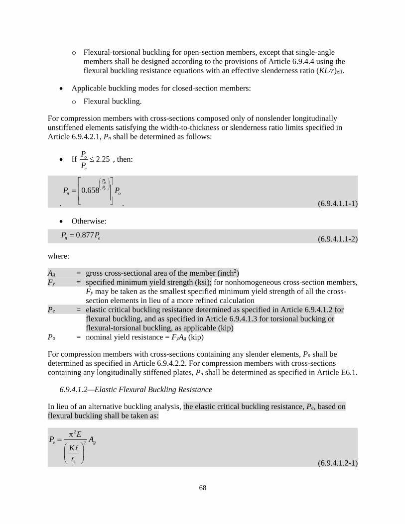
68
o Flexural-torsional buckling for open-section members, except that single-angle members shall be designed according to the provisions of Article 6.9.4.4 using the flexural buckling resistance equations with an effective slenderness ratio (KL/r)eff.
• Applicable buckling modes for closed-section members: o Flexural buckling.
For compression members with cross-sections composed only of nonslender longitudinally unstiffened elements satisfying the width-to-thickness or slenderness ratio limits specified in Article 6.9.4.2.1, Pn shall be determined as follows:
• If 2.25o
e
PP
≤ , then:
.
0.658o
e
PP
n oP P
= . (6.9.4.1.1-1)
• Otherwise:
0.877n eP P= (6.9.4.1.1-2)
where:
Ag = gross cross-sectional area of the member (inch2) Fy = specified minimum yield strength (ksi); for nonhomogeneous cross-section members,
Fy may be taken as the smallest specified minimum yield strength of all the cross-section elements in lieu of a more refined calculation
Pe = elastic critical buckling resistance determined as specified in Article 6.9.4.1.2 for flexural buckling, and as specified in Article 6.9.4.1.3 for torsional bucking or flexural-torsional buckling, as applicable (kip)
Po = nominal yield resistance = FyAg (kip)
For compression members with cross-sections containing any slender elements, Pn shall be determined as specified in Article 6.9.4.2.2. For compression members with cross-sections containing any longitudinally stiffened plates, Pn shall be determined as specified in Article E6.1.
6.9.4.1.2—Elastic Flexural Buckling Resistance
In lieu of an alternative buckling analysis, the elastic critical buckling resistance, Pe, based on flexural buckling shall be taken as:
2
2e g
s
EP AKr
π=
(6.9.4.1.2-1)
69
where:
Ag = gross cross-sectional area of the member (inch2) K = effective length factor in the plane of buckling determined as specified in Article
4.6.2.5 = unbraced length in the plane of buckling (inch) rs = radius of gyration about the axis normal to the plane of buckling (inch)
6.9.4.2—Effects of Local Buckling on Member Nominal Compressive Resistance
6.9.4.2.1—Classification of Cross-Section Elements
Longitudinally unstiffened cross-section elements satisfying the following limit shall be defined as nonslender under member axial compression:
rbt≤ λ (6.9.4.2.1-1)
where:
λr = corresponding width-to-thickness or slenderness ratio limit as specified in Table 6.9.4.2.1-1 (Table 17 and 18)
b = element width as specified in Table 6.9.4.2.1-1 (inch) t = element thickness (inch); for flanges of rolled channels, use the average thickness;
for HSS, the provisions of Article 6.12.1.2.4 shall apply.
Local buckling effects shall be neglected for nonslender longitudinally unstiffened cross-section elements. Otherwise, longitudinally unstiffened elements shall be defined as slender under member axial compression and local buckling effects shall be considered according to the provisions of Article 6.9.4.2.2. For longitudinally stiffened cross-section elements, the strength of the stiffener struts, including potential local buckling effects, shall be considered according to the provisions of Article E6.1.

70
Table 17. AASHTO LRFD Specification Table 6.9.4.2.1-1. Element Width-to-Thickness or Slenderness Ratio Limits and Element Widths for Axial
Compression.
Elements Supported along One Longitudinal Edge λr b
Stems of Rolled Tees 0.75
y
EF
• Full depth of tee
Flanges of Rolled I-, Tee, and Channel Sections; Plates Projecting from Rolled I-Sections; and Outstanding Legs of Double Angles in Continuous Contact 0.56
y
EF
• Half-flange width for rolled I- and tee sections • Full-flange width for channel sections • Distance between free edge and first line of bolts
or welds for plates projecting from rolled I-sections
• Full width of an outstanding leg for double angles in continuous contact
Flanges of Welded and Nonwelded Built-Up I-Sections 0.64 c
y
k EF
• Half-flange width for welded and nonwelded built-up I-sections
Outstanding Legs of Single Angles; Outstanding Legs of Double Angles with Separators; Flange Extensions of Box Sections; Plates or Angle Legs Projecting from Welded and Nonwelded Built-Up I- or Box Sections; and All Other Plates Supported along One Longitudinal Edge
0.45y
EF
• Full width of outstanding leg for single angle or double angles with separators
• Full projecting width for all others
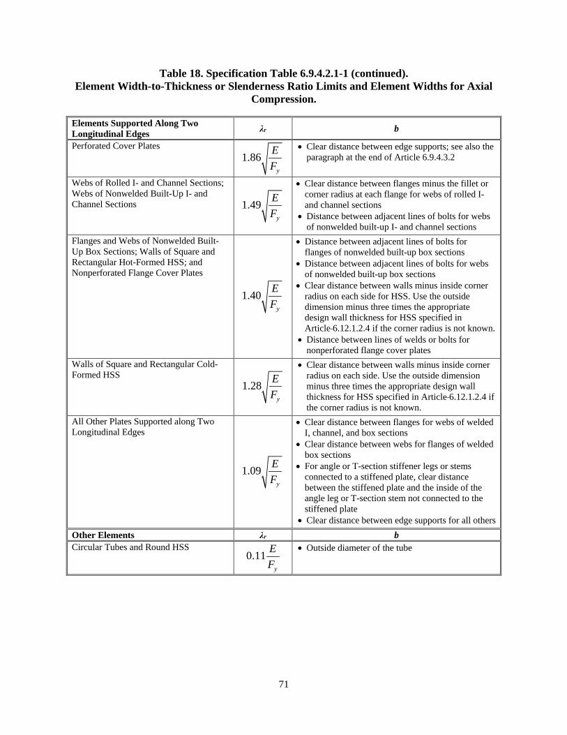
71
Table 18. Specification Table 6.9.4.2.1-1 (continued). Element Width-to-Thickness or Slenderness Ratio Limits and Element Widths for Axial
Compression.
Elements Supported Along Two Longitudinal Edges λr b
Perforated Cover Plates 1.86
y
EF
• Clear distance between edge supports; see also the
paragraph at the end of Article 6.9.4.3.2
Webs of Rolled I- and Channel Sections; Webs of Nonwelded Built-Up I- and Channel Sections 1.49
y
EF
• Clear distance between flanges minus the fillet or corner radius at each flange for webs of rolled I- and channel sections
• Distance between adjacent lines of bolts for webs of nonwelded built-up I- and channel sections
Flanges and Webs of Nonwelded Built-Up Box Sections; Walls of Square and Rectangular Hot-Formed HSS; and Nonperforated Flange Cover Plates
1.40y
EF
• Distance between adjacent lines of bolts for flanges of nonwelded built-up box sections
• Distance between adjacent lines of bolts for webs of nonwelded built-up box sections
• Clear distance between walls minus inside corner radius on each side for HSS. Use the outside dimension minus three times the appropriate design wall thickness for HSS specified in Article 6.12.1.2.4 if the corner radius is not known.
• Distance between lines of welds or bolts for nonperforated flange cover plates
Walls of Square and Rectangular Cold-Formed HSS
1.28y
EF
• Clear distance between walls minus inside corner radius on each side. Use the outside dimension minus three times the appropriate design wall thickness for HSS specified in Article 6.12.1.2.4 if the corner radius is not known.
All Other Plates Supported along Two Longitudinal Edges
1.09y
EF
• Clear distance between flanges for webs of welded I, channel, and box sections
• Clear distance between webs for flanges of welded box sections
• For angle or T-section stiffener legs or stems connected to a stiffened plate, clear distance between the stiffened plate and the inside of the angle leg or T-section stem not connected to the stiffened plate
• Clear distance between edge supports for all others Other Elements λr b Circular Tubes and Round HSS
0.11y
EF
• Outside diameter of the tube
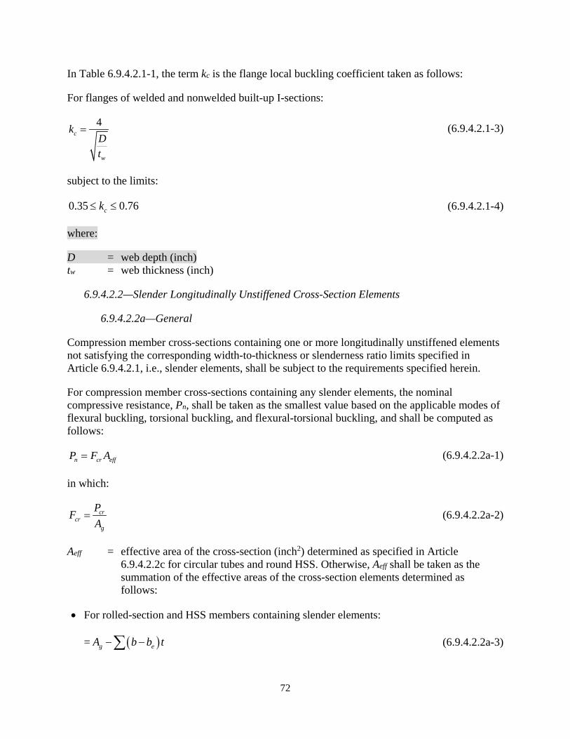
72
In Table 6.9.4.2.1-1, the term kc is the flange local buckling coefficient taken as follows:
For flanges of welded and nonwelded built-up I-sections:
4c
w
kDt
= (6.9.4.2.1-3)
subject to the limits:
0.35 0.76ck≤ ≤ (6.9.4.2.1-4)
where:
D = web depth (inch) tw = web thickness (inch)
6.9.4.2.2—Slender Longitudinally Unstiffened Cross-Section Elements
6.9.4.2.2a—General
Compression member cross-sections containing one or more longitudinally unstiffened elements not satisfying the corresponding width-to-thickness or slenderness ratio limits specified in Article 6.9.4.2.1, i.e., slender elements, shall be subject to the requirements specified herein.
For compression member cross-sections containing any slender elements, the nominal compressive resistance, Pn, shall be taken as the smallest value based on the applicable modes of flexural buckling, torsional buckling, and flexural-torsional buckling, and shall be computed as follows:
n cr effP F A= (6.9.4.2.2a-1)
in which:
crcr
g
PFA
= (6.9.4.2.2a-2)
Aeff = effective area of the cross-section (inch2) determined as specified in Article 6.9.4.2.2c for circular tubes and round HSS. Otherwise, Aeff shall be taken as the summation of the effective areas of the cross-section elements determined as follows:
• For rolled-section and HSS members containing slender elements:
= ( )g eA b b t− −∑ (6.9.4.2.2a-3)
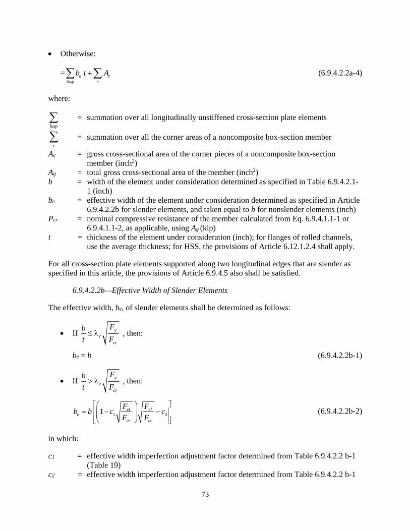
73
• Otherwise:
= e clusp c
b t A+∑ ∑ (6.9.4.2.2a-4)
where:
lusp∑ = summation over all longitudinally unstiffened cross-section plate elements
c∑ = summation over all the corner areas of a noncomposite box-section member
Ac = gross cross-sectional area of the corner pieces of a noncomposite box-section member (inch2)
Ag = total gross cross-sectional area of the member (inch2) b = width of the element under consideration determined as specified in Table 6.9.4.2.1-
1 (inch) be = effective width of the element under consideration determined as specified in Article
6.9.4.2.2b for slender elements, and taken equal to b for nonslender elements (inch) Pcr = nominal compressive resistance of the member calculated from Eq. 6.9.4.1.1-1 or
6.9.4.1.1-2, as applicable, using Ag (kip) t = thickness of the element under consideration (inch); for flanges of rolled channels,
use the average thickness; for HSS, the provisions of Article 6.12.1.2.4 shall apply.
For all cross-section plate elements supported along two longitudinal edges that are slender as specified in this article, the provisions of Article 6.9.4.5 also shall be satisfied.
6.9.4.2.2b—Effective Width of Slender Elements
The effective width, be, of slender elements shall be determined as follows:
• If yr
cr
Fbt F≤ λ , then:
be = b (6.9.4.2.2b-1)
• If yr
cr
Fbt F> λ , then:
1 31 el ele
cr cr
F Fb b c cF F
= − −
(6.9.4.2.2b-2)
in which:
c1 = effective width imperfection adjustment factor determined from Table 6.9.4.2.2 b-1 (Table 19)
c2 = effective width imperfection adjustment factor determined from Table 6.9.4.2.2 b-1
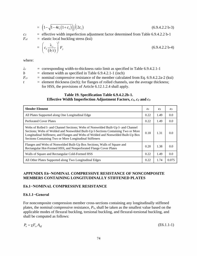
74
= ( )( ) ( )1 3 11 1 4 1 2c c c− − + (6.9.4.2.2 b-3)
c3 = effective width imperfection adjustment factor determined from Table 6.9.4.2.2 b-1 Fel = elastic local buckling stress (ksi)
= ( )
2
2r
yc Fb t
λ
(6.9.4.2.2 b-4)
where:
λr = corresponding width-to-thickness ratio limit as specified in Table 6.9.4.2.1-1 b = element width as specified in Table 6.9.4.2.1-1 (inch) Fcr = nominal compressive resistance of the member calculated from Eq. 6.9.4.2.2a-2 (ksi) t = element thickness (inch); for flanges of rolled channels, use the average thickness;
for HSS, the provisions of Article 6.12.1.2.4 shall apply.
Table 19. Specification Table 6.9.4.2.2b-1. Effective Width Imperfection Adjustment Factors, c1, c2 and c3
Slender Element c1 c2 c3
All Plates Supported along One Longitudinal Edge 0.22 1.49 0.0
Perforated Cover Plates 0.22 1.49 0.0
Webs of Rolled I- and Channel Sections; Webs of Nonwelded Built-Up I- and Channel Sections; Webs of Welded and Nonwelded Built-Up I-Sections Containing Two or More Longitudinal Stiffeners; and Flanges and Webs of Welded and Nonwelded Built-Up Box Sections Containing Two or More Longitudinal Stiffeners
0.18 1.31 0.0
Flanges and Webs of Nonwelded Built-Up Box Sections; Walls of Square and Rectangular Hot-Formed HSS; and Nonperforated Flange Cover Plates 0.20 1.38 0.0
Walls of Square and Rectangular Cold-Formed HSS 0.22 1.49 0.0
All Other Plates Supported along Two Longitudinal Edges 0.22 1.74 0.075
APPENDIX E6−NOMINAL COMPRESSIVE RESISTANCE OF NONCOMPOSITE MEMBERS CONTAINING LONGITUDINALLY STIFFENED PLATES
E6.1−NOMINAL COMPRESSIVE RESISTANCE
E6.1.1−General
For noncomposite compression member cross-sections containing any longitudinally stiffened plates, the nominal compressive resistance, Pn, shall be taken as the smallest value based on the applicable modes of flexural buckling, torsional buckling, and flexural-torsional buckling, and shall be computed as follows:
n cr effP F A= χ (E6.1.1-1)
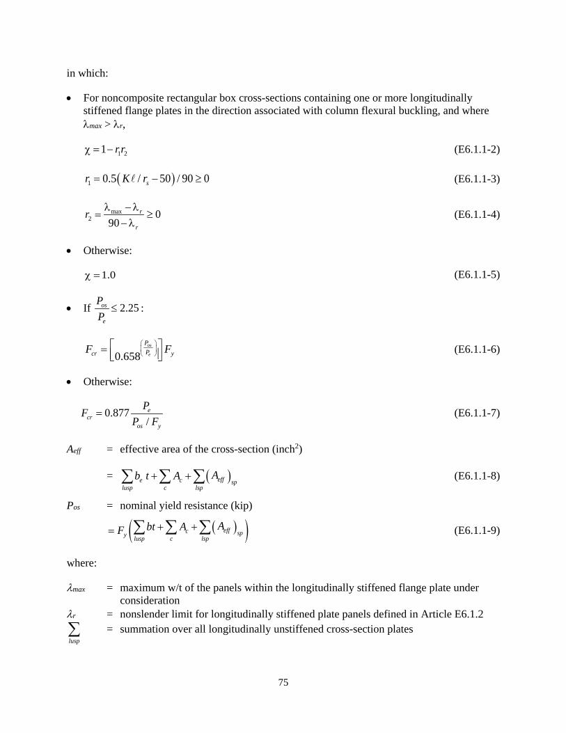
75
in which:
• For noncomposite rectangular box cross-sections containing one or more longitudinally stiffened flange plates in the direction associated with column flexural buckling, and where λmax > λr,
1 21 r rχ = − (E6.1.1-2)
( )1 0.5 / 50 / 90 0sr K r= − ≥ (E6.1.1-3)
max2 0
90r
r
r λ −λ= ≥
−λ (E6.1.1-4)
• Otherwise:
1.0χ = (E6.1.1-5)
• If 2.25os
e
PP
≤ :
0.658os
e
PPcr yF F
= (E6.1.1-6)
• Otherwise:
0.877/e
cros y
PFP F
= (E6.1.1-7)
Aeff = effective area of the cross-section (inch2)
= ( )effe c splusp c lsp
Ab t A+ +∑ ∑ ∑ (E6.1.1-8)
Pos = nominal yield resistance (kip)
( )( )effc spy lusp c lsp
Abt AF + += ∑ ∑ ∑ (E6.1.1-9)
where:
λmax = maximum w/t of the panels within the longitudinally stiffened flange plate under consideration
λr = nonslender limit for longitudinally stiffened plate panels defined in Article E6.1.2
lusp∑ = summation over all longitudinally unstiffened cross-section plates
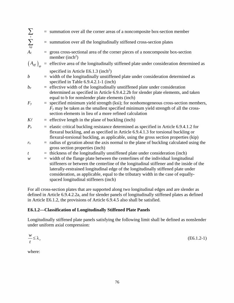
76
c∑ = summation over all the corner areas of a noncomposite box-section member
lsp∑ = summation over all the longitudinally stiffened cross-section plates
Ac = gross cross-sectional area of the corner pieces of a noncomposite box-section member (inch2)
( )eff spA = effective area of the longitudinally stiffened plate under consideration determined as
specified in Article E6.1.3 (inch2) b = width of the longitudinally unstiffened plate under consideration determined as
specified in Table 6.9.4.2.1-1 (inch) be = effective width of the longitudinally unstiffened plate under consideration
determined as specified in Article 6.9.4.2.2b for slender plate elements, and taken equal to b for nonslender plate elements (inch)
Fy = specified minimum yield strength (ksi); for nonhomogeneous cross-section members, Fy may be taken as the smallest specified minimum yield strength of all the cross-section elements in lieu of a more refined calculation
K = effective length in the plane of buckling (inch) Pe = elastic critical buckling resistance determined as specified in Article 6.9.4.1.2 for
flexural buckling, and as specified in Article 6.9.4.1.3 for torsional buckling or flexural-torsional buckling, as applicable, using the gross section properties (kip)
rs = radius of gyration about the axis normal to the plane of buckling calculated using the gross section properties (inch)
t = thickness of the longitudinally unstiffened plate under consideration (inch) w = width of the flange plate between the centerlines of the individual longitudinal
stiffeners or between the centerline of the longitudinal stiffener and the inside of the laterally-restrained longitudinal edge of the longitudinally stiffened plate under consideration, as applicable, equal to the tributary width in the case of equally-spaced longitudinal stiffeners (inch)
For all cross-section plates that are supported along two longitudinal edges and are slender as defined in Article 6.9.4.2.2a, and for slender panels of longitudinally stiffened plates as defined in Article E6.1.2, the provisions of Article 6.9.4.5 also shall be satisfied.
E6.1.2—Classification of Longitudinally Stiffened Plate Panels
Longitudinally stiffened plate panels satisfying the following limit shall be defined as nonslender under uniform axial compression:
rwt≤ λ (E6.1.2-1)
where:
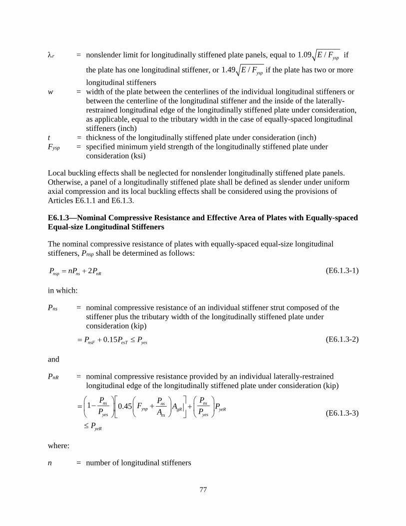
77
λr = nonslender limit for longitudinally stiffened plate panels, equal to 1.09 / yspE F if
the plate has one longitudinal stiffener, or 1.49 / yspE F if the plate has two or more longitudinal stiffeners
w = width of the plate between the centerlines of the individual longitudinal stiffeners or between the centerline of the longitudinal stiffener and the inside of the laterally-restrained longitudinal edge of the longitudinally stiffened plate under consideration, as applicable, equal to the tributary width in the case of equally-spaced longitudinal stiffeners (inch)
t = thickness of the longitudinally stiffened plate under consideration (inch) Fysp = specified minimum yield strength of the longitudinally stiffened plate under
consideration (ksi)
Local buckling effects shall be neglected for nonslender longitudinally stiffened plate panels. Otherwise, a panel of a longitudinally stiffened plate shall be defined as slender under uniform axial compression and its local buckling effects shall be considered using the provisions of Articles E6.1.1 and E6.1.3.
E6.1.3—Nominal Compressive Resistance and Effective Area of Plates with Equally-spaced Equal-size Longitudinal Stiffeners
The nominal compressive resistance of plates with equally-spaced equal-size longitudinal stiffeners, Pnsp shall be determined as follows:
2nsp ns nRP nP P= + (E6.1.3-1)
in which:
Pns = nominal compressive resistance of an individual stiffener strut composed of the stiffener plus the tributary width of the longitudinally stiffened plate under consideration (kip)
0.15nsF esT yesP P P= + ≤ (E6.1.3-2)
and
PnR = nominal compressive resistance provided by an individual laterally-restrained longitudinal edge of the longitudinally stiffened plate under consideration (kip)
1 0.45ns nsns
ysp gR yeRyes yeses
yeR
P PPF A PP PA
P
− += +
≤
(E6.1.3-3)
where:
n = number of longitudinal stiffeners

78
The following terms apply to the calculation of Pns:
nsFP = nominal flexural buckling resistance of an individual stiffener strut (kip) determined as follows:
• If 2.25ys
esF
PP
≤ , then:
0.658ys
esF
PP
nsF yesP P= (E6.1.3-4)
• Otherwise:
0.877 esFnsF es
gs
PP AA
= (E6.1.3-5)
esFP = elastic flexural buckling resistance of an individual stiffener strut (kip)
22
22 4
ps
sp
EwIEIb
ππ= +
(E6.1.3-6)
Ip = lateral moment of inertia of a unit width of the longitudinally stiffened plate under consideration (inch3)
( )
3
212 1spt
=−ν
(E6.1.3-7)
= buckling length of the individual stiffener struts, taken equal to the smaller of a and
c (inch), where:
• a = longitudinal spacing between locations of transverse stiffeners or diaphragms that provide transverse lateral restraint to the longitudinally stiffened plate under consideration (inch)
• c = characteristic buckling length of the stiffener struts of the longitudinally stiffened plate under consideration (inch)
1/4s
spp
IbwI
=
(E6.1.3-8)
Aes = effective area of an individual stiffener strut (inch2)
s e spA w t= + (E6.1.3-9)
Ags = gross area of an individual stiffener strut (inch2)
s spA wt= + (E6.1.3-10) PesT = plate torsional stiffness contribution to the elastic buckling resistance of an
individual stiffener strut (kip)

79
( )
32
2 31sp
sp
Gwtb
π=
−ν (E6.1.3-11)
Pyes = effective yield load of an individual stiffener strut (kip)
ysp esF A= (E6.1.3-12)
Pys = yield load of an individual stiffener strut (kip)
ysp gsF A= (E6.1.3-13)
where:
ν = Poisson’s ratio = 0.3 As = gross area of an individual longitudinal stiffener, excluding the tributary width of the
longitudinally stiffened plate under consideration (inch2) bsp = total width of the longitudinally stiffened plate, taken as the inside distance between
the plates providing lateral restraint to its longitudinal edges (inch) Fysp = specified minimum yield strength of the longitudinally stiffened plate under
consideration (ksi) G = shear modulus of elasticity for steel = 0.385E (ksi) Is = moment of inertia of an individual stiffener strut composed of the stiffener plus the
gross tributary width, w, of the longitudinally stiffened plate under consideration, taken about an axis parallel to the face of the longitudinally stiffened plate and passing through the centroid of the combined area of the longitudinal stiffener and its gross tributary plate width (inch4)
tsp = thickness of the longitudinally stiffened plate under consideration (inch) w = width of the plate between the centerlines of the individual longitudinal stiffeners or
between the centerline of the longitudinal stiffener and the inside of the laterally-restrained longitudinal edge of the longitudinally stiffened plate under consideration, as applicable, equal to the gross tributary width in the case of equally-spaced longitudinal stiffeners (inch)
we = effective width of the plate tributary to each stiffener strut, taken as the corresponding value of be calculated as specified in Article 6.9.4.2.2b with w substituted for b, with Fcr taken as Fysp and with λr taken as specified in Article E6.1.2 (inch)
The following additional terms apply to the calculation of PnR:
AgR = gross tributary area of the laterally-restrained longitudinal edge of the longitudinally stiffened plate under consideration (inch2)
2 spw t= (E6.1.3-14)
PyeR = effective yield load of an individual laterally-restrained longitudinal edge of the longitudinally stiffened plate under consideration (kip)
ysp eRF A= (E6.1.3-15)
80
AeR = effective tributary area of the laterally-restrained longitudinal edge of the longitudinally stiffened plate under consideration (inch2)
2
esp
w t= (E6.1.3-16)
The longitudinal stiffeners shall satisfy the requirements of Article E6.1.4. Transverse stiffeners, when utilized to strengthen or stiffen a longitudinally stiffened plate, shall satisfy the requirements of Article E6.1.5.
The effective area of plates with equally-spaced equal-size longitudinal stiffeners shall be calculated as follows:
( ) nspeff sp
ysp
PA
F= (E6.1.3-17)
E6.1.4—Longitudinal Stiffener Requirements
Longitudinal stiffeners should consist of a flat rectangular plate, a rib, an angle, or a tee-section welded to one side of the plate. The specified minimum yield strength of the stiffeners should not be less than the specified minimum yield strength of the plate to which they are attached.
Longitudinal stiffeners shall be structurally continuous over their specified length, and should be continuously welded to the plate.
The cross-section elements of longitudinal stiffeners should satisfy:
rbt≤ λ (E6.1.4-1)
where:
λr = corresponding width-to-thickness ratio limit for the longitudinal stiffener plate element under consideration as specified in Table 6.9.4.2.1-1
b = longitudinal stiffener plate element width as specified in Table 6.9.4.2.1-1 (inch) t = longitudinal stiffener plate element thickness (inch)
In addition, tee and angle section longitudinal stiffeners should satisfy:
5.0 ys
ps
FJI E
≥ (E6.1.4-2)
where:
Fy = specified minimum yield strength of the longitudinally stiffened plate element under consideration (ksi)
81
Js = St. Venant torsional constant of the longitudinal stiffener alone, not including the contribution from the stiffened plate (inch4)
Ips = polar moment of inertia of the longitudinal stiffener alone about the attached edge (inch4)
Longitudinal stiffeners on flanges with bsp/tsp > 90 generally shall satisfy:
/ 120sa r ≤ (E6.1.4-3)
in which:
rs = radius of gyration of the stiffener strut about an axis parallel to the plane of the stiffened plate (inch)
= s gsI A (E6.1.4-4)
where:
a = longitudinal spacing between locations of transverse stiffeners or diaphragms that provide transverse lateral restraint to the longitudinally stiffened plate under consideration (inch)
bsp = total width of the longitudinally stiffened plate, taken as the inside distance between the plates providing lateral restraint to its longitudinal edges (in.)
Ags = gross area of an individual stiffener strut as defined in Article E6.1.3 (inch2) Is = moment of inertia of an individual stiffener strut as defined in Article E6.1.3 (inch4) tsp = thickness of the longitudinally stiffened plate under consideration (inch)
E6.1.5—Transverse Stiffener Requirements
E6.1.5.1−General
Transverse stiffeners provided to enhance the resistance of a longitudinally stiffened plate should consist of a flat rectangular plate or a tee-section continuously welded to one side of the stiffened plate, or a top or bottom strut of an internal cross-frame or a wide-flange section placed across the outstanding end of the longitudinal stiffeners.
With the exception of longitudinally stiffened plates containing transverse stiffeners in which:
• the characteristic length, c, from Eq. E6.1.3-8 is less than the spacing, a, defined in Article E6.1.3, and;
• the transverse stiffeners are not subjected to any directly applied bending or axial compression,
transverse stiffeners used to increase the compressive resistance of a longitudinally stiffened plate shall satisfy the moment of inertia requirements specified in Article E6.1.5.2.
82
Transverse stiffeners generally should have a moment of inertia, It, defined in Article E6.1.5.2 greater than or equal to the moment of inertia that of the longitudinal stiffeners, Is, defined in Article E6.1.3.
The cross-section elements of transverse stiffeners also should satisfy the requirements of Eqs. E6.1.4-1 and E6.1.4-2.
Longitudinal stiffeners shall be structurally continuous at transverse stiffeners. Transverse stiffeners also shall be structurally continuous and attached at their ends to the plates providing lateral restraint to the edge of the longitudinally stiffened plate under consideration.
E6.1.5.2−Moment of Inertia
Transverse stiffeners that are:
• Used to strengthen a longitudinally stiffened plate, and,
• Are not subjected to a concentrically applied axial compressive force and/or directly applied loads causing bending of the stiffener
shall satisfy the following moment of inertia requirements:
3
min
0.05 up spt
P bI
a E≥ (E6.1.5.2-1)
and
3
min
0.0009 0.02 up spt
y sp
P bE cIF b a E
≥ +
(E6.1.5.2-2)
where:
amin = smallest of the longitudinal spacings to the adjacent transverse stiffeners or diaphragms providing lateral restraint to the plate (inch)
c = largest distance from the neutral axis to the extreme fiber of the transverse stiffener considered in the calculation of It (inch)
bsp = total inside width between the plate elements providing lateral restraint to the longitudinal edges of the plate under consideration (inch)
Fy = smallest specified minimum yield strength of the stiffened plate and the transverse stiffener under consideration (ksi)
It = moment of inertia of the transverse stiffener, including a width of the stiffened plate equal to 9tsp, but not more than the actual dimension available, on each side of the stiffener avoiding any overlap with contributing parts to adjacent stiffeners or diaphragms, taken about the centroidal axis of the combined section. The reduced cross-section at cutouts to accommodate longitudinal stiffeners shall be considered; the smallest moment of inertia at such cutouts shall be used for It (inch4)
83
Pup = total factored longitudinal compression force in the plate under consideration, determined from a structural analysis considering the gross cross-section, including the longitudinal stiffeners, and including all sources of factored longitudinal normal compressive stresses from axial loading and from flexure; in cases where the plate is subjected to longitudinal normal stresses in tension over a portion of its width, the tensile stresses shall be neglected in determining this force (kip)
tsp = thickness of the stiffened plate (inch)
3.1.2. Discussion
3.1.2.1. Member Nominal Compressive Resistance, General Requirements (Article 6.9.4.1.1)
Equations 6.9.4.1.1-1 and 6.9.4.1.1-2 are equivalent to the corresponding axial compressive resistance equations given in AISC (2016). These baseline equations are applicable for cross-sections without any longitudinal stiffeners and in which all the component elements satisfy the
The equations are written in terms of the critical elastic buckling resistance, Pe, and the equivalent nominal yield resistance, Po, to facilitate the calculation of the nominal resistance for members subject to buckling modes in addition to, or other than, flexural buckling. Also, this form of the resistance equations may be used to conveniently calculate Pn when a refined buckling analysis is employed to assess the stability of trusses, frames or arches in lieu of utilizing an effective length factor approach (White, 2012). In such cases, Pe in Equations 6.9.4.1.1-1 and 6.9.4.1.1-2 would be taken as the axial load in a given member taken from the analysis at incipient elastic buckling of the structure or subassemblage.
corresponding width-to-thickness or slenderness ratio limits specified in Article 6.9.4.2.1.
Equations 6.9.4.1.1-1 and 6.9.4.1.1-2 are approximately the same as column strength curve 2P of Ziemian (2010). These equations are based on a mean out-of-straightness of L/1500. The development of the mathematical form of these equations is described in Tide (1985), and the structural reliability they are intended to provide in the context of building design applications is discussed in Galambos (2006). Due to the large torsional stiffness of closed-section members, the reduction in the resistance due to the influence of torsional buckling deformations is small. Therefore, only flexural buckling is considered for closed-section members.
For compression members with cross-sections containing any slender elements, i.e., cross-sections containing one or more longitudinally unstiffened elements not satisfying the corresponding width-to-thickness or slenderness ratio limits specified in Article 6.9.4.2.1, Pn is instead to be determined according to the provisions of Article 6.9.4.2.2 to account for the effect of potential local buckling of those elements on the overall buckling resistance of the member. For longitudinally stiffened plates, the effects of the longitudinal stiffeners and their tributary plate width acting as stiffener struts, as well as the potential local buckling of the individual stiffened plate panels, are addressed directly in Article E6.1.3.
For nonhomogeneous cross-section members, this article specifies conservatively that Fy may be taken as the smallest specified minimum yield strength of all the cross-section elements for the calculation of Po. For doubly symmetric I- and box-section profiles, Equations 6.9.4.1.1-1 and 6.9.4.1.1-2 are considered applicable when Fywmin is between 0.7 and 1.0 times Fyfmin and with Po calculated as follows:

84
min mino yf f yw wflanges webs
P F A F A= +∑ ∑ (28)
where:
Af = gross area of an individual flange element (inch2) Aw = gross area of an individual web element (inch2) Fyfmin = smallest value of the individual flange element specified minimum yield strengths
(ksi) Fywmin = smallest value of the individual web element specified minimum yield strengths (ksi)
Equations 6.9.4.1.1-1 and 6.9.4.1.1-2 with this modification are not directly applicable for members in which the corresponding resultant of the yield load, Po, is shifted significantly relative to the elastic centroidal axis of the cross-section
For bearing stiffeners, only the limit state of flexural buckling is applicable. In addition, given the width-to-thickness ratio limits for bearing stiffener cross-section elements specified by Article 6.10.11.2.2 and 6.10.11.2.4b, bearing stiffeners are effectively composed only of nonslender elements. The contribution of a thin web to the bearing stiffener axial compressive resistance is accounted for within the effective section provisions of Article 6.10.11.2.4b. As such, Article 6.9.4.1.1 is applicable for calculating the axial compressive resistance of bearing stiffeners.
The need for consideration of local buckling of slender plate elements via Article 6.9.4.2.2, and the need for consideration of longitudinal stiffeners and their tributary plate width acting as stiffener struts as well as the potential local buckling of the individual stiffened plate panels via Article E6.1, is avoided by using longitudinally unstiffened plates satisfying the requirement of Equation 6.9.4.2.1-1. This equation references the nonslender longitudinally unstiffened plate limits specified in Table 6.9.4.2.1-1.
In some cases, it may be more economical to use members having one or more slender plates in which the strength is reduced due to local buckling effects. For instance, rolled wide-flange sections with ratios of d/bf ≥ 1.7, where d is the section depth and bf is the flange width, typically have slender webs for uniform axial compression. Webs of welded I- and box sections also typically are classified as slender elements for axial compression according to Equation 6.4.4.2.1-1. Flanges of welded box-section members subject to bending and axial compression may be slender with respect to the axial compressive resistance in regions of low bending moment, since less plate thickness is needed to resist the axial force plus bending in these regions for a given plate width. The stems of a significant number of rolled tee sections and one or both legs of many rolled angle sections are also classified as slender elements. Furthermore, a large number of square or rectangular HSS profiles have slender wall elements corresponding to a member subjected to axial compression.
Section 3.1.2.8 discusses cases where it may or may not be beneficial to consider longitudinal stiffening of cross-section plate elements.
85
Flowcharts illustrating the application of the provisions of Article 6.9.4 for determining the compressive resistance of noncomposite I- or box-section members, with or without longitudinally stiffened plates, are provided in Appendix A.
3.1.2.2. Member Nominal Compressive Resistance, Elastic Buckling Resistance (Article 6.9.4.1.2)
Flexural buckling of concentrically loaded compression members refers to a buckling mode in which the member deflects laterally without twist or a change in the cross-sectional shape. Flexural buckling involves lateral displacements of the member cross-sections in the direction perpendicular to the x- or y-axes that are resisted by the flexural rigidities, EIx or EIy, of the member, respectively.
Equation 6.9.4.1.2-1 should be used to calculate the critical flexural buckling resistances about the x- and y-axes, with the smaller value taken as Pe for use in Equation 6.9.4.1.1-1 or 6.9.4.1.1-2, as applicable.
Because of their large GJ, torsional buckling and flexural-torsional buckling need not be considered for closed sections, including built-up members connected by lacing bars, batten plates, perforated plates, or any combination thereof.
3.1.2.3. Effects of Local Buckling on Member Nominal Compressive Resistance, Classification of Cross-Section Elements (Article 6.9.4.2.1)
Compression members with cross-sections composed only of nonslender longitudinally unstiffened elements, i.e., cross-sections without any longitudinal stiffeners in which all the component elements satisfy the corresponding width-to-thickness or slenderness ratio limits specified in Article 6.9.4.2.1, are able to develop their full yield strength under uniform axial compression without any significant impact from local buckling. For compression members with cross-sections containing any slender elements, i.e., longitudinally unstiffened elements not satisfying the corresponding width-to-thickness or slenderness ratio limits specified in Article 6.9.4.2.1, the nominal compressive resistance is instead to be determined according to the provisions of Article 6.9.4.2.2 to account for the effect of potential local buckling of those cross-section elements on the overall compressive resistance of the member. For longitudinally stiffened plates, the effects of local buckling of the individual panels are addressed in Article E6.1.3.
The following is a detailed discussion of the background to the AASHTO nonslender element limits.
The width-to-thickness or slenderness ratio limits specified in Article 6.9.4.2.1 do not apply when determining the resistance of flexural members for which the compression flange and web elements may need to withstand larger inelastic strains in order to ensure that local buckling does not adversely affect the calculated resistance. For such cases, the more stringent width-to-thickness or slenderness requirements of the applicable portions of Articles 6.10, 6.11 and 6.12 apply.

86
The nonslender width-to-thickness limits are derived from the classical elastic critical stress formula for plates:
( )( )
2
2212 /1c
crk EF
b tπ
=−ν
(29)
in which the buckling coefficient, kc, is a function of loading and support conditions. For a long, uniformly compressed plate with one longitudinal edge simply-supported against rotation and the other free, kc = 0.425, and for both edges simply-supported, kc = 4.0 (Timoshenko and Gere, 1961). For these conditions, the coefficients of the b/t equation become 0.42 and 1.28, respectively. The coefficients specified in Article 6.9.4.2.1 are the result of further analyses and numerous tests and reflect the effect of residual stresses, initial imperfections, and actual, as opposed to ideal, support conditions. In all cases, the coefficients on the nonslender plate limits may be calculated as 20.951 / ,ck c where c2 is the effective width imperfection adjustment factor determined from Table 6.9.4.2.2a-1 (White and Lokhande, 2017).
For projecting flanges of built-up I-sections under axial compression, web-flange interaction is considered. Theory indicates that the web-flange interaction for built-up I-sections under axial compression is at least as severe as for flexure. The kc factor accounts for the interaction of flange and web local buckling demonstrated in experiments conducted by Johnson (1985). For built-up sections with D/tw ≥ 130.6, kc may be taken equal to 0.35. For smaller values of D/tw, kc increases from 0.35 up to a maximum value of 0.76 as a function of the web slenderness D/tw. A kc value of 0.76 yields a coefficient of 0.56 in the width-to-thickness ratio limit. Rolled I-sections are excluded from this criterion because web-flange interaction effects are considered negligible for these sections.
The width-to-thickness limit for perforated cover plates reflects the effective influence of the edge and geometry conditions on these plates, and is consistent with past practice in the AASHTO LRFD Specifications.
The width-to-thickness limit for flanges and webs of nonwelded built-up box-sections, walls of square and rectangular hot-formed HSS, and nonperforated flange cover plates recognizes the tendency for smaller local buckling strength reductions due to the geometric imperfection, residual stress and edge restraint effects in these elements. The coefficient of 1.40 on this nonslender plate limit corresponds to an implicit kc of 4.13 given c2 = 1.38 as specified in Table 6.9.4.2.2a-1. There is evidence that this limit is somewhat larger than is representative of cold-formed HSS and general welded sections (White and Lokhande, 2017).
The width-to-thickness limit for webs of rolled I- and channel sections and webs of nonwelded built-up I- and channel sections is based on original efforts documented in AISC (1969) to obtain a better fit to test results for cases “where appreciable torsional restraint is provided, as for example the web of an I-shaped column.” This idealization produces the values c1 = 0.18 and c2 = 1.31 in Table 6.9.4.2.2a-1. The coefficient of 1.49 on this nonslender plate limit corresponds to an implicit kc of 4.22. This limit is also employed in the recommended Appendix E6.1.2 for the panels of plates containing two or more longitudinal stiffeners. These types of plates have additional local buckling resistance compared to plates without longitudinal stiffeners, or with
87
only one longitudinal stiffener, due to the lateral restraint from the adjacent panels at the longitudinal stiffener locations. Plates with one longitudinal stiffener have a smaller increase in their local buckling resistance due to this effect; this strength increase is neglected in Appendix E6.1.2 to simplify the strength calculations.
The width-to-thickness limit for walls of square and rectangular cold-formed HSS corresponds to the limit employed in AISI (2016) for the design of cold-formed steel structural members. The coefficient of 1.28 on this nonslender plate limit corresponds to an implicit kc of 4.00.
Lastly, the width-to-thickness limit for webs of welded I- and channel sections, flanges and webs of welded built-up box-sections, and all other plates supported along two longitudinal edges, is based on recent research on welded box-sections and synthesis of a wide range of prior research on members composed of general welded plate assemblies (White and Lokhande, 2017). The coefficient of 1.09 on this nonslender plate limit is consistent with the values of c1 = 0.22, c2 = 1.74 and c3 = 0.075 specified in Table 6.9.4.2.2a-1. This coefficient corresponds to an implicit kc of 4.00. The smaller coefficient in the nonslender limit for these cases recognizes the influence of welding residual stresses as well as the typical small amount of lateral restraint at the plate edges from adjacent cross-section plate elements that are oriented at a significant angle relative to the plate under consideration.
The local buckling resistance of circular tubes, including round Hollow Structural Sections (HSS), is significantly overestimated by the classical theory for longitudinally compressed cylinders due to imperfections of shape and eccentricities of the load. Therefore, the limit given in Table 6.9.4.2.1-1 to prevent local buckling of circular tubes is based on test results (Sherman, 1976) rather than theoretical calculations. When D/t exceeds the value given in Table 6.9.4.2.1-1, the provisions of Article 6.9.4.2.2b should be used to compute the effective area of the tube. The provisions of Article 6.9.4.2.2b are valid up to a D/t limit of 0.45E/Fy. Circular tubes with D/t values greater than this limit are not recommended for use as compression members.
3.1.2.4. Effects of Local Buckling on Member Nominal Compressive Resistance, Slender Longitudinally Unstiffened Cross-Section Elements, General (Article 6.9.4.2.2a)
For compression members containing any slender longitudinally unstiffened cross-section elements, buckling of the component elements may adversely affect the overall buckling resistance of the member. Hence, the nominal compressive resistance, Pn, based on flexural, torsional or flexural-torsional buckling, as applicable, may be reduced. For such members, Pn is determined using a generalized form of the unified effective width/unified effective area approach (AISC, 2016; AISI, 2016). Previous specifications utilized a dual philosophy for longitudinally unstiffened plates, commonly referred to as the Q factor method, in which slender elements supported on only one longitudinal edge were assumed to reach their limit of resistance when they attained their theoretical local buckling stress, while slender elements supported on both longitudinal edges utilized an effective width concept to obtain their post-buckling resistance. The unified effective width/unified effective area approach considers the effective width of both of these types of cross-section plate elements. This simplifies the resulting calculations and tends to provide a more accurate characterization of the ultimate strength of all types of slender longitudinally unstiffened plates that recognizes plate postbuckling resistance in

88
all cases. The development and basis of the unified approach is discussed in more detail in the Commentary to Section E7 of AISC (2016) and in Ziemian (2010).
Two equations are provided for the cross-section effective area to be used in the unified effective width/unified effective area approach. Equation 6.9.4.2.2a-3 facilitates the inclusion of the fillet areas in rolled-section and square or rectangular HSS members containing any slender elements. Equation 6.9.4.2.2a-4 addresses general welded and nonwelded built-up sections containing any slender plate elements. The second term of Equation 6.9.4.2.2a-4 represents the sum of the gross cross-sectional areas of the four corner pieces of a noncomposite box-section member not included in the clear width of the component plates; for all other members, Ac is taken as zero. Flange extensions on box-section members, if present, should be evaluated to determine if they are nonslender or slender elements and included accordingly in Equation 6.9.4.2.2a-4.
Equations 6.9.4.2.2a-1 through 6.9.4.2.2a-4 capture the influence of buckling of individual longitudinally unstiffened plates on the overall member axial compressive resistance in a simple yet accurate to conservative manner. Sections 2.2.1.1 and 2.2.1.2 compare this approach to related procedures in AISI (2016) and CEN (2006b) and to the results from tests and test simulations. The original development of the unified effective width/unified effective area method (Peköz, 1986) showed that accurate predictions were obtained for general singly-symmetric and unsymmetric beam-columns, with the exception of slender angle sections, when the moment of the axial loads is taken about the centroidal axis of the effective section determined considering axial load alone. AISI (2016) relaxes the requirement that the bending moment should be defined with respect to the centroidal axis of the effective section. The increased eccentricity due to local buckling can have a measurable impact on the resistance of an ideally pin-ended member; however, this effect tends to become minor in continuous members or members with ends restrained, where the rotations due to these eccentricities are restrained. AISC (2016) also neglects these effects. .
3.1.2.5. Effects of Local Buckling on Member Nominal Compressive Resistance, Slender Longitudinally Unstiffened Cross-Section Elements, Effective Width of Slender Elements (Article 6.9.4.2.2b)
Compression member cross-section elements are defined as slender when full yielding of the gross cross-section cannot be developed prior to local buckling impacting the resistance. However, if the stress level at overall member buckling, Fcr, is small enough relative to Fy, a slender cross-section element will not exhibit any significant local buckling effects prior to the member reaching its axial compressive resistance. This behavioral attribute is accounted for by checking the element width-to-thickness ratio, b/t, versus the modified limit .r y crF Fλ If b/t is
smaller than ,r y crF Fλ no significant local buckling effects occur prior to the member reaching its axial compressive resistance. In these cases, the effective width of the slender cross-section element is equal to the full element width as specified by Equation 6.9.4.2.2b-1.
Equation 6.9.4.2.2b-2 is a generalized form of the classical equation for plate local buckling effective widths implemented originally in the AISI (1986) cold-formed steel specifications and developed in the seminal work by Winter (1970). For a plate with ideal simply-supported edge conditions, where the theoretical plate local buckling coefficient kc = 4.0, the coefficients in

89
Winter’s equation for the plate effective width are c1 = 0.22, c2 = 1.485, and c3 = 0.0. The coefficient c3 = 0.075 for webs of welded I and channel sections, flanges and webs of welded built-up box sections, and all other plates supported along two longitudinal edges, shifts Winter’s classical plate effective width curve to reflect the results of a wide range of research studies indicating lower local buckling resistances and postbuckling strengths in members composed of general welded plate assemblies, due to the influence of welding residual stresses (White and Lokhande, 2017).
Figure C6.9.4.2.2b-1 shows the compressive resistance, expressed in terms of an average stress on the gross area of the plate, Fn, relative to the minimum specified yield strength Fy, for a welded plate with Fy equal to 50 ksi supported along its two longitudinal edges, for the case where Fcr is taken equal to Fy in Equations 6.9.4.2.2b-1 and 6.9.4.2.2b-2. One can observe that these types of plates can develop approximately 80% of Fy when b/t = 40, 60% of Fy when b/t = 60, and 40% of Fy when b/t = 90. Traditional AASHTO guidance (AASHTO, 2002) suggested that the b/t of box girder compression flanges should not exceed 60, except in areas of low stress near points of dead load contraflexure. Figure 19 provides more general guidance for preliminary design selection of longitudinally unstiffened plates. Given the magnitude of force that needs to be developed by a plate of a given width, and the yield strength of the plate, the strength curve in this figure can be employed to estimate the required plate thickness. Similar strength curves can be developed for other types of plates and longitudinal edge conditions.
Source: FHWA
Figure 19. Chart. Average Stress on the Gross Area of a Welded Plate (Fy = 50 ksi) Supported Along Two Longitudinal Edges Relative to the Minimum Specified Yield Stress at the Ultimate Strength Condition, Fn/Fy, and for Theoretical Elastic Plate Buckling, Fel/Fy
When calculating the contribution of longitudinally unstiffened plates to the axial compressive resistance of noncomposite steel members, Equations 6.9.4.2.2b-1 and 6.9.4.2.2b-2 allow for an increased effectiveness of the plates in longer members where Fcr is reduced significantly relative to Fy. This is accomplished by using the unified effective with/unified effective area approach discussed in Article C6.9.4.2.2a.
0
0.2
0.4
0.6
0.8
1
1.2
0 10 20 30 40 50 60 70 80 90
Fn/Fy (welded plates)
Fel/Fy
/ welded plates n yF F
/ el yF F
/ b t
/ ,/
n y
el y
F FF F

90
When calculating the contribution of longitudinally unstiffened compression flange plates in
noncomposite steel box-section flexural members, Fcr is taken equal to Fy in Equations
6.9.4.2.2b-1 and 6.9.4.2.2b-2 based on the provisions of Article 6.12.2.2.2c. Also, when
calculating the contribution of panels in longitudinally stiffened plates to a noncomposite box-
section member resistance in axial compression and/or flexure, Fcr in Equations 6.9.4.2.2b-1 and
6.9.4.2.2b-2 is taken equal to Fy based on the provisions of Article E6.1.3. The member
resistance in these cases is best represented by considering the development of Fy on the
effective area of the longitudinally unstiffened plates, and/or longitudinally stiffened plate
panels.
3.1.2.6. Nominal Compressive Resistance of Members Containing Longitudinally Stiffened
Plates, General Requirements (Article E6.1.1)
This article implements an extension of the unified effective width/unified effective area method,
described further in Article C6.9.4.2.2a, incorporating the consideration of longitudinally
stiffened component plates. Equations E6.1.1-1 through E6.1.1-9 capture the influence of
buckling of individual longitudinally unstiffened and longitudinally stiffened plates on the
overall member axial compressive resistance in a simple yet accurate to conservative manner, as
discussed in Sections 2.2.2.2 and 2.2.2.3.
Longitudinally stiffened plates are addressed by adding their effective cross-sectional area,
(Aeff)sp, calculated based on the yield strength of the stiffened plate, with the gross areas of the
other components of the cross-section to determine the nominal yield resistance of the cross-
section, Pos, given by Equation E6.1.1-9. In addition, (Aeff)sp is combined with the effective areas
of any longitudinally unstiffened plates and the gross area of the corners of the box-section in
Equation E6.1.1-8 to determine the cross-section effective area. Section 2.2.2.4 explains the
rationale for this approach.
Equations E6.1.1-2 through E6.1.1-4 define a strength reduction factor, , accounting for local-
global buckling interaction effects in noncomposite rectangular box-section members having
longitudinally stiffened flange plates with slender panels between the stiffeners in the direction
of column flexural buckling. The flange plates are defined as the plates parallel to the axis of
buckling, i.e., they are subjected to uniform flexural compression from the bending associated
with column flexural buckling.
If max is less than or equal to r for the panels of the stiffened flange plates under consideration,
is equal to 1.0. max is the maximum w/t of the panels within the longitudinally stiffened plate
under consideration and r is the nonslender limit for longitudinally stiffened plate panels given
in Article E6.1.2 (see Section 3.1.2.7).
The factor given by Equations E6.1.1-2 to E6.1.1-4 is applicable for specified minimum yield
strengths up to Fy = 70 ksi, and for max 90 and / 140sK r which are limits specified in
Articles 6.12.2.2.2b, 6.8.4 and 6.9.3.
For nonhomogeneous members, this article specifies that Fy may conservatively be taken as the
smallest specified yield strength of all the cross-section elements for the calculation of Fcr. For
doubly symmetric I- and box-section profiles, Equations 6.9.4.1.1-1 and 6.9.4.1.1-2 are

91
considered applicable when Fywmin is between 0.7 and 1.0 times Fyfmin and with Fy calculated as follows:
yfmin f ywmin wflanges webs
yf w
flanges webs
F A F AF
A A
+=
+
∑ ∑∑ ∑
(30)
where:
Af = gross area of an individual flange element (inch2) Aw = gross area of an individual web element (inch2) Fyfmin = smallest value of the individual flange element specified minimum yield strengths
(ksi) Fywmin = smallest value of the individual web element specified minimum yield strengths (ksi)
Equations 6.9.4.1.1-1 and 6.9.4.1.1-2 with this modification are not directly applicable for members in which the corresponding resultant of the effective yield load, FyAeff, is shifted significantly relative to the elastic centroidal axis of the effective cross-section.
Equation (30) does not address the practical case in which the longitudinal stiffeners have a smaller specified minimum yield strength than the plate to which they are attached. Unfortunately, early yielding of lower strength stiffeners would result in a significant reduction in their effectiveness. Section 3.1.2.9 provides further discussion of this consideration.
The terms in Equation E6.1.1-8 and in Equation E6.1.1-9 for the effective area of the cross-section, Aeff, and nominal yield resistance, Pos, are taken as zero when the cross-section does not contain the corresponding plate element type; for example, the first term of Equations E6.1.1-8 and E6.1.1-9 is taken as zero if the cross-section contains only longitudinally stiffened plates. The second term of Equations E6.1.1-8 and E6.1.1-9 is the total gross cross-sectional area contributed by the four corner pieces of a noncomposite box-section member not included in the clear width of the component plates; for all other members, Ac is taken as zero. Flange extensions on box-section members, if present, should be evaluated to determine if they are nonslender or slender plate elements and included accordingly in Equations E6.1.1-8 and E6.1.1-9.
3.1.2.7. Nominal Compressive Resistance of Members Containing Longitudinally Stiffened Plates, Classification of Longitudinally Stiffened Plate Panels (Article E6.1.2)
This article defines the nonslender limit, λr, for panels of longitudinally stiffened plates. For panels in plates containing only one longitudinal stiffener, the general λr limit from Table 6.9.4.2.1-1 for plate elements supported along two longitudinal edges is employed. For panels in plates containing two or more longitudinal stiffeners, the larger value 1.49 / yspE F is adopted recognizing the larger net buckling and postbuckling resistance due to the edge restraint conditions from adjacent panels (Lokhande and White, 2018).

92
3.1.2.8. Nominal Compressive Resistance of Members Containing Longitudinally Stiffened Plates, Resistance and Effective Area of Plates with Equally-spaced Equal-size Longitudinal Stiffeners (Article E6.1.3)
Longitudinal stiffening of web and/or flange plates for compressive resistance can be important to the overall design economy of large box girders, arch ribs and tie girders, and steel towers in longer-span steel bridges. Longitudinal stiffening can be beneficial when reduction of structural weight is a premium, and where the design stresses developed by a corresponding longitudinally unstiffened plate satisfying the strength requirements are relatively low due to local buckling effects. In addition, longitudinal stiffening can be beneficial for large plate widths where the required thickness needed to satisfy the strength demands is not available using a longitudinally unstiffened plate.
Typically, longitudinal stiffening should not be considered for total plate widths less than about 60 inches. Longitudinally unstiffened plates are usually more economical in these cases; thickening the plate rather than adding longitudinal stiffeners may also be more economical for plate widths larger than 60 inches.
Articles E6.1.3 through E6.1.5 provide a streamlined intuitive approach for the design of longitudinally stiffened plates. Article E6.1.3 addresses the compressive resistance of plates designed using equally-spaced, equal-size longitudinal stiffeners. Section 3.1.2.9 provides an extension of these provisions for calculation of the compressive resistance of stiffened plates using unequally-spaced and/or unequal-size longitudinal stiffeners. These types of plates can be addressed conservatively by neglecting the presence of the longitudinal stiffener or stiffeners and calculating the resistance of the hypothetical longitudinally unstiffened plate.
Equation E6.1.3-1 implements a unified method for the design of longitudinally stiffened plates with or without transverse stiffeners developed by King (2017) and Lokhande and White (2018). The method considers explicitly the influence of plate bending, plate torsion and longitudinal stiffener flexure, and is derivable both from column on elastic foundation and orthotropic plate buckling idealizations. These three contributions to the buckling resistance are combined in a manner that characterizes the longer strength plateau associated with plate buckling. Explicit combination of the three contributions to the stiffened plate compressive resistance facilitates design optimization since the relative importance of each effect is clear.
The characteristic buckling length of the longitudinal stiffener struts is calculated directly, such that the impact of transverse stiffener or diaphragm spacing can be directly ascertained. The method recognizes the postbuckling resistance of the plate panels between the longitudinal stiffeners, and/or between the longitudinal stiffeners and the laterally-restrained longitudinal edge of the stiffened plate. The method also recognizes that the edge stress is larger than the ultimate stress of the stiffener strut, and it takes into account the observation that the edge stress is typically less than yield stress under the ultimate strength condition (Lokhande and White, 2018).
This procedure provides a more explicit, general, accurate and transparent evaluation of the influence of longitudinal and transverse stiffening than traditional methods implemented within the AASHTO Specifications. Furthermore, it avoids anomalies that occur for certain geometries
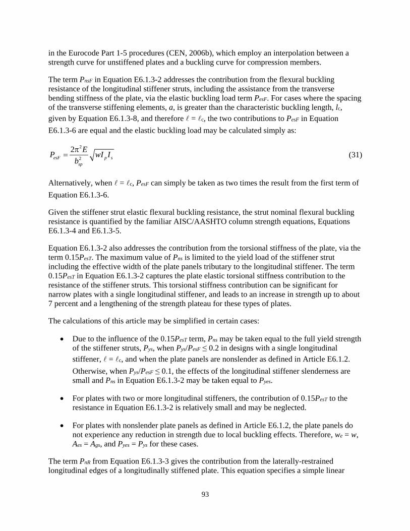
93
in the Eurocode Part 1-5 procedures (CEN, 2006b), which employ an interpolation between a strength curve for unstiffened plates and a buckling curve for compression members.
The term PnsF in Equation E6.1.3-2 addresses the contribution from the flexural buckling resistance of the longitudinal stiffener struts, including the assistance from the transverse bending stiffness of the plate, via the elastic buckling load term PesF. For cases where the spacing of the transverse stiffening elements, a, is greater than the characteristic buckling length, lc, given by Equation E6.1.3-8, and therefore = c, the two contributions to PesF in Equation E6.1.3-6 are equal and the elastic buckling load may be calculated simply as:
2
2
2esF p s
sp
EP wI Ibπ
= (31)
Alternatively, when = c, PesF can simply be taken as two times the result from the first term of Equation E6.1.3-6.
Given the stiffener strut elastic flexural buckling resistance, the strut nominal flexural buckling resistance is quantified by the familiar AISC/AASHTO column strength equations, Equations E6.1.3-4 and E6.1.3-5.
Equation E6.1.3-2 also addresses the contribution from the torsional stiffness of the plate, via the term 0.15PesT. The maximum value of Pns is limited to the yield load of the stiffener strut including the effective width of the plate panels tributary to the longitudinal stiffener. The term 0.15PesT in Equation E6.1.3-2 captures the plate elastic torsional stiffness contribution to the resistance of the stiffener struts. This torsional stiffness contribution can be significant for narrow plates with a single longitudinal stiffener, and leads to an increase in strength up to about 7 percent and a lengthening of the strength plateau for these types of plates.
The calculations of this article may be simplified in certain cases:
• Due to the influence of the 0.15PesT term, Pns may be taken equal to the full yield strength of the stiffener struts, Pys, when Pys/PesF ≤ 0.2 in designs with a single longitudinal stiffener, = c, and when the plate panels are nonslender as defined in Article E6.1.2. Otherwise, when Pys/PesF ≤ 0.1, the effects of the longitudinal stiffener slenderness are small and Pns in Equation E6.1.3-2 may be taken equal to Pyes.
• For plates with two or more longitudinal stiffeners, the contribution of 0.15PesT to the resistance in Equation E6.1.3-2 is relatively small and may be neglected.
• For plates with nonslender plate panels as defined in Article E6.1.2, the plate panels do not experience any reduction in strength due to local buckling effects. Therefore, we = w, Aes = Ags, and Pyes = Pys for these cases.
The term PnR from Equation E6.1.3-3 gives the contribution from the laterally-restrained longitudinal edges of a longitudinally stiffened plate. This equation specifies a simple linear
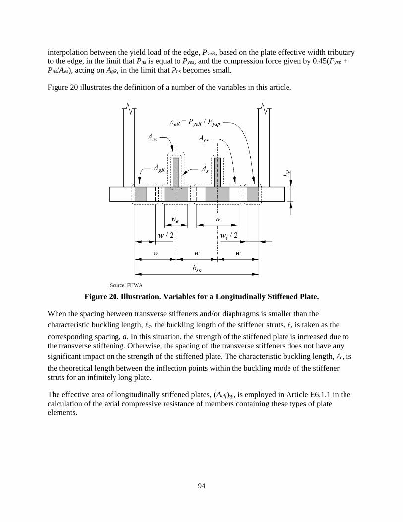
94
interpolation between the yield load of the edge, PyeR, based on the plate effective width tributary to the edge, in the limit that Pns is equal to Pyes, and the compression force given by 0.45(Fysp + Pns/Aes), acting on AgR, in the limit that Pns becomes small.
Figure 20 illustrates the definition of a number of the variables in this article.
Source: FHWA
Figure 20. Illustration. Variables for a Longitudinally Stiffened Plate.
When the spacing between transverse stiffeners and/or diaphragms is smaller than the characteristic buckling length, c, the buckling length of the stiffener struts, , is taken as the corresponding spacing, a. In this situation, the strength of the stiffened plate is increased due to the transverse stiffening. Otherwise, the spacing of the transverse stiffeners does not have any significant impact on the strength of the stiffened plate. The characteristic buckling length, c, is the theoretical length between the inflection points within the buckling mode of the stiffener struts for an infinitely long plate.
The effective area of longitudinally stiffened plates, (Aeff)sp, is employed in Article E6.1.1 in the calculation of the axial compressive resistance of members containing these types of plate elements.

95
3.1.2.9. Nominal Compressive Resistance of Members Containing Longitudinally Stiffened Plates, Resistance and Effective Area of Plates with Unequally-spaced and/or Unequal-size Longitudinal Stiffeners
This section provides rules for an accurate to conservative application of the Article E6.1.3 provisions, developed for longitudinally stiffened plates having equally-spaced equal-size longitudinal stiffeners, to cases in which the stiffeners are not equally spaced and/or are not of equal size.
The following Case (1) addresses situations such as the calculation of the axial compressive resistance of a longitudinally stiffened web having a single longitudinal stiffener placed closer to the edge subjected to flexural compression. This idealization considers the contribution of the plate torsion in Equation E6.1.3-11 and the plate lateral bending in the second term of Equation E6.1.3-6 to the resistance of the longitudinal stiffener strut conservatively, by using the contribution from these terms obtained if the longitudinal stiffener were placed at the middle of the overall plate width.
Specifically for Case (1):
• w is taken as bsp/2 in calculating PesT from Equation E6.1.3-11, in calculating the plate contribution in the second term of Equation E6.1.3-6, and in calculating the characteristic length from Equation E6.1.3-8.
• All the additional contributions to the resistance of the single stiffener strut are determined by the provisions of Article E6.1.3 using the average of the actual gross and effective plate widths of the panels on each side of the longitudinal stiffener for w and we, respectively.
• The values of the contribution from each of the laterally-restrained longitudinal edges of the longitudinally stiffened plate, PnR1 and PnR2, are determined from Equation E6.1.3-3 using the values of Pns, Pyes, and Ags for the longitudinal stiffener, and using the separate actual total and effective plate widths of the panel adjacent to each edge for w and we, respectively, in the calculation of AgR and PyeR.
The following Case (2) addresses general unequal spacing and/or unequal size of the longitudinal stiffeners by idealizing the contribution from the plate lateral bending and plate torsion in the above equations conservatively based on the contributions from an equivalent plate with a uniform stiffener spacing, wmax, equal to the maximum spacing between the longitudinal stiffeners, or the longitudinal stiffeners and the laterally-restrained longitudinal edge, using a total equivalent plate width equal to (n + 1)wmax, where n is the total number of longitudinal stiffeners. The base longitudinal stiffener strut resistances, PnsF, are taken as the minimum PnsF value from all the longitudinal stiffener struts, neglecting any capability for redistribution of load from weak longitudinal stiffener struts to stronger struts. In addition, the plate torsional stiffness contribution to the elastic buckling resistance of the individual stiffener struts, PesT, is assumed to be neglible.

96
Specifically for Case (2):
• In calculating the contribution from the second term in Equation E6.1.3-6, and in calculating the characteristic length from Equation. E6.1.3-8, w is taken as the maxmum panel width within the longitudinally stiffened plate, wmax, and bsp is taken as (n + 1)wmax
• The contribution PesT from Equation E6.1.3-11 is taken as zero.
• The compressive resistance of the individual stiffener struts, PnsF, is calculated using the sum of the tributary plate widths from the panels on each side of the coreesponding longituidinal stiffeners, (w1 + w2)/2 and (we1 + we2)/2, and PnsF is then taken as the minimum value from all of the stiffener struts.
• The values of the contribution from each of the laterally-restrained longitudinal edges of the longitudinally stiffened plate, PnR1 and PnR2, are determined from Equation E6.1.3-3 using the minimum Pns and the Pyes value for the corresponding longitudinal stiffener, and using the separate actual total and effective plate widths of the panel adjacent to each edge for w and we, respectively, in the calculation of AgR and PyeR.
The Engineer is reminded that just because Specification provisions allow one to calculate the resistance for arbitrary structural arrangements does not necessarily indicate that the use of such arrangements is good structural design practice.
Case 1: Longitudinally stiffened plates containing one longitudinal stiffener, placed other than at the middle of the plate width
The nominal compressive resistance of plates with a single longitudinal stiffener placed other than at the middle of the plate width shall be determined as follows:
1 2nsp ns nR nRP P P P= + + (32)
in which:
Pns = nominal compressive resistance of the individual stiffener strut composed of the stiffener plus the tributary width of the longitudinally stiffened plate under consideration (kip)
0.15nsF esT yesP P P= + ≤ (33)
and
PnR1, PnR2 = nominal compressive resistance provided by the individual laterally-restrained longitudinal edges of the longitudinally stiffened plate under consideration (kip)
1 0.45
, 1 and 2
ns nsnsysp gRi yeRi
yes yeses
yeRi
P PPF A PP PA
P i
− += +
≤ =
(34)
97
where:
The following terms apply to the calculation of Pns:
nsFP = nominal flexural buckling resistance of the individual stiffener strut (kip) determined as follows:
• If 2.25ys
esF
PP
≤ , then:
0.658ys
esF
PP
nsF yesP P= (35)
• Otherwise:
0.877 esFnsF es
gs
PP AA
= (36)
esFP = elastic flexural buckling resistance of the individual stiffener strut (kip)
22
22 32
ps
sp
EIEIb
ππ= +
(37)
Ip = lateral moment of inertia of a unit width of the longitudinally stiffened plate under consideration (inch3)
( )
3
212 1spt
=−ν
(38)
= buckling length of the individual stiffener strut, taken equal to the smaller of a and c (inch), where:
• a = longitudinal spacing between locations of transverse stiffeners or diaphragms that provide transverse lateral restraint to the longitudinally stiffened plate under consideration (inch)
• c = characteristic buckling length of the stiffener struts of the longitudinally stiffened plate under consideration (inch)
1/42 ssp
sp p
Ibb I
=
(39)
Aes = effective area of the individual stiffener strut (inch2)
1 2
2e e
s spw wA t+ = +
(40)
Ags = gross area of the individual stiffener strut (inch2)

98
1 2
2s spw wA t+ = +
(41)
PesT = plate torsional stiffness contribution to the elastic buckling resistance of the individual stiffener strut (kip)
( )
32
2 31sp
sp
Gtb
π=
−ν (42)
Pyes = effective yield load of an individual stiffener strut (kip)
ysp esF A= (43)
Pys = yield load of an individual stiffener strut (kip)
ysp gsF A= (44)
where:
ν = Poisson’s ratio = 0.3 As = gross area of an individual longitudinal stiffener, excluding the tributary width of the
longitudinally stiffened plate under consideration (inch2) bsp = total width of the longitudinally stiffened plate, taken as the inside distance between
the plates providing lateral restraint to its longitudinal edges (inch) Fysp = specified minimum yield strength of the longitudinally stiffened plate under
consideration (ksi) G = shear modulus of elasticity for steel = 0.385E (ksi) Is = moment of inertia of an individual stiffener strut composed of the stiffener plus the
gross tributary width, (w1 + w2)/2, of the longitudinally stiffened plate under consideration, taken about an axis parallel to the face of the longitudinally stiffened plate and passing through the centroid of the combined area of the longitudinal stiffener and its gross tributary plate width (inch4)
tsp = thickness of the longitudinally stiffened plate under consideration (inch) w1, w2 = widths of the plate on each side of the longitudinal stiffener between its centerline
and the inside of the laterally-restrained longitudinal edge of the longitudinally stiffened plate under consideration, equal to the gross tributary width on each side of the longitudinal stiffener (inch)
we1, we2 = effective widths of the plate tributary to the longitudinal stiffener, on each side of the longitudinal stiffener, taken as be1 /2 and be2/2, where be1 and be2 calculated as specified in Article 6.9.4.2.2b with w1 and w2 substituted for b, with Fcr taken as Fysp and with λr taken as specified in Article E6.1.2 for the plate panels on each side of the longitudinal stiffener (inch)
The following additional terms apply to the calculation of PnR1 and PnR2:
AgR1, AgR2 = gross tributary area of the laterally-restrained longitudinal edges of the longitudinally stiffened plate under consideration (inch2)
99
, 1 and 22
isp
w t i= = (45)
PyeR1, PyeR2 = effective yield load of an individual laterally-restrained longitudinal edges of the longitudinally stiffened plate under consideration (kip)
, 1 and 2ysp eRiF A i= = (46)
AeR1, AeR2 = effective tributary area of the laterally-restrained longitudinal edges of the longitudinally stiffened plate under consideration (inch2)
, = 1 and 22
eisp
w t i= (47)
The longitudinal stiffeners shall satisfy the requirements of Article E6.1.4. Transverse stiffeners, when utilized to strengthen or stiffen a longitudinally stiffened plate, shall satisfy the requirements of Article E6.1.5.
The effective area of the longitudinally stiffened plate shall be calculated as follows:
( ) nspeff sp
ysp
PA
F= (48)
Case 2: Longitudinally stiffened plates containing more than one longitudinal stiffener of unequal size and/or unequal spacing between stiffeners and/or between the stiffeners and the longitudinal edge of the plate
The nominal compressive resistance of plates more than one longitudinal stiffener of unequal size and/or unequal spacing between stiffeners and/or between the stiffeners and the longitudinal edge of the plate shall be determined as follows:
1 2nsp nsF nR nRP nP P P= + + (49)
in which:
PnsF = minimum value of the nominal compressive resistance of the individual stiffener struts composed of the stiffeners plus the corresponding tributary widths of the longitudinally stiffened plate under consideration (kip), determined as follows
• If 2.25ys
esF
PP
≤ , then:
0.658ys
esF
PP
nsF yesP P= (50)
• Otherwise:
100
0.877 esFnsF es
gs
PP AA
= (51)
and
PnR1, PnR2 = nominal compressive resistance provided by the individual laterally-restrained longitudinal edges of the longitudinally stiffened plate under consideration, using the Pyes of the strut having the minimum Pns value (kip)
1 0.45
, 1 and 2
nsF nsFnsFysp gRi yeRi
yes yeses
yeRi
P PPF A PP PA
P i
− += +
≤ =
(52)
where:
n = number of longitudinal stiffeners
The following terms apply to the calculation of PnsF:
esFP = elastic flexural buckling resistance of an individual stiffener strut (kip)
( )
222
42 3max1
ps EIEIn w
ππ= +
+
(53)
Ip = lateral moment of inertia of a unit width of the longitudinally stiffened plate under consideration (inch3)
( )
3
212 1spt
=−ν
(54)
= buckling length of the individual stiffener struts, taken equal to the smaller of a and
c (inch), where:
• a = longitudinal spacing between locations of transverse stiffeners or diaphragms that provide transverse lateral restraint to the longitudinally stiffened plate under consideration (inch)
• c = characteristic buckling length of the stiffener struts of the longitudinally stiffened plate under consideration (inch)
( )1/4
1smax
max p
In ww I
= +
(55)
Aes = effective area of the individual stiffener struts (inch2)
1 2
2e e
s spw wA t+ = +
(56)
Ags = gross area of the individual stiffener struts (inch2)

101
1 2
2s spw wA t+ = +
(57)
Pyes = effective yield load of the individual stiffener struts (kip)
ysp esF A= (58)
Pys = yield load of the individual stiffener struts (kip)
ysp gsF A= (59)
where:
ν = Poisson’s ratio = 0.3 As = gross area of the individual longitudinal stiffeners, excluding the tributary width of
the longitudinally stiffened plate under consideration (inch2) Fysp = specified minimum yield strength of the longitudinally stiffened plate under
consideration (ksi) G = shear modulus of elasticity for steel = 0.385E (ksi) Is = minimum value of the moments of inertia of the individual stiffener struts composed
of the stiffeners plus the gross tributary width, (w1 + w2)/2,, of the longitudinally stiffened plate under consideration, taken about an axis parallel to the face of the longitudinally stiffened plate and passing through the centroid of the combined area of the longitudinal stiffeners and their gross tributary plate width (inch4)
tsp = thickness of the longitudinally stiffened plate under consideration (inch) w1, w2 = widths of the plate between the centerline of the individual longitudinal stiffener
under consideration and the centerline of the adjacent longitudinal stiffenere, or between the centerline of the longitudinal stiffener and the inside of the laterally-restrained longitudinal edge of the longitudinally stiffened plate under consideration, as applicable, equal to the gross tributary widths on each side of the longitudinal stiffeners (inch)
we1, we2 = effective widths of the plate tributary to the longitudinal stiffeners, on each side of the longitudinal stiffeners, taken as be1 /2 and be2/2, where be1 and be2 calculated as specified in Article 6.9.4.2.2b with w1 and w2 substituted for b, with Fcr taken as Fysp and with λr taken as specified in Article E6.1.2 for the plate panels on each side of the longitudinal stiffeners (inch)
wmax = maximum panel width within the stiffened plate (inch)
The following additional terms apply to the calculation of PnR1 and PnR2:
AgR1, AgR2 = gross tributary area of the laterally-restrained longitudinal edges of the longitudinally stiffened plate under consideration, with w1 and w2 corresponding to the longitudinal stiffener adjacent to the edge (inch2)
, 1 and 22
isp
w t i= = (60)
PyeR1, PyeR2 = effective yield load of an individual laterally-restrained longitudinal edges of the longitudinally stiffened plate under consideration (kip)

102
, 1 and 2ysp eRiF A i= = (61)
AeR1, AeR2 = effective tributary area of the laterally-restrained longitudinal edges of the longitudinally stiffened plate under consideration, with we1 and we2 corresponding to the longitudinal stiffener adjacent to the edge (inch2)
, = 1 and 22
eisp
w t i= (62)
The longitudinal stiffeners shall satisfy the requirements of Article E6.1.4. Transverse stiffeners, when utilized to strengthen or stiffen a longitudinally stiffened plate, shall satisfy the requirements of Article E6.1.5.
The effective area of plates with equally-spaced equal-size longitudinal stiffeners shall be calculated as follows:
( ) nspeff sp
ysp
PA
F= (63)
3.1.2.10. Nominal Compressive Resistance of Members Containing Longitudinally Stiffened Plates, Longitudinal Stiffener Requirements (Article E6.1.4)
The provisions contained in Article E6.1.4 apply generally for the design of the longitudinal stiffeners on all longitudinally stiffened plates.
Yield Strength Requirements
Early yielding of lower strength stiffeners would result in a significant reduction in their effectiveness; therefore, the specified minimum yield strength of the stiffeners should not be less than the specified minimum yield strength of the plate to which they are attached. Otherwise, the strength of the stiffened plate may be calculated by taking Fysp equal to the specified minimum yield strength of the stiffeners in Articles E6.1.1 and E6.1.3. Tee-sections may not be available in higher grades of steel. In these cases, a tee section can be fabricated from plates or bars cut from plate.
Detailing Requirements
Longitudinal stiffeners must be structurally continuous along their length to develop the resistance of the corresponding stiffened plates. Longitudinal stiffeners should either be continuous through any intermediate internal diaphragms or transverse stiffeners, or discontinued and positively attached to each side of the diaphragms or transverse stiffeners such that they act as continuous elements. Cutouts may be used in diaphragms or transverse stiffeners to accommodate continuous longitudinal stiffeners. Where cutouts are used, the longitudinal stiffeners should be attached to the internal diaphragms or transverse stiffeners. Tee-section longitudinal stiffeners may be conveniently attached to the diaphragms or transverse stiffeners by welds or bolts with a pair of clip angles. A welded tab plate may also be used to make the

103
attachment. Similar attachment of the longitudinal stiffeners should also be considered at end diaphragms.
Should it be necessary to discontinue a longitudinal stiffener at a bolted field splice, consideration should be given to extending the stiffener to the free edge of the plate element, where the normal stress is zero. If the plate element on the other side of the splice is longitudinally unstiffened, its resistance should be checked accordingly to determine if the flange is satisfactory without a stiffener or if a slight increase in the flange thickness will suffice without providing a stiffener. Where necessary to extend the longitudinal stiffener beyond a field splice, splicing the stiffener across the field splice is recommended. The continuity of the longitudinal stiffener and the integrity of the stiffened plate must be maintained across the splice.
If the stiffener is terminated outside the splice and the termination is subject to a net tensile stress, determined as specified in Article 6.6.1.2.1, the termination of the stiffener weld to the plate must be checked for fatigue according to the terminus detail. Terminating the longitudinal stiffener by positively attaching it to a transverse stiffener is also another possible alternative, which may lead to a larger fatigue resistance.
Selection of Longitudinal Stiffener Proportions to Prevent Stiffener Local Buckling and Tripping
Equation E6.1.4-1 ensures that the resistance of longitudinal stiffeners will not be impacted by local buckling of the stiffener cross-section elements. Equation E6.1.4-2 ensures against torsional buckling, or tripping, of tee and angle section stiffeners about the edge of the stiffener attached to the plate. For flat plate longitudinal stiffeners, these two equations give the same requirement; therefore, only Equation E6.1.4-1 needs to be checked. Equation E6.1.4-2 neglects the warping contribution to the torsional resistance, which tends to be small in many practical cases considering the length between the locations of torsional restraint at transverse stiffeners and/or diaphragms.
Derivation of Longitudinal Stiffener Tripping Limit
Generally, the torsional buckling of longitudinal stiffeners about the line of their connection to the stiffened plate should be avoided. A simple way of accomplishing this is to ensure that the stiffeners can essentially develop their full yield resistance without any impact from torsional buckling. For components subjected to concentric axial compression, this is ensured by requiring that the component elastic critical stress be larger than two times the component yield strength. Assuming open cross-section stiffeners with relatively large transverse stiffener or diaphragm spacing, such that the contribution of any warping torsion stiffness is small compared to the St. Venant torsional stiffness, the above condition may be expressed as
( )2
2 1cr yps ps
GJ E JF FI I
= = ≥+ ν
(64)
Upon rearranging this equation, one obtains Equation 6.9.4.2.2e-2, but with a coefficient of 5.2. This coefficient is then rounded to 5.0.
For the common case of a flat plate stiffener,

104
3 3 3
3 12 3psb t t b b tI = + ≅ (65)
and
3
3btJ ≅ (66)
As such, Equation 64 reduces to
2
5.0 yspFtEb
≥
(67)
which gives the nonslender plate limit
0.45rysp
EF
λ ≤ (68)
listed in Table 17 (Specification Table 6.9.4.2.1-1). This explains the equivalency of Equations 6.9.4.2.2e-2 and 6.9.4.2.2e-1 for flat plate longitudinal stiffeners
Recommended Design Equations versus Refined Calculations for Evaluation of Existing Structures
Satisfaction of Equation E6.1.4-1 is considered most appropriate for new designs. In cases where Equation E6.1.4-1 is violated in any cross-section component of longitudinal stiffeners in existing structures, it is recommended that the resistance of the longitudinally stiffened plate specified in Article E6.1.3 should be calculated by using an effective width equal to λrt within the corresponding longitudinal stiffener cross-section components. For plates of the longitudinal stiffener cross-section supported only on one longitudinal edge, such as flat plate stiffeners and flanges of tee-section stiffeners, the effective width λrt is placed adjacent to that edge. For plates of the longitudinal stiffener cross-section supported on two longitudinal edges, such as the stem of tee-section stiffeners, half of the above effective width is placed adjacent to each edge. This approach gives an appropriate estimate of the influence of slender cross-section elements in longitudinal stiffeners. The use of the traditional approach of substituting a factored longitudinal stress in the stiffener, fa, due to axial compression and flexure is not recommended. The true stresses in the longitudinal stiffener can easily approach Fy in certain portions of the stiffener length, due to the axial compression plus second-order bending in the stiffener, including the influence of stiffener initial out-of-straightness. The wavelength associated with local buckling of the stiffener cross-section components is typically relatively short, and this can lead to a local failure along the stiffener length that is not captured by simply substituting fa for Fy within Equation E6.1.4-1.
Equation E6.1.4-2 tends to require relatively thick plates for tee and angle stiffeners to ensure that the stiffener does not fail in a mode involving torsional buckling about the connection to the
105
stiffened plate, commonly referred to as tripping. This equation is considered as being most appropriate for new designs. Equation E6.1.4-2 neglects the potential restraint from the stiffened plate to twisting of the stiffener about its connection to the plate. Quantification of this torsional restraint is a complex problem that has not yet been fully studied.
As discussed above, traditional approaches to conservatively estimate plate local buckling resistances have sometimes replaced Fy in equations for the nonslender plate limit, such as in Equation E6.1.4-1, by the factored longitudinal compressive stress in the component due to axial force plus bending within the structural member, fa. The tripping limit state for an open section longitudinal stiffener is a different problem than local buckling of a flat plate. As a coarse relaxed estimate of the requirement in E6.1.4-2, to avoid tripping, and until further research can be conducted to better ascertain an improved estimate of the tripping resistance, it is recommended that Fy in this equation may be replaced by the average between the stiffener specified minimum yield strength, Fy, and the maximum factored longitudinal stress in the stiffener, fa. The use of the factored longitudinal stress in this way as a modified stiffener tripping check is considered sufficient because of the long buckling length associated with the tripping limit state.
Wolchuk and Mayrbaurl (1980) Section 1.7.207 provides specific equations that aim to quantify the restraint from the stiffened plate to twisting of open-section stiffeners about their connection to the plate. For tee and angle section stiffeners, these equations give a more optimistic assessment of the stiffener torsional stability for:
• Smaller w/t,
• Smaller b/t of the tee stem,
• Larger ry/d of the stiffener, where ry is the radius of gyration of the tee stiffener alone about the axis perpendicular to the plate, not considering the tributary width of the stiffened plate, and d is the total depth of the stiffener perpendicular to the plate, and
• Applied compressive stress in the stiffened plate, at factored load conditions, less than 0.5Fy, versus applied compressive stress greater than 0.5Fy.
It should be noted that an unpublished 1975 draft proposal for British design standards as well as research by Rogers and Dwight (1976) is referenced as the background for these equations. Eurocode 3 Part 1-5 (CEN, 2006b) does not explicitly recognize these developments. This standand requires satisfaction of Equation E6.1.4-2 but with a coefficient of 5.3 rather than 5.0 “unless a more advanced method of analysis is carried out.” Johansson et al. (2007) derive equations quantifying the theoretical elastic buckling of open-section stiffeners with an idealized elastic continuous torsional restraint from the stiffened plate. They then explain that the elastic torsional restraint from the plate is affected by the longitudinal compressive stresses in the plate, and suggest that this restraint should be reduced by a simple factor of 3.0 to accunt for these effects. In the view of the authors of this report, all of these developments should be compared thoroughly to experimental test data and test simulation data before recommendations can be provided for refined calculations that ensure the torsional stability of tee and angle section stiffeners.
106
Longitudinal Stiffener Minimum Slenderness Limit to Ensure Against Excessive Out-of-Plane Deflection of a Stiffened Plate
The limit a/rs ≤ 120 on longitudinally stiffened flange plates ensures against excessive out-of-plane deflection of a stiffened plate under its self-weight plus a small transverse concentrated load (White et al. 2019). This limit is applied regardless of whether or not the member is in a horizontal configuration in the final constructed geometry, to limit such deflections with the member oriented horizontally during construction operations. This limit need not be satisfied for flanges with bsp/tsp ≤ 90 since the out-of-plane deformations due to the above load effects tend to be small in these cases without consideration of the longitudinal stiffening.
3.1.2.11. Nominal Compressive Resistance of Members Containing Longitudinally Stiffened Plates, Basic Transverse Stiffener Requirements (Article E6.1.5)
The provisions contained in Article E6.1.5 apply for the design of transverse stiffeners that are provided to enhance the resistance of a longitudinally stiffened plate subjected to a net axial compression within the plate, with or without flexure within the plane of the plate.
General Transverse Stiffener Strength and Stiffness Requirements
In longitudinally stiffened plates containing transverse stiffeners in which:
• The characteristic length, c, from Equation E6.1.3-8 is less than the spacing, a, defined in Article E6.1.3, and
• The transverse stiffeners are not subjected to any directly applied bending or axial compression,
the transverse stiffeners do not serve any purpose to enhance the axial compressive resistance of the longitudinally stiffened plate, and, any potential destabilization of the transverse stiffeners from the longitudinal compression in the plate is not a consideration. Therefore, in these cases, the moment of inertia requirements of Article E6.1.5.2 may be waived.
The provisions in Article E6.1.5.2 do not apply for cases where the transverse stiffener is subjected to a concentrically applied axial compressive force, and/or directly applied loads causing bending of the stiffener, whether or not the characteristic length, lc, is less than the spacing, a. Section 3.1.2.12 discusses example cases where this may potentially occur, including top or bottom struts of internal cross-frames that serve as transverse stiffeners to enhance the resistance of the longitudinally stiffened plate, and provides an alternative moment of inertia requirement to handle such cases.
The minimum requirement that the transverse stiffener moment of inertia, It, defined in Article E6.1.5.2 be greater than or equal to the moment of inertia, Is, of the longitudinal stiffeners defined in Article E6.1.3, combined with the requirement from Equation E6.1.4-3, helps ensure against excessive out-of-plane deflection of a stiffened plate under its self-weight plus a small transverse concentrated load in cases where the calculated axial compression in the plate is small, and therefore the requirements from Equations E6.1.5.2-1 and E6.1.5.2-2 are small (White
107
et al., 2019). One example of this situation is a case where transverse stiffeners are installed to serve only as points of termination of longitudinal stiffeners in a tension zone. In designs where bsp/amax is close to or greater than 1.0, where bsp is the total width of the stiffened plate as defined in Article E6.1.4 and amax is the largest of the longitudinal spacings to the adjacent transverse stiffeners or diaphragms providing lateral restraint to the plate, It may need to be larger than Is to satisfy out-of-plane deflection criteria under service loads (White et al., 2019).
Transverse stiffeners should also satisfy Equations E6.1.4-1 and E6.1.4-2 to avoid potential local buckling of the elements of the stiffener, as well as torsional buckling, or tripping, of tee-section stiffeners about the edge of the stiffener attached to the plate. These requirements are easily satisfied by flat plate transverse stiffeners, and as noted in Section 3.1.2.10, Equations E6.1.4-1 and E6.1.4-2 are equivalent for these stiffener types. However, Equation E6.1.4-2 can be prohibitive for larger transverse stiffeners containing flange elements, such as tee sections, in large box-section members. In these cases, the transverse stiffeners should be designed less conservatively by considering them explicitly as beam-column or beam members subjected to the axial force and/or bending moment induced in the stiffener, as discussed further in Section 3.1.2.12
Transverse Stiffener Detailing Requirements
Longitudinal stiffeners must be structurally continuous at any transverse stiffeners. Cutouts may be placed in the transverse stiffeners to accommodate the continuous longitudinal stiffeners; otherwise, a top or bottom strut of an internal cross-frame, or a wide-flange section, satisfying the requirements specified in Article E6.1.5 may serve as a transverse stiffener and be placed across the outstanding end of the longitudinal stiffeners. In either case, the longitudinal stiffeners should be attached to the transverse stiffeners. Tee-section longitudinal stiffeners may be conveniently attached to the transverse stiffeners by welds or bolts with a pair of clip angles. A welded tab plate may also be used to attach the stiffeners.
Alternatively, transverse stiffeners that are welded to the stiffened plate may be discontinued and welded to the continuous longitudinal stiffeners such that they act as continuous elements across the longitudinal stiffeners as shown in Table 6.6.1.2.4-1.
Transverse Stiffener Connection Requirements
In all cases, the attachment of a longitudinal stiffener to the transverse stiffener should be designed for the following force perpendicular to the plane of the stiffened plate:
10.01u ups uV P V= +
(69)
where:
Pups = factored axial force within the longitudinal stiffener strut under consideration, composed of the longitudinal stiffener and the tributary plate width, determined from a structural analysis considering the gross cross-section (kip)

108
Vul1 = first-order force transferred by the attachment due to any directly applied factored loads on the longitudinal stiffener perpendicular to the plane of the stiffened plate, as applicable (kip)
The attachment at the ends of a transverse stiffener should be designed to transmit the following force perpendicular to the plane of the stiffened plate:
10.005 0.01sput up ut ut
bV P P Va
= + +
(70)
where a, bsp, and Pup are defined in Article E6.1.5.2, Put is the direct factored axial compression force in the transverse stiffener, as applicable, and:
Vut1 = first-order force in the direction perpendicular to the plane of the stiffened plate at the attachment due to any directly applied factored loads, as applicable (kip)
Stability Bracing Requirements – Transverse Stiffener Minimum Moment of Inertia for Basic Situations to Ensure Sufficient Stiffener Stiffness and Strength
Equation E6.1.5.2-1 is a generalized and simplified form of the moment of inertia requirement given by Equation C6.11.11.2-4 for transverse stiffeners in composite box-section compression flanges. This equation ensures adequate lateral stiffness to resist the destabilizing load effects from the factored longitudinal compression force in the stiffened plate, including the effects from the longitudinal stiffeners. In many situations, the factored longitudinal compression force in the stiffened plate, quantified by the term Pup, provides the only significant demand on the transverse stiffeners.
Equation E6.1.5.2-2 is an indirect moment of inertia requirement necessary to ensure that the transverse stiffeners have adequate lateral strength to resist the destabilizing load effects from the factored longitudinal compression force in the plate, including the effects from the longitudinal stiffeners. Alternatively, Equation E6.1.5.2-2 may be expressed as the following general requirement on c, given a provided moment of inertia, It, to avoid early yielding of the stiffener:
3 4
min
21200 y tsp
up sp
F Ic bP bEa E
≤ − π
(71)
The moment of inertia of the transverse stiffener is commonly calculated assuming a width of the stiffened plate equal to 9tsp on each side of the stiffener as a flange contribution from the plate, as stated in the definition for It. However, a width of bsp/10, or a total width of bsp/5, may be more appropriate and may be used. This width is based on the consideration of shear lag for the plate acting as a flange of the transverse stiffener. The width 9tsp is recommended within these provisions as a conservative value for one-half of this flange width, recognizing that there may be some reduction in the effectiveness of the plate acting as a flange of the transverse stiffener due to high normal or shear stresses from other actions in the plate. Either of the above values for

109
the width of the plate contributing to the moment of inertia of the transverse stiffener is limited by the actual dimension available on each side of the stiffener, avoiding any overlap with contributing parts to adjacent stiffeners or diaphragms.
3.1.2.12. Nominal Compressive Resistance of Members Containing Longitudinally Stiffened Plates, Advanced Transverse Stiffener Requirements
Top and bottom struts of internal intermediate cross-frames are commonly designed to resist a direct axial compression, as struts (Fan and Helwig, 2002), as well as to serve as transverse stiffeners to enhance the compressive resistance of a longitudinally stiffened plate element.
In addition, transverse stiffners in large box sections, such as a steel bridge tower, are commonly subjected to general direct axial load and bending in addition to serving in their function to reduce the buckling length of the longitudinal stiffeners. Figure 21 shows a conceptual sketch of a representative bridge tower leg. The side of the tower leg is wide enough such that the vertical longitudinal stiffeners would have to be very large to have adequate stiffness. Therefore, transverse stiffeners and internal bracing cross-frames are necessary to provide support to the longitudinal stiffeners at certain intervals along the height of the tower.
Source: FHWA
Figure 21. Illustration. Concceptual sketches of a stiffened bridge tower, and transverse stiffeners in the wall of the bridge tower.
In this type of application, the tower wall is a longitudinally stiffened plate. This plate resists significant (vertical) axial compression, represented by the term Pup in the equations provided in the recommended Article E6.1.5 and discussed in Section 3.1.2.11. The transverse stiffeners serve a stability bracing role in restraining the out-of-plane movement of the tower wall under the action of the loads Pup. However, due to wind loading, maintenance trolley loads, and varying taper of the tower at a given cross-section, the transverse stiffeners are also subjected to direct axial forces. These are denoted by the symbol Put in the following developments.
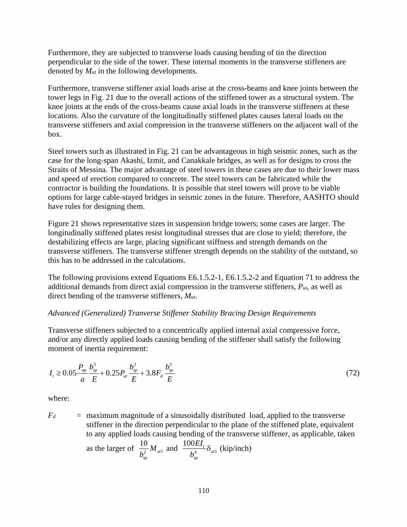
110
Furthermore, they are subjected to transverse loads causing bending of tin the direction perpendicular to the side of the tower. These internal moments in the transverse stiffeners are denoted by Mut in the following developments.
Furthermore, transverse stiffener axial loads arise at the cross-beams and knee joints between the tower legs in Fig. 21 due to the overall actions of the stiffened tower as a structural system. The knee joints at the ends of the cross-beams cause axial loads in the transverse stiffeners at these locations. Also the curvature of the longitudinally stiffened plates causes lateral loads on the transverse stiffeners and axial compression in the transverse stiffeners on the adjacent wall of the box.
Steel towers such as illustrated in Fig. 21 can be advantageous in high seismic zones, such as the case for the long-span Akashi, Izmit, and Canakkale bridges, as well as for designs to cross the Straits of Messina. The major advantage of steel towers in these cases are due to their lower mass and speed of erection compared to concrete. The steel towers can be fabricated while the contractor is building the foundations. It is possible that steel towers will prove to be viable options for large cable-stayed bridges in seismic zones in the future. Therefore, AASHTO should have rules for designing them.
Figure 21 shows representative sizes in suspension bridge towers; some cases are larger. The longitudinally stiffened plates resist longitudinal stresses that are close to yield; therefore, the destabilizing effects are large, placing significant stiffness and strength demands on the transverse stiffeners. The transverse stiffener strength depends on the stability of the outstand, so this has to be addressed in the calculations.
The following provisions extend Equations E6.1.5.2-1, E6.1.5.2-2 and Equation 71 to address the additional demands from direct axial compression in the transverse stiffeners, Put, as well as direct bending of the transverse stiffeners, Mut.
Advanced (Generalized) Tranverse Stiffener Stability Bracing Design Requirements
Transverse stiffeners subjected to a concentrically applied internal axial compressive force, and/or any directly applied loads causing bending of the stiffener shall satisfy the following moment of inertia requirement:
3 2 3
0.05 0.25 3.8up sp sp spt ut d
P b b bI P F
a E E E≥ + + (72)
where:
Fd = maximum magnitude of a sinusoidally distributed load, applied to the transverse stiffener in the direction perpendicular to the plane of the stiffened plate, equivalent to any applied loads causing bending of the transverse stiffener, as applicable, taken
as the larger of 12
10ut
sp
Mb
and 14
100 tut
sp
EIb
δ (kip/inch)
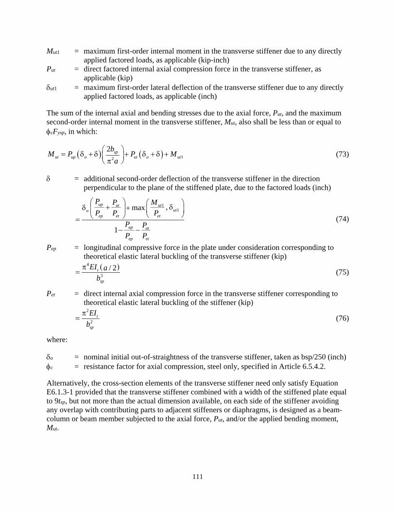
111
Mut1 = maximum first-order internal moment in the transverse stiffener due to any directly applied factored loads, as applicable (kip-inch)
Put = direct factored internal axial compression force in the transverse stiffener, as applicable (kip)
δut1 = maximum first-order lateral deflection of the transverse stiffener due to any directly applied factored loads, as applicable (inch)
The sum of the internal axial and bending stresses due to the axial force, Put, and the maximum second-order internal moment in the transverse stiffener, Mut, also shall be less than or equal to φcFysp, in which:
( ) ( ) 12
2 sput up o ut o ut
bM P P Ma
= δ + δ + δ + δ + π (73)
δ = additional second-order deflection of the transverse stiffener in the direction perpendicular to the plane of the stiffened plate, due to the factored loads (inch)
11,max
1
up ut ututo
ep et et
up ut
ep et
P P MP P P
P PP P
+ δδ + =
− − (74)
Pep = longitudinal compressive force in the plate under consideration corresponding to theoretical elastic lateral buckling of the transverse stiffener (kip)
( )4
3/ 2t
sp
EI ab
π= (75)
Pet = direct internal axial compression force in the transverse stiffener corresponding to theoretical elastic lateral buckling of the stiffener (kip)
2
2t
sp
EIb
π= (76)
where:
δo = nominal initial out-of-straightness of the transverse stiffener, taken as bsp/250 (inch) φc = resistance factor for axial compression, steel only, specified in Article 6.5.4.2.
Alternatively, the cross-section elements of the transverse stiffener need only satisfy Equation E6.1.3-1 provided that the transverse stiffener combined with a width of the stiffened plate equal to 9tsp, but not more than the actual dimension available, on each side of the stiffener avoiding any overlap with contributing parts to adjacent stiffeners or diaphragms, is designed as a beam-column or beam member subjected to the axial force, Put, and/or the applied bending moment, Mut.

112
Explanation of Advanced (Generalized) Transverse Stiffener Stability Bracing Design Requirements
Equatons 72 and 73 give the stiffness and strength requirements for transverse stiffeners to maintain a node line of negligible deflection in the direction perpendicular to the plane of the stiffened plate. A detailed derivation of this equation and the other related equations below is provided in Section 3.1.2.13. The first term of these equations addresses the demands due to the total factored longitudinal compression force in the stiffened plate, Pup, which is the same as in Article E6.1.5. The second and third terms of these equations account for the demands due to any concentrically applied internal axial compression force in the transverse stiffener, Put, as well as the effects of any directly applied loads causing bending of the transverse stiffener. Each of these terms is discussed further below. The second and third terms in Equations 72 and 73 are zero when there is no internal axial compression force in the stiffener and no directly applied loads causing bending of the stiffener, reducing the moment of inertia requirement to that given by Equation E6.1.5.2-1.
Equation 72 gives a generalized stiffness or moment of inertia requirement for transverse stiffeners. This equation is based on an idealization of the transverse stiffener as a simply-supported element with an initial out-of-straightness of bsp/250, subjected to destabilizing load effects from the total longitudinal compression force in the stiffened plate, Pup, as well as any internal axial compression force in the transverse stiffener, Put. Both of these forces induce bending in the transverse stiffener due to the initial out-of-straightness of the stiffener. The equation also addresses any directly applied loads causing bending of the stiffener, which are represented by the term, Fd, discussed further below. Equation 72 is based on an implicit limit of the additional bending displacement of the transverse stiffener due to the combined effect of all of the above loads to bsp/370. This tends to provide a conservative estimate of the actual bending deflection of the stiffener due to the combined participation of the stiffener and the stiffened plate in resisting the deflections.
Equation 73 provides a generalized estimate of the second-order bending moment demand, Mut, on a transverse stiffener based on the same idealized model employed for the assessment of the moment of inertia requirement given by Equation 72.
The second term in Equation 72 addresses the additional transverse stiffener moment of inertia requirement in cases where the stiffener may be subjected to a direct factored internal axial compression force, Put. The coefficients in the first two terms of Equation 72 are based on limiting the second-order amplification of the transverse stiffener initial out-of-straightness to a factor of 1 + (bsp /370)/(bsp /250) = 1.7. The third term in Equation 72 captures the effects of any directly applied factored loads causing bending of the transverse stiffener.
The loading term in Equation 72, Fd, is the maximum magnitude of an equivalent sinusoidally distributed load applied to the transverse stiffener in the direction perpendicular to the stiffened plate. This load is calculated as the maximum of:
• 12
10 ,utsp
Mb
giving the same maximum first-order stiffener bending moment, Mut1, as that
due to the actual directly applied loads causing bending of the stiffener, and

113
• 14
100 ,tut
sp
EIb
δ giving the same maximum first-order bending deflection, δut1, as the actual
directly applied loads causing bending of the stiffener.
Bending of the nominally out-of-straight transverse stiffener due to the influence of Pup and/or any concentrically applied direct axial force, Put, is not included in Mut1 and δut1. These effects are addressed by the first two terms in Equation 72.
When the term 14
100 tut
sp
EIb
δ governs the value of Fd, the required moment of inertia, It, appears on
both sides of Equation 72. In this case, the solution for the total required It is
3 2
1
0.05 0.25
1 380
up sp sput
tut
sp
P b bP
a E EI
b
+≥
δ−
(77)
For transverse stiffeners subjected to direct loading effects causing bending of the stiffener, the result from this equation may be compared to the result from Equation 72 with Fd taken equal to
12
10ut
sp
Mb
to determine the governing value for It. The term 12
10ut
sp
Mb
typically governs for cases
that are dominated by directly applied loads in the direction perpendicular to the stiffened plate,
whereas the term 14
100 tut
sp
EIb
δ typically governs for cases dominated by bending due to eccentric
axial compression on the transverse stiffener.
In cases where a transverse stiffener is subjected to an internal tension force, it is recommended that Put be taken equal to zero in all of the above requirements, except that the axial tension force should be considered in conjunction with Mut when checking the strength of the stiffener.
The demands from the longitudinal compression force in the plate, Pup, the direct internal axial force in the transverse stiffener, Put, and the directly applied bending effects associated with Mut1 are always taken as being additive in Equations 72 and 73. That is, the out-of-straightness of the transverse stiffener always is assumed to be in a direction that causes bending that is additive with the effects associated with Mut1.
The transfer of the forces and moments to and from the transverse stiffeners must be provided for at all attachments. Equations 69 and 70 quantify the force requirements in the direction perpendicular to the plane of the stiffened plate at these attachments
For transverse stiffeners that satisfy both Equations E6.1.4-1 and E6.1.4-2, as applicable, the strength demands on the transverse stiffeners may be satisfied simply by limiting the maximum combined elastic stress on the stiffener due to the axial compression force, Put, and the second-order bending moment, Mut, to the factored yield stress, φcFysp.
114
Design of Transverse Stiffeners in Large Box-Section Members
In large box-section members, the cross-section of the transverse stiffener will need to be other than a flat plate to adequately satisfy the stiffness and strength demands. In these cases, the satisfaction of Equation E6.1.4-2 by the transverse stiffeners can be prohibitive. As such, the transverse stiffener should be designed as a beam-column or beam member subjected to the axial force, Put, and/or the applied bending moment, Mut. The flexural resistance of a tee-section transverse stiffener may be determined by considering the stiffener as a singly-symmetric I-section member composed of the tee and the width of the stiffened plate tributary to the stiffener. The axial resistance of a tee-section transverse stiffener may be obtained by substituting for Pe in the applicable Equation 6.9.4.1.1-1 or Equation 6.9.4.1.1-2, the smaller of: (1) the elastic flexural buckling resistance of the transverse stiffener, including the tributary width of the stiffened plate to which it is attached, about the centroidal axis of the combined section parallel to the face of the plate; and (2) the following elastic buckling load corresponding to constrained-axis torsional buckling of the tee-section stiffener about the line of attachment to the stiffened plate:
2 2
2
2
yT fTT
spe s
xT yT T cT
EI dGJ
bP A
I I A d
π+
=+ +
(78)
where:
As = total area of the tee-section stiffener, including the tributary width of the stiffened plate to which it is attached (inch2)
AT = gross area of the tee-section stiffener, not considering the tributary width of the stiffened plate to which it is attached (inch2)
IxT = moment of inertia of the tee-section stiffener about its centroidal axis parallel to the face of the stiffened plate, not considering the tributary width of the stiffened plate to which it is attached (inch4)
IyT = moment of inertia of the tee-section stiffener about the centerline of its stem, not considering the tributary width of the stiffened plate to which it is attached (inch4)
JT = St. Venant torsional constant for the tee-section stiffener, not considering the tributary width of the stiffened plate to which it is attached (inch4)
dfT = distance from the mid-thickness of the tee-section stiffener flange to the mid-thickness of the stiffened plate, measured perpendicular to the face of the stiffened plate (inch)
dcT = distance from the centroid of the tee-section stiffener, not considering the tributary width of the stiffened plate to which it is attached, to the mid-thickness of the stiffened plate (inch)
3.1.2.13. Detailed Derivation of Generalized Transverse Stiffener Stability Bracing Requirements
The background to and development of Equations 72 through 76 is presented in this sub-section. Figure 22 shows a pin-ended transverse stiffener providing restraint to a plate that is transmitting a net axial compression of Pup. The plate has a width bsp, and lengths a1 and a2 between the
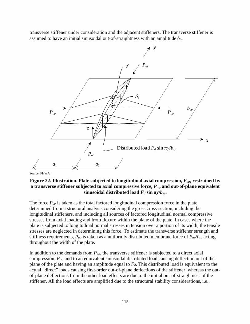
115
transverse stiffener under consideration and the adjacent stiffeners. The transverse stiffener is assumed to have an initial sinusoidal out-of-straightness with an amplitude δo.
Source: FHWA
Figure 22. Illustration. Plate subjected to longitudinal axial compression, Pup, restrained by a transverse stiffener subjected to axial compressive force, Put, and out-of-plane equivalent
sinusoidal distributed load Fd sin πy/bsp.
The force Pup is taken as the total factored longitudinal compression force in the plate, determined from a structural analysis considering the gross cross-section, including the longitudinal stiffeners, and including all sources of factored longitudinal normal compressive stresses from axial loading and from flexure within the plane of the plate. In cases where the plate is subjected to longitudinal normal stresses in tension over a portion of its width, the tensile stresses are neglected in determining this force. To estimate the transverse stiffener strength and stiffness requirements, Pup is taken as a uniformly distributed membrane force of Pup/bsp acting throughout the width of the plate.
In addition to the demands from Pup, the transverse stiffener is subjected to a direct axial compression, Put, and to an equivalent sinusoidal distributed load causing deflection out of the plane of the plate and having an amplitude equal to Fd. This distributed load is equivalent to the actual “direct” loads causing first-order out-of-plane deflections of the stiffener, whereas the out-of-plane deflections from the other load effects are due to the initial out-of-straightness of the stiffener. All the load effects are amplified due to the structural stability considerations, i.e.,
PupPup
Put
Put
Distributed load Fd sin πy/bsp
δo
δ
bsp
x
y
a1 a2
z

116
consideration of equilibrium in the deflected geometry. The potential sources of the axial load Put and the “direct” loads associated with Fd have been explained in the above discussions.
Given the above model and loading, the resulting elastic deflection of the stiffener will be sinusoidal. The second-order analysis solution for this problem is presented as follows:
(1) The governing equilibrium equation is established by equating the destabilizing force effects to the stabilizing reaction.
(2) A procedure is presented for calculation of the Fd values equivalent to different direct loads causing out-of-plane displacement of the transverse stiffener.
(3) An equation is derived for the minimum required moment of inertia, It, in terms of the applied loading effects, given a specified maximum limit on the deflection under the applied loads, δlim.
(4) An expression is derived for the maximum second-order internal moment in the transverse stiffener, i.e., the transverse stiffener flexural strength requirement.
Equilibrium Equation
At the equilibrium position of the deflected structure, where the displacement is δo + δ, with δo being the initial imperfection and δ being the out-of-plane displacement of the transverse stiffener relative to its initial geometry, the destabilizing loads per unit length on the transverse stiffener are:
• From the longitudinal compression on the plate:
1 2 1 2
sin sinup up up upo o
sp sp sp sp sp sp
P P P Py ydz dza ab b b b b bdx dx
δ + δ δ + δπ π + = +
( )1 2
1 1sinup
osp sp
P ya ab b
π += δ + δ
(79)
• From the direct axial compression on the stiffener:
( ) ( )22 2
2 2sin sinout ut ut o
sp sp sp
yd z d yP P Pb bdx dx bπ π πδ + δ= = δ + δ
(80)
• From the destabilizing transverse load:
sindsp
yFbπ (81)

117
The sum of the above loads is the total destabilizing load per unit length of the transverse stiffener. The stabilizing reaction per unit length is obtained from the bending of the transverse stiffener, and may be written as:
2 2 2
2 2 2td M d d zEIdy dy dy
=
(82)
Therefore, assuming constant EIt, one can write
42 4 4
2 2 2sin sint t t
sp sp sp
yd M d z d yEI EI EIb bdy dy dy bπ π πδ= = = δ
(83)
Upon equating the stabilizing reaction to the destabilizing load, one obtains
( ) ( )4 2
1 2
1 1sin sinupt o ut o d
sp spsp spsp
Py yEI P Fb bb a a bb
π π π π δ = + δ + δ + δ + δ +
(84)
or
( ) ( )4 2
1 2
1 1upt o ut o d
sp spsp
PEI P Fb ba ab
π π +δ = δ + δ + δ + δ +
(85)
This is the equilibrium equation employed in the developments below.
Fd Equivalent to the Direct Loads causing Out-of-Plane Displacement of the Transverse Stiffener
The equivalent sinusoidal distributed load corresponding to the “direct” loads, with amplitude Fd, must give internal bending moments that are no smaller than those due to the direct loads. Also it must give out-of-plane deflections that are no smaller than those due to the direct loads.
The maximum first-order bending moment due to the equivalent sinusoidal distributed load acting on the simply-supported transverse stiffener is
2
2sp
d
bF
π (86)
This can be obtained from statics, or by integrating the equation for the destabilizing load per unit length of the stiffener and applying the simply-supported end conditions. Therefore, equivalence of bending moments requires
2
1 2sp
ut d
bM F≥
π (87)
giving

118
2
1 12 2
10d ut ut
sp sp
F M Mb bπ
≥ ≅ (88)
where Mut1 is the maximum first-order internal moment in the transverse stiffener due to any directly applied factored loads.
Furthermore, the maximum out-of-plane deflection due to the equivalent sinusoidal distributed load acting on the simply-supported transverse stiffener is
4
4spd
t
bFEI π
(89)
Therefore, equivalence of deflections requires
4
14spd
utt
bFEI
≥ δπ
(90)
giving
4
1 14 4
100t td ut ut
sp sp
EI EIFb b
π≥ δ ≅ δ (91)
where δut1 is the maximum first-order lateral deflection of the transverse stiffener due to any directly applied factored loads. Equations 88 and 91 are provided in the definition of Fd within the Section 3.1.2.12 provisions.
Required Transverse Stiffener Moment of Inertia
Equation 85 can be solved for the required moment of inertia, given a specified maximum limit on the deflection under load of δ = δlim, giving
( ) ( )24
1 2
1 1 1upspt o lim ut o lim d
splim sp
PbI P FbE a ab
π = + δ + δ + δ + δ + δ π (92)
This equation can be simplified by conservatively taking a1 = a2 = a, where a = min(a1, a2). Upon making this substitution and expanding terms, one obtains
( ) ( )3 2 4
4 2 4
2 1 1up sp sp spo lim o limt ut d
lim lim lim
P b b bI P F
a E E Eδ + δ δ + δ
= + +π δ π δ π δ
(93)
Eurocode 3 Part 1-5 (CEN, 2006b) specifies that an initial out-of-straightness imperfection of the transverse stiffener of
119
( )1 2, ,min300
spo
a a bδ = (94)
should be considered for the design assessment, and that the additional second-order deflection of the transverse stiffener under the action of the load effects should be limited to
300sp
lim
bδ = (95)
If one conservatively takes both of these deflections as bsp /300, then Equation 93 may be written as
3 2 3
0.0411 0.203 3.08up sp sp spt ut d
P b b bI P F
a E E E= + + (96)
The current AASHTO LRFD Article C6.11.11.2 gives the following moment of inertia requirement for transverse flange stiffeners in composite box girders,
3
0.05 up spt
P bI
a E= (97)
considering only the flange axial compression, and taking Pup as the maximum compressive longitudinal flange stress times the total area of the flange, including the flange longitudinal stiffeners. This research recommends the less conservative definition of Pup provided at the beginning of this sub-section. However, for consistency with AASHTO LRFD Equation C6.11.11.2-4, and recognizing the fact that there are various idealizations in the above developments, it is recommended that all the terms in Equation 96 be scaled by 0.05/0.0411, giving the following moment of inertia requirement:
3 2 3
0.05 0.25 3.8up sp sp spt ut d
P b b bI P F
a E E E= + + (98)
o
o
This is Equation 72 of the Section 3.1.2.12 generalized provisions. If one equates all of the terms in Equations 98 and 93, it can be shown that Equation 98 implies δ lim = bsp/366 and δ = bsp/254 given the transverse stiffener analysis model associated with Equation 93 (or rounding to two significant digits, δ lim = bsp/370 and δ = bsp/250).
Transverse Stiffener Flexural Strength Requirement
Given the equivalent destabilizing load per unit length on the simply-supported transverse stiffener,
( ) ( )2
1 2
1 1 sinupo ut o d
sp spsp
P yP Fba a bb
π π + δ + δ + δ + δ +
(99)

120
from Equation 84, the corresponding second-order internal bending moment may be obtained by integrating twice (i.e., converting from the distributed transverse load to the internal shear, and then to the internal moment, and applying the simply-supported end conditions to determine the constants of integration (equal to zero)):
( ) ( )22
21 2
1 1 sinupsput o ut o d
sp spsp
P ybM P Fba a bb
π π = + δ + δ + δ + δ + π (100)
Using the value from Equation 88 for Fd for calculation of the transverse stiffener flexural strength requirement (the other term for Fd relates to the control of the out-of-plane displacements), and conservatively taking a1 = a2 = a, where a = min(a1, a2), the maximum second-order moment within the transverse stiffener may be written as
( ) ( ) 12
2 sput up o ut o ut
bM P P Ma
= δ + δ + δ + δ + π (101)
This is Equation 73 of the Section 3.1.2.12 generalized provisions.
If one substitutes the two requirements for Fd into Equation 85, one obtains
( ) ( )4 2 2 4
1 11 2
1 1max ,up
t o ut o ut t utsp sp sp spsp
PEI P M EIb ba a b bb
π π π π +δ = δ + δ + δ + δ + δ
(102)
Upon solving this equation for δ, one obtains the following expression:
2 2 21
11 2
4 2
1 2
1 1max ,
1 1 1 11
upspo sp sputut ut
t sp t
up sp sput
sp t t
Pb b bMPa aEI b EI
P b bPa ab EI EI
δ + ++ δ π π π δ = +− − π π
(103)
Simplifying, by setting a1 = a2 = a, where a = min(a1, a2), one can write
2 2 21
1
4 2
2 max ,
1 121
upspo sp sputut ut
t sp t
up sp sput
sp t t
Pb b bMPEI b a EI
P b bPb EI EIa
δ ++ δ π π π δ = − − π π
(104)
Finally, upon recognizing that
121
( )
4
3 / 2t
epp
EIPb aπ
= (105)
is the load level corresponding to Pup at theoretical elastic out-of-plane buckling of the transverse stiffener, and
2
2t
etp
EIPb
π= (106)
is the load level corresponding to Put at theoretical elastic out-of-plane buckling of the transverse stiffener, one can simplify the above equation to
11,max
1
up ut ututo
ep et et
up ut
ep et
P P MP P P
P PP P
+ δδ + δ =
− − (107)
This is Equation 74 of the generalized Section 3.1.2.12 provisions, and Equations 105 and 106 are Equations 75 and 76 of these provisions.
3.2. FLEXURAL RESISTANCE
3.2.1. Specification Provisions (Articles 6.12.2.2.2 and 6.12.1)
6.12.2—Nominal Flexural Resistance
6.12.2.2.2—Rectangular Box-Section Members
6.12.2.2.2a—General
For doubly- and singly-symmetric single-cell rectangular box-section members with or without longitudinal stiffeners, bent about either principal axis, the nominal flexural resistance shall be based on the combined influence of general yielding, compression flange local buckling, and/or lateral torsional buckling. The nominal flexural resistance corresponding to these limit states shall be determined as specified in Article 6.12.2.2.2e. In addition, for all box-section members, the provisions of Article 6.12.2.2.2f shall be considered at the fatigue and service limit states, and for constructibility.
For box sections with different thickness webs, the smaller web thickness shall be used in the calculation of all section properties.
Sections designed according to these provisions shall satisfy the cross-section proportion limits specified in Article 6.12.2.2.2b.
For sections subjected to flexure only, if there are holes in the tension flange at the section under consideration, the tension flange shall satisfy the provisions of Article 6.10.1.8, with ft taken as
122
the factored stress on the gross area of the tension flange. For sections with holes in a tension flange subjected to flexure combined with axial tension or compression, the provisions of Article 6.8.2.3.3 shall apply. Access holes within a flange of a box-section member shall satisfy the provisions of Article 6.11.1.4.
For noncomposite box-section members subject to torsion, transverse plate bending stresses due to cross-section distortion should be considered for fatigue and at the strength limit state. The factored transverse plate bending stresses should not exceed 20.0 ksi at the strength limit state. Longitudinal warping stresses due to cross-section distortion should be considered for fatigue, but may be ignored at the strength limit state. Transverse plate bending and longitudinal warping stresses due to cross-section distortion shall be determined by rational structural analysis. Transverse stiffeners attached to the webs or flanges should be considered effective with the web or flange in resisting transverse plate bending.
Internal diaphragms and cross-frames for noncomposite box-section members shall satisfy the provisions of Article 6.7.4.4.
Bearing stiffeners shall be designed according to the provisions of Article 6.10.11.2. Bearing stiffeners should be attached to diaphragms. At expansion bearings, bearing stiffeners and diaphragms should be designed for eccentricity due to thermal movement.
The provisions of Article 6.12.2.2.2g shall be considered to account for shear lag effects, as applicable.
6.12.2.2.2b—Cross-Section Proportion Limits
Webs without longitudinal stiffeners shall be proportioned such that:
150w
Dt≤ (6.12.2.2.2b-1)
where:
D = for welded box sections, the clear distance between the flanges. For HSS, the provisions of Article 6.12.1.2.4 shall apply (inch)
tw = thickness of the web. For box sections with different thickness webs, the smaller web thickness. For HSS, the provisions of Article 6.12.1.2.4 shall apply (inch)
Webs with longitudinal stiffeners shall be proportioned such that:
300w
Dt≤ (6.12.2.2.2b-2)
Web longitudinal stiffeners shall satisfy the provisions of Article 6.10.11.3.
Longitudinally unstiffened compression and tension flanges should be proportioned such that:
123
90fi fb t ≤ (6.12.2.2.2b-3)
where:
bfi = inside width of the box section flanges; for welded box sections, the clear width of the flange under consideration between the webs. For HSS, the provisions of Article 6.12.1.2.4 shall apply (inch)
tf = thickness of the flange under consideration. For HSS, the provisions of Article 6.12.1.2.4 shall apply (inch)
The thickness of the compression and tension flanges corresponding to the box section principal axis subjected to the larger bending moment should not be less than the thickness of the webs. The thickness of compression and tension flanges shall not be less than 0.5 inch, unless otherwise specified by the Owner.
Sections with a longitudinally unstiffened compression flange shall be classified for flexural design as specified in Article 6.12.2.2.2c. Compression flanges exceeding the limit given by Eq. 6.12.2.2.2b-3 shall include longitudinal stiffeners. Tension flanges with bfi/tf exceeding 130 shall include longitudinal stiffeners. Longitudinally stiffened flanges should be proportioned such that:
/ 90fw t ≤ (6.12.2.2.2b-4)
where:
w = widths of the flange plate between the centerlines of the individual longitudinal stiffeners and/or between the centerline of a longitudinal stiffener and the inside of the laterally-restrained longitudinal edge of a longitudinally stiffened plate element (inch)
Sections with a longitudinally stiffened compression flange shall be classified for flexural design as specified in Article 6.12.2.2.2d. Flange longitudinal stiffeners shall satisfy the provisions of Article E6.1.4. Transverse stiffeners, when utilized to strengthen or stiffen a longitudinally stiffened flange, shall satisfy the requirements of Article E6.1.5.
The outside width of the box section shall satisfy:
6fob D≥ (6.12.2.2.2b-5)
where:
bfo = outside width of the box section taken as the distance from the outside to the outside of the box-section webs (inch)
Flange extensions on compression flanges of box sections shall be proportioned such that:

124
0.38fy
Eb tF
≤ (6.12.2.2.2b-6)
where:
b = clear projecting width of the compression flange under consideration measured from the outside surface of the web (inch)
6.12.2.2.2c—Classification of Sections with a Longitudinally Unstiffened Compression Flange
Sections with a longitudinally unstiffened compression flange that satisfy the following requirement shall qualify as compact web sections:
w pwλ ≤ λ (6.12.2.2.2c-1)
in which:
λw = web slenderness
= 2 ce
w
Dt
(6.12.2.2.2c-2)
λpw = limiting slenderness ratio for a compact web
= 3.1 ce
cpe yc
D ED F
rw≤ λ (6.12.2.2.2c-3)
For a compact web section,
pepc
yce
MR
M= (6.12.2.2.2c-4)
where:
Dce = depth of the web in compression in the elastic range, considering early nominal yielding in tension when Sxte < Sxce, and using the effective box cross-section based on the effective width of the compression flange, be, calculated as specified in Article 6.9.4.2.2b with Fcr taken equal to Fyc; for welded sections, depth from the inside of the compression flange; for HSS, the provisions of Article 6.12.1.2.4 shall apply (inch)
Dcpe = depth of the web in compression at the plastic moment determined using the effective box cross-section based on the effective width of the compression flange; for welded sections, depth from the inside of the compression flange; for HSS, the provisions of Article 6.12.1.2.4 shall apply (inch)
Fyc = specified minimum yield strength of the compression flange (ksi)
125
Ixe = effective moment of inertia of the cross-section about the axis of bending determined using the effective width of the compression flange, be, calculated as specified in Article 6.9.4.2.2b with Fcr taken equal to Fyc, and the gross area of the tension flange (inch4). Except as specified in Article 6.12.2.2.2d, any web and/or tension flange longitudinal stiffeners should be included in the calculation of Ixe.
Mpe = plastic moment using the effective box cross-section based on the effective width of the compression flange (kip-inch)
Myce = yield moment with respect to the compression flange taken as FycSxce for sections in which Sxte ≥ Sxce, and calculated as the moment at nominal first yielding of the compression flange, considering early nominal yielding in tension, for sections in which Sxte < Sxce (kip-inch)
Rpc = web plastification factor for the compression flange Sxce = effective elastic section modulus about the axis of bending to the compression flange
determined using the effective width of the compression flange, be, calculated as specified in Article 6.9.4.2.2b with Fcr taken equal to Fyc, and the gross area of the tension flange (inch3). Except as specified in Article 6.12.2.2.2d, any web and/or tension flange longitudinal stiffeners should be included in the calculation of Sxce. The effective elastic section modulus, Sxce shall be determined by dividing the effective moment of inertia, Ixe, by the distance to the corresponding extreme fibers of the cross-section
Sxte = effective elastic section modulus about the axis of bending to the tension flange determined using the effective width of the compression flange, be, calculated as specified in Article 6.9.4.2.2b with Fcr taken equal to Fyc, and the gross area of the tension flange (inch3). Except as specified in Article 6.12.2.2.2d, any web and/or tension flange longitudinal stiffeners should be included in the calculation of Sxte. The effective elastic section modulus, Sxte, shall be determined by dividing the effective moment of inertia, Ixe, by the distance to the corresponding extreme fibers of the cross-section.
tw = web thickness; for box sections with different thickness webs, the smaller web thickness; for HSS, the provisions of Article 6.12.1.2.4 shall apply (inch)
For compact web sections, the web load-shedding factor, Rb, shall be taken as 1.0.
Sections with a longitudinally unstiffened compression flange that satisfy the following requirement shall qualify as noncompact web sections:
pw w rwλ < λ ≤ λ (6.12.2.2.2c-5)
in which:
λrw = limiting slenderness ratio for a noncompact web
= 4.6yc
EF
(6.12.2.2.2c-6)
For a noncompact web section:
126
1 1 h yce w pw pe pepc
pe rw pw yce yce
R M M MR
M M M
λ −λ= − − ≤ λ −λ
(6.12.2.2.2c-7)
For noncompact web sections, the web load-shedding factor, Rb, shall be taken as 1.0.
Sections with a longitudinally unstiffened compression flange that satisfy the following limit shall qualify as slender web sections:
w rwλ > λ (6.12.2.2.2c-8)
For a slender web section, the following shall apply:
• The web plastification factor, Rpc, shall be taken as 1.0 for a homogeneous section and as Rh for a hybrid section.
• The web load-shedding factor, Rb, shall be determined using the applicable provisions of Article 6.10.1.10.2. In applying the provisions of Article 6.10.1.10.2, awc shall be determined with bfctfc taken as one-half of the flange area for a compact flange section, and as one-half of the effective flange area, betfc/2, for a noncompact or slender flange section, including corners and flange extensions; Dc shall be taken as the depth of the web in compression using the effective cross-section, Dce, and; for sections having webs of different thickness, tw shall be taken as the smaller web thickness. The effective width of the flange, be, shall be determined as specified in Article 6.9.4.2.2b with Fcr taken equal to Fy.
For noncompact web and slender web sections, the following shall apply in the determination of the hybrid factor, Rh:
• For noncompact web and slender web sections with Sxte ≥ Sxce, the hybrid factor, Rh, shall be determined using the provisions of Article 6.10.1.10.1.
• For noncompact web and slender web sections with Sxte < Sxce, the hybrid web stress state may be considered directly in the calculation of Myce in lieu of calculating Rh using Article 6.10.1.10.1. In this case Rh shall be taken equal to 1.0.
• In the calculation of Rh using the provisions of Article 6.10.1.10.1, for cross-sections in which Dn is the distance from the elastic neutral axis to the compression flange, Afn shall be taken as one-half of the total compression flange area for a compact flange section, and as one-half of the total effective compression flange area for a noncompact or slender flange section, including corners and flange extensions; for cross-sections in which Dn is the distance from the elastic neutral axis to the tension flange, Afn shall be taken as one-half the total tension flange area, including corners and flange extensions; for box sections having webs of different thickness, tw shall be taken as the smaller web thickness.

127
Sections with a longitudinally unstiffened compression flange that satisfy the following requirement shall qualify as compact flange sections:
f pfλ ≤ λ (6.12.2.2.2c-9)
in which:
λf = compression-flange slenderness
= fi
fc
bt
(6.12.2.2.2c-10)
where:
λpf = limiting slenderness ratio for a compact flange, taken as the value of λr specified in Table 6.9.4.2.1-1 for the type of flange under consideration
bfi = inside width of the box section flanges; for welded box sections, clear width of the compression flange between the webs. For HSS, the provisions of Article 6.12.1.2.4 shall apply (inch)
tfc = for welded box sections, thickness of the compression flange. For HSS, the provisions of Article 6.12.1.2.4 shall apply (inch)
For compact flange sections:
Rf = 1.0 (6.12.2.2.2c-11)
where:
Rf = compression-flange slenderness factor
Sections with a longitudinally unstiffened compression flange that satisfy the following requirement shall qualify as noncompactflange sections:
pf f rfλ < λ ≤ λ (6.12.2.2.2c-12)
in which:
λrf = limiting slenderness ratio for a noncompact flange = 1.56λpf (6.12.2.2.2c-13)
For a noncompact flange section:
1 0.15 1.0f pff
rf pf
R λ −λ
= − ≤ λ −λ (6.12.2.2.2c-14)
Sections with a longitudinally unstiffened compression flange that satisfy the following limit shall qualify as slender flange sections:
128
f rfλ > λ (6.12.2.2.2c-15)
For a slender flange section:
0.85fR = (6.12.2.2.2c-16)
6.12.2.2.2d—Classification of Sections with a Longitudinally Stiffened Compression Flange
Sections with a longitudinally stiffened compression flange shall be classified as slender web sections.
For the purpose of calculating the yield moment of the effective cross-section with respect to the compression flange, the longitudinally stiffened compression flange shall be represented by the following effective area located at the centroid of the gross area of the entire flange plate and its longitudinal stiffeners:
eff nsp ycA P F= (6.12.2.2.2d-1)
where:
nspP = nominal compressive resistance of the compression flange calculated as specified in Article E6.1.3 (kip)
Fyc = specified minimum specified yield strength of the longitudinally stiffened compression flange (ksi)
The effective elastic section moduli, Sxce and Sxte, shall be determined by dividing the effective moment of inertia, Ixe, by the distance to the corresponding extreme fiber of the cross-section, where Ixe is calculated as specified in Article 6.12.2.2.2c using the effective area, Aeff, in lieu of the effective width, be, for the compression flange.
For sections with a longitudinally stiffened compression flange and with Sxte ≥ Sxce, Dce shall be determined based on the effective elastic cross-section and the nominal yield moment to the compression flange shall be calculated as Myce = FycSxce.
For sections with a longitudinally stiffened compression flange and with Sxte < Sxce, Myce shall be calculated as the moment at nominal first yielding of the effective compression flange, considering early nominal yielding in tension, and the depth of the web in compression for the effective section, Dce, shall be calculated accordingly based on this stress state.
For sections with a longitudinally stiffened compression flange, the following shall apply
• The compression-flange slenderness factor, Rf, shall be taken equal to 1.0.
• The web plastification factor, Rpc, shall be taken equal to 1.0 for homogeneous sections, and as Rh determined using the provisions of Article 6.10.1.10.1 for hybrid sections with Sxte ≥ Sxce.

129
• In the calculation of Rh using the provisions of Article 6.10.1.10.1, when Dn is the distance from the elastic neutral axis to the compression flange, Afn shall be taken as Aeff/2, including corners and flange extensions; when Dn is the distance from the elastic neutral axis to the tension flange, Afn shall be taken as one-half the total tension flange area including corners, flange extensions, and any longitudinal stiffeners; for sections having webs of different thickness, tw shall be taken as the smaller web thickness. For hybrid sections in which Sxte < Sxce, the hybrid web stress state may be considered directly in the calculation of Myce in lieu of calculating Rh using Article 6.10.1.10.1. In this case, Rh shall be taken equal to 1.0.
• The web load-shedding factor, Rb, shall be determined using the applicable provisions of Article 6.10.1.10.2. In applying the provisions of Article 6.10.1.10.2, awc shall be determined with bfctfc taken as Aeff/2; Dc shall be taken as the depth of the web in compression using the effective cross-section, Dce, and; for sections having webs of different thickness, tw shall be taken as the smaller web thickness.
Except as specified herein, the areas of all longitudinal stiffeners should be included in the calculation of the elastic gross and effective cross-section properties. In cases in which the webs have different longitudinal stiffening, or in which only one web has longitudinal stiffeners, the longitudinal stiffeners should not be included.
6.12.2.2.2e—General Yielding, Compression Flange Local Buckling and Lateral Torsional Buckling
The nominal flexural resistance based on the combined influence of general yielding, compression flange local buckling and lateral torsional buckling shall be determined as follows:
• If b pL L≤ , then:
n b pc f yceM R R R M= (6.12.2.2.2e-1)
• Otherwise:
( ) b pn b b pc f yce pc f yce yr xce b pc f yce
r p
L LM C R R R M R R M F S R R R M
L L
−= − − ≤ −
(6.12.2.2.2e-2)
in which:
J = St. Venant torsional constant of the gross cross-section (inch4)
= 24 o
m
Abt∑
(6.12.2.2.2e-3)
Lp = limiting unbraced length to achieve the nominal flexural resistance RfRbRpcFycSxce under uniform moment (inch)
130
0.10 yyce
JAErM
= (6.12.2.2.2e-4)
Lr = limiting unbraced length for calculation of the lateral torsional buckling resistance (inch)
0.60 yyr xce
JAErF S
= (6.12.2.2.2e-5)
bm = bfo – tw (6.12.2.2.2e-6)
where:
A = gross cross-sectional area of the box-section, including any longitudinal stiffeners (inch2) Ao = cross-sectional area enclosed by the mid-thickness of the walls of the box-section member
(in2) bfo = total gross width of the box section flanges between the outside surfaces of the webs
(inch) bm = gross width of each plate of the box-section member taken between the mid-
thickness of the adjacent plates (inch) Cb = moment gradient modifier determined as specified in Article A6.3.3 Fyc = specified minimum yield strength of the compression flange (ksi) Fyr = compression flange stress at the onset of nominal yielding within the cross-section,
including residual stress effects, for moment applied about the axis of bending, taken as 0.5Fyc (ksi)
Ixe = effective moment of inertia of the cross-section about the axis of bending determined using the effective width of the compression flange, be, calculated as specified in Article 6.9.4.2.2b with Fcr taken equal to Fyc, or using the effective area for the compression flange, Aeff, calculated as specified in Article 6.12.2.2.2d, as applicable, and the gross area of the tension flange (inch4). Except as specified in Article 6.12.2.2.2d, any web and/or tension flange longitudinal stiffeners should be included in the calculation of Ixe.
Lb = unbraced length (inch) Myce = yield moment of the effective cross-section with respect to the compression flange,
calculated as specified in Article 6.12.2.2.2c or 6.12.2.2.2d, as applicable (kip-inch) Rf = compression-flange slenderness factor determined as specified in Article 6.12.2.2.2c
or 6.12.2.2.2d, as applicable Rb = web load-shedding factor determined as specified in Article 6.12.2.2.2c or
6.12.2.2.2d as applicable Rpc = web plastification factor for the compression flange determined as specified in
Article 6.12.2.2.2c or 6.12.2.2.2d, as applicable ry = radius of the gyration of the gross box-section about its minor principal axis ,
including any longitudinal stiffeners (inch) Sxce = effective elastic section modulus about the axis of bending to the compression flange
determined using the effective width for the compression flange, be, calculated as specified in Article 6.9.4.2.2b with Fcr taken equal to Fyc, or using the effective area for the compression flange, Aeff, calculated as specified in Article 6.12.2.2.2d, as applicable (inch3); the effective elastic section modulus, Sxce shall be determined by
131
dividing the effective moment of inertia, Ixe, by the distance to the corresponding extreme fibers of the actual cross-section
t = thickness of each plate of the box-section member (inch)
6.12.2.2.2f—Service and Fatigue Limit States and Constructibility
Box section webs shall satisfy the provisions of Article 6.10.3.3 for constructibility and the special fatigue requirement specified in Article 6.10.5.3.
The provisions of Article 6.9.4.5 also shall be satisfied for the applicable plates within the cross-section at the service limit state and for constructibility when one or more of the following conditions are applicable:
• The section is a slender web section as defined in Article 6.12.2.2.2c;
• The section contains slender longitudinally stiffened plate panels as defined in Article E6.1.2;
• The slenderness, λf, of a longitudinally unstiffened compression flange exceeds λpf as defined in Article 6.12.2.2.2c.
The flanges of noncomposite box-section members also shall satisfy the following requirement at the service limit state:
0.80f h yff R F≤ (6.12.2.2.2f-1)
where:
ff = flange stress due to overall flexure of the box-section member under Service II loads (ksi)
Fyf = specified minimum yield strength of the flange (ksi) Rh = hybrid factor determined as specified in Article 6.12.2.2.2c or 6.12.2.2.2d, as
applicable
6.12.2.2.2g—Flange Effective Width or Area Accounting for Shear Lag Effects
To account for shear lag effects in the calculation of the flexural resistance at the strength limit state, in lieu of a more rigorous analysis, where a box-section member has an effective span, Leff, less than 5bfi, the following quantities shall be multiplied by:
( )/ 5 / 1.0eff fiL b ≤ (6.12.2.2.2g-1)
• The effective area, betf, of a longitudinally unstiffened compression flange, with be determined as specified in Article 6.9.4.2.2b with Fcr taken equal to Fy, or;
• The effective area, Aeff, of a longitudinally stiffened compression flange determined as specified in Article 6.12.2.2.2d, and;
132
• The gross area of the tension flange including any longitudinal stiffeners,
where:
bfi = inside width of the box section flanges (inch); for welded box sections, the clear width of the flange under consideration between the webs. For HSS, the provisions of Article 6.12.1.2.4 shall apply.
Leff = effective span (inch) taken as the span length for simple spans; the distance between points of permanent load contraflexure, or between a simple support and a point of permanent load contraflexure, as applicable, for continuous spans; and two times the length from the support to the location of zero moment for cantilever spans.
tf = thickness of the flange under consideration. For HSS, the provisions of Article 6.12.1.2.4 shall apply (inch)
The centroid of the reduced flange areas, where any reduction applies, shall be taken as the centroidal location of the flange area prior to applying the reduction.
To account for shear lag effects in the calculation of elastic flexural stresses at the service and fatigue limit states, in lieu of a more rigorous analysis, the following shall apply:
• Within the negative moment regions of continuous-span members, and within cantilevers, in cases where Leff is less than 30bfi, the reduction factor given by Eq. 6.12.2.2.2g-1 shall be replaced by the following:
o For / 15eff fiL b ≤ :
( )2 / 50.376 0.0542 0.00156
effeffeff
fififi
LLLbbb
≤ + −
(6.12.2.2.2g-2)
o For 30 / 15eff fiL b> > :
0.697 0.00940 1.0eff
fi
Lb
+ ≤
(6.12.2.2.2g-3)
For longitudinally stiffened compression flanges, an additional factor of 0.9 shall be applied to Eq. 6.12.2.2.2g-2 or 6.12.2.2.2g-3, as applicable.
• For all other moment regions in cases where Leff is less than 5bfi, the reduction factor given by Eq. 6.12.2.2.2g-1 shall apply.
6.12.1.2—Strength Limit State
6.12.1.2.1—Flexure
At the strength limit state, the section shall satisfy:
133
u rM M≤ (6.12.1.2.1-1)
, the factored flexural resistance, Mr, shall be taken as: Except as specified herein
r f nM M= φ (6.12.1.2.1-2)
where:
φf = resistance factor for flexure specified in Article 6.5.4.2 Mn = nominal flexural resistance of the section determined as specified in Articles 6.12.2.2
and 6.12.2.3 for noncomposite and composite members, respectively (kip-inch) Mu = factored bending moment about the axis of bending under consideration (kip-inch)
The material-based P-M interaction curve of composite circular CFSTs shall be determined as specified in Article 6.12.2.3.3.
6.12.1.2.2—Combined Flexure, Axial Load and Flexural and/or Torsional Shear
The provisions of Article 6.8.2.3 for combined axial tension, and flexural and/or torsional shear, or the provisions of Article 6.9.2.2 for combined axial compression, and flexural and/or torsional shear shall apply, as applicable.
For noncomposite circular tubes, including round HSS, that are subject to combined flexure, axial load, and flexural and/or torsional shear, Eq. 6.12.1.2.3a-5 shall be checked in addition to the interaction of the flexural or torsional shear resistances with the member axial and flexural resistances as specified in Articles 6.8.2.3.2 or 6.9.2.2.2, as applicable
6.12.1.2.3—Flexural Shear and/or Torsion
6.12.1.2.3a—General
At the strength limit, the section shall satisfy:
u rV V≤ (6.12.1.2.3a-1)
The factored flexural shear resistance, Vr, shall be taken as:
r v nV V= φ (6.12.1.2.3a-2)
At the strength limit state, noncomposite circular tubes, including round HSS, subject to torsion only shall satisfy:
u rT T≤ (6.12.1.2.3a-3)
The factored torsional shear resistance, Tr, of noncomposite circular tubes, including round HSS, shall be taken as:
134
r T nT T= φ (6.12.1.2.3a-4)
where:
φT = resistance factor for torsion specified in Article 6.5.4.2 φv = resistance factor for shear specified in Article 6.5.4.2 Tn = nominal torsional resistance for noncomposite circular tubes and round HSS (kip-
inch) calculated as specified in Article 6.12.1.2.3b Tu = factored torque at the section under consideration (kip-inch) Vn = nominal flexural shear resistance (kip) calculated as follows:
• For each web element of a noncomposite rectangular box-section member, including square and rectangular HSS, the provisions of Articles 6.10.9 and 6.12.1.2.4 shall apply, as applicable.
o In checking Eq. 6.10.9.3.2-1, bfc shall be taken as one-half the effective width between webs determined as specified in Article 6.9.4.2.2b for longitudinally unstiffened compression flanges, and as one-half the effective area between webs determined as specified in Article 6.12.2.2.2d, including the longitudinal stiffeners, divided by the thickness of the plate for longitudinally stiffened compression flanges. bft shall be taken as one-half the gross area of the tension flange, including any longitudinal stiffeners, divided by the thickness of the plate. Shear lag effects shall be considered, as applicable, in the determination of bfc and bft, as specified in Article 6.12.2.2.2g.
• For noncomposite circular tubes, including round HSS, the provisions of Article 6.12.1.2.3b shall apply.
• For webs of all other noncomposite members, the provisions of Article 6.10.9 shall apply, as applicable.
• For webs of composite members and for concrete-filled tubes, including composite circular CFSTs, the provisions of Article 6.12.3 shall apply, as applicable.
Vu = for noncomposite circular tubes, including round HSS, factored flexural shear at the section under consideration (kip). For noncomposite rectangular box-section members subject to torsion, including square and rectangular HSS, the factored shear in each web element shall be taken as the sum of the flexural and St. Venant torsional shears.
For noncomposite circular tubes, including round HSS, subject to both flexural shear and torsion, the following relationship shall be satisfied at the strength limit state:
1.0u u
r r
V TV T
+ ≤ (6.12.1.2.3a-5)
135
For stems of tees and for elements of noncomposite I- and H-shapes loaded about their weak axis, the shear buckling coefficient, k, shall be taken as 1.2.
6.12.1.2.3b—Circular Tubes and Round HSS
For noncomposite circular tubes, including round HSS, the nominal flexural shear resistance, Vn, shall be taken as:
0.5n cr gV F A= (6.12.1.2.3b-1)
in which:
Fcr = flexural shear buckling resistance (ksi) taken as the larger of either:
1 54
1.60 0.58cr y
v
EF FL DD t
= ≤ (6.12.1.2.3b-2)
or:
2 32
0.78 0.58cr yEF F
Dt
= ≤ (6.12.1.2.3b-3)
where:
Ag = gross area of the section based on the design wall thickness (inch) D = outside diameter of the tube (inch) Lv = distance between points of maximum and zero shear, or the full length of the
member if the shear does not go to zero within the member length (inch) t = wall thickness of the tube (inch). For round HSS, the provisions of Article 6.12.1.2.4
shall apply.
The nominal torsional resistance, Tn, shall be taken as:
n cvT F C= (6.12.1.2.3b-4)
in which:
C = torsional constant (inch3)
= ( )2
2D t tπ −
(6.12.1.2.3b-5)
Fcv = torsional shear buckling resistance (ksi) taken as the larger of either:
136
1 54
1.23 0.58cv yEF F
L DD t
= ≤
(6.12.1.2.3b-6)
or:
2 32
0.60 0.58cv yEF F
Dt
= ≤
(6.12.1.2.3b-7)
where:
L = length of the member (inch)
6.12.1.2.4—Special Provisions for HSS Members
For square and rectangular HSS members, the web depth, D, shall be taken as the clear distance between flanges less the inside corner radius on each side, and the area of both webs shall be considered effective in resisting the shear. For square and rectangular HSS members, if the inside corner radius is not known, use the outside dimension minus three times the appropriate design wall thickness specified herein.
For square and rectangular HSS members, the inside width of each flange, bfi, shall be taken as the clear width of the flange between the webs less the inside corner radius on each side.
For square, rectangular, and round HSS members, the design wall thickness, t, shall be taken as the nominal wall thickness for HSS produced according to ASTM A1085. For HSS produced according to other standards specified in Article 6.4.1, t shall be taken as 0.93 times the nominal wall thickness.
3.2.2. Discussion
3.2.2.1. General Requirements (Article 6.12.2.2.2a)
Article 6.12.2.2.2 addresses the flexural design of homogeneous and hybrid doubly- and singly-symmetric single-cell rectangular box-section members with or without longitudinal stiffeners, including square and rectangular HSS, bent about either principal axis in which the cross-section principal axes are parallel to the cross-section component plates.
Extension of Provisions to Nonprismatic Box-Section Member Geometries
AISC Design Guide 25 (White and Jeong, 2019) provides broad guidelines for the design of general nonprismatic I-section members. The concepts employed in these provisions and guidelines also may be employed to extend the provisions of Article 6.12.2.2.2 for calculation of the design resistance of general nonprismatic box-section members. These concepts include the calculation of a member elastic buckling load ratio, commonly termed γe, the consideration of the
137
ratio of the applied stress to the specified minimum yield strength, f /Fy, at potentially critical cross-sections, where f is an applied stress due to axial tension or compression or due to bending, and the consideration of “cross-section” resistance parameters such as the ratio of the effective to gross area, Ae/Ag, for axial compression, and parameters such as Rb, Rpc, etc. pertaining to the flexural resistance.
Extension of Rectangular Box-Section Member Provisions to General Box Cross-Section Profiles
The concepts and procedures specified in Article 6.12.2.2.2 for rectangular box-section members are also largely applicable to other noncomposite box cross-section profiles, including trapezoidal geometries, which may be used for certain flexural members, parallelogram geometries, which can be found in tie members of basket-handle arches, and octagonal or other geometries, which may be used in large steel box-section towers. The extension of these provisions to the design of members with general box cross-section profiles is relatively straightforward in certain cases. However, a number of complexities are introduced by some of these more general cross-section geometries, and some of the recommended procedures would require additional research to ensure their validity and acceptability, as highlighted in the discussions below. The primary extensions necessary for the consideration of these more general box cross-section profiles include:
1) The assessment of lateral-torsional buckling, where applicable. For the assessment of general box-section member geometries, direct computational evaluation of the buckling resistance using rigorous software tools can be beneficial. Fortunately, the lateral and torsional stiffness of many box-section geometries is sufficiently large such that lateral-torsional buckling is not applicable. As a general rule, if the elastic lateral-torsional buckling load is greater than 20 times the effective yield moment, Myce, defined in Articles 6.12.2.2.2c or 6.12.2.2.2d as applicable, the box-section member may be checked solely for its plateau strength in flexure. For narrow trapezoidal box-section members loaded in their plane of symmetry, the provisions of Articles 6.12.2.2.2b through 6.12.2.2.2d may be applied to determine this plateau resistance. Article 6.12.2.2.2e may be applied conservatively for checking of lateral-torsional buckling by using an idealized cross-section in which the wider flange is reduced to the width of the narrower flange for the calculation of ry, J, and A in Equations 6.12.2.2.2e-4 and 6.12.2.2.2e-5.
2) Characterization of the resistance of cross-section flange elements that are not parallel to either of the principal axes of bending, for example, the flanges in a hexagonal box-section tower, the flanges of a parallelogram box-section, or the inclined plates of a trapezoidal box-section bent in a plane perpendicular to its plane of symmetry. These types of flange elements have a gradient in the normal stresses developed across their width given a bending moment applied about the principal axis of the box-section for which they act as flanges.
The provisions of Article 6.12.2.2.2 utilize a streamlined approach for the handling of web elements, which are naturally subjected to a flexural stress gradient. For box-section members subjected to biaxial bending, where the flange plates in one direction are subjected to a flexural stress gradient as webs via bending about the other principal axis (but, as flanges, they are stressed nominally in uniform flexural compression in the first direction), the overall resistance is addressed via Article 6.12.2.2.2 combined with Article 6.8.2.3 or 6.9.2.2, as applicable. Articles 6.8.2.3 and 6.9.2.2 are equally applicable, and give the same
138
interaction equations for biaxial bending with zero axial force. However, the recommended AASHTO LRFD provisions do not directly address cross-sections in which the flange elements have a gradient in the normal stresses due to flexure about a given principal axis of bending, as stated above.
For general box cross-sections having longitudinally unstiffened flanges, generalization of the recommended provisions to determine the flexural resistance entails:
a) Generalization of the compression flange classifications to address the response of flanges subjected to a normal stress gradient. Eurocode 3, Part 1-1 (CEN, 2005) provides classifications of this nature for longitudinally unstiffened flanges. As a conservative simplification, the recommended classifications in Article 6.12.2.2.2c, developed for uniformly compressed flanges, may be employed for flanges subjected to flexural stress gradients. The AISC and AASHTO Specifications already employ this type of simplification when classifying the flanges of I-sections subjected to weak-axis bending. In many situations involving general box-section members, the flexural stress gradients in the flange elements are relatively minor, and therefore the conservatism of this approach is expected to be relatively minor.
b) Calculation of generalized compression flange effective widths. In cases where the compression flange element(s) of the box-section are noncompact or slender under flexural compression, according to the recommended provisions in Article 6.12.2.2.2c, the designer is required to determine the flange effective width as specified in Article 6.9.4.2.2b, with Fcr taken equal to Fyc. It is recommended that, as a conservative simplification, the compression flange effective width should be calculated using the Article 6.9.4.2.2b equations, and one-half of the flange effective width should be placed at each longitudinal edge of the compression flange element(s). Eurocode 3 Part 1-5 (CEN, 2006b) provides representative generalized effective width definitions for plates subjected to a normal stress gradient. The total plate effective widths for uniform compression are generally smaller than those for a gradient in the plate normal stresses, and the differences in the percentage of the total effective width apportioned to each of the longitudinal edges of the plate for stress gradient conditions is relatively small.
For general box cross-sections with longitudinally stiffened flanges, generalization of the recommended provisions to determine the flexural resistance requires the evaluation of the compressive resistance of a longitudinally stiffened plate subjected to a gradient in the normal stresses due to flexure. For longitudinally stiffened flange plates with equal-size equally-spaced stiffeners, it is recommended that the designer focus on the factored strength of the most compressed longitudinal stiffener, using the recommended Article 6.9.4.2.2c provisions. It is recommended that the strength of this stiffener, including the tributary widths of the stiffened plate, may be determined conservatively based on the Article 6.9.4.2.2c provisions for uniform compression on the plate. The effective area of the flange plate may then be calculated as specified in Article 6.12.2.2.2d. It is recommended that this effective area may be included in the cross-section model as a plate width equal to the width between the points of intersection of the centroidal axis of the gross plate cross-section, including the longitudinal stiffeners, with the corresponding centroidal axes of the adjacent
139
plates of the box cross-section, and with an equivalent thickness taken equal to the calculated effective area divided by this width.
3) Potential consideration of multiple compression flange elements. Some general box cross-section shapes effectively have multiple compression flanges. For example, in the unusual case of a hexagon shaped box cross-section, the box-section should be considered to have two compression flanges for bending about one of its principal axes. An octagon shaped box-section may be considered to have three compression flanges for bending about each of its principle axes. In applying the provisions of Article 6.12.2.2.2c, the flange slenderness factor, Rf, should be based on the flange element having the largest slenderness.
4) Consideration of flexural shear stresses within the flange elements. For a general box cross-section, the provisions of Articles 6.8.2.3.2 and 6.9.2.2.2 should be checked including the calculated flexural shear stresses in all situations, without any exclusion for Pu/Pr or Pu/Pry less than or equal to 0.05. It should still be acceptable to neglect the consideration of torsional shear stresses for fve/φTFvcr less than or equal to 0.20.
5) Classification of general box-section webs, and consideration of box-sections with more than two web elements. For a trapezoidal box-section bent in a plane perpendicular to its plane of symmetry, the two webs of the cross-section have different depths. In this case, it is recommended that the classification of the webs should be based on the web having the largest 2Dce/tw considering the provisions in Article 6.12.2.2.2c. Since it is unlikely for trapezoidal box-sections to be bent about the above axis except in applications involving biaxial bending, the Article 6.12.2.2.2b provisions effectively limit the maximum D/tw of the web plates to 90 (since they are flange plates for bending about the other principal axis). Furthermore, for any of the cross-section plates subjected to significant compression stresses under design loading conditions, Article 6.12.2.2.2f may require the plates to be stockier than this value. Therefore, it is unlikely that either of the webs for the above bending in a plane perpendicular to the plane of symmetry of a trapezoidal box-section will be classified as slender. However, it is possible that one of these webs may be noncompact.
For general box cross-section shapes such as hexagons or octagons, the box-section effectively has more than two webs. That is, there are more than two cross-section elements that participate significantly in providing member shear resistance. In certain cases, some of the plate elements may essentially provide both significant “flange” and “web” actions. Furthermore, in these types of box cross-sections, additional considerations are needed at the corners of the cross-section where the “web” plates meet, regarding potential distortion of the cross-section under flexural and/or torsional shear loadings. Also, the AASHTO LRFD equations for the web shear resistance are not strictly valid, due to the boundary conditions where web elements are attached at an angle relative to one another.
6) Calculation of internal torque on a box-section based on the location of its shear center. For general box cross-sections, the shear center must be determined and the internal torsional moment should be calculated about the shear center. For example, for a trapezoidal box-section member bent in a plane perpendicular to its plane of symmetry, the shear center and the centroid of the box-section are not the same.

140
7) For inclined webs on noncomposite box-section members, D in AASHTO LRFD Article 6.10.9 for the calculation of the nominal shear resistance should be taken as the depth of the web plate measured along the slope. Also, each web should be designed for the factored shear, Vui, given by AASHTO LRFD Equation 6.11.9-1.
General box cross-section geometries also are coupled commonly with general nonprismatic geometry along the member length. For example, the cross-section profile and the wall thicknesses may vary up the height of a large tower leg. Given these multiple complexities, general box-section members such as large towers often have been designed by considering elastic stresses on the gross cross-section, and by ensuring that the maximum local stresses due to the many design load combinations are below certain allowable values. This alternative approach can be very appealing; however, this approach faces its own complexities in the evaluation of appropriate factored strengths against which the factored maximum local stresses are to be checked.
Defintion of Flanges and Webs
Any box-section member component plate subjected to stress due to bending about a principal axis of the box parallel to the plate is considered as a flange for bending about that axis. Any component plate subjected to flexural shear orthogonal to the axis of bending, and/or nominally linearly varying normal stresses due to bending about an axis normal to the face of the plate, is considered as a web. Generally, a given box-section component plate serves as a flange for bending about one principal axis and as a web for bending about the other principal axis.
Consideration of Access Holes and Perforations
Where an access hole or perforation is provided in a flange, the hole should be deducted in determining the gross section for checking the requirements of Article 6.10.1.8 or 6.8.2.3.3.
Article 6.11.1.4 provides broad guidelines for the design of access holes, ventilation and drainage in composite box-section flexural members. These provisions also are generally applicable for noncomposite rectangular box-section members. Additional considerations are necessary for the assessment of the resistance to combined axial tension or compression, flexure and/or torsion at such cross-sections.
Straddle beams and integral cap beams should be deep and wide enough and sufficiently uncluttered to allow for convenient maintenance and inspection access. Access holes should be provided at the ends, or if necessary, on the top of these members.
In certain types of box-section members, access holes or other large holes may be placed in one of the webs. AISC Design Guide 2 (Darwin, 1990) provides broad design guidelines that may be adapted for the design of box-section members with large web holes.
Plate Bending Stresses due to Distortion of the Cross-Section Profile
Transverse plate bending stresses in flanges and webs of box-section members subject to torsion occur due to changes in direction of the shear-flow vector and are associated with distortion of the box cross-section profile. Most rectangular box sections are capable of resisting torsion with
141
limited distortion of the cross-section. Distortion is generally limited by providing sufficient internal bracing in accordance with the provisions of Article 6.7.4.4; as such, torsion is mainly resisted by St. Venant torsional shear flow. In addition, the warping constant is approximately equal to zero for rectangular box-sections. Thus, warping shear and normal stresses due to warping torsion are typically quite small and are usually neglected. For typical welded noncomposite box-section members subject to large torques, further investigation of the cross-section distortional stresses may be warranted, particularly for fatigue investigations. Article C6.11.1.1 discusses the use of the beam-on-elastic foundation or BEF analogy (Wright and Abdel-Samad, 1968) for the determination of cross-sectional distortion stresses and stress ranges.
Eccentricities at Bearing Stiffeners
Thermal movements of the member may cause the diaphragm to be eccentric with respect to the bearing. This eccentricity should be recognized in the design of the diaphragm and bearing stiffeners. The effects of the eccentricity can be recognized by designing the bearing stiffener assembly as a beam-column according to the provisions of Articles 6.10.11.2 and 6.9.2.2.
Flowcharts illustrating the application of the provisions of Article 6.12.2.2.2 for determining the flexural resistance of rectangular noncomposite box-section members, with or without longitudinally stiffened plates, are provided in Appendix A.
3.2.2.2. Cross-Section Proportion Limits (Article 6.12.2.2.2b)
Article 6.12.2.2.2b specifies a number of broad not-to-exceed or not-to-be-smaller-than limits on the proportions of box-section members. Various specific design criteria may require dimensions that are more restrictive than these maximum or minimum limits.
Equation 6.12.2.2.2b-1 is a practical upper limit on the slenderness of webs without longitudinal stiffeners expressed in terms of the web depth, D. By limiting the slenderness of transversely-stiffened webs to this value, the web shear resistance may be increased by providing transverse stiffeners up to a maximum spacing of 3D. In addition, this is a conservative limit on the slenderness of longitudinally unstiffened webs to avoid potential distortion-induced fatigue considerations.
For mechanically fastened built-up box-section members, bfi and D in these provisions should be taken as the distance between the outer lines of fasteners connecting the component plate elements. It is recommended that the pitch of the fasteners in the compression and tension flanges satisfy the maximum pitch requirements for stitch bolts in compression members and tension members, respectively, specified in Article 6.13.2.6.3.
The upper limit given by Equation 6.12.2.2.2b-2 parallels the upper limit for longitudinally stiffened webs of I-girders specified in Article 6.10.2.1.2.
Plates subjected to significant uniform compression stresses at the fatigue and/or service limit states, or during construction, will tend to be limited to bfi/tf significantly less than 90 or w/tf less than 90, as applicable, and D/tw less than 150 or 300, as applicable, by the provisions of Article 6.12.2.2.2f.

142
The limits of bfi/tf ≤ 90, w/tf ≤ 90 and tf ≥ 0.5 inches are recommended to limit potential local deformation or distortion of box section flanges during fabrication, transportation, erection, and service conditions. Flanges violating these limits may have out-of-plane plate deflections approaching a significant fraction of bfi/300 or w/300 under their self-weight plus a transverse concentrated load of 300 lbs, which is considered by ASCE 7-16 (ASCE, 2016) as a visible deflection limit. These limits also help alleviate significant buckling distortion due to welding residual stresses resulting in oil canning and waviness of the flange, and the amplification of these distortions by small unintended axial compressive and/or shear stresses under service conditions, such as shifting of true inflection point locations from nominal positions calculated in the design (White et al., 2019).
For box sections with bfi/tf or w/tf of the flange plates greater than 100, some noticeable buckling distortion of the flange plate may occur during fabrication due to placement of typical minimal welding of the flange plate to the webs and/or welding of any stiffeners to the flange plate. In addition, the nominal resistance of compression flanges is relatively small as bfi/tf or w/tf exceeds 100. Box flanges with bfi/tf or w/tf values larger than about 130 will have difficulty maintaining the bfi/300 or w/300 out-of-plane deflection under self-weight, or under self-weight with a small concentrated transverse load; therefore, plate out-of-plane sagging due to these nominal loads may be noticeable.
The flange thicknesses corresponding to the box section principal axis direction with the largest bending moment should not be smaller than the corresponding web thicknesses. As such, the plate bending stresses due to distortion of the box section under torsional loads will tend to be larger in the webs than in the flange.
For welded box sections, a minimum thickness of ¾ inch is recommended for component plates subjected to significant stress due to bending about a cross-section axis parallel to the plates. This suggested minimum thickness is intended to ensure robustness and resiliency of the member response, to facilitate handling, and to minimize distortion and possible cupping of the plates during welding. An absolute minimum thickness of 0.5 inch is specified, unless otherwise permitted by the Owner, to avoid increasing sensitivity to welding distortions and deflections under self-weight and small concentrated applied loads. Smaller thicknesses are common, however, for box-section members employed in long-span bridge construction, where the expense associated with handling and control of distortion in thin stiffened plates is justified by the savings in weight.
In cases where a longitudinally stiffened flange plate acts as a web in one of the directions of bending, the requirement to include transverse stiffeners at a maximum spacing of 2D specified in Article 6.10.11.1.1 may be waived unless a transverse stiffener spacing less than 2D is employed in the calculation of the shear buckling resistance of the plate, and the requirements of Article 6.10.11.3 for proportioning the longitudinal stiffeners may be waived unless the longitudinal stiffeners are considered in the calculation of Rb in Article 6.10.1.10.2. The longitudinal stiffeners may be included in the calculation of gross cross-section properties regardless of the satisfaction of the maximum spacing requirement of 2D.
In cases where a longitudinally stiffened flange plate acts as a web in one direction of bending, and includes transverse stiffeners, the requirements of Article 6.10.11.1 may be waived provided
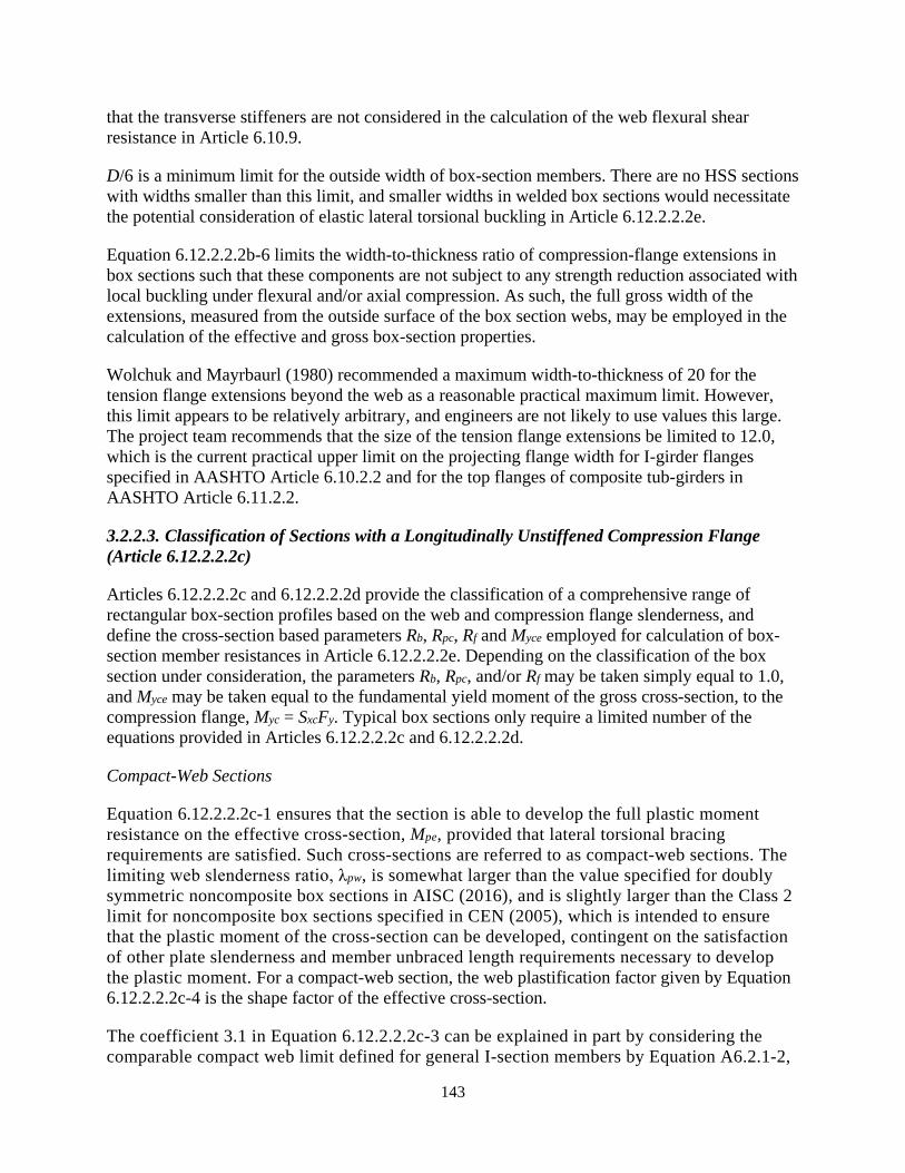
143
that the transverse stiffeners are not considered in the calculation of the web flexural shear resistance in Article 6.10.9.
D/6 is a minimum limit for the outside width of box-section members. There are no HSS sections with widths smaller than this limit, and smaller widths in welded box sections would necessitate the potential consideration of elastic lateral torsional buckling in Article 6.12.2.2.2e.
Equation 6.12.2.2.2b-6 limits the width-to-thickness ratio of compression-flange extensions in box sections such that these components are not subject to any strength reduction associated with local buckling under flexural and/or axial compression. As such, the full gross width of the extensions, measured from the outside surface of the box section webs, may be employed in the calculation of the effective and gross box-section properties.
Wolchuk and Mayrbaurl (1980) recommended a maximum width-to-thickness of 20 for the tension flange extensions beyond the web as a reasonable practical maximum limit. However, this limit appears to be relatively arbitrary, and engineers are not likely to use values this large. The project team recommends that the size of the tension flange extensions be limited to 12.0, which is the current practical upper limit on the projecting flange width for I-girder flanges specified in AASHTO Article 6.10.2.2 and for the top flanges of composite tub-girders in AASHTO Article 6.11.2.2.
3.2.2.3. Classification of Sections with a Longitudinally Unstiffened Compression Flange (Article 6.12.2.2.2c)
Articles 6.12.2.2.2c and 6.12.2.2.2d provide the classification of a comprehensive range of rectangular box-section profiles based on the web and compression flange slenderness, and define the cross-section based parameters Rb, Rpc, Rf and Myce employed for calculation of box-section member resistances in Article 6.12.2.2.2e. Depending on the classification of the box section under consideration, the parameters Rb, Rpc, and/or Rf may be taken simply equal to 1.0, and Myce may be taken equal to the fundamental yield moment of the gross cross-section, to the compression flange, Myc = SxcFy. Typical box sections only require a limited number of the equations provided in Articles 6.12.2.2.2c and 6.12.2.2.2d.
Compact-Web Sections
Equation 6.12.2.2.2c-1 ensures that the section is able to develop the full plastic moment resistance on the effective cross-section, Mpe, provided that lateral torsional bracing requirements are satisfied. Such cross-sections are referred to as compact-web sections. The limiting web slenderness ratio, λpw, is somewhat larger than the value specified for doubly symmetric noncomposite box sections in AISC (2016), and is slightly larger than the Class 2 limit for noncomposite box sections specified in CEN (2005), which is intended to ensure that the plastic moment of the cross-section can be developed, contingent on the satisfaction of other plate slenderness and member unbraced length requirements necessary to develop the plastic moment. For a compact-web section, the web plastification factor given by Equation 6.12.2.2.2c-4 is the shape factor of the effective cross-section.
The coefficient 3.1 in Equation 6.12.2.2.2c-3 can be explained in part by considering the comparable compact web limit defined for general I-section members by Equation A6.2.1-2,

144
which is illustrated in Fig. CA6.2.1-1. The form of Equation A6.2.1-2 corresponding to 2Dc/tw, Equation A6.2.2-6, appears in Table B4.1 of the AISC (2016) Specification. For I-sections with Mp/RhMy = 1.12, Equation A6.2.1-2 gives a coefficient of 3.77, which is essentially the coefficient corresponding to the compact web limit specified in Equation 6.10.6.2.2-1. This coefficient is a reasonable median value for rolled I-section members and welded doubly symmetric I-section members with comparable proportions. However, for I-sections with Mp/RhMy = 1.21, Equation A6.2.1-2 gives a coefficient of 3.1. The ratio Mp/RhMy = 1.21 is more representative of box-section members with webs proportioned near the compact limit. In addition, the coefficient 3.1 in Equation 6.2.2.2.2c-3 reflects the restraint conditions provided to the webs by the flanges in box-section members. The use of the ratio (Dce/Dcpe) in Equation 6.12.2.2.2c-3 is similar to the use of (Dc/Dcp) in Equation A6.2.2-6. This ratio converts the compact web limit to a value that corresponds to a consistent definition of the web slenderness of 2Dce/tw, which is employed with the web compact and noncompact limits in defining the web plastification factor, Rpc, in Equation 6.12.2.2.2c-7.
Effective Cross-Section
Equation 6.12.2.2.2c-1 and the subsequent equations specified in Article 6.12.2.2.2c are expressed generally in terms of the effective cross-section, considering the post-buckling response of a slender compression flange. Box-section compression flanges, which are supported by webs along two longitudinal edges, have substantial post-buckling resistance. However, unlike I-section members, where the flange local buckling resistance is limited to incipient theoretical flange local buckling, an interaction exists between the post-buckling response of the compression flange and the other strength limit states of the member. This behavior is captured by the use of the effective cross-section, based on the effective width of the compression flange, in the calculation of Dce, Dcpe, Myce, and Mpe.
Simplified Calculations
The calculations associated with Equations 6.12.2.2.2c-1 through 6.12.2.2.2c-4 and the subsequent calculations in Article 6.12.2.2.2c may be simplified as follows:
• For box-sections in which the compression flange is compact, the effective width of the compression flange is equal to its gross width, and thus the calculations in Article 6.12.2.2.2c are all based on the gross box cross-section. Otherwise, the calculations in Article 6.12.2.2.2c are based on the effective section, using the effective width of the compression flange, be, calculated as specified in Article 6.9.4.2.2b with Fcr taken equal to Fyc.
• For HSS with slender flange elements, the calculation of the effective section modulus, Sxce, the corresponding yield moment, Myce, the plastic depth of web in compression, Dcpe, and the effective plastic moment, Mpe, may be determined in a manner that parallels the recommended calculation of the effective area for axial compression for these types of sections in Equation 6.9.4.2.2a-4. For example, the effective section modulus may be calculated as:

145
( ) ( )3 2/12e f e f c
xce x
b b t b b t cS S
c− + −
= − (108)
where:
cc = distance from the neutral axis of the effective cross-section to the mid-thickness of the rectangular portion of the compression flange area, considering the effective width of the slender flange and using the gross cross-section for the web (inch)
c = distance from the neutral axis of the effective cross-section to the extreme fiber of the compression flange (inch)
This avoids complications in the consideration of the HSS corners. Other variables in Equation C6.12.2.2.2c-1 are defined in Articles 6.12.2.2.2c and 6.9.4.2.2a.
• For doubly-symmetric box-section members, a conservative estimate of the nominal flexural resistance may be obtained by using the effective width for both the compression and the tension flange in the calculation of the effective section properties. This maintains symmetry of the cross-section and thus simplifies the calculations. For singly-symmetric
box-section members, the shift in the neutral axis should be accounted for in the calculation of the effective section properties.
Consideration of Early Yielding in Tension, Homogeneous Cross-Sections
The limit state of tension flange yielding does not apply to box-section members with a longitudinally unstiffened compression flange. Instead, in cases where Sxte < Sxce, early nominal yielding in tension is to be considered in the calculation of Dce and Myce. Figure 23 illustrates the stress state corresponding to these variables for a hybrid cross-section with a compression flange having an effective width less than its actual width, indicated by the black shaded area in the figure. For a homogeneous cross-section, Fyf is equal to Fyw, giving the stress distribution represented by the light grey lines if the flexural strain distribution were the same as in the hybrid case. For a homogeneous cross-section, the following closed-form expression for the depth of the web in compression is obtained based on a rigorous strain-compatibility analysis:
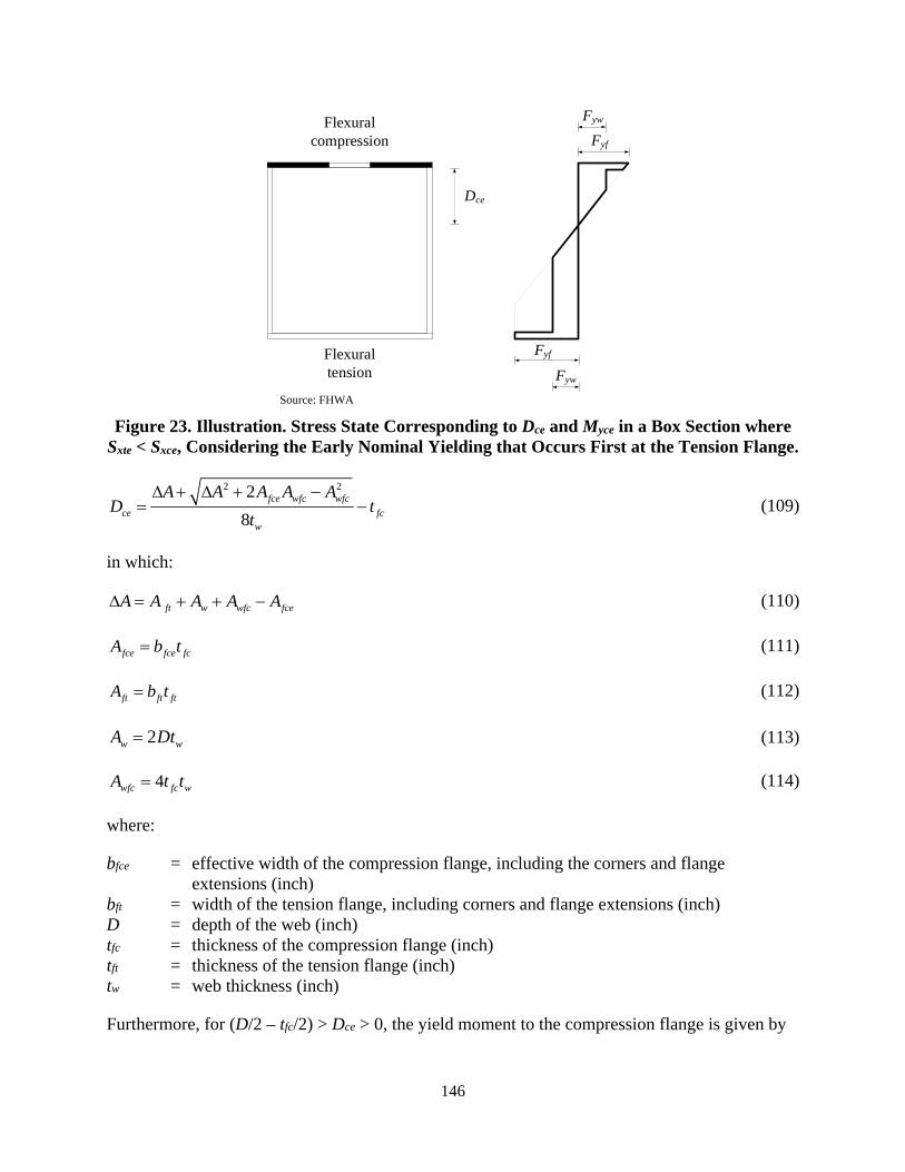
146
Source: FHWA
Figure 23. Illustration. Stress State Corresponding to Dce and Myce in a Box Section where Sxte < Sxce, Considering the Early Nominal Yielding that Occurs First at the Tension Flange.
2 228
fce wfc wfcce fc
w
A A A A AD t
t∆ + ∆ + −
= − (109)
in which:
ft w wfc fceA A A A A∆ = + + − (110)
fce fce fcA b t= (111)
ft ft ftA b t= (112)
2w wA Dt= (113)
4wfc fc wA t t= (114)
where:
bfce = effective width of the compression flange, including the corners and flange extensions (inch)
bft = width of the tension flange, including corners and flange extensions (inch) D = depth of the web (inch) tfc = thickness of the compression flange (inch) tft = thickness of the tension flange (inch) tw = web thickness (inch)
Furthermore, for (D/2 – tfc/2) > Dce > 0, the yield moment to the compression flange is given by
FywFlexural compression
Flexural tension Fyw
Fyf
Fyf
Dce
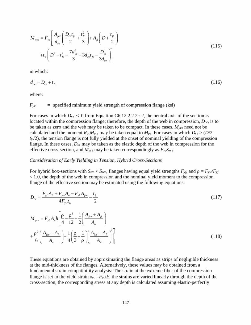
147
2
2 32 2
2 3 2
7 33 3
fce ce fc fc ftyce yc ft
ce
ce cew fc ce fc
ce
A D t t tM F A D
d
d Dt D t d td
= + + +
+ − − + −
(115)
in which:
ce ce fcd D t= + (116)
where:
Fyc = specified minimum yield strength of compression flange (ksi)
For cases in which Dce ≤ 0 from Equation C6.12.2.2.2c-2, the neutral axis of the section is located within the compression flange; therefore, the depth of the web in compression, Dce, is to be taken as zero and the web may be taken to be compact. In these cases, Myce need not be calculated and the moment RpcMyce may be taken equal to Mpe. For cases in which Dce > (D/2 – tfc/2), the tension flange is not fully yielded at the onset of nominal yielding of the compression flange. In these cases, Dce may be taken as the elastic depth of the web in compression for the effective cross-section, and Myce may be taken correspondingly as FycSxce.
Consideration of Early Yielding in Tension, Hybrid Cross-Sections
For hybrid box-sections with Sxte < Sxce, flanges having equal yield strengths Fyf, and ρ = Fyw/Fyf < 1.0, the depth of the web in compression and the nominal yield moment to the compression flange of the effective section may be estimated using the following equations:
4 2yf ft yw w yf fce fc
ceyw w
F A F A F A tD
F t+ −
= − (117)
3
22
14 12 2
1136 4
fce ftyce yf w
w
fce ft fce ft
w w
A AM F A h
A
A A A AA A
+ ρ ρ= − +
− − ρρ + + − ρ
(118)
These equations are obtained by approximating the flange areas as strips of negligible thickness at the mid-thickness of the flanges. Alternatively, these values may be obtained from a fundamental strain compatibility analysis: The strain at the extreme fiber of the compression flange is set to the yield strain εyc =Fyc/E, the strains are varied linearly through the depth of the cross-section, the corresponding stress at any depth is calculated assuming elastic-perfectly
148
plastic material response, and variation in the strains and stresses through the depth are solved iteratively for the solution that gives zero total axial force.
When Myce is calculated using Equation 118 based on the cross-section model illustrated in Figure 23, or directly via a fundamental strain-compatibility analysis, the influence of the hybrid web is included directly in the calculation of Myce. As such, Rh is to be taken equal to 1.0.
Consideration of Early Yielding in Tension, Sections with Web Longitudinal Stiffeners
For box sections with Sxte < Sxce, simple closed-form equations that include the contribution of web longitudinal stiffeners to Dce and Myce are not available. Therefore, in lieu of determining Dce and Myce from a rigorous strain-compatibility analysis, it is recommended that web longitudinal stiffeners be neglected in the calculation of these variables for these types of sections.
Consideration of Web Longitudinal Stiffeners in General
Except as specified above and in Article 6.12.2.2.2d, web longitudinal stiffeners, if present, should be included in the calculation of Myce and Sxce; however, any longitudinal stiffeners subjected to compression should be neglected in the computation of Mpe. This is due to the limited ability of longitudinal stiffeners to develop larger inelastic strains necessary to develop yielding throughout the depth of the cross-section. Any enhancement of the resistance of compact or noncompact web sections due to the placement of web longitudinal stiffeners subjected to compression, other than the increase in Myce, is neglected in these provisions. The section may be classified according to the web slenderness as specified in Articles 6.12.2.2.2c and 6.12.2.2.2d, as applicable, without considering the web longitudinal stiffeners. Web longitudinal stiffeners should be included in the calculation of the elastic gross and effective cross-section properties. In general, these cross-section elements provide a small but measurable contribution to the elastic cross-section properties and to the effective yield moment values. To be included in the calculation of the section properties, the longitudinal stiffener must be structurally continuous at the ends of interior web panels. At end panels or member ends, the longitudinal stiffener should be structurally continuous at one end and positively attached to the diaphragm at the other end.
Noncompact-Web Sections
Equation 6.12.2.2.2c-6 defines the slenderness limit for a box-section noncompact web. This limit assumes simply-supported boundary conditions at the web-flange juncture, and is the same as the limit given by Equation 6.10.6.2.3-1 for I-sections in cases where the area of the I-section flanges is small relative to the web area. This limit is slightly larger than the Class 3 limit for noncomposite box sections specified in CEN (2005), which is intended to ensure that the yield moment of the cross-section can be developed, contingent on the satisfaction of other necessary plate slenderness and unbraced length requirements. Webs with a slenderness ratio exceeding this limit are termed slender. Sections with slender webs may rely upon significant web post bend-buckling resistance at the strength limit state.
For noncompact web sections, Equation 6.12.2.2.2c-7 accounts for the influence of the web slenderness on the nominal flexural resistance. As 2Dce/tw approaches the noncompact web

149
slenderness limit, λrw, the maximum potential value of the nominal flexural resistance – commonly referred to as the plateau strength – approaches RfRhMyce. Equation 6.12.2.2.2c-7 defines a web plastification factor that provides a smooth transition in the plateau strength from RfRhMyce to RfMpe as 2Dce/tw varies from λrw to the compact web slenderness limit.
Slender-Web Sections
The plateau strength of a slender web section is RbRfRhMyce; the term Rb is discussed below.
Several simplifications may be applied for the slender-web member calculations in many cases:
• The term, Rpc, simplifies to Rh for a slender-web hybrid box section;
• The term, Rpc, simplifies to 1.0 for a slender-web homogeneous box section, and;
• The term, Rf, simplifies to 1.0 and Myce simplifies to Myc if the box section has a compact flange.
Furthermore, the slender web box-section provisions may be applied conservatively, with Rb taken equal to 1.0, for any noncompact- or compact-web box section.
For compact and noncompact web sections, theoretical web bend buckling does not occur for moment levels up to the limit of the flexural resistance. Therefore, the web load-shedding factor, Rb, is simply equal to 1.0 for these sections. For sections containing a compact compression flange and a compact web, the Article 6.12.2.2.2e plateau resistance RbRpcRfMyce is simply equal to Mp. For slender web sections, Rb is to be calculated as specified in Article 6.12.2.2.2c to account for the reduction in the section flexural resistance caused by the shedding of stresses to the compression flange due to bend buckling of the slender web.
Members with Longitudinally Stiffened Webs
For members with one or more longitudinal web stiffeners placed at ds/Dce approaching 0.76 or larger, where ds is the distance from the centerline of the closest longitudinal stiffener to the inner surface of the compression flange, the value of Rb determined from the provisions of Article 6.10.1.10.2 tends to be relatively small since these provisions neglect the impact of web longitudinal stiffeners on the web bend buckling response for ds/Dce ≥ 0.76. These proportions are common in some types of columns and arch ribs. In addition, in narrow box sections, the value of awce employed in the calculation of Rb can be relatively large. The Rb equation tends to be conservative in these situations. In these cases, a larger plateau strength may be determined by using a strain-compatibility analysis considering an effective width of the longitudinally stiffened webs, as discussed in Lokhande and White (2018).
Compact-Flange Sections
Box-section flanges that satisfy the nonslender limit in uniform axial compression specified in Article 6.9.4.2.1 are defined as compact in Article 6.12.2.2.2c. For welded built-up box sections, λpf as specified by these provisions is comparable to the compact flange limit in AISC (2016), and it is comparable to the Class 1 flange limit in CEN (2005), which is intended to ensure that
150
the section can form a plastic hinge with a rotation capacity sufficient for plastic analysis, contingent on the satisfaction of other necessary plate slenderness and unbraced length requirements. This more restrictive limit is also related to the shift in Winter’s classical plate effective width curve for welded built-up box sections discussed in Article C6.9.4.2.2b. For cold-formed HSS, λpf as specified by these provisions is comparable to the Class 2 flange limit in CEN (2005), which is intended to ensure that the plastic moment of the cross-section can be developed, contingent on the satisfaction of other plate slenderness and member unbraced length requirements necessary to develop the plastic moment. For non-welded built-up box sections and hot-formed HSS, λpf as specified by these provisions is slightly larger than the Class 2 flange limit in CEN (2005).
Compression Flange Slenderness Factor, Rf, Noncompact- and Slender-Flange Sections
Box-section members with longitudinally unstiffened compression flanges traditionally classified in the AISC and AASHTO provisions as noncompact are capable of developing a flexural resistance close to the cross-section full plastic moment, Mp, if the webs are compact according to the classifications specified in Article 6.12.2.2.2c and the member is adequately braced (Lokhande and White, 2018). Box sections with a compression flange slenderness larger than the compact flange limit given by Equation 6.12.2.2.2c-9 have a compression flange effective width smaller than the gross width of the flange, as well a compression flange slenderness factor, Rf, smaller than 1.0.
The compression flange slenderness factor, Rf, accounts for reductions in the plateau strength of noncompact and slender flange box sections due to the limited ability of these types of flanges to (1) develop larger inelastic strains necessary to achieve yielding through the depth of the cross-section, and (2) to accept the stresses shed to them due to bend buckling of a slender web. These reductions are in addition to the reductions associated with the compression flange effective width as well as the web-based parameters Rb and Rpc. Lokhande and White (2018) found that the reductions in the flexural resistance of these types of box-section members is represented with good accuracy by Equations 6.12.2.2.2c-12 through 6.12.2.2.2c-16.
For compact-flange box sections, the term Rf is taken simply equal to 1.0.
3.2.2.4. Classification of Sections with a Longitudinally Stiffened Compression Flange (Article 6.12.2.2.2d)
Longitudinally stiffened box-section compression flanges are generally unable to withstand inelastic deformations necessary to develop significant yielding throughout the depth of the box section webs without significant reductions in their compressive resistance. Hence, the largest possible flexural resistance of these types of members is limited to the effective yield moment, Myce, which corresponds to the development of the maximum compressive resistance of the longitudinally stiffened compression flange. As such, box sections with longitudinally stiffened compression flanges are in effect handled as slender web sections.
In cases where flange longitudinal stiffeners are provided but are not required for strength, the longitudinal stiffeners may be neglected and the flange may be considered as longitudinally

151
unstiffened for purposes of calculating the member strength. However, all requirements pertaining to the longitudinal stiffeners shall be satisfied for such sections.
The limit state of tension flange yielding does not apply to box section members with a longitudinally stiffened compression flange. Instead, in cases where Sxte < Sxce, early nominal yielding in tension is to be considered in the calculation of Dce and Myce. Figure 23 illustrates the stress state corresponding to these variables for a hybrid cross-section with a longitudinally unstiffened compression flange. For a homogeneous cross-section, Fyf is equal to Fyw. In lieu of a more rigorous strain-compatibility analysis, this idealized model, and the corresponding equations in Section 3.2.2.3, may be employed for calculating the Dce and Myce of a box section with a longitudinally stiffened compression flange by: (1) substituting the effective compression flange area, Aeff, determined using Equation 6.12.2.2.2d-1, for Afce; (2) modeling the effective compression flange area as a zero-thickness strip located at the centroid of the gross compression flange area including the longitudinal stiffeners; (3) taking tfc as zero inches in the last term of Equation 109; (4) taking the web depth as the depth between the effective compression flange elevation and the elevation of a zero-thickness strip representing the tension flange area and located at the centroid of the tension flange; and (5) neglecting any web longitudinal stiffeners.
When applying Equation 109 to a box section with a longitudinally stiffened flange, if a negative value of Dce is obtained, the effective compression flange is relatively large. In this case, the neutral axis of the cross-section corresponding to the nominal first yielding of the idealized zero-thickness strip representing the compression flange is located at the centroid of the effective compression flange. For this extreme case, the strains at the compression flange will be relatively small and essentially the entire cross-section below the compression flange will be yielded in tension at the onset of nominal first yielding of the compression flange. Therefore, Myce may be taken equal to the plastic moment of the effective cross-section, Mpe, for this case. The inelastic deformation of the compression flange needed to develop this flexural resistance is relatively small and can be accommodated by the longitudinally stiffened compression flange. Also, the webs of the box section are loaded entirely in tension at the onset of nominal first yielding of the compression flange, and therefore web local buckling is not a consideration.
Rf is simply taken equal to 1.0 in sections with longitudinally stiffened compression flanges; the calculation of the effective area of the compression flange quantifies the flexural resistance of these types of box-section members accurately to conservatively without any further reduction (Lokhande and White, 2018).
3.2.2.5. General Yielding, Compression Flange Local Buckling and Lateral Torsional Buckling (Article 6.12.2.2.2e)
Equations 6.12.2.2.2e-1 and 6.12.2.2.2e-2 quantify the nominal flexural resistance considering the combined effects of general yielding, compression flange local buckling, and lateral torsional buckling. For longitudinally unstiffened box sections satisfying the cross-section proportion limits of Article 6.12.2.2.2b, the limiting unbraced length Lp for members with D/bfo ≤ 2.0 is always larger than 6D. In addition, the limiting unbraced length Lr for these types of members is commonly larger than 70D. As such, the reduction in the flexural resistance under uniform bending is never more than approximately 10 percent for longitudinally unstiffened box-section members with D/bfo ≤ 2.0 and Lb/D ≤ 20 that satisfy the cross-section proportion limits of
152
Article 6.12.2.2.2b. The maximum reduction in the flexural resistance under uniform bending is approximately one-half of this value, i.e., five percent, for members with D/bfo ≤ 2.0 and Lb/D ≤ 10. Members that have stocky compression and tension flanges combined with webs proportioned at the maximum limit of Equation 6.12.2.2.2b-1 exhibit the largest reduction in strength associated with the lateral torsional buckling limit state. In designs where the moment gradient modifier Cb is greater than 1.10, this reduction is nonexistent.
For longitudinally stiffened box sections satisfying the cross-section proportion limits of Article 6.12.2.2.2b, the limiting unbraced length Lp for members with D/bfo ≤ 2.0 is always larger than 4D. In addition, the limiting unbraced length Lr for these types of members is commonly larger than 50D. As such, the reduction in the flexural resistance under uniform bending is never more than approximately 20 percent for members with D/bfo ≤ 2.0 and Lb/D ≤ 20 that satisfy the cross-section proportion limits of Article 6.12.2.2.2b. The maximum reduction in the flexural resistance under uniform bending is approximately one-half of this value, i.e., 10 percent, for members with D/bfo ≤ 2.0 and Lb/D ≤ 10. Members that have stocky compression and tension flanges combined with webs proportioned at the maximum limit of Equation 6.12.2.2.2b-1 exhibit the largest reduction in strength associated with the lateral torsional buckling limit state. In designs where the moment gradient modifier Cb is greater than 1.20, this reduction is nonexistent.
The limiting unbraced length Lr is commonly larger than the largest practical unbraced length, taken as the smaller of 30D and 200ry, for all box sections satisfying the cross-section proportion limits of Article 6.12.2.2.2b. Therefore, elastic lateral torsional buckling need not be considered for all practical noncomposite box section members. Equation 6.12.2.2.2e-2 may be employed to calculate the resistance for any extreme situations where Lb > Lr.
Lp given by Equation 6.12.2.2.2e-4 is the same as the corresponding limiting length for box sections given in the corresponding AISC (2016) provisions with the exception that the plastic moment, Mp, is estimated as 1.3Myce in Article 6.12.2.2.2e. The bracing requirements to reach the lateral torsional buckling plateau strength given by Equation 6.12.2.2.2e-1 are comparable for all types of box-section members, irrespective of whether the cross-section is capable of developing the plastic moment Mp or not (Lokhande and White, 2018). For general box-section members, it may be stated that Equation 6.12.2.2.2e-4 is based on the theoretical length corresponding to an elastic lateral torsional buckling resistance of (1.3)(15)Myce = 20Myce. Therefore, as a general rule, if the elastic lateral torsional buckling load is greater than 20Myce, the box section member may be checked solely for its plateau strength in flexure. The parameters Fyr and Lr in this article differ from the corresponding AISC provisions. These parameters have been determined based on test simulation studies conducted by Lokhande and White (2018), as well as consideration of the lateral-torsional buckling resistance predictions of other standards such as CEN (2006b). The limiting length, Lr, is taken as approximately 30 percent of the limiting length corresponding to theoretical elastic lateral torsional buckling at a compression flange stress equal to Fyr.
Equations 6.12.2.2.2e-4 and 6.12.2.2.2e-5 are derived from the fundamental equations for elastic lateral-torsional buckling of doubly symmetric rectangular box-section members. Lokhande and White (2018) show similar equations based on the rigorous theoretical elastic lateral-torsional buckling of singly-symmetric box-section members. The corresponding lateral-torsional buckling resistance predictions using the rigorously derived equations for singly-symmetric box-
153
section members are never more than one percent different from the predictions obtained by simply applying the doubly-symmetric section based equations specified in Article 6.12.2.2.2e to singly-symmetric section members. The maximum change in the limiting unbraced length, Lp, obtained by using the equations in this article, versus the rigorously derived equations for singly-symmetric box-section members, is approximately 10 percent. The maximum change in the limiting unbraced length, Lr, obtained by using the equations in this article versus the rigorously derived equations for singly-symmetric box-section members, is less than one percent. Therefore, the much simpler Lp and Lr equations derived assuming doubly symmetric cross-sections are specified to address all types of rectangular box-section members in these provisions.
It should be emphasized that the calculations in this article based on the underlying elastic lateral-torsional buckling equations always use the gross cross-section properties. These are combined with the use of the effective cross-section properties for all terms related to the yield or plastic moment resistance of the cross-section.
3.2.2.6. Service and Fatigue Limit States and Constructibility (Article 6.12.2.2.2f)
The provisions of Article 6.10.3.3 investigate the webs for the shear due to the factored load for constructibility specified in Article 3.4.2.1. The nominal shear resistance for this check is limited to the shear-yielding or shear-buckling resistance, Vcr. The use of tension-field action is not permitted under this load during construction.
The provisions of Article 6.10.5.3 are intended to alleviate any significant elastic flexing of the webs due to shearing actions under the unfactored permanent load plus the Fatigue I load combination. The shear is also limited in this case to Vcr to ensure that the member is able to sustain an infinite number of loadings without fatigue cracking due to this effect.
For box-section members subject to torsion, web shear yielding or shear buckling should be checked according to the provisions of Articles 6.10.3.3 and 6.10.5.3 for the critical web subjected to additive flexural and torsional shear. Shear yielding or shear buckling of the flange plates in box-section members need not be checked because the flange torsional shears are generally small at these limit states and such a check is unlikely to control. Also, flange shear stresses due to flexure, which are tangent to the wall of the flange plate, are maximum at the connection to the webs, zero at a location within the middle of the plate, and the net shear force in the flanges is zero.
Web longitudinal stiffeners are ignored in the calculation of the web shear yielding or shear buckling resistance, Vcr.
Since post-buckling resistance is assumed at the strength limit state in computing the nominal flexural resistance of box-section members with slender webs, box sections containing slender longitudinally stiffened plate panels, and/or box sections with a noncompact or slender longitudinally unstiffened compression flange, such members must also satisfy the provisions of Article 6.9.4.5 to ensure that plate local buckling due to flexural stresses does not occur theoretically at the service limit state and for constructibility. Plate local buckling is not checked at the fatigue limit state in Article 6.9.4.5 because the plate buckling check under the Service II
154
loads will tend to control over a similar check under the unfactored permanent load plus the Fatigue I load combination.
For box-section members subjected to combined axial and flexural stresses, Article 6.9.4.5 checks plate local buckling directly for the combined stress state.
3.2.2.7. Consideration of Shear Lag Effects (Article 6.12.2.2.2g)
This article provides simplified rules requiring the consideration of shear lag effects only for cases where the effective span, Leff, is less than 5bfi, with the exception of the calculation of elastic flexural stresses under service and fatigue limit states within cantilevers and within the negative moment regions of continuous-span members. In many practical situations, there is no reduction in the flange effective width due to shear lag. The reductions in flange effectiveness due to shear lag are more significant for cantilevers and negative moment regions at these limit states. Where required, the reductions on the compression flange effective width, be, the compression flange effective area, Aeff, and the tension flange gross area, as applicable, are applied in a simplified manner as a uniform reduction for all the cross-sections within the effective span of the member under consideration. These reductions are employed only for the purpose of determining cross-section resistances at the strength limit states, or cross-section stresses at the service and fatigue limit states. They are not intended as reductions to be applied within the bridge structural analysis.
For the consideration of shear lag effects at the strength limit state, the requirements specified Article 6.12.2.2.2g are comparable to the Article 4.6.2.6.4 requirements specified for orthotropic steel decks, which recognize the benefits of inelastic redistribution of flange stresses. For the consideration of shear lag effects under service and fatigue limit states, the requirements specified in this article also recognize that the reduction in the flange effectiveness in simple-span members and within the positive moment regions of continuous-span members tends to be relatively small, and may be neglected as a coarse approximation, as long as the flange width, bfi, is below the Leff/5 limit. However, the reduction in the elastic flange effectiveness reduction for cantilevers and for negative moment regions of continuous spans tends to be more significant. Equations 6.12.2.2.2g-2 and 6.12.2.2.2g-3 are a fit to the curve provided by FHWA (1980) and Wolchuk (1997) for longitudinally unstiffened flanges, which is in turn based largely on the work by Moffatt and Dowling (1975, 1976). FHWA (1980) and Wolchuk (1997) recommend a reduction factor for longitudinally stiffened flanges that is up to 10 percent smaller than the value recommended for longitudinally unstiffened flanges. In lieu of a more refined calculation, it is specified that the values given by Equations 6.12.2.2.2g-2 and 6.12.2.2.2g-3 be multiplied by 0.9 for longitudinally stiffened flanges. The requirements specified in Article 6.12.2.2.2g assume that flange extensions are sufficiently narrow such that they are fully effective with respect to shear lag, based on the compactness requirements of Equation 6.12.2.2.2b-6. Positive and negative bending regions are defined in this article based on the distance between the inflection points in positive or negative bending under the component dead load.
Figure 24 plots Equations 6.12.2.2.2a-1 and 2 along with a number of other representative curves quantifying the shear lag reduction factor, ψ, for the flange width or flange area. The abscissa is the ratio of the effective span length to the box-section flange width, Leff /bfi. The following
155
curves are shown in the plot, progressing from the top to the bottom curves within the mid-length of the plot:
• The recommended shear lag reduction at strength limit states and for positive bending under elastic stress conditions is given by the thin grey curve, i.e., no reduction for Leff/bfi > 5 and a relatively sharp reduction for smaller Leff /bfi values.
• The corresponding positive (sagging) moment Eurocode shear lag reduction at the “Ultimate Limit State (ULS),” i.e., at strength limit states, is shown by the bold grey curve with circular grey symbols.
• A hypothetical shear lag reduction obtained by applying the Eurocode specified mapping of its elastic shear lag curves to its ULS shear lag curves (explained below) to Equations 6.12.2.2.2g-2 and 3 is shown by the bold solid grey curve.
• The Eurocode negative (hogging) moment shear lag reduction at the Ultimate Limit State, also applicable to cantilever spans, is shown by the dashed grey curve.
• The Eurocode positive (sagging) moment shear lag reduction under elastic stress conditions is shown by the bold black curve with the circular black symbols.
• The elastic shear lag reduction recommended by Equations 6.12.2.2.2g-2 and 3 for the negative (hogging) moment region of continuous spans, and for cantilevers, is illustrated by the bold solid black curve. As noted above, this is a fit to the curve provided by Wolchuk and Mayrbaurl (1980) for longitudinally unstiffened flanges.
• The corresponding Eurocode curve for the elastic shear lag reduction at the pier location in hogging moment regions, and at cantilever span supports, is shown by the black dashed curve.

156
Source: FHWA
Figure 24. Chart. Box-section flange effective width reduction factors.
The Eurocode elastic curves are illustrative of other elastic shear lag curves that can be found in the literature. For instance, BS5400:3 (BSI, 2000) gives similar, but different, elastic shear lag curves for the cases shown. Corresponding to the smaller shear lag reduction factor corresponding to hogging moment regions and cantilevers, BS5400 gives three curves, one for the hogging moment region of interior spans that is slightly more optimistic than the Eurocode curve, and two additional curves, one for cantilever spans and one for propped cantilevers that are somewhat less optimistic than the Eurocode curve. Yu (2000) reviews a range of elastic shear lag reduction factors for cantilevers, developed by Hildebrand and Reissner (1943), indicating larger values for the shear lag reduction factor.
Eurocode 3 Part 1-5 specifies a relatively simple mapping from its elastic shear lag reduction factors to its ULS shear lag reduction factors of
( / )fi effb LULS EL ELψ = ψ ≥ ψ (119)
157
for the members having longitudinally unstiffened flanges. That is, the ULS shear lag reduction factor is taken as the elastic shear lag reduction factor raised to the power (bfi/Leff).
These curves illustrate the following points:
(1) If the Eurocode ULS curve for the positive (sagging) moment regions is accepted as a reasonable approximation, then the maximum unconservative error in the flange effective width for these cases obtained by neglecting the shear lag reduction for all values of Leff/bfi > 5 is approximately 5 %.
(2) If the Eurocode mapping from the elastic to the ULS shear lag reduction factor is considered accurate, and if Equations 6.12.2.2.2g-2 and 3 are assumed to accurately describe the elastic shear lag reduction factor for negative (hogging) moment regions and cantilevers, then the maximum unconservative error in the flange effective width obtained for the negative (hogging) moment and cantilever ULS cases by neglecting the shear lag reduction for all values of Leff/bfi > 5 is approximately 10 %.
(3) If the Eurocode ULS curve for the negative (hogging) moment regions and cantilevers is assumed to accurately describe the shear lag reduction for these cases, then the maximum unconservative error in the flange effective width obtained for the negative (hogging) moment and cantilever ULS cases by neglecting the shear lag reduction for all values of Leff/bfi > 5 is approximately 15 %.
(4) If the Eurocode elastic shear lag reduction for sagging (positive) moment regions is assumed to accurately describe the shear lag reduction for these cases, then the maximum unconservative error in the flange effective width obtained for these cases by neglecting the shear lag reduction for all values of Leff/bfi > 5 is approximately 20 %.
(5) Clearly, there is a significant reduction in the flange effective width for the elastic negative (hogging) moment and cantilever cases. If the Eurocode curve is assumed to be the accurate representation for these cases, the maximum unconservative error in the flange effective width obtained using the recommended shear lag reduction curve for all values of Leff/bfi > 5 is approximately 30 %.
The curves from Wolchuk and Mayrbaurl (1980) and Wolchuk (1997) are recommended in this work to represent the shear lag reduction effects on box-section member flanges within the negative moment region of continuous spans, and for cantilevers. These curves are captured by Equations 6.12.2.2.2g-2 and 3 along with the recommended multiplication of the result from these curves by 0.9 when the flange is longitudinally stiffened. The simple shear lag reduction from Articles 6.11.1 and 4.6.2.6.4 is recommended for other cases.
For special structures employing box-section members with unusually wide flanges compared to the effective span, the Engineer may wish to conduct refined analyses to obtain a more accurate accounting of shear lag effects. Full nonlinear analyses including the effect of residual stresses are necessary to capture the influence of inelastic stress redistribution on the flange effective widths at the strength limit state, which may be prohibitive for more routine bridge designs.

158
3.2.2.8. Miscellaneous Flexural Member Provisions (Article 6.12.1.2)
These provisions provide the call-outs to the provisions defining the various limit state calculations for the different member types addressed by Article 6.12. Article 6.12.1.2.1 addresses the flexural resistance limit states. Article 6.12.1.2.2 addresses combined flexure, axial load and torsion, providing call-outs to Articles 6.8.2.3 and 6.9.2.2. Article 6.12.1.2.3 defines the limit state checks for flexural and torsional shear.
These provisions assume low or zero levels of axial force in the member and uniaxial flexure. For members that are also subject to a factored concentrically-applied axial force, Pu, in excess of five percent of the factored axial resistance of the member, Pr or Pry, as applicable, at the strength limit state, and/or if the member is subject to biaxial bending and/or torsion, the member should instead be checked according to the provisions of Article 6.8.2.3 or 6.9.2.2, as applicable. The level of five percent is based conservatively on the linear interaction equations given in these articles, which apply in the majority of cases. Below this level, it is reasonable to ignore the effect of the axial force in the design of the member.
3.3. FORCE INTERACTION
3.3.1. Specification Provisions (Articles 6.9.2.2 and 6.8.2.3)
6.9.2.2—Combined Axial Compression, Flexure, and Flexural and/or Torsional Shear
6.9.2.2.1−General
Except as permitted otherwise in Articles 6.9.4.4 and 6.9.6.3, the factored moments, Mux and Muy, and factored axial compressive load, Pu, calculated by elastic analysis shall satisfy the following relationships, as applicable, with all ratios taken as positive:
• For members in which all of the cross-section elements are defined as compact for flexure according to the provisions of Articles A6.2.1, A6.3.2, 6.11.6.2.2, and 6.12.2.2.2c, as applicable:
If Pu /Pr < 0.2, then o
1.02
uyu ux
r rx ry
MP M P M M
+ + ≤ (6.9.2.2.1-1)
o If Pu /Pr > 0.2, then
8 1.09
uyu ux
r rx ry
MP M P M M
+ + ≤
(6.9.2.2.1-2)
• The following may be employed for all types of members:
1.0uyu ux
r rx ry
MP M P M M
+ + ≤ (6.9.2.2.1-3)
159
where:
Pr = factored compressive resistance as specified in Article 6.9.2.1 (kip) Pu = factored compressive axial force (kip) Mrx = factored flexural resistance about the x-axis taken equal to φf times the nominal
flexural resistance about the x-axis determined as specified in Article 6.10, 6.11 or 6.12, as applicable, excluding tension flange rupture (kip-inch)
Mry = factored flexural resistance about the y-axis taken equal to φf times the nominal flexural resistance about the y-axis determined as specified in Article 6.12, as applicable, excluding tension flange rupture (kip-inch)
Mux = factored moment about the x-axis calculated as specified below (kip-inch) Muy = factored moment about the y-axis calculated as specified below (kip-inch) φf = resistance factor for flexure specified in Article 6.5.4.2
The moments, Mux and Muy, shall be determined by:
• a second-order elastic analysis that accounts for the magnification of moment caused by the factored axial load, or
• the approximate single-step adjustment method specified in Article 4.5.3.2.2b, or a comparable amplification factor based procedure.
For sections where the nominal flexural resistance about the major axis of the section is expressed in terms of stress, the factored flexural resistance about that axis in Eqs. 6.9.2.2.1-1 through 6.9.2.2.1-3 should be taken as:
M rx = the smaller of φ φf FncSxc and f Fnt Sxt (6.9.2.2.1-4)
where:
Fnc = nominal flexural resistance of the compression flange (ksi) Fnt = nominal flexural resistance of the tension flange (ksi) Myc = yield moment with respect to the compression flange determined as specified in
Article D6.2 (kip-in.) Myt = yield moment with respect to the tension flange determined as specified in Article
D6.2 (kip-in.) Sxc = elastic section modulus about the major axis of the section to the compression flange
taken as Myc/Fyc (in.3) Sxt = elastic section modulus about the major axis of the section to the tension flange taken
as Myt/Fyt (in.3)
For sections where the nominal flexural resistance about the major axis of the section is determined according to the provisions of Appendix A6, the factored flexural resistance about that axis in Eqs. 6.9.2.2.1-1 through 6.9.2.2.1-3 should be taken as:
the smaller of andrx f nc f ntM M M= φ φ (6.9.2.2.1-5)
160
where:
Mnc = nominal flexural resistance based on the compression flange (kip-inch) Mnt = nominal flexural resistance based on the tension flange (kip-inch)
Interaction with torsional and/or flexural shear, as applicable, shall be considered as specified in Article 6.9.2.2.2.
For all cross-section plate elements that are supported along two longitudinal edges and are slender as defined in Article 6.9.4.2.2a, and for slender panels of longitudinally stiffened plates as defined in Appendix E6.1.2, the provisions of Article 6.9.4.5 also shall be satisfied.
6.9.2.2.2−Interaction with Torsional and/or Flexural Shear
For the following member types:
• noncomposite rectangular box-section members, including square and rectangular HSS, and
• noncomposite circular tubes, including round HSS,
when the member is subjected to torsion resulting in a maximum ratio of the factored torsional shear stress to the corresponding cross-section element factored shear resistance, fve/φTFcv, greater than 0.2, the factored torsional shear stresses shall be considered within the applicable strength interaction equations as specified herein.
For general members, including those specified above, where Pu/Pr is greater than 0.05, the factored flexural shear stresses shall be considered within the applicable strength interaction equations as specified herein; otherwise, the factored flexural shear stresses need not be considered.
Where the consideration of both the torsional and flexural shear stresses is required, the torsional and flexural shear stresses shall be summed based on their corresponding directions in each of the plate elements of the cross-section, given the internal loadings. Where either of the above exclusion conditions are met, the corresponding contributions to the shear stresses shall be taken as zero. When the corresponding flexural shear, torsional shear and/or combined shear stress, as applicable, is non-zero:
• Pr shall be multiplied by ∆,
• Mrx shall be multiplied by ∆x, and
• Mry shall be multiplied by ∆y
in Eqs. 6.9.2.2.1-1 through 6.9.2.2.1-3.
∆, ∆x, and ∆y shall be computed as follows:
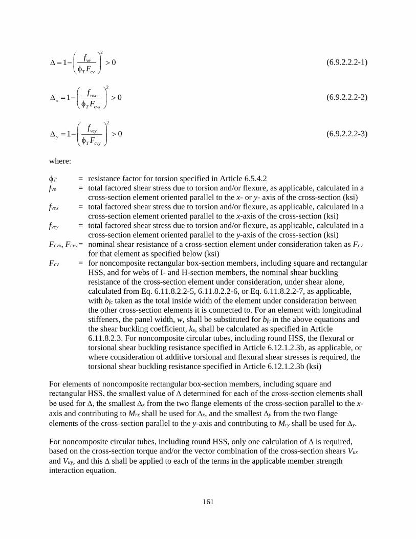
161
2
1 0ve
T cv
fF
∆ = − > φ
(6.9.2.2.2-1)
2
1 0vexx
T cvx
fF
∆ = − > φ
(6.9.2.2.2-2)
2
1 0veyy
T cvy
fF
∆ = − > φ
(6.9.2.2.2-3)
where:
ϕT = resistance factor for torsion specified in Article 6.5.4.2 fve = total factored shear stress due to torsion and/or flexure, as applicable, calculated in a
cross-section element oriented parallel to the x- or y- axis of the cross-section (ksi) fvex = total factored shear stress due to torsion and/or flexure, as applicable, calculated in a
cross-section element oriented parallel to the x-axis of the cross-section (ksi) fvey = total factored shear stress due to torsion and/or flexure, as applicable, calculated in a
cross-section element oriented parallel to the y-axis of the cross-section (ksi) Fcvx, Fcvy = nominal shear resistance of a cross-section element under consideration taken as Fcv
for that element as specified below (ksi) Fcv = for noncomposite rectangular box-section members, including square and rectangular
HSS, and for webs of I- and H-section members, the nominal shear buckling resistance of the cross-section element under consideration, under shear alone, calculated from Eq. 6.11.8.2.2-5, 6.11.8.2.2-6, or Eq. 6.11.8.2.2-7, as applicable, with bfc taken as the total inside width of the element under consideration between the other cross-section elements it is connected to. For an element with longitudinal stiffeners, the panel width, w, shall be substituted for bfc in the above equations and the shear buckling coefficient, ks, shall be calculated as specified in Article 6.11.8.2.3. For noncomposite circular tubes, including round HSS, the flexural or torsional shear buckling resistance specified in Article 6.12.1.2.3b, as applicable, or where consideration of additive torsional and flexural shear stresses is required, the torsional shear buckling resistance specified in Article 6.12.1.2.3b (ksi)
For elements of noncomposite rectangular box-section members, including square and rectangular HSS, the smallest value of ∆ determined for each of the cross-section elements shall be used for ∆, the smallest ∆x from the two flange elements of the cross-section parallel to the x-axis and contributing to Mrx shall be used for ∆x, and the smallest ∆y from the two flange elements of the cross-section parallel to the y-axis and contributing to Mry shall be used for ∆y.
For noncomposite circular tubes, including round HSS, only one calculation of ∆ is required, based on the cross-section torque and/or the vector combination of the cross-section shears Vux and Vuy, and this ∆ shall be applied to each of the terms in the applicable member strength interaction equation.

162
For I-section members, the cross-section shear stresses due to torque shall be neglected. For these member types, ∆x and ∆y shall be taken equal to 1.0 in all cases, and the only the flexural shear stresses in the web shall be considered in the calculation of ∆.
6.8.2.3—Combined Tension, Flexure, and Flexural and/or Torsional Shear
6.8.2.3.1 General
The factored moments, Mux and Muy, and factored axial tensile load, Pu, calculated by elastic analysis shall satisfy the relationships specified herein, as applicable, with all ratios taken as positive. In addition, the member tension rupture provisions of Article 6.8.2.3.3 shall be satisfied at welded and/or bolted connections and at cross-sections having a net area reduction due to bolt holes. Interaction with torsional and/or flexural shear, as applicable, shall be considered as specified in Article 6.8.2.3.2.
• Except as permitted herein, following relationships shall be employed for all types of members:
o If 0.2, thenu
ry
P P
<
1.02
uyu ux
ry rx ry
MP M P M M
+ + ≤
(6.8.2.3.1-1)
o If 0.2, thenu
ry
P P
≥
8 1.09
uyu ux
ry rx ry
MP M P M M
+ + ≤
(6.8.2.3.1-2)
• For noncomposite I- and box-section members, the following alternative relationships may be employed in combination:
1.0uyu ux
ry rxpe rype
MP M P M M
+ + ≤
(6.8.2.3.1-3)
1.0uyux
rxc ryc
MM M M
+ ≤
(6.8.2.3.1-4)
where:
Pry = factored tensile resistance based on tension yielding, obtained from Eq. 6.8.2.1-1 (kip)
163
Pu = factored tensile axial force (kip) Mrx = factored flexural resistance about the x-axis taken as φf times the nominal flexural
resistance about the x-axis determined as specified in Article 6.10, 6.11 or 6.12, as applicable, excluding tension flange rupture (kip-inch)
Mrxc = factored flexural resistance about the x-axis taken as φf times the nominal flexural resistance about the x-axis considering compression buckling, determined as specified in Article 6.10 or 6.12, as applicable (kip-inch)
Mrxpe = for I-section members, φf times the plastic moment about the x-axis neglecting any web longitudinal stiffeners; for noncomposite box-section members, φf times the effective plastic moment about the x-axis, based on the effective compression flange area as defined in Article 6.12.2.2.2c or 6.12.2.2.2d, as applicable, and neglecting any web longitudinal stiffeners (kip-inch)
Mry = factored flexural resistance about the y-axis taken as φf times the nominal flexural resistance about the y-axis determined as specified in Article 6.12, as applicable, excluding tension flange rupture (kip-inch)
Mryc = factored flexural resistance about the y-axis taken as φf times the nominal flexural resistance about the y-axis considering compression buckling, determined as specified in Article 6.12, as applicable; Mryc = Mryt = Mry for I-section members (kip-inch)
Mrype = for I-section members, φf times the plastic moment about the weak axis; for noncomposite box-section members, φf times the effective plastic moment about the y-axis, based on the effective compression flange area as defined in Article 6.12.2.2.2c or 6.12.2.2.2d, as applicable, and neglecting any web longitudinal stiffeners (kip-inch)
Mux, Muy = factored moments about the x- and y-axes, respectively (kip-inch) φf = resistance factor for flexure specified in Article 6.5.4.2
For all cross-section plate elements that are supported along two longitudinal edges and are slender as defined in Article 6.9.4.2.2a, and for slender panels of longitudinally stiffened plates as defined in Article E6.1.2, the provisions of Article 6.9.4.5 also shall be satisfied.
6.8.2.3.2−Interaction with Torsional and/or Flexural Shear
For the following member types:
• noncomposite rectangular box-section members, including square and rectangular HSS, and
• noncomposite circular tubes, including round HSS,
when the member is subjected to torsion resulting in a maximum ratio of the factored torsional shear stress to the corresponding cross-section element factored shear resistance, fve/φTFcv, greater than 0.2, the factored torsional shear stresses shall be considered within the applicable strength interaction equations as specified herein
For general members, including those specified above, where Pu/Pry is greater than 0.05, the factored flexural shear stresses shall be considered within the applicable strength interaction
164
equations as specified herein; otherwise, the factored flexural shear stresses need not be considered.
Where the consideration of both the torsional and flexural shear stresses is required, the torsional and flexural shear stresses shall be summed based on their corresponding directions in each of the plate elements of the cross-section, given the internal loadings. Where either of the above exclusion conditions are met, the corresponding contributions to the shear stresses shall be taken as zero. When the corresponding flexural shear, torsional shear and/or combined shear stress, as applicable, is non-zero:
• Pry shall be multiplied by ∆,
• Mrx, Mrxc and Mrxpe shall be multiplied by ∆x, and
• Mry, Mryc and Mrype shall be multiplied by ∆y,
in Eqs. 6.8.2.3.1-1 through 6.8.2.3.1-4. ϕT is the resistance factor for torsion specified in Article 6.5.4.2. ∆, ∆x, ∆y, and Fcv shall be computed as specified in Article 6.9.2.2.2.
For elements of noncomposite rectangular box-section members, including square and rectangular HSS, the smallest value of ∆ determined for each of the cross-section elements shall be used for ∆, the smallest ∆x from the two flange elements of the cross-section parallel to the x-axis and contributing to Mrx shall be used for ∆x, and the smallest ∆y from the two flange elements of the cross-section parallel to the y-axis and contributing to Mry shall be used for ∆y.
For noncomposite circular tubes, including round HSS, only one calculation of ∆ is required, based on the cross-section torque and/or the vector combination of the cross-section shears Vux and Vuy, and this ∆ shall be applied to each of the terms in the applicable member strength interaction equation.
For I-section members, the cross-section shear stresses due to torque shall be neglected. For these member types, ∆x and ∆y shall be taken equal to 1.0 in all cases, and the only the flexural shear stresses in the web shall be considered in the calculation of ∆.
6.8.2.3.3− Tension Rupture Under Axial Tension or Compression Combined with Flexure
The following locations:
• Cross-sections containing bolt holes in one or more flanges that are subjected to tension under combined axial tension or compression and flexure at connection or non-connection locations,
• Cross-sections at connection or nonconnection locations subjected to axial tension and flexure and containing bolt holes in other cross-section elements, or
• Cross-sections at welded connections subjected to axial tension and flexure
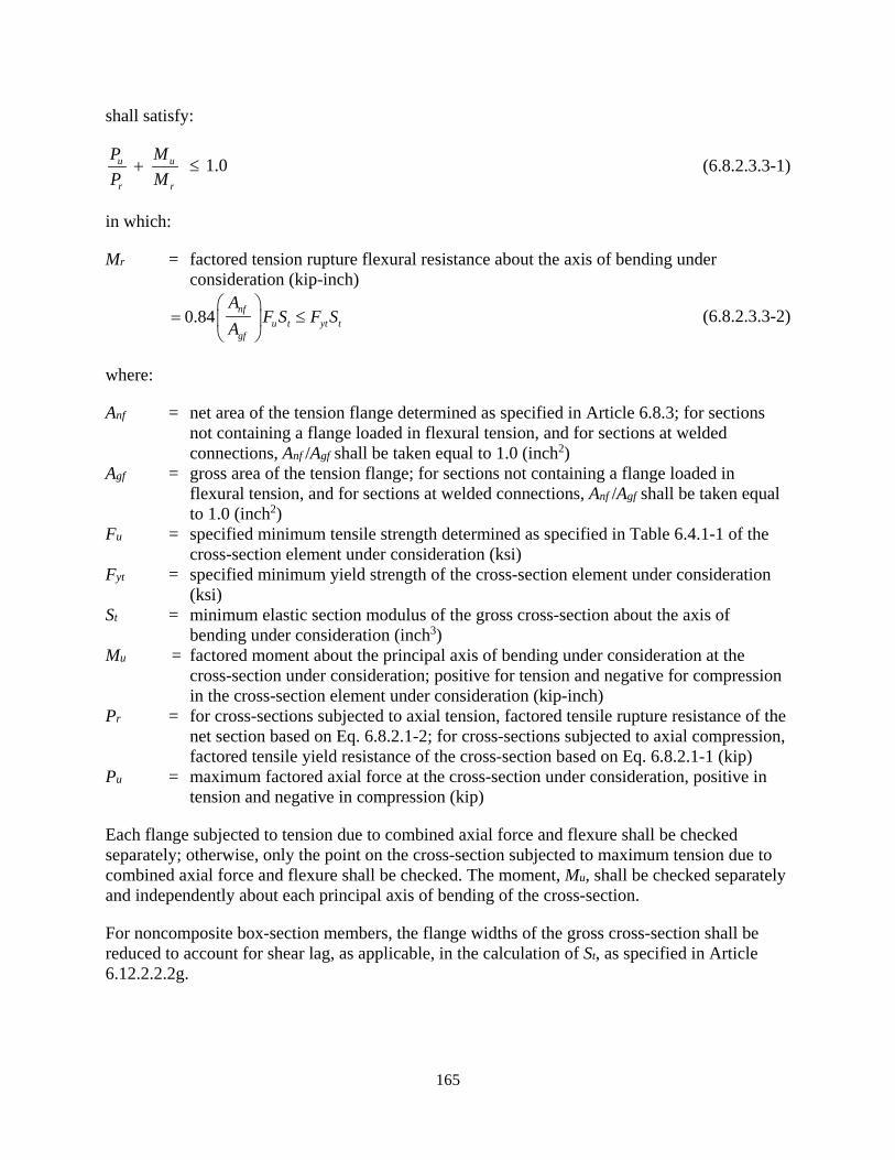
165
shall satisfy:
1.0u u
r r
P M P M
+ ≤ (6.8.2.3.3-1)
in which:
Mr = factored tension rupture flexural resistance about the axis of bending under consideration (kip-inch)
0.84 nfu t yt t
gf
AF S F S
A
= ≤
(6.8.2.3.3-2)
where:
Anf = net area of the tension flange determined as specified in Article 6.8.3; for sections not containing a flange loaded in flexural tension, and for sections at welded connections, Anf /Agf shall be taken equal to 1.0 (inch2)
Agf = gross area of the tension flange; for sections not containing a flange loaded in flexural tension, and for sections at welded connections, Anf /Agf shall be taken equal to 1.0 (inch2)
Fu = specified minimum tensile strength determined as specified in Table 6.4.1-1 of the cross-section element under consideration (ksi)
Fyt = specified minimum yield strength of the cross-section element under consideration (ksi)
St = minimum elastic section modulus of the gross cross-section about the axis of bending under consideration (inch3)
Mu = factored moment about the principal axis of bending under consideration at the cross-section under consideration; positive for tension and negative for compression in the cross-section element under consideration (kip-inch)
Pr = for cross-sections subjected to axial tension, factored tensile rupture resistance of the net section based on Eq. 6.8.2.1-2; for cross-sections subjected to axial compression, factored tensile yield resistance of the cross-section based on Eq. 6.8.2.1-1 (kip)
Pu = maximum factored axial force at the cross-section under consideration, positive in tension and negative in compression (kip)
Each flange subjected to tension due to combined axial force and flexure shall be checked separately; otherwise, only the point on the cross-section subjected to maximum tension due to combined axial force and flexure shall be checked. The moment, Mu, shall be checked separately and independently about each principal axis of bending of the cross-section.
For noncomposite box-section members, the flange widths of the gross cross-section shall be reduced to account for shear lag, as applicable, in the calculation of St, as specified in Article 6.12.2.2.2g.

166
3.3.2. Discussion
3.3.2.1. Combined Axial Compression, Flexure, Flexural and/or Torsional Shear, General (Article 6.9.2.2.1)
These provisions address the strength interaction for any combination of axial compression, uniaxial or biaxial flexure, and flexural and/or torsional shear, including combinations where one or more of the individual actions may be zero.
Interaction equations in members subjected to axial tension or compression in combination with other loading effects generally involve significant design simplification. Such equations involving exponents of 1.0 on the moment ratios are often conservative. More exact, nonlinear interaction curves are available and are discussed in Ziemian (2010). If these interaction equations are used, additional investigation of service limit state stresses may be necessary to avoid premature yielding.
Equations 6.9.2.2.1-1 and 6.9.2.2.1-2 are identical to Equations (H1-1a) and (H1-1b) of AISC (2016). They were selected for use in that Specification after being compared with a number of alternative formulations considering the results from refined inelastic analyses of 82 frame sidesway cases (Kanchanalai, 1977) involving rolled wide-flange section members. The strength envelope represented by these equations is similar to that shown for the axial tension and biaxial bending case in Fig. 6.8.2.3.1-1. Equations 6.9.2.2.1-1 and 6.9.2.2.1-2 provide an accurate to conservative approximation of the resistances under combined loading for members in which all the cross-section elements are compact. Such members are potentially able to develop significant distributed yielding within their cross-sections for small axial load and dominant flexural loading. As such, these types of members are able to develop a “knee” in the interaction curve between their flexural and axial compressive resistances. Members with other cross-section types generally have limited capability to develop such a “knee.”
For members where Equations 6.9.2.2.1-1 and 6.9.2.2.1-2 apply, the member ultimate resistances tend to involve extensive yielding in both tension and compression. For other member types, the member strength interaction is usually governed by additive compression buckling effects from axial compression and flexure, which are captured accurately to conservatively by the linear interaction Equation 6.9.2.2.1-3.
The strength interaction between flexure and axial tension or compression pertaining to tension flange rupture at a cross-section containing holes in the tension flange is addressed in Article 6.8.2.3.3. Article 6.8.2.3.3 provides a separate linear interaction equation focusing on the specific axial force combined with the specific moment causing the flexural tension in the flange at a given cross-section.
Pu, Mux, and Muy are concurrent factored axial and flexural forces determined from a structural analysis. The cross-sections exhibiting the maximum strength ratios generally are located at different positions along the member unbraced lengths. The beam-column strength interaction equations generally are not intended to be applied on a cross-section by cross-section basis along the member length, where typically only one of the strength ratios is maximum at a given cross-section, and the other ratios are at their non-maximum values. The cross-section by cross-section
167
approach to evaluating the strength interaction is appropriate only when: 1) all of the flexural strength ratios are cross-section based, e.g., when all Muy/Mry values are combined with Mux/Mrx values that are based on either flange local buckling, tension flange yielding, or the plateau strength in lateral-torsional buckling; and 2) the member is prismatic and the axial force Pu is constant along the length such that Pu/Pr is a constant value along the member length. The axial compressive strength ratio, Pu/Pr, and the lateral-torsional buckling strength ratio, Mux/Mrx, when Mrx is less than the plateau strength, depend on the overall length effects associated with the corresponding stability behavior. These strength ratios are not cross-section limit states checks. Hence, performing the member strength interaction checks on a cross-section by cross-section basis with the equations provided in this article is generally unconservative unless the above conditions are satisfied.
When Pu and/or Mux vary along the member length, the appropriate resistance terms in the strength ratios Pu /Pr and/or Mux /Mrx at a given cross-section should be the value of the axial load and/or the major-axis bending moment at that cross-section when the overall member resistance is reached within the corresponding buckling mode. These separate maximum strength ratios along the member unbraced length are then combined together in the member strength interaction checks. If Pu varies along the length relevant to the governing buckling mode, it is common to determine Pr based on the assumption of constant axial compression and to use the largest value of Pu along this length in determining Pu/Pr. More rigorously, the buckling resistance Pr can be determined as the internal axial force at a given cross-section at overall buckling of the member, considering the influence of the variation of the axial force along the member length, and the corresponding Pu at this cross-section can be divided by this Pr to obtain the governing strength ratio (White and Jeong, 2019). This more rigorous approach can also capture the influence of nonprismatic member geometry. This approach, along with the potentially beneficial influence of continuity effects and interaction buckling effects between the adjacent unbraced lengths, is discussed further in White and Jeong (2019).
In lieu of a more refined analysis, when considering the strength interaction at a given cross-section, the maximum Pu /Pr and the maximum Mux/Mrx values throughout the length relevant to the governing buckling modes should be used along with any cross-section based Mux/Mrx and Muy/Mry values. As a simplification, the Engineer can combine the maximum Pu/Pr, Mux/Mrx and Muy/Mry values throughout each of the smaller of the unbraced lengths x, y, z, i.e., the respective column buckling unbraced lengths, and/or Lb, i.e. the lateral-torsional buckling unbraced lengths, for a given location along the overall member length when evaluating the strength interaction equations. This accounts for the stability interactions between responses that are maximum at different cross-sections along the member length, while recognizing that, if say the largest Pu/Pr and/or Mux/Mrx values are located at positions far removed from each other, i.e., at positions farther apart than the smaller of x, y, z, and/or Lb, or from other cross-section based Mux/Mrx or Muy/Mry values being applied within the strength interaction checks, the combination of these maximum values in the strength interaction is conservative. The physical beam column experiences all of these effects together, and the only way of determining the true interaction between these effects is to employ some type of advanced analysis method that considers them together within a consistent mechanics-based context, as discussed briefly in Article C6.1.
168
In addition to properly considering the length effects associated with Pu /Pr and Mux /Mrx as discussed above, it is important to note that, due to the influence of the moment gradient factor, Cb, on the lateral-torsional buckling resistance, it is possible that a load combination with a major-axis bending moment smaller than the maximum Mux value for the relevant load combinations under consideration can have a larger strength ratio Mux /Mrx than the load combination corresponding to the largest Mux. When evaluating the various load combinations for a given design, the concurrent loadings for the load combination having the largest Mux/Mrx must be checked. The maximums of each of the strength ratios Pu/Pr, Mux/Mrx, and Muy /Mry from all relevant load combinations may be summed conservatively to evaluate the resistance under the combined loading.
Sxc and Sxt are defined in Equation 6.9.2.2.1-4 as equivalent values that account for the combined effects of the loads acting on different sections in composite members.
For I- and H-shaped sections, the nominal flexural resistance about an axis parallel to the web is determined according to the provisions of Article 6.12.2.2.1.
For tees and double angles subject to combined axial compression and flexure in which the axial and flexural stresses in the flange of the tee or the flange legs of the angles are additive in compression, e.g., when a tee is used as a bracing member and the connection of this member is made to the flange, a bulge in the interaction curve occurs. As a result, Equations 6.9.2.2.1-1 and 6.9.2.2.1-2 may significantly underestimate the resistance in such cases. Alternative approaches attempting to capture this bulge have proven to be generally inconclusive or incomplete. Therefore, it is recommended that Equations 6.9.2.2.1-1 and 6.9.2.2.1-2 be conservatively applied to these cases. Should significant additional resistance be required, the use of one or more of these alternative approaches, as described in White (2012), may be considered.
Tee stems and double-angle web legs in which the toe of the stem or leg is in flexural compression are not considered as compact elements; therefore, Equation 6.9.2.2.1-3 should be applied in cases where the toe of the tee stem or double-angle web legs are subject to flexural compression. Tee stems and double angle web legs in which the toe of the stem or leg is in flexural tension are considered as compact elements; thus, Equations 6.9.2.2.1-1 and 6.9.2.2.1-2 may be applied in this case.
When they are additive with the corresponding moments Mux and Muy, additional eccentric bending moments, Pu ecy and Pu ecx, respectively, may be included in Equations 6.9.2.2.1-1 through 6.9.2.2.1-3 in conjunction with the moments Mux and Muy for members having singly-symmetric or unsymmetric cross-sections containing longitudinally stiffened plate elements, or elements that are slender under uniform axial compression according to Article 6.9.4.2.2a for reasons discussed below, where:
ecx = eccentricity in the y-direction of the centroid of the effective cross-sectional area, Aeff, relative to the centroid of the gross cross-sectional area, Ag, causing additional moments that are additive with Muy (inch)
ecy = eccentricity in the y-direction of the centroid of the effective cross-sectional area, Aeff, relative to the centroid of the gross cross-sectional area, Ag, causing additional moments that are additive with Mux (inch)
169
These bending moments account conservatively for the eccentric bending caused by the loss of effectiveness of cross-section elements due to local buckling in members with these types of cross-sections. These eccentricity effects can have a measurable impact on the resistance of an ideally pin-ended member; however, they tend to be minor in members where the end rotations are restrained due to support conditions or continuity with other framing. AISI (2016) and AISC (2016) neglect these effects. The AISI (2012) Specification included this effect for axial compression. Eurocode 3 Part 1-1 (CEN, 2005) requires the consideration of this effect both for axial compression and for axial tension.
3.3.2.2. Interaction of Axial Compression and Flexure with Torsional and/or Flexural Shear (Article 6.9.2.2.2)
Equations 6.9.2.2.2-1 through 6.9.2.2.2-3 address the influence of torsional and/or flexural shear, as applicable, on the resistance of noncomposite rectangular box-section members and noncomposite circular tubes, including round HSS. In addition, they address the interaction between the flexural shear resistance and the axial resistance of I-section members. I-section members with thin webs, subjected to significant axial force, potentially have a measureable interaction between their flexural shear and axial load resistances. The interaction between torsional and/or flexural shear stresses in I-section member flanges with other member resistances is neglected in these provisions.
Equations 6.9.2.2.2-1 through 6.9.2.2.2-3 are based on an interaction between the shear resistance and the combined axial and flexural resistance of the member and its component plates in which the axial and flexural strength ratios are taken as linear terms, with an exponent of 1, and the torsional and/or flexural shear strength ratio is taken as a quadratic term with an exponent of 2. The interaction with the torsional and/or flexural shear is applied to the axial compressive and flexural resistance terms, rather than writing a separate term involving the torsional and/or flexural shear in the strength interaction equations.
The interaction assumed by Equations 6.9.2.2.2-1 through 6.9.2.2.2-3 gives an accurate to moderately conservative representation of the plastic strength interaction between normal and shear stresses obtained from the von Mises yield criterion, the inelastic buckling interaction in plates subjected to combined uniform axial compression and shear, and the elastic buckling interaction in plates subjected to combined bending within the plane of the plate and shear (Ziemian, 2010). The theoretical interaction curve between the normalized strength ratios is circular for each of these cases, which would result in the expressions within Equations 6.9.2.2.2-1 through 6.9.2.2.2-3 being taken to the ½, or square root, power. However, the plate elastic buckling interaction between uniform axial compression and shear is approximated more closely by an interaction equation involving a linear term for the axial compressive strength ratio and a quadratic term for the shear strength ratio, which results in the form given by Equations 6.9.2.2.2-1 through 6.9.2.2.2-3 (Ziemian, 2010). The largest difference between the overall strengths predicted by the circular interaction and the interaction using a linear term for the axial compressive strength ratio and a quadratic term for the shear strength ratio is 15 percent, corresponding to a shear strength ratio of 0.707. Also, the ultimate shear resistance in the theoretical elastic shear buckling range is larger than the theoretical elastic shear buckling resistance, due to postbuckling action. In these provisions, the interaction based on using a linear term for the axial compressive and flexural strength ratios is adopted to characterize the member
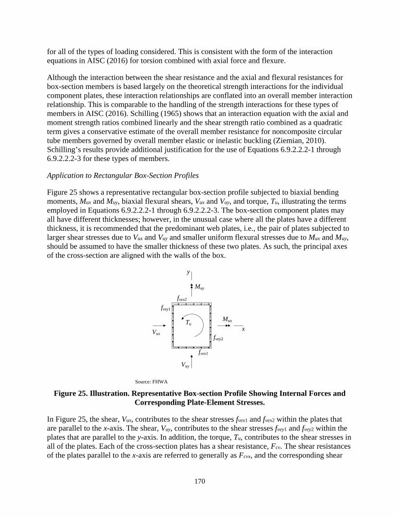
170
for all of the types of loading considered. This is consistent with the form of the interaction equations in AISC (2016) for torsion combined with axial force and flexure.
Although the interaction between the shear resistance and the axial and flexural resistances for box-section members is based largely on the theoretical strength interactions for the individual component plates, these interaction relationships are conflated into an overall member interaction relationship. This is comparable to the handling of the strength interactions for these types of members in AISC (2016). Schilling (1965) shows that an interaction equation with the axial and moment strength ratios combined linearly and the shear strength ratio combined as a quadratic term gives a conservative estimate of the overall member resistance for noncomposite circular tube members governed by overall member elastic or inelastic buckling (Ziemian, 2010). Schilling’s results provide additional justification for the use of Equations 6.9.2.2.2-1 through 6.9.2.2.2-3 for these types of members.
Application to Rectangular Box-Section Profiles
Figure 25 shows a representative rectangular box-section profile subjected to biaxial bending moments, Mux and Muy, biaxial flexural shears, Vux and Vuy, and torque, Tu, illustrating the terms employed in Equations 6.9.2.2.2-1 through 6.9.2.2.2-3. The box-section component plates may all have different thicknesses; however, in the unusual case where all the plates have a different thickness, it is recommended that the predominant web plates, i.e., the pair of plates subjected to larger shear stresses due to Vux and Vuy and smaller uniform flexural stresses due to Mux and Muy, should be assumed to have the smaller thickness of these two plates. As such, the principal axes of the cross-section are aligned with the walls of the box.
Source: FHWA
Figure 25. Illustration. Representative Box-section Profile Showing Internal Forces and Corresponding Plate-Element Stresses.
In Figure 25, the shear, Vux, contributes to the shear stresses fvex1 and fvex2 within the plates that are parallel to the x-axis. The shear, Vuy, contributes to the shear stresses fvey1 and fvey2 within the plates that are parallel to the y-axis. In addition, the torque, Tu, contributes to the shear stresses in all of the plates. Each of the cross-section plates has a shear resistance, Fcv. The shear resistances of the plates parallel to the x-axis are referred to generally as Fcvx, and the corresponding shear
x
y
Mux
Muy
Vux
Vuy
Tu
fvex1
fvex2
fvey1
fvey2
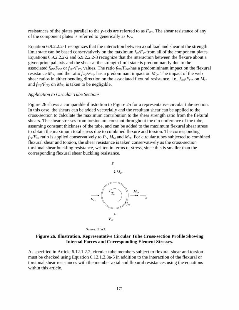
171
resistances of the plates parallel to the y-axis are referred to as Fcvy. The shear resistance of any of the component plates is referred to generically as Fcv.
Equation 6.9.2.2.2-1 recognizes that the interaction between axial load and shear at the strength limit state can be based conservatively on the maximum fve/Fcv from all of the component plates. Equations 6.9.2.2.2-2 and 6.9.2.2.2-3 recognize that the interaction between the flexure about a given principal axis and the shear at the strength limit state is predominantly due to the associated fvex/Fcvx or fvey/Fcvy values. The ratio fvex/Fcvx has a predomininant impact on the flexural resistance Mrx, and the ratio fvey/Fcvy has a predominant impact on Mry. The impact of the web shear ratios in either bending direction on the associated flexural resistance, i.e., fvex/Fcvx on Mry and fvey/Fcvy on Mrx, is taken to be negligible.
Application to Circular Tube Sections
Figure 26 shows a comparable illustration to Figure 25 for a representative circular tube section. In this case, the shears can be added vectorially and the resultant shear can be applied to the cross-section to calculate the maximum contribution to the shear strength ratio from the flexural shears. The shear stresses from torsion are constant throughout the circumference of the tube, assuming constant thickness of the tube, and can be added to the maximum flexural shear stress to obtain the maximum total stress due to combined flexure and torsion. The corresponding fve/Fcv ratio is applied conservatively to Pr, Mrx and Mry. For circular tubes subjected to combined flexural shear and torsion, the shear resistance is taken conservatively as the cross-section torsional shear buckling resistance, written in terms of stress, since this is smaller than the corresponding flexural shear buckling resistance.
Source: FHWA
Figure 26. Illustration. Representative Circular Tube Cross-section Profile Showing Internal Forces and Corresponding Element Stresses.
As specified in Article 6.12.1.2.2, circular tube members subject to flexural shear and torsion must be checked using Equation 6.12.1.2.3a-5 in addition to the interaction of the flexural or torsional shear resistances with the member axial and flexural resistances using the equations within this article.
x
y
Mux
Muy
Vux
Vuy
Tu
fve
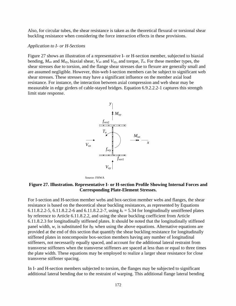
172
Also, for circular tubes, the shear resistance is taken as the theoretical flexural or torsional shear buckling resistance when considering the force interaction effects in these provisions.
Application to I- or H-Sections
Figure 27 shows an illustration of a representative I- or H-section member, subjected to biaxial bending, Mux and Muy, biaxial shear, Vux and Vuy, and torque, Tu. For these member types, the shear stresses due to torsion, and the flange shear stresses due to flexure are generally small and are assumed negligible. However, thin-web I-section members can be subject to significant web shear stresses. These stresses may have a significant influence on the member axial load resistance. For instance, the interaction between axial compression and web shear may be measurable in edge girders of cable-stayed bridges. Equation 6.9.2.2.2-1 captures this strength limit state response.
Source: FHWA
Figure 27. Illustration. Representative I- or H-section Profile Showing Internal Forces and Corresponding Plate-Element Stresses.
For I-section and H-section member webs and box-section member webs and flanges, the shear resistance is based on the theoretical shear buckling resistances, as represented by Equations 6.11.8.2.2-5, 6.11.8.2.2-6 and 6.11.8.2.2-7, using ks = 5.34 for longitudinally unstiffened plates by reference to Article 6.11.8.2.2, and using the shear buckling coefficient from Article 6.11.8.2.3 for longitudinally stiffened plates. It should be noted that the longitudinally stiffened panel width, w, is substituted for bfc when using the above equations. Alternative equations are provided at the end of this section that quantify the shear buckling resistance for longitudinally stiffened plates in noncomposite box-section members having any number of longitudinal stiffeners, not necessarily equally spaced, and account for the additional lateral restraint from transverse stiffeners when the transverse stiffeners are spaced at less than or equal to three times the plate width. These equations may be employed to realize a larger shear resistance for close transverse stiffener spacing.
In I- and H-section members subjected to torsion, the flanges may be subjected to significant additional lateral bending due to the restraint of warping. This additional flange lateral bending
x
y
Mux
Muy
Vux
Vuy
Tu
fvex1
fvex2
fvey
173
may be considered by calculating Muy/Mry considering each of the individual flanges as a separate component, and then combining the larger of these Muy/Mry values with the other strength ratios in the appropriate strength interaction equations. Alternatively, for I-section members subjected to major- and minor-axis bending plus torsion the one-third rule provisions of Article 6.10 may be employed to assess these combined effects
The interaction of flange flexural shear stresses with the axial and flexural resistances of the member is assumed to be negligible for I-section and H-section members designed by these Specifications. The weak-axis shear resistance of these types of members is checked using Article 6.12.1.2.3a.
General Application Considerations
The interaction between shear postbuckling and the other member resistances is considered to not be sufficiently established, for general cases, to permit the consideration of interaction of shear postbuckling resistance with the other resistances.
When the maximum ratio of the factored torsional shear stress to the corresponding cross-section element factored shear resistance, fve /φTFcv is less than 0.2, the reduction in the member and plate axial compressive and flexural resistances due to the torsional shear stress is less than 4 percent, and is therefore neglected. Furthermore, when Pu /Pr is less than or equal to 0.05, the influence of this term on the unity check in Equations 6.9.2.2.1-1 through 6.9.2.2.1-3 is always less than or equal to 0.05. As such, the effect of the axial force on the design of the member may be neglected, as indicated in Articles C6.10.6.1 and C6.11.6.2.1.
In addition, when Pu /Pr is less than or equal to 0.05, the influence of flexural shear stresses may be neglected when applying Equations 6.9.2.2.2-1 through 6.9.2.2.2-3. This recognizes the well-established observation that moment-shear strength interaction is small and may be neglected in I- and box-girder flexural members (White et al., 2008; Johansson et al., 2007; AISC, 2016). When evaluating the factored shear resistance of a member subject to torsion, additive shear stresses from flexure and from torsion are to be considered. However, these additive shear stresses need not be considered in evaluating the strength interaction in Article 6.9.2.2.2 when the exclusion clauses permitting the torsional shear stress and/or the flexural shear stress to be neglected are satisfied.
Flexural shear stresses in flanges need not be considered in Equations 6.9.2.2.2-1 through 6.9.2.2.2-3. The flange shear stresses due to flexure, which are tangent to the wall of the flange plate, are maximum at the connection to the webs, zero at a location within the middle of the plate, and the net shear force in the flanges is zero. The flexural shear stresses in flange elements of I-section members subjected to major-axis bending also need not be considered in Equations 6.9.2.2.2-1 through 6.9.2.2.2-3 for similar reasons. That is, flexural shear stresses only need to be considered in the member web or webs.
It should be noted that in box-section members, the flanges associated with one direction of bending are the webs associated with the other direction of bending, and vice versa. Therefore, for members subjected to biaxial bending, the same elements must be designed as a web element for bending in one direction, and as a flange element for bending in the other direction.
174
When addressing the additional interaction with torsion and/or flexural shear using the equations specified in Article 6.9.2.2.1, the maximum torsional shear and/or flexural shear ratios, fve/φTFcv, fvex/φTFcvx, and fvey/φTFcvy, which produce the corresponding minimum ∆, ∆x and ∆y values, are to be combined with the other strength ratios determined according to Article 6.9.2.2.1 within each of the smallest unbraced lengths along the overall member length. Based on the above considerations, the fve, fvex and/or fvey values in Article 6.9.2.2.1 may be taken as the combined torsional and flexural shear stresses, the torsional shear alone, the flexural shear alone, or zero.
Estimation of Torsional Shear Stresses
In lieu of a refined analysis, the factored torsional shear stresses in the cross-section element under consideration for use in Equations 6.9.2.2.2-1 through 6.9.2.2.2-3 may be calculated as follows:
• For noncomposite circular tubes, including round HSS:
= 22uTr tπ
(120)
• For web and flange elements of noncomposite rectangular box-section members, including square and rectangular HSS:
=2
u
o
TA t
(121)
where:
Ao = enclosed area within the box section (inch2) Tu = factored torque (kip-inch) r = radius to the mid-thickness of the tube (inch) t = element thickness (inch); for HSS, the provisions of Article 6.12.1.2.4 shall apply.
Refined Shear Buckling Coefficients for Longitudinally Stiffened Plates
In lieu of the use of the shear buckling coefficient from Equation 6.11.8.2.3-3 with Equations 6.11.8.2.2-5, 6.11.8.2.2-6 and 6.11.8.2.2-7 to quantify the shear buckling resistance of longitudinally stiffened plates, the following shear buckling coefficients provide a more accurate representation of the shear buckling resistance:
• For longitudinally stiffened flange elements with one or two longitudinal stiffeners and with 1 ≤ a/bsp ≤ 3:
( ) ( )
23
232 3
6.3 0.546 45.344.1 3.19 //
smin
sp sp sminssp
sp spsp
n Iwb t n Ik b a wb ta b
+ = ≤ + + +
(122)
175
• For longitudinally stiffened flange elements with more than two longitudinal stiffeners and 1 ≤ a/bsp ≤ 3:
( ) ( )
( )
3/4 2
32 2
2
3 3 2
4 20.75.34/ /
45.34 3.01 5.34/
smins
sp sp spsp sp
smin
spsp sp
n I wk b t ba b a b
wn Ibb t a w
+ +=
+≥ ≤ +
(123)
• For longitudinally stiffened flange elements with any number of longitudinal stiffeners and a/bsp > 3:
2
3 35.34 3.01 5.34smins
spsp sp
wn Ik bb t
+= ≤
(124)
where:
a = longitudinal spacing between locations of transverse stiffeners satisfying the provisions of Article 6.9.4.2.2f, or diaphragms, that provide transverse lateral restraint to the plate under consideration (inch)
bsp = total inside width between the plate elements providing lateral restraint to the longitudinal edges of the longitudinally stiffened plate element under consideration (inch)
n = number of longitudinal stiffeners attached to the longitudinally stiffened plate under consideration
tsp = thickness of the longitudinally stiffened plate element under consideration (inch) w = width of the panel under consideration between individual longitudinal stiffeners, or
between a longitudinal stiffener and the laterally-restrained edge of the plate (inch) Ismin = smallest moment of inertia of the individual stiffener struts composed of the stiffener
plus the tributary width of the longitudinally stiffened plate element under consideration, taken about an axis parallel to the face of the longitudinally stiffened plate element and passing through the centroid of the gross combined area of the longitudinal stiffener and its tributary plate width (inch4)
Equations 122 through 124 quantify the shear buckling resistance of longitudinally stiffened flange elements in noncomposite box-section members having any number of longitudinal stiffeners, not necessarily equally spaced. In addition, these equations address the influence of transverse stiffeners. The comparable Equation 6.11.8.2.3-3 is based on the assumption of equal spacing of the longitudinal stiffeners and a theoretically infinitely long plate without transverse stiffening.
Equations 122 and 123 are adapted from similar equations defined in Eurocode 3 Part 1-5 (CEN, 2006b). Equation 122 is equivalent to a corresponding equation given in Annex A.3 of Eurocode 3 Part 1-5, except that: (1) n times the minimum stiffener moment of inertia, Ismin, is employed, rather than summing the longitudinal stiffener moments of inertia, to accommodate cases with
176
different size longitudinal stiffeners, and (2) the coefficients on the terms involving nIsmin are modified to correspond to the theoretical shear buckling resistance. The upper limit in Equation 122 is the shear buckling coefficient of a plate panel having rigid longitudinal and transverse edge restraints. Equation 123 and its lower limit are equivalent to a corresponding equation in Annex A.3 of Eurocode 3 Part 1-5 (CEN, 2006b), except with the same modifications as discussed above for Equation 122. The upper limit in Equation 123 is again the shear buckling coefficient of a plate panel having rigid longitudinal and transverse edge restraints. Equation 124 is a lower-bound constant value from Equation 123 for the case where a/bsp > 3. For plates with equally-spaced equal-size longitudinal stiffeners, this equation reduces to Equation 6.11.8.2.3-3 except with a coefficient of 3.01 in the second term of the numerator rather than 2.84.
For cases where a/bsp < 1, the following modifications should be made to Equations 122 and 123, as applicable:
• The first two terms in Equation 123 must be changed to
( )25.344/ spa b
+ (125)
• In addition, for cases with a/w < 1, the upper limit in both Equations 122 and 123 must be changed to
( )25.344/a w
+ (126)
With these changes, Equations 122 and 123 are applicable to cases with a/bsp < 1.
3.3.2.3. Combined Axial Tension, and Flexure, and Fleuxural and/or Torsional Shear, General (Article 6.8.2.3.1)
These provisions address the strength interaction for any combination of axial tension, uniaxial or biaxial flexure, and flexural and/or torsional shear, including combinations where one or more of the individual actions may be zero.
Equations 6.8.2.3.1-1 and 6.8.2.3.1-2 represent the stability and overall strength interaction effects for uniaxial or biaxial bending combined with axial tension and general yielding under axial tension and flexure. Figure 28 shows the shape of this strength envelope.
When Mrx is influenced by lateral-torsional buckling, Mux/Mrx depends on the overall length effects associated with the lateral-torsional buckling strength limit state. Therefore, in this case, Equations 6.8.2.3.1-1 and 6.8.2.3.1-2 are not cross-section resistance checks. Hence, the largest value of Mux/Mrx associated with the unbraced length relevant to the lateral-torsional buckling resistance should be considered along with the other cross-section based values of Muy/Mry and Pu/Pry. That is, when Mrx is governed by lateral-torsional buckling, there is one Mux/Mrx value for a given unbraced length that may be combined with the individual cross-section based Muy/Mry and Pu/Pry values. Furthermore, one should recognize that the largest value of Mux/Mrx does not necessarily occur for the load combination that gives the largest value of Mux, as discussed in Section 3.3.2.1.

177
Source: FHWA
Figure 28. Illustration. Interaction Between Axial Tension and Biaxial Bending Corresponding to Equations 6.8.2.3.1-1 and 6.8.2.3.1-2.
Considering the above attributes, the largest Mux/Mrx associated with the unbraced length relevant to the lateral-torsional buckling resistance may be combined conservatively with the largest Muy/Mry and Pu/Pry values along this length in evaluating Equations 6.8.2.3.1-1 and 6.8.2.3.1-2.
When Mrx is governed by a limit state other than lateral-torsional buckling, all the resistance terms in Equations 6.8.2.3.1-1 and 6.8.2.3.1-2 are cross-section based, and therefore, these equations may be evaluated on a cross-section by cross-section basis along the member length. The Engineer is referred to Section 3.3.2.2 for a more detailed discussion of when cross-section by cross-section based evaluation of strength interaction equations is and is not appropriate.
Equations 6.8.2.3.1-3 and 6.8.2.3.1-4 define the strength interaction curve shown in Figure 29, which conservatively recognizes that axial tension tends to have a negligible to beneficial impact on the flexural resistances associated with compression buckling; therefore, the unity check value from the compression-buckling based strength interaction equation, Equation 6.8.2.3.1-4, need not consider the influence of the axial tension. Equation 6.8.2.3.1-4 limits the flexural resistances to a linear interaction between Mrxc and Mryc. The flexural resistance is not reduced below that associated with Equation 6.8.2.3.1-4 until a linear interaction between the yield load in tension, Pry, and the corresponding plastic moments, Mrxpe or Mrype, is reached according to Equation 6.8.2.3.1-3. For doubly symmetric I-section members, Equations 6.8.2.3.1-3 and
1.02
uyu ux
ry rx ry
MP M
P M M
+ + ≤
Eq. 6.8.2.3.1-1
u
ry
P
P
8 1.09
uyu ux
ry rx ry
MP M
P M M
+ + ≤
ux
rx
MM
uy
ry
MM
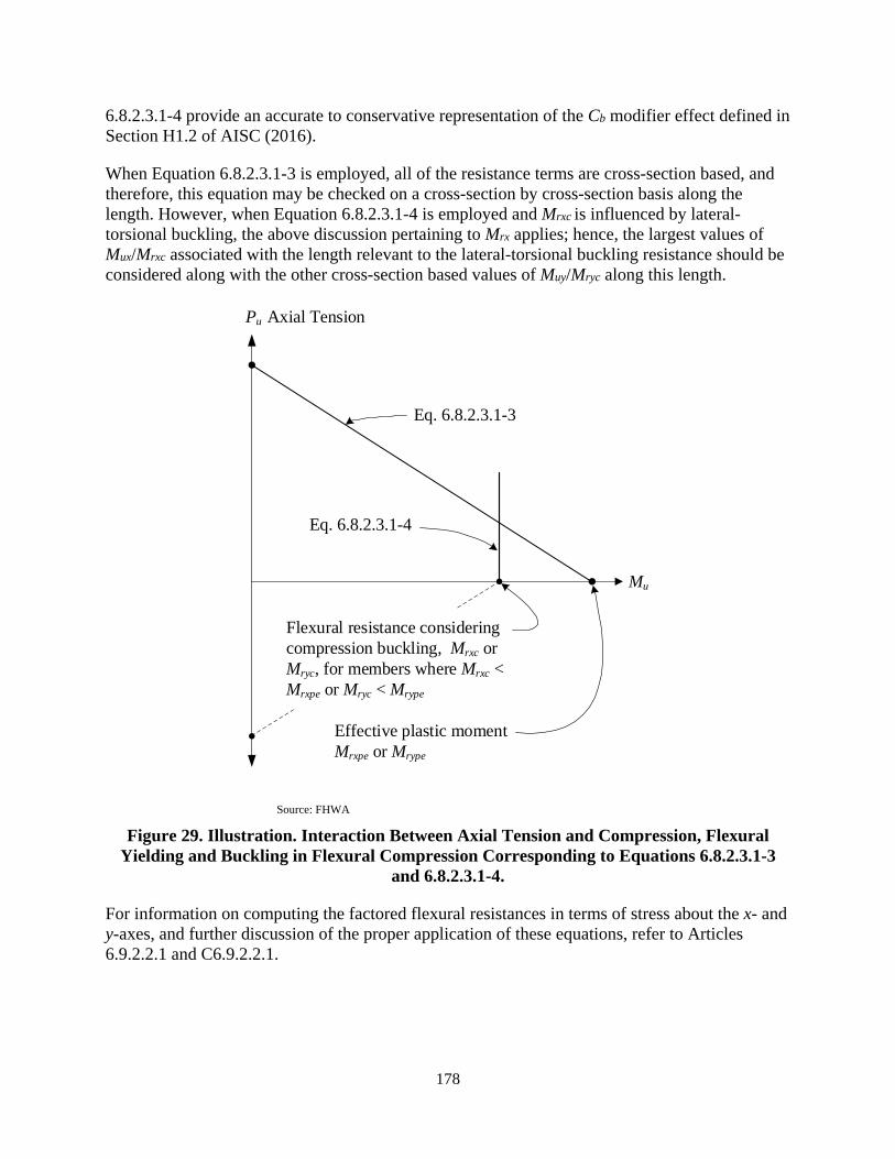
178
6.8.2.3.1-4 provide an accurate to conservative representation of the Cb modifier effect defined in Section H1.2 of AISC (2016).
When Equation 6.8.2.3.1-3 is employed, all of the resistance terms are cross-section based, and therefore, this equation may be checked on a cross-section by cross-section basis along the length. However, when Equation 6.8.2.3.1-4 is employed and Mrxc is influenced by lateral-torsional buckling, the above discussion pertaining to Mrx applies; hence, the largest values of Mux/Mrxc associated with the length relevant to the lateral-torsional buckling resistance should be considered along with the other cross-section based values of Muy/Mryc along this length.
Source: FHWA
Figure 29. Illustration. Interaction Between Axial Tension and Compression, Flexural Yielding and Buckling in Flexural Compression Corresponding to Equations 6.8.2.3.1-3
and 6.8.2.3.1-4.
For information on computing the factored flexural resistances in terms of stress about the x- and y-axes, and further discussion of the proper application of these equations, refer to Articles 6.9.2.2.1 and C6.9.2.2.1.
Flexural resistance considering compression buckling, Mrxc or Mryc, for members where Mrxc < Mrxpe or Mryc < Mrype
Eq. 6.8.2.3.1-4
Effective plastic moment Mrxpe or Mrype
Mu
Eq. 6.8.2.3.1-3
Pu Axial Tension
179
3.3.2.4. Interaction of Axial Tension and Flexure with Torsional and/or Flexural Shear (Article 6.8.2.3.2)
The factored torsional shear stresses in the cross-section element under consideration for use in the computation of ∆, ∆x, and ∆y may be computed using the equations given in Section 3.3.2.2 in lieu of a refined analysis.
3.3.2.5. Tension Rupture Under Axial Tension or Compression Combined with Flexure (Article 6.8.2.3.3)
Equation 6.8.2.3.3-1 addresses the strength interaction between flexure and axial tension or compression pertaining to tension rupture at the locations listed. This equation focuses on the specific axial force, tension or compression, combined with the specific moment at the cross-section under consideration. The axial strength ratio term is negative in Equation 6.8.2.3.3-1, causing a beneficial subtractive effect, when the cross-section having the bolt holes is subjected to axial compression. The axial strength ratio term is positive, causing an additive effect, when the cross-section is subjected to axial tension. This article is a generalization of Section H4 of AISC (2016), including the handling of tension flanges with holes in flexural members as specified in Article 6.10.1.8. The variable St is taken conservatively as the minimum elastic section modulus as in AISC (2016).
Angle members and light structural tee members loaded eccentrically in axial tension are to be designed only for axial tension; the moment effects due to connection eccentricities are addressed in the calculation of the shear lag reduction factor, U, in Article 6.8.2.2.
3.4. PLATE BUCKLING UNDER SERVICE AND CONSTRUCTION LOADS
3.4.1. Specification Provisions (Article 6.9.4.5)
6.9.4.5— Plate Buckling under Service, Fatigue and Construction Loads
The provisions contained herein shall not apply at the service limit state or during construction for webs of:
• Composite or noncomposite I-section members subject to flexure only,
• Composite box-section members subject to flexure only, and
• Noncomposite box-section members subject to flexure only, containing longitudinally unstiffened webs or webs with only one longitudinal stiffener.
Such members shall be checked for web bend buckling at these limit states according to the applicable provisions of Articles 6.10 and 6.11, respectively, using the appropriate web bend buckling resistance, Fcrw, specified in Article 6.10.1.9.
The provisions contained herein also shall not apply for plate elements supported only along one longitudinal edge and for walls of circular tubes.

180
All other
• Slender plate elements as defined in Article 6.9.4.2.2a, or
• Slender longitudinally stiffened plate panels as defined in Appendix E6.1.2
subjected to longitudinal compressive stress at one or both edges shall satisfy the following at the service limit state and for constructibility:
2
0.9c y
Ekf F≤ ≤λ
(6.9.4.5-1)
in which:
fc = maximum longitudinal compressive stress (ksi) acting on the gross cross-section in the plate element or longitudinally stiffened plate panel under consideration due to:
• The Service II loads;
• The factored load for constructibility as specified in Article 3.4.2.1.
For noncomposite box-section members, the flange widths of the gross cross-section shall be reduced to account for shear lag, as applicable, in the calculation of the stresses due to flexure, as specified in Article 6.12.2.2.2g.
k = plate-buckling coefficient considering any gradient in the longitudinal stress calculated as follows:
• If 1.0 ≥ 1
2
ff
≥ 0.0, then:
1
2
8.2
1.05k f
f
=+
(6.9.4.5-2)
• If 0.0 > 1
2
ff
≥ -1.0, then:
211
22
7.81 6.29 9.78ffkff
= − +
(6.9.4.5-3)
• If -1.0 > 1
2
ff
≥ -3.0, then:
21
2
15.98f
kf
−=
(6.9.4.5-4)
181
where:
λ = slenderness, bf/tf, w/tf, or D/tw, of the slender flange or web plate element or longitudinally stiffened plate panel under consideration, as applicable
bf = total inside width between the plate elements providing lateral restraint to the longitudinal edges of the flange plate element under consideration (inch)
D = total inside width between the plate elements providing lateral restraint to the longitudinal edges of the web plate element under consideration (inch)
f1 = smaller longitudinal stress at the longitudinal edges of the plate element or longitudinally stiffened plate panel at the cross-section under consideration, taken as positive in compression and negative in tension (ksi)
f2 = larger longitudinal compressive stress at the longitudinal edges of the plate element or longitudinally stiffened plate panel at the cross-section under consideration, taken as positive (ksi)
Fy = specified minimum yield strength of the plate element or longitudinally stiffened plate panel under consideration (ksi)
tf = thickness of the flange plate element or longitudinally stiffened flange plate panel under consideration (inch)
tw = thickness of the web plate element under consideration (inch) w = width of the plate between the centerlines of the individual longitudinal stiffeners or
between the centerline of the longitudinal stiffener and the inside of the laterally-restrained longitudinal edge of the longitudinally stiffened plate under consideration, as applicable (inch)
3.4.2. Discussion, Theoretical Elastic Plate Buckling Under General Compression and Flexure (Article 6.9.4.5)
The checks specified in Article 6.9.4.5 are not required at the service limit state and for constructibility for plate elements supported only along one longitudinal edge, webs of I-section and box-section members specified in this article that are subject to flexure only, or for the walls of circular tubes. The slenderness or plate buckling response of these types of elements is typically limited by other design provisions, which may be less restrictive in some cases, and/or the postbuckling response is not considered to be of any negative consequence.
Since significant post-buckling resistance is often assumed at the strength limit state in computing the nominal flexural and axial compressive resistance of members with cross-sections containing slender plate elements supported along two longitudinal edges and/or longitudinally stiffened plates supported along their two longitudinal edges and containing slender plate panels, such members must satisfy the provisions of this article to ensure that theoretical local buckling of those plate elements or panels does not occur at the service limit state and for constructibility. Equation 6.9.4.5-1 is used to check for theoretical local buckling at these limit states under the net combined normal stresses acting on each of these types of plate elements or panels subjected to compressive stress.
The influence of combined normal and shear stresses on theoretical plate buckling at the service limit state and for constructibility is not considered in these Specifications. Satisfaction of specified requirements to separately prevent theoretical buckling under normal stresses and
182
under shear stresses is considered sufficient as an approximate technique to control plate bending strains and transverse displacements. In experimental tests, noticeable plate bending deformations and associated transverse displacements can occur from the onset of load application due to initial plate out-of-flatness. Because of stable plate postbuckling behavior, there is no significant change in the rate of increase of the transverse displacements as the theoretical plate buckling stress is exceeded. Due to unavoidable geometric imperfections, the plate buckling behavior is a load-deflection problem rather than a bifurcation problem. Satisfaction of the specified requirements to prevent theoretical buckling helps limit the magnitude of the corresponding transverse displacements.
Plate local buckling is not checked at the fatigue limit state in these provisions because the plate buckling check under the Service II loads will tend to control over a similar check under the unfactored permanent load plus the Fatigue I load combination.
Any box-section member plate element subjected to stress due to bending about a principal axis of the box parallel to the plate is considered as a flange plate element for bending about that axis. Any member plate element subjected to flexural shear orthogonal to the axis of bending, and/or nominally linearly varying normal stresses due to bending about an axis normal to the face of the plate, is considered as a web plate element. It should be noted that in box-section members, the flange plate elements associated with one direction of bending are the web plate elements associated with the other direction of bending, and vice versa. Therefore, for members subjected to biaxial bending, the same elements are designed as a web plate element for bending in one direction, and as a flange plate element for bending in the other direction.
The plate-buckling coefficient, k, given by Equations 6.9.4.5-2 through 6.9.4.5-4 is from CEN (2006b). These equations address general loading conditions from any combination of axial compression and bending within the plane of the plates for the evaluation of longitudinally unstiffened plates and longitudinally stiffened plate panels. They are based on the idealization of general plates and plate panels as having simply supported boundary edge conditions. The ratio f1/f2 is less than or equal to 1.0 in all cases, since f1 is the smaller edge stress. The stress f1 may be a smaller compressive value compared to f2, or it may be a tensile stress, in which case f1 is taken as a negative value. The ratio f1/f2 is positive when both f1 and f2 are in compression, and it is negative when f1 is in tension. For unusual cases where the ratio of f1/f2 is smaller than -3, buckling of the plate is unlikely. In this case, it is conservative to use k equal to 96.
A plate-buckling coefficient of k = 4.0 may be employed conservatively in Equation 6.9.4.5-1 as an initial design check. Web plate elements in noncomposite box-section members subjected predominantly to flexure often may require the larger k values from Equations 6.9.4.5-2 through 6.9.4.5-4 to satisfy the requirement of Equation 6.9.4.5-1.
Figure 20 provides further information on the definition of the variable, w, for longitudinally stiffened plates.
3.5. SOLID WEB ARCHES
3.5.1. Specification Provisions (Article 6.14.4)
6.14.4—Solid Web Arches
183
6.14.4.1−General
These provisions are applicable for arch ribs satisfying the following limits:
• For flange extensions of box sections, flanges of I-sections, and/or web longitudinal stiffeners:
0.12b Rt b≤ (6.14.4.1-1)
• For flanges of box sections:
0.47fi
fi
b Rt b≤ (6.14.4.1-2)
where:
R = radius of curvature of the arch rib at the mid-depth of the web for the section under consideration (inch)
bfi = clear width of the flange under consideration between the insides of the webs (inch) b = unsupported width of the cross-section plate component under consideration (inch)
taken as follows:
• For flange extensions of box sections: = clear projecting width of the flange under consideration measured from the outside
surface of the web (inch)
• For I-section flanges: = one-half the total width of the flange (inch)
• For web longitudinal stiffeners: = projecting width of the longitudinal stiffener relative to the surface of the web (inch)
t = thickness of the cross-section plate component under consideration (inch)
Where longitudinal stiffeners are employed on flanges of arch ribs, transfer of the radial load from the axial force in the longitudinal stiffeners acting through the vertical curve to the webs of the arch rib shall be considered.
Web longitudinal stiffeners on arch ribs should be flat plates and shall satisfy the requirements of Article E6.1.3.
If the requirements of Article 6.10.11.3 are not satisfied for longitudinally stiffened webs, the member flexural resistance should be calculated neglecting the longitudinal stiffeners when determining Rb in Article 6.10.1.10.2.
184
6.14.4.2—Web Slenderness
The web or webs of arch ribs shall satisfy the following in addition to the applicable web slenderness requirements from Articles 6.10.2.1 or 6.12.2.2.2b:
( )
0.40
0.181/
fs yf
w
yf
Ed Ft E
R D F
≤+
(6.14.4.2-1)
where:
dfs = web depth for ribs with webs that are longitudinally unstiffened; maximum distance between the compression or the tension flange and the adjacent longitudinal stiffener for ribs with webs that are longitudinally stiffened (inch)
D = web depth (inch) Fyf = specified minimum yield strength of the flange under consideration (ksi) R = radius of curvature of the arch rib at the mid-depth of the web for the section under
consideration (inch) tw = web thickness (inch)
6.14.4.3—Moment Amplification
For moment amplification, the provisions specified in Article 4.5.3.2.2c shall be satisfied.
6.14.4.4—Nominal Compressive Resistance
The nominal compressive resistance of noncomposite arch ribs shall be determined using the provisions specified in Article 6.9.4.1.
In lieu of a more rigorous buckling analysis, the in-plane elastic critical flexural buckling resistance of arch ribs shall be calculated using the K values specified in Table 4.5.3.2.2c-1.
In lieu of a more rigorous buckling analysis, the out-of-plane elastic critical flexural buckling resistance shall be calculated as specified in Article 4.6.2.5. The characteristics of the framing in the out-of-plane direction shall be considered in determining the out-of-plane elastic critical buckling resistance using either approach.
6.14.4.5—Nominal Flexural Resistance
The nominal flexural resistance of noncomposite arch ribs shall be determined using the provisions of Article 6.10 or 6.12, as applicable. The developed unbraced length along the vertical curve between the brace points, Ldb, shall be used for the unbraced length Lb. The reduction of the lateral torsional buckling resistance due to the vertical curvature of the arch rib shall be considered. For box-section arch ribs with Ldb/R greater than 0.20, subjected to bending moments causing compression on the flange farthest from the center of curvature of the rib, where R is the minimum radius of curvature of the arch rib measured to the mid-depth of the
185
web, the moment gradient modifier, Cb, may be multiplied by 0.90 in lieu of a more refined buckling analysis.
6.14.4.6— Combined Axial Compression or Tension with Flexure and Torsion
The interaction between axial compression or tension resistances, flexural resistances, and flexural shear and/or torsion shall be considered as specified in Articles 6.9.2.2 and 6.8.2.3, as applicable.
3.5.2. Discussion
3.5.2.1. General Requirements (Article 6.14.4.1)
The restrictions on arch rib proportions specified in this article eliminate the need for the consideration of any reduction on the strength of arch rib plate elements due to the influence of the vertical curvature of the arch rib. The geometry of most arch ribs is such that no reduction is required for the influence of the vertical curvature on the strength of the flange plates and the web stiffener plates. Equations are provided below, giving a reduced effective yield strength of the arch rib component plates to extend the application of Article 6.14.4 to a broader range of geometries. Equations 6.14.4.1-1 and 6.14.4.1-2 are based on these equations.
The use of longitudinal stiffeners on arch rib flanges is discouraged. The action of the axial force in flange longitudinal stiffeners acting through the vertical curvature of the arch rib induces significant radial forces from the longitudinal stiffeners, which must be transferred to the web or webs of the arch rib. In addition, for other than potentially free-standing arches, it is unlikely that the flanges of arch ribs would need to be wide enough to benefit from longitudinal stiffening of the flanges.
For unusual cases where the flanges in box-section arch ribs have longitudinal stiffeners, the radial load from the axial force in the longitudinal stiffeners acting through the vertical curve must be transferred from the longitudinal stiffeners to the webs of the arch rib, or longitudinally to transverse stiffening elements and then to the webs of the arch rib. For flanges with only one longitudinal stiffener and a wide spacing of transverse stiffeners and diaphragms, the likely predominant load path for this force transfer is via transverse bending of the flange plate. In this case, the behavior is similar to the out-of-plane loading on the flanges themselves, due to the longitudinal forces in the flange plates acting through the vertical curve, i.e., the actions considered in the development of Equations 6.14.4.1-1 and 6.14.4.1-2. In the unlikely case of a wider arch rib flange with multiple longitudinal stiffeners, it is unlikely that the flange plate would have sufficient transverse stiffness and strength to develop the radial forces from the longitudinal stiffeners back to the webs of the arch rib. In this case, the likely practical load path is for the longitudinal stiffeners to transfer the subject radial forces to the transverse stiffeners and diaphragms, which then transfer these forces to the webs. Upon considering this behavior, the Engineer can determine a reduction factor on the capacity of the longitudinal stiffener struts, Pns, accounting for the effect of the transverse bending of the stiffener struts in transmitting the radial loads to the transverse stiffeners and diaphragms. Furthermore, the transverse stiffeners must be designed for this component of loading.
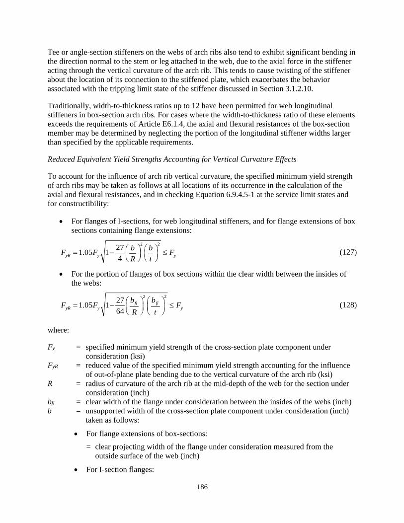
186
Tee or angle-section stiffeners on the webs of arch ribs also tend to exhibit significant bending in the direction normal to the stem or leg attached to the web, due to the axial force in the stiffener acting through the vertical curvature of the arch rib. This tends to cause twisting of the stiffener about the location of its connection to the stiffened plate, which exacerbates the behavior associated with the tripping limit state of the stiffener discussed in Section 3.1.2.10.
Traditionally, width-to-thickness ratios up to 12 have been permitted for web longitudinal stiffeners in box-section arch ribs. For cases where the width-to-thickness ratio of these elements exceeds the requirements of Article E6.1.4, the axial and flexural resistances of the box-section member may be determined by neglecting the portion of the longitudinal stiffener widths larger than specified by the applicable requirements.
Reduced Equivalent Yield Strengths Accounting for Vertical Curvature Effects
To account for the influence of arch rib vertical curvature, the specified minimum yield strength of arch ribs may be taken as follows at all locations of its occurrence in the calculation of the axial and flexural resistances, and in checking Equation 6.9.4.5-1 at the service limit states and for constructibility:
• For flanges of I-sections, for web longitudinal stiffeners, and for flange extensions of box sections containing flange extensions:
22271.05 14yR y y
bbF F FtR
= − ≤
(127)
• For the portion of flanges of box sections within the clear width between the insides of the webs:
22271.05 164
fifiyR y y
bbF F FtR
= − ≤
(128)
where:
Fy = specified minimum yield strength of the cross-section plate component under consideration (ksi)
FyR = reduced value of the specified minimum yield strength accounting for the influence of out-of-plane plate bending due to the vertical curvature of the arch rib (ksi)
R = radius of curvature of the arch rib at the mid-depth of the web for the section under consideration (inch)
bfi = clear width of the flange under consideration between the insides of the webs (inch) b = unsupported width of the cross-section plate component under consideration (inch)
taken as follows:
• For flange extensions of box-sections: = clear projecting width of the flange under consideration measured from the
outside surface of the web (inch)
• For I-section flanges:
187
= one-half the total width of the flange (inch)
• For web longitudinal stiffeners: = projecting width of the longitudinal stiffener relative to the surface of the web
(inch) t = thickness of the cross-section plate component under consideration (inch)
The smallest value of FyR determined from the corresponding flange elements is employed for the specified minimum yield strength of each flange of the cross-section in the calculation of member axial and flexural resistances. For longitudinally stiffened webs, the smallest value of FyR determined from the corresponding web longitudinal stiffeners is employed for the specified minimum yield strength of each web in the calculation of the member axial and flexural resistances.
Equation 6.14.4.1-1 is obtained by setting FyR equal to Fy in Equation 127 and solving for b/t, and Equation 6.14.4.1-2 is obtained by setting FyR equal to Fy in Equation 128 and solving for bfi/t.
Equations 127 and 128 reduce the specified minimum yield strength employed for the calculation of the axial and flexural resistances of arch ribs to account for the influence of transverse plate bending of the flange and web longitudinal stiffener plates due to the axial force in these components acting through the vertical curvature of the arch rib.
For most practical cases the above equations do not require any reduction relative to the specified minimum yield strengths. For a width-to-thickness ratio of 40, considering the clear inside width of a flange between the webs of a box-section, Equation 128 gives a value of FyR
smaller than Fy when b/R becomes larger than approximately 0.012, which is larger than the b/R value for most arch ribs. For a width-to-thickness ratio of 12, considering the half-width of the flange of an I-section, the projecting width of flange extensions on a box-section, or the projecting width of longitudinal stiffeners, 127 gives a value of FyR smaller than Fy when b/R becomes larger than approximately 0.010.
Equations 127 and 128 are based on the recommendations by King and Brown (2001) considering the influence of the transverse plate bending stresses on yielding under the longitudinal normal stresses via the von Mises yield criterion. The transverse bending of the flange plates reduces the yield strength of the flanges on one surface of the plate, and it increases the yield strength of the flanges to a lesser extent on the opposite surface of the plate. Equations 127 and 128 take the reduced specified minimum yield strength as the average of these corresponding modified yield strengths, multiplied by 1.05 to allow for the conservatism due to variation of the transverse bending stresses throughout the width as well as the thickness of the plates, as detailed below.
The smallest of the values of FyR calculated for the portion of the flanges within the clear width between the insides of the webs and calculated for the flange extensions is to be employed for the entire corresponding flange of box-section members in the calculation of member axial and flexural resistances. Similarly, the minimum value from the corresponding flange elements would be employed for other cross-section types. The minimum value for the web longitudinal
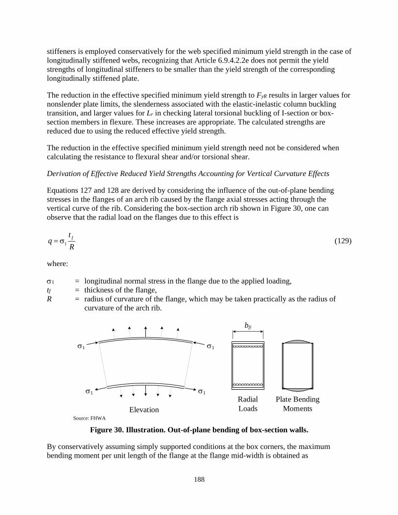
188
stiffeners is employed conservatively for the web specified minimum yield strength in the case of longitudinally stiffened webs, recognizing that Article 6.9.4.2.2e does not permit the yield strengths of longitudinal stiffeners to be smaller than the yield strength of the corresponding longitudinally stiffened plate.
The reduction in the effective specified minimum yield strength to FyR results in larger values for nonslender plate limits, the slenderness associated with the elastic-inelastic column buckling transition, and larger values for Lr in checking lateral torsional buckling of I-section or box-section members in flexure. These increases are appropriate. The calculated strengths are reduced due to using the reduced effective yield strength.
The reduction in the effective specified minimum yield strength need not be considered when calculating the resistance to flexural shear and/or torsional shear.
Derivation of Effective Reduced Yield Strengths Accounting for Vertical Curvature Effects
Equations 127 and 128 are derived by considering the influence of the out-of-plane bending stresses in the flanges of an arch rib caused by the flange axial stresses acting through the vertical curve of the rib. Considering the box-section arch rib shown in Figure 30, one can observe that the radial load on the flanges due to this effect is
1ft
qR
= σ (129)
where:
σ1 = longitudinal normal stress in the flange due to the applied loading, tf = thickness of the flange, R = radius of curvature of the flange, which may be taken practically as the radius of
curvature of the arch rib.
Source: FHWA
Figure 30. Illustration. Out-of-plane bending of box-section walls.
By conservatively assuming simply supported conditions at the box corners, the maximum bending moment per unit length of the flange at the flange mid-width is obtained as
σ1
σ1 σ1
σ1
bfi
ElevationRadial Loads
Plate Bending Moments

189
2 2
18 8fi f fiqb t qb
MR
= = σ (130)
where bfi is the flange width between the insides of the webs. Hence the maximum out-of-plane bending stresses at the top and the bottom of the flange plate are
2 12
3/ 6 4
fi fi
f f f
b bM MS t R t
σ = ± = ± = ± σ (131)
These out-of-plane bending stresses influence the onset of yielding in the flanges, and thus reduce the resistance of a member. The influence on the yielding at the surfaces of the flanges may be evaluated by considering the von Mises yield condition for the corresponding plane stress state, which may be written as
2 2 21 2 1 2 yFσ +σ −σ σ = (132)
neglecting the shear stresses within the flanges, which are addressed separately. Upon solving this quadratic equation for the value of σ1 corresponding to the onset of yielding at either surface of the flange, one obtains
2 221 2
32 4yFσ
σ = + − σ (133)
Upon substituting Equation 131 for σ2, one obtains
222 2
1 1 13 278 64
fifi fi fiy
ff
bb b bFtR t R
σ = ± σ + − σ
(134)
The value of σ1 satisfying this equation is the modified longitudinal stress at the onset of yielding of the surfaces of the flange at its mid-width. Although Equation 134 can be solved directly for the values of σ1 corresponding to the onset of yielding at the flange surfaces, a conservative and simpler equation form is obtained by substituting Fy for σ1 on the right-hand side of this equation:
22
13 2718 64
fifi fi fiy
ff
bb b bFtR t R
σ = ± + − (135)
The transverse bending of the flange plate effectively reduces the yield strength at one surface of the plate, and it increases the yield strength to a lesser extent at the opposite surface. The yield strength is unchanged, i.e., it is equal to Fy, at the mid-thickness of the plate. If the effective specified minimum yield strength of the plate is taken the average of these corresponding modified yield strengths, multiplied by 1.05, but not greater than Fy, recognizing the conservatism of the above substitution of Fy for σ1 on the right-hand side of Equation 134, and

190
the conservatism due to the variation of the transverse bending stresses through the width and the thickness of the plate, the result is
22271.05 164
fifiyR y y
f
bbF F FtR
= − ≤
(136)
The first term within the square brackets of Equation135 is canceled out by taking the average of the stresses. This is Equation 128 above.
For flange extensions of box-sections, I-section flanges, and web longitudinal stiffeners, the unsupported width of the plate is denoted by the variable b and the thickness of the plate is denoted by t. In this case,
2 2
12 2qb qbtM
R= = σ (137)
and
2 12 3/ 6
fi fi
f f f
b bM MS t R t
σ = ± = ± = ± σ (138)
By following the same process as the above, one obtains Equation 127.
The exact solution for σ1 from Equation 134, corresponding to initial yielding at the surfaces of the plate, may be written as
1 21yF
σ =± ξ + ξ
(139)
where
34
fi fi
f
b bR t
ξ = (140)
for box-section flanges, and
3 b bR t
ξ = (141)
for flange extensions of box-sections, I-section flanges, and web longitudinal stiffeners. If the reduced specified minimum yield strength is taken as 1.02 times the average of these corresponding yield strengths at the surfaces of the plate, but not greater than Fy, one obtains

191
2 2
1 10.51
1 1yR y yF F F += ≤ + ξ + ξ − ξ + ξ
(142)
Equations 127 and 128 above give approximately the same limit at which FyR becomes smaller than Fy as this equation.
3.5.2.2. Web Slenderness Requirements (Article 6.14.4.2)
Equation 6.14.4.2-1 is a not-to-exceed limit that ensures the web or webs of arch ribs are sufficiently stout such that they are capable of resisting transverse compression forces developed by the flanges acting through the vertical curve of the arch rib. This equation is adapted from the Eurocode Part 1-5 (CEN 2006) and AISC (2016) equations for the limit state of “flange induced buckling,” traditionally referred to in American structural engineering practice as flange vertical buckling. Equation 6.14.4.2-1 reduces to the corresponding equation in AISC (2016) in the limit that the radius of curvature of the arch rib, R, approaches infinity; this equation addresses the impact of the initial vertical curvature of the rib, in addition to the curvature due to bending, via the ratio R/D.
3.5.2.3. Nominal Flexural Resistance (Article 6.14.4.5)
For unbraced lengths in vertically curved members such as arch ribs, the lateral torsional buckling resistance of the member is reduced by the influence of the vertical curvature when the unbraced length is subjected to moments causing compression on the flange farthest from the center of curvature; that is, moments that tend to “straighten” the arch. The lateral torsional buckling resistance is increased by moments causing compression on the flange closest to the center of curvature; that is, moments that tend to increase the curvature of the arch. Increases in the lateral torsional buckling resistance due to these effects should be neglected. For typical unbraced lengths of box-section arch ribs with Ldb/R greater than 0.20, subjected to moments that would reduce the lateral torsional buckling resistance, 0.90 is a reasonable lower-bound on the reduction in the elastic lateral torsional buckling resistance. This reduction may be applied conservatively to the Cb modifier. The adjustment to the Cb modifier for arch ribs composed of doubly-symmetric open or closed sections may be determined more rigorously by a set of closed- form equations provided by Dowswell (2018). For arch ribs composed of singly-symmetric open or closed sections, the adjustment to the Cb modifier may be determined by solving equations provided by Trahair and Papangelis (1987).
3.6. OTHER PROVISIONS
3.6.1. Specification Provisions (Articles 6.7.4.4 and C6.1)
6.7.4.4—Noncomposite Box-Section Members
6.7.4.4.1−General
Diaphragms, where provided, should be connected to the webs and flanges of all noncomposite box-section members, where practical. The diaphragms shall be designed to resist cross-section distortion of the box and shall be designed to resist torsional moments in the box applied to or

192
resisted at the diaphragm location, and to transmit vertical and lateral forces from the box to the bearings, as applicable.
6.7.4.4.2− Square and Rectangular HSS Members
For all square and rectangular HSS members, placement of diaphragms at the member ends should be considered.
6.7.4.4.3−Welded and Nonwelded Built-Up Noncomposite Box-Section Members
Diaphragms shall be provided within welded and nonwelded built-up noncomposite box-section members at each support and at the ends of the member, unless the ends of the member are connected to other members that serve to retain the shape of the box cross-section. The placement of additional diaphragms at locations of any externally applied concentrated loads shall be considered.
An access hole at least 18.0 inch wide and 24.0 inch high, where practical, should be provided within each internal intermediate diaphragm. Design of the diaphragm shall consider the effect of the access hole on the stresses. Reinforcement around the hole may be required.
Where practical, cross-frames may be used in lieu of diaphragms at locations other than at supports. Connection plates for internal cross-frames shall satisfy the provisions of Article 6.6.1.3.1, as applicable.
In members subject to torsion in which:
0.2ve T cvf F> φ (6.7.4.4.3-1)
where:
ϕT = resistance factor for torsion specified in Article 6.5.4.2 fve = factored shear stress due to torsion in the cross-section element under consideration
(ksi) Fcv = nominal shear resistance of the cross-section element under consideration, under
shear alone, calculated as specified in Article 6.9.2.2.2 (ksi)
the spacing of internal intermediate diaphragms or cross-frames within the member should not exceed 40.0 feet. Internal intermediate diaphragms should be spaced a minimum of 2.0 feet apart.
6.7.4.5—Trusses and Arches
Diaphragms shall be provided at the connections to floorbeams and at other connections or points of application of concentrated loads in truss and arch members. Internal diaphragms may also be provided to maintain member alignment.
Gusset plates engaging a pedestal pin at the end of a truss shall be connected by a diaphragm. The webs of the pedestal should be connected by a diaphragm wherever practical.
193
If the end of the web plate or cover plate is 4.0 ft or more from the point of intersection of the members, a diaphragm shall be provided between gusset plates engaging main members.
C6.1—SCOPE
The LRFD provisions have no span limit. There has been a history of construction problems associated with curved bridges with spans greater than about 350 feet. Large girder self-weight may cause critical stresses and deflections during erection when the steel work is incomplete. Large lateral deflections and girder rotations associated with longer spans tend to make it difficult to fit up cross-frames. Large curved steel bridges have been built successfully; however, these bridges deserve special considerations such as the possible need for more than one temporary support in large spans.
Most of the provisions for proportioning main elements are grouped by structural action:
• Tension and combined axial tension, flexure, and flexural and/or torsional shear (Article 6.8)
• Compression and combined axial compression, flexure, and flexural and/or torsional shear (Article 6.9)
• Flexure, flexural shear, and torsion:
o I-sections (Article 6.10)
o Composite box sections (Article 6.11)
o Noncomposite box sections and other miscellaneous sections (Article 6.12)
Provisions for connections and splices are contained in Article 6.13.
Article 6.14 contains provisions specific to particular assemblages or structural types, e.g., through-girder spans, trusses, orthotropic deck systems, and arches.
For certain types of steel structures, benefits may be gained by applying advanced analysis methods for the design of the structure and/or its components. Using these methods, the member and structure stability are assessed using a second-order analysis directly considering initial geometric imperfections and residual stress effects. These methods provide greater rigor for consideration of innovative structural systems and member geometries. In addition, they provide capabilities for recognizing reserve capacities not addressed by the Section 6 provisions. Using these procedures, the members may be checked for their local “cross-section level” resistance given refined estimates of the internal strength demands as influenced by the member and overall system stability effects. These types of capabilities typically would be applied by focusing on a limited set of potentially critical factored design load combinations. Hendy and Murphy (2007) discuss the application of these types of methods in the context of steel bridge design according to the Eurocodes. Advanced analysis methods are an area of continued evolution as computer hardware and software continue to grow in their power and capabilities. Generally, advanced

194
analysis procedures must be calibrated to established physical test results considering appropriate nominal initial geometric imperfections and residual stresses.
3.6.2. Discussion
3.6.2.1. Diaphragm Requirements for Noncomposite Box-Section Members (Article 6.7.4.4 and Article 6.12.2.2.2a)
For welded and nonwelded built-up noncomposite box-section members subject to torsion, cross-sectional distortion stresses are controlled by internal diaphragms or cross-frames. As specified in Article 6.12.2.2.2a, factored transverse plate bending stresses due to cross-section distortion should be limited to 20.0 ksi at the strength limit state in noncomposite box-section members subject to large torques.
Holes may be provided in diaphragms of HSS members to accommodate functions such as drainage, hot dip zinc coating, utilities, and access to connections.
Diaphragms acting as flexural members over supports in larger noncomposite box-section members, or when connecting multiple noncomposite box-section members, should also satisfy the applicable requirements of Article 6.7.4.3.
Where practical, access holes in internal intermediate diaphragms should be wide and high enough to allow for convenient maintenance and inspection access. The holes should be placed in the diaphragms in a position that will allow convenient access when passing through the box. Any stiffeners on the diaphragms should be placed back from the edges of the openings,
Section 3.1.2.13 discusses special moment of inertia requirements for top or bottom struts of internal intermediate cross-frames that serve as transverse stiffeners to enhance the compressive resistance of a longitudinally stiffened plate element.
The factored torsional shear stresses in Equation 6.7.4.4.3-1, fve, may be computed using the appropriate equation given in Section 3.3.2.2 in lieu of a refined analysis
3.6.2.2. Recognition of Advanced Analysis Methods (Article C6.1)
A brief description of advanced analysis methods is recommended for the Commentary of Article C6.1. It is important to note that “advanced analysis” and “refined analysis” are not synonymous. The key distinction between these two types of analysis is that advanced analysis has the capability of directly assessing certain specified strength limit states such that, if the analysis shows that the structure or structural assembly supports the required loads, separate checking via member resistance equations is superseded. The term refined analysis implies a level of analysis that accurately captures the key three-dimensional attributes of the structural system, typically within the context of an elastic idealization of the material response. Refined analysis methods do not necessarily provide a sufficient assessment of strength limit states in and of themselves. They are commonly combined with the use of Specification equations for checking of resistances.

195
Advanced analysis is an area of continued research development and evolution. At the high end, these methods involve test simulation procedures in which the plate elements of the structure are typically modeled using shell finite elements, initial nominal geometric imperfections and residual stresses are defined within the finite element model, the spread of plasticity through the volume of the structural components is tracked explicitly, and the geometric nonlinear (stability) response of the structure and its various components is captured rigorously. The term advanced analysis also commonly refers to procedures in which certain attributes of selected component structural responses may be modeled in a simplified manner, based on certain assumptions or classifications of the behavior, but with the overall goal of still fully capturing the complete limit states response of the structure at some level. For example, a common advanced analysis assumption in some areas is to assume compact and nonslender cross-section plate element behavior, such that the influence of plate stability effects may be neglected within the overall analysis. Such approaches are not capable of capturing the limit states response of members composed of slender and/or longitudinally stiffened plates.
196
CHAPTER 4 - CONCLUSIONS
4.1. SUMMARY
As stated in the introduction chapter, the objective of this research is the development of updated and unified AASHTO LRFD provisions for the design of noncomposite steel box-section members. This effort is focused on achieving greater consistency between the steel design provisions within the AASHTO LRFD Specifications, as well as improved accuracy, generality, and ease of use of the AASHTO LRFD rules.
The following specific developments support these broad objectives:
(1) A form of the unified effective width approach (Peköz, 1987; Ziemian, 2010; AISI, 2016; AISC, 2016) is implemented to quantify the postbuckling resistance of slender plates subjected to uniform axial compression and their contribution to overall member axial compressive and flexural resistances. The unified effective width approach is more succinct and generally more accurate compared to the traditional Q factor approach employed in earlier AISI, AISC and AASHTO Specifications. The unified effective width procedure in AISC 360-16 takes up less than two pages of the Specification where the former Q factor approach required four pages.
(2) A simple shift in the ordinate of Winter’s effective width equation is defined to provide an improved quantification of the resistance of slender welded plate elements subjected to uniform axial compression. This modified curve gives results similar to an alternative exponential equation form recommended by Schillo (2017) as well as a multi-part equation form implemented in BS 5400-3:2000 (BSI, 2000). An existing variation on Winter’s base effective width equation from AISC (2016) and AASHTO (2015) is recommended to characterize the resistance of slender elements in square and rectangular hot-formed HSS and for flanges and webs of non-welded built-up box-sections. The base form of Winter’s equation from AISI (2016), with an inherent assumed buckling coefficient of kc = 4.0, is recommended as the representation for cold-formed square and rectangular HSS.
(3) Two new equations are recommended to characterize the flexural resistance of noncomposite longitudinally unstiffened box-section members. The first equation captures the “plateau” resistance of these types of members. The second equation is a simple linear interpolation equation that captures the strength reduction relative to the plateau resistance due to lateral-torsional buckling. These two equations provide simplicity of the design calculations while recognizing the combined influence of flange slenderness, web slenderness and overall member lateral bending and St. Venant torsional rigidity on the flexural resistance of these types of members. These equations also recognize the ability of box-section members to develop resistances up to the fully-plastic resistance of the cross-section, given sufficient width-to-thickness of the cross-section plate elements. The recommended formulation relaxes the compactness requirements relative to the traditional AISC (2016) values by focusing on “Class 2” behavior, i.e., ability to develop the plastic moment resistance but without necessarily providing sufficient ductility for plastic design. For cross-sections containing a slender
197
compression flange or slender web plates, the postbuckling resistance of the slender plates is recognized. Plateau resistances between the effective yield moment and the effective plastic moment are captured for box-sections with noncompact webs. In addition, singly-symmetric as well as hybrid box-sections are accommodated. Lastly, the ability of singly symmetric box-sections to develop significant yielding in flexural tension is recognized by the recommended formulation. This attribute can be potentially very beneficial, particularly with the extension of this calculation procedure to box-sections with longitudinally stiffened compression flanges, discussed below.
(4) A new approach for the design of longitudinally stiffened plates subjected to compression, with or without transverse stiffeners, is recommended. This approach characterizes a wide range of the behavior and corresponding strengths of longitudinally stiffened plates using an intuitive and straightforward column on elastic foundation idealization. The formulation of the equations includes the contribution from the flexural rigidity of the stiffener struts (the longitudinal stiffeners plus the plate tributary to the stiffeners) as well as the contributions from plate transverse bending and plate torsion. These contributions can be significant for common longitudinally stiffened plates with only one or two longitudinal stiffeners. The postbuckling resistance of slender longitudinally stiffened plate panels is also addressed. For wider plates with larger numbers of longitudinal stiffeners, the method directly provides the buckling characteristic length without transverse stiffeners, facilitating the choice of spacing of transverse stiffeners or diaphragms to increase the plate strength.
(5) Specific requirements are provided to avoid early yielding of longitudinal stiffeners, local buckling of the component plates in longitudinal stiffeners, and torsional buckling of longitudinal stiffeners about their edge connected to the stiffened plate (i.e., tripping failure), and detailed guidance is provided for detailing of the longitudinal stiffeners within the discussion of these provisions.
(6) Comprehensive provisions are provided characterizing the stiffness, strength and detailing requirements for transverse stiffeners in longitudinally stiffened plates. An alternative design procedure, in which the transverse stiffener is sized directly as a beam or beam-column member, is recommended within the discussion of these provisions to avoid the ordinary simplified rules preventing tripping failure of the transverse stiffeners from becoming prohibitive in large box-section members where the cross-section of the transverse stiffener will need to be other than a flat plate to adequately satisfy the stiffness and strength demands.
(7) The above procedure for calculation of the longitudinally stiffened plate resistances is implemented as an equivalent yield load calculation in conjunction with the unified effective width method to quantify the axial compressive resistance of members containing any combination of longitudinally stiffened, slender longitudinally unstiffened plates, and nonslender longitudinally unstiffened plates within a box-section as well as other types of members. For relatively slender box-section members containing longitudinally stiffened flange plates with slender panels, the test simulation studies conducted in this research indicate that more conservative column strength
198
curve is needed to account for the local-global buckling interaction. A local-global strength interaction reduction factor is recommended to capture this behavior.
(8) The above procedure for calculation of the longitudinally stiffened plate resistances is implemented within the recommended procedures from development (3) to characterize the flexural resistance of box-section members having longitudinally stiffened compression flanges. This is accomplished by representing the longitudinally stiffened compression flange as a zero-thickness effective area “strip” located at the centroid of the gross area of the entire flange. Furthermore, in recognition of the typical limited ability of longitudinally stiffened plates to withstand inelastic deformations without a significant loss of strength, box-section members with a longitudinally stiffened compression flange are categorized as slender web sections, i.e., their calculated plateau resistance is never larger than the effective yield moment to the effective compression flange.
(9) For box sections with longitudinally stiffened webs, new provisions adopted by the AASHTO CBS in 2017 for the 2020 9th Edition of the AASHTO LRFD Specifications are utilized. These provisions define a larger web bend buckling strength reduction factor, Rb, for longitudinally stiffened webs that accounts for the influence of web longitudinal stiffeners on the web postbuckling response and shedding of stresses predominantly to the compression flange.
(10) The recommended Articles 6.9.2.2 and 6.8.2.3 are substantially updated and enhanced in the proposed AASHTO LRFD Specifications to improve their accuracy, and to provide ease of use in addressing a wide range of different force interaction effects that can be particularly important for box-section members. Interaction between axial tension yielding, tension rupture or compression, uniaxial or biaxial bending, and flexural and/or torsional shear is addressed in these updated provisions. The more complex interactions with flexural and torsional shear are placed in a sub-article, and the interactions are expressed in terms of reduction factors, ∆, ∆x and ∆y, on the axial and flexural resistances, to maintain the simplicity of the interaction equations as much as possible. In addition, exclusion clauses are provided that remove the requirements for checking of flexural and/or torsional shear strength interactions when the magnitudes of specific strength ratios are sufficiently small. Optional interaction equations are provided that allow the engineer to account for beneficial influence of axial tension on compression buckling limit states, in specific situations. A generalized form of interaction equations from AISC (2016) is provided that recognizes a separate interaction relationship for tension rupture at a net cross-section due to flexure combined with axial tension or compression, versus tension yielding combined with lateral torsional buckling of the overall member unbraced length.
(11) The recommended provisions have adopted and generalized the design philosophy from Articles 6.10 and 6.11 of AASHTO LRFD that theoretical elastic plate buckling is disallowed at service limit states, and for constructibility, for component plate elements supported along two longitudinal edges.
199
(12) The recommended Article 6.14.4, addressing the design of solid web arches, is completely rewritten to take advantage of the above advancements. This results in a substantial increase in calculated overall arch rib resistances relative to prior equations based on equating applied stresses to the yield strength of the material within slender and compact plate buckling limit equations. Equations and guidance are provided to account for strength reductions due to the influence of arch rib vertical curvature on plate and lateral-torsional buckling resistances. Recommended not-to-exceed b/t limits are provided for arch rib flanges and webs to avoid significant impacts of vertical curvature on the structural resistances.
(13) The current AASHTO LRFD (AASHTO, 2017) shear strength rules are adopted throughout the above updated provisions with the exception that optional improved shear buckling coefficients are provided for longitudinally stiffened flange plates.
(14) Highly simplified shear lag flange effective width reductions are adopted in the recommended flexural resistance equations for the characterization of member ultimate strengths. These reductions enter into the flexural resistance calculations only when the box-section member flanges become extraordinarily wide compared to the effective span length, taken equal to the full span length for simple-span members, the distance between the inflection points in positive or in negative bending under the component dead load for continuous-span members, the distance between the simple support and the inflection point under the component dead load for end spans of continuous-span members, and two times the length from the support to the location of zero moment for cantilever spans. More detailed shear lag flange effective width reduction equations are provided for the calculation of elastic flexural stresses at the service and fatigue limit states, in lieu of a more rigorous analysis, within the negative moment regions of continuous-span members, and within cantilevers.
(15) The recommended provisions for design of diaphragms and for calculation of stresses due to box-section member distortion largely adopt and utilize the corresponding simplified rules provided in the current AASHTO LFRD Specifications for composite box-section members.
(16) Guidance for more advanced calculations, to better account for the general strength limit states of all types of members, and specifically to better address nonprismatic members and/or other more general box cross-section geometries, is provided within the discussion of the recommended provisions.
4.2. FUTURE RESEARCH NEEDS
The present research has provided a relatively comprehensive synthesis and advancement of the state-of-the-art regarding the design of all types of noncomposite box-section members in bridge design. Nevertheless, there are a number of related areas that merit further study:
• Regarding the above developments (2) and (4), the current research has adopted a relatively simple characterization of the influence of in-plane lateral restraint from adjacent panels in longitudinally stiffened plates. The more optimistic nonslender plate
200
limit and effective width imperfection adjustment factors given in Table 18 and 19 are employed for flanges and webs of built-up box-sections containing two or more longitudinal stiffeners as a simple approximation. This results in relatively conservative predictions of the axial compressive resistance of longitudinally stiffened plates for larger panel width-to-thickness ratios, as shown in Figure 10, and also some of the more conservative predictions for member axial compressive strengths in Figure 14 and for member flexural resistances (aside from the tests with large awce in Figure 17 and 18). It may be worthwhile to provide a more detailed quantification of these in-plane lateral restraint effects. In particular, it is apparent that the influence of these effects varies depending on whether one or both longitudinal edges of a given panel are bounded by an adjacent longitudinally stiffened panel.
• Regarding development (3), the recommended provisions have focused on the predominant cases of box-section members where the flanges, for a given direction of bending, are parallel to the corresponding principal axis of the cross-section. Potential extensions have been dicussed to address cases such as octagonal, parallelogram or trapezoidal box-section geometries, where for a particular principal bending direction, the flange elements are subjected to a gradient in the corresponding flexural stresses rather than uniform flexural compression. A number of additional complexities exist for these more general box-section members, as discussed in Section 3.2.2.1. These geometries should be given further attention, with the goal of providing additional design guidance.
• Regarding development (4), the recommended provisions quantifying the axial compressive resistance of longitudinally stiffened plates provide simple conservative adaptations of the equations derived for equally-spaced equal-size longitudinal stiffeners for cases involving unequally-spaced and/or unequal-size longitudinal stiffeners. Appendix 1 of AISI (2016) and Ziemian (2010) provide expressions quantifying the elastic plate buckling resistance for uniformly compressed longitudinally stiffened plates with stiffeners of arbitrary size, location and number. These expressions reduce to the elastic buckling equations based on orthotropic plate theory employed in the recommended developments in the limit that the longitudinal stiffeners are of the same size and are equally spaced. The applicability of these equations and the improvements they may offer for general unequally-spaced unequal-size longitudinal stiffener configurations should be investigated.
• Regarding developments (4) and (5), the recommended equations quantifying the axial compressive resistance of longitudinally stiffened plates ignore the torsional stiffness contributions from the longitudinal stiffeners themselves. These contributions are relatively small for flat plate and Tee section stiffeners. However, they can be more substantial for closed-section longitudinal stiffeners. The additional benefits gained by including the torsional rigidity of closed-section longitudinal stiffeners in the equations for the plate compressive strength should be considered. In addition, further unification of the recommended provisions with the orthotropic deck design requirements in AASHTO (2017) and Connor et al. (2012) should be considered. Furthermore, as discussed in Section 3.1.2.10, the recommended Equation E6.1.4-2, which is considered most appropriate for new design, neglects the potential restraint from the stiffened plate to twisting of the stiffener about its connection to the plate. Further research should be
201
conducted to evaluate prior recommendations to quantify this restraint and provide simple rules that account for this restraint.
• Regarding development (7), the current research has addressed the calculation of the axial compressive resistance of members containing slender longitudinally unstiffened plates and/or longitudinally stiffened plates by a combination of the equivalent yield load based and unified effective width based procedures. Although it is clear that the postbuckling behavior of longitudinally stiffened plates and of slender longitudinally unstiffened plates can be very different, it may be possible to unify these two approaches into a single more conceptually consistent procedure for calculation of member axial compressive resistances. The characteristics of each of these design calculations should be thoroughly scrutinized and compared to better understand how they work in quantifying the axial compressive resistances of members composed of these two types of plates.
• Regarding developments (1) through (6), and developments (8) and (9), there are various improvements within the recommended provisions for design of noncomposite box-section members that can be applied to gain significant gains in the accuracy, generality and ease of use of the AASHTO LRFD provisions for design of composite box-section flexural members. A separate effort should be considered to update the AASHTO composite box-girder provisions as appropriate, given the advances in this research.
• The recommended force-interaction rules in development (10) provide a major improvement in the ability to characterize the resistance of box-section as well as other types of members subjected to general combined loadings. Although it is anticipated that further advancements in quantifying the various strength interactions are likely to involve substantial increases in complexity, further detailed study of these strength interactions may indeed provide further gains in accuracy and/or simplicity. Ultimately, the greatest potential for combined simplicity and rigor of assessment may lie in the further development, validation and implementation of advanced analysis procedures.
• Regarding development (12), specific guidance has been provided for calculation of the lateral-torsional buckling resistance of arch ribs, with reference to Dowswell (2018) and Trahair and Papangelis (1987), in the discussion of the recommended Specification provisions. A simple multiplicative reduction on Cb of 0.9 is recommended for the Article 6.14.4.6 Specification provisions for box-section arch ribs. The calculation procedures discussed by Dowswell (2018) and by Trahair and Papangelis (1987) potentially can be implemented as specification provisions. This development is recommended for further research.
• As noted in Section 2.1.5 of this report, the shear strength of unstiffened webs becomes substantially larger than the theoretical shear buckling resistance as the web plates become more slender. These additional shear resistances are due to the shear postbuckling behavior of these types of plates. These additional shear strengths are recognized in the Eurocode 3 Part 2 (CEN, 2006a) provisions for steel bridge design, and they are recognized in the AISC (2016) Specification Section G2.1. Pertaining to development (13), the potential consideration of these larger shear strengths within the
202
AASHTO LRFD Specifications should be evaluated. In conducting these evaluations, the potential strength interactions between flexural shear and other loading effects should be addressed, including the current and recommended improved calculations of member axial and flexural resistances.
• As noted in Sections 2.2.6 and 3.2.2.1, there are wide variations in the flange plate effective width rules that are intended to quantify shear lag effects in different standards and guidelines documents at the present time. The actual structural members are not aware of these variations. Pertaining to development (14), a thorough study is needed to evaluate the bases for the different characterizations of shear lag effects, with a goal of unification of the guidelines and rules. This is another area where, ultimately, some of the most important advances in simplicity and accuracy may indeed be in the development and application of appropriate refined analysis methods.
• Regarding development (15), Section 2.1.7 of this report provides a detailed discussion of the current state-of-the-art regarding diaphragm design requirements as well as current code-based and refined analysis based calculations of local plate bending stresses and longitudinal warping stresses due to box cross-section distortion. This is also an area where refined analysis procedures may ultimately provide the greatest combination of simplicity and accuracy. Research with a specific focus on improving the calculation of these effects may prove to be very beneficial.
• Pertaining to development (16), Sections 3.2.2.1 and 3.3.2.1 of this report discuss the extension of the AASHTO LRFD prismatic member design rules to address nonprismatic member geometries. AISC provides detailed guidance extending the design provisions of AISC 360-16 in its Design Guide 25 (Kaehler et al., 2018). Although many of the concepts in this design guide are general in nature, the primary focus of this guide is the design of metal building frames. A comparable guide should be developed with a specific focus on the design of bridge structures, including the design of variable web depth and stepped girder geometries, as well as more general application of nonprismatic member design principles to arches and towers.
• Lastly, although the validation and testing of the recommended AASHTO LRFD provisions has been extensive, additional validation and testing may lead to further improvements. New experimental testing can provide additional data useful to detailed assessment of the underlying level of reliability associated with the calculations. Specific areas where additional studies might be focused include:
o Flexure of longitudinally unstiffened box-section members with a specific focus on the interaction between local plate postbuckling response and overall member lateral-torsional buckling,
o Axial compression of members composed of longitudinally unstiffened slender plates and/or longitudinally stiffened plates, particularly for larger column slenderness and larger plate panel b/t values, with a specific focus of improving the understanding of local-global strength interaction regarding member axial

203
compressive strengths. Experimental testing of these types of members would likely need to be conducted at a reduced scale to be feasible.
o Flexural resistance of box-section members with longitudinally or longitudinally unstiffened flanges having large awce values approaching 10 or above and longitudinal stiffeners placed such that ds/Dce approaches and exceeds 0.76. These types of tests will be useful to provide further validation of strain-compatibility based calculations that reduce the level of conservatism of the recommended routine calculations for these extreme cases.
204
APPENDIX A - FLOWCHARTS OF SPECIFICATION PROVISIONS
A.1 INTRODUCTION
Appendix A provides proposed Specification flowcharts for the calculation of noncomposite box-section member compression and flexural capacities. The flowcharts focus on these portions of the proposed Specifications because they are the major focus of the research and contain the most involved sets of new equations. The flowcharts are for welded noncomposite rectangular box-sections. The process varies for HSS and mechanically fastened built-up box-sections. Each step in the flowcharts is numbered within brackets using the prefix ‘C’ for compression and ‘F’ for flexure (e.g. [C1] and [F1]). These steps are called out with bold type in the example calculations of Appendix B where they occur to correlate the two appendices.
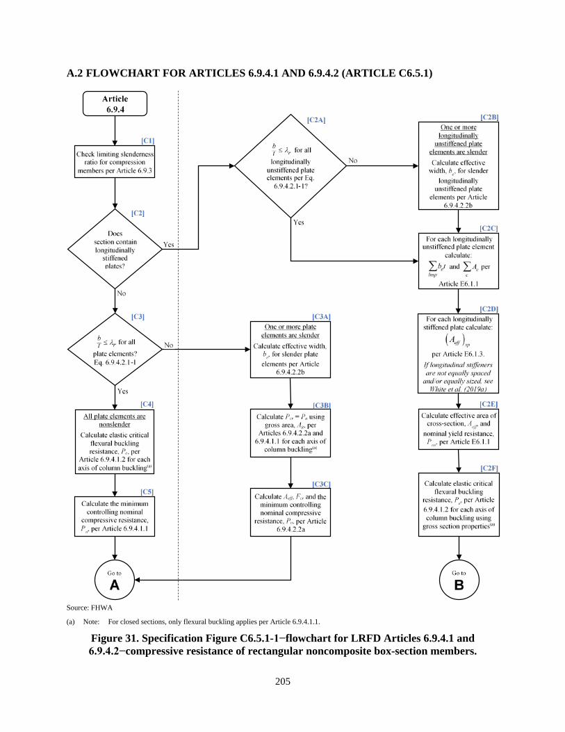
205
A.2 FLOWCHART FOR ARTICLES 6.9.4.1 AND 6.9.4.2 (ARTICLE C6.5.1)
Source: FHWA
(a) Note: For closed sections, only flexural buckling applies per Article 6.9.4.1.1.
Figure 31. Specification Figure C6.5.1-1−flowchart for LRFD Articles 6.9.4.1 and 6.9.4.2−compressive resistance of rectangular noncomposite box-section members.

206
Source: FHWA
Note (a): If member is subject to uniaxial flexure only and Pu/Pr is less than or equal to 0.05, follow the ‘No’ path
Figure 32. Specification Figure C6.5.1-1−flowchart for LRFD Articles 6.9.4.1 and 6.9.4.2−compressive resistance of rectangular noncomposite box-section members
(continued).
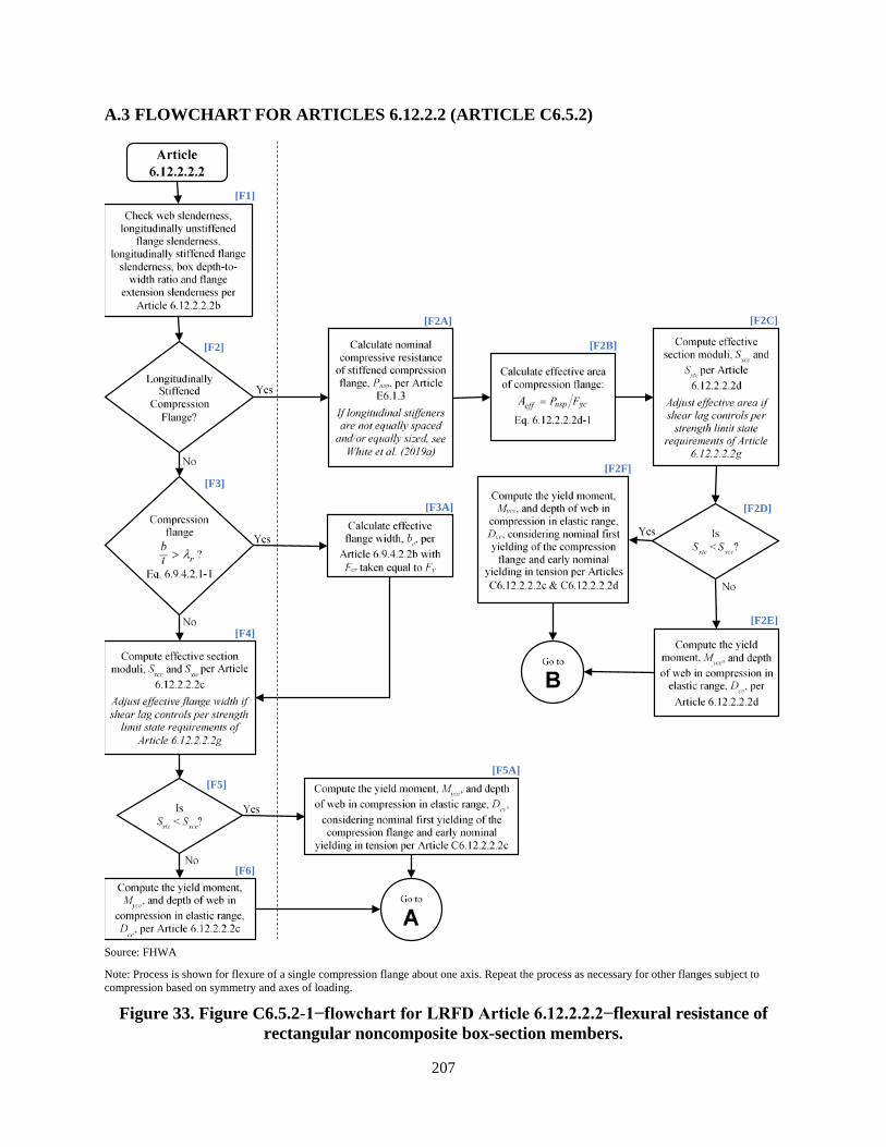
207
A.3 FLOWCHART FOR ARTICLES 6.12.2.2 (ARTICLE C6.5.2)
Source: FHWA
Note: Process is shown for flexure of a single compression flange about one axis. Repeat the process as necessary for other flanges subject to compression based on symmetry and axes of loading.
Figure 33. Figure C6.5.2-1−flowchart for LRFD Article 6.12.2.2.2−flexural resistance of rectangular noncomposite box-section members.
[F1]
[F2] [F2A]
[F2B]
[F2C]
[F3A]
[F2F]
[F2E] [F4]
[F6]
[F5A]
[F3] [F2D]
[F5]
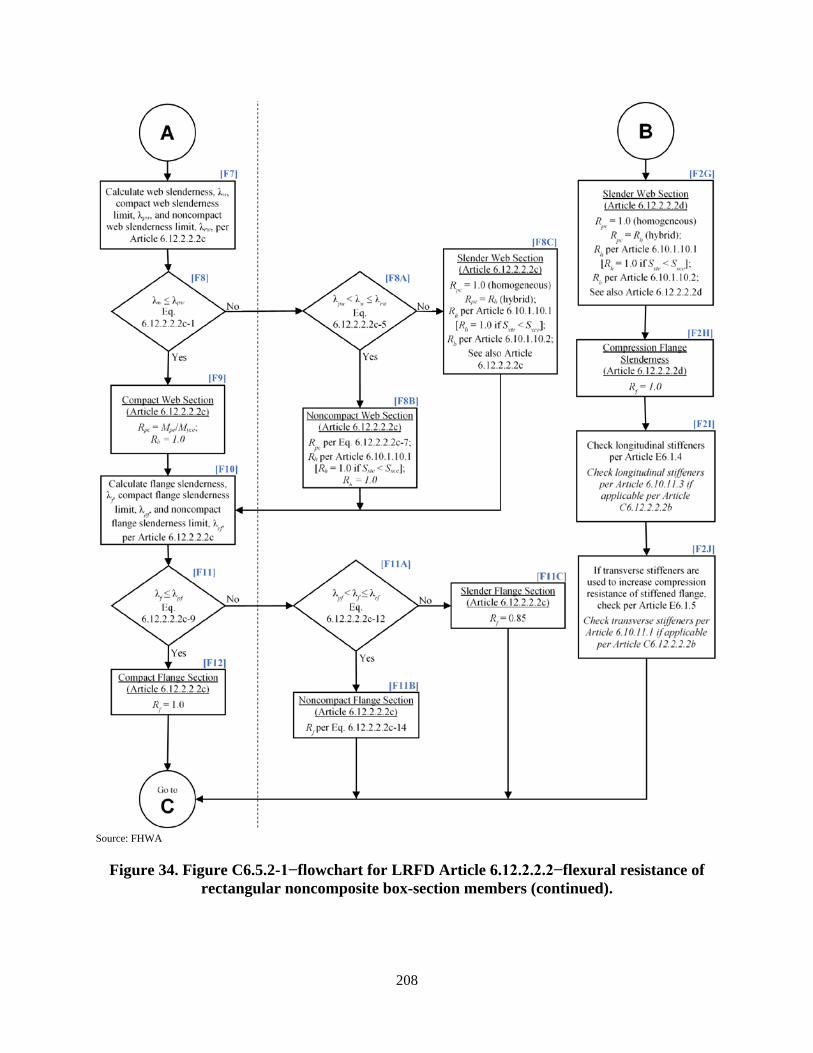
208
Source: FHWA
Figure 34. Figure C6.5.2-1−flowchart for LRFD Article 6.12.2.2.2−flexural resistance of rectangular noncomposite box-section members (continued).
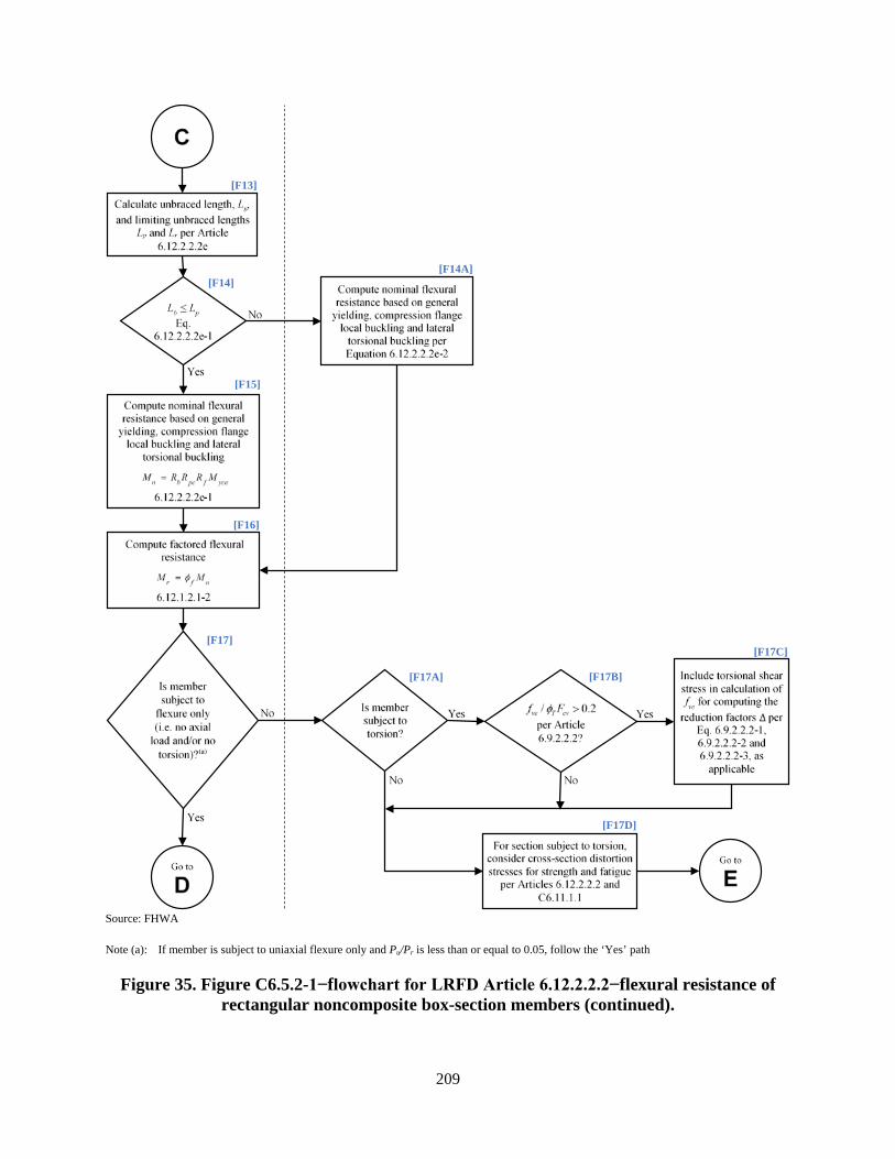
209
Source: FHWA
Note (a): If member is subject to uniaxial flexure only and Pu/Pr is less than or equal to 0.05, follow the ‘Yes’ path
Figure 35. Figure C6.5.2-1−flowchart for LRFD Article 6.12.2.2.2−flexural resistance of rectangular noncomposite box-section members (continued).
[F13]
[F14] [F14A]
[F15]
[F16]
[F17C]
[F17D]
[F17]
[F17A] [F17B]

210
Source: FHWA
Figure 36. Figure C6.5.2-1−flowchart for LRFD Article 6.12.2.2.2−flexural resistance of rectangular noncomposite box-section members (continued).
[F18] [F17E]
[F17F]

211
APPENDIX B - EXAMPLES
B.1 GENERAL INFORMATION
Appendix B provides cross-section examples for three different types of noncomposite rectangular steel box members to demonstrate the use of the proposed specification changes to the current AASHTO Bridge Design Specifications, 8th Edition, September 2017 (AASHTO). The adoption of the work in this report into the specifications is an incremental process. A portion of this work, addressing slender plate elements in axial compression, has been balloted and included in the 8th Edition. Additional portions of the report, addressing longitudinally unstiffened boxes in flexure, have been balloted and approved for inclusion in the 2020 9th Edition of AASHTO. Finally, modifications and provisions addressing longitudinally stiffened boxes and miscellaneous items will be presented for ballot and inclusion as well into the 2020 9th Edition of AASHTO. The specifications, equations and numbering presented in this report and appendices are based on the proposed ballots at the time of this writing. The final specifications that are adopted into the 2020 9th Edition of AASHTO may vary somewhat from those presented here.
The three examples in this appendix illustrate the design of welded noncomposite box-section members, which are the most common form of noncomposite box-section members for new bridge structure designs. However, the proposed specifications do accommodate HSS members and mechanically fastened built-up boxes using the same basic principles with some modifications, as necessary. The three examples provided include:
a. Truss end post: This welded nonslender longitudinally unstiffened member is subjected to axial compression, biaxial bending, flexural and torsional shear to demonstrate the basic principles using the least complex, and most common, type of noncomposite box-shaped member. The second and third examples cover more complex cross-sections. After completion of the design, a discussion of the modifications necessary for the use of HSS for the end post will be presented.
b. Tied arch tie girder: This welded slender longitudinally stiffened web member with different thickness hybrid flanges is subjected to axial tension, biaxial bending, flexural and torsional shear. The design includes sizing of longitudinal and transverse plate stiffeners. The optional use of angle or tee-shaped longitudinal stiffeners is also presented.
c. Arch rib compression member: This welded member with slender longitudinally stiffened webs is subjected to compression, biaxial flexure, flexural and torsional shear. This abbreviated example demonstrates the requirements for solid web arch members specified in Article 6.14.4.
As stated, these examples focus on the provisions modified by the content of this report. These include, but are not limited to:
• Article 6.7.4.4 for diaphragms in noncomposite box-section members
• Article 6.8.2.3 for combined tension, flexure, and flexural and torsional shear
212
• Article 6.9.2.2 for combined axial compression, flexure, and flexural and torsional shear
• Article 6.9.4.5 for service and fatigue limits states and constructibility of member cross-sections composed of slender plate elements or slender longitudinally stiffened plate panels
• Article 6.9.4.1 for nominal compressive resistance
• Article 6.9.4.2 for effects of local buckling on compressive resistance
• Article 6.12.1.2 for the strength limit state of miscellaneous flexural members
• Article 6.12.2.2.2 for the nominal flexural resistance of rectangular box-section members
• Article 6.14.4 for solid web arch members
• Appendix E6 for compressive resistance of noncomposite members containing longitudinally stiffened plates
A complete design, however, must consider the additional applicable requirements included in Section 6 as well as those in Sections 1, 2, 3 and 4. AASHTO Appendix C6 provides a generic overview of the design process for steel bridge superstructures. These examples are concerned with the design of rectangular box sections at the cross-sectional level. It is the responsibility of the design engineer to perform the proper analysis for the complete design of the structure. These examples contain a limited discussion of diaphragms in regards to acting as transverse stiffeners for longitudinally stiffened plates and resisting warping of the cross-section.
Note that these examples, for brevity, use the envelope of controlling force effects over all load combinations within a limit state and do not, as a proper design should at a minimum, compute maximum enveloped forces for each load combination applicable to the limit state in question and check them separately. That is, only using concurrent sets of forces for the maximum and minimum of each force effect may not be the controlling case. As discussed in Article C6.9.2.2.1, a set of concurrent loads, which are not based on a maximum or minimum, may produce the critical combined effect on the cross-section. Design loads provided for these examples are taken from the analyses of a similar structures and are only intended as comparable load conditions for these cross-sections.
Finally, refer to Appendix A of this report for proposed Specification flowcharts that show the steps for calculating compression and flexural resistances in accordance with the proposed Specifications. Each step in the flowcharts is numbered within brackets using the prefix ‘C’ for compression and ‘F’ for flexure (e.g. [C1] and [F1]). These steps are called out with bold type in the example calculations of Appendix B where they occur. These examples are for complete designs that include more than compression and flexure about one single axis; as such, the example calculations may not be in the same numerical order as the flowcharts.
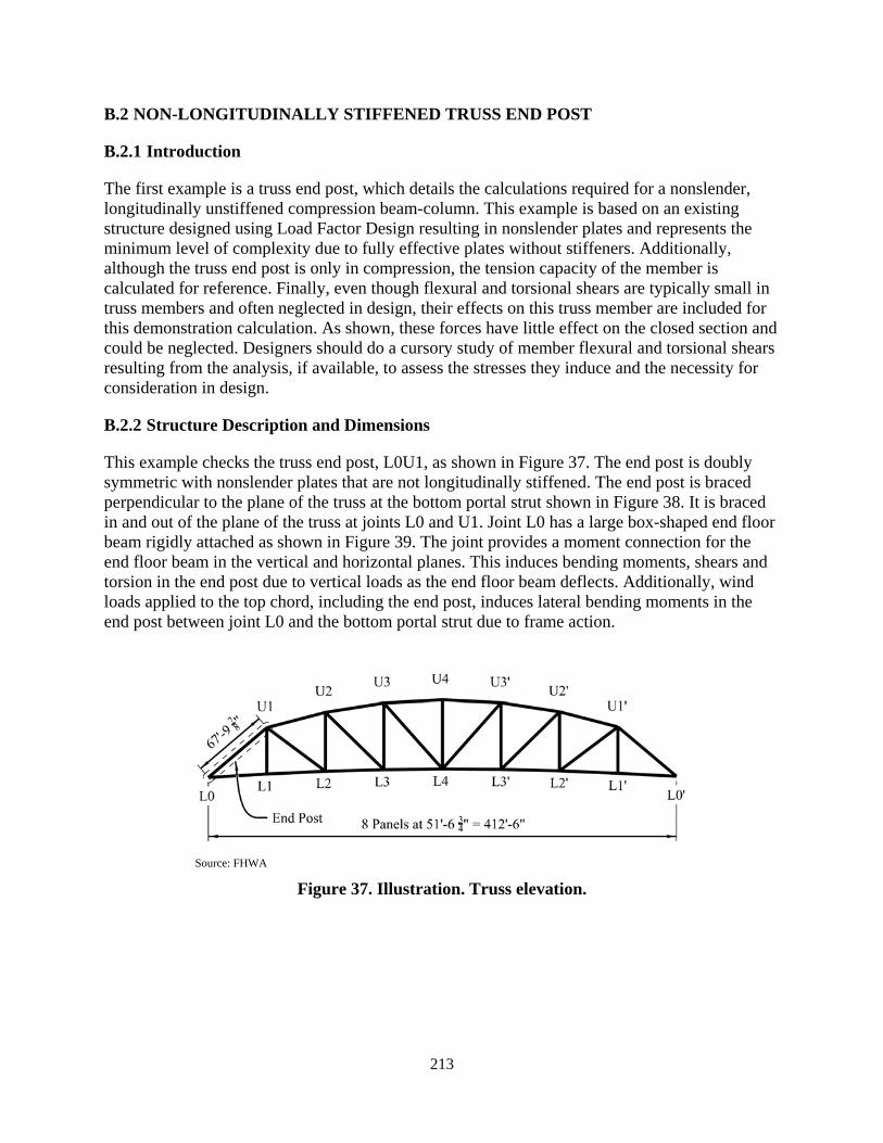
213
B.2 NON-LONGITUDINALLY STIFFENED TRUSS END POST
B.2.1 Introduction
The first example is a truss end post, which details the calculations required for a nonslender, longitudinally unstiffened compression beam-column. This example is based on an existing structure designed using Load Factor Design resulting in nonslender plates and represents the minimum level of complexity due to fully effective plates without stiffeners. Additionally, although the truss end post is only in compression, the tension capacity of the member is calculated for reference. Finally, even though flexural and torsional shears are typically small in truss members and often neglected in design, their effects on this truss member are included for this demonstration calculation. As shown, these forces have little effect on the closed section and could be neglected. Designers should do a cursory study of member flexural and torsional shears resulting from the analysis, if available, to assess the stresses they induce and the necessity for consideration in design.
B.2.2 Structure Description and Dimensions
This example checks the truss end post, L0U1, as shown in Figure 37. The end post is doubly symmetric with nonslender plates that are not longitudinally stiffened. The end post is braced perpendicular to the plane of the truss at the bottom portal strut shown in Figure 38. It is braced in and out of the plane of the truss at joints L0 and U1. Joint L0 has a large box-shaped end floor beam rigidly attached as shown in Figure 39. The joint provides a moment connection for the end floor beam in the vertical and horizontal planes. This induces bending moments, shears and torsion in the end post due to vertical loads as the end floor beam deflects. Additionally, wind loads applied to the top chord, including the end post, induces lateral bending moments in the end post between joint L0 and the bottom portal strut due to frame action.
Source: FHWA
Figure 37. Illustration. Truss elevation.

214
Source: FHWA
Figure 38. Illustration. Truss end view.
Source: FHWA
Figure 39. Illustration. Joint L0 - inside view
The member does not contain access holes in the portion between the connections. Bolt holes are drilled to size for one-inch diameter bolts. The critical net section is located at the joint L0 gusset connection, where the end post is connected with seven bolts in each web plate. The end post is fabricated with AASHTO M270 Grade 50 steel, which has the following material properties:
50 ksiyF = Table 6.4.1-1
65 ksiuF = Table 6.4.1-1
29,000 ksiE = Article 6.4.1
0.385 11,165 ksiG E= = Article 6.9.4.1.3
B.2.3 Force Effects
The controlling unbraced length for L0U1 is the portion between joint L0 and the bottom portal strut, which has the largest slenderness values. The combined axial and flexural checks should be based on the combination of maximum flexural forces in each bending direction, independent of their location along their controlling unbraced length. This ensures that the maximum combination of force effects along the length of the member is covered as discussed in the commentary for Article 6.9.2.2.1. For L0U1, all maximum effects occur at the joint L0 end.
The structure is subjected to:
• permanent dead loads including structural steel, DC;
• future wearing surface and utilities, DW;
• wind on structure for various load combinations, WS;
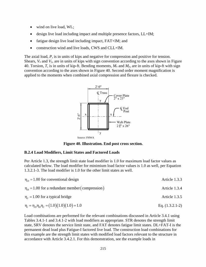
215
• wind on live load, WL;
• design live load including impact and multiple presence factors, LL+IM;
• fatigue design live load including impact, FAT+IM; and
• construction wind and live loads, CWS and CLL+IM.
The axial load, P, is in units of kips and negative for compression and positive for tension. Shears, Vx and Vy, are in units of kips with sign convention according to the axes shown in Figure 40. Torsion, T, is in units of kip-ft. Bending moments, Mx and My, are in units of kip-ft with sign convention according to the axes shown in Figure 40. Second order moment magnification is applied to the moments when combined axial compression and flexure is checked.
Source: FHWA
Figure 40. Illustration. End post cross section.
B.2.4 Load Modifiers, Limit States and Factored Loads
Per Article 1.3, the strength limit state load modifier is 1.0 for maximum load factor values as calculated below. The load modifier for minimium load factor values is 1.0 as well, per Equation 1.3.2.1-3. The load modifier is 1.0 for the other limit states as well.
1.00 for conventional designDη = Article 1.3.3
( )1.00 for a redundant member compressionRη = Article 1.3.4
1.00 for a typical bridgeIη = Article 1.3.5
( )( )( )1.0 1.0 1.0 1.0i D R Iη = η η η = = Eq. (1.3.2.1-2)
Load combinations are performed for the relevant combinations discussed in Article 3.4.1 using Tables 3.4.1-1 and 3.4.1-2 with load modifiers as appropriate. STR denotes the strength limit state, SRV denotes the service limit state, and FAT denotes fatigue limit states. DL+FAT-I is the permanent dead load plus Fatigue-I factored live load. The construction load combinations for this example are the strength limit states with modified load factors relevant to the structure in accordance with Article 3.4.2.1. For this demonstration, see the example loads in

216
Table 20 for the maximum factored forces in each limit state at joint L0 (axial tension forces are [+], compression forces are [-]).
Table 20. Maximum cross-section limit state forces.
LIMIT STATE Axial
P (kips)
Shear Vy
(kips)
Shear Vx
(kips)
Torsion T
(kip-ft)
Moment My
(kip-ft)
Moment Mx
(kip-ft) Strength (+) - - 47 - 601 610 Strength (-) -3,634 -20 -28 -188 -1,195 - Service II (+) -1,948 - 11 - - 467 Service II (-) -2,812 -13 - -122 -381 - DL + Fatigue I (+) -1,948 - 9 - - 344 DL + Fatigue I (-) -2,051 -13 - -70 -316 - Constructibility (+) - - 24 - 111 438 Constructibility (-) -2,897 -18 -8 -114 -650 -
B.2.5 Gross Section Properties
The truss end post (L0U1) is a prismatic doubly-symmetric cross-section with 2-inch by 23-inch cover (flange) plates parallel to the x-axis which is perpendicular to the truss line and 2.375-inch by 26-inch web plates parallel to the y-axis which is parallel to the truss line. The edges of the cover plates are offset one-half inch from the outside edge of the web plates to allow for a fillet weld. See Figure 40 for details of the cross-section.
After calculating the factored loads acting on the cross-section, determine the basic gross-section properties about each of the principal axes. See Table 21 for calculations of the gross cross-sectional area and moment of inertia about the x-axis of the member. See Table 22 for calculation of the moment of inertia about the y-axis of the member.
Table 21. X-axis gross section properties.
COMPONENT b (inch)
t (inch)
A (inch2)
dy,bot (inch)
Ady,bot (inch2)
d (inch)
Ad2 (inch3)
Io,x (inch4)
Ix (inch4)
Bottom Cover Plate 23.000 2.000 46.00 1.00 46 14.00 9,016 15 9,031 Left Web Plate 26.000 2.375 61.75 15.00 926 0.00 0 3,479 3,479 Right Web Plate 26.000 2.375 61.75 15.00 926 0.00 0 3,479 3,479 Top Cover Plate 23.000 2.000 46.00 29.00 1,334 -14.00 9,016 15 9,031 Σ 215.50 3,233 25,020
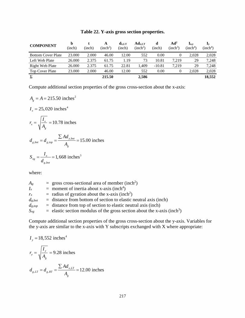
217
Table 22. Y-axis gross section properties.
COMPONENT b (inch)
t (inch)
A (inch2)
dx,LT (inch)
Adx,LT (inch2)
d (inch)
Ad2 (inch3)
Io,y (inch4)
Iy (inch4)
Bottom Cover Plate 23.000 2.000 46.00 12.00 552 0.00 0 2,028 2,028 Left Web Plate 26.000 2.375 61.75 1.19 73 10.81 7,219 29 7,248 Right Web Plate 26.000 2.375 61.75 22.81 1,409 -10.81 7,219 29 7,248 Top Cover Plate 23.000 2.000 46.00 12.00 552 0.00 0 2,028 2,028 Σ 215.50 2,586 18,552
Compute additional section properties of the gross cross-section about the x-axis:
2215.50 inchesgA A= =
425,020 inchesxI =
10.78 inchesxx
g
IrA
= =
,, , 15.00 inchesy bot
g bot g topg
Add d
A∑
= = =
3
,
1,668 inchesxxg
g bot
ISd
= =
where:
Ag = gross cross-sectional area of member (inch2) Ix = moment of inertia about x-axis (inch4) rx = radius of gyration about the x-axis (inch2) dg,bot = distance from bottom of section to elastic neutral axis (inch) dg,top = distance from top of section to elastic neutral axis (inch) Sxg = elastic section modulus of the gross section about the x-axis (inch3)
Compute additional section properties of the gross cross-section about the y-axis. Variables for the y-axis are similar to the x-axis with Y subscripts exchanged with X where appropriate:
418,552 inchesyI =
9.28 inchesyy
g
Ir
A= =
,, , 12.00 inchesx LT
g LT g RTg
Add d
A∑
= = =
218
2
,
1,546 inchesyyg
g LT
IS
d= =
where:
Iy = moment of inertia about y-axis (inch4) rx = radius of gyration about the y-axis (inch2) dg,LT = distance from left edge of section to elastic neutral axis (inch) dg,RT = distance from right edge of section to elastic neutral axis (inch)
B.2.6 Resistance Calculations
Compute the factored resistance for individual force effects including compression, tension, bending about both principal axes and shear along both principal axes. Prior to computing the resistances, check any general dimension and detailing requirements specific to noncomposite box-section members.
B.2.6.1 General Dimension and Detail Requirements
Article 6.7 contains general dimension and detailing requirements for various structural steel elements. For a noncomposite steel box truss member, Articles 6.7.3 and 6.7.4.4 apply. Article 6.7.3 specifies that the minimum plate thickness should not be less than 0.3125-inch, which is less than the minimum plate thickness in the cross section (2.000-inch cover plate). Article 6.7.4.4 covers diaphragm requirements, which are discussed later in Section B.2.9. The general truss detailing requirements of Article 6.7.4.5 also apply.
In addition to the requirements of Article 6.7, there are specific dimension and detailing requirements for compression, tension, flexure and shear. Those specific requirements are covered in the appropriate resistance calculation sections of this example.
B.2.6.2 Compression
The end post is subjected to axial compression. The factored compression resistance is calculated per Article 6.9.
B.2.6.2.1 Limiting Slenderness Ratio
Article 6.9.3 specifies the maximum slenderness ratio for primary compression members, which include truss end posts [C1]:
120Klr≤
Compute the slenderness ratio about each axis. For the x-axis, which is perpendicular to the plane of the truss:

219
( )( )0.750 813.9 56.7 120 OK
10.78x
Klr
= = ≤ ∴
where:
Kx = effective length factor specified in Article 4.6.2.5 = 0.750 for bolted end connections at both ends
lx = unbraced length for buckling about the x-axis in the direction of the y-axis, which is measured along the member from Joint L0 to Joint U1 = 813.9 inch
rx = radius of gyration about x-axis as calculated in Section B.2.5
For the y-axis, which is parallel to the plane of the truss:
( )( )0.750 673.6 54.4 120 OK
9.28y
Klr
= = ≤ ∴
where:
Ky = 0.750 for bolted end connections at both ends Ly = unbraced length for buckling about the y-axis in the direction of the x-axis, which is
measured along the member from Joint L0 to the bottom portal strut = 673.6 inch ry = radius of gyration about y-axis as calculated in Section B.2.5
B.2.6.2.2 Element Slenderness
As mentioned previously, the section is longitudinally unstiffened [C2]. Article 6.9.4.2.1 defines the nonslender width-to-thickness or slenderness limit for cross-section elements [C3]:
rbt≤ λ Eq. (6.9.4.2.1-1)
where:
b = element width as specified in Table 6.9.4.2.1-1 (inch) t = element thickness for plate element (inch) λr = width-to-thickness or slenderness ratio limit as specified in Table 6.9.4.2.1-1
Check the slenderness ratio of the cover plates, which qualify as other plates supported along two longitudinal edges in Table 6.9.4.2.1-1:
29,0001.09 1.09 26.2550r
y
EF
λ = = = Table 6.9.4.2.1-1
19.250 9.63 26.25 nonslender2.000 r
bt= = ≤ λ = ∴

220
where:
b = clear distance between webs for flanges of welded built-up box-sections = 24.000 – 2(2.375) = 19.250 inch
t = 2.000 inch
Repeat the calculation for the web plates:
26 10.95 26.25 nonslender2.375 r
bt= = ≤ λ = ∴
where:
b = clear distance between flanges for webs of welded built-up box-sections = 30.000 – 2(2.000) = 26.000 inch
t = 2.375 inch
Therefore, because the box is longitudinally unstiffened [C2] and all elements of the cross-section are nonslender [C3], Article 6.9.4.2.2 does not apply and the nominal compression resistance of the member is based only on Article 6.9.4.1.
B.2.6.2.3 Nominal Compressive Resistance
Article 6.9.4.1.1 defines the nominal compressive resistance for compression members with cross-sections composed only of nonslender longitudinally unstiffened elements. Compute the resistance:
2.25, then:o
e
PIfP
≤
0.658o
e
PP
n oP P
=
Eq. (6.9.4.1.1-1)
Otherwise:
0.877n oP P= Eq. (6.9.4.1.1-2)
where:
Po = nominal yield resistance (kips) Pe = elastic critical buckling resistance determined as specified in Article 6.9.4.1.2 for
flexural buckling (kips)
The cross-section is homogeneous, therefore Po is calculated as:
( )( )50 215.50 10,775 kipso y gP F A= = =

221
where:
Fy = specified minimum yield strength = 50 ksi Ag = gross cross-sectional area of the member (inch2) = 215.5 inch2
Per Article 6.9.4.1.1 and Table 6.9.4.1.1-1, the only applicable failure mode for closed sections is flexural buckling (FB). As a result, the elastic critical buckling resistance, Pe, is based only on flexural buckling. The limiting slenderness ratio, (Kl/rs), about the x- or y-axes producing the smallest value of Pe is 56.7 as calculated in Section B.2.6.2.1. The resulting flexural buckling resistance is [C4 and C5]:
( )( )
( )22
2 2
29,000215.50 19,220 kips
56.7e g
s
EP AKlr
ππ= = =
Eq. (6.9.4.1.2-1)
10,775 0.56 2.2519,220
o
e
PP
= = ≤ ∴ OK
10,77519,2200.658 10,775 8,521 kipsnP
= =
B.2.6.2.4 Factored Compression Resistance
The end post is subjected to axial compression. The factored compression resistance of the member is specified in Article 6.9.2.1 as [C6]:
r c nP P= φ Eq. (6.9.2.1-1)
where:
ϕc = resistance factor for axial compression, steel only, as specified in Article 6.5.4.2 = 0.95
Pn = nominal compressive resistance as specified in Article 6.9.4 for noncomposite members (kips)
( )( )0.95 8,521 8,095 kipsrc r c nP P P= = φ = =
B.2.6.3 Tension
The end post is not subjected to axial tension forces. However, for the purpose of this example, the factored tensile resistance will be computed in accordance with Article 6.8
B.2.6.3.1 Limiting Slenderness Ratio
222
Article 6.8.4 specifies the maximum slenderness ratio for primary tensile members, which include truss members:
200Klr≤
Per Section B.2.6.2.1, the controlling slenderness ratio is 56.7 for (Kl/r)x. Therefore:
56.7 200 OKx
Klr
= ≤ ∴
B.2.6.3.2 Factored Tensile Resistance
Article 6.8.2.1 defines the factored tensile resistance, Pr, as the lesser of:
r y ny y y gP P F A= φ = φ Eq. (6.8.2.1-1)
r u nu u u n pP P F A R U= φ = φ Eq. (6.8.2.1-2)
where:
ϕy = resistance factor for tension, yielding in gross section, as specified in Article 6.5.4.2 = 0.95
ϕu = resistance factor for tension, fracture in net section, as specified in Article 6.5.4.2 = 0.80
Pny = nominal tensile resistance for yielding on the gross section (kips) Pnu = nominal tensile resistance for fracture on the net section (kips) Fy = specified minimum yield strength = 50 ksi Ag = gross cross-sectional area of the member (inch2) Fu = tensile strength = 65 ksi An = net area of the member as specified in Article 6.8.3 (inch2) Rp = reduction factor for holes taken equal to 1.0 for bolt holes drilled full size or
subpunched and reamed to size U = reduction factor to account for shear lag as specified in Article 6.8.2.2
The critical section for net area is located at the connection of the member to the gusset plate at joint L0 (see Figure 39). The member web plates are connected to the gusset plates using seven one-inch diameter high-strength bolts in standard size holes. The cover plates are not bolted at the critical location. The end post at joint U1 does have bolts in the top cover plate as well as the web plates, but the bolts are staggered such that the net area at the critical U1 section is still larger than at L0. Additionally, because the cover plates are bolted, the reduction factor, U, is larger at joint U1. As a result, joint L0 controls for tensile resistance. The net area of the member per Article 6.8.3 is:
( ) ( ) ( )( )( ) 22 ( ) 212.50 2 7 1.125 2.375 178.09 inchesn g hole wA A n d t= − = − =
223
The shear lag factor, U, is calculated per Case 2 in Table 6.8.2.2-1 because the member is only connected through its web plates. Per Figure C6.8.2.2-1, one-half of the section should be treated as a channel shape to determine the connection eccentricity, x .
( )( )( ) ( )( )( )( )( ) ( )( )
2 11.500 2.000 6.250 26.000 2.375 1.1883.35 inches
2 11.500 2.000 26.000 2.375AdxA
+∑= = =
∑ +
3.351 1 0.91338.500
xUL
= − = − = Table 6.8.2.2-1
where:
x = connection eccentricity (in) L = length of connection = 38.500 inch
Calculate the controlling factored tensile resistance:
( )( )0.95 50 215.50 10,236 kipsry r y ny y y gP P P F A= = φ = φ = =
( )( )( )( )0.80 65 178.09 1.00 0.913 8,455 kipsru r u nu u u n pP P P F A R U= = φ = φ = =
The factored tensile resistance is controlled by fracture. For a complete design, block shear rupture of the bolted connection should be investigated per Article 6.13.4 to verify it does not control.
B.2.6.4 X-axis Flexure
The end post is subjected to flexure about the x-axis. Determine the factored flexural resistance per Article 6.12. The section is symmetric about the x-axis, therefore only one controlling value of compression and tension flange flexural resistance needs to be calculated. For flexure about the x-axis, the cover (flange) plates act as the flanges and the web plates act as the webs for Article 6.12.2.2.2.
B.2.6.4.1 Cross-Section Proportion Limits
Article 6.12.2.2.2b contains cross-section proportion limits for the application of Article 6.12.2.2 to noncomposite rectangular steel box-sections. For this example, the cross section is not stiffened longitudinally, thus check the appropriate limits for longitudinally unstiffened webs, longitudinally unstiffened flanges, and the outside width of the box [F1]:
26.000 10.9 150 OK2.375w
Dt
= = ≤ ∴ Eq. (6.12.2.2.2b-1)
19.250 9.6 90 OK2.000
fi
f
bt
= = ≤ ∴ Eq. (6.12.2.2.2b-3)
224
26.000 4.3 inches OK24 in e6 6
ch sfoDb = ≥ = = ∴ Eq. (6.12.2.2.2b-5)
where:
D = clear distance between flanges = 26.000 inch tw = thickness of the web = 2.375 inch tf = thickness of the flange under consideration = 2.000 inch bfi = clear width of flange under consideration between the webs = 19.250 inch bfo = distance from the outside to outside of the box-section webs = 24.000 inch
Article 6.12.2.2.2b states that flanges corresponding to the box section principal axis subjected to the larger bending moment should not be less than the thickness of the webs. For this example, the y-axis resists the larger bending moment and the ‘flange’ elements (web plates) are thicker than the ‘web’ elements (cover plates).
The commentary of Article 6.12.2.2.2b for flexure suggests a minimum plate thickness of ¾-inch for flange plates subjected to significant bending stresses; otherwise, a minimum thickness of ½-inch is recommended. These recommendations are intended to ensure robustness and resiliency of the member response; to facilitate handling; and to minimize distortion and possible cupping of the plates during welding. The minimum plate thickness of this cross-section is 2 inches, and exceeds both recommend limits.
B.2.6.4.2 Classification of Sections
Article 6.12.2.2.2c defines the web plastification factor for the compression flange, Rpc, the web load-shedding factor, Rb, and the compression-flange slenderness factor, Rf, based on web and compression flange slenderness values for longitudinally unstiffened compression flanges [F2].
The equations in Article 6.12.2.2.2c are based on section properties using the effective width of the compression flange, including the depth of web in compression in the elastic range, Dce, the depth of the web in compression at the plastic moment, Dcpe, the yield moment with respect to the compression flange, Myce, and the plastic moment, Mpe.
Prior to computing Sxce and Sxte, check if the effective span length of the member, Leff, is greater than five times the flange width between web plates, bfi, to prevent shear lag effects from reducing the effective flange area per Article 6.12.2.2.2g [F4]:
( )813.9 5 5 19.250 96.250 incheseff fiL inches b= > = =
where:
Leff = effective span length for bending about x-axis equal to the assumed simple span length between joints L0 and U1 = 813.9 inch
bfi = flange width between web plates = 19.250 inch
225
Therefore, the effective area of the longitudinally unstiffened compression flange, bet, and gross area of the tension flange are not limited due to shear lag effects at the strength limit state. Additionally, the member is not continuous or a cantilever, therefore Equations 6.12.2.2.2.g-2 and 3 do not apply.
Because the compression flange is nonslender [F3] and shear lag does not apply [F4], these variables are equal to those computed using the gross section in Section B.2.5. Additionally, because the member is symmetric about the x-axis, Dce is equal to Dcpe and the section modulus Sxte is the same as Sxce [F5]. Since Sxce ≤ Sxte, early nominal yielding in tension does not need to be considered per Article 6.12.2.2.2c; the equations in Section 3.2.2.3 are not necessary [F5A]. Compute Dce, Dcpe, Myce and Mpe as defined in Article 6.12.2.2.2c [F6]:
26.000 13.000 inches2 2ceDD = = =
( )( )50.0 1,6686,950 kip-ft
12yce yc xceM F S= = =
where:
Fyc = specified minimum yield strength of the compression flange (ksi) Sxce = effective elastic section modulus about the axis of bending to the compression flange
determined using the gross area of the tension flange and the effective width of the compression flange, be, calculated as specified in Article 6.9.4.2.2b with Fcr taken equal to Fyc. The compression flange and webs are nonslender (see the calculations below), therefore Sxce is equal to Sxg for the gross section.
Calculate the plastic moment, Mpe, using Case I in Table D6.1-2 for negative moment with the deck reinforcement parameters set to zero. The nomenclature assumes the bottom flange and lower portion of the web are in compression. Compute Dcpe and Mpe:
( )( )( )50.0 23.000 2.000 2,300 kipsc yc c cP F b t= = =
( )( )( )50.0 23.000 2.000 2,300 kipst yt t tP F b t= = =
( ) ( )( )( )( )2 50.0 26.000 2 2.375 6,175 kipsw yw wP F D t= = =
12
c t
w
P PDYP
− = +
Table D6.1-2 Case I
26.000 2,300 2,300 1 13.000 inches2 6,175
Y − = + =
26.000 13.000 13.000 inchescpe ceD D D Y= = − = − =
( )2c
ctd D Y= − +
226
( ) 2.00026.000 13.000 14.000 inches2cd = − + =
2t
ttd Y= +
2.00013.000 14.000 inches2td = + =
( ) [ ]22
2w
pe t t c cPM Y D Y Pd P dD = + − + + Table D6.1-2 Case I
( ) ( ) ( ) ( )( ) ( )( )2 26,175 13 2,300 14 2,300 14 /122 26
8,711 kips-ft
26 13peM = + + − +
=
where:
Pc = plastic force in the compression flange plate element (kips) Pt = plastic force in the tension flange plate element (kips) Pw = plastic force in both web plate elements (kips) D = clear distance between flanges (inch) Y = distance from top of web plate element to plastic neutral axis (inch) dc = distance from mid-thickness of compression flange plate element to plastic neutral
axis (inch) dt = distance from mid-thickness of tension flange plate element to plastic neutral axis
(inch)
To check the slenderness of the web, compute the limiting slenderness ratios per Article 6.12.2.2.2c and compare to the web slenderness [F17]:
13.000 29,0003.1 3.1 74.713.000 50
cepw rw
cpe yc
D ED F
λ = = = ≤ λ Eq. (6.12.2.2.2c-3)
29,0004.6 4.6 110.850rw
yc
EF
λ = = = Eq. (6.12.2.2.2c-6)
( )2 13.0002 10.9 2.375
cew pw
w
Dt
λ = = = < λ [F8] Eq. (6.12.2.2.2c-2)
where:
λpw = limiting slenderness ratio for a compact web λrw = limiting slenderness ratio for a noncompact web λw = web slenderness
227
Therefore the web is classified as compact per Equation 6.12.2.2.2c-1. Per Article 6.12.2.2.2c, determine Rpc and Rb [F9]:
8,711 1.2536,950
pepc
yce
MR
M= = = Eq. (6.12.2.2.2c-4)
1.0bR =
To check the slenderness of the compression flange, compute the limiting slenderness ratios per Article 6.12.2.2.2c [F10] and compare to the compression flange slenderness:
29,0001.09 1.09 26.350pf r
y
EF
λ = λ = = = Table 6.9.4.2.1-1
( )1.56 1.56 26.3 41.0rf pfλ = λ = = Eq. (6.12.2.2.2c-13)
19.25 9.62
fif pf
fc
bt
λ = = = < λ [F11] Eq. (6.12.2.2.2c-10)
where:
λpf = limiting slenderness ratio for a compact flange λrf = limiting slenderness ratio for a noncompact flange λf = compression flange slenderness
Therefore the compression flange is classified as compact per Equation 6.12.2.2.2c-9. Per Article 6.12.2.2.2c, determine Rf [F12]:
1.0fR = Eq. (6.12.2.2.2c-11)
B.2.6.4.3 Nominal Flexural Resistance Based on General Yielding, Compression Flange Local Buckling and Lateral Torsional Buckling
After checking the cross-section proportion limits and classifying the plate elements of the section, the nominal flexural resistance can be calculated per Article 6.12.2.2.2e. Compute the unbraced length limits, Lp and Lr, to determine the appropriate flexural resistance formula [F13]:
( )( ) ( )( ) 224.000 2.375 30.000 2.000 605.5 incheso fo w fA b t d t= − − = − − =
( ) ( ) ( ) ( )2 2 2 24.000 2.375 2 30.000 2.00045.2
2.000 2.375fo w s fm
f w
b t d tbt t t
− − − −∑ = + = + =
( )2244 605.54 32,442 inches
45.2o
m
AJ bt
= = =∑
Eq. (6.12.2.2.2e-3)

228
0.10p yyce
JAL ErM
= Eq. (6.12.2.2.2e-4)
( )( ) ( )( )( )
32,442 215.500.10 29,000 9.28 853 inches
6,950 12pL = =
0.60r yyr xce
JAL ErF S
= Eq. (6.12.2.2.2e-5)
( )0.5 0.5 50.0 25.0 ksiyr ycF F= = =
( )( ) ( )( )( )( )32,442 215.50
0.60 29,000 9.28 10,239 inches25.0 1,668rL = =
674b pL L= < [F14]
where:
J = St. Venant torsional constant of the gross cross-section (inch4) Ao = cross-sectional area enclosed by the mid-thickness of the walls of the box-section
member (inch2) bm = gross width of each plate of the box-section member taken between the mid-
thickness of the adjacent plates (inch) t = thickness of each plate of the box-section member (inch) Lp = limiting unbraced length to achieve nominal flexural resistance RfRbRcFycSxce under
uniform moment (inch) Lr = limiting unbraced length for calculation of the lateral torsional buckling resistance
(inch) Lb = unbraced length for x-axis bending = 674 inch ry = radius of gyration of the gross box-section about its minor principal axis (inch4) A = gross cross-sectional area of the box-section member (inch2) Fyr = compression flange stress at the onset of nominal yielding within the cross-section,
including residual stress effects, for moment applied about the axis of bending, taken as 0.5Fyc (ksi)
Therefore the nominal factored flexural resistance about the x-axis for the member is defined by Equation 6.12.2.2.2e-1 [F15]:
eb p fn yccM R R R M= Eq. (6.12.2.2.2e-1)
( )( )( )( )1.00 1.253 1.00 6,950 8,711 kip-ftnM = =
B.2.6.4.4 Factored Flexural Resistance
The end post is subjected to flexure about the x-axis. The factored flexural resistance of the member is specified in Article 6.12.1.2.1 as [F16]:
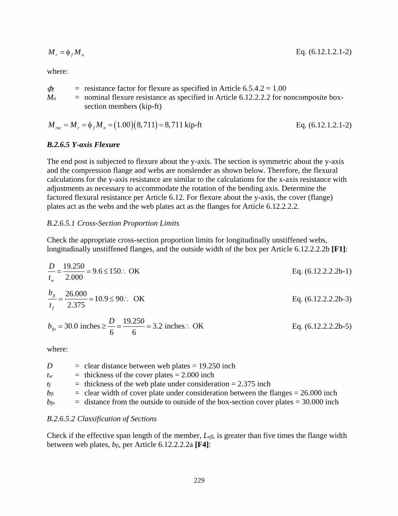
229
r f nM M= φ Eq. (6.12.1.2.1-2)
where:
ϕf = resistance factor for flexure as specified in Article 6.5.4.2 = 1.00 Mn = nominal flexure resistance as specified in Article 6.12.2.2.2 for noncomposite box-
section members (kip-ft)
( )( )1.00 8,711 8,711 kip-ftrxc r f nM M M= = φ = = Eq. (6.12.1.2.1-2)
B.2.6.5 Y-axis Flexure
The end post is subjected to flexure about the y-axis. The section is symmetric about the y-axis and the compression flange and webs are nonslender as shown below. Therefore, the flexural calculations for the y-axis resistance are similar to the calculations for the x-axis resistance with adjustments as necessary to accommodate the rotation of the bending axis. Determine the factored flexural resistance per Article 6.12. For flexure about the y-axis, the cover (flange) plates act as the webs and the web plates act as the flanges for Article 6.12.2.2.2.
B.2.6.5.1 Cross-Section Proportion Limits
Check the appropriate cross-section proportion limits for longitudinally unstiffened webs, longitudinally unstiffened flanges, and the outside width of the box per Article 6.12.2.2.2b [F1]:
19.250 9.6 150 OK2.000w
Dt
= = ≤ ∴ Eq. (6.12.2.2.2b-1)
26.000 10.9 90 OK2.375
fi
f
bt
= = ≤ ∴ Eq. (6.12.2.2.2b-3)
19.250 3.2 inches OK30.0 i6
nc e6
h sfoDb = ≥ = = ∴ Eq. (6.12.2.2.2b-5)
where:
D = clear distance between web plates = 19.250 inch tw = thickness of the cover plates = 2.000 inch tf = thickness of the web plate under consideration = 2.375 inch bfi = clear width of cover plate under consideration between the flanges = 26.000 inch bfo = distance from the outside to outside of the box-section cover plates = 30.000 inch
B.2.6.5.2 Classification of Sections
Check if the effective span length of the member, Leff, is greater than five times the flange width between web plates, bfi, per Article 6.12.2.2.2a [F4]:

230
( )140.3 inches 5 5 26.000 130.000 incheseff fiL b= > = =
where:
Leff = controlling effective span length for bending about y-axis equal to the assumed simple span between bottom portal strut and joint U1 = 140.3 inch
bfi = flange width between web plates = 26.000 inch
Therefore, the effective area of the longitudinally unstiffened compression flange, bet, and gross area of the tension flange are not limited due to shear lag effects at the strength limit state. Additionally, the member is not continuous or a cantilever, and the section is nonslender, therefore Equations 6.12.2.2.2.g-2 and 3 do not apply.
Similar to Section B.2.6.4.2 for flexure about the x-axis, compute Dce, Dcpe, Myce and Mpe for flexure about the y-axis as defined in Article 6.12.2.2.2c. Again, the section is longitudinally unstiffened [F2], nonslender [F3] and symmetric [F5] so early nominal yielding in tension does not need to be considered [F6].
19.250 9.625 inches2 2ceDD = = =
( )( )50.0 1,5466,442 kip-ft
12yce yc yceM F S= = =
Calculate the plastic moment, Mpe, using Case I in Table D6.1-2 for negative moment with the deck reinforcement parameters set to zero. The nomenclature assumes the bottom flange and lower portion of the web are in compression. For bending about the y-axis, the web plates are outside of the flange plates and extend to within ½-inch of the top and bottom faces of the box-section. Article D6.1 assumes the web and associated depth parameter, D, are measured between the flanges. Using the full depth of the web plates for D is acceptable if Y is measured from the top of the web plate and the calculations of Dcpe, dt and dc are adjusted as necessary to accommodate this deviation; thus D is equal to 23 inches instead of 19.25 inches for the following. Compute Dcpe and Mpe:
( )( )( )50.0 26.000 2.375 3,088 kipsc yc c cP F b t= = =
( )( )( )50.0 26.000 2.375 3,088 kipst yt t tP F b t= = =
( ) ( )( )( )( )2 50.0 23.000 2 2.000 4,600 kipsw yw wP F D t= = =
12
c t
w
P PDYP
− = +
Table D6.1-2 Case I
23.000 3,088 3,088 1 11.500 inches2 4,600
Y − = + =
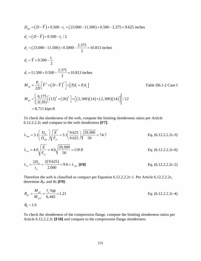
231
( ) ( )0.500 23.000 11.500 0.500 2.375 9.625 inchescpe cD D Y t= − + − = − + − =
( ) 0.500 / 2c cd D Y t= − + −
( ) 2.37523.000 11.500 0.5000 10.813 inches2cd = − + − =
0.5002t
ttd Y= + −
2.37511.500 0.500 10.813 inches2td = + − =
( ) [ ]22
2w
pe t t c cPM Y D Y Pd P dD = + − + + Table D6.1-2 Case I
( ) ( ) ( ) ( )( ) ( )( )2 26,175 13 26 2,300 14 2,300 14 /122 26
8,711 kips-ft
peM = + + +
=
To check the slenderness of the web, compute the limiting slenderness ratios per Article 6.12.2.2.2c and compare to the web slenderness [F7]:
9.625 29,0003.1 3.1 74.79.625 50
cepw
cpe yc
D ED F
λ = = = Eq. (6.12.2.2.2c-3)
29,0004.6 4.6 110.850rw
yc
EF
λ = = = Eq. (6.12.2.2.2c-6)
( )2 9.6252 9.6 2.000
cew pw
w
Dt
λ = = = < λ [F8] Eq. (6.12.2.2.2c-2)
Therefore the web is classified as compact per Equation 6.12.2.2.2c-1. Per Article 6.12.2.2.2c, determine Rpc and Rb [F9]:
7,768 1.216,442
pepc
yce
MR
M= = = Eq. (6.12.2.2.2c-4)
1.0bR =
To check the slenderness of the compression flange, compute the limiting slenderness ratios per Article 6.12.2.2.2c [F10] and compare to the compression flange slenderness:
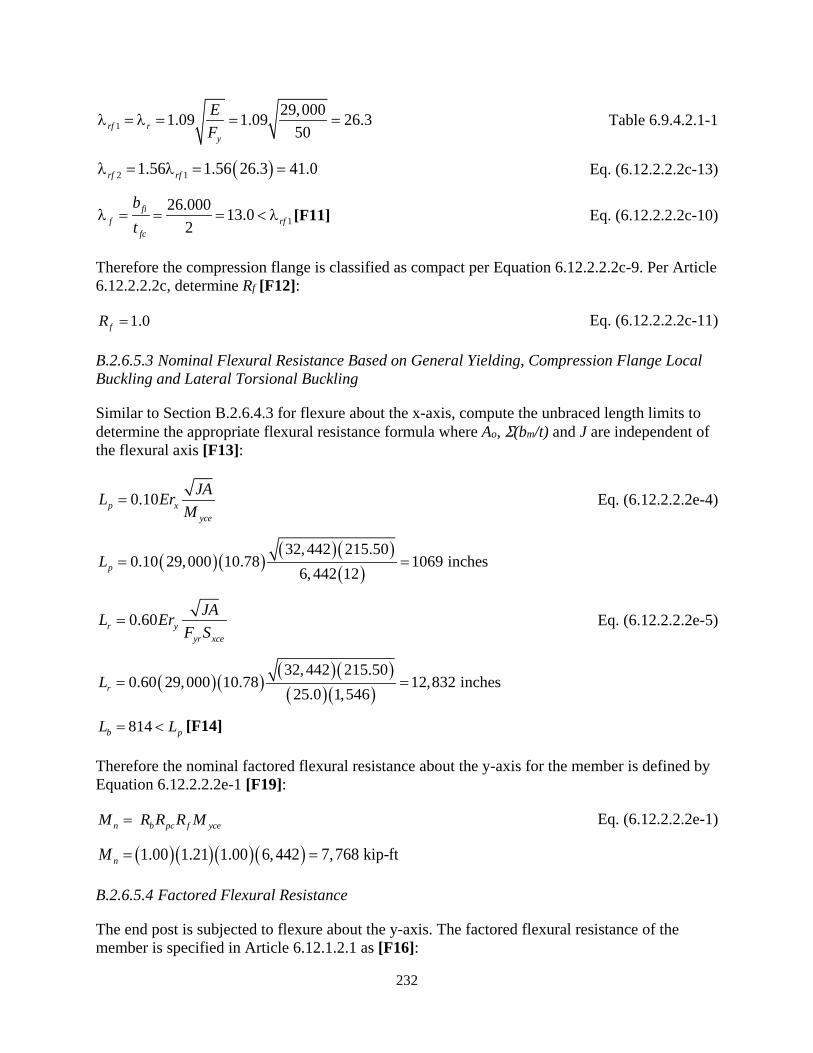
232
129,0001.09 1.09 26.3
50rf ry
EF
λ = λ = = = Table 6.9.4.2.1-1
( )2 11.56 1.56 26.3 41.0rf rfλ = λ = = Eq. (6.12.2.2.2c-13)
126.000 13.0
2fi
f rffc
bt
λ = = = < λ [F11] Eq. (6.12.2.2.2c-10)
Therefore the compression flange is classified as compact per Equation 6.12.2.2.2c-9. Per Article 6.12.2.2.2c, determine Rf [F12]:
1.0fR = Eq. (6.12.2.2.2c-11)
B.2.6.5.3 Nominal Flexural Resistance Based on General Yielding, Compression Flange Local Buckling and Lateral Torsional Buckling
Similar to Section B.2.6.4.3 for flexure about the x-axis, compute the unbraced length limits to determine the appropriate flexural resistance formula where Ao, Σ(bm/t) and J are independent of the flexural axis [F13]:
0.10pyce
xJAL Er
M= Eq. (6.12.2.2.2e-4)
( )( ) ( )( )( )
32,442 215.500.10 29,000 10.78 1069 inches
6,442 12pL = =
0.60r yyr xce
JAL ErF S
= Eq. (6.12.2.2.2e-5)
( )( ) ( )( )( )( )32,442 215.50
0.60 29,000 12,832 inches25.0 1,
10.78546rL = =
814b pL L= < [F14]
Therefore the nominal factored flexural resistance about the y-axis for the member is defined by Equation 6.12.2.2.2e-1 [F19]:
eb p fn yccM R R R M= Eq. (6.12.2.2.2e-1)
( )( )( )( )1.00 1.21 1.00 6,442 7,768 kip-ftnM = =
B.2.6.5.4 Factored Flexural Resistance
The end post is subjected to flexure about the y-axis. The factored flexural resistance of the member is specified in Article 6.12.1.2.1 as [F16]:

233
r f nM M= φ Eq. (6.12.1.2.1-1)
where:
ϕf = resistance factor for flexure as specified in Article 6.5.4.2 = 1.00 Mn = nominal flexure resistance as specified in Article 6.12.2.2.2 for noncomposite box-
section members (kip-ft)
( )( )1.00 7,768 7,768 kip - ftr r ny fcM MM == φ = = Eq. (6.12.1.2.1-2)
B.2.6.6 Y-axis Shear
The end post is subjected to shear in the direction of the y-axis, in the plane of the truss. Determine the factored shear resistance per Article 6.12.1.2.3. For shear along the y-axis, the web plates act as the web elements. Article 6.12.1.2.3a defines the factored shear resistance as:
r v nV V= φ Eq. (6.12.1.2.3a-2)
where:
ϕv = resistance factor for shear as specified in Article 6.5.4.2 = 1.00 Vn = nominal shear resistance as specified in Article 6.10.9 for noncomposite built-up
box-section members (kips)
Article 6.12.1.2.3a specifies that for box-section members subject to torsion, the factored shear in the web element is to be taken as the sum of the flexural and St. Venant torsional shears per Article 6.11.9. The St. Venant torsional shear in the plate elements will be calculated in Section B.2.7.1 for inclusion in the factored shear forces.
Article 6.10.9.1 repeats the factored resistance equation from Eq. 6.12.1.2.3a-2; defines unstiffened, transversely stiffened, and longitudinally stiffened webs; and specifies the articles concerning the design of transverse and longitudinal stiffeners. The end post is transversely stiffened only at diaphragm locations, which significantly exceeds the 3D maximum transverse stiffener spacing for stiffened webs. Therefore, the end post webs are unstiffened and the shear resistance is calculated as specified in Article 6.10.9.2
Calculate the nominal shear resistance, Vn, per Article 6.10.9.2. For the following calculations:
D = depth of the web plate = 26.000 inch measured between flanges for this cross-section where web plates extend past inside faces of the flange (cover) plates
tw = web thickness = 2.375 inch Fyw = specified minimum yield strength of the web (ksi) = 50 ksi C = ratio of the shear-buckling resistance to the shear yield strength determined by
Equations 6.10.9.3.2-4, 6.10.9.3.2-5 or 6.10.9.3.2-6 as applicable, with the shear-buckling coefficient, k, taken equal to 5.0
Vp = plastic shear force (kips) Vcr = shear-yielding or shear-buckling resistance (kips)

234
Compute the variable, C, per Article 6.10.9.3.2:
( )( )29,000 51.12 1.12 60.3
50.0yw
EkF
= =
( )( )29,000 51.40 1.40 75.4
50.0yw
EkF
= =
26.000 10.9 60.3 1.02.375w
D Ct
= = < ∴ = Eq. (6.10.9.3.2-4)
Compute Vn per Article 6.10.9.2:
( )( )( )0.58 0.58 50.0 26.000 2.375 1,791 kipsp yw wV F Dt= = = Eq. (6.10.9.2-2)
( )1.0 1,791 1,791 kipsn cr pV V CV= = = = Eq. (6.10.9.2-1)
Compute Vr per Article 6.12.1.2.3:
( )( )1.00 1,791 1,791 kips per web platery r v nV V V= = φ = = Eq. (6.12.1.2.3a-2)
B.2.6.7 X-axis Shear
The end post is subjected to shear in the direction of the x-axis, perpendicular to the plane of the truss. Similar to the web plates, the cover plates are unstiffened. Therefore, shear calculations for the x-axis shear resistance are similar to the y-axis procedure with adjustments as necessary to accommodate the rotation of the shear axis. For shear along the x-axis, the cover plates act as the web elements. Article 6.12.1.2.3a defines the factored shear resistance as:
r v nV V= φ Eq. (6.12.1.2.3a-2)
Calculate the nominal shear resistance, Vn, per Article 6.10.9.2:
where:
D = depth of the web = 19.250 inch measured along the cover plate between the inside faces of the flange (web) plates for the cross-section in this example
tw = web thickness = 2.000 inch
Compute the variable, C, per Article 6.10.9.3.2:
( )( )29,000 51.12 1.12 60.3
50.0yw
EkF
= = Article 6.10.9.3.2
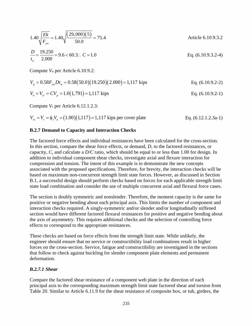
235
( )( )29,000 51.40 1.40 75.4
50.0yw
EkF
= = Article 6.10.9.3.2
19.250 9.6 60.3 1.02.000w
D Ct
= = < ∴ = Eq. (6.10.9.3.2-4)
Compute Vn per Article 6.10.9.2:
( )( )( )0.58 0.58 50.0 19.250 2.000 1,117 kipsp yw wV F Dt= = = Eq. (6.10.9.2-2)
( )1.0 1,791 1,117 kipsn cr pV V CV= = = = Eq. (6.10.9.2-1)
Compute Vr per Article 6.12.1.2.3:
( )( )1.00 1,117 1,117 kips per cover platerx r v nV V V= = φ = = Eq. (6.12.1.2.3a-1)
B.2.7 Demand to Capacity and Interaction Checks
The factored force effects and individual resistances have been calculated for the cross-section. In this section, compare the shear force effects, or demand, D, to the factored resistances, or capacity, C, and calculate a D/C ratio, which should be equal to or less than 1.00 for design. In addition to individual component shear checks, investigate axial and flexure interaction for compression and tension. The intent of this example is to demonstrate the new concepts associated with the proposed specifications. Therefore, for brevity, the interaction checks will be based on maximum non-concurrent strength limit state forces. However, as discussed in Section B.1, a successful design should perform checks based on forces for each applicable strength limit state load combination and consider the use of multiple concurrent axial and flexural force cases.
The section is doubly symmetric and nonslender. Therefore, the moment capacity is the same for positive or negative bending about each principal axis. This limits the number of component and interaction checks required. A singly-symmetric and/or slender and/or longitudinally stiffened section would have different factored flexural resistances for positive and negative bending about the axis of asymmetry. This requires additional checks and the selection of controlling force effects to correspond to the appropriate resistances.
These checks are based on force effects from the strength limit state. While unlikely, the engineer should ensure that no service or constructibility load combinations result in higher forces on the cross-section. Service, fatigue and constructibility are investigated in the sections that follow to check against buckling for slender component plate elements and permanent deformation.
B.2.7.1 Shear
Compare the factored shear resistance of a component web plate in the direction of each principal axis to the corresponding maximum strength limit state factored shear and torsion from Table 20. Similar to Article 6.11.9 for the shear resistance of composite box, or tub, girders, the
236
total shear in a web should be the sum of the flexural and St. Venant torsional shears when the section is subjected to torsion.
The shear in one web plate due to flexural shear is equal to the total shear on the cross-section, Vuy, divide by two web plates. The shear in the web plate due to St. Venant torsional shear is calculated based on Equation C6.11.1.1-1 for the St. Venant shear flow in the plate conservatively multiplied by the total width of the web plate.
Check web plate parallel to the y-axis for flexural shear, Vuy, and torsion, Tu:
( )( )( )
188 121.86 kips/in
2 2 605.5u
o
TfA
= = = Eq. (C6.11.1.1-1)
( )20 1.86 29.000 64 kips2 2uy
ui
VV fb= ± = ± =
64 1,791 kips OKui ryV kips V= < = ∴
( ) 64 0.04 1.001,791vy
DC = = <
where:
f = shear flow in web plate element due to St. Venant torsional shear (ksi) Ao = enclosed area within the box-section (inch2) Vui = factored shear force in an individual web plate (kips) bm = width of web plate measured between centerline of flanges (in)
These results show that the levels of shear acting along the y-axis combined with torsion have little effect on the cross-section of the member. As discussed previously, shear and torsional effects on truss members are often negligible and ignored. However, locations such as those subjected to frame action (i.e. floor beams rigidly and directly framed into truss verticals) may experience significant shear and torsional forces on adjacent members.
Similar to the y-axis, check the web plate parallel to the x-axis (cover plate) for flexural shear, Vux, and torsion, Tu:
( )( )( )
188 121.86 kips/in
2 2 605.5u
o
TfA
= = = Eq. (C6.11.1.1-1)
( )47 1.86 21.625 64 kips2 2ux
uiVV fb= ± = ± =
64 kips 1,117 kips OKui ryV V= < = ∴
( ) 64 0.06 1.001,117vy
DC = = <
237
Similar to the y-axis, the levels of shear acting on the x-axis have little effect on the cross-section of the member.
B.2.7.2 Combined Axial Compression and Flexure
Check the interaction of combined axial compression and flexure using the maximum non-concurrent strength limit state compression and biaxial bending effects from Table 20 per Article 6.9.2.2.1 [C7 and F17]. All cross-section elements are longitudinally unstiffened and defined as compact for flexure per Article 6.12.2.2.2c. Therefore, the interaction equations Eq. 6.9.2.2.1-1 and 6.9.2.2.1-2 apply. All ratios in the equations are positive. Per Article 6.9.2.2.1, the moments about the principal axes of the section are to include magnification. The moments in Table 20 are not amplified. Compute magnification factors per Article 4.5.3.2.2b using an approximate single-step adjustment method and apply to the total factored moment.
The end post is braced against sideway in both directions, therefore, only the magnification factor, 𝛿𝛿b, for members braced against sidesway is applicable. For each principal axis, calculate the magnification factor per Eq. 4.5.3.2.2b-3, where the factor, Cm, is dependent on the ratio of the end moments for the braced length. For this example, conservatively assume 1.0 for Cm. Calculate the magnification factor for flexure about the x-axis:
( )( )( )
( )( )22
2 2
29,000 25,02019,220 kips
0.75 813.9x
exx x
EIPK l
ππ= = = Eq. (4.5.3.2.2b-5)
( )
1.0 1.23 1.03,634111.0 19,220
mxbx
u
K ex
CPP
δ = = = ≥−−
φ
Eq. (4.5.3.2.2b-3)
where:
𝛿𝛿b = moment magnification for members braced against sideway per Article 4.5.3.2.2 Cm = modification factor based on member end moments, taken as 1.0 𝜙𝜙K = stiffness reduction factor = 1.0 for steel members Pe = Euler buckling load for axis under consideration computed per Eq. 4.5.3.2.2b-5
(kips) I = moment of inertia about axis under consideration (inch4) K = effective length factor in the plane of bending as specified in Article 4.6.2.5 lu = unsupported length of compression member in direction of buckling (in)
Repeat the calculations for the magnification factor for flexure about the y-axis:
( )( )( )
( )( )
2 2
2 2
29,000 18,55220,805 kips
0.75 673.6y
ey
y y
EIP
K l
π π= = = Eq. (4.5.3.2.2b-5)
238
( )
1.0 1.21 1.03,634111.0 20,805
myby
u
K ey
CPP
δ = = = ≥−−
φ
Eq. (4.5.3.2.2b-3)
Article 6.9.2.2.2 specifies reduction factors (Δ, Δx, and Δy) for Pr, Mrx, and Mry, respectively, if the cross-section is subjected to torsional shear stresses [C7A and F17A] that exceed 0.2𝜙𝜙TFcv as discussed below [C7B and F17B]. For this example, use the maximum torsion on the section (188 kip-ft) for the calculation of all reduction factors. For checking the 0.2𝜙𝜙TFcv limit, compute fve based on torsional shear only for web and cover plates per Section 3.3.2.2:
( )( )( ), ,
188 120.79 ksi
2 2 605.5 2.375ve web To w
TfA t
= = =
( )( )( ), ,
188 120.93 ksi
2 2 605.5 2.000ve f To w
TfA t
= = =
Compute Fcv for the web elements (flange elements for bending about y-axis). The web is unstiffened, therefore ks is equal to 5.34 per Article 6.11.8.2.2.
( )29,000 5.341.12 1.12 62.3
50.0s
yc
EkF
= =
26 10.9 62.32.375
fcf
fc
bt
λ = = = < Eq. (6.11.8.2.2-8)
Therefore, the nominal shear buckling resistance of the web is calculated as:
0.58 0.58(50) 29.0 ksicv ycF F= = = Eq. (6.11.8.2.2-5)
(1.00)(29.0) 29.0 ksiT cvFφ = =
, ,0.2 0.2(29.0) 5.8 ksi 0.79 ksiT cv ve web TF fφ = = > =
where:
𝜙𝜙T = resistance factor for torsion specified in Article 6.5.4.2 = 1.00 Fcv = nominal shear buckling resistance of the flange element under shear alone from
Equation 6.11.8.2.2-5, 6.11.8.2.2-6 or 6.11.8.2.2-7, as applicable ks = plate-buckling coefficient for uniform shear stress = 5.34 Fyc = yield strength of compression flange (ksi) 𝜆𝜆f = slenderness ratio for the compression flange bfc = compression-flange width between webs (inch) tfc = thickness of compression-flange (inch)

239
Therefore, torsional shear stresses do not apply [C7B and F17B] for the reduction factors ∆ or ∆y.
Next, compute 𝜙𝜙TFcv for the flange elements (flange elements for bending about x-axis). The flange is unstiffened, therefore ks is equal to 5.34 per Article 6.11.8.2.2.
( )29,000 5.341.12 1.12 62.3
50.0s
yc
EkF
= =
19.25 9.6 62.32.000
fcf
fc
bt
λ = = = < Eq. (6.11.8.2.2-8)
Therefore, the nominal shear buckling resistance of the web is calculated as:
0.58 0.58(50) 29.0 ksicv ycF F= = = Eq. (6.11.8.2.2-5)
(1.00)(29.0) 29.0 ksiT cvFφ = =
, ,0.2 0.2(29.0) 5.8 ksi 0.93 ksiT cv ve f TF fφ = = > =
Therefore, torsional shear stresses do not apply in [C7B and F17B] for the reduction factors ∆ and ∆x.
Additionally, if Pu/Pr exceeds 0.05 [C7E and F17E], which this member does for axial compression as shown later, the flexural shear stresses shall be included in fve for the calculation of the reduction factors. The flexural and torsional shear stresses, if applicable, should be concurrent with the factored force effect (Pu, Mux, and Muy) being considered.
Compute the flexural shear stresses in the web plates for the respective directions of applied shear using the factored shear and inside plate widths for inclusion in the calculation of the reduction factors because Pu/Pr exceeds 0.05:
( ) ( ), ,
2 16 20.16 ksi
26(2.375)uy
ve web Vw
Vf
Dt= = =
( ) ( ), ,
2 47 20.61 ksi
19.25(2.000)ux
ve f Vfi f
Vf
b t= = =
Compute the reduction factor for the web plates [C7G and F17G]:
2 2, , 0.161 1 1.00
27.6ve web V
yT cv
fF
∆ = − = − ≅ φ Eq. (6.9.2.2.2-1 and 2)
Thus, there is no reduction for flexure about the y-axis.
240
Compute the reduction factor for the flange plates [F21]:
2 2, , 0.611 1 1.00
27.6ve f V
xT cv
fF
∆ = − = − ≅ φ Eq. (6.9.2.2.2-1 and 2)
Therefore, there is no reduction for flexure about the x-axis. Additionally, because Δ is equal to minimum of ∆x and ∆y, there is not reduction for axial load as well [C18].
With the magnification and reduction factors calculated, interaction can be checked per Article 6.9.2.2.1 [C7H and F17H]:
( )3,634 0.45 0.20
Δ 1.00 8,095u
r
PP
= = >
( )( )( )
( )( )
8Δ 9 Δ Δ
1.23 610 1.21 1,1953,634 8 0.69 1.0 OK1.00 8,095 9 1.00 8,711 1.00 7,768
by uyu bx ux
r x rx y ry
MP MP M M
δδ+ +
= + + = < ∴
Eq. (6.9.2.2-2)
B.2.7.3 Combined Axial Tension and Flexure
The cross-section does not resist axial tension, therefore the interaction equations of Article 6.8.2.3.2 do not apply. However, per Article 6.12.2.2.2a, because the cross-section is subjected to flexure combined with axial compression, Article 6.8.2.3.3 for flanges subjected to tension under combined axial compression and flexure at connection locations with bolt holes needs to be investigated [C7H and F17I]. The only bolt holes in the critical location are for the connection of the web plates to the gusset plates. Therefore, Article 6.8.2.3.3 only apples to bending about the y-axis, or Muy. Check the tension flange holes for the web plates acting as flanges:
where:
Mr = factored tension rupture flexural resistance about the axis of bending under consideration as computed in Equation 6.8.2.3.3-2 (kip-in)
Pr = factored tensile yield resistance of the cross-section based on Equation 6.8.2.1-1 for members in axial compression (kips)
Anf = net area of the tension flange determined as specified in Article 6.8.3 (inch2) Agf = gross area of the tension flange (inch2) Fu = specified minimum tensile strength of the tension flange (ksi) Fyt = yield strength of the tension flange (ksi) St = elastic section modulus about the axis of bending to the tension flange taken as
Myt/Fyt (inch3)
Because the cross-section is noncomposite, symmetric about the axis of bending, and longitudinally unstiffened, St is equal to the previously compute Syg for the gross section.
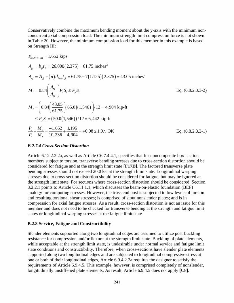
241
Conservatively combine the maximum bending moment about the y-axis with the minimum non-concurrent axial compression load. The minimum strength limit compression force is not shown in Table 20. However, the minimum compression load for this member in this example is based on Strength III:
, 1,652 kipsuc STR IIIP − =
( ) 226.000 2.375 61.75 inchesgf ft ftA b t= = =
( ) ( )( ) 261.75 7 1.125 2.375 43.05 inchesnf gf hole ftA A n d t= − = − =
0.84 nfr u t y t
gf
AM F S F S
A
= ≤
Eq. (6.8.2.3.3-2)
( )( )
( )( )
43.050.84 65.0 1,546 /12 4,904 kip-ft61.75
50.0 1,546 /12 6,442 kip-ft
r
y t
M
F S
= = ≤ = =
1,652 1,195 0.08 1.0 OK10,236 4,904
u u
r r
P MP M
−+ = + = + ≤ ∴ Eq. (6.8.2.3.3-1)
B.2.7.4 Cross-Section Distortion
Article 6.12.2.2.2a, as well as Article C6.7.4.4.1, specifies that for noncomposite box-section members subject to torsion, transverse bending stresses due to cross-section distortion should be considered for fatigue and at the strength limit state [F17D]. The factored transverse plate bending stresses should not exceed 20.0 ksi at the strength limit state. Longitudinal warping stresses due to cross-section distortion should be considered for fatigue, but may be ignored at the strength limit state. For sections where cross-section distortion should be considered, Section 3.2.2.1 points to Article C6.11.1.1, which discusses the beam-on-elastic foundation (BEF) analogy for computing stresses. However, the truss end post is subjected to low levels of torsion and resulting torsional shear stresses; is comprised of stout nonslender plates; and is in compression for axial fatigue stresses. As a result, cross-section distortion is not an issue for this member and does not need to be checked for transverse bending at the strength and fatigue limit states or longitudinal warping stresses at the fatigue limit state.
B.2.8 Service, Fatigue and Constructibility
Slender elements supported along two longitudinal edges are assumed to utilize post-buckling resistance for compression and/or flexure at the strength limit state. Buckling of plate elements, while acceptable at the strength limit state, is undesirable under normal service and fatigue limit state conditions and constructibility. Therefore, when cross-sections have slender plate elements supported along two longitudinal edges and are subjected to longitudinal compressive stress at one or both of their longitudinal edges, Article 6.9.4.2.2a requires the designer to satisfy the requirements of Article 6.9.4.5. This example, however, is comprised completely of nonslender, longitudinally unstiffened plate elements. As result, Article 6.9.4.5 does not apply [C8].

242
Article 6.12.2.2.2a for the flexural resistance of noncomposite box-section members requires that all members whether slender or nonslender, longitudinally stiffened or not, satisfy the requirements of Article 6.12.2.2.2f for similar reasons as stated above. The article requires cross-sections to be checked for web shear capacity during construction (Article 6.10.3.3) and special fatigue requirements for webs (Article 6.10.5.3) [F19]. These provisions must be checked for this example.
Additionally, Article 6.12.2.2.2f requires the use of Article 6.9.4.5 for a cross-section if it is a slender web section as defined in Article 6.12.2.2.2c; contains slender longitudinally stiffened panels per Article E6.1.2; or the slenderness, λf, of a longitudinally unstiffened compression flange exceeds the compact flange slenderness limit, λrf1, as defined in Article 6.12.2.2.2c. The cross-section in this example has a compact web, is longitudinally unstiffened and has a compact flange; therefore, Article 6.9.4.5 is not applicable [F21].
Check the web shear capacity during construction per Article 6.10.3.3 in each of the principal directions. Vuy is located in Table 20 and Vcr was determined in the sections calculating the shear resistance. In fact, the factored shear resistance of the plate element is equal to ϕvVcr. Article 6.10.3.3 requires:
u v crV V≤ φ Eq. (6.10.3.3-1)
Because the constructibility shears and torsion are less than the strength limit state shears and torsion; the shear resistances for this check and the strength limit state check are the same; and the strength limit state check showed that the resistance is much larger than the factored force; therefore, this provision is OK by inspection.
Check the special fatigue requirement for webs per Article 6.10.5.3, where:
u crV V≤ Eq. (6.10.5.3-1)
Similar to the previous check for Article 6.10.3.3, the applicable factored forces are less than the strength limit state forces and the shear resistance is the same (ϕv = 1.00); therefore, by inspection, this provision is OK.
Finally, Article 6.12.2.2.2f requires all noncomposite box-section members in flexure to satisfy the following requirement for Service II loads to control permanent deformations:
0.80f h yff R F≤ Eq. (6.12.2.2.2f-1)
where:
ff = flange stress due to overall flexure of the box-section member under Service II loads (ksi)
Fyf = specified minimum yield strength of the flange (ksi) Rh = hybrid factor determined as specified in Article 6.12.2.2.2c

243
Compute the flange stresses for bending about the x and y-axes using the Service II moments in Table 20. Also, because shear lag per Article 6.12.2.2.2g does not apply, use the gross section properties in Section B.2.5:
467(12) 3.4 ksi1,668
uxfx
xg
MfS
= = =
381(12) 3.0 ksi1,546
uyfy
yg
Mf
S= = =
Compute the limiting stress and compare the limit to the maximum value of ff (x-axis). Rh and Fyf are the same about both axes.
0.80 0.80(1.0)(50) 40.0 ksi 3.4 ksi OKh yfR F = = > ∴
B.2.9 Diaphragm Requirements
Article 6.7.4.4.1 requires that diaphragms be connected to the webs and flanges of the box-section and designed for any torsional forces applied to or resisted by the cross-section at the location of the diaphragm [C9 and F22]. Article 6.7.4.4.3 requires internal diaphragms at connection locations and other points of concentrated loads specifying minimum recommended access hole dimensions. Article 6.7.4.4.3 also limits the spacing diaphragms to 40 feet for members subjected to a maximum factored torsional shear stress exceeding 0.2φTFcv as defined in Article 6.9.2.2.2. Article 6.7.4.4.3 also discuss requirements for cross-frames used as diaphragms.
The end post is detailed with diaphragms at the member ends (Joints L0 and U1) and at the bottom portal strut location. The maximum diaphragm spacing in the end post is 56.13 feet, which exceeds the 40 feet limit specified in Article 6.7.4.4.3. Access holes are sized in accordance with Article 6.7.4.4.3.
B.2.10 Adjustments for HSS Members
Example 1 is based on a welded built-up rectangular box. The provisions presented in this report can also be applied to rectangular or square HSS members, hot or cold-formed. Standard HSS members may contain nonslender elements as in this example or slender elements – requiring the use of an effective compression width per Article 6.9.4.2.2b. Longitudinally stiffening the compression flange of an HSS member is impractical due to the internal dimensions and sequence of fabrication. This eliminates the applicability of Appendix E6 and Article 6.12.2.2.2d.
HSS members require modifications to the dimensional variables for use with these provisions as described in Article 6.12.1.2.4. The flange or web thickness for an HSS member produced according to ASTM A1085 uses the nominal wall thickness; however, the design thickness for all other HSS members is 0.93 times the nominal wall thickness. Additionally, the flange dimension measured between the inside face of the webs for welded boxes is equal to the distance between walls minus the inside corner radius on each side for square and rectangular

244
HSS. The outside dimension minus three times the appropriate design wall thickness specified in Article 6.12.1.2.4 should be used if the corner radius is not known. The web dimension, measured between flanges for weld boxes, is adjusted in the same manner.
The following is a list of modifications for HSS members in the relevant articles of this report, which may not be all-inclusive:
• Diaphragms: o Article 6.7.4.4.2: Diaphragms are only suggested at the ends of members and the
use and size of access holes is limited.
• Axial Tension Resistance: o Article 6.8.2.2: The calculation of the shear lag factor, U, varies in Table 6.8.2.2-1
using Case 6.
• Axial Compression Resistance:
o Article 6.9.4.2.1: The element width, b, and slenderness ratio limit, 𝜆𝜆r, in varies in Table 6.9.4.2.1-1. The slenderness ratio limit is increased compared to welded boxes but varies between hot and cold-formed HSS.
o Article 6.9.4.2.2a: The calculation of effective cross-sectional area, Aeff, uses Eq. 6.9.4.2.2a-3 to include fillet areas in total area.
o Article 6.9.4.2.2b: The imperfection adjustment factors, c1, c2 and c3, used to calculate the effective width, be, of a slender element varies in Table 6.9.4.2.2b-1. The coefficients increase the effective width compared to welded boxes but varies between hot and cold-formed HSS.
• Flexural Resistance: o Article 6.12.2.2.2b: The flange width, web depth and thickness are adjusted for
the cross-section proportion limits. o Article 6.12.2.2.2c: The depth of the web in compression in the elastic state, Dce,
the depth of the web in compression at the plastic moment, Dcpe, the inside width of the box for checking flange slenderness, bfi, and the plate thickness, t, are adjusted.
o Article 6.12.2.2.2e: The St. Venant torsional constant, J, and gross cross-sectional area, A, can be determined from reference documents such as AISC (2016).
o Article 6.12.2.2.2g: The inside width of the box-section, bfi, for shear lag effects due to span length is adjusted.
• Shear Resistance: o Article 6.12.1.2.3b: The design web depth and wall thickness are adjusted.
• Combined Axial Flexure Resistance:

245
o Article 6.9.2.2.2: The web depth and thickness dimensions are adjusted for calculating the nominal shear buckling resistance of the cross-section element under consideration.
• Service, Fatigue and Constructibility: o Article 6.9.4.5: No changes specified, however, the appropriate plate width and
thickness dimensions should be used.
• Solid Web Arches: o Article 6.14.4: No changes specified, however, the appropriate plate width and
thickness dimensions should be used.
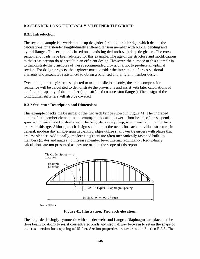
246
B.3 SLENDER LONGITUDINALLY STIFFENED TIE GIRDER
B.3.1 Introduction
The second example is a welded built-up tie girder for a tied-arch bridge, which details the calculations for a slender longitudinally stiffened tension member with biaxial bending and hybrid flanges. This example is based on an existing tied-arch with deep tie girders. The cross-section and loads have been adjusted for this example. The age of the structure and modifications to the cross-section do not result in an efficient design. However, the purpose of this example is to demonstrate the principles of these recommended provisions, not to produce an optimal section. For design projects, the engineer must consider the interaction of cross-sectional elements and associated resistances to obtain a balanced and efficient member design.
Even though the tie girder is subjected to axial tensile loads only, the axial compression resistance will be calculated to demonstrate the provisions and assist with later calculations of the flexural capacity of the member (e.g., stiffened compression flanges). The design of the longitudinal stiffeners will also be covered.
B.3.2 Structure Description and Dimensions
This example checks the tie girder of the tied arch bridge shown in Figure 41. The unbraced length of the member element in this example is located between floor beams of the suspended span, which are spaced 50-feet apart. The tie girder is very deep, which was common for tied-arches of this age. Although each design should meet the needs for each individual structure, in general, modern day simple-span tied-arch bridges utilize shallower tie girders with plates that are less slender. Additionally, modern tie girders are often mechanically-fastened built-up members (plates and angles) to increase member level internal redundancy. Redundancy calculations are not presented as they are outside the scope of this report.
Source: FHWA
Figure 41. Illustration. Tied arch elevation.
The tie girder is singly-symmetric with slender webs and flanges. Diaphragms are placed at the floor beam locations to resist concentrated loads and also halfway between to retain the shape of the cross-section for a spacing of 25 feet. Section properties are described in Section B.3.5. The
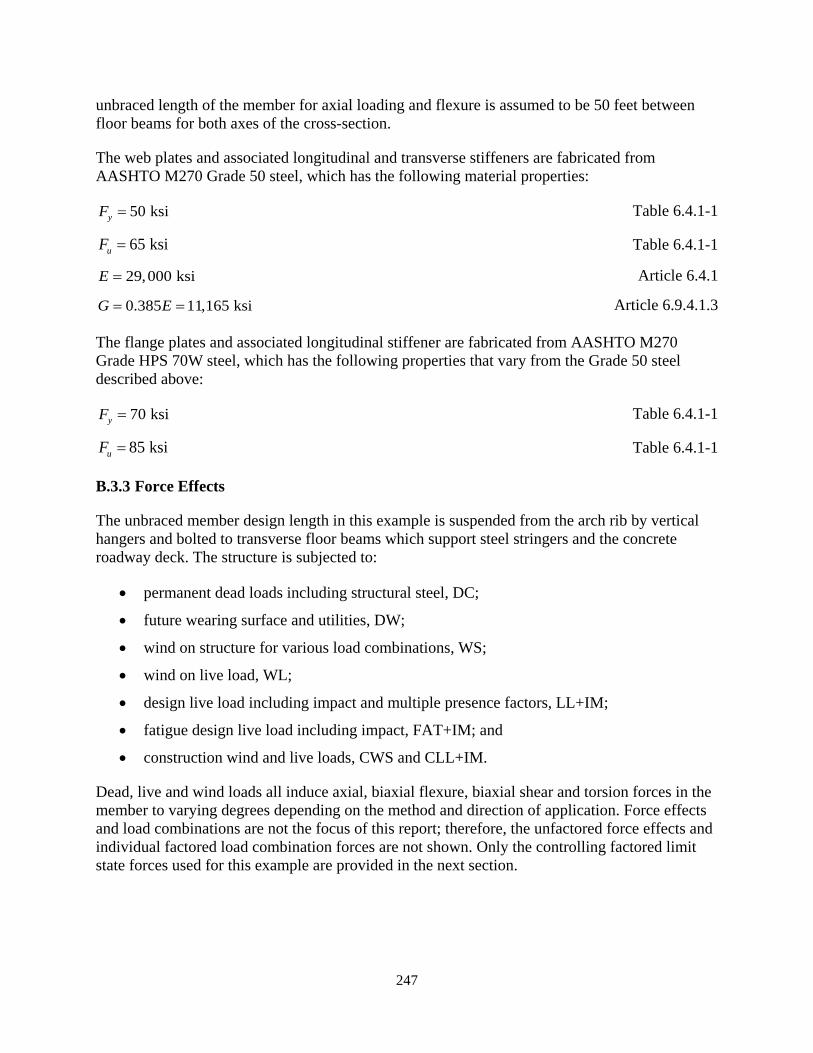
247
unbraced length of the member for axial loading and flexure is assumed to be 50 feet between floor beams for both axes of the cross-section.
The web plates and associated longitudinal and transverse stiffeners are fabricated from AASHTO M270 Grade 50 steel, which has the following material properties:
50 ksiyF = Table 6.4.1-1
65 ksiuF = Table 6.4.1-1
29,000 ksiE = Article 6.4.1
0.385 11,165 ksiG E= = Article 6.9.4.1.3
The flange plates and associated longitudinal stiffener are fabricated from AASHTO M270 Grade HPS 70W steel, which has the following properties that vary from the Grade 50 steel described above:
70 ksiyF = Table 6.4.1-1
85 ksiuF = Table 6.4.1-1
B.3.3 Force Effects
The unbraced member design length in this example is suspended from the arch rib by vertical hangers and bolted to transverse floor beams which support steel stringers and the concrete roadway deck. The structure is subjected to:
• permanent dead loads including structural steel, DC;
• future wearing surface and utilities, DW;
• wind on structure for various load combinations, WS;
• wind on live load, WL;
• design live load including impact and multiple presence factors, LL+IM;
• fatigue design live load including impact, FAT+IM; and
• construction wind and live loads, CWS and CLL+IM.
Dead, live and wind loads all induce axial, biaxial flexure, biaxial shear and torsion forces in the member to varying degrees depending on the method and direction of application. Force effects and load combinations are not the focus of this report; therefore, the unfactored force effects and individual factored load combination forces are not shown. Only the controlling factored limit state forces used for this example are provided in the next section.

248
B.3.4 Load Modifiers, Limit States and Factored Loads
From the bridge analysis, it was determined that the controlling factored forces in the tie girder are located at the floor beams and midway between. Thus, the combined axial and flexural checks should be based on the combination of maximum flexural forces in each bending direction, independent of their location along their controlling unbraced length. This ensures that the maximum combination of force effects along the length of the member is covered as discussed in the commentary for Article 6.9.2.2.1. Per Article 1.3, the strength limit state load modifier is 1.10 for maximum load factor values and 0.91 for minimum load factor values as calculated below. The load modifier is 1.0 for the other limit states.
1.00 for conventional designDη = Article 1.3.3
1.05 for nonredundant membersRη = Article 1.3.4
1.05 for critical or essential bridgesIη = Article 1.3.5
(1.0)(1.05)(1.05) 1.10 0.95i D R Iη = η η η = = ≥ Eq. (1.3.2.1-2)
1 1 0.91 1.01.10i
D R I
η = = = ≤η η η
Eq. (1.3.2.1-3)
Load combinations are performed for the relevant combinations discussed in Article 3.4.1 using Tables 3.4.1-1 and 3.4.1-2 with load modifiers as appropriate. DL + Fatigue I is the permanent dead load plus Fatigue-I factored live load. The construction load combinations for this example are the strength limit states with modified load factors relevant to the structure in accordance with Article 3.4.2.1. For this demonstration, the example loads are presented in Table 23.
Table 23. Maximum cross-section limit state forces.
LIMIT STATE Axial
P (kips)
Shear Vy
(kips)
Shear Vx
(kips)
Torsion T
(kip-ft)
Moment My
(kip-ft)
Moment Mx
(kip-ft) Strength (+) 5,275 518 61 1,312 2,288 30,098 Strength (-) 2,037 -423 -67 -1,076 -3,010 -29,161 Service II (+) 3,580 360 25 890 1,045 21,000 Service II (-) 2,900 -291 -30 -680 -1,370 -19,900 DL + Fatigue I (+) 3,040 207 11 231 870 15,500 DL + Fatigue I (-) 2,900 -206 -22 -31 -975 -9,250 Constructibility (+) 4,270 301 29 425 1,405 17,920 Constructibility (-) 2,489 -132 -36 -31 -1,607 -5,950
As with Example 1, the axial load, P, is in units of kips and negative for compression and positive for tension. Shears, Vx and Vy, are in units of kips with sign convention according to the axes shown in Figure 42. Torsion, T, is in units of kip-ft. Bending moments, Mx and My are in units of kip-ft with sign convention according to the axes shown in Figure 42.
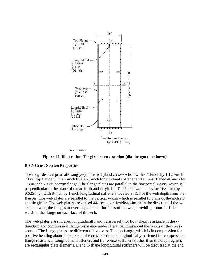
249
Source: FHWA
Figure 42. Illustration. Tie girder cross section (diaphragm not shown).
B.3.5 Gross Section Properties
The tie girder is a prismatic singly-symmetric hybrid cross-section with a 48-inch by 1.125-inch 70 ksi top flange with a 7-inch by 0.875-inch longitudinal stiffener and an unstiffened 48-inch by 1.500-inch 70 ksi bottom flange. The flange plates are parallel to the horizontal x-axis, which is perpendicular to the plane of the arch rib and tie girder. The 50 ksi web plates are 168-inch by 0.625-inch with 8-inch by 1-inch longitudinal stiffeners located at D/3 of the web depth from the flanges. The web plates are parallel to the vertical y-axis which is parallel to plane of the arch rib and tie girder. The web plates are spaced 44-inch apart inside-to-inside in the direction of the x-axis allowing the flanges to overhang the exterior faces of the web, providing room for fillet welds to the flange on each face of the web.
The web plates are stiffened longitudinally and transversely for both shear resistance in the y-direction and compression flange resistance under lateral bending about the y-axis of the cross-section. The flange plates are different thicknesses. The top flange, which is in compression for positive bending about the x-axis of the cross-section, is longitudinally stiffened for compression flange resistance. Longitudinal stiffeners and transverse stiffeners ( other than the diaphragms), are rectangular plate elements. L and T-shape longitudinal stiffeners will be discussed at the end
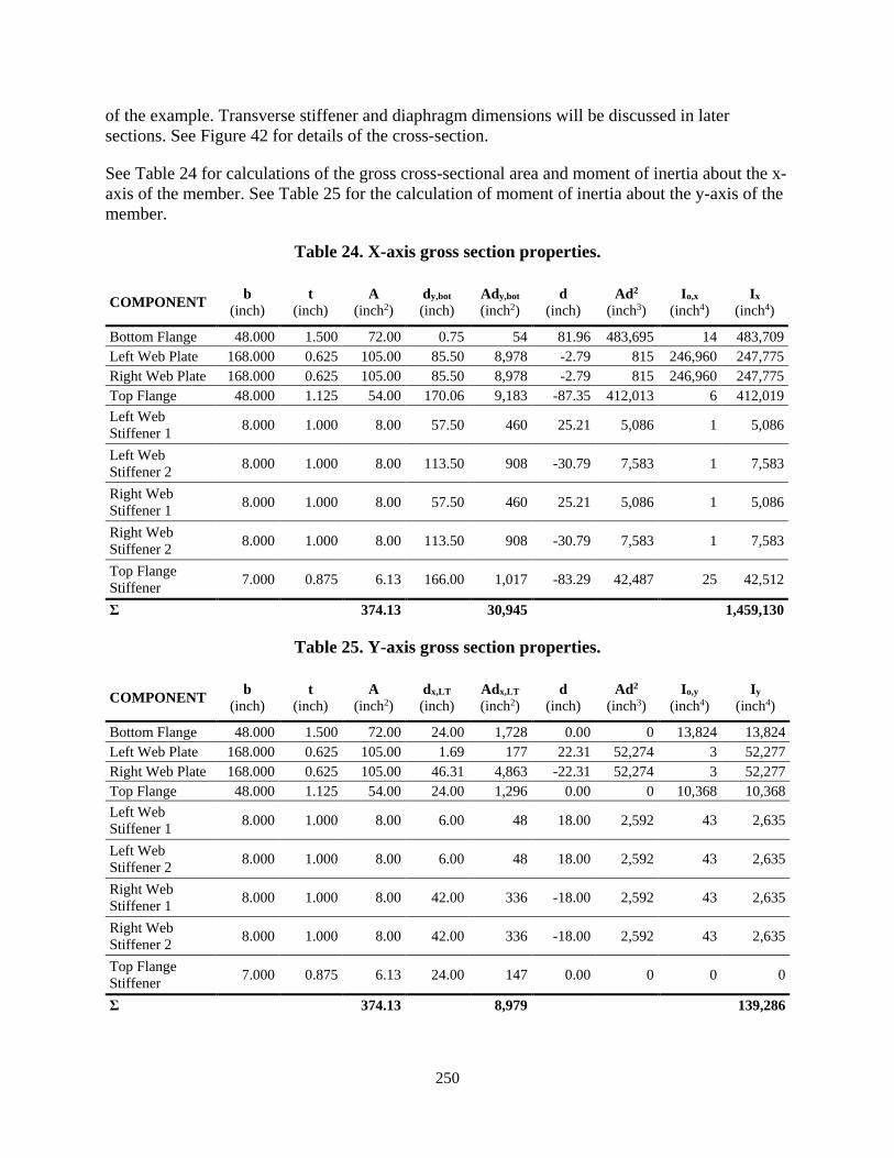
250
of the example. Transverse stiffener and diaphragm dimensions will be discussed in later sections. See Figure 42 for details of the cross-section.
See Table 24 for calculations of the gross cross-sectional area and moment of inertia about the x-axis of the member. See Table 25 for the calculation of moment of inertia about the y-axis of the member.
Table 24. X-axis gross section properties.
COMPONENT b (inch)
t (inch)
A (inch2)
dy,bot (inch)
Ady,bot (inch2)
d (inch)
Ad2 (inch3)
Io,x (inch4)
Ix (inch4)
Bottom Flange 48.000 1.500 72.00 0.75 54 81.96 483,695 14 483,709 Left Web Plate 168.000 0.625 105.00 85.50 8,978 -2.79 815 246,960 247,775 Right Web Plate 168.000 0.625 105.00 85.50 8,978 -2.79 815 246,960 247,775 Top Flange 48.000 1.125 54.00 170.06 9,183 -87.35 412,013 6 412,019 Left Web Stiffener 1 8.000 1.000 8.00 57.50 460 25.21 5,086 1 5,086
Left Web Stiffener 2 8.000 1.000 8.00 113.50 908 -30.79 7,583 1 7,583
Right Web Stiffener 1 8.000 1.000 8.00 57.50 460 25.21 5,086 1 5,086
Right Web Stiffener 2 8.000 1.000 8.00 113.50 908 -30.79 7,583 1 7,583
Top Flange Stiffener 7.000 0.875 6.13 166.00 1,017 -83.29 42,487 25 42,512
Σ 374.13 30,945 1,459,130
Table 25. Y-axis gross section properties.
COMPONENT b (inch)
t (inch)
A (inch2)
dx,LT (inch)
Adx,LT (inch2)
d (inch)
Ad2 (inch3)
Io,y (inch4)
Iy (inch4)
Bottom Flange 48.000 1.500 72.00 24.00 1,728 0.00 0 13,824 13,824 Left Web Plate 168.000 0.625 105.00 1.69 177 22.31 52,274 3 52,277 Right Web Plate 168.000 0.625 105.00 46.31 4,863 -22.31 52,274 3 52,277 Top Flange 48.000 1.125 54.00 24.00 1,296 0.00 0 10,368 10,368 Left Web Stiffener 1 8.000 1.000 8.00 6.00 48 18.00 2,592 43 2,635
Left Web Stiffener 2 8.000 1.000 8.00 6.00 48 18.00 2,592 43 2,635
Right Web Stiffener 1 8.000 1.000 8.00 42.00 336 -18.00 2,592 43 2,635
Right Web Stiffener 2 8.000 1.000 8.00 42.00 336 -18.00 2,592 43 2,635
Top Flange Stiffener 7.000 0.875 6.13 24.00 147 0.00 0 0 0
Σ 374.13 8,979 139,286

251
Compute additional section properties of the gross cross-section about the x-axis. The cross-section is asymmetric about the x-axis, therefore the neutral axis depth and section modulus to the top and bottom flanges must be computed separately.
2374.13 inchgA A= =
41, 459,130 inchxI =
62.45 inchesxx
g
IrA
= =
,, 82.71 inchesy bot
g botg
Add
A= =∑
3,
,
17,641 inchxxg bot
g bot
ISd
= =
168 inchesD =
, , 1.500 168 1.125 170.625 inchess f bot f topD t D t= + + = + + =
, , 87.91 inchesg top s g botd D d= − =
3,
,
16,598 inchxxg top
g top
ISd
= =
where:
Ag = gross cross-sectional area of member (inch2) Ix = moment of inertia about x-axis (inch4) rx = radius of gyration about the x-axis (inch) dg,bot = distance from bottom of section to elastic neutral axis (inch) Sxg,bot = elastic section modulus of the gross section about the x-axis to the bottom flange
(inch3) D = depth of web plate (inch) Ds = depth of total steel section (inch) dg,top = distance from top of section to elastic neutral axis (inch) Sxg,top = elastic section modulus of the gross section about the x-axis to the top flange (inch3)
Compute additional section properties of the gross cross-section about the y-axis. Variables for the y-axis are similar to the x-axis with Y subscripts exchanged with X where appropriate. The cross-section is symmetric about the y-axis, therefore the distance to the neutral axis and section modulus are the same to the each extreme fiber (left or right edge of flanges).
4139,286 inchyI =
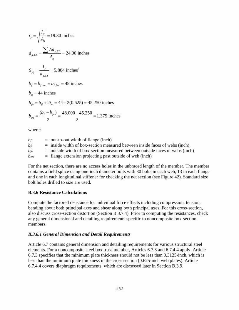
252
19.30 inchesyy
g
Ir
A= =
,, 24.00 inchesx LT
g LTg
Add
A= =∑
3
,
5,804 inchesyyg
g LT
IS
d= =
, , 48 inchesf f top f botb b b= = =
44 inchesfib =
2 44 2(0.625) 45.250 inchesfo fi wb b t= + = + =
( ) 48.000 45.250 1.375 inches2 2
f foext
b bb
− −= = =
where:
bf = out-to-out width of flange (inch) bfi = inside width of box-section measured between inside faces of webs (inch) bfo = outside width of box-section measured between outside faces of webs (inch) bext = flange extension projecting past outside of web (inch)
For the net section, there are no access holes in the unbraced length of the member. The member contains a field splice using one-inch diameter bolts with 30 bolts in each web, 13 in each flange and one in each longitudinal stiffener for checking the net section (see Figure 42). Standard size bolt holes drilled to size are used.
B.3.6 Resistance Calculations
Compute the factored resistance for individual force effects including compression, tension, bending about both principal axes and shear along both principal axes. For this cross-section, also discuss cross-section distortion (Section B.3.7.4). Prior to computing the resistances, check any general dimensional and detailing requirements specific to noncomposite box-section members.
B.3.6.1 General Dimension and Detail Requirements
Article 6.7 contains general dimension and detailing requirements for various structural steel elements. For a noncomposite steel box truss member, Articles 6.7.3 and 6.7.4.4 apply. Article 6.7.3 specifies that the minimum plate thickness should not be less than 0.3125-inch, which is less than the minimum plate thickness in the cross section (0.625-inch web plates). Article 6.7.4.4 covers diaphragm requirements, which are discussed later in Section B.3.9.
253
In addition to the requirements of Article 6.7, there are specific dimensional and detailing requirements for compression, tension, flexure and shear. Those specific requirements are covered in the appropriate resistance calculation sections of this example.
B.3.6.2 Compression
The tie girder is not subjected to axial compression. However, the axial compression resistance will be calculated to demonstrate the provisions and assist with the calculation of the flexural resistance when the compression flange is longitudinally stiffened. The factored compression resistance is calculated per Article 6.9.
B.3.6.2.1 Limiting Slenderness Ratio
Article 6.9.3 specifies the maximum slenderness ratio for primary compression members [C1]:
120Klr
≤
Compute the slenderness ratio about each axis. For the x-axis, which is perpendicular to the plane of the arch rib and tie girder:
1.0(600) 9.6 120 OK62.45x
Klr
= = < ∴
where:
Kx = effective length factor specified in Article 4.6.2.5, assumed to be 1.0 using the conservative assumption of pinned ends at the floor beam locations
lx = unbraced length for buckling about the x-axis in the direction of the y-axis, which is measured along the member between floor beams = 600.0 inches
rx = radius of gyration about x-axis as calculated in Section B.3.5 = 62.45 inch
For the y-axis, which is parallel to the plane of the arch rib and tie girder:
1.0(600) 31.1 120 OK19.30y
Klr
= = < ∴
where:
Ky = 1.0 similar to Kx
ly = unbraced length for buckling about the y-axis in the direction of the x-axis, which is measured along the member between floor beams = 600.0 inches
ry = radius of gyration about y-axis as calculated in Section B.3.5 = 19.30 inch
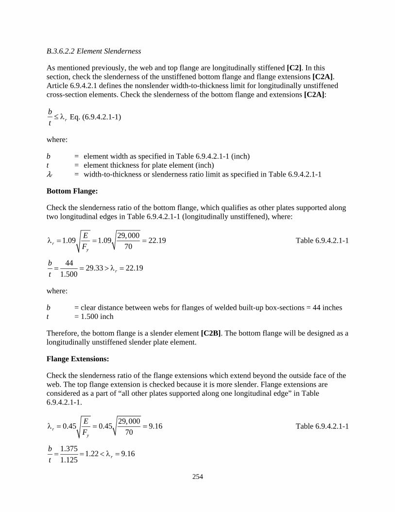
254
B.3.6.2.2 Element Slenderness
As mentioned previously, the web and top flange are longitudinally stiffened [C2]. In this section, check the slenderness of the unstiffened bottom flange and flange extensions [C2A]. Article 6.9.4.2.1 defines the nonslender width-to-thickness limit for longitudinally unstiffened cross-section elements. Check the slenderness of the bottom flange and extensions [C2A]:
rbt≤ λ Eq. (6.9.4.2.1-1)
where:
b = element width as specified in Table 6.9.4.2.1-1 (inch) t = element thickness for plate element (inch) λr = width-to-thickness or slenderness ratio limit as specified in Table 6.9.4.2.1-1
Bottom Flange:
Check the slenderness ratio of the bottom flange, which qualifies as other plates supported along two longitudinal edges in Table 6.9.4.2.1-1 (longitudinally unstiffened), where:
29,0001.09 1.09 22.1970r
y
EF
λ = = = Table 6.9.4.2.1-1
44 29.33 22.191.500 r
bt= = > λ =
where:
b = clear distance between webs for flanges of welded built-up box-sections = 44 inches t = 1.500 inch
Therefore, the bottom flange is a slender element [C2B]. The bottom flange will be designed as a longitudinally unstiffened slender plate element.
Flange Extensions:
Check the slenderness ratio of the flange extensions which extend beyond the outside face of the web. The top flange extension is checked because it is more slender. Flange extensions are considered as a part of “all other plates supported along one longitudinal edge” in Table 6.9.4.2.1-1.
29,0000.45 0.45 9.1670r
y
EF
λ = = = Table 6.9.4.2.1-1
1.375 1.22 9.161.125 r
bt= = < λ =
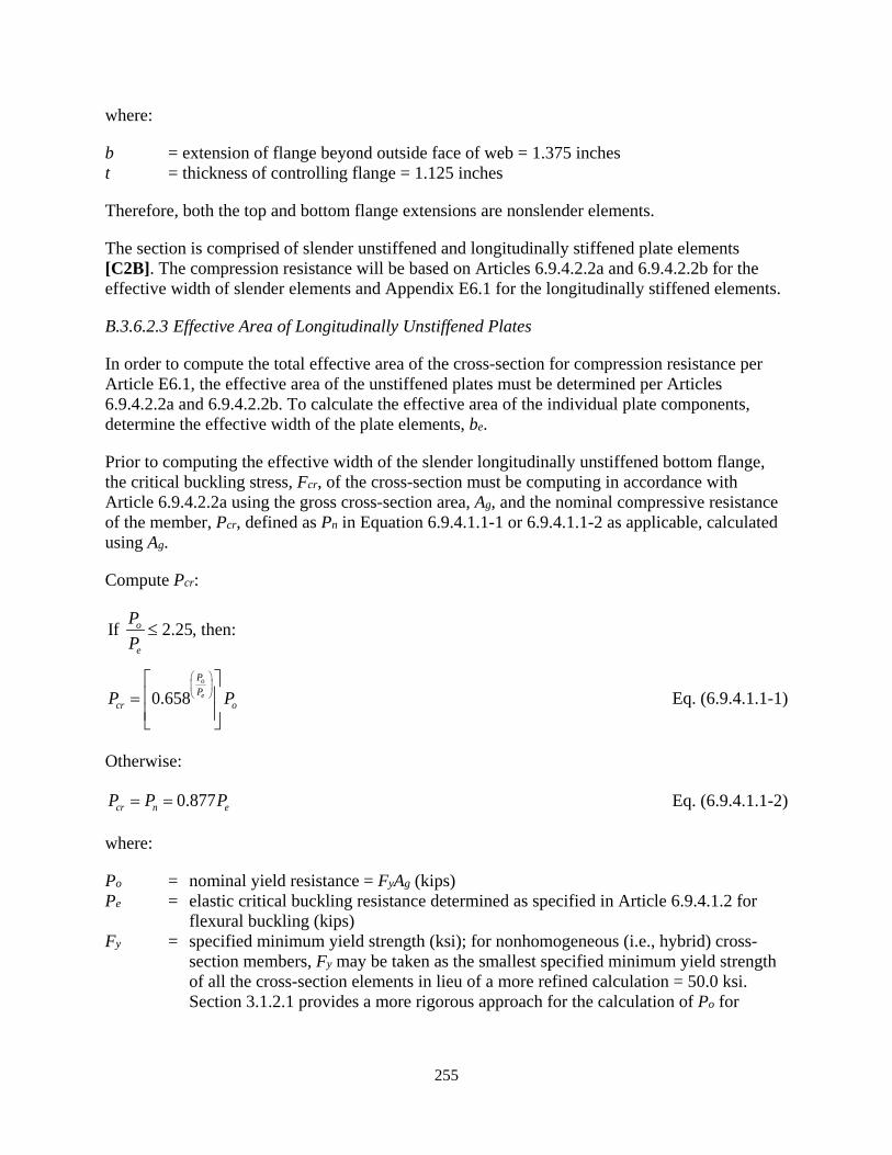
255
where:
b = extension of flange beyond outside face of web = 1.375 inches t = thickness of controlling flange = 1.125 inches
Therefore, both the top and bottom flange extensions are nonslender elements.
The section is comprised of slender unstiffened and longitudinally stiffened plate elements [C2B]. The compression resistance will be based on Articles 6.9.4.2.2a and 6.9.4.2.2b for the effective width of slender elements and Appendix E6.1 for the longitudinally stiffened elements.
B.3.6.2.3 Effective Area of Longitudinally Unstiffened Plates
In order to compute the total effective area of the cross-section for compression resistance per Article E6.1, the effective area of the unstiffened plates must be determined per Articles 6.9.4.2.2a and 6.9.4.2.2b. To calculate the effective area of the individual plate components, determine the effective width of the plate elements, be.
Prior to computing the effective width of the slender longitudinally unstiffened bottom flange, the critical buckling stress, Fcr, of the cross-section must be computing in accordance with Article 6.9.4.2.2a using the gross cross-section area, Ag, and the nominal compressive resistance of the member, Pcr, defined as Pn in Equation 6.9.4.1.1-1 or 6.9.4.1.1-2 as applicable, calculated using Ag.
Compute Pcr:
If 2.25, then:o
e
PP
≤
0.658o
e
PP
cr oP P
=
Eq. (6.9.4.1.1-1)
Otherwise:
0.877cr n eP P P= = Eq. (6.9.4.1.1-2)
where:
Po = nominal yield resistance = FyAg (kips) Pe = elastic critical buckling resistance determined as specified in Article 6.9.4.1.2 for
flexural buckling (kips)
Fy = specified minimum yield strength (ksi); for nonhomogeneous (i.e., hybrid) cross-section members, Fy may be taken as the smallest specified minimum yield strength of all the cross-section elements in lieu of a more refined calculation = 50.0 ksi. Section 3.1.2.1 provides a more rigorous approach for the calculation of Po for
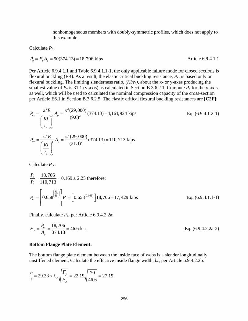
256
nonhomogeneous members with doubly-symmetric profiles, which does not apply to this example.
Calculate Po:
50(374.13) 18,706 kipso y gP F A= = = Article 6.9.4.1.1
Per Article 6.9.4.1.1 and Table 6.9.4.1.1-1, the only applicable failure mode for closed sections is flexural buckling (FB). As a result, the elastic critical buckling resistance, Pe, is based only on flexural buckling. The limiting slenderness ratio, (Kl/rs), about the x- or y-axes producing the smallest value of Pe is 31.1 (y-axis) as calculated in Section B.3.6.2.1. Compute Pe for the x-axis as well, which will be used to calculated the nominal compression capacity of the cross-section per Article E6.1 in Section B.3.6.2.5. The elastic critical flexural buckling resistances are [C2F]:
2 2
2 2
(29,000) (374.13) 1,161,924 kips(9.6)ex g
s x
EP AKlr
π π= = =
Eq. (6.9.4.1.2-1)
2 2
2 2
(29,000) (374.13) 110,713 kips(31.1)ey g
s y
EP AKlr
π π= = =
Calculate Pcr:
18,706 0.169 2.25 therefore:110,713
o
e
PP
= = ≤
( )0.1690.658 0.658 18,706 17,429 kipso
e
PP
cr oP P
= = =
Eq. (6.9.4.1.1-1)
Finally, calculate Fcr per Article 6.9.4.2.2a:
18,706 46.6 ksi374.13
crcr
g
PFA
= = = Eq. (6.9.4.2.2a-2)
Bottom Flange Plate Element:
The bottom flange plate element between the inside face of webs is a slender longitudinally unstiffened element. Calculate the effective inside flange width, be, per Article 6.9.4.2.2b:
7029.33 22.19 27.1946.6
yr
cr
Fbt F= > λ = =

257
Therefore, the effective inside flange width, be, is less than the width between the inside faces of the flanges, b, and calculated as [C2B]:
( )
2 2
1 222.19(1.74) (70) 121.2 ksi29.33
re yF c F
b t λ = = =
Eq. (6.9.4.2.2b-4)
1 11 31
121.2 121.244 1 0.22 0.075 42.48 inches46.6 46.6
e ee
cr cr
F Fb b c cF F
= − −
= − − =
Eq. (6.9.4.2.2b-2)
where:
c1 = effective width imperfection adjustment factor determined from Table 6.9.4.2.2b-1 for all other plates supported along two longitudinal edges = 0.22
c2 = effective width imperfection adjustment factor determined from Table 6.9.4.2.2b-1 for all other plates supported along two longitudinal edges = 1.74
c3 = effective width imperfection adjustment factor determined from Table 6.9.4.2.2b-1 for all other plates supported along two longitudinal edges = 0.075
Fe1 = elastic local buckling stress calculated per Equation 6.9.4.2.2b-4 (ksi)
After calculating be, use the term in Equation E6.1.1-8 related to slender longitudinally unstiffened plates to compute the effective area, Aeff, of the bottom flange between the inside face of webs:
2, 42.48(1.500) 63.72 incheff bf eA b t= = = Eq. (E6.1.1-8)
Comparing this result to the actual plate area calculated below shows the bottom flange is approximately 97% effective in resisting compression forces.
2, 44(1.500) 66.00 inchesf bA bt= = =
Flange Extension Elements:
The top and bottom flange extensions are nonslender, therefore calculate the effective area, Aeff, using the first term of Equation E6.1.1-8, substituting the full plate width, b, for be.:
2, 2(1.375)(1.125 1.500) 7.22 incheff ext eA b t bt= = = + =∑
Corner Pieces:
Per Article E6.1.1, the effective area, Aeff, of the corner pieces of the flanges, which are the portions directly under the web plates, is the gross cross-sectional area of these pieces. Calculate the area for the four corners:
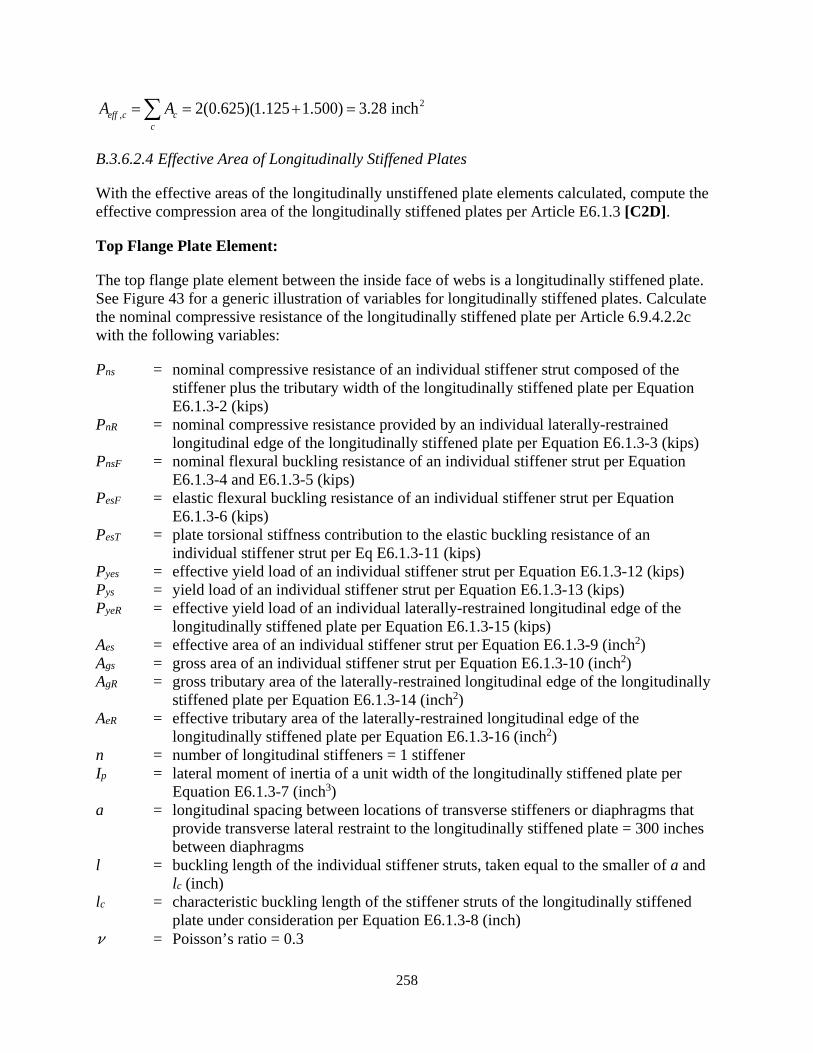
258
2, 2(0.625)(1.125 1.500) 3.28 incheff c c
cA A= = + =∑
B.3.6.2.4 Effective Area of Longitudinally Stiffened Plates
With the effective areas of the longitudinally unstiffened plate elements calculated, compute the effective compression area of the longitudinally stiffened plates per Article E6.1.3 [C2D].
Top Flange Plate Element:
The top flange plate element between the inside face of webs is a longitudinally stiffened plate. See Figure 43 for a generic illustration of variables for longitudinally stiffened plates. Calculate the nominal compressive resistance of the longitudinally stiffened plate per Article 6.9.4.2.2c with the following variables:
Pns = nominal compressive resistance of an individual stiffener strut composed of the stiffener plus the tributary width of the longitudinally stiffened plate per Equation E6.1.3-2 (kips)
PnR = nominal compressive resistance provided by an individual laterally-restrained longitudinal edge of the longitudinally stiffened plate per Equation E6.1.3-3 (kips)
PnsF = nominal flexural buckling resistance of an individual stiffener strut per Equation E6.1.3-4 and E6.1.3-5 (kips)
PesF = elastic flexural buckling resistance of an individual stiffener strut per Equation E6.1.3-6 (kips)
PesT = plate torsional stiffness contribution to the elastic buckling resistance of an individual stiffener strut per Eq E6.1.3-11 (kips)
Pyes = effective yield load of an individual stiffener strut per Equation E6.1.3-12 (kips) Pys = yield load of an individual stiffener strut per Equation E6.1.3-13 (kips) PyeR = effective yield load of an individual laterally-restrained longitudinal edge of the
longitudinally stiffened plate per Equation E6.1.3-15 (kips) Aes = effective area of an individual stiffener strut per Equation E6.1.3-9 (inch2) Ags = gross area of an individual stiffener strut per Equation E6.1.3-10 (inch2) AgR = gross tributary area of the laterally-restrained longitudinal edge of the longitudinally
stiffened plate per Equation E6.1.3-14 (inch2) AeR = effective tributary area of the laterally-restrained longitudinal edge of the
longitudinally stiffened plate per Equation E6.1.3-16 (inch2) n = number of longitudinal stiffeners = 1 stiffener Ip = lateral moment of inertia of a unit width of the longitudinally stiffened plate per
Equation E6.1.3-7 (inch3) a = longitudinal spacing between locations of transverse stiffeners or diaphragms that
provide transverse lateral restraint to the longitudinally stiffened plate = 300 inches between diaphragms
l = buckling length of the individual stiffener struts, taken equal to the smaller of a and lc (inch)
lc = characteristic buckling length of the stiffener struts of the longitudinally stiffened plate under consideration per Equation E6.1.3-8 (inch)
𝜈𝜈 = Poisson’s ratio = 0.3
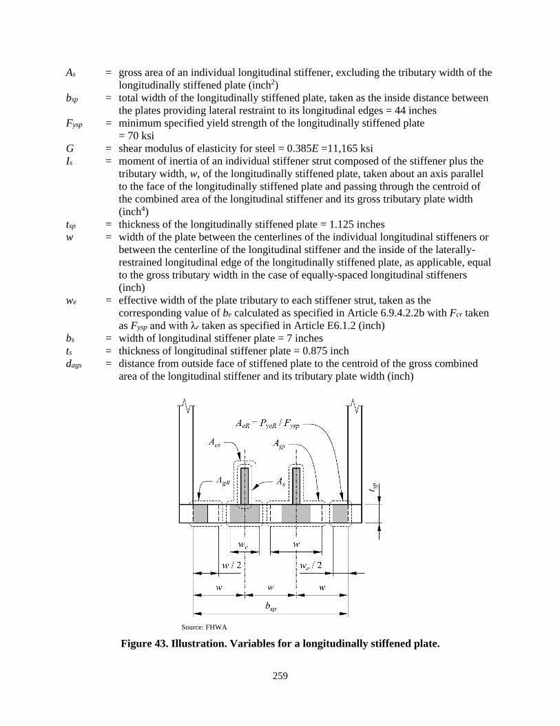
259
As = gross area of an individual longitudinal stiffener, excluding the tributary width of the longitudinally stiffened plate (inch2)
bsp = total width of the longitudinally stiffened plate, taken as the inside distance between the plates providing lateral restraint to its longitudinal edges = 44 inches
Fysp = minimum specified yield strength of the longitudinally stiffened plate = 70 ksi
G = shear modulus of elasticity for steel = 0.385E =11,165 ksi Is = moment of inertia of an individual stiffener strut composed of the stiffener plus the
tributary width, w, of the longitudinally stiffened plate, taken about an axis parallel to the face of the longitudinally stiffened plate and passing through the centroid of the combined area of the longitudinal stiffener and its gross tributary plate width (inch4)
tsp = thickness of the longitudinally stiffened plate = 1.125 inches w = width of the plate between the centerlines of the individual longitudinal stiffeners or
between the centerline of the longitudinal stiffener and the inside of the laterally-restrained longitudinal edge of the longitudinally stiffened plate, as applicable, equal to the gross tributary width in the case of equally-spaced longitudinal stiffeners (inch)
we = effective width of the plate tributary to each stiffener strut, taken as the corresponding value of be calculated as specified in Article 6.9.4.2.2b with Fcr taken as Fysp and with λr taken as specified in Article E6.1.2 (inch)
bs = width of longitudinal stiffener plate = 7 inches ts = thickness of longitudinal stiffener plate = 0.875 inch dags = distance from outside face of stiffened plate to the centroid of the gross combined
area of the longitudinal stiffener and its tributary plate width (inch)
Source: FHWA
Figure 43. Illustration. Variables for a longitudinally stiffened plate.
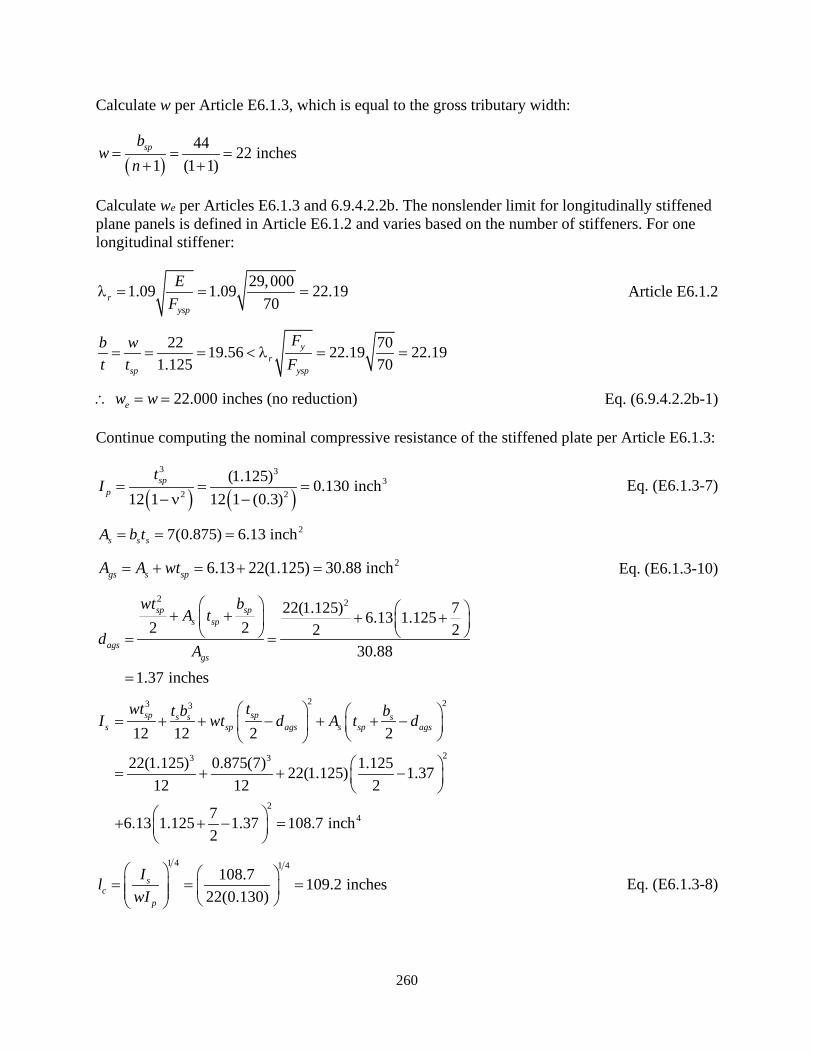
260
Calculate w per Article E6.1.3, which is equal to the gross tributary width:
( )44 22 inches
1 (1 1)spb
wn
= = =+ +
Calculate we per Articles E6.1.3 and 6.9.4.2.2b. The nonslender limit for longitudinally stiffened plane panels is defined in Article E6.1.2 and varies based on the number of stiffeners. For one longitudinal stiffener:
29,0001.09 1.09 22.1970r
ysp
EF
λ = = = Article E6.1.2
22 7019.56 22.19 22.191.125 70
yr
sp ysp
Fb wt t F= = = < λ = =
22.000 inches (no reduction)ew w∴ = = Eq. (6.9.4.2.2b-1)
Continue computing the nominal compressive resistance of the stiffened plate per Article E6.1.3:
( ) ( )3 3
32 2
(1.125) 0.130 inch12 1 12 1 (0.3)
spp
tI = = =
−ν − Eq. (E6.1.3-7)
27(0.875) 6.13 inchs s sA b t= = =
26.13 22(1.125) 30.88 inchgs s spA A wt= + = + = Eq. (E6.1.3-10)
2 222(1.125) 76.13 1.1252 2 2 230.88
1.37 inches
sp sps sp
agsgs
wt bA t
dA
+ + + + = =
=
2 23 3
23 3
24
12 12 2 2
22(1.125) 0.875(7) 1.12522(1.125) 1.3712 12 2
76.13 1.125 1.37 108.7 inch2
sp sps s ss sp ags s sp ags
wt tt b bI wt d A t d = + + − + + −
= + + −
+ + − =
1 4 1 4108.7 109.2 inches
22(0.130)s
cp
IlwI
= = =
Eq. (E6.1.3-8)
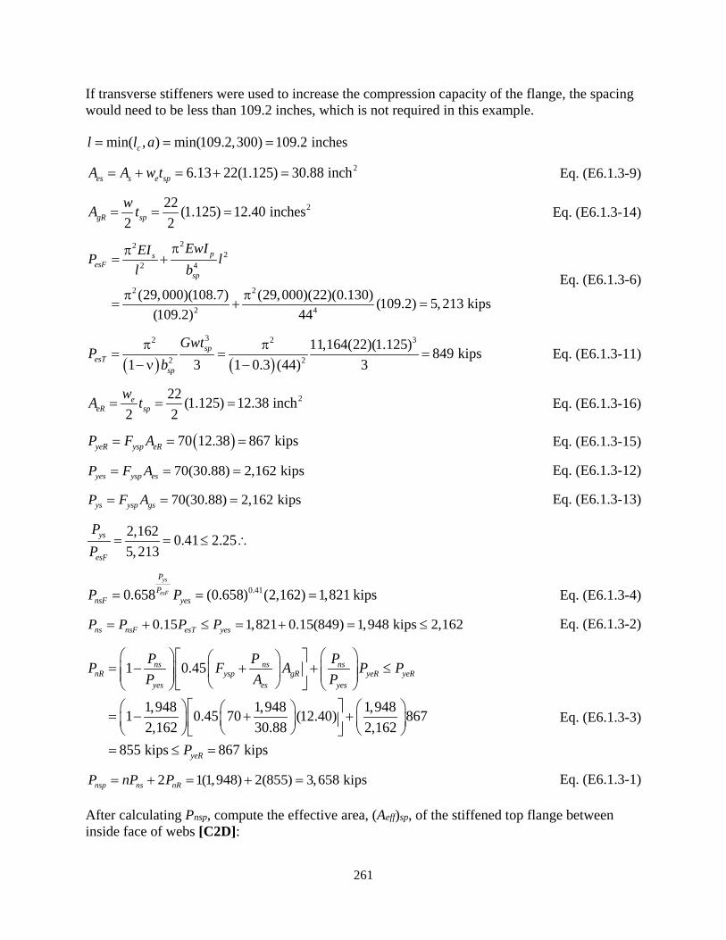
261
If transverse stiffeners were used to increase the compression capacity of the flange, the spacing would need to be less than 109.2 inches, which is not required in this example.
min( , ) min(109.2,300) 109.2 inchescl l a= = =
26.13 22(1.125) 30.88 inches s e spA A w t= + = + = Eq. (E6.1.3-9)
222 (1.125) 12.40 inches2 2gR spwA t= = = Eq. (E6.1.3-14)
222
2 4
2 2
2 4
(29,000)(108.7) (29,000)(22)(0.130) (109.2) 5,213 kips(109.2) 44
psesF
sp
EwIEIP ll b
ππ= +
π π= + =
Eq. (E6.1.3-6)
( ) ( )
32 2 3
2 2
11,164(22)(1.125) 849 kips1 3 1 0.3 (44) 3
spesT
sp
GwtP
bπ π
= = =−ν −
Eq. (E6.1.3-11)
222 (1.125) 12.38 inch2 2
eeR sp
wA t= = = Eq. (E6.1.3-16)
( )70 12.38 867 kipsyeR ysp eRP F A= = = Eq. (E6.1.3-15)
70(30.88) 2,162 kipsyes ysp esP F A= = = Eq. (E6.1.3-12)
70(30.88) 2,162 kipsys ysp gsP F A= = = Eq. (E6.1.3-13)
2,162 0.41 2.255,213
ys
esF
PP
= = ≤ ∴
0.410.658 (0.658) (2,162) 1,821 kipsys
esF
PP
nsF yesP P= = = Eq. (E6.1.3-4)
0.15 1,821 0.15(849) 1,948 kips 2,162ns nsF esT yesP P P P= + ≤ = + = ≤ Eq. (E6.1.3-2)
1 0.45
1,948 1,948 1,9481 0.45 70 (12.40) 8672,162 30.88 2,162
855 kips 867 kips
ns ns nsnR ysp gR yeR yeR
yes es yes
yeR
P P PP F A P PP A P
P
= − + + ≤
= − + + = ≤ =
Eq. (E6.1.3-3)
2 1(1,948) 2(855) 3,658 kipsnsp ns nRP nP P= + = + = Eq. (E6.1.3-1)
After calculating Pnsp, compute the effective area, (Aeff)sp, of the stiffened top flange between inside face of webs [C2D]:

262
23,658( ) 52.26 inches70
nspeff sp
ysp
PA
F= = = Eq. (E6.1.3-17)
Comparing this result to the gross area of the stiffened plate calculated below shows the top flange is 94% effective in resisting compression forces.
2, 44(1.125) 1(7)(0.875) 55.63 inchf t sp sp s sA b t nb t= + = + =
Web Plate Elements:
The web plate elements between the inside face of flanges are slender longitudinally stiffened plates. Calculate the nominal compressive resistance of a longitudinally stiffened web plate per Article E6.13 similar to the top flange with the following variables:
Fysp = 50 ksi a = 150 inches between diaphragms and intermediate transverse web stiffeners bsp = 168 inches tsp = 0.625 inch n = number of longitudinal stiffeners = 2 stiffeners bs = width of longitudinal stiffener plate = 8 inches ts = thickness of longitudinal stiffener plate = 1 inch
Calculate w per Article E6.1.3 (see Figure 42):
( )168 56 inches
1 (2 1)spb
wn
= = =+ +
Calculate we based on two longitudinal stiffeners:
29,0001.49 1.49 35.8850r
ysp
EF
λ = = = Article E6.1.2
56 5089.60 35.88 35.880.625 50
yr
sp ysp
Fb wt t F= = = > λ = =
Therefore, the longitudinally stiffened web plate panels are slender; calculate we per Article 6.9.4.2.2b. The web has two longitudinal stiffeners, therefore c1 = 0.18, c2 = 1.31, and c3 = 0.0:
( )
2 2
1 235.88(1.31) (50) 13.8 ksi89.60
re yF c F
b t λ = = =
Eq. (6.9.4.2.2b-4)
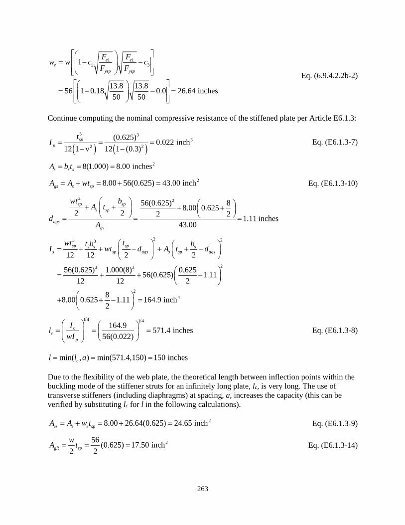
263
1 11 31
13.8 13.856 1 0.18 0.0 26.64 inches50 50
e ee
ysp ysp
F Fw w c cF F
= − −
= − − =
Eq. (6.9.4.2.2b-2)
Continue computing the nominal compressive resistance of the stiffened plate per Article E6.1.3:
( ) ( )3 3
32 2
(0.625) 0.022 inch12 1 12 1 (0.3)
spp
tI = = =
−ν − Eq. (E6.1.3-7)
28(1.000) 8.00 inchess s sA b t= = =
28.00 56(0.625) 43.00 inchgs s spA A wt= + = + = Eq. (E6.1.3-10)
2 256(0.625) 88.00 0.6252 2 2 2 1.11 inches43.00
sp sps sp
agsgs
wt bA t
dA
+ + + + = = =
2 23 3
23 3
24
12 12 2 2
56(0.625) 1.000(8) 0.62556(0.625) 1.1112 12 2
88.00 0.625 1.11 164.9 inch2
sp sps s ss sp ags s sp ags
wt tt b bI wt d A t d = + + − + + −
= + + −
+ + − =
1 4 1 4164.9 571.4 inches
56(0.022)s
cp
IlwI
= = =
Eq. (E6.1.3-8)
min( , ) min(571.4,150) 150 inchescl l a= = =
Due to the flexibility of the web plate, the theoretical length between inflection points within the buckling mode of the stiffener struts for an infinitely long plate, lc, is very long. The use of transverse stiffeners (including diaphragms) at spacing, a, increases the capacity (this can be verified by substituting lc for l in the following calculations).
28.00 26.64(0.625) 24.65 inches s e spA A w t= + = + = Eq. (E6.1.3-9)
256 (0.625) 17.50 inch2 2gR spwA t= = = Eq. (E6.1.3-14)

264
[ ]
22 2 22
2 4 2 4
(29,000)(164.9) (29,000)(56)(0.022) (150)(150) 168
2098 10 2,108 kips
psesF
sp
EwIEIP ll b
ππ π π= + = +
= + =
Eq. (E6.1.3-6)
The first term of PesF is the elastic flexural resistance of the stiffener strut and the second term is the resistance from transverse bending stiffness of the plate, which indicates that the thin web plate provides almost no lateral stiffness.
( ) ( )
32 2 3
2 2
11,164(56)(0.625) 25 kips1 3 1 0.3 (168) 3
spesT
sp
GwtP
bπ π
= = =−ν −
Eq. (E6.1.3-11)
From above, it can be seen that the resistance for plate torsional stiffness is negligible. As a result, the compression resistance is almost solely due to the elastic flexural buckling of the individual stiffened struts and the longitudinally restrained edges of the stiffened plate.
226.64 (0.625) 8.33 inch2 2
eeR sp
wA t= = = Eq. (E6.1.3-16)
( )50 8.33 417 kipsyeR ysp eRP F A= = = Eq. (E6.1.3-15)
50(24.65) 1,233 kipsyes ysp esP F A= = = Eq. (E6.1.3-12)
50(43.00) 2,150 kipsys ysp gsP F A= = = Eq. (E6.1.3-13)
2,150 1.02 2.252,108
ys
esF
PP
= = ≤ ∴
1.020.658 (0.658) (1,233) 805 kipsys
esF
PP
nsF yesP P= = = Eq. (E6.1.3-4)
0.15 805 0.15(25) 809 kips1,233 kips
ns nsF esT yes
yes
P P P PP
= + ≤ = + =
≤ = Eq. (E6.1.3-2)
1 0.45
809 809 8091 0.45 50 (17.50) 4171,233 24.65 1,233
498 417 kips
ns ns nsnR ysp gR yeR yeR
yes es yes
yeR
P P PP F A P PP A P
P
= − + + ≤
= − + + = ≤ =
Eq. (E6.1.3-3)
2 2(809) 2(417) 2,452 kipsnsp ns nRP nP P= + = + = Eq. (E6.1.3-1)
Note that this is only the capacity for one web. Additionally, for reference, if the buckling length of the stiffener, l, was increased to the characteristic length, lc, due to a lack of transverse stiffeners, the capacity, Pnsp, would drop to 1,132 kips.
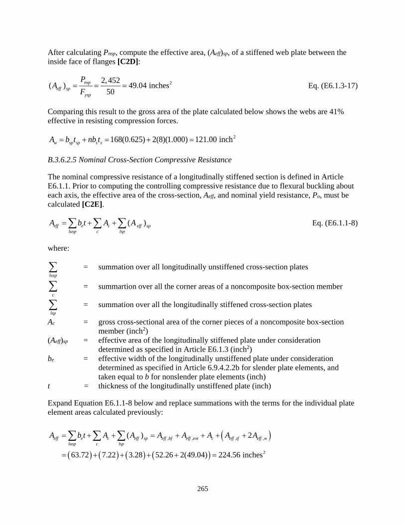
265
After calculating Pnsp, compute the effective area, (Aeff)sp, of a stiffened web plate between the inside face of flanges [C2D]:
22, 452( ) 49.04 inches50
nspeff sp
ysp
PA
F= = = Eq. (E6.1.3-17)
Comparing this result to the gross area of the plate calculated below shows the webs are 41% effective in resisting compression forces.
2168(0.625) 2(8)(1.000) 121.00 inchw sp sp s sA b t nb t= + = + =
B.3.6.2.5 Nominal Cross-Section Compressive Resistance
The nominal compressive resistance of a longitudinally stiffened section is defined in Article E6.1.1. Prior to computing the controlling compressive resistance due to flexural buckling about each axis, the effective area of the cross-section, Aeff, and nominal yield resistance, Po, must be calculated [C2E].
( )eff e c eff splusp c lsp
A b t A A= + +∑ ∑ ∑ Eq. (E6.1.1-8)
where:
lusp∑ = summation over all longitudinally unstiffened cross-section plates
c∑ = summartion over all the corner areas of a noncomposite box-section member
lsp∑ = summation over all the longitudinally stiffened cross-section plates
Ac = gross cross-sectional area of the corner pieces of a noncomposite box-section member (inch2)
(Aeff)sp = effective area of the longitudinally stiffened plate under consideration determined as specified in Article E6.1.3 (inch2)
be = effective width of the longitudinally unstiffened plate under consideration determined as specified in Article 6.9.4.2.2b for slender plate elements, and taken equal to b for nonslender plate elements (inch)
t = thickness of the longitudinally unstiffened plate (inch)
Expand Equation E6.1.1-8 below and replace summations with the terms for the individual plate element areas calculated previously:
( )
( ) ( ) ( ) ( )
, , , ,
2
( ) 2
63.72 7.22 3.28 52.26 2(49.04) 224.56 inches
eff e c eff sp eff bf eff ext c eff tf eff wlusp c lsp
A b t A A A A A A A= + + = + + + +
= + + + + =
∑ ∑ ∑
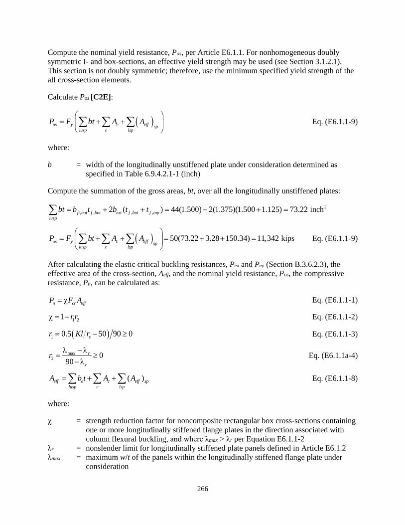
266
Compute the nominal yield resistance, Pos, per Article E6.1.1. For nonhomogeneous doubly symmetric I- and box-sections, an effective yield strength may be used (see Section 3.1.2.1). This section is not doubly symmetric; therefore, use the minimum specified yield strength of the all cross-section elements.
Calculate Pos [C2E]:
( )os y c eff splusp c lsp
P F bt A A
= + + ∑ ∑ ∑ Eq. (E6.1.1-9)
where:
b = width of the longitudinally unstiffened plate under consideration determined as specified in Table 6.9.4.2.1-1 (inch)
Compute the summation of the gross areas, bt, over all the longitudinally unstiffened plates:
2, , , ,2 ( ) 44(1.500) 2(1.375)(1.500 1.125) 73.22 inchfi bot f bot ext f bot f top
luspbt b t b t t= + + = + + =∑
( ) 50(73.22 3.28 150.34) 11,342 kipsos y c eff splusp c lsp
P F bt A A
= + + = + + = ∑ ∑ ∑ Eq. (E6.1.1-9)
After calculating the elastic critical buckling resistances, Pex and Pey (Section B.3.6.2.3), the effective area of the cross-section, Aeff, and the nominal yield resistance, Pos, the compressive resistance, Pn, can be calculated as:
n cr effP F A= χ Eq. (E6.1.1-1)
1 21 r rχ = − Eq. (E6.1.1-2)
( )1 0.5 50 90 0sr Kl r= − ≥ Eq. (E6.1.1-3)
max2 0
90r
r
r λ −λ= ≥
−λ Eq. (E6.1.1a-4)
( )eff e c eff splusp c lsp
A b t A A= + +∑ ∑ ∑ Eq. (E6.1.1-8)
where:
χ = strength reduction factor for noncomposite rectangular box cross-sections containing one or more longitudinally stiffened flange plates in the direction associated with column flexural buckling, and where λmax > λr per Equation E6.1.1-2
λr = nonslender limit for longitudinally stiffened plate panels defined in Article E6.1.2 λmax = maximum w/t of the panels within the longitudinally stiffened flange plate under
consideration

267
Kl = effective length in the plane of buckling (inch) rs = radius of gyration about the axis normal to the plane of buckling using the gross-
section properties (inch)
The cross-section contains longitudinally stiffened plates, therefore, χ may not equal 1.0 and the nominal compression resistance, Pn, must be calculated for each axis of flexural buckling to determine the minimum, controlling value. The elastic crtical flexural buckling resistances, Pex and Pey, were computed previously in Section B.2.6.2.3 [C2F].
For the calculation of (Aeff)sp of the top flange, λr and λmax were computed in Section B.3.6.2.4 indicating λmax = 19.56 < λr = 22.19 [C2G]; therefore a strength reduction is not required. Calculate Pnx:
1.0xχ = [C2H] Eq. (E6.1.1-5)
11,342 0.010 2.25 therefore:1,161,924
os
ex
PP
= = ≤
( ), 0.010, 0.658 0.658 50 49.8 ksi
os
e x
PP
cr x yF F
= = =
[C2H] Eq. (E6.1.1-6)
, 1.0(49.8)(224.56) 11,183 kipsnx x cr x effP F A= χ = = Eq. (E6.1.1-1)
For the calculation of (Aeff)sp of the webs, λr and λmax were computed in Section B.3.6.2.4indicating λmax = 89.60 > λr = 35.88 [C2G]; therefore a strength reduction factor calculation is required. Calculate Pny:
( ) ( )1 0.5 50 90 0.5 31.1 50 90 0.11 0sr Kl r= − = − = − ≥ Eq. (E6.1.1-3)
max2
89.6 35.9 0.99 090 90 35.9
r
r
r λ −λ −= = = ≥
−λ − Eq. (E6.1.1-4)
1 21 1 0(0.99) 1.0y r rχ = − = − = [C2I] Eq. (E6.1.1-2)
11,342 0.102 2.25 therefore:110,713
os
ey
PP
= = ≤
( ), 0.102, 0.658 0.658 50 47.9 ksi
os
e y
PP
cr y yF F
= = =
[C2I] Eq. (E6.1.1-6)
, 1.0(47.9)(224.56) 10,756 kipsny y cr y effP F A= χ = = Eq. (E6.1.1-1)
The nominal compression resistance of the member is the minimum value of the two axes [C2J]:
min( , ) min(11,183, 10,756) 10,756 kipsn nx nyP P P= = =
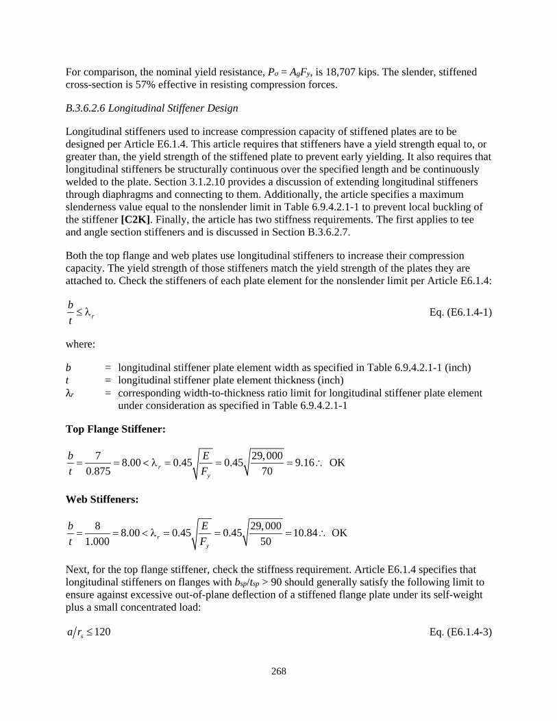
268
For comparison, the nominal yield resistance, Po = AgFy, is 18,707 kips. The slender, stiffened cross-section is 57% effective in resisting compression forces.
B.3.6.2.6 Longitudinal Stiffener Design
Longitudinal stiffeners used to increase compression capacity of stiffened plates are to be designed per Article E6.1.4. This article requires that stiffeners have a yield strength equal to, or greater than, the yield strength of the stiffened plate to prevent early yielding. It also requires that longitudinal stiffeners be structurally continuous over the specified length and be continuously welded to the plate. Section 3.1.2.10 provides a discussion of extending longitudinal stiffeners through diaphragms and connecting to them. Additionally, the article specifies a maximum slenderness value equal to the nonslender limit in Table 6.9.4.2.1-1 to prevent local buckling of the stiffener [C2K]. Finally, the article has two stiffness requirements. The first applies to tee and angle section stiffeners and is discussed in Section B.3.6.2.7.
Both the top flange and web plates use longitudinal stiffeners to increase their compression capacity. The yield strength of those stiffeners match the yield strength of the plates they are attached to. Check the stiffeners of each plate element for the nonslender limit per Article E6.1.4:
rbt≤ λ Eq. (E6.1.4-1)
where:
b = longitudinal stiffener plate element width as specified in Table 6.9.4.2.1-1 (inch) t = longitudinal stiffener plate element thickness (inch) λr = corresponding width-to-thickness ratio limit for longitudinal stiffener plate element
under consideration as specified in Table 6.9.4.2.1-1
Top Flange Stiffener:
7 29,0008.00 0.45 0.45 9.16 OK0.875 70r
y
b Et F= = < λ = = = ∴
Web Stiffeners:
8 29,0008.00 0.45 0.45 10.84 OK1.000 50r
y
b Et F= = < λ = = = ∴
Next, for the top flange stiffener, check the stiffness requirement. Article E6.1.4 specifies that longitudinal stiffeners on flanges with bsp/tsp > 90 should generally satisfy the following limit to ensure against excessive out-of-plane deflection of a stiffened flange plate under its self-weight plus a small concentrated load:
120sa r ≤ Eq. (E6.1.4-3)

269
s s gsr I A= Eq. (E6.1.4-4)
where:
a = longitudinal spacing between locations of transverse stiffeners or diaphragms that provide transverse lateral restraint to the longitudinally stiffened plate under consideration (inch)
Ags = gross area of an individual stiffener strut as defined in Article E6.1.3 (inch2) Is = moment of inertia of an individual stiffener strut as defined in Article E6.1.3 (inch4)
The variables a, Ags, and Is were calculated in Section B.3.6.2.4 for the top flange. Using those values, check stiffness:
Top Flange Stiffener:
108.7 30.88 1.88 inchs s gsr I A= = =
300 1.88 159.6 120sa r = = >
Therefore the top flange stiffener does not satisfy this limit. However, it should be noted that the top flange satisfies the bsp/tsp limit of 90 for an unstiffened flange in Article 6.12.2.2.2b so this provision for preventing excessive deflections is not applicable to the top flange in this case, as specified in Article E6.1.4.
The longitudinal stiffeners are adequate for plate compression. However, if the stiffener serves as a longitudinal stiffener for a web plate in flexure, either in the calculation of Rb or for increased shear strength, it must also be designed per the provisions of Article 6.10.11.3. The top flange does not require the longitudinal stiffeners for strength when acting as a web in flexure and therefore does not need to satisfy these requirements per Section 3.2.2.2. However, the webs, due to their slenderness must be stiffened to satisfy the web cross-section proportion limits for longitudinally stiffened webs in Article 6.12.2.2.2b. Therefore, the longitudinal stiffeners must meet the requirements of Article 6.10.11.3. The stiffener dimensions will be checked for these requirements in Section B.3.6.4.6, which covers flexure about the x-axis.
B.3.6.2.7 Optional Longitudinal Flange Stiffener
Article E6.1.4 allows the use of tee or angle sections for longitudinal stiffeners. If used, they must satisfy the requirements of both Equation E6.1.4-1 and E6.1.4-2. This section provides an example of an angle shape stiffener for those provisions only. Transverse stiffener calculations for this longitudinal stiffener are not performed. For this example, assume a L6x4x0.75 angle with the long leg welded to the stiffened flange and the x-axis of the angle parallel to the short leg.
Check the angle stiffener for the nonslender limit per Equation E6.1.4-1 for both the long leg welded to the stiffened plate (supported along two edges) and the outstanding short leg (supported along one edge):

270
Long Leg (attached):
5.250 29,0007.00 1.09 1.09 26.3 OK0.750 50r
y
b Et F= = < λ = = = ∴ Eq. (E6.1.4-1)
where:
λr = corresponding width-to-thickness ratio limit for the longitudinal stiffener plate element under consideration as specified in Table 6.9.4.2.1-1
b = longitudinal stiffener plate element width as specified in Table 6.9.4.2.1-1, which is the clear distance between the stiffened plate and opposite angle leg = 5.250 inches
t = longitudinal stiffener plate element thickness = 0.750 inches Fy = specified minimum yield strength of the longitudinal stiffener.
Short Leg (outstanding):
4 29,0005.33 0.45 0.45 10.8 OK0.750 50r
y
b Et F= = < λ = = = ∴
where:
b = width outstanding leg of single angle = 4 inches
Therefore, the angle is nonslender and satisfies the requirements of Equation E6.1.4-1.
Tee and angle sections must also be checked for torsional buckling, also known as tripping, per Equation E6.1.4-2. For this check, the relevant properties of the L6x4x0.75 angle taken from AISC (2016) are:
6.000 inchesllb =
4.000 inchesslb =
0.750 inchest = 26.94 inchgA =
424.5 inchxI =
2.07 inchesy = 48.63 inchyI =
1.07 inchesx = 41.31 inchJ =

271
Calculate the polar moment of inertia of the longitudinal stiffener alone, Ips, about the attached edge. This is equal to the sum of the moments of inertia about the x and y-axes taken at the point where the centerline of the long leg is attached to the stiffened plate:
( )( )
( )( )
22
22 4
2
0.75024.5 6.94 6 2.07 8.63 6.94 1.07 143.7 inch2
ps x g ll y gtI I A b y I A x
= + − + + − = + − + + − =
Check that Equation E6.1.4-2 is satisfied:
1.31 500.0091 5.0 5.0 0.0086143.7 29,000
ys
ps
FJI E
= = > = = . Eq. (E6.1.4-2)
where:
Fy = specified minimum yield strength of the longitudinally stiffened plate element under consideration (ksi); however, the controlling lower yield strength of the stiffener (50 ksi) is used in this instance over the higher yield strength of the flange (70ksi)
Js = St. Venant torsional constant of the longitudinal stiffener alone, not including the contribution from the stiffened plate (inch4)
Ips = polar moment of inertia of the longitudinal stiffener alone about the attached edge (inch4)
Therefore, the L6x4x0.75 angle is adequate as a longitudinal stiffener per Article E6.1.4.
Note that there a limited number of angle sections that satisfy the requirements of Equation E6.1.4-2. For a yield strength of 50 ksi, sections where the length of the long leg divided by the thickness of the angle is less than 8.00 will generally satisfy this requirement. If the ratio for the long leg is equal to 8.00, the angle will generally satisfy the requirement if the ratio of the short leg to the thickness is less than 8.00. If the ratio of the long leg to the thickness is greater than 8.00, the section will likely not satisfy the requirements.
B.3.6.2.8 Transverse Stiffener Design
Article E6.1.5 covers the design of transverse stiffeners used to brace the longitudinal stiffeners of a stiffened compression plate element. If transverse stiffeners are spaced at distance, a, less than the longitudinal stiffeners characteristic length, lc, as described in Article E6.1.3, they reduce the unbraced length of the longitudinal stiffener and increase its capacity. If the transverse stiffeners, used for other reasons such as diaphragms to retain the shape of the box or to increase the shear strength of the plate element, have a spacing greater than lc, they do not increase the capacity of the longitudinal stiffeners. In this case, and when not subjected to any internal axial compression loads or directly applied external loads, the requirements of Article E6.1.5.2 may be waived. There are multiple methods for detailing transverse stiffeners. Section 3.1.2.11 provides

272
a discussion on the different types of transverse stiffening and the design forces for their connections [C2K].
The characteristic length of the top flange longitudinal stiffener is 109.2 inches, which is much less than the 300-inch spacing between diaphragms. Stiffening the top flange at a spacing less than 109.2 inches would not produce practical benefits. Therefore the requirements of Article E6.1.5 do not apply to the top flange. The characteristic length of the web plate longitudinal stiffeners is 569 inches, which exceeds the spacing of the diaphragms. Therefore the diaphragms provide transverse support to the longitudinal stiffeners. As discussed later, due to the robustness of the diaphragms, they can be assumed to satisfy these provisions if the access hole is not of a significant size in relation to the dimensions of the box, the diaphragm thickness is reasonable, and the diaphragm is not subjected to externally applied loads. However, for the tie girder, the longitudinal web stiffeners must be sized per Article 6.10.11.3 as described in Section B.3.6.2.6. This requires transverse stiffeners at a spacing equal to 2D or less, which is 336 inches, and still greater than the spacing of the diaphragms. However, as will be shown in the calculations for flexure about the x-axis, a transverse spacing of 150 inches, or half the distance between diaphragms, prevents the required dimensions for the longitudinal stiffener acting in flexure from being too excessive. Therefore, detail a plate transverse stiffener in between diaphragms and design per Article E6.1.5.2.
For transverse stiffeners required to satisfy the provisions of Article E6.1.5.1, the stiffener must satisfy moment of inertia and Article E6.1.4 dimensional checks as applicable. Additionally, the article specifies design forces for the connection of the transverse stiffener to the longitudinal stiffener. The requirements for moment of inertia are:
3
min
0.5 up spt
P bI
a E≥ Eq. (E6.1.5.2-1)
and
3
min
0.0009 0.02 up spt
y sp
P bE cIF b a E
≥ +
Eq. (E6.1.5.2-2)
where:
amin = smallest of the longitudinal spacings to the adjacent transverse stiffeners or diaphragms providing lateral restraint to the plate (inch)
c = largest distance from the neutral axis to the extreme fiber of the transverse stiffener considered in the calculation of It (inch)
bsp = total inside width between the plate elements providing lateral restraint to the longitudinal edges of the plate under consideration (inch)
Fy = smallest specified minimum yield strength of the stiffened plate and transverse stiffener under consideration (ksi)
It = moment of inertia of the transverse stiffener, including a width of the stiffened plate equal to 9tsp, but not more than the actual dimension available, on each side of the stiffener avoiding any overlap with contributing parts to adjacent stiffeners or
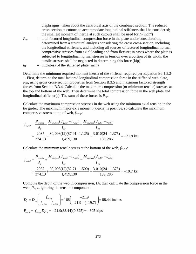
273
diaphragms, taken about the centroidal axis of the combined section. The reduced cross-section at cutouts to accommodate longitudinal stiffeners shall be considered; the smallest moment of inertia at such cutouts shall be used for It (inch4)
Pup = total factored longitudinal compression force in the plate under consideration, determined from a structural analysis considering the cross cross-section, including the longitudinal stiffeners, and including all sources of factored longitudinal normal compressive stresses from axial loading and from flexure; in cases where the plate is subjected to longitudinal normal stresses in tension over a portion of its width, the tensile stresses shall be neglected in determining this force (kip)
tsp = thickness of the stiffened plate (inch)
Determine the minimum required moment inertia of the stiffener required per Equation E6.1.5.2-1. First, determine the total factored longitudinal compression force in the stiffened web plate, Pup, using gross cross-section properties from Section B.3.5 and maximum factored strength forces from Section B.3.4. Calculate the maximum compression (or minimum tensile) stresses at the top and bottom of the web. Then determine the total compression force in the web plate and longitudinal stiffener(s). The sum of these forces is Pup.
Calculate the maximum compression stresses in the web using the minimum axial tension in the tie girder. The maximum major-axis moment (x-axis) is positive, so calculate the maximum compressive stress at top of web, fw,top:
,max , , ,max ,,min,
( ) ( )
2037 30,098(12)(87.91 1.125) 3,010(24 1.375) 21.9 ksi374.13 1,459,130 139,286
ux g top f top uy g LT extuw top
g xg yg
M d t M d bPf
A I I− −
= − −
− −= − − = −
Calculate the minimum tensile stress at the bottom of the web, fw,bot:
,max , , ,max ,,min,
( ) ( )
2037 30,098(12)(82.71 1.500) 3,010(24 1.375) 19.7 ksi374.13 1,459,130 139,286
ux g bot f bot uy g LT extuw bot
g xg yg
M d t M d bPf
A I I− −
= + −
− −= + − = +
Compute the depth of the web in compression, Dc, then calculate the compression force in the web, Pup,w, ignoring the tension component:
,
, ,
21.9168 88.44 inches21.9 ( 19.7)
w topc w
w top w bot
fD D
f f −
= = = − − − +
, , 21.9(88.44)(0.625) 605 kipsup w w top c wP f D t= = − = −
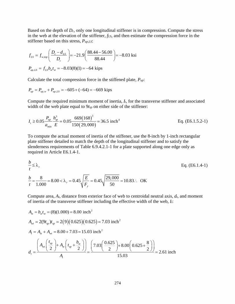
274
Based on the depth of Dc, only one longitudinal stiffener is in compression. Compute the stress in the web at the elevation of the stiffener, fLS, and then estimate the compression force in the stiffener based on this stress, Pup,LS:
,88.44 56.0021.9 8.03 ksi
88.44c LS
LS w topc
D df fD
− − = = − = −
, 8.03(8)(1) 64 kipsup LS LS st stP f b t= = − = −
Calculate the total compression force in the stiffened plate, Pup:
, , 605 ( 64) 669 kipsup up w up LSP P P= + = − + − = −
Compute the required minimum moment of inertia, It, for the transverse stiffener and associated width of the web plate equal to 9tsp on either side of the stiffener:
( )( )
334
min
669 1680.05 0.05 36.5 inch
150 29,000up sp
t
P bI
a E≥ = = Eq. (E6.1.5.2-1)
To compute the actual moment of inertia of the stiffener, use the 8-inch by 1-inch rectangular plate stiffener detailed to match the depth of the longitudinal stiffener and to satisfy the slenderness requirements of Table 6.9.4.2.1-1 for a plate supported along one edge only as required in Article E6.1.4-1.
rbt≤ λ Eq. (E6.1.4-1)
8 29,0008.00 0.45 0.45 10.83 OK1.000 50r
y
b Et F= = < λ = = = ∴
Compute area, At, distance from exterior face of web to centroidal neutral axis, dt, and moment of inertia of the transverse stiffener including the effective width of the web, It:
2(8)(1.000) 8.00 inchst st stA b t= = =
( )( )( ) 22(9 ) 2 9 0.625 0.625 7.03 inchwt sp spA t t= = =
28.00 7.03 15.03 incht st wtA A A= + = + =
0.625 87.03 8.00 0.6252 2 2 2 2.61 inch15.03
sp stwt st sp
tt
t bA A td
A
+ + + + = = =
275
( ) 23 23
2 23 3
4 4
2 912 12 2 2
2(9)(0.625)(0.625) 1(8) 0.625 87.03 2.61 8.00 0.625 2.6112 12 2 2
112.5 inch 36.5 inch OK
sp sp spst st stt wt t st sp t
t t tt b bI A d A t d = + + − + + −
= + + − + + −
= > ∴
where:
Ast = area of the transverse stiffener plate element only (inch2) Awt = area of tributary web acting with transverse stiffener equal to 9tsp on either side of
the stiffener per Article E6.1.5.2 At = total area of the effective transverse stiffener (inch2) dt = distance from centroidal axis of effective transverse stiffener section to outside face
of web (inch)
With the first moment of inertia requirement satisfied, check the second requirement from Article E6.1.5.2. First calculate the largest distance, c, from the neutral axis to the extreme fiber of the transverse stiffener considered in the calculation of It:
0.625 8.000 2.61 6.02 inchesw st tc t b d= + − = + − =
3
min
3
4 4
0.0009 0.02
29,000 6.02 669 1680.0009 0.0250 168 150 29,000
28.2 inch 112.5 inch OK
up spt
y sp
P bE cIF b a E
≥ +
= +
= < ∴
Eq. (E6.1.5.2-2)
Additionally, Article E6.1.5.1 states that the transverse stiffeners generally should have a moment of inertia greater than or equal to that of the longitudinal stiffeners. Compare the transverse stiffener moment of inertia, It, compute above to the longitudinal stiffener moment of inertia, Is, computed in Section B.3.6.2.4:
112.5 108.7 OKt sI I= > = ∴ Article E6.1.5.1
If the transverse stiffener was a tee or angle shape, it would need to satisfy the polar moment of inertia requirements of Equation E6.1.4-2 per Article E6.1.5.1.
The final check is in Section 3.1.2.11, which defines the design forces for the connection between the transverse and longitudinal stiffeners, Vul, as well as the connection at the end of the transverse stiffener to the web, Vut. In both of these cases, the force is acting in the direction perpendicular to the stiffened plate, where the longitudinal stiffener is trying to push into or pull away from the transverse stiffener. Begin by calculating the force between the longitudinal and transverse stiffeners:
276
0.01ul ups ulV P V= +
where:
Pups = factored axial force within the longitudinal stiffener strut under consideration, composed of the longitudinal stiffener and the tributary plate width, determined from a structural analysis considering the gross cross-section (kip)
Vul1 = first-order force transferred by the attachment due to any directly applied factored loads on the longitudinal stiffener perpendicular to the plane of the stiffened plate, as applicable (kip)
From the calculation of Pup, in Section B.3.6.5.6, the web stress at the level of the longitudinal stiffener, fLS, estimate Pups as this stress times the gross area of the stiffener, Ags:
8.03(43.00) 345 kipsups LS gsP f A= = =
Calculate the connection force, Vul, where Vul1 is zero for this example because there are no internal axial loads or directly applied external loads:
0.01 0.01(345) 3.5 kipsul upsV P= = =
Next, calculate the connection force between the end of the transverse stiffener and the web plate, which are the box flanges in this case, where the second and third terms are zero for transverse stiffeners without internal axial loads or externally applied loads:
10.005 0.01sput up ut ut
bV P P V
a
= + +
where:
Put = direct factored axial compression force in the transverse stiffener, as applicable (kip) Vul1 = first-order force in the direction perpendicular to the plane of the stiffened plate at
the attachment due to any directly applied factored loads, as applicable (kip)
11680.005 0.01 0.005(669) 0 0 3.7 kips150
sput up ut ut
bV P P V
a = + + = + + =
Size the fillet welds on both sides of the transverse stiffener connected to the longitudinal stiffener to resist Vul. Additionally, because the longitudinal stiffener interrupts the transverse stiffener plate, the welds must also be sized to transmit the moment, Mu, developed in the transverse stiffener due to the concentrated Vul load(s) across this connection.
For this example, that force would be the portion of Mu resisted by the transverse stiffener plate. Calculate this moment using Vut at the connection of the transverse stiffener to the web, which is assumed to be a simple connection, times the distance from the web to the stiffener:
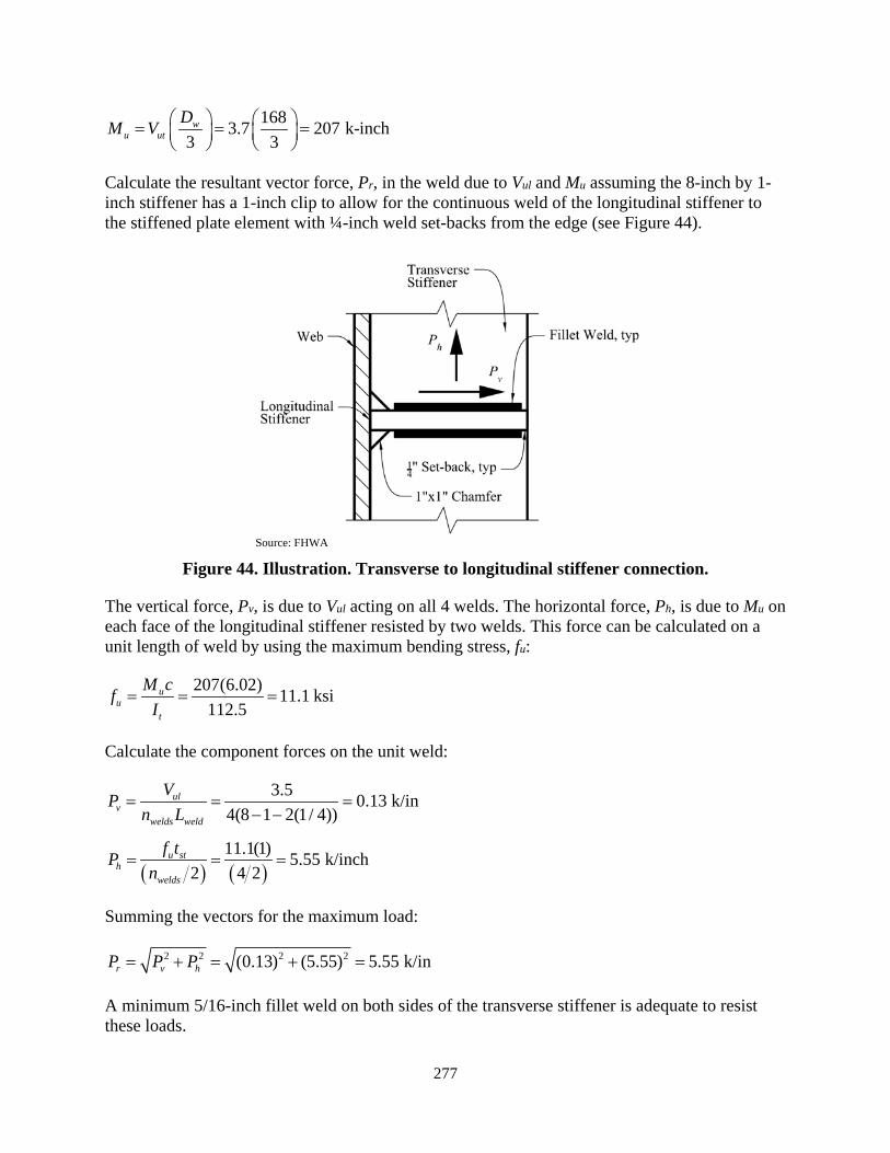
277
1683.7 207 k-inch3 3
wu ut
DM V = = =
Calculate the resultant vector force, Pr, in the weld due to Vul and Mu assuming the 8-inch by 1-inch stiffener has a 1-inch clip to allow for the continuous weld of the longitudinal stiffener to the stiffened plate element with ¼-inch weld set-backs from the edge (see Figure 44).
Source: FHWA
Figure 44. Illustration. Transverse to longitudinal stiffener connection.
The vertical force, Pv, is due to Vul acting on all 4 welds. The horizontal force, Ph, is due to Mu on each face of the longitudinal stiffener resisted by two welds. This force can be calculated on a unit length of weld by using the maximum bending stress, fu:
207(6.02) 11.1 ksi112.5
uu
t
M cfI
= = =
Calculate the component forces on the unit weld:
3.5 0.13 k/in4(8 1 2(1/ 4))
ulv
welds weld
VPn L
= = =− −
( ) ( )11.1(1) 5.55 k/inch
2 4 2u st
hwelds
f tPn
= = =
Summing the vectors for the maximum load:
2 2 2 2(0.13) (5.55) 5.55 k/inr v hP P P= + = + =
A minimum 5/16-inch fillet weld on both sides of the transverse stiffener is adequate to resist these loads.
278
The connection of the transverse stiffener to the web is assumed to act as a simple span between the longitudinally restrained edges, therefore the continuity forces do not apply and the factored design force is equal to the vertical force due to Vut. Based on inspection, the minimum required weld size is capable of resisting Pr:
3.7 0.28 k/inch2(6.5)
utr v
welds weld
VP Pn L
= = = =
This covers the design of the rectangular plate stiffeners. As mentioned previously, diaphragms can generally be assumed to satisfy these requirements. It can be seen that a diaphragm of adequate thickness (i.e., 1 inch similar to the thickness of the transverse stiffeners) located between the floor beams, without external loads, will have a capacity exceeding the 8-inch by 1-inch plate stiffeners used above. The connection of the longitudinal stiffeners to the diaphragm must be designed to resist Vul, however because the diaphragm is coped around the longitudinal stiffener, continuity through the connection is not required. See Section 3.1.2.11 for a discussion of potential connection details. While the diaphragm may be assumed adequate in these cases, the following items should necessitate further design, whether through a rational conservative method using hand calculations or a rigorous finite element analysis when the capacity of the diaphragm appears to be critical:
• If the access hole in the diaphragm is large compared to the inside dimension of the box, the remaining portions of the diaphragms will act more like rectangular plate transverse stiffeners than a diaphragm. In these cases, an equivalent rectangular plate stiffener could be assumed and designed.
• If the diaphragm is at the location of an externally applied load, such as a floor beam, the transfer of those forces into the diaphragm and the rest of the box cross-section must be considered in the stress distribution of the diaphragm and its connections to the flange and web plates. For example, the moment and eccentric shear applied by the floor beam will induce concentrated loads at the box-flange locations and a torsion on the diaphragm and box-section. If the diaphragm elements are designed as equivalent rectangular plate stiffeners, the resulting forces Vul1, Put and Vut1 must be considered. Otherwise, a rational method must be used to size the diaphragm and design the connections to the flanges and webs.
• If the box-section is subjected to high cross-section warping stresses causing distortion, the forces in the diaphragm to retain the shape of the cross-section must be considered as well. Cross-section distortion is discussed later in this document.
The design of the diaphragms at the floor beams for the externally applied forces is beyond the scope of this report and calculations are not provided.
Finally, because the web longitudinal stiffener serves as a longitudinal stiffener for a web plate in flexure, for the calculation of Rb and for increased shear strength, the transverse stiffener must also be designed per the provisions of Article 6.10.11.1. The transverse stiffener dimensions will be checked for these requirements in the section that covers shear in the direction of the y-axis.

279
B.3.6.2.9 Factored Compression Resistance
The tie girder is not subjected to axial compression, however, compute the factored resistance to demonstrate the calculation. The factored compression resistance of the member is specified in Article 6.9.2.1 as:
r c nP P= φ Eq. (6.9.2.1-1)
0.95(10,756) 10,218 kipsrP = =
where:
ϕc = resistance factor for axial compression, steel only, as specified in Article 6.5.4.2 = 0.95
Pn = nominal compressive resistance as specified in Article 6.9.4 for noncomposite members (kips)
B.3.6.3 Tension
The tie girder is subjected to axial tension forces. The factored tensile resistance will be computed in accordance with Article 6.8.
B.3.6.3.1 Limiting Slenderness Ratio
Article 6.8.4 specifies the maximum slenderness ratio for primary tensile members:
200Klr≤
Per Section B.3.6.2.1, the minimum slenderness ratio is 31.0 for (Kl/r)y. Therefore:
31.1 200 OKy
Klr
= ≤ ∴
B.3.6.3.2 Factored Tensile Resistance
Article 6.8.2.1 defines the factored tensile resistance, Pr, as the lesser of:
ry y ny y y gP P F A= φ = φ Eq. (6.8.2.1-1)
ru u nu u u n pP P F A R U= φ = φ Eq. (6.8.2.1-2)
where:
ϕy = resistance factor for tension, yielding in gross section, as specified in Article 6.5.4.2 = 0.95
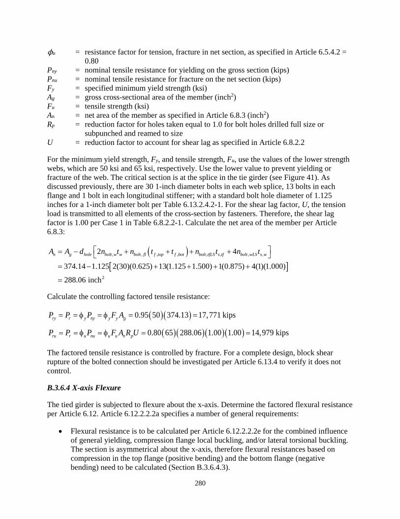
280
ϕu = resistance factor for tension, fracture in net section, as specified in Article 6.5.4.2 = 0.80
Pny = nominal tensile resistance for yielding on the gross section (kips) Pnu = nominal tensile resistance for fracture on the net section (kips) Fy = specified minimum yield strength (ksi) Ag = gross cross-sectional area of the member (inch2) Fu = tensile strength (ksi) An = net area of the member as specified in Article 6.8.3 (inch2) Rp = reduction factor for holes taken equal to 1.0 for bolt holes drilled full size or
subpunched and reamed to size U = reduction factor to account for shear lag as specified in Article 6.8.2.2
For the minimum yield strength, Fy, and tensile strength, Fu, use the values of the lower strength webs, which are 50 ksi and 65 ksi, respectively. Use the lower value to prevent yielding or fracture of the web. The critical section is at the splice in the tie girder (see Figure 41). As discussed previously, there are 30 1-inch diameter bolts in each web splice, 13 bolts in each flange and 1 bolt in each longitudinal stiffener; with a standard bolt hole diameter of 1.125 inches for a 1-inch diameter bolt per Table 6.13.2.4.2-1. For the shear lag factor, U, the tension load is transmitted to all elements of the cross-section by fasteners. Therefore, the shear lag factor is 1.00 per Case 1 in Table 6.8.2.2-1. Calculate the net area of the member per Article 6.8.3:
( )[ ]
, , , , , , , ,
2
2 4
374.14 1.125 2(30)(0.625) 13(1.125 1.500) 1(0.875) 4(1)(1.000)
288.06 inch
n g hole bolt w w bolt fl f top f bot bolt tfLS s tf bolt wLS s wA A d n t n t t n t n t = − + + + + = − + + + +
=
Calculate the controlling factored tensile resistance:
( )( )0.95 50 374.13 17,771 kipsry r y ny y y gP P P F A= = φ = φ = =
( )( )( )( )0.80 65 288.06 1.00 1.00 14,979 kipsru r u nu u u n pP P P F A R U= = φ = φ = =
The factored tensile resistance is controlled by fracture. For a complete design, block shear rupture of the bolted connection should be investigated per Article 6.13.4 to verify it does not control.
B.3.6.4 X-axis Flexure
The tied girder is subjected to flexure about the x-axis. Determine the factored flexural resistance per Article 6.12. Article 6.12.2.2.2a specifies a number of general requirements:
• Flexural resistance is to be calculated per Article 6.12.2.2.2e for the combined influence of general yielding, compression flange local buckling, and/or lateral torsional buckling. The section is asymmetrical about the x-axis, therefore flexural resistances based on compression in the top flange (positive bending) and the bottom flange (negative bending) need to be calculated (Section B.3.6.4.3).

281
• For flexure about the x-axis, the flange plates act as the flanges and the web plates (which are the same thickness) act as the webs for Article 6.12.2.2.2.
• The cross-section must satisfy the proportion limits specified in Article 6.12.2.2.2b (Section B.3.6.4.1).
• The cross-section has bolt holes in the flanges and is subjected to combine flexure and axial load; therefore, tension rupture must be checked per Article 6.8.2.3.3. This check will be performed in Section B.3.7.3.
• The section is subjected to significant torsional forces; therefore, cross-section distortion causing transverse plate bending and longitudinal warping stresses must be considered. This is discussed in Section B.3.7.4.
• Internal diaphragms must satisfy the requirements of Article 6.7.4.4, which is discussed in Section B.3.9.
• The potential effects of shear lag on the effective area of compression and tension flanges at the strength, service and fatigue limit states must be investigated per Article 6.12.2.2.2g (Sections B.3.6.4.2 and B.3.8).
Additionally, because the cross-section is a hybrid section with higher strength flanges, check the web yield strength, Fyw, per Article 6.10.1.3 prior to computing the flexural and shear resistances:
( ),50 ksi 0.70max 0.70(70) 49.0 ksi OKyw yc ytF F F= ≥ = = ∴
B.3.6.4.1 Cross-Section Proportion Limits
Check the appropriate flexural member cross-section proportion limits for the webs, top flange, bottom flange, box dimensions and flange extensions per Article 6.12.2.2.2b [F1].
Webs:
The web plates are longitudinally stiffened, therefore:
168 268.8 300 OK0.625w
Dt
= = ≤ ∴ Eq. (6.12.2.2.2b-2)
where:
D = clear distance between flanges = 168 inches tw = thickness of the web = 0.625 inch
Top Flange:
The top flange is longitudinally stiffened and subjected to tension (negative bending) and compression (positive bending). Check the appropriate limit:
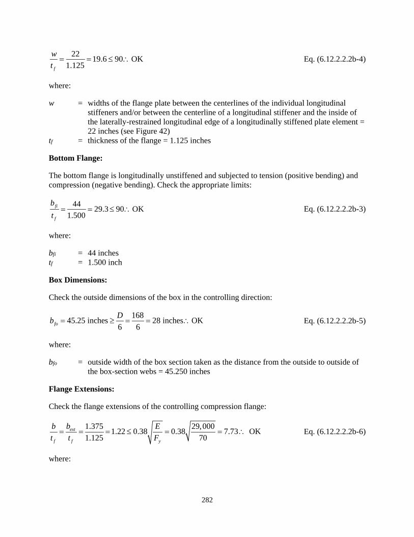
282
22 19.6 90 OK1.125f
wt
= = ≤ ∴ Eq. (6.12.2.2.2b-4)
where:
w = widths of the flange plate between the centerlines of the individual longitudinal stiffeners and/or between the centerline of a longitudinal stiffener and the inside of the laterally-restrained longitudinal edge of a longitudinally stiffened plate element = 22 inches (see Figure 42)
tf = thickness of the flange = 1.125 inches
Bottom Flange:
The bottom flange is longitudinally unstiffened and subjected to tension (positive bending) and compression (negative bending). Check the appropriate limits:
44 29.3 90 OK1.500
fi
f
bt
= = ≤ ∴ Eq. (6.12.2.2.2b-3)
where:
bfi = 44 inches tf = 1.500 inch
Box Dimensions:
Check the outside dimensions of the box in the controlling direction:
168 28 inches OK6
45.25 inches6fo
Db = ≥ = = ∴ Eq. (6.12.2.2.2b-5)
where:
bfo = outside width of the box section taken as the distance from the outside to outside of the box-section webs = 45.250 inches
Flange Extensions:
Check the flange extensions of the controlling compression flange:
1.375 29,0001.22 0.38 0.38 7.73 OK1.125 70
ext
f f y
bb Et t F
= = = ≤ = = ∴ Eq. (6.12.2.2.2b-6)
where:

283
b = clear projecting width of the compression flange under consideration measured from the outside surface of the web = 1.375 inches
tf = minimum flange thickness = 1.125 inches
Stiffeners:
Article 6.12.2.2.2b requires that longitudinal stiffeners for compression flanges satisfy the requirements of Article E6.1.4 and that transverse stiffeners satisfy Article E6.1.5. These requirements were checked in Sections B.3.6.2.6 and B.3.6.2.8, respectively.
Minimum Plate Thickness:
Article 6.12.2.2.2b specifies that the thickness of compression and tension flanges corresponding to the box section principal axis subjected to the larger bending moment should not be less than the thickness of the webs. For the tie girder, the bending about the x-axis is the dominant direction. The flanges (1.125 and 1.500 inches) are thicker than the webs (0.625 inches). Additionally, the thickness of the compression and tension flanges is not to be less than 0.500 inches. The thickness of the flanges about both axes of bending exceed this limit.
Finally, the discussion in Section 3.2.2.2 for flexure suggests a minimum plate thickness of 0.75 inches for flange plates subjected to significant bending stresses. These recommendations are intended to ensure robustness of the member response; to facilitate handling; and to minimize distortion and possible cupping of the plates during welding. The minimum plate thickness of the cross-section (web thickness equal to 0.625 inches) is less than this suggested minimum thickness limit.
B.3.6.4.2 Classification of Sections
Articles 6.12.2.2.2c and 6.12.2.2.2d define the web plastification factor for the compression flange, Rpc, the web load-shedding factor, Rb, and the compression-flange slenderness factor, Rf, based on web and compression flange slenderness values for longitudinally unstiffened and longitudinally stiffened compression flanges, respectively. For negative bending, the unstiffened bottom flange is in compression; therefore, Article 6.12.2.2.2c applies [F2]. For positive bending, the stiffened top flange is in compression;, therefore, Article 6.12.2.2.2d applies [F2]. Compute the corresponding values of Rpc, Rb and Rf for negative and positive bending below.
Prior to computing these values, check the shear lag requirements at the strength limit state. Sections where the effective span, Leff, is less than five times the flange width measured between the inside faces of the webs, bfi, must have a reduction factor applied to the effective flange area, which is defined as bet of a longitudinally unstiffened compression flange, where be is determined as specified in Article 6.9.4.2.2b with Fcr taken equal to Fy; or to the effective area, Aeff, of a longitudinally stiffened compression flange determined as specified in Article 6.12.2.2.2d; or to the gross area of the tension flange including any longitudinal stiffeners.
Check if the effective span length of the member, Leff, is greater than five times the flange width between web plates, bfi, to prevent shear lag effects from reducing the effective flange width per Article 6.12.2.2.2g [F2C and F4]:
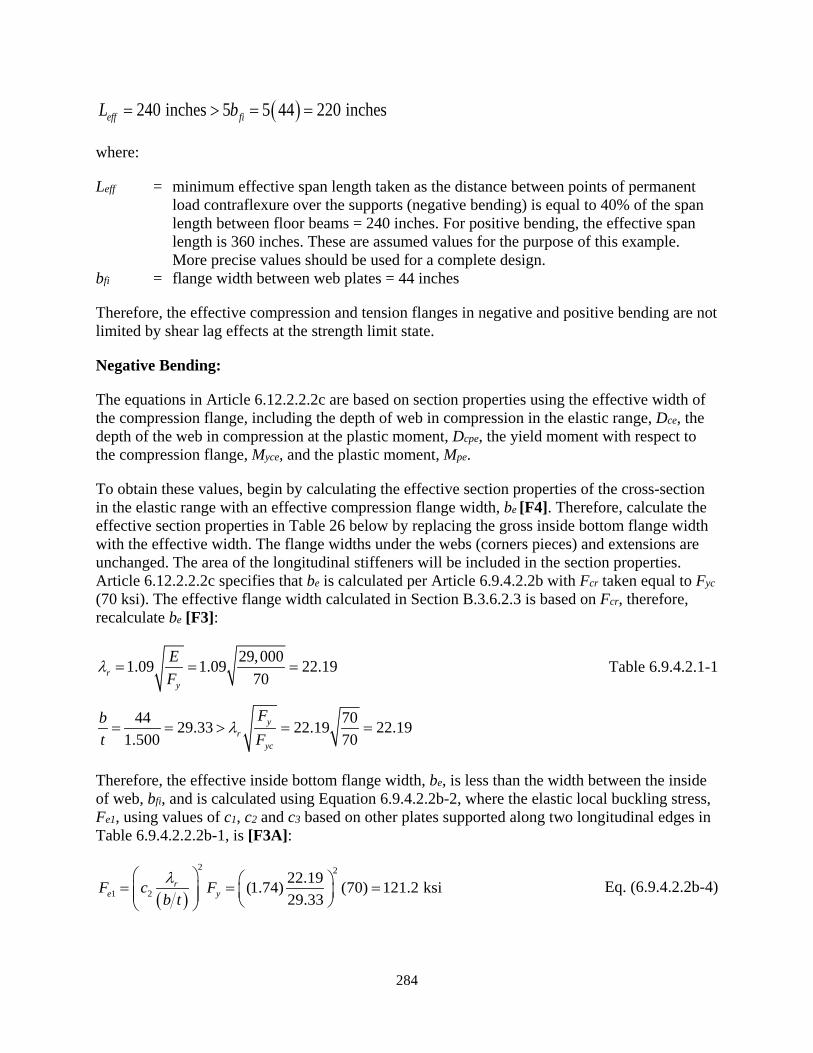
284
( )240 inches 5 5 44 220 incheseff fiL b= > = =
where:
Leff = minimum effective span length taken as the distance between points of permanent load contraflexure over the supports (negative bending) is equal to 40% of the span length between floor beams = 240 inches. For positive bending, the effective span length is 360 inches. These are assumed values for the purpose of this example. More precise values should be used for a complete design.
bfi = flange width between web plates = 44 inches
Therefore, the effective compression and tension flanges in negative and positive bending are not limited by shear lag effects at the strength limit state.
Negative Bending:
The equations in Article 6.12.2.2.2c are based on section properties using the effective width of the compression flange, including the depth of web in compression in the elastic range, Dce, the depth of the web in compression at the plastic moment, Dcpe, the yield moment with respect to the compression flange, Myce, and the plastic moment, Mpe.
To obtain these values, begin by calculating the effective section properties of the cross-section in the elastic range with an effective compression flange width, be [F4]. Therefore, calculate the effective section properties in Table 26 below by replacing the gross inside bottom flange width with the effective width. The flange widths under the webs (corners pieces) and extensions are unchanged. The area of the longitudinal stiffeners will be included in the section properties. Article 6.12.2.2.2c specifies that be is calculated per Article 6.9.4.2.2b with Fcr taken equal to Fyc (70 ksi). The effective flange width calculated in Section B.3.6.2.3 is based on Fcr, therefore, recalculate be [F3]:
29,0001.09 1.09 22.1970r
y
EF
λ = = = Table 6.9.4.2.1-1
44 7029.33 22.19 22.191.500 70
yr
yc
Fbt F
λ= = > = =
Therefore, the effective inside bottom flange width, be, is less than the width between the inside of web, bfi, and is calculated using Equation 6.9.4.2.2b-2, where the elastic local buckling stress, Fe1, using values of c1, c2 and c3 based on other plates supported along two longitudinal edges in Table 6.9.4.2.2.2b-1, is [F3A]:
( )
2 2
1 222.19(1.74) (70) 121.2 ksi29.33
re yF c F
b tλ = = =
Eq. (6.9.4.2.2b-4)

285
1 11 31
121.2 121.244 1 0.22 0.075 37.84 inches70 70
e ee
yc yc
F Fb b c cF F
= − −
= − − =
Eq. (6.9.4.2.2b-2)
Table 26. X-axis negative bending effective cross-section properties including longitudinal stiffeners.
COMPONENT b (inch)
t (inch)
A (inch2)
dy,bot (inch)
Ady,bot (inch2)
d (inch)
Ad2 (inch3)
Io,x (inch4)
Ix (inch4)
Bottom Flange (Effective Width) 37.840 1.500 56.76 0.75 43 84.04 400,870 11 400,880
Bottom Flange (Corners and Extensions)
4.000 1.500 6.00 0.75 5 84.04 42,375 1 42,376
Left Web Plate 168.000 0.625 105.00 85.50 8,978 -0.71 53 246,960 247,013 Right Web Plate 168.000 0.625 105.00 85.50 8,978 -0.71 53 246,960 247,013 Top Flange 48.000 1.125 54.00 170.06 9,183 -85.27 392,666 6 392,671 Left Web Stiffener 1 8.000 1.000 8.00 57.50 460 27.29 5,957 1 5,958
Left Web Stiffener 2 8.000 1.000 8.00 113.50 908 -28.71 6,595 1 6,595
Right Web Stiffener 1 8.000 1.000 8.00 57.50 460 27.29 5,957 1 5,958
Right Web Stiffener 2 8.000 1.000 8.00 113.50 908 -28.71 6,595 1 6,595
Top Flange Stiffener 7.000 0.875 6.13 166.00 1,017 -81.21 40,396 25 40,421
Σ 364.89 30,938 1,395,482
where:
Fyc = specified minimum yield strength of the compression (bottom) flange = 70 ksi Fyt = specified minimum yield strength of the tension (top) flange = 70 ksi
41,395,482 inchxeI =
3
,
1,395,482 16,458 inch84.79
xexce
e bot
ISd
= = =
( )70 16,45896,007 kip-ft
12yce yc xceM F S= = =
, , 84.79 1.500 83.29 inchesce e bot f botD d t= − = − =
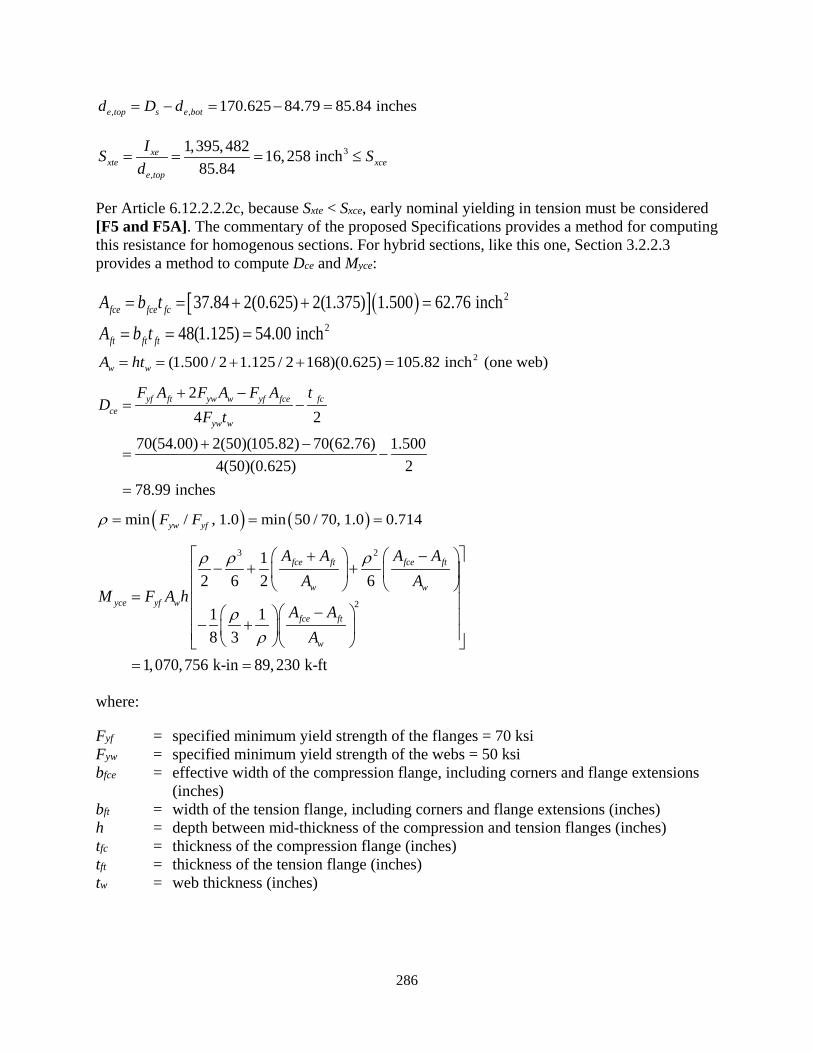
286
, , 170.625 84.79 85.84 inchese top s e botd D d= − = − =
3
,
1,395,482 16,258 inch85.84
xexte xce
e top
IS Sd
= = = ≤
Per Article 6.12.2.2.2c, because Sxte < Sxce, early nominal yielding in tension must be considered [F5 and F5A]. The commentary of the proposed Specifications provides a method for computing this resistance for homogenous sections. For hybrid sections, like this one, Section 3.2.2.3 provides a method to compute Dce and Myce:
[ ]( ) 237.84 2(0.625) 2(1.375) 1.500 62.76 inchfce fce fcA b t= = + + =248(1.125) 54.00 inchft ft ftA b t= = =
2(1.500 / 2 1.125 / 2 168)(0.625) 105.82 inch (one web)w wA ht= = + + =
24 2
70(54.00) 2(50)(105.82) 70(62.76) 1.5004(50)(0.625) 2
78.99 inches
yf ft yw w yf fce fcce
yw w
F A F A F A tD
F t+ −
= −
+ −= −
=
( ) ( )min / , 1.0 min 50 / 70, 1.0 0.714yw yfF Fρ = = =
3 2
2
12 6 2 6
1 18 3
1,070,756 k-in 89,230 k-ft
fce ft fce ft
w wyce yf w
fce ft
w
A A A AA A
M F A hA A
A
ρ ρ ρ
ρρ
+ − − + +
= − − + = =
where:
Fyf = specified minimum yield strength of the flanges = 70 ksi Fyw = specified minimum yield strength of the webs = 50 ksi bfce = effective width of the compression flange, including corners and flange extensions
(inches) bft = width of the tension flange, including corners and flange extensions (inches) h = depth between mid-thickness of the compression and tension flanges (inches) tfc = thickness of the compression flange (inches) tft = thickness of the tension flange (inches) tw = web thickness (inches)

287
With the effective section properties calculated, compute the web slenderness ratios per Article 6.12.2.2.2c [F7]. The depth of web in compression at the plastic moment for the effective section, Dcpe, is computed in Section B.3.6.4.4.
( )2 78.992 252.8 0.625
cew
w
Dt
λ = = = Eq. (6.12.2.2.2c-2)
29,0004.6 4.6 93.670rw
yc
EF
λ = = = Eq. (6.12.2.2.2c-6)
78.99 29,0003.1 3.1 63.0 93.679.09 70
cepw w
cpe yc
D ED F
λ λ = = = ≤ =
Eq. (6.12.2.2.2c-3)
w pwλ λ> [F8] Eq. (6.12.2.2.2c-1)
w rwλ λ> [F8A] Eq. (6.12.2.2.2c-8)
Therefore, the web is classified as slender per Equation 6.12.2.2.2c-8. Rpc is limited to the hybrid factor, Rh, which per Article 6.12.2.2.2c is taken as 1.0 when Myce is calculated using Section 3.2.2.3 for nominal yielding in tension [F8C].
Because the web is slender, the web load-shedding factor, Rb, is calculated per Article 6.10.1.10.2 as modified per Article 6.12.2.2.2c [F8C]. awc is to be determined with bfctfc taken as one-half of the effective flange area betfc/2 for noncompact flanges. Include the compact area of the flange under the web (corner) and the flange extensions in the area as well. Dc is to be taken as the depth of web in compression using the effective cross-section, Dce. Base the calculations on a noncomposite hybrid longitudinally-stiffened (i.e., longitudinal stiffeners on the web) section:
37.84 0.625 1.375 20.93 inches2 2e
fc w extbb t b= + + = + + =
( )( )( )
2 78.99 0.6252 3.1520.93 1.500
c wwc
fc fc
D tab t
= = = Eq. (6.10.1.10.2-8)
( )1 1 29,0005.7 5.7 123.4
2 2 78.99 168 70rwDc yc
ED D F
λ
= = = Eq. (6.10.1.10.2-7)
( )2 78.992 123.4 116.0168
crw rwD
DD
λ λ = = =
Eq. (6.10.1.10.2-4)
( )2 79.002 252.8 0.625
crw
w
Dt
λ= = > Eq. (6.10.1.10.2-1)
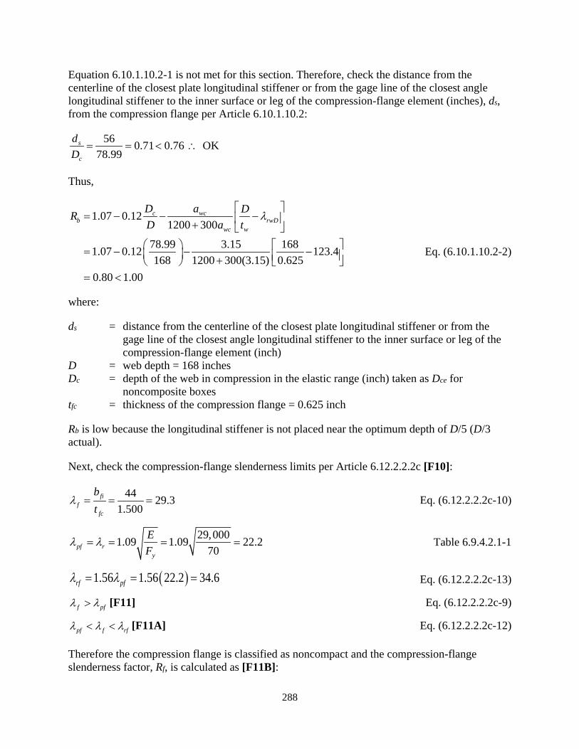
288
Equation 6.10.1.10.2-1 is not met for this section. Therefore, check the distance from the centerline of the closest plate longitudinal stiffener or from the gage line of the closest angle longitudinal stiffener to the inner surface or leg of the compression-flange element (inches), ds, from the compression flange per Article 6.10.1.10.2:
56 0.71 0.76 OK78.99
s
c
dD
= = < ∴
Thus,
1.07 0.121200 300
78.99 3.15 1681.07 0.12 123.4168 1200 300(3.15) 0.625
0.80 1.00
c wcb rwD
wc w
D a DRD a t
= − − − +
= − − − + = <
λ
Eq. (6.10.1.10.2-2)
where:
ds = distance from the centerline of the closest plate longitudinal stiffener or from the gage line of the closest angle longitudinal stiffener to the inner surface or leg of the compression-flange element (inch)
D = web depth = 168 inches Dc = depth of the web in compression in the elastic range (inch) taken as Dce for
noncomposite boxes tfc = thickness of the compression flange = 0.625 inch
Rb is low because the longitudinal stiffener is not placed near the optimum depth of D/5 (D/3 actual).
Next, check the compression-flange slenderness limits per Article 6.12.2.2.2c [F10]:
44 29.31.500
fif
fc
bt
λ = = = Eq. (6.12.2.2.2c-10)
29,0001.09 1.09 22.270pf r
y
EF
λ λ= = = = Table 6.9.4.2.1-1
( )1.56 1.56 34.622.2rf pfλ λ= = = Eq. (6.12.2.2.2c-13)
f pfλ λ> [F11] Eq. (6.12.2.2.2c-9)
pf f rfλ λ λ< < [F11A] Eq. (6.12.2.2.2c-12)
Therefore the compression flange is classified as noncompact and the compression-flange slenderness factor, Rf, is calculated as [F11B]:

289
29.3 22.21 0.15 1 0.15 0.91 1.034.6 22.2
f pff
rf pf
Rλ λλ λ
− − = − = − = ≤ − − Eq. (6.12.2.2.2c-14)
With Rpc, Rb and Rf calculated, the nominal flexural resistance in negative bending about the x-axis can be calculated in the next Section (B.3.6.4.3) per Article 6.12.2.2.2e.
The compression flange is unstiffened for negative bending; therefore, no checks are required for longitudinal stiffeners [F2I] or transverse stiffeners [F2J] resisting compression forces.
Positive Bending:
The equations in Article 6.12.2.2.2d are based on section properties using the effective area of the longitudinally stiffened compression flange [F2], including the depth of web in compression in the elastic range, Dce, the depth of the web in compression at the plastic moment, Dcpe, the yield moment with respect to the compression flange, Myce, and the plastic moment, Mpe.
To obtain these values, begin by calculating the effective section properties of the cross-section in the elastic range with an effective compression (top) flange area, Aeff, equal to 52.26 inch2 as computed in Section B.3.6.2.4 per Article E6.1.3 located at the centroid of the gross area of the entire stiffened plate and its longitudinal stiffeners [F2A and F2B]. Calculate the distance of the stiffened plate centroid from the bottom of the section:
244(1.125) 7(0.875) 55.63 inchsp fi f s sA b t b t= + = + =
( ),
/ 2 ( / 2)
44(1.125)(1.125 / 2) (7)(0.875)(1.125 7 / 2)170.62555.63
169.62 inches
fi f f s s f se sp s
sp
b t t b t t bd D
A
+ + = −
+ + = −
=
where:
bfi = inside width of stiffened top flange plate = 44 inches tf = thickness of top flange plate = 1.125 inches bs = width of top flange stiffener = 7 inches ts = thickness of top flange stiffener = 0.875 inches Asp = total area of stiffened plate (inch2) de,sp = distance from bottom of cross-section to centroid of stiffened plate gross area
(inches)
Calculate the effective section properties in Table 27 by replacing the top flange between the webs and associated longitudinal stiffener with the effective area at the location, de,sp, calculated above [F2C]. The flange widths above the webs (corners pieces) and extensions are unchanged. Per Section 3.2.2.3, the area of the web longitudinal stiffeners will be included in the section
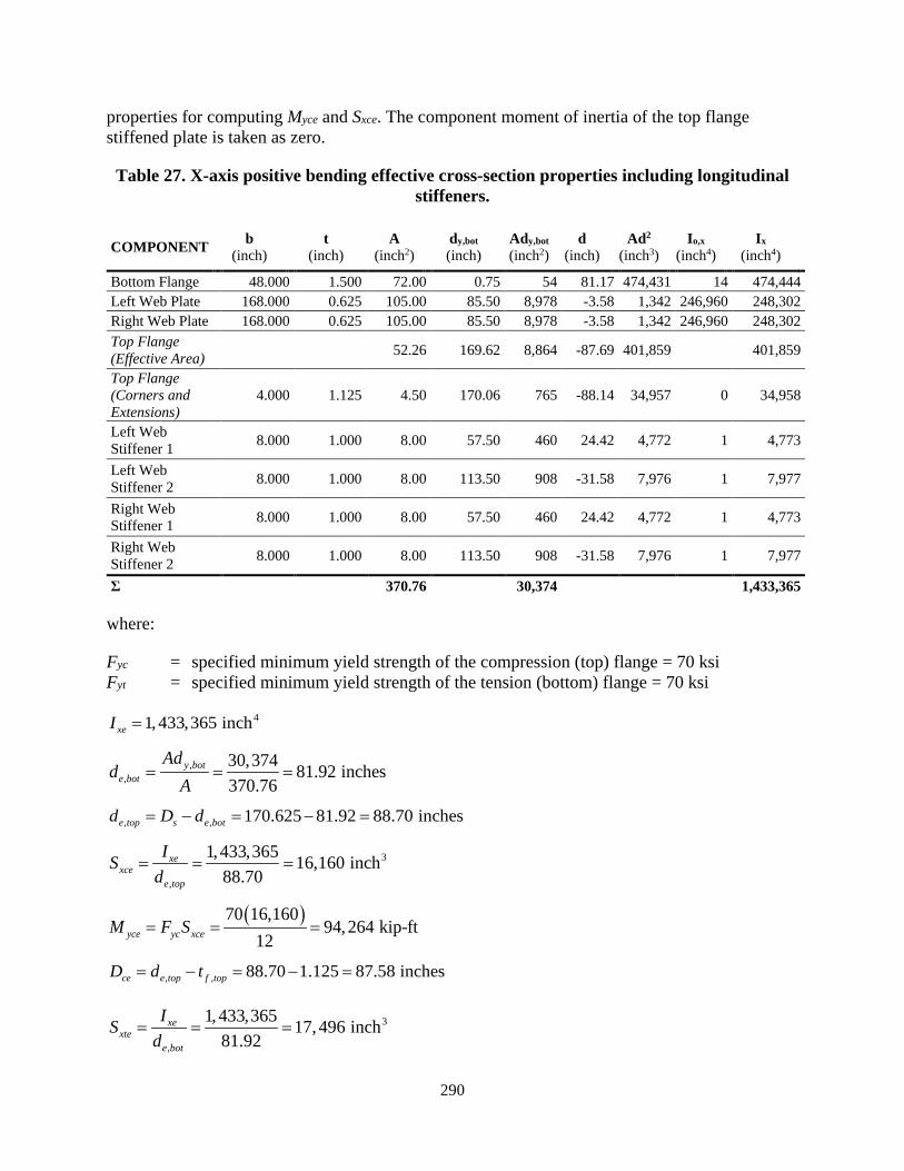
290
properties for computing Myce and Sxce. The component moment of inertia of the top flange stiffened plate is taken as zero.
Table 27. X-axis positive bending effective cross-section properties including longitudinal stiffeners.
COMPONENT b (inch)
t (inch)
A (inch2)
dy,bot (inch)
Ady,bot (inch2)
d (inch)
Ad2 (inch3)
Io,x (inch4)
Ix (inch4)
Bottom Flange 48.000 1.500 72.00 0.75 54 81.17 474,431 14 474,444 Left Web Plate 168.000 0.625 105.00 85.50 8,978 -3.58 1,342 246,960 248,302 Right Web Plate 168.000 0.625 105.00 85.50 8,978 -3.58 1,342 246,960 248,302 Top Flange (Effective Area)
52.26 169.62 8,864 -87.69 401,859 401,859
Top Flange (Corners and Extensions)
4.000 1.125 4.50 170.06 765 -88.14 34,957 0 34,958
Left Web Stiffener 1 8.000 1.000 8.00 57.50 460 24.42 4,772 1 4,773
Left Web Stiffener 2 8.000 1.000 8.00 113.50 908 -31.58 7,976 1 7,977
Right Web Stiffener 1 8.000 1.000 8.00 57.50 460 24.42 4,772 1 4,773
Right Web Stiffener 2 8.000 1.000 8.00 113.50 908 -31.58 7,976 1 7,977
Σ 370.76 30,374 1,433,365
where:
Fyc = specified minimum yield strength of the compression (top) flange = 70 ksi Fyt = specified minimum yield strength of the tension (bottom) flange = 70 ksi
41, 433,365 inchxeI =
,,
30,374 81.92 inches370.76
y bote bot
Add
A= = =
, , 170.625 81.92 88.70 inchese top s e botd D d= − = − =
3
,
1, 433,365 16,160 inch88.70
xexce
e top
ISd
= = =
( )70 16,16094,264 kip-ft
12yce yc xceM F S= = =
, , 88.70 1.125 87.58 inchesce e top f topD d t= − = − =
3
,
1, 433,365 17,496 inch81.92
xexte
e bot
ISd
= = =
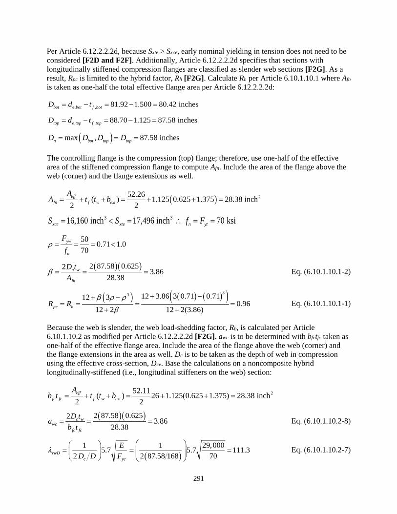
291
Per Article 6.12.2.2.2d, because Sxte > Sxce, early nominal yielding in tension does not need to be considered [F2D and F2F]. Additionally, Article 6.12.2.2.2d specifies that sections with longitudinally stiffened compression flanges are classified as slender web sections [F2G]. As a result, Rpc is limited to the hybrid factor, Rh [F2G]. Calculate Rh per Article 6.10.1.10.1 where Afn is taken as one-half the total effective flange area per Article 6.12.2.2.2d:
, , 81.92 1.500 80.42 inchesbot e bot f botD d t= − = − =
, , 88.70 1.125 87.58 inchestop e top f topD d t= − = − =
( )max , 87.58 inchesn bot top topD D D D= = =
The controlling flange is the compression (top) flange; therefore, use one-half of the effective area of the stiffened compression flange to compute Afn. Include the area of the flange above the web (corner) and the flange extensions as well.
( ) 252.26( ) 1.125 0.625 1.375 28.38 inch2 2eff
fn f w ext
AA t t b= + + = + + =
3 316,160 inch 17,496 inch 70 ksixce xte n ytS S f F= < = ∴ = =
50 0.71 1.070
yw
n
Ff
ρ = = = <
( )( )2 87.58 0.6252 3.8628.38
n w
fn
D tA
β = = = Eq. (6.10.1.10.1-2)
( ) ( ) ( )( )33 12 3.86 3 0.71 0.7112 30.96
12 2 12 2(3.86)pc hR Rβ ρ ρ
β
+ −+ −= = = =
+ + Eq. (6.10.1.10.1-1)
Because the web is slender, the web load-shedding factor, Rb, is calculated per Article 6.10.1.10.2 as modified per Article 6.12.2.2.2d [F2G]. awc is to be determined with bfctfc taken as one-half of the effective flange area. Include the area of the flange above the web (corner) and the flange extensions in the area as well. Dc is to be taken as the depth of web in compression using the effective cross-section, Dce. Base the calculations on a noncomposite hybrid longitudinally-stiffened (i.e., longitudinal stiffeners on the web) section:
252.11( ) 26 1.125(0.625 1.375) 28.38 inch2 2eff
fc fc f w ext
Ab t t t b= + + = + + =
( )( )2 87.58 0.6252 3.8628.38
c wwc
fc fc
D tab t
= = = Eq. (6.10.1.10.2-8)
( )1 1 29,0005.7 5.7 111.3
2 2 87.58 168 70rwDc yc
ED D F
λ
= = = Eq. (6.10.1.10.2-7)
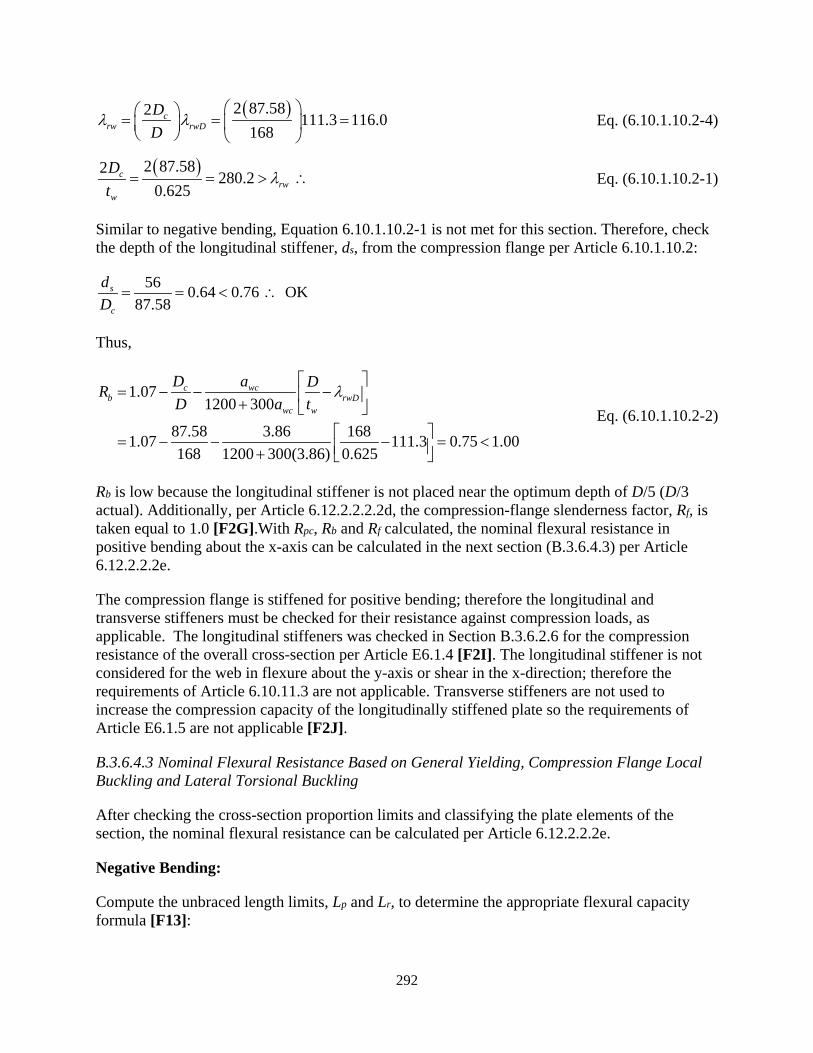
292
( )2 87.582 111.3 116.0168
crw rwD
DD
λ λ = = =
Eq. (6.10.1.10.2-4)
( )2 87.582 280.2 0.625
crw
w
Dt
λ= = > ∴ Eq. (6.10.1.10.2-1)
Similar to negative bending, Equation 6.10.1.10.2-1 is not met for this section. Therefore, check the depth of the longitudinal stiffener, ds, from the compression flange per Article 6.10.1.10.2:
56 0.64 0.76 OK87.58
s
c
dD
= = < ∴
Thus,
1.071200 300
87.58 3.86 1681.07 111.3 0.75 1.00168 1200 300(3.86) 0.625
c wcb rwD
wc w
D a DRD a t
= − − − +
= − − − = < +
λ Eq. (6.10.1.10.2-2)
Rb is low because the longitudinal stiffener is not placed near the optimum depth of D/5 (D/3 actual). Additionally, per Article 6.12.2.2.2.2d, the compression-flange slenderness factor, Rf, is taken equal to 1.0 [F2G].With Rpc, Rb and Rf calculated, the nominal flexural resistance in positive bending about the x-axis can be calculated in the next section (B.3.6.4.3) per Article 6.12.2.2.2e.
The compression flange is stiffened for positive bending; therefore the longitudinal and transverse stiffeners must be checked for their resistance against compression loads, as applicable. The longitudinal stiffeners was checked in Section B.3.6.2.6 for the compression resistance of the overall cross-section per Article E6.1.4 [F2I]. The longitudinal stiffener is not considered for the web in flexure about the y-axis or shear in the x-direction; therefore the requirements of Article 6.10.11.3 are not applicable. Transverse stiffeners are not used to increase the compression capacity of the longitudinally stiffened plate so the requirements of Article E6.1.5 are not applicable [F2J].
B.3.6.4.3 Nominal Flexural Resistance Based on General Yielding, Compression Flange Local Buckling and Lateral Torsional Buckling
After checking the cross-section proportion limits and classifying the plate elements of the section, the nominal flexural resistance can be calculated per Article 6.12.2.2.2e.
Negative Bending:
Compute the unbraced length limits, Lp and Lr, to determine the appropriate flexural capacity formula [F13]:
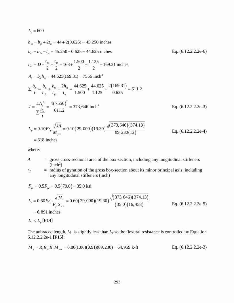
293
600bL =
2 44 2(0.625) 45.250 inchesfo fi wb b t= + = + =
45.250 0.625 44.625 inchesm fo wb b t= − = − = Eq. (6.12.2.2.2e-6)
1.500 1.125168 169.31 inches2 2 2 2fc ft
m
t th D= + + = + + =
244.625(169.31) 7556 inchm moA b h= = =
( )2 169.312 44.625 44.625 611.21.500 1.125 0.625
m m m m
fc ft w
b b b ht t t t
∑ = + + = + + =
( )224
614 75564 373,646
. i
1 2ncho
m
AJ bt
= = =∑
Eq. (6.12.2.2.2e-3)
( )( ) ( )( )( )
373,646 374.130.10 0.10 29,000 19.30
89,230 12618 inches
p yyce
JAL ErM
= =
=
Eq. (6.12.2.2.2e-4)
where:
A = gross cross-sectional area of the box-section, including any longitudinal stiffeners (inch2)
ry = radius of gyration of the gross box-section about its minor principal axis, including any longitudinal stiffeners (inch)
( )0.5 0.5 70.0 35.0 ksiyr ycF F= = =
( )( ) ( )( )( )( )373,646 374.13
0.60 0.60 29,000 19.3035.0 16,458
6,891 inches
r yyr xce
JAL ErF S
= =
=
Eq. (6.12.2.2.2e-5)
b pL L< [F14]
The unbraced length, Lb, is slightly less than Lp so the flexural resistance is controlled by Equation 6.12.2.2.2e-1 [F15]:
0.80(1.00)(0.91)(89,230) 64,959 k-ftn b pc f yceM R R R M= = = Eq. (6.12.2.2.2e-2)

294
Positive Bending:
Compute the unbraced length limits, Lp and Lr, to determine the appropriate flexural capacity formula [F13]. The St. Venant torsional constant, J, is the same for positive and negative bending.
600bL =
( )( ) ( )( )( )
0.10
373,646 374.130.10 29,000 19.30 585 inches
94,264 12
p yyce
JAL ErM
=
= =
Eq. (6.12.2.2.2e-4)
( )( ) ( )( )( )( )
0.60
373,646 374.130.60 29,000 19.30 7,018 inches
35.0 16,160
r yyr xce
JAL ErF S
=
= =
Eq. (6.12.2.2.2e-5)
b pL L> [F14]
The unbraced length, Lb, is slightly over Lp so the flexural resistance is controlled by Equation 6.12.2.2.2e-2 [F14A]. For positive bending in the tie girder, conservatively assume the moment gradient modifier, Cb, is 1.0:
( )
( )
0.96(1.00)(94,264)1.0(0.75) 16,160 600 5850.96(1.00) 94,264 35
12 7,018 58567,794 k-ft
0.75(0.96)(1.00
b pn b b pc f yce pc f yce yr xce
r p
b pc f yce
L LM C R R R M R R M F S
L L
R R R M
−= − − −
= − − − −
=≤ = )(94,264) 67,870 k-ft=
Eq. (6.12.2.2.2e-2)
B.3.6.4.4 Nominal Plastic Moment Flexural Resistance
The tie girder is in tension; therefore, the alternative combined axial tension and flexure interaction relationships in Article 6.8.2.3.1 are applicable. The previously calculated flexural resistances based on general yielding, compression flange local buckling and lateral torsional buckling covers the interaction effects of the compression flange using Equation 6.8.2.3.1-4, which conservatively ignores the beneficial effects of axial tension by checking interaction of biaxial flexure only.

295
To ensure the tension flange capacity of the cross-section is not exceed, the ratio of factored axial load to axial yield capacity must be combined with the ratios of factored biaxial moments to factored plastic moment resistance, Mrpe about each axis for use in Equation 6.8.2.3.1-3 [F17H]. Therefore, per Article 6.8.2.3.1, compute the plastic moment, Mxpe, about the x-axis neglecting any web longitudinal stiffeners while using the effective compression flange area per Articles 6.12.2.2.2c and 6.12.2.2.2d, as applicable. Additionally, consider any reductions in flange width or area for strength limit shear lag effects to both compression and tension flanges, as applicable. The section is asymmetric for x-axis flexure, therefore, the plastic moment flexural resistance must be calculated for negative and positive bending:
Negative Bending:
Calculate the plastic moment, Mxpe,neg, using Case I in Table D6.1-2 for negative moment with deck reinforcement parameters set to zero. The nomenclature assumes the bottom flange and lower portion of the web are in compression. The compression flange is longitudinally unstiffened and slender. The effective width, be, can be found in Table 26, which must be added to the corner and extension widths of the bottom flange. Additionally, for negative bending, the flanges are not subjected to any shear lag reductions.
( )( )( )(2 2 )
70.0 2(1.375) 2(0.625) 37.84 1.500 4,394 kipsc yc c c yc ext w e cP F b t F b t b t= = + +
= + + =
( )( )( )70.0 48.000 1.125 3,780 kipst yt t tP F b t= = =
( ) ( )( )( )( )2 50.0 168 2 0.625 10,500 kipsw yw wP F D t= = =
168 4,394 3,7801 1 88.91 inches2 2 10,500
c t
w
P PDYP
− − = + = + = Table D6.1-2 Case I
( ) ( ) 1.500168 88.91 79.84 inches2 2c
ctd D Y= − + = − + =
1.12588.91 89.47 inches2 2t
ttd Y= + = + =
( ) [ ]
( ) ( ) ( )
( )( ) ( )( )
22,
2 2168 88.91
t
210,500 88.912 168 /12
3,780 89.47 4,394 79.84
94,293 kips-f
wxpe neg t t c c
PM Y D Y Pd P dD = + − + +
+ = + +
−
=
Table D6.1-2 Case I
168 88.91 79.09 inchescpeD D Y= − = − =
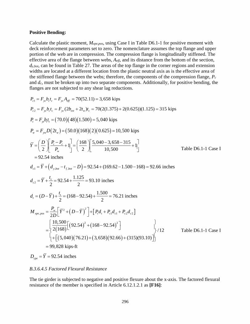
296
Positive Bending:
Calculate the plastic moment, Mxpe,pos, using Case I in Table D6.1-1 for positive moment with deck reinforcement parameters set to zero. The nomenclature assumes the top flange and upper portion of the web are in compression. The compression flange is longitudinally stiffened. The effective area of the flange between webs, Aeff, and its distance from the bottom of the section, dy,bot, can be found in Table 27. The areas of the top flange in the corner regions and extension widths are located at a different location from the plastic neutral axis as is the effective area of the stiffened flange between the webs; therefore, the components of the compression flange, Pc and dc, must be broken up into two separate components. Additionally, for positive bending, the flanges are not subjected to any shear lag reductions.
1 70(52.11) 3,658 kipsc yc c c yc effP F b t F A= = = =
2 (2 2 ) 70(2(1.375) 2(0.625))(1.125) 315 kipsc yc c c yc ext w cP F b t F b t t= = + = + =
( )( )( )70.0 48 1.500 5,040 kipst yt t tP F b t= = =
( ) ( )( )( )( )2 50.0 168 2 0.625 10,500 kipsw yw wP F D t= = =
168 5,040 3,658 3151 12 2 10,500
92.54 inchesw
ctP PDYP
− − − = + = + =
Table D6.1-1 Case I
( )1 , , 92.54 (169.62 1.500 168) 92.66 inchesc y bot f botd Y d t D= + − − = + − − =
21.12592.54 93.10 inches
2 2c
ctd Y= + = + =
1.500( ) (168 92.54) 76.21 inches2 2t
ttd D Y= − + = − + =
( ) [ ]
( ) ( ) ( )
( )( ) ( )( )
22, 1 1
2 2
2 2210,500 92.542 168 /12
5,040 76.21 3,658 92.66 (315)(93.10)
99,828 kips-ft
168 92.54
wxpe pos t t c c cc
PM P PY D Y Pd dD
d = + − + +
+ = + + +
−
=
+
Table D6.1-1 Case I
92.54 inchescpeD Y= =
B.3.6.4.5 Factored Flexural Resistance
The tie girder is subjected to negative and positive flexure about the x-axis. The factored flexural resistance of the member is specified in Article 6.12.1.2.1 as [F16]:
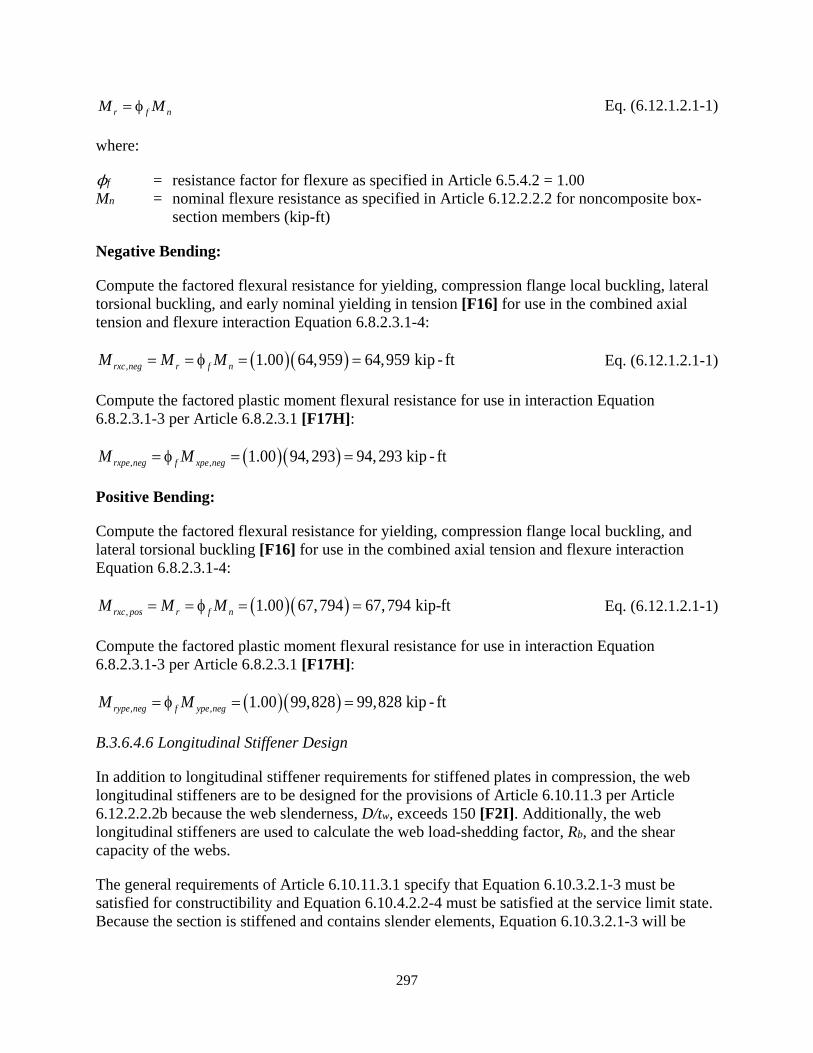
297
r f nM M= φ Eq. (6.12.1.2.1-1)
where:
ϕf = resistance factor for flexure as specified in Article 6.5.4.2 = 1.00 Mn = nominal flexure resistance as specified in Article 6.12.2.2.2 for noncomposite box-
section members (kip-ft)
Negative Bending:
Compute the factored flexural resistance for yielding, compression flange local buckling, lateral torsional buckling, and early nominal yielding in tension [F16] for use in the combined axial tension and flexure interaction Equation 6.8.2.3.1-4:
( )( ), 1.00 64,959 64,959 kip - ftrxc neg r f nM M M= = φ = = Eq. (6.12.1.2.1-1)
Compute the factored plastic moment flexural resistance for use in interaction Equation 6.8.2.3.1-3 per Article 6.8.2.3.1 [F17H]:
( )( ), , 1.00 94,293 94,293 kip - ftrxpe neg f xpe negM M= φ = =
Positive Bending:
Compute the factored flexural resistance for yielding, compression flange local buckling, and lateral torsional buckling [F16] for use in the combined axial tension and flexure interaction Equation 6.8.2.3.1-4:
( )( ), 1.00 67,794 67,794 kip-ftrxc pos fr nM M M= = φ = = Eq. (6.12.1.2.1-1)
Compute the factored plastic moment flexural resistance for use in interaction Equation 6.8.2.3.1-3 per Article 6.8.2.3.1 [F17H]:
( )( ), , 1.00 99,828 99,828 kip - ftrype neg f ype negM M= φ = =
B.3.6.4.6 Longitudinal Stiffener Design
In addition to longitudinal stiffener requirements for stiffened plates in compression, the web longitudinal stiffeners are to be designed for the provisions of Article 6.10.11.3 per Article 6.12.2.2.2b because the web slenderness, D/tw, exceeds 150 [F2I]. Additionally, the web longitudinal stiffeners are used to calculate the web load-shedding factor, Rb, and the shear capacity of the webs.
The general requirements of Article 6.10.11.3.1 specify that Equation 6.10.3.2.1-3 must be satisfied for constructibility and Equation 6.10.4.2.2-4 must be satisfied at the service limit state. Because the section is stiffened and contains slender elements, Equation 6.10.3.2.1-3 will be
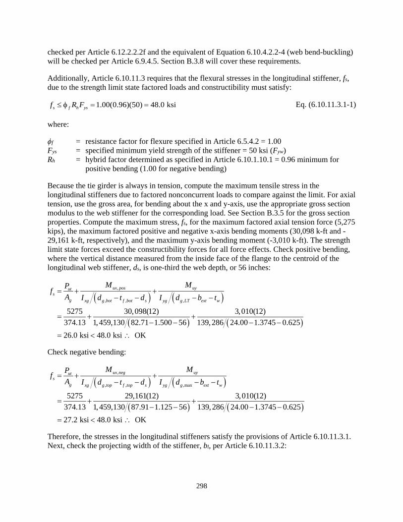
298
checked per Article 6.12.2.2.2f and the equivalent of Equation 6.10.4.2.2-4 (web bend-buckling) will be checked per Article 6.9.4.5. Section B.3.8 will cover these requirements.
Additionally, Article 6.10.11.3 requires that the flexural stresses in the longitudinal stiffener, fs, due to the strength limit state factored loads and constructibility must satisfy:
1.00(0.96)(50) 48.0 ksis f h ysf R F≤ φ = = Eq. (6.10.11.3.1-1)
where:
ϕf = resistance factor for flexure specified in Article 6.5.4.2 = 1.00 Fys = specified minimum yield strength of the stiffener = 50 ksi (Fyw) Rh = hybrid factor determined as specified in Article 6.10.1.10.1 = 0.96 minimum for
positive bending (1.00 for negative bending)
Because the tie girder is always in tension, compute the maximum tensile stress in the longitudinal stiffeners due to factored nonconcurrent loads to compare against the limit. For axial tension, use the gross area, for bending about the x and y-axis, use the appropriate gross section modulus to the web stiffener for the corresponding load. See Section B.3.5 for the gross section properties. Compute the maximum stress, fs, for the maximum factored axial tension force (5,275 kips), the maximum factored positive and negative x-axis bending moments (30,098 k-ft and -29,161 k-ft, respectively), and the maximum y-axis bending moment (-3,010 k-ft). The strength limit state forces exceed the constructibility forces for all force effects. Check positive bending, where the vertical distance measured from the inside face of the flange to the centroid of the longitudinal web stiffener, ds, is one-third the web depth, or 56 inches:
( ) ( )
( ) ( )
,
, , ,
5275 30,098(12) 3,010(12)374.13 1,459,130 82.71 1.500 56 139,286 24.00 1.3745 0.62526.0 ksi 48.0 ksi OK
ux pos uyuts
g xg g bot f bot s yg g LT ext w
M MPfA I d t d I d b t
= + +− − − −
= + +− − − −
= < ∴
Check negative bending:
( ) ( )
( ) ( )
,
, , ,max
5275 29,161(12) 3,010(12)374.13 1,459,130 87.91 1.125 56 139,286 24.00 1.3745 0.62527.2 ksi 48.0 ksi OK
ux neg uyuts
g xg g top f top s yg g ext w
M MPfA I d t d I d b t
= + +− − − −
= + +− − − −
= < ∴
Therefore, the stresses in the longitudinal stiffeners satisfy the provisions of Article 6.10.11.3.1. Next, check the projecting width of the stiffener, bl, per Article 6.10.11.3.2:
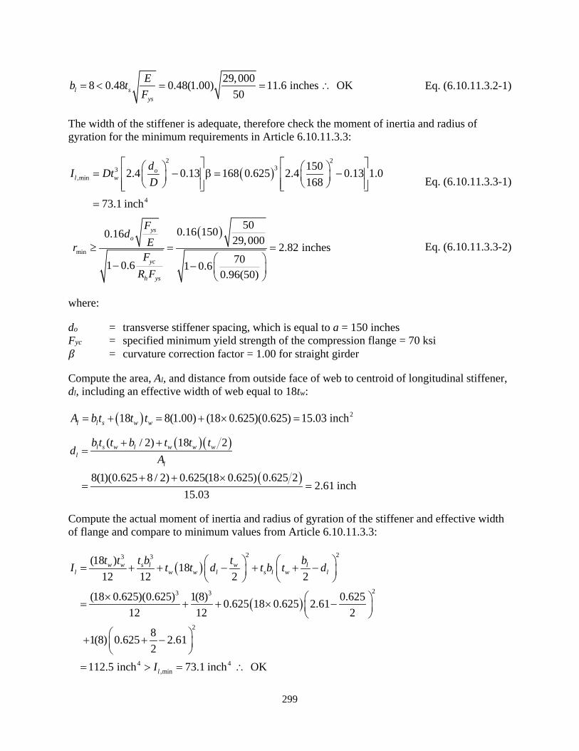
299
29,0008 0.48 0.48(1.00) 11.6 inches OK50l s
ys
Eb tF
= < = = ∴ Eq. (6.10.11.3.2-1)
The width of the stiffener is adequate, therefore check the moment of inertia and radius of gyration for the minimum requirements in Article 6.10.11.3.3:
( )2 2
33,min
4
1502.4 0.13 168 0.625 2.4 0.13 1.0168
73.1 inch
ol w
dI DtD
= − β = −
=
Eq. (6.10.11.3.3-1)
( )
min
500.16 1500.16 29,000 2.82 inches701 0.6 1 0.6
0.96(50)
yso
yc
h ys
Fd
ErF
R F
≥ = = − −
Eq. (6.10.11.3.3-2)
where:
do = transverse stiffener spacing, which is equal to a = 150 inches Fyc = specified minimum yield strength of the compression flange = 70 ksi 𝛽𝛽 = curvature correction factor = 1.00 for straight girder
Compute the area, Al, and distance from outside face of web to centroid of longitudinal stiffener, dl, including an effective width of web equal to 18tw:
( ) 218 8(1.00) (18 0.625)(0.625) 15.03 inchl l s w wA b t t t= + = + × =
( )( )
( )
( / 2) 18 2
8(1)(0.625 8 / 2) 0.625(18 0.625) 0.625 22.61 inch
15.03
l s w l w w wl
l
b t t b t t td
A+ +
=
+ + ×= =
Compute the actual moment of inertia and radius of gyration of the stiffener and effective width of flange and compare to minimum values from Article 6.10.11.3.3:
( )
( )
2 23 3
23 3
2
4 4,min
(18 ) 1812 12 2 2
(18 0.625)(0.625) 1(8) 0.6250.625 18 0.625 2.6112 12 2
81(8) 0.625 2.612
112.5 inch 73.1 inch OK
w w s l w ll w w l s l w l
l
t t t b t bI t t d t b t d
I
= + + − + + −
× = + + × −
+ + −
= > = ∴

300
,min112.5 2.74 inches 2.82 inches NG15.03
ll l
l
Ir rA
= = = < = ∴
Therefore, the stiffener dimensions are OK for moment of inertia but are not adequate for the radius of gyration requirement. However, minimally increasing the stiffener width to 8.250 inches will satisfy the radius of gyration requirements. As a result, detail a wider stiffener (e.g. 8.500 inches) while maintaining the slenderness requirement of Equation E6.1.4-1. Continue these calculations using an 8-inch by 1-inch stiffener. It should be noted that using a transverse stiffener spacing, do, equal to the diaphragm spacing (300 inches), which is approaching 2D, would have resulted in extremely large moment of inertia and radius of gyration requirements.
B.3.6.4.7 Transverse Stiffener Design
The web longitudinal stiffeners are designed to be effective for web flexure and shear per Article 6.10.11.3. Therefore, in addition to the transverse stiffener requirements for stiffened plates in compression, the stiffeners must be designed to satisfy the requirements of Article 6.10.11.1 for transverse stiffeners resisting shear [F2J].
Article 6.10.11.1.1 requires a maximum spacing of 2D for transverse stiffeners in web panels with longitudinal stiffeners. The transverse stiffener spacing, do, is 150 inches, which is less than 2D (336 inches) and therefore adequate. In addition to this, the transverse stiffeners must satisfy the dimensional and stiffness requirements of Articles 6.10.11.1.2 and 6.10.11.1.3. These will be checked when the web plates are checked for shear in Section B.3.6.6.
B.3.6.5 Y-axis Flexure
The tie girder is subjected to flexure about the y-axis. Determine the factored flexural resistance per Article 6.12. As discussed in the section for x-axis flexure, Article 6.12.2.2.2a specifies a number of general requirements. Those varying for flexure about the y-axis include:
• Flexural resistance is to be calculated per Article 6.12.2.2.2e for the combined influence of general yielding, compression flange local buckling, and/or lateral torsional buckling. The section is symmetrical about the y-axis, therefore the flexural resistance is the same for positive and negative bending about the y-axis.
• For flexure about the y-axis, the web plates act as the flanges and the flange plates act as the webs for Article 6.12.2.2.2. Because the web plates (for y-axis flexure) are different thicknesses, compute all section properties using the minimum web thickness (1.125 inches) for both webs per Article 6.12.2.2.2a. Also, because only the top flange, which is acting as a web, is stiffened, ignore the longitudinal stiffener for all y-axis flexure section properties per Article 6.12.2.2.2d.
Additionally, because the cross-section is a hybrid section with higher strength webs than both flanges for bending about the y-axis, calculate the limiting design yield strength of the web, Fyw,d, per Article 6.10.1.3 prior to computing the flexural and shear resistances:
( ), ,1.20min 1.20(50.0) 60.0 ksi 70.0 ksiyw d yc yt ywF F F F= = = < =
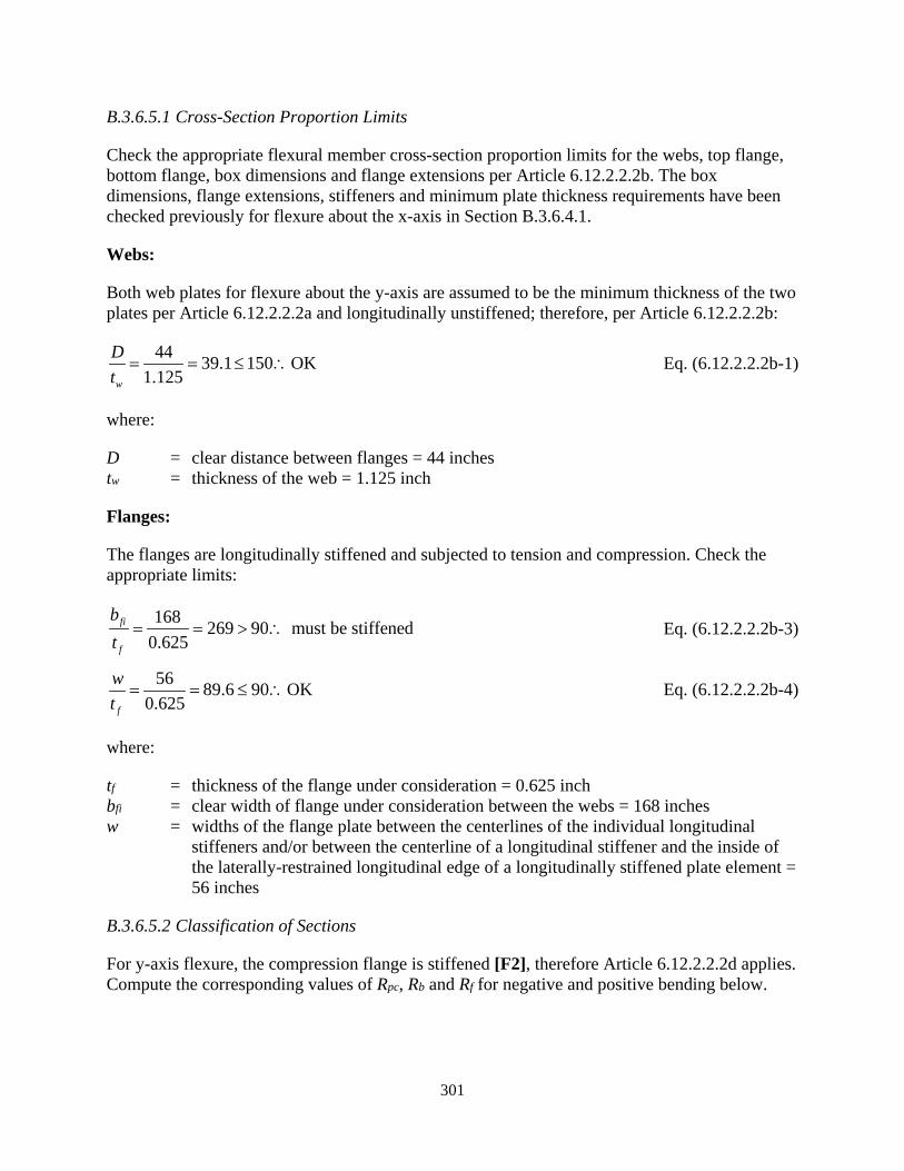
301
B.3.6.5.1 Cross-Section Proportion Limits
Check the appropriate flexural member cross-section proportion limits for the webs, top flange, bottom flange, box dimensions and flange extensions per Article 6.12.2.2.2b. The box dimensions, flange extensions, stiffeners and minimum plate thickness requirements have been checked previously for flexure about the x-axis in Section B.3.6.4.1.
Webs:
Both web plates for flexure about the y-axis are assumed to be the minimum thickness of the two plates per Article 6.12.2.2.2a and longitudinally unstiffened; therefore, per Article 6.12.2.2.2b:
44 39.1 150 OK1.125w
Dt
= = ≤ ∴ Eq. (6.12.2.2.2b-1)
where:
D = clear distance between flanges = 44 inches tw = thickness of the web = 1.125 inch
Flanges:
The flanges are longitudinally stiffened and subjected to tension and compression. Check the appropriate limits:
168 269 90 must be stiffened0.625
fi
f
bt
= = > ∴ Eq. (6.12.2.2.2b-3)
56 89.6 90 OK0.625f
wt
= = ≤ ∴ Eq. (6.12.2.2.2b-4)
where:
tf = thickness of the flange under consideration = 0.625 inch bfi = clear width of flange under consideration between the webs = 168 inches w = widths of the flange plate between the centerlines of the individual longitudinal
stiffeners and/or between the centerline of a longitudinal stiffener and the inside of the laterally-restrained longitudinal edge of a longitudinally stiffened plate element = 56 inches
B.3.6.5.2 Classification of Sections
For y-axis flexure, the compression flange is stiffened [F2], therefore Article 6.12.2.2.2d applies. Compute the corresponding values of Rpc, Rb and Rf for negative and positive bending below.
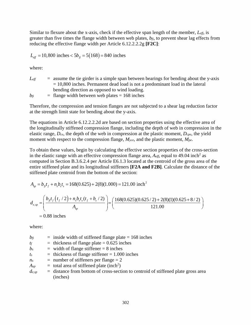
302
Similar to flexure about the x-axis, check if the effective span length of the member, Leff, is greater than five times the flange width between web plates, bfi, to prevent shear lag effects from reducing the effective flange width per Article 6.12.2.2.2g [F2C]:
( )10,800 inches 5 5 168 840 incheseff fiL b= < = =
where:
Leff = assume the tie girder is a simple span between bearings for bending about the y-axis = 10,800 inches. Permanent dead load is not a predominant load in the lateral bending direction as opposed to wind loading.
bfi = flange width between web plates = 168 inches
Therefore, the compression and tension flanges are not subjected to a shear lag reduction factor at the strength limit state for bending about the y-axis.
The equations in Article 6.12.2.2.2d are based on section properties using the effective area of the longitudinally stiffened compression flange, including the depth of web in compression in the elastic range, Dce, the depth of the web in compression at the plastic moment, Dcpe, the yield moment with respect to the compression flange, Myce, and the plastic moment, Mpe.
To obtain these values, begin by calculating the effective section properties of the cross-section in the elastic range with an effective compression flange area, Aeff, equal to 49.04 inch2 as computed in Section B.3.6.2.4 per Article E6.1.3 located at the centroid of the gross area of the entire stiffened plate and its longitudinal stiffeners [F2A and F2B]. Calculate the distance of the stiffened plate centroid from the bottom of the section:
2168(0.625) 2(8)(1.000) 121.00 inchsp fi f s s sA b t n b t= + = + =
( ),
/ 2 ( / 2) 168(0.625)(0.625 / 2) 2(8)(1)(0.625 8 / 2)121.00
0.88 inches
fi f f s s s f se sp
sp
b t t n b t t bd
A
+ + + + = = =
where:
bfi = inside width of stiffened flange plate = 168 inches tf = thickness of flange plate = 0.625 inches bs = width of flange stiffener = 8 inches ts = thickness of flange stiffener = 1.000 inches ns = number of stiffeners per flange = 2 Asp = total area of stiffened plate (inch2) de,sp = distance from bottom of cross-section to centroid of stiffened plate gross area
(inches)
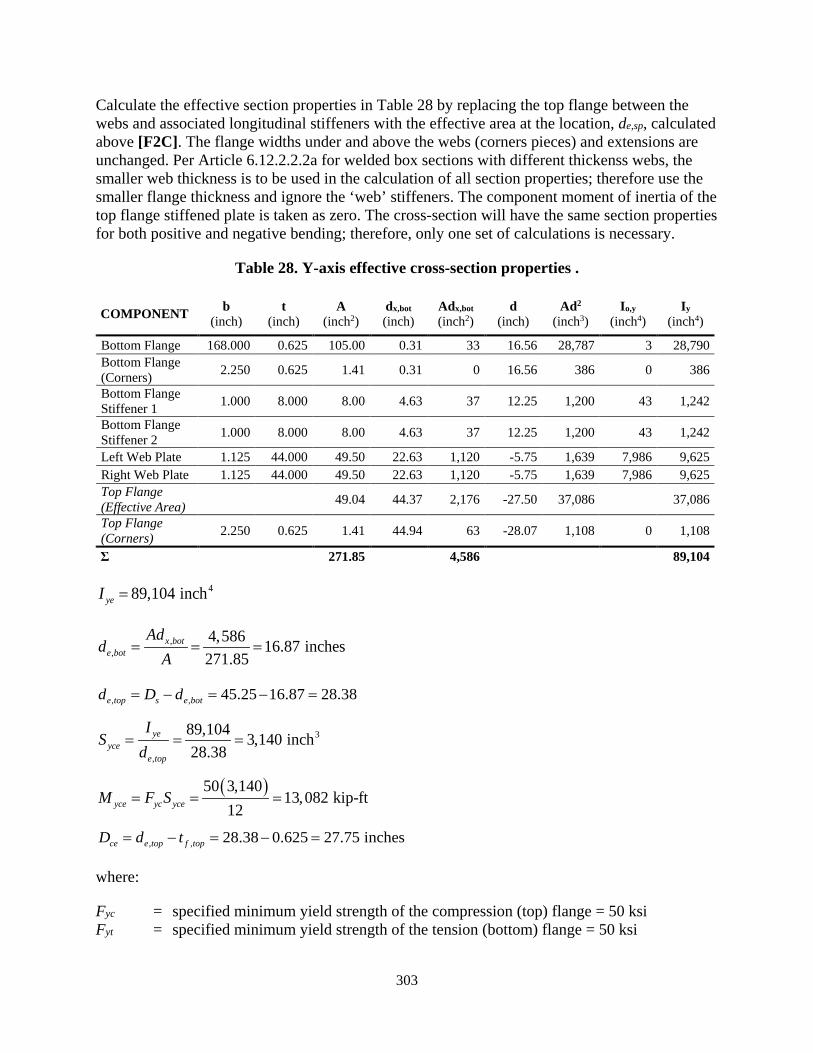
303
Calculate the effective section properties in Table 28 by replacing the top flange between the webs and associated longitudinal stiffeners with the effective area at the location, de,sp, calculated above [F2C]. The flange widths under and above the webs (corners pieces) and extensions are unchanged. Per Article 6.12.2.2.2a for welded box sections with different thickenss webs, the smaller web thickness is to be used in the calculation of all section properties; therefore use the smaller flange thickness and ignore the ‘web’ stiffeners. The component moment of inertia of the top flange stiffened plate is taken as zero. The cross-section will have the same section properties for both positive and negative bending; therefore, only one set of calculations is necessary.
Table 28. Y-axis effective cross-section properties .
COMPONENT b (inch)
t (inch)
A (inch2)
dx,bot (inch)
Adx,bot (inch2)
d (inch)
Ad2 (inch3)
Io,y (inch4)
Iy (inch4)
Bottom Flange 168.000 0.625 105.00 0.31 33 16.56 28,787 3 28,790 Bottom Flange (Corners) 2.250 0.625 1.41 0.31 0 16.56 386 0 386
Bottom Flange Stiffener 1 1.000 8.000 8.00 4.63 37 12.25 1,200 43 1,242
Bottom Flange Stiffener 2 1.000 8.000 8.00 4.63 37 12.25 1,200 43 1,242
Left Web Plate 1.125 44.000 49.50 22.63 1,120 -5.75 1,639 7,986 9,625 Right Web Plate 1.125 44.000 49.50 22.63 1,120 -5.75 1,639 7,986 9,625 Top Flange (Effective Area)
49.04 44.37 2,176 -27.50 37,086 37,086
Top Flange (Corners) 2.250 0.625 1.41 44.94 63 -28.07 1,108 0 1,108
Σ 271.85 4,586 89,104
489,104 inchyeI =
,,
4,586 16.87 inches271.85
x bote bot
Add
A= = =
, , 45.25 16.87 28.38e top s e botd D d= − = − =
3
,
89,104 3,140 inch28.38
yeyce
e top
IS
d= = =
( )50 3,14013,082 kip-ft
12yce yc yceM F S= = =
, , 28.38 0.625 27.75 inchesce e top f topD d t= − = − =
where:
Fyc = specified minimum yield strength of the compression (top) flange = 50 ksi Fyt = specified minimum yield strength of the tension (bottom) flange = 50 ksi
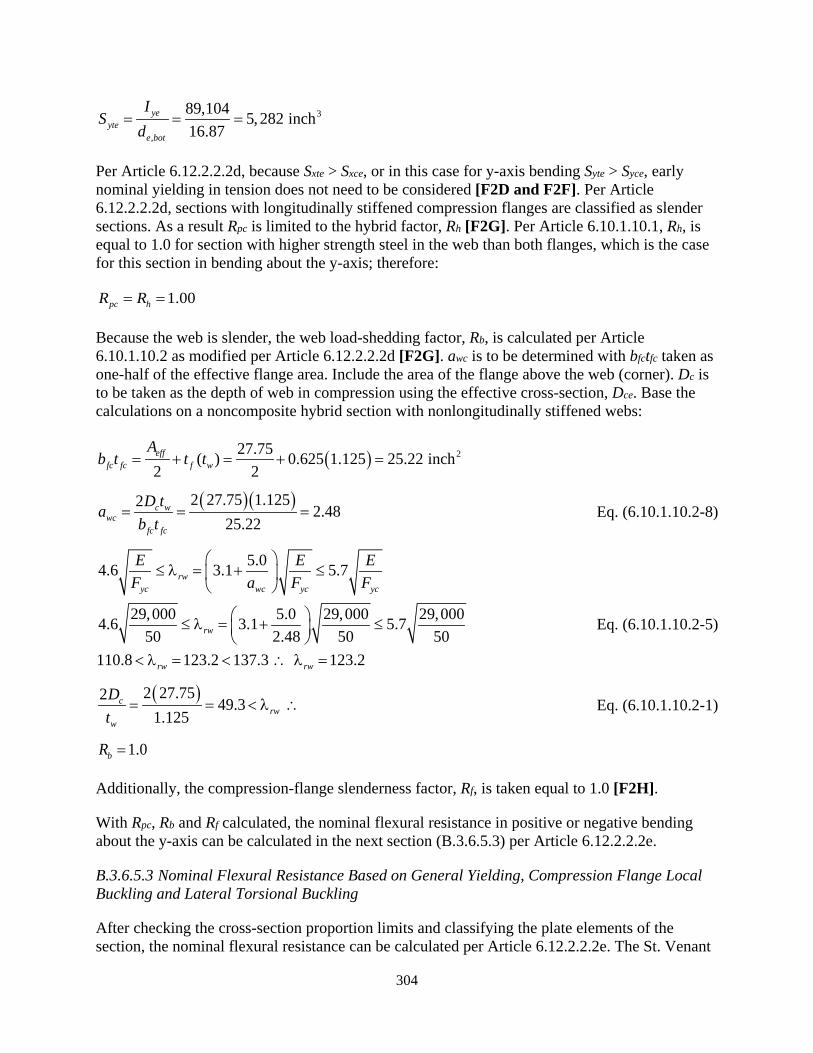
304
3
,
89,104 5,282 inch16.87
yeyte
e bot
IS
d= = =
Per Article 6.12.2.2.2d, because Sxte > Sxce, or in this case for y-axis bending Syte > Syce, early nominal yielding in tension does not need to be considered [F2D and F2F]. Per Article 6.12.2.2.2d, sections with longitudinally stiffened compression flanges are classified as slender sections. As a result Rpc is limited to the hybrid factor, Rh [F2G]. Per Article 6.10.1.10.1, Rh, is equal to 1.0 for section with higher strength steel in the web than both flanges, which is the case for this section in bending about the y-axis; therefore:
1.00pc hR R= =
Because the web is slender, the web load-shedding factor, Rb, is calculated per Article 6.10.1.10.2 as modified per Article 6.12.2.2.2d [F2G]. awc is to be determined with bfctfc taken as one-half of the effective flange area. Include the area of the flange above the web (corner). Dc is to be taken as the depth of web in compression using the effective cross-section, Dce. Base the calculations on a noncomposite hybrid section with nonlongitudinally stiffened webs:
( ) 227.75( ) 0.625 1.125 25.22 inch2 2eff
fc fc f w
Ab t t t= + = + =
( )( )2 27.75 1.1252 2.4825.22
c wwc
fc fc
D tab t
= = = Eq. (6.10.1.10.2-8)
5.04.6 3.1 5.7
29,000 5.0 29,000 29,0004.6 3.1 5.750 2.48 50 50
110.8 123.2 137.3 123.2
rwyc wc yc yc
rw
rw rw
E E EF a F F
≤ λ = + ≤
≤ λ = + ≤
< λ = < ∴ λ =
Eq. (6.10.1.10.2-5)
( )2 27.752 49.3 1.125
crw
w
Dt
= = < λ ∴ Eq. (6.10.1.10.2-1)
1.0bR =
Additionally, the compression-flange slenderness factor, Rf, is taken equal to 1.0 [F2H].
With Rpc, Rb and Rf calculated, the nominal flexural resistance in positive or negative bending about the y-axis can be calculated in the next section (B.3.6.5.3) per Article 6.12.2.2.2e.
B.3.6.5.3 Nominal Flexural Resistance Based on General Yielding, Compression Flange Local Buckling and Lateral Torsional Buckling
After checking the cross-section proportion limits and classifying the plate elements of the section, the nominal flexural resistance can be calculated per Article 6.12.2.2.2e. The St. Venant

305
torsional constant, J, and the cross-sectional area of the box-section member, A, based on gross cross-section properties have been calculated previously for negative bending about the x-axis:
4373,646 inchJ = 2374.13 inchA =
62.5 inchesyr =
( )373,646 374.130.60 0.60(29,000)(62.5)
25(3,140)163,809 inches
r yyr yce
JAL ErF S
= =
=
Compute Lp and Lr [F13]:
600 inchesbL =
( )373,646 374.130.10 0.10(29,000)(62.5)
13,082(12)13,651 inches
p yyce
JAL ErM
= =
=
Eq. (6.12.2.2.2e-4)
( )0.5 0.5 50.0 25.0 ksiyr ycF F= = = Eq. (6.12.2.2.2e-5)
b pL L< [F14]
The unbraced length, Lb, is less than Lp so the flexural resistance is controlled by Eq. 6.12.2.2.2e-1 [F15]:
1.00(1.00)(1.00)(13,082) 13,082 k-ftn b pc f yceM R R R M= = = Eq. (6.12.2.2.2e-1)
B.3.6.5.4 Nominal Plastic Moment Flexural Resistance
For reasons discussed in Section B.3.6.4.4 for flexure about the x-axis, compute the plastic moment flexural resistance, Mype, about the y-axis neglecting any web (flange) longitudinal stiffeners per Article 6.8.2.3.1 while using the effective compression flange area per 6.12.2.2.2d and the minimum web thickness. The flexural resistance is the same for both positive and negative bending.
Calculate the plastic moment flexural resistance, Mype, using Case I in Table D6.1-1 for positive moment with deck reinforcement parameters set to zero. The nomenclature assumes the top flange and upper portion of the web are in compression. The compression flange is longitudinally stiffened. The effective area of the compression flange between webs, Aeff, and its distance from the outside face of the bottom flange, dy,bot, can be found in Table 28. For the tension flange, use the total area of the stiffened plate, Asp, and de,sp from Section B.3.6.5.2. The webs (flanges of the section) are different thicknesses; therefore, use the minimum flange thickness of 1.125 inches for both webs per Article 6.12.2.2.2a. Additionally, the webs extend
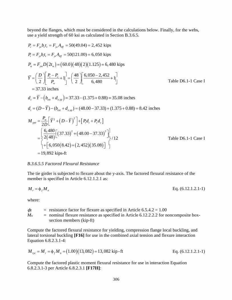
306
beyond the flanges, which must be considered in the calculations below. Finally, for the webs, use a yield strength of 60 ksi as calculated in Section B.3.6.5.
50(49.04) 2,452 kipsc yc c c yc effP F b t F A= = = =
50(121.00) 6,050 kipst yt t t yt effP F b t F A= = = =
( ) ( )( )( )( )2 60.0 48 2 1.125 6,480 kipsw yw wP F D t= = =
48 6,050 2,4521 12 2 6,480
37.33 inchesw
ctP PDYP
− − = + = + =
Table D6.1-1 Case I
( ), 37.33 (1.375 0.88) 35.08 inchesc ext e spd Y b d= − + = − + =
,( ) ( ) (48.00 37.33) (1.375 0.88) 8.42 inchest ext e spd D Y b d= − − + = − + + =
( ) [ ]
( ) ( ) ( )
( ) ( )( )
22
2 2
26,480 37.33 37.332 48 /12
6,050 8.42 2,452 35.08
19,892 kips-ft
48.00
wype t t c c
PM Y D Y Pd P dD = + − + +
+ = + +
−
=
Table D6.1-1 Case I
B.3.6.5.5 Factored Flexural Resistance
The tie girder is subjected to flexure about the y-axis. The factored flexural resistance of the member is specified in Article 6.12.1.2.1 as:
r f nM M= φ Eq. (6.12.1.2.1-1)
where:
ϕf = resistance factor for flexure as specified in Article 6.5.4.2 = 1.00 Mn = nominal flexure resistance as specified in Article 6.12.2.2.2 for noncomposite box-
section members (kip-ft)
Compute the factored flexural resistance for yielding, compression flange local buckling, and lateral torsional buckling [F16] for use in the combined axial tension and flexure interaction Equation 6.8.2.3.1-4:
( )( )1.00 13,082 13,082 kip - ftryc r f nM M M= = φ = = Eq. (6.12.1.2.1-1)
Compute the factored plastic moment flexural resistance for use in interaction Equation 6.8.2.3.1-3 per Article 6.8.2.3.1 [F17H]:

307
( )( )1.00 18,413 18,413 kip - ftrype f ypeM M= φ = =
B.3.6.5.6 Longitudinal Stiffener Design
The longitudinal stiffeners have been previously designed for stiffened plates in compression per Article 6.9.4.2.2e [F2I]. However, the web slenderness (D/tw) is less than 150, the stiffeners are not used for shear capacity; and they are not used to calculate the web load-shedding factor, Rb. Therefore, per Section 3.2.2.2, the stiffeners do not need to be designed to satisfy the provisions of Article 6.10.11.3.
B.3.6.5.7 Transverse Stiffener Design
The web plates (flanges for y-axis bending) are not transversely stiffened [F2J].
B.3.6.6 Y-axis Shear
The tie girder is subjected to shear in the direction of the y-axis. Determine the factored shear resistance per Article 6.12.1.2.3. For shear along the y-axis, the web plates act as the web elements. Article 6.12.1.2.3a defines the factored shear resistance as:
r v nV V= φ Eq. (6.12.1.2.3a-2)
where:
ϕv = resistance factor for shear as specified in Article 6.5.4.2 = 1.00 Vn = for noncomposite rectangular box-section members, nominal shear resistance for
each web calculated as specified in Article 6.10.9 (kips)
Article 6.12.1.2.3a specifies that for box-section members subject to torsion, the factored shear in the web element is to be taken as the sum of the flexural and St. Venant torsional shears. The St. Venant torsional shear in the plate elements will be calculated later for inclusion in the factored shear forces.
Article 6.10.9.1 repeats the factored shear resistance equation from Equation 6.12.1.2.3a-2; defines unstiffened, transversely stiffened, and longitudinally stiffened webs; and specifies the articles concerning the design of transverse and longitudinal stiffeners. The tie girder webs are longitudinally stiffened with a transverse stiffener spacing not exceeding 2D. Therefore, the shear resistance is specified in Article 6.10.9.3.2 for interior panels. Calculate the nominal shear resistance, Vn, per Article 6.10.9.3.2 using the following variables:
D = depth of the web plate measured between the flanges = 168 inches tw = web thickness = 0.625 inches Fyw = specified minimum yield strength of the web = 50 ksi C = ratio of the shear-buckling resistance to the shear yield strength do = transverse stiffener spacing = 150 inches Vp = plastic shear force (kips) Vcr = shear-yielding or shear-buckling resistance (kips)

308
Check the section proportions along the web panel per Equation 6.10.9.3.2-1, replacing bfc and bft as specified for longitudinally stiffened flanges in Article 6.12.1.2.3a. Article 6.12.1.2.3a further requires the shear lag effects of Article 6.12.2.2.2a to be accounted for in their determination, as applicable. However, as determined previously, shear lag effects are not applicable at the strength limit state. Check Equation 6.10.9.3.2-1 for negative and positive bending using the effective flange areas calculated for flexural resistance:
Negative Bending:
, 63.72 21.24 inches1.500
eff cfc
fc
Ab
t= = =
, 7(0.875) 44(1.125) 24.72 inches1.125
eff tft
ft
Ab
t+
= = =
( )2 2(168)(0.625) 3.52 2.5
( ) 21.24(1.500) 24.72(1.125)tw
fc fc ft ft
Dtb t b t
= = >+ +
Positive Bending:
, 52.26 23.23 inches1.125
eff cfc
fc
Ab
t= = =
44 24.00 inches2 2fi
ft
bb = = =
( )2 2(168)(0.625) 3.38 2.5
( ) 23.23(1.125) 24.00(1.500)tw
fc fc ft ft
Dtb t b t
= = >+ +
Therefore, for both negative and positive bending, the nominal shear resistance is based on Equation 6.10.9.3.2-8. Compute the variable, C, per Article 6.10.9.3.2:
2 25 55 5 11.27
150168
o
kdD
= + = + =
Eq. (6.10.9.3.2-7)
( )( )29,000 11.271.12 1.1 6
50.2 90.
0yw
EkF
= =
( )( )29,000 11.271.40 1.4 3
50 00 113.
.yw
EkF
= =
.0.625168 268.8 113 3
w
Dt
= = > ∴
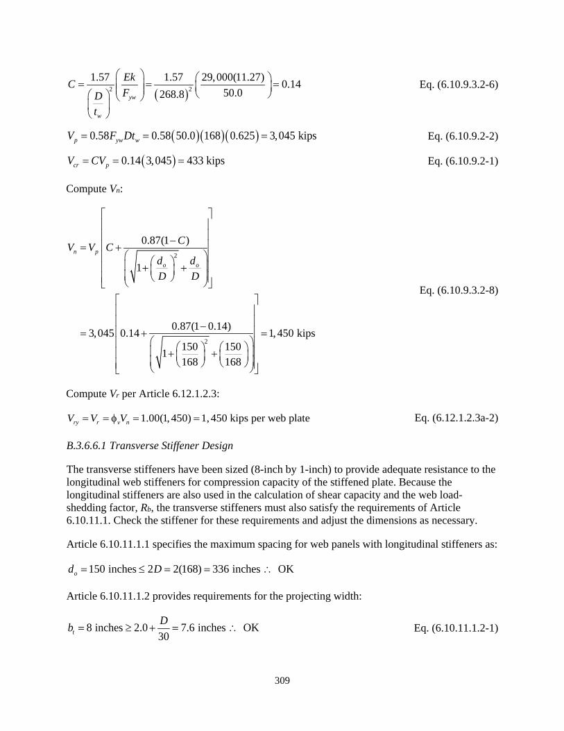
309
( )2 21.57 1.57 29,000(11.27) 0.14
50.0268.8yw
w
EkCFD
t
= = =
Eq. (6.10.9.3.2-6)
( )( )( )0.58 0.58 50.0 3,045 kips168 0.625p yw wV F Dt= = = Eq. (6.10.9.2-2)
( )0.14 3,045 433 kipscr pV CV= = = Eq. (6.10.9.2-1)
Compute Vn:
2
2
0.87(1 )
1
0.87(1 0.14)3,045 0.14 1,450 kips150 1501168 168
n p
o o
CV V Cd dD D
− = +
+ + − = + =
+ +
Eq. (6.10.9.3.2-8)
Compute Vr per Article 6.12.1.2.3:
1.00(1,450) 1,450 kips per web platery r v nV V V= = φ = = Eq. (6.12.1.2.3a-2)
B.3.6.6.1 Transverse Stiffener Design
The transverse stiffeners have been sized (8-inch by 1-inch) to provide adequate resistance to the longitudinal web stiffeners for compression capacity of the stiffened plate. Because the longitudinal stiffeners are also used in the calculation of shear capacity and the web load-shedding factor, Rb, the transverse stiffeners must also satisfy the requirements of Article 6.10.11.1. Check the stiffener for these requirements and adjust the dimensions as necessary.
Article 6.10.11.1.1 specifies the maximum spacing for web panels with longitudinal stiffeners as:
150 inches 2 2(168) 336 inches OKod D= ≤ = = ∴
Article 6.10.11.1.2 provides requirements for the projecting width:
8 inches 2.0 7.6 inches OK30tDb = ≥ + = ∴ Eq. (6.10.11.1.2-1)
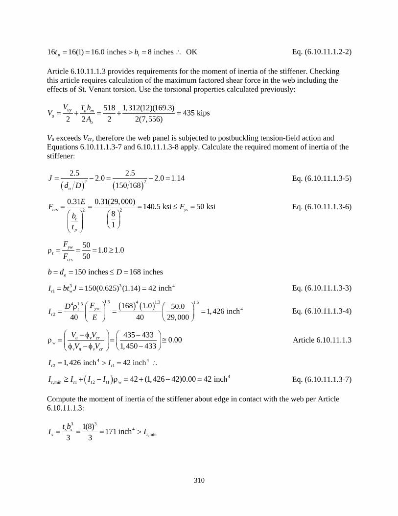
310
16 16(1) 16.0 inches 8 inches OKp tt b= = > = ∴ Eq. (6.10.11.1.2-2)
Article 6.10.11.1.3 provides requirements for the moment of inertia of the stiffener. Checking this article requires calculation of the maximum factored shear force in the web including the effects of St. Venant torsion. Use the torsional properties calculated previously:
518 1,312(12)(169.3) 435 kips2 2 2 2(7,556)uy u m
uo
V T hVA
= + = + =
Vu exceeds Vcr, therefore the web panel is subjected to postbuckling tension-field action and Equations 6.10.11.1.3-7 and 6.10.11.1.3-8 apply. Calculate the required moment of inertia of the stiffener:
( ) ( )2 22.5 2.52.0 2.0 1.14
150 168o
Jd D
= − = − = Eq. (6.10.11.1.3-5)
2 20.31 0.31(29,000) 140.5 ksi 50 ksi
81
crs ys
t
p
EF Fbt
= = = ≤ =
Eq. (6.10.11.1.3-6)
50 1.0 1.050
ywt
crs
FF
ρ = = = ≥
150 inches 168 inchesob d D= = ≤ = 3 3 4
1 150(0.625) (1.14) 42 incht wI bt J= = = Eq. (6.10.11.1.3-3)
( ) ( )1.5 4 1.3 1.54 1.34
2
168 1.0 50.0 1,426 inch40 40 29,000
ywtt
FDIE
ρ = = =
Eq. (6.10.11.1.3-4)
435 433 0.001,450 433
u v crw
v n v cr
V VV V
− φ − ρ = = ≅ φ − φ − Article 6.10.11.1.3
4 42 11, 426 inch 42 inch t tI I= > = ∴
( ) 4,min 1 2 1 42 (1,426 42)0.00 42 incht t t t wI I I I≥ + − ρ = + − = Eq. (6.10.11.1.3-7)
Compute the moment of inertia of the stiffener about edge in contact with the web per Article 6.10.11.1.3:
3 34
,min 1(8) 171 inch
3 3s s
s tt bI I= = = >

311
The moment of inertia of an 8-inch by 1-inch stiffener is adequate. At the diaphragm locations, a minimum 1-inch thickness would be prudent along with a minimum clear distance from the face of the web to the edge of the access hole of 8 inches, with a larger distance being preferred.
B.3.6.7 X-axis Shear
The tie girder is subjected to shear in the direction of the x-axis. Determine the factored shear resistance per Article 6.12.1.2.3. The tie girder flanges are longitudinally unstiffened for shear capacity and Rb, therefore, compute the shear resistance for unstiffened webs per Article 6.10.9.2. The flanges are different thickness, therefore base the shear resistance on the minimum flange thickness using these variables:
D = depth of the web plate measured between the flanges = 44 inches tw = web thickness = 1.125 inches Fyw = specified minimum yield strength of the web = 60 ksi per Article 6.10.1.3
Compute the variable, C, per Article 6.10.9.3.2:
5k =
( )( )29,000 51.12 1.12 55.1
60.0yw
EkF
= =
( )( )29,000 51.40 1.40 68.8
60.0yw
EkF
= =
.1.125
44 39.1 55 1w
Dt
= = < ∴
1.0C = Eq. (6.10.9.3.2-4)
Compute Vn per Article 6.10.9.2:
( )( )( )0.58 0.58 60.0 1,723 kips44 1.125p yw wV F Dt= = = Eq. (6.10.9.2-2)
( ) s1, 71.0 7 ki2 p3 1, 23n cr pV V CV= = = = Eq. (6.10.9.2-1)
Compute Vr per Article 6.12.1.2.3:
( )( )1.00 1,723 kips per cover plate1,723rx r v nV V V= = φ = = Eq. (6.12.1.2.3a-2)
Even though no transverse stiffener design is required, calculate the maximum factored shear force in the web including the effects of St. Venant torsion similar to y-axis shear for checking demand versus capacity in Section B.3.7.1:

312
67 1,312(12)(44.625) 80 kips2 2 2 2(7,556)uy u m
uo
V T bVA
= + = + =
B.3.7 Demand to Capacity and Interaction Checks
The factored force effects and individual resistances have been calculated for the cross-section. In this section, compare the shear force effects, or demand, D, to the factored resistances, or capacity, C, and calculate a D/C ratio, which should be less than or equal to 1.00 for design. In addition to individual component shear checks, investigate axial and flexure interaction for tension with reductions for torsional and flexural shear stresses as applicable.
The following checks are based on force effects from the strength limit state. While unlikely, the engineer should ensure that no service or constructibility load combinations result in higher forces on the cross-section. Service, fatigue and constructibility are investigated later to prevent buckling of slender plate elements and permanent deformations.
B.3.7.1 Shear
Compare the factored shear resistance of a component web plate in the direction of each principal axis to the corresponding maximum strength limit state factored shear from Table 23. Similar to Article 6.11.9 for the shear resistance of a composite box, or tub girder, the total shear in a web should be the sum of the flexural and St. Venant torsional shears when the section is subjected to torsion. The factored y- and x-axis web shear forces were computed in Sections B.3.6.6 and B.3.6.7, respectively.
Check web plates for shear acting parallel to the y-axis:
435 kipsuyV =
1, 450 kipsryV =
( ) 01, 45435 0.30
01.0
vyD
C = = <
Check flange plates for shear acting parallel to the x-axis:
80 kipsuxV =
1,723 kipsrxV =
( ) 01,723
80 0.05 1.0vx
DC = = <
B.3.7.2 Combined Axial Compression and Flexure
The cross-section does not resist axial compression, therefore the interaction equations of Article 6.9.2.2 do not apply.
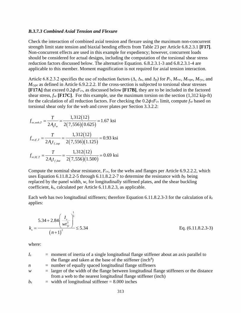
313
B.3.7.3 Combined Axial Tension and Flexure
Check the interaction of combined axial tension and flexure using the maximum non-concurrent strength limit state tension and biaxial bending effects from Table 23 per Article 6.8.2.3.1 [F17]. Non-concurrent effects are used in this example for expediency; however, concurrent loads should be considered for actual designs, including the computation of the torsional shear stress reduction factors discussed below. The alternative Equation. 6.8.2.3.1-3 and 6.8.2.3.1-4 are applicable to this member. Moment magnification is not required for axial tension interaction.
Article 6.8.2.3.2 specifies the use of reduction factors (Δ, Δx, and Δy) for Pr, Mrxc, Mrxpe, Mryc, and Mrype as defined in Article 6.9.2.2.2. If the cross-section is subjected to torsional shear stresses [F17A] that exceed 0.2𝜙𝜙TFcv, as discussed below [F17B], they are to be included in the factored shear stress, fve [F17C]. For this example, use the maximum torsion on the section (1,312 kip-ft) for the calculation of all reduction factors. For checking the 0.2𝜙𝜙TFcv limit, compute fve based on torsional shear only for the web and cover plates per Section 3.3.2.2:
( )( )( ), ,
1,312 121.67 ksi
2 2 7,556 0.625ve web To w
TfA t
= = =
( )( )( ), ,
,
1,312 120.93 ksi
2 2 7,556 1.125ve tf To f top
TfA t
= = =
( )( )( ), ,
,
1,312 120.69 ksi
2 2 7,556 1.500ve bf To f bot
TfA t
= = =
Compute the nominal shear resistance, Fcv, for the webs and flanges per Article 6.9.2.2.2, which uses Equation 6.11.8.2.2-5 through 6.11.8.2.2-7 to determine the resistance with bfc being replaced by the panel width, w, for longitudinally stiffened plates, and the shear buckling coefficient, ks, calculated per Article 6.11.8.2.3, as applicable.
Each web has two longitudinal stiffeners; therefore Equation 6.11.8.2.3-3 for the calculation of ks applies:
( )
13
3
2
5.34 2.845.34
1
s
fcs
Iwt
kn
+
= ≤+
Eq. (6.11.8.2.3-3)
where:
Is = moment of inertia of a single longitudinal flange stiffener about an axis parallel to the flange and taken at the base of the stiffener (inch4)
n = number of equally spaced longitudinal flange stiffeners w = larger of the width of the flange between longitudinal flange stiffeners or the distance
from a web to the nearest longitudinal flange stiffener (inch) bs = width of longitudinal stiffener = 8.000 inches
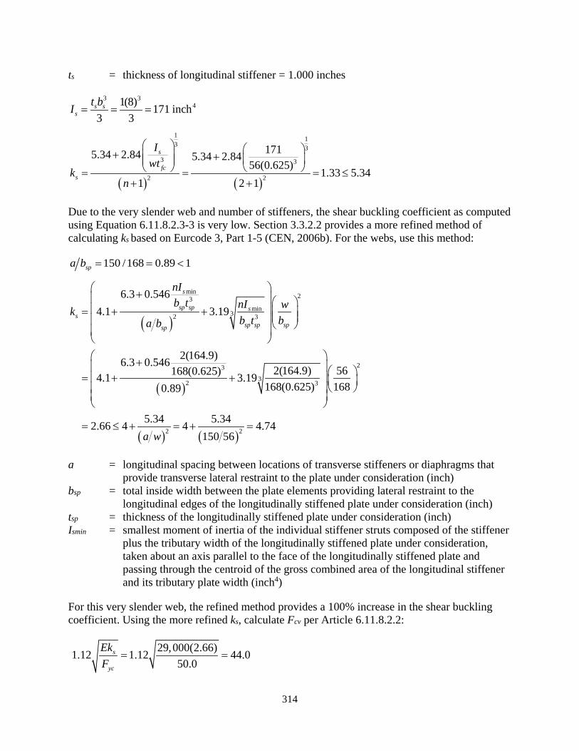
314
ts = thickness of longitudinal stiffener = 1.000 inches
3 341(8) 171 inch
3 3s s
st bI = = =
( ) ( )
1 13 3
3 3
2 2
1715.34 2.84 5.34 2.8456(0.625)
1.33 5.341 2 1
s
fcs
Iwt
kn
+ + = = = ≤
+ +
Due to the very slender web and number of stiffeners, the shear buckling coefficient as computed using Equation 6.11.8.2.3-3 is very low. Section 3.3.2.2 provides a more refined method of calculating ks based on Eurcode 3, Part 1-5 (CEN, 2006b). For the webs, use this method:
150 /168 0.89 1spa b = = <
( )
( )
( ) ( )
min23
min32 3
23
32 3
2 2
6.3 0.5464.1 3.19
2(164.9)6.3 0.5462(164.9) 56168(0.625)4.1 3.19
168(0.625) 1680.89
5.34 5.342.66 4 4 4.74150 56
s
sp sp ss
sp sp spsp
nIb t nI wk
b t ba b
a w
+ = + + + = + +
= ≤ + = + =
a = longitudinal spacing between locations of transverse stiffeners or diaphragms that provide transverse lateral restraint to the plate under consideration (inch)
bsp = total inside width between the plate elements providing lateral restraint to the longitudinal edges of the longitudinally stiffened plate under consideration (inch)
tsp = thickness of the longitudinally stiffened plate under consideration (inch) Ismin = smallest moment of inertia of the individual stiffener struts composed of the stiffener
plus the tributary width of the longitudinally stiffened plate under consideration, taken about an axis parallel to the face of the longitudinally stiffened plate and passing through the centroid of the gross combined area of the longitudinal stiffener and its tributary plate width (inch4)
For this very slender web, the refined method provides a 100% increase in the shear buckling coefficient. Using the more refined ks, calculate Fcv per Article 6.11.8.2.2:
29,000(2.66)1.12 1.12 44.050.0
s
yc
EkF
= =
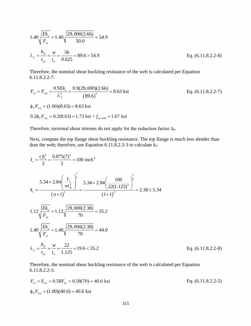
315
29,000(2.66)1.40 1.40 54.950.0
s
yc
EkF
= =
56 89.6 54.90.625
fcf
fc w
b wt t
λ = = = = > Eq. (6.11.8.2.2-8)
Therefore, the nominal shear buckling resistance of the web is calculated per Equation 6.11.8.2.2-7:
( )22
0.9 0.9(29,000)(2.66) 8.63 ksi89.6
scv cvy
f
EkF F= = = =λ
Eq. (6.11.8.2.2-7)
(1.00)(8.63) 8.63 ksiT cvyFφ = =
,0.2 0.2(8.63) 1.73 ksi > 1.67 ksiT cvy ve webF fφ = = =
Therefore, torsional shear stresses do not apply for the reduction factor ∆y.
Next, compute the top flange shear buckling resistance. The top flange is much less slender than than the web; therefore, use Equation 6.11.8.2.3-3 to calculate ks:
3 340.875(7) 100 inch
3 3s s
st bI = = =
( ) ( )
1 13 3
3 3
2 2
1005.34 2.84 5.34 2.8422(1.125)
2.38 5.341 1 1
s
fcs
Iwt
kn
+ + = = = ≤
+ +
29,000(2.38)1.12 1.12 35.270
s
yc
EkF
= =
29,000(2.38)1.40 1.40 44.070
s
yc
EkF
= =
22 19.6 35.21.125
fcf
fc w
b wt t
λ = = = = < Eq. (6.11.8.2.2-8)
Therefore, the nominal shear buckling resistance of the web is calculated per Equation 6.11.8.2.2-5:
F 0.58 0.58(70) 40.6 ksicv cvx ycF F= = = = Eq. (6.11.8.2.2-5)
(1.00)(40.6) 40.6 ksiT cvxFφ = =

316
, ,0.2 0.2(40.6) 8.12 ksi 0.93 ksiT cvx ve tf TF fφ = = > =
Therefore, torsional shear stresses do not apply for the reduction factor ∆x based on the top flange [F17B].
Compute the bottom flange shear buckling resistance. The bottom flange is unstiffened, therefore ks is equal to 5.34 per Article 6.11.8.2.2.
29,000(5.34)1.12 1.12 52.770.0
s
yc
EkF
= =
29,000(5.34)1.40 1.40 65.870
s
yc
EkF
= =
44 29.3 52.71.500
fcf
fc
bt
λ = = = < Eq. (6.11.8.2.2-8)
Therefore, the nominal shear buckling resistance of the bottom flange is calculated per Eq. 6.11.8.2.2-5:
0.58 0.58(70.0) 40.6 ksicv cvx ycF F F= = = = Eq. (6.11.8.2.2-5)
(1.00)(40.6) 40.6 ksiT cvxFφ = =
, ,0.2 0.2(40.6) 8.12 ksi 0.69 ksiT cvx ve bf TF fφ = = > =
Therefore, torsional shear stresses do not apply for the reduction factor ∆x based on the bottom flange [F17B].
In addition to torsional shear stresses, if Pu/Pr exceeds 0.05 [F17E], which it does for axial tension as shown later, the flexural shear stresses are to be included in fve for the calculation of the reduction factors ∆, ∆x and ∆y [F17F]. The torsional and flexural shears should be concurrent with the factored force effect (Pu, Mux, and Muy) being considered.
Compute the flexural shear stresses in the web plates for the respective directions of applied shear using the factored shear and inside plate widths for inclusion in the calculation of the reduction factors:
( ) ( ), ,
2 518 22.47 ksi
168(0.625)uy
ve web Vw
Vf
Dt= = =
( ) ( ), ,
,
2 67 20.68 ksi
44(1.125)ux
ve tf Vfi f top
Vf
b t= = =
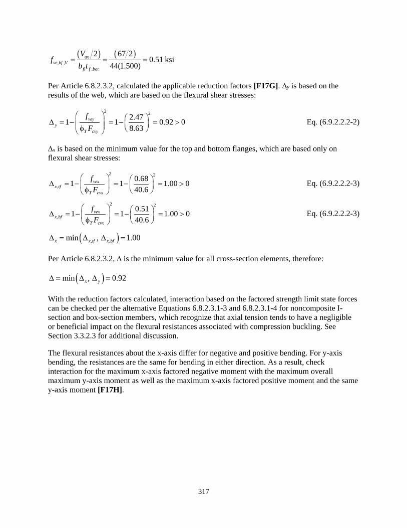
317
( ) ( ), ,
,
2 67 20.51 ksi
44(1.500)ux
ve bf Vfi f bot
Vf
b t= = =
Per Article 6.8.2.3.2, calculated the applicable reduction factors [F17G]. ∆y is based on the results of the web, which are based on the flexural shear stresses:
2 22.471 1 0.92 08.63
veyy
T cvy
fF
∆ = − = − = > φ Eq. (6.9.2.2.2-2)
∆x is based on the minimum value for the top and bottom flanges, which are based only on flexural shear stresses:
2 2
,0.681 1 1.00 040.6
vexx tf
T cvx
fF
∆ = − = − = > φ Eq. (6.9.2.2.2-3)
2 2
,0.511 1 1.00 040.6
vexx bf
T cvx
fF
∆ = − = − = > φ Eq. (6.9.2.2.2-3)
( ), ,min , 1.00x x tf x bf∆ = ∆ ∆ =
Per Article 6.8.2.3.2, ∆ is the minimum value for all cross-section elements, therefore:
( )min , 0.92x y∆ = ∆ ∆ =
With the reduction factors calculated, interaction based on the factored strength limit state forces can be checked per the alternative Equations 6.8.2.3.1-3 and 6.8.2.3.1-4 for noncomposite I-section and box-section members, which recognize that axial tension tends to have a negligible or beneficial impact on the flexural resistances associated with compression buckling. See Section 3.3.2.3 for additional discussion.
The flexural resistances about the x-axis differ for negative and positive bending. For y-axis bending, the resistances are the same for bending in either direction. As a result, check interaction for the maximum x-axis factored negative moment with the maximum overall maximum y-axis moment as well as the maximum x-axis factored positive moment and the same y-axis moment [F17H].

318
Negative X-Axis Bending:
Check interaction Equation 6.8.2.3.1-3 for preventing tensile failure:
,
,
5, 275 29,161 3,010 0.80 1.0 OK0.92(17,771) 1.00(94,293) 0.92(19,892)
ux neg uyu
ry x rxpe neg y rype
M MPP M M
+ + ∆ ∆ ∆
= + + = > ∴
Eq. (6.8.2.3.1-3)
Check interaction Equation 6.8.2.3.1-4 preventing compression failure:
,
,
29,161 3,010 0.70 1.0 OK1.00(64,959) 0.92(13,082)
ux neg uy
x rxc neg y ryc
M MM M
+ ∆ ∆
= + = < ∴
Eq. (6.8.2.3.1-4)
Positive X-Axis Bending:
,
,
5, 275 30,098 3,010 0.79 1.0 OK0.92(17,771) 1.00(99,828) 0.92(19,892)
ux pos uyu
ry x rxpe pos y rype
M MPP M M
+ + ∆ ∆ ∆
= + + = > ∴
Eq. (6.8.2.3.1-3)
,
,
30,098 3,010 0.69 1.0 OK1.00(67,794) 0.92(13,082)
ux pos uy
x rxc pos y ryc
M MM M
+ = + = < ∴ ∆ ∆
Eq. (6.8.2.3.1-4)
Therefore the section is adequate for the fictitious loads of this example.
Tension Flange with Holes:
Per Article 6.12.2.2.2a, because the cross-section is subjected to flexure combined with axial tension, Article 6.8.2.3.3 for tension flanges with holes needs to be investigated [F17I]. At the field splice, the cross-section contains 30 bolts in each web, 13 in each flange and one in each longitudinal stiffener. Therefore, Article 6.8.2.3.3 applies to bending about both principal axes. Use the following variables to check the Article:
Mr = factored tension rupture flexural resistance about the axis of bending under consideration as computed in Equation 6.8.2.3.3-2 (kip-ft)
Pr = factored tensile rupture resistance of the net section at the bolt holes based on Equation 6.8.2.1-2 for members in axial tension (kips)
Anf = net area of the tension flange determined as specified in Article 6.8.3 (inch2) Agf = gross area of the tension flange (inch2) Fu = specified minimum tensile strength of the tension flange (ksi)

319
Fyt = yield strength of the tension flange (ksi) St = elastic section modulus of the gross cross-section about the axis of bending to the
tension flange including shear lag effects, as applicable (inch3)
Because the cross-section is noncomposite, St is equal to the previously computed section moduli used for computing factored flexural resistance, which includes the effects of shear lag, where applicable. The section is asymmetric about the x-axis; therefore, check the section for negative and positive moments. The section is symmetric about the y-axis; therefore, check the section only for the maximum bending moment. Conservatively combine the maximum bending moment about the axis in question with the maximum non-concurrent axial tensile load.
Negative X-Axis Bending:
248(1.125) 7(0.875) 60.13 inchgf ft ft s sA tb bt= = ++ =
( )( ) 260.13 1.125 13(1.125) 1(0.875) 42.69 inch
nf gf h sole f ft snA t tA d n= −
=
+
− + =
( )( )
( )( )
42.690.84 0.84 85.0 16,258 /1260.13
68,678 kip-ft 70.0 16,258 /12 94,836 kip-ft
nfr u t y t
gf
y t
AM F S F S
A
F S
= ≤ = = ≤ = =
Eq. (6.8.2.3.3-2)
, 5, 275 29,161 0.78 1.0 OK14,979 68,678
ux negu
ru r
MPP M
+ = + = ≤ ∴ Eq. (6.8.2.3.3-1)
Positive X-Axis Bending:
248(1.500) 72.00 inchgf ft ftA b t= = =
( ) ( ) 272.00 1.125 13(1.500) 50.06 inchnf gf hole f ftA A d n t= − = − =
( )( )
( )( )
50.060.84 0.84 85.0 17,496 /1272.00
72,383 kip-ft 70.0 17,383 /12 102,061 kip-ft
nfr u t y t
gf
y t
AM F S F S
A
F S
= ≤ = = ≤ = =
Eq. (6.8.2.3.3-2)
, 5, 275 30,098 0.77 1.0 OK14,979 72,383
ux posu
ru r
MPP M
+ = + = ≤ ∴ Eq. (6.8.2.3.3-1)
Y-Axis Bending:
2168(0.625) 2(8)(1) 1212 .00 inchgf ft ft s sA tb bt= = ++ =

320
( )( ) 2121.00 1.125 30(0.625) 2(1)(1.000) 97 i
2
.66 nchnf gf hol se f ft sA t n tA d n= −
= −
+
+ =
( )( )
( )( ) t
5, 2 297.660.84 0.84 65.0 /12121.00
1 9,396 kip-ft 50.0 5,282 /12 22,007 kip-f
8nfr u t y t
gf
y t
AM F S F S
A
F S
= ≤ = = ≤ = =
Eq. (6.8.2.3.3-2)
5, 275 3,010 0.51 1.0 OK, 14 97 ,1 3969 9
uyu
ru r
MPP M
+ = + = ≤ ∴ Eq. (6.8.2.3.3-1)
B.3.7.4 Cross-Section Distortion
Article 6.12.2.2.2a specifies that for noncomposite box-section members subject to torsion, transverse bending stresses due to cross-section distortion should be considered for fatigue and at the strength limit state [F17D]. The factored transverse plate bending stresses should not exceed 20.0 ksi at the strength limit state. Longitudinal warping stresses due to cross-section distortion should be considered for fatigue, but may be ignored at the strength limit state. Transverse bending and longitudinal warping stresses due to cross-section distortion are to be determined by rational structural analysis. Transverse stiffeners attached to the webs or flanges should be considered effective with the web or flange in resisting transverse bending.
The commentary references the beam-on-elastic foundation (BEF) analogy method for determining the cross-sectional distortion stresses as discussed in Article C6.11.1.1. The method was presented by Wright and Abdel-Samad (1968) with sample calculations provided by Heins and Hall (1981). In addition to these references, the Steel Bridge Design Handbook provides excellent examples based on composite tub girders (FHWA, 2015). The calculations for a noncomposite box-section are similar to a tub girder, therefore the steps involved are not provided in this example. See Wright and Abdel-Samad for replacing the stiffness of a crossframe (for tub girders) with the stiffness of a plate diaphragm where applicable. Finally, for diaphragms with access holes, see Ziemian (2010), which presents work by Rockey relating the critical buckling shear stress of a square plate in pure shear with a circular hole to one without.
B.3.8 Service, Fatigue and Constructibility
Article 6.12.2.2.2f specifies requirements for the service and fatigue limit states and constructibility. Check the tie girder for these requirements. The first requirement is that the webs are to satisfy the provisions of Article 6.10.3.3 [F19] for constructibility, which requires that the maximum web shear during construction be less than the factored critical shear resistance, ϕvVcr. Calculate the maximum web shear during construction due to the flexural and St. Venant torsional shear and compare to the critical shear resistance calculated previously:
301 425(12)(169.3) 208 kips2 2 2 2(7,556)uy u m
uo
V T hVA
= + = + =
208 kips 1.00(433) 433 kips OKu v crV V= < φ = = ∴ Eq. (6.10.3.3-1)

321
Similar to the webs, check the thinnest (top) flange plate for shear in the direction of the x-axis:
29 425(12)(44.625) 71 kips2 2 2 2(7,556)ux u m
uo
V T bVA
= + = + =
71 kips 1.00(1,723) 1,723 kips OKu v crV V= < φ = = ∴ Eq. (6.10.3.3-1)
The second requirement of Article 6.12.2.2.2f is that webs satisfy the provisions of Article 6.10.5.3 for fatigue [F19], which requires that the shear in the web due to the unfactored permanent dead load plus the factored Fatigue I load be less than the factored critical shear resistance, ϕvVcr. The dead load plus factored fatigue load flexure and St. Venant torsional shears are lower than the factored constructibility forces above; therefore, say OK by inspection.
The third requirement of Article 6.12.2.2.2f is the satisfaction of Article 6.9.4.5 at the fatigue and service limit states, and for constructibility when the section is a slender web section as defined in Article 6.12.2.2.2c [F21]; the section contains slender longitudinally stiffened plate panels as defined in Article E6.1.2; or the slenderness, λf, of a longitudinally unstiffened compression flange exceeds λrf1 as defined in Article 6.12.2.2.2c. All three conditions apply to the tie girder cross-section when considering both axes of bending. Therefore, check the section per Article 6.9.4.5.
Article 6.9.4.5 requires that the maximum Service II load combination and factored load for constructibility compression stresses in slender unstiffened plate elements or slender longitudinally stiffened plate panels satisfy Equation 6.9.4.5-1. An exception is provided for webs of noncomposite box-section members subject to flexure only containing longitudinally unstiffened webs or webs with only one longitudinal stiffener; such members are to be checked for web bend buckling at these limit states according to the less restrictive web bend-buckling provisions of Article 6.11. This exception does not apply in this case.
To begin checking Equation 6.9.4.5-1, compute the slenderness ratios for all slender unstiffened (bottom flange) and slender longitudinally stiffened (webs) plate panels, where the distance is measured between stiffening elements. The slenderness of the stiffeners and flange extensions are not necessary because they are required to be sized as nonslender and compact.
,,
,
44 29.31.500
f botf bot
f bot
bt
λ = = =
56 89.60.625
webweb
w
wt
λ = = =
Use a conservative plate-buckling coefficient, k, equal to 4.0 to compute the maximum allowable longitudinal compressive stress due to combined flexure and axial loading, fc,max, for the bottom flange and web plates, respectively:
,max, 2 2,
0.9 0.9(29,000)(4.0) 121.3 ksi 70 ksi(29.3)c bot y
f bot
Ekf F= = = > =λ
Eq. (6.9.4.5-1)

322
,max, 2 2
0.9 0.9(29,000)(4.0) 13.0 ksi 50 ksi(89.6)c w y
web
Ekf F= = = < =λ
Eq. (6.9.4.5-1)
By inspection, the maximum compression stress in the flanges will not exceed the maximum allowable stress. The limit of 13.0 ksi for the web, however, may be exceeded. Therefore, compute the peak stress at the centerline of the web, which occurs at the top or bottom of the web under axial load and biaxial bending. To calculate the compressive stresses, compute the section properties about the x and y-axis using the gross cross-section adjusted for negative flexure shear lag effects.
Check the shear lag requirements for the service and fatigue limit states per Article 6.12.2.2.2g. For the service limit state and constructibility, the same strength limit state shear lag requirements apply to simple spans and positive moment regions; therefore, there is no reduction in positive bending in this example (Section B.3.6.4.2).
For negative moment regions, when Leff is less than thirty times bfi, Equation. 6.12.2.2.2g-2 and 6.12.2.2.2g-3 apply to the effective flange areas for the calculation of service limit state and constructibility stresses. For the tie girder, this would be the region at the floor beam connections.
240 30 30(44) 1320 incheseff fiL b= < = =
Therefore, Equation 6.12.2.2.2g-2 or 6.12.2.2.2g-3 must be checked for the negative bending region, depending on the value of Leff/bfi:
240 5.5 1544
eff
fi
Lb
= = ≤ ∴
The shear lag reduction factor is:
( ) ( )
2
2
0.376 0.0542 0.00156
240 2400.376 0.0542 0.0015644 44
5 240 50.625 1.091
44
eff eff
fi fi
eff
fi
L Lb b
Lb
+ − = + −
= ≤ = =
Eq. 6.12.2.2.2g-2
Therefore, apply a 0.625 reduction factor to the effective area of the compression or tension flanges between the inside faces of the web. Conservatively apply this reduction factor for positive and negative moments in this example.
Check the service limit state and constructibility shear lag requirements for the y-axis. Shear lag was shown to not control for strength in Section B.3.6.5.2, which also applies to simple spans
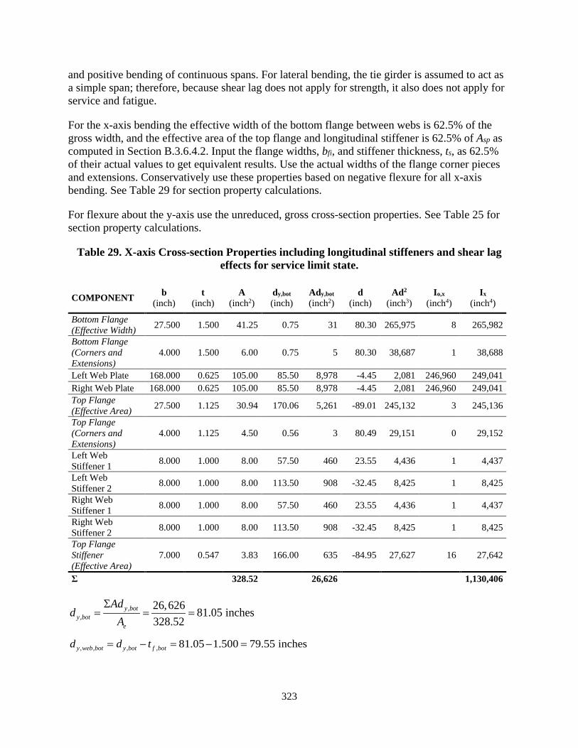
323
and positive bending of continuous spans. For lateral bending, the tie girder is assumed to act as a simple span; therefore, because shear lag does not apply for strength, it also does not apply for service and fatigue.
For the x-axis bending the effective width of the bottom flange between webs is 62.5% of the gross width, and the effective area of the top flange and longitudinal stiffener is 62.5% of Asp as computed in Section B.3.6.4.2. Input the flange widths, bfi, and stiffener thickness, ts, as 62.5% of their actual values to get equivalent results. Use the actual widths of the flange corner pieces and extensions. Conservatively use these properties based on negative flexure for all x-axis bending. See Table 29 for section property calculations.
For flexure about the y-axis use the unreduced, gross cross-section properties. See Table 25 for section property calculations.
Table 29. X-axis Cross-section Properties including longitudinal stiffeners and shear lag effects for service limit state.
COMPONENT b (inch)
t (inch)
A (inch2)
dy,bot (inch)
Ady,bot (inch2)
d (inch)
Ad2 (inch3)
Io,x (inch4)
Ix (inch4)
Bottom Flange (Effective Width) 27.500 1.500 41.25 0.75 31 80.30 265,975 8 265,982
Bottom Flange (Corners and Extensions)
4.000 1.500 6.00 0.75 5 80.30 38,687 1 38,688
Left Web Plate 168.000 0.625 105.00 85.50 8,978 -4.45 2,081 246,960 249,041 Right Web Plate 168.000 0.625 105.00 85.50 8,978 -4.45 2,081 246,960 249,041 Top Flange (Effective Area) 27.500 1.125 30.94 170.06 5,261 -89.01 245,132 3 245,136
Top Flange (Corners and Extensions)
4.000 1.125 4.50 0.56 3 80.49 29,151 0 29,152
Left Web Stiffener 1 8.000 1.000 8.00 57.50 460 23.55 4,436 1 4,437
Left Web Stiffener 2 8.000 1.000 8.00 113.50 908 -32.45 8,425 1 8,425
Right Web Stiffener 1 8.000 1.000 8.00 57.50 460 23.55 4,436 1 4,437
Right Web Stiffener 2 8.000 1.000 8.00 113.50 908 -32.45 8,425 1 8,425
Top Flange Stiffener (Effective Area)
7.000 0.547 3.83 166.00 635 -84.95 27,627 16 27,642
Σ 328.52 26,626 1,130,406
,,
26,626 81.05 inches328.52
y boty bot
e
Add
AΣ
= = =
, , , , 81.05 1.500 79.55 inchesy web bot y bot f botd d t= − = − =

324
3, ,
, ,
1,130,406 14,210 inch79.55
xx bot web
y web bot
ISd
= = =
, , , , 168 79.55 88.45 inchesy web top y web botd D d= − = − =
3, ,
, ,
1,130,406 12,780 inch88.45
xx top web
y web top
ISd
= = =
, / 2 44 / 2 24.00 inchesx edge fd b= = =
, , ,0.62524.00 1.375 22.31 inches
2 2w
x web CL x edge exttd d b= − − = − − =
3, ,
, ,
139,286 6,243 inch22.31
yy web CL
x web CL
IS
d= = =
Compute the maximum compressive stress at the top and bottom of the web using the applicable negative and positive bending moments about the x-axis and the maximum absolute moment about the y-axis. Additionally, use the minimum factored axial load to obtain the maximum possible compressive stress. The Service II axial loads and x-axis moments equal or exceed the the factored constructibility load forces. The constructibility moment about the y-axis exceeds the Service II moment but not by a significant amount. By inspection, the Service II forces control; therefore compute compressive stresses, fc, at the top and bottom of the web for Service II only:
,,min, ,
, , , ,
2900 21,000(12) 1,370(12) 14.60 ksi374.13 12,780 6,243
ux pos uyuc top web
g x web top y web CL
M MPf
A S S= − − = − − = −
,,min, ,
, , , ,
2,900 19,000(12) 1,370(12) 11.65 ksi374.13 14,210 6,243
ux neg uyuc bot web
g x web bot y web CL
M MPf
A S S= − − = − − = −
The maximum factored compression stresses at the top of the web exceeds the limit, fc,max, equal to 13.0 ksi using a conservative value of 4.0 for k. Compute the compressive stress in the web at the top longitudinal stiffener, compute the revised k per the equations given in Article 6.9.4.5 using the calculated compressive stresses at each end of the stiffened web plate width, w, and see if the revised limit is greater than -14.60 ksi:
, , , , , 88.45 56 32.45 inchesy web top LS y web topd d w= − = − =
3, , ,
, , ,
1,130,406 34,834 inch32.45
xx web top LS
y web top LS
ISd
= = =
,,min, ,
, , , , ,
2900 21,000(12) 1,370(12) 2.12 ksi374.13 34,834 6,243
ux pos uyuc top web
g x web top LS y web CL
M MPf
A S S= − − = − − = −
325
Compute the revised plate-buckling coefficient:
1
2
2.121.0 0.14 0 14.60
ff
> = = > ∴
1
2
8.2 8.2 6.861.05 0.141.05
k ff
= = =++
Eq. (6.9.4.5-2)
,max 2 2
0.9 0.9(29,000)(6.86) 22.31 ksi 50 ksi(89.6)c y
web
Ekf F= = = < =λ
Eq. (6.9.4.5-1)
, , ,max14.60 ksi 22.31 ksi OKc top web cf f= − < = − ∴
The stress is below acceptable limits and was based on conservative non-concurrent load combinations. However, due to the slender web, if the tie girder was in axial compression, this check in Article 6.9.4.5 may require an increase in the thickness of the web to satisfy the provision.
The final service limit state provision in Article 6.12.2.2.2f is the check to control permanent deformations utilizing Equation 6.12.2.2.2f-1 [F20]. This requirement, compares the Service-II flexural stress for each direction of bending, ff, against the following limit:
0.80f h yff R F≤ Eq. (6.12.12.2.2f-1)
For each direction of bending (positive and negative x-axis bending and y-axis bending), compute the flexural stress using the appropriate section modulus for the service limit state, including shear lag effects, and compare the stress to the corresponding limit:
, 2,, ,
,
19,900(12) 18.9 ksi 0.80(1.00)(70) 56.0 ksi OK12,619
u srv negl x neg
x top
Mf
S= = = < = ∴
, 2,, ,
,
21,000(12) 20.0 ksi 0.80(0.96)(70) 53.8 ksi OK12,619
u srv posl x pos
x top
Mf
S= = = < = ∴
, 2,
1,370(12) 2.8 ksi 0.80(1.00)(50) 40.0 ksi OK5,804
uy srvl y
y
Mf
S= = = < = ∴
Therefore, the section is adequate for permanent deformations.
B.3.9 Diaphragm Requirements
Article 6.7.4.4.1 requires that diaphragms be connected to the webs and flanges of the box-section and designed for any torsional forces applied to or resisted by the cross-section at the location of the diaphragm [F22]. Article 6.7.4.4.3 requires internal diaphragms at connection locations and other points of concentrated loads, and specifies minimum recommended access
326
hole dimensions. Article 6.7.4.4.3 also limits the spacing diaphragms to 40 feet for members subjected to a maximum factored torsional shear stress exceeding 0.2φTFcv, as defined by Article 6.9.2.2.2. Section B.3.7.3 showed this limit was not exceeded.. The tie girder is detailed with diaphragms at the floor beam locations and midway between. The resulting diaphragm spacing is 25 feet, which is less than the 40 feet limit specified in Article 6.7.4.4.3, satisfying the requirement for box-sections with significant torsion. Access holes are sized in accordance with Article 6.7.4.4.3.
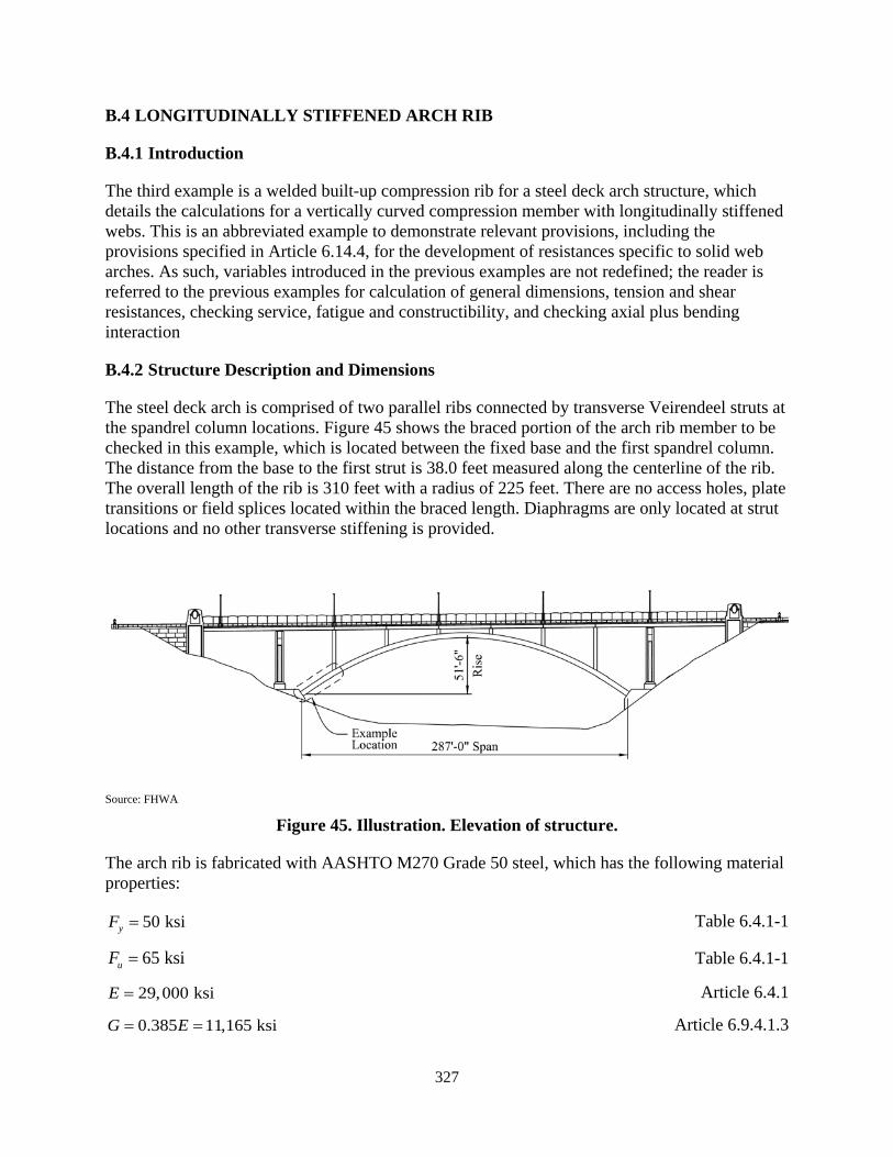
327
B.4 LONGITUDINALLY STIFFENED ARCH RIB
B.4.1 Introduction
The third example is a welded built-up compression rib for a steel deck arch structure, which details the calculations for a vertically curved compression member with longitudinally stiffened webs. This is an abbreviated example to demonstrate relevant provisions, including the provisions specified in Article 6.14.4, for the development of resistances specific to solid web arches. As such, variables introduced in the previous examples are not redefined; the reader is referred to the previous examples for calculation of general dimensions, tension and shear resistances, checking service, fatigue and constructibility, and checking axial plus bending interaction
B.4.2 Structure Description and Dimensions
The steel deck arch is comprised of two parallel ribs connected by transverse Veirendeel struts at the spandrel column locations. Figure 45 shows the braced portion of the arch rib member to be checked in this example, which is located between the fixed base and the first spandrel column. The distance from the base to the first strut is 38.0 feet measured along the centerline of the rib. The overall length of the rib is 310 feet with a radius of 225 feet. There are no access holes, plate transitions or field splices located within the braced length. Diaphragms are only located at strut locations and no other transverse stiffening is provided.
Source: FHWA
Figure 45. Illustration. Elevation of structure.
The arch rib is fabricated with AASHTO M270 Grade 50 steel, which has the following material properties:
50 ksiyF = Table 6.4.1-1
65 ksiuF = Table 6.4.1-1
29,000 ksiE = Article 6.4.1
0.385 11,165 ksiG E= = Article 6.9.4.1.3
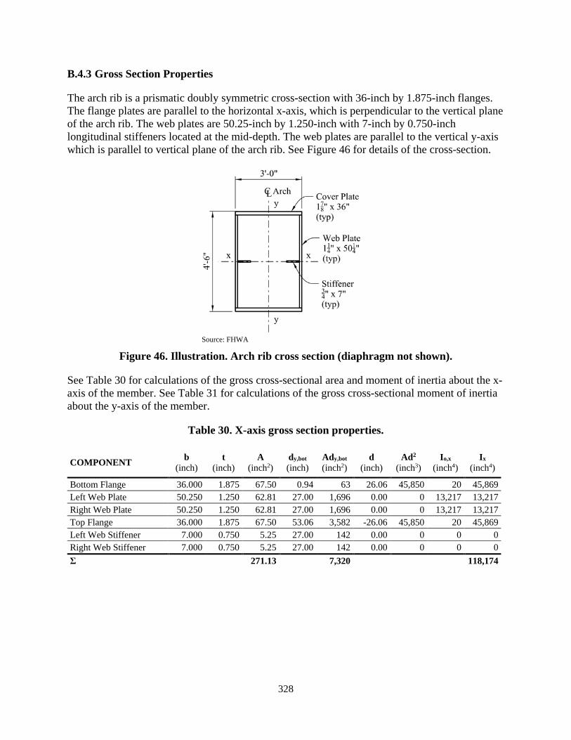
328
B.4.3 Gross Section Properties
The arch rib is a prismatic doubly symmetric cross-section with 36-inch by 1.875-inch flanges. The flange plates are parallel to the horizontal x-axis, which is perpendicular to the vertical plane of the arch rib. The web plates are 50.25-inch by 1.250-inch with 7-inch by 0.750-inch longitudinal stiffeners located at the mid-depth. The web plates are parallel to the vertical y-axis which is parallel to vertical plane of the arch rib. See Figure 46 for details of the cross-section.
Source: FHWA
Figure 46. Illustration. Arch rib cross section (diaphragm not shown).
See Table 30 for calculations of the gross cross-sectional area and moment of inertia about the x-axis of the member. See Table 31 for calculations of the gross cross-sectional moment of inertia about the y-axis of the member.
Table 30. X-axis gross section properties.
COMPONENT b (inch)
t (inch)
A (inch2)
dy,bot (inch)
Ady,bot (inch2)
d (inch)
Ad2 (inch3)
Io,x (inch4)
Ix (inch4)
Bottom Flange 36.000 1.875 67.50 0.94 63 26.06 45,850 20 45,869 Left Web Plate 50.250 1.250 62.81 27.00 1,696 0.00 0 13,217 13,217 Right Web Plate 50.250 1.250 62.81 27.00 1,696 0.00 0 13,217 13,217 Top Flange 36.000 1.875 67.50 53.06 3,582 -26.06 45,850 20 45,869 Left Web Stiffener 7.000 0.750 5.25 27.00 142 0.00 0 0 0 Right Web Stiffener 7.000 0.750 5.25 27.00 142 0.00 0 0 0 Σ 271.13 7,320 118,174
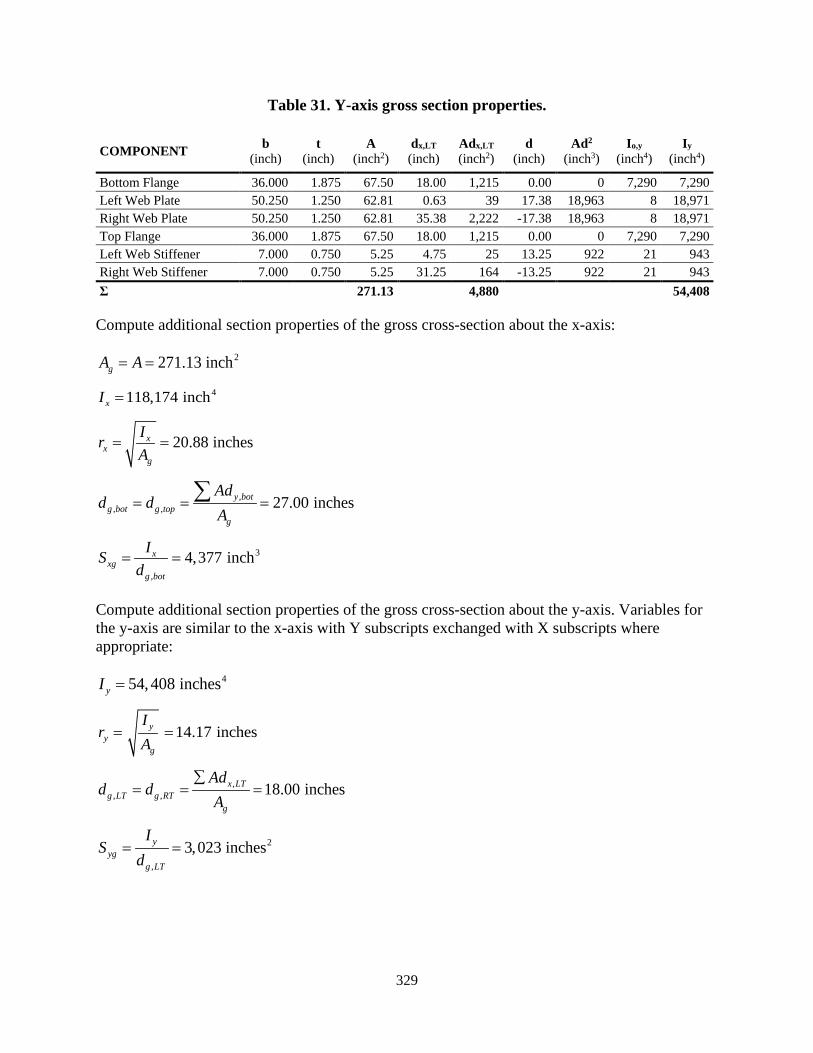
329
Table 31. Y-axis gross section properties.
COMPONENT b (inch)
t (inch)
A (inch2)
dx,LT (inch)
Adx,LT (inch2)
d (inch)
Ad2 (inch3)
Io,y (inch4)
Iy (inch4)
Bottom Flange 36.000 1.875 67.50 18.00 1,215 0.00 0 7,290 7,290 Left Web Plate 50.250 1.250 62.81 0.63 39 17.38 18,963 8 18,971 Right Web Plate 50.250 1.250 62.81 35.38 2,222 -17.38 18,963 8 18,971 Top Flange 36.000 1.875 67.50 18.00 1,215 0.00 0 7,290 7,290 Left Web Stiffener 7.000 0.750 5.25 4.75 25 13.25 922 21 943 Right Web Stiffener 7.000 0.750 5.25 31.25 164 -13.25 922 21 943 Σ 271.13 4,880 54,408
Compute additional section properties of the gross cross-section about the x-axis:
2271.13 inchgA A= =
4118,174 inchxI =
20.88 inchesxx
g
IrA
= =
,, , 27.00 inchesy bot
g bot g topg
Add d
A= = =∑
3
,
4,377 inchxxg
g bot
ISd
= =
Compute additional section properties of the gross cross-section about the y-axis. Variables for the y-axis are similar to the x-axis with Y subscripts exchanged with X subscripts where appropriate:
454,408 inchesyI =
14.17 inchesyy
g
Ir
A= =
,, , 18.00 inchesx LT
g LT g RTg
Add d
A∑
= = =
2
,
3,023 inchesyyg
g LT
IS
d= =

330
B.4.4 Resistance Calculations
Compute the factored resistance for individual force effects including compression and bending about both principal axes.
B.4.4.1 Solid Web Arch Requirements
The rib is a solid web arch member and must satisfy the requirements of Article 6.14.4. The requirements in this section are in addition to those shown in the compression and flexure flowcharts of Appendix A.
B.4.4.1.1 General
Article 6.14.4.1 specifies the following requirements:
• Longitudinal stiffeners are generally not to be employed for curved flanges of conventional arch ribs to increase the slenderness of the plate. The axial force developed in the curved stiffener acting through the vertical curvature of the arch rib induces a radial force from the longitudinal stiffeners, which must be transferred by the flange plate and/or transverse stiffener to the webs of the arch rib as discussed in Section 3.5.2.1. If used, the effects on the longitudinal stiffener and transverse bending of the flange must be assessed when computing the compression strength of the longitudinal stiffener struts, Pns, as well as the connection forces between the longitudinal and transverse stiffeners. Longitudinally stiffened flanges are not used in this example.
• Web longitudinal stiffeners should be flat plates and satisfy the requirements of Article E6.1.3. Tee or angle-section stiffeners on the webs of the arch would exhibit significant bending in the direction normal to the stem or leg attached to the web, due to the action of the axial force in the stiffener acting through the vertical curvature of the arch rib. The web stiffeners used in this example are flat plates.
• If the requirements of Article 6.10.11.3 are not satisfied for longitudinally stiffened webs, the member flexural resistance should be calculated neglecting the longitudinal stiffeners when determining Rb in Article 6.10.1.10.2.
• Without a longitudinal stiffener, the curvature still induces lateral bending in the flange, which reduces the effective yield strength of the curved elements. A reduced minimum yield strength, FyR, must be computed for the horizontal elements (flanges and web longitudinal stiffeners) and used in place of the specified minimum yield strength of the arch rib at all locations of occurrence for the calculation of axial and flexural resistances, and in checking Equation 6.9.4.5-1 at the service and fatigue limit states and for constructibility if the limits of Article 6.14.4.1 are not met. Section 3.5.2.1 provides equations for calculating the reduced yield strength if the limits are not met.
For the portion of the flanges within the clear width between the insides of the webs:
0.47fi
fi
b Rt b≤ Eq. (6.14.4.1-2)
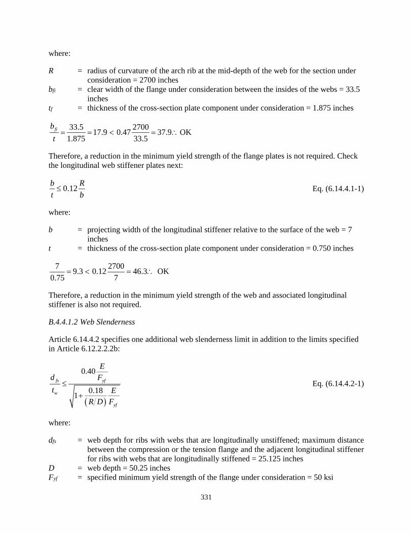
331
where:
R = radius of curvature of the arch rib at the mid-depth of the web for the section under consideration = 2700 inches
bfi = clear width of the flange under consideration between the insides of the webs = 33.5 inches
tf = thickness of the cross-section plate component under consideration = 1.875 inches
33.5 270017.9 0.47 37.9 OK1.875 33.5
fibt= = < = ∴
Therefore, a reduction in the minimum yield strength of the flange plates is not required. Check the longitudinal web stiffener plates next:
0.12b Rt b≤ Eq. (6.14.4.1-1)
where:
b = projecting width of the longitudinal stiffener relative to the surface of the web = 7 inches
t = thickness of the cross-section plate component under consideration = 0.750 inches
7 27009.3 0.12 46.3 OK0.75 7
= < = ∴
Therefore, a reduction in the minimum yield strength of the web and associated longitudinal stiffener is also not required.
B.4.4.1.2 Web Slenderness
Article 6.14.4.2 specifies one additional web slenderness limit in addition to the limits specified in Article 6.12.2.2.2b:
( )
0.40
0.181
fs yf
w
yf
Ed Ft E
R D F
≤+
Eq. (6.14.4.2-1)
where:
dfs = web depth for ribs with webs that are longitudinally unstiffened; maximum distance between the compression or the tension flange and the adjacent longitudinal stiffener for ribs with webs that are longitudinally stiffened = 25.125 inches
D = web depth = 50.25 inches Fyf = specified minimum yield strength of the flange under consideration = 50 ksi

332
tw = web thickness = 1.25 inches
( )
29,0000.4025.125 5020.1 135.2 OK1.25 0.18 29,0001
2,700 50.25 50
= ≤ = ∴+
B.4.4.1.3 Moment Amplification
Article 6.14.4.3 points to the calculation of the approximate moment magnification factor in Article 4.5.3.2.2c for bending about the axis perpendicular to the plane of the vertical curvature.
B.4.4.1.4 Nominal Compression Resistance
For solid web arches, Article 6.14.4.4 applies to the calculation of the elastic critical flexural buckling compression resistance. For in-plane buckling, the Article references the approximate method for calculating the value of K for arches in Article 4.5.3.2.2c. Additionally, for out-of-plan buckling, the Article specifies the use of Article 4.6.2.5 considering the lateral framing for the calculation of the out-of-plane buckling resistance in lieu of a more rigorous buckling analysis.
B.4.4.1.5 Nominal Flexural Resistance
The nominal flexural resistance of noncomposite arch ribs is to be determined using the provisions of Article 6.12, as applicable. The developed unbraced length along the vertical curve between the brace points, Ldb, is to be used for the unbraced length Lb. The reduction of the lateral torsional buckling resistance due to the vertical curvature of the arch rib is to be considered. Following Article 6.14.4.5 for box-section arch ribs with Ldb/R greater than 0.20, subjected to bending moments causing compression on the flange farthest from the center of curvature of the rib, where R is the minimum radius of curvature of the arch rib measured to the mid-depth of the web, the moment gradient modifier, Cb, may be multiplied by 0.90 in lieu of a more refined buckling analysis. Check if this provision applies to this example:
456/ 0.17 0.202,700dbL R = = <
Therefore, the lateral torsional buckling flexural resistance will not be reduced by a factor of 0.90.
B.4.4.1.6 Combined Axial Compression or Tension with Flexure and Flexural and/or Torsional Shear
Article 6.14.4.6 specifies that the interaction between axial compression or tension resistances, flexural resistances, and flexural shear and/or torsion is to be considered as specified in Articles 6.9.2.2 and 6.8.2.3, as applicable.
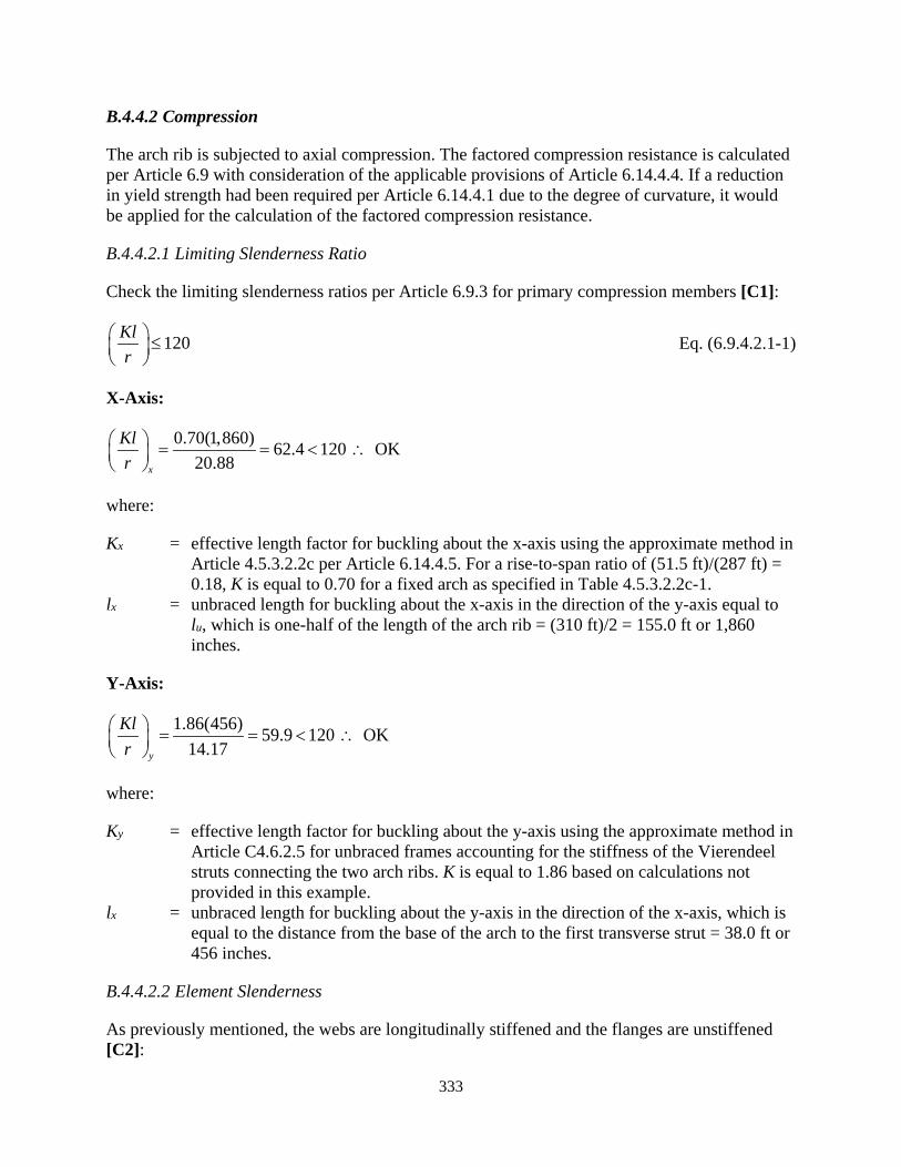
333
B.4.4.2 Compression
The arch rib is subjected to axial compression. The factored compression resistance is calculated per Article 6.9 with consideration of the applicable provisions of Article 6.14.4.4. If a reduction in yield strength had been required per Article 6.14.4.1 due to the degree of curvature, it would be applied for the calculation of the factored compression resistance.
B.4.4.2.1 Limiting Slenderness Ratio
Check the limiting slenderness ratios per Article 6.9.3 for primary compression members [C1]:
120Klr
≤
Eq. (6.9.4.2.1-1)
X-Axis:
0.70(1,860) 62.4 120 OK20.88x
Klr
= = < ∴
where:
Kx = effective length factor for buckling about the x-axis using the approximate method in Article 4.5.3.2.2c per Article 6.14.4.5. For a rise-to-span ratio of (51.5 ft)/(287 ft) = 0.18, K is equal to 0.70 for a fixed arch as specified in Table 4.5.3.2.2c-1.
lx = unbraced length for buckling about the x-axis in the direction of the y-axis equal to lu, which is one-half of the length of the arch rib = (310 ft)/2 = 155.0 ft or 1,860 inches.
Y-Axis:
1.86(456) 59.9 120 OK14.17y
Klr
= = < ∴
where:
Ky = effective length factor for buckling about the y-axis using the approximate method in Article C4.6.2.5 for unbraced frames accounting for the stiffness of the Vierendeel struts connecting the two arch ribs. K is equal to 1.86 based on calculations not provided in this example.
lx = unbraced length for buckling about the y-axis in the direction of the x-axis, which is equal to the distance from the base of the arch to the first transverse strut = 38.0 ft or 456 inches.
B.4.4.2.2 Element Slenderness
As previously mentioned, the webs are longitudinally stiffened and the flanges are unstiffened [C2]:
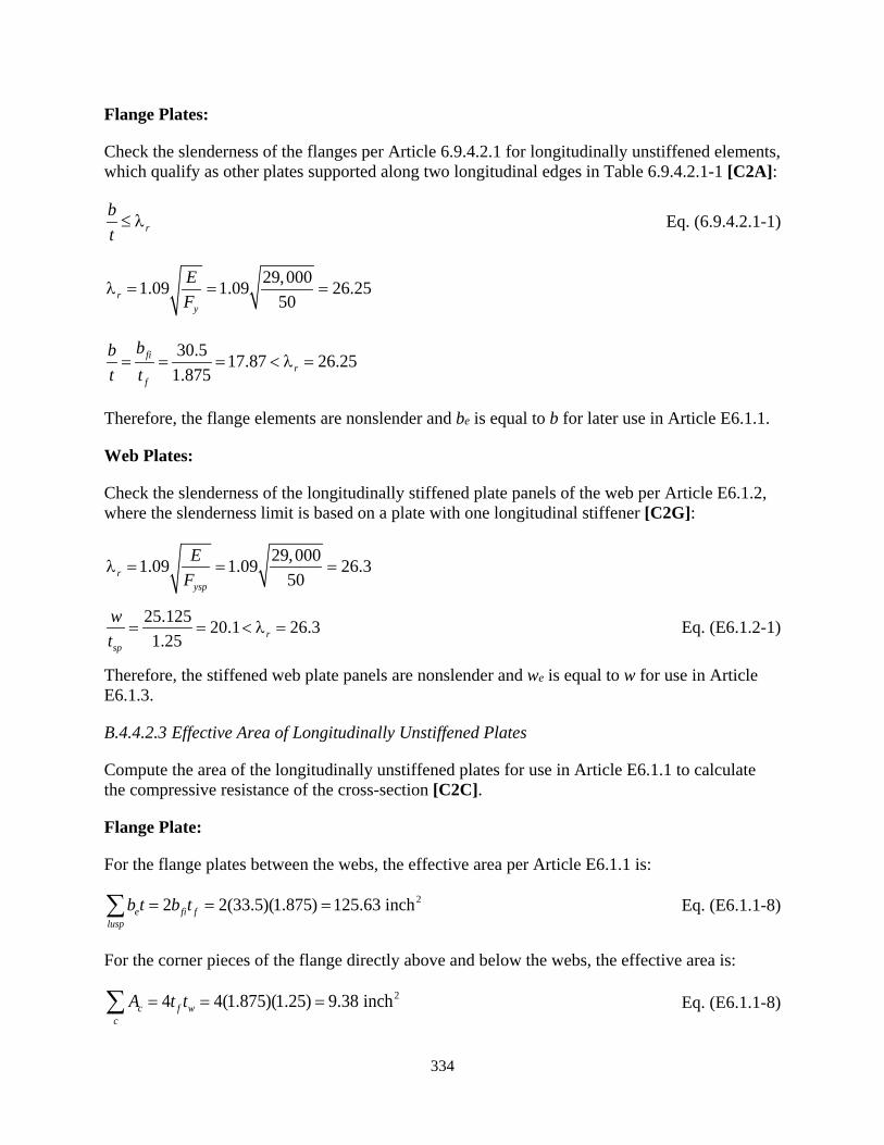
334
Flange Plates:
Check the slenderness of the flanges per Article 6.9.4.2.1 for longitudinally unstiffened elements, which qualify as other plates supported along two longitudinal edges in Table 6.9.4.2.1-1 [C2A]:
rbt≤ λ Eq. (6.9.4.2.1-1)
29,0001.09 1.09 26.2550r
y
EF
λ = = =
30.5 17.87 26.251.875
fir
f
bbt t= = = < λ =
Therefore, the flange elements are nonslender and be is equal to b for later use in Article E6.1.1.
Web Plates:
Check the slenderness of the longitudinally stiffened plate panels of the web per Article E6.1.2, where the slenderness limit is based on a plate with one longitudinal stiffener [C2G]:
29,0001.09 1.09 26.350r
ysp
EF
λ = = =
25.125 20.1 26.31.25 r
sp
wt
= = < λ = Eq. (E6.1.2-1)
Therefore, the stiffened web plate panels are nonslender and we is equal to w for use in Article E6.1.3.
B.4.4.2.3 Effective Area of Longitudinally Unstiffened Plates
Compute the area of the longitudinally unstiffened plates for use in Article E6.1.1 to calculate the compressive resistance of the cross-section [C2C].
Flange Plate:
For the flange plates between the webs, the effective area per Article E6.1.1 is:
22 2(33.5)(1.875) 125.63 inche fi flusp
b t b t= = =∑ Eq. (E6.1.1-8)
For the corner pieces of the flange directly above and below the webs, the effective area is:
24 4(1.875)(1.25) 9.38 inchc f wc
A t t= = =∑ Eq. (E6.1.1-8)

335
B.4.4.2.4 Effective Area of Longitudinally Stiffened Plates
With the effective areas of the longitudinally unstiffened plate elements calculated, compute the effective compression area of the longitudinally stiffened webs per Article E6.1.3 [C2D].
( ) ( )3 3
32 2
(1.250) 0.179 inch12 1 12 1 (0.3)
spp
tI = = =
−ν − Eq. (E6.1.3-7)
27(0.750) 5.25 inchess s sA b t= = =
25.25 25.125(1.250) 36.66 inchgs s spA A wt= + = + = Eq. (E6.1.3-10)
2 225.125(1.25) 75.25 1.252 2 2 2 1.22 inches36.66
sp sps sp
agsgs
wt bA t
dA
+ + + + = = =
2 23 3
23 3
24
12 12 2 2
25.125(1.25) 0.75(7) 1.2525.125(1.25) 1.2212 12 2
75.25 1.25 1.22 102.1 inch2
sp sps s ss sp ags s sp ags
wt tt b bI wt d A t d = + + − + + −
= + + −
+ + − =
1 4 1 4102.1 109.7 inches
25.125(0.179)s
cp
IlwI
= = =
Eq. (E6.1.3-8)
min( , ) min(109.7, 456) 109.7 inchescl l a= = =
If transverse stiffeners were used to increase the compression capacity of the flange, the spacing would need to be less than lc, which is 109.7 inches to provide an increase in capacity. The diaphragm spacing is 456 inches. Transverse stiffeners spaced less than 109.7 inches to increase the compression capacity are not required for this cross-section.
25.25 25.125(1.25) 36.66 inches s e spA A w t= + = + = Eq. (E6.1.3-9)
225.125 (1.25) 15.70 inch2 2gR spwA t= = = Eq. (E6.1.3-14)
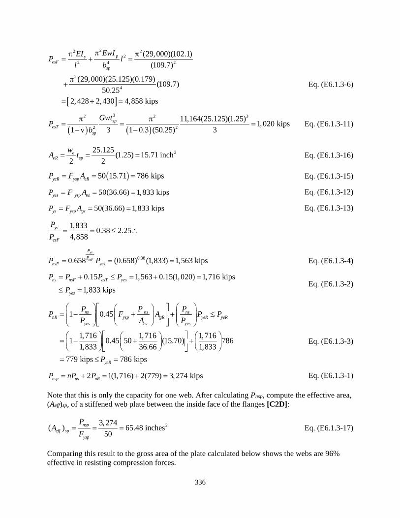
336
[ ]
22 22
2 4 2
2
4
(29,000)(102.1)(109.7)
(29,000)(25.125)(0.179) (109.7)50.25
2,428 2,430 4,858 kips
psesF
sp
EwIEIP ll b
ππ π= + =
π+
= + =
Eq. (E6.1.3-6)
( ) ( )
32 2 3
2 2
11,164(25.125)(1.25) 1,020 kips1 3 1 0.3 (50.25) 3
spesT
sp
GwtP
bπ π
= = =−ν −
Eq. (E6.1.3-11)
225.125 (1.25) 15.71 inch2 2
eeR sp
wA t= = = Eq. (E6.1.3-16)
( )50 15.71 786 kipsyeR ysp eRP F A= = = Eq. (E6.1.3-15)
50(36.66) 1,833 kipsyes ysp esP F A= = = Eq. (E6.1.3-12)
50(36.66) 1,833 kipsys ysp gsP F A= = = Eq. (E6.1.3-13)
1,833 0.38 2.254,858
ys
esF
PP
= = ≤ ∴
0.380.658 (0.658) (1,833) 1,563 kipsys
esF
PP
nsF yesP P= = = Eq. (E6.1.3-4)
0.15 1,563 0.15(1,020) 1,716 kips1,833 kips
ns nsF esT yes
yes
P P P PP
= + ≤ = + =
≤ = Eq. (E6.1.3-2)
1 0.45
1,716 1,716 1,7161 0.45 50 (15.70) 7861,833 36.66 1,833
779 kips 786 kips
ns ns nsnR ysp gR yeR yeR
yes es yes
yeR
P P PP F A P PP A P
P
= − + + ≤
= − + + = ≤ =
Eq. (E6.1.3-3)
2 1(1,716) 2(779) 3,274 kipsnsp ns nRP nP P= + = + = Eq. (E6.1.3-1)
Note that this is only the capacity for one web. After calculating Pnsp, compute the effective area, (Aeff)sp, of a stiffened web plate between the inside face of the flanges [C2D]:
23, 274( ) 65.48 inches50
nspeff sp
ysp
PA
F= = = Eq. (E6.1.3-17)
Comparing this result to the gross area of the plate calculated below shows the webs are 96% effective in resisting compression forces.
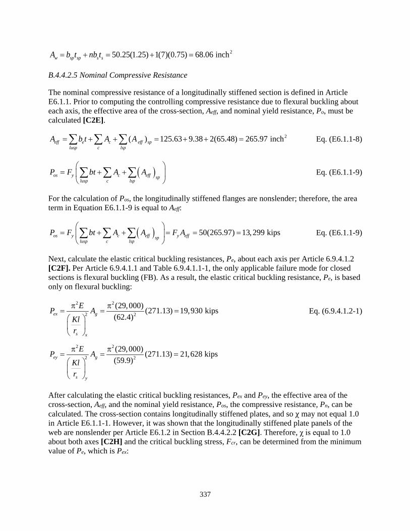
337
250.25(1.25) 1(7)(0.75) 68.06 inchw sp sp s sA b t nb t= + = + =
B.4.4.2.5 Nominal Compressive Resistance
The nominal compressive resistance of a longitudinally stiffened section is defined in Article E6.1.1. Prior to computing the controlling compressive resistance due to flexural buckling about each axis, the effective area of the cross-section, Aeff, and nominal yield resistance, Po, must be calculated [C2E].
2( ) 125.63 9.38 2(65.48) 265.97 incheff e c eff splusp c lsp
A b t A A= + + = + + =∑ ∑ ∑ Eq. (E6.1.1-8)
( )os y c eff splusp c lsp
P F bt A A
= + + ∑ ∑ ∑ Eq. (E6.1.1-9)
For the calculation of Pos, the longitudinally stiffened flanges are nonslender; therefore, the area term in Equation E6.1.1-9 is equal to Aeff:
( ) 50(265.97) 13,299 kipsos y c eff y effsplusp c lsp
P F bt A A F A
= + + = = = ∑ ∑ ∑ Eq. (E6.1.1-9)
Next, calculate the elastic critical buckling resistances, Pe, about each axis per Article 6.9.4.1.2 [C2F]. Per Article 6.9.4.1.1 and Table 6.9.4.1.1-1, the only applicable failure mode for closed sections is flexural buckling (FB). As a result, the elastic critical buckling resistance, Pe, is based only on flexural buckling:
2 2
2 2
(29,000) (271.13) 19,930 kips(62.4)ex g
s x
EP AKlr
π π= = =
Eq. (6.9.4.1.2-1)
2 2
2 2
(29,000) (271.13) 21,628 kips(59.9)ey g
s y
EP AKlr
π π= = =
After calculating the elastic critical buckling resistances, Pex and Pey, the effective area of the cross-section, Aeff, and the nominal yield resistance, Pos, the compressive resistance, Pn, can be calculated. The cross-section contains longitudinally stiffened plates, and so χ may not equal 1.0 in Article E6.1.1-1. However, it was shown that the longitudinally stiffened plate panels of the web are nonslender per Article E6.1.2 in Section B.4.4.2.2 [C2G]. Therefore, χ is equal to 1.0 about both axes [C2H] and the critical buckling stress, Fcr, can be determined from the minimum value of Pe, which is Pex:

338
13,299 0.667 2.25 therefore:19,930
os
ex
PP
= = ≤
( )0.6670.658 0.658 50 37.8 ksios
e
PP
cr yF F
= = =
[C2H] Eq. (E6.1.1-6)
The nominal compression resistance of the member [C2J]:
1.0(37.8)(265.97) 10,054 kipsnx cr effP F A= χ = = Eq. (E6.1.1-1))
For comparison, the nominal yield resistance, Po = AgFy, is 13,556 kips. The member is 74% effective in resisting compression forces, with the major portion of the reduction due to global buckling.
B.4.4.2.6 Longitudinal Stiffener Design
Longitudinal stiffeners used to increase compression capacity of stiffened plates are to be designed per Article E6.1.4. The web longitudinal stiffeners are the same yield strength as the web plate and are structurally continuous over the length of the member. Check the slenderness of the stiffeners per Article E6.1.4 [C12K]:
rbt≤ λ Eq. (E6.1.4-1)
7 29,0009.33 0.45 0.45 10.84 OK0.75 50r
y
b Et F= = < λ = = = ∴
Because the bsp/t of the stiffened plates exceeds 90, the stiffness requirement for self-weight in Article E6.1.4 is not applicable.
The stiffener does not serve as a longitudinal stiffener for a web plate in flexure in the calculation of Rb, or for the shear strength of a stiffened web with transverse stiffeners spaced at 2D or less; therefore, it does not need to satisfy the provisions of Article 6.10.11.3 per Section 3.2.2.2.
B.4.4.2.7 Transverse Stiffener Design
The diaphragms are spaced further apart than the characteristic length, lc, of the longitudinal stiffeners. Therefore, there are no transverse stiffeners used to reduce the buckling length of the longitudinal stiffeners and no design per Article E6.1.5 is required [C2K]. However, the diaphragms are subjected to externally applied loads (from the transverse struts and spandrel columns) and potential cross-sectional distortion forces, which should be considered in the design but are not covered as a part of this example.
B.4.4.2.8 Factored Compression Resistance
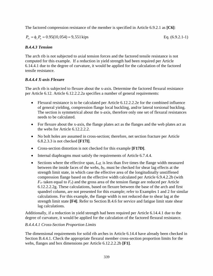
339
The factored compression resistance of the member is specified in Article 6.9.2.1 as [C6]:
0.95(10,054) 9,551 kipsrc c nP P= φ = = Eq. (6.9.2.1-1)
B.4.4.3 Tension
The arch rib is not subjected to axial tension forces and the factored tensile resistance is not computed for this example. If a reduction in yield strength had been required per Article 6.14.4.1 due to the degree of curvature, it would be applied for the calculation of the factored tensile resistance.
B.4.4.4 X-axis Flexure
The arch rib is subjected to flexure about the x-axis. Determine the factored flexural resistance per Article 6.12. Article 6.12.2.2.2a specifies a number of general requirements:
• Flexural resistance is to be calculated per Article 6.12.2.2.2e for the combined influence of general yielding, compression flange local buckling, and/or lateral torsional buckling. The section is symmetrical about the x-axis, therefore only one set of flexural resistances needs to be calculated.
• For flexure about the x-axis, the flange plates act as the flanges and the web plates act as the webs for Article 6.12.2.2.2.
• No bolt holes are assumed in cross-section; therefore, net section fracture per Article 6.8.2.3.3 is not checked [F17I].
• Cross-section distortion is not checked for this example [F17D].
• Internal diaphragms must satisfy the requirements of Article 6.7.4.4.
• Sections where the effective span, Leff, is less than five times the flange width measured between the inside faces of the webs, bfi, must be checked for shear lag effects at the strength limit state, in which case the effective area of the longitudinally unstiffened compression flange based on the effective width calculated per Article 6.9.4.2.2b (with Fcr taken equal to Fy) and the gross area of the tension flange are reduced per Article 6.12.2.2.2g. These calculations, based on flexure between the base of the arch and first spandrel column, are not presented for this example; refer to Examples 1 and 2 for similar calculations. For this example, the flange width is not reduced due to shear lag at the strength limit state [F4]. Refer to Section B.4.6 for service and fatigue limit state shear lag calculations.
Additionally, if a reduction in yield strength had been required per Article 6.14.4.1 due to the degree of curvature, it would be applied for the calculation of the factored flexural resistance.
B.4.4.4.1 Cross-Section Proportion Limits
The dimensional requirements for solid rib arches in Article 6.14.4 have already been checked in Section B.4.4.1. Check the appropriate flexural member cross-section proportion limits for the webs, flanges and box dimensions per Article 6.12.2.2.2b [F1].

340
Webs:
The web plates are stiffened at the mid-height; however, the longitudinal stiffener is not designed per Article 6.10.11.3 with transverse stiffeners spaced at a distance of 2D or less, or considered in the calculation of Rb as discussed in Section 3.2.2.2. Therefore, consider the web to be longitudinally unstiffened for the purposes of Article 6.12.2.2.2b:
50.25 40.2 150 OK1.25w
Dt
= = ≤ ∴ Eq. (6.12.2.2.2b-1)
Flanges:
The top and bottom flanges of the doubly symmetric section are longitudinally unstiffened and subjected to tension and compression. Check appropriate limit:
33.5 17.9 90 OK1.875
fi
f
bt
= = ≤ ∴ Eq. (6.12.2.2.2b-3)
Box Dimensions:
Check the outside dimensions of the box:
50.25 8.375 inches OK36 in es6
ch6foDb = ≥ = = ∴ Eq. (6.12.2.2.2b-5)
Minimum Plate Thickness:
Article 6.12.2.2.2b specifies that the thickness of compression and tension flanges corresponding to the box section principal axis subjected to the larger bending moment should not be less than the thickness of the webs. For the arch rib, the bending about the x-axis is the dominant direction. The flanges (1.875 inches) are thicker than the webs (1.250 inches). Additionally, the thickness of the compression and tension flanges is not to be less than 0.500 inches. The thickness of the flanges about both axes of bending exceed this limit. Finally, the discussion in Section 3.2.2.2 for flexure suggests a minimum plate thickness of 0.750 inches for flange plates subjected to significant bending stresses, which is exceeded by the arch rib flanges.

341
B.4.4.4.2 Classification of Sections
Article 6.12.2.2.2c defines the web plastification factor for the compression flange, Rpc, the web load-shedding factor, Rb, and the compression-flange slenderness factor, Rf, based on web and compression flange slenderness values for longitudinally unstiffened compression flanges.
The equations in Article 6.12.2.2.2c are based on section properties using the effective width of the compression flange, including the depth of web in compression in the elastic range, Dce, the depth of the web in compression at the plastic moment, Dcpe, the yield moment with respect to the compression flange, Myce, and the plastic moment, Mpe.
Because the compression flange is nonslender [F3], these variables are equal to those computed using the gross section [F4]. Additionally, because the member is symmetric about the x-axis, Dce is equal to Dcpe and the section modulus Sxte is the same as Sxce. Since Sxte ≥ Sxce, early nominal yielding in tension does not need to be considered per Article 6.12.2.2.2d [F5]. Refer to Section B.4.3 for x-axis gross cross-sectional properties. Compute Dce, Dcpe, Myce and Mpe as defined in Article 6.12.2.2.2c [F6].
50.25 25.125 inches2 2ceDD = = =
( )( )50.0 4,37718,238 kip-ft
12yce yc xceM F S= = =
As shown below, the web is compact; therefore, calculate the plastic moment, Mpe, using Case I in Table D6.1-2 for negative moment with deck reinforcement parameters set to zero in order to determine Rpc. The nomenclature assumes the bottom flange and lower portion of the web are in compression. Per Section 3.2.2.3, the longitudinal stiffeners are ignored for the computation of Mpe. Compute Dcpe and Mpe:
( )( )( )50.0 36 1.875 3,375 kipsc yc c cP F b t= = =
( )( )( )50.0 36 1.875 3,375 kipst yt t tP F b t= = =
( ) ( )( )( )( )2 50.0 50.25 2 1.25 6,281 kipsw yw wP F D t= = =
12
c t
w
P PDYP
− = +
Table D6.1-2 Case I
50.25 3,375 3,375 1 25.125 inches2 6,281
Y − = + =
50.25 25.125 25.125 inchescpe ceD D D Y= = − = − =
( )2c
ctd D Y= − +
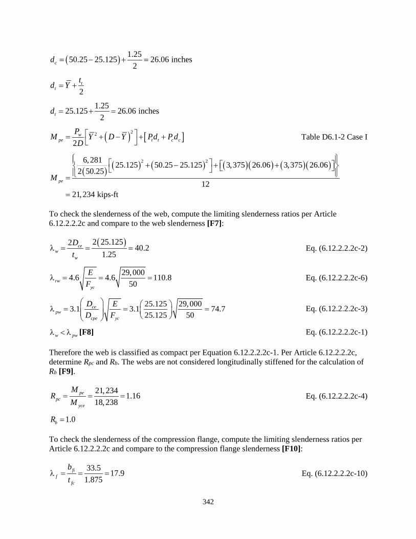
342
( ) 1.2550.25 25.125 26.06 inches2cd = − + =
2t
ttd Y= +
1.2525.125 26.06 inches2td = + =
( ) [ ]22
2w
pe t t c cPM Y D Y Pd P dD = + − + + Table D6.1-2 Case I
( ) ( ) ( ) ( )( ) ( )( )2 26, 281 25.125 3,375 26.06 3,375 26.062 50.25
1221,234 kips-ft
50.25 25.125
peM
+ + + =
−
=
To check the slenderness of the web, compute the limiting slenderness ratios per Article 6.12.2.2.2c and compare to the web slenderness [F7]:
( )2 25.1252 40.2 1.25
cew
w
Dt
λ = = = Eq. (6.12.2.2.2c-2)
29,0004.6 4.6 110.850rw
yc
EF
λ = = = Eq. (6.12.2.2.2c-6)
25.125 29,0003.1 3.1 74.725.125 50
cepw
cpe yc
D ED F
λ = = = Eq. (6.12.2.2.2c-3)
w pwλ < λ [F8] Eq. (6.12.2.2.2c-1)
Therefore the web is classified as compact per Equation 6.12.2.2.2c-1. Per Article 6.12.2.2.2c, determine Rpc and Rb. The webs are not considered longitudinally stiffened for the calculation of Rb [F9].
21,234 1.1618,238
pepc
yce
MR
M= = = Eq. (6.12.2.2.2c-4)
1.0bR =
To check the slenderness of the compression flange, compute the limiting slenderness ratios per Article 6.12.2.2.2c and compare to the compression flange slenderness [F10]:
33.5 17.91.875
fif
fc
bt
λ = = = Eq. (6.12.2.2.2c-10)

343
29,0001.09 1.09 26.350pf r
y
EF
λ = λ = = = Table 6.9.4.2.1-1
Therefore the compression flange is classified as compact per Equation 6.12.2.2.2c-9. Per Article 6.12.2.2.2c, determine Rf [F12]:
1.0fR = Eq. (6.12.2.2.2c-11)
B.4.4.4.3 Nominal Flexural Resistance Based on General Yielding, Compression Flange Local Buckling and Lateral Torsional Buckling
After checking the cross-section proportion limits and classifying the plate elements of the section, the nominal flexural resistance can be calculated per Article 6.12.2.2.2e. Compute the unbraced length limits, Lp and Lr, to determine the appropriate flexural resistance formula [F13]. The braced length of the member for flexure about the x-axis is equal to the distance from the fixed support to the lateral strut connecting the two arch ribs. Article 6.14.4.5 for the nominal flexural resistance of solid web arches specifies the use of Article 6.12, as applicable, for the resistance calculations.
456bL =
2 33.5 2(1.25) 36.0 inchesfo fi wb b t= + = + =
36 1.25 34.75 inchesm fo wb b t= − = − =
1.875 1.87550.25 52.1252 2 2 2fc ft
m
t th D= + + = + + =
234.75(52.1 n25) 1,811 i cheso m mA b h= ==
( ) ( )2 34.75 2 52.1252 2 120.51.875 1.25
m m m
f w
b b ht t t
∑ = + = + =
( )2244 1,8114 108,870 inches
120.5o
m
AJ bt
= = =∑
Eq. (6.12.2.2.2e-3)
( )( ) ( )( )( )
108,870 271.130.10 0.10 29,000 14.2
18,238 121,022 inches
p yyce
JAL ErM
= =
=
Eq. (6.12.2.2.2e-4)
( )0.5 0.5 50.0 25.0 ksiyr ycF F= = =

344
( )( ) ( )( )( )( )
108,870 271.130.60 0.60 29,000 14.2
25.0 4,37712,268 inches
r yyr xce
JAL ErF S
= =
=
Eq. (6.12.2.2.2e-5)
b pL L< [F14]
The braced length, Lb, is less than Lp; therefore, the nominal flexural resistance is calculated per Equation 6.12.2.2.2e-1 [F15]:
eb p fn yccM R R R M= Eq. (6.12.2.2.2e-1)
( )( )( )( )1.00 1.16 1.00 18,238 21,156 kip-ftnM = =
B.4.4.4.4 Factored Flexural Resistance
The arch rib is subjected to flexure about the x-axis. The factored flexural resistance of the member about the x-axis is specified in Article 6.12.1.2.1 as [F16]:
r f nM M= φ Eq. (6.12.1.2.1-1)
( )( )1.00 21,237 21,237 kip-ftrxc r f nM M M= = φ = =
B.4.4.5 Y-axis Flexure
The arch rib is subjected to flexure about the y-axis. Determine the factored flexural resistance per Article 6.12. As discussed in the section for x-axis flexure, Article 6.12.2.2.2a specifies a number of general requirements. Those varying for flexure about the y-axis include:
• Flexural resistance is to be calculated per Article 6.12.2.2.2e for the combined influence of general yielding, compression flange local buckling, and/or lateral torsional buckling. The section is symmetrical about the y-axis, therefore the flexural resistance is the same for positive and negative bending about the y-axis. The web (compression flange) is longitudinally stiffened, therefore Article 6.12.2.2.2d is applicable [F2].
• For flexure about the y-axis, the web plates act as the flanges and the flange plates act as the webs for Article 6.12.2.2.2.
• For shear lag at the strength limit state, the flange width (web plates) is not reduced due to shear lag. These calculations are not presented for this example; refer to Examples 1 and 2 for similar calculations [F2C]. Refer to Section B.4.6 for service and fatigue limit state shear lag calculations.
Additionally, if a reduction in yield strength had been required per Article 6.14.4.1 due to the degree of curvature, it would be applied for the calculation of the factored flexural resistance.
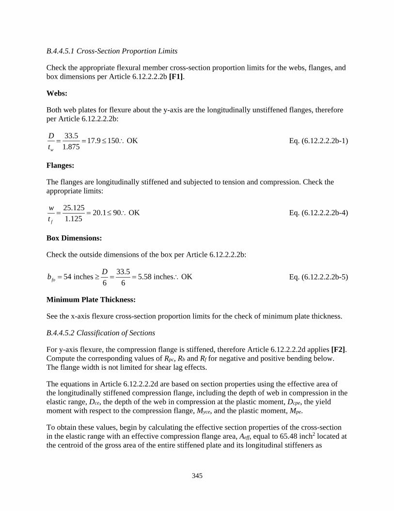
345
B.4.4.5.1 Cross-Section Proportion Limits
Check the appropriate flexural member cross-section proportion limits for the webs, flanges, and box dimensions per Article 6.12.2.2.2b [F1].
Webs:
Both web plates for flexure about the y-axis are the longitudinally unstiffened flanges, therefore per Article 6.12.2.2.2b:
33.5 17.9 150 OK1.875w
Dt
= = ≤ ∴ Eq. (6.12.2.2.2b-1)
Flanges:
The flanges are longitudinally stiffened and subjected to tension and compression. Check the appropriate limits:
25.125 20.1 90 OK1.125f
wt
= = ≤ ∴ Eq. (6.12.2.2.2b-4)
Box Dimensions:
Check the outside dimensions of the box per Article 6.12.2.2.2b:
K33 h.554 ninche 5.58 i c es O6 6
sfoDb ≥ = = ∴= Eq. (6.12.2.2.2b-5)
Minimum Plate Thickness:
See the x-axis flexure cross-section proportion limits for the check of minimum plate thickness.
B.4.4.5.2 Classification of Sections
For y-axis flexure, the compression flange is stiffened, therefore Article 6.12.2.2.2d applies [F2]. Compute the corresponding values of Rpc, Rb and Rf for negative and positive bending below. The flange width is not limited for shear lag effects.
The equations in Article 6.12.2.2.2d are based on section properties using the effective area of the longitudinally stiffened compression flange, including the depth of web in compression in the elastic range, Dce, the depth of the web in compression at the plastic moment, Dcpe, the yield moment with respect to the compression flange, Myce, and the plastic moment, Mpe.
To obtain these values, begin by calculating the effective section properties of the cross-section in the elastic range with an effective compression flange area, Aeff, equal to 65.48 inch2 located at the centroid of the gross area of the entire stiffened plate and its longitudinal stiffeners as

346
computed in Section B.4.4.2.4 per Article E6.1.3 [F2A and F2B]. Calculate the distance of the stiffened plate centroid from the bottom of the section:
250.25(1.25) 1(7)(0.75) 68.06 inchsp fi f s s sA b t n b t= + = + =
( ),
/ 2 ( / 2) 50.25(1.25)(1.25 / 2) 1(7)(0.75)(1.25 7.5 / 2)68.07
0.94 inches
fi f f s s s f se sp
sp
b t t n b t t bd
A
+ + + + = = =
Calculate the effective section properties in Table 32 below by replacing the compression (top) flange between the webs and associated longitudinal stiffeners with the effective area, Aeff,, at the location calculated above [F4C]. Use the total area, Asp, for the tension (bottom flange). The flange widths above and under the webs (corners pieces) are included.
Table 32. Y-axis effective cross-section properties for strength limit state.
COMPONENT b (inch)
t (inch)
A (inch2)
dx,bot (inch)
Adx,bot (inch2)
d (inch)
Ad2 (inch3)
Io,y (inch4)
Iy (inch4)
Bottom Flange (Effective Area)
68.06 0.94 64 16.90 19,430 19,430
Bottom Flange (Corners) 3.750 1.250 4.69 0.63 3 17.21 1,389 1 1,389
Left Web Plate 33.500 1.875 62.81 18.00 1,131 -0.16 2 5,874 5,876 Right Web Plate 33.500 1.875 62.81 18.00 1,131 -0.16 2 5,874 5,876 Top Flange (Effective Area)
65.48 35.06 2,296 -17.22 19,425 19,425
Top Flange (Corners) 3.750 1.250 4.69 35.38 166 -17.54 1,442 1 1,443
Σ 268.54 4,790 53,439
,,
4,790 17.84 inches268.54
x bote bot
Add
A= = =
, , 36 17.84 18.16 inchese top s e botd D d= − = − =
453,439 inchyeI =
3
,
53,439 2,943 inch18.16
yeyce
e top
IS
d= = =
( )50 2,94312,261 kip-ft
12yce yc yceM F S= = =
, 18.16 1.25 16.91 inchesce e top fD d t= − = − =
Per Article 6.12.2.2.2d, determine if Syte < Syce requiring the use of Section 3.2.2.3 to calculate Dce and Myce accounting for early nominal yielding in tension [F2D]:
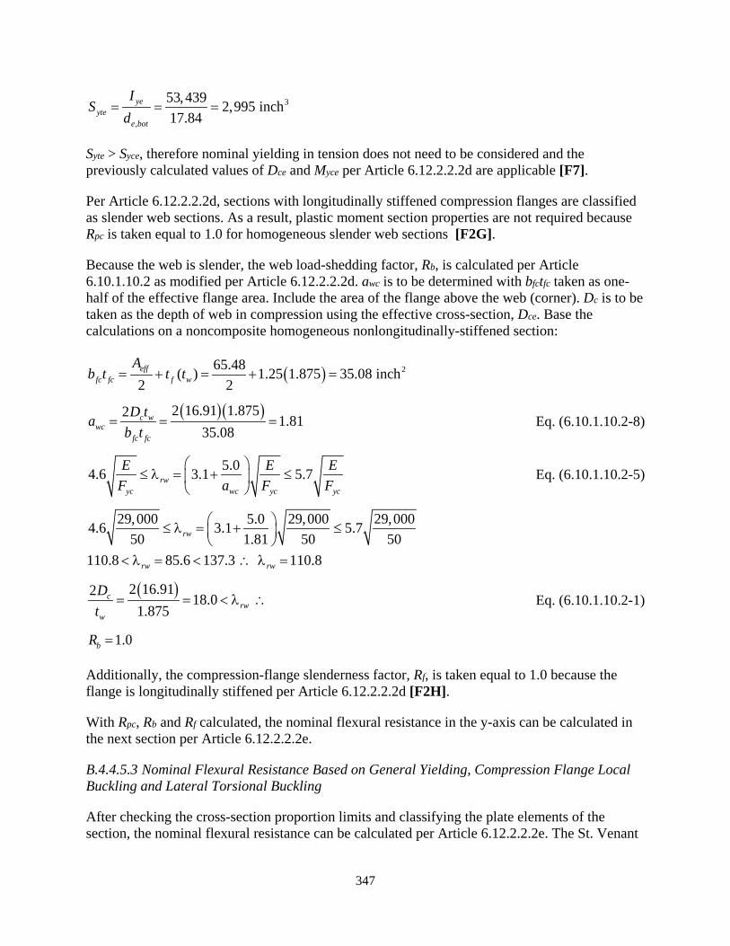
347
3
,
53,439 2,995 inch17.84
yeyte
e bot
IS
d= = =
Syte > Syce, therefore nominal yielding in tension does not need to be considered and the previously calculated values of Dce and Myce per Article 6.12.2.2.2d are applicable [F7].
Per Article 6.12.2.2.2d, sections with longitudinally stiffened compression flanges are classified as slender web sections. As a result, plastic moment section properties are not required because Rpc is taken equal to 1.0 for homogeneous slender web sections [F2G].
Because the web is slender, the web load-shedding factor, Rb, is calculated per Article 6.10.1.10.2 as modified per Article 6.12.2.2.2d. awc is to be determined with bfctfc taken as one-half of the effective flange area. Include the area of the flange above the web (corner). Dc is to be taken as the depth of web in compression using the effective cross-section, Dce. Base the calculations on a noncomposite homogeneous nonlongitudinally-stiffened section:
( ) 265.48( ) 1.25 1.875 35.08 inch2 2eff
fc fc f w
Ab t t t= + = + =
( )( )2 16.91 1.8752 1.8135.08
c wwc
fc fc
D tab t
= = = Eq. (6.10.1.10.2-8)
5.04.6 3.1 5.7rwyc wc yc yc
E E EF a F F
≤ λ = + ≤
Eq. (6.10.1.10.2-5)
29,000 5.0 29,000 29,0004.6 3.1 5.750 1.81 50 50
110.8 85.6 137.3 110.8
rw
rw rw
≤ λ = + ≤
< λ = < ∴ λ =
( )2 16.912 18.0 1.875
crw
w
Dt
= = < λ ∴ Eq. (6.10.1.10.2-1)
1.0bR =
Additionally, the compression-flange slenderness factor, Rf, is taken equal to 1.0 because the flange is longitudinally stiffened per Article 6.12.2.2.2d [F2H].
With Rpc, Rb and Rf calculated, the nominal flexural resistance in the y-axis can be calculated in the next section per Article 6.12.2.2.2e.
B.4.4.5.3 Nominal Flexural Resistance Based on General Yielding, Compression Flange Local Buckling and Lateral Torsional Buckling
After checking the cross-section proportion limits and classifying the plate elements of the section, the nominal flexural resistance can be calculated per Article 6.12.2.2.2e. The St. Venant
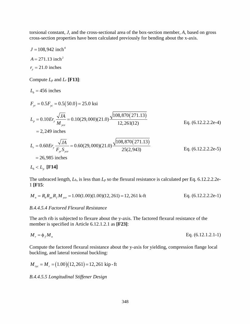
348
torsional constant, J, and the cross-sectional area of the box-section member, A, based on gross cross-section properties have been calculated previously for bending about the x-axis.
4108,942 inchJ = 2271.13 inchA =
21.0 inchesyr =
Compute Lp and Lr [F13]:
456 inchesbL =
( )0.5 0.5 50.0 25.0 ksiyr ycF F= = =
( )108,870 271.130.10 0.10(29,000)(21.0)
12,261(12)2,249 inches
p yyce
JAL ErM
= =
=
Eq. (6.12.2.2.2e-4)
( )108,870 271.130.60 0.60(29,000)(21.0)
25(2,943)26,985 inches
r yyr yce
JAL ErF S
= =
=
Eq. (6.12.2.2.2e-5)
b pL L< [F14]
The unbraced length, Lb, is less than Lp so the flexural resistance is calculated per Eq. 6.12.2.2.2e-1 [F15:
1.00(1.00)(1.00)(12,261) 12,261 k-ftn b pc f yceM R R R M= = = Eq. (6.12.2.2.2e-1)
B.4.4.5.4 Factored Flexural Resistance
The arch rib is subjected to flexure about the y-axis. The factored flexural resistance of the member is specified in Article 6.12.1.2.1 as [F23]:
r f nM M= φ Eq. (6.12.1.2.1-1)
Compute the factored flexural resistance about the y-axis for yielding, compression flange local buckling, and lateral torsional buckling:
( )( )1.00 12,261 12,261 kip - ftryc rM M= = =
B.4.4.5.5 Longitudinal Stiffener Design
349
The longitudinal stiffeners have previously been designed for stiffened plates in compression per Article E6.1.4. However, the stiffeners are not used to satisfy the slenderness requirements for a web with a D/tw greater than 150 and a transverse stiffener spacing less than or equal to 2D; they are also not used to calculate the web load-shedding factor, Rb. Therefore, per Section 3.2.2.2, the stiffeners do not need to be designed to satisfy the provisions of Article 6.10.11.3 [F2I].
B.4.4.5.6 Transverse Stiffener Design
The web plates (flanges for y-axis bending) are not transversely stiffened [F2J].
B.4.4.6 Y-axis Shear
The shear resistance of the cross-section in the direction of the y-axis is not calculated for this example. See Examples 1 and 2 for details of shear resistance calculations in accordance with Article 6.12.1.2.3. In accordance with Section 3.2.2.4, transverse stiffeners are not provided at a spacing of 2D or less and the longitudinal stiffeners are not considered for the calculation of Rb in Article 6.10.1.10.2, therefore the web plates are considered unstiffened. Additionally, the diaphragms are spaced further apart than 3D and as a result, the longitudinally unstiffened webs must be treated as unstiffened per Article 6.10.9.1. Thus, the shear resistance of the webs is based on shear-yielding or shear-buckling as specified for unstiffened webs in Article 6.10.9.2. Finally, if a reduction in yield strength had been required per Article 6.14.4.1 due to the degree of curvature, it does not apply to the calculation of Vn.
B.4.4.7 X-axis Shear
The shear resistance of the cross-section in the direction of the x-axis is not calculated for this example. The flange plates, acting as webs, are unstiffened for shear. See Section B.4.4.6 for more details.
B.4.5 Demand to Capacity and Interaction Checks
The factored forces and demand-to-capacity (D/C) ratios are not provided for this example. See Examples 1 and 2 for details of these calculations.
B.4.5.1 Combined Axial Compression and Flexure
The cross-section is subjected to axial compression and flexure and needs to be checked for interaction per Article 6.9.2.2. These calculations are not provided in this example. Refer to the other examples for details. The following is a list of items to consider when performing the interaction check:
• The section is longitudinally stiffened for flexure about the y-axis; therefore the section is a slender web section and the interaction Equations 6.9.2.2.1-1 and 6.9.2.2.1-2 are not applicable.
• Article 6.9.2.2.1 specifies that moments about each axis should be calculated by a second-order elastic analysis that accounts for the magnification of moment caused by the factored axial load, or the approximate single-step adjustment method specified in Article 4.5.3.2.2b, or a comparable amplification factor based procedure. See Section B.4.4.1.4
350
for Article 6.14.4.4 compression requirements for solid web arches. Article 6.14.4.3 points to the calculation of the approximate moment magnification factor in Article 4.5.3.2.2c for bending about the axis perpendicular to the plane of the vertical curvature [F2D]. Ziemian (2016) should be reviewed concerning the buckling lengths and amplification factors of tied arches. For bending about the other axis, the magnification based on approximate methods should use the effective length factor, K, as described in Article 4.6.2.5 with consideration given to the presence of sideway.
• Article 6.14.4.6 for solid web arches specifies the use of Articles 6.9.2.2 and 6.8.2.3 for combined axial compression or tension with flexure and flexural and/or torsional shear, respectively. If the section is subjected to torsional [C7A and F17A] or flexural shear [C7D and F17E], the axial and flexural resistance reduction factors, ∆, ∆x and ∆y, need to be calculated and applied in accordance with Article 6.9.2.2.2. For an arch rib, Pu/Pr, is typical greater than 0.05. As a result, flexural shear stresses should be included with the torsional shear stresses (if applicable) when computing the reduction factors [C7G and F17G].
• Per Section 3.3.2.1, Pu, Mux, and Muy should be simultaneous factored axial and flexural forces determined by analysis. The maximum axial force, and the separate maximum member moments about each of the cross-section principal axes, x and y, including the second-order effects and irrespective of their location along the member unbraced length, are to be combined together in the applicable equations. This is required to ensure stability. The unbraced length of the member may be different for the axial and flexural results. The commentary in Section 3.3.2.1 provides a detailed discussion of this process and outlines checks that need only be performed on a cross-section by cross-section basis.
B.4.6 Service, Fatigue and Constructibility
For the service and fatigue limit states, the same strength limit state shear lag requirements apply to simple spans and positive moment regions (i.e., no reductions for shear lag about the x- or y-axes in this example). For negative moment regions, when Leff is less than thirty times bfi, Equations 6.12.2.2.2g-2 and 6.12.2.2.2g-3 apply to limit the flange dimensions accordingly for shear lag effects for the calculation of service and fatigue limit state stresses. These calculations are not presented for this example; refer to Examples 1 and 2 for similar calculations. For this example, the flange areas are reduced by 29% due to shear lag at the service limit state for bending about the x-axis. The flange (web plate) areas are reduced by 18% for bending about the y-axis.
For flexural members, Article 6.12.2.2.2f requires the webs to satisfy the service, constructibility and fatigue requirements of Articles 6.10.3.3 and 6.10.5.3 [F19]. Article 6.12.2.2.2f also requires that all noncomposite steel box sections satisfy the stress limit given by Equation 6.12.2.2.2f-1 in order to control permanent deformations. Finally, if the section is a slender web section per Article 6.12.2.2.2c; contains slender longitudinally stiffened plate panels as defined in Article E6.1.2; or the flange slenderness, λf, of a longitudinally unstiffened compression flange exceeds λpf as defined in Article 6.12.2.2.2c, the provisions of Article 6.9.4.5 are also to apply at the service limit state and for constructibility [C8 and F21]. If a reduced yield strength had been required per Article 6.14.4.1 based on the degree of curvature for solid web arches, Fy should be replaced with that reduced value when checking Equation 6.9.4.5-1.

351
Because the cross-section is relatively stout, the requirements of this section should generally be satisfied without requiring modification to the size of the cross-section. See the other examples for details of these calculations.
352
REFERENCES
AASHTO (2017). AASHTO LRFD Bridge Design Specifications, 8th Edition, American Association of State Highway and Transportation Officials, Washington, DC.
AASHTO (2015). AASHTO LRFD Bridge Design Specifications, 7th Edition, American Association of State Highway and Transportation Officials, Washington, DC.
AASHTO (1985). Guide Specifications for Strength Design of Truss Bridges (Load Factor Design), Washington, D.C.
AISC (2016). Specification for Structural Steel Buildings, ANSI/AISC 360-16, American Institute of Steel Construction, Chicago, IL.
AISC (2010). Specification for Structural Steel Buildings, ANSI/AISC 360-10, American Institute of Steel Construction, Chicago, IL.
AISC (1969). Specification for the Design, Fabrication and Erection of Structural Steel for Buildings, American Institute of Steel Construction, New York, NY.
AISI (2016). North American Specification for the Design of Cold-Formed Steel Structural Members, AISI S100-16, American Iron and Steel Institute, Washington, DC.
AISI (2012), North American Specification for the Design of Cold-Formed Steel Structural Members, AISI S100-12, American Iron and Steel Institute, Washington, DC.
AISI (1986). Specification for the Design of Cold-Formed Steel Structural Members, American Iron and Steel Institute, Washington, DC.
ASCE. (2016). Minimum Design Loads and Associated Criteria for Buildings and Other Structures, ASCE/SEI 7-16, American Society of Civil Engineers, Reston, VA.
Baker, J.F., Horne, M.R. and Heyman, J. (1956). The Steel Skeleton, Vol. 2, University Press, Cambridge.
Basler, K. and Thurliman, B. (1961). “Strength of Plate Girders in Bending,” Journal of Structural Division, ASCE, 87(ST6), 153-181.
Beg, D., Kuhlmann, U., Davine, L. and Braun, B. (2010). Design of Plated Structures, Eurocode 3: Design of Steel Structures, Part 1-5: Desgin of Plated Structures, ECCS Eurocode Design Manuals, 1st Ed., 271 pp.
BSI (2000). Steel, Concrete and Composite Bridges, British Standard BS 5400: Part 3, Code of Practice for Design of Steel Bridges, British Standards Institution, London.
CEN (2005). Eurocode 3: Design of Steel Structures, Part 1-1: General Rules and Rules for Buildings, BS EN 1993-1-1:2005: E, Incorporating Corrigendum February 2006, European Committee for Standardization, Brussels, Belgium, 91 pp.
353
CEN (2006a). Eurocode 3: Design of Steel Structures, Part 2: Steel Bridges, Incorporating Corrigendum July 2009, European Committee for Standardization, Brussels, Belgium, 101 pp.
CEN (2006b). Eurocode 3: Design of Steel Structures, Part 1-5: General Rules - Plated Structural Elements, BS EN 1993-1-5:2006: E, Incorporating Corrigendum April 2009, European Committee for Standardization, Brussels, Belgium, 56 pp.
Chandra, V., and Tse, J. (2012). “Design Guidelines for Arch and Cable-Supported Signature Bridges,” Publication No. FHWA-NHI-11-023, Federal Highway Administration, U.S. Department of Transportation, February.
Connor. R., Fisher, J., Gatti, W., Golpalaratnam, V., Kozy, B., Leshko, B., McQuaid, D.L., Medlock, R., Mertz, D., Murphy, T., Patterson, D., Sorenson, O, and Yadlosky, J. (2012), “Manual for Design, Construction, and Maintenance of Orthotropic Steel Deck Bridges,” Publication No. FHWA-IF-12-027, February, 262 pp.
CRC (1960). Guide to Design Criteria for Metal Compression Members, Column Research Council, Engineering Foundation.
CSA Group (2014). S16-14 - Design of Steel Structures, Canadian Standards Association, 222 pp.
Dabrowski, R. (1968). Curved Thin-Walled Girders, Theory and Analysis, Cement and Concrete Association, London.
Daley, A.J., Davis, D.B. and White, D.W. (2016). “Shear Strength of Unstiffened Steel I-Section Members,” Journal of Structural Engineering, ASCE, Published online: Oct. 14, 11 pp.
Darwin, D. (1990). Steel and Composite Beams with Web Openings, Steel Design Guide Series 2, American Institute of Steel Construction, Chicago, IL.
Dowling, P.J., Harding, J.E. and Frieze, P.A. (eds.) (1977). “Steel Plated Structures,” Proceedings of International Conference, Imperial College, Crosby Lockwood, London.
Dowswell, B (2018). Curved Steel. Design Guide, American Institute of Steel Construction, Chicago, IL.
Fan, Z. and Helwig, T.A. (2002). “Distortional Loads and Brace Forces in Steel Box Girders,” Journal of Structural Engineering, 128(6), 710-718.
FHWA (2015). Steel Bridge Design Handbook, Design Example 5: Three-Span Continuous Horizontally Curved Composite Steel Tub-Girder Bridge, Federal Highway Administration, Washington, DC.
Frieze, P.A., and Dowling, P.J. (1979), “Testing of a Wide Girder with Slender Compression Flange Stiffeners under Pronounced Shear Lag Conditions”, CESLIC Rep. BG 49, Imperial College, University of London.
354
Galambos, T.V. (2006). "Reliability of the Member Stability Criteria in the 2005 AISC Specification," Engineering Journal, AISC, 4th Quarter, 257-265.
Galea, Y., and Martin, P.O. (2010). “Longitudinally Stiffened Plates in Eurocode 3: Calculation of the Global Critical Buckling Stress,” Journal of Construction Steel Research, 66(11), 1345-53.
Geschwindner, L.F. and Troemner, M. (2016). “Notes on the AISC 360-16 Provisions for Slender Compression Elements in Compression Members,” Engineering Journal, 3rd Quarter, 137-146.
Goldberg, J.E. and Leve, H.L. (1957). “Theory of Prismatic Folded Plate Structures,” IABSE, Zurich, Switzerland, 16, 59-86.
Haaijer, G. 1981. “Simple Modeling Technique for Distortion Analysis of Steel Box Girders.” Proceedings of the MSC/NASTRAN Conference on Finite Element Methods and Technology, MacNeal/Schwendler Corporation, Los Angeles, CA, March 19-20.
Heins, C.P. and Hall, D.H., (1981). Designers Guide to Steel Box Girder Bridges, Booklet No. 3500, Bethlehem Steel Corporation.
Hendy, C.R. and Murphy, C.J. (2007). Designers’ Guide to EN 1993-2 Eurocode 3: Design of Steel Structures, Part 2: Steel Bridges, Thomas Telford Publishing, London.
Helwig, T.A., Yura, J., Herman, R., Williamson, E., and Li, D. (2007). “Design Guidelines for Steel Trapezoidal Box Girder Systems,” Report No. FHWA/TX-07/0-4307-1, Center for Transportation Research, University of Texas, Austin, TX, 72 pp.
Hildebrand, F.B. and Reissner, E. (1943). “Least Work Analysis of the Problem of Shear Lag in Box Beams,” NACA Technical Note 893.
Höglund, T. (1997), “Shear Buckling Resistance of Steel and Aluminum Plate Girders,” Thin-Walled Structures, 29(1-4), 13-30.
Horne, M.R. (1964). “Safe Loads on I-Section Columns in Structures Designed by Plastic Theory,” Proceedings of the Institution of Civil Engineers, Sept.
Jha, A.P. (2016). “Investigation of the Shear Strength of Built-Up I-Section Members via Test Simulation,” M.S. Thesis, School of Civil and Environmental Engineering, Georgia Institute of Technology, August, 234 pp.
Johansson, B., and Veljkovic, M. (2009). “Review of Plate Buckling Rules in EN 1993-5,” Steel Construction, 2(4), Ernst & Sohn Verlag für Architektur und technische Wissenschaften GmbH & Co. KG, Berlin, p 228.
Johansson, B., Maquoi, R., Sedlacek, G., Muller, C. and Beg, D. (2007). Commentary and Worked Examples to EN 1993-1-5 “Plated Structural Elements”, JRC Scientific and Technical Reports.

355
Johnson, D. L. (1985). "An Investigation into the Interaction of Flanges and Webs in Wide Flange Shapes." Proceedings, SSRC Annual Technical Session, Cleveland, OH, Structural Stability Research Council, Gainesville, FL.
Kaehler, R.C., White, D.W., Kim, Y.D. and Jeong, W.Y. (2018). Frame Design Using Non-Prismatic Members, Steel Design Guide 25, 2nd Ed., American Institute of Steel Construction.
Kanchanalai, T. (1977). “The Design and Behavior of Beam-Columns in Unbraced Steel Frames,” AISI Project No. 189, Report No. 2. American Iron and Steel Institute, Washington, DC, Civil Engineering/Structures Research Lab, University of Texas, Austin, TX, October.
King, C.M. (2017). “A New Design Method for Longitudinally Stiffened Plates.” Proceedings of the Annual Stability Conference, Structural Stability Research Council, San Antonio, TX, March.
King, C. and Brown, D. (2001). Design of Curved Steel, SCI Publication P281, Steel Construction Institute, Silwood Park, Ascot, Berkshire, 112 pp.
Lokhande, A.M. and White, D.W. (2018). “Improved Characterization of the Flexural and Axial Compressive Resistance of Welded Steel Box-Section Members,” Structural Engineering Report, School of Civil and Environmental Engineering, Georgia Institute of Technology, Atlanta, GA.
Moffatt, K.R., and Dowling, P.J. (1975). “Shear Lag in Steel Box Girder Bridges,” The Structural Engineer, 53, p. 439-447.
Moffatt, K.R., and Dowling, P.J. (1976). “Discussion”, The Structural Engineer, 54, p. 285-297
Murray, N. W. (1973). “Buckling of Stiffened Panel Loaded Axially and in Bending.” Structural Engineering, 51(8), 285–301.
Naumes, J., Feldmann, M., and Sedlacek, G. (2009). “Demonstration of the Common Basis of Method 1 (Effective Width Approach) and Method 2 (Stress Limit Approach) for the Plate buckling Assessment of Built-up Steel Components According to Eurocode 3-Part 1-5,” Stahlbau, 78(3), 139-147 (in German).
Nettleton, D.A. (1977). Arch Bridges, Bridge Division, Office of Engineering, Federal Highway Administration, U.S. Department of Transportation, Washington. DC.
Peköz, T. (1987). “Development of a Unified Approach to the Design of Cold-Formed Steel Members,” Report CF87-1, American Iron and Steel Institute, Washington, DC.
Rogers, N.A. and Dwight, J.B. (1976). “Outstand Strength,” Paper 12, Proceedings of the International Conference on Steel Plated Structures, Crosby Lockwood Staples, London, 284-310.
Schafer, B.W. and Peköz, T. (1998). “Cold-Formed Steel Members with Multiple Longitudinal Intermediate Stiffeners,” Journal of Structural Engineering, ASCE, 124(10), 1175-1181.
356
Schafer, B.W. and Peköz, T. (1996). “Design of Cold-Formed Steel Stiffened Elements with Multiple Longitudinal Intermediate Stiffeners,” 13th International Specialty Conference on Cold-Formed Steel Structures, St. Louis, MO, October, 47-63.
Schilling, C.G. (1965). “Buckling Strength of Circular Tubes,” Journal of Structural Division, ASCE, 91(ST5), p. 325.
Schillo, N. and Taras, A. (2018). “A Reappraisal of the Reliability of Local Buckling Rules based on the Winter Curve.” Proceedings of the Annual Stability Conference, Structural Stability Research Council, Baltimore, Maryland, April.
Schillo, N., (2017). “Local and Global Buckling of Box Columns made of High Strength Steel,” Doctoral dissertation, RWTH Aachen University.
Subramanian, L.P. and White, D.W. (2017a). “Improved Strength Reduction Factors for Steel Girders with Longitudinally Stiffened Webs,” Structural Engineering Report, School of Civil and Environmental Engineering, Georgia Institute of Technology, Atlanta, GA., 49 pp.
Subramanian, L.P. and White, D.W. (2017b). “Flexural Resistance of Longitudinally Stiffened Plate Girders,” Updated Report to American Association of State Highway and Transportation Officials and American Iron and Steel Institute,” School of Civil and Environmental Engineering, Georgia Institute of Technology, Atlanta, GA., 392 pp.
Subramanian, L.P., and White, D.W. (2014). “Web Postbuckling Resistance of Longitudinally Stiffened Plate Girders,” Proceedings of the Annual Stability Conference, Structural Stability Research Council, Toronto, Canada.
Tide, R.H.R. (1985). "Reasonable Column Design Equations." Proceedings, Annual Technical Session of Structural Stability Research Council, Gainesville, FL, April 16-17.
Timoshenko, S.P., and Gere, J.M. (1961). Theory of Elastic Stability, McGraw-Hill, New York, NY.
Trahair, N.S. and Papangelis, J.P. (1987). “Flexural-Torsional Buckling of Monosymmetric Arches,” Journal of Structural Engineering, ASCE, 113(10), 2271-2288.
White, D.W. (2012). “Structural Behavior of Steel,” Steel Bridge Design Handbook, Publication No. FHWA-IF-12-052-Vol. 4, Federal Highway Administration, U.S. Department of Transportation.
White, D.W. and Barker, M. (2008). “Shear Resistance of Transversely-Stiffened Steel I-Girders,” Journal of Structural Engineering, ASCE, 134(9), 1425-1436.
White, D.W., Barker, M. and Azizinamini, A. (2008). “Shear Strength and Moment-Shear Interaction in Transversely-Stiffened Steel I-Girders,” Journal of Structural Engineering, ASCE, 134(9), 1437-1449.
357
White, D.W., and W.Y. Jeong. (2019). Frame Design Using Web-Tapered Members, Design Guide 25, 2nd Edition, American Institute of Steel Construction, Chicago, IL.
White, D.W., M.A. Grubb, C.M. King, and R. Slein. (2019). “Proposed AASHTO Guidelines for Bottom Flange Limits of Steel Box Girders,” Final Report for NCHRP Project 20-07, Task 415, National Cooperative Highway Research Program, Transportation Research Board, Washington, D.C. (to appear).
White, D.W. and Lokhande, A.M. (2017). “A Review of Winter’s Equation and Various Plate Postbuckling Resistance Approximations,” Structural Engineering Report, School of Civil and Environmental Engineering, Georgia Institute of Technology, Atlanta, GA., 19 pp.
Winter, G. (1970). “Commentary on the 1968 Edition of the Specification for the Design of Cold-Formed Steel Structural Members,” American Iron and Steel Institute, Washington, DC.
Wolchuk, R. (1997). “Steel-Plate Deck Bridges and Steel Box Girder Bridges,” Structural Engineering Handbook, E.H. Gaylord Jr., C.N. Gaylord and J.E. Stallmeyer, eds., McGraw-Hill, New York, NY, 19-1 to 19-31.
Wolchuk, R., and Mayrbaurl, R.M. (1980). “Proposed Design Specification for Steel Box Girder Bridges,” Rep. No. FHWA-TS 80205, U.S. Department of Transportation, Federal Highway Administration, Washington, D.C.
Wright, R.N. and Abdel-Samad, S.R., (1968). “BEF Analogy for Analysis of Box Girders,” Journal of the Structural Division, ASCE, 94(ST7), 1719-1739.
Yoo, C.H., Kang, J. and Kim, K. (2015). “Stresses due to Distortion on Horizontally Curved Tub Girders,” Engineering Structures, 87, 70-85.
Yu, W.-W. (2000). Cold-Formed Steel Design, 3rd Ed, Wiley.
Ziemian, R. D. (2010) Guide to Stability Design Criteria for Metal Structures, 6th Edition, John Wiley and Sons, Hoboken, NJ.