proper modeling of integrated - automotive research...
TRANSCRIPT

1
arc
Automotive Research Center Modeling of Integrated Vehicle Powertrain Systems
Geoff Rideout
Graduate Student Research Assistant
Automated Modeling LaboratoryUniversity of Michigan
Proper Modeling of IntegratedProper Modeling of IntegratedVehicle SystemsVehicle Systems

2
arc
Automotive Research Center Modeling of Integrated Vehicle Powertrain Systems
¥ Jeff Stein, Professor UM
¥ Geoff Rideout, Graduate Student UM
¥ Loucas Louca, Research Fellow UM
¥ Dan Grohnke, Senior Development Engineer NAVISTAR
¥ Polat Sendur, Graduate Student UM
Modeling of Vehicle Modeling of Vehicle DrivelineDrivelineSystems for an IntegratedSystems for an Integrated
EnvironmentEnvironment
Project team - Driveline Systems:

3
arc
Automotive Research Center Modeling of Integrated Vehicle Powertrain Systems
OutlineOutline
¥Motivation for integrated simulation tool - VESIM
¥Integrated simulation environment
¥Subsystem model implementation tools
¥Description of powertrain module models
¥Simulation results
¥Future work
4
arc
Automotive Research Center Modeling of Integrated Vehicle Powertrain Systems
MotivationMotivation
¥ Integrated Ground Vehicle Simulation:
- Facilitates concurrent engineering of military,passenger and commercial vehicles
- Enables rapid study of alternate vehicle configurationsÈ system design and optimization studies
¥ driveability, fuel economy, emissions, etc.
¥Modular environment ensures long-termrelevance of simulation tool

5
arc
Automotive Research Center Modeling of Integrated Vehicle Powertrain Systems
Goal: Integration ofGoal: Integration ofVariable Complexity ModelsVariable Complexity Models
t
RPM
MULTI-CYLINDERDIESEL ENGINE
EXHAUSTMANIFOLD
INTAKEMANIFOLD
INTER-COOLER
COMPRESSOR TURBINE
WA
ST
EG
AT
E
FUELSYSTEM
Air
FuelExhaustgas
W.
EMPIRICAL POINT-MASS
THERMODYNAMIC
MULTI-BODY
SIMPLIFIED
HIGH-FIDELITY
VEHICLE DYNAMICSENGINE

6
arc
Automotive Research Center Modeling of Integrated Vehicle Powertrain Systems
Background and CurrentBackground and Current State-of-the-Art State-of-the-Art
¥ Integrated simulation packages have been developed to:- Study transient operation of engines and vehicles
- Predict dynamic response
- Assess alternate system configurations
¥ Existing software packages allow building-block modelconstruction
¥ Models have been developed for each subsystem, butintegration effort is fairly new
We have yet to fully tap the potential of such a tool.

7
arc
Automotive Research Center Modeling of Integrated Vehicle Powertrain Systems
Integrated Modeling ToolsIntegrated Modeling Tools
MATLAB-SIMULINK
¥ Block diagram graphical user interface- Simulink block libraries
- Matlab programming language
- C or Fortran source code
¥ Common solver used for engine, driveline, vehicle

8
arc
Automotive Research Center Modeling of Integrated Vehicle Powertrain Systems
20SIM
¥Bond graph model graphical user interface
¥Common formalism for different energy domains- Systematic generation of state equations
¥Bond graph and block diagram elements can beintegrated
¥Generates source code for Matlab C-MEX files
Integrated Modeling ToolsIntegrated Modeling Tools
9
arc
Automotive Research Center Modeling of Integrated Vehicle Powertrain Systems
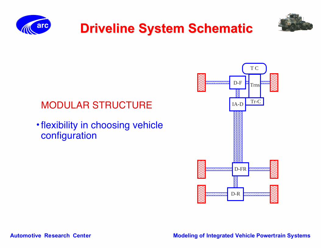
DrivelineDriveline System Schematic System Schematic
AAAAAAAAAA
AAAAAAAA
AAAAAAAA
AAAAAAAA
AAAAAAAA
AA
AA
AAA
AAA
AAA
AAA
Trns
Tr-C
D-F
AAAAAAAAAAAAAAAAAA
D-FR
D-R
IA-D
T C
MODULAR STRUCTURE
¥ flexibility in choosing vehicleconfiguration

10
arc
Automotive Research Center Modeling of Integrated Vehicle Powertrain Systems
Torque ConverterTorque Converter
¥3 element torqueconverter (pump,turbine & stator)
¥Static or dynamicmodel?
TURBINE
STATOR CONCAVE SIDE
STATOR CONVEX SIDE
PUMP DRIVE HUB
IMPELLER
IMPELLER ROTATION DIRECTION
(J.C. WHITE/FORD MOTOR CO.)

11
arc
Automotive Research Center Modeling of Integrated Vehicle Powertrain Systems
Torque Converter ModelTorque Converter Model
¥ Static Model Methodology (e.g., Salaani and Heydinger,1998)
¥ Implementation- 20SIM -> C code -> Matlab/Simulink
- Direct block diagram entry to Matlab/Simulink
Engine Speed
Turbine Speed Speed Ratio
Engine Speed
Capacity Factor
2
Torque Ratio
Capacity Factor
TurbineTorque(to trans.)
PumpTorque(to engine)

12
arc
Automotive Research Center Modeling of Integrated Vehicle Powertrain Systems
Automatic TransmissionAutomatic Transmission
¥Modeling Strategies- Input-output model based on experimental data- Physical component-level model
INPUT TORQUE
OUTPUT SHAFT SPEED
TURBINE SPEED
TORQUE TO DIFFERENTIAL
TRANSMISSION
TURBINE SPEED TORQUE TO TRANS.
TORQUE CONVERTER
INPUT TORQUE INPUT SHAFT SPEED
DIFFERENTIAL

13
arc
Automotive Research Center Modeling of Integrated Vehicle Powertrain Systems
Input-Output Transmission ModelInput-Output Transmission Model
¥ Based on experimental measurement of input and outputeffective inertias, stiffnesses, and damping
¥ Implemented as discrete components (e.g. Bond Graph)- 20SIM -> C-MEX files -> Matlab/Simulink
¥ Incorporates losses- Gear inefficiency
- Fluid pumping
INPUT INERTIA
OUTPUT INERTIA
GEAR REDUCTION

14
arc
Automotive Research Center Modeling of Integrated Vehicle Powertrain Systems
Input-Output Transmission ModelInput-Output Transmission Model
Empirical blending functions are used for shifting.
Speed Ratio
Torque Ratio
Time
Shift Duration

15
arc
Automotive Research Center Modeling of Integrated Vehicle Powertrain Systems
Alternative Transmission ModelAlternative Transmission Model
¥ Physical-Based Model (Choand Hedrick, 1989)
¥ Model considers inertias ofgears and compliances ofshafts
¥ Clutches engage/disengage during shiftevent- Torque phase
- Speed phase
¥ Model can switch betweenbond graphs for differentphases
TO 1-2 BAND
TO FINAL DRIVETO FIRST CLUTCH
TO SECOND CLUTCH
TO SECOND CLUTCH
TO 1-2 BAND

16
arc
Automotive Research Center Modeling of Integrated Vehicle Powertrain Systems
Shift LogicShift Logic
¥ Decision to shift based on- Transmission output shaft
speed
- Throttle position
¥ Implementation- C-MEX function
È Accepts inputs fromtransmission and driver
È Outputs gear number, torquemultiplication and speedreduction ratios Output Shaft Speed [rad/s]
ThrottlePosition[0-1]
1 2 3 4

17
arc
Automotive Research Center Modeling of Integrated Vehicle Powertrain Systems
Differential/Driveshaft ModelsDifferential/Driveshaft Models
¥ Differentials- Bond graph representations
È Conventional bevel-gear
È Worm-gear
¥ Propshafts and Driveshafts- Compliance, inertia, damping
- Axle cooler churning losses
¥ Implementation- 20SIM -> C-MEX files
WHEEL
WHEEL
DIFFERENTIALAUTOMATIC TRANS.

18
arc
Automotive Research Center Modeling of Integrated Vehicle Powertrain Systems
Vehicle SpecificationsVehicle Specifications
¥ V8 DI Diesel
¥ Turbocharged, Intercooled
¥ Rated Power: 210 HP@2400 rpm
¥ GVWR: 7950 Kg
¥ 4 Speed Automatic Transmission
¥ Rear Wheel Drive - 4x2
Vehicle/DrivelineEngine
NAVISTAR 4700 Series

19
arc
Automotive Research Center Modeling of Integrated Vehicle Powertrain Systems
Validation and Parametric StudyValidation and Parametric Study
¥Vehicle launch performance validation- Ò0-60 mphÓ full throttle acceleration from idle- Engine and vehicle speed compared to experimental data
¥Torque converter stall test validation- Compare torque converter stall speed with test data
¥Shift quality parametric study- Shift duration nominally 0.8 seconds- Vary duration +/- 0.4 seconds- Compare vehicle forward jerk

20
arc
Automotive Research Center Modeling of Integrated Vehicle Powertrain Systems
0 5 10 15 20 25 30 350
500
1000
1500
2000
2500
3000
0 5 10 15 20 25 30 350
10
20
30
40
50
60
Model Validation (0-60 MPH)Model Validation (0-60 MPH)
ENG
INE
SPE
ED [
RPM
]
TIME [SEC]
TestVESIM
VEH
ICLE
SPE
ED [
MPH
]
TestVESIM
1st 2nd 3rd 4th Gear

21
arc
Automotive Research Center Modeling of Integrated Vehicle Powertrain Systems
0 1 2 3 4 5 60
500
1000
1500
2000
2500
3000
3500
4000
Torque Converter Stall TestTorque Converter Stall Test
TIME [SEC]
ENG
. S
PEED
[RP
M]
TestVESIM

23
arc
Automotive Research Center Modeling of Integrated Vehicle Powertrain Systems
Shift Quality - Vehicle JerkShift Quality - Vehicle Jerk
0 0.1 0.2 0.3 0.4 0.5 0.6 0.7 0.8-8
-6
-4
-2
0
2
4
6
8
NORMALIZED TIME [SEC]
FORW
ARD
JER
K [
M/
S^3
]
¥ Consider trade-offbetween ridequality and- Acceleration
- Clutch wear
0.4 sec shift0.8 sec shift1.2 sec shift

24
arc
Automotive Research Center Modeling of Integrated Vehicle Powertrain Systems
SummarySummary
¥An inventory of models for different powertraincomponents has been implemented
¥Driveline models have been integrated withengine and vehicle (VESIM)
¥Models have been partially validated with testdata
¥Potential utility of simulation tool has beenexplored through example design studies

25
arc
Automotive Research Center Modeling of Integrated Vehicle Powertrain Systems
ConclusionsConclusions
¥Vehicle/engine integration of varying fidelity ispossible
¥Engine/vehicle interactions appear to be importantto vehicle mobility design and evaluation
¥Additional work on driveline models is necessary

26
arc
Automotive Research Center Modeling of Integrated Vehicle Powertrain Systems
Future WorkFuture Work
¥Extend usefulness of VESIM as predictive designtool by expanding component model inventory
¥Continue data collection effort for validation