propellant perforation for a depleted carbonate subsea … · propellant perforation for a depleted...
TRANSCRIPT

1
Presenter: Nicholas Hendry, HPHT Completion EngineerShell U.K
Propellant Perforation for a Depleted Carbonate Subsea Gas Well – Malampaya
SPE ICoTA 20th European Well Intervention Conference

Co-Authors & Acknowledgement
Jim Gilliat, Baker Hughes
Mark Brinsden, Shell
Neil Harvey, Shell
Vikas Bhushan, Shell
Milind Bhagwat, Shell
Michael Tan, Shell

Agenda
Malampaya Asset - Overview
Malampaya Phase 2 Project – Overview
Well Performance: Expected vs. Actual
STIMGUN Selection
Process Safety Due Diligence
—PULSFRAC Modeling
Conclusions & Project Learning's

Overview
Malampaya Asset
1.0

Malampaya Asset
Malampaya Deep water Gas to Power Project
Reservoir: Deep water, gas carbonate
Wells: 7 subsea wells in 820m water
Flowlines: 2 x 28 km Corrosion Resistant Alloy flowlines
Platform: Concrete gravity base platform in 43m water, offshore dehydration,continuous Methanol (MeOH) injection, remote control from onshoregas plant
Pipeline: 504 km 24” gas export pipeline
Gas plant: Onshore treatment plant uses amine process to sweeten and molesieves to dehydrate the landed sour gas. Currently operating in drygas mode (i.e. low H2S)
Customers: Gas sold to 3 power stations (design 2700 MW)
Capacity: 528 MMscf/d of gas32,800 bbl/d of condensate

Subsea to Shallow Water Platform to onshore…
6

MALAMPAYA RESERVOIR CHARACTERISTICS
� Carbonate – vugs, karsts, fractures – Highly Heterogeneous
� Average Porosity 18%
� Average Matrix Permeability 250-350 mD/ Effective Permeability 2 D
� Reservoir Temperature 115 deg C

8
Reservoir Pressure Decline
Reservoir Pressure depleted by a third in 10 years
Biggest subsurface challenge – drilling in a highly fractured depleted carbonate
2700
3200
3700
4200
4700
Aug-01 Aug-02 Aug-03 Aug-04 Aug-05 Aug-06 Aug-07 Aug-08 Aug-09 Aug-10 Aug-11 Aug-12 Aug-13 Aug-14
Pre
ssu
re (
psi
)
Reservoir Pressure(closed -in BHP @centroid -3188.9 mtvdss and z-2phase corrected)
MA5 BHP
MA8 BHP
MA9 BHP
MA7 BHP
Pvirgin
2/3 Pvirgin
PDHG Pressure Readings from
three development
wells

Status Update
Malampaya Phase 2 Overview
2.0

Completion Overview
Max. Deviation 49.1o
Design Life 20 years
Cased & Perforated
Zero intervention philosophy
Through tubing perforation
—2” CT N2 for unloading if required
Stimulation: STIMGUN
Tubing: 7” X 9-5/8” X 7”
—TR-SCSSSV 7”
Surveillance: Permanent Downhole Pressure Gauge (PDHG)

Completion schematic
7” 29# SM13Cr S110 VAM TOP HC Tubing
7” TRSSSV
9 5/8” 53.5# SM13Cr S110 VAM 21 Tubing
7” 29# SM13Cr S110 VAM TOP HC Tubing
7” PDHG Mandrel
9 5/8” Hydrostatic Set Production Packer
AOF nipple
Guide bottom

Gun Selection
200 m of perforation length per well
7” Liner Cased & Perforated Completion
3-3/8” OD STIMGUN was shortlisted
—Min ID of Tubing hanger at subsea tree was 5.12”
Standard 6 SPF shot density, 60 deg phasing
Deep Penetrating HMX charges

Overview
Well Performance: Expected vs Actual
3.0
LWD Reservoir Quality
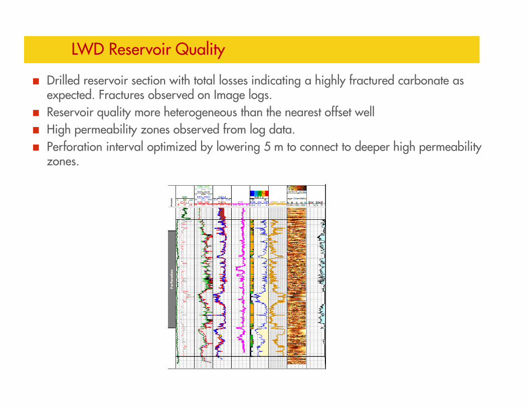
Drilled reservoir section with total losses indicating a highly fractured carbonate as expected. Fractures observed on Image logs.
Reservoir quality more heterogeneous than the nearest offset well
High permeability zones observed from log data.
Perforation interval optimized by lowering 5 m to connect to deeper high permeability zones.

Well Testing Overview
Estimated 150 MMscf/day demonstrated
Clean up criteria achieved
Final Salinity 235 ppm and 0% BSW solids
~200 ft flare – Weather favourable
Dual Separator mode on the rig flowed to 120 MMscf/day (measured) -
STABLE flow
Ensco 8504 DP Rig Well Testing ~ 200 ft flare

Expected IPR vs. Actual Flow Performance
Benefit of near well bore stimulation & thick high permeability reservoir sections
P Res

STIMGUN Selection
4.0
Why did we need some form of Stimulation?
Reservoir Pressure depleted by 1/3rd from virgin pressure
Huge drilling & cementing losses expected
Presence of Karsts
Could expect thick damage zone around the wellbore that could go beyond depth of penetration offered by conventional perforations
Large uncertainty in permeability prognosis – Carbonates
Inefficient clean-up due to insufficient delta P or deeper invasion in high permeability zones leading to a turbulent drainage pattern into the wellbore
Zero Intervention Philosophy - Well Completion Design
—No interventions preferred. Stimulation(acid jobs) in retrospect if wells do not flow at expected capacity
Insurance against non-deliverability of wells due to formation damage
—Contributes to 40% of the Philippines Luzon Island’s power grid

What we needed?
Some near wellbore stimulation to bypass any potential damage zone
Not expecting new fracture generation as the reservoir was already
fractured
Propellant loading could be kept modest to achieve this objective

Acid Jobs vs. Propellant Assisted Perforation
Complete stimulation of the reservoir section is very difficult to achieve
using acid diversion techniques in a karstic environment due to the large
variability in the permeability
Technology Solution: Propellant-assisted perforating technique - Stimulation
with Perforation – STIMGUN
Propellant-assisted perforating was considered as it achieves effective
stimulation diversion equally across the entire perforated interval
Additionally, its usage eliminates the need for conventional, separate acid
stimulation saving rig time and costs while reducing HS&E risks.

PULSFRAC Modeling
PROCESS SAFETY DUE DILLIGENCE
5.0

22
Biggest Uncertainty
Quality of cement behind the 7” liner
Model the Worst Case Scenario: Assume complete loss of cement to the
depleted reservoir

PULSFRAC Modeling Results
23
StimGun is loaded at 30% coverage, burn is complete.
There is no fracturing but a surge effect has reduced the initial skin from +4.2 to zero.

24
PULSFRAC Modeling Results
Lack of reservoir pressure
means no fracturing.
There is no “push back”
from the formation,
therefore pressure does
not build up in the
wellbore.
30% coverage does not
provide enough energy
to promote fracturing.
This is a result of the
formation pressure
allowing the gas to feed
into the reservoir rather
than building up in the
wellbore.

25
Conclusions
Stimulation was deemed necessary for Malampaya wells given the depleted reservoir
and total losses scenario expected
STIMGUN was selected based on optimization of rig time, ineffectiveness of acid jobs
in a karstified, fractured carbonate and Process Safety considerations
2” CT collapse risk mitigation achieved by:-
� Moderate propellant loading to 30%
� Overbalance Perforation preferred to make system stiffer
� Seawater + MEG mixture inside and outside coil(for hydrate prevention)
� N2 lift contingency as well unloading plan if required
200 m Perforation guns perforated successfully with 30% propellant loading
Better inflow performance than expected: Benefit of near well bore stimulation & thick
high permeability reservoir sections

26
Malampaya Perforation Design - Project Learnings
Always work very closely with vendor and do not assume
Get Principal Technical Expert/Subject Matter Expert steer early into the Project to
ensure all risks are completely assessed
Static conditions modeling is not adequate – CIRCA, Cerebrus models
Detailed dynamic analysis of actual Bottom Hole Assembly (Perforation) should be
modeled including the accurate spacer lengths, blank section to assess the impact of
pressure surges/dynamic UB
PULSFRAC Modeling: Always update the models after drilling the reservoir section
with actual LWD based reservoir quality info to see how the dynamic perforation
wave impacts the bottom hole assembly and completion components and how much
energy gets absorbed by the formation

27
Malampaya Perforation Design - Project Learnings
Check for differential pressures across packer and liner hanger components
12.8m spacer sub chosen for Malampaya Phase 2 wells to ensure top shot below the
rotary for personnel safety while RIH
Ensure proper Management Of Change is followed and take vendors along in all the
discussions
Time consuming finite element modeling work in PULSFRAC
As a single operated asset in the Philippines, the operator Shell effectively leveraged
on its global resources & expertise, e.g. global technology centers in India, Europe
and US, and operations teams in the region. A degree of collaborative virtual
working is essential for success in today’s world.
