proofer oven with touch screen controls (tsc)
TRANSCRIPT

MAINTENANCE MANUAL
PROOFER OVEN WITH TOUCH SCREEN CONTROLS (TSC)
Models:TSC-6/18M TSC-3/9M
IMPORTANT INFORMATION, READ BEFORE USE. PLEASE SAVE THESE INSTRUCTIONS.
This manual is Copyright © 2013 Duke Manufacturing Company. All rights reserved. Reproduction without written permission is prohibited. Duke is a registered
trademark of the Duke Manufacturing Company.
Duke Manufacturing Company2305 N. Broadway
St. Louis, MO 63102Phone: 314-231-1130
Toll Free: 1-800-735-3853Fax: 314-231-5074www.dukemfg.com
P/N 120086REV E 6/8/2017
MAINTENANCE BY QUALIFIED, TRAINED PERSONNEL ONLY

Maintenance Manual for DUKE TSC Proofer Oven with Touch Screen Controls
2
3
Maintenance Manual for DUKE TSC Proofer Oven with Touch Screen Controls
TABLE OF CONTENTSIMPORTANT SAFETY INSTRUCTIONS ............................................................................4OVEN/PROOFER START-UP .............................................................................................6PROGRAMMING CONTROLS ............................................................................................7CARE AND CLEANING .......................................................................................................10DOOR ADJUSTMENTS AND GASKET MAINTENANCE ...................................................14 TROUBLESHOOTING .......................................................................................................21PARTS LIST AND ILLUSTRATIONS ...................................................................................22WIRING DIAGRAM .............................................................................................................25

Maintenance Manual for DUKE TSC Proofer Oven with Touch Screen Controls
4
IMPORTANT SAFETY INSTRUCTIONS
Throughout this manual, you will find the following safety words and symbols that signify important safety issues with regards to operating or maintaining the equipment.
WARNING Indicates a hazardous situation which, if not avoided, could result in death or serious injury.
CAUTION Indicates a hazardous situation which, if not avoided, could result in minor or moderate injury.
CAUTION Indicates Important Information
Indicates electrical shock hazard which, if not avoided, could result in death or serious injury and/or equipment damage.
Indicates hot surface which, if not avoided, could result in minor or moderate injury. Specifically, risk of burn from heating elements.
Indicates rotating fan blade hazard which, if not avoided, could result in minor or moderate injury.
Indicates hot surface which, if not avoided, could result in minor or moderate injury.
In addition to the warnings and cautions in this manual, use the following guidelines for safe operation of the unit.
• Read all instructions before using equipment.
• Do not attempt to defeat the grounded connector.
• Install or locate the equipment only for its intended use as described in this manual.
• Do not use corrosive chemicals, water jet equipment, or other pressurized liquid spraying equipment to clean this unit.
• This equipment should be serviced by qualified personnel only. Contact the nearest Duke authorized service facility for adjustment or repair.
• Do not block any openings on the unit.
• A minimum clearance of 6″ (152.4 mm) from the top of the unit to the ceiling must be provided.
• Secure unit to a wall with brackets provided to prevent tipping.
• Unit may start operation with inadvertent contact with touch screen display or from other extraneous sources. Turn off all poles mains disconnects should abnormal or unwanted operation occur.

5
Maintenance Manual for DUKE TSC Proofer Oven with Touch Screen Controls
• Install the Restraining Device Kit to prevent damage to main supply connections.
• This appliance can be used by children aged from 8 years and above and persons with reduced physical, sensory or mental capabilities or lack of experience and knowledge if they have been given supervision or instruction concerning use of the appliance in a safe way and understand the hazards involved. Children shall not play with the appliance. Cleaning and user maintenance shall not be made by children without supervision.
• Turn off external mains supply disconnect and allow unit to cool down before servicing or performing maintenance.
• The procedures in this manual may include the use of chemical products. You must read the Material Safety Data Sheets before using any of these products.
• Properly rated all poles mains protection and earthing compliance with local electric codes are required for safe operation of this unit.
• Water supply connections to the unit must comply with local plumbing code and/or standards.
• Disposal of the unit must be in accordance with local environmental codes and/or any other applicable codes.
• SAVE THESE INSTRUCTIONS
Technical Description and Application Notes for TSC Proofer Oven Backflow Preventer Assembly
This equipment is intended to be connected to apotable water supply system under pressure and is to be installed with adequate backflow protection
to comply with all applicable federal, state, andlocal codes.
Water supply pressure for proper operation shall be: Minimum 40 PSIG(275 KPa) Maximum 65 PSIG(448 KPa)
measured at water line inlet to the equipment.
If so equipped, regular maintenance is required toreplace the water filter cartridge at least once peryear, and to clean the inlet water screen at leastonce per year. Consult state/local codes for any
additional requirements.
INSTALLATION OF WATER FILTER
Install new filter by removing sanitary cap from topof cartridge, insure two black O-rings are in place,
then lift up into filter head and rotate cartridge1/4 turn counter clockwise until it comes to a complete
stop. Flush 2 gallons (7.5 Liters) of water through thenew filter before using proofer to purge air from filter.Remove hose from bottom of proofer by loosening
the compression nut at the disconnect fittingand pull hose out. Place hose over container and
turn on water. It will take a minute for the filterto fill before water flows out of hose into container.
Once filter is flushed with 2 gallons (7.5 Liters) of water,turn off water supply again, insert hose into water line
disconnect, tighten compression nut and turnwater supply on again. Check for leaks at
connection fittings.
Patent(s) Pending
5127
76 D
Check with your local authority having jurisdiction regarding approvals for connecting the Duke TSC Proofer Oven to a potable water supply before making any plumbing connections. Plumbing code requirements vary, but Duke has a kit (P/N 600187) available or installed as a factory option, for backflow prevention to protect water supply systems by preventing the reverse flow of non-potable water into the potable domestic water system. The device consists of two independently acting check valves, internally force-loaded to a normally closed position and designed/constructed to operate under intermittent or continuous pressure conditions.
The two main components of the Duke backflow preventer system are:
• Dual Check Valve type backflow preventer that conforms to ANSI/ASSE standard #1024 and is CSA standard B64.6 certified.
• Inlet water strainer equipped with 100-mesh screen and installed up stream of the backflow preventer. The screen is conveniently located on the rear panel of the proofer, below the backflow preventer, for easy access during cleaning/replacement.
Maintenance Manual for DUKE TSC Proofer Oven with Touch Screen Controls
6
WARNING ELECTRICAL SHOCK HAZARD.
DISCONNECT POWER TO SERVICE UNIT.
TASKS MUST BE PERFORMED BY A QUALIFIED SERVICE TECHNICIAN OR ELECTRICIAN.
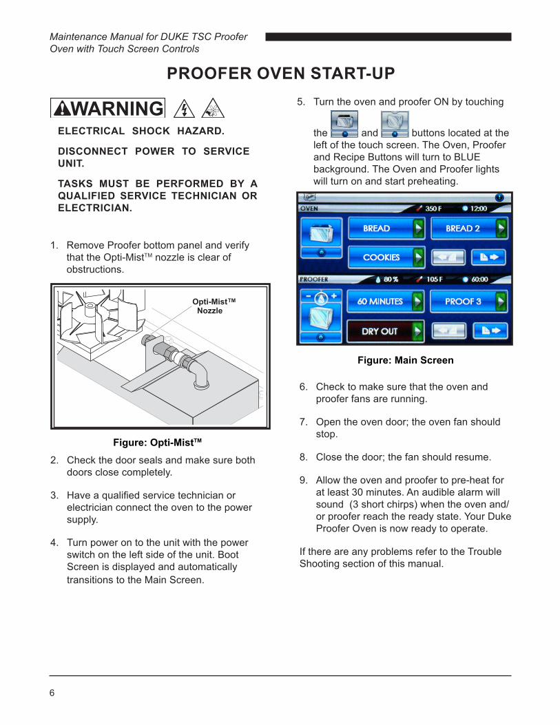
1. Remove Proofer bottom panel and verify that the Opti-MistTM nozzle is clear of obstructions.
TM
6. Check to make sure that the oven and proofer fans are running.
7. Open the oven door; the oven fan should stop.
8. Close the door; the fan should resume.
9. Allow the oven and proofer to pre-heat for at least 30 minutes. An audible alarm will sound (3 short chirps) when the oven and/or proofer reach the ready state. Your Duke Proofer Oven is now ready to operate.
If there are any problems refer to the Trouble Shooting section of this manual.
Figure: Main Screen
5. Turn the oven and proofer ON by touching
the and buttons located at the left of the touch screen. The Oven, Proofer and Recipe Buttons will turn to BLUE background. The Oven and Proofer lights will turn on and start preheating.
PROOFER OVEN START-UP
Figure: Opti-MistTM
2. Check the door seals and make sure both doors close completely.
3. Have a qualified service technician or electrician connect the oven to the power supply.
4. Turn power on to the unit with the power switch on the left side of the unit. Boot Screen is displayed and automatically transitions to the Main Screen.

7
Maintenance Manual for DUKE TSC Proofer Oven with Touch Screen Controls
PROGRAMMING CONTROLS
RECIPE EDIT PROGRAMMING INSTRUCTIONS
1. Touch the button and then enter pin code 5 6 7 8 and Touch the button when prompted.
2. Touch the button for the recipe you want to edit (i.e. BREAD ).
NOTE: The 6 oven recipes are listed in the top 3 rows and the 6 proofer recipes are listed in the bottom 3 rows.
3. To edit Time, Temperature or Humidity (Proofer Only), touch the or button adjacent to the field you want to change. Touch the button to save the changes.
NOTE: You must touch the button in each field to save the changes you made.
FIGURE: Recipe Edit Selection Screen
Figure: Recipe Edit Screen
Figure: Main Tool Bar
Figure: Special Functions Screen
To access the SPECIAL FUNCTIONS, touch button on the Main Tool Bar.

Maintenance Manual for DUKE TSC Proofer Oven with Touch Screen Controls
8
5. Touch the button to save the changes and return to the RECIPE EDIT Screen. If no changes are required touch the button to go back to the RECIPE EDIT Screen.
NOTE: You must touch the button to save the changes you made.
6. When complete, touch the button to go back to the previous screen. Press multiple times to return to the main screen.
4. To edit the recipe name, touch the button for the EDIT RECIPE NAME screen.
NOTE: Typing will add letters/characters to the end of the text.
PRESS:
• TO TOGGLE THE KEYBOARD BETWEEN THE UPPER/LOWER CASE CHARACTER SET.
• , AND FOR THE NUMBER AND SYMBOL KEYBOARDS.
• TO SPACE
• TO CLEAR ALL TEXT
• TO DELETE/BACKSPACE
Figure: Edit Recipe Name Screen

9
Maintenance Manual for DUKE TSC Proofer Oven with Touch Screen Controls
FILES (FILE MANAGEMENT)
1. Touch the button and then enter pin code 3 4 5 6 and Touch the button when prompted.
2. Insert USB drive with the file, until seated, into the USB Host Device.
3. Select file operation from list and follow instruction on the display screen.
Figure: Inserting USB Drive Into USB Host Device
Figure: File Management Screen
CONFIG (CONFIGURATION S)
1. Touch the button and then enter pin code 2 3 4 5 and Touch the button when prompted.
2. Touch the button for the setting you want to edit.
• DATE/TIME – Touching will display DATE/TIME edit screen. Touch the or button adjacent to the field you want to change. Touch the button to save the changes.
• LANGUAGE – Touching will display a list of included languages. Touch the preferred language button to select.
• C/F SELECT – Touching will toggle between CENTIGRADE MODE ENABLED and FAHRENHEIT MODE ENABLED.
• DEFAULT RECIPE – Touching will reload factory defaults.
• SYSTEM STATUS – Touching will display Proofer Oven status.
Figure: Configurations Screen

Maintenance Manual for DUKE TSC Proofer Oven with Touch Screen Controls
10
CARE AND CLEANINGWEEKLY CLEANING INSTRUCTIONS
1. Clean Proofer. Turn the proofer off and allow elements to cool. Remove the bottom panel (remove screw). Remove excess water by wiping it up with a dry cloth. Clean bottom panel to remove any mineral deposits and debris with hot soapy water and follow with clean damp cloth.
2. Clean Opti-Mist proofer spray Nozzle.
A. Remove nozzle assembly by depressing latch on quick-connect fitting and pull nozzle out toward fan blade.
B. Soak nozzle in plain white vinegar for 4-8 hours to dissolve mineral deposits. Wipe residue from nozzle and rinse in clean water.
C. Do not insert objects into nozzle outlet as this can change the water spray performance.
D. Replace nozzle assembly if mineral deposits from hard water cannot be removed.
E. Reinstall nozzle by inserting into quick-connect fitting until fully seated.
Figure: Opti-MistTM Quick Connect Nozzle
TM
TM
WARNING PROOFER OVEN INTERIOR AND RACKS ARE VERY HOT AND COOL SLOWLY. ALLOW TO COOL BEFORE HANDLING.
CAUTION ELECTRICAL SHOCK HAZARD.DO NOT WASH WITH WATER JET OR HOSE.
CAUTION RISK OF CUT FROM ROTATING FAN BLADE.
DISCONNECT POWER TO SERVICE.
CAUTION RISK OF BURN FROM HEATING ELEMENTS.
DISCONNECT POWER AND ALLOW TO COOL TO SERVICE.
CAUTIONDO NOT USE OVEN CLEANERS, CAUSTIC CLEANERS, DEGREASERS, ACIDS, AMMONIA PRODUCTS, ABRASIVE CLEANERS, STEEL WOOL, OR ABRASIVE PADS CONTAINING IRON. THESE CAN DAMAGE THE STAINLESS STEEL, DOOR GASKETS AND PLASTIC SURFACES.

11
Maintenance Manual for DUKE TSC Proofer Oven with Touch Screen Controls
3. The Cool-Touch door has two window panes. The inner window can be easily separated from the outer window for cleaning. This is achieved by unlatching two clips and rotating the inner window on its hinges. After cleaning, the inner window frame is easily clipped to the outer window by squeezing the two windows together. For additional detail refer to "Cool-Touch Door Information" section of this manual.
4. Inspect oven & proofer door gaskets for cuts, tears or any other damage. Refer to the section on "Door Adjustments and Gasket Maintenance" for directions.
Monthly Care and Cleaning Instructions
1. Check door handle screws for tightness.
2. Check the door gasket seal on the Oven and Proofer for leaks. Refer to the section on "Door Adjustments and Gasket Maintenance" for directions.
CAUTIONHEAVY WATER FILTER CARTRIDGE CAN PINCH HANDS.
USE CARE WHEN REMOVING.
Annual Cleaning Instructions
CAUTIONREPLACE FILTER CARTRIDGE ONLY WITH DUKE FACTORY AUTHORIZED REPLACEMENT PARTS TO ENSURE PROPER OPERATION.
CAUTIONWATER FILTER CARTRIDGE IS UNDER PRESSURE, SLOWLY REMOVE CARTRIDGE TO RELEASE PRESSURE.
1. Replace water filter cartridge & clean inlet strainer.
A. Turn off water supply to oven.
B. Disconnect Wall Brackets if installed. See Installation of wall brackets section of manual.
C. Turn off power to Proofer Oven.
Maintenance Manual for DUKE TSC Proofer Oven with Touch Screen Controls
12
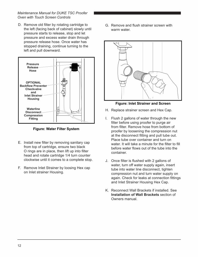
D. Remove old filter by rotating cartridge to the left (facing back of cabinet) slowly until pressure starts to release, stop and let pressure and excess water drain through pressure release hose. Once water has stopped draining, continue turning to the left and pull downward.
H. Replace strainer screen and Hex Cap.
I. Flush 2 gallons of water through the new filter before using proofer to purge air from filter. Remove hose from bottom of proofer by loosening the compression nut at the disconnect fitting and pull tube out. Place tube over container and turn on water. It will take a minute for the filter to fill before water flows out of the tube into the container.
J. Once filter is flushed with 2 gallons of water, turn off water supply again, insert tube into water line disconnect, tighten compression nut and turn water supply on again. Check for leaks at connection fittings and Inlet Strainer Housing Hex Cap.
K. Reconnect Wall Brackets if installed. See Installation of Wall Brackets section of Owners manual.
Figure: Inlet Strainer and Screen
Figure: Water Filter System
E. Install new filter by removing sanitary cap from top of cartridge, ensure two black O rings are in place, then lift up into filter head and rotate cartridge 1/4 turn counter clockwise until it comes to a complete stop.
F. Remove Inlet Strainer by loosing Hex cap on Inlet strainer Housing.
G. Remove and flush strainer screen with warm water.

13
Maintenance Manual for DUKE TSC Proofer Oven with Touch Screen Controls
L. Turn on power to Proofer Oven.
Caution: Replace filter cartridge only with Duke factory-authorized replacement parts to ensure proper operation. See Parts List
section of manual for part number.
Figure: Water Filter (Flushing 2 gallons of water)
Water Line Disconnect
Fitting
Proofer Oven With Optional Backflow
Preventer
Proofer Oven Without Optional
Backflow Preventer
Inlet Water Connection
Point
Figure: Opti-MistTM Nozzle Filter
2. Clean Opti-MistTM proofer nozzle screen.
A. Remove nozzle assembly by depressing latch on quick-connect fitting and pull nozzle out toward fan blade.
B. Use 3/4" and 5/8" wrenches to remove nozzle from body.
C. Unscrew filter screen using fingers.
D. Use 5/32 allen wrench to remove diffuser retainer, diffuser and centering sleeve.
E. Soak all parts in plain white vinegar for 4-8 hours to dissolve mineral deposits. Wipe residue from nozzle and rinse in clean water.
F. Do not insert objects into nozzle outlet as this can change the water spray performance.
NOTE: Ensure proper orientation of the Diffuser Retainer.
H. Replace nozzle assembly if mineral deposits from hard water cannot be removed.
I. Reinstall nozzle by inserting into quick-connect fitting until fully seated.
G. Reassemble nozzle.

Maintenance Manual for DUKE TSC Proofer Oven with Touch Screen Controls
14
DOOR ADJUSTMENTS & GASKET MAINTENANCE
WARNING
REVERSING OVEN DOOR SWING DIRECTION
1. Remove cover from hinges to expose the screws that hold the hinge to the front of the oven.
2. Remove the hinge screws and door from the oven.
3. Remove the door handle screws, flip the door handle over and replace it on the door.
4. Remove the six screws on the front of the oven to expose the hinge screw holes for the other swing direction.
5. Use the six screws to fill the unused hinge screw holes on the front of the oven.
6. Remove the latch strike plate from the front of the oven and move it to the other side. Use the screws from the other side to fill the screw holes that are no longer used.
7. Position the door on the front of the oven and tighten the hinge screws. Make sure the door is level with the oven body before the screws are tightened permanently.
8. Adjust the door gasket seal.
Figure: Illustration – Reversing Oven Door Direction
15
Maintenance Manual for DUKE TSC Proofer Oven with Touch Screen Controls
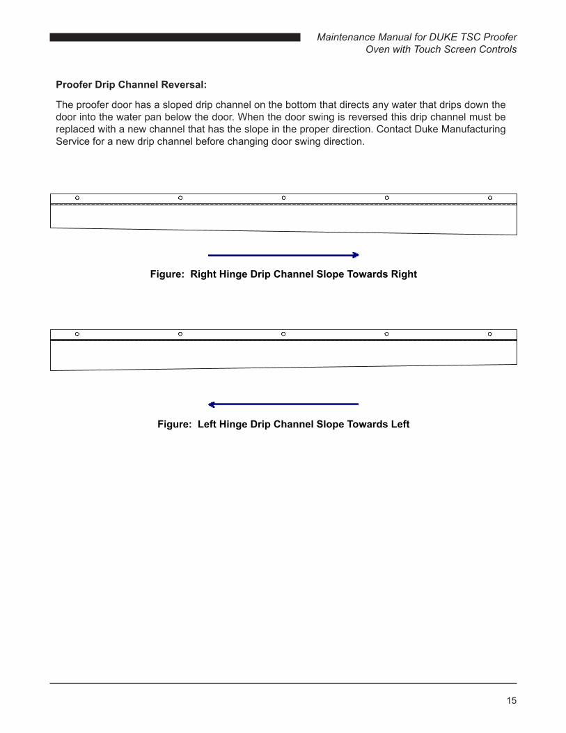
Proofer Drip Channel Reversal:
The proofer door has a sloped drip channel on the bottom that directs any water that drips down the door into the water pan below the door. When the door swing is reversed this drip channel must be replaced with a new channel that has the slope in the proper direction. Contact Duke Manufacturing Service for a new drip channel before changing door swing direction.
Figure: Right Hinge Drip Channel Slope Towards Right
Figure: Left Hinge Drip Channel Slope Towards Left

Maintenance Manual for DUKE TSC Proofer Oven with Touch Screen Controls
16
PROOFER DRIP CHANNEL REVERSAL:
1. Follow the directions for removing the door from the Reversing Oven Door section. When the door is off you can then replace the drip channel.
2. Remove the screws that hold the drip channel on and remove the drip channel. Use the same screws to fill the empty holes after the drip channel is off.
3. Locate the new drip channel on the other end of the door. Make sure that the slope is directed to the hinge side of the door.
4. Fasten the drip channel to the door with the self-tapping screws provided with the new drip channel.
5. Follow the directions from the Reversing Oven Door section for mounting the door.
DIRECTION OF SLOPE
NEW POSITION OF THE DRIP CHANNEL
Figure: Illustration – Reversing Proofer Door Direction

17
Maintenance Manual for DUKE TSC Proofer Oven with Touch Screen Controls
DOOR GASKET LEAK ADJUSTMENTS:
The doors should be checked for leaks every three months. The adjustment can be made by following the instructions below. If the door gasket is damaged or compressed permanently, it should be replaced. Call Duke Manufacturing Co. at 800-735-3853 to order a new gasket before making adjustments.
1. To check the adjustment, close the door with a currency bill between the gasket and front of the oven. Resistance should be felt when pulling the currency bill out with the door closed. Do this check in several places and readjust the door as necessary.
Figure: Gasket Check
2. With the door closed, remove the hinge covers with a screwdriver and loosen the six screws that hold the hinges to the door.
Figure: Removing Hinge Cover
Figure: Location of Hinge Screws

Maintenance Manual for DUKE TSC Proofer Oven with Touch Screen Controls
18
Figure: Hinge Side Adjustment
IMPORTANTBe careful not to compress the gasket too much, or it will not allow the door to be closed.
3. Adjust the door position by moving the door frame in or out to seal any gaps between the gasket and the oven. Adjustment is made using the screws on the handle and the hinges.
GasketGroove
DoorGasket
4. To check the adjustment, close the door with a currency bill between the gasket and front of the oven. Resistance should be felt when pulling the currency bill out with the door closed. Do this check in several places and readjust the door if necessary.
Figure: Gasket Check
GASKET REPLACEMENT:
1. Remove the old gasket by pulling it out of the groove in the door frame.
Figure: Door and Gasket
Figure: Handle Side Adjustment

19
Maintenance Manual for DUKE TSC Proofer Oven with Touch Screen Controls
COOL-TOUCH DOOR INFORMATION AND CLEANING INSTRUCTIONS
The Cool-Touch door has two window panes. The inner window can be easily separated from the outer window for cleaning. This is achieved by unlatching two clips and rotating the inner window on its hinges. After cleaning, the inner window frame is easily clipped to the outer window by squeezing the two windows together.
2. Clean the groove with a screwdriver or other flat-bladed tool to remove any dirt or gasket pieces.
Figure: Cleaning Gasket Groove
3. Press the new gasket into the groove. Make sure it is fully seated in the groove and flat against the door frame.
Figure: Properly Seated Gasket
4. Check the door adjustment to make sure there are not any leaks. Also, check that the new gasket is not compressed too much, making the door hard to close.
Figure: Cool-Touch Door inside view.1. To open the windows for cleaning, unlatch
the top clip.
Figure: Unlatch Top clip
Maintenance Manual for DUKE TSC Proofer Oven with Touch Screen Controls
20
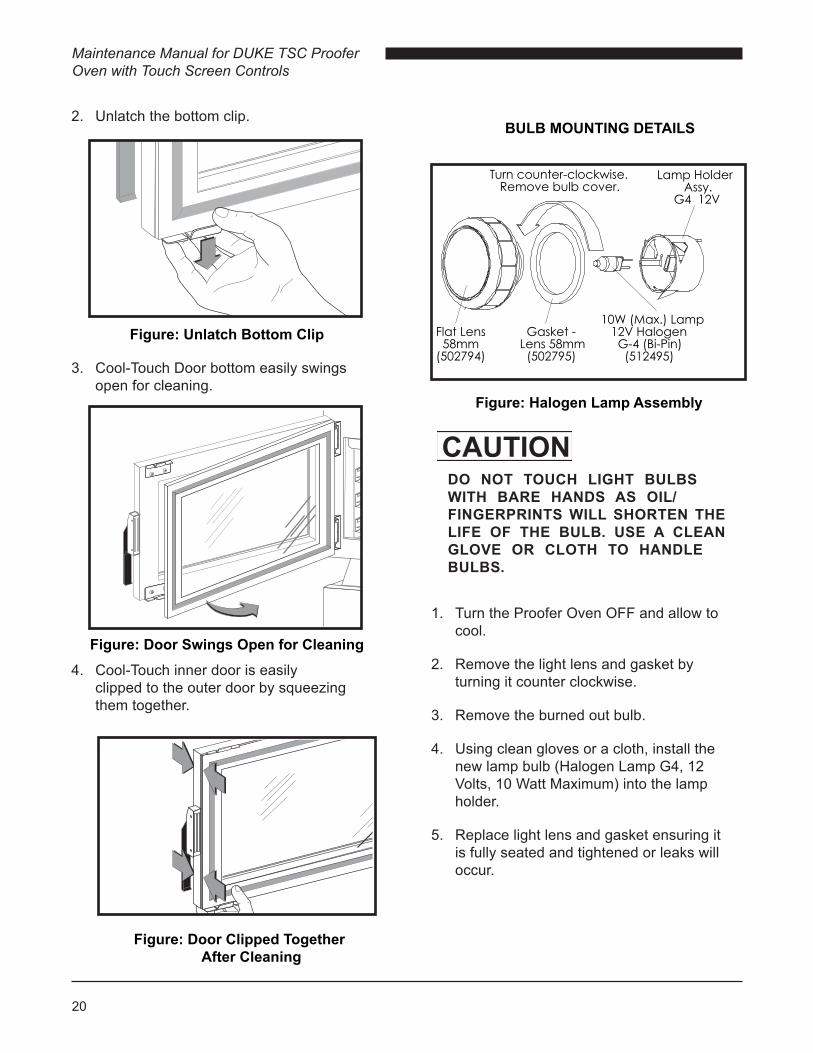
Figure: Halogen Lamp Assembly
Turn counter-clockwise. Remove bulb cover.
Lamp Holder Assy. G4 12V
Flat Lens 58mm(502794)
Gasket -Lens 58mm (502795)
10W (Max.) Lamp 12V Halogen G-4 (Bi-Pin) (512495)
2. Unlatch the bottom clip.
CAUTIONDO NOT TOUCH LIGHT BULBS WITH BARE HANDS AS OIL/FINGERPRINTS WILL SHORTEN THE LIFE OF THE BULB. USE A CLEAN GLOVE OR CLOTH TO HANDLE BULBS.
Figure: Door Clipped Together After Cleaning
Figure: Unlatch Bottom Clip
3. Cool-Touch Door bottom easily swings open for cleaning.
Figure: Door Swings Open for Cleaning4. Cool-Touch inner door is easily
clipped to the outer door by squeezing them together.
1. Turn the Proofer Oven OFF and allow to cool.
2. Remove the light lens and gasket by turning it counter clockwise.
3. Remove the burned out bulb.
4. Using clean gloves or a cloth, install the new lamp bulb (Halogen Lamp G4, 12 Volts, 10 Watt Maximum) into the lamp holder.
5. Replace light lens and gasket ensuring it is fully seated and tightened or leaks will occur.
BULB MOUNTING DETAILS
21
Maintenance Manual for DUKE TSC Proofer Oven with Touch Screen Controls
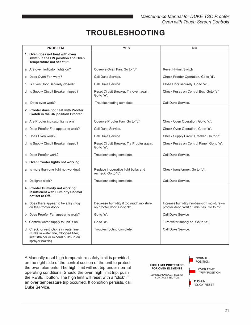
TROUBLESHOOTING
A Manually reset high temperature safety limit is provided on the right side of the control section of the unit to protect the oven elements. The high limit will not trip under normal operating conditions. Should the oven high limit trip, push the RESET button. The high limit will reset with a "click" if an over temperature trip occurred. If condition persists, call Duke Service.
PROBLEM YES NO
1. Oven does not heat with oven switch in the ON position and Oven Temperature not set at 0°.
a. Are oven indicator lights on? Observe Oven Fan. Go to “b”. Reset Hi-limit Switch
b. Does Oven Fan work? Call Duke Service. Check Proofer Operation. Go to “d”.
c. Is Oven Door Securely closed? Call Duke Service. Close Door securely. Go to “e”.
d. Is Supply Circuit Breaker tripped? Reset Circuit Breaker. Try oven again. Check Fuses on Control Box. Goto “e”. Go to “e”.
e. Does oven work? Troubleshooting complete. Call Duke Service.
2. Proofer does not heat with Proofer Switch in the ON position Proofer
a. Are Proofer indicator lights on? Observe Proofer Fan. Go to “b”. Check Oven Operation. Go to “c”.
b. Does Proofer Fan appear to work? Call Duke Service. Check Oven Operation. Go to “c”.
c. Does Oven work? Call Duke Service. Check Supply Circuit Breaker. Go to “d”.
d. Is Supply Circuit Breaker tripped? Reset Circuit Breaker. Try Proofer again. Check Fuses on Control Panel. Go to “e”. Go to “e”.
e. Does Proofer work? Troubleshooting complete. Call Duke Service.
3. Oven/Proofer lights not working.
a. Is more than one light not working? Replace inoperative light bulbs and Check transformer. Go to “b”. recheck. Go to “b”.
b. Do lights work? Troubleshooting complete. Call Duke Service.
4. Proofer Humidity not working/ insufficient with Humidity Control not set to Off.
a. Does there appear to be a light fog Decrease humidity if too much moisture Increase humidity if not enough moisture on on the Proofer door? on proofer door. Go to “b”. proofer door. Wait 15 minutes. Go to “b”.
b. Does Proofer Fan appear to work? Go to "c". Call Duke Service
c. Confirm water supply to unit is on. Go to "d". Turn water supply on. Go to "d".
d. Check for restrictions in water line. Troubleshooting complete. Call Duke Service. (Kinks in water line, Clogged filter, inlet strainer or mineral build-up on sprayer nozzle)

Maintenance Manual for DUKE TSC Proofer Oven with Touch Screen Controls
22
Duke TSC Proofer Oven Exploded View
PARTS LIST AND ILLUSTRATIONS
15
26
27
28
5
22
10
10
14
9
9
9
9
12
13
11
6
5
4
3
1
219
19
17
17
30
30
20
20
161632
31
2524
23
29
34
33
21
36
1837
38
35
7
39
23
Maintenance Manual for DUKE TSC Proofer Oven with Touch Screen Controls
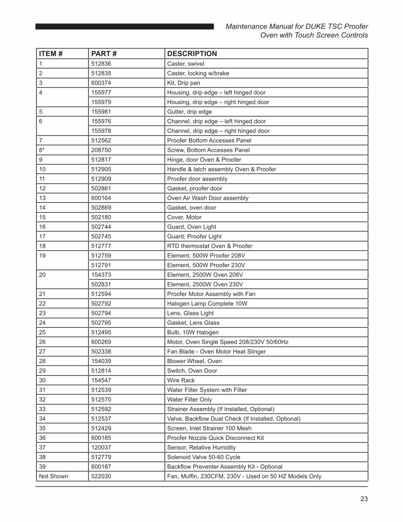
ITEM # PART # DESCRIPTION1 512836 Caster, swivel2 512835 Caster, locking w/brake3 600374 Kit, Drip pan4 155977 Housing, drip edge – left hinged door
155979 Housing, drip edge – right hinged door5 155981 Gutter, drip edge6 155976 Channel, drip edge – left hinged door
155978 Channel, drip edge – right hinged door7 512562 Proofer Bottom Accesses Panel8* 208750 Screw, Bottom Accesses Panel9 512817 Hinge, door Oven & Proofer10 512905 Handle & latch assembly Oven & Proofer11 512909 Proofer door assembly12 502861 Gasket, proofer door13 600164 Oven Air Wash Door assembly14 502869 Gasket, oven door15 502180 Cover, Motor16 502744 Guard, Oven Light17 502745 Guard, Proofer Light18 512777 RTD thermostat Oven & Proofer19 512759 Element, 500W Proofer 208V
512791 Element, 500W Proofer 230V20 154373 Element, 2500W Oven 208V
502831 Element, 2500W Oven 230V21 512594 Proofer Motor Assembly with Fan22 502792 Halogen Lamp Complete 10W23 502794 Lens, Glass Light24 502795 Gasket, Lens Glass25 512495 Bulb, 10W Halogen26 600269 Motor, Oven Single Speed 208/230V 50/60Hz27 502338 Fan Blade - Oven Motor Heat Slinger28 154039 Blower Wheel, Oven29 512814 Switch, Oven Door30 154547 Wire Rack31 512539 Water Filter System with Filter32 512570 Water Filter Only33 512592 Strainer Assembly (If Installed, Optional)34 512537 Valve, Backflow Dual Check (If Installed, Optional)35 512429 Screen, Inlet Strainer 100 Mesh36 600185 Proofer Nozzle Quick Disconnect Kit37 120037 Sensor, Relative Humidity38 512779 Solenoid Valve 50-60 Cycle39 600187 Backflow Preventer Assembly Kit - OptionalNot Shown 522030 Fan, Muffin, 230CFM, 230V - Used on 50 HZ Models Only

Maintenance Manual for DUKE TSC Proofer Oven with Touch Screen Controls
24
Control Panel Exploded View
ITEM # PART # DESCRIPTION40 120007 Panel Mount USB41 512568 Buzzer42 120011 Power Supply Board43 120030 TSC Input/Output Board44 600309 TSC Proofer Oven Controller Replacement Kit45 120026 Handle, Guard Control46 120061 Overlay, Touch Screen47 600373 Solid State Relay, 25A48 159092 Muffin Fan 230V49 512880 Breaker, Circuit, 3 Amp for Proofer Light Transformer50 512765 Thermostat, Hi-Limit51 120001 Terminal Block52 502937 Transformer 230V
502840 Transformer 208V53 156527 Power Switch
49
40
41
42
50
43
45
46
47
48
44
53
52
51

25
Maintenance Manual for DUKE TSC Proofer Oven with Touch Screen Controls
WIRING DIAGRAM
L1T1
SSR 4 +
L1T1
SSR 3 +
L1
L2
L3
N
+12V
urG
ND
CA
N-T
XC
AN
-RX
L1
PF Water Valve OV Light
PF Lt’s & Blower
IO MODULE
PCB
+12V
OV HeatPH Heat
OV ss sen
GND
Beeper
OV Door
+5V
GNDRH Input
GND
Vref
+ IN- IN
GND
Vref
+ IN- IN
GND
Vref
+ IN- IN
10A
ON
0 1 2 3
CONV. BLOWER
Beeper
+
N.C
.
N.O
.
Ov Door Sw. (Door Closed)
Com
PRIMARY
SECONDARY
PRIMARY
SECONDARY
12V
SAFETY LIMIT
1222
32
1121
31
HEAT
1 2 3 4
1 2 3 4
BLK “B”
BLK
IVS OPTION
BLK “C”
12345
12345
Pf RH
Pf Temp
Ov Temp
LIGHTS
+12Vur
GN
D
+12Vur
GN
D
L1
L2 / N
POWER SUPPLY MODULE
WATER VALVE
1 2 3 4 5 6
HEAT
WHT 3C
YEL 3
WHT 13
+12Vur
GN
D
1 2 3 4 5 6W
HT
13B
LK 1
0B
LK 1
1
OR
N 1
0Y
EL
3G
RY
11
BLOWER
LIGHTS
3A
Main Control Module +12Vur
GND
TXRX
RED
EXTERNAL USB
POWER SW.Cooling
Fan
BLK
5R
ED
5
BLK
2R
ED
2
BLK
1
RE
D 1
12V
BLK 1
RED 1
OVEN
PROOFER
L1T1
SSR 1 +
L1T1
SSR 2 +HEATSINK SSR 1 - 4
1 2 3 4
BLU 1
YE
L 4
BR
N 2
WHT 3
WH
T 2
BLU
4
RE
D 2
0
RE
D 2
2
YE
L 20
YEL 21BLU 21
BLU
20
BR
N 2
2
BLU 1WHT 3
BR
N 2
2R
ED
21
RE
D 2
3W
HT
23
BLK
24
GR
N 2
4
OR
N 2
4
OR
N 2
4
WH
T 23
RE
D24
BLK
13
WH
T 13
WH
T 13
GR
Y 1
2
GRY 11
ORN 10
OR
N 1
0
RED 3
OR
N 4
RE
D 2
RED 2ORN 4
BLK 13
YEL 14
YE
L6
YEL 14
YE
L 6
BLK
8
BLK
12
BLK
11
BLK
6B
RN
6B
RN
6
YE
L 4
BR
N 2
YE
L 3
YEL 3
GND+Data-Data5Vdc
BLK
9
YE
L 6
BLK
7B
LK
BLK
WHTBLU
RE
DB
LK WH
T BLU
RE
D
BLK
REDBLK
PU
R
BLK
PU
RB
LK
BLK
15
RE
D 1
5
OV
Hea
t 1
OV
Hea
t 2
PF
Hea
t
OV
Con
v
WIRE DIAGRAM TSC–6/18M Baking Center
208/240V 60Hz SINGLE PHASE
OPTION3 Phase
208/240V 60Hz
L1
L2
L3
BLK 1
RED 1
BLU 1WHT 3
RED 2
ORN 4BLK 13
YEL 3
Safety Earth
Ground
OV Lt’s & Blower
FUSES
120087 Rev. B

Maintenance Manual for DUKE TSC Proofer Oven with Touch Screen Controls
26

27
Maintenance Manual for DUKE TSC Proofer Oven with Touch Screen Controls

Maintenance Manual for DUKE TSC Proofer Oven with Touch Screen Controls
28
Duke Manufacturing Co.2305 N. Broadway
St. Louis, MO 63102Phone: 314-231-1130
Toll Free: 1-800-735-3853Fax: 314-231-5074
www.dukemfg.com