promatect® 250 structural steel fire protection
TRANSCRIPT

PROMATECT® 250Structural Steel Fire Protection
www.promat.com.au Solely for distribution in Australia

2
CONTENTS
PROMATECT® 250 PROMAXON® MINERAL BOARD
1.1 Autoclaved matrix engineered mineral board 3
1.2–3 How PROMAXON® technology works | Improved PROMATECT® 250 3
1.4 Product properties 4
1.5 Loading/uploading, storage and handling of boards 5
1.6 Cutting 6
1.7 Fixing and fabrication 8
1.8 Finishing 10
GENERAL INFORMATION OF STRUCTURAL STEEL FIRE PROTECTION
2.1 Section factor (Hp/A) 11
2.2 Calculation of section factor (Hp/A) for various box protection 13
2.3 Guide of section factor (Hp/A) for encasement 14
PROMATECT® 250 STRUCTURAL STEEL FIRE PROTECTION
3.1 Hp/A ratio tables 16
3.2 PROMATECT® 250 structural steel column cladding 17
3.3 PROMATECT® 250 structural steel beam cladding 18
3.4 Architectural specifications 20
SAFETY DATA SHEET (SDS) 22

3
PROMATECT® 250 PROMAXON® MINERAL BOARD
1.1 Autoclaved matrix engineered mineral board
Promat manufactures a number of autoclaved matrix engineered mineral boards, including PROMATECT®-L500, PROMATECT® 100 and PROMATECT® 250. The autoclave process exposes the mixture of raw materials to elevated temperatures and pressures to create the board products with versatile and beneficial properties, such as:
• Non combustibility• Good impact and abrasion resistance• Moisture tolerance• Good dimensional stability• Stability in fire conditions• Good insulation properties when exposed to fire
The fire insulation properties of Promat’s matrix engineered mineral boards are mainly due to the presence of a controlled moisture content held within the board.
PROMATECT®-L500 is a monolithic matrix engineered mineral board formed by pressing together autoclaved spheres (known as PROMAXON® technology).
1.2 How PROMAXON® technology works
PROMAXON® is a synthetic hydrated matrix engineered mineral in spherical form. The outer shell of close-knit micropores forms the linking network for the mineral matrix of both PROMATECT® 100 and PROMATECT® 250 products. This is a key factor in the board’s cohesion and stability in fire conditions. A mineral additive acts as filler in the gaps between the spherical PROMAXON® particles.
In fire, the release of free water within the board, and then the chemically bound water from the mineral matrix, cause a cooling effect which reduces the temperature rise on the non fire side of the board. However, before the water can escape from the board, the PROMAXON® spheres recapture part of the water that has been released. This then creates a further endothermic process that gradually releases the recaptured water molecules, thus creating a further drop in the rate of temperature rise.
As a result, PROMATECT® 250 is a creation of new generation Promat boards that combine the advantages of traditionally manufactured matrix engineered mineral and gypsum boards AND outstanding advantages of the PROMAXON® technology.
1.3 Improved PROMATECT® 250
PROMATECT® 250 is a hybrid development of matrix engineered mineral and gypsum board using PROMAXON® technology. The composition of the new PROMATECT® 250 board contains a key component which improves the fire insulation of the product — thanks to an endothermic process which produces a chemical change accompanied by the absorption of heat!
The critically important component is autoclaved matrix engineered mineral spheres bound in a mineral matrix. It is PROMAXON® technology in combination with the mineral matrix that eventually creates the endothermic process when exposed to fire. The end result is significantly better fire insulation than that provided by either traditional matrix engineered mineral boards or gypsum boards.
The new PROMATECT® 250 boards have both a small amount of free water in the PROMAXON® spheres and chemically bound water in the mineral matrix. By producing more water and retaining it longer within the board, fire insulation is therefore improved.
Benefits of the PROMAXON® technology boards:• Superior insulation properties when exposed to fire• Improved strength and fire insulation• Improved surface finish• Impact resistant• Better workability, easier to scribe and install• Proven cost effective lightweight drywall systems

PROMATECT® 250 PROMAXON® MINERAL BOARD
4
1.4 Product properties
PROMATECT® 250 comprises autoclaved calcium silicate spheres bound in a mineral matrix. This PROMAXON® technology — a synthetic hydrated calcium silicate in spherical form — provides excellent performance in most fire resistant applications.
PROMATECT® 250 is off-white in colour. The front face is smooth and is suitable for any forms of architectural/finishing treatment; the reverse face is sanded.
PROMATECT® 250 is resistant to moist conditions and will not physically deteriorate in humid environment. Whilst its performance characteristics are not degraded by moisture or aging, PROMATECT® 250 is not designed for application in areas subject to continual damp or high temperatures. The product is recommended for interior applications only.
Material properties
Generic description PROMAXON® mineral board
Surface condition Front face: smooth Back face: sanded
Building regulations Class 0
Alkalinity pH 9
Coefficient of -14 x 10-6 m/mkexpansion
Thickness tolerance ±0.5mm (standard thickness boards)
Dimension tolerance ±0–3mm (standard dimension boards)
Physical performance
Property Test method Test results
Density BS EN 323 Nominal 750kg/m³
Flexural strength, BS EN 310 Longitudinal 3N/mm²Frupture
Tensile strength, BS 5669: Part 1 Longitudinal 0.97N/mm²Trupture Transverse 1.18N/mm²
Compressive strength BS 5669: Part 1 5.39N/mm²
Combustibilty BS 476: Part 4 Non combustible AS 1530: Part 1 DIN 4102: Part 1
Surface burning BS 476: Part 7 Class 1 (cone calorimeter AS/NZ 53837 test group 1)
Thermal conductivity ASTM C518 0.183W/m°K
Moisture content BS EN 322 2%
Health and safety
When machining the PROMATECT® 250 product, airborne dust may be released, which may be hazardous to health. Do not inhale the dust. Avoid contact with skin and eyes. Use dust extraction equipment. Respect regulatory occupational exposure limits for total inhalable and respirable dust. A health and safety data sheet is available from Promat and, as with any other material, should be read before working with the product.
PROMATECT® 250 product is not classified as a dangerous substance so no special provisions are required regarding the transportation and the disposal of the product to landfill. The product can be placed in on-site rubbish skips with other general building waste which should then be disposed by a registered contractor in the appropriate and approved manner.
Standard Standard Number of boards Surface Weight of boards Weight thickness dimension per pallet per pallet per m² per pallet
15mm 2500mm x 1200mm 48 144m² Approx. 11.25kg Approx. 1620kg
20mm 2500mm x 1200mm 35 105m² Approx. 15.0kg Approx. 1575kg
25mm 2500mm x 1200mm 28 84m² Approx. 18.75kg Approx. 1575kg
30mm 2500mm x 1200mm 24 72m² Approx. 22.5kg Approx. 1620kg
All properties herein are mean values given for information and guidance only. If certain properties are critical for a particular application, it is advisable to consult Promat. PROMATECT® 250 is manufactured under a quality management system certified in accordance with ISO 9001: 2008. The product has passed the site audit in accordance with the environmental standards of ISO 14001: 2004 and occupational health and safety requirements of OHSAS 18001: 2007.

PROMATECT® 250 PROMAXON® MINERAL BOARD
5
1.5 Loading/uploading, storage and handling of boards
1.5.1 Loading/uploading
PROMATECT® 250 boards are supplied on pallets suitable for fork lift unloading. If off-loading by crane and slings is envisaged, care should be taken to avoid damaging edges of the boards. All pallets and crates can be safely handled by using a fork lift or hoisting equipment and straps. Steel cables or chains should not be used as they will damage both the pallet and the boards. Where crates are removed from a box container, care should be taken not to subject crates and pallets to any impact shock, as this could result in cracking of the boards.
Always drive the delivery vehicle as close as possible to where the boards are to be used. When transporting the boards, it is essential to secure the pallets to prevent sliding. If the boards are subsequently moved around the site, they should be placed on a rigid base suitable for lifting by forklift. Promat boards should always be stored on a rigid base.
1.5.2 Storage
PROMATECT® 250 boards are supplied with protective plastic sheet wrapped around the timber crates. This protection should not be removed until the boards are ready for use.
In general, the following steps should be taken to ensure that the boards remain in good condition during storage.
a) The boards should be stored and stacked on covered and dry, level ground, away from the working area or mechanical plant.
b) Pallets should be a maximum of 800mm height (h ≤ 800mm) on firm level ground. If two or more pallets are stacked, the total stack height must be less than 3200mm (H ≤ 3200mm).
c) The stacked boards must be stored under cover completely for protection from inclement weather.
1.5.3 Handling
Following recommendation must be always taken into account when handling PROMATECT® 250 boards:
a) Wherever possible, always lift the boards from underside rather than slide the boards on each other on the stack to prevent damage or scratches on surface of the boards.
b) Always carry the boards on edge but do not store on the edge.
h
h
H

PROMATECT® 250 PROMAXON® MINERAL BOARD
6
1.6 Cutting
Promat recommends that all cutting be carried out in well ventilated spaces, using dust extraction facilities. Operators should wear protective face masks at all times.
There are a wide variety of applications and fixing methods possible with PROMATECT® 250 boards. The method to be used is dependent on a number of factors, including:
1) The shape of the board’s final application, be it square, rectangular or circular etc.
2) The location where the work is to be carried out, be it industrial, commercial, on or off site etc.
3) The quality of workmanship required.
PROMATECT® 250 boards can be cut on site fairly easily. However, if a large number of boards are to be cut, it is recommended that cutting is carried out off site under controlled conditions as much as possible to ensure good quality of finished edges etc.
A few general rules should be observed when working with the boards as follows:
• For industrial quality cutting and extended cutting life of tools, working with diamond tipped saws is recommended. Experience shows that tools with tungsten carbide blades provide a more than adequate cut.
• High speed electric tools generate very fine dust. Inhaling fine dust can be harmful to health, dust extraction equipment or wet cutting is thus necessary. Although Promat boards contain no harmful fibres, inhalation of excessive nuisance dust can be detrimental. It is also recommended that when cutting or drilling the boards, appropriate face masks and personal protection equipment (PPE) should always be worn.
• Slow running tools produce coarse dust or chips but are not as efficient at cutting.
• The speed of cutting is best determined by thickness of the board, hardness of the board and condition of the blade.
• Boards must be held securely during cutting to avoid slippage and vibration which can lead to chipping of the board edges.
• The choice of the most appropriate tool for use in each country will depend on custom, practice and local regulations.
1.6.1 Guillotine
The knife of the guillotine is parallel to the board support so that a consistent, even cut is made at the same moment over the entire length of the board. Up to a maximum thickness of 6mm, a reasonably neat, square cut can be achieved but the
edge remains rough. The machine cuts the sheets one by one and is not suitable for textured surfaces.
1.6.2 Tungsten carbide blades
Tungsten carbide tipped saws can be used with either a high or low speed electric motor. The cutting is done in a dry state so dust extraction is essential. The tungsten carbide teeth of the saw have a shorter life span than diamond tipped blades but they can be sharpened by a skilled professional.
1.6.3 Diamond tipped blades
Cutting with diamond tipped blades is carried out using high speed electric motor at 2500-3000rpm depending on diameter of blade. There are two types:
1) Machine with fixed table and moving saw support
2) Machine with fixed saw support and moving table
The saw support can be equipped with several parallel saws for multi cutting in a single pass of the blades over the boards. A diamond tipped blade can be used in either a wet or dry state.
The disadvantage of wet cutting is the generation of cement slurry which forms from the mixture of the dust and water. This must be drained off in an appropriate way. In addition, it is necessary to rinse the saw after each use to maintain the cutting quality. Wet cutting is not an ideal solution for Promat boards.
The boards should be cleaned after cutting to avoid leaving any dust on the surface.
Diamond blades can be used to cut more than one board at a time, depending on the diameter of the saw blade and the thickness of the boards.
1.6.4 Industrial machines
Industrial machines are used for continuous cutting over long periods of time, for large quantities and for better efficiency. Standard industrial machine is for dry cutting and is available in high and low speed electric motors.
High speed electric motor with diamond tipped blades can be used for other building materials such as concrete, natural stone, brick etc. Low speed motor with tungsten carbide tipped blades is more suitable for cutting fibre cement materials.
Cutting PROMATECT® 250 boards with low speed motor provides a neat cut and smooth edges.

PROMATECT® 250 PROMAXON® MINERAL BOARD
7
1.6.5 On site machines
While working at site, hand tools and low speed electric tools are generally recommended. When high speed electric tools are used, dust extraction is essential.
Power tools with dust extraction equipment
Sawing machines such as FESTO, Bosch, Makita etc work with a tungsten carbide tipped saw blade on a low speed electric motor and move over a fixed working table. It is a typical machine for occasional use on site producing very good results and is capable of cutting boards with maximum thickness up to 30mm.
A vacuum cleaner is recommended for use while cutting especially when using power saws. As an additional safety precaution, always wear eye, ear and dust protection when using power tools of any type. A portable version of the working table is available for the convenience of board cutting on site.
While working with power saws, the following important points should be observed:
• Ensure that the boards to be cut are continuously and well supported on either side of the cut.
• A straight edge should be clamped in position to guide the cutting operation.
• Care must be taken to ensure the tool remains against the straight edge during the cutting operation.
• The cutting rate should be such that the blade is not labouring or over-heating. Feed speed for fibre cement boards is normally slower than for natural timber.
Jigsaw
This is applicable for panels up to 30mm thick. The panels can be cut easily with a jigsaw to form various shapes. Blades with special hardened teeth are available for cutting Promat boards. As with all power tools, care should be taken to cut within the capacity of the tool and blade. Do not force the cutting speed.
Scoring knife
This tool is equipped with a tungsten carbide tipped point. It is suitable for use with panels up to 6mm thick. Several passes using a straight edge to guide the knife are required on the board surface to create an increasingly deep scored groove. The final break is obtained by applying pressure on the unsupported part of the board. The cut is relatively neat but the edge should be finished with glass paper or a manual or electric plane.
Hand saw
Hand sawing is suitable for general cutting operations and for small cuts, notchings or small penetrations. However, this method of cutting can be rather time intensive. The fastest way is to allow the saw to work at its own speed, trying to force the tool to cut faster merely blunts the teeth.
Drilling
Drilling can be carried out either by hand drill or any conventional power drill with or without dust extraction. For best results, the boards should be firmly supported behind the location of the holes. Generally when working on Promat boards, the use of drills with point angles of 60° to 80° rather than the more usual 120° type, are preferable and more efficient.
Rasp/surform
A rasp or surform can be used for edge finishing where necessary in order to trim away rough edging. For optimum edge finishing, dress the edges with fine glass paper.
PROMATECT® 250 PROMAXON® MINERAL BOARD
8
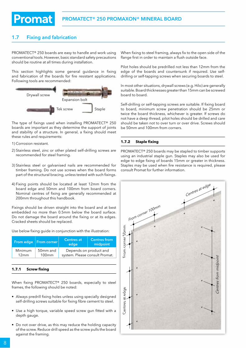
1.7 Fixing and fabrication
PROMATECT® 250 boards are easy to handle and work using conventional tools. However, basic standard safety precautions should be routine at all times during installation.
This section highlights some general guidance in fixing and fabrication of the boards for fire resistant applications. Following tools are recommended:
Drywall screw Expansion bolt
Tek screw Staple
The type of fixings used when installing PROMATECT® 250 boards are important as they determine the support of joints and stability of a structure. In general, a fixing should meet these rules and requirements:
1) Corrosion resistant.
2) Stainless steel, zinc or other plated self-drilling screws are recommended for steel framing.
3) Stainless steel or galvanised nails are recommended for timber framing. Do not use screws when the board forms part of the structural bracing, unless tested with such fixings.
4) Fixing points should be located at least 12mm from the board edge and 50mm and 100mm from board corners. Nominal centres of fixing are generally recommended at 200mm throughout this handbook.
Fixings should be driven straight into the board and at best embedded no more than 0.5mm below the board surface. Do not damage the board around the fixing or at its edges. Cracked sheets should be replaced.
Use below fixing guide in conjunction with the illustration:
From edge From cornerCentres at
edgeCentres from
midpoint
Minimum 12mm
50mm and 100mm
Depends on product and system. Please consult Promat.
1.7.1 Screw fixing
When fixing PROMATECT® 250 boards, especially to steel frames, the following should be noted:
• Always predrill fixing holes unless using specially designed self-drilling screws suitable for fixing fibre cement to steel.
• Use a high torque, variable speed screw gun fitted with a depth gauge.
• Do not over drive, as this may reduce the holding capacity of the screw. Reduce drill speed as the screw pulls the board against the framing.
When fixing to steel framing, always fix to the open side of the flange first in order to maintain a flush outside face.
Pilot holes should be predrilled not less than 12mm from the edge of the boards and countersunk if required. Use self-drilling or self-tapping screws when securing boards to steel.
In most other situations, drywall screws (e.g. Hilo) are generally suitable. Board thicknesses greater than 15mm can be screwed board to board.
Self-drilling or self-tapping screws are suitable. If fixing board to board, minimum screw penetration should be 25mm or twice the board thickness, whichever is greater. If screws do not have a deep thread, pilot holes should be drilled and care should be taken not to over turn or over drive. Screws should be 50mm and 100mm from corners.
1.7.2 Staple fixing
PROMATECT® 250 boards may be stapled to timber supports using an industrial staple gun. Staples may also be used for edge to edge fixing of boards 15mm or greater in thickness. Staples may be used when fire resistance is required, please consult Promat for further information.
Centres at edge
From corner 100mm
Cen
tres
from
mid
poin
tFrom
cor
ner 5
0mm
Cen
tres
at e
dge

PROMATECT® 250 PROMAXON® MINERAL BOARD
9
1.7.3 Forming holes
Apertures often need to be cut within a board to allow for penetration of services such as switchboxes, lights, access panels etc. The following procedures therefore serve as general guidelines only. Any method that allows for cutting of holes without damaging the board is acceptable.
1) For smooth, clean cut circular holes:
• Mark the centre of the hole on the board.
• Predrill a hole to be used as a guide.
• Cut the hole to the require diameter using a hole saw fitted to a heavy duty electric drill where the central bit is inserted into the predrilled hole or use a jigsaw.
2) For small irregular holes:
• Small rectangular apertures can be achieved by forming a series of small holes (using a drill) around the perimeter of the opening.
• Carefully tap out the waste piece from the panel face. Make sure that the edges are properly supported in order to avoid damage to boards.
• Rough edges can be cleaned with a rasp or 40 grit glass paper.
Below example of nailing and hammering for openings.
3) For large openings or apertures:
• Score deeply around the perimeter of the opening using a sharp tool (for thin boards only).
• Form a large round hole in the centre using the method previously described.
• Saw cut from the centre towards the corners of the opening.
• Tap waste pieces from the face side and if necessary clean rough edges with a rasp or with at least 40 grit sand paper. Radius corners with a half round rasp to eliminate any stress points.
Alternatively, for neater openings:
• Predrill a hole of at least 10mm diameter at the four corners of the openings. Mark lines from hole to hole (forming a rectangular shape) as a guide and cut along the lines using a jigsaw or hand saw.
• Clean rough edges of the hole with a rasp.
Apertures opening using alternative method: Never make holes by using heavy hammers, cold chisels or other “aggressive” methods. This will damage the underside of the boards and adversely effect the fi re performance of the system.

PROMATECT® 250 PROMAXON® MINERAL BOARD
10
1.8 Finishing
1.8.1 Plastering / skim coating
The preferred and best quality finishing method for PROMATECT® 250 protected steel members is to use a skim coat across the whole face of the board. External angles should be placed on each corner then a standard off the shelf skim coat system suitable for plasterboard be applied in accordance with the manufacturer’s recommendations.
PROMATECT® 250 boards have a high suction factor and while successful skim coats are relatively easy to obtain, some care is needed to retard the rapid drying of plaster coats, especially in areas of high temperature.
It is recommended that a small test area is plastered initially to ensure that the boards have been adequately sealed. Use of self-adhesive or hessian scrim applied over joints and internal angles is considerable. Paper scrim is not recommended. The bonding agent and plaster manufacturer’s recommendations must be followed at all times.
1.8.2 Tiling
PROMATECT® 250 boards can be tiled, provided due consideration is given to the installation of the boards and the requirements for additional framing prior to applying the tiles.
It should be noted that PROMATECT® 250 board application systems are used for their fire resistance performance. Therefore placing additional weight on an application system, such as ceramic or marble tiling for instance, can have significant effect on the overall fire resistance performance of the system.
As such, additional framing is required for partition systems etc which bear the weight of tiles in order to maintain the fire resistance performance.
As a general rule of thumb, partition systems to be tiled should be constructed with framing at nominal 450mm centres in both vertical and horizontal orientations. Minimum board thickness is applicable.
Care must be taken in sealing the boards thoroughly before applying any tile adhesive as the boards’ high suction load will accelerate the setting time of the tile adhesive.
1.8.3 Painting
All coatings should be supplied by a reputable manufacturer and their recommendations regarding surface preparation, sealing and finish coating should be followed at all times.
When using water based paints, a diluted first coat is recommended. For oil based paints a suitable alkali resisting primer should be used. Painted vapour barriers may be formed by the application of chlorinated rubber, epoxy resin or polyurethane paint.
The original smooth surface of PROMATECT® 250 boards can be painted with emulsion or oil based paints after applying with a universal primer. With water based paints, a diluted first coat should be applied. An alkali resisting primer is not required.
Depending on the type of finish required and the viewing circumstances (e.g. under glancing light), some minor surface imperfections of the painting result may occur.
Plastering the board joints in structural steelwork and the partitions (on background of the picture).
Applying tile adhesive on PROMATECT® 250 boards prior to tiling.

11
GENERAL INFORMATION OF STRUCTURAL STEEL FIRE PROTECTION
Numerous research programmes show that some types of fully stressed steel sections can achieve a 30 minute fire resistance without any additional protection materials being applied. However, these apply to a limited number of steel sections only, based on the allowable Section Factor Hp/A. Section Factor is a common term used in fire protection for steelwork and is discussed in detail below.
Typical building regulations usually require certain elements of structure to be fire resistant for more than 30 minutes and up to a specified minimum period of time. The thickness of any fire protection material depends on a number of factors, such as:
• Duration of fire resistance specified• Type of protection used, e.g. board, paint, spray etc• Perimeter of the part of steel section exposed to fire• Shape and dimensions of the steel section
To determine how these various factors affect the fire resistance, most Promat products and systems have been tested at nationally accredited laboratories around the world to a variety of standards. Tests carried out in accordance with these standards are performed on both loaded and unloaded beams and columns which are clad with fire protection material. Steel surface temperatures are monitored with thermocouples to assess the performance of the cladding. Steel that is fully stressed in accordance with the design guides BS 449 or BS 5950: Part 1, begin to lose their design margin of safety at temperatures around 550°C.
The table below shows how the strength of steel reduces as temperatures rise, i.e. variation of effective yield strength factor of normal structural steels with temperature.
Temperature (°C) 20 100 200 300 400 500 600 700 800
Effective yield strength factor
1.00 1.00 1.00 1.00 1.00 0.78 0.47 0.23 0.11
For example, at 700°C, the effective yield strength of Grade 43 (S275) steel is 0.23 x 275 = 63.25N/mm2.
A range of unloaded sections are also tested to obtain data for analytical calculation, to measure exactly how much protection is needed for the most common steel sections and for providing fire resistance for different time periods.
IMPORTANT: When using PROMATECT® 250 protection systems for structural steelwork, conservative limiting temperatures of 550°C and 620°C are referred to for columns and beams respectively and are in general use throughout this brochure. Apart from temperature data, the fire tests also need to demonstrate the ability of cladding to remain in place, usually described as the “stickability” of the material, for the maximum duration for which the protection may be required. The availability of thin materials and the low weight of Promat systems, plus the possibility of prefabrication, ensure maximum cost efficiency.
2.1 Section factor (Hp/A)
The degree of fire protection provided depends on the Hp/A Section Factor for the steel section. The Hp/A factor is a function of the area of the steel exposed to the fire and the
mass of the steel section. The higher the Hp/A, the faster the steel section heats up and so the greater the thickness of fire protection material required.
It should be noted that in European design standards, the section factor is presented as A/V which has the same numerical value as Hp/A. A/V measures the rate of temperature increase of a steel cross section by the ratio of the heated surface area to the volume. It is likely to gradually replace the use of Hp/A.
Depending on type of material used for protection, the calculation method for Hp/A value may differ. Generally there are two methods of construction for the protection materials: box protection and profile protection.
2.1.1 Box protection using board materials
For box protection, Hp is the sum of the inside dimensions of the smallest possible rectangular or square encasement of the steel section. One exception is circular hollow sections.
Where a steel section abuts or is built into a fire resisting wall or floor, the surface in contact with or the surface within the wall or floor is ignored when calculating Hp. See page 13. However, the value A is always the total cross sectional area of the whole steel section.
2.1.2 Castellated sections / cellform beams
These steel members heat up more quickly than the original section from which they were produced. Common practice is that protection thickness should therefore be 20% greater than those calculated from the Hp/A value of the original section from which the castellated section is formed.
However, it should be noted that the above information is now superseded by a new, more scientific approach for the protection of castellated sections. The following is taken from “Fire Protection for Structural Steel in Buildings”, 4th Edition, published by the ASFP (see www.asfp.org.uk).
The recently amended method of obtaining the section factor (Hp/A) for castellated sections is now specific. In fact, the recommendation from the Steel Construction Institute, published as RT 1085, for castellated sections and cellular beams manufactured from all rolled steel sections and from welded plate, the Section Factor for passive protection system is calculated as:
Section factor (m-1) = 1400/tWhere t = the thickness (mm) of the lower steel web and applies for beams made from all steel rolled sections and from welded steel plate.
It should be noted that there are a number of conditions attached to the use of this calculation method, which are detailed in the ASFP “Yellow Book” publication.
Individual protection products, normally quite similar in performance when compared on the basis of rolled steel sections, may require radically different thicknesses for the same cellular beam.

12
GENERAL INFORMATION OF STRUCTURAL STEEL FIRE PROTECTION
2.1.3 Structural hollow section
The same thickness of board materials can be used on square, rectangular and circular hollow sections as on ‘I’ sections of the same Hp/A value.
2.1.4 Bracing
Bracing is included in a structure to give resistance to wind forces and provide overall stiffness. Masonry walls and steel cladding contribute to a structure’s rigidity but these are rarely taken into account in design. Also, the probability of a major fire occurrence concurrent with maximum wind load is remote (see BS 5950: Part 8). It seems unreasonable therefore to apply the 550°C steel temperature criteria to bracing. While each case must be judged on individual merits, protection to bracing is generally not necessary, but where it is required the Hp/A value of the bracing section or 200m-1 should be used, whichever is the lesser.
2.1.5 Lattice members
As the determination of the protection necessary to protect lattice members requires broad consideration of the lattice design, please consult Promat concerning such steel sections.
2.1.6 Partially exposed members
Where columns or beams are partly built into or are in close contact with walls or floors, the protection afforded to the steelwork by the wall or floor should be taken into account. In those instances where the steel section sits within or against masonry or concrete constructions, this will give protection to the adjacent surface of the steelwork. Thus, for the purpose of determining the heated perimeter (Hp), this should be taken as only that part of the steel section which is exposed. It should be noted that where the steelwork penetrates both sides of a fire resisting construction, e.g. a wall protruding into a space which has an open end, simultaneous attack from fire on both sides may occur on columns partially exposed within the wall. In such an instance, the section factor should be calculated based upon the sum of the areas exposed to fire on either side of the wall and the total volume of the steel section.
Note that separating elements are generally required to offer a performance including the insulation criteria of 140°C or 180°C. Therefore, where a steel section passes through a separating element and is exposed on both sides, consideration must also be given to providing sufficient protection not only to maintain the temperature of the steel section below 550°C but also to ensure the surface temperature on the unexposed face does not exceed the 140°C or 180°C insulation criteria of the separating element. Due allowance for any expected building movement should also be considered.
2.1.7 External lightweight walls
Where the structural elements form portal legs supporting a lightweight external wall, the insulation performance required of the wall may contribute to the protection of any column
flange falling within the thickness of the wall. In such cases, please consult Promat to confirm the board thickness and which areas of such columns should be protected.
2.1.8 Internal lightweight partitions/walls
Where a column or beam is built into a fire resistant lightweight wall or partition, the protection to the steelwork can generally be designed on the assumption that only one side of the wall or partition will be exposed to fire at any one time. The wall or partition should be adequately secured to the column in such a way as to ensure the wall or partition will not apply stress on the protection encasement. Due allowance for any expected building movement should be considered.
2.1.9 Floors
Where beams are wholly within the cavity of a timber floor protected by a PROMATECT®-H ceiling, test evidence shows that the cavity air temperature of the floor is such that the beam will be adequately protected to the same fire resistance by the ceiling that protects the floor. Where the beam is wholly or partly below the line of the PROMATECT®-H ceiling then Hp should be based upon the portion of the steel beam that is below ceiling level.
2.1.10 Beams supporting composite floors with profiled metal decking
A series of fire resistance tests has demonstrated that it is not always necessary to fill the void formed between the top flange of a beam and the underside of a profiled steel deck. Recommendations based on the research have been published by the Steel Construction Institute (UK) and for decks running perpendicular to the beams, are as follows:
DOVETAIL DECKS
Voids may be left unfilled for all fire resistance period, unless a fire resisting wall or partition is located beneath the beam.
TRAPEZOIDAL DECKS
Generally, voids may be left unfilled for up to 60 minutes fire resistance. Also, for 90 minutes if the board thickness used is appropriate for the Hp/A + 15%. Care should be taken to ensure that if the voids are unfilled, the main encasement will need to be adequately secured. For periods over 90 minutes the voids should be filled.
In all instances, voids should also be filled if a fire wall is located beneath the beam, for all fire resistance periods. These recommendations apply to board encasements. The trapezoidal steel deck slab should be designed to act structurally with the beam. If this is not the case, the voids should be filled for all fire resistance periods.

B
D
B
B
B
B
D
D
D
D
D
13
GENERAL INFORMATION OF STRUCTURAL STEEL FIRE PROTECTION
2.2 Calculation of section factor (Hp/A ) for various box protection
Protection configurations with values of perimeter Hp for use in the calculation of section factor Hp/A (A/V)
Steel section Box protection
Universal beams, universal columns and joists (plain and cas- tellated)
Hp
Four sides
2B + 2D
Three sides
B + 2D
Three sides(partially exposed)
B + 2d
Two sides
B + D
One side(partially exposed)
B
Structural and rolled tees
Hp
Four sides
2B + 2D
Three sides(flange to soffit)
B + 2D
Three sides(toe of web to soffit)
B + 2D
Angles
Hp
Four sides
2B + 2D
Three sides(flange to soffit)
B + 2D
Three sides(toe of flange soffit)
B + 2D
Channels
Hp
Four sides
2B + 2D
Three sides(web to soffit)
2B + D
Three sides(flange to soffit)
B + 2D
Square or rectangularhollow sections
Hp
Four sides
2B + 2D
Three sides
B + 2D
Circularhollow sections
Hp
Four sides
πD
NOTE: The air space created in boxing a circular section improves the insulation and the value of Hp/A. Therefore, Hp higher than profile protection (p) would be anomalous. Hence, Hp is taken as the circumference of the circular section and not 4D.
Following is an example of calculation for a universal beam section using box protection of 305mm x 305mm x 240kg/m serial size to be encased on three or four sides when A = 305.6cm², B = 317.9mm, D = 352.6mm, t = 23mm.
Four sided profile protection: Three sided profile protection: Hp = 2B + 2D Hp = B + 2D = (2 x 317.9) + (2 x 352.6) = 317.9 + (2 x 352.6) = 1341mm (1.341m) = 1023.1mm (1.023m) Hp/A = 1.341 ÷ 0.03056 Hp/A = 1.023 ÷ 0.03056 = 43.9m-1 = 33.5m-1
The above calculated values are approximate in that radii at corners and roots of all sections are ignored. In these figures, Hp/A = A/V.

B
D
B
B
B
B
D
D
D
D
D
B
D
B
B
B
B
D
D
D
D
D
14
GENERAL INFORMATION OF STRUCTURAL STEEL FIRE PROTECTION
2.3 Guide of section factor (Hp/A) for encasement
2.3.1 Universal column cladding up to 120/-/- in accordance with the requirements of AS 1530: Part 4: 2005 (4-sided universal columns)
Section D B Weight Hp/ACritical temperature 550°C
30/-/- 60/-/- 90/-/- 120/-/-
310UC158 372 311 158.0 68 15mm 15mm 15mm 15mm
310UC137 321 309 137.0 72 15mm 15mm 15mm 20mm
310UC118 315 307 118.0 83 15mm 15mm 15mm 20mm
310UC97 308 305 96.8 99 15mm 15mm 15mm 20mm
250UC89 260 256 89.0 91 15mm 15mm 15mm 20mm
250UC73 254 254 73.0 109 15mm 15mm 15mm 25mm
200UC60 210 205 60.0 109 15mm 15mm 15mm 25mm
200UC52 206 204 52.2 123 15mm 15mm 20mm 25mm
200UC46 203 203 46.2 138 15mm 15mm 20mm 25mm
152UC37 162 154 37.2 133 15mm 15mm 20mm 25mm
152UC30 158 153 30.0 162 15mm 15mm 20mm 30mm
152UC23 152 152 23.4 205 15mm 15mm 25mm 35mm
100UC15 97 99 14.8 208 15mm 15mm 25mm 35mm
2.3.2 Hollow section column cladding up to 120/-/- in accordance with the requirements of AS 1530: Part 4: 2005 (4-sided hollow section columns)
Section D B Weight Hp/ACritical temperature 550°C
30/-/- 60/-/- 90/-/- 120/-/-
250 x 250 x 9 250 250 65.9 119 15mm 15mm 20mm 25mm
250 x 250 x 6 250 250 45.0 174 15mm 15mm 20mm 30mm
200 x 200 x 9 200 200 51.8 121 15mm 15mm 20mm 25mm
200x 200 x 6 200 200 35.6 176 15mm 15mm 20mm 30mm
200 x 200 x 5 200 200 29.9 210 15mm 15mm 25mm 35mm
150 x 150 x 9 150 150 37.7 125 15mm 15mm 20mm 25mm
150 x 150 x 6 150 150 26.2 180 15mm 15mm 20mm 30mm
150 x 150 x 5 150 150 22.1 213 15mm 15mm 25mm 35mm
125 x 125 x 9 125 125 30.6 128 15mm 15mm 20mm 25mm
125 x 125 x 6 125 125 21.4 183 15mm 15mm 20mm 30mm
125 x 125 x 5 125 125 18.2 216 15mm 15mm 25mm 35mm
100 x 100 x 9 100 100 23.5 134 15mm 15mm 20mm 25mm
100 x 100 x 6 100 100 16.7 188 15mm 15mm 25mm 30mm
100 x 100 x 5 100 100 14.2 221 15mm 15mm 25mm 35mm
89 x 89 x 6 89 89 14.7 190 15mm 15mm 25mm 30mm
89 x 89 x 5 89 89 12.5 224 15mm 15mm 25mm 35mm
75 x 75 x 6 75 75 12.0 196 15mm 15mm 25mm 30mm
75 x75 x 5 75 75 10.3 229 15mm 15mm 25mm 35mm
65 x 65 x 6 65 65 10.1 202 15mm 15mm 25mm 35mm
65 x 65 x 5 65 65 8.75 233 15mm 15mm 25mm 35mm

B
D
15
GENERAL INFORMATION OF STRUCTURAL STEEL FIRE PROTECTION
2.3 Guide of section factor (Hp/A) for encasement
2.3.3 Universal beam cladding up to 120/-/- in accordance with the requirements of AS 1530: Part 4: 2005 (3-sided universal beams)
Section D B Weight Hp/ACritical temperature 620°C
30/-/- 60/-/- 90/-/- 120/-/-
610UB125 612 229 125.0 91 15mm 15mm 15mm 20mm
610UB113 607 228 113.0 100 15mm 15mm 15mm 25mm
610UB101 602 228 101.0 111 15mm 15mm 15mm 25mm
530UB92 533 209 92.4 108 15mm 15mm 15mm 25mm
530UB82 528 209 82.0 121 15mm 15mm 20mm 25mm
460UB82 460 191 82.1 106 15mm 15mm 15mm 25mm
460UB74 457 190 74.6 116 15mm 15mm 20mm 25mm
460UB67 454 190 67.1 128 15mm 15mm 20mm 25mm
410UB60 406 178 59.7 130 15mm 15mm 20mm 25mm
410UB54 403 178 53.7 144 15mm 15mm 20mm 25mm
360UB57 359 172 57.0 122 15mm 15mm 20mm 25mm
360UB51 356 171 50.7 137 15mm 15mm 20mm 25mm
360UB45 352 171 44.7 154 15mm 15mm 20mm 30mm
310UB46 307 166 46.2 133 15mm 15mm 20mm 25mm
310UB40 304 165 40.4 150 15mm 15mm 20mm 30mm
310UB32 298 149 32.0 183 15mm 15mm 20mm 30mm
250UB37 256 146 37.3 139 15mm 15mm 20mm 25mm
250UB31 252 146 31.4 162 15mm 15mm 20mm 30mm
250UB25 248 124 25.7 189 15mm 15mm 20mm 30mm
200UB30 207 134 29.8 144 15mm 15mm 20mm 25mm
200UB25 203 133 25.4 167 15mm 15mm 20mm 30mm
200UB22 202 133 22.3 189 15mm 15mm 20mm 30mm
200UB18 198 99 18.2 214 15mm 15mm 20mm 30mm
180UB22 179 90 22.2 158 15mm 15mm 20mm 30mm
180UB18 175 90 18.1 191 15mm 15mm 20mm 30mm
180UB16 173 90 16.1 213 15mm 15mm 20mm 30mm
150UB18 155 75 18.0 168 15mm 15mm 20mm 30mm
150UB14 150 75 14.0 210 15mm 15mm 20mm 30mm
Above table provides information relating to the 3-sided encasement of steel beams where a concrete deck is directly supported onto the top flange of the beam, where the concrete acts as a heat sink and where the beams are generally not fully loaded, therefore a temperature of 620°C is considered appropriate.
Where the beam supports a floor of a different construction other than plain concrete, this failure temperature may not be applicable. If in doubt, please consult Promat or your local structural engineer.
CHAPTER
3
STR
UC
TUR
AL
STEE
L FI
RE
PR
OTE
CTI
ON

16
P250 AS00.12PROMATECT® 250 STRUCTURAL STEELFIRE PROTECTION HP/A RATIO
Hp/A ratio table 1 Up to 120/-/- fire resistance in accordance with the requirements of AS 1530: Part 4: 2005 (reports no. BRE P106900-1003) for structural steel column protection at critical temperature of 550°C
Fire resistancePROMATECT® 250 board thickness (mm)
15 18 20 22 25 27 28 30 32 33 34 35 36 37 38
30 minutes 260 260 260 260 260 260 260 260 260 260 260 260 260 260 260
60 minutes 260 260 260 260 260 260 260 260 260 260 260 260 260 260 260
90 minutes 114 153 185 223 260 260 260 260 260 260 260 260 260 260 260
120 minutes 68 87 102 118 145 165 176 201 228 243 260 260 260 260 260
Hp/A ratio table 2 Up to 120/-/- fire resistance in accordance with the requirements of AS 1530: Part 4: 2005 (reports no. BRE P106900-1003) for structural steel column protection at critical temperature of 620°C
Fire resistancePROMATECT® 250 board thickness (mm)
15 18 20 22 25 27 28 30 32 33 34 35 36 37 38
30 minutes 260 260 260 260 260 260 260 260 260 260 260 260 260 260 260
60 minutes 260 260 260 260 260 260 260 260 260 260 260 260 260 260 260
90 minutes 142 227 260 260 260 260 260 260 260 260 260 260 260 260 260
120 minutes 67 92 112 137 186 231 259 260 260 260 260 260 260 260 260
Hp/A ratio table 3 Up to 120/-/- fire resistance in accordance with the requirements of AS 1530: Part 4: 2005 (reports no. BRE P106900-1003) for structural steel beam protection at critical temperature of 550°C
Fire resistancePROMATECT® 250 board thickness (mm)
15 18 20 22 25 27 28 30 32 33 34 35 36 37 38
30 minutes 260 260 260 260 260 260 260 260 260 260 260 260 260 260 260
60 minutes 260 260 260 260 260 260 260 260 260 260 260 260 260 260 260
90 minutes 102 135 162 192 249 260 260 260 260 260 260 260 260 260 260
120 minutes — — 92 106 129 146 156 176 199 211 224 238 256 260 260
Hp/A ratio table 4 Up to 120/-/- fire resistance in accordance with the requirements of AS 1530: Part 4: 2005 (reports no. BRE P106900-1003) for structural steel beam protection at critical temperature of 620°C
Fire resistancePROMATECT® 250 board thickness (mm)
15 18 20 22 25 27 28 30 32 33 34 35 36 37 38
30 minutes 260 260 260 260 260 260 260 260 260 260 260 260 260 260 260
60 minutes 260 260 260 260 260 260 260 260 260 260 260 260 260 260 260
90 minutes 115 173 232 260 260 260 260 260 260 260 260 260 260 260 260
120 minutes — — 94 113 149 180 198 243 260 260 260 260 260 260 260

17
P250 AS01.12PROMATECT® 250STRUCTURAL STEEL COLUMN CLADDING
Up to 120/-/- fire resistance in accordance with the requirements of AS 1530: Part 4: 2005
1 PROMATECT® 250 board, thickness in accordance with the Hp/A ratio tables on page 16
2 100mm wide PROMATECT® 250 soldiers, minimum thickness similar to 1
3 Continuous galvanised steel channel 19mm x 38mm x 19mm x 0.8mm thick or equivalent, leg of each channel is located against inner surface of flange
4a Continuous galvanised steel angles minimum 32mm x 19mm x 0.8mm thick or equivalent fixed to the wall using non combustible proprietary anchors at nominal 500mm centres
4b Continuous galvanised steel angles minimum 32mm x 19mm x 0.8mm thick or similar fixed to the flange using Teks screws, shot fired nails or welding. Secure edges of side boards at 200mm centres
5 Horizontal joints in adjacent board sides to be staggered at minimum 300mm. For wide columns, it is advisable to include a PROMATECT® 250 cover strip behind the joints within the web of the steel column to provide additional impact resistance
6a Self-drilling or self-tapping drywall screws fixed to channel/angle at nominal 200mm centres. Screw length should be additional 20mm of the board thickness
6b Self-drilling or self-tapping drywall screws fixed to soldiers at nominal 100mm centres. Screw length should be additional 20mm of the board thickness
6c Steel wire staple fixings in accordance with table below. Care should be taken not to overtighten the screws. When edge fixing it is advisable to drill pilot holes, particularly with 15mm thick boards
Board thickness Steel wire staples at 100mm centres
15mm 44/10/1mm
20mm 44/10/1mm
25mm 50/10/1mm
30mm 60/10/1mm
7 Structural steel column 8 Concrete wall substrate
Four sided channel fixing
Three sided channel fixing
Three sided edge fixing
Four sided edge fixing
4b
6b
31
1
1
1
12
1
77
8
8
7
7
2
Min
imum
300
mm
6a
6a
6c
6c
6b
5
5
3
6a
4a
Min
imum
300
mm
18
P250 AS02.12PROMATECT® 250STRUCTURAL STEEL BEAM CLADDING
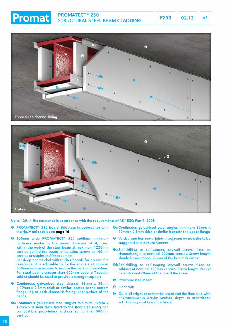
Up to 120/-/- fire resistance in accordance with the requirements of AS 1530: Part 4: 2005
1 PROMATECT® 250 board, thickness in accordance with the Hp/A ratio tables on page 16
2 100mm wide PROMATECT® 250 soldiers, minimum thickness similar to the board thickness of 1, fixed within the web of the steel beam at maximum 1220mm centres behind the board joints using screws at 100mm centres or staples at 50mm centres For deep beams clad with thicker boards for greater fire resistance, it is advisable to fix the soldiers at nominal 600mm centres in order to reduce the load on the soldiers. For steel beams greater than 600mm deep, a T-section soldier should be used to provide a stronger support
3 Continuous galvanised steel channel 19mm x 38mm x 19mm x 0.8mm thick or similar located at the bottom flange, leg of each channel is facing inner surface of the flange
4a Continuous galvanised steel angles minimum 32mm x 19mm x 0.8mm thick fixed to the floor slab using non combustible proprietary anchors at nominal 500mm centres
4a Continuous galvanised steel angles minimum 32mm x 19mm x 0.8mm thick or similar beneath the upper flange
5 Vertical and horizontal joints in adjacent board sides to be staggered at minimum 300mm
6a Self-drilling or self-tapping drywall screws fixed to channel/angle at nominal 200mm centres. Screw length should be additional 20mm of the board thickness
6b Self-drilling or self-tapping drywall screws fixed to soldiers at nominal 100mm centres. Screw length should be additional 20mm of the board thickness
7 Structural steel beam
8 Floor slab
9 Caulk all edges between the board and the floor slab with PROMASEAL®-A Acrylic Sealant, depth in accordance with the required board thickness
Three sided channel fixing
Option
9
2
3
2
32
2
1
1
1
1
7
7
8
8
6b
6b
5
5
6a
6a
4a
6b
6b
4b

19
P250 AS02.12PROMATECT® 250STRUCTURAL STEEL BEAM CLADDING
Up to 120/-/- fire resistance in accordance with the requirements of AS 1530: Part 4: 2005
1 PROMATECT® 250 board, thickness in accordance with the Hp/A ratio tables on page 16
2 100mm wide PROMATECT® 250 soldiers, minimum thickness similar to the board thickness of 1, fixed within the web of the steel beam at maximum 1220mm centres behind the board joints using screws at 100mm centres or staples at 50mm centres
For deep beams clad with thicker boards for greater fire resistance, it is advisable to fix the soldiers at nominal 600mm centres in order to reduce the load on the soldiers. For steel beams greater than 600mm deep, a T-section soldier should be used to provide a stronger support
3 Vertical and horizontal joints in adjacent board sides to be staggered at minimum 300mm
4a Self-drilling or self-tapping drywall screws fixed to soldiers at nominal 100mm centres. Screw length should be additional 20mm of the board thickness
4b Steel wire staple fixings in accordance with table below. Care should be taken not to overtighten the screws. When edge fixing it is advisable to drill pilot holes, particularly with 15mm thick boards
Board thicknessSteel wire staplesat 100mm centres
15mm 44/10/1mm
20mm 44/10/1mm
25mm 50/10/1mm
30mm 60/10/1mm
6 Structural steel beam
7 Floor slab
8 Caulk all edges between the board and the floor slab with PROMASEAL®-A Acrylic Sealant, depth in accordance with the required board thickness
Three sided edge fixing
7
2
2
5
6
5
4a
4b
4a
1

20
P250 AS01.1202.12
PROMATECT® 250 STRUCTURAL STEEL FIRE PROTECTIONARCHITECTURAL SPECIFICATIONS
Following are standard architectural specifications for structural steel column and beam protection using PROMATECT® 250. Please note that PROMATECT® 250 can be installed by using either screw or staple type of edge fixing. The end user must determine the suitability of any particular design to meet the performance requirements of any application before undertaking any work. If in doubt, please first obtain the advice from a suitably qualified engineer.
Where a column box encasement abuts a beam protected with a profiled fire protection system, e.g. intumescent paint, the column webs should be sealed at their tops using PROMATECT® 250. The installation methods described herein are suitable for steel sections up to 686mm deep and 325mm wide. For larger section or when protecting multiple sections within a single encasement, please consult Promat.
Fire exposure / area of application
Exposed faces of steelwork internal to building, for up to 120 minute fire resistance in accordance with the requirements of AS 1530: Part 4: 2005.
Location
________________________________________________________________________________________________________________(1)
Type of construction
____________ minutes(2) fire resistance to PROMATECT® 250 one sided, two sided, three sided or four sided encasement of structural steel columns and beams.
Lining boards
One layer of __________mm x __________mm(3) x __________mm(4) thick PROMATECT® 250 PROMAXON® mineral boards as manufactured by Promat, cut to size on-site/pre cut in accordance with the schedule of sizes(5) and fixed in accordance with the manufacturer’s recommended details and fixing instructions.
Screw fixing
For columns, PROMATECT® 250 boards to be fixed by board face to board edge using __________mm(6a) self-drilling, self-tapping screws at nominal 200mm centres.
For beams, vertical PROMATECT® 250 boards to be screwed to 100mm wide x __________mm(4) thick PROMATECT® 250 soldiers wedged between flanges at 1200mm centres using __________mm(6a) self-drilling, self-tapping screws at nominal 100mm centres. Where mechanical fixing is required for columns or beams, PROMATECT® 250 boards to be fixed by board face to board edge using __________mm(6a) self-drilling, self-tapping screws at nominal 200mm centres to nominal 19mm x 38mm x 19mm x 0.8mm continuous pressed steel channels or similar at bottom steel flange AND to 32mm x 19mm x 0.8mm continuous pressed steel angles secured to soffit of floor/roof slab or top steel flange. The angles should be fixed at nominal 500mm centres.
Staple fixing
For columns, PROMATECT® 250 boards to be fixed by board face to board edge using __________mm(6b) staples at nominal 100mm centres.
For beams, vertical PROMATECT® 250 boards to be screwed to 100mm wide x __________mm(4) thick PROMATECT® 250 soldiers wedged between flanges at 1200mm centres using __________mm(6b) staples at nominal 50mm centres. Where mechanical fixing is required for columns or beams, PROMATECT® 250 boards to be fixed by board face to board edge using __________mm(6b) staples at nominal 100mm centres to nominal 19mm x 38mm x 19mm x 0.8mm continuous pressed steel channels or similar at bottom steel flange AND to 32mm x 19mm x 0.8mm continuous pressed steel angles secured to soffit of floor/roof slab or top steel flange. The angles should be fixed at nominal 500mm centres.

21
P250 ASPROMATECT® 250 STRUCTURAL STEEL FIRE PROTECTIONARCHITECTURAL SPECIFICATIONS
01.1202.12
Board jointing for screw fixing
For beam casings only, PROMATECT® 250 board joints in the soffit to be backed with 100mm wide x minimum __________mm(4) thick PROMATECT® 250 internal cover strips secured with __________mm(7) self-drilling, self-tapping screws at nominal 100mm centres.
Board jointing for staple fixing
For beam casings only, PROMATECT® 250 board joints in the soffit to be backed with 100mm wide x minimum __________mm(4) thick PROMATECT® 250 internal cover strips secured with __________mm(7) staples to one side of board joint only.
Follow-on trades
Surface of boards to be prepared for painting/plastering/tiling(8) in accordance with manufacturer’s recommendations.
NOTES:• (1) insert location or provide steelwork drawing reference.• (2) insert required fire resistance level not exceeding 120 minutes.• (3) insert required thickness by reference to section factor (Hp/A) and fire resistance level.• (4) select board dimension on basis of economy in cutting. Standard board dimension is 2500mm x 1200mm.• (5), (8) delete as appropriate.• (6a) insert screw length which gives minimum 25mm penetration having regard to encasement thickness.• (6b) insert staple length which gives minimum 25mm penetration having regard to encasement thickness.• (7) insert screw length which is minimum 5mm longer than twice the encasement thickness.

PROMATECT® 250 PROMAXON® MINERAL BOARD
22
4 Safety data sheet (SDS)
4.1 Product information
PRODUCT NAME PROMATECT® 250
MARKETED BY Promat Australia Pty Ltd
EMERGENCY CONTACT NUMBER +61 (8) 8352 6759
USES Fire resistant building and construction applications
4.2 Hazards identification
CLASSIFICATION OF THE Not classified as hazardous according to Safe Work Australia Criteria.SUBSTANCE OR MIXTURE
LABEL ELEMENTS No signal word, pictograms, hazard or precautionary statements have been allocated.
OTHER HAZARDS No information provided.
4.3 Composition / Information on ingredients
INGREDIENT CAS NO. EC NO. CONTENTCALCIUM SILICATE 1344-95-2 215-710-8 >60%QUARTZ (CRYSTALLINE SILICA) 14808-60-7 238-878-4 <1%ADDITIVE(S) — — Not availableBINDING AGENT — — 6–30%
4.4 First aid measures
EYE CONTACT If in eyes, hold eyelids apart and flush continuously with running water. Continue flushing until advised to stop by a Poisons Information Centre (dial 13 11 26 Australia wide), a doctor or for at least 15 minutes.
INHALATION If inhaled, remove from contaminated area. Apply artificial respiration if not breathing.
SKIN CONTACT If skin or hair contact occurs, remove contaminated clothing and flush skin and hair with running water. Continue flushing with water until advised to stop by a Poisons Information Centre or a doctor.
INGESTION For advice, contact a Poisons Information Centre or a doctor at once. Due to product form and application, ingestion is considered unlikely.
FIRST AID FACILITIES None allocated.
MOST IMPORTANT SYMPTOMS & EFFECTS, BOTH ACUTE & DELAYED See Section 4.11 for more detailed information on health effects and symptoms.
IMMEDIATE MEDICAL ATTENTION & SPECIAL TREATMENT NEEDED Treat symptomatically.
This document has been compiled by Risk Management Technologies (RMT) on behalf of the manufacturer, importer or supplier of the product and serves as their safety data sheet (SDS). It is based on information concerning the product which has been provided to RMT by the manufacturer, importer or supplier or obtained from third party sources and is believed to represent the current state of knowledge as to the appropriate safety and handling precautions for the product at the time of issue. Further clarification regarding any aspect of the product should be obtained directly from the manufacturer, importer or supplier. While RMT has taken all due care to include accurate and up-to-date information in this SDS, it does not provide any warranty as to accuracy or completeness. As far as lawfully possible, RMT accepts no liability for any loss, injury or damage (including consequential loss) which may be suffered or incurred by any person as a consequence of their reliance on the information contained in this SDS. Version no. 3.0, dated 14th June 2017.

PROMATECT® 250 PROMAXON® MINERAL BOARD
23
4 Safety data sheet (SDS)
4.5 Fire fighting measures
EXTINGUISHING MEDIA Non flammable. Use an extinguishing agent suitable for the surrounding fire.
SPECIAL HAZARDS ARISING FROM THE SUBSTANCE OR MIXTURE Non flammable. May evolve toxic gases if strongly heated.
ADVICE FOR FIRE FIGHTERS Non flammable. No fire or explosion hazard exists.
HAZCHEM CODE None allocated.
4.6 Accidental release measures
PERSONAL PRECAUTIONS, PROTECTIVE EQUIPMENT & EMERGENCY PROCEDURES Wear Personal Protective Equipment (PPE) as detailed in Section 4.5.8.
ENVIRONMENTAL PRECAUTIONS Prevent product from entering drains and waterways.
METHODS OF CLEANING UP If spilt, collect and reuse where possible.
REFERENCE TO OTHER SECTIONS See Sections 4.8 & 4.13 for exposure controls and disposal.
4.7 Handling and storage
PRECAUTIONS Before use carefully read the product label. Use of safe work practices are recommended to avoid eye or skin contact and inhalation. Observe good personal hygiene, including washing hands before eating. Prohibit eating, drinking and smoking in contaminated areas.
CONDITIONS FOR SAFE STORAGE, INCLUDING ANY INCOMPATIBILITIES Store in a cool, dry, well ventilated area, removed from incompatible substances and
foodstuffs. Ensure containers are adequately labelled, protected from physical damage and sealed when not in use.
SPECIFIC END USE(S) No information provided.
4.8 Exposure controls / Personal protection
EXPOSURE STANDARDS
INGREDIENT REFERENCE TWA STELCALCIUM SILICATE (A) SWA (AUS) 10mg/m³ —QUARTZ (RESPIRABLE DUST) SWA (AUS) 0.1mg/m³ —
BIOLOGICAL LIMITS No biological limit values have been entered for this product.
This document has been compiled by Risk Management Technologies (RMT) on behalf of the manufacturer, importer or supplier of the product and serves as their safety data sheet (SDS). It is based on information concerning the product which has been provided to RMT by the manufacturer, importer or supplier or obtained from third party sources and is believed to represent the current state of knowledge as to the appropriate safety and handling precautions for the product at the time of issue. Further clarification regarding any aspect of the product should be obtained directly from the manufacturer, importer or supplier. While RMT has taken all due care to include accurate and up-to-date information in this SDS, it does not provide any warranty as to accuracy or completeness. As far as lawfully possible, RMT accepts no liability for any loss, injury or damage (including consequential loss) which may be suffered or incurred by any person as a consequence of their reliance on the information contained in this SDS. Version no. 3.0, dated 14th June 2017.

PROMATECT® 250 PROMAXON® MINERAL BOARD
24
4 Safety data sheet (SDS)
4.8 Exposure controls / Personal protection
EXPOSURE CONTROLS & PERSONAL PROTECTIVE EQUIPMENT
ENGINEERING CONTROLS Avoid inhalation. Use in well ventilated areas. Where an inhalation risk exists, mechanical extraction ventilation is recommended. Maintain dust levels below the recommended exposure standard.
EYE / FACE If cutting or sanding with potential for dust generation, wear dust-proof goggles.
HANDS If cutting or sanding with potential for dust generation, wear leather or cotton gloves.
BODY Not required under normal conditions of use.
RESPIRATORY If cutting or sanding with potential for dust generation, wear a Class P1 (Particulate) respirator.
4.9 Physical and chemical properties
INFORMATION ON BASIC PHYSICAL & CHEMICAL PROPERTIES
APPEARANCE Off white coloured boardODOUR OdourlessFLAMMABILITY Non flammableFLASH POINT Not relevantBOILING POINT Not availableMELTING POINT Not availableEVAPORATION RATE Not availablepH 9 (approximately)VAPOUR DENSITY Not availableSPECIFIC GRAVITY Not availableSOLUBILITY (WATER) InsolubleVAPOUR PRESSURE Not availableUPPER EXPLOSION LIMIT Not relevantLOWER EXPLOSION LIMIT Not relevantPARTITION COEFFICIENT Not availableAUTOIGNITION TEMPERATURE Not availableDECOMPOSITION TEMPERATURE Not availableVISCOSITY Not availableEXPLOSIVE PROPERTIES Not availableOXIDISING PROPERTIES Not availableODOUR THRESHOLD Not available
This document has been compiled by Risk Management Technologies (RMT) on behalf of the manufacturer, importer or supplier of the product and serves as their safety data sheet (SDS). It is based on information concerning the product which has been provided to RMT by the manufacturer, importer or supplier or obtained from third party sources and is believed to represent the current state of knowledge as to the appropriate safety and handling precautions for the product at the time of issue. Further clarification regarding any aspect of the product should be obtained directly from the manufacturer, importer or supplier. While RMT has taken all due care to include accurate and up-to-date information in this SDS, it does not provide any warranty as to accuracy or completeness. As far as lawfully possible, RMT accepts no liability for any loss, injury or damage (including consequential loss) which may be suffered or incurred by any person as a consequence of their reliance on the information contained in this SDS. Version no. 3.0, dated 14th June 2017.

PROMATECT® 250 PROMAXON® MINERAL BOARD
25
4 Safety data sheet (SDS)
4.10 Stability and reactivity
REACTIVITY Carefully review all information provided in Sections 4.2–4.6.
CHEMICAL STABILITY Stable under recommended conditions of storage.
POSSIBILITY OF HAZARDOUS Polymerization will not occur.REACTIONS
CONDITIONS TO AVOID Avoid heat, sparks, open flames and other ignition sources.
IMCOMPATIBLE MATERIALS Compatible with most commonly used materials.
HAZARDOUS DECOMPOSITION May evolve toxic gases if heated to decomposition.PRODUCTS
4.11 Toxicological information
ACUTE TOXICITY Based on available data, the classification criteria are not met.
SKIN Low irritant. Prolonged or repeated exposure to dust may result in irritation and dermatitis.
EYE Low irritant. Due to product form, the potential for exposure is reduced, unless cut or heated and dust or fumes generated.
SENSITISATION Not classified as causing skin or respiratory sensitisation.
MUTAGENICITY Not classified as a mutagen.
CARCINOGENICITY Not classified as a carcinogen. Adverse health effects, usually associated with long term exposure to high crystalline silica dust levels are not anticipated due to product form. This product may only present a hazard if the boards are cut or drilled with dust generation. Crystalline quartz is classified as carcinogenic to humans (IARC Group 1).
REPRODUCTIVE Not classified as a reproductive toxin.
STOT — SINGLE EXPOSURE Not classified as causing organ damage from single exposure. An inhalation hazard is not anticipated unless cut, drilled or sanded with dust generation, which may result in irritation of the nose and throat.
STOT — REPEATED EXPOSURE Not classified as causing organ damage from repeated exposure.
ASPIRATION This product does not present an aspiration hazard.
4.12 Ecological information
TOXICITY No information provided.PERSISTENCE & DEGRADABILITY No information provided.BIOACCUMULATIVE POTENTIAL No information provided.MOBILITY IN SOIL No information provided.OTHER ADVERSE EFFECTS No information provided.
This document has been compiled by Risk Management Technologies (RMT) on behalf of the manufacturer, importer or supplier of the product and serves as their safety data sheet (SDS). It is based on information concerning the product which has been provided to RMT by the manufacturer, importer or supplier or obtained from third party sources and is believed to represent the current state of knowledge as to the appropriate safety and handling precautions for the product at the time of issue. Further clarification regarding any aspect of the product should be obtained directly from the manufacturer, importer or supplier. While RMT has taken all due care to include accurate and up-to-date information in this SDS, it does not provide any warranty as to accuracy or completeness. As far as lawfully possible, RMT accepts no liability for any loss, injury or damage (including consequential loss) which may be suffered or incurred by any person as a consequence of their reliance on the information contained in this SDS. Version no. 3.0, dated 14th June 2017.

PROMATECT® 250 PROMAXON® MINERAL BOARD
26
4 Safety data sheet (SDS)
4.13 Disposal considerations
WASTE DISPOSAL Reuse where possible. No special precautions are normally required when handling this product.
LEGISLATION Dispose of in accordance with relevant local legislation.
4.14 Transport information
NOT CLASSIFIED AS A DANGEROUS GOOD BY THE CRITERIA OF THE ADG CODE, IMDG OR IATA.
TRANSPORT TYPE LAND (ADG) SEA (IMDG / IMO) AIR (IATA / ICAO)UN NUMBER None allocated None allocated None allocatedPROPER SHIPPING NAME None allocated None allocated None allocatedTRANSPORT HAZARD CLASS None allocated None allocated None allocatedPACKING GROUP None allocated None allocated None allocated
ENVIRONMENTAL HAZARDSENVIRONMENTAL HAZARDS No information provided.
SPECIAL PRECAUTIONS FOR USERHAZCHEM CODE None allocated.
4.15 Regulatory information
SAFETY, HEALTH AND ENVIRONMENTAL REGULATIONS/LEGISLATION SPECIFIC FOR THE SUBSTANCE OR MIXTURE
POISON SCHEDULE A poison schedule number has not been allocated to this product using the criteria in the Standard for the Uniform Scheduling of Medicines and Poisons (SUSMP).
CLASSIFICATIONS Safework Australia criteria is based on the Globally Harmonised System (GHS) of Classification and Labelling of Chemicals. The classifications and phrases listed below are based on the Approved Criteria for Classifying Hazardous Substances [NOHSC: 1008(2004)].
HAZARD CODES None allocated.
RISK PHRASES None allocated.
SAFETY PHRASES None allocated.
INVENTORY LISTING(S) AUSTRALIA: AICS (Australian Inventory of Chemical Substances) All components are listed on AICS, or are exempt.
This document has been compiled by Risk Management Technologies (RMT) on behalf of the manufacturer, importer or supplier of the product and serves as their safety data sheet (SDS). It is based on information concerning the product which has been provided to RMT by the manufacturer, importer or supplier or obtained from third party sources and is believed to represent the current state of knowledge as to the appropriate safety and handling precautions for the product at the time of issue. Further clarification regarding any aspect of the product should be obtained directly from the manufacturer, importer or supplier. While RMT has taken all due care to include accurate and up-to-date information in this SDS, it does not provide any warranty as to accuracy or completeness. As far as lawfully possible, RMT accepts no liability for any loss, injury or damage (including consequential loss) which may be suffered or incurred by any person as a consequence of their reliance on the information contained in this SDS. Version no. 3.0, dated 14th June 2017.

PROMATECT® 250 PROMAXON® MINERAL BOARD
27
4 Safety data sheet (SDS)
4.16 Other information
ADDITIONAL INFORMATION RESPIRATORS In general the use of respirators should be limited and engineering controls employed to avoid exposure. If respiratory equipment must be worn ensure correct respirator selection and training is undertaken. Remember that some respirators may be extremely uncomfortable when used for long periods. The use of air powered or air supplied respirators should be considered where prolonged or repeated use is necessary.
PERSONAL PROTECTIVE EQUIPMENT GUIDELINES The recommendation for protective equipment contained within this report is provided as a guide only. Factors such as method of application, working environment, quantity used, product concentration and the availability of engineering controls should be considered before final selection of personal protective equipment is made.
HEALTH EFFECTS FROM EXPOSURE It should be noted that the effects from exposure to this product will depend on several
factors including: frequency and duration of use; quantity used; effectiveness of control measures; protective equipment used and method of application. Given that it is impractical to prepare a report which would encompass all possible scenarios, it is anticipated that users will assess the risks and apply control methods where appropriate.
ABBREVIATIONS ACGIH American Conference of Governmental Industrial Hygienists
CAS # Chemical Abstract Service number used to uniquely identify chemical compounds
CNS Central Nervous System
EC No. European Community Number
EMS Emergency Schedules (emergency procedures for ships carrying dangerous goods)
GHS Globally Harmonized System
GTEPG Group Text Emergency Procedure Guide
IARC International Agency for Research on Cancer
LC50 Lethal Concentration, 50% / Median Lethal Concentration
LD50 Lethal Dose, 50% / Median Lethal Dose
mg/m³ Milligrams per cubic metre
OEL Occupational Exposure Limit
pH Relates to hydrogen ion concentration using a scale of 0 (high acidic) to 14 (highly alkaline)
ppm Parts per million
STEL Short-Term Exposure Limit
STOT-RE Specific target organ toxicity (repeated exposure)
STOT-SE Specific target organ toxicity (single exposure)
SUSMP Standard for the Uniform Scheduling of Medicines and Poisons
SWA Safe Work Australia
TLV Threshold Limit Value
TWA Time Weighted Average
PREPARED BY Risk Management Technologies 5 Ventnor Ave, West Perth, WA 6005 T +61 (8) 9322 1711 F +61 (8) 9322 1794 E [email protected] www.rmt.com.au.
This document has been compiled by Risk Management Technologies (RMT) on behalf of the manufacturer, importer or supplier of the product and serves as their safety data sheet (SDS). It is based on information concerning the product which has been provided to RMT by the manufacturer, importer or supplier or obtained from third party sources and is believed to represent the current state of knowledge as to the appropriate safety and handling precautions for the product at the time of issue. Further clarification regarding any aspect of the product should be obtained directly from the manufacturer, importer or supplier. While RMT has taken all due care to include accurate and up-to-date information in this SDS, it does not provide any warranty as to accuracy or completeness. As far as lawfully possible, RMT accepts no liability for any loss, injury or damage (including consequential loss) which may be suffered or incurred by any person as a consequence of their reliance on the information contained in this SDS. Version no. 3.0, dated 14th June 2017.

© P
rom
at A
ustr
alia
Pty
Ltd
. P25
0.00
–AU
201
7/09
Promat Australia Pty Ltd
Head office
1 Scotland RoadMile End South, SA 5031T 1800 PROMAT (776 628)F +61 (8) 8352 1014
New South Wales office
Unit 1, 175 Briens RoadNorthmead, NSW 2152T 1800 PROMAT (776 628)F +61 (2) 9630 0258
Victoria office
Suite 205, 198 Harbour EsplanadeDocklands, VIC 3008T 1800 PROMAT (776 628)F 1800 334 598
Queensland office
433 Logan RoadStones Corner, QLD 4120T 1800 011 376F 1800 334 598
www.promat.com.au
Etex is a Belgian industrial group that specialises and markets high quality building materials and systems. Founded since 1905 and headquartered in Brussels, Belgium, Etex currently operates in 123 factories and 116 subsidiaries across 44 countries, employs more than 18,000 people and is one of the largest fibre cement producers in the world.
Through its subsidiaries, the group offers an extensive range of products: small and large roofing materials, cladding and building boards, passive fire protection systems.
Etex aims to be a professional, solid partner for all kinds of building projects.
• The technical data provided in this publication is based on mean values prevalent at time of publication and is thus subject to fluctuation. It should not be regarded as a guarantee to system performance.
• All data contained herein conforms to and frequently surpasses generally accepted fire protection standards recognised by most professional fire science practitioners and regulatory authorities worldwide. The same general principle is equally applicable to all Promat products and systems. Promat has access to a considerable body of test authentication data and this can be provided on a complimentary basis upon request. It should be noted however that this publication replaces all previous editions in its entirety. Any form of reproduction by any means — manual, electronic, digital or otherwise — is strictly prohibited and subject to prior approval in writing from Promat. All rights related or connected to the Promat logo, Promat registered trademarks, featured illustrations, written information and technical reports in this publication are the sole, exclusive and copyright property of Promat and its legal partner companies.