project x: a multi-mw proton source at fermilab · project x: a multi-mw proton source at fermilab...
TRANSCRIPT
Project X: A multi-MW Proton Source at Fermilab
Steve HolmesExtreme Beam Lecture Series
J 11 2009June 11, 2009

OutlineOutline
• Strategic Context/Evolution of the Fermilab Complex
• Project X Goals and Initial Configuration
• Project X Research, Design, and Development Plan
• Relationships to other Programs
• Alternative Configurations
Project X website: http://projectx.fnal.gov/
Page 2Extreme BEAM, June 11, 2009 - S. Holmes

Strategic Context: Fermilab d th W ld Pand the World Program
Fermilab currently operates the highest energy collider, and the highest power long baseline neutrino beam, in the world.highest power long baseline neutrino beam, in the world.In 2009:
• LHC will capture the energy frontier• J-PARC will initiate a competitive neutrino program
Page 3Extreme BEAM, June 11, 2009 - S. Holmes

Strategic Context: Fermilab Long Range Plan
• Fermilab is the sole remaining U S laboratory providing facilities• Fermilab is the sole remaining U.S. laboratory providing facilities in support of accelerator-based Elementary Particle Physics.
• The Fermilab long-termstrategy is fully alignedwith the HEPAP/P5 plan:− Energy and intensity frontiers
h t lishare strong reliance onaccelerators
(www.science.doe.gov/hep/files/pdfs/P5_Report%2006022008.pdf)
Page 4Extreme BEAM, June 11, 2009 - S. Holmes
Strategic Context: The W ld i 2012World in ~2012
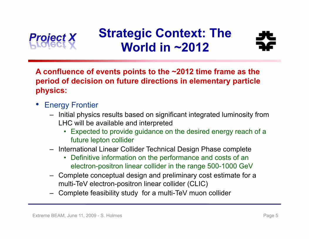
A confluence of events points to the ~2012 time frame as the
• Energy Frontier
pperiod of decision on future directions in elementary particle physics:
• Energy Frontier– Initial physics results based on significant integrated luminosity from
LHC will be available and interpreted• Expected to provide guidance on the desired energy reach of a p p g gy
future lepton collider– International Linear Collider Technical Design Phase complete
• Definitive information on the performance and costs of an electron positron linear collider in the range 500 1000 GeVelectron-positron linear collider in the range 500-1000 GeV
– Complete conceptual design and preliminary cost estimate for a multi-TeV electron-positron linear collider (CLIC)
– Complete feasibility study for a multi-TeV muon colliderComplete feasibility study for a multi TeV muon collider
Page 5Extreme BEAM, June 11, 2009 - S. Holmes

Strategic Context: The W ld i 2012
• Intensity Frontier
World in ~2012
Intensity Frontier– J-PARC operational at up to 750 kW beam power at 30-40 GeV in
support of the T2K long baseline (295 km) neutrino experiment– NOA long baseline (810 km) neutrino experiment initiates
operations at up to 700 kW beam power at 120 GeV at Fermilab– Complete design of a very long baseline (1300 km) neutrino
beamline at Fermilab, and an associated multi-MW proton sourceComplete conceptual design of a J PARC multi MW upgrade– Complete conceptual design of a J-PARC multi-MW upgrade
– Next round of neutrino experiments indicate whether the mixing parameter sin2213 is greater than or less than ~0.02
Page 6Extreme BEAM, June 11, 2009 - S. Holmes
Strategic Context: Evolution f th A l t C lof the Accelerator Complex
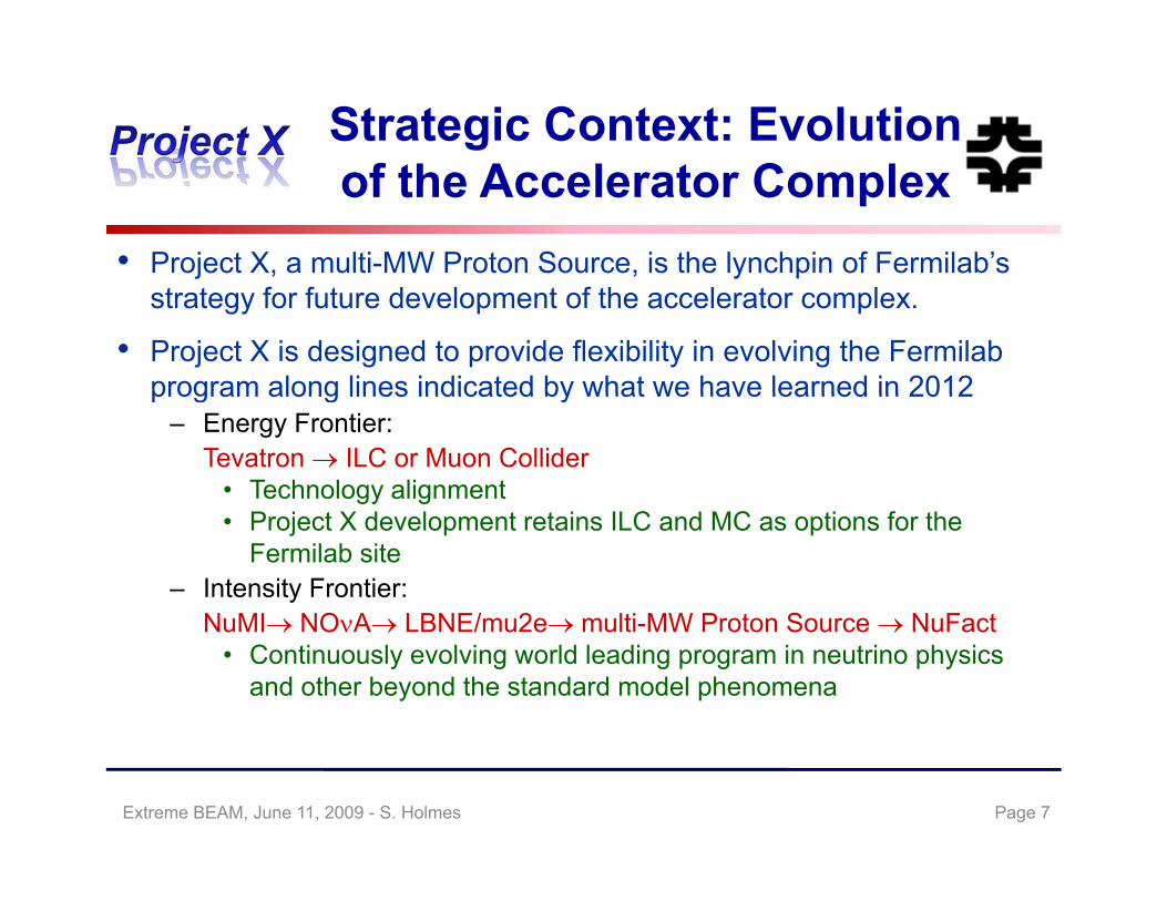
• Project X, a multi-MW Proton Source, is the lynchpin of Fermilab’sstrategy for future development of the accelerator complex.
• Project X is designed to provide flexibility in evolving the Fermilab program along lines indicated by what we have learned in 2012program along lines indicated by what we have learned in 2012
– Energy Frontier:Tevatron ILC or Muon Collider
• Technology alignment• Project X development retains ILC and MC as options for the
Fermilab site– Intensity Frontier:
NuMI NOA LBNE/mu2e multi MW Proton Source NuFactNuMI NOA LBNE/mu2e multi-MW Proton Source NuFact• Continuously evolving world leading program in neutrino physics
and other beyond the standard model phenomena
Page 7Extreme BEAM, June 11, 2009 - S. Holmes
Strategic Context: Shared T h l iTechnologies
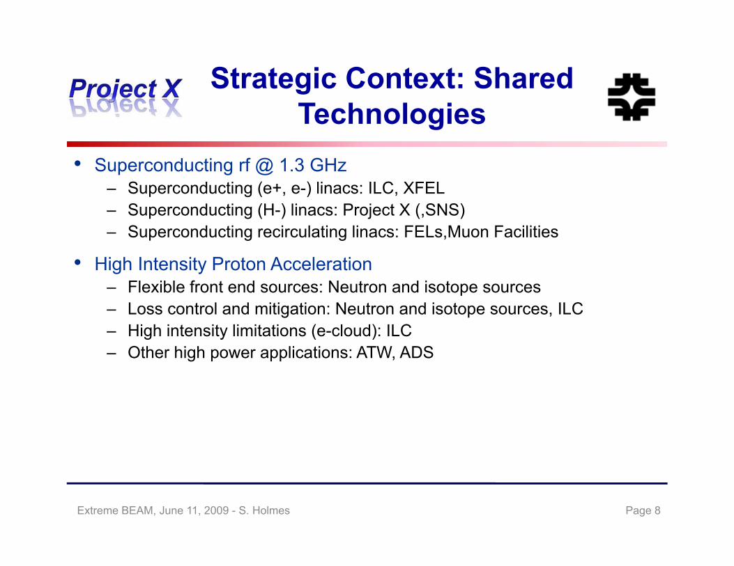
• Superconducting rf @ 1.3 GHz– Superconducting (e+, e-) linacs: ILC, XFEL– Superconducting (H-) linacs: Project X (,SNS)– Superconducting recirculating linacs: FELs,Muon Facilities
• High Intensity Proton Acceleration– Flexible front end sources: Neutron and isotope sources – Loss control and mitigation: Neutron and isotope sources, ILC– High intensity limitations (e-cloud): ILC– Other high power applications: ATW, ADS
Page 8Extreme BEAM, June 11, 2009 - S. Holmes
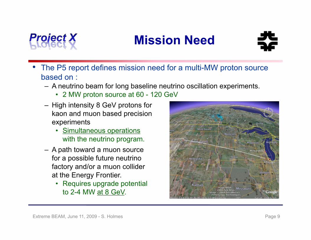
Mission Needss o eed
• The P5 report defines mission need for a multi-MW proton source b dbased on :– A neutrino beam for long baseline neutrino oscillation experiments.
• 2 MW proton source at 60 - 120 GeVHigh intensity 8 GeV protons for– High intensity 8 GeV protons forkaon and muon based precisionexperiments• Simultaneous operations
with the neutrino program.– A path toward a muon source
for a possible future neutrinofactory and/or a muon colliderfactory and/or a muon colliderat the Energy Frontier.• Requires upgrade potential
to 2-4 MW at 8 GeV.
Page 9Extreme BEAM, June 11, 2009 - S. Holmes
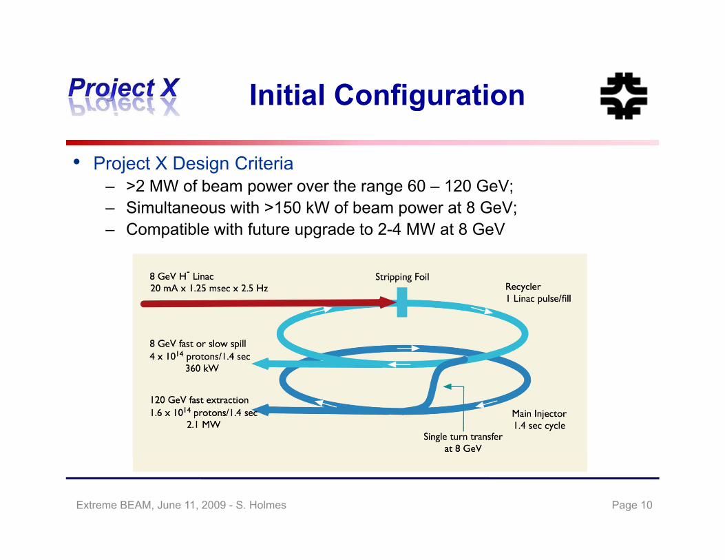
Initial ConfigurationInitial Configuration
• Project X Design Criteria– >2 MW of beam power over the range 60 – 120 GeV;– Simultaneous with >150 kW of beam power at 8 GeV;– Compatible with future upgrade to 2-4 MW at 8 GeV
Page 10Extreme BEAM, June 11, 2009 - S. Holmes
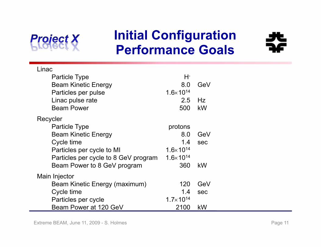
Initial ConfigurationP f G lPerformance Goals
LinacParticle Type H-Particle Type HBeam Kinetic Energy 8.0 GeVParticles per pulse 1.61014
Linac pulse rate 2.5 HzBeam Power 500 kWBeam Power 500 kW
RecyclerParticle Type protonsBeam Kinetic Energy 8.0 GeVCycle time 1.4 secParticles per cycle to MI 1.61014
Particles per cycle to 8 GeV program 1.61014
Beam Power to 8 GeV program 360 kW
Main InjectorBeam Kinetic Energy (maximum) 120 GeVCycle time 1.4 secParticles per cycle 1.71014Particles per cycle 1.710Beam Power at 120 GeV 2100 kW
Page 11Extreme BEAM, June 11, 2009 - S. Holmes
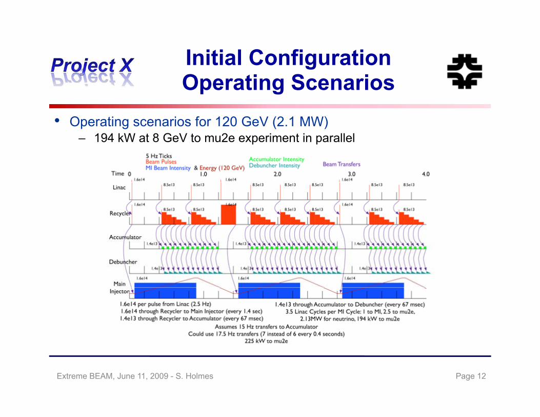
Initial Configuration O ti S iOperating Scenarios
• Operating scenarios for 120 GeV (2.1 MW)– 194 kW at 8 GeV to mu2e experiment in parallel
Page 12Extreme BEAM, June 11, 2009 - S. Holmes
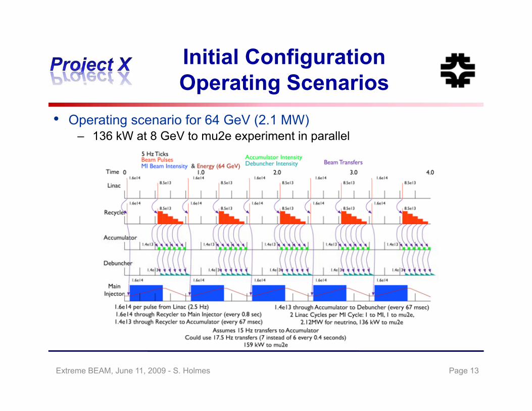
Initial Configuration O ti S iOperating Scenarios
• Operating scenario for 64 GeV (2.1 MW)– 136 kW at 8 GeV to mu2e experiment in parallel
Page 13Extreme BEAM, June 11, 2009 - S. Holmes
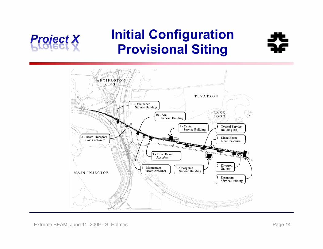
Initial ConfigurationP i i l SitiProvisional Siting
Page 14Extreme BEAM, June 11, 2009 - S. Holmes

Initial ConfigurationO ti l Ch llOperational Challenges
• We know that the IC does not provide an ideal platform for mounting a low energy flavor program.
– “Golden Book” requirements:
– The Recycler is ill-suited to providing high intensity slow spilled beam• In the IC the Recycler delivers 15 Hz packets to the Debuncher for
slow spill to mu2e. The Debuncher appears limited to <150 kW in this mode– The Debuncher appears limited to <150 kW in this mode
– The IC does not yet have a solution for the kaon requirements
We are able to generate substantially more beam power in the ICD h ff i l ili
Extreme BEAM, June 11, 2009 - S. Holmes Page 15
than we are effectively utilize.

Near-term StrategyNear term Strategy
• Develop an Initial Configuration Document– Meeting the high level design criteria– ICD subject to configuration control Released V1.1, March 2009: available at http://projectx.fnal.gov/
• Revise/update the current RD&D Plan– Based on the ICD– Review existing plan to emphasize reduction of risk Released V2.2, March 2009 following mid-February AAC evaluation
• Create a preliminary cost range estimate– Based on the ICDBased on the ICD Complete and subject of Director’s Review March 16-17, 2009
Page 16Extreme BEAM, June 11, 2009 - S. Holmes

Near-term StrategyNear term Strategy
• Establish design criteria and operating scenarios for evaluation of alternative configurations
– Design criteria complete– Alternative configuration under development
• Establish a multi-institutional collaboration for the RD&D phase – Collaboration established
• CD 0 in 2009• CD-0 in 2009– Based on: ICD, preliminary cost estimate, P5 mission definition– Coordinated with very long baseline and mu2e
Page 17Extreme BEAM, June 11, 2009 - S. Holmes

RD&D PlanRD&D Plan
• The primary goal of the Project X Research, Design, and Development (RD&D) program is to complete a fully developed baseline scope, cost estimate, and schedule in 2012 (CD-2).
– Design and technical component development;F ll d l d b li t ti t d h d l– Fully developed baseline scope, cost estimate, and schedule;
– Undertaken by a multi-institutional collaboration capable of executing both the RD&D plan and the follow-on construction project
• Secondary goals:– Coordinate Project X and ILC SCRF development programs;– Retain alignment of Project X and the Neutrino Factory and Muon
Collider programs to assure that Project X could serve as the initialCollider programs, to assure that Project X could serve as the initial stage of either/both facilities
Page 18Extreme BEAM, June 11, 2009 - S. Holmes
RD&D Plan: Accelerator Ch llChallenges
• Linac (325 MHz)– Front end: Peak current 32 mA x 1.25 msec x 5 Hz
• Consistent with SNS performance– High speed chopping (325 MHz)
• Variable chopping patterns• Variable chopping patterns– Consideration of warm vs. cold front end
• 30-60 MeV cold front end currently under development (HINS)
• Linac (1300 GHz)• Linac (1300 GHz)– 32 mA peak (20 mA average) x 1.25 msec x 5 Hz
• 3 times the charge/pulse of ILC– 25 MV/m gradient25 MV/m gradient– RF control of multiple accelerating structures from single rf source
Page 19Extreme BEAM, June 11, 2009 - S. Holmes
RD&D Plan: Accelerator Ch llChallenges
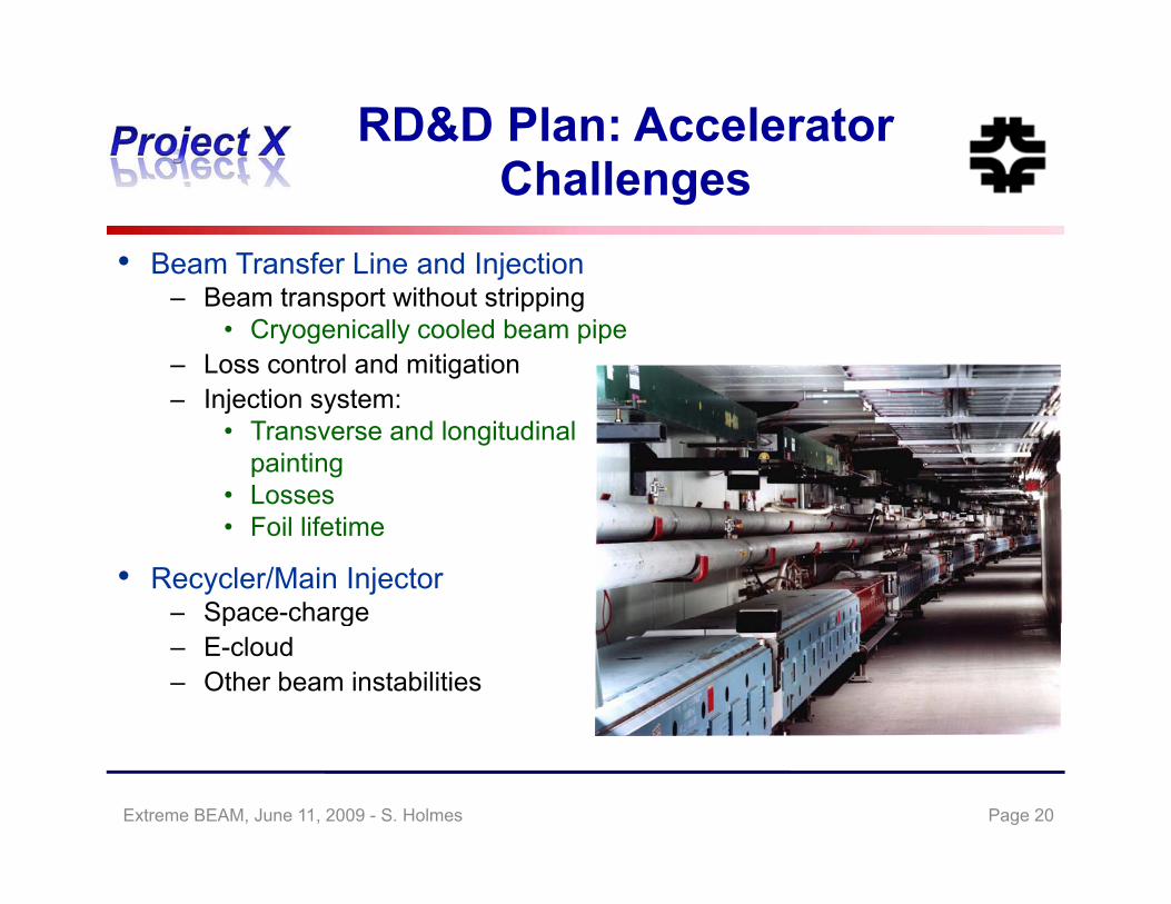
• Beam Transfer Line and Injection– Beam transport without stripping
• Cryogenically cooled beam pipe– Loss control and mitigation
Injection system:– Injection system:• Transverse and longitudinal
painting• Losses• Foil lifetime
• Recycler/Main Injector– Space-chargep g– E-cloud– Other beam instabilities
Page 20Extreme BEAM, June 11, 2009 - S. Holmes
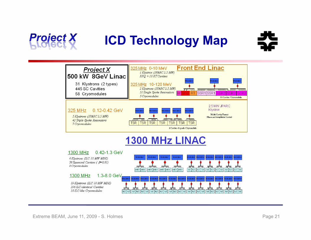
ICD Technology MapICD Technology Map
Page 21Extreme BEAM, June 11, 2009 - S. Holmes

Joint PX/HINS StrategyJoint PX/HINS Strategy
• The High Intensity Neutrino Source (HINS) program was established in 2006 to pursue a new approach to high intensity, low energy ion acceleration
• HINS primary goals:HINS primary goals:– Accelerate an axially symmetric beam (solenoidal focusing) to 30 MeV,
utilizing superconducting rf technology beyond 10 MeV– Demonstrate effectiveness of RF modulators for phase and amplitude
control of individual cavities fed by a common rf source• Intermediate goal is 6 cavity (warm) test with beam, demonstrating
viability of vector modulator technology, in early 2010– Demonstrate high-speed (nsec) beam chopping at 2 5 MeV– Demonstrate high-speed (nsec) beam chopping at 2.5 MeV
Goal is to complete facility (@30 MeV) in 2012
Page 22Extreme BEAM, June 11, 2009 - S. Holmes
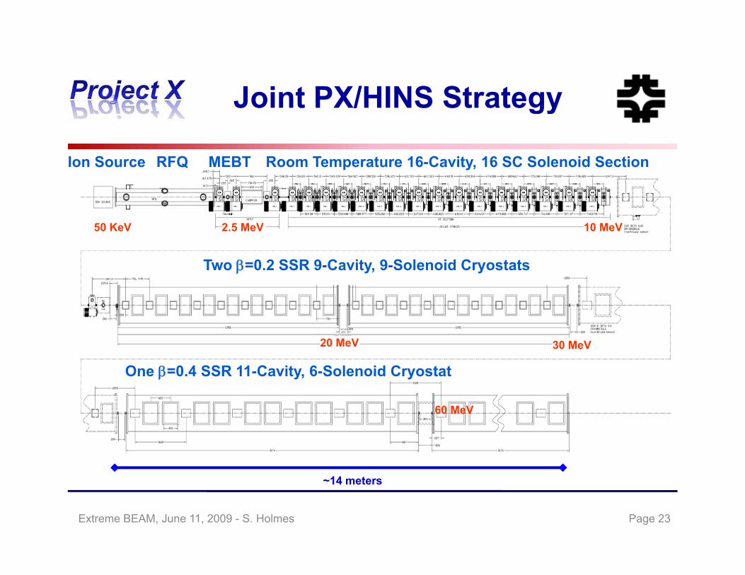
Joint PX/HINS StrategyJoint PX/HINS Strategy
Ion Source RFQ MEBT Room Temperature 16-Cavity, 16 SC Solenoid Section
2.5 MeV50 KeV 10 MeV
Two =0.2 SSR 9-Cavity, 9-Solenoid Cryostats
One =0.4 SSR 11-Cavity, 6-Solenoid Cryostat
20 MeV 30 MeV
60 MeV
~14 meters
Page 23Extreme BEAM, June 11, 2009 - S. Holmes

Joint PX/HINS StrategyJoint PX/HINS Strategy
• HINS Progress( )– Ion source (H+) installed and operating
– RFQ received and under rf testing (issues identified)– Room temperature spoke resonators tested
Prototype VMs tested– Prototype VMs tested– Two β = 0.22, 325 MHz, SSRs successfully tested in the VTS – Requirements: >10 MV/m @ Q0>5E8 @ 4 K
HINS SSR1 02 Q EHINS SSR1-02 - Q0 vs E
1.E+10
1.E+110
1.E+01
1.E+02
(mR/h
r)
Q @ 4K after 2K run Radiation @ 4K after 2K run
Test reuslts for 4.4K after 2K tests. Tested 3/3/2009
Design Goal
Achieved at 2°K !!!
1.E+07
1.E+08
1.E+09Q0
1.E-02
1.E-01
1.E+00
Rad
iatio
n
Design Goal
0 5 10 15 20 25 30 35
Gradient (MV/m)
Page 24Extreme BEAM, June 11, 2009 - S. Holmes
Joint PX/HINS StrategyJoint PX/HINS Strategy
• HINS is a candidate for the Project X front end, either in initial or upgraded configuration
– Designed for 27 mA x 1 msec x 10 Hz– ICD utilizes HINS as front end
f– Alternative is a conventional warm front end up to 100-200 MeV
• We expect to make a decision on utilization of HINS as Project X front end in 12-18 months
– Decision based on performance/cost comparison of HINS and warm technologies
– Decision will included results from the 6 cavity vector modulator demonstration testing of individual SSR1 cryomodule and simulationsdemonstration, testing of individual SSR1 cryomodule, and simulations
– Decision will include assessment of impact on upgrade potential of Project X to multi-MW at 8 GeV
Page 25Extreme BEAM, June 11, 2009 - S. Holmes
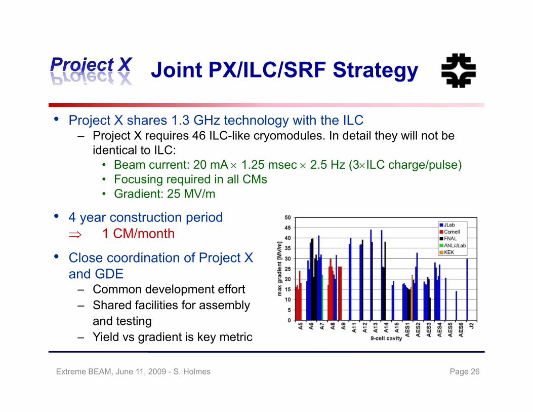
Joint PX/ILC/SRF StrategyJoint PX/ILC/SRF Strategy
• Project X shares 1.3 GHz technology with the ILC– Project X requires 46 ILC-like cryomodules. In detail they will not be
identical to ILC:• Beam current: 20 mA 1.25 msec 2.5 Hz (3ILC charge/pulse)• Focusing required in all CMs• Focusing required in all CMs• Gradient: 25 MV/m
• 4 year construction period 1 CM/month 1 CM/month
• Close coordination of Project Xand GDE
– Common development effort – Shared facilities for assembly
and testingYield vs gradient is key metric– Yield vs gradient is key metric
Page 26Extreme BEAM, June 11, 2009 - S. Holmes

SRF DevelopmentS f 9 ll V ti l T t i U SSummary of 9-cell Vertical Tests in U.S.
Page 27Extreme BEAM, June 11, 2009 - S. Holmes
Joint PX/ILC/SRF StrategyJoint PX/ILC/SRF Strategy
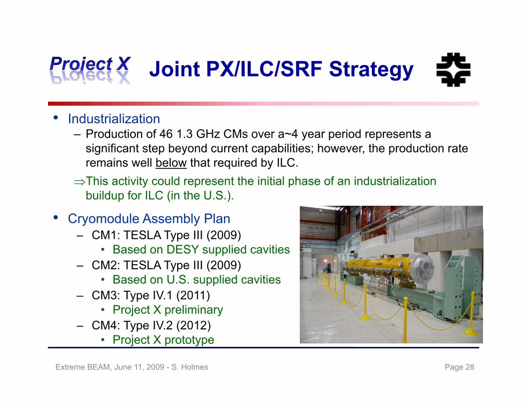
• Industrialization – Production of 46 1.3 GHz CMs over a~4 year period represents a
significant step beyond current capabilities; however, the production rate remains well below that required by ILC.Thi ti it ld t th i iti l h f i d t i li tiThis activity could represent the initial phase of an industrialization buildup for ILC (in the U.S.).
• Cryomodule Assembly Plan– CM1: TESLA Type III (2009)
• Based on DESY supplied cavities– CM2: TESLA Type III (2009)
• Based on U S supplied cavities• Based on U.S. supplied cavities– CM3: Type IV.1 (2011)
• Project X preliminary– CM4: Type IV.2 (2012)
• Project X prototype
Page 28Extreme BEAM, June 11, 2009 - S. Holmes
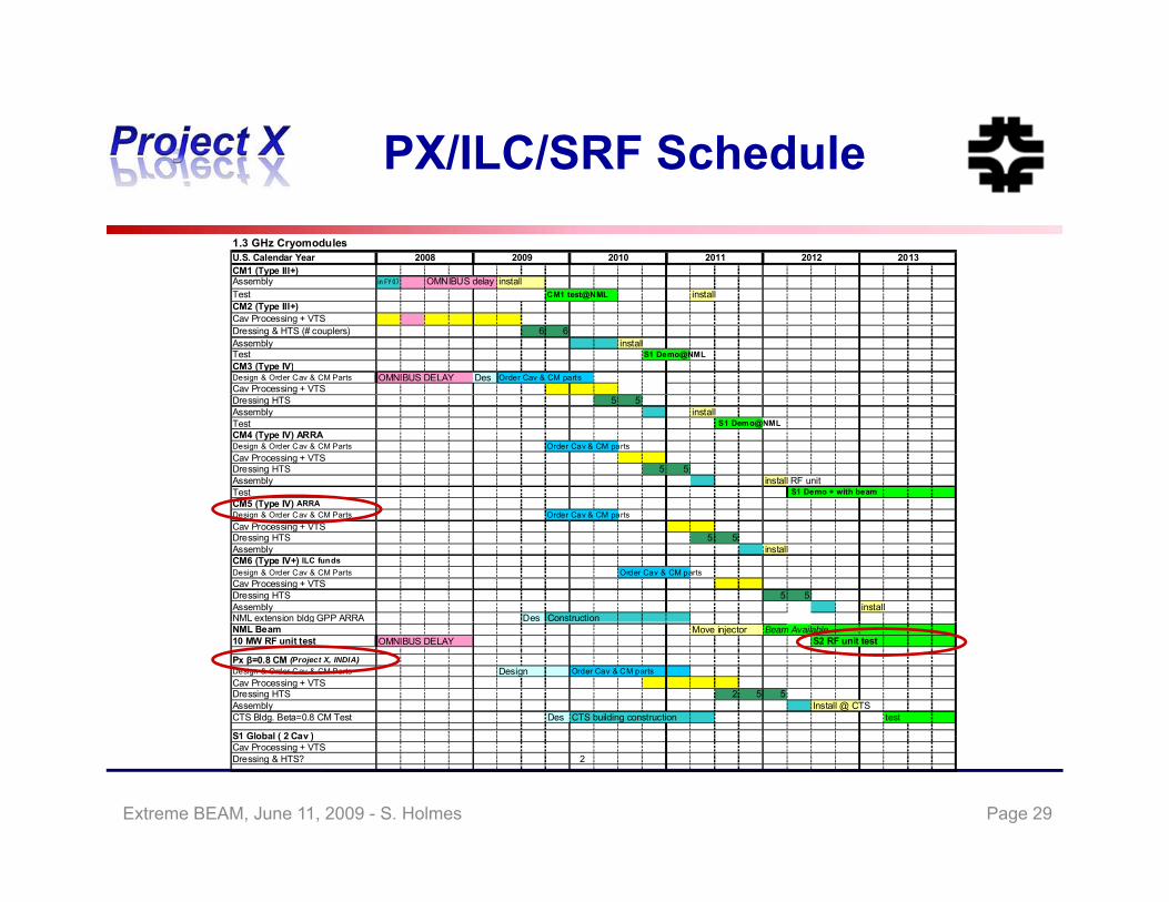
PX/ILC/SRF SchedulePX/ILC/SRF Schedule1.3 GHz CryomodulesU.S. Calendar YearCM1 (Type III+)Assembly in FY07 OMNIBUS delay install
2012 20132008 2009 2010 2011
Assembly in FY07 OMNIBUS delay installTest CM1 test@NML installCM2 (Type III+)Cav Processing + VTSDressing & HTS (# couplers) 6 6Assembly installTest S1 Demo@NMLCM3 (Type IV)Design & Order Cav & CM Parts OMNIBUS DELAY Des Order Cav & CM partsCav Processing + VTSDressing HTS 5 5Assembly installTest S1 Demo@NMLCM4 (Type IV) ARRADesign & Order Cav & CM Parts Order Cav & CM partsCav Processing + VTSDressing HTS 5 5Assembly install RF unitTest S1 Demo + with beamCM5 (Type IV) ARRA ( yp )Design & Order Cav & CM Parts Order Cav & CM partsCav Processing + VTSDressing HTS 5 5Assembly installCM6 (Type IV+) ILC fundsDesign & Order Cav & CM Parts Order Cav & CM partsCav Processing + VTSDressing HTS 5 5Assembly installNML extension bldg GPP ARRA Des ConstructiongNML Beam Move injector Beam Available10 MW RF unit test OMNIBUS DELAY S2 RF unit test
Px β=0.8 CM (Project X, INDIA)Design & Order Cav & CM Parts Design Order Cav & CM partsCav Processing + VTSDressing HTS 2 5 5Assembly Install @ CTSCTS Bldg. Beta=0.8 CM Test Des CTS building construction test
S1 Global ( 2 Cav )S1 Global ( 2 Cav )Cav Processing + VTSDressing & HTS? 2
Page 29Extreme BEAM, June 11, 2009 - S. Holmes

Joint PX/ILC StrategyJoint PX/ILC Strategy
• Other opportunities:– Linac beam dynamics– e-cloud studies and simulations, including participation in CESR_TA– RF power generation, distribution, controls, and diagnostics share many
f t ifeatures in common.– Conventional facilities designs provide opportunities for common
solutions.– ILCTA NML rf unit test will fulfill many of the requirements of S2 andILCTA_NML rf unit test will fulfill many of the requirements of S2, and
will be available for studies with both PX and ILC beam current parameters.
– Construction and operational experience with Project X will be invaluable in planning/executing ILC (if PX were to precede ILC, ditto for XFEL)
Essentially all these efforts are using shared (people) resources Essentially all these efforts are using shared (people) resources.
Page 30Extreme BEAM, June 11, 2009 - S. Holmes
Joint PX/NF/MC StrategyJoint PX/NF/MC Strategy
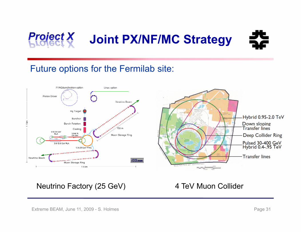
Future options for the Fermilab site:p
Neutrino Factory (25 GeV) 4 TeV Muon Collidery ( )
Page 31Extreme BEAM, June 11, 2009 - S. Holmes
Joint PX/NF/MC StrategyJoint PX/NF/MC Strategy
• Project X shares many features with the proton driver required for a Neutrino Factory or Muon Collider
– IDS-NF shows 4 MW @ 10 5 GeV proton energy– Muon Collider requires similar power, but requires charge consolidated
i t i l b hinto a single bunch– It is inevitable that a muon facility will require a ring(s) for accumulation
and/or beam compression between the linac and production target.
• Natural evolutionary schemes through neutrino superbeams:
NOA Very Long Baseline Neutrino Factory Muon Collider
• Close coordination with NFMCC MCTF and IDS NF• Close coordination with NFMCC, MCTF, and IDS_NF
Page 32Extreme BEAM, June 11, 2009 - S. Holmes
Joint PX/NF/MC StrategyJoint PX/NF/MC Strategy
• Develop upgrade concept for the Project X linac aimed at 2-4 MW – The ICD includes such a concept (up to 4 MW): rep rate x8
• Develop a performance specification for a Proton Driver supporting a Neutrino Factory and Muon Collider, consistent with Project XNeutrino Factory and Muon Collider, consistent with Project X concepts.
– Issues: Average beam power, repetition rate, particles/bunch, bunch intensity
– These issues will require a new storage ring(s) downstream of the linac.
• Develop a conceptual design for the NF/MC Proton Driver based on Project X linac and downstream accumulation/packaging ring(s).oject ac a d do st ea accu u at o /pac ag g g(s)
• Coordinate with NFMCC, MCTF, and IDS_NF
Page 33Extreme BEAM, June 11, 2009 - S. Holmes
Collaboration PlanCollaboration Plan
• A multi-institutional collaboration has been established to organize and execute the Project X RD&D Program.
– Organized as a “national project with international participation”.• Fermilab as lead laboratory
International participation via in kind contributions established• International participation via in-kind contributions, established through bi-lateral MOUs. (First MOU with India in place)
– Collaboration MOU for the RD&D phase outlines basic goals, and the means of organizing and executing the work. Signatories:g g g g
ANL ORNL/SNSBNL MSUCornell TJNAFFermilab SLACLBNL ILC/ART
– Collaborators to assume responsibility for components and sub-system design development cost estimating and potentially constructiondesign, development, cost estimating, and potentially construction .
Page 34Extreme BEAM, June 11, 2009 - S. Holmes
Alternative ConfigurationsAlternative Configurations
• Consideration of alternative designs is required by the DOE Project M t O dManagement Order.
• A primary consideration is the low energy program– The Recycler as utilized in the ICD has limitations in providing a flexible
source of useful beam to the low energy flavor program
• Primary alternatives we are looking at:– Linac operated in CW (1 mA) mode up to 2 GeVac ope ated C ( ) ode up to Ge– Rapid cycling synchrotron for acceleration from 2 GeV to 8 GeV “Mix and match” opportunities for the evaluation phase– Upgrade to NF/MC power capabilities requires more thinking
• Alternative configuration document under development (ACD V1.0)– Document, and associated cost estimate, to be prepared utilizing same
team, methodology, and design criteria as ICD, gy, g– Anticipate release late summer
Page 35Extreme BEAM, June 11, 2009 - S. Holmes

Alternative ConfigurationAlternative Configuration
Page 36Extreme BEAM, June 11, 2009 - S. Holmes
Alternative ConfigurationO ti S i
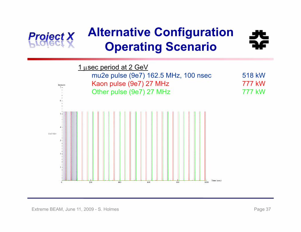
1 sec period at 2 GeV
Operating Scenario
mu2e pulse (9e7) 162.5 MHz, 100 nsec 518 kWKaon pulse (9e7) 27 MHz 777 kWOther pulse (9e7) 27 MHz 777 kW
Page 37Extreme BEAM, June 11, 2009 - S. Holmes

Alternative ConfigurationB S tBeam Spectra
Page 38Extreme BEAM, June 11, 2009 - S. Holmes

Working Timeline (t h i ll li it d)(technically limited)
• FY2009– Complete Initial Configuration Document (ICD)– Develop Upgrade Concept for 2-4 MW at 8 GeV– Form RD&D Collaboration
E bli h P j M– Establish Project Management team– Revise RD&D plan and initiate work– Complete a preliminary cost estimate based on the ICD
Complete Mission Needs Statement– Complete Mission Needs Statement– Receive CD-0– Request PED funds for FY2011– Initiate work on Conceptual Design Reportt ate o o Co ceptua es g epo t– Develop NEPA strategy
Page 39Extreme BEAM, June 11, 2009 - S. Holmes
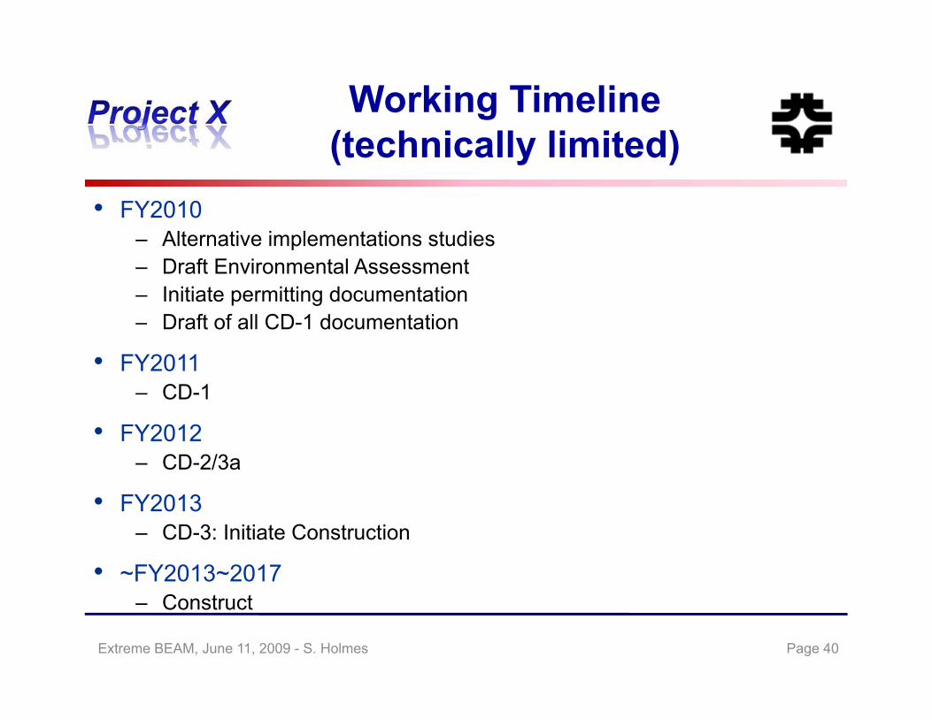
Working Timeline (t h i ll li it d)(technically limited)
• FY2010– Alternative implementations studies– Draft Environmental Assessment– Initiate permitting documentation
D f f ll CD 1 d i– Draft of all CD-1 documentation
• FY2011– CD-1
• FY2012– CD-2/3a
FY2013• FY2013– CD-3: Initiate Construction
• ~FY2013~2017– Construct
Page 40Extreme BEAM, June 11, 2009 - S. Holmes
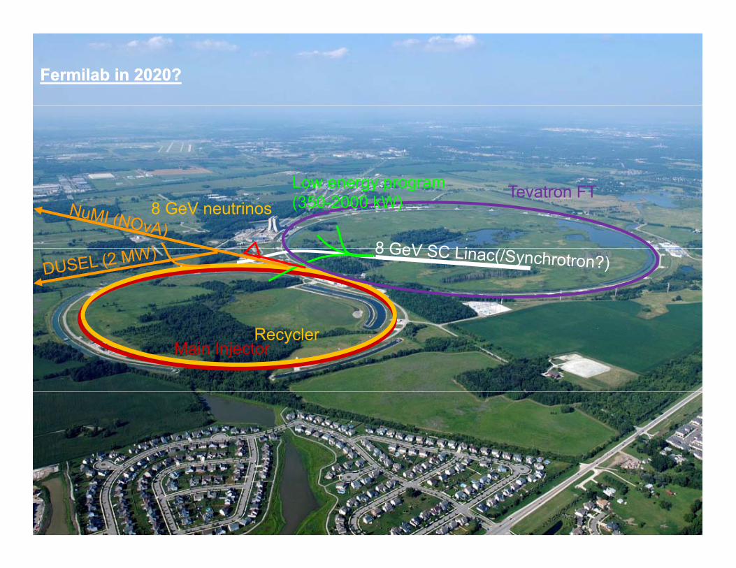
Fermilab in 2020?Fermilab in 2020?
L8 GeV neutrinos
Low energy program(350-2000 kW) Tevatron FT
Main InjectorRecycler
Young-Kee Kim: Ten Year Plan (Science and Resources), FRA VC Meeting 2009-04-09
41Young-Kee Kim Fermilab Strategic Plan Slide 41

8 GeV Superconducting LinacWith X-Ray FEL, 8 GeV Neutrino & Spallation Sources, LC and Neutrino Factory
SY-120Fixed-Target
Neutrino“Super-
NUMI Damping Ringsfor TESLA @ FNALWith 8 GeV e+ Preacc.
8 GeV LinacX-RAY FEL LAB
8 GeVneutrino
Anti-Proton
pBeams” Off-
Axis
~ 700m Active Length8 GeV Linacneutrino
Main BunchingInjector@2 MW
& Long-PulseNeutrino Target
Target and Muon Cooling Channel
gRing Recirculating
Linac for Neutrino Factory& Long Pulse
Spallation Source?
Neutrinos
Short Baseline Detector Array
VLHC at to “Homestake”
CFermilab
SummarySummary
• Project X is central to Fermilab’s strategy for future development of the accelerator complex:
– Energy Frontier: Aligned with ILC technology development; Fermilab as potential site for ILC or a Muon ColliderI t it F ti W ld l di i t i d– Intensity Frontier: World leading program in neutrinos and rare processes; Fermilab as potential Neutrino Factory site
• Initial configuration, and preliminary cost estimate, established– >2 MW at 60-120 GeV, simultaneous with >150 kW at 8 GeV– Upgradable to 2-4 MW at 8 GeV– Alternative configuration under development
• The facility could be constructed over the period ~2013 - 2017
• Integrated effort on Project X, ILC, and Muon Facilities
• Collaboration being formed
Page 43Extreme BEAM, June 11, 2009 - S. Holmes