project: tcw, patalganga tender ref. no. : bl/li/tcw...
TRANSCRIPT

Project: TCW, Patalganga Tender Ref. No. : BL/LI/TCW-MUM/ELECTRICAL/16-17/15
SBU: Logistics
1
Bidder Signature & Stamp
LOGISTICS INFRASTRUCTURE
Food Processing, Packaging and Temperature Controlled Warehouse Plot No. F-9/5, Additional MIDC Patalganga, District – Raigarh, Maharashtra
Tender for
Design, Supply, Fixing, Testing and Commissioning of H.T. & L.T. Electrical Works
,
TENDER NO: BL/LI/CC/TCW-MUM/ELECTRICAL/16-17/15 Date:- 24-12-2016 Due Date & Time:- 16-01-2017
Project: TCW, Patalganga Tender Ref. No. : BL/LI/TCW-MUM/ELECTRICAL/16-17/15
SBU: Logistics
2
Bidder Signature & Stamp
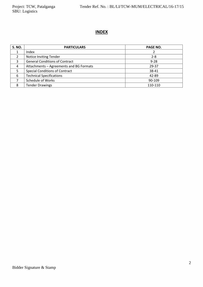
INDEX
S. NO. PARTICULARS PAGE NO.
1 Index 2
2 Notice Inviting Tender 2-8
3 General Conditions of Contract 9-28
4 Attachments – Agreements and BG Formats 29-37
5 Special Conditions of Contract 38-41
6 Technical Specifications 42-89
7 Schedule of Works 90-109
8 Tender Drawings 110-110

Project: TCW, Patalganga Tender Ref. No. : BL/LI/TCW-MUM/ELECTRICAL/16-17/15
SBU: Logistics
3
Bidder Signature & Stamp
NOTICE INVITING TENDER Balmer Lawrie & Co Ltd invite ONLINE BIDS from experienced, competent and resourceful contractors with sound technical and financial capabilities for Design, Supply, Fixing, Testing and Commissioning of H.T. & L.T. Electrical Works for Food Processing, Packaging and Temperature Controlled Warehouse at Patalganga, in Raigad District, Maharashtra. Tenderers are advised to download Notice Inviting Tender along with other tender documents from www.balmerlawrie.com. TENDER SCHEDULE
S. No Description Details
1 Name of Work Design, Supply, Fixing, Testing and commissioning of H.T. & L.T. Electrical Works.
2 Tender No BL/LI/CC/TCW-MUM/ELECTRICAL/16-17/15
3 Completion Period Total Completion shall be 15 Weeks (7 Days Per Week) from the date of receipt of PO or LOI whichever is earlier.
4 Validity Of Offer 120 days from the due date of tender submission.
5 Tender Fee Rs. 2000/-
6 EMD Rs. 90,000/-
7 Pre-bid Meeting 04.01.2017
8 Downloading / Submission of Tender :
a. Starts on 24.12.2016
b. Closes on 16.01.2016 at 17.30 Hrs.
SPECIAL INSTRUCTION TO BIDDER
1. LIST OF DOCUMENTS TO BE SUBMITTED
I. The signed and stamped copies of following documents should be sent as part of the technical/commercial bid submission i. Power of Attorney authorizing the person who has signed the tender to act and sign on behalf
of the company. ii. Certificate of registration/incorporation in the case of Pvt Ltd/Public Ltd Company /certified
copy of / partnership deed in the case of LLP/Partnership firm/ any document under the relevant rules/laws if the firm is a proprietorship firm.
iii. Copy of Income Tax PAN Card. iv. Copies of VAT, Excise and Service Tax Registration number. v. Charted accountant’s certificate or Audited / Certified Balance sheet and Profit and Loss account
of tenderer’s company for last three years ending 31.03.15 or 31.03.16 as the case may. vi. Copies of valid PF and ESI Registration.
vii. Copies of experience certificate as per Prequalification criteria mentioned in clause no 6 viii. The details as asked in the clause no. 25 of Technical Specification.
II. Tender Fee - Tender fee of Rs.2000/- (non-refundable) by demand draft on any Scheduled Bank
payable at Kolkata in favour of M/s Balmer Lawrie & Co. Ltd.
III. Earnest Money Deposit - EMD (Earnest Money Deposit) should be a Bank Draft or Bank Guarantee of Rs 90,000.00 (Rupees Ninety Thousand only) drawn in favour of Balmer Lawrie & Co Ltd payable at Kolkata or executed by a scheduled bank in favour of Balmer Lawrie & co Ltd as per format enclosed (in the case of a BG). EMD submitted by way of Bank Guarantee should be valid for a minimum period of 120 days from the due date of tender submission.

Project: TCW, Patalganga Tender Ref. No. : BL/LI/TCW-MUM/ELECTRICAL/16-17/15
SBU: Logistics
4
Bidder Signature & Stamp
Earnest Money deposit (EMD) and Tender Fee are exempted for vendors registered under NSIC or coming under the definition of Micro and Small Industries and holding valid registration certificates covering the tendered items/services.
2. VERIFICATION OF DOCUMENTS / SUBMISSION OF BIDS / CANCELLATION OF BIDS
a. If Balmer Lawrie wants to verify all the submitted documents, then the bidder should bring all original documents.
b. Failure on part of the tenderer to report on specified date and time for paper verification may result in rejection of the tender submitted by them without further communication.
c. Tenderer should be in a position to produce all the original documents and/or any other information on dates as intimated or as and when required by Balmer Lawrie.
d. Incomplete Tenders are liable for rejection without any reference to the tenderer and decision of Balmer Lawrie in this respect will be final.
e. If at any stage it transpires that any bidder has submitted false or forged documents, then the bidder may be Blacklisted and the EMD would be forfeited, contract could be cancelled, criminal prosecution or any other action as deemed fit may be initiated.
f. Balmer Lawrie reserves the right to reject any or all tenders without assigning any reasons whatsoever.
g. Bids of any tenderer may be rejected if a conflict of interest between the bidder and Company (Balmer Lawrie) is detected at any stage.
h. All the bids will be evaluated based on the criteria as mentioned in this NIT. Tenders of those bidders who are not meeting the criteria as specified in the NIT, will not be considered for commercial evaluation.
i. Tenders, if submitted through e-mail or fax, shall be summarily rejected.
3. SCOPE OF WORK
a. Design, Supply, Fixing, Testing and Commissioning of electrical equipment and accessories mentioned as
here under and the attached Bill of Quantities for the various items described therein. This also covers
the procedure to be adopted for Inspection, Testing and Commissioning for all electrical equipment at
site. The works shall be carried out strictly in accordance to the Tender conditions. The Electrical
contractor shall be well established and must be a reputed Electrical Contractor having License for
working as electrical contractor of either 22KV/ 11KV/ 415 Volts substations issued by state
administrations of the state in which the contractor is working.
b. Supply, installation, testing and commissioning of the followings
(i) Metering Kiosk as per the approving electrical department.
(ii) HT Panels, HT Breakers etc. complete
(iii) Transformers
(iv) L.T. Panels & Accessories,
(v) 11 KV-E-Grade XLPE HT Cable as per MSEDCL Specifications
(vi) Earthings
(vii) External Street Lightings
(viii) Internal Lighting System
(ix) UPS
c. Obtaining pre and post approval from the all Electrical Departments including Electrical Inspectorate, the
necessary official charges pertaining to the approval shall be borne by BL however any other charges
shall be to the contractors account.
Project: TCW, Patalganga Tender Ref. No. : BL/LI/TCW-MUM/ELECTRICAL/16-17/15
SBU: Logistics
5
Bidder Signature & Stamp
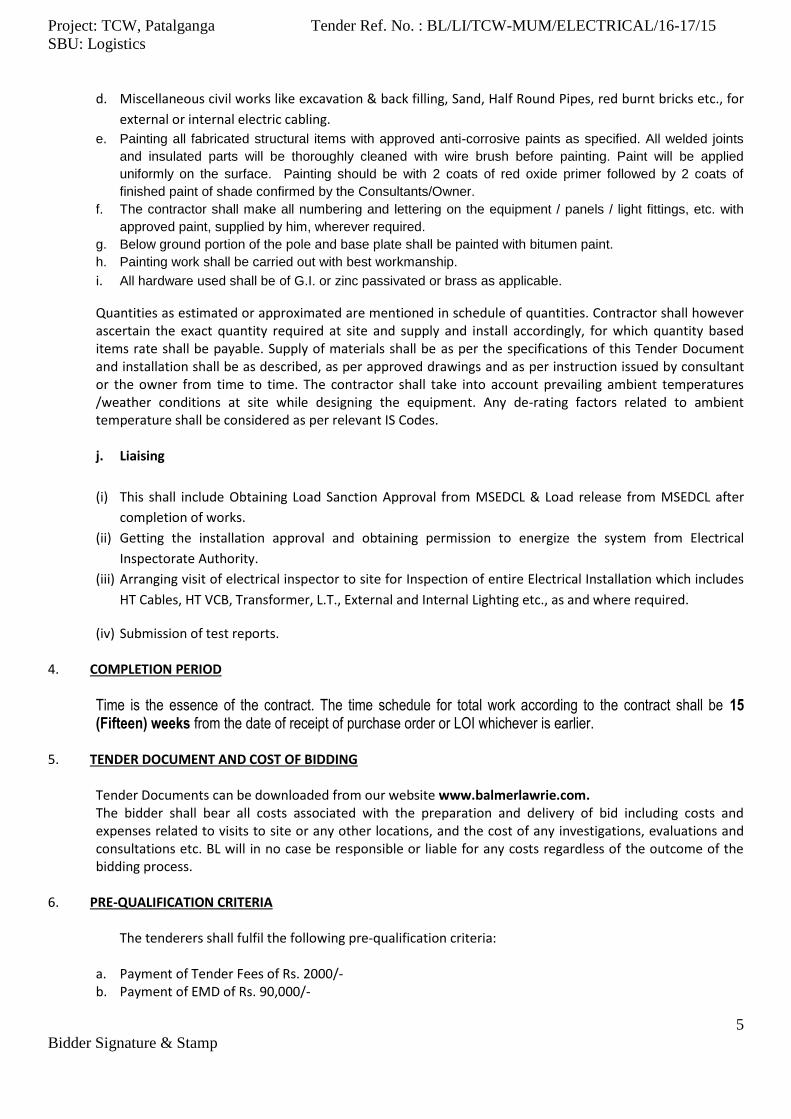
d. Miscellaneous civil works like excavation & back filling, Sand, Half Round Pipes, red burnt bricks etc., for
external or internal electric cabling.
e. Painting all fabricated structural items with approved anti-corrosive paints as specified. All welded joints
and insulated parts will be thoroughly cleaned with wire brush before painting. Paint will be applied
uniformly on the surface. Painting should be with 2 coats of red oxide primer followed by 2 coats of
finished paint of shade confirmed by the Consultants/Owner.
f. The contractor shall make all numbering and lettering on the equipment / panels / light fittings, etc. with
approved paint, supplied by him, wherever required.
g. Below ground portion of the pole and base plate shall be painted with bitumen paint.
h. Painting work shall be carried out with best workmanship.
i. All hardware used shall be of G.I. or zinc passivated or brass as applicable.
Quantities as estimated or approximated are mentioned in schedule of quantities. Contractor shall however ascertain the exact quantity required at site and supply and install accordingly, for which quantity based items rate shall be payable. Supply of materials shall be as per the specifications of this Tender Document and installation shall be as described, as per approved drawings and as per instruction issued by consultant or the owner from time to time. The contractor shall take into account prevailing ambient temperatures /weather conditions at site while designing the equipment. Any de-rating factors related to ambient temperature shall be considered as per relevant IS Codes. j. Liaising
(i) This shall include Obtaining Load Sanction Approval from MSEDCL & Load release from MSEDCL after
completion of works.
(ii) Getting the installation approval and obtaining permission to energize the system from Electrical
Inspectorate Authority.
(iii) Arranging visit of electrical inspector to site for Inspection of entire Electrical Installation which includes
HT Cables, HT VCB, Transformer, L.T., External and Internal Lighting etc., as and where required.
(iv) Submission of test reports. 4. COMPLETION PERIOD
Time is the essence of the contract. The time schedule for total work according to the contract shall be 15 (Fifteen) weeks from the date of receipt of purchase order or LOI whichever is earlier.
5. TENDER DOCUMENT AND COST OF BIDDING
Tender Documents can be downloaded from our website www.balmerlawrie.com. The bidder shall bear all costs associated with the preparation and delivery of bid including costs and expenses related to visits to site or any other locations, and the cost of any investigations, evaluations and consultations etc. BL will in no case be responsible or liable for any costs regardless of the outcome of the bidding process.
6. PRE-QUALIFICATION CRITERIA
The tenderers shall fulfil the following pre-qualification criteria:
a. Payment of Tender Fees of Rs. 2000/- b. Payment of EMD of Rs. 90,000/-
Project: TCW, Patalganga Tender Ref. No. : BL/LI/TCW-MUM/ELECTRICAL/16-17/15
SBU: Logistics
6
Bidder Signature & Stamp
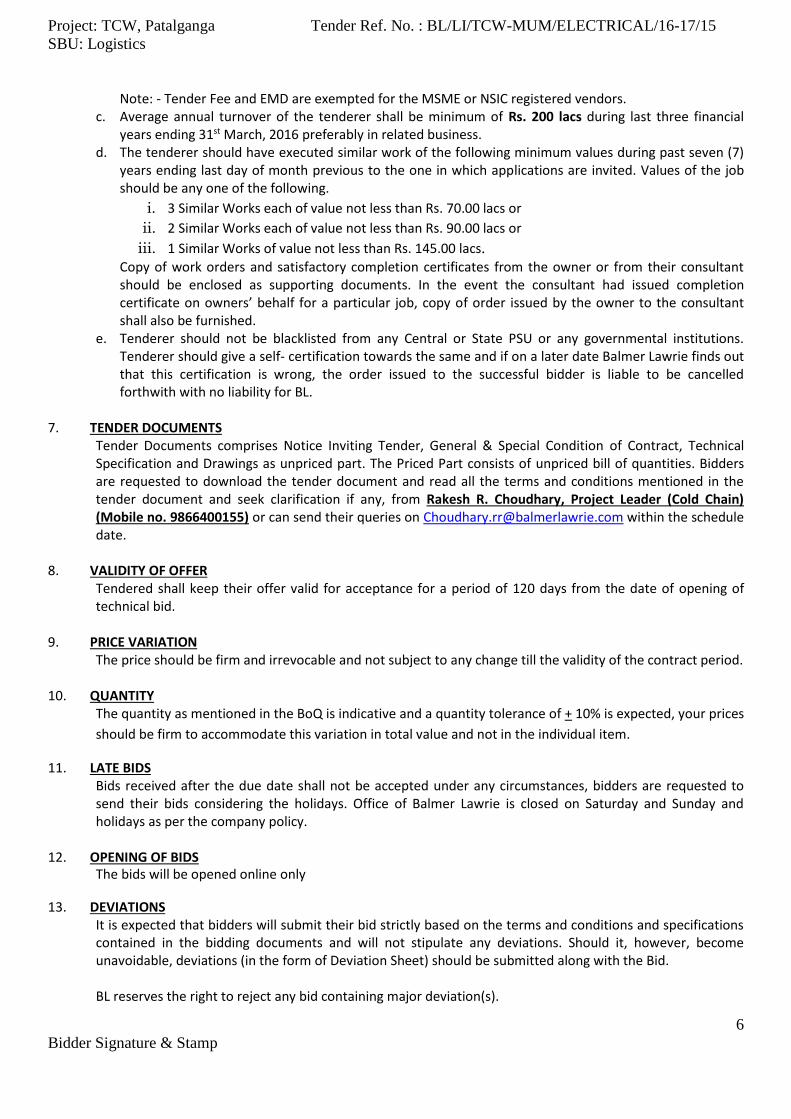
Note: - Tender Fee and EMD are exempted for the MSME or NSIC registered vendors. c. Average annual turnover of the tenderer shall be minimum of Rs. 200 lacs during last three financial
years ending 31st March, 2016 preferably in related business. d. The tenderer should have executed similar work of the following minimum values during past seven (7)
years ending last day of month previous to the one in which applications are invited. Values of the job should be any one of the following.
i. 3 Similar Works each of value not less than Rs. 70.00 lacs or ii. 2 Similar Works each of value not less than Rs. 90.00 lacs or
iii. 1 Similar Works of value not less than Rs. 145.00 lacs. Copy of work orders and satisfactory completion certificates from the owner or from their consultant should be enclosed as supporting documents. In the event the consultant had issued completion certificate on owners’ behalf for a particular job, copy of order issued by the owner to the consultant shall also be furnished.
e. Tenderer should not be blacklisted from any Central or State PSU or any governmental institutions. Tenderer should give a self- certification towards the same and if on a later date Balmer Lawrie finds out that this certification is wrong, the order issued to the successful bidder is liable to be cancelled forthwith with no liability for BL.
7. TENDER DOCUMENTS
Tender Documents comprises Notice Inviting Tender, General & Special Condition of Contract, Technical Specification and Drawings as unpriced part. The Priced Part consists of unpriced bill of quantities. Bidders are requested to download the tender document and read all the terms and conditions mentioned in the tender document and seek clarification if any, from Rakesh R. Choudhary, Project Leader (Cold Chain) (Mobile no. 9866400155) or can send their queries on [email protected] within the schedule date.
8. VALIDITY OF OFFER
Tendered shall keep their offer valid for acceptance for a period of 120 days from the date of opening of technical bid.
9. PRICE VARIATION The price should be firm and irrevocable and not subject to any change till the validity of the contract period.
10. QUANTITY
The quantity as mentioned in the BoQ is indicative and a quantity tolerance of + 10% is expected, your prices
should be firm to accommodate this variation in total value and not in the individual item.
11. LATE BIDS Bids received after the due date shall not be accepted under any circumstances, bidders are requested to send their bids considering the holidays. Office of Balmer Lawrie is closed on Saturday and Sunday and holidays as per the company policy.
12. OPENING OF BIDS
The bids will be opened online only
13. DEVIATIONS It is expected that bidders will submit their bid strictly based on the terms and conditions and specifications contained in the bidding documents and will not stipulate any deviations. Should it, however, become unavoidable, deviations (in the form of Deviation Sheet) should be submitted along with the Bid.
BL reserves the right to reject any bid containing major deviation(s).

Project: TCW, Patalganga Tender Ref. No. : BL/LI/TCW-MUM/ELECTRICAL/16-17/15
SBU: Logistics
7
Bidder Signature & Stamp
14. BID SIGNING All signatures in bids shall be dated and shall bear a seal/stamp of the bidder. In addition, all pages of the bids before submission of the bid shall be initiated at lower right hand corner by the Bidder or by a person holding a Power of Attorney or a letter of authorization authorizing him to sign on behalf of the bidder.
15. TENDER SUBMISSION
The bidders would be required to register on the e-procurement site https://balmerlawrie.eproc.in and submit their Tenders online. For registration and online Tender submission bidder may contact the following officials at the HELP DESK of M/s C1 India on browsing to the website https://balmerlawrie.eproc.in during business hours (10:00 a.m. to 06:30 p.m.) from Monday to Friday (Excluding holidays of the Company):
Sl. No. Name e-mail ID Contact No.
1. Tuhin Ghosh [email protected] +91-8981165071
2. Tirtha Das [email protected] +91-9163254290
3. Ravi Gaiwal [email protected] +91-022-66865633
4. Ujjal Mitra [email protected] +91-89866 78058
5. Rajesh Kumar [email protected] +91-96504 65143
The bidder shall authenticate the Bid with his Digital Certificate for submitting the Tender electronically on e-procurement platform and the Tenders not authenticated by digital certificate of the bidder will not be accepted on the e-procurement platform.
All the bidders who do not have digital certificates need to obtain Digital Certificate (with both Signing and Encryption Components). They may contact help desk of M/s C1 India.
The bidder shall invariably furnish the original DD towards Tender fee and DD/BG towards EMD to the tender inviting authority so as to reach on or before the due date and time of the Tender either personally or through courier or by post and the receipt of the same within the stipulated time shall be the responsibility of bidder. The Company shall not take any responsibility for any delay or non-receipt. If any of the documents furnished by the bidder is found to be false/fabricated/bogus, the bidder is liable for black listing, forfeiture of the EMD, cancellation of work and criminal prosecution.
The bidder has to keep track of any changes by viewing the Addendum / Corrigenda issued by the Tender Inviting Authority on time-to-time basis in the e-Procurement platform. Only at the time of inviting offers, there will be a paper ad. There will be no further paper advertisement on this. Interested parties have to keep referring to the website for further information. The Company calling for tenders shall not be responsible for any claims/problems arising out of this.
For Price Bid submissions, the bidders are requested to download the Price Bid Format which is in Excel Sheet, fill in all the relevant details and upload the same after signing and stamping. The bidder should complete all the processes and steps required for bid submission. The successful Tender submission can be ascertained once acknowledgement is given by the system through Tender submission number after completing all the process and steps. M/s C1 India or Balmer Lawrie will not be responsible for incomplete Tender submission by users. Bidders may also note that the incomplete Tenders will not be saved by the system and are not available for the Tender Inviting Authority for processing.
The Company (Balmer Lawrie & Co. Ltd.) nor the service provider (M/s C1 India) is responsible for any failure or non-submission of Tenders due to failure of internet or other connectivity problems or reasons thereof.
Project: TCW, Patalganga Tender Ref. No. : BL/LI/TCW-MUM/ELECTRICAL/16-17/15
SBU: Logistics
8
Bidder Signature & Stamp
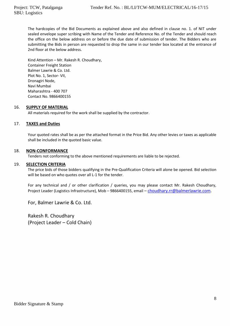
The hardcopies of the Bid Documents as explained above and also defined in clause no. 1. of NIT under sealed envelope super scribing with Name of the Tender and Reference No. of the Tender and should reach the office on the below address on or before the due date of submission of tender. The Bidders who are submitting the Bids in person are requested to drop the same in our tender box located at the entrance of 2nd floor at the below address.
Kind Attention – Mr. Rakesh R. Choudhary, Container Freight Station Balmer Lawrie & Co. Ltd. Plot No. 1, Sector- VII, Dronagiri Node, Navi Mumbai Maharashtra - 400 707
Contact No. 9866400155
16. SUPPLY OF MATERIAL All materials required for the work shall be supplied by the contractor.
17. TAXES and Duties Your quoted rates shall be as per the attached format in the Price Bid. Any other levies or taxes as applicable shall be included in the quoted basic value.
18. NON-CONFORMANCE Tenders not conforming to the above mentioned requirements are liable to be rejected.
19. SELECTION CRITERIA The price bids of those bidders qualifying in the Pre-Qualification Criteria will alone be opened. Bid selection will be based on who quotes over all L-1 for the tender.
For any technical and / or other clarification / queries, you may please contact Mr. Rakesh Choudhary,
Project Leader (Logistics Infrastructure), Mob – 9866400155, email – [email protected].
For, Balmer Lawrie & Co. Ltd.
Rakesh R. Choudhary (Project Leader – Cold Chain)

Project: TCW, Patalganga Tender Ref. No. : BL/LI/TCW-MUM/ELECTRICAL/16-17/15
SBU: Logistics
9
Bidder Signature & Stamp
GENERAL CONDITIONS OF CONTRACT
1 DEFINITIONS 1.00 GENERAL The following expressions hereunder and elsewhere in the contract documents used shall have the following
meanings hereunder respectively assigned to them except where the context otherwise requires: 1.01 The "Owner / "Employer" shall mean M/s Balmer Lawrie & Co. Ltd., a company incorporated in India and
having its registered office at 21, Netaji Subhas Road, Kolkata - 700 001 and shall include its successors and assigns.
1.02 "Tenderers" or "Bidders" shall mean such parties who have been issued Tender Document by the Owner and
those parties who have submitted these offers to the Owner in response to the Tender Document issued to them.
1.03 "Tender Document" shall mean the Tender Documents comprising Part I (Un-priced Bid) –Notice inviting
tender, General Conditions of contract, Special Conditions of Contract, Technical Specification, Bill of Quantities, Drawings / Sketches, Data Sheets, Addenda / Corrigenda to the tender document issued by the Owner, Form of Tender and Part II (Priced Bid) – Un Price BOQ.
1.04 The "Contractor / Successful tenderer" shall mean the tenderer selected by the Owner for the performance
of the work and shall include the successors and Owner permitted assigns of the Contractor. 1.05 The "Sub-contractor" shall mean any person or firm or company (other than the Contractor) to whom any
part of work has been entrusted by the Contractor with the written consent of the Engineer-in-Charge, and the legal representatives, Successors and permitted assigns of such person, firm or company.
1.06 The "Project" shall mean Design, Supply, Fixing, Testing and Commissioning of H.T. & L.T. Electrical Works
for Food Processing, Packaging and Temperature Controlled Warehouse at Patalganga, in Raigad District, Maharashtra.
1.07 The "Project Manager" shall mean the Officer nominated by Owner to co-ordinate and supervise all the
activities connected with the implementation of project on their behalf. "Project Manager" may at his discretion depute Owner's officers to co-ordinate / supervise the work of Contractor / Consultants at site.
1.08 The "Engineer-in-Charge" shall mean the Engineer/Agency authorized by the Owner for the purpose of the
Contract for overall supervision and co-ordination of site activity and certification of billing. 1.09 "Site" shall mean all such land, waters and other places on, under, in or through which the works for the
Project are to be performed under the Contract. 1.10 The "Site Engineer" shall mean the Engineer(s) for the time being deputed by the Engineer-in-Charge as Site
Engineer for the work to be performed by the Contractor at any and/or all job sites and to coordinate all activities of all parties at site.
1.11 "Inspecting Authority" means Third Party Inspection Agency (TPIA) as specified by the Owner/Consultant or
Owner's authorized representative or Consultant's representative.
Project: TCW, Patalganga Tender Ref. No. : BL/LI/TCW-MUM/ELECTRICAL/16-17/15
SBU: Logistics
10
Bidder Signature & Stamp
1.12 The "Work" and "Scope of Work" shall mean the totality of the work by expression or implication envisaged in the contract and shall include all material, equipment and labour required for or relative or incidental to or in connection with the commencement, performance or completion of any work and/or for incorporation in the work.
1.13 The "Works" shall mean the product(s) of the work and shall include all extras, additions, alterations or
substitution as required for the purpose of the contract. 1.14 The "Works Contract" or "Contract" shall mean the totality of the agreements between the parties as
derived from the Contract Documents for the entire work. 1.15 The "Contract Documents" shall mean collectively Tender Documents and the Contract Documents as laid
out in the Owner's Standard Contract Format which is based on the General & Special Conditions of Contract.
1.16 The "Specification(s)" shall mean the various specifications as set out in the specifications forming part of the
tender documents and as referred to and derived from the contract and any order(s) or instruction(s) thereunder, and the absence of any specifications as aforesaid covering any particular work or part of portion thereof, shall mean the relevant Indian Standard Institution Specifications for or relative to the particular work or part thereof, and in the absence of any Indian Standard Institution Specifications covering the relative work or part or portion thereof, shall mean the standards or specifications of any other country applied in India as a matter of standard engineering practice and approved in writing by the Engineer-in-Charge or Site Engineer with or without modifications.
1.17 "Order" and "Instruction" shall respectively mean any written Order or Instruction given by the Engineer-in-
Charge or Site Engineer within the scope of their respective powers in terms of the Contract and shall include alteration / variation order to effect additions to or deletion from and / or alteration in the work detailed in the contract.
1.18 "Plans" and "Drawings" shall mean maps, plans, drawings, sketches, tracings and prints forming part of the
tender documents and any details or working drawings, amendments and/or modifications thereof approved in writing by the Engineer-in-Charge, Site Engineer or any agency notified by the Engineer-in-Charge to the Contractor for the purpose and shall include any other drawings or plans in connection with the work as may from time to time be furnished by or approved in writing by the Engineer-in-Charge or Site Engineer or any other agency nominated by the Engineer-in-Charge on his behalf in connection with the work.
1.19 "Temporary Work" / "Enabling Work" shall mean all such works which are required in or about the
execution, completion or maintenance of the work and if not provided for specifically in the Bill of Quantities shall be deemed to be done by the Contractor at his own cost in fulfilment of the contract.
1.20 "Constructional Plant" shall mean all such Plant & Machineries, appliances, aids or things of whatsoever
nature other than materials intended to form part of the permanent works which are required in or about the execution, completion for maintenance of temporary and permanent work.
1.21 "Completion Certificate" shall mean the Certificate to be issued by the Engineer-in-Charge after the work has
been completed to his satisfaction. 1.22 "The Final Certificate" in relation to the work shall mean the certificate to be issued after the period of
liability is over by the Owner regarding satisfactory compliance of various provisions of the contract by the contractor.

Project: TCW, Patalganga Tender Ref. No. : BL/LI/TCW-MUM/ELECTRICAL/16-17/15
SBU: Logistics
11
Bidder Signature & Stamp
1.23 "Period of Liability" or "Defect Liability Period" refers to the Specified period from the date of completion of
the entire work as indicated in the completion certificate up to the date of issue of Final Certificate during which the contractor is responsible for rectifying all defects "free of cost" to the satisfaction of Owner.
1.24 "Running Account Bill" shall mean a Bill for the payment of "On Account" to the Contractor. 1.26 "Agreed Variation" shall mean the statement of Agreed Variation annexed to the Acceptance of Tender or a
further Amendment to the Contract forming part thereof. 1.27 "Acceptance of Tender" shall mean the Acceptance of Tender issued by the Owner to the Contractor. 1.28 The "Total Contract Value" means the value of original work order issued and duly accepted by the
Contractor. The remuneration due to the Contractor in terms of the Contract on successful completion of the work shall mean the value of job actually executed by the Contractor within the original time schedule or within the approved extended time.
1.29 "Written Notice" or "Notice" in writing shall mean all hand written, typed / printed /email form sent (unless
delivered personally) or proved to have been received by registered post to the last known address / private / business or registered office, of the contractor and shall be deemed to have been received in the ordinary course of post it would have been delivered.
1.30 "Letter of Intent" shall mean intimation by a letter to the successful tenderer that the tender has been
accepted in accordance with the provisions contained therein. 1.31 "Progress Schedule" shall mean the time schedule of Progress of Work. 1.32 The "Alteration Order or Variation Order" means Order given in writing by the Owner to effect additions to
or deletions from and alterations in the work. 1.33 "Measurement book(s) / Sheet(s)" shall mean the register preserved by the Engineer-in-Charge, where all
measurements taken at site are neatly recorded by the Engineer-in-Charge or his authorized representative and signed in token of acceptance by the Contractor or his authorized representative.
2.00 DISCREPANCY IN TENDER DOCUMENT
Should there be any discrepancy, inconsistency, error or omission in the Tender Documents, the Tenderer shall bring it to the notice of the Owner / Engineer-in-Charge for necessary clarification / action. In the event such matters are referred to later the decision of the Owner / Engineer-in-Charge directing the manner in which the work is to be carried out shall be final & conclusive and the contractor shall carry out work in accordance with this decision.
3.00 NON-TRANSFERABILITY OF TENDER DOCUMENTS
Tender documents shall remain the property of the Owner and if obtained by one intending tenderer, shall not be utilizable by another without the consent of the Owner.
4.00 TENDERERS RESPONSIBILITY TO COLLECT ALL REQUIRED DATA (i) The tenderer should study all tender documents, carefully, understand the condition / drawing
Specification etc. before quoting. If there are any doubts about tender conditions he should obtain clarification from Rakesh R Choudhary (mob no. 9866400155), e-mail: [email protected]). This shall not be the justification for late submission or time extension for due date of submission of tender.

Project: TCW, Patalganga Tender Ref. No. : BL/LI/TCW-MUM/ELECTRICAL/16-17/15
SBU: Logistics
12
Bidder Signature & Stamp
All tender documents shall govern the contract, shall form part of the contract and shall be binding during the execution till completion of work.
(ii) The tenderer should visit the site and acquaint himself with the site conditions, all factors which are likely to be relevant for the works, availability and rates for various things including construction materials as per specification, shelter for staff etc. since these are to be provided / arranged by the tenderer (unless otherwise specified) at his own cost. In any case it will be deemed that tenderer has gone through the requirement and no claim whatsoever will be entertained on the plea of ignorance of factor or difficulties involved in fulfilling the tender conditions.
(iii) Under no circumstances, Tenders may be withdrawn or modified after its submission to the Owner. Negligence on the part of the Tenderer in preparing his tender confers no right for withdrawal or modification of his tender after the tender has been opened.
5.00 COMPLETE & COMPETITIVE OFFER (i) Tenderers are required to make the lowest offer for the work as per the enclosed specification and details
available therein. The estimated quantities given in the Bill of Quantities are approximate. As the work progresses, it is possible that there are variations & omission of items
(ii) The rates quoted should be inclusive of all materials, labour, incidental expenses, Equipment, Tools/Tackles,
Transportation of materials and Labour and taxes as defined in clause no. 17 of Notice Inviting Tenders. All materials are to be supplied by the Tenderer unless otherwise stated.
(iii) Incomplete / Conditional tender quotation or tenders those received late and / or not conforming to the
terms and conditions in the tender document will be liable to get rejected. (iv) It is in the Tenderer's interest to adhere to the Owner's tender conditions, specifications and Tender
Schedule. Should the tenderer however consider it unavoidable, deviations should be clearly spelt out with reference to tender conditions. Owner reserves the right to determine / evaluate financial implication of such deviations without any reference to the tenderer or at his discretion consider such tenders liable for disqualification.
(v) After "Unpriced" bids are evaluated, tenderers whose bids are found acceptable may be invited for
discussions for exchange of clarifications, required, if any. At that stage, depending on the merits of the case, opportunity may be given to amend the "Priced" bids already received along with the un-priced bids, but not opened until then. Such amendments or revisions would need to be submitted online only as per the given time frame. Tenders indicating counter proposals or deviations are liable to be rejected.
(vi) Tenderers are expected to quote rate for each item after careful analysis of cost involved for the
performance of the completed item considering all Specifications and Conditions of Contract. This will avoid loss of profit or gain in case of quantity variation or deletion of any item during the execution period. In case it is noticed that the rates quoted by the Tenderer for any item are unusually high or unusually low it will be sufficient cause for the rejection of the Tender unless the Owner is convinced about the reasonableness of the rates on scrutiny of the analysis for such rate to be furnished by the Tenderer on demand.
6.00 CONTRACT AGREEMENT The successful tenderer shall within 10 days of the Owner's communication to him of the Acceptance of the
Tender, execute formal agreement with the Owner in the pro-forma attached to the Tender Document.
Project: TCW, Patalganga Tender Ref. No. : BL/LI/TCW-MUM/ELECTRICAL/16-17/15
SBU: Logistics
13
Bidder Signature & Stamp
In the event of failure on the part of the successful tenderer to sign the agreement within the stipulated time period, the Earnest Money Deposit will be forfeited and the Acceptance of the Tender shall be considered as
cancelled.
7.00 EARNEST MONEY DEPOSIT (i) Tenderer shall be required to submit an Earnest Money of specified value as mentioned in NIT along with
the un-priced part of the tender and the same shall be returned to the unsuccessful tenderers after acceptance of order by the successful tenderer. Earnest money of successful bidder shall be released after submission of initial security deposit by them
The permissible forms of deposit are:
a) Bank draft drawn on a Kolkata branch of any Scheduled Bank in favour of Balmer Lawrie & Co. Ltd.
b) Bank Guarantee executed by any Schedule Bank as per proforma enclosed and shall be valid for a minimum period of 120 days after the due date of tender submission.
(ii) If the successful tenderer is unable to accept or execute orders when placed upon him or fails to deposit the
Initial Security Deposit or withdraws / revises his quoted prices and quantities offered, within the validity period of his tender or after placement of the Order / Letter of Acceptance, his Earnest Money Deposit shall be forfeited.
(iii) No interest is payable against Earnest Money Deposit.
8.00 SECURITY DEPOSIT (i) On acceptance of the Bid, Contractor shall within fifteen (15) days, deposit with Owner an Initial Security
Deposit of 5% of the Contract value and the same shall be in any of the following form:
a) Bank draft drawn on a Kolkata Branch of any Scheduled Bank in favour of Balmer Lawrie & Co Ltd.
b) Bank Guarantee executed by any Scheduled Bank as per proforma enclosed and shall be valid at least sixty days after the completion of work.
(ii) If Contractor fails to provide the Security Deposit within the period specified, such failure will constitute a
breach of the Contract and Owner shall be entitled to award the Work elsewhere at Contractor's risk and cost. The EMD of the bidder to whom Contract was awarded, shall be forfeited
(iii) No interest shall be payable against Security Deposit. (iv) As and by way of additional security, from every progress bill of Contractor, Security Deposit in the form of
Retention Money (interest free) at the rate of 10% of the Gross value of such bill as determined before payment shall be retained by the Owner. Owner can permit Contractor to replace the Security Deposit / Retention Money so retained by Bank Guarantee at his discretion after successful completion of the work.
(v) Wherever the Security Deposit / Retention Money is furnished by Contractor in any form other than
in cash or Demand Draft, Contractor shall be entirely responsible to keep such form of security deposit enforceable by extending the validity thereof before one month of date of expiry and keep them enforceable, until released by Owner after the Defect Liability Period.
Project: TCW, Patalganga Tender Ref. No. : BL/LI/TCW-MUM/ELECTRICAL/16-17/15
SBU: Logistics
14
Bidder Signature & Stamp
(vi) The Security Deposit / Retention Money shall remain at the entire disposal of Owner as a security for satisfactory execution and completion of the Work(s). Owner shall be at liberty to deduct and appropriate from the Security Deposit / Retention Money such damages (liquidated or otherwise) and other dues and recoveries from Contractor under this Contract and the amount by which Security Deposit / Retention Money is reduced by such appropriations, will be made by further deductions from Contractor's subsequent bills to that extent as to make up the Security Deposit / Retention Money.
(vii) Notwithstanding anything to contrary, in as much as the Security Deposit is to be in cash with Owner, Owner
shall be entitled to enforce any of the approved forms of Security Deposit furnished by Contractor at any time and realise cash thereof irrespective of whether or not Contractor disputes such right. However, if Contractor obtains the extension of the time limit, if any, for the enforceability of such form of Security Deposit and intimates Owner of such extension within one month before expiry, Owner may not enforce such form of Security Deposit, unless it has otherwise become enforceable.
(viii) On due and satisfactory performance of all the obligations of Contractor under this Contract including
completion of work in all respects, carrying out the obligations of Contractor during Defect Liability Period, Retention Money shall be released by Owner subject to recoveries, deductions and retentions therefrom as provided under the Contract.
9.00 VALIDITY OF OFFER
The validity of the tender offer shall be 120 days from the date of opening of Un-priced tender or any date later than it that may be proposed by the Owner and agreed to by the tenderer. During this period, tenderer shall not be entitled to modify, revoke or cancel his tender without the consent of Owner in writing. In case of successful tenderer only, validity shall be until the work is completed to the satisfaction of the Owner and so certified in writing by the Owner or their accredited representative
10.00 TIME FOR COMPLETION OF WORK
Time is the essence of the contract. The tenderer shall submit their plan to complete the whole work according to the overall time allowed for the execution of work as given in the Tender Documents and NIT. The allowed time for completion of the work as per the NIT includes contract agreement signing and mobilisation of manpower and equipment at site.
10. 1 The contractor shall complete in all respects in accordance with the Contract, the entire work within the
specified time period. 10.2 It is the contractor’s responsibility to prepare and submit to the Owner / EIC, a Progress Schedule the dates
of progress as fixed by the Engineer-in-Charge being final and binding upon the contractor except as herein otherwise expressed provided and shall then be the Approved Progress Schedule.
10.3 The application for extension of time made by the Contractor to the Engineer-in-Charge should contain full
details of- a) The activity for the Progress Schedule affected. b) The bottleneck(s) or obstruction(s) perceived/ experienced, and the reason(s) therefor, c) Extension required/ necessitated on account of b) above d) Extension required/ necessitated on account of reasons attributable to the Owner, e) Extension required/ necessitated on account of force majeure reasons, and f) The total extension of time (if any) required/ necessitated for completion, taking the above into
account and after eliminating all overlaps.

Project: TCW, Patalganga Tender Ref. No. : BL/LI/TCW-MUM/ELECTRICAL/16-17/15
SBU: Logistics
15
Bidder Signature & Stamp
10.4 The opinion/ decision of the Engineer-in-Charge in this behalf and as to the extension of time necessary shall.
10.5 The term “Force Majeure” as employed in this contract shall mean wars (declared or undeclared) or
revolutions, civil wars, tidal waves, fires, major floods, earthquakes, epidemics, quarantine restrictions and freight embargoes and transporters strikes affecting the country as a whole.
11.00 SITE INFORMATION, CLIMATIC CONDITION ETC. The tenderer shall be deemed to have satisfied themselves regarding site condition, access, communication
facilities, local conditions, climatic conditions including wind, monsoon period, rainfall, temperatures etc. and shall be deemed to have included the impact of these factors within their quoted rates. Contractor should visit the site and familiarize themselves thoroughly before submitting the tender. For the purpose the contractors are required to contact Sri Rakesh R Choudhary (Project Leader – Cold Chain).
12.00 CONSTRUCTION WATER Water for construction shall not be made available to the contractor. Contractor has to arrange the
construction water without any extra cost. The contractor at his own cost shall arrange distribution of pipe networks, storage and such distribution network arrangement shall have the prior approval of the Engineer-In-Charge so as not to interfere with the layout and progress of other jobs.
All temporary arrangements for distribution of construction water shall be removed forthwith after completion of the work or if there is any hindrance caused to the other works, the contractor will re-route or remove the temporary lines at his own cost in a manner so as to continue his (contractor's) work in an uninterrupted manner.
13.00 CONSTRUCTION POWER Construction power shall not be made available to the contractor. The contractor has to arrange the same at his own cost. All temporary arrangements for distribution of construction power shall be removed forthwith after completion of the work or if there is any hindrance caused to the other works, the contractor will re-route or remove the temporary lines at his own cost in a manner so as to continue his (contractor's) work in an uninterrupted manner.
14.00 ACCOMMODATION FOR LABOUR & SUPERVISORY STAFF The Contractor shall make his own arrangements for accommodation of his labour and supervisory
personnel. No accommodation for labour & supervisory staff shall be provided or allowed within the site premises.
15.00 CONTRACTOR'S FIELD OFFICE, GODOWN AND WORKSHOP Owner will at his own discretion and convenience and for the duration of the execution of the work make available near the Site, land for construction of Contractor's field office, godowns, stores, workshops and assembly yard required for the execution of the Contract. The Contractor shall at his own cost construct all temporary buildings and provide suitable water supply and sanitary arrangement approved by the Engineer-in-Charge.
16.00 EXECUTION OF WORK All the work shall be executed in strict conformity with the provisions of the Contract Document and with
such explanatory detailed Drawings, Specifications and Instructions as may be furnished from time to time to the Contractor by the Engineer-in-Charge, whether mentioned in the Contract or not. The Contractor shall be responsible for ensuring that Work throughout are executed in the most substantial proper and
Project: TCW, Patalganga Tender Ref. No. : BL/LI/TCW-MUM/ELECTRICAL/16-17/15
SBU: Logistics
16
Bidder Signature & Stamp
workmanlike manner with the quality of material and workmanship in strict conformity with the Specifications and to the entire satisfaction of the Engineer-in-Charge.
17.00 CO-ORDINATION AND INSPECTION OF WORK
(i) The co-ordination and inspection of day-to-day Work under the Contract shall be the responsibility of the Engineer-in-Charge/ PMC under guidance of EIC but this will not detract the contractor's full responsibility. The written instructions regarding any particular work will normally be passed by the Engineer-in-Charge or his Authorised Representative.
(ii) The Engineer-in-Charge will have full power and authority to inspect the Work at any time wherever in progress either on the Site or at the Contractor's Premises / Workshops wherever situated, Premises / Workshops of any person, firm or corporation where work in connection with the Contract may be in hand or where materials are being or are to be supplied, and Contractor shall afford or procure for the Engineer-in-Charge, every facility and assistance to carry out such inspec-tion.
18.00 GENERAL CONDITIONS FOR CONSTRUCTION
(i) The working time is forty eight (48) hours per week per person. Overtime of work is permitted in cases of need without any additional cost. If Shift working at two (2) or three shifts per day become necessary the contractor should take this aspect into consideration for formulating his rates for quotation. No extra claims will be entertained by the Owner on this account.
(ii) For carrying out work on Sundays, Holidays and extended hours the Contractor will approach the
Engineer-in-Charge or representative at least two (2) days in advance and obtain prior permission in writing.
(iii) The Contractor must arrange for the placement of workers in such a way that the delayed
completion of the Work or any part thereof for any reason whatsoever will not affect their proper employment. The Owner will not entertain any claim for idle labour payment whatsoever.
(v) The Contractor shall arrange for required number of competent Engineer Supervisor to be present at site at all times during the progress of the work, who shall be duly authorized to take instructions and execute them on his behalf.
19.00 WORK IN MONSOON The completion of the work may entail working in the monsoon also. The Contractor must maintain a
minimum labour force as may be required for the Work and plan and execute the construction according to the prescribed schedule. No extra payment will be considered for such work in monsoon.
During monsoon and other period, it shall be the responsibility of the Contractor to keep the construction
work site free from water at his own cost.
20.00 DRAWING TO BE SUPPLIED BY THE OWNER Where drawings are attached with Tender, these shall be for the general guidance of the Contractor to
enable him to visualize the type of Work contemplated and Scope of Work involved. The Contractor will be deemed to have studied the Drawings and formed an idea about the work involved.
21.00 DRAWINGS TO BE SUPPLIED BY THE CONTRACTOR
Project: TCW, Patalganga Tender Ref. No. : BL/LI/TCW-MUM/ELECTRICAL/16-17/15
SBU: Logistics
17
Bidder Signature & Stamp
Based on the final drawings, the contractor shall prepare all the drawings and should take the prio approval
from the consultants or the owner before proceeding with the work.
22.00 SETTING OUT WORK Contractor shall be responsible for the true and proper setting out of the works and for the correctness of
the positions, levels, dimensions and alignments of all the parts of the works and for the provisions of all necessary instruments, appliances and labour in connection therewith. If at any time during the progress of the works, any error appears or arises in the position, levels, dimensions or alignments of any part of the works, Contractor, on being required to do so by Engineer-in-Charge, shall, at his own expense, rectify such error to the satisfaction of Engineer-in-Charge unless such error is based on incorrect data supplied in writing by Engineer-in-Charge / Owner. The checking of any setting out or any line or level by Engineer-in-Charge shall not in any way relieve Contractor of his responsibility for the correctness thereof and Contractor shall carefully protect and preserve all the bench marks, side rails, pegs and other things used in setting out of the work.
23.00 REPORTS AND RECORDS
Within fifteen (15) days of the Award, Contractor shall submit to Engineer-in-Charge the detailed programme, the content and form of which shall be satisfactory to Engineer-in-Charge showing the order to procedure and the time limit and sequence of carrying out the work and shall, whenever required by Engineer-in-Charge, furnish for his information particulars in writing of Contractor's arrangements for the carrying out of the work. The approval by Engineer-in-Charge of such programme or the furnishing of such
particulars shall not relieve Contractor of any of his duties or responsibilities under this Contract.
24.00 ISSUE OF MATERIALS (i) All materials required for the work shall be supplied by the contractor. (ii) Contractor shall bear all incidental charges for the storage and safe custody of materials at Site.
(iii) It shall be responsibility of Contractor to arrange in time all materials required for Work. If, however,
in the opinion of the Engineer-in-Charge the execution of Work is likely to be delayed due to Contractor's inability to make arrangements for supply of materials which normally he has to arrange for, the Engineer-in-Charge shall have the right at his own discretion to issue such materials if available with Owner or procure the materials from the market or elsewhere and Contractor will be bound to take such materials at the rates decided by the Engineer-in-Charge. This, however, does not in any way absolve Contractor from his responsibility of making arrangements for the supply of such materials in part or in full should such a situation occur nor shall this constitute reason for the delay in the execution of Work.
(iv) In the event of Materials / Equipment supplied by Owner, the same shall not be utilized for other
purpose(s) than issued for.
25.00 STORAGE
Contractor shall provide or cause to be provided all storage yards, transit sheds and warehouses necessary for the performance of his work at locations approved by Engineer-in- Charge.
26.00 AUDIT

Project: TCW, Patalganga Tender Ref. No. : BL/LI/TCW-MUM/ELECTRICAL/16-17/15
SBU: Logistics
18
Bidder Signature & Stamp
(i) Contractor's accounts, related to the Project or any portion thereof, shall be available for audit by
designated representatives of Owner at all reasonable times.
(ii) Such representatives shall at all times be afforded proper facilities for inspection of Contractor's accounts and shall have access to Contractor's premises, work and materials, records, ledgers and vouchers of every description pertaining to Contractor's performance of this Agreement.
27.00 DAMAGE TO PROPERTY
Contractor shall be responsible for making good to the satisfaction of Owner any loss of and any damage to all structures and properties belonging to Owner.
28.00 ARTICLES OF VALUE FOUND
All gold, silver and other minerals of any description and all precious stones, coin, treasure, relics-antiquities
and other similar things which shall be found in, under or upon Site, shall be the property of Owner and Contractor shall duly preserve the same to the satisfaction of the Engineer-in-Charge and shall from time to time deliver the same to such person or persons indicated by Owner.
29.00 DISCREPANCIES BETWEEN INSTRUCTIONS Should any discrepancy occur between the various instructions furnished to Contractor, his agents or staff or
any doubt arise as to the meaning of any such instructions or should there be any misunderstanding between Contractor's staff and the Engineer-in-Charge's staff, Contractor shall refer the matter immediately in writing to the Engineer-in-Charge whose decision thereon shall be final and conclusive and no claim for losses alleged to have been caused by such discrepancies between instructions, doubts, or misunderstanding shall in any event be admissible.
30.00 LIQUIDATED DAMAGE (i) If the contractor is unable to complete the jobs specified in the scope of work within the period specified in
NIT, it may request owner for extension of the time with unconditionally agreeing for payment of LD. Upon receipt of such a request, owner may at its discretion extend the period of completion and shall recover from the contractor’s running account bill, as an ascertained and agreed Liquidated Damages, a sum equivalent to 0.5% of contract value for each week of delay or part thereof. The LD shall be limited to 10% of the total contract value. The parties agree that the sum specified above is not a penalty but a genuine pre-estimate of the loss/ damage which will be suffered by the owner on account of delay/ breach on the part of the CONTRACTOR and the said amount will be payable without proof of actual loss or damage caused by such delay/breach.
(ii) Then the Engineer-in-Charge upon receiving necessary approval from competent Authority may in writing make a fair and reasonable extension of time for completion of the works, provided further that the Contractor shall constantly use his best endeavor to the satisfaction of the Engineer-in-Charge to proceed with the works. Nothing herein shall prejudice the rights of the Contractor under clause herein above.
The contractor may seek time extension for delay or anticipated delay for reasons not attributable to them and in such case time extension may be given without imposition of LD.

Project: TCW, Patalganga Tender Ref. No. : BL/LI/TCW-MUM/ELECTRICAL/16-17/15
SBU: Logistics
19
Bidder Signature & Stamp
31.00 FORCE MAJEURE
Delivery schedule is subject to force majeure conditions as under: If at any time during the continuance of this contract, the performance in whole or part by either party of any obligation under this contract shall be prevented or delayed by reasons of any war, hostility, acts of public enemy, civil commotion sabotage, fire ,floods, explosions, epidemics, quarantine restrictions, strikes, lock outs or acts of God (hereinafter referred as "events") provided notice of the happening of any such events is given by either party to the other within twenty one days from the date of occurrence thereof, neither party shall by reasons of such event, be entitled to terminate this contract nor shall either party have any claim for damages against the other in respect of such non- performance or delay in performance. Deliveries under the contract shall be resumed as soon as practicable
32.00 PERIOD OF LIABILITY
Contractor shall maintain the installation Work for a period of Twelve (12) months from the date of issue of completion certificate without any extra cost. Any damage or defect that may arise or lie undiscovered at the time of issue of completion certificate, connected in any way with the Equipment or materials supplied by him or in the workmanship shall be rectified or replaced by Contractor at his own expense as deemed necessary by the Engineer-in-Charge or in default, the Engineer-in-Charge may cause the same to be made good by other workmen and deduct expenses (of which the certificate of Engineer-in-Charge shall be final) from any sums that may be then or at any time thereafter, become due to Contractor or from his Security Deposit, or the proceeds of sale thereof, or of a sufficient portion thereof.
33.00 RIGHT OF OWNER TO TERMINATE THE CONTRACT (i) If the Contractor being an individual or a firm commits any 'Act of Insolvency' or shall be adjudged as
insolvent or being an Incorporated Company shall have an order for compulsory winding up made against it, or pass an effective resolution for winding up voluntarily or subject to the supervision of the Court or shall be unable to carry out and fulfil the contract and to give security therefore, is so required by the Engineer-in-Charge.
Or shall assign or charge, encumber or sublet this contract without the consent in writing of the Engineer-in-Charge first obtained.
Or if the Engineer-in-Charge shall certify in writing to the Owner that the Contractor -
a) has abandoned the Contract or
b) has failed to commence the works, or has without any lawful excuse under these conditions,
suspended the progress of the works for 14 days after receiving from the Engineer-in-Charge written notice to proceed or
c) has failed to proceed with the works with such due diligence and failed to make such due progress
as would enable the works to be completed within the time agreed upon or d) has failed to remove materials from the site or to pull down and replace work for seven days after
receiving materials or work were condemned and rejected by the Engineer-in-Charge under these conditions or
Project: TCW, Patalganga Tender Ref. No. : BL/LI/TCW-MUM/ELECTRICAL/16-17/15
SBU: Logistics
20
Bidder Signature & Stamp
e) has used sub-standard or inferior material or materials not conforming to the specifications or has employed inferior workmanship in carrying out the works or part thereof or has not exercised due diligence in execution of the said work, or
has neglected or failed persistently to observe and perform all or any of the acts, deeds, matters or things by this Contract to be observed and performed by the Contractor requiring the Contractor to observe or perform the same, or
f) has to the detriment of good workmanship or in defiance of the Engineer-in-Charge's instructions to
the contrary, sub-let or sub-contracted any part of the contract, or
g) has failed to comply with the Engineer-in-Charge's instructions, or h) has in the opinion of the Engineer-in-Charge committed any breach of this Contract, then and in any
of the said cases the Owner with the written consent of the Engineer-in-Charge may notwithstanding any previous waiver, after giving seven day's notice in writing to the Contractor terminate the Contract, but without hereby affecting the right of the Owner of the powers of the Engineer-in-Charge or the obligations and liabilities of the Contractor in respect of work, the contract shall continue enforce as fully as if the contract has not been so determined and the obligations of the contractor in respect of work subsequently executed shall continue as if the works subsequently executed has been executed by or on behalf of the Contractor. And further, the Owner by its agents or servants shall been titled forthwith to enter upon and take possession of the works and all plants, tools, scaffoldings, sheds, machinery, steam and other power implements, machinery equipment and materials lying upon the site or the adjoining lands or roads and use the same as its own property and to employ the same by means of its own servants and workmen in carrying on and completing the work or by employing any other contractor and the Contractor shall not in any way interrupt or do any act, matter or things to prevent, intimidate or hinder such other contractor or other person or persons employed for completing and finishing or using the materials and plant for the work. When the works shall be completed or as soon thereafter as convenient, the Engineer-in-Charge shall give a notice in writing to the Contractor to remove his surplus materials and plant and should the Contractor fail to do so within the period of 14 days after receipt thereof by him, the Owner shall sell the same either by public auction or a private sale and shall be given credit to the contractor for the amount realised. The Engineer-in-Charge shall thereafter ascertain and certify in writing under this hand what (if anything) shall be due or payable to or by the owner, the expense or loss which the owner shall have been put to in procuring the works to be completed and the amount, if any, owing to the contractor and the amount which shall be so certified, shall thereupon be paid by the owner to the Contractor or by the Contractor to the Owner, as the case may be and the Certificate of the Engineer-in-Charge shall be final and conclusive and binding on the parties hereto. In the event of termination under this Clause, the Owner shall not be bound by any provision of this Contract to make any further payment to the Contractor until the said works are completed.
(ii) Owner shall, at any time, be entitled to determine and terminate the Contract, if in the opinion of the Owner
the cessation of the Work becomes necessary owing to paucity of funds or for any other cause whatsoever, in which case the cost of approved materials at the Site at current market rates as verified and approved by Engineer-in-Charge and of the value of the Work done to date by the Contractor shall be paid for in full at the specified in the Contract. A notice in writing from the Owner to the Contractor of such determination and termination and the reason therefore shall be the conclusive proof of the fact that the Contract has been so determined and terminated by the Owner.
(iii) Should the Contract be determined under sub-clause of this clause and the Contractor claims payment to compensate expenditure incurred by him in the expectation of completing the Work, the Owner shall

Project: TCW, Patalganga Tender Ref. No. : BL/LI/TCW-MUM/ELECTRICAL/16-17/15
SBU: Logistics
21
Bidder Signature & Stamp
consider and admit such claim as are deemed fair and reasonable and are supported by the vouchers to the satisfaction of the Engineer-in-Charge. The Owner's decision on the necessity and propriety of such expenditure shall be final and conclusive and binding on the Contractor.
34.00 SUB-LETTING OF WORK (i) No part of the Contract nor any share or interest therein shall in any manner or degree be transferred,
assigned or sublet by the Contractor directly or indirectly to any person, firm, or corporation whatsoever except as provided for in the succeeding sub-clause, without the consent in writing, of the Owner.
(ii) The Owner may give written consent to sub-contract for the execution of any part of the Work at the Site,
being entered into by the Contractor provided each individual sub-contract is submitted to the Engineer-in-Charge before being entered into and is approved by him.
(iii) Notwithstanding any sub-letting with such approval as aforesaid and notwithstanding that the Engineer-in-
Charge shall have received copies of any sub-contracts, the Contractor shall be and shall remain solely responsible for the quality and proper and expeditious execution of the WORK and the performance of all the conditions of the Contract in all respects as if such sub-letting or sub-contracting had not taken place, and as if such Work had been done directly by the Contractor.
(iv) If any Sub-Contractor engaged upon the Work at the Site executes any Work which in the opinion of the
Engineer-in-Charge is not in accordance with the Contract Document, the Owner may by written notice to the Contractor request him to terminate such contract and the Contractor upon the receipt of such notice shall terminate such sub-contract and dismiss the Sub-Contractors and the latter shall forthwith leave the Work failing which the Owner shall have the right to remove such sub-contractors from the Site.
(v) No action taken by the Owner under the clause shall relieve the Contractor of any of his liabilities under the Contract or give rise to any right to compensation, extension of time or otherwise.
35.00 PERFORMANCE GUARANTEE & WARRANTY (i) Performance Guarantee:
a) The contractor shall guarantee that the material of construction and workmanship of work done and any fittings designed / manufactured / supplied by him are as specified in the tender schedule and wherever there is nothing specifically mentioned shall correspond to the best available grade and quality as required for the application.
b) The contractor shall also guarantee that the work done and any fittings designed,
Manufactured, supplied, erected shall be as per prevailing relevant standard, codes and statutory practices / stipulations.
(ii) Warranty:
The Contractor will repair and/or replace all defective parts, components / fittings, accessories etc. which shall be notified to him in writing within the Defect Liability Period provided that such defective parts, components, fittings, accessories etc. are promptly rectified and replaced by him free of cost. The contractor will provide similar warranty on the parts, components, fittings, accessories etc. repaired and/or replaced.
36.00 CONTRACTOR'S RESPONSIBILITY WITH OTHER AGENCIES
Project: TCW, Patalganga Tender Ref. No. : BL/LI/TCW-MUM/ELECTRICAL/16-17/15
SBU: Logistics
22
Bidder Signature & Stamp
Without repugnance to any other condition, it shall be the responsibility of the Contractor to work in close co-operation and co-ordinate the other contractors and other Agencies or their authorized representatives if any working at the site in providing the necessary support for any job. For at the above said requirements, the Contractor before starting up the works shall in consultation with other contractors and other Agencies or their authorized representatives if any prepare and put up a joint scheme to the Engineer-in-Charge and get the approval. The Engineer-in-Charge, before communicating his approval to the scheme, with any required modifications, shall get the final agreement of all the Agencies, which shall be binding. No claim shall be entertained on account of the above.
37.00 ARBITRATION Any dispute or difference arising under this Contract shall be referred under jurisdiction of Kolkata to a sole
arbitrator to be appointed by the Chairman & Managing Director, Balmer Lawrie & Co. Limited and the provisions of Arbitration Act, 1996 including any statutory modifications or enactment thereof shall apply to the Arbitration proceedings. The fees of the arbitrator, if any, shall be shared equally by both the parties. The award shall be a speaking award stating reason therefor and is final & binding on the parties. The proceeding shall be conducted in English language and courts at Kolkata will have exclusive jurisdiction to settle any dispute arising out of this contract
NSPECTION, CERTIFICATION AND PAYMENT
38.00 INSPECTION & TESTING
(i) All materials required for the execution of the work should conform to the standard specification and approved by the Engineer-in-Charge before actually put to use. Commencement of work without prior approval shall be entirely at the risk and cost of the Contractor. No delay due to non-availability of the Materials, tools, equipment etc. will be entertained by the Owner. In the case of certain Machinery / Equipment, the Engineer-in-Charge may inspect the item for approval, before they are brought to site.
(ii) The Owner shall be entitled at all times at the risk of the Contractor to inspect and/or test by
themselves or through any independent person(s) or agency (ies) appointed by the owner and/or to direct the contractor to inspect and/or test all material(s), items and components whatsoever supplied or proposed for supply, for incorporation in the work inclusive, during the course of manufacture or fabrication by the Contractor and/or at the Contractors work or otherwise, such materials or items or components. The inspection and/or test shall be conducted at the expense of the Contractor and if conducted by the Contractor may be directed by the Owner to be conducted by agency (ies) nominated by Owner and/or in the presence of witness(ess) nominated by the Owner.
(iii) The Contractor shall furnish to the Engineer-in-Charge for approval when requested or as required
by the specification or other contract documents, adequate samples of material intended for incorporation in the works. Such sample to be submitted before the work is commenced permitting sufficient time for tests, examination(s) thereto by the Engineer-in-Charge. All materials furnished and incorporated in the work shall conform to the sample(s) in all respects.
39.00 NOTICE OF CLAIM FOR ADDITIONAL PAYMENT Should Contractor consider that he is entitled to any extra payment or compensation or to make any claims
whatsoever in respect of Work he shall forthwith give notice in writing to the Engineer-in-Charge that he claims extra payment and/or compensation. Such notice shall be given to the Engineer-in-Charge within ten (10) days from the ordering of any Work or happening of any event upon which Contractor bases such claims
Project: TCW, Patalganga Tender Ref. No. : BL/LI/TCW-MUM/ELECTRICAL/16-17/15
SBU: Logistics
23
Bidder Signature & Stamp
and such notice shall contain full particulars of the nature of such claim with full details and amount claimed. Failure on the part of Contractor to put forward any claim with necessary particulars as above within the time above specified shall be an absolute waiver thereof. No omission by Owner to reject any such claim
and no delay in dealing therewith shall be waiver by Owner of any rights in respect thereof.
40.00 COMPLETION CERTIFICATE
When Contractor fulfils his obligation under clauses he shall be eligible to apply for Completion Certificate. Contractor may apply for separate Completion Certificate in respect of each such portion of Work by submitting the completion Documents along with such application for Completion Certificate.
The Engineer-in-Charge shall normally issue to Contractor the Completion Certificate within one(1) month after receiving an application therefore from Contractor after verifying from the completion documents and satisfying himself that work has been completed in accordance with and as set out in the construction and erection drawings, and the Contract Document. Contractor, after obtaining the Completion Certificate, is eligible to present the Final Bill for Work executed by him under the terms of Contract.
Within one (1) month of completion of work in all respects, Contractor shall be furnished with a certificate by the Engineer-in-Charge, of such completion, but no certificate shall be given nor shall Work be deemed to have been executed until all scaffolding, surplus materials and rubbish is cleared off Site completely nor until work shall have been measured by the Engineer-in-Charge whose measurement shall be binding and conclu-sive. Work will not be considered as complete and taken over by Owner, until all the temporary works, constructed, are removed and the worksite cleaned to the satisfaction of the Engineer-in-Charge.
If Contractor shall fail to comply with the requirements of this clause on or before the date fixed for the completion of Work, Engineer-in-Charge may at the expenses of Contractor remove such scaffolding, surplus materials and rubbish and dispose of the same as he thinks fit and clean off such dirt as aforesaid, and Contractor shall forthwith pay the amount of all expenses so incurred and shall have no claim in respect of any such scaffolding or surplus materials as aforesaid except for any sum actually realized by the sale thereof.
For the purpose of clause, the following Documents will be deemed to form the completion Documents: (a) All the check lists, quality documents, joint measurement book, drawings etc.
41.00 FINAL CERTIFICATE
Upon expire of the period of liability and subject to the Engineer-in-Charge being satisfied that work have been duly maintained by Contractor, during such period as hereinbefore mentioned and that Contract has in all respect duly made up any subsidence and performed all his obligations under Contract, the Engineer-in-Charge shall (without prejudice to the rights of Owner to retain the provisions of relevant clause hereof) otherwise give a certificate herein referred to as the final certificate to that effect and Contractor shall not be considered to have fulfilled the whole of his obligations until Final Certificate shall have been given by the Engineer-in-Charge notwithstanding any previous entry upon Work and taking possession, working or using of the same or any part thereof by Owner. Contractor shall provide Owner with a certified satisfactory to both that all privileges, liens, claims, obligations and liabilities against or chargeable to the Owner have been fully paid, satisfied and released and that Contractor has no claim(s) against Owner.
Project: TCW, Patalganga Tender Ref. No. : BL/LI/TCW-MUM/ELECTRICAL/16-17/15
SBU: Logistics
24
Bidder Signature & Stamp
42.00 CERTIFICATE AND PAYMENTS ON EVIDENCE OF COMPLETION
Except the final certificates no other certificate or payments against a certificate or on general account shall be taken to be an admission by Owner of the due performance of Contract or any part thereof or occupancy or validity of any claim by Contractor.
43.00 OBSERVANCE OF RULES/ACTS IN FORCE (i) The successful tenderer and his man shall abide by all rules/regulations in force at a location and the
laws, by-laws and statutes of Government / Semi-Government and other local authorities such as requirements / liability under enactments, Contract Labour Act etc. and the Company shall stand indemnified against by claims on these scores.
(ii) The Contractor shall conform to the provisions of Acts, rules, orders or notifications of any
Governments, Municipal or local authority for the time being in force affecting the work undertaken by him and will give all necessary notices to and obtain requisite sanction and permits of and from the Municipal and any other authority in respect of the said work or the materials to be used there at and generally will comply with the building and other regulations of such authorities and will keep the Company indemnified against all claims, penalties and losses that may be incurred by it by reason of any breach by the Contractor of any statues by-laws, rules, regulations, notifications etc.
(iii) The Contractor and sub-contractor(s) of the Contractor shall obtain authority (ies) designated in this
behalf under any applicable laws, rule or regulation (including) but not limited to Contract Labour (in so far as applicable) any and all such license(s) consent(s), registration(s) and/or other authorization(s) as shall from time to time be or become necessary for or relative to the execution of the work or any part or portion thereof or the storage or supply or any material(s) or otherwise in connection with the performance of the contract and shall at all times observe and ensure due observance by the sub-contractors, servants and agents of all terms and conditions of the said license(s) consent(s) regulation(s) and other authorization(s) and laws, rules and regulations applicable thereto.
(iv) The Contractor undertakes to ensure due and complete compliance with all laws, regulations, rules,
etc., applicable to the workmen employed or whose services are otherwise availed of by the Contractor, whether in connection with the construction work at the site or otherwise. The Owner shall have the right to inspect the records maintained by the contractor, Contractor shall whenever required by the Owner/Owner, produce such records and as and when the Owner/Owner may call upon the Contractor, ascertain whether or not the requirements of all such laws, regulations, rules etc. coming to light whether as a result of such inspection or otherwise, the Owner shall have the right to require the contractor to effect such compliance within such time, as the Owner may prescribe in that behalf and in the event of the Contractor failing to effect such compliance within the time prescribed by the Owner, then the Owner shall without prejudice to his other rights, be entitled to withhold from the amount payable to the workmen under any such laws, regulations or rules and to make payment thereof to the workmen. The Owner shall also have in that event the right to terminate the contract with immediate effect and to exercise powers reserved to the Owner under the contract as a result of termination.
44.00 TAXES, DUTIES, OCTROI & OTHER STATUTORY PAYMENTS Contractor agrees to and does hereby accept full and exclusive liability for the payment of any and all taxes,
duties, Excise, Octroi, CESS (building labour welfare), VAT, service tax etc. now or hereafter imposed,
Project: TCW, Patalganga Tender Ref. No. : BL/LI/TCW-MUM/ELECTRICAL/16-17/15
SBU: Logistics
25
Bidder Signature & Stamp
increased, or modified and all the sales taxes, duties, octroi, cess, VAT, service tax etc. now enforce and hereafter increased, imposed or modified from time to time in respect of Work and materials and all contributions and taxes for unemployment compensation insurance and old age pensions or annuities now or hereafter imposed by any Central or State Governmental Authorities which are imposed with respect to or covered by the wages, salaries, or other compensations paid to the persons employed by Contractor and Contractor shall be responsible for compliance with obligations and restrictions imposed by the Labour Law or another law affecting employer employee relationship and Contractor further agrees to comply, and to secure the compliance of all Sub-contractors, with applicable Central, State Municipal and local laws and regulations and requirements of any Central, State or Local Employment Agency or authority, Contractor further agrees to defend, indemnify and hold harmless from any liability or penalty which may be imposed by the Central, State or Local authorities by reason of any violation by contractor or Sub-contractor of such laws, regulations or requirements and also from all claims, suits or proceedings that may be brought against Owner arising under, growing out of, or by reason of work provided for by this Contract, by third parties, or by / central or State Government Authority or any administrative sub-division thereof.
45.00 LABOUR LAWS (i) No Labour below the age of eighteen (18) years shall be employed on Work. In case female workers
are engaged, requisite provisions shall be made as per the statute. (ii) Contractor shall not pay less than what is provided under law to laborers engaged by him on Work. (iii) Contractor shall at his expense comply with all labour laws and keep Owner indemnified in respect
thereof. (iv) In addition to above, rules and regulations as contained in Contract Labour (Regulation and
Abolition) Act, 1970 will also be applicable for this contract. For the purpose of registration as per the above Act, Contractor may contact Owner for further details.
(v) Contractor shall secure full safety of the workers / employees engaged by him in the Site premises
and shall take at his own cost, insurances and such other safety regulations for the said purpose.
46.00 IMPLEMENTATION OF APPRENTICES ACT 1964 Contractor shall comply with the provisions of the Apprentices Act, 1964 and the Rules and orders issued
thereunder from time to time. If he fails to do so, his failure will be a breach of Contract and the Engineer-in-Charge may, at his discretion, cancel Contract. Contractor shall also be liable for any pecuniary liability arising on account of any violation by him of the provision of the Act.
47.00 INSURANCE Contractor shall at his own expense carry out and maintain insurance with reputable companies to the
satisfaction of the Owner as follows: (i) Employee’s Compensation and Liability Insurance:
Contractor shall obtain Workmen Compensation policy in his name in respect of contractor’s employees to be engaged for the work towards compensations as admissible under the Employee’s Compensation Act, 1923 and Rules framed thereunder upon death/ disablement and also medical
Project: TCW, Patalganga Tender Ref. No. : BL/LI/TCW-MUM/ELECTRICAL/16-17/15
SBU: Logistics
26
Bidder Signature & Stamp
treatment of a worker and the same has to be produced to the Engineer-in-Charge before start of the work. Owner should be mentioned as the Beneficiary.
If any of the work is sublet, after necessary approval by the Owner, the contractor shall require the Sub-contractor to provide Employee's Compensation and Liability Insurance for the Sub-contractor's employees, if such employees are not covered under the Contractor's Insurance.
(ii) Contractors All Risk Insurance:
Contractor shall take out an All Risk Insurance policy in the Joint names of the Owner and the Contractor (owner as the first beneficiary) including third party liability, against loss or damage from any cause covering the work executed to the estimated current contract value together with the material for incorporation in the work. Such insurance shall be in such a manner that Owner and the Contractor are covered from the date of commencement of work.
The contractor shall indemnify the Owner against all losses and claims in respect of injuries or
damage to any person, including any employee of the Owner, material or physical damage to any property whatsoever including that of the owner arising out of the execution of the works or in the carrying out of the contract, and shall insure against his liability with an insurer until the completion of this contract in terms approved by the owner. Whenever required, the contractor shall produce the insurance policy and the current premium receipts to the Owner.
In addition to what it is stipulated above the successful contractor shall execute Indemnity Bond to
indemnify and hold harmless the Owner for complying with the provision of the following: i) Provident Fund Act for P.F. Scheme for laborers engaged by the Contractor / Subcontractors. ii) Interstate Migrant Workmen (“Regulation of Employment and Conditions of Services) Act -
1979. iii) Minimum Wages Act - 1948. iv) Equal Remuneration Act - 1976. v) Employee’s Compensation Act - 1923. vi) Contract Labour (Regulation & Abolition) Act - 1970.
48.00 SAFETY CODES AND PRACTICES 48.01 GENERAL: The Contractor shall adhere to safe construction practice and guard against hazardous and unsafe working
conditions and shall comply with Owner's safety rules as set forth herein. Contractor also required to comply all the safety precautions mentioned in Appendix –A and B.
48.02 FIRST AID AND INDUSTRIAL INJURIES: Contractor shall maintain first aid facilities for its employees and those of its sub-contractors-
(i) Contractor shall make outside arrangements for ambulance or suitable service and for the treatment of industrial injuries. Names of those providing these services shall be furnished to Engineer-in-Charge prior to start of construction, and their telephone numbers shall prominently be posted in Contractor's field office.

Project: TCW, Patalganga Tender Ref. No. : BL/LI/TCW-MUM/ELECTRICAL/16-17/15
SBU: Logistics
27
Bidder Signature & Stamp
(ii) All critical industrial injuries shall be reported promptly to Engineer-in-Charge, and a copy of Contractor's report covering each personal injury requiring the attention of a physician shall be furnished to Owner.
48.03 GENERAL RULES Carrying/Striking of matches, lighters and smokers inside the construction areas is strictly prohibited.
Violations of "No SMOKING" rules will be discharged immediately.
48.04 CONTRACTORS BARRICADES: (i) Contractor shall erect and maintain barricades required in connection with his operations to guard
or protect:
a) Hoisting Areas b) Areas adjudged by Contractor or Owner's inspectors. c) Owner's existing property liable to damage by contractor's operations, in the opinion of
Engineer-in-Charge.
(ii) Contractor's employees and those of its sub-contractors shall become acquainted with Owner's barricading practice and shall respect the provisions thereof.
(iii) Barricades and hazardous areas shall be marked by red falser lanterns at nights.
48.05 SAFETY EQUIPMENT:
(i) All necessary personal safety equipment as considered adequate by the Engineer-in-Charge should be made available for the use to the persons employed at the site and maintained in a condition suitable for immediate use, and the Contractor should take adequate steps to ensure proper use of equipment by those concerned.
(ii) Those engaged in welding and cutting works shall be provided with protective face & eye-shields, hand gloves etc.
(iv) The Contractor shall not employ men below the age of 18 years and women on the work of painting or products containing lead in any form. Wherever men above the age of 18 years are employed on the work of lead painting, the following precautions should be taken.
a) No paint containing lead product shall be used, except in the form of paste or ready-made paint.
b) Suitable facemasks shall be supplied for use by the workers when paint is applied in the form of spray on a surface having lead paint dry, rubbed and scrapped.
(vi) Hot work should be carried out only in the areas earmarked for the purpose after required safety precautions have been taken and only after obtaining written permission from the Engineer-in-Charge. Any provision required to be made e.g. windscreens of G.I sheets etc. to make the area safe for hot work, will be made by the successful tenderer at his own cost.
48.06 HOISTING EQUIPMENT: (i) Use of hoisting machines and tackle including their attachments, anchorage and supports shall
conform to the following standards or conditions.
Project: TCW, Patalganga Tender Ref. No. : BL/LI/TCW-MUM/ELECTRICAL/16-17/15
SBU: Logistics
28
Bidder Signature & Stamp
a) These shall be of good mechanical construction, sound materials, adequate strength and free from patent defect and shall be kept in good condition and in good working order.
b) Every crane driver or hoisting appliance operator shall be properly qualified and no person
under the age of 21 years should be in charge of any hoisting machine including any scaffolding, winch or indicating signals to the operator.
(ii) In case of Owner's machine, the safe working load shall be notified by the Engineer-in-Charge. As
regards Contractor's machines, the Contractor shall notify the safe working load of the machine to the Engineer-in-Charge, whenever he brings any machinery to site of work and get it verified by the Engineer-in-Charge, concerned.

Project: TCW, Patalganga Tender Ref. No. : BL/LI/TCW-MUM/ELECTRICAL/16-17/15
SBU: Logistics
29
Bidder Signature & Stamp
ATTACHMENT 1
AGREEMENT ARTICLES OF AGREEMENT FOR THE WORK OF made this day of between Messers / Mr hereinafter called the "Contractor" (which term shall unless excluded by or repugnant to the context include its successors and permitted assigns) of the one part and Balmer Lawrie & Co. Ltd; having its registered office at 21, Netaji Subhas Road, Kolkata - 700 001, India hereinafter called the "Owner" which term shall unless excluded by or repugnant to the context include its successors and permitted assigns) of the other part. WHEREAS (A) Owner being desirous of having provided and executed Work mentioned, enumerated or referred to in the
Tender Document including anyone or all of the documents such as Notice Inviting Tender / Letter Inviting Tender, General Conditions of Contract, Special Conditions of Contract, Specifications, Safety codes, Drawings, Plans. Time Schedule, Letter of Acceptance of Tender, Agreed Variations, other documents has called for Tender.
(B) Contractor has inspected Site and surroundings of Work specified in the Tender Document and satisfied
itself/himself by careful examination before submitting its/his tender as to the nature of the surface strata, soil, sub-soil and ground, the form and nature of Site and local conditions, the quantities, nature and magnitude of Work, availability of labour and materials necessary for the execution of Work, the means has of access to Site, the supply of power and water thereto and the accommodation it/he may require and has made local and independent enquiries and obtained complete information as to the matters and things referred to, or implied in the Tender Document or having any connection therewith, and has considered the nature and extent of all probable and possible situations, delays, hindrances or interferences to or with the execution and completion of Work, to be carried out under Contract, and has examined and considered all other matters, condition and things and probable and possible contingencies, and generally all matters incidental thereto and ancillary thereof affecting the execution and completion of Work and which might have influenced it/him in making its/his Tender.
(C) The Notice Inviting Tender / Letter Inviting Tender, Tender Document, General Conditions of Contract,
Special Conditions of Contract, Specifications, Letter of Acceptance of Tender, Bill of Quantities and other documents which, together with this agreement, constitute the terms and conditions under which the Contractor shall perform the works, are listed in the Appendix to the Agreement and they shall form part of this Agreement. For purpose of this Agreement, the expression 'Contract' shall also include any modifica-tions, alterations, variations in the specifications by way of additions and deletion thereto, written instructions, directions etc. issued by the Owner from time to time.
AND WHEREAS Owner accepted the Tender of Contractor for the provision and the execution of Work at the rates stated in the Bill of Quantities and finally approved by Owner upon the terms and subject to the conditions of contract. Now this Agreement Witnessed and it is hereby agreed and declared as follows: (1) In consideration of the payment to be made to Contractor for Work to be executed by him/it, Contractor
hereby covenants with Owner that Contractor shall and will duly provide, execute and complete Work and shall do and perform all other acts and things in Contract mentioned or described or which are to be implied

Project: TCW, Patalganga Tender Ref. No. : BL/LI/TCW-MUM/ELECTRICAL/16-17/15
SBU: Logistics
30
Bidder Signature & Stamp
therefrom or may be reasonably necessary for completion of Work and at the said times and in the manner and subject to the terms and conditions or stipulations mentioned in Contract.
(2) In consideration of the due provision, execution and completion of work, Owner does hereby agree with
Contractor that Owner will pay to Contractor the respective amounts for the work actually done by him and approved by Owner at the Scheduled Rate and such other sum payable to Contractor under provision of Contract such payment to be made at such time and in such manner as provided for in Contract.
AND
(3) In consideration of the award of the work, Contractor does hereby agree to pay such sums as may be due to
Owner for the services rendered by Owner to Contractor such as power supply, water supply and others as set forth in Contract and such other sums as may become payable to Owner towards the controlled items of consumable materials or towards loss, damage to the Owner's Equipment, materials, construction plant and machinery, such payments to be made at such time and in such manner as is provided in Contract.
It is specifically and distinctly understood and agreed between Owner and Contractor that Contractor shall have no right, title or interest in the Site made available by Owner executed on Site by Contractor or in the goods, articles, materials, etc. brought on Site (Unless the same specifically belongs to Contractor) and Contractor shall not have or deemed to have any lien whatsoever charge for unpaid bills nor will be entitled to assume or retain possession or control of Site or structures and Owner shall have an absolute and unfettered right to take full possession of the Site and to remove the Contractor, their servants, agents and materials belonging to Contractor and lying on Site. Contractor shall be allowed to enter upon Site for execution of work only as a licensee simpliciter and shall not have any claim, right, title or interest in Site or the structures erected thereon equipment, plant and machinery installed, and Owner shall be entitled to terminate such license at any time without assigning any reason. The Equipment, plant and machinery, materials including sand, gravel, stone, loose, earth, rock etc., dug up or excavated from Site shall unless otherwise expressly agreed under this Contract, exclusively belong to Owner and Contractor shall have no right to claim over the same and such excavations and materials should be disposed of on account of owner according to the instructions in writing issued from time to time by the Engineer-in-Charge. Contractor shall effect the payment of wages to its/his labours directly without the intervention of any intermediary and no amount by way of commission or otherwise shall be deducted or recovered from the wages of workmen. The parties hereto hereby agree to submit to the jurisdiction of the courts situated at Kolkata for the purpose of actions and proceedings arising out of contract and the court at Kolkata only will have the jurisdiction to hear and decide such actions and proceedings. The contractor shall take adequate insurance cover at his/its properties etc. used in the work against all risks and the Owner shall not in any way be liable for the damages or loss caused to such properties etc., due to whatever causes. Wrongful appropriation, or proven attempt of wrong appropriation, of materials belonging to the Owner or to any other Contractor working within the Site premises, or commission of any other criminal act by the Contractor, or his agents, or employees or workers shall be deemed to be a breach of contract on the part of the Contractor, and the Owner shall, in addition to the remedies available under the Agreement, be entitled to terminate the Contract forthwith at the risk and cost of the Contractor. Terms and conditions, if any, stipulated by the Contractor while submitting his tender, or otherwise, shall be applicable only to the extent such terms and conditions are specifically accepted by the Owner in writing.
Project: TCW, Patalganga Tender Ref. No. : BL/LI/TCW-MUM/ELECTRICAL/16-17/15
SBU: Logistics
31
Bidder Signature & Stamp
In witness whereof the parties have executed these presents on the day and the year first above written. Signed and Delivered for Signed and Delivered for and on behalf of and on behalf of OWNER CONTRACTOR
In presence of Two Witnesses 1.--------------------------- 1.-------------------------- 2.--------------------------- 2.-------------------------- Appendix referred to in Clause 'C' of the Agreement Dated:
Item No. Description of Documents
1. Tender Document for the work of " ------------------ "
marked: Attachment - I, which contains, inter alias
a) Tender Notice dated ---------------------- for the work
of " ------------------------------------------- ", and
b) Special Conditions of Contract.
2. General Conditions of Contract, marked: ---------------
Attachment - II: and --------------------------------
3. Letter of Acceptance vide No. ----------------------------
dated ------------------- marked: Attachment - III,
along with Tender Schedule “--------------------------------
--------------------------------- " which is marked:
Annexure - I to Letter of Acceptance No.------------------
------------------------- dated --------------------------
Project: TCW, Patalganga Tender Ref. No. : BL/LI/TCW-MUM/ELECTRICAL/16-17/15
SBU: Logistics
32
Bidder Signature & Stamp
ATTACHMENT - II
PROFORMA OF BANK GUARANTEE FOR EARNEST MONEY DEPOSIT
(ON NON-JUDICIAL PAPER OF APPROPRIATE VALUE)
To Balmer Lawrie & Co. Ltd. SBU- Logistics 21, Netaji Subhas Road
Kolkata – 700 001 Whereas …………………….. (Name of the bidder) (hereinafter called “the Bidder”) has submitted its bid for the ………………….. (purpose) (hereinafter called “the Bid”) against Tender reference No. …………. dated ………….. M/S. BALMER LAWRIE & CO. LTD., 21 Netaji Subhas Road, Kolkata – 700 001. The conditions of Tender provide that the Bidder shall pay a sum of Rs………………. (Rupees ……………………….. only) (hereinafter called “the said amount”) as full Earnest Money Deposit in the forms therein mentioned. The forms of payment of Earnest Money Deposit include guarantee to be executed by a Scheduled Bank. The said ………………………. (name and address of the Bidder) have approached us and at their request and in consideration of the premises we, ……………….. (Name of the Bank) having our office at ……………………………(address of the Bank) have agreed to give such guarantee as herein after mentioned. Know All Men by these presents, we, ……………………..(name of the Bank) of ……………….(address of the Bank) having our office, inter alia, at …………….. (hereinafter called “the Bank”) are bound unto BALMER LAWRIE & CO. LTD………………(address) (hereinafter called “the Purchaser”) in the sum of Rs. ………………… (Rupees …………………… only) for which payment will truly be made to the Purchaser, the Bank binds itself, its successors and assigns by these presents this ……. day of …………. THE CONDITIONS of this obligation are : 1. If the Bidder withdraws its Bid during the period of bid validity specified by the Bidder on the bid form; or 2. If the Bidder, having been notified of the acceptance of its bid by the Purchaser during the period of bid
validity;
a) fails or refuses to execute the Contract Form if required; or
b) fails or refuses to furnish the Performance Security, in accordance with the instructions to Bidders. We undertake to pay the Purchaser up to the said amount upon receipt of its first written demand, without the Purchaser having to substantiate their demand, provided that in their demand the Purchaser shall mention that the amount claimed by them is due owing to the occurrence of one or both of the two conditions.
This guarantee will remain in force upto ……… (date of expiry) including the ….. days after the period of the bid validity, and any demand in respect thereof should reach the Bank not latter than the above date. Notwithstanding anything contained herein :

Project: TCW, Patalganga Tender Ref. No. : BL/LI/TCW-MUM/ELECTRICAL/16-17/15
SBU: Logistics
33
Bidder Signature & Stamp
i) Our liability under the Bank Guarantee shall not exceed Rs. ……… (Rupees ………………………….. only) ii) This Bank Guarantee shall be valid upto …………. iii) We are liable to pay the guaranteed amount or pay part thereof under this Bank Guarantee only if you
serve upon us a written claim or demand on or before ………… (Last date of validity) We, …………………………………… (name of the Bank) undertake not to revoke this guarantee during its currency except with your previous consent in writing. We have power to issue this guarantee in your favour under our Memorandum and Articles of Association and the undersigned has full power to do and execute this Guarantee under the Power of Attorney dated ……………… day of ……….. 2016 granted to him by the Bank. Your faithfully, (Specimen Signature)
Project: TCW, Patalganga Tender Ref. No. : BL/LI/TCW-MUM/ELECTRICAL/16-17/15
SBU: Logistics
34
Bidder Signature & Stamp
ATTACHMENT - III
BANK GUARANTEE AGAINST PERFORMANCE (ON NON-JUDICIAL PAPER OF APPROPRIATE VALUE)
Letter of Guarantee No. Dated : the day of THE GUARANTEE is executed at Kolkata on the day of ………………….by …………………..(set out full name and address of the Bank) (hereinafter referred to as “the Bank” which expression shall unless expressly executed or repugnant to the context or meaning thereof mean and include its successors and assigns). WHEREAS Balmer Lawrie & Co. Ltd. (local address), ……………………………………. an existing company within the meaning of the Companies Act, 1956 and having its Registered Office at 21, Netaji Subhas Road, Kolkata – 700 001 (hereinafter referred to as “the Company”) issued a Tender being No. dated (hereinafter referred to as “the said Tender”) for (set out purpose of the job) and pursuant thereto Messrs/ Mr. ……………………(set out full name and address of the Contractor) (hereinafter referred to as “the Contractor” which term or expression wherever the context so requires shall mean and include the partner or partners of the Contractor for the time being/his/its heirs, executors, administrators, successors and assigns) (delete which are not applicable) has accepted the said Tender and field its quotation. AND WHEREAS the quotation of the Contractor had been accepted by the Company and in pursuance thereof an Order being No………………. dated ………………. (hereinafter referred to as “the said Order”) has been placed by the Company on the Contractor for (set out purpose of the job). AND WHEREAS under the terms of the said Order the Contractor is required to furnish the Company at their/his/its own costs and expenses a Bank Guarantee for Rs………………………….(Rupees ……………………………….. only) as performance guarantee for the fulfilment of the terms and conditions of the said Tender and to do execute and perform the obligations of the Contractor under the Agreement dated the …………….. day of …………………….. (hereinafter referred to as “the Agreement “) entered into by and between the Company of the one part and the Contractor of the other part, the terms of the said Tender and the terms contained in the said Order which expression shall include all amendments and/or modifications/or variation thereto. AND WHEREAS the Contractor had agreed to provide to the Company a Bank Guarantee as security for the due performance of their/his/its obligations truly and faithfully as hereinbefore mentioned. NOW THIS GUARANTEE WITNESSETH as follows : 1. In consideration of the aforesaid premises at the request of the Contractor, we ………………………….. (set out
the full name of the Bank) the Bankers of the Contractor shall perform fully and faithfully their/his/its contractual obligations under the Agreement dated the ……………………. day of ………….. entered into by and between the Company of the one part and the Contractor of the other part, the terms and conditions of the said Tender and the said Order.
2. We, ……………………………. (set out full name of the Bank) do hereby undertake to pay to the Company without
any deduction whatsoever a sum not exceeding Rs………………… (Rupees …………………………. only) without any protest, demur or proof or condition on receipt of a written demand from the Company stating that the amount claimed is due by way of loss and damage caused to or would be caused to or suffered by the Company due to bad workmanship or by reason of breach of any of the terms and conditions of the Agreement, the said Tender and the said Order hereinbefore mentioned.
Project: TCW, Patalganga Tender Ref. No. : BL/LI/TCW-MUM/ELECTRICAL/16-17/15
SBU: Logistics
35
Bidder Signature & Stamp
3. The Guarantee is issued as security against due performance of the obligations of the Contractor or under
the Agreement aforesaid and the said Tender and the said Order hereinbefore mentioned and subject to the conditions that our liabilities under this Guarantee is limited to a maximum sum of Rs………………. (Rupees …………………………………………………………. only) or the amount of loss or damage suffered or to be suffered by the Company in its opinion at any period of time, whichever is lower.
4. We, ………………………………….. (set out full name of the Bank) further agree that the undertaking herein
contained shall remain in full force for a period of months from the date of the satisfactory execution of the Contract.
5. This Guarantee shall not be affected by any amendment or change in the Agreement or change in the
constitution of the Bank and/or the Company and/or the Contractor. 6. We ………………………………….. (set out full name of the Bank) undertake not to revoke this Agreement during
its currency except with the previous consent of the Company in writing. 7. All claim under this Guarantee must be presented to us within the time stipulated after which date the
Company’s claim/right under this Guarantee shall be forfeited and we, ………………………………….(set out full name of the Bank) shall be released and discharged from all liabilities hereunder.
8. This instrument shall be returned upon its expiry or settlement of claim(s) if any, thereunder. 9. Notwithstanding anything contained hereinbefore our total liabilities under this Guarantee shall not exceed
a sum of Rs……………….. (Rupees ………………………………………………… only) and unless a demand or claim in writing under this Guarantee reaches us on or before the date of ……………………. (last date of claim) and if no claim is received by us by that date all rights and claims of the Company under this Guarantee shall be forfeited and we, ………………………………(set out full name of the Bank) shall be released and discharged of all our liabilities under this Guarantee thereafter.
10. We have power to issue this guarantee in your favour under our Memorandum and Articles of Association
and the undersigned has full power to execute this Guarantee under Power of Attorney dated the …………… day of ……………………… granted to him by the Bank.
Place : Date :
Project: TCW, Patalganga Tender Ref. No. : BL/LI/TCW-MUM/ELECTRICAL/16-17/15
SBU: Logistics
36
Bidder Signature & Stamp
ATTACHMENT – IV
PROFORMA OF BANK GUARANTEE FOR SECURITY DEPOSIT
Balmer Lawrie & Co. Ltd. SBU:- Logistics (Cold Chain - TCW) 21, Netaji Subhas Road Kolkata – 700 001 Dear Sir, That Messrs/Mr. ………………..(set out full name and address and constitution of the Contractor) (hereinafter referred to as “the Contractor”) filed their/his/its quotation against your Tender being Tender No. ………………….. dated …………….. (hereinafter referred as “the said Tender”) for the work ……………………………………………………….. (set out the purpose of the job) and in pursuance thereto an Order being No. …………….. dated ……….. (hereinafter to as “the Order”) was issued by you to the Contractor. The conditions of the said Tender, inter alia, requires that the Contractor shall pay a sum of Rs………………………. only) as full security deposit (hereinafter referred to as “the security deposit”) in the form therein mentioned. The form of payment of security deposit includes a guarantee to be executed by a Scheduled Bank. The said Messrs/Mr. ……………………… (set out full name of the Contractor) have/has approached us and at their/his/its request and in consideration of the premises We ……………………….. (set out full name of the Bank) having our office, inter alia at ……………………… (state the address of the Bank) have agreed to give such guarantee in the manner following : 1. We, ………………………. (set out full name of the Bank), hereby undertake with you if default is made by
Messrs/Mr. ………………….. (set out full name of the Contractor) in performing any of the terms and conditions of the Tender and/or in payment of the security deposit or any other or in payment of money payable to you. We, ………………………….. (set out full name of the Bank) shall merely on demand from you without demur or protest shall pay you the said amount of Rs……………… (Rupees ……………………. only) or such portion thereof not exceeding the said sum as you may demand from time to time.
2. We, ………………………….. (set out full name of the Bank), further agree with you that you hereunder to adopt
any mode for realisation of your dues from the Contractor and/or to vary any of the Terms and Conditions of your Contract with the said Messrs/Mr. ………………… (set out full name of the Contractor), or to extend time of performance by Contractor from time to time or to postpone for any time or from time to time any of the powers exercisable by you against Contractor and to forbear or enforce any of the terms and conditions relating to the Contract and we, ………………………………. (set out full name of the Bank) shall not be relieved from our liability by reason of any such variation, or any indulgence to be given by you to the Contractor or by any such matter or thing whatsoever which under the law relating to sureties would but for this provision have effect of so releasing us.
3. Your right to recover the said sum of Rs……………….. (Rupees ……………………………… only) from us in the manner
aforesaid will not be affected or suspended by reason of the fact that any dispute or disputes is/are pending before any Officer, tribunal, court or any other authority or authorities.
4. The guarantee herein contained shall not be determined or affected by liquidation or winding up, dissolution
or change of constitution or insolvency of the said Messrs/Mr. …………………………….. (set out the full name of

Project: TCW, Patalganga Tender Ref. No. : BL/LI/TCW-MUM/ELECTRICAL/16-17/15
SBU: Logistics
37
Bidder Signature & Stamp
the Contractors), but shall in all respect, and for all purposes be binding and operative until payment of all the money due to you in respect of such liabilities is paid,
5. Our liability under this guarantee is restricted to Rs. ……………….. (Rupees ………………………………. only). 6. Our guarantee shall remain in force and effect until ……………….. (set out the date of expiry) and unless a
claim or demand in writing is made against us under this guarantee before the expiry of six months from the aforesaid date i.e. ………………………. (set out last date of Claim period), the said Guarantee all your rights under this guarantee shall be forfeited and we, ………………………… (set out full name of the Bank) shall be relieved and discharged from all liabilities thereunder.
7. We , …………………………….. (set out full name of the Bank) undertake not to revoke this Guarantee during its
currency except with your previous consent in writing. 8. We, …………………………………….. (set out full name of the Bank) have power to issue this Guarantee in your
favour under our Memorandum and Articles of Association and the undersigned has full power to execute/sign this Guarantee under the Power of the Attorney dated the ……………. day of Two Thousand and Sixteen granted by the Bank.
Yours faithfully, Dated : …………………….. (Place) ………………………… (Signature of Officer on ………………………………..(Date) behalf of ………………) (Set out name of the Bank)

Project: TCW, Patalganga Tender Ref. No. : BL/LI/TCW-MUM/ELECTRICAL/16-17/15
SBU: Logistics
38
Bidder Signature & Stamp
SPECIAL CONDITIONS OF CONTRACT 1.00 GENERAL
1.01 Special conditions of contract shall be read in conjunction with the General Conditions of Contract, Specifications of work, Drawings and any other document forming part of this contract wherever the contract so requires.
1.02 Notwithstanding the sub-division of the document into three separate sections, every part of each shall be
deemed to be supplementary of every other part and shall be read with and into the contract as far as it may be practicable to do so.
1.03 Where any portion of the General Conditions of Contract is repugnant to or at variance with any provision of
the Special Conditions of Contract, then unless different intention appears, the provision of the Special Conditions of Contract shall be deemed to over-ride the provisions of the General Conditions of Contract only to the extent of such repugnancy or variations in the Special Conditions of Contract are not possible of being reconciled with the provisions of General Conditions of Contract.
1.04 Whenever it is mentioned in the specifications that the contractor shall perform certain work or provide
certain facilities, it is understood that the contractor shall do so at his own cost. 1.05 The materials, design and workmanship shall satisfy the relevant Indian Standards, the job specifications
contained herein and codes referred to. Where the job specifications stipulate requirements in addition to those contained in the standard codes and specifications, these additional requirements shall also be satisfied. In the absence of any standards/specifications / code(s) of practice for any part of the work covered in this tender, the instructions/directions of Engineer-in-Charge will be binding on the contractor.
1.06 In case of contradictions between Indian Standards, specifications, General Conditions of Contract, Special
conditions of Contract, drawings, Bill of Quantities, the following shall be the order of precedence: - a) Detailed Letter of Intent along with statement of agreed variations and its enclosures. b) Fax no., e_mail address, mobile no. of Intent. c) Special Conditions of Contract d) Drawings e) General Conditions of Contract & its Annexure. f) Indian Standards / Technical Specifications. g) Bill of quantities and rates.
2.00 LOCATION OF SITE
The Location of the site is at Additional Patalganga, Maharashtra Industrial Development Corporation, Plot No. F9/5, Chawne Village, District Raigad.

Project: TCW, Patalganga Tender Ref. No. : BL/LI/TCW-MUM/ELECTRICAL/16-17/15
SBU: Logistics
39
Bidder Signature & Stamp
3.00 DRAWINGS VIS-A-VIS Bill of Quantities
All drawings herein enclosed are for the purpose of furnishing basic information to the tenderers so as to enable them to quote their price. Upon receiving order, contractor shall design and prepare all working drawings and get approval from the Engineer. However, such approval does not relieve the contractor from his responsibility of correctness and safety of the work. Contractor shall remain responsible to submit the design and drawings for obtaining necessary approval from the statutory bodies.
4.00 SCRAP AND SERVICEABLE MATERIAL
Scrap materials and wastage will not be accepted back by the Owner and shall be considered as a property of the contractor. The Contractor shall be take away all such materials, wastage and remove them from the
site to the satisfaction of the Engineer-in-Charge. 5.00 TESTS & TEST PROCEDURES FOR MATERIALS SUPPLIED BY CONTRACTOR
It is necessary to test the materials supplied by the Contractor to ensure that they conform to relevant clauses in the technical specification. All materials of Contractor shall be inspected and passed by the Engineer-in-Charge from time to time at the source of supplies, for which inspection facilities shall be provided by the Contractor.
Notwithstanding inspection at sources, the Engineer-in-Charge shall have the right to reject any material brought to Site, which does not conform to the specification, without being liable for any compensation whatsoever.
6.00 MEASUREMENT & BILLING OF WORK
1. Cables: Measurement shall be from Lug to Lug 2. Cable Trays/Duct: Cable tray/Duct along with Bends, T-sections shall be measured along
centre line. 3. Excavation: Average width & depth shall be considered. Length will be measured
along centre line. 4. Sand/Gravel: Item shall be measured on the basis of stack arrangement. 5. Rock Cutting: Shall be measured as per civil standards of collecting the rocks & giving
void allowance.
7.00 ON ACCOUNT PAYMENTS 7.01 All on account payments shall be subjected to deduction therefrom of all dues to the Owner, advance,
retention money and other money deductible within the provisions of this contract and as per Section 194-C of Income Tax Act, or any other Law, Rule or Regulation for the time being in force along with the recovery towards the adjustment of secured advance if any.
7.02 For All lawful payments as provided under ESI Act, Workmen's Compensation Act, PF Act etc. not made by
the Contractor / Sub-contractor, Owner reserves the right to deduct from the Contractor's bills and remit to the concerned Authority / Department or Body on Contractor's /Sub-contractor's behalf until sufficient proof is furnished by the Contractor / Sub-Contractor to the contrary.
7.03 All "On Account" Payments shall be regarded merely as an advance payment against the amounts due to the
Contractor in terms of the contract and any such payments shall not be regarded as an acceptance or completion of any works paid for.

Project: TCW, Patalganga Tender Ref. No. : BL/LI/TCW-MUM/ELECTRICAL/16-17/15
SBU: Logistics
40
Bidder Signature & Stamp
7.04 The payment shall be made within 15 days of the receipt of certified bills by the accounts department.
8.00 PAYMENT TERMS
The contractor shall, within fifteen (15) days, submit to the Owner Initial Security Deposit equivalent to 5% of the total contract value. For Details refer ‘General Condition of Contract’.
Our payment terms shall be as follows, (i) 80% of the Invoice Value shall be paid against certified running bill of executed items.
(ii) 5% to be released towards obtaining the initial power sanction.
(iii) 5% to be released after obtaining final approval from the electrical department
(iv) The balance 10% shall be held back as retention till the completion of the defect liability period.
Note: - The bidder can provide Performance Bank Guarantee from a Scheduled Bank valid for till the defect liability period in lieu of retention money.
9.00 Bill of Quantities
All the items of work mentioned in the Bill of Quantities and covered by the Contract shall be carried out as per the Drawings, Specifications and directions of Engineer-in-Charge and shall include all labour, materials,
tools, plants, tackle, testing, if any, with Contractor's testing appliance etc. required to complete the work.
10.00 EXTRA ITEMS OF WORK
During the course of execution of the work, should the contractor come across items of work which are not covered under the Bill of Quantities or not included therein, the Contractor shall draw the attention of the Owner / Engineer-in-Charge to the same and such items of work shall be treated as extra only with the prior approval of Engineer-in-Charge in writing. Contractor shall submit a quotation along with the rate analysis for approval of EIC for such accepted extra items before he commences work or purchases the materials in connection with such items.
For extra items, rates shall be derived from similar item rates included in the Bill of Quantities. Where there is no such similar item available in the BOQ, rate shall be analysed as follows:
Rate for extra item = Cost of material (a) + cost of labour inclusive of all necessary tools, tackles, equipment, machinery and consumable (b) required to carry out the work + 15% of (a+b) towards profit and overhead +
taxes, duties etc. as applicable.
11.00 STRICT ADHERENCE TO SPECIFICATION & CTE INSPECTION
The entire work shall require to be carried out strictly as per specifications, quality assurance plan, drawing etc intended in the tender backed up with proper test report, manufacturers’ test certificates etc. The Chief Technical Examiner of Central Vigilance Commission may inspect the work during the course of execution and also during the defect liability period. The contractor has to maintain all documents in acceptable form duly reviewed and approved by the Engineer-in-Charge for any such/ similar inspection.

Project: TCW, Patalganga Tender Ref. No. : BL/LI/TCW-MUM/ELECTRICAL/16-17/15
SBU: Logistics
41
Bidder Signature & Stamp
12.00 PENALTIES IN CASE OF NON-COMPLIANCE OF SAFETY/HEALTH/ENVIRONMENT NORMS, RULES & REGULATIONS
The contractor has to follow all norms, rules and regulations related to safety, health and environment, In case of non-compliance of any one of these norms, rules and regulations by contractor’s employee, the contractor shall be held responsible. If any violation or non-fulfilment of these norms, rules and regulation is observed by the Company’s authority during checking at any time, a penalty of Rs 5000/- shall be imposed on the contractor for each occasion of non-compliance to these rules and regulations by him of his employees. The decision of the Company’s authority shall be final and binding on to the contractor in this regard. The amount of penalties so imposed shall be recovered from the next RA Bill of the work or any other dues payable to the contractor by the authority.

Project: TCW, Patalganga Tender Ref. No. : BL/LI/TCW-MUM/ELECTRICAL/16-17/15
SBU: Logistics
42
Bidder Signature & Stamp
ANNEXURE –I
Design, Supply, Fixing, Testing and Commissioning of H.T. & L.T. Electrical Works
Tender No. BL / LI/TCW -MUM/ ELECTRICAL /16-17 /15
TECHNICAL SPECIFICATIONS
ELECTRICAL INSTALLATION WORK
1. Electrical installation work for the project shall be carried out as per the project specifications, project
drawings, project Bill of quantities, etc. and as per site conditions requirements.
2. Materials shall be as per the specifications, specific requirements whenever specified and as per the
quantities mentioned in BOQ or actual required for the project.
3. Installation shall be as per specification, to project drawings, to suit site conditions and as per
specific requirements whenever specified.
4. Contractor to depute at site, experienced and qualified Engineers/ supervisors appropriate for
carrying out similar job.
5. Relevant ‘installation drawings’ in line with standard engineering practice shall be released by
consultant during execution of work. Contractor shall carry out the works as per the same.
6. Various materials and electrical installation shall confirm to latest editions of the B.I.S./IEC as
mentioned in materials and installation specifications column. Additionally and generally following
Indian standards shall also be applicable. All other relevant Indian standards shall also be applicable
whether specifically mentioned or not.
IS 10028 Code of practice for installation and maintenance of transformers
IS 1866 Code of practice for Maintenance of mineral insulating oil
IS 335 New insulating oil for transformers and switchgears
IS 2309 Protection of buildings and allied structures against lightning
IS 3043 Code of practice for earthing
IS 5216 Safety procedure and practices in Electrical work
IS 3106 Code of practice for selection, installation and maintenance of fuses ( Voltage not exceeding 650 Volts )
IS 1646 Code of practice for fire safety of buildings (general) Electrical installation
IS 9921 Alternating Current Disconnectors above 1000 V
IS 8623 Factory built assemblies of switchgear, and control gear for voltages up to and including 650 V
IS 2147 Degree of protection provided by enclosure for low voltage switchgear and control gear
IS 2551 Danger notice plates
IS 1248 Electrical indicating instruments
IS 722 AC Electric Meters
IS 2705 Current Transformers
IS 3156 Voltage Transformers
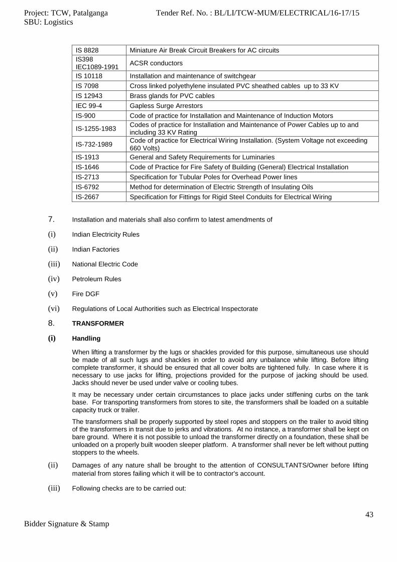
Project: TCW, Patalganga Tender Ref. No. : BL/LI/TCW-MUM/ELECTRICAL/16-17/15
SBU: Logistics
43
Bidder Signature & Stamp
IS 8828 Miniature Air Break Circuit Breakers for AC circuits
IS398 IEC1089-1991
ACSR conductors
IS 10118 Installation and maintenance of switchgear
IS 7098 Cross linked polyethylene insulated PVC sheathed cables up to 33 KV
IS 12943 Brass glands for PVC cables
IEC 99-4 Gapless Surge Arrestors
IS-900 Code of practice for Installation and Maintenance of Induction Motors
IS-1255-1983 Codes of practice for Installation and Maintenance of Power Cables up to and including 33 KV Rating
IS-732-1989 Code of practice for Electrical Wiring Installation. (System Voltage not exceeding 660 Volts)
IS-1913 General and Safety Requirements for Luminaries
IS-1646 Code of Practice for Fire Safety of Building (General) Electrical Installation
IS-2713 Specification for Tubular Poles for Overhead Power lines
IS-6792 Method for determination of Electric Strength of Insulating Oils
IS-2667 Specification for Fittings for Rigid Steel Conduits for Electrical Wiring
7. Installation and materials shall also confirm to latest amendments of
(i) Indian Electricity Rules
(ii) Indian Factories
(iii) National Electric Code
(iv) Petroleum Rules
(v) Fire DGF
(vi) Regulations of Local Authorities such as Electrical Inspectorate
8. TRANSFORMER
(i) Handling
When lifting a transformer by the lugs or shackles provided for this purpose, simultaneous use should be made of all such lugs and shackles in order to avoid any unbalance while lifting. Before lifting complete transformer, it should be ensured that all cover bolts are tightened fully. In case where it is necessary to use jacks for lifting, projections provided for the purpose of jacking should be used. Jacks should never be used under valve or cooling tubes.
It may be necessary under certain circumstances to place jacks under stiffening curbs on the tank base. For transporting transformers from stores to site, the transformers shall be loaded on a suitable capacity truck or trailer.
The transformers shall be properly supported by steel ropes and stoppers on the trailer to avoid tilting of the transformers in transit due to jerks and vibrations. At no instance, a transformer shall be kept on bare ground. Where it is not possible to unload the transformer directly on a foundation, these shall be unloaded on a properly built wooden sleeper platform. A transformer shall never be left without putting stoppers to the wheels.
(ii) Damages of any nature shall be brought to the attention of CONSULTANTS/Owner before lifting
material from stores failing which it will be to contractor's account.
(iii) Following checks are to be carried out:
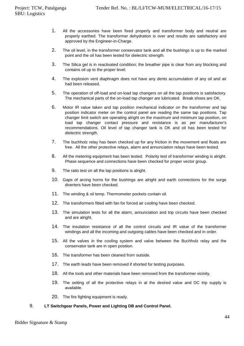
Project: TCW, Patalganga Tender Ref. No. : BL/LI/TCW-MUM/ELECTRICAL/16-17/15
SBU: Logistics
44
Bidder Signature & Stamp
1. All the accessories have been fixed properly and transformer body and neutral are
properly earthed. The transformer dehydration is over and results are satisfactory and
approved by the Engineer-in-Charge.
2. The oil level, in the transformer conservator tank and all the bushings is up to the marked
point and the oil has been tested for dielectric strength.
3. The Silica gel is in reactivated condition; the breather pipe is clear from any blocking and
contains oil up to the proper level.
4. The explosion vent diaphragm does not have any dents accumulation of any oil and air
had been released.
5. The operation of off-load and on-load tap changers on all the tap positions is satisfactory.
The mechanical parts of the on-load tap changer are lubricated. Break shoes are OK.
6. Motor IR value taken and tap position mechanical indicator on the transformer and tap
position indicator meter on the control panel are reading the same tap positions. Tap
changer limit switch are operating alright on the maximum and minimum tap position, on
load tap changer contact pressure and resistance is as per manufacturer's
recommendations. Oil level of tap changer tank is OK and oil has been tested for
dielectric strength.
7. The buchholz relay has been checked up for any friction in the movement and floats are
free. All the other protective relays, alarm and annunciation relays have been tested.
8. All the metering equipment has been tested. Polarity test of transformer winding is alright.
Phase sequence and connections have been checked for proper vector group.
9. The ratio test on all the tap positions is alright.
10. Gaps of arcing horns for the bushings are alright and earth connections for the surge
diverters have been checked.
11. The winding & oil temp. Thermometer pockets contain oil.
12. The transformers fitted with fan for forced air cooling have been checked.
13. The simulation tests for all the alarm, annunciation and trip circuits have been checked
and are alright.
14. The insulation resistance of all the control circuits and IR value of the transformer
windings and all the incoming and outgoing cables have been checked and in order.
15. All the valves in the cooling system and valve between the Buchholz relay and the
conservator tank are in open position.
16. The transformer has been cleaned from outside.
17. The earth leads have been removed if shorted for testing purposes.
18. All the tools and other materials have been removed from the transformer vicinity.
19. The setting of all the protective relays in at the desired value and DC trip supply is
available.
20. The fire fighting equipment is ready.
9. LT Switchgear Panels, Power and Lighting DB and Control Panel.
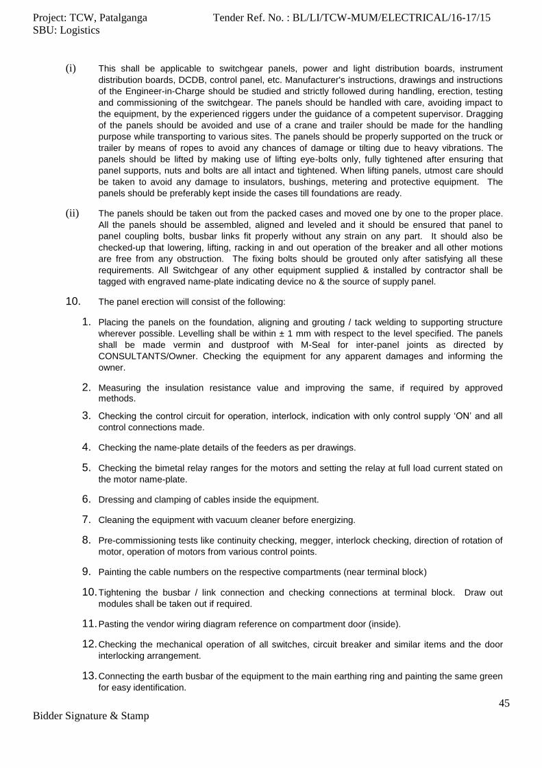
Project: TCW, Patalganga Tender Ref. No. : BL/LI/TCW-MUM/ELECTRICAL/16-17/15
SBU: Logistics
45
Bidder Signature & Stamp
(i) This shall be applicable to switchgear panels, power and light distribution boards, instrument
distribution boards, DCDB, control panel, etc. Manufacturer's instructions, drawings and instructions
of the Engineer-in-Charge should be studied and strictly followed during handling, erection, testing
and commissioning of the switchgear. The panels should be handled with care, avoiding impact to
the equipment, by the experienced riggers under the guidance of a competent supervisor. Dragging
of the panels should be avoided and use of a crane and trailer should be made for the handling
purpose while transporting to various sites. The panels should be properly supported on the truck or
trailer by means of ropes to avoid any chances of damage or tilting due to heavy vibrations. The
panels should be lifted by making use of lifting eye-bolts only, fully tightened after ensuring that
panel supports, nuts and bolts are all intact and tightened. When lifting panels, utmost care should
be taken to avoid any damage to insulators, bushings, metering and protective equipment. The
panels should be preferably kept inside the cases till foundations are ready.
(ii) The panels should be taken out from the packed cases and moved one by one to the proper place.
All the panels should be assembled, aligned and leveled and it should be ensured that panel to
panel coupling bolts, busbar links fit properly without any strain on any part. It should also be
checked-up that lowering, lifting, racking in and out operation of the breaker and all other motions
are free from any obstruction. The fixing bolts should be grouted only after satisfying all these
requirements. All Switchgear of any other equipment supplied & installed by contractor shall be
tagged with engraved name-plate indicating device no & the source of supply panel.
10. The panel erection will consist of the following:
1. Placing the panels on the foundation, aligning and grouting / tack welding to supporting structure
wherever possible. Levelling shall be within ± 1 mm with respect to the level specified. The panels
shall be made vermin and dustproof with M-Seal for inter-panel joints as directed by
CONSULTANTS/Owner. Checking the equipment for any apparent damages and informing the
owner.
2. Measuring the insulation resistance value and improving the same, if required by approved methods.
3. Checking the control circuit for operation, interlock, indication with only control supply ‘ON’ and all
control connections made.
4. Checking the name-plate details of the feeders as per drawings.
5. Checking the bimetal relay ranges for the motors and setting the relay at full load current stated on
the motor name-plate.
6. Dressing and clamping of cables inside the equipment.
7. Cleaning the equipment with vacuum cleaner before energizing.
8. Pre-commissioning tests like continuity checking, megger, interlock checking, direction of rotation of
motor, operation of motors from various control points.
9. Painting the cable numbers on the respective compartments (near terminal block)
10. Tightening the busbar / link connection and checking connections at terminal block. Draw out
modules shall be taken out if required.
11. Pasting the vendor wiring diagram reference on compartment door (inside).
12. Checking the mechanical operation of all switches, circuit breaker and similar items and the door
interlocking arrangement.
13. Connecting the earth busbar of the equipment to the main earthing ring and painting the same green
for easy identification.

Project: TCW, Patalganga Tender Ref. No. : BL/LI/TCW-MUM/ELECTRICAL/16-17/15
SBU: Logistics
46
Bidder Signature & Stamp
14. Checking the measuring and indicating instruments for operation.
15. Plugging the unused cut-outs for cable glands in the equipment after completing the cable
connections.
16. Touch-up painting of panels, wherever required.
17. Checking of all Components in Feeders with respect to vendor SLD and Bill of Material.
18. Prior to Panel hand-over, all feeder Nos. & description shall be provided on new engraved name
plates in place of old ones.
11. LT PANELS
(i) Construction
1. The switchboard shall be totally enclosed, metal clad, sheet steel fabricated,
compartmentalized, dead front type, dust and vermin-proof, freestanding, floor mounting
type. It shall be of unit construction suitable for splitting into sections for shipping to site
and to be correctly re-erected on prepared foundations without skilled supervision. The
individual shipping section length shall not preferably exceed 2 metres. Provisions shall
be made for addition of future units on either ends of a switchgear line-up after its
installation on site. End busbar fishplates shall be provided.
2. The switchgear shall be easily extensible on either side by the addition of vertical
sections. It shall be possible to extend the switchgear, irrespective of the type of end
panel and the design shall be such as to permit addition of extension panels of a type
other than the type of end panel. Any adapter panels required shall be included in the
basic price and indicated clearly in the technical particulars furnished.
3. The switchboard shall be fabricated preferably from cold rolled sheet steel of minimum
thickness 14/16 gauge.
4. The height of the switchboard shall be constant throughout its length, but not exceeding
2300 mm.
5. Adequate lifting facilities such as hooks for ease of handling on site shall be provided.
These hooks when removed shall not leave any openings in the switchgear.
6. Front access shall be available to all components in each cubicle, which require
adjustment, maintenance or replacement. Checking and removal of components shall
be possible without disturbing adjacent equipment. All auxiliary equipment shall be
easily accessible. Setting of relays shall be possible without de-energizing other
equipment.
7. Rear access shall be available to all cable glands and multicore terminal blocks by
means of sheet steel hinged doors, designed to give the maximum possible access to
the cable terminations. The cable alley door shall be provided with bolts, which can be
opened with special keys by authorised persons.
8. Each unit of switchgear shall have necessary interior barriers to form separate
compartments for buses, switching devices entering cable connection etc. All barriers
shall be manufactured from non-inflammable material, preferably of sheet steel.
9. Each compartment shall be constructed and segregated to confine any damage caused
by an internal fault to that compartment.
Project: TCW, Patalganga Tender Ref. No. : BL/LI/TCW-MUM/ELECTRICAL/16-17/15
SBU: Logistics
47
Bidder Signature & Stamp
10. Adequate barriers shall permit personnel to work safely within an empty switching
device compartment or one from which the switching device assembly has been
temporarily removed with bus energized.
11. The arrangement of feeders in the switchboard shall take into consideration the number
and size of cables required for the feeders.
12. The arrangement of the feeders shall ensure that operating handle of the switch /
breaker shall be above 300 mm but below 1800 mm from ground level.
13. Removable type undrilled gland plates shall be provided on bottom as well as top of the
panel. Gland plates shall be 3 mm thick sheet steel.
14. Suitable provision shall be made for clamping cables inside the switchboard.
15. The cable terminations inside the cable alley shall be completely shrouded so that it
shall be possible to work on any one of the terminations by switching OFF the
corresponding feeder switch only.
16. All bezels, handles, screws, bolts, washers, hinges and other embellishments shall be
of the best quality electro galvanized or passivated to withstand attack from corrosive
atmosphere.
17. The fabricated parts shall undergo a treatment of degreasing, pickling and two coats of
primer before being given the stoved enamel finish. The final finish shall be of color
shade 631 as per IS-5 or RAL-7032. Two coats of final paint shall be applied. Proper
care shall be taken to grind the welded joints to give a smooth appearance after
painting.
18. The external finish of the board shall be of the highest standard.
19. The external and internal surface of the board shall be stove enamelled finish unless
otherwise specified.
20. Adequate packaging against damage and deterioration shall be provided for
transportation to site and subsequent storage prior to re-assembly.
21. Horizontal busbar chambers shall be at the top of the board. Busbars shall be
completely shrouded to prevent metal pieces falling on the busbar during maintenance.
22. The busbars shall be of aluminium with continuous rating as given in the SLD. All
busbars and their main current carrying connections shall have preferably the same
sectional area throughout their length. The busbars shall be color coded.
23. The busbar sizes shall be determined taking into consideration the continuous rating
without exceeding the final temperature of 45o C over maximum ambient temperature
and the fault level specified. The busbars shall be supported by insulators on non-
carbonizing material resistant to acid and alkali and having non-hygroscopic
characteristics and braced to withstand the fault level specified.
24. Auxiliary busbars each of minimum size 18 sq mm copper shall be provided for
following applications. Exact number of busbars shall depend on various control,
metering and auxiliary power distribution requirements specified in specific
requirements.
1. Panel / Motor space heater supply.
2. AC / DC control supply for breaker tripping closing and indication circuits.

Project: TCW, Patalganga Tender Ref. No. : BL/LI/TCW-MUM/ELECTRICAL/16-17/15
SBU: Logistics
48
Bidder Signature & Stamp
3. AC / DC control supply for breaker spring charging motors.
4. AC control supply for motor starter control and indication circuits.
5. AC potential supply for KWH meters.
25. Earthing - Two earth terminals shall be provided on each switch cubicle, at the back,
near the floor. An earth bar of at least 50 x 6 mm copper shall be fixed to these
terminals. The earth bar shall be electrically continuous and shall run the full extent of
each board. Each unit shall be constructed to ensure satisfactory electrical continuity
between all metal parts not intended to be alive and earth terminals of the unit. Suitable
holes with bolts and lugs shall be provided at each end of earth bar of switchgear for
connection to a main earthing grid of 50 x 6 mm GI bus. The earth bar shall be
accessible in each cable entering compartment either directly or through a branch
extension to ground the cable armour and shields.
26. Busbars and connections shall be secured in such a manner that the insulators are not
subjected to bending forces under short circuit conditions. The vertical dropper shall be
sized to carry continuously at least the rated current of the connected switching devices.
When multiple switching devices are combined in tiers for a vertical unit, the droppers
shall be able to carry the total current resulting from the combination of all switching
devices. The vertical busbars shall be completely shrouded with the cut-out for
connection tappings.
27. In case of copper to aluminium connections, proper treatment shall be given to minimize
the bimetallic effect. That is, all joint surfaces at aluminium to copper joints shall be
silver / tin plated, alternatively Cu-Al. washers (bimetallic washers) may be used.
28. Any unused circuit breaker compartment shall be fully equipped and provided with
compartment door, vertical bus bars and control terminals / wiring, etc., such that the
same could be used for housing outgoing breakers in future without any modifications to
the panel. All quotations must indicate the number of circuit breakers, which could be
provided in unused space for each switchboard line up. Unit price for providing such
outgoing circuit breakers shall be quoted which could be considered during placement
of order.
29. The arrangement of feeders in the switchboard shall take into consideration the number
and size of cables required for the feeders.
30. Incomer and Bus Coupler ACB shall be limited to one per panel. (SLD supersedes this
requirement)
31. Nameplate or polyester adhesive stickers shall be provided for each equipment (lamps,
push buttons, switches, relays, auxiliary contactors, etc.) mounted on the switchboard.
Special warning plates one each on each front of a shipping section shall be provided
on removable covers of doors giving access to cable terminals and busbars. Special
warning labels shall be provided inside the switchboard also, wherever considered
necessary. Identification tags shall be provided inside the panels matching with those
shown on the circuit diagram.
32. Engraved nameplates shall preferably be of 3 ply (Black-White Black) lamicoid sheets
or anodized aluminium. Nameplates shall be fastened by screws and not by adhesives.
33. ACB feeders for outgoing shall be limited three per panel subject to owner’s approval on
GA diagram.
34. SFU feeders for outgoing shall be limited to three per panel.

Project: TCW, Patalganga Tender Ref. No. : BL/LI/TCW-MUM/ELECTRICAL/16-17/15
SBU: Logistics
49
Bidder Signature & Stamp
35. The feeders shall be arranged in the ascending order of alphabets followed by
ascending order of equipment, e.g. A33801, M3402, and P211.
36. Manufacturer shall furnish the general arrangement drawing of switchboard along with
the quotation. The General Arrangement drawing of switchboard shall be subject to
Owner's approval.
(ii) CIRCUIT BREAKERS
The circuit breaker shall be triple pole, air break, and draw out type with solid manually detachable type neutral. Unless otherwise stated elsewhere, the circuit breakers shall be draw out type.
1. The charging mechanism of the circuit breaker shall be manual / motor operated spring
charged independent type. The close / trip control switch to be interlocked to trip before
close. The closing and tripping circuits shall be self-opening on completion of their
respective functions irrespective of the position of the control switch. Manual closing
devices shall also be provided.
2. The circuit breaker shall be electrically and mechanically trip free. For all electrical circuit
breakers anti-pumping device shall be incorporated.
3. The breaker shall be provided with minimum 6NO + 6NC auxiliary contacts. 20% auxiliary
contacts (Min. 3 NO + 3 NC) shall be provided for Owner's exclusive use. All spare
contacts shall be wired up to terminal blocks. Auxiliary contactor or relay shall be used
to multiply contacts.
4. The auxiliary contact for the shunt trip shall be of advanced nature such that the auxiliary
contact close before main contacts.
5. The main and secondary isolating contacts of the circuit breaker shall be of self-aligning
type.
6. The main isolating contact shall have continuous rating equal to the rating of the breaker.
7. The secondary isolating contact shall be of wiping contact type.
8. The fixed portion of the circuit breaker shall have rail arrangement over which the chassis
can move smoothly.
9. It shall be possible to bring the circuit breaker to isolated position with the help of external
lever without opening the compartment door.
10. The breaker shall have 3 distinct positions, such as "SERVICE", "TEST" and
"ISOLATED".
11. Proper mechanical indication shall be provided to locate these three positions without
opening the compartment door.
12. It shall be possible to further withdraw the breaker from isolated position for inspection of
the circuit breaker "withdrawn" position.
13. A stop block shall be provided on the slide rails to prevent the forward movement of the
circuit breaker when it reaches the isolated position so that any accidental fall can be
avoided. Provision shall be provided to padlock the breaker in all the three positions.
14. A stop block shall be provided on the slide rails to prevent the forward movement of the
circuit breaker when it reaches the isolated position so that any accidental fall can be
avoided. Provision shall be provided to padlock the breaker in all the three positions.
15. The following interlocks shall be provided on the circuit breaker:

Project: TCW, Patalganga Tender Ref. No. : BL/LI/TCW-MUM/ELECTRICAL/16-17/15
SBU: Logistics
50
Bidder Signature & Stamp
It shall not be possible to withdraw the circuit breaker from the service position with
the contacts of the breaker closed.
It shall not be possible to close the circuit breaker unless any one of the three
positions is located, the service position, a definitely located test position, or isolated
position.
It shall not be possible to open the compartment door when the circuit breaker is
ON.
It shall not be possible to push breaker in if either set of safety shutter is not free
and not in its normal closed position.
The circuit breaker can be padlocked in OFF position.
The castle interlocking shall be provided as per the SLD.
16. The circuit breaker shall be provided with mechanical ON/OFF, TRIP and SPRING
CHARGED indication, mechanical trip push button, operating handle or `close' push
button, in case of electrically operated circuit breaker and padlocking facility wherever
specified.
17. In case of electrically operated breaker, emergency operating handle shall be provided.
18. It shall be possible to close the circuit breaker with the emergency operating handle
without opening the compartment door.
19. Wherever cutouts are provided for the control box, proper gaskets shall be provided.
Provision shall be made for closing the cutout provided for the control boxes when the
C.B. is taken out of the compartment.
20. The circuit breaker shall be provided with automatic safety shutters, so that before the
breaker reaches `isolated' position the main isolating contacts are completely shrouded.
21. The circuit breaker compartment shall be so designed that hot gases produced shall be
lead away from the operator.
22. The protective relays and instruments shall be mounted as near to the circuit breaker as
possible. Separate compartment for the instruments and relays shall be provided.
23. When the circuit breaker compartment door is open, it must not be possible to touch the
live parts.
24. All removable covers protecting live parts shall be clearly labelled with warning notices
reading "LIVE PARTS. ISOLATE ELSEWHERE BEFORE REMOVING COVER'.
25. It shall be possible to readily remove the arc chutes for routine inspection of the contacts
with the circuit breaker in the "withdrawn" position.
26. All circuit breakers of same rating shall be identical in all respects and shall be
interchangeable.
27. All the non-conducting metal parts of the circuit breaker trolley shall be bonded together
and shall make perfect electrical connection to earth through substantial sliding contacts,
at service and test positions. Such sliding contacts shall be arranged to make before
power plug in and interrupt after power draw out.
(iii) Switches
1. The switches shall be quick-make, quick-break heavy-duty type.
2. The switches shall be able to make and break 300% of the rated current at 0.3 P.F. as
required by IS-4047.
Project: TCW, Patalganga Tender Ref. No. : BL/LI/TCW-MUM/ELECTRICAL/16-17/15
SBU: Logistics
51
Bidder Signature & Stamp
3. The operating handle shall be mounted on the door of the compartment housing the
switches. The switches shall be provided with an interlocking arrangement such that when
the switch is ON it shall not be possible to open the compartment door.
4. It shall also be ensured that closing of the switch when the compartment door is open
shall not be possible.
5. To facilitate closing of switch with door open during maintenance / testing, interlock defeat
mechanism shall be provided.
6. The castle interlock shall be provided, wherever specified in the SLD.
7. In case of switch fuse feeders, the switch rating shall be equal or greater than the fuse
rating.
8. The switch shall be provided with padlocking facility in OFF position.
9. All removable covers protecting live parts shall be clearly labeled with warning notices
reading "LIVE PARTS. ISOLATE ELSEWHERE BEFORE REMOVING COVER".
10. Rating of the switches shall be as given in the SLD.
(iv) HRC Fuses
1. Fuses provided shall have rupturing capacity greater than the fault level specified.
2. Fuses shall be of link type and shall conform to the relevant Indian Standards. They shall
be of class 3 AC duty.
3. Fuses for motor feeders shall be decided taking into consideration bimetal relay
characteristics provided.
4. Rating of the fuses shall be as given in the SLD.
5. Delayed action fuses shall be preferred for motor feeders.
6. Indication shall be provided in the fuses to indicate the fuse has operated. Operating
indicator shall be visible without removal of fuses from service. Removal of fuses,
however, must be possible, although full voltage may exist at the terminals. Fuses shall
be pressure fitted type.
7. Fuse handle shall be supplied along with switchboard.
(v) Contactors
The air break contactors shall be of triple pole type. Contactor shall have at least 2NO + 2NC contacts for owner's use. The auxiliary contacts shall be wired to the terminals. The contactor coil shall be suitable for control voltage of 230V AC. The coils shall have grade ‘E’ insulation and shall be suitable for use in the ambient temperature. The design of the contactor shall ensure easy access to auxiliary contacts and coil. Mechanical ON-OFF indication shall be provided for the contactors. Wherever mechanical indications are not provided, indicating lamps shall be provided for ON indication of the contactor. The contactor shall pick up at 85% of the control voltage and shall not drop out for voltage up to 45%. The control voltage for motor starter circuit shall be 240V, single phase, 50 Hz, unless otherwise specified.
(vi) Relays
1. The relays shall conform to the requirements of IS-3231 and IS-4483.
2. All relays specified shall be flush mounted in dust proof cases and shall match the
appearance of the instruments mounted on the same panel.

Project: TCW, Patalganga Tender Ref. No. : BL/LI/TCW-MUM/ELECTRICAL/16-17/15
SBU: Logistics
52
Bidder Signature & Stamp
3. Protective relays shall be of the easy withdraw-able type. Trip circuits shall be
automatically broken and current transformer secondary circuits shorted, when a relay is
withdrawn from its case. A marking strip shall be provided in front of each terminal block
and a diagram plate at the back of each case to identify connections.
4. Relays contacts shall withstand repeated operation and shall make or break the maximum
currents in their circuits without deterioration. All spare contacts shall also be wired up to
the external terminals.
5. Relay coils shall carry their normal currents indefinitely and such currents as can occur
under fault conditions. Relay mechanisms shall not be affected by vibration or magnetic
fields, which may occur in normal operation.
6. All relays in tripping circuits shall have mechanically operated flag indications. Indicators
shall be capable of being reset without opening the relay case. It shall not be possible to
operate any relay by hand or to alter its setting without opening the case. For relays with
combined functions such as inverse time and instantaneous trip, separate indications of
each function as specified shall be provided.
7. Master tripping relay (Lock-out Relay) shall be of the hand reset type and shall have a
reasonable number of spare contacts, both normally open and normally closed, in addition
to those required by the protection and tripping scheme.
8. Provision shall be made for insertion of test plug at the front for testing and calibration
using external source of power without disconnecting permanent wiring. Test plugs shall
permit the shorting of any current transformer circuit.
9. Relay covers shall be of non-ignitable materials. Relays on which the function of a
contact may be changed from NC to NO and vice-versa by simply changing the contact
arrangement are preferred.
10. All relays pertaining to a feeder shall be accommodated in the same vertical section.
(vii) Bimetal Relay
Bimetal relays shall be heavy duty, (wherever mentioned) ambient temperature compensated type. The selection of bimetal relays shall be based on the absorbed horsepower of motor given in the data sheet. Proper co-ordination shall be ensured between bimetal relay and the back-up HRC fuse provided. The bimetal relay shall be of hand reset type preferably with facility to change to self-reset at site, if necessary. The bimetal relay shall be provided with changeover contact for alarm indication. It shall be possible to reset the relay only after opening the compartment door, if so specified. BMRs shall be with built in single phasing protection. Equipment like fans, blowers, etc., shall be provided with suitable saturable CT operated BMR. For saturable CT operated BMR, Single Phasing Protection Relay shall be separate, if specified.
(viii) SINGLE PHASING PREVENTER RELAY (SPPR)
1. If specified Single Phasing Protections shall be provided in all motor starter modules with
contactor rating of 200 Amps and above. The Single Phasing Protection shall be of the
current operated type and shall operate on the principle of sensing negative sequence of
current.
2. In case of single phasing, the Single Phasing Protection shall operate after a time delay of
2 to 3 sec. The relay shall be of the hand reset type and visual indication of the relay
operation shall be available.
3. The Single Phasing Protection shall be suitable for protection of the non-reversible and
reversible motors.
4. Current transformer operated Single Phasing Protection Relay shall be provided for
feeders, if specified.

Project: TCW, Patalganga Tender Ref. No. : BL/LI/TCW-MUM/ELECTRICAL/16-17/15
SBU: Logistics
53
Bidder Signature & Stamp
5. Thermal overload relays shall be provided with minimum 1NO + 1NC contacts with a
rating of 5 Amps at 240V, 1 phase, 50 Hz AC and 1.3 Amps at 110 V DC (inductive load).
(ix) Indicating Instruments & Meters
1. All indicating instruments and meters shall be capable of carrying continuously their full
load currents and full voltage across their pressure coils. They shall not be damaged by
the passage of fault currents or the existence of over pressure on the primary side of their
instrument transformers for the maximum permitted duration of fault conditions, which
may occur during normal operation. All instruments and meters shall be back connected.
2. For incoming feeders, measuring instruments shall be of 96 x 96 mm square pattern, flush
mounting type, 72 x 72 mm instruments shall be used for outgoing feeders. Instruments
shall be provided wherever indicated in specific requirements. All auxiliary equipment such
as shunts, transducers, CTs, VTs that are required shall be included in the supply of the
switchboard.
3. All AC ammeters, voltmeters, KW meters shall be of moving iron type for AC and permanent
magnet type for DC. Accuracy class shall be 1.0 for KW / KWH meters and 1.5 for
ammeters and voltmeters as per IS: 1248. The range shall be as indicated in the SLD.
Ammeters for motor feeders shall have non-linear compressed scale at the end to indicate
motor starting current. Voltmeter shall be suitable for direct line connection.
4. KWH meters and KVARH meters shall be of registering type and shall be installed inside unit but
readable without opening doors. KWH meters shall be with maximum demand indicator in
KVA.
5. KW, KWH and power factor meters shall be suitable for 3 phases, 4 wire unbalanced system with
voltage coil suitable for 230V AC. The current coils shall also be suitable as given in SLD.
6. Instruments shall be mounted above 900 mm but below 2000 mm from the base channel of the
switchboard.
7. They shall be provided with zero adjusting devices for external operation.
8. Indicating instruments and protective relay for respective feeder shall be located either in the
same panel or in adjoining panel and shall be grouped together.
(x) Multifunction Meters
1. General Requirements
The meter shall be suitable for operation in single - or multi-phase networks, balanced
as well as unbalanced load.
It shall be possible to use the multifunction meter directly in 690V networks.
The current inputs shall be configurable at site for measuring on x/1 A or x/5 A current
transformers.
The multifunction meters shall be suitable for operation up to 55 Deg C.
The meters shall be suitable for operation with AC auxiliary power and shall have
wide tolerance band of 95V to 240 V (±10%).
The multifunction meters shall have high degree of protection (IP65 from the front)
against ingress of dust & water.
The multifunction meters shall have backlit LCD display with adjustable contrast.
Project: TCW, Patalganga Tender Ref. No. : BL/LI/TCW-MUM/ELECTRICAL/16-17/15
SBU: Logistics
54
Bidder Signature & Stamp
The meter shall be tamper-proof (password protected) to avoid mishandling by
unauthorized person.
All Main & DG incomers and important feeders shall be provided with Digital LOAD
MANAGERS unless otherwise specified instead of regular meters. LOAD
MANAGERS shall provide minimum voltages, currents, KW, KVA, KWH, KVA, Rh,
frequency, cos Ø, % harmonics, Maximum demand KVA reading with scrolling. These
will be with RS 485 port for down loading data. LOAD MANAGER should be able to
store last 8 days data, which can be downloaded. Necessary software for Load
Manager shall be provided.
2. Measured Values requirement
All metered values will be in "true RMS" values. The monitor shall include a keypad allowing for the viewing of different selected values. The monitor shall display the following values.
Voltages Phase-phase / phase-neutral
Currents Per phase
Apparent, active and reactive power
Per phase and total
Power factor Per phase and total
Frequency 45...64 Hz
THD for voltage and current Per phase
Min. / max. values Voltage - phase-phase, phase-neutral, Current / Power / Power factor / THD per phase, Frequency, Three phase average voltage and current
Average values Voltage - phase-phase, phase-neutral Voltage min. / max. for phase-phase, phase-neutral. Current min. / max.
Active energy Import / export; high / low tariff
Reactive energy Positive / negative; high / low tariff
Apparent energy High / low tariff
Energy demand per measuring period
Three phase average rating for active and reactive power: 1 to 60 min
Min. / max. rating values within the measuring period
Should be possible to be measured
3. The meter shall have at least 1 Digital Input and 1 Digital Output as standard. It shall be possible
to switch between High-tariff and Low-tariff via the digital input or the communication
interfaces.
4. The device shall allow for monitoring of upper or lower limit values for parameters like V, I, p.f
etc. It should be also possible to build in logics so that multiple limit criteria are addressed.
In case of limit violation, it shall be possible for triggering specified actions through the
digital output of the meter.
5. Communication
The meters shall be capable of communicating the measured parameters via high speed (preferably 1.5mbps) open protocol bus system like profibus or others. It shall be possible to parameterize the device either by the keys on the device or through parameterization software.
Project: TCW, Patalganga Tender Ref. No. : BL/LI/TCW-MUM/ELECTRICAL/16-17/15
SBU: Logistics
55
Bidder Signature & Stamp
(xi) Current Transformer
1. The Current Transformers shall be Resin cast bar primary / wound primary type. The burden
ratio shall be minimum as indicated in Specific Requirements. However, current
transformers shall have sufficient capacity to operate with the burden imposed by the
devices shown on drawings with their accuracy classification. Separate cores shall be
used for metering and protection.
2. Current transformers for instruments shall have an accuracy class 1.0 and accuracy limit factor
less than 5.0. However, accuracy class 3.0 is acceptable for ammeters only. If a
metering load is fed from a protection CT, suitable 1/1 or 5/5 ratio saturable interposing
CTs shall be used.
3. The current transformers shall be capable to withstand dynamic and thermal stresses originated
by the fault current.
4. The CTs shall be suitably insulated and the mounting of the CTs shall facilitate easy
maintenance.
5. The CTs shall be mounted in stationary part of switchgear.
6. The secondary of the CTs for metering when wired to terminals, shorting links shall be provided.
Shorting links shall be of removable type of Wago make.
7. For proper relaying, one side of current transformer secondary shall be grounded in the
compartment with the meters or relays, which they serve, and each CT group shall be
grounded with a separate identified lead, which may be disconnected for testing.
(xii) Potential Transformer
1. The potential transformers wherever provided shall be epoxy cast resin type and shall have class
of burden minimum as given in the SLD. However, potential transformers shall have
sufficient capacity to operate with the burden imposed by the devices shown on the
drawing with their accuracy classification.
2. The voltage transformers shall have an accuracy class 3.0 from 50% to 110% of normal voltage
and class 1.0 from 80% to 120% of normal voltage with burdens varying between 25% to
100% of the rated value at 0.8 PF lagging.
3. The primary of the voltage transformers shall be rated for 415 volts and the secondary for 110
volts.
4. The PT shall be provided with HRC fuse on the primary side and secondary side.
5. The PT shall be mounted in a separate compartment complete with its accessories.
6. For proper relaying, one side of PT secondary shall be grounded at the transformer and the
ground connection shall be identified and removable for testing.
7. Test terminals shall be provided for PT circuits.
(xiii) Timer
For reacceleration duty, timers unless otherwise stated, shall be pneumatic type and shall have adjustable time setting of 0 - 60 secs. The time settings, where specified shall be accurately set before dispatch of the switchboard.
Timers for auto-transfer schemes shall be of static type with timing ranges suitable for the scheme employed.
(xiv) Indicating Lamps
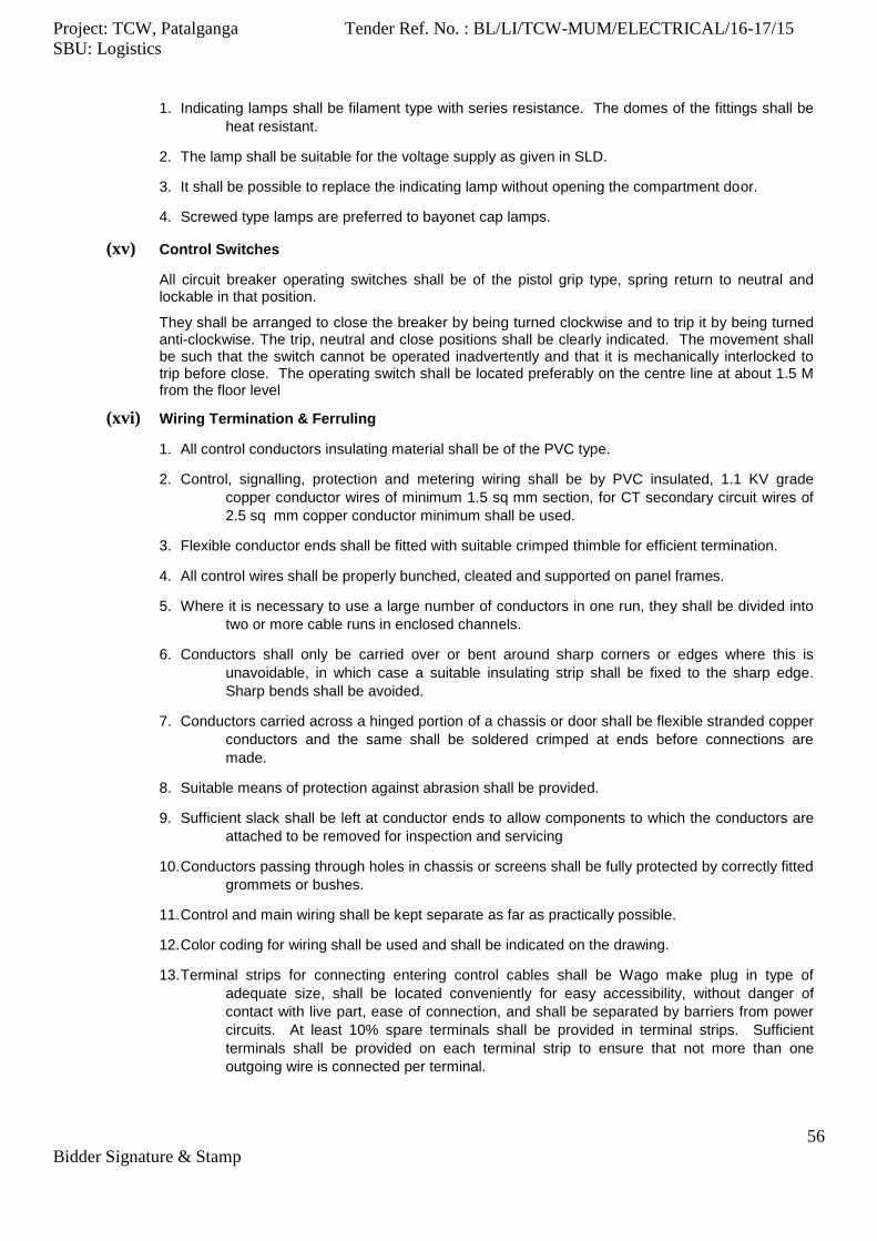
Project: TCW, Patalganga Tender Ref. No. : BL/LI/TCW-MUM/ELECTRICAL/16-17/15
SBU: Logistics
56
Bidder Signature & Stamp
1. Indicating lamps shall be filament type with series resistance. The domes of the fittings shall be
heat resistant.
2. The lamp shall be suitable for the voltage supply as given in SLD.
3. It shall be possible to replace the indicating lamp without opening the compartment door.
4. Screwed type lamps are preferred to bayonet cap lamps.
(xv) Control Switches
All circuit breaker operating switches shall be of the pistol grip type, spring return to neutral and lockable in that position.
They shall be arranged to close the breaker by being turned clockwise and to trip it by being turned anti-clockwise. The trip, neutral and close positions shall be clearly indicated. The movement shall be such that the switch cannot be operated inadvertently and that it is mechanically interlocked to trip before close. The operating switch shall be located preferably on the centre line at about 1.5 M from the floor level
(xvi) Wiring Termination & Ferruling
1. All control conductors insulating material shall be of the PVC type.
2. Control, signalling, protection and metering wiring shall be by PVC insulated, 1.1 KV grade
copper conductor wires of minimum 1.5 sq mm section, for CT secondary circuit wires of
2.5 sq mm copper conductor minimum shall be used.
3. Flexible conductor ends shall be fitted with suitable crimped thimble for efficient termination.
4. All control wires shall be properly bunched, cleated and supported on panel frames.
5. Where it is necessary to use a large number of conductors in one run, they shall be divided into
two or more cable runs in enclosed channels.
6. Conductors shall only be carried over or bent around sharp corners or edges where this is
unavoidable, in which case a suitable insulating strip shall be fixed to the sharp edge.
Sharp bends shall be avoided.
7. Conductors carried across a hinged portion of a chassis or door shall be flexible stranded copper
conductors and the same shall be soldered crimped at ends before connections are
made.
8. Suitable means of protection against abrasion shall be provided.
9. Sufficient slack shall be left at conductor ends to allow components to which the conductors are
attached to be removed for inspection and servicing
10. Conductors passing through holes in chassis or screens shall be fully protected by correctly fitted
grommets or bushes.
11. Control and main wiring shall be kept separate as far as practically possible.
12. Color coding for wiring shall be used and shall be indicated on the drawing.
13. Terminal strips for connecting entering control cables shall be Wago make plug in type of
adequate size, shall be located conveniently for easy accessibility, without danger of
contact with live part, ease of connection, and shall be separated by barriers from power
circuits. At least 10% spare terminals shall be provided in terminal strips. Sufficient
terminals shall be provided on each terminal strip to ensure that not more than one
outgoing wire is connected per terminal.
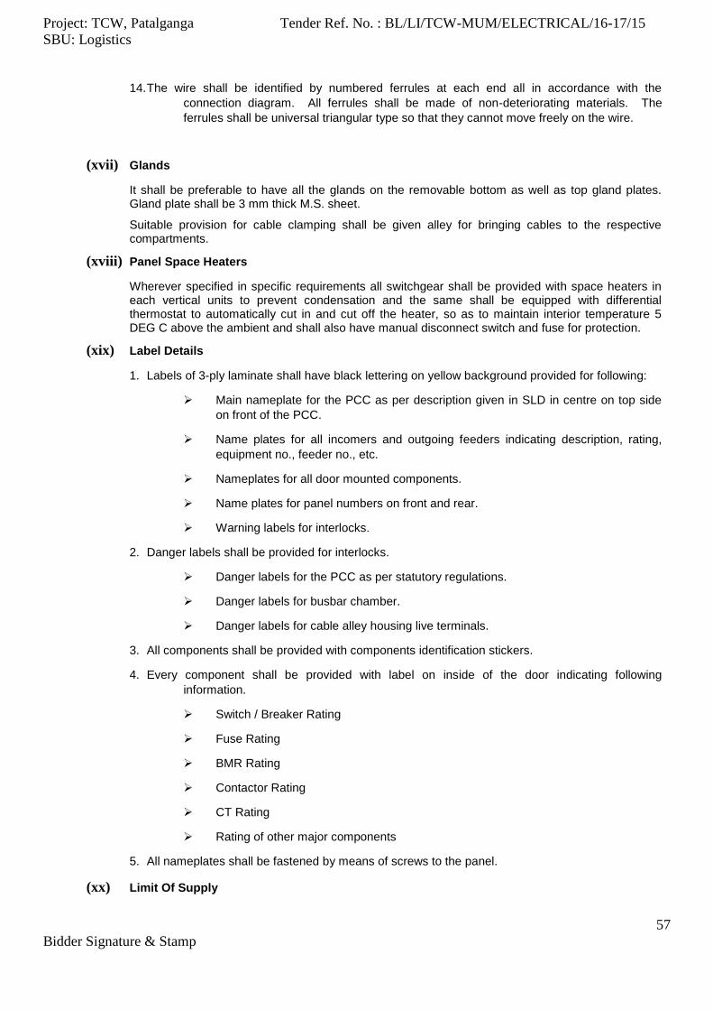
Project: TCW, Patalganga Tender Ref. No. : BL/LI/TCW-MUM/ELECTRICAL/16-17/15
SBU: Logistics
57
Bidder Signature & Stamp
14. The wire shall be identified by numbered ferrules at each end all in accordance with the
connection diagram. All ferrules shall be made of non-deteriorating materials. The
ferrules shall be universal triangular type so that they cannot move freely on the wire.
(xvii) Glands
It shall be preferable to have all the glands on the removable bottom as well as top gland plates. Gland plate shall be 3 mm thick M.S. sheet.
Suitable provision for cable clamping shall be given alley for bringing cables to the respective compartments.
(xviii) Panel Space Heaters
Wherever specified in specific requirements all switchgear shall be provided with space heaters in each vertical units to prevent condensation and the same shall be equipped with differential thermostat to automatically cut in and cut off the heater, so as to maintain interior temperature 5 DEG C above the ambient and shall also have manual disconnect switch and fuse for protection.
(xix) Label Details
1. Labels of 3-ply laminate shall have black lettering on yellow background provided for following:
Main nameplate for the PCC as per description given in SLD in centre on top side
on front of the PCC.
Name plates for all incomers and outgoing feeders indicating description, rating,
equipment no., feeder no., etc.
Nameplates for all door mounted components.
Name plates for panel numbers on front and rear.
Warning labels for interlocks.
2. Danger labels shall be provided for interlocks.
Danger labels for the PCC as per statutory regulations.
Danger labels for busbar chamber.
Danger labels for cable alley housing live terminals.
3. All components shall be provided with components identification stickers.
4. Every component shall be provided with label on inside of the door indicating following
information.
Switch / Breaker Rating
Fuse Rating
BMR Rating
Contactor Rating
CT Rating
Rating of other major components
5. All nameplates shall be fastened by means of screws to the panel.
(xx) Limit Of Supply

Project: TCW, Patalganga Tender Ref. No. : BL/LI/TCW-MUM/ELECTRICAL/16-17/15
SBU: Logistics
58
Bidder Signature & Stamp
The supply of switchgear shall include the switchgear itself complete with all normal components and devices required for full and proper operation of the equipment even though such components or devices may not be shown in detail on drawings.
Switchgear shall be in working order provided with the following auxiliary components necessary for normal and safe maintenance and operation.
1. Special tools - Complete set of special tools shall include all necessary devices for lifting,
installing, withdrawing, testing and maintaining the circuit breakers, contactors, fuses,
relays and other components of the switchgear.
2. 2 Nos. handles for removing fuses shall be delivered with each switchgear.
3. 6 Nos. lamp grips for removing and replacing of indicating lamps.
4. 1 No. test plug for Relays.
(xxi) Commissioning and Start Up Supervision
Commissioning and start-up supervision shall be provided by the manufacturer at site, and charges for the same shall be quoted separately
(xxii) Switchgear and Equipment Certification
Manufacturer shall state in its bid whether proposed circuit breakers and switchgears have been tested by an independent recognized testing organization. Copy of such test certificates shall be attached to the bid.
(xxiii) Packing
1. The switchboard shall be shipped to site packed in wooden crates. They shall be wrapped in
polyethylene sheets before being placed in crates to prevent damage to the finish. Crates
shall have skid bottoms for handling.
2. The packing cases shall be marked as per the details given in the purchase order.
3. Each case shall have the reference to the vendor general arrangement drawing and shall
normally indicate the sections of the switchgear.
4. The packing cases shall contain one set of all the drawings for easy inspection at site.
(xxiv) Statuary Regulation
The switchgear shall be manufactured as per the requirements of Indian Electricity Rules. The switchgear shall be acceptable to the local statutory authorities such as Electrical Inspectorate and Fire Insurance Council. The switchgear shall have approval of Tariff Advisory Committee and relevant certificates shall be furnished in six sets for records.
(xxv) Spares
Manufacturer shall quote for recommended spares for 2 years and for spare fuses.
(xxvi) Testing
1. 415V switchgear shall be tested as per relevant Indian Standards and will include the following:
Visual and dimensional inspection as per general arrangement drawing.
Checking for provision of feeders as per general arrangement drawing.
Checking for provision of components as per bill of material.
Operation test.
IR measurement before and after HV test.
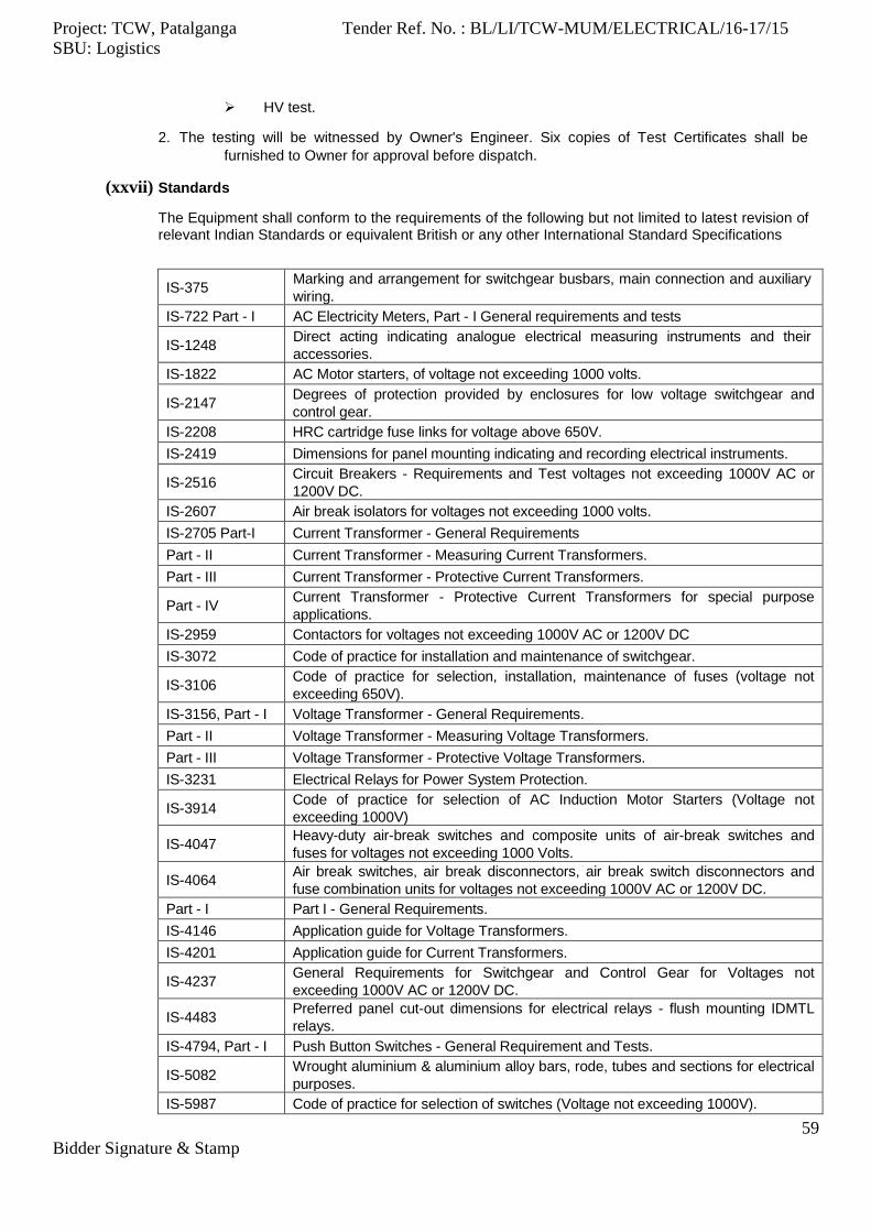
Project: TCW, Patalganga Tender Ref. No. : BL/LI/TCW-MUM/ELECTRICAL/16-17/15
SBU: Logistics
59
Bidder Signature & Stamp
HV test.
2. The testing will be witnessed by Owner's Engineer. Six copies of Test Certificates shall be
furnished to Owner for approval before dispatch.
(xxvii) Standards
The Equipment shall conform to the requirements of the following but not limited to latest revision of relevant Indian Standards or equivalent British or any other International Standard Specifications
IS-375 Marking and arrangement for switchgear busbars, main connection and auxiliary
wiring.
IS-722 Part - I AC Electricity Meters, Part - I General requirements and tests
IS-1248 Direct acting indicating analogue electrical measuring instruments and their
accessories.
IS-1822 AC Motor starters, of voltage not exceeding 1000 volts.
IS-2147 Degrees of protection provided by enclosures for low voltage switchgear and
control gear.
IS-2208 HRC cartridge fuse links for voltage above 650V.
IS-2419 Dimensions for panel mounting indicating and recording electrical instruments.
IS-2516 Circuit Breakers - Requirements and Test voltages not exceeding 1000V AC or
1200V DC.
IS-2607 Air break isolators for voltages not exceeding 1000 volts.
IS-2705 Part-I Current Transformer - General Requirements
Part - II Current Transformer - Measuring Current Transformers.
Part - III Current Transformer - Protective Current Transformers.
Part - IV Current Transformer - Protective Current Transformers for special purpose
applications.
IS-2959 Contactors for voltages not exceeding 1000V AC or 1200V DC
IS-3072 Code of practice for installation and maintenance of switchgear.
IS-3106 Code of practice for selection, installation, maintenance of fuses (voltage not
exceeding 650V).
IS-3156, Part - I Voltage Transformer - General Requirements.
Part - II Voltage Transformer - Measuring Voltage Transformers.
Part - III Voltage Transformer - Protective Voltage Transformers.
IS-3231 Electrical Relays for Power System Protection.
IS-3914 Code of practice for selection of AC Induction Motor Starters (Voltage not
exceeding 1000V)
IS-4047 Heavy-duty air-break switches and composite units of air-break switches and
fuses for voltages not exceeding 1000 Volts.
IS-4064 Air break switches, air break disconnectors, air break switch disconnectors and
fuse combination units for voltages not exceeding 1000V AC or 1200V DC.
Part - I Part I - General Requirements.
IS-4146 Application guide for Voltage Transformers.
IS-4201 Application guide for Current Transformers.
IS-4237 General Requirements for Switchgear and Control Gear for Voltages not
exceeding 1000V AC or 1200V DC.
IS-4483 Preferred panel cut-out dimensions for electrical relays - flush mounting IDMTL
relays.
IS-4794, Part - I Push Button Switches - General Requirement and Tests.
IS-5082 Wrought aluminium & aluminium alloy bars, rode, tubes and sections for electrical
purposes.
IS-5987 Code of practice for selection of switches (Voltage not exceeding 1000V).
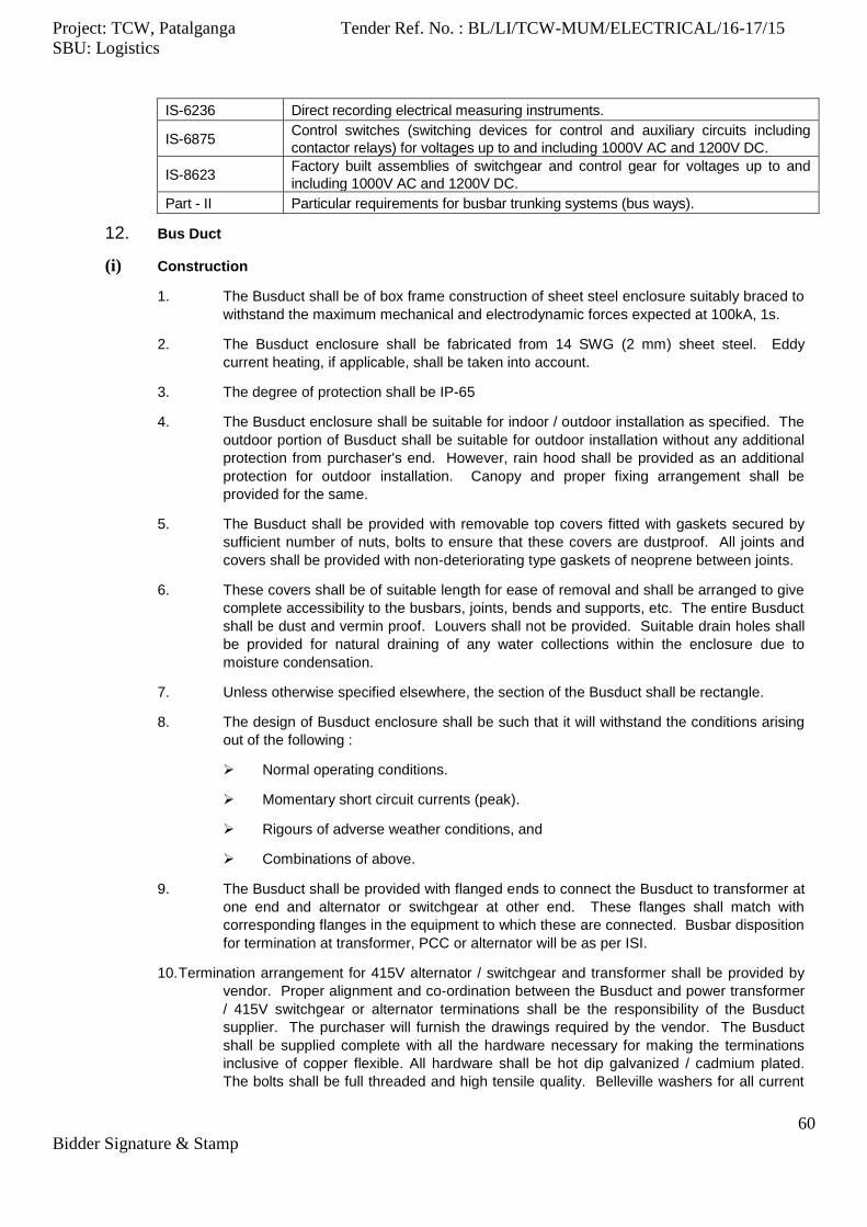
Project: TCW, Patalganga Tender Ref. No. : BL/LI/TCW-MUM/ELECTRICAL/16-17/15
SBU: Logistics
60
Bidder Signature & Stamp
IS-6236 Direct recording electrical measuring instruments.
IS-6875 Control switches (switching devices for control and auxiliary circuits including
contactor relays) for voltages up to and including 1000V AC and 1200V DC.
IS-8623 Factory built assemblies of switchgear and control gear for voltages up to and
including 1000V AC and 1200V DC.
Part - II Particular requirements for busbar trunking systems (bus ways).
12. Bus Duct
(i) Construction
1. The Busduct shall be of box frame construction of sheet steel enclosure suitably braced to
withstand the maximum mechanical and electrodynamic forces expected at 100kA, 1s.
2. The Busduct enclosure shall be fabricated from 14 SWG (2 mm) sheet steel. Eddy
current heating, if applicable, shall be taken into account.
3. The degree of protection shall be IP-65
4. The Busduct enclosure shall be suitable for indoor / outdoor installation as specified. The
outdoor portion of Busduct shall be suitable for outdoor installation without any additional
protection from purchaser's end. However, rain hood shall be provided as an additional
protection for outdoor installation. Canopy and proper fixing arrangement shall be
provided for the same.
5. The Busduct shall be provided with removable top covers fitted with gaskets secured by
sufficient number of nuts, bolts to ensure that these covers are dustproof. All joints and
covers shall be provided with non-deteriorating type gaskets of neoprene between joints.
6. These covers shall be of suitable length for ease of removal and shall be arranged to give
complete accessibility to the busbars, joints, bends and supports, etc. The entire Busduct
shall be dust and vermin proof. Louvers shall not be provided. Suitable drain holes shall
be provided for natural draining of any water collections within the enclosure due to
moisture condensation.
7. Unless otherwise specified elsewhere, the section of the Busduct shall be rectangle.
8. The design of Busduct enclosure shall be such that it will withstand the conditions arising
out of the following :
Normal operating conditions.
Momentary short circuit currents (peak).
Rigours of adverse weather conditions, and
Combinations of above.
9. The Busduct shall be provided with flanged ends to connect the Busduct to transformer at
one end and alternator or switchgear at other end. These flanges shall match with
corresponding flanges in the equipment to which these are connected. Busbar disposition
for termination at transformer, PCC or alternator will be as per ISI.
10. Termination arrangement for 415V alternator / switchgear and transformer shall be provided by
vendor. Proper alignment and co-ordination between the Busduct and power transformer
/ 415V switchgear or alternator terminations shall be the responsibility of the Busduct
supplier. The purchaser will furnish the drawings required by the vendor. The Busduct
shall be supplied complete with all the hardware necessary for making the terminations
inclusive of copper flexible. All hardware shall be hot dip galvanized / cadmium plated.
The bolts shall be full threaded and high tensile quality. Belleville washers for all current

Project: TCW, Patalganga Tender Ref. No. : BL/LI/TCW-MUM/ELECTRICAL/16-17/15
SBU: Logistics
61
Bidder Signature & Stamp
carrying conducting parts of the busbars and plain washers shall be provided for every
bolt.
11. Filter type drain holes shall be provided for draining out condensed moisture. The filter element
shall be such that it will allow escape of moisture but prevent ingress of dust. This shall
be removable type for cleaning purposes.
12. The transformer and the alternator / switchgear flanges are generally top-top connection.
13. Bolted inspection cover shall be provided wherever necessary. However, at the wall crossing of
the Busduct, there should not be any removable type inspection cover.
14. Proper wall sealing arrangements shall be provided at the wall where bus duct enters the
substation building. Busduct with wall mounting flange will be acceptable for the sealing
arrangement.
15. Top covers of the Busduct shall be so located that they will not fall within the wall crossing
section. Busduct shall be supported from overhead hangers inside the substation.
16. The enclosure shall be provided with suitable mounting lugs at suitable interval. The mounting
lugs shall be suitable for hanger type supports. Vendor shall design and indicate the
supporting arrangement for Busduct.
17. Bus ducts shall be segregated type. Suitable phase segregation barriers shall be provided
between phases.
18. Under normal operating conditions, the hot spot temperature of the enclosure shall not exceed
70oC.
(ii) Bus Bar
1. The busbars shall be of electrical grade aluminium flats / channels adequately sized to
carry maximum current of maximum site temperature specified. The final temperature of
busbars and connectors at joints between connector and busbar should not exceed
100oC when carrying rated currents. Also the final busbar temperature shall not exceed
250oC when short circuit current for specified duration flows through.
2. Busbar size per phase shall be suitable for maximum specified continuous rating at
maximum specified site hygroscopic temperature.
3. Bimetallic strips covering full joint surface shall be provided wherever copper to aluminium
connections are envisaged. Busbar clamps shall be provided to maintain the busbars in
position. These clamps shall be made out of fully heat treated magnesium silicate
aluminium alloy to IS:5082. The clamp design shall be such that it holds the busbar firmly
and also allow sliding movement of busbars without generating internal stresses to
accommodate expansion during operation at rated current. For fixing the busbars to the
busbar supports, cadmium plated bolts, nuts and washers shall be employed
4. Wherever required for long run of Busduct, expansion joints with flexible strips shall be
provided to allow for expansion and contraction due to temperature variations arising out
of normal continuous current flow and short circuit current flow for specified duration.
Minimum one expansion joint shall be provided for each 3000 mm long straight length of
Busduct.
(iii) Termination at The End of Bus Duct
1. The Busduct shall be provided with flexible at both ends for connecting it with transformer
at one end and 415V switchgear at other end.
2. The flexible shall be made of thin copper strips. The ends of the flexible shall be clamped
by copper plate. The ends of flexible shall be tin plated.
Project: TCW, Patalganga Tender Ref. No. : BL/LI/TCW-MUM/ELECTRICAL/16-17/15
SBU: Logistics
62
Bidder Signature & Stamp
(iv) Earth Bus
One earth bus of 50 mm x 8 mm aluminium shall run on the external side of the Busduct through the whole length of the Busduct and shall be positively connected to the body of the Busduct. At both ends of the earth bus provision shall be made to connect it to main / earthing system.
(v) Bus Duct Length
1. Length of Busduct specified is calculated based on recommended layout and is tentative.
2. The Busduct length shall be measured along centre line of Busduct between transformers
and PCC flange excluding length of flexible. Flexibles will be paid extra.
(vi) Code and Standards
The Busduct shall conform to latest revision of relevant IEC / Indian Standards. The Busduct shall also conform to rules and regulations of Fire Insurance Authorities. The Busduct offered shall have TAC approval.
The Busduct shall conform to the requirements of the following but not limited to, latest revision of all relevant Indian Standards or International Standards.
IS-8623 (Part II) Low Voltage Switchgear and Control gear Assemblies
Particular Requirements for Busbar Trunking Systems.
IS-5082 Wrought Aluminium & Aluminium alloy bars, tubes and sections for electrical
purposes.
IS-5578 Guide for making of Insulated conductors.
IS-2705 Current Transformer
IS-3156 Voltage Transformer
IS-4146 Application Guide for Voltage Transformers
IS-4201 Application Guide for Current Transformer
(vii) INSPECTION AND TESTING
The Busduct shall be subjected to routine tests in accordance with the appropriate standards. The routine tests shall be witnessed by purchaser or by an agency authorized by the purchaser. Following minimum tests shall be carried out on fully assembled Busduct at vendor's works.
1. Dimensional checks and other physical requirements.
2. HV tests.
3. Insulation test.
4. Heat run test.
5. mV drop test.
(viii) Bus Duct Erection
Erection will include following points:
1. Identification and storage of all parts of Busduct as soon as they are received at site. This
shall be carried out with reference to the approved vendor drawings. Additional Tag Nos.,
if required shall be painted for easy identification.
2. Checking Insulating / Supporting FRP Sheets for any damages.
3. Checking of Supply of Hardware as per MTO.
4. Erection of Busduct received in parts after ensuring all parts are identified

Project: TCW, Patalganga Tender Ref. No. : BL/LI/TCW-MUM/ELECTRICAL/16-17/15
SBU: Logistics
63
Bidder Signature & Stamp
5. Cleaning of all contact surfaces and application of petroleum jelly before making
connection.
6. Checking of the earth continuity of Busduct.
7. Sealing of wall opening where Busduct enters after installing M.S. lintel.
8. Checking IR value of each assembled phase between Switchgear and Transformer.
13. LT CABLES
(i) Construction
All LT power cables shall be 660/1100V grade, with aluminium conductor for size 16Sq.mm and above. Power cables of sizes up to 10 Sq.mm. shall be with copper conductors.
The cables shall be suitable for laying in trays, trenches, ducts, conduits and underground, buried installation with uncontrolled backfill and possibility of flooding by water. For all cables, cable manufacturer shall provide information on correct voltage drop values when the current is less than the full current rating of the cable.
PVC Cables
All power / control cables for use on medium voltage systems shall be heavy-duty type,
1100V grade with aluminium / copper conductor, PVC insulated, inner-sheathed,
armoured and overall PVC sheathed
The construction of the conductors shall be solid for aluminium / copper cables up to 6
sq.mm. For 10 sq.mm and above shall be stranded only. Conductors of nominal area
less than 25 sq. mm shall be circular only. Conductors of nominal area 25 sq.mm and
above may be circular or shaped.
The core insulation shall be with PVC compound applied over the conductor by extrusion
and shall conform to the requirements of Type 'A' compound of IS: 5831. Control
cables having 6 cores and above shall be identified with prominent and indelible
Arabic numerals on the outer surface of the insulation
The inner sheath shall be applied over the laid-up cores by extrusion/wrapping and shall be
on PVC / un-vulcanized rubber. If PVC compound is used it shall conform to the
requirements of Type ST1 PVC compound of IS: 5831
For multicore cables, if the armouring is specified, the same shall be by single round
galvanized steel wires where the calculated diameter below armouring does not
exceed 13 mm and galvanized steel wires / strips where this dimension is greater
than 13 mm. Requirement and methods of tests for armour material and uniformity of
galvanization shall be as per IS: 3975 and IS: 2633. If armouring is specified for
single core cables, the same shall be with hard drawn aluminium round wire of 2.5
mm diameter.
The outer sheath for the cables shall be applied by extrusion and shall be of PVC compound
conforming to the requirements of type ST1 compound of IS: 5831. To protect the
cables against rodent and termite attack, suitable chemicals shall be added into the
PVC compound of the outer sheath.
XLPE Cables
Power cables shall be with Aluminium / Copper Conductor, XLPE insulated, armoured and
overall PVC sheathed. All cables rated above 3.3 KV shall be provided with both
conductor screening and insulation screening. The conductors shall be provided with
non-metallic extruded semi conducting shielding. The insulation screening shall
consist of non-metallic extruded semi-conducting compound in combination with a
non-magnetic metallic screening of copper. The insulation screen shall be strippable

Project: TCW, Patalganga Tender Ref. No. : BL/LI/TCW-MUM/ELECTRICAL/16-17/15
SBU: Logistics
64
Bidder Signature & Stamp
without application of heat. The copper screen shall be capable of carrying the single
line to ground fault current for duration of 1 second. For cables rated above 3.3 KV
the conductor screen, XLPE insulation and insulation screen shall all be extruded in
one operation by Triple Extrusion process to ensure perfect bonding between the
layers. The core identification shall be colored strips or by printed numerals.
The construction of the conductors shall be stranded and compacted circular for all cables.
The core insulation shall be with cross-linked polyethylene unfilled insulating compound. It
shall be free from voids and shall withstand all mechanical and thermal stresses
under steady state and transient operating conditions
The inner sheath shall be applied over the laid up cores by extrusion and shall conform to
the requirements of Type ST 2 compound of IS: 5831.
For multicore cables, the armouring shall be by galvanized steel wires / strips. If armouring
is specified for single core cables the same shall be with hard drawn aluminium round
wire of 2.5 mm diameter.
The outer sheath for the cables shall be supplied by extrusion over the armouring and shall
be of PVC compound confirming to the requirements of Type ST2 compound of IS:
5831. To protect the cable against rodent and termite attack, suitable chemicals shall
be added into the PVC compound of the outer sheath.
(ii) Standards
The Cables shall conform to the requirements of the following, but not limited, to latest revision of relevant Indian Standards or equivalent British or any other International Standard Specification.
IS: 1554 - PVC insulated (heavy duty) electric (Part I) Cables - Part I for working voltages up to and including 1100V.
IS: 1753 - Aluminium conductors for insulated cables.
IS: 3961 - Recommended current ratings for (Part II) cables: Part-II PVC insulated and PVC sheathed heavy-duty cables.
IS: 3975 - Mild steel wires, formed wires and tapes for armouring of cables.
IS: 5831 - PVC insulation and sheath of electrical cables.
IS: 7098 - Cross-linked Polyethylene insulated (Part-II) PVC sheathed cables: Part-II for working voltages from 3.3 KV up to & including 33 KV.
IS: 8130 - Conductors for insulated electric cables and flexible cords.
IS: 9968 - Elastomer - insulated cables, for (Part I) working voltage up to and including 1100V.
(iii) Testing & Inspection
1. All the cables shall be tested and examined at the manufacturer's works. All the materials
employed in the manufacture of the cables shall be subjected, both before and after
manufacture of the cable, to examination, and testing by vendor.
2. All routine and acceptance tests in accordance with the relevant standards shall be
conducted in presence of the Client.
3. Vendor shall furnish Test Certificates for all cables before dispatch for approval.
4. Vendor to confirm the availability of facilities at their works for the following tests and the
standards to which they will conform to.
Accelerated water absorption test for insulation.
Dielectric retention test.

Project: TCW, Patalganga Tender Ref. No. : BL/LI/TCW-MUM/ELECTRICAL/16-17/15
SBU: Logistics
65
Bidder Signature & Stamp
Oxygen index test.
Test for rodent and termite repulsion property.
(iv) Packing & Forwarding
1. The cables shall be supplied duly wound on non-returnable wooden drums. The drums
shall be fully sealed to protect the cable from mechanical damage during transit. The
wood used for construction of the drum shall be properly seasoned and free from defects.
Wood preservatives shall be applied to the entire drum.
2. All cables shall be supplied in one length. If cable length exceeds standard drum length
then the balance quantity shall be supplied in one length. If required by the Client, the
vendor shall supply the cable in lengths as specified / informed to vendor during delivery.
3. On flange of the drum necessary information such as manufacturer's name, type / size /
voltage grade and length of cable, drum No, year of manufacture shall be printed. An
arrow shall be printed on the rim of the flange to show the direction of rotation of the drum.
4. Cables shall be supplied in drum lengths as follows:
Medium voltage power cables up to and including 6 sq.mm. - 1000 M.
Medium Voltage power cables from 10 sq.mm. up to and including 300sq.mm-500M.
A tolerance of plus 5% shall be permissible for each drum.
5. The length of cable on each drum shall be determined by the manufacturer considering
the transport limitations from manufacturer’s works to the site.
(v) Laying of Cables
1. Transporting the cables from stores to place of installation. The drums under the custody
of the contractor shall be neatly arranged in the yard near his site office. The drum shall
not be rolled for transportation more than 10m Truck / Trailer shall be used for
transportation for distance more than 10m.
2. The cables shall be rolled out for equipment and cutting shall be as per site requirement.
Cable jacks and cable rollers shall be used during laying of cable.
3. Electrical Contractor shall cut all cable length by actual measurement at site as per final
route determined. Cable lengths indicated in Cable Schedules shall be used only to get an
idea of length involved.
4. The cables shall be tested for insulation value before laying. Drum Schedule to be
prepared by contractor.
5. The Cables shall be laid in trenches, trays, along walls or structural support as per the
requirement. The cables shall be neatly laid and clamped. The crossing of cables shall
be avoided. The arrangement of cables on the tray / trench shall be decided based on the
cable schedule and layout drawings and shall be approved by the
CONSULTANTS/Owner.
6. Clamping of cable shall be done by 18 SWG thick aluminium clamps at an interval of 0.5
mtr. for vertical run and 1 mtr. for horizontal run. When cables are cleated on wall /
structures, the spacer and saddle shall be used at 300 mm interval or less depending on
the location and shall be approved by CONSULTANTS/Owner.
7. The cable terminations shall be done as per standard practice and crimping type of
terminations shall be considered.

Project: TCW, Patalganga Tender Ref. No. : BL/LI/TCW-MUM/ELECTRICAL/16-17/15
SBU: Logistics
66
Bidder Signature & Stamp
8. The glanding shall be done with suitable arrangement for earthing the gland. Wires /
sleeves required for effectively earthing the glands shall be included in the termination
materials.
9. The unused cores of the multicore cables shall be properly taped.
10. The tag carrying the cable number shall be at interval of 20 mtr for underground cable and
30 mtr for above ground cable and at all bends and route changes of the cable run.
Material of tag will be aluminium for above ground cables and of lead for buried cables.
Sample of tags shall be approved by CONSULTANTS/Owner.
11. The cable numbers shall be painted near the terminal blocks in MCC / Distribution Boards
/ Switchboards.
12. For main power cables loops shall be provided near terminations.
13. All cables coming from floor / trench shall be taken through a G.I. Pipe. The length of the
pipe shall be decided by the contractor and approved by the CONSULTANTS/Owner.
14. The glands supplied by the contractor shall be suitable for cable sizes mentioned and if
necessary reducers shall be provided by the contractor. The contractor shall indicate the
requirement of reducers and supply the same after approval of rates by owner.
15. The contractor shall supply and install the ferrules for multicore cable connections. The
ferrule markings shall be identical to the wires connected to the terminals.
16. The Lugs used shall be tinned Copper for Copper Cable and Aluminium Lugs for
Aluminium Cable, crimping type of reputed make. The Lugs used for multistrand control
cable shall be PVC sleeved crimping type copper lugs.
17. The connections between the junction boxes/control panels to components like pressure
switches, limit switches shall be through flexible conduits. The length of each of the
flexible conduit shall not exceed 120 cm.
18. The cables coming from switchboards to the cable tray shall be taken through branch
trays and the cables shall be clamped neatly. The arrangement shall be approved by
CONSULTANTS/Client.
19. Main cable runs are to be routed as shown on the contract drawings. Any modifications
found necessary due to site conditions must be approved by CONSULTANTS. Details of
routes not shown on these drawings are to be determined on site by discussion with
CONSULTANTS/Client.
20. PVC insulated and / or served cables shall not run parallel within 100 mm of, or be
installed above and in line with, any heated pipes or duct. Where crossing above heated
pipes or ducts is unavoidable the cable must be kept at least 150 mm from the outer
surface of such pipes or ducts or the insulation thereof.
21. On main horizontal cable runs where cables are supported, suitable mild steel saddles,
cleats or clips shall be used. Between these fixing points cables shall be laid neatly in
position on the intervening racks. On vertical cable runs and horizontal runs other than the
main horizontal runs, cables shall be fixed at one metre intervals. Where different sized
cables are together the maximum fixing intervals are to be those required for the smallest
cable, unless the smaller cables are bunched with larger cables and supported by them
throughout the complete multi-cable run.
NOTE: Where the contract drawings indicate that the cables are to be run or fixed other than in accordance with this specification, the drawings shall be deemed to be correct.
22. Cable run in RCC trenches are to be run on the floor along the sides on suitable brackets
and located 75 mm minimum from floor of trench. Cable ducts in the ground shall be
Project: TCW, Patalganga Tender Ref. No. : BL/LI/TCW-MUM/ELECTRICAL/16-17/15
SBU: Logistics
67
Bidder Signature & Stamp
sealed against the ingress of water, foreign matter and vermin, at both ends by means of
non-setting compound and / or suitable wood plugs fitted over the cable and into the duct.
Where ducts are not in use they shall be sealed in a similar manner
23. Cables laid direct in the ground shall be laid on a bedding of 150 mm of sand and covered
by 150 mm layer of sand, on top of sand tiles / bricks covering to be done. The depth of
laying shall be such as to provide 750 mm minimum cover for low voltage cables and
1000 mm cover for high voltage cables.
24. All non used open entries in equipment and open ends of conduit are to be sealed by
means of conduit plugs (or blanking plates if entries are not of standard conduit sizes) at
all time.
NOTE: This is particularly important where equipment is located in position, but electrical installation is incomplete.
25. Where cables pass through floors, they shall be protected by metal / PVC pipes or other
suitable means. Holes in floors, walls, etc. will be made and reinstalled by the contractor
unless otherwise stated.
26. All cables laid underground shall be protected with good quality brick and interlocked
concrete tiles marked "Electric" or "Telephone" cables.
27. Cable joints shall be mechanically and electrically sound and except for buried cables they
shall be accessible for inspection. Underground joints shall be specially protected with a
double layer of bricks and cast iron joint markers (marked ‘Cable-Joint’), shall be installed
to indicate the position of the joint.
28. Where corrosion of armour or gland might occur, it shall be effectively protected by
suitable means.
29. The contractor shall test all cables for proper insulation before they are transported for
laying and shall furnish a certificate of acceptance to this effect. Any damage to the cable
subsequently shall be made good by the contractor at his own cost. After the test of
insulation, the cut ends of cables shall be sealed properly with waterproof material to
prevent ingress of moisture.
30. Cable Marking
31. All Cables shall be externally marked at either end with the respective identification
numbers by means of non-deteriorating material. Cable Markers shall be approved by
CONSULTANTS/Client.
32. Where conductors are left to be terminated by another party or left to be connected later,
they must be individually identified.
(vi) CABLE GLANDS
1. When preparing cables prior to fitting glands, the gland manufacturer's instruction for
cable preparation shall be observed. In all cases where armoured cables are used care
shall be taken to ensure that the lay of the armour is maintained after the gland is
completely fitted.
2. Where compound boxes are used for terminating cables, the compound must penetrate
fully and leave no air holes. Where hot pouring of compound is employed, ‘topping up’
must be carried out as soon as possible after the first filling. The pouring temperature of
the compound must not be high enough to damage the cable insulation.
3. All terminations of paper insulated cable shall incorporate damp barriers in each
conductor. The insulation shall be removed to leave approximately 15 mm to 20 mm of the
conductor exposed, and the conductor shall be soldered at this point.
Project: TCW, Patalganga Tender Ref. No. : BL/LI/TCW-MUM/ELECTRICAL/16-17/15
SBU: Logistics
68
Bidder Signature & Stamp
4. The preferred method of terminating conductors is by means of solder less compressed
connectors. Deviations from the above shall be subject to approval of
CONSULTANTS/Owner.
5. Connectors shall be of the correct size for the conductor concerned and as manufactured
by Dowels or approved equivalent.
6. All connectors shall be marked with the size reference for identification with the correct
compression tool. This reference shall be located on the palm of the connector and shall
be remote from the contact faces where possible.
7. The palm of the connector shall be of such shape and size that standard washers to
relevant IS applicable to the size of stud for which the connector is designed shall lie flat
on both faces of the connector palm when the holes in the washers and the palm are co-
incident.
8. Compression tools shall be designed and supplied for specific use with the connectors
used, and shall be regularly services by the maker.
14. DISTRIBUTION BOARDS (Wall Mounted)
1. The Board shall be installed on wall / steel column / structure, as required with necessary
frame work at an approximate elevation of 1200 mm from finished floor level.
2. Balance activity, same as mentioned
15. LIGHTING SYSTEM
1. The lighting fixtures in the open areas shall be fed from lighting panel and controlled from
local switch. Lighting wiring between JB and lighting fixtures shall be done by PVC
insulated 3-core (phase neutral and earth) unarmored cable. Lighting fittings in building
shall be fed from lighting panels. Wiring in the building shall be done by means of 3-core
Copper Conductor PVC insulated or copper conductor wires in conduit of 1’ size /
metallic channel, as specified. All joints of conductors in Switch boards / JB’s / Fittings
shall be made only by means of approved Mechanical connectors (nylon / PVC
connectors). Bare or twist joints are not permitted anywhere in the wiring system. Cost
towards mechanical connectors is deemed to have been included in wiring.
2. Methods, type, size, etc. mentioned in the BOQ shall supersede the above requirements.
3. Flameproof Lighting fixtures shall be used in the areas like Diesel Yard, Paint shop, etc.
4. Socket outlets in production areas shall be approximately 1200 mm above finished grade
and 300 mm above grade in office area. Lighting and power panel shall be mounted
such that top of the panel is not more than 2000 mm above finished grade.
5. Fixtures shall be firmly supported from the structures, support clamps, etc. They may be
bolted or welded to the steel work or metal inserts. In case of concrete structures, where
metal inserts are not available, fixtures will be fixed to or supported from concrete
surfaces with the help of anchor fastener. In such cases special care shall be taken to
see that anchoring is firm
6. The lighting layouts furnished by owner shall indicate approximate locations of lighting
fixtures. The electrical contractor shall determine, with approval of the Engineer-in-
Charge or his authorized representative, the exact locations of each fixture in order to
avoid interference with mechanical equipment or any structure and also with a view to
obtain as uniform illumination as practicable, and to avoid objectionable shadows.
Conduit / cable run shown on drawing are only indicative. These shall be laid out by the
contractor to suit field conditions as per directions of the Engineer-in-Charge.

Project: TCW, Patalganga Tender Ref. No. : BL/LI/TCW-MUM/ELECTRICAL/16-17/15
SBU: Logistics
69
Bidder Signature & Stamp
7. All hardware shall be galvanized or zinc passivated. Circuit cable shall be group cleated
to structure by using galvanized strip clamps or run in cable trays wherever they are
available. Spacers and cleats shall be of suitable size to accommodate the cables and
shall be approved by Engineer-in-Charge before fixing at site. For isolated structures
lighting cable may be taken in underground G.I. Pipes. G.I. Saddle to be used will be 22
gauge thick ribbed types and GI Spacer will be of 3 mm thick made out of 25 x 3 mm
M.S. Flat.
8. Main runs of wiring from lighting panels and tapings to individual fixtures shall be in sizes
specified on the SLD. Wiring for all outlet sockets shall be done with 3 cores of equal
sizes for phase, neutral, & earth.
9. The cost for cable clamps, metal spacers, anchor bolts, etc. shall be deemed to have
been included in the installation of cables
10. Contractor shall keep a close watch on the lighting MTO sheets issued to him. Any
discrepancy noticed between the figure given in MTO and the actual requirement at site,
shall be immediately brought to the notice of Engineer-in-Charge by the Contractor.
11. All fluorescent fixtures shall be with high power factor, low harmonic (THD< 10%), warm
start electronic ballast. All other Ballasts shall be low loss Cu. Ballasts.
12. Fluorescent lamps unless otherwise specified shall be tri-phosphor color 86 (cool day
light).
13. CFL lamps shall be “Bright white” unless otherwise specified.
14. MID / High bay fixtures and streetlights shall be integral and floodlights shall be non-
integral unless otherwise specified.
15. All housings shall be cast aluminum only. Sheet metal housing is not acceptable for
outdoors luminaries. All outdoor luminaries shall be rated at IP 65.
16. Fixtures construction shall be suitable for maintenance from bottom unless otherwise
specified and shall be screw less press fit as far as possible. Lamp replacement shall be
possible without removing fixtures.
17. Tie arrangement shall be provided for covers, louvers etc which need to be removed for
lamp / ballast replacement.
16. CONDUIT SYSTEM
1. Surface or concealed conduit system of wiring shall be adopted as specified in the
drawings. Suitable pull boxes or inspection type fittings will be used to facilitate drawing
of wires. Conduit wiring shall be as per IS-732. Wherever specified, conduits and
conduit accessories shall be galvanized and shall conform to IS-2667, 1988.
2. Only threaded type conduit fitting shall be used. Pin Grip type clamp type fittings are not
acceptable. Conduit ends shall be free from sharp edges or burrs. The ends of all
conduits shall be reamed and neatly bushed with Bakelite bushings.
3. In order to minimize condensation of sweating inside the conduit system, all outlets shall
be properly drained and ventilated in such manner so as to prevent entry of insects.
4. The outer surface of the conduit pipes, including all accessories forming part of the
conduit system shall be adequately protected against rust, particularly when such system
is exposed to weather. In all cases bare threaded portion of conduit pipe shall not be
allowed unless such bare threaded portion is treated with anti-corrosive preservative or
covered with approved plastic compound.
Project: TCW, Patalganga Tender Ref. No. : BL/LI/TCW-MUM/ELECTRICAL/16-17/15
SBU: Logistics
70
Bidder Signature & Stamp
5. Conduit connection to outlet boxes shall be by means of screwed hubs or check nuts on
either side.
6. Conduit pipes shall be fixed by 22 gauge ribbed G.I. saddles on 25 x 3 mm G.I. saddle
bars in an approved manner at intervals of not more than 50 cm. Saddle shall be fixed on
either side of couplers, bends or similar fittings, at a distance of 30 mm from the centre of
such fittings. The cost of saddle bars, saddles, clamps, etc. shall be deemed to have
been included in the installation of conduits.
7. Where concealed wiring is to be adopted, conduits shall be laid in time before concreting
of the slab. The contractor shall co-ordinate his work with other agencies involved in the
civil works in such a way, that the work of these other agencies is not hampered or
delayed because of any section on his part. Vertical conduit runs shall be made either
through columns or chases prepared in the walls. Contractor shall fill these chases or
any other openings made by him after completing the work and neatly finish the surface.
During installation, care shall be taken to see that adequate covers are provided to
prevent rusting of conduits.
8. If required, conduit runs may be concealed in the floor for low level receptacles and
exhaust fans. As built conduit layout drawing shall be submitted by contractor.
9. Wiring for exhaust fans shall be terminated in ceiling roses / receptacles and the
connection from ceiling rose / receptacles to the exhaust fan shall be by means of a
flexible cord equivalent in size to the main run of wires.
10. Maximum permissible number of wires that can be passed through a conduit of particular
size shall be as per Table indicated below.
11. After erection, the entire conduit systems shall be tested throughout for mechanical and
electrical continuity and shall be permanently connected to earth by means of approved
type earthing clamps, in accordance with Indian Electricity Rules.
12. Installation is inclusive of supply and fixing of all accessories like :
Elbows, grommets, bends, T-offs, etc.
2” Deep 65 mm dia. round conduit junction box (18 SWG) with acrylic cover and 30A rated
completely shrouded PVC connectors in JB. The terminals shall be kept loose in Junction
Box for easy maintenance and connection.
17. CABLE TRAYS
1. All cable Trays shall be perforated type for indoor applications & above 300mm ladder
type trays shall be used for outdoor purpose.
2. The Trays shall be pre-fabricated hot-dipped galvanized. Cold galvanizing at site is
acceptable only for touch-ups.
3. The Trays shall have suitable provision for clamping at an interval of 500 mm.
4. The Earthing Strip for the earthing ring shall be run along the side of the Tray.
5. The connection between individual equipment to the ring shall be by bracing or with lugs.
6. The trays shall be supported by readymade struts/channels in the Production shop,
office areas, etc. as per the tray layout drawing provided. If necessary, additional
supports shall be provided. The supporting arrangement shall be approved by
CONSULTANTS/owner.
7. The bending of trays shall be smooth and the curvature sufficient for each bending of
cables in it. Pre-fabricated accessories such as Tees, bends, risers, couplers, reducers,

Project: TCW, Patalganga Tender Ref. No. : BL/LI/TCW-MUM/ELECTRICAL/16-17/15
SBU: Logistics
71
Bidder Signature & Stamp
etc. shall be used at all junction & branches. Cutting & welding of trays at site is not
permissible. Similarly, the trays shall not be welded on the supports but bolted only.
8. Electrical Cable Tray routing shall be coordinated by Electrical Contractor at site to check
fouling with pipes, equipment, light fittings, HVAC, etc. before fixing the trays.
18. EARTHING
(i) All Electrical Equipment must be efficiently double earthed in accordance with the
requirement of IS-3043/IEEE 80 and relevant regulations of Electric Supply Authority.
1. The earth pits shall be as per IS with proper arrangement for testing.
2. All earthing conductors shall be hot dip galvanized OR electrolytic grade base
copper conductor, whichever is applicable as per drawings provided. The main
earthing ring shall be done as per practice laid in Indian Standard.
3. The earthing of individual electrical equipment by two distinct strips/conductors shall
be done as per practice laid in Indian Standard.
4. The sizes and material of conductors for earthing various equipments shall be as
per relevant Earthing Drawing / General Notes for Earthing and Earthing
Schedule.
5. All electrical equipment shall be connected to the earth bus at two points except the
lighting fittings and junction boxes.
6. Following earthing resistances shall be measured and recorded in the presence of
CONSULTANTS/Client during the dry season.
Resistance of each earth electrode with electrode isolated from the system.
Combined earth resistance of the installation measured at the substation,
switch room and any other point as directed by the CONSULTANTS/Owner.
7. The method of testing shall be as per Clause No. 10.1 and 10.2 of IS-3043. The
contractor shall prepare the test report on standard Format. The effective earth
resistance of the system shall be <1ohm.
8. All hardware for bolted joints shall be galvanized and the size of the bolt shall not be
more than quarter of the size of earth conductor.
9. Tinned copper lugs shall be provided where round earthing conductors are used.
10. The 415V neutral shall be solidly earthed by means of two separate and distinct
connections to earth. Each connection shall be connected to an independent
earth pit near the transformer. The earth pits shall be interconnected between
themselves and the main earthing grid to form an earthing ring. The neutral
earthing leads shall be kept away from the transformer tank.
11. All joints in the main earthing conductors shall be welded.
12. Terminal joints on the equipment shall be bolted.
13. The earthing conductors running underground shall be laid approximately 500 mm /
600 mm below the grade level.
14. Removable test links shall be provided near the earth pits to facilitate testing of
earth pits.
Project: TCW, Patalganga Tender Ref. No. : BL/LI/TCW-MUM/ELECTRICAL/16-17/15
SBU: Logistics
72
Bidder Signature & Stamp
15. Where the earthing terminal diameter provided on equipment is larger than quarter
of the size of the earth conductor, connection shall be made using a wider flag
welded to the conductor.
16. The quality of galvanizing shall be subject to test in the presence of
CONSULTANTS/Client.
17. Unless otherwise approved by Owner/ Consultant, all equipment (Rotary/ Static)
shall be earthed at two points.
18. The equipment to be earthed shall be connected to a common earth grid of power
system.
19. For equipment earthing, suitable GI bolts with spring and plain washers to suit the
thread of earth boss of equipment, etc. shall be provided by Electrical Contractor.
19. Materials for Earthing
The Sizes and Material of Conductors for earthing various equipments shall be as per relevant Earthing Drawing / General Notes for Earthing and Earthing Schedule prepared for particular Project.
20. Earth Pits
The number of earth pits will depend upon soil resistivity and the voltage of the system. The location of the earth pit will be as shown in the drawing. The earth pit together with the electrode shall be constructed as per IS-3043-1987. The minimum distance between two earth pits shall not be less than twice the length of the electrode. A bolted assembly link shall be provided in the connection between earth electrode and the main earth conductor. GI pipe for watering shall be included in the rate of earth pit.
21. Earth Bus and Earth Wires
(i) The earth wire may be of solid bars or flats or stranded. Sufficient care should be taken to prevent
corrosion and mechanical damage. Interconnections of earth continuity conductors and main and
branch earth wires shall be made in one of the following manners:
1. Riveted connection
2. Welded connection (mainly applicable in the case of M.S.)
3. Brazed connection (for copper)
4. Bolted connection
(ii) Framework and other non-current carrying metal work associated with each system e.g.
transformer, tanks, switchgear frame work, etc. shall be earthed. Extraneous metal framework not
associated with the power system e.g. boundary fence, steel structure, sheaths of communication
cables, etc. will have to be earthed.
(iii) Each incoming and outgoing cable shall be bonded to the switchboard earth so that the armour and
sheathing with feeders and interconnection shall form an earth system. The complete earthing
system inside a substation shall be given a coat of black asphaltic varnish, if insisted by
CONSULTANTS/Client.
(iv) Following also shall be earthed:-
1. Metallic non-current carrying parts of all electrical equipments such as transformer, switchgear,
panels, power sockets, lighting fixtures., shall be earthed at one point for and up to 230V
and at two points for working voltage of 415 Volts.
2. Steel structures / columns
Project: TCW, Patalganga Tender Ref. No. : BL/LI/TCW-MUM/ELECTRICAL/16-17/15
SBU: Logistics
73
Bidder Signature & Stamp
3. Cable trays, spheres, vessels and other process equipments.
4. Fence and gate of electrical equipment (of transformer yard)
5. Cable shields and Armour.
6. Street light poles near to main earth grid shall be earthed by tapping from main earth grid. For
remote located street light pole, individual earth electrodes shall be constructed.
7. Earth strips from Lightning arrester shall be laid and connected to Earth stations directly. Strips
shall be of specified size. These shall be connected with plant main grid, whenever
specified only below ground.
8. Equi-potential jumpers for any or all of the above equipment joints / sections intended for
earthing.
(v) Artificial Treatment of Soil
If the earth resistance is too high and the multiple electrode earthing does not give adequate low resistance to earth, then the soil resistivity immediately surrounding the earth electrodes shall be reduced by adding sodium chloride, calcium chloride sodium carbonate, copper sulphate, salt and soft coke or charcoal in suitable proportions.
(vi) Earth Resistance
Earth resistance of main bus and in turn at connections to equipments shall be less than 1 ohm.
For further Details please refer BOQ. Sizes mentioned in the layout drawing shall supersede the above.
22. Capacitor
(i) The capacitor units shall be inspected and insulation value shall be checked and recorded
(ii) The aluminium link connections shall be checked and tightened.
(iii) The units shall be installed on framework near switchgear.
(iv) Before energizing the Capacitors, it shall be ensured by Contractor that Discharge Resistor is fitted
across the Capacitor
(v) The units shall be earthed with two distinctive earth strips.
23. UPS
(i) This shall conform to the requirements of the following but not limited to, latest revision of all
relevant Indian Standards or International Standards.
IS: 3700 Essential ratings and characteristics of semi-conductor devices.
IS: 3715 Letter symbols for semi-conductor devices.
IS: 4411 Code of designation of semi-conductor devices.
IS: 5001 Guide for preparation of drawings for semi-conductor devices.
IS: 5469 Code of practice for the use of semi-conductor junction devices.
(ii) DESCRIPTION & SYSTEM OPERATION
The UPS shall consist of Rectifier / Charger, Battery, Inverter, Static Transfer Switch, Maintenance Bypass Switch, Synchronizing Equipment, Protective Device and other Accessories. An Isolation Transformer shall be provided on input side.
Project: TCW, Patalganga Tender Ref. No. : BL/LI/TCW-MUM/ELECTRICAL/16-17/15
SBU: Logistics
74
Bidder Signature & Stamp
The UPS shall provide continuous electric power within specified tolerance, without interruption, to the critical loads.
Normally electric energy from normal plant power source shall be supplied to UPS System.
The solid-state rectifier/charger shall convert incoming AC power to DC power. The rectifier /charger output shall be fed to solid-state inverter. The inverter shall convert the DC power into AC power, which shall supply the load. Upon failure of AC power, input power for inverter shall automatically be supplied from the battery with no interruption/disturbance in inverter output in excess of limits specified herein (in these specifications). At the same time, UPS shall energize an alarm circuit.
The duration for which Battery shall supply A/C power to O/P shall be minimum 30 minutes.
When A/C power is restored, the input power for the inverter and for recharging the battery shall automatically be supplied from rectifier / charger output without interruption/ disturbance in inverter output in excess of limits specified herein (in these specifications).
When A/C power is restored, the input power for the inverter and for recharging the battery shall automatically be supplied from rectifier / charger output without interruption/ disturbance in inverter output in excess of limits specified herein (in these specifications).
If the battery is exhausted before A/C power is restored, the UPS shall shut down automatically.
The solid-state circuitry used for both Rectifier & Inverter shall be IGBT technology.
Intelligent RS-485 Communication shall be possible which will Provide UPS status indications, electrical parameters such as Input & Output Voltage, Load levels etc and unattended shutdown.
User-friendly LCD Display to indicate all important UPS parameters such as Input Voltage, Output Voltage, Battery Level and Load Level shall be provided.
The UPS Module Cabinet shall consist of a rectifier / charger, a three-phase inverter, static transfer switch, maintenance bypass switch, and associated transformers, logic, synchronizing equipment, protective devices, and accessories as required for proper operation.
1. The rectifier / charger unit shall be solid state and shall provide direct current to the inverter unit
and for battery charging.
2. A dry type power transformer shall be used for the rectifier unit if specified in the attached SLD.
3. It shall be copper wiring exclusively and have one 5% tap below rated voltage. The transformer's
hottest spot winding temperature shall not exceed the temperature limit of the
transformer insulation class of material when operating full load at maximum ambient
temperature of the transformer location within the rectifier / charger unit.
4. An input AC filter shall be incorporated into the rectifier / charger unit. The filter is not to be add-
on in front of the rectifier / charger. This filter is to reduce the current harmonics
feedback into the input AC line to no more than 3%. The filter is to also improve the
input power factor so that it is no more lagging than 0.95
The rectifier / charger unit shall provide for input current limiting whereby the
maximum input current shall be limited to 125% of the full input current rating. This
current limit shall be in effect, no matter whether the load is connected to the UPS
module or the static transfer switch. That is, if the static transfer switch is supplying
full rated load, then the rectifier / charger must limit the battery recharging to 25%.
5. Furthermore, if the load is connected to the maintenance bypass line, the rectifier / charger input
current must automatically reduce to 25%.
6. The rectifier / charger unit shall provide features whereby when the AC power is returned after
the UPS has been operating on battery power or has been de-energized, the total initial
power requirement at the input terminals will not exceed 20% of rated load, and the
power will gradually increase to 100% of full rating over the 15 second time interval. The
unit shall be provided with an internal switch so that walk-in time can be changed from 2
seconds to 15 seconds.
Project: TCW, Patalganga Tender Ref. No. : BL/LI/TCW-MUM/ELECTRICAL/16-17/15
SBU: Logistics
75
Bidder Signature & Stamp
7. IGBTs in the rectifier / charger shall be fused with fast acting fuses, so that loss of any one power
semiconductor will not cause cascading failures. All fuses shall be provided with a blown
fuse indicator with an alarm indicator on the control panel.
8. The rectifier / charger unit shall have an output filter to minimize ripple voltage into the battery.
Under no conditions shall ripple voltage into the battery exceed 2% RMS. The filter shall
be adequate to insure that the DC output of the rectifier/ charger will meet the input
requirements of the inverter.
9. The rectifier unit shall be designed to boost charge the completely discharged batteries in 10 to
14 hours. The changeover between boost charger mode and float charge mode shall be
affected manually. Necessary alarms to indicate battery discharged and D.C. over
voltage conditions shall be provided. Selector switch shall be provided for selecting the
float charge or boost charge mode.
10. There shall be DC overvoltage protection so that if the DC voltage rises to the pre-set limit, the
UPS module is to shut down automatically and the load is to be transferred to the static
bypass line uninterrupted.
11. To prevent battery damage from over-discharging at light load, the rectifier / charger is to
automatically raise the shutdown voltage set point as the load is reduced. The shutdown
set point is to increase linearly from minimum to 1.75 volts per cell as the discharge time
increases from 15 minutes to one hour.
(iii) Inverter Unit
1. Advanced PWM Inverter with precision control circuitry using high performance IGBT power
stage. The output shall be Pure Sine-wave output with less than 3% THD. Exceptional
reliability, superior performance, quite operation with very high reliability and efficiency
shall be the key characteristics.
2. The inverter unit shall be a solid state device capable of accepting the output of the rectifier /
charger or the unregulated voltage of the battery and provide regulated rated AC output
within specified limits.
3. The output frequency of the inverter shall be controlled by an oscillator. The oscillator shall be
temperature compensated and be adjustable +5% of rated frequency. The oscillator
shall hold the inverter output frequency to +0.1% for both steady state and transient
conditions. Drift shall not exceed +0.1% during a 24 hour period. Total frequency
deviation, including short time fluctuations and drift, shall not exceed +0.1% from the
rated frequency.
4. The inverter output shall stay synchronized with the static bypass line provided the static bypass
line remains within +3 Hz of the nominal frequency. If the line frequency goes outside
these limits, the inverter is to break sync with the line and run on its internal frequency.
When the line frequency returns, within limits, the inverter output is to automatically re-
synchronize with the line. The rate of change of frequency is not to exceed 0.1 Hz per
second. The unit shall be provided with an internal switch so that the synchronizing
frequency range can be changed from +3 Hz to +1 Hz or to +0.5 Hz.
5. The inverter shall be able to sustain an overload across its output terminals up to 150% load,
while supplying any load within its rating, without reducing the output voltage. Loads
greater than 150% shall be transferred to the static bypass line.
6. The inverter, with the static bypass line disabled, shall current limit at 150% rated current at
reduced voltage for any loading over 150% rated load. The inverter shall be capable of at
least 300% current for short circuit conditions. If the short circuit is sustained, the
inverter shall shut down and disconnect automatically from the critical load bus.

Project: TCW, Patalganga Tender Ref. No. : BL/LI/TCW-MUM/ELECTRICAL/16-17/15
SBU: Logistics
76
Bidder Signature & Stamp
7. The inverter unit shall be designed to operate from the rectifier output without use of battery
smoothing effect. With the battery connected to the UPS system, a filter shall be
provided at the input of inverter unit to reduce the A.C. Feedback from the inverter to the
battery to a maximum of 2% of the battery AH capacity.
8. The inverter unit shall be designed to operate with 93V to 145V DC or 186V to 290V DC at the
terminals of inverter input filter. The output inverter voltage shall be stabilised to within
+2% of the nominal output voltage with a load variation of 0 - 100% at 0.9 power factor
(lagging).
9. During step loading of 100%. The system voltage dip shall not exceed 15% and output voltage
shall recover to within + 3% of the nominal output voltage within 10 cycles (200 m sec.).
10. The inverter voltage regulator is to regulate each phase so that an unbalance loading will not
cause the output voltage to go outside the specified voltage unbalance or phase
displacement.
11. An output AC filter shall be incorporated in the inverter unit. The filter shall reduce the inverter
output voltage harmonics to 5% RMS total and single harmonics to 3% RMS for linear
loads.
12. Power semi-conductors in the inverter unit shall be fused with fast acting fuses, so that loss of
any one power semiconductor will not cause cascading failures. All fuses shall be
provided with a blown fuse indicator with an alarm indicator on the control panel.
(iv) Static Transfer Switch
1. The Static Transfer Switch, using solid state devices, shall be provided to transfer the load
between the UPS module and the static bypass line uninterrupted. Automatic static load
transfers are to be initiated when a system overload is greater than specified here, a
branch load circuit faults or a fault within the UPS module occurs.
2. If the static transfer was caused by an overload or branch fault and this condition was rectified,
then the static transfer switch is to automatically re-transfer the load to the UPS module.
3. The static transfer switch shall be sized to provide 125% rated load continuously. The switch
shall also have an overload rating of 2000% rated load for two cycles.
4. Any time the load is on the static bypass line, the control panel shall indicate so. The audible
alarm is to sound only after a ten-second delay. If the transfer was due to a momentary
overload and automatically re-transferred back to the UPS module after the overload was
removed, the alarm and indicator are to automatically reset.
(v) Maintenance By Pass Switch
1. A manually operated maintenance bypass switch is to be incorporated into the UPS module
cabinet that will connect the load to the input AC power source bypassing the rectifier /
charger, inverter, and static transfer switch.
2. All energized terminals shall be shielded to ensure that maintenance personnel do not
inadvertently come in contact with energized parts or terminals. A means to de-energize
the static switch shall be provided when the UPS is in the maintenance bypass mode of
operation.
3. While the load is on the maintenance bypass line, it shall be possible to check out the operation
of the rectifier / charger, inverter, and static transfer switch. It shall also be possible to
check the battery operation.
(vi) By Bass Transformer Voltage Transformer
Bypass input to Static Transfer Switch shall be through Bypass Transformer and Voltage Stabilizer.

Project: TCW, Patalganga Tender Ref. No. : BL/LI/TCW-MUM/ELECTRICAL/16-17/15
SBU: Logistics
77
Bidder Signature & Stamp
The Bypass Transformer shall be three phase, natural air coated type suitable for indoor location.
(vii) Battery
A Battery system shall be furnished for the UPS with sufficient capacity to maintain UPS output at the specified load for a duration of minimum 30 minutes or as specified. The type of battery shall Maintenance-free, Valve-regulated type. A minimum of 10 years warranty for performance of declared parameters within permissible limits shall be provided.
Battery monitoring shall be possible by an automatic device. Self-test intervals shall be set to one month by default, but shall be adjustable and should be capable to initiate indications via LEDs on the front panel or a message to a remote monitoring system.
(viii) Cabinet
All the cells making up the Battery shall be installed in a free-standing cabinet, that is, of the same constructions as the UPS module cabinet. The cabinets shall be of the same height and depth.
Each cell is to be held in place to prevent movement during seismic motion.
Connectors are to be used so that the battery can be disconnected in no more than 42 volt sections.
(ix) Battery Disconnect Circuit Breaker
The UPS Module shall have a Battery Circuit Breaker. This circuit breaker is to be mounted in the battery cabinet. When open, there shall be no battery voltage present in the UPS module cabinet. The UPS module shall be automatically disconnected when the battery reaches the minimum discharge voltage level or when signalled by other control functions.
(x) MIMIC Panel
The Mimic Panel is to depict a single line diagram of the UPS. Indicating Lights shall be integrated with the single line diagram to illustrate the status of the UPS power paths. The functions whose status is to be displayed shall include, but not be limited to, the following:
1. Input power available.
2. Output power available.
3. Normal operation.
4. Bypass operation.
(xi) Communication
The UPS system shall be designed to enable the extension of communications, without system shutdown. It shall be possible to remote the following controls, indications and measurements. An RS485 serial-link communication card capable of implementing the communication protocol for connection to a building management system (BMS) should be provided..
(xii) INSTRUMENT INDICATION & ANNUNCIATION
1. Following Instruments shall be provided on the system
1. Charger Panel
a) AC Line Voltage (with a selector switch)
b) AC Line Current (with a selector switch)
c) Charger Output Voltage (each)
d) Charger Output Current
e) Battery Current (charging / discharging current)
2. Inverter Panel
a) DC Input Current

Project: TCW, Patalganga Tender Ref. No. : BL/LI/TCW-MUM/ELECTRICAL/16-17/15
SBU: Logistics
78
Bidder Signature & Stamp
b) Standby Transformer Secondary Voltage
c) UPS Output Voltage
d) UPS Current
e) Power Factor Meter
f) Frequency Meter
2. Following indications lamps shall be provided
1. Charger Panel
a) AC mains ON (3 Lamps)
b) Battery on Float
c) Battery on Boost
2. Inverter Panel
a) Battery Output ON
b) Inverter - I Feeding
c) Inverter - II Feeding (Only for redundant system)
d) Standby Supply ON
e) Load on Bypass
f) Mains Synchronized
3. Audio-Visual Alarm shall be provided for the following complete with ‘ACCEPT’, RESET’
and ‘TEST’ facilities.
1. Charger Panel
a) Mains Under voltage / Single Phasing
b) Charger Failure / SCR Fuse Failure
c) Reverse Polarity on DC Bus
d) Cooling Fan Tripped (common for all fans)
e) Battery Discharged
f) DC Over-Voltage
g) Battery Earth Fault
2. Inverter Panel
a) DC Input Failure
b) Inverter - I Output Trouble
(xiii) Construction
1. Rectifier / Charger and Inverter sections shall be housed in separate panels and shall be
complete with all interconnections. The panels shall be fabricated with 1.6/2 mm
thick cold rolled sheet steel and structural steel. The panels shall be free-standing.
Vermin proof fitted with suitable louvers for ventilation and cooling fan. Hinged
doors shall be provided at the front and back where required, with dust tight
gaskets. Inter panel sheet steel barriers shall be used. The enclosure shall be IP-
51 (NEMA-IA).
2. Power cables shall be with aluminium / copper conductor as specified in SLD. Control
cables shall be with copper conductors. All Cable connections shall be from bottom
and from the front of the panel. At the bottom of the panels, a removable bolted
gland plate shall be provided with double compression type cable glands fitted to it
for external cable connections. Clamp type terminals shall be used for connection
of all wires up to 10 mm2 and terminals for larger size shall be bolted type suitable
for cable lugs.
3. Busbars shall be color coded and live parts shall be properly shrouded to ensure complete
safety to personnel intending routine inspection by opening the panel doors. All
equipment inside the panel and on door shall have suitable nameplates and device
number as per the schematic diagram.
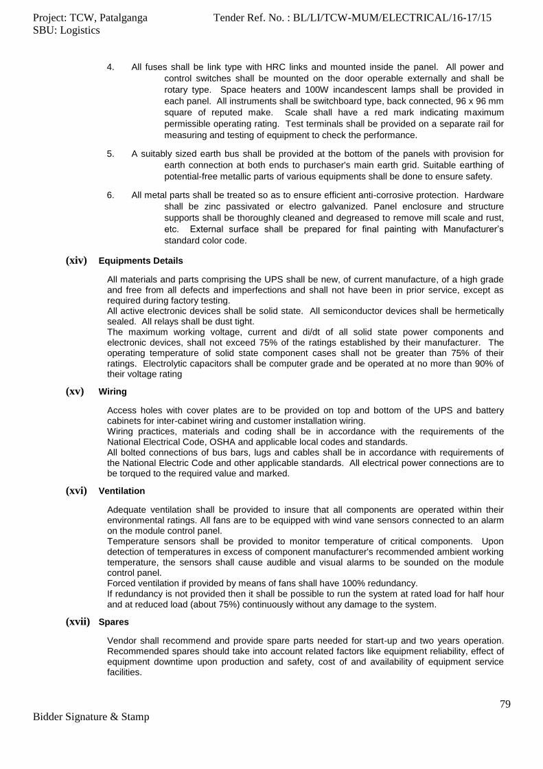
Project: TCW, Patalganga Tender Ref. No. : BL/LI/TCW-MUM/ELECTRICAL/16-17/15
SBU: Logistics
79
Bidder Signature & Stamp
4. All fuses shall be link type with HRC links and mounted inside the panel. All power and
control switches shall be mounted on the door operable externally and shall be
rotary type. Space heaters and 100W incandescent lamps shall be provided in
each panel. All instruments shall be switchboard type, back connected, 96 x 96 mm
square of reputed make. Scale shall have a red mark indicating maximum
permissible operating rating. Test terminals shall be provided on a separate rail for
measuring and testing of equipment to check the performance.
5. A suitably sized earth bus shall be provided at the bottom of the panels with provision for
earth connection at both ends to purchaser's main earth grid. Suitable earthing of
potential-free metallic parts of various equipments shall be done to ensure safety.
6. All metal parts shall be treated so as to ensure efficient anti-corrosive protection. Hardware
shall be zinc passivated or electro galvanized. Panel enclosure and structure
supports shall be thoroughly cleaned and degreased to remove mill scale and rust,
etc. External surface shall be prepared for final painting with Manufacturer’s
standard color code.
(xiv) Equipments Details
All materials and parts comprising the UPS shall be new, of current manufacture, of a high grade and free from all defects and imperfections and shall not have been in prior service, except as required during factory testing. All active electronic devices shall be solid state. All semiconductor devices shall be hermetically sealed. All relays shall be dust tight. The maximum working voltage, current and di/dt of all solid state power components and electronic devices, shall not exceed 75% of the ratings established by their manufacturer. The operating temperature of solid state component cases shall not be greater than 75% of their ratings. Electrolytic capacitors shall be computer grade and be operated at no more than 90% of their voltage rating
(xv) Wiring
Access holes with cover plates are to be provided on top and bottom of the UPS and battery cabinets for inter-cabinet wiring and customer installation wiring. Wiring practices, materials and coding shall be in accordance with the requirements of the National Electrical Code, OSHA and applicable local codes and standards. All bolted connections of bus bars, lugs and cables shall be in accordance with requirements of the National Electric Code and other applicable standards. All electrical power connections are to be torqued to the required value and marked.
(xvi) Ventilation
Adequate ventilation shall be provided to insure that all components are operated within their environmental ratings. All fans are to be equipped with wind vane sensors connected to an alarm on the module control panel. Temperature sensors shall be provided to monitor temperature of critical components. Upon detection of temperatures in excess of component manufacturer's recommended ambient working temperature, the sensors shall cause audible and visual alarms to be sounded on the module control panel. Forced ventilation if provided by means of fans shall have 100% redundancy. If redundancy is not provided then it shall be possible to run the system at rated load for half hour and at reduced load (about 75%) continuously without any damage to the system.
(xvii) Spares
Vendor shall recommend and provide spare parts needed for start-up and two years operation. Recommended spares should take into account related factors like equipment reliability, effect of equipment downtime upon production and safety, cost of and availability of equipment service facilities.

Project: TCW, Patalganga Tender Ref. No. : BL/LI/TCW-MUM/ELECTRICAL/16-17/15
SBU: Logistics
80
Bidder Signature & Stamp
All spare parts furnished by vendor shall be wrapped and packed so that they will be presented in original as new condition under the normal conditions of storage to be anticipated and shall be properly taped and coded so that later identification as to intended equipment usage will be facilitated. They shall be packaged separately, clearly marked as spare parts and shipped at the same time as the equipment. Packing list shall be furnished so that the parts can be handled without uncrating, if desired.
(xviii) Inspection and Testing
The Battery shall be subject to inspection by Client's representative. Manufacturer shall furnish to inspectors all requested information concerning the supply. Battery shall be tested as per relevant IS and test certificates shall be furnished before dispatch. The UPS System will be tested in the presence of Client's representative. The following tests shall apply:
1. Full load heat run for eight hours (unit rate to be furnished separately).
2. Current forcing test.
3. Recording of time for mains to inverter changeover and vice-versa.
4. Recording of 1/2 load change transient.
5. Recording of full load change transient.
6. Functional Tests.
Detailed inspection will be performed to ascertain that the data sheet and other contractual aspect are complied with the earthing system must be inspected for robustness and continuity.
24. Lightning Protection
(i) The plant and structures shall be protected against lightning in accordance with requirements of IS-
2309.
(ii) Air terminal rods shall be provided at the top most points of all buildings and structures. Roof
conductors shall be run at not more than 18 meters from each other on top of the buildings and
interconnected at intervals of not more than 18 meters. Hot dip galvanized 25 x 3 mm G.I. strips
shall be used for horizontal air termination. Whenever specified in the BOQ or layout drawing, Early
streamer type lightning protection of reputed make & type subject to owner/ consultant approval
shall be used. Installation procedures shall be approved by Owner/ Consultant prior to the start of
work.
(iii) Down comers shall be installed at every 30 meters of the periphery of the buildings and structures
and connected to separate earthing pits. Each down comer shall be provided with one earthing pit.
Each down comer shall be provided with a test link for testing the installation. Portion at the
conductor below ground shall be painted with bituminous paint.
(iv) The sizes and material of lightning conductors shall be as follows unless otherwise specified in
Specific Requirements.
Roof Conductors Down Comers
a) Copper 20 x 3 mm 32 x 6 mm
b) G I 20 x 3 mm 32 x 6 mm
(v) The down comer shall be cleated to the wall or columns at intervals of 300 mm using G.I. clamps.
All joints in the conductors shall be welded. Welding joints shall be painted with two coats of
Bitumen.
(vi) Each air terminal rod shall have 150 mm dia GI or 75 mm dia copper sphere with 5 nos. 150 mm
long conical GI / Copper spikes. The spikes shall be screwed and welded / brazed to the sphere.
The whole assembly shall be fixed to a GI rod of not less than 50 mm nominal bore by means of
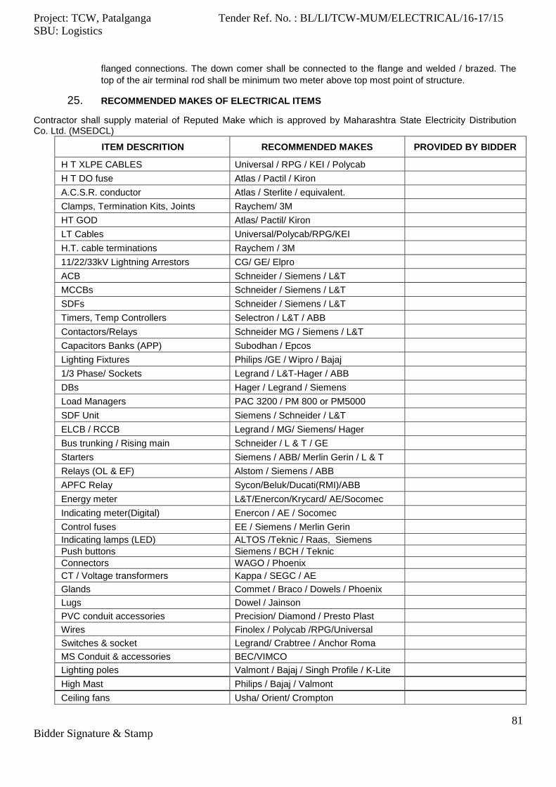
Project: TCW, Patalganga Tender Ref. No. : BL/LI/TCW-MUM/ELECTRICAL/16-17/15
SBU: Logistics
81
Bidder Signature & Stamp
flanged connections. The down comer shall be connected to the flange and welded / brazed. The
top of the air terminal rod shall be minimum two meter above top most point of structure.
25. RECOMMENDED MAKES OF ELECTRICAL ITEMS
Contractor shall supply material of Reputed Make which is approved by Maharashtra State Electricity Distribution Co. Ltd. (MSEDCL)
ITEM DESCRITION RECOMMENDED MAKES PROVIDED BY BIDDER
H T XLPE CABLES Universal / RPG / KEI / Polycab
H T DO fuse Atlas / Pactil / Kiron
A.C.S.R. conductor Atlas / Sterlite / equivalent.
Clamps, Termination Kits, Joints Raychem/ 3M
HT GOD Atlas/ Pactil/ Kiron
LT Cables Universal/Polycab/RPG/KEI
H.T. cable terminations Raychem / 3M
11/22/33kV Lightning Arrestors CG/ GE/ Elpro
ACB Schneider / Siemens / L&T
MCCBs Schneider / Siemens / L&T
SDFs Schneider / Siemens / L&T
Timers, Temp Controllers Selectron / L&T / ABB
Contactors/Relays Schneider MG / Siemens / L&T
Capacitors Banks (APP) Subodhan / Epcos
Lighting Fixtures Philips /GE / Wipro / Bajaj
1/3 Phase/ Sockets Legrand / L&T-Hager / ABB
DBs Hager / Legrand / Siemens
Load Managers PAC 3200 / PM 800 or PM5000
SDF Unit Siemens / Schneider / L&T
ELCB / RCCB Legrand / MG/ Siemens/ Hager
Bus trunking / Rising main Schneider / L & T / GE
Starters Siemens / ABB/ Merlin Gerin / L & T
Relays (OL & EF) Alstom / Siemens / ABB
APFC Relay Sycon/Beluk/Ducati(RMI)/ABB
Energy meter L&T/Enercon/Krycard/ AE/Socomec
Indicating meter(Digital) Enercon / AE / Socomec
Control fuses EE / Siemens / Merlin Gerin
Indicating lamps (LED) ALTOS /Teknic / Raas, Siemens
Push buttons Siemens / BCH / Teknic
Connectors WAGO / Phoenix
CT / Voltage transformers Kappa / SEGC / AE
Glands Commet / Braco / Dowels / Phoenix
Lugs Dowel / Jainson
PVC conduit accessories Precision/ Diamond / Presto Plast
Wires Finolex / Polycab /RPG/Universal
Switches & socket Legrand/ Crabtree / Anchor Roma
MS Conduit & accessories BEC/VIMCO
Lighting poles Valmont / Bajaj / Singh Profile / K-Lite
High Mast Philips / Bajaj / Valmont
Ceiling fans Usha/ Orient/ Crompton
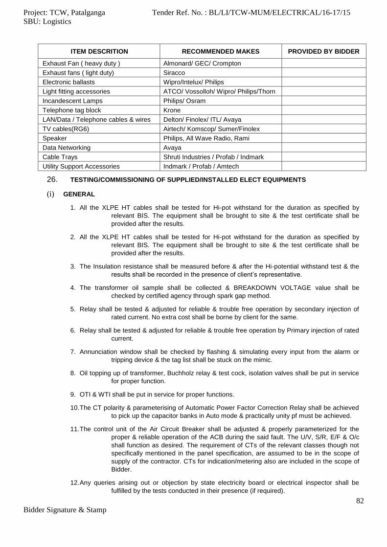
Project: TCW, Patalganga Tender Ref. No. : BL/LI/TCW-MUM/ELECTRICAL/16-17/15
SBU: Logistics
82
Bidder Signature & Stamp
ITEM DESCRITION RECOMMENDED MAKES PROVIDED BY BIDDER
Exhaust Fan ( heavy duty ) Almonard/ GEC/ Crompton
Exhaust fans ( light duty) Siracco
Electronic ballasts Wipro/Intelux/ Philips
Light fitting accessories ATCO/ Vossolloh/ Wipro/ Philips/Thorn
Incandescent Lamps Philips/ Osram
Telephone tag block Krone
LAN/Data / Telephone cables & wires Delton/ Finolex/ ITL/ Avaya
TV cables(RG6) Airtech/ Komscop/ Sumer/Finolex
Speaker Philips, All Wave Radio, Rami
Data Networking Avaya
Cable Trays Shruti Industries / Profab / Indmark
Utility Support Accessories Indmark / Profab / Amtech
26. TESTING/COMMISSIONING OF SUPPLIED/INSTALLED ELECT EQUIPMENTS
(i) GENERAL
1. All the XLPE HT cables shall be tested for Hi-pot withstand for the duration as specified by
relevant BIS. The equipment shall be brought to site & the test certificate shall be
provided after the results.
2. All the XLPE HT cables shall be tested for Hi-pot withstand for the duration as specified by
relevant BIS. The equipment shall be brought to site & the test certificate shall be
provided after the results.
3. The Insulation resistance shall be measured before & after the Hi-potential withstand test & the
results shall be recorded in the presence of client’s representative.
4. The transformer oil sample shall be collected & BREAKDOWN VOLTAGE value shall be
checked by certified agency through spark gap method.
5. Relay shall be tested & adjusted for reliable & trouble free operation by secondary injection of
rated current. No extra cost shall be borne by client for the same.
6. Relay shall be tested & adjusted for reliable & trouble free operation by Primary injection of rated
current.
7. Annunciation window shall be checked by flashing & simulating every input from the alarm or
tripping device & the tag list shall be stuck on the mimic.
8. Oil topping up of transformer, Buchholz relay & test cock, isolation valves shall be put in service
for proper function.
9. OTI & WTI shall be put in service for proper functions.
10. The CT polarity & parameterising of Automatic Power Factor Correction Relay shall be achieved
to pick up the capacitor banks in Auto mode & practically unity pf must be achieved.
11. The control unit of the Air Circuit Breaker shall be adjusted & properly parameterized for the
proper & reliable operation of the ACB during the said fault. The U/V, S/R, E/F & O/c
shall function as desired. The requirement of CTs of the relevant classes though not
specifically mentioned in the panel specification, are assumed to be in the scope of
supply of the contractor. CTs for indication/metering also are included in the scope of
Bidder.
12. Any queries arising out or objection by state electricity board or electrical inspector shall be
fulfilled by the tests conducted in their presence (if required).

Project: TCW, Patalganga Tender Ref. No. : BL/LI/TCW-MUM/ELECTRICAL/16-17/15
SBU: Logistics
83
Bidder Signature & Stamp
13. A pre-commissioning protocol for each panel shall be submitted by the contractor to the
consultant before charging the panel for No load or On load trials.
14. Gas pressure, functional tests, spring charging, auxiliary contact supply and releases to be
checked before installation for Vacuum Circuit Breakers.
15. The electrical installation and the various electrical equipment shall be tested and certified test
results shall be furnished as directed by CONSULTANTS/Client.
16. The testing of all electrical equipment as well as the system as a whole shall be carried out to
ensure that the equipment and its components are in satisfactory condition and will
successfully perform its functional requirements.
17. Tests in accordance with the specified or applicable latest relevant Indian Standards Codes of
Practice or regulations shall be carried out by the contractor, who shall provide at his
own expenses all appliances, instruments, labour and other facilities required for such
tests.
18. Before each test on any apparatus, the contractor shall obtain the permission from the
CONSULTANTS/Client and all tests shall be conducted in the presence of duly
authorised representative. Records of each test shall be prepared immediately after
the test and this record shall be signed by contractor's representative conducting the
test and CONSULTANTS/Client. Six Copies of this record shall be handed over to
CONSULTANTS/Client.
19. All tests shall be carried out by qualified testing personnel.
20. Before starting the testing of various equipment, the contractor shall ensure that the erection
works have been carried out and completed in all respects.
21. The contractor must ensure that oil immersed apparatus; dash-pots, etc. are filled with correct
type of oil up to correct level before testing the apparatus.
22. The contractor must ensure that all safety gadgets are in position and must ensure all the
earthing connections are proper and tight.
23. The contractor shall take all safety precautions as per standard code of practice to prevent
danger to the testing and other personnel in the vicinity of testing equipment.
24. The contractor must put up appropriate warning boards on all the equipment under test.
25. The contractor shall cordon off the area where high voltage tests are in progress and put up
danger boards on all the sides warning the persons.
26. While conducting the various tests, the contractor shall take suitable precautions to prevent
damage to the various meters instruments and instrument transformers.
(ii) SWITCHGEAR
1. Pre-commissioning Check List
The testing will be carried out as per testing schedule. However, before commissioning any switchgear panel, circuit breaker, motor starter, etc., the following points must be checked and ensured for safe energising of the switchboard.
2. The erection of equipment to be commissioned is complete in all respect with its auxiliaries and
all other mountings including earthing. Openings in floor within and outside panels
have been sealed off. All cover and door gaskets are intact to make enclosure vermin
proof.
3. All the metering instruments have been checked and calibrated. Indicating lamps are healthy
and are in position. All power and control fuses are of proper rating and show
continuity.
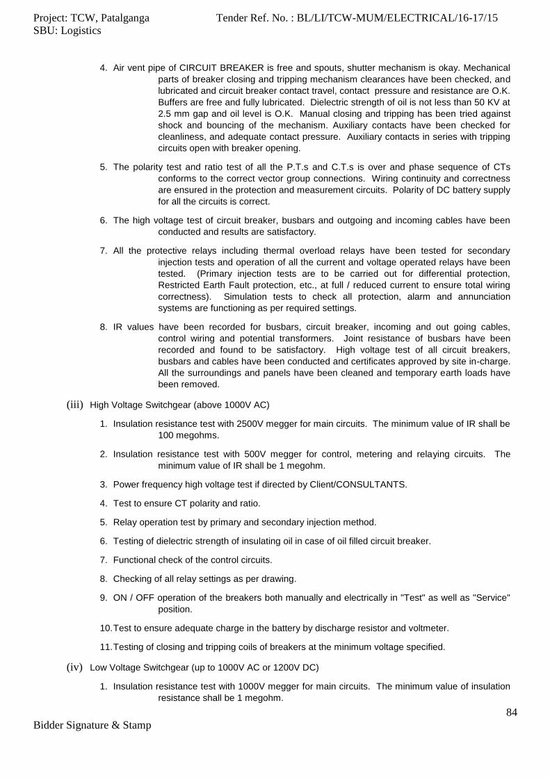
Project: TCW, Patalganga Tender Ref. No. : BL/LI/TCW-MUM/ELECTRICAL/16-17/15
SBU: Logistics
84
Bidder Signature & Stamp
4. Air vent pipe of CIRCUIT BREAKER is free and spouts, shutter mechanism is okay. Mechanical
parts of breaker closing and tripping mechanism clearances have been checked, and
lubricated and circuit breaker contact travel, contact pressure and resistance are O.K.
Buffers are free and fully lubricated. Dielectric strength of oil is not less than 50 KV at
2.5 mm gap and oil level is O.K. Manual closing and tripping has been tried against
shock and bouncing of the mechanism. Auxiliary contacts have been checked for
cleanliness, and adequate contact pressure. Auxiliary contacts in series with tripping
circuits open with breaker opening.
5. The polarity test and ratio test of all the P.T.s and C.T.s is over and phase sequence of CTs
conforms to the correct vector group connections. Wiring continuity and correctness
are ensured in the protection and measurement circuits. Polarity of DC battery supply
for all the circuits is correct.
6. The high voltage test of circuit breaker, busbars and outgoing and incoming cables have been
conducted and results are satisfactory.
7. All the protective relays including thermal overload relays have been tested for secondary
injection tests and operation of all the current and voltage operated relays have been
tested. (Primary injection tests are to be carried out for differential protection,
Restricted Earth Fault protection, etc., at full / reduced current to ensure total wiring
correctness). Simulation tests to check all protection, alarm and annunciation
systems are functioning as per required settings.
8. IR values have been recorded for busbars, circuit breaker, incoming and out going cables,
control wiring and potential transformers. Joint resistance of busbars have been
recorded and found to be satisfactory. High voltage test of all circuit breakers,
busbars and cables have been conducted and certificates approved by site in-charge.
All the surroundings and panels have been cleaned and temporary earth loads have
been removed.
(iii) High Voltage Switchgear (above 1000V AC)
1. Insulation resistance test with 2500V megger for main circuits. The minimum value of IR shall be
100 megohms.
2. Insulation resistance test with 500V megger for control, metering and relaying circuits. The
minimum value of IR shall be 1 megohm.
3. Power frequency high voltage test if directed by Client/CONSULTANTS.
4. Test to ensure CT polarity and ratio.
5. Relay operation test by primary and secondary injection method.
6. Testing of dielectric strength of insulating oil in case of oil filled circuit breaker.
7. Functional check of the control circuits.
8. Checking of all relay settings as per drawing.
9. ON / OFF operation of the breakers both manually and electrically in "Test" as well as "Service"
position.
10. Test to ensure adequate charge in the battery by discharge resistor and voltmeter.
11. Testing of closing and tripping coils of breakers at the minimum voltage specified.
(iv) Low Voltage Switchgear (up to 1000V AC or 1200V DC)
1. Insulation resistance test with 1000V megger for main circuits. The minimum value of insulation
resistance shall be 1 megohm.

Project: TCW, Patalganga Tender Ref. No. : BL/LI/TCW-MUM/ELECTRICAL/16-17/15
SBU: Logistics
85
Bidder Signature & Stamp
2. Insulation resistance test with 500V megger for control, metering and relaying circuits. The
minimum value of insulation resistance shall be 1 megohm.
3. Relay operation test by secondary injection method.
4. Functional test of the control circuits.
5. Checking of settings of all relays / release as per drawings.
6. ON / OFF operation of breakers both manually and electrically in "Test" as well as "Service"
positions.
7. Checking tightness of busbar & switchgear operating handle.
(v) TRANSFORMERS
1. Insulation tests between phases and phase to earth shall be conducted.
2. Three samples of oils from each transformer shall be taken and tested for dielectric strength.
3. The silica gel of the breather shall be tested for the dryness; if necessary, it shall be reactivated.
4. Operation of Buchholz Relay, temperature relay and alarm contacts shall be checked.
5. Ratio and polarity tests shall be conducted and recorded and the tap shall be set to appropriate
position and locked.
6. Following tests shall be carried out:
HV test, if directed by Owner, shall be in accordance with IS-2026 (latest edition).
Insulation resistance to earth of each winding to earth using 1000V megger for
winding up to 1000V and 2500V megger for winding of higher voltages (IS-2026 :
17.9).
Oil test Should (IS-335:1993) and withstand 50 KV (IS-6792-1992) at 2.5 mm gap.
Polarity and phasing check (IS-2886:1991:12.2).
Buchholz relay operation test (by compressed air or other suitable means approved
by employer).
Alarm checks for Buchholz & Oil Temperature.
DC winding resistance measurement at various taps if directed by
CONSULTANTS/Client.
Vector group Test if directed by CONSULTANTS/Client.
7. Observations after Commissioning
The inrush of magnetising current and no load current.
Alarm if any or any relay flag has operated.
Voltage and current on all the three phases.
Transformer hum or abnormal noise.
Circulation of oil and leakages.
Record current, voltage, cooling air temperature, winding temperature and oil
temperature readings, hourly for 24 hours.
Cable and boxes for any overheating.
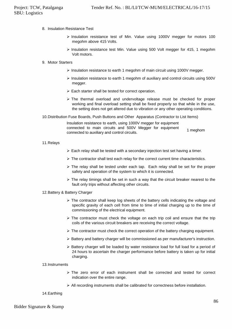
Project: TCW, Patalganga Tender Ref. No. : BL/LI/TCW-MUM/ELECTRICAL/16-17/15
SBU: Logistics
86
Bidder Signature & Stamp
8. Insulation Resistance Test
Insulation resistance test of Min. Value using 1000V megger for motors 100
megohm above 415 Volts.
Insulation resistance test Min. Value using 500 Volt megger for 415, 1 megohm
Volt motors.
9. Motor Starters
Insulation resistance to earth 1 megohm of main circuit using 1000V megger.
Insulation resistance to earth 1 megohm of auxiliary and control circuits using 500V
megger.
Each starter shall be tested for correct operation.
The thermal overload and undervoltage release must be checked for proper
working and final overload setting shall be fixed properly so that while in the use,
the setting does not get altered due to vibration or any other operating conditions.
10. Distribution Fuse Boards, Push Buttons and Other Apparatus (Contractor to List Items)
Insulation resistance to earth, using 1000V megger for equipment
connected to main circuits and 500V Megger for equipment
connected to auxiliary and control circuits. 1 meghom
11. Relays
Each relay shall be tested with a secondary injection test set having a timer.
The contractor shall test each relay for the correct current time characteristics.
The relay shall be tested under each tap. Each relay shall be set for the proper
safety and operation of the system to which it is connected.
The relay timings shall be set in such a way that the circuit breaker nearest to the
fault only trips without affecting other circuits.
12. Battery & Battery Charger
The contractor shall keep log sheets of the battery cells indicating the voltage and
specific gravity of each cell from time to time of initial charging up to the time of
commissioning of the electrical equipment.
The contractor must check the voltage on each trip coil and ensure that the trip
coils of the various circuit breakers are receiving the correct voltage.
The contractor must check the correct operation of the battery charging equipment.
Battery and battery charger will be commissioned as per manufacturer's instruction.
Battery charger will be loaded by water resistance load for full load for a period of
24 hours to ascertain the charger performance before battery is taken up for initial
charging.
13. Instruments
The zero error of each instrument shall be corrected and tested for correct
indication over the entire range.
All recording instruments shall be calibrated for correctness before installation.
14. Earthing
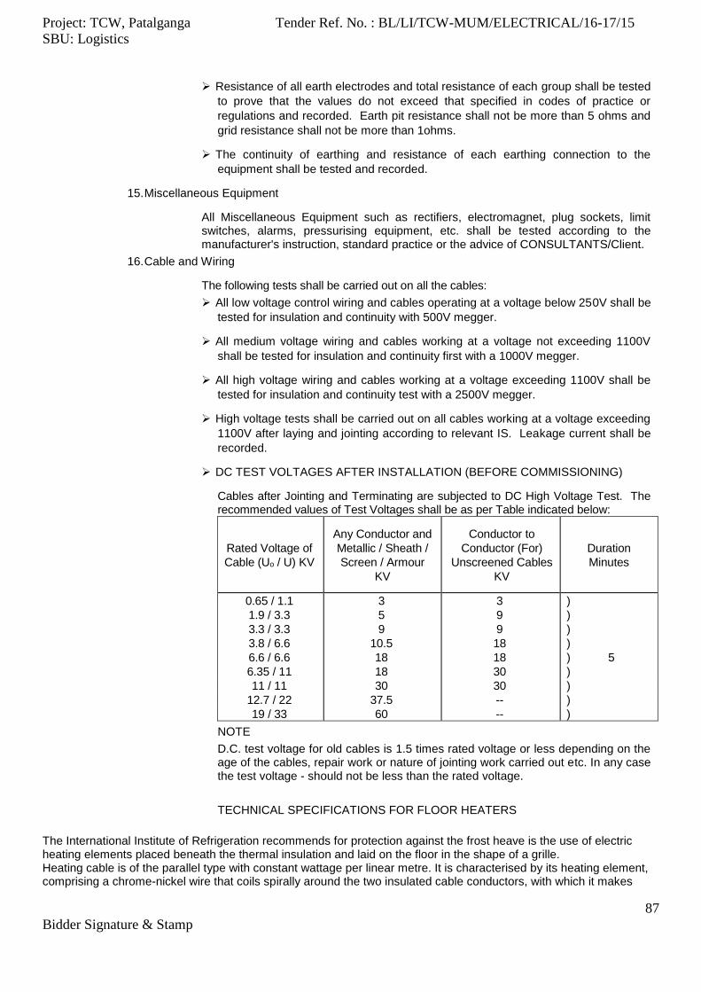
Project: TCW, Patalganga Tender Ref. No. : BL/LI/TCW-MUM/ELECTRICAL/16-17/15
SBU: Logistics
87
Bidder Signature & Stamp
Resistance of all earth electrodes and total resistance of each group shall be tested
to prove that the values do not exceed that specified in codes of practice or
regulations and recorded. Earth pit resistance shall not be more than 5 ohms and
grid resistance shall not be more than 1ohms.
The continuity of earthing and resistance of each earthing connection to the
equipment shall be tested and recorded.
15. Miscellaneous Equipment
All Miscellaneous Equipment such as rectifiers, electromagnet, plug sockets, limit switches, alarms, pressurising equipment, etc. shall be tested according to the manufacturer's instruction, standard practice or the advice of CONSULTANTS/Client.
16. Cable and Wiring
The following tests shall be carried out on all the cables:
All low voltage control wiring and cables operating at a voltage below 250V shall be
tested for insulation and continuity with 500V megger.
All medium voltage wiring and cables working at a voltage not exceeding 1100V
shall be tested for insulation and continuity first with a 1000V megger.
All high voltage wiring and cables working at a voltage exceeding 1100V shall be
tested for insulation and continuity test with a 2500V megger.
High voltage tests shall be carried out on all cables working at a voltage exceeding
1100V after laying and jointing according to relevant IS. Leakage current shall be
recorded.
DC TEST VOLTAGES AFTER INSTALLATION (BEFORE COMMISSIONING)
Cables after Jointing and Terminating are subjected to DC High Voltage Test. The recommended values of Test Voltages shall be as per Table indicated below:
Rated Voltage of
Cable (Uo / U) KV
Any Conductor and
Metallic / Sheath /
Screen / Armour
KV
Conductor to
Conductor (For)
Unscreened Cables
KV
Duration
Minutes
0.65 / 1.1 3 3 )
1.9 / 3.3 5 9 )
3.3 / 3.3 9 9 )
3.8 / 6.6 10.5 18 )
6.6 / 6.6 18 18 ) 5
6.35 / 11 18 30 )
11 / 11 30 30 )
12.7 / 22 37.5 -- )
19 / 33 60 -- )
NOTE
D.C. test voltage for old cables is 1.5 times rated voltage or less depending on the age of the cables, repair work or nature of jointing work carried out etc. In any case the test voltage - should not be less than the rated voltage.
TECHNICAL SPECIFICATIONS FOR FLOOR HEATERS
The International Institute of Refrigeration recommends for protection against the frost heave is the use of electric heating elements placed beneath the thermal insulation and laid on the floor in the shape of a grille. Heating cable is of the parallel type with constant wattage per linear metre. It is characterised by its heating element, comprising a chrome-nickel wire that coils spirally around the two insulated cable conductors, with which it makes
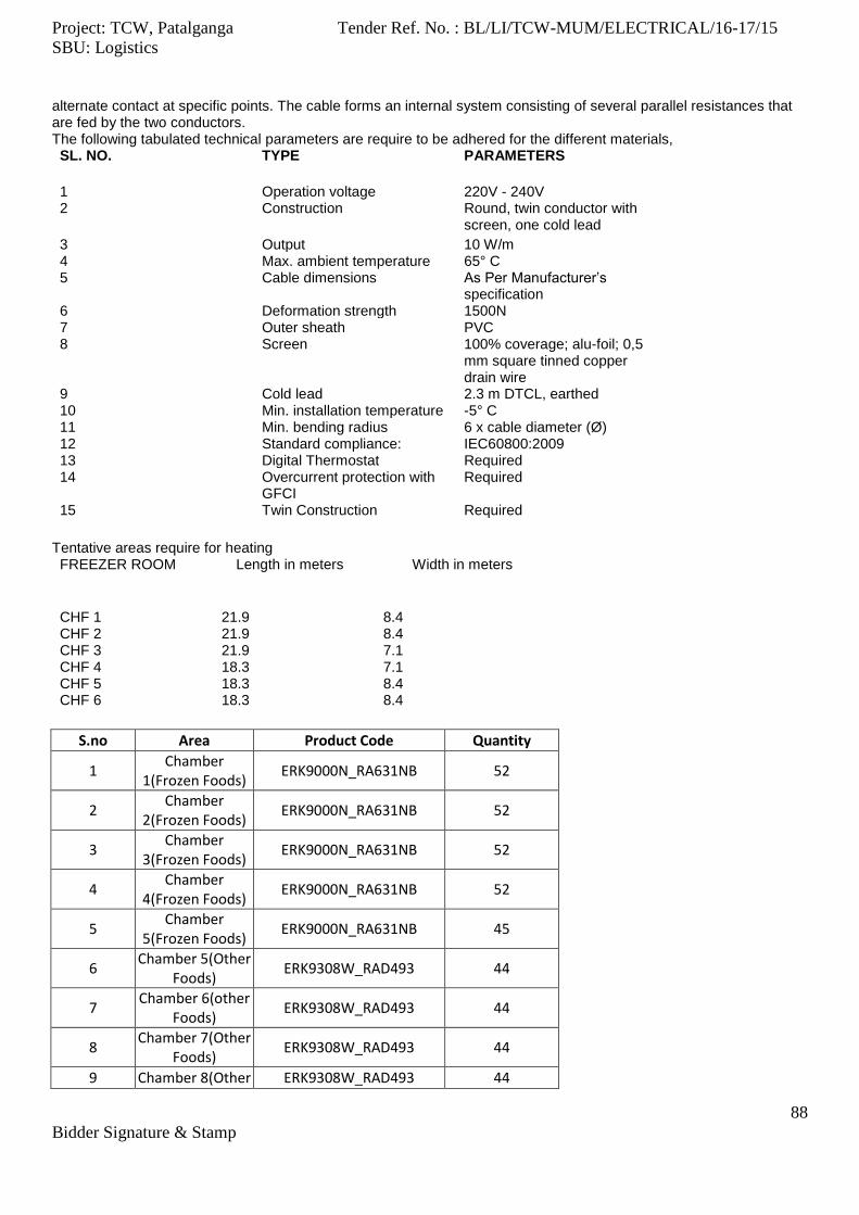
Project: TCW, Patalganga Tender Ref. No. : BL/LI/TCW-MUM/ELECTRICAL/16-17/15
SBU: Logistics
88
Bidder Signature & Stamp
alternate contact at specific points. The cable forms an internal system consisting of several parallel resistances that are fed by the two conductors. The following tabulated technical parameters are require to be adhered for the different materials, SL. NO. TYPE PARAMETERS
1 Operation voltage 220V - 240V 2 Construction Round, twin conductor with
screen, one cold lead
3 Output 10 W/m 4 Max. ambient temperature 65° C 5 Cable dimensions As Per Manufacturer’s
specification 6 Deformation strength 1500N 7 Outer sheath PVC 8 Screen 100% coverage; alu-foil; 0,5
mm square tinned copper drain wire
9 Cold lead 2.3 m DTCL, earthed 10 Min. installation temperature -5° C 11 Min. bending radius 6 x cable diameter (Ø) 12 Standard compliance: IEC60800:2009 13 Digital Thermostat Required 14 Overcurrent protection with
GFCI Required
15 Twin Construction Required
Tentative areas require for heating FREEZER ROOM Length in meters Width in meters
CHF 1 21.9 8.4 CHF 2 21.9 8.4 CHF 3 21.9 7.1 CHF 4 18.3 7.1 CHF 5 18.3 8.4 CHF 6 18.3 8.4
S.no Area Product Code Quantity
1 Chamber
1(Frozen Foods) ERK9000N_RA631NB 52
2 Chamber
2(Frozen Foods) ERK9000N_RA631NB 52
3 Chamber
3(Frozen Foods) ERK9000N_RA631NB 52
4 Chamber
4(Frozen Foods) ERK9000N_RA631NB 52
5 Chamber
5(Frozen Foods) ERK9000N_RA631NB 45
6 Chamber 5(Other
Foods) ERK9308W_RAD493 44
7 Chamber 6(other
Foods) ERK9308W_RAD493 44
8 Chamber 7(Other
Foods) ERK9308W_RAD493 44
9 Chamber 8(Other ERK9308W_RAD493 44

Project: TCW, Patalganga Tender Ref. No. : BL/LI/TCW-MUM/ELECTRICAL/16-17/15
SBU: Logistics
89
Bidder Signature & Stamp
Foods)
10 Chamber 9(Other
Foods) ERK9308W_RAD493 39
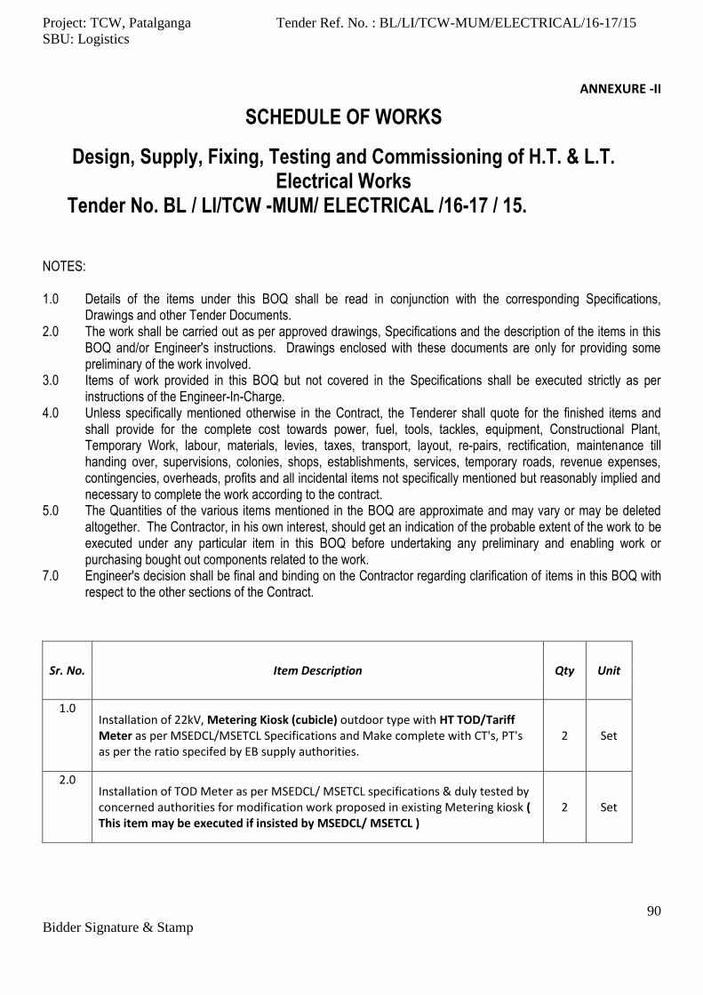
Project: TCW, Patalganga Tender Ref. No. : BL/LI/TCW-MUM/ELECTRICAL/16-17/15
SBU: Logistics
90
Bidder Signature & Stamp
ANNEXURE -II
SCHEDULE OF WORKS
Design, Supply, Fixing, Testing and Commissioning of H.T. & L.T. Electrical Works
Tender No. BL / LI/TCW -MUM/ ELECTRICAL /16-17 / 15.
NOTES: 1.0 Details of the items under this BOQ shall be read in conjunction with the corresponding Specifications,
Drawings and other Tender Documents. 2.0 The work shall be carried out as per approved drawings, Specifications and the description of the items in this
BOQ and/or Engineer's instructions. Drawings enclosed with these documents are only for providing some preliminary of the work involved.
3.0 Items of work provided in this BOQ but not covered in the Specifications shall be executed strictly as per instructions of the Engineer-In-Charge.
4.0 Unless specifically mentioned otherwise in the Contract, the Tenderer shall quote for the finished items and shall provide for the complete cost towards power, fuel, tools, tackles, equipment, Constructional Plant, Temporary Work, labour, materials, levies, taxes, transport, layout, repairs, rectification, maintenance till handing over, supervisions, colonies, shops, establishments, services, temporary roads, revenue expenses, contingencies, overheads, profits and all incidental items not specifically mentioned but reasonably implied and necessary to complete the work according to the contract.
5.0 The Quantities of the various items mentioned in the BOQ are approximate and may vary or may be deleted altogether. The Contractor, in his own interest, should get an indication of the probable extent of the work to be executed under any particular item in this BOQ before undertaking any preliminary and enabling work or purchasing bought out components related to the work.
7.0 Engineer's decision shall be final and binding on the Contractor regarding clarification of items in this BOQ with respect to the other sections of the Contract.
Sr. No. Item Description Qty Unit
1.0 Installation of 22kV, Metering Kiosk (cubicle) outdoor type with HT TOD/Tariff Meter as per MSEDCL/MSETCL Specifications and Make complete with CT's, PT's as per the ratio specifed by EB supply authorities.
2 Set
2.0 Installation of TOD Meter as per MSEDCL/ MSETCL specifications & duly tested by concerned authorities for modification work proposed in existing Metering kiosk ( This item may be executed if insisted by MSEDCL/ MSETCL )
2 Set
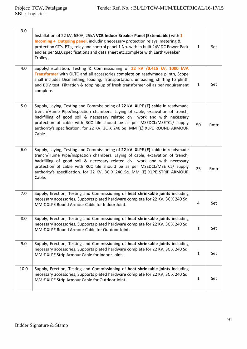
Project: TCW, Patalganga Tender Ref. No. : BL/LI/TCW-MUM/ELECTRICAL/16-17/15
SBU: Logistics
91
Bidder Signature & Stamp
3.0 Installation of 22 kV, 630A, 25kA VCB Indoor Breaker Panel (Extendable) with 1 Incoming + Outgoing panel, including necessary protection relays, metering & protection CT's, PT's, relay and control panel 1 No. with in built 24V DC Power Pack and as per SLD, specifications and data sheet etc.complete with Earth/Breaker Trolley.
1 Set
4.0 Supply,Installation, Testing & Commissioning of 22 kV /0.415 kV, 1000 kVA Transformer with OLTC and all accessories complete on readymade plinth, Scope shall includes Dismantling, loading, Transportation, unloading, shifting to plinth and BDV test, Filtration & topping-up of fresh transformer oil as per requirement complete.
1 Set
5.0 Supply, Laying, Testing and Commissioning of 22 kV XLPE (E) cable in readymade trench/Hume Pipe/Inspection chambers. Laying of cable, excavation of trench, backfilling of good soil & necessary related civil work and with necessary protection of cable with RCC tile should be as per MSEDCL/MSETCL/ supply authority's specification. for 22 KV, 3C X 240 Sq. MM (E) XLPE ROUND ARMOUR Cable.
50 Rmtr
6.0 Supply, Laying, Testing and Commissioning of 22 kV XLPE (E) cable in readymade trench/Hume Pipe/Inspection chambers. Laying of cable, excavation of trench, backfilling of good soil & necessary related civil work and with necessary protection of cable with RCC tile should be as per MSEDCL/MSETCL/ supply authority's specification. for 22 KV, 3C X 240 Sq. MM (E) XLPE STRIP ARMOUR Cable.
25 Rmtr
7.0 Supply, Erection, Testing and Commissioning of heat shrinkable joints including necessary accessories, Supports plated hardware complete for 22 KV, 3C X 240 Sq. MM € XLPE Round Armour Cable for Indoor Joint. 4 Set
8.0 Supply, Erection, Testing and Commissioning of heat shrinkable joints including necessary accessories, Supports plated hardware complete for 22 KV, 3C X 240 Sq. MM € XLPE Round Armour Cable for Outdoor Joint. 1 Set
9.0 Supply, Erection, Testing and Commissioning of heat shrinkable joints including necessary accessories, Supports plated hardware complete for 22 KV, 3C X 240 Sq. MM € XLPE Strip Armour Cable for Indoor Joint. 1 Set
10.0 Supply, Erection, Testing and Commissioning of heat shrinkable joints including necessary accessories, Supports plated hardware complete for 22 KV, 3C X 240 Sq. MM € XLPE Strip Armour Cable for Outdoor Joint. 1 Set

Project: TCW, Patalganga Tender Ref. No. : BL/LI/TCW-MUM/ELECTRICAL/16-17/15
SBU: Logistics
92
Bidder Signature & Stamp
11.0 Excavation of cable trenches upto a depth of 1500mm refilling and reinstating the trenches and removing excess soil after proper 4" sand bedding/ coushioning above & below cables with Bricks as per MSEDCL/MSETCL specifications & IS standards in Hard Rocks, Murrum etc., complete.
75 Rmtr
12.0 Providing and fixing cable route markers for HT Cables of oval cast iron with 350mm, Φ 20mm GI pipe support cast in 150x150x150mm PCC Block 15 Nos.
13.0 Supply,Installation of RCC Hume pipes with sand bedding & excavation 750 mm below ground complete for road crossing, cable laying etc of Φ 300 MM RCC Hume Pipe.
200 Rmtr
14.0 Supply and Installation of 4.5 Kg fire extinguisher - DCP Type as per IS : 15683 2 Nos.
15.0 Supply and Inatallation of 9.5 Kg fire extinguisher - CO2 Type as per IS : 15683 2 Nos.
16.0 Supply and Installation of Fire Buckets stand with 4 No. of Buckets filled with Fine Sand as per IS 2546: 1974 2 Set
17.0 Supply and Laying of 22kV Grade, 1Mtr. wide Rubber Mat as per Tender Specifications & as per IS : 2006 5 Rmtr
18.0 Supply and Laying of 1.1kV Grade, 1Mtr. wide Rubber Mat as per Tender Specifications 15 Rmtr
19.0 Supplying of Hand Gloves of 22 KV rated 2 Set
20.0 Supply and Fixing of Laminated Danger Boards "22 KV", ''400V '' of 300mm x 225mm Size . 5 Nos.
21.0 Supply and Fixing of First Aid Box - (Medium Kit) consisting of the followings, 1.Emergency dental kit, 2.Sterile needles and surgical blades, 3-Splints – SAM and air splints, 4-Quick Clot Gauze, 5-Grooming and cleaning tools – Fingernail clippers, soap, Antiseptic wipes, 6-Tweezers, 7-Scissors, 8-Disposable thermometers, 9-Disposable gloves, 10-Sterile eyewash & eye dressings, 11-Sunblock, 12-Vaseline, 13-Burn creams and dressings, 14-Medical manuals and basic first aid instructions
2 Set
22.0 Supply and Fixing of First Aid Treatment Chart of standard size. Each set should have language of Marathi, Hindi & English. 2 Set
23.0 Supply, Installation, testing and commissioning of Main L.T. panel boards Compartmental cubicle type, freestanding with appropriate cable entries, & manufactured based on IS 8623, AEPPL specifications and single line diagrams. Scope shall include unloading, shifting, unpacking, Section assembly from storage place to desired Installation. Please refer Technical Specifications and Single Line Diagram for details.
1 Set
24.0 Supply, Installation, testing and commissioning of RTPFC panel (550 KVAR) Compartmental cubicle type, freestanding with appropriate cable entries, & manufactured based on IS 8623, Technical Specifications and single line diagrams. Scope shall include unloading, shifting, unpacking, Section assembly from storage place to desired Installation. Please refer Technical Specifications and Single Line Diagram for details.
1 Set
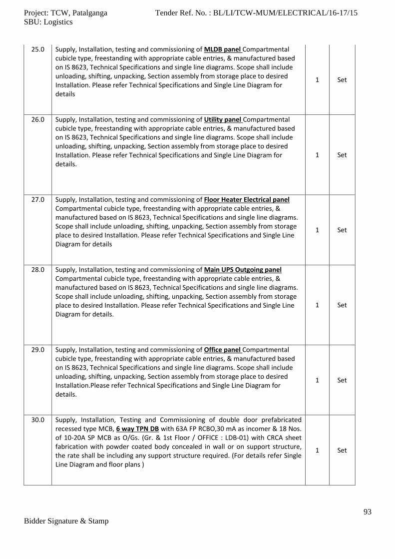
Project: TCW, Patalganga Tender Ref. No. : BL/LI/TCW-MUM/ELECTRICAL/16-17/15
SBU: Logistics
93
Bidder Signature & Stamp
25.0 Supply, Installation, testing and commissioning of MLDB panel Compartmental cubicle type, freestanding with appropriate cable entries, & manufactured based on IS 8623, Technical Specifications and single line diagrams. Scope shall include unloading, shifting, unpacking, Section assembly from storage place to desired Installation. Please refer Technical Specifications and Single Line Diagram for details
1 Set
26.0 Supply, Installation, testing and commissioning of Utility panel Compartmental cubicle type, freestanding with appropriate cable entries, & manufactured based on IS 8623, Technical Specifications and single line diagrams. Scope shall include unloading, shifting, unpacking, Section assembly from storage place to desired Installation. Please refer Technical Specifications and Single Line Diagram for details.
1 Set
27.0 Supply, Installation, testing and commissioning of Floor Heater Electrical panel Compartmental cubicle type, freestanding with appropriate cable entries, & manufactured based on IS 8623, Technical Specifications and single line diagrams. Scope shall include unloading, shifting, unpacking, Section assembly from storage place to desired Installation. Please refer Technical Specifications and Single Line Diagram for details
1 Set
28.0 Supply, Installation, testing and commissioning of Main UPS Outgoing panel Compartmental cubicle type, freestanding with appropriate cable entries, & manufactured based on IS 8623, Technical Specifications and single line diagrams. Scope shall include unloading, shifting, unpacking, Section assembly from storage place to desired Installation. Please refer Technical Specifications and Single Line Diagram for details.
1 Set
29.0 Supply, Installation, testing and commissioning of Office panel Compartmental cubicle type, freestanding with appropriate cable entries, & manufactured based on IS 8623, Technical Specifications and single line diagrams. Scope shall include unloading, shifting, unpacking, Section assembly from storage place to desired Installation.Please refer Technical Specifications and Single Line Diagram for details.
1 Set
30.0 Supply, Installation, Testing and Commissioning of double door prefabricated recessed type MCB, 6 way TPN DB with 63A FP RCBO,30 mA as incomer & 18 Nos. of 10-20A SP MCB as O/Gs. (Gr. & 1st Floor / OFFICE : LDB-01) with CRCA sheet fabrication with powder coated body concealed in wall or on support structure, the rate shall be including any support structure required. (For details refer Single Line Diagram and floor plans )
1 Set

Project: TCW, Patalganga Tender Ref. No. : BL/LI/TCW-MUM/ELECTRICAL/16-17/15
SBU: Logistics
94
Bidder Signature & Stamp
31.0 Supply, Installation, Testing and Commissioning of double door prefabricated recessed type MCB, 8way TPN DB with 63A FP MCB as incomer & 24 Nos. of 20A SP MCB as O/Gs. (Gr. & 1st Floor/OFFICE: PDB ) with CRCA sheet fabrication with powder coated body concealed in wall or on support structure, the rate shall be including any support structure required. (For details refer Single Line Diagram and floor plans ).
1 Set
32.0 Supply, Installation, Testing and Commissioning of double door prefabricated recessed type MCB, 4 way TPN DB with 63A TPN MCB as Main incomer & 12 Nos. of 20A SP MCBs as O/Gs. (OFFICE AC DB) with CRCA sheet fabrication with powder coated body concealed in wall or on support structure, the rate shall be including any support structure required. (For details refer Single Line Diagram and floor plans ).
1 Set
33.0 Supply, Installation, Testing and Commissioning of double door prefabricated recessed type MCB, 12 way SPN DB (IP-54) (with 25A DP RCBO,30 mA as incomer & 8 Nos. of 10-20A SP MCB as O/Gs. (ELDB01 to ELDB05 ) with CRCA sheet fabrication with powder coated body concealed in wall or on support structure, the rate shall be including any support structure required. (For details refer Single Line Diagram and floor plans ).
5 Set
34.0 Supply, Installation, Testing and Commissioning of double door prefabricated , 12 way SPN DB (IP-54)with 16A DP RCBO,30 mA as incomer & 8 Nos. of 10-20A SP MCB as O/Gs. (Chamber-1 to Chamber-10 LDB ) with CRCA sheet fabrication with powder coated body concealed in wall or on support structure, the rate shall be including any support structure required. (For details & Single Line Diagram Pl. refer floor plans ).
10 Set
35.0 Supply, Installation, Testing and Commissioning of double door prefabricated recessed type MCB, 12 way SPN DB (IP-54)with 32A DP RCBO,30 mA as incomer & 8 Nos. of 16A DP MCB as O/Gs. ( Emergency Lighting Inverter DB ) with CRCA sheet fabrication with powder coated body concealed in wall or on support structure, the rate shall be including any support structure required. (For details refer Single Line Diagram and floor plans )
1 Set
36.0 Supply, Installation, Testing and Commissioning of double door prefabricated recessed type MCB, 8 Way SPN DB (IP-54)with 40A DP RCBO,100 mA as incomer & 4 Nos. of 16A DP MCB as O/Gs. ( Main UPS DB ) with CRCA sheet fabrication with powder coated body concealed in wall or on support structure, the rate shall be including any support structure required. (For details & Single Line Diagram Pl. refer floor plans )
1 Set
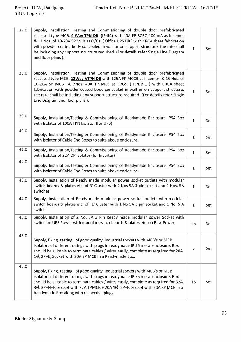
Project: TCW, Patalganga Tender Ref. No. : BL/LI/TCW-MUM/ELECTRICAL/16-17/15
SBU: Logistics
95
Bidder Signature & Stamp
37.0 Supply, Installation, Testing and Commissioning of double door prefabricated recessed type MCB, 4 Way TPN DB (IP-54) with 40A FP RCBO,100 mA as incomer & 12 Nos. of 10-20A SP MCB as O/Gs. ( Office UPS DB ) with CRCA sheet fabrication with powder coated body concealed in wall or on support structure, the rate shall be including any support structure required. (For details refer Single Line Diagram and floor plans ).
1 Set
38.0 Supply, Installation, Testing and Commissioning of double door prefabricated recessed type MCB, 12Way VTPN DB with 125A FP MCCB as incomer & 15 Nos. of 10-20A SP MCB & 7Nos. 40A TP MCB as O/Gs. ( RPDB-1 ) with CRCA sheet fabrication with powder coated body concealed in wall or on support structure, the rate shall be including any support structure required. (For details refer Single Line Diagram and floor plans ).
1 Set
39.0 Supply, Installation,Testing & Commissioning of Readymade Enclosure IP54 Box with Isolator of 100A TPN Isolator (for UPS)
1 Set
40.0 Supply, Installation,Testing & Commissioning of Readymade Enclosure IP54 Box with Isolator of Cable End Boxes to suite above enclosure.
1 Set
41.0 Supply, Installation,Testing & Commissioning of Readymade Enclosure IP54 Box with Isolator of 32A DP Isolator (for Inverter)
1 Set
42.0 Supply, Installation,Testing & Commissioning of Readymade Enclosure IP54 Box with Isolator of Cable End Boxes to suite above enclosure.
1 Set
43.0 Supply, Installation of Ready made modular power socket outlets with modular switch boards & plates etc. of B' Cluster with 2 Nos 5A 3 pin socket and 2 Nos. 5A switches.
1 Set
44.0 Supply, Installation of Ready made modular power socket outlets with modular switch boards & plates etc. of ''E' Cluster with 1 No 5A 3 pin socket and 1 No 5 A switch.
1 Set
45.0 Supply, Installation of 2 No. 5A 3 Pin Ready made modular power Socket with switch on UPS Power with modular switch boards & plates etc. on Raw Power. 25 Set
46.0 Supply, fixing, testing, of good quality industrial sockets with MCB's or MCB isolators of different ratings with plugs in readymade IP 55 metal enclosure. Box should be suitable to terminate cables / wires easily, complete as required for 20A 1Ø, 2P+E, Socket with 20A SP MCB in a Readymade Box.
5 Set
47.0 Supply, fixing, testing, of good quality industrial sockets with MCB's or MCB isolators of different ratings with plugs in readymade IP 55 metal enclosure. Box should be suitable to terminate cables / wires easily, complete as required for 32A, 3Ø, 3P+N+E, Socket with 32A TPMCB + 20A 1Ø, 2P+E, Socket with 20A SP MCB in a Readymade Box along with respective plugs.
15 Set

Project: TCW, Patalganga Tender Ref. No. : BL/LI/TCW-MUM/ELECTRICAL/16-17/15
SBU: Logistics
96
Bidder Signature & Stamp
48.0
Supply, fixing, testing, of good quality industrial sockets with MCB's or MCB isolators of different ratings with plugs in readymade IP 55 metal enclosure. Box should be suitable to terminate cables / wires easily, complete as required for 32A, 3Ø, 3P+N+E, Socket outlet with 32A TPMCB in readymade metal enclosure.
1 Set
49.0
Supply, fixing, testing, of good quality industrial sockets with MCB's or MCB isolators of different ratings with plugs in readymade IP 55 metal enclosure. Box should be suitable to terminate cables / wires easily, complete as required for 63A, 3Ø, 3P+N+E, Socket outlet with 63A TPMCB in readymade metal enclosure.
1 Set
50.0 Supply, fixing, testing, of good quality industrial sockets with MCB's or MCB isolators of different ratings with plugs in readymade IP 55 metal enclosure. Box should be suitable to terminate cables / wires easily, complete as required for 40A TP MCB in a Readymade Enclosure ( For Chamber-1 to 10)
10 Set
51.0 Supply, fixing, testing, of good quality industrial interlocked switched sockets with MCB's of different ratings in readymade IP 65 metal enclosure. Box should be suitable to terminate cables / wires easily, complete as required for 20A 1Ø, 2P+E Socket with 20A SP MCB in a Readymade IP-65 Box.
1 Set
52.0 Supply, fixing, testing, of good quality industrial interlocked switched sockets with MCB's of different ratings in readymade IP 65 metal enclosure. Box should be suitable to terminate cables / wires easily, complete as required for 32A, 3Ø, 3P+N+E, Socket outlet with 32A TPMCB in readymade metal enclosure IP65. 1 Set
53.0 Supply, fixing, testing, of good quality industrial interlocked switched sockets with MCB's of different ratings in readymade IP 65 metal enclosure. Box should be suitable to terminate cables / wires easily, complete as required for 63A, 3Ø, 3P+N+E, Socket outlet with 63A TPMCB in readymade metal enclosure IP65. 1 Set
54.0 Supply, Installation, Testing and Commissioning of 1100V grade L.T. XLPE/ PVC insulated multistrand Al./ Cu. conductor cables on provided prefabricated trays/ pipe/ in trenches with necessary clamps, identification tag. & all other items required to complete the task. (Actual cable lengths shall be measured at site prior to procurement.) for 3.5C x 400 Sq.mm. A2XFY Cable.
UR Rmtr
55.0 Supply, Installation, Testing and Commissioning of 1100V grade L.T. XLPE/ PVC insulated multistrand Al./ Cu. conductor cables on provided prefabricated trays/ pipe/ in trenches with necessary clamps, identification tag. & all other items required to complete the task. (Actual cable lengths shall be measured at site prior to procurement.) for 3.5C x 300 Sq.mm. A2XFY Cable.
700 Rmtr
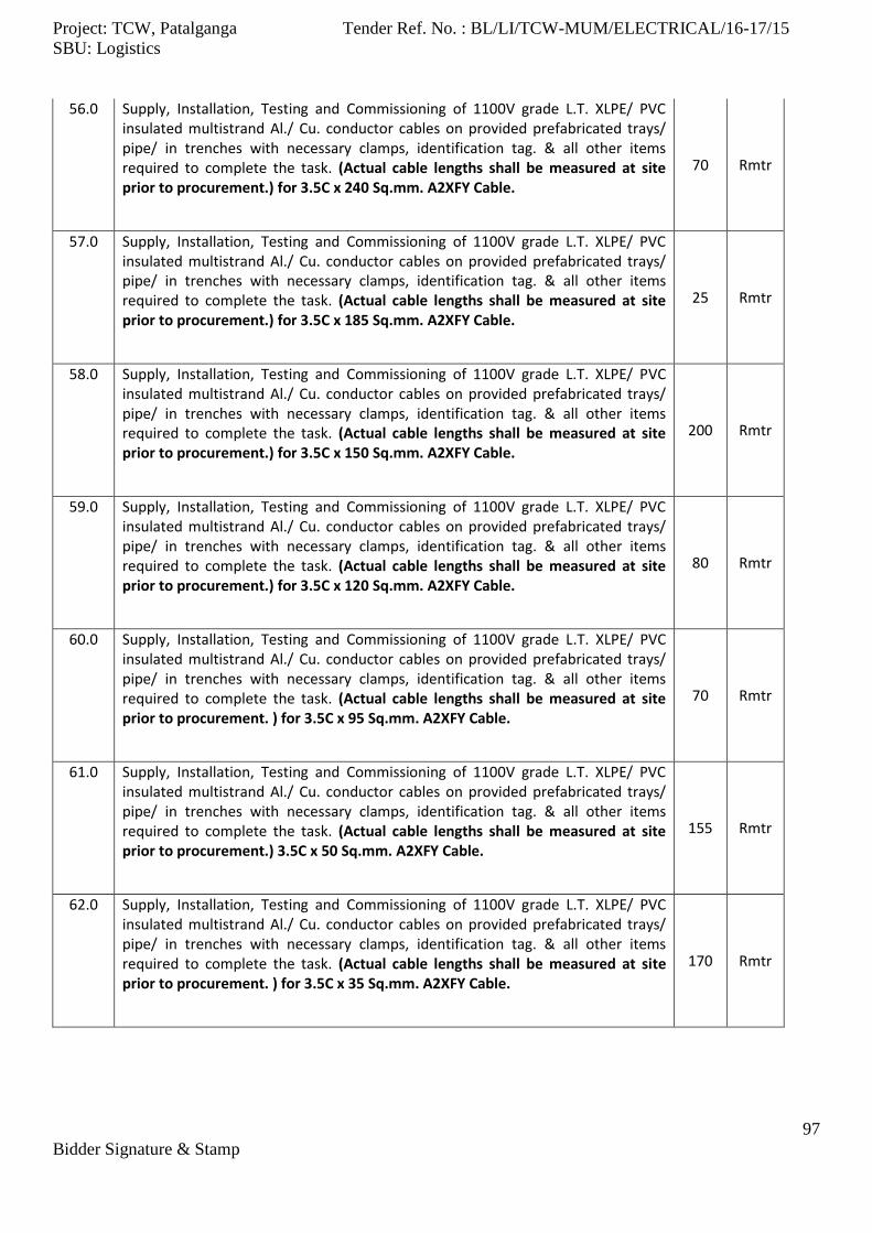
Project: TCW, Patalganga Tender Ref. No. : BL/LI/TCW-MUM/ELECTRICAL/16-17/15
SBU: Logistics
97
Bidder Signature & Stamp
56.0 Supply, Installation, Testing and Commissioning of 1100V grade L.T. XLPE/ PVC insulated multistrand Al./ Cu. conductor cables on provided prefabricated trays/ pipe/ in trenches with necessary clamps, identification tag. & all other items required to complete the task. (Actual cable lengths shall be measured at site prior to procurement.) for 3.5C x 240 Sq.mm. A2XFY Cable.
70 Rmtr
57.0 Supply, Installation, Testing and Commissioning of 1100V grade L.T. XLPE/ PVC insulated multistrand Al./ Cu. conductor cables on provided prefabricated trays/ pipe/ in trenches with necessary clamps, identification tag. & all other items required to complete the task. (Actual cable lengths shall be measured at site prior to procurement.) for 3.5C x 185 Sq.mm. A2XFY Cable.
25 Rmtr
58.0 Supply, Installation, Testing and Commissioning of 1100V grade L.T. XLPE/ PVC insulated multistrand Al./ Cu. conductor cables on provided prefabricated trays/ pipe/ in trenches with necessary clamps, identification tag. & all other items required to complete the task. (Actual cable lengths shall be measured at site prior to procurement.) for 3.5C x 150 Sq.mm. A2XFY Cable.
200 Rmtr
59.0 Supply, Installation, Testing and Commissioning of 1100V grade L.T. XLPE/ PVC insulated multistrand Al./ Cu. conductor cables on provided prefabricated trays/ pipe/ in trenches with necessary clamps, identification tag. & all other items required to complete the task. (Actual cable lengths shall be measured at site prior to procurement.) for 3.5C x 120 Sq.mm. A2XFY Cable.
80 Rmtr
60.0 Supply, Installation, Testing and Commissioning of 1100V grade L.T. XLPE/ PVC insulated multistrand Al./ Cu. conductor cables on provided prefabricated trays/ pipe/ in trenches with necessary clamps, identification tag. & all other items required to complete the task. (Actual cable lengths shall be measured at site prior to procurement. ) for 3.5C x 95 Sq.mm. A2XFY Cable.
70 Rmtr
61.0 Supply, Installation, Testing and Commissioning of 1100V grade L.T. XLPE/ PVC insulated multistrand Al./ Cu. conductor cables on provided prefabricated trays/ pipe/ in trenches with necessary clamps, identification tag. & all other items required to complete the task. (Actual cable lengths shall be measured at site prior to procurement.) 3.5C x 50 Sq.mm. A2XFY Cable.
155 Rmtr
62.0 Supply, Installation, Testing and Commissioning of 1100V grade L.T. XLPE/ PVC insulated multistrand Al./ Cu. conductor cables on provided prefabricated trays/ pipe/ in trenches with necessary clamps, identification tag. & all other items required to complete the task. (Actual cable lengths shall be measured at site prior to procurement. ) for 3.5C x 35 Sq.mm. A2XFY Cable.
170 Rmtr
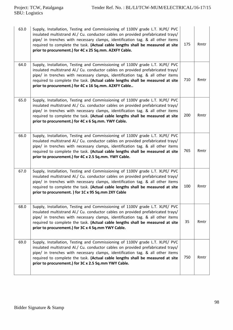
Project: TCW, Patalganga Tender Ref. No. : BL/LI/TCW-MUM/ELECTRICAL/16-17/15
SBU: Logistics
98
Bidder Signature & Stamp
63.0 Supply, Installation, Testing and Commissioning of 1100V grade L.T. XLPE/ PVC insulated multistrand Al./ Cu. conductor cables on provided prefabricated trays/ pipe/ in trenches with necessary clamps, identification tag. & all other items required to complete the task. (Actual cable lengths shall be measured at site prior to procurement.) for 4C x 25 Sq.mm. A2XFY Cable.
175 Rmtr
64.0 Supply, Installation, Testing and Commissioning of 1100V grade L.T. XLPE/ PVC insulated multistrand Al./ Cu. conductor cables on provided prefabricated trays/ pipe/ in trenches with necessary clamps, identification tag. & all other items required to complete the task. (Actual cable lengths shall be measured at site prior to procurement.) for 4C x 16 Sq.mm. A2XFY Cable..
710 Rmtr
65.0 Supply, Installation, Testing and Commissioning of 1100V grade L.T. XLPE/ PVC insulated multistrand Al./ Cu. conductor cables on provided prefabricated trays/ pipe/ in trenches with necessary clamps, identification tag. & all other items required to complete the task. (Actual cable lengths shall be measured at site prior to procurement.) for 4C x 6 Sq.mm. YWY Cable.
200 Rmtr
66.0 Supply, Installation, Testing and Commissioning of 1100V grade L.T. XLPE/ PVC insulated multistrand Al./ Cu. conductor cables on provided prefabricated trays/ pipe/ in trenches with necessary clamps, identification tag. & all other items required to complete the task. (Actual cable lengths shall be measured at site prior to procurement.) for 4C x 2.5 Sq.mm. YWY Cable.
765 Rmtr
67.0 Supply, Installation, Testing and Commissioning of 1100V grade L.T. XLPE/ PVC insulated multistrand Al./ Cu. conductor cables on provided prefabricated trays/ pipe/ in trenches with necessary clamps, identification tag. & all other items required to complete the task. (Actual cable lengths shall be measured at site prior to procurement. ) for 1C x 95 Sq.mm 2XY Cable
100 Rmtr
68.0 Supply, Installation, Testing and Commissioning of 1100V grade L.T. XLPE/ PVC insulated multistrand Al./ Cu. conductor cables on provided prefabricated trays/ pipe/ in trenches with necessary clamps, identification tag. & all other items required to complete the task. (Actual cable lengths shall be measured at site prior to procurement.) for 3C x 4 Sq.mm YWY Cable.
35 Rmtr
69.0 Supply, Installation, Testing and Commissioning of 1100V grade L.T. XLPE/ PVC insulated multistrand Al./ Cu. conductor cables on provided prefabricated trays/ pipe/ in trenches with necessary clamps, identification tag. & all other items required to complete the task. (Actual cable lengths shall be measured at site prior to procurement.) for 3C x 2.5 Sq.mm YWY Cable.
750 Rmtr
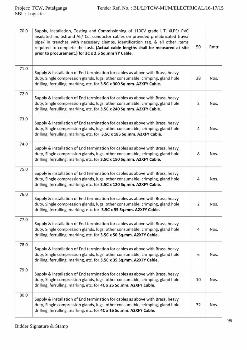
Project: TCW, Patalganga Tender Ref. No. : BL/LI/TCW-MUM/ELECTRICAL/16-17/15
SBU: Logistics
99
Bidder Signature & Stamp
70.0 Supply, Installation, Testing and Commissioning of 1100V grade L.T. XLPE/ PVC insulated multistrand Al./ Cu. conductor cables on provided prefabricated trays/ pipe/ in trenches with necessary clamps, identification tag. & all other items required to complete the task. (Actual cable lengths shall be measured at site prior to procurement.) for 3C x 2.5 Sq.mm YY Cable.
50 Rmtr
71.0 Supply & installation of End termination for cables as above with Brass, heavy duty, Single compression glands, lugs, other consumable, crimping, gland hole drilling, ferrulling, marking, etc. for 3.5C x 300 Sq.mm. A2XFY Cable.
28 Nos.
72.0 Supply & installation of End termination for cables as above with Brass, heavy duty, Single compression glands, lugs, other consumable, crimping, gland hole drilling, ferrulling, marking, etc. for 3.5C x 240 Sq.mm. A2XFY Cable.
2 Nos.
73.0 Supply & installation of End termination for cables as above with Brass, heavy duty, Single compression glands, lugs, other consumable, crimping, gland hole drilling, ferrulling, marking, etc. for 3.5C x 185 Sq.mm. A2XFY Cable.
4 Nos.
74.0 Supply & installation of End termination for cables as above with Brass, heavy duty, Single compression glands, lugs, other consumable, crimping, gland hole drilling, ferrulling, marking, etc. for 3.5C x 150 Sq.mm. A2XFY Cable.
8 Nos.
75.0 Supply & installation of End termination for cables as above with Brass, heavy duty, Single compression glands, lugs, other consumable, crimping, gland hole drilling, ferrulling, marking, etc. for 3.5C x 120 Sq.mm. A2XFY Cable.
4 Nos.
76.0 Supply & installation of End termination for cables as above with Brass, heavy duty, Single compression glands, lugs, other consumable, crimping, gland hole drilling, ferrulling, marking, etc. for 3.5C x 95 Sq.mm. A2XFY Cable.
2 Nos.
77.0 Supply & installation of End termination for cables as above with Brass, heavy duty, Single compression glands, lugs, other consumable, crimping, gland hole drilling, ferrulling, marking, etc. for 3.5C x 50 Sq.mm. A2XFY Cable.
4 Nos.
78.0 Supply & installation of End termination for cables as above with Brass, heavy duty, Single compression glands, lugs, other consumable, crimping, gland hole drilling, ferrulling, marking, etc. for 3.5C x 35 Sq.mm. A2XFY Cable.
6 Nos.
79.0 Supply & installation of End termination for cables as above with Brass, heavy duty, Single compression glands, lugs, other consumable, crimping, gland hole drilling, ferrulling, marking, etc. for 4C x 25 Sq.mm. A2XFY Cable.
10 Nos.
80.0 Supply & installation of End termination for cables as above with Brass, heavy duty, Single compression glands, lugs, other consumable, crimping, gland hole drilling, ferrulling, marking, etc. for 4C x 16 Sq.mm. A2XFY Cable.
32 Nos.
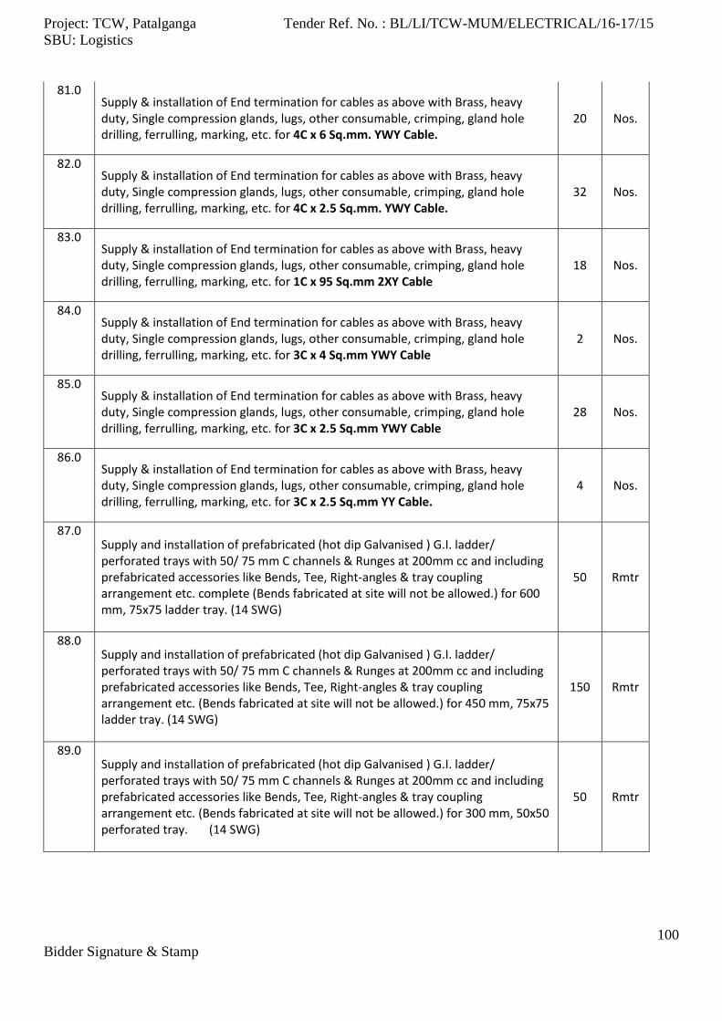
Project: TCW, Patalganga Tender Ref. No. : BL/LI/TCW-MUM/ELECTRICAL/16-17/15
SBU: Logistics
100
Bidder Signature & Stamp
81.0 Supply & installation of End termination for cables as above with Brass, heavy duty, Single compression glands, lugs, other consumable, crimping, gland hole drilling, ferrulling, marking, etc. for 4C x 6 Sq.mm. YWY Cable.
20 Nos.
82.0 Supply & installation of End termination for cables as above with Brass, heavy duty, Single compression glands, lugs, other consumable, crimping, gland hole drilling, ferrulling, marking, etc. for 4C x 2.5 Sq.mm. YWY Cable.
32 Nos.
83.0 Supply & installation of End termination for cables as above with Brass, heavy duty, Single compression glands, lugs, other consumable, crimping, gland hole drilling, ferrulling, marking, etc. for 1C x 95 Sq.mm 2XY Cable
18 Nos.
84.0 Supply & installation of End termination for cables as above with Brass, heavy duty, Single compression glands, lugs, other consumable, crimping, gland hole drilling, ferrulling, marking, etc. for 3C x 4 Sq.mm YWY Cable
2 Nos.
85.0 Supply & installation of End termination for cables as above with Brass, heavy duty, Single compression glands, lugs, other consumable, crimping, gland hole drilling, ferrulling, marking, etc. for 3C x 2.5 Sq.mm YWY Cable
28 Nos.
86.0 Supply & installation of End termination for cables as above with Brass, heavy duty, Single compression glands, lugs, other consumable, crimping, gland hole drilling, ferrulling, marking, etc. for 3C x 2.5 Sq.mm YY Cable.
4 Nos.
87.0 Supply and installation of prefabricated (hot dip Galvanised ) G.I. ladder/ perforated trays with 50/ 75 mm C channels & Runges at 200mm cc and including prefabricated accessories like Bends, Tee, Right-angles & tray coupling arrangement etc. complete (Bends fabricated at site will not be allowed.) for 600 mm, 75x75 ladder tray. (14 SWG)
50 Rmtr
88.0 Supply and installation of prefabricated (hot dip Galvanised ) G.I. ladder/ perforated trays with 50/ 75 mm C channels & Runges at 200mm cc and including prefabricated accessories like Bends, Tee, Right-angles & tray coupling arrangement etc. (Bends fabricated at site will not be allowed.) for 450 mm, 75x75 ladder tray. (14 SWG)
150 Rmtr
89.0 Supply and installation of prefabricated (hot dip Galvanised ) G.I. ladder/ perforated trays with 50/ 75 mm C channels & Runges at 200mm cc and including prefabricated accessories like Bends, Tee, Right-angles & tray coupling arrangement etc. (Bends fabricated at site will not be allowed.) for 300 mm, 50x50 perforated tray. (14 SWG)
50 Rmtr

Project: TCW, Patalganga Tender Ref. No. : BL/LI/TCW-MUM/ELECTRICAL/16-17/15
SBU: Logistics
101
Bidder Signature & Stamp
90.0 Supply and installation of prefabricated (hot dip Galvanised ) G.I. ladder/ perforated trays with 50/ 75 mm C channels & Runges at 200mm cc and including prefabricated accessories like Bends, Tee, Right-angles & tray coupling arrangement etc. (Bends fabricated at site will not be allowed.) for 200 mm, 50x50 perforated tray. (14 SWG)
100 Rmtr
91.0 Supply and installation of prefabricated (hot dip Galvanised ) G.I. ladder/ perforated trays with 50/ 75 mm C channels & Runges at 200mm cc and including prefabricated accessories like Bends, Tee, Right-angles & tray coupling arrangement etc. (Bends fabricated at site will not be allowed.) for 150 mm, 50x50 perforated tray. (16 SWG)
50 Rmtr
92.0 Supply and installation of prefabricated (hot dip Galvanised ) G.I. ladder/ perforated trays with 50/ 75 mm C channels & Runges at 200mm cc and including prefabricated accessories like Bends, Tee, Right-angles & tray coupling arrangement etc. (Bends fabricated at site will not be allowed.) for 50 mm, 50x50 perforated tray. (16 SWG)
650 Rmtr
93.0 Supply and installation of prefabricated (hot dip Galvanised ) G.I. tray covers (16 SWG) for following tray sizes including prefabricated accessories like Bends, Tee, Right-angles & tray coupling arrangement etc.(Bends fabricated at site will not be allowed.) for 300 mm, 50x50 perforated tray.
25 Rmtr
94.0 Supply and installation of prefabricated (hot dip Galvanised ) G.I. tray covers (16 SWG) for following tray sizes including prefabricated accessories like Bends, Tee, Right-angles & tray coupling arrangement etc.(Bends fabricated at site will not be allowed.) for 200 mm, 50x50 perforated tray.
25 Rmtr
95.0 Supply and installation of prefabricated (hot dip Galvanised ) G.I. tray covers (16 SWG) for following tray sizes including prefabricated accessories like Bends, Tee, Right-angles & tray coupling arrangement etc.(Bends fabricated at site will not be allowed.) for 150 mm, 50x50 perforated tray.
25 Rmtr
96.0 Supply and installation of prefabricated (hot dip Galvanised ) G.I. tray covers (16 SWG) for following tray sizes including prefabricated accessories like Bends, Tee, Right-angles & tray coupling arrangement etc.(Bends fabricated at site will not be allowed.) for 50 mm, 50x50 perforated tray.
350 Rmtr
97.0 Supply and fabrication of M.S. angle / channel supports for trays, frames, covers etc. including necessary painting with 2 coats of primer and 2 coats of enamel black paint. (Approval for Support arrangements to be taken from Client/Consultant prior to installation)
10 MT

Project: TCW, Patalganga Tender Ref. No. : BL/LI/TCW-MUM/ELECTRICAL/16-17/15
SBU: Logistics
102
Bidder Signature & Stamp
98.0 Supply and Installation of prefabricated G.I. strut supporting arrangement including cantilever supports from vertical support for above trays, frames, covers etc. including necessary powder coating with color approved by client (Approval for Support arrangements to be taken from Client / Consultant prior to installation)
600 Rmtr
99.0 Supply and fixing of Earthing pits as per IS 3043 using SIP/PIP electrode complete with watering pipe & suitable GI strip up to chamber, soil treatment with suitable backfill powder/compound, brick inspection chamber with 450x450 mm CI cover, disconnecting link complete including excavation or earth pit, refilling with Maintenance free Earth Electrode set comprising of 32 mm dia 3 mtrs long rod of Low carbon steel, molecular Copper Bonded for a thickness of 250 microns, highly conductive, ANSI NSF STD 60 Certified, with carbon based Backfill compound, according to BS 7430 & IEEE 80 and with suitable CU Clamp. Electrode specification: 32 mm dia, 3mtr length rod in 100 mm bore with conductive backfill compound. Make:-JEF ECOSAFE or equivalent.
46 Nos.
100.0 Supply, installation, testing of GI/ Cu. earthing strips & wires in ground at a depth of 600 mm. or in ready made trenches or on ready tray with necessary clamps & bimetallic srips as per specification for 75 x 6 mm. GI strip.
60 Rmtr
101.0 Supply, installation, testing of GI/ Cu. earthing strips & wires in ground at a depth of 600 mm. or in ready made trenches or on ready tray with necessary clamps & bimetallic srips as per specification for 50 x 10 mm. Cu strip.
55 Rmtr
102.0 Supply, installation, testing of GI/ Cu. earthing strips & wires in ground at a depth of 600 mm. or in ready made trenches or on ready tray with necessary clamps & bimetallic srips as per specification for 50 x 6 mm. Cu strip.
50 Rmtr
103.0 Supply, installation, testing of GI/ Cu. earthing strips & wires in ground at a depth of 600 mm. or in ready made trenches or on ready tray with necessary clamps & bimetallic srips as per specification for 50 x 6 mm. GI strip.
400 Rmtr
104.0 Supply, installation, testing of GI/ Cu. earthing strips & wires in ground at a depth of 600 mm. or in ready made trenches or on ready tray with necessary clamps & bimetallic srips as per specification for 32 x 6 mm. GI strip.
1100 Rmtr
105.0 Supply, installation, testing of GI/ Cu. earthing strips & wires in ground at a depth of 600 mm. or in ready made trenches or on ready tray with necessary clamps & bimetallic srips as per specification for 25 x 6 mm. GI strip.
160 Rmtr

Project: TCW, Patalganga Tender Ref. No. : BL/LI/TCW-MUM/ELECTRICAL/16-17/15
SBU: Logistics
103
Bidder Signature & Stamp
106.0 Supply, installation, testing of GI/ Cu. earthing strips & wires in ground at a depth of 600 mm. or in ready made trenches or on ready tray with necessary clamps & bimetallic srips as per specification for 25 x 3 mm. GI. strip.
100 Rmtr
107.0 Supply, installation, testing of GI/ Cu. earthing strips & wires in ground at a depth of 600 mm. or in ready made trenches or on ready tray with necessary clamps & bimetallic srips as per specification for 25 x 3 mm. Cu. strip
100 Rmtr
108.0 Supply, installation, testing of GI/ Cu. earthing strips & wires in ground at a depth of 600 mm. or in ready made trenches or on ready tray with necessary clamps & bimetallic srips as per specification for 32 x 6 mm. GI strip. Supported on Porcelain insulator/ J bolt at every 1.5 mtr interval for building L.A.
350 Rmtr
109.0 Supply and fixing of 8 SWG GI Wire. 1500 Rmtr
110.0 Supply and Fixing of 6.0 sqmm Cu. Cond. PVC insulated. 250 Rmtr
111.0 Supply and fixing of 4.0 sqmm Cu. Cond. PVC insulated. 250 Rmtr
112.0 Supply and fixing of Earthing Busbars with 50 x 6mm tinned cu strip, 500mm long on suitable insulators strip shall be provided with 8mm holes at every 75mm. 5 Set
113.0 Supply and fixing of Earthing Busbars with 50 x 6mm GI strip, 500mm long on suitable insulators strip shall be provided with 8mm holes at every 75mm. 5 Set
114.0 Supply, installation, testing & commissioning of Transducer type Building lightning arrester "EARLY STREAMER" to cover protection radius of 58.0 mtr. With 5 mtr height stem and fixing arrangement. (Indelec or Eqvt.). Required installation/ mounting details shall be submitted prior to installation.
1 Nos.
115.0 Supply, installation, testing of disconnecting link box for lightning down conductor at 1 mtr. from GL with SMC insulator and Gunmetal 50 x 6 mm disconnecting link. 2 Nos.
116.0 Supply, Installation, testing and commissioning of 30 kVA UPS consisting of Input 415V 3 Ph + N + E +/-10% 50Hz, Output 410V 3 Ph + N + E , -2% 50Hz, Unsymmetrical load with SMF battery backup for 15 min, Racks & Intercell connectors suitable for batteries and UPS to battery cabling.
1 Nos.
117.0 Supply and installation of mains for UPS power points in plant office area with 3 x 2.5 Sq.mm. Cu. YY cable including 25mm PVC Conduits upto switch board. 1200 Rmtr
118.0 Supply and Installation of 2 x 2.5 + 1 x 1.5 Cu wires in 25mm PVC conduit for loop in loop out of power points. 450 Rmtr
119.0 Providing & fixing 2 Nos. modular 5/15 A socket & switch with modular plate and box at one place for UPS & mains connections above table top. 5 Set
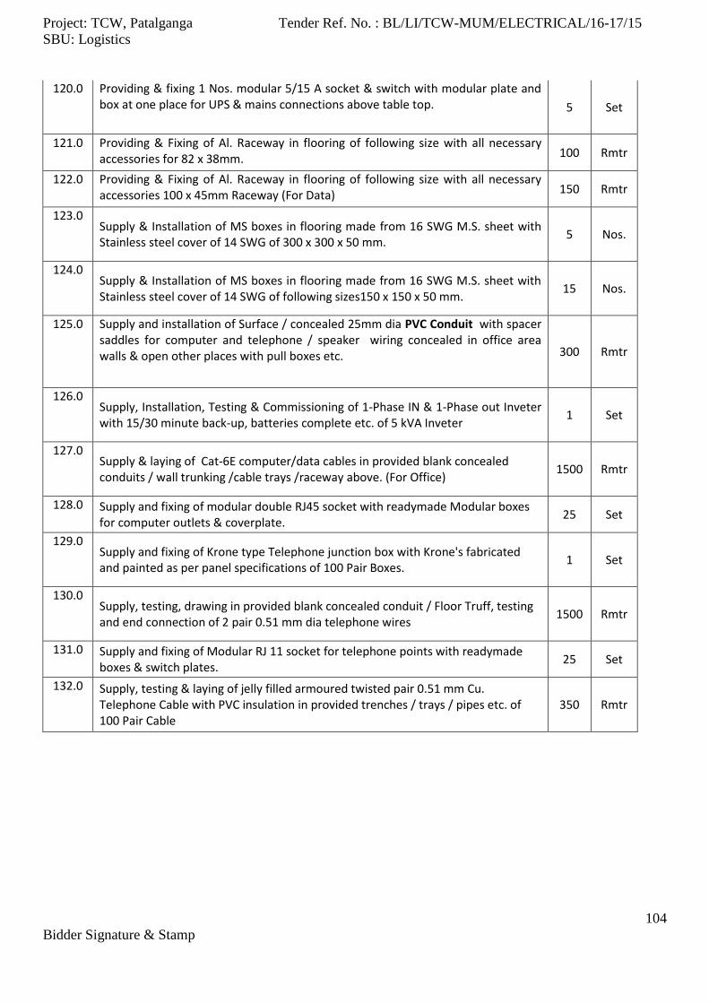
Project: TCW, Patalganga Tender Ref. No. : BL/LI/TCW-MUM/ELECTRICAL/16-17/15
SBU: Logistics
104
Bidder Signature & Stamp
120.0 Providing & fixing 1 Nos. modular 5/15 A socket & switch with modular plate and box at one place for UPS & mains connections above table top. 5 Set
121.0 Providing & Fixing of Al. Raceway in flooring of following size with all necessary accessories for 82 x 38mm. 100 Rmtr
122.0 Providing & Fixing of Al. Raceway in flooring of following size with all necessary accessories 100 x 45mm Raceway (For Data) 150 Rmtr
123.0 Supply & Installation of MS boxes in flooring made from 16 SWG M.S. sheet with Stainless steel cover of 14 SWG of 300 x 300 x 50 mm.
5 Nos.
124.0 Supply & Installation of MS boxes in flooring made from 16 SWG M.S. sheet with Stainless steel cover of 14 SWG of following sizes150 x 150 x 50 mm.
15 Nos.
125.0 Supply and installation of Surface / concealed 25mm dia PVC Conduit with spacer saddles for computer and telephone / speaker wiring concealed in office area walls & open other places with pull boxes etc. 300 Rmtr
126.0 Supply, Installation, Testing & Commissioning of 1-Phase IN & 1-Phase out Inveter with 15/30 minute back-up, batteries complete etc. of 5 kVA Inveter
1 Set
127.0 Supply & laying of Cat-6E computer/data cables in provided blank concealed conduits / wall trunking /cable trays /raceway above. (For Office)
1500 Rmtr
128.0 Supply and fixing of modular double RJ45 socket with readymade Modular boxes for computer outlets & coverplate.
25 Set
129.0 Supply and fixing of Krone type Telephone junction box with Krone's fabricated and painted as per panel specifications of 100 Pair Boxes.
1 Set
130.0 Supply, testing, drawing in provided blank concealed conduit / Floor Truff, testing and end connection of 2 pair 0.51 mm dia telephone wires
1500 Rmtr
131.0 Supply and fixing of Modular RJ 11 socket for telephone points with readymade boxes & switch plates.
25 Set
132.0 Supply, testing & laying of jelly filled armoured twisted pair 0.51 mm Cu. Telephone Cable with PVC insulation in provided trenches / trays / pipes etc. of 100 Pair Cable
350 Rmtr
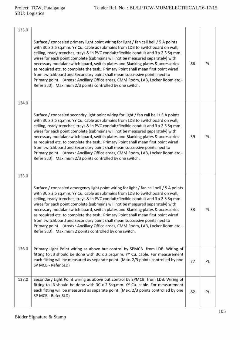
Project: TCW, Patalganga Tender Ref. No. : BL/LI/TCW-MUM/ELECTRICAL/16-17/15
SBU: Logistics
105
Bidder Signature & Stamp
133.0
Surface / concealed primary light point wiring for light / fan call bell / 5 A points with 3C x 2.5 sq.mm. YY Cu. cable as submains from LDB to Switchboard on wall, ceiling, ready trenches, trays & in PVC conduit/flexible conduit and 3 x 2.5 Sq.mm. wires for each point complete (submains will not be measured separately) with necessary modular switch board, switch plates and Blanking plates & accessories as required etc. to complete the task.. Primary Point shall mean first point wired from switchboard and Secondary point shall mean successive points next to Primary point. (Areas : Ancillary Office areas, CMM Room, LAB, Locker Room etc.-Refer SLD). Maximum 2/3 points controlled by one switch.
86 Pt.
134.0
Surface / concealed secondry light point wiring for light / fan call bell / 5 A points with 3C x 2.5 sq.mm. YY Cu. cable as submains from LDB to Switchboard on wall, ceiling, ready trenches, trays & in PVC conduit/flexible conduit and 3 x 2.5 Sq.mm. wires for each point complete (submains will not be measured separately) with necessary modular switch board, switch plates and Blanking plates & accessories as required etc. to complete the task.. Primary Point shall mean first point wired from switchboard and Secondary point shall mean successive points next to Primary point. (Areas : Ancillary Office areas, CMM Room, LAB, Locker Room etc.-Refer SLD). Maximum 2/3 points controlled by one switch.
39 Pt.
135.0
Surface / concealed emergency light point wiring for light / fan call bell / 5 A points with 3C x 2.5 sq.mm. YY Cu. cable as submains from LDB to Switchboard on wall, ceiling, ready trenches, trays & in PVC conduit/flexible conduit and 3 x 2.5 Sq.mm. wires for each point complete (submains will not be measured separately) with necessary modular switch board, switch plates and Blanking plates & accessories as required etc. to complete the task.. Primary Point shall mean first point wired from switchboard and Secondary point shall mean successive points next to Primary point. (Areas : Ancillary Office areas, CMM Room, LAB, Locker Room etc.-Refer SLD). Maximum 2 points controlled by one switch.
33 Pt.
136.0 Primary Light Point wiring as above but control by SPMCB from LDB. Wiring of fitting to JB should be done with 3C x 2.5sq.mm. YY Cu. cable. For measurement each fitting will be measured as separate point. (Max. 2/3 points controlled by one SP MCB - Refer SLD)
77 Pt.
137.0 Secondary Light Point wiring as above but control by SPMCB from LDB. Wiring of fitting to JB should be done with 3C x 2.5sq.mm. YY Cu. cable. For measurement each fitting will be measured as separate point. (Max. 2/3 points controlled by one SP MCB - Refer SLD)
82 Pt.
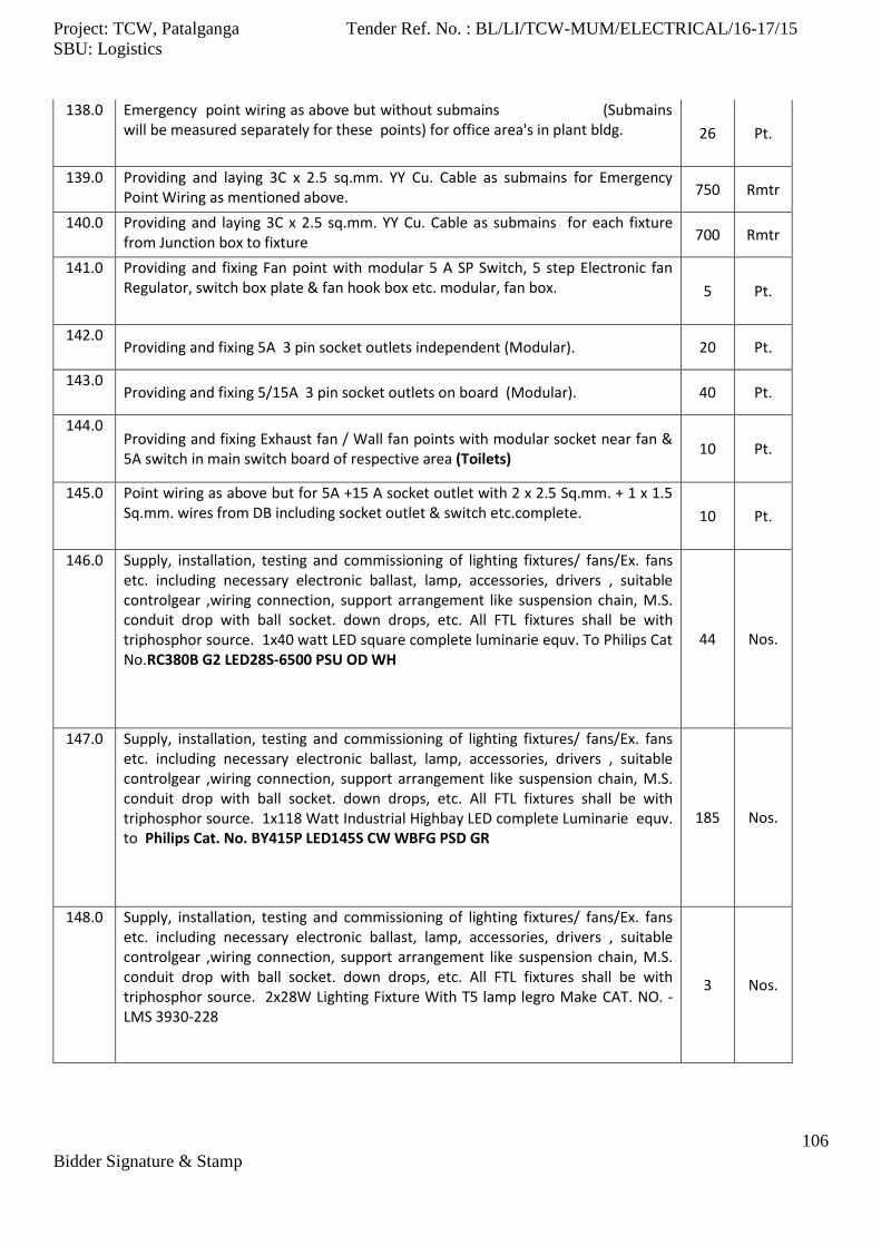
Project: TCW, Patalganga Tender Ref. No. : BL/LI/TCW-MUM/ELECTRICAL/16-17/15
SBU: Logistics
106
Bidder Signature & Stamp
138.0 Emergency point wiring as above but without submains (Submains will be measured separately for these points) for office area's in plant bldg. 26 Pt.
139.0 Providing and laying 3C x 2.5 sq.mm. YY Cu. Cable as submains for Emergency Point Wiring as mentioned above. 750 Rmtr
140.0 Providing and laying 3C x 2.5 sq.mm. YY Cu. Cable as submains for each fixture from Junction box to fixture 700 Rmtr
141.0 Providing and fixing Fan point with modular 5 A SP Switch, 5 step Electronic fan Regulator, switch box plate & fan hook box etc. modular, fan box. 5 Pt.
142.0 Providing and fixing 5A 3 pin socket outlets independent (Modular). 20 Pt.
143.0 Providing and fixing 5/15A 3 pin socket outlets on board (Modular). 40 Pt.
144.0 Providing and fixing Exhaust fan / Wall fan points with modular socket near fan & 5A switch in main switch board of respective area (Toilets)
10 Pt.
145.0 Point wiring as above but for 5A +15 A socket outlet with 2 x 2.5 Sq.mm. + 1 x 1.5 Sq.mm. wires from DB including socket outlet & switch etc.complete. 10 Pt.
146.0 Supply, installation, testing and commissioning of lighting fixtures/ fans/Ex. fans etc. including necessary electronic ballast, lamp, accessories, drivers , suitable controlgear ,wiring connection, support arrangement like suspension chain, M.S. conduit drop with ball socket. down drops, etc. All FTL fixtures shall be with triphosphor source. 1x40 watt LED square complete luminarie equv. To Philips Cat No.RC380B G2 LED28S-6500 PSU OD WH
44 Nos.
147.0 Supply, installation, testing and commissioning of lighting fixtures/ fans/Ex. fans etc. including necessary electronic ballast, lamp, accessories, drivers , suitable controlgear ,wiring connection, support arrangement like suspension chain, M.S. conduit drop with ball socket. down drops, etc. All FTL fixtures shall be with triphosphor source. 1x118 Watt Industrial Highbay LED complete Luminarie equv. to Philips Cat. No. BY415P LED145S CW WBFG PSD GR
185 Nos.
148.0 Supply, installation, testing and commissioning of lighting fixtures/ fans/Ex. fans etc. including necessary electronic ballast, lamp, accessories, drivers , suitable controlgear ,wiring connection, support arrangement like suspension chain, M.S. conduit drop with ball socket. down drops, etc. All FTL fixtures shall be with triphosphor source. 2x28W Lighting Fixture With T5 lamp legro Make CAT. NO. - LMS 3930-228
3 Nos.

Project: TCW, Patalganga Tender Ref. No. : BL/LI/TCW-MUM/ELECTRICAL/16-17/15
SBU: Logistics
107
Bidder Signature & Stamp
149.0 Supply, installation, testing and commissioning of lighting fixtures/ fans/Ex. fans etc. including necessary electronic ballast, lamp, accessories, drivers , suitable controlgear ,wiring connection, support arrangement like suspension chain, M.S. conduit drop with ball socket. down drops, etc. All FTL fixtures shall be with triphosphor source. 38Watt LED Industrial fitting complete luminarie equv. To Philips Cat No. BN 108C LED 40S PSU CDL WH
22 Nos.
150.0 Supply, installation, testing and commissioning of lighting fixtures/ fans/Ex. fans etc. including necessary electronic ballast, lamp, accessories, drivers , suitable controlgear ,wiring connection, support arrangement like suspension chain, M.S. conduit drop with ball socket. down drops, etc. All FTL fixtures shall be with triphosphor source. 42 Watt LED Industrial fitting (IP65) equv. to Philips Cat No. WT550 4' IP665 LED Batten (Wheather & water Proof)
12 Nos.
151.0 Supply, installation, testing and commissioning of lighting fixtures/ fans/Ex. fans etc. including necessary electronic ballast, lamp, accessories, drivers , suitable controlgear ,wiring connection, support arrangement like suspension chain, M.S. conduit drop with ball socket. down drops, etc. All FTL fixtures shall be with triphosphor source. 15W LED Downlight equv. to Philips Cat No. DN194B LED15S-6500 PSU WH S1
13 Nos.
152.0 Supply, installation, testing and commissioning of lighting fixtures/ fans/Ex. fans etc. including necessary electronic ballast, lamp, accessories, drivers , suitable controlgear ,wiring connection, support arrangement like suspension chain, M.S. conduit drop with ball socket. down drops, etc. All FTL fixtures shall be with triphosphor source. 24W LED Downlight equv. to Philips Cat No. (DN 395B LED20S-6500 PSR-P WH)
64 Nos.
153.0 Supply, Installation, Testing & Commissioning of Standalone Emergency Lights with battery backup upto 15min. & including 2' FTL lamp and necessary control circuit. 5 Nos.
154.0 Supply, installation testing of 150mm exhaust fans with mounting frame & louvers. 10 Nos.
155.0 Supply, Installation, Testing & Commissioning of Junction Boxes fabricated out of 14/16 SWG CRCA Sheet duly powder coated with approved color shade consisting of 15A, 4way connector strip and suitable for ease of cable termination of 150mm X 150mm X 65mm
350 Nos.

Project: TCW, Patalganga Tender Ref. No. : BL/LI/TCW-MUM/ELECTRICAL/16-17/15
SBU: Logistics
108
Bidder Signature & Stamp
156.0 Supply, Installation, testing and commissioning of L.T. panel boards Compartmental cubicle type, freestanding, IP65 with appropriate cable entries, & manufactured based on IS 8623, AEPPL specifications and single line diagrams. Scope shall include unloading, shifting, unpacking, Section assembly from storage place to desired Installation for Street Lighting DB (As per SLD)
1 Nos.
157.0 Supply, Installation, Testing and Commissioning of 1100V grade L.T. XLPE/ PVC insulated multistrand Al./ Cu. conductor cables on provided prefabricated trays/ pipe/ in trenches with necessary clamps, identification tag. & all other items required to complete the task for 4C X 6 AYFY
650
Rmtr
158.0 Supply, Installation, Testing and Commissioning of 1100V grade L.T. XLPE/ PVC insulated multistrand Al./ Cu. conductor cables on provided prefabricated trays/ pipe/ in trenches with necessary clamps, identification tag. & all other items required to complete the task for 3C X 2.5 YY (Terminal box to fitting)
250
Rmtr
159.0 Supply & installation of End termination for cables as above with Brass, heavy duty, Double compression glands, lugs, other consumable, crimping, gland hole drilling, ferrulling, marking, etc. for 4C X 16 AYFY 40
Nos.
160.0 Supply & installation of End termination for cables as above with Brass, heavy duty, Double compression glands, lugs, other consumable, crimping, gland hole drilling, ferrulling, marking, etc. for 3C X 2.5 YY (Terminal box to fitting) 40
Nos.
161.0 Supply, Installation of tubular/octogonal ,Galvanised , poles complete with 1400/1700/2000 x 550 x 550 mm foundation couping as per requirement, cable loop box with 15A 4 way connector, 10A SP MCB , spring type earthing of pole with 12 SWG wire.Pole for 7.5 Mtr.Galvanised Poles with single bracket for street light.
11 Nos.
162.0 Supply, Installation of tubular/octogonal ,Galvanised , poles complete with 1400/1700/2000 x 550 x 550 mm foundation couping as per requirement, cable loop box with 15A 4 way connector, 10A SP MCB , spring type earthing of pole with 12 SWG wire.Pole for 7.5 Mtr.Galvanised Poles with bracket for 2Nos. Of street light.
3 Nos.
163.0 Supply, Installation of tubular/octogonal ,Galvanised , poles complete with 1400/1700/2000 x 550 x 550 mm foundation couping as per requirement, cable loop box with 15A 4 way connector, 10A SP MCB , spring type earthing of pole with 12 SWG wire.Pole for 9.5 Mtr.Galvanised Poles with bracket for 1No. Of street light. & 1No. of flood light
4 Nos.
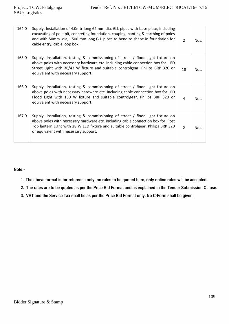
Project: TCW, Patalganga Tender Ref. No. : BL/LI/TCW-MUM/ELECTRICAL/16-17/15
SBU: Logistics
109
Bidder Signature & Stamp
164.0 Supply, Installation of 4.0mtr long 62 mm dia. G.I. pipes with base plate, including excavating of pole pit, concreting foundation, couping, panting & earthing of poles and with 50mm. dia, 1500 mm long G.I. pipes to bend to shape in foundation for cable entry, cable loop box.
2 Nos.
165.0 Supply, installation, testing & commissioning of street / flood light fixture on above poles with necessary hardware etc. including cable connection box for LED Street Light with 36/43 W fixture and suitable controlgear. Philips BRP 320 or equivalent with necessary support.
18 Nos.
166.0 Supply, installation, testing & commissioning of street / flood light fixture on above poles with necessary hardware etc. including cable connection box for LED Flood Light with 150 W fixture and suitable controlgear. Philips BRP 320 or equivalent with necessary support.
4 Nos.
167.0 Supply, installation, testing & commissioning of street / flood light fixture on above poles with necessary hardware etc. including cable connection box for Post Top lantern Light with 28 W LED fixture and suitable controlgear. Philips BRP 320 or equivalent with necessary support.
2 Nos.
Note:-
1. The above format is for reference only, no rates to be quoted here, only online rates will be accepted.
2. The rates are to be quoted as per the Price Bid Format and as explained in the Tender Submission Clause.
3. VAT and the Service Tax shall be as per the Price Bid Format only. No C-Form shall be given.

Project: TCW, Patalganga Tender Ref. No. : BL/LI/TCW-MUM/ELECTRICAL/16-17/15
SBU: Logistics
110
Bidder Signature & Stamp
ANNEXURE -III
Tender Drawings
Design, Supply, Fixing, Testing and Commissioning of H.T. & L.T. Electrical Works
Tender No. BL / LI/TCW -MUM/ ELECTRICAL /16-17 / 15
The following Drawings are attached for reference,
1. BLC223_TD_ELE_AB_00 – 1st Floor Lighting Layout 2. BLC223_TD_ELE_AB_00 – 1st Floor Power Layout 3. BLC223_TD_ELE_AB_00 – G.F. LT & Power Layout 4. BLC223_TD_ELE_AB_00 – SLD 5. BLC223_TD_ELE_MSLD_00 – Main SLD 6. BLC223_TD_ELE_MP_00 – Lighting Layout 7. BLC223_TD_ELE_MP_00 – Street Lighting Layout