project plan issue1.0d4 - research | university of...
TRANSCRIPT
SPIRESUBJECT: RAL Project Plan for SPIRE
PREPARED BY: K.J. King
DOCUMENT No: SPIRE-RAL-DOC-000346
ISSUE: 1.0 Draft 4 Date: 25th May 2001
CHECKED BY: …………………………………. Date: ………………………….
APPROVED BY: …………………………………. Date: ………………………….

Ref: SPIRE-RAL-DOC-000346
Issue: 1.0 Draft 4Date: 25 May 2001Page: 2 of 29
Project Document
SPIRE RAL Project Plan for SPIRE
Distribution
K.J. King Project ManagerB.M. Swinyard Instrument ScientistD.L. Smith AIV Facility ManagerJ. Payne EGSE ManagerT.G. Dimbylow ICC Development ManagerJ.A. Long Project Office Manager

Ref: SPIRE-RAL-DOC-000346
Issue: 1.0 Draft 4Date: 25 May 2001Page: 3 of 29
Project Document
SPIRE RAL Project Plan for SPIRE
CChhaannggee RReeccoorrdd
ISSUE DATE
Issue 1.0 Draft 1 9th August 2000 First draft of document for managers to reviewIssue 1.0 Draft 2 15th December 2000 Second DraftIssue 1.0 Draft 3 25th May 2001 Third Draft to be discussed for ISO9000 Audit
Ref: SPIRE-RAL-DOC-000346
Issue: 1.0 Draft 4Date: 25 May 2001Page: 4 of 29
Project Document
SPIRE RAL Project Plan for SPIRE
Table of Contents
1. Introduction .................................................................................................................................71.1 Scope .....................................................................................................................................71.2 Documents .............................................................................................................................7
1.2.1 Applicable Documents ......................................................................................................71.2.2 Reference Documents ......................................................................................................7
2. Project Breakdown ......................................................................................................................92.1 Work Allocation......................................................................................................................92.2 Identification of Models .........................................................................................................10
2.2.1 Avionics Model (AVM). .................................................................................................102.2.2 Cryogenic Qualification Model (CQM) (including Structural Thermal Model (STM))...........102.2.3 Proto-Flight Model..........................................................................................................112.2.4 Flight Spare Model..........................................................................................................11
2.3 Work Breakdown Structure ...................................................................................................112.4 Function Tree .......................................................................................................................122.5 Product Tree ........................................................................................................................142.6 Work Package Description ....................................................................................................16
3. Project Organisation...................................................................................................................163.1.1 General Organisation.......................................................................................................16
3.2 Management Interfaces.........................................................................................................173.3 Roles, Responsibilities and Authority.......................................................................................17
3.3.1 RAL Project Manager ....................................................................................................183.3.2 EGSE Manager ..............................................................................................................183.3.3 Project Office Manager ..................................................................................................183.3.4 AIV Facility Manager .....................................................................................................193.3.5 ICC Software Manager...................................................................................................19
3.4 Generation of Organisation Documents...................................................................................194. Project Phasing and Planning ......................................................................................................20
4.1 Instrument Hardware ............................................................................................................204.1.1 Sequence of Activities.....................................................................................................20
4.1.1.1 Design Phase .........................................................................................................204.1.1.2 Test and Qualification phase....................................................................................204.1.1.3 Flight Model Manufacture Phase .............................................................................20
4.1.2 Project Reviews .............................................................................................................214.2 ICC......................................................................................................................................21
5. Configuration Management.........................................................................................................215.1 Configuration Management tasks ...........................................................................................215.2 Implementation of Configuration Management ........................................................................215.3 Configuration Baseline...........................................................................................................215.4 Configuration Items ...............................................................................................................215.5 Change Control.....................................................................................................................21
6. Information/Documentation Management ....................................................................................227. Cost and Schedule Management .................................................................................................22
7.1 Cost Management.................................................................................................................22
Ref: SPIRE-RAL-DOC-000346
Issue: 1.0 Draft 4Date: 25 May 2001Page: 5 of 29
Project Document
SPIRE RAL Project Plan for SPIRE
7.2 Schedule Management ..........................................................................................................228. Technical Requirements .............................................................................................................229. Product Assurance Requirements ...............................................................................................2210. Systems Engineering.................................................................................................................22
List of Figures
Figure 3-1 RAL Project Organisation ..............................................................................................17Figure 4-1 SPIRE Overall Schedule ................................................................................................20
List of Tables
Table 2-1 SPIRE major tasks..........................................................................................................10Table 2-2 RAL Workpackages .......................................................................................................12Table 2-3 Functions to be executed at RAL.....................................................................................14Table 2-4 RAL Product Tree..........................................................................................................16
Ref: SPIRE-RAL-DOC-000346
Issue: 1.0 Draft 4Date: 25 May 2001Page: 6 of 29
Project Document
SPIRE RAL Project Plan for SPIRE
Glossary
CQM Cryogenic Qualification ModelESA European Space AgencyFIRST Far Infrared and Submillimetre TelescopeFS Flight Spare (Model)FTB FET BoxHCSS Herschel Common Science SystemHerschel Herschel Space Observatory (formerly FIRST)ICC Instrument Control CentrePFM Proto-Flight ModelPI Principle InvestigatorPIMS Project Information Management SystemPPARC Particle Physics and Astronomy Research CouncilRAL Rutherford Appleton LaboratoryRO Responsible OrganisationS/C SpacecraftSPIRE Spectral and Photometric Imaging REceiverSSTD Space Science and Technology Department (of RAL)STM Structural Thermal Model
Ref: SPIRE-RAL-DOC-000346
Issue: 1.0 Draft 4Date: 25 May 2001Page: 7 of 29
Project Document
SPIRE RAL Project Plan for SPIRE
1. INTRODUCTION
The Herschel Space Observatory, the fourth of ESA’s Cornerstone missions, is a space-borneobservatory operating in the far infrared and sub-millimetre wavelength ranges. The responsibility forthe design, implementation and operation of the scientific instruments on the Herschel spacecraft isgiven to consortia, made up from members of research institutions and universities, under the leadershipof a Principle Investigator (PI). The Rutherford Appleton Laboratory (RAL) is one of the institutesresponsible for providing and operating the Spectral and Photometric Imaging REceiver (SPIRE)instrument.
Current PPARC funding covers those activities leading to the delivery and commissioning of the Flightand Flight Spare instruments and to the implementation of the SPIRE Instrument Control Centre (ICC).It does not cover the Operations Phase or Post-Operations activities, which will be a subject of a furtherbid to PPARC at a later date.
1.1 ScopeThis document describes the management and development of those areas of the Herschel SPIREinstrument for which the RAL, and in particular the Space Science and Technology Department(SSTD), has responsibility. It is intended to show how the project will be managed to meet the ISO9000standard as implemented in the SSTD. It is the Project Management Plan identified in the SSTD TaskAllocation and Project Monitoring Procedure (AD01) and contains that information required by theProject Manager's Requirements Procedure (AD02).
As RAL is responsible for the overall management of the SPIRE project, many of the projectmanagement activities are covered by the appropriate SPIRE documentation. Where applicable thisdocument refers to material contained these existing SPIRE project documents, or contains extractsfrom them.
1.2 Documents
1.2.1 Applicable Documents
AD01 ISO9: SPAP/007 Task Allocation and Project MonitoringAD02 ISO9: SPAP/008 Project Manager's RequirementsAD03 SPIRE-RAL-PRJ-000029 SPIRE Management PlanAD04 SPIRE-ESA-DOC-000178 FIRST/Planck Instrument Interface Document (IID) Part
A, (SCI-PT-IIDA-04624)AD05 SPIRE-RAL-PRJ-000031 SPIRE Work Breakdown StructureAD06 SPIRE-RAL-PRJ-000030 SPIRE Product TreeAD07 SSTD Management Plan (Issue 7.1)AD08 SPIRE-ESA-DOC-000198 FIRST Science Implementation Requirements Document
1.2.2 Reference Documents
RD01 SPIRE-RAL-DOC-000184 SPIRE Project Office Requirements

Ref: SPIRE-RAL-DOC-000346
Issue: 1.0 Draft 4Date: 25 May 2001Page: 8 of 29
Project Document
SPIRE RAL Project Plan for SPIRE
RD02 SPIRE-RAL-PRJ-000455 SPIRE Major Milestone ListRD03 SPIRE-RAL-PRJ-000626 SPIRE Configuration Management PlanRD04 SPIRE-RAL-PRJ-000032 SPIRE Document Management PlanRD05 SPIRE-RAL-PRJ-000018 SPIRE Science Implementation PlanRD06 SPIRE-ESA-DOC-000189 Product Assurance Requirements for FIRST/PLANCK
Scientific InstrumentsRD07 SPIRE-RAL-PRJ-000017 SPIRE Product Assurance PlanRD08 SPIRE-RAL-PRJ-000033 SPIRE Configurable Documents TreeRD09 SPIRE-UCF-PRJ-000064 SPIRE Scientific Requirements DocumentRD10 SPIRE-RAL-PRJ-000034 SPIRE Instrument Requirements Document
Ref: SPIRE-RAL-DOC-000346
Issue: 1.0 Draft 4Date: 25 May 2001Page: 9 of 29
Project Document
SPIRE RAL Project Plan for SPIRE
2. PROJECT BREAKDOWN
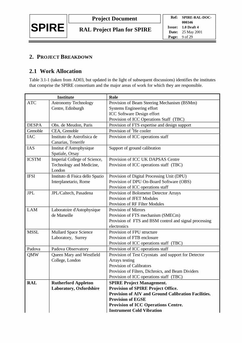
2.1 Work AllocationTable 3.1-1 (taken from AD03, but updated in the light of subsequent discussions) identifies the institutesthat comprise the SPIRE consortium and the major areas of work for which they are responsible.
Institute RoleATC Astronomy Technology
Centre, EdinburghProvision of Beam Steering Mechanism (BSMm)Systems Engineering effortICC Software Design effortProvision of ICC Operations Staff (TBC)
DESPA Obs. de Meudon, Paris Provision of FTS expertise and design supportGrenoble CEA, Grenoble Provision of 3He coolerIAC Instituto de Astrofisica de
Canarias, TenerifeProvision of ICC operations staff
IAS Institut d’AstrophysiqueSpatiale, Orsay
Support of ground calibration
ICSTM Imperial College of Science,Technology and Medicine,London
Provision of ICC UK DAPSAS CentreProvision of ICC operations staff (TBC)
IFSI Instituto di Fisica dello SpazioInterplanetario, Rome
Provision of Digital Processing Unit (DPU)Provision of DPU On-Board Software (OBS)Provision of ICC operations staff
JPL JPL/Caltech, Pasadena Provision of Bolometer Detector ArraysProvision of JFET ModulesProvision of RF Filter Modules
LAM Laboratoire d'Astophysiquede Marseille
Provision of MirrorsProvision of FTS mechanism (SMECm)Provision of FTS and BSM control and signal processingelectronics
MSSL Mullard Space ScienceLaboratory, Surrey
Provision of FPU structureProvision of FTB enclosureProvision of ICC operations staff (TBC)
Padova Padova Observatory Provision of ICC operations staffQMW Queen Mary and Westfield
College, LondonProvision of Test Cryostats and support for DetectorArrays testingProvision of CalibratorsProvision of Filters, Dichroics, and Beam DividersProvision of ICC operations staff (TBC)
RAL Rutherford AppletonLaboratory, Oxfordshire
SPIRE Project Management.Provision of SPIRE Project Office.Provision of AIV and Ground Calibration Facilities.Provision of EGSEProvision of ICC Operations Centre.Instrument Cold Vibration
Ref: SPIRE-RAL-DOC-000346
Issue: 1.0 Draft 4Date: 25 May 2001Page: 10 of 29
Project Document
SPIRE RAL Project Plan for SPIRE
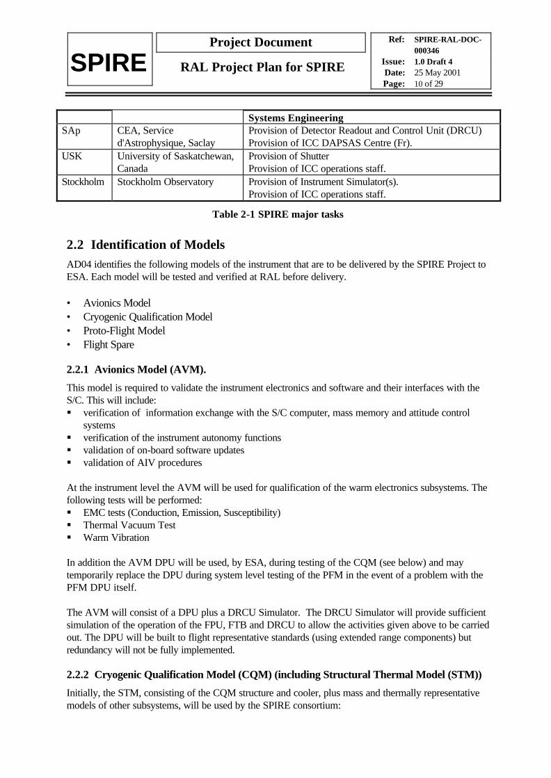
Systems EngineeringSAp CEA, Service
d'Astrophysique, SaclayProvision of Detector Readout and Control Unit (DRCU)Provision of ICC DAPSAS Centre (Fr).
USK University of Saskatchewan,Canada
Provision of ShutterProvision of ICC operations staff.
Stockholm Stockholm Observatory Provision of Instrument Simulator(s).Provision of ICC operations staff.
Table 2-1 SPIRE major tasks
2.2 Identification of ModelsAD04 identifies the following models of the instrument that are to be delivered by the SPIRE Project toESA. Each model will be tested and verified at RAL before delivery.
• Avionics Model• Cryogenic Qualification Model• Proto-Flight Model• Flight Spare
2.2.1 Avionics Model (AVM).
This model is required to validate the instrument electronics and software and their interfaces with theS/C. This will include:§ verification of information exchange with the S/C computer, mass memory and attitude control
systems§ verification of the instrument autonomy functions§ validation of on-board software updates§ validation of AIV procedures
At the instrument level the AVM will be used for qualification of the warm electronics subsystems. Thefollowing tests will be performed:§ EMC tests (Conduction, Emission, Susceptibility)§ Thermal Vacuum Test§ Warm Vibration
In addition the AVM DPU will be used, by ESA, during testing of the CQM (see below) and maytemporarily replace the DPU during system level testing of the PFM in the event of a problem with thePFM DPU itself.
The AVM will consist of a DPU plus a DRCU Simulator. The DRCU Simulator will provide sufficientsimulation of the operation of the FPU, FTB and DRCU to allow the activities given above to be carriedout. The DPU will be built to flight representative standards (using extended range components) butredundancy will not be fully implemented.
2.2.2 Cryogenic Qualification Model (CQM) (including Structural Thermal Model (STM))
Initially, the STM, consisting of the CQM structure and cooler, plus mass and thermally representativemodels of other subsystems, will be used by the SPIRE consortium:
Ref: SPIRE-RAL-DOC-000346
Issue: 1.0 Draft 4Date: 25 May 2001Page: 11 of 29
Project Document
SPIRE RAL Project Plan for SPIRE
• To qualify the cold instrument structure design against the proposed environmental test levels and toderive the test levels for other subsystems.
• To verify the thermal design of the instrument• To verify the optical alignment procedure for the instrument
Subsequently the CQM models of all subsystems will be integrated into the structure and the CQMinstrument will be subjected to a series of functional and scientific performance tests. On delivery toESA it will be used to ensure the compatibility of the Herschel payload and spacecraft by performing aseries of functional tests and a set of conductive EMC tests in the ISO Flight Spare Cryostat.
The CQM units will be built to flight standards with full redundancy. The performance capabilities of theinstrument may be less than the PFM - i.e. fewer pixels in the focal plane arrays, but it will mimic asexactly as possible the thermal, electrical and mechanical properties of the flight instrument and will becapable of under going the full environmental qualification programme.
This model consists of the FPU, FTB and DRCU only. It is assumed that the AVM DPU may be usedfor the duration of the CQM tests.
2.2.3 Proto-Flight Model
This is the instrument model that is intended for flight. It consists of all SPIRE Instrument Units. It willbe built to full flight standards and will only have minor differences in thermal, electrical and mechanicalproperties to the CQM. It will have the same mechanical, thermal and electrical interfaces to thesatellite as the CQM but, may, however, have minor internal design changes compared to the CQM.For instance the bolometer detector arrays may have many more pixels.
The PFM will undergo environmental test to qualification levels for acceptance times (TBD) - thisapplies to both the warm electronics boxes and the cold FPU.
2.2.4 Flight Spare Model
The Flight Spare Model provides for replacement of failed, or damaged, units during system leveltesting.
The FS will consist of a full flight standard, calibrated (TBC), FPU and FTB, and tested spare parts(normally at board level) for the DPU and DRCU.
It is possible that the Flight Spare Units may be provided from refurbished AVM and CQM units.
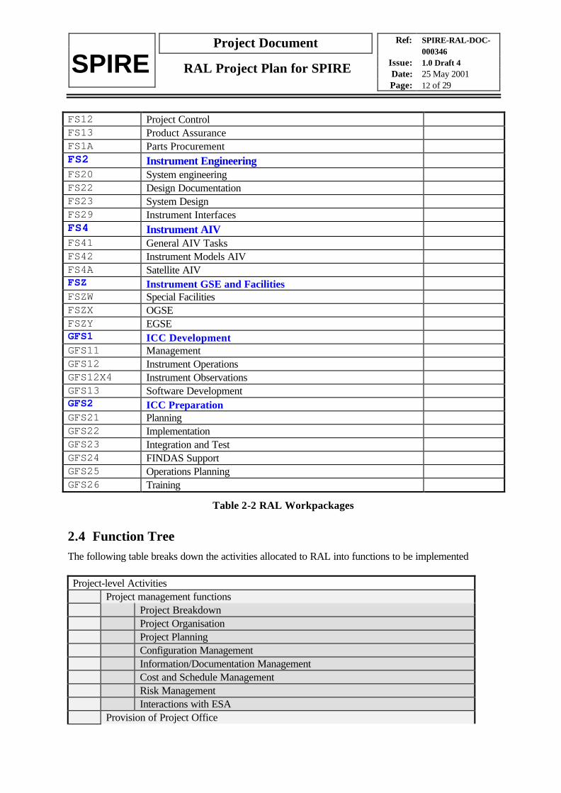
2.3 Work Breakdown StructureThe SPIRE Work Breakdown Structure is provided in AD05. Table 2-2 lists the high-levelworkpackages assigned to RAL:
FS1 Project-level ActivitiesFS10 Project OfficeFS11 Management
Ref: SPIRE-RAL-DOC-000346
Issue: 1.0 Draft 4Date: 25 May 2001Page: 12 of 29
Project Document
SPIRE RAL Project Plan for SPIRE
FS12 Project ControlFS13 Product AssuranceFS1A Parts ProcurementFS2 Instrument EngineeringFS20 System engineeringFS22 Design DocumentationFS23 System DesignFS29 Instrument InterfacesFS4 Instrument AIVFS41 General AIV TasksFS42 Instrument Models AIVFS4A Satellite AIVFSZ Instrument GSE and FacilitiesFSZW Special FacilitiesFSZX OGSEFSZY EGSEGFS1 ICC DevelopmentGFS11 ManagementGFS12 Instrument OperationsGFS12X4 Instrument ObservationsGFS13 Software DevelopmentGFS2 ICC PreparationGFS21 PlanningGFS22 ImplementationGFS23 Integration and TestGFS24 FINDAS SupportGFS25 Operations PlanningGFS26 Training
Table 2-2 RAL Workpackages
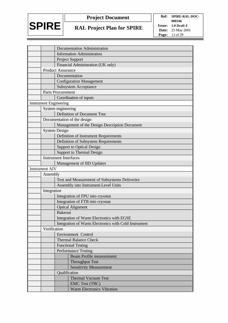
2.4 Function TreeThe following table breaks down the activities allocated to RAL into functions to be implemented
Project-level ActivitiesProject management functions
Project BreakdownProject OrganisationProject PlanningConfiguration ManagementInformation/Documentation ManagementCost and Schedule ManagementRisk ManagementInteractions with ESA
Provision of Project Office
Ref: SPIRE-RAL-DOC-000346
Issue: 1.0 Draft 4Date: 25 May 2001Page: 13 of 29
Project Document
SPIRE RAL Project Plan for SPIRE
Documentation AdministrationInformation AdministrationProject SupportFinancial Administration (UK only)
Product AssuranceDocumentationConfiguration ManagementSubsystem Acceptance
Parts ProcurementCoordination of inputs
Instrument EngineeringSystem engineering
Definition of Document TreeDocumentation of the design
Management of the Design Description DocumentSystem Design
Definition of Instrument RequirementsDefinition of Subsystem RequirementsSupport to Optical DesignSupport to Thermal Design
Instrument InterfacesManagement of IID Updates
Instrument AIVAssembly
Test and Measurement of Subsystems DeliveriesAssembly into Instrument-Level Units
IntegrationIntegration of FPU into cryostatIntegration of FTB into cryostatOptical AlignmentBakeoutIntegration of Warm Electronics with EGSEIntegration of Warm Electronics with Cold Instrument
VerificationEnvironment ControlThermal Balance CheckFunctional TestingPerformance Testing
Beam Profile measurementThroughput TestSensitivity Measurement
QualificationThermal Vacuum TestEMC Test (TBC)Warm Electronics Vibration

Ref: SPIRE-RAL-DOC-000346
Issue: 1.0 Draft 4Date: 25 May 2001Page: 14 of 29
Project Document
SPIRE RAL Project Plan for SPIRE
Cold Instrument VibrationCalibration
Photometric CalibrationClosed Cryostat TestsExternal Source Tests
Spectroscopic CalibrationWavelength Calibration
Instrument GSE and FacilitiesProvision of Test FacilityCommissioning of Test FacilityOperation of Test FacilityProvision of EGSE
ICC DevelopmentICC Development ManagementData Processing Software DevelopmentICC System TestingGround Segment TestingInstrument Simulator
ICC PreparationInstrument DatabaseOperations PlanningTraining
Table 2-3 Functions to be executed at RAL
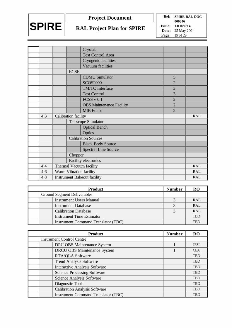
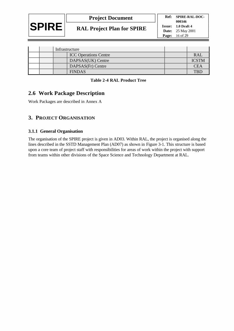
2.5 Product TreeTable 2-4 is a summary of the relevant major elements of the SPIRE Product tree identified in theSPIRE Product Tree (AD06) which have to be provided by RAL.
Product Number RO4. AIV/Ground Test Items
4.1 EMC test facility RAL
Radiative emission test facilityRadiative susceptibility test facilityConductive emission test facilityConductive susceptibility test facility
4.2 AIV facilities RAL
Integration FacilityClean RoomClean BenchMeasurement Instrumentation
Instrument CryostatFacility electronicsClean RoomInfrastructure 1
Ref: SPIRE-RAL-DOC-000346
Issue: 1.0 Draft 4Date: 25 May 2001Page: 15 of 29
Project Document
SPIRE RAL Project Plan for SPIRE
CryolabTest Control AreaCryogenic facilitiesVacuum facilities
EGSECDMU Simulator 5SCOS2000 2TM/TC Interface 3Test Control 3FCSS v 0.1 2OBS Maintenance Facility 2MIB Editor 2
4.3 Calibration facility RAL
Telescope SimulatorOptical BenchOptics
Calibration SourcesBlack Body SourceSpectral Line Source
ChopperFacility electronics
4.4 Thermal Vacuum facility RAL
4.6 Warm Vibration facility RAL
4.8 Instrument Bakeout facility RAL
Product Number ROGround Segment Deliverables
Instrument Users Manual 3 RAL
Instrument Database 3 RAL
Calibration Database 3 RALInstrument Time Estimator TBD
Instrument Command Translator (TBC) TBD
Product Number ROInstrument Control Centre
DPU OBS Maintenance System 1 IFSI
DRCU OBS Maintenance System 1 CEA
RTA/QLA Software TBD
Trend Analysis Software TBD
Interactive Analysis Software TBD
Science Processing Software TBD
Science Analysis Software TBD
Diagnostic Tools TBD
Calibration Analysis Software TBD
Instrument Command Translator (TBC) TBD
Ref: SPIRE-RAL-DOC-000346
Issue: 1.0 Draft 4Date: 25 May 2001Page: 16 of 29
Project Document
SPIRE RAL Project Plan for SPIRE
InfrastructureICC Operations Centre RALDAPSAS(UK) Centre ICSTMDAPSAS(Fr) Centre CEAFINDAS TBD
Table 2-4 RAL Product Tree
2.6 Work Package DescriptionWork Packages are described in Annex A
3. PROJECT ORGANISATION
3.1.1 General Organisation
The organisation of the SPIRE project is given in AD03. Within RAL, the project is organised along thelines described in the SSTD Management Plan (AD07) as shown in Figure 3-1. This structure is basedupon a core team of project staff with responsibilities for areas of work within the project with supportfrom teams within other divisions of the Space Science and Technology Department at RAL.

Ref: SPIRE-RAL-DOC-000346
Issue: 1.0 Draft 4Date: 25 May 2001Page: 17 of 29
Project Document
SPIRE RAL Project Plan for SPIRE
Project ManagerK.J. King
InstrumentScientist
B.M. Swinyard
Project OfficeManager
Mrs J.A. Long
OperationsScientist
S.D. Sidher
Project DirectorR.J. Emery
PA ManagerE.A. Clark
Test ScientistTBD
AssistantSys. EngD. Griffin
SPIREProject
Positions
RALSPIRE Project
Positions
ICC DevelopmentManagerK.J. King
SystemsEngineer
J. Delderfield
System EngineerS.Sidher
M. GrahamM. Fox
ICSTM
TBD
Padua
SoftwareManagerS. Guest
Optics Group
M. Sauvage
CEA
Thermal Group
Test FacilityManager
D.L. Smith
C. Morriset
Meudon
TBD ATC
EGSEManagerJ. Payne
S. Guest
SpaceInstrumentation
Electronics Group
S.Sidher
H. Morris
Mechanical Designand Facilities
Group
SpaceInstrumentation
Electronics Group
Optics Group
RALTechnologyDepartment
InstrumentDevelopment
ManagerE.C. Sawyer
ExternalGroups
Figure 3-1 RAL Project Organisation
3.2 Management InterfacesAD03 describes the project interfaces with ESA and with the other members of the SPIRE consortium.
Within RAL, the interfaces to teams within other divisions shall be described in Statements of Work,agreed between the relevant SPIRE manager and the manager of the SSTD facility.
SPIRE Managers report to the Project Manager at regular Project Management Meetings and throughmonthly reports.
3.3 Roles, Responsibilities and AuthoritySome members of the RAL team (Project Manager, Instrument Development Manager, InstrumentScientist, Systems Engineer, Product Assurance Manager, Operations Scientist and ICC DevelopmentManager) have roles and responsibilities within the SPIRE Project as a whole. These are described inthe SPIRE Management Plan (AD03).
Ref: SPIRE-RAL-DOC-000346
Issue: 1.0 Draft 4Date: 25 May 2001Page: 18 of 29
Project Document
SPIRE RAL Project Plan for SPIRE
Others (Project Director and RAL Project Manager) have roles and responsibilities within the SSTDproject management structure, which are described in the SSTD Management Plan (AD07).
The remainder of this section lists each of the other key posts and gives the duties and responsibilitiesassociated with that post within RAL.
3.3.1 RAL Project Manager
The management of the activities falling under the responsibility of RAL shall be under the control of theRAL Project Manager, who will:
(i) define the overall schedule necessary to meet the project milestones;(ii) monitor the project-wide deployment of resources;(iii) proactively manage technical and schedule risks;(iv) monitor progress in the development teams;(v) instigate project reviews, studies and assessments as necessary to resolve issues and ensure a
successful project;(vi) represent the SPIRE project to the SPIRE Project management team.(vii) represent the RAL project to the PPARC SPIRE Programme Manager and the Herschel/Planck
Steering Committee(viii) represent the RAL Project to the SSTD Management.
3.3.2 EGSE Manager
The EGSE Manager is responsible for the procurement and development of the EGSE system(s) usedfor testing the instrument models at RAL and at ESA. He/she will:
1. define the requirements on the EGSE, taking into account the need to adhere to agreements withother instruments, and ESA, with respect to common development.
2. define the tasks necessary, and the required resources, to provide the EGSE.3. identify appropriate staff/facilities for the tasks involved and negotiate their availability.4. plan the development and implementation schedule to meet the overall project delivery dates.5. monitor and manage the work, and staff, during the project lifetime.6. report to the RAL Project Manager on the status of the EGSE development programme.
Note: Operation of the EGSE during AIV falls under the responsibility of the AIV Facility Manager.
3.3.3 Project Office Manager
The Project Office Manager is responsible for the implementation of the facilities required in the SPIREProject Office (defined in the SPIRE Project Office Requirements Document, RD01) and the operationof the Project Office during the lifetime of the project. He/she will:
1. implement the SPIRE Project Office at RAL to meet the requirements2. document the procedures required to operate the Project Office efficiently and correctly3. operate the SPIRE Project Office at RAL4. report to the RAL Project Manager on the status of the Project Office
Ref: SPIRE-RAL-DOC-000346
Issue: 1.0 Draft 4Date: 25 May 2001Page: 19 of 29
Project Document
SPIRE RAL Project Plan for SPIRE
Note: The Project Office has an extended role over the normal RAL model and therefore, though it usesthe SSTD facilities , exists independently of the SSTD project Resources section.
3.3.4 AIV Facility Manager
1. define the requirements on the SPIRE Test Facility at RAL2. implement the SPIRE Test Facility at RAL to meet the requirements and schedule3. report to the RAL Project Manager on the status of the Test Facility4. manage the execution of the AIV Plan at RAL5. report to the RAL Project manager and the Instrument Scientist on the progress of the AIV
activities
3.3.5 ICC Software Manager
The ICC software Manager is responsible for organising the design and implementation of the ICCsoftware used both in the iCC and in the HCSS. He will:
1. define the ICC software requirements in terms of Use cases and translate these into an object -oriented design for the software
2. support the ICC Development Manager in producing the SPIRE SIP by producing workpackagesfor the software development activities
3. lead the ICC Software Development Team in implementing the ICC software.
3.4 Generation of Organisation DocumentsThe project documentation tree is given in RD08.

Ref: SPIRE-RAL-DOC-000346
Issue: 1.0 Draft 4Date: 25 May 2001Page: 20 of 29
Project Document
SPIRE RAL Project Plan for SPIRE
4. PROJECT PHASING AND PLANNING
4.1 Instrument Hardware
4.1.1 Sequence of Activities
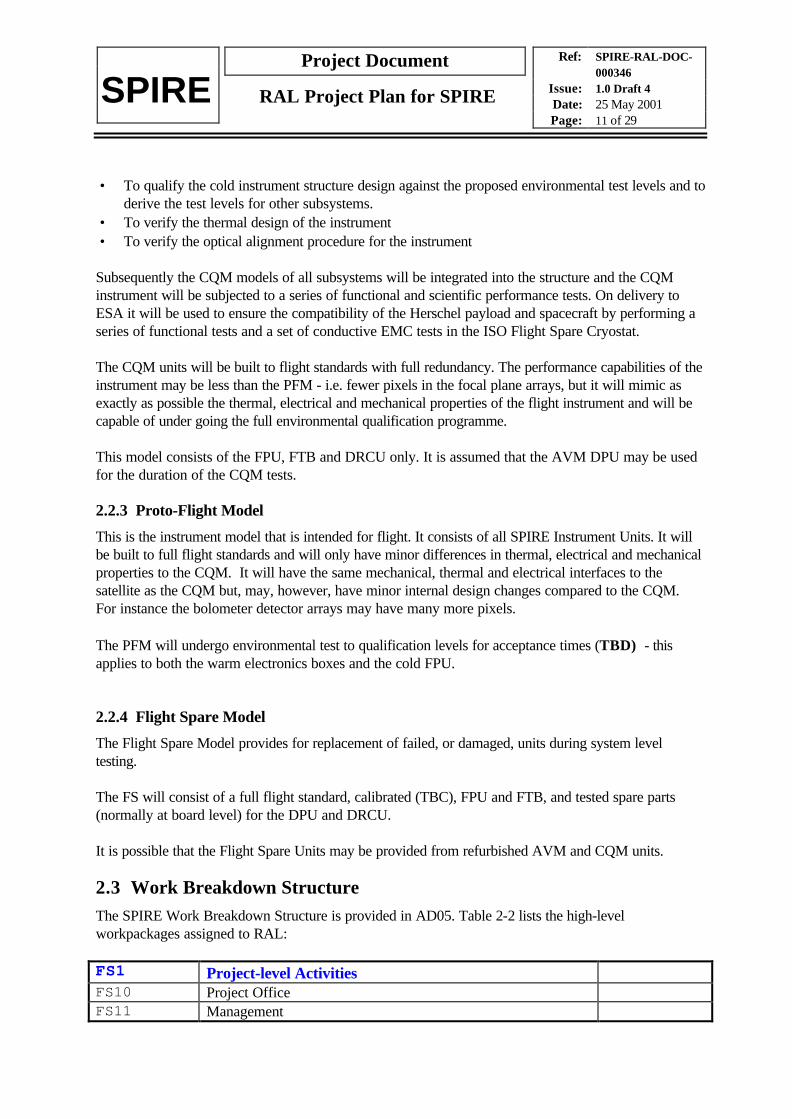
Figure 4-1 shows the SPIRE overall hardware schedule. It is split into 4 phases:
4.1.1.1 Design Phase
During this phase the instrument and subsystem designs are completed. This phase ends with thecompletion of the Instrument Baseline Design Review.
4.1.1.2 Test and Qualification phase
During this phase the first models of the instrument are manufactured and tested. This phase ends withthe Critical Design Review.
4.1.1.3 Flight Model Manufacture Phase
This phase covers the manufacture, test and calibration of the Flight and Flight Spare models of theinstrument
Q1
1999Q2 Q3 Q4 Q1
2000Q2 Q3 Q4 Q1
2001Q2 Q3 Q4 Q1
2002Q2 Q3 Q4 Q1
2006Q2 Q3 Q4Q1
2005Q2 Q3 Q4Q1
2004Q2 Q3 Q4Q1
2003Q2 Q3 Q4 Q1
2007Q2 Q3 Q4
PFM Manfr.
PFM AIV/Cal
Critical Design Review
STM AIV
Interface Review
STM/CQM Manufacture
Array Selection
PDR
Preliminary Design
Detailed Design
AVM Manufacture
AVM Int.
FS Delivery
FS Build/Refurbish
FS AIV
Launch
AVM Delivery
CQM Delivery
PFM Delivery
AVM Verif.
EQM
CQM AIV
System Tests
Figure 4-1 SPIRE Overall Schedule
Ref: SPIRE-RAL-DOC-000346
Issue: 1.0 Draft 4Date: 25 May 2001Page: 21 of 29
Project Document
SPIRE RAL Project Plan for SPIRE
A list of the principal project milestones is given in RD02.
4.1.2 Project Reviews
The project review plan is described in AD03. The dates of the reviews are listed in RD02
4.2 ICCThe planning for the ICC is described in the Science Implementation Plan (RD05).
5. CONFIGURATION MANAGEMENT
5.1 Configuration Management tasksThe plan for configuration management and control is given in RD03.
5.2 Implementation of Configuration ManagementThe Project will use the SSTD Project Information Management System (PIMS) for configurationcontrol. This system will be set up and operated by the PA Manager.
The project documentation is held on an external site (Livelink at ESA) and so cannot be held in PIMS.Procedures for change control of the project documents are given in RD04.
The classes of document that are required to be under configuration control are defined in RD04.
5.3 Configuration BaselineSee RD03
5.4 Configuration ItemsSee RD03
5.5 Change ControlSee RD03
Ref: SPIRE-RAL-DOC-000346
Issue: 1.0 Draft 4Date: 25 May 2001Page: 22 of 29
Project Document
SPIRE RAL Project Plan for SPIRE
6. INFORMATION/DOCUMENTATION MANAGEMENT
Documentation management is described in RD04
7. COST AND SCHEDULE MANAGEMENT
7.1 Cost ManagementThe Project Office maintains a spreadsheet of all project income and spend. At the end of each monththis is compared with the FRS output and any discrepancies are resolved with the RAL Admin group.
Reports on project spend are made quarterly to PPARC and the Herschel/Planck Project Director.
7.2 Schedule ManagementRD02 contains the project milestones relating to deliveries between SPIRE institutes and betweenSPIRE and ESA. This document will be maintained under configuration control and changes will besubject to approval.
Institutes shall provide schedules meeting these milestones and report on their status at the weeklyproject managers teleconference. Any changes in schedule will need approval from the project beforebeing incorporated into the milestone list.
8. TECHNICAL REQUIREMENTS
Requirements on the instrument are generated from the SPIRE scientific requirements (RD09) in theform of a set of instrument requirements (RD10). The interface to the spacecraft is documented inAD04
The ICC requirements are given in AD08
9. PRODUCT ASSURANCE REQUIREMENTS
The requirements put on the SPIRE project are defined in RD06. The SPIRE response to these isspecified in the SPIRE PA Plan (RD07).
10. SYSTEMS ENGINEERING
TBW

Ref: SPIRE-RAL-DOC-000346
Issue: 1.0 Draft 4Date: 25 May 2001Page: 23 of 29
Project Document
SPIRE RAL Project Plan for SPIRE
ANNEX 1Workpackages
FS1 Project-level ActivitiesFS10 Project OfficeFS100X1000 Provision of SPIRE Project Office RALFS101X1000 Operation of SPIRE Project Office RALFS11 ManagementFS110X1000 Support to ESA RALFS111X1000 Organisation of Reviews RALFS12 Project ControlFS120X1000 Project Planning RALFS121X1000 Project Control RALFS13 Product AssuranceFS130X1000 Product Assurance RALFS131X1000 Quality Assurance RALFS1A Parts ProcurementFS1A0X1000 Parts Procurement Co-ordination RALFS1A1X1000 Parts Procurement for UK groups RAL
FS2 Instrument EngineeringFS20 System engineeringFS200X1000 System Engineering RALFS22 Design DocumentationFS220X1000 Instrument Requirements Document RALFS23 System DesignFS230X1000 Instrument Requirements RALFS231X1000 Instrument Interfaces RALFS29 Instrument InterfacesFS290X1000 Instrument Interface Document, Part B RAL
FS4 Instrument AIVFS41 General AIV TasksFS410X1000 Engineering Test Preparation RALFS411X1000 Calibration Preparation RAL+FS412X1000 AIV Team Training RALFS42 Instrument Models AIVFS420A1000 AVM Integration RAL+FS420A2000 AVM Verification RAL+FS420C1000 STM Assembly RAL+FS420C2000 STM Integration RAL+FS420C3000 STM Verification RAL+FS420C4000 CQM Assembly RAL+FS420C5000 CQM Integration RAL+
Ref: SPIRE-RAL-DOC-000346
Issue: 1.0 Draft 4Date: 25 May 2001Page: 24 of 29
Project Document
SPIRE RAL Project Plan for SPIRE
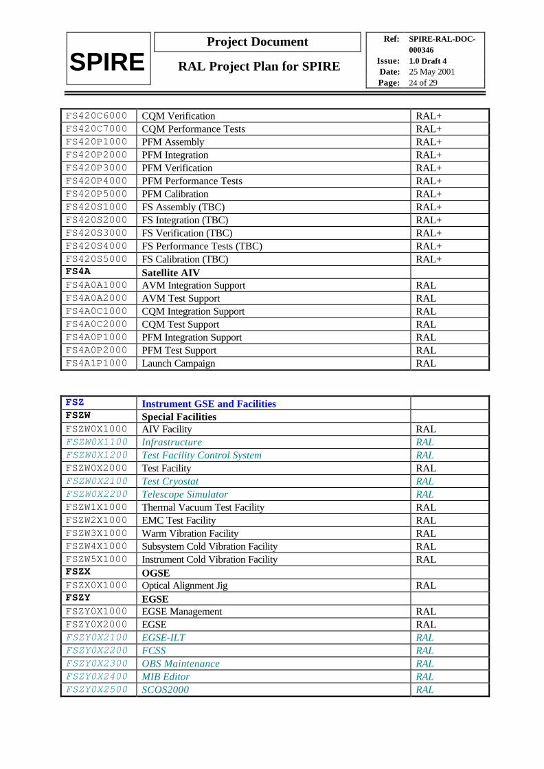
FS420C6000 CQM Verification RAL+FS420C7000 CQM Performance Tests RAL+FS420P1000 PFM Assembly RAL+FS420P2000 PFM Integration RAL+FS420P3000 PFM Verification RAL+FS420P4000 PFM Performance Tests RAL+FS420P5000 PFM Calibration RAL+FS420S1000 FS Assembly (TBC) RAL+FS420S2000 FS Integration (TBC) RAL+FS420S3000 FS Verification (TBC) RAL+FS420S4000 FS Performance Tests (TBC) RAL+FS420S5000 FS Calibration (TBC) RAL+FS4A Satellite AIVFS4A0A1000 AVM Integration Support RALFS4A0A2000 AVM Test Support RALFS4A0C1000 CQM Integration Support RALFS4A0C2000 CQM Test Support RALFS4A0P1000 PFM Integration Support RALFS4A0P2000 PFM Test Support RALFS4A1P1000 Launch Campaign RAL
FSZ Instrument GSE and FacilitiesFSZW Special FacilitiesFSZW0X1000 AIV Facility RALFSZW0X1100 Infrastructure RALFSZW0X1200 Test Facility Control System RALFSZW0X2000 Test Facility RALFSZW0X2100 Test Cryostat RALFSZW0X2200 Telescope Simulator RALFSZW1X1000 Thermal Vacuum Test Facility RALFSZW2X1000 EMC Test Facility RALFSZW3X1000 Warm Vibration Facility RALFSZW4X1000 Subsystem Cold Vibration Facility RALFSZW5X1000 Instrument Cold Vibration Facility RALFSZX OGSEFSZX0X1000 Optical Alignment Jig RALFSZY EGSEFSZY0X1000 EGSE Management RALFSZY0X2000 EGSE RALFSZY0X2100 EGSE-ILT RALFSZY0X2200 FCSS RALFSZY0X2300 OBS Maintenance RALFSZY0X2400 MIB Editor RALFSZY0X2500 SCOS2000 RAL

Ref: SPIRE-RAL-DOC-000346
Issue: 1.0 Draft 4Date: 25 May 2001Page: 25 of 29
Project Document
SPIRE RAL Project Plan for SPIRE
FSZY0X2600 CDMS Interface RAL
GFS Ground Segment Herschel SPIREGFS1 ICC DevelopmentGFS11 ManagementGFS11X1000 Support to ESAGFS11x2000 Control and Maintenance of ICC ScheduleGFS11X3000 Product AssuranceGFS11X4000 Team Setup and ManagementGFS12 Instrument OperationsGFS12X1000 Instrument Users ManualGFS12X2000 Instrument DatabaseGFS12X3000 Calibration DatabaseGFS12X4 Instrument ObservationsGFS12X4100 Instrument ModesGFS12X4210 Definition of AOTsGFS12X4220 Implementation of AOTsGFS12X4300 Operating ProceduresGFS13 Software DevelopmentGFS13X1000 Instrument Time EstimatorGFS13X2000 Instrument Command TranslatorGFS13X3000 RTA/QLAGFS13X4000 Trend AnalysisGFS13X5000 Calibration AnalysisGFS13X6000 Interactive analysisGFS13X7000 Science ProcessingGFS13X8000 Science AnalysisGFS13X9000 Diagnostic ToolsGFS2 ICC PreparationGFS21 PlanningGFS21X1000 SIPGFS21X2000 PV Phase TestingGFS21X3000 Science ValidationGFS21X4000 ICC DesignGFS22 ImplementationGFS22X1100 Operations Centre InfrastructureGFS22X1200 DAPSAS (UK) Centre InfrastructureGFS22X1300 DAPSAS (Fr) Centre InfrastructureGFS22X2100 Operations Centre HardwareGFS22X2200 DAPSAS (UK) Centre HardwareGFS22X2300 DAPSAS (Fr) Centre HardwareGFS22X3000 Commissioning Phase Equipment

Ref: SPIRE-RAL-DOC-000346
Issue: 1.0 Draft 4Date: 25 May 2001Page: 26 of 29
Project Document
SPIRE RAL Project Plan for SPIRE
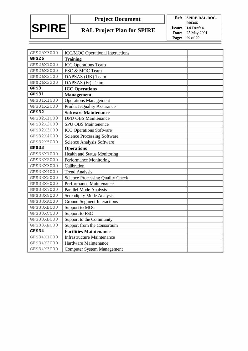
GFS22X4000 Instrument SimulatorGFS22X5000 DPU OBS Maintenance FacilityGFS22X6000 SPU OBS Maintenance FacilityGFS23 Integration and TestGFS23X1100 Operations Centre Integration and TestGFS23X1200 DAPSAS (UK) Centre Integration and TestGFS23X1300 DAPSAS (Fr) Centre Integration and TestGFS23X2000 ICC Internal InterfacesGFS23X3000 ICC Operations TestGFS23X4000 Herschel Ground Segment InteractionGFS24 FINDAS SupportGFS24X1000 FINDAS PrototypeGFS24X2000 FINDAS DevelopmentGFS25 Operations PlanningGFS25X1000 ICC Operations PlanGFS25X2000 ICC/FSC Operational InteractionsGFS25X3000 ICC/MOC Operational InteractionsGFS26 TrainingGFS26X1000 ICC Operations TeamGFS26X2000 FSC & MOC TeamGFS26X3100 DAPSAS (UK) TeamGFS26X3200 DAPSAS (Fr) TeamGFS3 ICC OperationsGFS31 ManagementGFS31X1000 Operations ManagementGFS31X2000 Product /Quality AssuranceGFS32 Software MaintenanceGFS32X1000 DPU OBS MaintenanceGFS32X2000 SPU OBS MaintenenceGFS32X3000 ICC Operations SoftwareGFS32X4000 Science Processing SoftwareGFS32X5000 Science Analysis SoftwareGFS33 OperationsGFS33X1000 Health and Status MonitoringGFS33X2000 Performance MonitoringGFS33X3000 CalibrationGFS33X4000 Trend AnalysisGFS33X5000 Science Processing Quality CheckGFS33X6000 Performance MaintenanceGFS33X7000 Parallel Mode AnalysisGFS33X8000 Serendipity Mode AnalysisGFS33XA000 Ground Segment InteractionsGFS33XB000 Support to MOCGFS33XC000 Support to FSCGFS33XD000 Support to the Community

Ref: SPIRE-RAL-DOC-000346
Issue: 1.0 Draft 4Date: 25 May 2001Page: 27 of 29
Project Document
SPIRE RAL Project Plan for SPIRE
GFS33XE000 Support from the ConsortiumGFS34 Facilities MaintenanceGFS34X1000 Infrastructure MaintenanceGFS34X2000 Hardware MaintenanceGFS34X3000 Computer System Management
FS11 ManagementFS110X1000 Support to ESA ****FS110X2000 Project Control RALFS110X3000 Product Assurance RALFS110X4000 Reviews ****
FSZY EGSEFSZY0X1000 EGSE UofSFSZY0X2000 Quick Look Facility RALFSZY0X3000 Digital Instrument Simulator IFSIFSZY0X4000 Analogue Instrument Simulator SApFSZY0X5000 Cold Instrument Simulator SApFSZY0X6000 FPU Simulator SApFSZX OGSEFSZX0X1000 Optical Alignment Jig RALFSZX0X2000 Throughput Detector Assembly QMWFSZW Special FacilitiesFSZW0X1000 AIV Facility RALFSZW0X2000 Calibration Facility RALFSZW0X3000 Thermal Vacuum Test Facility RALFSZW0X4000 EMC Test Facility SApFSZW0X5000 Cold Vibration FacilityFSZW0X6000 Warm Vibration Facility RAL
GFS Ground Segment Herschel SPIREGFS1 ICC DevelopmentGFS11 ManagementGFS11X1000 Support to ESAGFS11x2000 Control and Maintenance of ICC ScheduleGFS11X3000 Product AssuranceGFS11X4000 Team Setup and ManagementGFS12 Instrument OperationsGFS12X1000 Instrument Users ManualGFS12X2000 Instrument DatabaseGFS12X3000 Calibration Database

Ref: SPIRE-RAL-DOC-000346
Issue: 1.0 Draft 4Date: 25 May 2001Page: 28 of 29
Project Document
SPIRE RAL Project Plan for SPIRE
GFS12X4 Instrument ObservationsGFS12X4100 Instrument ModesGFS12X4210 Definition of AOTsGFS12X4220 Implementation of AOTsGFS12X4300 Operating ProceduresGFS13 Software DevelopmentGFS13X1000 Instrument Time EstimatorGFS13X2000 Instrument Command TranslatorGFS13X3000 RTA/QLAGFS13X4000 Trend AnalysisGFS13X5000 Calibration AnalysisGFS13X6000 Interactive analysisGFS13X7000 Science ProcessingGFS13X8000 Science AnalysisGFS13X9000 Diagnostic ToolsGFS2 ICC PreparationGFS21 PlanningGFS21X1000 SIPGFS21X2000 PV Phase TestingGFS21X3000 Science ValidationGFS21X4000 ICC DesignGFS22 ImplementationGFS22X1100 Operations Centre InfrastructureGFS22X1200 DAPSAS (UK) Centre InfrastructureGFS22X1300 DAPSAS (Fr) Centre InfrastructureGFS22X2100 Operations Centre HardwareGFS22X2200 DAPSAS (UK) Centre HardwareGFS22X2300 DAPSAS (Fr) Centre HardwareGFS22X3000 Commissioning Phase EquipmentGFS22X4000 Instrument SimulatorGFS22X5000 DPU OBS Maintenance FacilityGFS22X6000 SPU OBS Maintenance FacilityGFS23 Integration and TestGFS23X1100 Operations Centre Integration and TestGFS23X1200 DAPSAS (UK) Centre Integration and TestGFS23X1300 DAPSAS (Fr) Centre Integration and TestGFS23X2000 ICC Internal InterfacesGFS23X3000 ICC Operations TestGFS23X4000 Herschel Ground Segment InteractionGFS24 FINDAS SupportGFS24X1000 FINDAS PrototypeGFS24X2000 FINDAS DevelopmentGFS25 Operations PlanningGFS25X1000 ICC Operations PlanGFS25X2000 ICC/FSC Operational Interactions
Ref: SPIRE-RAL-DOC-000346
Issue: 1.0 Draft 4Date: 25 May 2001Page: 29 of 29
Project Document
SPIRE RAL Project Plan for SPIRE
GFS25X3000 ICC/MOC Operational InteractionsGFS26 TrainingGFS26X1000 ICC Operations TeamGFS26X2000 FSC & MOC TeamGFS26X3100 DAPSAS (UK) TeamGFS26X3200 DAPSAS (Fr) TeamGFS3 ICC OperationsGFS31 ManagementGFS31X1000 Operations ManagementGFS31X2000 Product /Quality AssuranceGFS32 Software MaintenanceGFS32X1000 DPU OBS MaintenanceGFS32X2000 SPU OBS MaintenenceGFS32X3000 ICC Operations SoftwareGFS32X4000 Science Processing SoftwareGFS32X5000 Science Analysis SoftwareGFS33 OperationsGFS33X1000 Health and Status MonitoringGFS33X2000 Performance MonitoringGFS33X3000 CalibrationGFS33X4000 Trend AnalysisGFS33X5000 Science Processing Quality CheckGFS33X6000 Performance MaintenanceGFS33X7000 Parallel Mode AnalysisGFS33X8000 Serendipity Mode AnalysisGFS33XA000 Ground Segment InteractionsGFS33XB000 Support to MOCGFS33XC000 Support to FSCGFS33XD000 Support to the CommunityGFS33XE000 Support from the ConsortiumGFS34 Facilities MaintenanceGFS34X1000 Infrastructure MaintenanceGFS34X2000 Hardware MaintenanceGFS34X3000 Computer System Management