project no. 1852 - houston no. 1852 table of contents ... material finer than no.200 sieve astm d...
TRANSCRIPT
Project No. 1852
TABLE OF CONTENTS
EXECUTIVE SUMMARY ............................................................................................................................................ I
1 INTRODUCTION ............................................................................................................................................. 1
1.1 PROJECT DESCRIPTION ....................................................................................................................................... 1
1.2 GEOTECHNICAL INVESTIGATION PROGRAM ............................................................................................................. 1
2 FIELD INVESTIGATION ................................................................................................................................... 2
2.1 GENERAL ......................................................................................................................................................... 2
2.2 GEOTECHNICAL BORINGS .................................................................................................................................... 2
2.3 SAMPLING METHODS ......................................................................................................................................... 3
2.4 SURVEY DATA ................................................................................................................................................... 3
3 LABORATORY TESTING .................................................................................................................................. 4
4 SUBSURFACE CONDITIONS ............................................................................................................................ 4
4.1 GENERAL GEOLOGY ........................................................................................................................................... 4
4.2 SOIL STRATIGRAPHY ........................................................................................................................................... 5
4.3 GROUNDWATER CONDITIONS .............................................................................................................................. 6
5 GEOTECHNICAL DESIGN AND RECOMMENDATIONS ...................................................................................... 6
5.1 GENERAL ......................................................................................................................................................... 6
5.2 FOUNDATION RECOMMENDATIONS ...................................................................................................................... 6
5.2.1 Floor Slab ................................................................................................................................................. 9
5.2.2 Grade Beams and Void Boxes .................................................................................................................. 9
5.2.3 Groundwater Control ............................................................................................................................. 10
5.3 DETENTION POND SLOPE STABILITY ANALYSES ...................................................................................................... 10
5.3.1 Slope Stability Analysis Design Factor of Safety ..................................................................................... 11
5.3.2 Results of Slope Stability Analysis .......................................................................................................... 12
5.3.3 Erosion Control Recommendations for the Slope ................................................................................... 12
6 PAVEMENT RECOMMENDATIONS ............................................................................................................... 14
6.1 SUBGRADE STABILIZATION ................................................................................................................................ 14
6.2 PAVEMENT .................................................................................................................................................... 14
7 CONSTRUCTION CONSIDERATIONS ............................................................................................................. 15
7.1 EARTHWORK AND FILL COMPACTION .................................................................................................................. 15
7.2 FOUNDATION EXCAVATION AND CONSTRUCTION ................................................................................................... 16
7.3 SITE DRAINAGE ............................................................................................................................................... 16
7.4 VEGETATION CONTROL..................................................................................................................................... 17
7.5 DESIGN REVIEW .............................................................................................................................................. 17
8 LIMITATIONS ............................................................................................................................................... 17
9 ILLUSTRATIONS ........................................................................................................................................... 18
SITE VICINITY PLAN ....................................................................................................................................................... 18
PLAN OF BORINGS ........................................................................................................................................................ 18
BORING LOGS .............................................................................................................................................................. 18
SYMBOLS AND TERMINOLOGY USED IN BORING LOGS .......................................................................................................... 18

Project No. 1852
PAVEMENT RECOMMENDATIONS .................................................................................................................................... 18
RESULTS OF SLOPE STABILITY ANALYSIS ............................................................................................................................ 18
LABORATORY TEST DATA SUMMARY SHEET ....................................................................................................................... 18
CONSOLIDATED UNDRAINED TEST REPORT ........................................................................................................................ 18

Project № 1852 Page i
EXECUTIVE SUMMARY
Kenall was retained by Huitt-Zollars to provide geotechnical services for the proposed buildings
improvements on Ardmore Street in Houston, Texas. The project consists of construction of new
buildings, associated pavement and detention pond. The project area is located at 7027
Ardmore Street in Houston, Texas.
The purpose of this study was to evaluate soil and groundwater conditions and to provide
design and construction recommendations for the buildings foundation and associated
pavement and detention pond. This study was performed in general accordance with Chapter
11 of the latest City of Houston's Public Works & Engineering Infrastructure Design Manual.
Based on the subsurface conditions revealed by the soil borings, the findings and
recommendations of this report are summarized below:
1. Subsurface soils at the site generally comprise of stiff to hard cohesive fat clays, lean
clays and clayey sand.
2. Groundwater was encountered at different depths for different boring locations.
3. Recommendations for foundation design.
4. Pavement design should generally be in accordance with the latest City of Houston
Standard Specification.
5. Recommendations detention pond should generally be in accordance with the latest
Harris County Flood Control District Standard Specification.
6. Proposed detention pond with a 4 horizontal to 1 vertical (4H:1V) slope is expected to be
stable for short term, long term and rapid drawdown conditions.
7. All excavation operations should be carried out in accordance with the latest City of
Houston Standard Specifications.
Please note that this executive summary does not fully relate our findings and opinions, which
are only presented through our full report.

Project No. 1852 Page 1
1 INTRODUCTION
1.1 Project Description
Kenall was retained by Huitt-Zollars to provide geotechnical services for the proposed buildings
improvements on Ardmore Street in Houston, Texas. The project consists of construction of new
buildings, associated pavement, and detention pond. The project area is located at 7027
Ardmore Street in Houston, Texas. A site vicinity map showing the approximate project location
is presented in illustration, Plate No.1 of this report.
The purpose of this study was to provide design and construction recommendations for the
proposed new buildings, associated parking, access driveway and detention pond. This study
was performed in general accordance with modified in Chapter 11 of the latest City of Houston's
Public Works & Engineering Infrastructure Design Manual.
1.2 Geotechnical Investigation Program
The primary objectives of this study were to gather information on subsurface conditions at the
site and to provide recommendations for the proposed buildings and the detention pond. The
objectives were accomplished by:
1. Drilling twenty-five (25) soil borings up to a depth of 35 feet below the existing subgrade
to determine soil stratigraphy and to obtain samples for laboratory testing;
2. Performing laboratory tests in accordance with ASTM methods to determine physical
and engineering characteristics of the soils;
3. Performing engineering analyses in accordance with the latest City of Houston Design
Manual-July 2015, to develop design guidelines and recommendations; and
4. Providing a geotechnical report that includes all the field data, laboratory data, and
geotechnical recommendations.
Subsequent sections of this report contain descriptions of the field exploration, laboratory testing
program, general subsurface conditions, design recommendations, and construction
considerations.

Project No. 1852 Page 2
2 FIELD INVESTIGATION
2.1 General
After obtaining clearance for the proposed boring in the field, borings were drilled to the
explored depths using a buggy rig. All drilling and sampling were performed in accordance with
appropriate ASTM procedures.
2.2 Geotechnical Borings
The field exploration program undertaken at the project site was performed in the months of
May 2014 and August 2014. B-1 through B-16 were drilled in the month of May 2014. B-17
through B-25 were drilled in the month of August of 2014. Subsurface conditions were
investigated by drilling twenty-five (25) soil borings (designated as B-1 through B-25) up to a
depth of 35 feet below the existing grade. Borings B-1 through B-6 were drilled to a depth of 35
feet. The test data from borings B-1 through B-6, were not considered for design purpose as the
borings were located outside the proposed building area. Borings B-7 through B-13 were drilled
to a depth of 5 feet; borings B-14 through B-19, B-24 and B-25 were drilled to a depth of 20 feet;
borings B-20 through B-23 were drilled to a depth of 30 feet. The approximate boring locations
are shown in Plate No. 2. Each sample in the field was removed from the sampler, examined
carefully, and then logged by an experienced soils technician. Portions of each sample were
sealed, packaged, and transported to our Kenall facility. Boreholes then backfilled with cement
bentonite grout using tremie method in accordance with latest City guidelines and patched at
the surface where applicable. Borings associated with each structure are shown in the below
Table 1.
Table 1: Boreholes location, proposed depth, proposed structure
Boring No. Boring Depth (ft) Proposed Structure
B-7 through B-13 5 Parking Lot, Driveway
B-14, B-15 and B-25 20 Detention Pond
B-16 20 Fueling Station
B-17 through B-19 20 Building 1
B-20 30 Building 1
B-21 through B-23 30 Building 2
B-24 20 Building 2
Detailed descriptions of the soils encountered in the borings are given in the boring logs
presented in Plate Nos.3 through 27. A key to the soils classification and symbols used in the
boring logs is also shown in Plate No.28.

Project No. 1852 Page 3
2.3 Sampling Methods
Soil samples were continuously obtained to the termination depth of the borings. Cohesive soil
samples were obtained with a three-inch thin-walled (Shelby) tube sampler in general
accordance with the ASTM D1587 standard. Cohesionless soil samples were obtained with a
Split Spoon Sampler. Each sample was removed from the sampler in the field, carefully
examined, and then classified. The shear strength of the cohesive soils was estimated by a
hand penetrometer in the field. Suitable portions of each sample were sealed and packaged for
transportation to our laboratory. Detailed descriptions of the soils encountered in the borings are
given in the boring logs presented in Plate Nos.3 through 27. A key to the soils classification and
symbols used in the boring logs is also shown in Plate No.28.
2.4 Survey Data
Based on the approximate survey information obtained from the google maps the location,
northing, easting, and termination depth for all the borings are presented as follows:
Table 1: Survey Data for all the Borings
Boring Number Northing (ft) Easting (ft)
Proposed Boring Depth (ft)
B-1 13818301.736 3118326.362 35
B-2 13818291.059 3118369.255 35
B-3 13818280.573 3118171.695 35
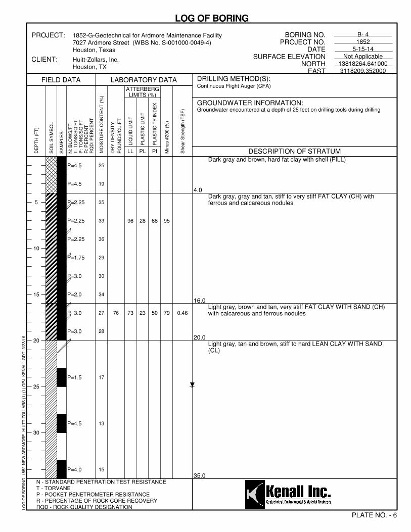
B-4 13818264.641 3118209.352 35
B-5 13818187.174 3118127.897 35
B-6 13818197.410 3118176.495 35
B-7 13818426.631 3118118.573 5
B-8 13818767.367 3118184.249 5
B-9 13818369.936 3118284.862 5
B-10 13818328.940 3118088.884 5
B-11 13818275.829 3118194.712 5
B-12 13818164.167 3118054.601 5
B-13 13818152.930 3118102.912 5
B-14 13818263.664 3118400.914 20
B-15 13818119.960 3118342.158 20
B-16 13818007.361 3118077.881 20
B-17 13818347.437 3118087.040 20
B-18 13818367.673 3118106.106 20
B-19 13818206.347 3118042.177 20
B-20 13818197.310 3118067.550 30
B-21 13818328.087 3118167.047 30
B-22 13818220.445 3118121.467 30
B-23 13818172.223 3118103.267 30
B-24 13818201.389 3118163.984 20

Project No. 1852 Page 4
B-25 13817989.676 3118340.795 20
3 LABORATORY TESTING
Selected soil samples were tested in the laboratory to determine applicable physical and
engineering properties. All tests except pocket penetrometer were performed according to the
relevant ASTM Standards. These tests consisted of Moisture Content, Material Finer than
No.200 Sieve, Liquid Limits and Plastic Limits, and Unconsolidated Undrained Triaxial
Compression Test and Consolidated Undrained Triaxial Test. The Atterberg Limits and percent
passing number 200 sieve tests were used to verify field classification by the ASTM version of the
Unified Soils Classification System. The unconsolidated undrained compression tests were
performed to obtain the undrained shear strength of the soil and consolidated undrained triaxial
tests were performed to obtain the cohesion and friction angle of the soil. The type and number
of tests performed for this investigation are summarized below:
Table 2: Laboratory Tests Performed
Test Name Test Method Number of Tests
Hand Penetrometer Not applicable
Moisture Content ASTM D 2216 285
Liquid Limits and Plastic Limits ASTM D 4318 49
Material Finer than No.200 Sieve ASTM D 1140 49
Unconsolidated Undrained Triaxial Compression Test ASTM D 2850 26
Consolidated Undrained Triaxial Test ASTM D 4767 1
4 SUBSURFACE CONDITIONS
4.1 General Geology
Two major surface geological formations that exist in the Houston area are the Beaumont
Formation and the Lissie Formation. The project area lies in the Beaumont Formation.
The Beaumont Formation dips southeastward and extends beneath beach sand and waters of the
Gulf of Mexico as far as the continental shelf. The courses of major streams and deltaic tributaries
changed frequently during the period of deposition, generating a complex stratification of sand,
silt, and clay deposits within the Beaumont clay. The Beaumont Formation was deposited on land
near sea level in flat river deltas and in inter-delta regions. Soil deposition occurred in fresh water
streams and in flood plains (as backwater marsh and natural levees). The clays and sands of the
Beaumont Formation are over-consolidated as a result of desiccation from frequent rising and
lowering of the sea level and the groundwater table. The clays of this formation have moderate to
high shear strength and relatively low compressibility. The sands of this formation are typically
very fine and often silty.

Project No. 1852 Page 5
4.2 Soil Stratigraphy
Our interpretation of soil and groundwater conditions at the project site is based on information
obtained at the boring locations only. This information has been used as the basis for our
conclusions and recommendations. Significant variations at areas not explored by the project
borings may require reevaluation of our findings and conclusions.
Boring No. & Depth Classification Description
STRATUM I
B-1, B-2, B-4, B-6, B-13, B-16, B-19 through B-24 (0-4 ft)
B-7 through B-12, B-14, B-15, B-17, B-18, B-25 (0-2 ft)
B-3 (0-8 ft), B-5 (0-6 ft)
FILL Dark gray, gray, brown and tan, sandy fat clay and sandy lean clay with shell and gravel- FILL
STRATUM II
B-1 and B-2 (4-18 ft)
B-3 (8-25 ft)
B-4, B-6, B-16, B-19, B-20, B-24 (4-20 ft)
B-5 (6-20 ft)
B-7 through B-12 (2-5 ft)
B-13 (4-5 ft)
B-14, B-15, B-17, B-18, B-25, (2-20 ft)
B-20 (4-23 ft)
B-21, B-22 (4-25 ft)
B-23 (4 - 30 ft)
CH Dark gray, light
gray, gray, reddish
brown, yellowish
brown and tan, stiff
to hard Fat Clay
(CH)
Stratum III
B-1 and B-2 (18-30 ft)
B-3 (25-35 ft)
B-4, B-5, B-6 (20-35 ft)
B-20 (23-30 ft)
B-21, B-22 (25-30 ft)
CL Light gray, gray,
reddish brown and
tan, stiff to hard
Sandy Lean Clay
and Lean Clay with
Sand (CL)
Project No. 1852 Page 6
Stratum IV
B-1, B-2 (30-35 ft)
SILTY SAND
CLAYEY
SAND
Light gray and
brown, dense Silty
Sand (SM) and
Clayey Sand (SC)
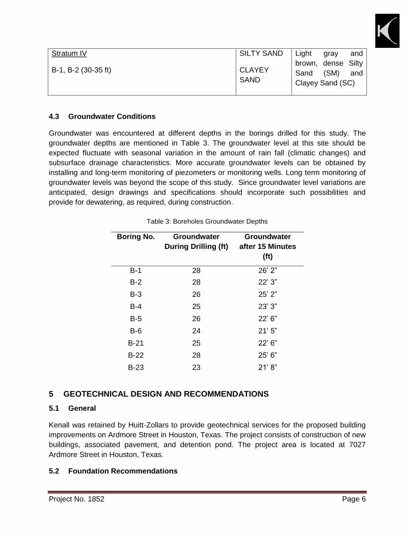
4.3 Groundwater Conditions
Groundwater was encountered at different depths in the borings drilled for this study. The
groundwater depths are mentioned in Table 3. The groundwater level at this site should be
expected fluctuate with seasonal variation in the amount of rain fall (climatic changes) and
subsurface drainage characteristics. More accurate groundwater levels can be obtained by
installing and long-term monitoring of piezometers or monitoring wells. Long term monitoring of
groundwater levels was beyond the scope of this study. Since groundwater level variations are
anticipated, design drawings and specifications should incorporate such possibilities and
provide for dewatering, as required, during construction.
Table 3: Boreholes Groundwater Depths
Boring No. Groundwater
During Drilling (ft)
Groundwater
after 15 Minutes
(ft)
B-1 28 26’ 2”
B-2 28 22’ 3”
B-3 26 25’ 2”
B-4 25 23’ 3”
B-5 26 22’ 6”
B-6 24 21’ 5”
B-21 25 22’ 6”
B-22 28 25’ 6”
B-23 23 21’ 8”
5 GEOTECHNICAL DESIGN AND RECOMMENDATIONS
5.1 General
Kenall was retained by Huitt-Zollars to provide geotechnical services for the proposed building
improvements on Ardmore Street in Houston, Texas. The project consists of construction of new
buildings, associated pavement, and detention pond. The project area is located at 7027
Ardmore Street in Houston, Texas.
5.2 Foundation Recommendations

Project No. 1852 Page 7
Based on soil conditions encountered in soil boring and our experience with the general area soils
we recommend supporting proposed building on drilled and underreamed piers.
A grading plan was not available during writing this report. For the purpose of writing this report
we have assumed nominal cuts and fills are required to achieve the final grades. The following
design recommendations were developed assuming the existing grade was within 2 ft of final
grade.
Building 1 (Borings B-17 through B-20) and Building 2 (Borings B-21 through B-24)
Drilled and Underreamed Piers
Based on soil conditions encountered in the borings the proposed building could be
supported on drilled and underreamed piers bearing at a depth of at least twenty feet (20)
below existing grade or final grade, whichever is deep. Based on our experience with
general area soils, granular soils and groundwater seepage could be encountered during
construction of underreamed piers. Some adjustments in depth of piers may be required in
some areas of the site to bear the bottom of the underream above any granular soils and/or
groundwater seepage. Kenall should observe the adjustments in pier depths in field.
Piers bearing at above depths may be sized for a net allowable bearing pressure of 3,500
psf for dead load plus sustained live load and 4,500 psf for total load conditions, whichever
governs. These allowable bearing pressures contain factors of safety of about 3 and 2,
respectively.
The minimum clear spacing between edges of adjacent piers should be at least one (1)
underream diameter. Based on experience with the general area soils underreams can be
successfully installed with a bell to shaft ratio of at least 2 and not exceeding 3. Piers
designed using the recommended allowable bearing capacity will experience small
settlements (less than 1 inch) that will be well within the tolerable limits for the proposed
structure. Differential settlements should be on the order of one-half the total settlement.
The portion of the shaft in expansive soils within the depth of moisture change
(approximately 8 ft below ground surface) could be subjected to uplift forces (soil-to-pier
adhesion) caused by potential soil swell. In addition, the piers could be subjected to other
uplift forces (tensile forces) due to the super structure. The pier shaft should be reinforced
with sufficient tension steel over its entire length to resist these potential uplift forces
(tensile forces) caused by swelling soils and superstructures. The uplift forces due to
swelling soils should be resisted by the underreamed portion of the pier that acts as an
anchor. Underreamed piers should be reinforced with sufficient tension steel over its entire
length to resist potential uplift forces (tensile forces). Foundation reinforcement design will
be the responsibility of Project Structural Engineer.
Caving of shaft may occur during construction of the drilled piers due to calcareous nodules
and ferrous nodules and groundwater seepage that could be encountered at bearing depth
during construction. In order to minimize the possibility of shaft caving during drilled pier
construction, the construction contractor should be prepared to use slurry method of drilling
Project No. 1852 Page 8
or to use cased piers or straight sided shaft foundations. We recommend that the drilling be
performed under the supervision of a licensed Professional Engineer.
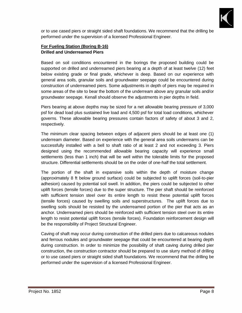
For Fueling Station (Boring B-16)
Drilled and Underreamed Piers
Based on soil conditions encountered in the borings the proposed building could be
supported on drilled and underreamed piers bearing at a depth of at least twelve (12) feet
below existing grade or final grade, whichever is deep. Based on our experience with
general area soils, granular soils and groundwater seepage could be encountered during
construction of underreamed piers. Some adjustments in depth of piers may be required in
some areas of the site to bear the bottom of the underream above any granular soils and/or
groundwater seepage. Kenall should observe the adjustments in pier depths in field.
Piers bearing at above depths may be sized for a net allowable bearing pressure of 3,000
psf for dead load plus sustained live load and 4,500 psf for total load conditions, whichever
governs. These allowable bearing pressures contain factors of safety of about 3 and 2,
respectively.
The minimum clear spacing between edges of adjacent piers should be at least one (1)
underream diameter. Based on experience with the general area soils underreams can be
successfully installed with a bell to shaft ratio of at least 2 and not exceeding 3. Piers
designed using the recommended allowable bearing capacity will experience small
settlements (less than 1 inch) that will be well within the tolerable limits for the proposed
structure. Differential settlements should be on the order of one-half the total settlement.
The portion of the shaft in expansive soils within the depth of moisture change
(approximately 8 ft below ground surface) could be subjected to uplift forces (soil-to-pier
adhesion) caused by potential soil swell. In addition, the piers could be subjected to other
uplift forces (tensile forces) due to the super structure. The pier shaft should be reinforced
with sufficient tension steel over its entire length to resist these potential uplift forces
(tensile forces) caused by swelling soils and superstructures. The uplift forces due to
swelling soils should be resisted by the underreamed portion of the pier that acts as an
anchor. Underreamed piers should be reinforced with sufficient tension steel over its entire
length to resist potential uplift forces (tensile forces). Foundation reinforcement design will
be the responsibility of Project Structural Engineer.
Caving of shaft may occur during construction of the drilled piers due to calcareous nodules
and ferrous nodules and groundwater seepage that could be encountered at bearing depth
during construction. In order to minimize the possibility of shaft caving during drilled pier
construction, the construction contractor should be prepared to use slurry method of drilling
or to use cased piers or straight sided shaft foundations. We recommend that the drilling be
performed under the supervision of a licensed Professional Engineer.

Project No. 1852 Page 9
5.2.1 Floor Slab
As discussed in Section 4.2 of this report, the onsite soils consist of fat clay material
within the depth of seasonal moisture change. The fat clay soils encountered within the
depth of moisture change can shrink-swell with seasonal variation in moisture changes.
Any Grade-supported floor slabs placed on these soils will incur risk associated with
distress.
Potential Vertical Slab Movements: Based on the information obtained during this
investigation, a slab constructed on-grade will be subjected to potential vertical slab
movements of about 4.96 inches. The PVR values were estimated for this site using the
Texas Department of Transportation method (Test Procedure TEX-124-E). One (1) inch
of PVR is generally accepted as the maximum allowable value for design and
construction in the geographical area.
Subgrade Treatment: The extent of subgrade treatment depends on the allowable PVR
as determined by the structural engineer. The table below provides the details of
allowable PVR and respective thickness of select fill required.
Allowable PVR (inches) Thickness of Select Fill Required (inches)
3.26 48
0.95 96
In areas where less than the above specified thickness of fill (based on the allowable
PVR) is required to bring the building pad to grade, we recommend that the existing soils
be excavated to the recommended depth of subgrade treatment below the top of the
finished building pad subgrade and replaced with select fill. Subgrade treatment should
extend at least 4-feet horizontally beyond the perimeter of the building.
In view of above discussion, we recommend to replace the existing fill material with non-
expansive material (structural fill). The structural fill material should be installed below
the bottom of floor slabs and top of surface of underlying soil. The select material
(structural fill) should extend at least 4 ft beyond the exterior walls. Requirements for
select, non-expansive material (structural fill) are discussed in Section 6.1 of this report
5.2.2 Grade Beams and Void Boxes
The excavations for the grade beams should be clean and free of any loose materials
prior to concrete placement. A void space of six (6) inches should be provided beneath
the bottom of grade beams. This void space allows for movement of the expansive soils
below the grade beams without distressing the structural system. Structural cardboard
void forms are often used to provide this void space.

Project No. 1852 Page 10
Void Boxes are typically placed under the grade beams to provide the void space, and
act as a barrier separating the grade beams from the underlying soils. The void boxes
collapse when the underlying soils swell, thus minimizing the uplift loads caused by the
expansive soils on grade beams. However, in some cases these voids may act as a
channel for water to travel under a foundation system with poor area drainage. If this
condition exists, it may result in higher seasonal movements than predicted in this report
and may cause distress to floor slab. Close attention should be exercised during
construction of these voids.
It is our opinion that the determination whether or not to provide voids under the grade
beams be made after both the positive and negative aspects are evaluated. Kenall from
our experience with these voids, as well as the experiences of other experts, brings us to
the conclusion that even though they may be effective in reducing swell pressures on the
grade beams, they may provide free water which would be available for absorption by
slab support soils.
5.2.3 Groundwater Control
Groundwater was encountered on drilling tools during drilling operations. Based on our
experience seasonal groundwater seepage could be encountered during excavation for
foundations and utility conduits. In cohesive soils groundwater may be collected in the
excavated bottom sumps for pump disposal. In semi cohesion less soils or granular soils
dewatering will be required. In such cases groundwater typically controlled by installation
of vacuum well points for excavation generally shallower than 15 feet or deep wells with
submersible pumps for excavation deeper than 15 feet. The groundwater level in these
soils should be lowered and maintained at least 5 feet below the level of excavation.
It is recommended that the actual groundwater conditions be verified by the
contractor at the time of construction and that groundwater control be performed in
general accordance with the latest City of Houston Standard Specifications.
5.3 Detention Pond Slope Stability Analyses
The detention pond is proposed to be about 5 feet deep, and will have grass-lined side slopes
with inclination of 4 horizontal to 1 vertical (4H:1V). Borings B-14, B-15 and B-25 were drilled at
the detention pond location. We conducted slope stability analyses using information from the
borings and assuming some parameters based on similar soil conditions to evaluate the slope
stability of the earth slopes using Morgenstern-price Method. The computer program SLOPE/W
version 8.14.2.11317 developed by GEO-SLOPE International. The SLOPE/W version
8.14.2.11317 computer program searches for the critical slope failure plane and computes
the minimum factor of safety for the given slope geometry and subsurface soil conditions.
For the slope stability analysis, three conditions were analyzed. The three different conditions
are:

Project No. 1852 Page 11
Short Term or Undrained Condition – This condition occurs when the pore pressures within
the soil mass are not dissipated. Typically, this condition corresponds to the state of the soils,
which exist immediately after performing any cut/fill during the construction of any slope. For
this condition slopes were analyzed using undrained soil parameters obtained from our
laboratory testing program.
Long Term or Drained Condition - This condition occurs when the pore pressures within the
soil mass are dissipated. Typically, this condition corresponds to the state of the soils a few
months or years after the construction are completed. For this condition, slopes were analyzed
using drained or effective stress soil parameters obtained from results of laboratory testing. In
the long term condition, the slope analyzed consisted of consolidated and drained condition and
effective shear strength parameters prevail. Due to the expansive soil conditions within the
active zone, the mobilized shear strength parameters were used.
Rapid Drawdown Condition - This condition occurs when the water level in the ponds rises
during a flood saturating the slope and then drains rapidly or suddenly lowers after the flood
recedes. The state of stress within the soils of the slope after a flood event depends largely on
the permeability and drainage characteristics of the slope. When the water levels are lowered
rapidly or suddenly, against a clay slope, excess pore pressures may not have enough time to
dissipate and an undrained strength analysis is required. For this condition, slopes were
analyzed using total stress soil parameters obtained from results of laboratory testing.
Expansive soil conditions were encountered at the site. Due to the expansive soil conditions
within the active zone, the mobilized shear strength parameters were used.
5.3.1 Slope Stability Analysis Design Factor of Safety
Minimum acceptable factors of safety against slope stability failures used in this
reports are provided in Table 4 below.
Table 4: Minimum Acceptable Factor of Safety for Slope Stability Analyses
Condition Minimum Acceptable Factor of Safety
Short term condition 1.30
Long term condition 1.50
Rapid drawdown condition 1.25
The above factor of safety either meets or exceeds the minimums recommended by the
Harris County Flood Control District Guidelines. A safety factor of 1.0 indicates
impending failure. The larger the safety factor above 1.0, the lower the risk that the
slope will fail. As a practical matter, and in consideration of the variables and unknowns
involved, the risk cannot be reduced to zero. The goal is to reduce the risk of slope
failure to a reasonable and acceptable level, with due consideration of the
consequences of failure.

Project No. 1852 Page 12
5.3.2 Results of Slope Stability Analysis
The shear strengths of soils were conservatively estimated based on results of
laboratory tests performed during the past study. Shear strength parameters used in the
stability analyses are tabulated below:
Table 5: Soil Strength Parameters used in Slope Stability Analyses
Depth (ft)
Material Unit Weight (pcf)
Short-Term Long-Term (assumed)
Rapid Drawdown (assumed)
C, psf Φ’, deg C’, psf Φ’, deg C’, psf Φ’, deg
0-20 Fat Clay (CH)
125 1000 0 300 12 500 8
Slope stability analyses were performed on the 1V:4H slope. Slope stability analyses
were performed using the soil profile defined by soil borings B-14, B-15, and B-25.
These analyses were performed in order to determine the factors of safety of the existing
slope of the bank against slope stability failure. The results of our slope stability
analysis are shown in Plate No 30 through 32 and the factors of safety are provided in
Table 6 below.
Table 6: Results of Slope Stability Analysis for the proposed Slope
Condition
Minimum Factor of Safety Against Slope Stability Failure
Short term
conditions
Long term
condition
Rapid drawdown
condition
Plate Nos.
Proposed Slope
3.807 1.500 2.065 30, 31, 32
Based on results from our slope stability analysis the pond slopes have adequate safety
factor against stability failure. 4H:1V earth slopes for the proposed 10 feet deep
Detention Pond, constructed in Borings B-14, B-15 and B-25 soil stratigraphy, will
posses adequate factor of safety against slope instability in terms of short and long term
and the rapid drawdown loading conditions.
5.3.3 Erosion Control Recommendations for the Slope
If any sandy or loose soils are encountered, these soils may trigger slope failures due to
erosion. Therefore, we recommended that proper erosion control measures be provided.
The following recommendations should be used for erosion control of exposed
sandy, dispersive or loose soils on the slopes.
Erosion Control Recommendations- Using Clay liner and Vegetation
The high erosion potential that could result due to the exposure of the slope may
be controlled by using clay liner and vegetation. It is recommended that the

Project No. 1852 Page 13
following procedures be performed in order to control the erosion of exposed
soils and minimize the potential for slope stability failure of the proposed
detention pond.
Prepare the subgrade in accordance with Section 6.1
Over-excavate any exposed sands and as well as for a width of at least 20
feet from the top-of-slopes and replace with at least 2 feet of the lean clays
(PI > 20) and fat clays (measured perpendicular to the exposed surface),
placed under controlled conditions (i.e., in 6-inch compacted lifts at a
minimum of 95% of the maximum dry density of the soil in accordance with
standard compaction procedures (ASTM D 698) within ± 2% of optimum
moisture content).
Place at least 3 inches of topsoil over the bottom, side slopes, and for a width
of 20 feet from the top of the slopes.
Provide erosion control measures by immediately initiating vegetative growth.
Erosion Control Recommendations- Using Rip–Rap
Riprap may be used for erosion control of the exposed slope. If used, it is
recommended that the following procedures be performed for erosion control.
Provide riprap consisting of broken concrete or stone. Provide riprap that is
dense, durable and hard material free from cracks, seams and other defects
which would increase deterioration from handling and natural causes.
Provide riprap in cubic form.
Place the riprap on the slopes, to establish a well graded mass of riprap with
minimal voids.
Erosion control Recommendations- Using Geosynthetics
Geosynthetics can also be used for erosion control of the exposed sands and
minimize the potential for slope stability failure of the slope. If used, it is
recommended that the following procedures be performed for erosion control.
Prepare the subgrade in accordance with Section 6.1 and as necessary to
allow placement of a geosynthetic lining system
Place the geosynthetic lining such as the Enkamat 7910, or equivalent,
should be placed in accordance with the manufacturer's recommended
installation guidelines.
Place at least 6 inches of topsoil over the geosynthetic lining.
Once the geosynthetic lining system is installed, vegetative growth should be initiated by hydro mulching or hydro seeding.

Project No. 1852 Page 14
6 PAVEMENT RECOMMENDATIONS
As discussed previously the pavement for the project could consist of either asphalt concrete or
Portland cement concrete. Detailed pavement recommendations are provided in sections below.
6.1 Subgrade Stabilization
Paving areas should be proof-rolled to check for any soft or weak areas. Any soft or weak areas
observed during the proof-rolling process should be removed and replaced with engineered fill
or structural fill as discussed in Section 6.1 of this report.
After proof-rolling the exposed surface of pavement areas should be stabilized using lime. The
upper 8 inches of exposed final subgrade should be stabilized by the addition of 7.0% lime. This
would require about 42 pounds of lime per square yard, based on subgrade thickness of 8 inches
and a soil dry unit weight of 100 pounds per cubic foot (pcf). The actual percentage of lime
should be confirmed by laboratory tests.
The lime stabilization of clay subgrade should be performed in accordance with latest City of
Houston Standard Specifications for "lime stabilized subgrade".
6.2 Pavement
The assumptions utilized in our pavement thickness analysis are summarized on Plate No. 29.
The following pavement thicknesses are based on these assumptions and procedures
published by the Portland Cement Association and the National Crushed Stone Association.
Recommendations for material properties for the paving layers are provided on Plate No. 29. It
is estimated that the service life for a properly constructed and maintained pavement will be in
order of 50 years. Proper civil design features such as joint design, quantity shoulder support
should be incorporated into the plans and specifications.
Parking Lots - Automobile Only
(DI-1)
Flexible Base Rigid Pavement
1.5" Hot Mix Asphaltic Concrete 5.0" Reinforced Concrete
6.0" Crushed Limestone* 8.0" Stabilized Compacted Subgrade
8.0" Stabilized Compacted Subgrade
Parking Lots & Light Duty Access Lanes
(DI-2)
Flexible Base Rigid Pavement
2.0" Hot Mix Asphaltic Concrete 6.0" Reinforced Concrete
8.0" Crushed Limestone* 8.0" Stabilized Compacted Subgrade
8.0" Stabilized Compacted Subgrade
Project No. 1852 Page 15
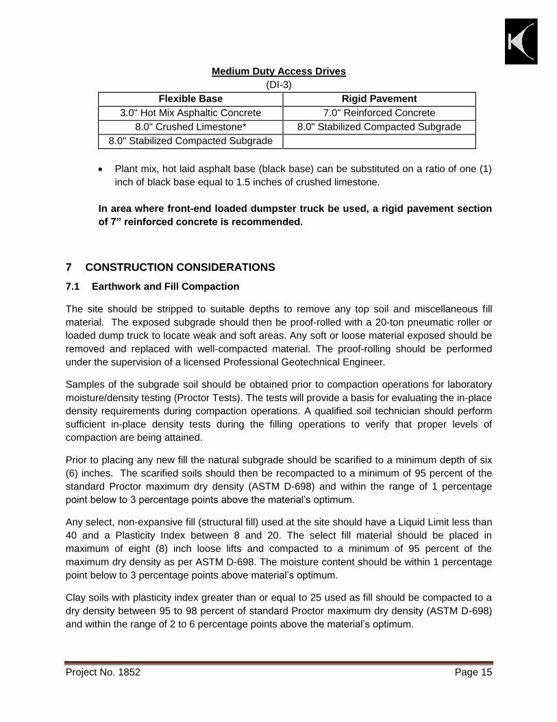
Medium Duty Access Drives
(DI-3)
Flexible Base Rigid Pavement
3.0" Hot Mix Asphaltic Concrete 7.0" Reinforced Concrete
8.0" Crushed Limestone* 8.0" Stabilized Compacted Subgrade
8.0" Stabilized Compacted Subgrade
Plant mix, hot laid asphalt base (black base) can be substituted on a ratio of one (1)
inch of black base equal to 1.5 inches of crushed limestone.
In area where front-end loaded dumpster truck be used, a rigid pavement section
of 7” reinforced concrete is recommended.
7 CONSTRUCTION CONSIDERATIONS
7.1 Earthwork and Fill Compaction
The site should be stripped to suitable depths to remove any top soil and miscellaneous fill
material. The exposed subgrade should then be proof-rolled with a 20-ton pneumatic roller or
loaded dump truck to locate weak and soft areas. Any soft or loose material exposed should be
removed and replaced with well-compacted material. The proof-rolling should be performed
under the supervision of a licensed Professional Geotechnical Engineer.
Samples of the subgrade soil should be obtained prior to compaction operations for laboratory
moisture/density testing (Proctor Tests). The tests will provide a basis for evaluating the in-place
density requirements during compaction operations. A qualified soil technician should perform
sufficient in-place density tests during the filling operations to verify that proper levels of
compaction are being attained.
Prior to placing any new fill the natural subgrade should be scarified to a minimum depth of six
(6) inches. The scarified soils should then be recompacted to a minimum of 95 percent of the
standard Proctor maximum dry density (ASTM D-698) and within the range of 1 percentage
point below to 3 percentage points above the material’s optimum.
Any select, non-expansive fill (structural fill) used at the site should have a Liquid Limit less than
40 and a Plasticity Index between 8 and 20. The select fill material should be placed in
maximum of eight (8) inch loose lifts and compacted to a minimum of 95 percent of the
maximum dry density as per ASTM D-698. The moisture content should be within 1 percentage
point below to 3 percentage points above material’s optimum.
Clay soils with plasticity index greater than or equal to 25 used as fill should be compacted to a
dry density between 95 to 98 percent of standard Proctor maximum dry density (ASTM D-698)
and within the range of 2 to 6 percentage points above the material’s optimum.

Project No. 1852 Page 16
Sandy clay soils with a plasticity index less than 25 used a fill should be compacted to at least
95 percent of standard Proctor maximum dry density (ASTM D-698) and within the range of 1
percentage point below to 3 percentage points above the material’s optimum.
7.2 Foundation Excavation and Construction
The foundation excavations should be inspected under the supervision of a licensed
Professional Geotechnical Engineer to confirm that the bearing soils are similar to those
encountered in our field exploration and that the foundation areas have been properly prepared.
The geotechnical engineer should be immediately notified should any subsoil conditions be
uncovered that will alter the conclusions and recommendations contained in this report. Further
investigation and supplemental recommendations may be required if such a condition is
encountered.
For drilled piers, the concrete should be placed in a timely manner after drilling to minimize the
potential for caving of the foundation soils. Piers should not be poured without the prior
approval of a licensed Professional Geotechnical Engineer. Prior to placement of concrete, the
foundations excavations should be inspected to verify that:
1. The foundations bear in the proper bearing strata. 2. The drilled shaft is to the proper dimensions and reinforcing steel is placed as shown
on the structural drawings. 3. The shaft has been drilled plumb within specified tolerances. 4. Excessive cutting, buildup of cutting, and any other soft compressible materials have
been removed from the bottom of the excavations. 5. Any groundwater seepage observed in the pier excavations and sloughing of soils
has been handled properly.
Based on experience with the general area soils underreams can be successfully installed with
a bell to shaft ratio of at least 2 and not exceeding 3. If the underreams are unstable or
marginally stable with 3:1 bell to shaft ratio, the bell to shaft ration can be changed by increasing
the shaft diameter. If the soil conditions warrant the changing of the shaft diameter, the
Structural Engineer of record should be informed about any changes because they may require
a change in reinforcing steel or bell diameter.
Excavations adjacent to existing buildings could cause ground displacement and movement of
an adjacent structure. Also, new construction can cause damage to adjacent building due to
vibrations caused by the construction traffic or equipment. A monitoring program should be
established during the construction phase of phase of the project.
7.3 Site Drainage
It is recommended that site drainage be well developed. Drainage is important from the
standpoint of soil stability. Surface water should be directed away from the foundation soils (use
a minimum slope of 5% within 10 feet of foundation). No ponding of surface water should be
allowed near the structure. Good drainage should be provided not only under the structure, but
the general area should be well drained.
Project No. 1852 Page 17
7.4 Vegetation Control
We recommend trees not to be closer than half the canopy diameter of mature trees from the
structure, typically a minimum of 20 feet. This will minimize possible foundation settlement
caused by the tree root systems.
7.5 Design Review
Review of the design and construction plans as well as the specifications should be performed
by Kenall before release. The review is aimed at determining if the geotechnical design
recommendations and construction criteria presented in this report have been properly
interpreted. Design review is not within the scope of work authorized in this study. Should you
elect to retain Kenall to perform a design review, additional fees would be applicable.
8 LIMITATIONS
This report was prepared for the exclusive use of the Huitt-Zollars, Inc. and City of
Houston, for specific application to the construction of the referenced project at the
aforementioned location in Houston, Texas. Our report was prepared in accordance with
generally accepted geotechnical engineering practice common to the local area. No other
warranty, express or implied, is made.
The analyses and recommendations contained in this report are based on the data obtained
from the referenced subsurface exploration. The boring indicates subsurface conditions only at
the specific locations and times, and only to the depths penetrated. The boring does not
necessarily reflect strata variations that may exist in subsurface conditions within the site. The
validity of the recommendations is based in part on assumptions about the stratigraphy made by
the Geotechnical Engineer. Such assumptions may be confirmed only during earthwork and
construction. If subsurface conditions different from those described are noted during
construction, recommendations in this report must be reevaluated.
If any changes in the nature, design, or location of the project are planned, the conclusions and
recommendations contained in this report should not be considered valid unless the changes
are reviewed and conclusions of this report are modified or verified in writing by Kenall. Kenall is
not responsible for any claims, damages, or liability associated with interpretation of subsurface
data, reuse of the subsurface data, or engineering analyses without expressed written
authorization of Kenall.

Project No. 1852 Page 18
9 ILLUSTRATIONS
Description: Plate No.
Site Vicinity Plan 1
Plan of Borings 2
Boring Logs 3 through 27
Symbols and Terminology used in Boring Logs 28
Pavement Recommendations 29
Results of Slope Stability Analysis 30 through 32
Laboratory Test Data Summary Sheet 33 through 38
Consolidated Undrained Test Report 39
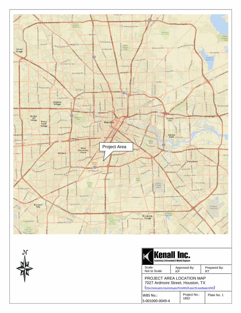
Scale: Not to Scale
Approved By: KP
Prepared By: RT
Approved By: KP PROJECT AREA LOCATION MAP
7027 Ardmore Street, Houston, TX (http://www.gims.houstontx.gov/PortalWS/R.aspx?M.aspx&app=GIMS)
Project No.: 1852
Plate No. 1 WBS No.:
S-001000-0049-4
Project Area

E;...��
1.1
N
\ Scale: Approved By: Not to Scale KP
PLAN OF BORINGS 7027 Ardmore Street Houston, Texas
WBS No. S-001000-0049-4 Project No.:
1852
\ I \ \ I \
\
Prepared By: RT
Plate No. 2

26
24
15
63
50
31
95
93
85
1.1
1.72
34
30
27
35
32
30
31
32
22
22
14
15
17
P=1.75
P=3.5
P=4.25
P=1.0
P=2.25
P=3.5
P=3.25
P=2.75
P=3.0
P=2.5
P=3.75
P=4.5
N=32
91
110
89
74
46
Dark gray and brown, stiff fat clay with shell (FILL)
Dark gray, gray and tan, stiff to very stiff FAT CLAY (CH) withferrous nodules
Light gray, brown and tan, very stiff to hard LEAN CLAY (CL) withcalcareous and ferrous nodules
Light gray and brown, dense SILTY SAND (SM)
4.0
18.0
30.0
35.0
Min
us #
200 (
%)
ATTERBERGLIMITS (%)
N - STANDARD PENETRATION TEST RESISTANCET - TORVANEP - POCKET PENETROMETER RESISTANCER - PERCENTAGE OF ROCK CORE RECOVERYRQD - ROCK QUALITY DESIGNATION
5
10
15
20
25
30
Shear
Str
ength
(T
SF
)
LABORATORY DATA
PLATE NO. - 3
DRILLING METHOD(S):
PL PI
BORING NO.PROJECT NO.
DATESURFACE ELEVATION
NORTHEAST
GROUNDWATER INFORMATION:
B- 11852
5-15-14Not Applicable
13818301.7360003118326.362000
DR
Y D
EN
SIT
Y
PO
UN
DS
/CU
.FT
SO
IL S
YM
BO
L
CLIENT:
PROJECT:
DESCRIPTION OF STRATUM
Groundwater encountered at a depth of 28 feet on drilling tools during drilling
N: B
LO
WS
/FT
T: T
ON
S/S
Q F
TP
: T
ON
S/S
Q F
TR
: P
ER
CE
NT
RQ
D: P
ER
CE
NT
LIQ
UID
LIM
IT
1852-G-Geotechnical for Ardmore Maintenance Facility7027 Ardmore Street (WBS No. S-001000-0049-4)Houston, Texas
Huitt-Zollars, Inc.Houston, TX
FIELD DATA
SA
MP
LE
S
MO
IST
UR
E C
ON
TE
NT
(%
)
Continuous Flight Auger (CFA)
LL
LOG OF BORING
PLA
ST
IC L
IMIT
PLA
ST
ICIT
Y IN
DE
X
DE
PT
H (
FT
)
LO
G O
F B
OR
ING
1
85
2-N
EW
AR
DM
OR
E-
HU
ITT
ZO
LL
AR
S (
1)
(1).
GP
J
KE
NA
LL
.GD
T
3/2
3/1
6

29
19
14
59
50
25
95
93
73 0.65
38
34
31
30
32
27
30
30
24
22
13
15
21
P=1.75
P=2.0
P=3.0
P=3.5
P=3.5
P=3.25
P=3.0
P=3.0
P=2.75
P=2.5
P=4.5
P=4.5
N=22
104
88
69
39
Dark gray and brown, stiff fat clay with shell (FILL)
Dark gray, gray and tan, very stiff FAT CLAY (CH) with ferrous andcalcareous nodules
Light gray, brown and tan, very stiff to hard LEAN CLAY WITHSAND (CL) with calcareous and ferrous nodules
Light gray and brown, medium dense SILTY SAND (SM)
4.0
18.0
30.0
35.0
Min
us #
200 (
%)
ATTERBERGLIMITS (%)
N - STANDARD PENETRATION TEST RESISTANCET - TORVANEP - POCKET PENETROMETER RESISTANCER - PERCENTAGE OF ROCK CORE RECOVERYRQD - ROCK QUALITY DESIGNATION
5
10
15
20
25
30
Shear
Str
ength
(T
SF
)
LABORATORY DATA
PLATE NO. - 4
DRILLING METHOD(S):
PL PI
BORING NO.PROJECT NO.
DATESURFACE ELEVATION
NORTHEAST
GROUNDWATER INFORMATION:
B- 21852
5-15-14Not Applicable
13818291.0590003118369.255000
DR
Y D
EN
SIT
Y
PO
UN
DS
/CU
.FT
SO
IL S
YM
BO
L
CLIENT:
PROJECT:
DESCRIPTION OF STRATUM
Groundwater encountered at a depth of 28 feet on drilling tools during drilling
N: B
LO
WS
/FT
T: T
ON
S/S
Q F
TP
: T
ON
S/S
Q F
TR
: P
ER
CE
NT
RQ
D: P
ER
CE
NT
LIQ
UID
LIM
IT
1852-G-Geotechnical for Ardmore Maintenance Facility7027 Ardmore Street (WBS No. S-001000-0049-4)Houston, Texas
Huitt-Zollars, Inc.Houston, TX
FIELD DATA
SA
MP
LE
S
MO
IST
UR
E C
ON
TE
NT
(%
)
Continuous Flight Auger (CFA)
LL
LOG OF BORING
PLA
ST
IC L
IMIT
PLA
ST
ICIT
Y IN
DE
X
DE
PT
H (
FT
)
LO
G O
F B
OR
ING
1
85
2-N
EW
AR
DM
OR
E-
HU
ITT
ZO
LL
AR
S (
1)
(1).
GP
J
KE
NA
LL
.GD
T
3/2
3/1
6

28
27
14
69
54
25
95
97
84
0.35
0.9
19
22
37
17
43
39
39
37
32
30
26
17
14
P=2.5
P=2.0
P=2.0
P=2.5
P=1.25
P=1.25
P=1.5
P=1.75
P=2.75
P=2.5
P=3.0
P=3.0
P=4.5
86
114
97
81
39
Dark gray and brown, very stiff fat clay with shell (FILL)
Dark gray, gray and tan, stiff to very stiff FAT CLAY (CH) withferrous and calcareous nodules
Light gray, brown and tan, very stiff to hard LEAN CLAY WITHSAND (CL) with calcareous and ferrous nodules
8.0
25.0
35.0
Min
us #
200 (
%)
ATTERBERGLIMITS (%)
N - STANDARD PENETRATION TEST RESISTANCET - TORVANEP - POCKET PENETROMETER RESISTANCER - PERCENTAGE OF ROCK CORE RECOVERYRQD - ROCK QUALITY DESIGNATION
5
10
15
20
25
30
Shear
Str
ength
(T
SF
)
LABORATORY DATA
PLATE NO. - 5
DRILLING METHOD(S):
PL PI
BORING NO.PROJECT NO.
DATESURFACE ELEVATION
NORTHEAST
GROUNDWATER INFORMATION:
B- 31852
5-14-14Not Applicable
13818280.5730003118171.695000
DR
Y D
EN
SIT
Y
PO
UN
DS
/CU
.FT
SO
IL S
YM
BO
L
CLIENT:
PROJECT:
DESCRIPTION OF STRATUM
Groundwater encountered at a depth of 26 feet on drilling tools during drilling
N: B
LO
WS
/FT
T: T
ON
S/S
Q F
TP
: T
ON
S/S
Q F
TR
: P
ER
CE
NT
RQ
D: P
ER
CE
NT
LIQ
UID
LIM
IT
1852-G-Geotechnical for Ardmore Maintenance Facility7027 Ardmore Street (WBS No. S-001000-0049-4)Houston, Texas
Huitt-Zollars, Inc.Houston, TX
FIELD DATA
SA
MP
LE
S
MO
IST
UR
E C
ON
TE
NT
(%
)
Continuous Flight Auger (CFA)
LL
LOG OF BORING
PLA
ST
IC L
IMIT
PLA
ST
ICIT
Y IN
DE
X
DE
PT
H (
FT
)
LO
G O
F B
OR
ING
1
85
2-N
EW
AR
DM
OR
E-
HU
ITT
ZO
LL
AR
S (
1)
(1).
GP
J
KE
NA
LL
.GD
T
3/2
3/1
6
28
23
68
50
95
79 0.46
25
19
35
33
36
29
30
34
27
28
17
13
15
P=4.5
P=4.5
P=2.25
P=2.25
P=2.25
P=1.75
P=3.0
P=2.0
P=3.0
P=3.0
P=1.5
P=4.5
P=4.0
76
96
73
Dark gray and brown, hard fat clay with shell (FILL)
Dark gray, gray and tan, stiff to very stiff FAT CLAY (CH) withferrous and calcareous nodules
Light gray, brown and tan, very stiff FAT CLAY WITH SAND (CH)with calcareous and ferrous nodules
Light gray, tan and brown, stiff to hard LEAN CLAY WITH SAND(CL)
4.0
16.0
20.0
35.0
Min
us #
200 (
%)
ATTERBERGLIMITS (%)
N - STANDARD PENETRATION TEST RESISTANCET - TORVANEP - POCKET PENETROMETER RESISTANCER - PERCENTAGE OF ROCK CORE RECOVERYRQD - ROCK QUALITY DESIGNATION
5
10
15
20
25
30
Shear
Str
ength
(T
SF
)
LABORATORY DATA
PLATE NO. - 6
DRILLING METHOD(S):
PL PI
BORING NO.PROJECT NO.
DATESURFACE ELEVATION
NORTHEAST
GROUNDWATER INFORMATION:
B- 41852
5-15-14Not Applicable
13818264.6410003118209.352000
DR
Y D
EN
SIT
Y
PO
UN
DS
/CU
.FT
SO
IL S
YM
BO
L
CLIENT:
PROJECT:
DESCRIPTION OF STRATUM
Groundwater encountered at a depth of 25 feet on drilling tools during drilling
N: B
LO
WS
/FT
T: T
ON
S/S
Q F
TP
: T
ON
S/S
Q F
TR
: P
ER
CE
NT
RQ
D: P
ER
CE
NT
LIQ
UID
LIM
IT
1852-G-Geotechnical for Ardmore Maintenance Facility7027 Ardmore Street (WBS No. S-001000-0049-4)Houston, Texas
Huitt-Zollars, Inc.Houston, TX
FIELD DATA
SA
MP
LE
S
MO
IST
UR
E C
ON
TE
NT
(%
)
Continuous Flight Auger (CFA)
LL
LOG OF BORING
PLA
ST
IC L
IMIT
PLA
ST
ICIT
Y IN
DE
X
DE
PT
H (
FT
)
LO
G O
F B
OR
ING
1
85
2-N
EW
AR
DM
OR
E-
HU
ITT
ZO
LL
AR
S (
1)
(1).
GP
J
KE
NA
LL
.GD
T
3/2
3/1
6

21
23
16
38
52
11
68
93
36
0.69
1.9
23
23
26
41
40
38
26
30
29
32
16
13
14
P=2.0
P=1.5
P=1.5
P=1.25
P=1.25
P=1.5
P=2.5
P=2.75
P=2.5
P=2.5
P=3.5
P=4.5
P=3.0
92
110
59
75
27
Dark gray and brown, stiff sandy fat clay with shell (FILL)
Dark gray, light gray, brown and tan, hard FAT CLAY (CH) withcalcareous and ferrous nodules
Light gray, tan and brown, very stiff to hard LEAN CLAY WITHSAND (CL)
6.0
20.0
35.0
Min
us #
200 (
%)
ATTERBERGLIMITS (%)
N - STANDARD PENETRATION TEST RESISTANCET - TORVANEP - POCKET PENETROMETER RESISTANCER - PERCENTAGE OF ROCK CORE RECOVERYRQD - ROCK QUALITY DESIGNATION
5
10
15
20
25
30
Shear
Str
ength
(T
SF
)
LABORATORY DATA
PLATE NO. - 7
DRILLING METHOD(S):
PL PI
BORING NO.PROJECT NO.
DATESURFACE ELEVATION
NORTHEAST
GROUNDWATER INFORMATION:
B- 51852
5-14-14Not Applicable
13818187.1740003118127.897000
DR
Y D
EN
SIT
Y
PO
UN
DS
/CU
.FT
SO
IL S
YM
BO
L
CLIENT:
PROJECT:
DESCRIPTION OF STRATUM
Groundwater encountered at a depth of 26 feet on drilling tools during drilling
N: B
LO
WS
/FT
T: T
ON
S/S
Q F
TP
: T
ON
S/S
Q F
TR
: P
ER
CE
NT
RQ
D: P
ER
CE
NT
LIQ
UID
LIM
IT
1852-G-Geotechnical for Ardmore Maintenance Facility7027 Ardmore Street (WBS No. S-001000-0049-4)Houston, Texas
Huitt-Zollars, Inc.Houston, TX
FIELD DATA
SA
MP
LE
S
MO
IST
UR
E C
ON
TE
NT
(%
)
Continuous Flight Auger (CFA)
LL
LOG OF BORING
PLA
ST
IC L
IMIT
PLA
ST
ICIT
Y IN
DE
X
DE
PT
H (
FT
)
LO
G O
F B
OR
ING
1
85
2-N
EW
AR
DM
OR
E-
HU
ITT
ZO
LL
AR
S (
1)
(1).
GP
J
KE
NA
LL
.GD
T
3/2
3/1
6
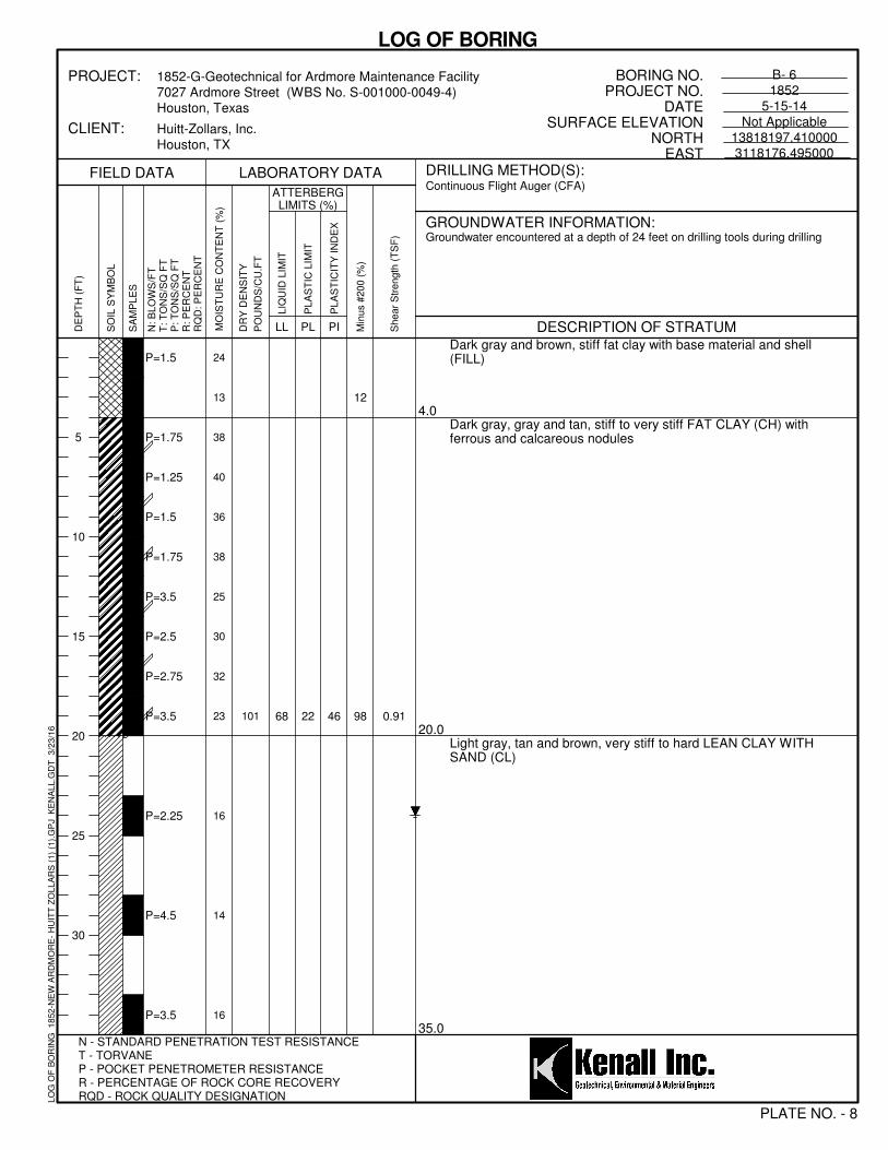
22 46
12
98 0.91
24
13
38
40
36
38
25
30
32
23
16
14
16
P=1.5
P=1.75
P=1.25
P=1.5
P=1.75
P=3.5
P=2.5
P=2.75
P=3.5
P=2.25
P=4.5
P=3.5
101 68
Dark gray and brown, stiff fat clay with base material and shell(FILL)
Dark gray, gray and tan, stiff to very stiff FAT CLAY (CH) withferrous and calcareous nodules
Light gray, tan and brown, very stiff to hard LEAN CLAY WITHSAND (CL)
4.0
20.0
35.0
Min
us #
200 (
%)
ATTERBERGLIMITS (%)
N - STANDARD PENETRATION TEST RESISTANCET - TORVANEP - POCKET PENETROMETER RESISTANCER - PERCENTAGE OF ROCK CORE RECOVERYRQD - ROCK QUALITY DESIGNATION
5
10
15
20
25
30
Shear
Str
ength
(T
SF
)
LABORATORY DATA
PLATE NO. - 8
DRILLING METHOD(S):
PL PI
BORING NO.PROJECT NO.
DATESURFACE ELEVATION
NORTHEAST
GROUNDWATER INFORMATION:
B- 61852
5-15-14Not Applicable
13818197.4100003118176.495000
DR
Y D
EN
SIT
Y
PO
UN
DS
/CU
.FT
SO
IL S
YM
BO
L
CLIENT:
PROJECT:
DESCRIPTION OF STRATUM
Groundwater encountered at a depth of 24 feet on drilling tools during drilling
N: B
LO
WS
/FT
T: T
ON
S/S
Q F
TP
: T
ON
S/S
Q F
TR
: P
ER
CE
NT
RQ
D: P
ER
CE
NT
LIQ
UID
LIM
IT
1852-G-Geotechnical for Ardmore Maintenance Facility7027 Ardmore Street (WBS No. S-001000-0049-4)Houston, Texas
Huitt-Zollars, Inc.Houston, TX
FIELD DATA
SA
MP
LE
S
MO
IST
UR
E C
ON
TE
NT
(%
)
Continuous Flight Auger (CFA)
LL
LOG OF BORING
PLA
ST
IC L
IMIT
PLA
ST
ICIT
Y IN
DE
X
DE
PT
H (
FT
)
LO
G O
F B
OR
ING
1
85
2-N
EW
AR
DM
OR
E-
HU
ITT
ZO
LL
AR
S (
1)
(1).
GP
J
KE
NA
LL
.GD
T
3/2
3/1
6
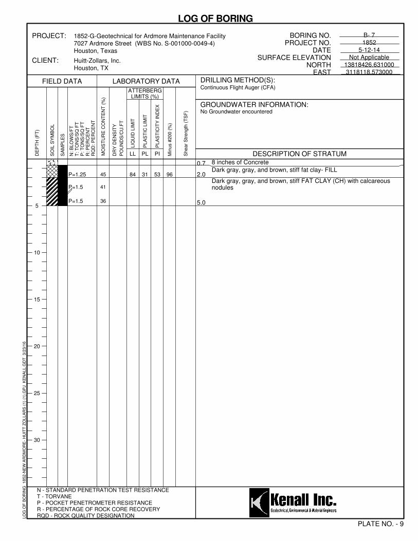
31 53 9645
41
36
P=1.25
P=1.5
P=1.5
84
8 inches of Concrete
Dark gray, gray, and brown, stiff fat clay- FILL
Dark gray, gray, and brown, stiff FAT CLAY (CH) with calcareousnodules
0.7
2.0
5.0
Min
us #
200 (
%)
ATTERBERGLIMITS (%)
N - STANDARD PENETRATION TEST RESISTANCET - TORVANEP - POCKET PENETROMETER RESISTANCER - PERCENTAGE OF ROCK CORE RECOVERYRQD - ROCK QUALITY DESIGNATION
5
10
15
20
25
30
Shear
Str
ength
(T
SF
)
LABORATORY DATA
PLATE NO. - 9
DRILLING METHOD(S):
PL PI
BORING NO.PROJECT NO.
DATESURFACE ELEVATION
NORTHEAST
GROUNDWATER INFORMATION:
B- 71852
5-12-14Not Applicable
13818426.6310003118118.573000
DR
Y D
EN
SIT
Y
PO
UN
DS
/CU
.FT
SO
IL S
YM
BO
L
CLIENT:
PROJECT:
DESCRIPTION OF STRATUM
No Groundwater encountered
N: B
LO
WS
/FT
T: T
ON
S/S
Q F
TP
: T
ON
S/S
Q F
TR
: P
ER
CE
NT
RQ
D: P
ER
CE
NT
LIQ
UID
LIM
IT
1852-G-Geotechnical for Ardmore Maintenance Facility7027 Ardmore Street (WBS No. S-001000-0049-4)Houston, Texas
Huitt-Zollars, Inc.Houston, TX
FIELD DATA
SA
MP
LE
S
MO
IST
UR
E C
ON
TE
NT
(%
)
Continuous Flight Auger (CFA)
LL
LOG OF BORING
PLA
ST
IC L
IMIT
PLA
ST
ICIT
Y IN
DE
X
DE
PT
H (
FT
)
LO
G O
F B
OR
ING
1
85
2-N
EW
AR
DM
OR
E-
HU
ITT
ZO
LL
AR
S (
1)
(1).
GP
J
KE
NA
LL
.GD
T
3/2
3/1
6

28 71 94
44
45
41
P=4.5
P=1.0
P=1.25
99
8 inches of Concrete
Dark gray, gray, and brown, hard fat clay- FILL
Dark gray, gray, and brown, stiff FAT CLAY (CH) with calcareousnodules
0.7
2.0
5.0
Min
us #
200 (
%)
ATTERBERGLIMITS (%)
N - STANDARD PENETRATION TEST RESISTANCET - TORVANEP - POCKET PENETROMETER RESISTANCER - PERCENTAGE OF ROCK CORE RECOVERYRQD - ROCK QUALITY DESIGNATION
5
10
15
20
25
30
Shear
Str
ength
(T
SF
)
LABORATORY DATA
PLATE NO. - 10
DRILLING METHOD(S):
PL PI
BORING NO.PROJECT NO.
DATESURFACE ELEVATION
NORTHEAST
GROUNDWATER INFORMATION:
B- 81852
5-12-14Not Applicable
13818767.3670003118184.249000
DR
Y D
EN
SIT
Y
PO
UN
DS
/CU
.FT
SO
IL S
YM
BO
L
CLIENT:
PROJECT:
DESCRIPTION OF STRATUM
No Groundwater encountered
N: B
LO
WS
/FT
T: T
ON
S/S
Q F
TP
: T
ON
S/S
Q F
TR
: P
ER
CE
NT
RQ
D: P
ER
CE
NT
LIQ
UID
LIM
IT
1852-G-Geotechnical for Ardmore Maintenance Facility7027 Ardmore Street (WBS No. S-001000-0049-4)Houston, Texas
Huitt-Zollars, Inc.Houston, TX
FIELD DATA
SA
MP
LE
S
MO
IST
UR
E C
ON
TE
NT
(%
)
Continuous Flight Auger (CFA)
LL
LOG OF BORING
PLA
ST
IC L
IMIT
PLA
ST
ICIT
Y IN
DE
X
DE
PT
H (
FT
)
LO
G O
F B
OR
ING
1
85
2-N
EW
AR
DM
OR
E-
HU
ITT
ZO
LL
AR
S (
1)
(1).
GP
J
KE
NA
LL
.GD
T
3/2
3/1
6

27 56 96
45
37
36
P=1.5
P=1.5
P=1.5 83
9 inches of Concrete
Dark gray, gray, and brown, stiff fat clay- FILL
Dark gray, and gray, stiff FAT CLAY (CH) with calcareous nodules
0.8
2.0
5.0
Min
us #
200 (
%)
ATTERBERGLIMITS (%)
N - STANDARD PENETRATION TEST RESISTANCET - TORVANEP - POCKET PENETROMETER RESISTANCER - PERCENTAGE OF ROCK CORE RECOVERYRQD - ROCK QUALITY DESIGNATION
5
10
15
20
25
30
Shear
Str
ength
(T
SF
)
LABORATORY DATA
PLATE NO. - 11
DRILLING METHOD(S):
PL PI
BORING NO.PROJECT NO.
DATESURFACE ELEVATION
NORTHEAST
GROUNDWATER INFORMATION:
B- 91852
5-12-14Not Applicable
13818369.9360003118284.862000
DR
Y D
EN
SIT
Y
PO
UN
DS
/CU
.FT
SO
IL S
YM
BO
L
CLIENT:
PROJECT:
DESCRIPTION OF STRATUM
No Groundwater encountered
N: B
LO
WS
/FT
T: T
ON
S/S
Q F
TP
: T
ON
S/S
Q F
TR
: P
ER
CE
NT
RQ
D: P
ER
CE
NT
LIQ
UID
LIM
IT
1852-G-Geotechnical for Ardmore Maintenance Facility7027 Ardmore Street (WBS No. S-001000-0049-4)Houston, Texas
Huitt-Zollars, Inc.Houston, TX
FIELD DATA
SA
MP
LE
S
MO
IST
UR
E C
ON
TE
NT
(%
)
Continuous Flight Auger (CFA)
LL
LOG OF BORING
PLA
ST
IC L
IMIT
PLA
ST
ICIT
Y IN
DE
X
DE
PT
H (
FT
)
LO
G O
F B
OR
ING
1
85
2-N
EW
AR
DM
OR
E-
HU
ITT
ZO
LL
AR
S (
1)
(1).
GP
J
KE
NA
LL
.GD
T
3/2
3/1
6

20 35 6319
31
30
P=1.5
P=3.5
P=3.0
55Dark gray, gray and brown, stiff fat clay- FILL
Dark gray, and gray, very stiff FAT CLAY (CH) with calcareousnodules
2.0
5.0
Min
us #
200 (
%)
ATTERBERGLIMITS (%)
N - STANDARD PENETRATION TEST RESISTANCET - TORVANEP - POCKET PENETROMETER RESISTANCER - PERCENTAGE OF ROCK CORE RECOVERYRQD - ROCK QUALITY DESIGNATION
5
10
15
20
25
30
Shear
Str
ength
(T
SF
)
LABORATORY DATA
PLATE NO. - 12
DRILLING METHOD(S):
PL PI
BORING NO.PROJECT NO.
DATESURFACE ELEVATION
NORTHEAST
GROUNDWATER INFORMATION:
B-101852
5-14-14Not Applicable
13818328.9400003118088.884000
DR
Y D
EN
SIT
Y
PO
UN
DS
/CU
.FT
SO
IL S
YM
BO
L
CLIENT:
PROJECT:
DESCRIPTION OF STRATUM
No Groundwater encountered
N: B
LO
WS
/FT
T: T
ON
S/S
Q F
TP
: T
ON
S/S
Q F
TR
: P
ER
CE
NT
RQ
D: P
ER
CE
NT
LIQ
UID
LIM
IT
1852-G-Geotechnical for Ardmore Maintenance Facility7027 Ardmore Street (WBS No. S-001000-0049-4)Houston, Texas
Huitt-Zollars, Inc.Houston, TX
FIELD DATA
SA
MP
LE
S
MO
IST
UR
E C
ON
TE
NT
(%
)
Continuous Flight Auger (CFA)
LL
LOG OF BORING
PLA
ST
IC L
IMIT
PLA
ST
ICIT
Y IN
DE
X
DE
PT
H (
FT
)
LO
G O
F B
OR
ING
1
85
2-N
EW
AR
DM
OR
E-
HU
ITT
ZO
LL
AR
S (
1)
(1).
GP
J
KE
NA
LL
.GD
T
3/2
3/1
6

25 63 96
35
37
36
P=1.25
P=1.5
P=2.0
88
Dark gray, stiff fat clay- FILL
Dark gray, and gray, stiff FAT CLAY (CH) with calcareous nodules2.0
5.0
Min
us #
200 (
%)
ATTERBERGLIMITS (%)
N - STANDARD PENETRATION TEST RESISTANCET - TORVANEP - POCKET PENETROMETER RESISTANCER - PERCENTAGE OF ROCK CORE RECOVERYRQD - ROCK QUALITY DESIGNATION
5
10
15
20
25
30
Shear
Str
ength
(T
SF
)
LABORATORY DATA
PLATE NO. - 13
DRILLING METHOD(S):
PL PI
BORING NO.PROJECT NO.
DATESURFACE ELEVATION
NORTHEAST
GROUNDWATER INFORMATION:
B-111852
5-14-14Not Applicable
13818275.8290003118194.712000
DR
Y D
EN
SIT
Y
PO
UN
DS
/CU
.FT
SO
IL S
YM
BO
L
CLIENT:
PROJECT:
DESCRIPTION OF STRATUM
No Groundwater encountered
N: B
LO
WS
/FT
T: T
ON
S/S
Q F
TP
: T
ON
S/S
Q F
TR
: P
ER
CE
NT
RQ
D: P
ER
CE
NT
LIQ
UID
LIM
IT
1852-G-Geotechnical for Ardmore Maintenance Facility7027 Ardmore Street (WBS No. S-001000-0049-4)Houston, Texas
Huitt-Zollars, Inc.Houston, TX
FIELD DATA
SA
MP
LE
S
MO
IST
UR
E C
ON
TE
NT
(%
)
Continuous Flight Auger (CFA)
LL
LOG OF BORING
PLA
ST
IC L
IMIT
PLA
ST
ICIT
Y IN
DE
X
DE
PT
H (
FT
)
LO
G O
F B
OR
ING
1
85
2-N
EW
AR
DM
OR
E-
HU
ITT
ZO
LL
AR
S (
1)
(1).
GP
J
KE
NA
LL
.GD
T
3/2
3/1
6

22 51 7721
31
33
P=2.25
P=3.5
P=3.0
73Dark gray, very stiff fat clay- FILL
Dark gray, and gray, very stiff FAT CLAY WITH SAND (CH) withcalcareous nodules
2.0
5.0
Min
us #
200 (
%)
ATTERBERGLIMITS (%)
N - STANDARD PENETRATION TEST RESISTANCET - TORVANEP - POCKET PENETROMETER RESISTANCER - PERCENTAGE OF ROCK CORE RECOVERYRQD - ROCK QUALITY DESIGNATION
5
10
15
20
25
30
Shear
Str
ength
(T
SF
)
LABORATORY DATA
PLATE NO. - 14
DRILLING METHOD(S):
PL PI
BORING NO.PROJECT NO.
DATESURFACE ELEVATION
NORTHEAST
GROUNDWATER INFORMATION:
B-121852
5-14-14Not Applicable
13818164.1670003118054.601000
DR
Y D
EN
SIT
Y
PO
UN
DS
/CU
.FT
SO
IL S
YM
BO
L
CLIENT:
PROJECT:
DESCRIPTION OF STRATUM
No Groundwater encountered
N: B
LO
WS
/FT
T: T
ON
S/S
Q F
TP
: T
ON
S/S
Q F
TR
: P
ER
CE
NT
RQ
D: P
ER
CE
NT
LIQ
UID
LIM
IT
1852-G-Geotechnical for Ardmore Maintenance Facility7027 Ardmore Street (WBS No. S-001000-0049-4)Houston, Texas
Huitt-Zollars, Inc.Houston, TX
FIELD DATA
SA
MP
LE
S
MO
IST
UR
E C
ON
TE
NT
(%
)
Continuous Flight Auger (CFA)
LL
LOG OF BORING
PLA
ST
IC L
IMIT
PLA
ST
ICIT
Y IN
DE
X
DE
PT
H (
FT
)
LO
G O
F B
OR
ING
1
85
2-N
EW
AR
DM
OR
E-
HU
ITT
ZO
LL
AR
S (
1)
(1).
GP
J
KE
NA
LL
.GD
T
3/2
3/1
6

23
22
27
P=2.5
P=4.5
Dark gray and brown, very stiff fat clay with base material
Dark gray and brown, hard FAT CLAY4.0
5.0
Min
us #
200 (
%)
ATTERBERGLIMITS (%)
N - STANDARD PENETRATION TEST RESISTANCET - TORVANEP - POCKET PENETROMETER RESISTANCER - PERCENTAGE OF ROCK CORE RECOVERYRQD - ROCK QUALITY DESIGNATION
5
10
15
20
25
30
Shear
Str
ength
(T
SF
)
LABORATORY DATA
PLATE NO. - 15
DRILLING METHOD(S):
PL PI
BORING NO.PROJECT NO.
DATESURFACE ELEVATION
NORTHEAST
GROUNDWATER INFORMATION:
B-131852
5-14-14Not Applicable
13818152.9300003118102.912000
DR
Y D
EN
SIT
Y
PO
UN
DS
/CU
.FT
SO
IL S
YM
BO
L
CLIENT:
PROJECT:
DESCRIPTION OF STRATUM
No Groundwater encountered
N: B
LO
WS
/FT
T: T
ON
S/S
Q F
TP
: T
ON
S/S
Q F
TR
: P
ER
CE
NT
RQ
D: P
ER
CE
NT
LIQ
UID
LIM
IT
1852-G-Geotechnical for Ardmore Maintenance Facility7027 Ardmore Street (WBS No. S-001000-0049-4)Houston, Texas
Huitt-Zollars, Inc.Houston, TX
FIELD DATA
SA
MP
LE
S
MO
IST
UR
E C
ON
TE
NT
(%
)
Continuous Flight Auger (CFA)
LL
LOG OF BORING
PLA
ST
IC L
IMIT
PLA
ST
ICIT
Y IN
DE
X
DE
PT
H (
FT
)
LO
G O
F B
OR
ING
1
85
2-N
EW
AR
DM
OR
E-
HU
ITT
ZO
LL
AR
S (
1)
(1).
GP
J
KE
NA
LL
.GD
T
3/2
3/1
6

25
24
67
49
92
93 0.74
37
38
21
30
27
29
30
33
25
26
P=1.75
P=1.75
P=4.5
P=4.5
P=4.5
P=3.75
P=3.5
P=2.75
P=3.75
P=3.75
92
92
73
Dark gray and brown, stiff fat clay- FILL
Dark gray, gray and tan, stiff to hard FAT CLAY (CH) with ferroudand calcareous nodules
2.0
20.0
Min
us #
200 (
%)
ATTERBERGLIMITS (%)
N - STANDARD PENETRATION TEST RESISTANCET - TORVANEP - POCKET PENETROMETER RESISTANCER - PERCENTAGE OF ROCK CORE RECOVERYRQD - ROCK QUALITY DESIGNATION
5
10
15
20
25
30
Shear
Str
ength
(T
SF
)
LABORATORY DATA
PLATE NO. - 16
DRILLING METHOD(S):
PL PI
BORING NO.PROJECT NO.
DATESURFACE ELEVATION
NORTHEAST
GROUNDWATER INFORMATION:
B-141852
5-14-14Not Applicable
13818263.6640003118400.914000
DR
Y D
EN
SIT
Y
PO
UN
DS
/CU
.FT
SO
IL S
YM
BO
L
CLIENT:
PROJECT:
DESCRIPTION OF STRATUM
No Groundwater encountered
N: B
LO
WS
/FT
T: T
ON
S/S
Q F
TP
: T
ON
S/S
Q F
TR
: P
ER
CE
NT
RQ
D: P
ER
CE
NT
LIQ
UID
LIM
IT
1852-G-Geotechnical for Ardmore Maintenance Facility7027 Ardmore Street (WBS No. S-001000-0049-4)Houston, Texas
Huitt-Zollars, Inc.Houston, TX
FIELD DATA
SA
MP
LE
S
MO
IST
UR
E C
ON
TE
NT
(%
)
Continuous Flight Auger (CFA)
LL
LOG OF BORING
PLA
ST
IC L
IMIT
PLA
ST
ICIT
Y IN
DE
X
DE
PT
H (
FT
)
LO
G O
F B
OR
ING
1
85
2-N
EW
AR
DM
OR
E-
HU
ITT
ZO
LL
AR
S (
1)
(1).
GP
J
KE
NA
LL
.GD
T
3/2
3/1
6
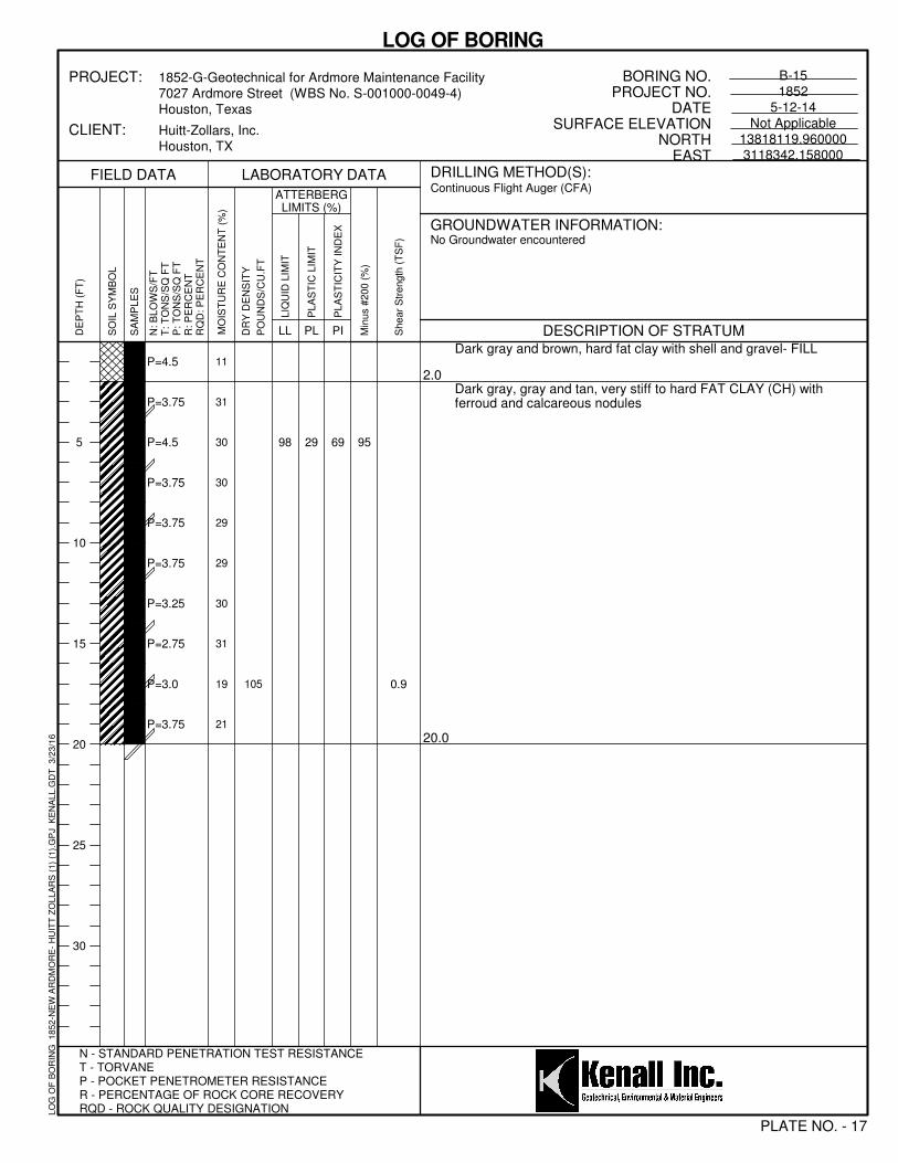
29 69 95
0.9
11
31
30
30
29
29
30
31
19
21
P=4.5
P=3.75
P=4.5
P=3.75
P=3.75
P=3.75
P=3.25
P=2.75
P=3.0
P=3.75
105
98
Dark gray and brown, hard fat clay with shell and gravel- FILL
Dark gray, gray and tan, very stiff to hard FAT CLAY (CH) withferroud and calcareous nodules
2.0
20.0
Min
us #
200 (
%)
ATTERBERGLIMITS (%)
N - STANDARD PENETRATION TEST RESISTANCET - TORVANEP - POCKET PENETROMETER RESISTANCER - PERCENTAGE OF ROCK CORE RECOVERYRQD - ROCK QUALITY DESIGNATION
5
10
15
20
25
30
Shear
Str
ength
(T
SF
)
LABORATORY DATA
PLATE NO. - 17
DRILLING METHOD(S):
PL PI
BORING NO.PROJECT NO.
DATESURFACE ELEVATION
NORTHEAST
GROUNDWATER INFORMATION:
B-151852
5-12-14Not Applicable
13818119.9600003118342.158000
DR
Y D
EN
SIT
Y
PO
UN
DS
/CU
.FT
SO
IL S
YM
BO
L
CLIENT:
PROJECT:
DESCRIPTION OF STRATUM
No Groundwater encountered
N: B
LO
WS
/FT
T: T
ON
S/S
Q F
TP
: T
ON
S/S
Q F
TR
: P
ER
CE
NT
RQ
D: P
ER
CE
NT
LIQ
UID
LIM
IT
1852-G-Geotechnical for Ardmore Maintenance Facility7027 Ardmore Street (WBS No. S-001000-0049-4)Houston, Texas
Huitt-Zollars, Inc.Houston, TX
FIELD DATA
SA
MP
LE
S
MO
IST
UR
E C
ON
TE
NT
(%
)
Continuous Flight Auger (CFA)
LL
LOG OF BORING
PLA
ST
IC L
IMIT
PLA
ST
ICIT
Y IN
DE
X
DE
PT
H (
FT
)
LO
G O
F B
OR
ING
1
85
2-N
EW
AR
DM
OR
E-
HU
ITT
ZO
LL
AR
S (
1)
(1).
GP
J
KE
NA
LL
.GD
T
3/2
3/1
6

29
23
60
46
96
96 0.63
29
19
34
31
33
32
32
36
22
24
P=1.5
P=2.75
P=3.5
P=3.75
P=3.75
P=2.25
P=3.0
P=2.5
P=4.5
P=3.75
91
89
69
Dark gray and brown, stiff to hard fat clay with shell and gravel-FILL
Dark gray, gray and tan, very stiff to hard FAT CLAY (CH) withferrous and calcareous nodules
4.0
20.0
Min
us #
200 (
%)
ATTERBERGLIMITS (%)
N - STANDARD PENETRATION TEST RESISTANCET - TORVANEP - POCKET PENETROMETER RESISTANCER - PERCENTAGE OF ROCK CORE RECOVERYRQD - ROCK QUALITY DESIGNATION
5
10
15
20
25
30
Shear
Str
ength
(T
SF
)
LABORATORY DATA
PLATE NO. - 18
DRILLING METHOD(S):
PL PI
BORING NO.PROJECT NO.
DATESURFACE ELEVATION
NORTHEAST
GROUNDWATER INFORMATION:
B-161852
5-14-14Not Applicable
13818007.3610003118077.881000
DR
Y D
EN
SIT
Y
PO
UN
DS
/CU
.FT
SO
IL S
YM
BO
L
CLIENT:
PROJECT:
DESCRIPTION OF STRATUM
No Groundwater encountered
N: B
LO
WS
/FT
T: T
ON
S/S
Q F
TP
: T
ON
S/S
Q F
TR
: P
ER
CE
NT
RQ
D: P
ER
CE
NT
LIQ
UID
LIM
IT
1852-G-Geotechnical for Ardmore Maintenance Facility7027 Ardmore Street (WBS No. S-001000-0049-4)Houston, Texas
Huitt-Zollars, Inc.Houston, TX
FIELD DATA
SA
MP
LE
S
MO
IST
UR
E C
ON
TE
NT
(%
)
Continuous Flight Auger (CFA)
LL
LOG OF BORING
PLA
ST
IC L
IMIT
PLA
ST
ICIT
Y IN
DE
X
DE
PT
H (
FT
)
LO
G O
F B
OR
ING
1
85
2-N
EW
AR
DM
OR
E-
HU
ITT
ZO
LL
AR
S (
1)
(1).
GP
J
KE
NA
LL
.GD
T
3/2
3/1
6

26
21
74
47
97
96 0.49
32
40
23
30
30
27
31
20
34
24
P=3.5
P=1.75
P=2.5
P=3.0
P=1.75
P=2.5
P=2.5
P=2.25
P=1.75
P=1.25
96
100
68
Dark gray, gray and brown, very stiff fat clay with shells- FILL
Dark gray, light gray, reddish brown and tan, stiff to very stiff FATCLAY (CH) with ferrous and calcareous nodules
2.0
20.0
Min
us #
200 (
%)
ATTERBERGLIMITS (%)
N - STANDARD PENETRATION TEST RESISTANCET - TORVANEP - POCKET PENETROMETER RESISTANCER - PERCENTAGE OF ROCK CORE RECOVERYRQD - ROCK QUALITY DESIGNATION
5
10
15
20
25
30
Shear
Str
ength
(T
SF
)
LABORATORY DATA
PLATE NO. - 19
DRILLING METHOD(S):
PL PI
BORING NO.PROJECT NO.
DATESURFACE ELEVATION
NORTHEAST
GROUNDWATER INFORMATION:
B-171852
8-27-14Not Applicable
13818347.4370003118087.040000
DR
Y D
EN
SIT
Y
PO
UN
DS
/CU
.FT
SO
IL S
YM
BO
L
CLIENT:
PROJECT:
DESCRIPTION OF STRATUM
No Groundwater encountered
N: B
LO
WS
/FT
T: T
ON
S/S
Q F
TP
: T
ON
S/S
Q F
TR
: P
ER
CE
NT
RQ
D: P
ER
CE
NT
LIQ
UID
LIM
IT
1852-G-Geotechnical for Ardmore Maintenance Facility7027 Ardmore Street (WBS No. S-001000-0049-4)Houston, Texas
Huitt-Zollars, Inc.Houston, TX
FIELD DATA
SA
MP
LE
S
MO
IST
UR
E C
ON
TE
NT
(%
)
Continuous Flight Auger (CFA)
LL
LOG OF BORING
PLA
ST
IC L
IMIT
PLA
ST
ICIT
Y IN
DE
X
DE
PT
H (
FT
)
LO
G O
F B
OR
ING
1
85
2-N
EW
AR
DM
OR
E-
HU
ITT
ZO
LL
AR
S (
1)
(1).
GP
J
KE
NA
LL
.GD
T
3/2
3/1
6

25
24
72
65
96
99 0.77
32
40
23
30
30
27
31
20
34
24
P=4.5
P=3.5
P=2.0
P=3.0
P=3.0
P=2.25
P=3.0
P=2.75
P=2.5
P=3.0
97
97
89
Dark gray, gray and brown, hard fat clay with shells- FILL
Dark gray, light gray, reddish brown and tan, very stiff FAT CLAY(CH) with ferrous and calcareous nodules
2.0
20.0
Min
us #
200 (
%)
ATTERBERGLIMITS (%)
N - STANDARD PENETRATION TEST RESISTANCET - TORVANEP - POCKET PENETROMETER RESISTANCER - PERCENTAGE OF ROCK CORE RECOVERYRQD - ROCK QUALITY DESIGNATION
5
10
15
20
25
30
Shear
Str
ength
(T
SF
)
LABORATORY DATA
PLATE NO. - 20
DRILLING METHOD(S):
PL PI
BORING NO.PROJECT NO.
DATESURFACE ELEVATION
NORTHEAST
GROUNDWATER INFORMATION:
B-181852
8-27-14Not Applicable
13818367.6730003118106.106000
DR
Y D
EN
SIT
Y
PO
UN
DS
/CU
.FT
SO
IL S
YM
BO
L
CLIENT:
PROJECT:
DESCRIPTION OF STRATUM
No Groundwater encountered
N: B
LO
WS
/FT
T: T
ON
S/S
Q F
TP
: T
ON
S/S
Q F
TR
: P
ER
CE
NT
RQ
D: P
ER
CE
NT
LIQ
UID
LIM
IT
1852-G-Geotechnical for Ardmore Maintenance Facility7027 Ardmore Street (WBS No. S-001000-0049-4)Houston, Texas
Huitt-Zollars, Inc.Houston, TX
FIELD DATA
SA
MP
LE
S
MO
IST
UR
E C
ON
TE
NT
(%
)
Continuous Flight Auger (CFA)
LL
LOG OF BORING
PLA
ST
IC L
IMIT
PLA
ST
ICIT
Y IN
DE
X
DE
PT
H (
FT
)
LO
G O
F B
OR
ING
1
85
2-N
EW
AR
DM
OR
E-
HU
ITT
ZO
LL
AR
S (
1)
(1).
GP
J
KE
NA
LL
.GD
T
3/2
3/1
6

22
25
51
68
83
96 0.55
22
33
40
35
29
37
31
32
34
29
P=4.5
P=3.5
P=1.5
P=3.0
P=2.75
P=2.75
P=3.0
P=3.0
P=2.75
P=3.0 95
73
93
Dark gray, gray and brown, very stiff to hard fat clay with sand withshells- FILL
Dark gray, light gray, reddish brown and tan, stiff to very stiff FATCLAY (CH) with ferrous and calcareous nodules
4.0
20.0
Min
us #
200 (
%)
ATTERBERGLIMITS (%)
N - STANDARD PENETRATION TEST RESISTANCET - TORVANEP - POCKET PENETROMETER RESISTANCER - PERCENTAGE OF ROCK CORE RECOVERYRQD - ROCK QUALITY DESIGNATION
5
10
15
20
25
30
Shear
Str
ength
(T
SF
)
LABORATORY DATA
PLATE NO. - 21
DRILLING METHOD(S):
PL PI
BORING NO.PROJECT NO.
DATESURFACE ELEVATION
NORTHEAST
GROUNDWATER INFORMATION:
B-191852
8-27-14Not Applicable
13818206.3470003118042.177000
DR
Y D
EN
SIT
Y
PO
UN
DS
/CU
.FT
SO
IL S
YM
BO
L
CLIENT:
PROJECT:
DESCRIPTION OF STRATUM
No Groundwater encountered
N: B
LO
WS
/FT
T: T
ON
S/S
Q F
TP
: T
ON
S/S
Q F
TR
: P
ER
CE
NT
RQ
D: P
ER
CE
NT
LIQ
UID
LIM
IT
1852-G-Geotechnical for Ardmore Maintenance Facility7027 Ardmore Street (WBS No. S-001000-0049-4)Houston, Texas
Huitt-Zollars, Inc.Houston, TX
FIELD DATA
SA
MP
LE
S
MO
IST
UR
E C
ON
TE
NT
(%
)
Continuous Flight Auger (CFA)
LL
LOG OF BORING
PLA
ST
IC L
IMIT
PLA
ST
ICIT
Y IN
DE
X
DE
PT
H (
FT
)
LO
G O
F B
OR
ING
1
85
2-N
EW
AR
DM
OR
E-
HU
ITT
ZO
LL
AR
S (
1)
(1).
GP
J
KE
NA
LL
.GD
T
3/2
3/1
6

26
23
66
57
96
97 0.52
25
21
28
42
36
38
38
40
32
30
17
17
P=2.5
P=1.5
P=2.25
P=1.25
P=1.75
P=1.25
P=1.5
P=1.5
P=2.5
P=2.75
P=2.75
P=2.75
87
92
80
Dark gray, gray and brown, stiff to very stiff fat clay with shells- FILL
Dark gray, light gray, reddish brown and tan, stiff to very stiff FATCLAY (CH) with ferrous and calcareous nodules
Light gray, brown and tan, very stiff LEAN CLAY WITH SAND (CL)with ferrous and calcareous nodules
4.0
23.0
30.0
Min
us #
200 (
%)
ATTERBERGLIMITS (%)
N - STANDARD PENETRATION TEST RESISTANCET - TORVANEP - POCKET PENETROMETER RESISTANCER - PERCENTAGE OF ROCK CORE RECOVERYRQD - ROCK QUALITY DESIGNATION
5
10
15
20
25
30
Shear
Str
ength
(T
SF
)
LABORATORY DATA
PLATE NO. - 22
DRILLING METHOD(S):
PL PI
BORING NO.PROJECT NO.
DATESURFACE ELEVATION
NORTHEAST
GROUNDWATER INFORMATION:
B-201852
8-27-14Not Applicable
13818197.3100003118067.550000
DR
Y D
EN
SIT
Y
PO
UN
DS
/CU
.FT
SO
IL S
YM
BO
L
CLIENT:
PROJECT:
DESCRIPTION OF STRATUM
No Groundwater encountered
N: B
LO
WS
/FT
T: T
ON
S/S
Q F
TP
: T
ON
S/S
Q F
TR
: P
ER
CE
NT
RQ
D: P
ER
CE
NT
LIQ
UID
LIM
IT
1852-G-Geotechnical for Ardmore Maintenance Facility7027 Ardmore Street (WBS No. S-001000-0049-4)Houston, Texas
Huitt-Zollars, Inc.Houston, TX
FIELD DATA
SA
MP
LE
S
MO
IST
UR
E C
ON
TE
NT
(%
)
Continuous Flight Auger (CFA)
LL
LOG OF BORING
PLA
ST
IC L
IMIT
PLA
ST
ICIT
Y IN
DE
X
DE
PT
H (
FT
)
LO
G O
F B
OR
ING
1
85
2-N
EW
AR
DM
OR
E-
HU
ITT
ZO
LL
AR
S (
1)
(1).
GP
J
KE
NA
LL
.GD
T
3/2
3/1
6
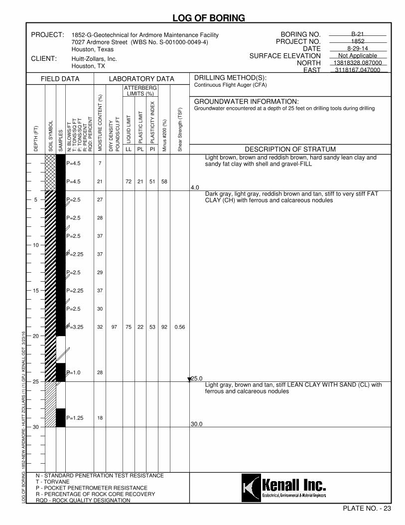
21
22
51
53
58
92 0.56
7
21
27
28
37
37
29
37
30
32
28
18
P=4.5
P=4.5
P=2.5
P=2.5
P=2.5
P=2.25
P=2.5
P=2.25
P=2.5
P=3.25
P=1.0
P=1.25
97
72
75
Light brown, brown and reddish brown, hard sandy lean clay andsandy fat clay with shell and gravel-FILL
Dark gray, light gray, reddish brown and tan, stiff to very stiff FATCLAY (CH) with ferrous and calcareous nodules
Light gray, brown and tan, stiff LEAN CLAY WITH SAND (CL) withferrous and calcareous nodules
4.0
25.0
30.0
Min
us #
200 (
%)
ATTERBERGLIMITS (%)
N - STANDARD PENETRATION TEST RESISTANCET - TORVANEP - POCKET PENETROMETER RESISTANCER - PERCENTAGE OF ROCK CORE RECOVERYRQD - ROCK QUALITY DESIGNATION
5
10
15
20
25
30
Shear
Str
ength
(T
SF
)
LABORATORY DATA
PLATE NO. - 23
DRILLING METHOD(S):
PL PI
BORING NO.PROJECT NO.
DATESURFACE ELEVATION
NORTHEAST
GROUNDWATER INFORMATION:
B-211852
8-29-14Not Applicable
13818328.0870003118167.047000
DR
Y D
EN
SIT
Y
PO
UN
DS
/CU
.FT
SO
IL S
YM
BO
L
CLIENT:
PROJECT:
DESCRIPTION OF STRATUM
Groundwater encountered at a depth of 25 feet on drilling tools during drilling
N: B
LO
WS
/FT
T: T
ON
S/S
Q F
TP
: T
ON
S/S
Q F
TR
: P
ER
CE
NT
RQ
D: P
ER
CE
NT
LIQ
UID
LIM
IT
1852-G-Geotechnical for Ardmore Maintenance Facility7027 Ardmore Street (WBS No. S-001000-0049-4)Houston, Texas
Huitt-Zollars, Inc.Houston, TX
FIELD DATA
SA
MP
LE
S
MO
IST
UR
E C
ON
TE
NT
(%
)
Continuous Flight Auger (CFA)
LL
LOG OF BORING
PLA
ST
IC L
IMIT
PLA
ST
ICIT
Y IN
DE
X
DE
PT
H (
FT
)
LO
G O
F B
OR
ING
1
85
2-N
EW
AR
DM
OR
E-
HU
ITT
ZO
LL
AR
S (
1)
(1).
GP
J
KE
NA
LL
.GD
T
3/2
3/1
6

22
22
60
45
92
100 0.98
21
29
33
31
34
36
36
38
32
31
24
19
P=4.5
P=3.75
P=2.5
P=1.5
P=2.25
P=1.5
P=1.25
P=1.75
P=2.75
P=2.25
P=2.75
P=1.0
106
82
67
Light brown, brown and reddish brown, very stiff to hard sandy leanclay and fat clay with shell and gravel-FILL
Dark gray, light gray, reddish brown and tan, stiff to very stiff FATCLAY (CH) with ferrous and calcareous nodules
Light gray, brown and tan, stiff LEAN CLAY WITH SAND (CL) withferrous and calcareous nodules
4.0
25.0
30.0
Min
us #
200 (
%)
ATTERBERGLIMITS (%)
N - STANDARD PENETRATION TEST RESISTANCET - TORVANEP - POCKET PENETROMETER RESISTANCER - PERCENTAGE OF ROCK CORE RECOVERYRQD - ROCK QUALITY DESIGNATION
5
10
15
20
25
30
Shear
Str
ength
(T
SF
)
LABORATORY DATA
PLATE NO. - 24
DRILLING METHOD(S):
PL PI
BORING NO.PROJECT NO.
DATESURFACE ELEVATION
NORTHEAST
GROUNDWATER INFORMATION:
B-221852
8-29-14Not Applicable
13818220.4450003118121.467000
DR
Y D
EN
SIT
Y
PO
UN
DS
/CU
.FT
SO
IL S
YM
BO
L
CLIENT:
PROJECT:
DESCRIPTION OF STRATUM
Groundwater encountered at a depth of 28 feet on drilling tools during drilling
N: B
LO
WS
/FT
T: T
ON
S/S
Q F
TP
: T
ON
S/S
Q F
TR
: P
ER
CE
NT
RQ
D: P
ER
CE
NT
LIQ
UID
LIM
IT
1852-G-Geotechnical for Ardmore Maintenance Facility7027 Ardmore Street (WBS No. S-001000-0049-4)Houston, Texas
Huitt-Zollars, Inc.Houston, TX
FIELD DATA
SA
MP
LE
S
MO
IST
UR
E C
ON
TE
NT
(%
)
Continuous Flight Auger (CFA)
LL
LOG OF BORING
PLA
ST
IC L
IMIT
PLA
ST
ICIT
Y IN
DE
X
DE
PT
H (
FT
)
LO
G O
F B
OR
ING
1
85
2-N
EW
AR
DM
OR
E-
HU
ITT
ZO
LL
AR
S (
1)
(1).
GP
J
KE
NA
LL
.GD
T
3/2
3/1
6

25
20
70
45
96
97 0.70
15
17
37
34
29
29
32
35
23
32
25
22
P=4.5
P=4.5
P=2.0
P=3.25
P=4.5
P=4.25
P=2.25
P=2.25
P=3.0
P=3.0
P=3.0
P=1.0
110
95
65
Light brown, brown and reddish brown, hard fat clay with shell andgravel-FILL
Dark gray, light gray, reddish brown and tan, stiff to hard FAT CLAY(CH) with ferrous and calcareous nodules
4.0
30.0
Min
us #
200 (
%)
ATTERBERGLIMITS (%)
N - STANDARD PENETRATION TEST RESISTANCET - TORVANEP - POCKET PENETROMETER RESISTANCER - PERCENTAGE OF ROCK CORE RECOVERYRQD - ROCK QUALITY DESIGNATION
5
10
15
20
25
30
Shear
Str
ength
(T
SF
)
LABORATORY DATA
PLATE NO. - 25
DRILLING METHOD(S):
PL PI
BORING NO.PROJECT NO.
DATESURFACE ELEVATION
NORTHEAST
GROUNDWATER INFORMATION:
B-231852
8-29-14Not Applicable
13818172.2230003118103.267000
DR
Y D
EN
SIT
Y
PO
UN
DS
/CU
.FT
SO
IL S
YM
BO
L
CLIENT:
PROJECT:
DESCRIPTION OF STRATUM
Groundwater encountered at a depth of 23 feet on drilling tools during drilling
N: B
LO
WS
/FT
T: T
ON
S/S
Q F
TP
: T
ON
S/S
Q F
TR
: P
ER
CE
NT
RQ
D: P
ER
CE
NT
LIQ
UID
LIM
IT
1852-G-Geotechnical for Ardmore Maintenance Facility7027 Ardmore Street (WBS No. S-001000-0049-4)Houston, Texas
Huitt-Zollars, Inc.Houston, TX
FIELD DATA
SA
MP
LE
S
MO
IST
UR
E C
ON
TE
NT
(%
)
Continuous Flight Auger (CFA)
LL
LOG OF BORING
PLA
ST
IC L
IMIT
PLA
ST
ICIT
Y IN
DE
X
DE
PT
H (
FT
)
LO
G O
F B
OR
ING
1
85
2-N
EW
AR
DM
OR
E-
HU
ITT
ZO
LL
AR
S (
1)
(1).
GP
J
KE
NA
LL
.GD
T
3/2
3/1
6

22
21
45
52
58
100 0.72
17
20
24
33
37
38
31
36
34
31
P=4.5
P=4.5
P=2.0
P=3.5
P=2.0
P=2.0
P=3.0
P=2.25
P=2.5
P=2.75
99
67
73
Light brown, brown and reddish brown, hard sandy fat clay withshell and gravel-FILL
Dark gray, light gray, reddish brown and tan, very stiff FAT CLAY(CH) with ferrous and calcareous nodules
4.0
20.0
Min
us #
200 (
%)
ATTERBERGLIMITS (%)
N - STANDARD PENETRATION TEST RESISTANCET - TORVANEP - POCKET PENETROMETER RESISTANCER - PERCENTAGE OF ROCK CORE RECOVERYRQD - ROCK QUALITY DESIGNATION
5
10
15
20
25
30
Shear
Str
ength
(T
SF
)
LABORATORY DATA
PLATE NO. - 26
DRILLING METHOD(S):
PL PI
BORING NO.PROJECT NO.
DATESURFACE ELEVATION
NORTHEAST
GROUNDWATER INFORMATION:
B-241852
8-29-14Not Applicable
13818201.3890003118163.984000
DR
Y D
EN
SIT
Y
PO
UN
DS
/CU
.FT
SO
IL S
YM
BO
L
CLIENT:
PROJECT:
DESCRIPTION OF STRATUM
No Groundwater encountered
N: B
LO
WS
/FT
T: T
ON
S/S
Q F
TP
: T
ON
S/S
Q F
TR
: P
ER
CE
NT
RQ
D: P
ER
CE
NT
LIQ
UID
LIM
IT
1852-G-Geotechnical for Ardmore Maintenance Facility7027 Ardmore Street (WBS No. S-001000-0049-4)Houston, Texas
Huitt-Zollars, Inc.Houston, TX
FIELD DATA
SA
MP
LE
S
MO
IST
UR
E C
ON
TE
NT
(%
)
Continuous Flight Auger (CFA)
LL
LOG OF BORING
PLA
ST
IC L
IMIT
PLA
ST
ICIT
Y IN
DE
X
DE
PT
H (
FT
)
LO
G O
F B
OR
ING
1
85
2-N
EW
AR
DM
OR
E-
HU
ITT
ZO
LL
AR
S (
1)
(1).
GP
J
KE
NA
LL
.GD
T
3/2
3/1
6

24
22
71
57
97
96
33
33
31
33
35
26
31
25
26
19
P=2.0
P=1.0
P=1.5
P=1.75
P=1.5
P=1.75
P=3.0
P=3.0
P=2.75
P=4.0
95
79
8 inches of concrete
Dark gray and brown, very stiff fat clay with shells and gravel-FILL
Dark brown, light gray and reddish brown, stiff to very stiff FATCLAY (CH) with ferrous and calcareous nodules
0.7
2.0
20.0
Min
us #
200 (
%)
ATTERBERGLIMITS (%)
N - STANDARD PENETRATION TEST RESISTANCET - TORVANEP - POCKET PENETROMETER RESISTANCER - PERCENTAGE OF ROCK CORE RECOVERYRQD - ROCK QUALITY DESIGNATION
5
10
15
20
25
30
Shear
Str
ength
(T
SF
)
LABORATORY DATA
PLATE NO. - 27
DRILLING METHOD(S):
PL PI
BORING NO.PROJECT NO.
DATESURFACE ELEVATION
NORTHEAST
GROUNDWATER INFORMATION:
B-251852
8-29-14Not Applicable
13817989.6760003118340.795000
DR
Y D
EN
SIT
Y
PO
UN
DS
/CU
.FT
SO
IL S
YM
BO
L
CLIENT:
PROJECT:
DESCRIPTION OF STRATUM
No Groundwater encountered
N: B
LO
WS
/FT
T: T
ON
S/S
Q F
TP
: T
ON
S/S
Q F
TR
: P
ER
CE
NT
RQ
D: P
ER
CE
NT
LIQ
UID
LIM
IT
1852-G-Geotechnical for Ardmore Maintenance Facility7027 Ardmore Street (WBS No. S-001000-0049-4)Houston, Texas
Huitt-Zollars, Inc.Houston, TX
FIELD DATA
SA
MP
LE
S
MO
IST
UR
E C
ON
TE
NT
(%
)
Continuous Flight Auger (CFA)
LL
LOG OF BORING
PLA
ST
IC L
IMIT
PLA
ST
ICIT
Y IN
DE
X
DE
PT
H (
FT
)
LO
G O
F B
OR
ING
1
85
2-N
EW
AR
DM
OR
E-
HU
ITT
ZO
LL
AR
S (
1)
(1).
GP
J
KE
NA
LL
.GD
T
3/2
3/1
6

Penetration Resistance Blow per Foot
0
0.25 to 0.50
Very Dense
30
40
50
0-15
15-35
35-65
65-85
No Recovery
0.50 to 1.00Loose
Dense
60
ORGANIC SILTS AND ORGANIC SILTYCLAYS OF LOW PLASTICITY
POORLY-GRADED SANDS, GRAVELLYSAND, LITTLE OR NO FINES
4
0.002
Coarse
GW
GP
GM
GC
SW
SP
SM
SC
ML
CL
OL
MH
CH
OH
PT
GRAVELAND
GRAVELLYSOILS
0
>50
WELL-GRADED GRAVELS, GRAVEL -SAND MIXTURES, LITTLE OR NO FINES
NOTE: DUAL SYMBOLS ARE USED TO INDICATE BORDERLINE SOIL CLASSIFICATIONS
MHOL OH
CLASSIFICATION OF GRANULAR SOILS
CLAYEY GRAVELS, GRAVEL - SAND -CLAY MIXTURES
15-30
Soft
Firm
80
WELL-GRADED SANDS, GRAVELLYSANDS, LITTLE OR NO FINESCLEAN SANDS
3"
SILTSAND
CLAYS
Very Stiff
INORGANIC SILTS, MICACEOUS ORDIATOMACEOUS FINE SAND OR SILTYSOILS
20 40
ORGANIC CLAYS OF MEDIUM TO HIGHPLASTICITY, ORGANIC SILTS
2-4
PEAT, HUMUS, SWAMP SOILS WITHHIGH ORGANIC CONTENTS
Water level after 24 hours
MAJOR DIVISIONS
POORLY-GRADED GRAVELS, GRAVEL- SAND MIXTURES, LITTLE OR NOFINES
SILTY GRAVELS, GRAVEL - SAND -SILT MIXTURES
ML
20
CLEANGRAVELS
GROUNDWATER
PLASTICITY CHART
>30
Less than 0.25
Description
CL
RELATIVE DENSITY-GRANULAR SOILS
MORE THAN 50%OF MATERIAL ISSMALLER THANNO. 200 SIEVE
SIZE
Water level after drilling operations
60
Grab Sample
CH
Clay
CONSISTENCY OF COHESIVE SOILS
Auger Sample
MORE THAN 50%OF COARSEFRACTION
PASSING ON NO. 4SIEVE
LETTERGRAPH
Cobbles Silt or Clay
Shelby Tube Split Spoon
0-4
4-10
10-30
30-50
TERMS CHARACTERIZING SOIL STRUCTURE
PLASTICITY
INDEX
Description
10
3/4"
100
CL-ML
Water level encountered during drilling operations
Approved By: KP
KEY TO SOIL CLASSIFICATION AND SYMBOLS
Prepared By: IG
Project No.
1852 Plate No. 28
Very Loose
U.S. Standard Sieve Size (s)
- having inclined planes of weakness that are slick and glossy in appearance- containing shrinkage cracks, frequently filled with fine sand or silt; usually more or less vertical- composed of thin layers of varying colors and texture- composed of alternate layers of different soil types- containing appreciable quantities of calcium carbonate- containing appreciable quantities of ferrous materials- having wide range in grain sizes and substantial amounts of all intermediate particle size- predominantly of one grain size, or having a range of sizes with some intermediate size missing
Boulders
COARSEGRAINED
SOILS
TYPICALDESCRIPTIONS
Gravel
6"
4-8
8-15
GRAVELS WITHFINES
0.074
MORE THAN 50%OF COARSEFRACTION
RETAINED ON NO.4 SIEVE
(APPRECIABLE AMOUNTOF FINES)
INORGANIC CLAYS OF HIGHPLASTICITY
Grain Size in mm
Coarse
Sand
Medium Dense
INORGANIC SILTS AND VERY FINESANDS, ROCK FLOUR, SILTY ORCLAYEY FINE SANDS OR CLAYEYSILTS WITH SLIGHT PLASTICITY
INORGANIC CLAYS OF LOW TOMEDIUM PLASTICITY, GRAVELLYCLAYS, SANDY CLAYS, SILTY CLAYS,LEAN CLAYS
SANDAND
SANDYSOILS
SILTSAND
CLAYS
or or
1.00 to 2.00
2.00 to 4.00
Hard 4.00 & Higher
0-2
0.42
Medium Fine4.7619.1
(APPRECIABLE AMOUNTOF FINES)
(LITTLE OR NO FINES)
FINEGRAINED
SOILS
SYMBOLS
(LITTLE OR NO FINES)
SANDS WITHFINES
LIQUID LIMITLESS THAN 50
LIQUID LIMITGREATER THAN 50
LIQUID LIMIT
Unconfined Compressive Strength-TSF
MORE THAN 50%OF MATERIAL IS
LARGER THAN NO.200 SIEVE SIZE
SILTY SANDS, SAND - SILT MIXTURES
CLAYEY SANDS, SAND - CLAYMIXTURES
Fine76.2152
10 40
Relative Density-%
85-100
Very Soft
SAMPLE TYPES
Stiff
Blows Per Foot
HIGHLY ORGANIC SOILS
UNIFIED SOIL CLASSIFICATION CHART-ASTM 2487
2.0
200
ABBREVATIONS USED FOR CONSISTENCYCOHESIVE SOILS COHESIONLESS SOILSV/So: Very Soft V/Lo: Very LooseSo: Soft Lo: LooseFm: Firm M/De: Medium DenseSt: Stiff De: DenseV/St: Very Stiff V/De: Very DenseHd: Hard
SlickensidedFissuredLaminatedInterbeddedCalcareous NodulesFerrous NodulesWell Graded
Poorly Graded

ASSUMPTIONS FOR PAVEMENT ANALYSIS
1. Traffic Conditions - (National Crushed Stone Assoc.) 1.1.1. Parking Lots (DI-1)
Light traffic - Few vehicles heavier than cars. No regular use by trucks Daily EAL = 5 or less
1.1.1. Parking Lots & Light duty Access Lanes (DI-2) & Light duty Access Lanes (DI-2) Daily EAL = 6 to 20
1.1.2. Medium Duty Access Drives (DI-3) Medium traffic - Maximum of 3000 vehicles per day, including not more than 10 percent two axle trucks or 1 percent heavy trucks with three or more axles. Daily EAL = 21 to 75
2. Flexible Base Pavement 2.1.1. Saturated CBR of natural clay subgrade: 3 2.1.2. CBR of imported clay subgrade: 6
3. Rigid Pavement 3.1.1. Modulus of subgrade reaction 100pci (imported clay subgrade) 3.1.2. Modulus of rupture: 630 psi at 28 days(concrete)
PAVEMENT MATERIAL RECOMMENDATIONS
1. Limestone Base - Base material shall be composed of crushed limestone
meeting the requirements of grade 1 in the Texas Department of Transportation (TxDOT) 1993 Standard Specifications Item 247. The limestone shall be compacted to a minimum of 95 percent of the maximum density as determined by the Modified moisture/density relation (ASTM D1557).
2. Hot Mix Asphalt Concrete Surface Course (Class "A") - The asphalt surface
course should be plant mixed, hot laid Type "D": (Fine Graded Surface Course) and meet the requirements specified in TxDOT Item 340.
3. Asphalt Stabilized Base - Plant Mix - The asphaltic base should be plant mixed,
hot laid and meet the requirements specified in the TxDOT 1993 Standard Specifications Item 345.
4. Concrete - The materials and properties of concrete shall meet the applicable
requirements in the ACI Manual of Concrete Practice. The concrete shall have a minimum modulus of rupture of 630 psi at 28 days as per ASTM C 293. It is our experience that concrete with a compressive strength of 3000 psi should meet these criteria. The mixture shall contain 3 to 5 percent entrained air.
Approved By:
KP
Prepared By:
RT
PAVEMENT ANALYSIS & PAVEMENT MATERIAL RECOMMENDATIONS
Project No. 1852 Plate No.29

Mobilized Shear Strength Parameters 150.0 7.0 - - -

Mobilized Shear Strength Parameters 250.0 6.0 - - -


Boring
No
Depth
(ft)
Length
(ft)Type
N
Value
Pen
(tsf)
Moisture
Content
(%)
Dry
Density
(pcf)
Shear
Strength
(tsf)
Liquid
Limit
Plastic
Limit
Minus
200
B- 1 0 2 SH 1.75 34
2 2 SH 3.5 30 89 26 95
4 2 SH 4.25 27
6 2 SH 1.0 35
8 2 SH 2.25 32
10 2 SH 3.5 30
12 2 SH 3.25 31 91 1.1 74 24 93
14 2 SH 2.75 32
16 2 SH 3.0 22
18 2 SH 2.5 22
23 2 SH 3.75 14 110 1.72 46 15 85
28 2 SH 4.5 15
33.5 1.5 SS 32 17
B- 2 0 2 SH 1.75 38 88 29 95
2 2 SH 2.0 34
4 2 SH 3.0 31
6 2 SH 3.5 30
8 2 SH 3.5 32
10 2 SH 3.25 27 69 19 93
12 2 SH 3.0 30
14 2 SH 3.0 30
16 2 SH 2.75 24
18 2 SH 2.5 22 104 0.65 39 14 73
23 2 SH 4.5 13
28 2 SH 4.5 15
33.5 1.5 SS 22 21
B- 3 0 2 SH 2.5 19
2 2 SH 2.0 22
4 2 SH 2.0 37 97 28 95
6 2 SH 2.5 17
8 2 SH 1.25 43
10 2 SH 1.25 39
12 2 SH 1.5 39
14 2 SH 1.75 37 86 0.35 81 27 97
16 2 SH 2.75 32
18 2 SH 2.5 30
23 2 SH 3.0 26
28 2 SH 3.0 17 114 0.9 39 14 84
33 2 SH 4.5 14
B- 4 0 2 SH 4.5 25
2 2 SH 4.5 19
4 2 SH 2.25 35
6 2 SH 2.25 33 96 28 95
Laboratory Test Data Summary Sheet
Plate No. : 33

Boring
No
Depth
(ft)
Length
(ft)Type
N
Value
Pen
(tsf)
Moisture
Content
(%)
Dry
Density
(pcf)
Shear
Strength
(tsf)
Liquid
Limit
Plastic
Limit
Minus
200
Laboratory Test Data Summary Sheet
8 2 SH 2.25 36
10 2 SH 1.75 29
12 2 SH 3.0 30
14 2 SH 2.0 34
16 2 SH 3.0 27 76 0.46 73 23 79
18 2 SH 3.0 28
23 2 SH 1.5 17
28 2 SH 4.5 13
33 2 SH 4.0 15
B- 5 0 2 SH 2.0 23 59 21 68
2 2 SH 1.5 23
4 2 SH 1.5 26
6 2 SH 1.25 41
8 2 SH 1.25 40
10 2 SH 1.5 38
12 2 SH 2.5 26
14 2 SH 2.75 30 92 0.69 75 23 93
16 2 SH 2.5 29
18 2 SH 2.5 32
23 2 SH 3.5 16
28 2 SH 4.5 13
33 2 SH 3.0 14 110 1.9 27 16 36
B- 6 0 2 SH 1.5 24
2 2 SH 13 12
4 2 SH 1.75 38
6 2 SH 1.25 40
8 2 SH 1.5 36
10 2 SH 1.75 38
12 2 SH 3.5 25
14 2 SH 2.5 30
16 2 SH 2.75 32
18 2 SH 3.5 23 101 0.91 68 22 98
23 2 SH 2.25 16
28 2 SH 4.5 14
33 2 SH 3.5 16
B- 7 0.66 2 SH 1.25 45 84 31 96
2 2 SH 1.5 41
4 1 SH 1.5 36
B- 8 0.67 2 SH 4.5 44
2 2 SH 1.0 45 99 28 94
4 1 SH 1.25 41
B- 9 0.75 2 SH 1.5 45
2 2 SH 1.5 37
Plate No.: 34

Boring
No
Depth
(ft)
Length
(ft)Type
N
Value
Pen
(tsf)
Moisture
Content
(%)
Dry
Density
(pcf)
Shear
Strength
(tsf)
Liquid
Limit
Plastic
Limit
Minus
200
Laboratory Test Data Summary Sheet
4 1 SH 1.5 36 83 27 96
B-10 0 2 SH 1.5 19 55 20 63
2 2 SH 3.5 31
4 1 SH 3.0 30
B-11 0 2 SH 1.25 35
2 2 SH 1.5 37 88 25 96
4 1 SH 2.0 36
B-12 0 2 SH 2.25 21 73 22 77
2 2 SH 3.5 31
4 1 SH 3.0 33
B-13 0 2 SH 2.5 23
2 2 SH 22
4 1 SH 4.5 27
B-14 0 2 SH 1.75 37
2 2 SH 1.75 38 92 25 92
4 2 SH 4.5 21
6 2 SH 4.5 30
8 2 SH 4.5 27
10 2 SH 3.75 29
12 2 SH 3.5 30 92 0.74 73 24 93
14 2 SH 2.75 33
16 2 SH 3.75 25
18 2 SH 3.75 26
B-15 0 2 SH 4.5 11
2 2 SH 3.75 31
4 2 SH 4.5 30 98 29 95
6 2 SH 3.75 30
8 2 SH 3.75 29
10 2 SH 3.75 29
12 2 SH 3.25 30
14 2 SH 2.75 31
16 2 SH 3.0 19 105 0.9
18 2 SH 3.75 21
B-16 0 2 SH 1.5 29
2 2 SH 2.75 19 89 29 96
4 2 SH 3.5 34
6 2 SH 3.75 31
8 2 SH 3.75 33
10 2 SH 2.25 32
12 2 SH 3.0 32 91 0.63 69 23 96
14 2 SH 2.5 36
16 2 SH 4.5 22
18 2 SH 3.75 24
Plate No. : 35

Boring
No
Depth
(ft)
Length
(ft)Type
N
Value
Pen
(tsf)
Moisture
Content
(%)
Dry
Density
(pcf)
Shear
Strength
(tsf)
Liquid
Limit
Plastic
Limit
Minus
200
Laboratory Test Data Summary Sheet
B-17 0 2 SH 3.5 32
2 2 SH 1.75 40 100 26 97
4 2 SH 2.5 23
6 2 SH 3.0 30
8 2 SH 1.75 30
10 2 SH 2.5 27
12 2 SH 2.5 31 96 0.49 68 21 96
14 2 SH 2.25 20
16 2 SH 1.75 34
18 2 SH 1.25 24
B-18 0 2 SH 4.5 32
2 2 SH 3.5 40
4 2 SH 2.0 23 97 25 96
6 2 SH 3.0 30
8 2 SH 3.0 30
10 2 SH 2.25 27 97 0.77 89 24 99
12 2 SH 3.0 31
14 2 SH 2.75 20
16 2 SH 2.5 34
18 2 SH 3.0 24
B-19 0 2 SH 4.5 22 73 22 83
2 2 SH 3.5 33
4 2 SH 1.5 40
6 2 SH 3.0 35
8 2 SH 2.75 29
10 2 SH 2.75 37
12 2 SH 3.0 31
14 2 SH 3.0 32
16 2 SH 2.75 34
18 2 SH 3.0 29 95 0.55 93 25 96
B-20 0 2 SH 2.5 25
2 2 SH 1.5 21
4 2 SH 2.25 28
6 2 SH 1.25 42 92 26 96
8 2 SH 1.75 36
10 2 SH 1.25 38
12 2 SH 1.5 38
14 2 SH 1.5 40 87 0.52 80 23 97
16 2 SH 2.5 32
18 2 SH 2.75 30
23 2 SH 2.75 17
28 2 SH 2.75 17
B-21 0 2 SH 4.5 7
Plate No.: 36

Boring
No
Depth
(ft)
Length
(ft)Type
N
Value
Pen
(tsf)
Moisture
Content
(%)
Dry
Density
(pcf)
Shear
Strength
(tsf)
Liquid
Limit
Plastic
Limit
Minus
200
Laboratory Test Data Summary Sheet
2 2 SH 4.5 21 72 21 58
4 2 SH 2.5 27
6 2 SH 2.5 28
8 2 SH 2.5 37
10 2 SH 2.25 37
12 2 SH 2.5 29
14 2 SH 2.25 37
16 2 SH 2.5 30
18 2 SH 3.25 32 97 0.56 75 22 92
23 2 SH 1.0 28
28 2 SH 1.25 18
B-22 0 2 SH 4.5 21
2 2 SH 3.75 29
4 2 SH 2.5 33
6 2 SH 1.5 31
8 2 SH 2.25 34 82 22 92
10 2 SH 1.5 36
12 2 SH 1.25 36
14 2 SH 1.75 38
16 2 SH 2.75 32
18 2 SH 2.25 31
23 2 SH 2.75 24 106 0.98 67 22 100
28 2 SH 1.0 19
B-23 0 2 SH 4.5 15
2 2 SH 4.5 17
4 2 SH 2.0 37 95 25 96
6 2 SH 3.25 34
8 2 SH 4.5 29
10 2 SH 4.25 29
12 2 SH 2.25 32
14 2 SH 2.25 35
16 2 SH 3.0 23 110 0.70 65 20 97
18 2 SH 3.0 32
23 2 SH 3.0 25
28 2 SH 1.0 22
B-24 0 2 SH 4.5 17 67 22 58
2 2 SH 4.5 20
4 2 SH 2.0 24
6 2 SH 3.5 33
8 2 SH 2.0 37
10 2 SH 2.0 38
12 2 SH 3.0 31 99 0.72 73 21 100
14 2 SH 2.25 36
Plate No. : 37
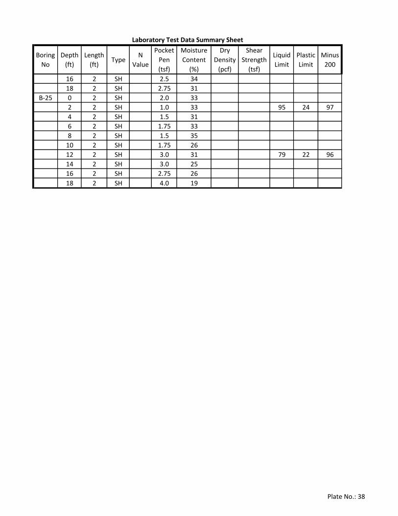
Boring
No
Depth
(ft)
Length
(ft)Type
N
Value
Pen
(tsf)
Moisture
Content
(%)
Dry
Density
(pcf)
Shear
Strength
(tsf)
Liquid
Limit
Plastic
Limit
Minus
200
Laboratory Test Data Summary Sheet
16 2 SH 2.5 34
18 2 SH 2.75 31
B-25 0 2 SH 2.0 33
2 2 SH 1.0 33 95 24 97
4 2 SH 1.5 31
6 2 SH 1.75 33
8 2 SH 1.5 35
10 2 SH 1.75 26
12 2 SH 3.0 31 79 22 96
14 2 SH 3.0 25
16 2 SH 2.75 26
18 2 SH 4.0 19
Plate No.: 38