project manual volume i of i and summaries/bid... · bid packages for this project will be...
TRANSCRIPT

Consolidated School District #158 Huntley High School Athletic Field Improvements
Bid Release #2
Project Manual Volume I of I
Architect
Wold Architects and Engineers 110 North Brockway Street
Two Hundred Twenty Palatine, IL 60067
Construction Manager
Lamp Incorporated 460 North Grove Avenue
Elgin, IL 60120
March 22, 2013

Huntley High School Athletic Field Improvements – Bid Release #2 Table of Contents – Page 1 of 3
Consolidated School District #158 Huntley High School Athletic Field Improvements
Bid Release #2
TABLE OF CONTENTS Construction Manager’s Manual
SECTION PAGES NOTICE TO BIDDERS 1 INSTRUCTIONS TO BIDDERS 5 SCHOOL REQUIREMENTS 1 SAFETY REQUIREMENTS 8 SAFETY VIOLATION SCHEDULE 1 PREVAILING WAGE CHART 7 SCOPE REVIEW MEETINGS 1 SCHEDULE 1 SITE STAGING DIAGRAM 1 SOIL BORING LOCATION AND RESULTS 59 WORK SCOPES GENERAL SCOPE OF WORK 7 EXCAVATION 02B-2 8 ASPHALT PAVING 02D-2 3 LANDSCAPING 02F-2 2 FENCING 02G-2 2 RUNNING TRACK SURFACE 02H-2 2 ATHLETIC EQUIPMENT 11A-2 2 ELECTRICAL 16A-2 3 BID FORMS TO BE ISSUED BY ADDENDUM PUBLIC BIDDING CERTIFICATES 2 LABOR RATE SHEET 1 BACKGROUND AUTHORIZATION 1 LIST OF SUBCONTRACTORS / SUPPLIERS 1 VOLUNTARY ALTERNATES 1 BID DAY LABEL 1 A132 - 2009 CONTRACTOR AGREEMENT FORM 8 A232 – 2009 GENERAL CONDITIONS 56 PAY REQUEST FORM 1 TEXTURA INFORMATION 2 DIVISION 01 SECTION 011000 – SUMMARY OF WORK 3 SECTION 012100 – ALLOWANCES 3 SECTION 012200 – UNIT PRICES 2
Huntley High School Athletic Field Improvements – Bid Release #2 Table of Contents – Page 2 of 3
SECTION 012300 – ALTERNATES 2 SECTION 012600 – MODIFICATION PROCEDURES 4 SECTION 012900 – APPLICATIONS FOR PAYMENT 4 SECTION 013100 – PROJECT MANAGEMENT 9 SECTION 013300 – SUBMITTALS 6 SECTION 013400 – SHOP DRAWINGS, PROD. DATA & SAMPLES 4 SECTION 014000 – QUALITY REQUIREMENTS 9 SECTION 014200 – REFERENCES 6 SECTION 014500 – CUTTING AND PATCHING 4 SECTION 014533 – STRUCTURAL TESTING AND SPECIAL INSPECTION 6 SECTION 015000 – TEMPORARY FACILITIES 17 SECTION 015100 – FIELD ENGINEERING 9 SECTION 016100 – PRODUCT SUBSTITUTIONS 3 SECTION 017000 – CLOSEOUT PROCEDURES 4 SECTION 017100 – CLEANING 2 SECTION 017200 – PROJECT RECORD DOCUMENTS 5 SECTION 017300 – OPERATIONS AND MAINTENANCE 9 SECTION 017400 – WARRANTIES AND BONDS 2 SECTION 017900 – DEMONSTRATION AND TRAINING 6 DIVISION 02 SECTION 025310 – ASPHALT CONST. SPECIFICATION RECOMMENDATIONS 18 SECTION 028210 – CHAIN LINK FENCES AND GATES 7 DIVISION 03 SECTION 031000 – CONCRETE FORMING AND ACCESSORIES 4 SECTION 031510 – POST-INSTALLED ANCHORS 5 SECTION 032000 – CONCRETE REINFORCING 5 SECTION 033000 – CAST-IN-PLACE CONCRETE 14 DIVISION 05 SECTION 051200 – STRUCTURAL STEEL FRAMING 6 DIVISION 06-10 NOT USED DIVISION 11 SECTION 114800 – EXTERIOR ATHLETIC EQUIPMENT 3 DIVISION 12-25 NOT USED DIVISION 26 SECTION 260500 – COMMON WORK RESULTS FOR ELECTRICAL 3 SECTION 260519 – LOW VOLTAGE ELECTRICAL POWER CONDUCTORS 2 SECTION 260526 – GROUNDING AND BONDING FOR ELECTRICAL SYSTEMS 4 SECTION 260529 – HANGERS AND SUPPORTS FOR ELECTRICAL SYSTEMS 4 SECTION 260533 – RACEWAY AND BOXES FOR ELECTRICAL SYSTEMS 5 SECTION 260553 – IDENTIFICATION FOR ELECTRICAL SYSTEMS 4 SECTION 260923 – LIGHTING CONTROL DEVICES 2 SECTION 262200 – LOW VOLTAGE TRANSFORMERS 3 SECTION 262416 – PANELBOARDS 4 SECTION 262726 – WIRING DEVICES 4 SECTION 262816 – ENCLOSED SWITCHES AND CIRCUIT BREAKERS 3
Huntley High School Athletic Field Improvements – Bid Release #2 Table of Contents – Page 3 of 3
DIVISION 27-30 NOT USED DIVISION 31 SECTION 311000 – SITE CLEARING 6 SECTION 312000 – EARTH MOVING 12 SECTION 312213 – ROUGH GRADING 4 SECTION 312219 – SYNTHETIC TURF FIELD FINISH GRADING 3 SECTION 312319 – DEWATERING 5 SECTION 315000 – EXCAVATION SUPPORT AND PROTECTION 5 DIVISION 32 SECTION 321216 – ASPHALT PAVING 10 SECTION 321313 – CONCRETE PAVING 14 SECTION 321373 – CONCRETE PAVING JOINT SEALANTS 5 SECTION 321815 – SYNTHETIC TURF FIELD UNDER DRAIN SYSTEM 3 SECTION 321816 – POURED URETHANE SPORTS SURFACES 4 SECTION 329200 – LAWNS AND GRASSES 6 SECTION 334100 – STORM SEWERS 13

Consolidated School District 158 650 Academic Drive
Algonquin, Illinois 60102 (847) 659-6158 • www.district158.org
NOTICE - Huntley High School Athletic Field Improvements – Bid Release #2 Consolidated School District #158 will receive sealed bids for the following trade packages Excavation (includes demolition, site utilities, and concrete), Landscaping, Asphalt Paving, Fencing, Track Surface, Athletic Equipment, and Electrical for the Huntley High School Athletic Field Improvements – Bid Release #2 project until 3:00 p.m. local time on April 10, 2013 at the District Office, 650 Academic Drive, Algonquin, Illinois, 60102, at which time and place all bids will be publicly opened and read aloud. Proposals complying with the bid documents will be received for the projects until the specified closing time. Bids shall be submitted on or before the specified closing time in an opaque sealed envelope marked “Huntley High School Athletic Field Improvements - Bid Release #2” on the outside and addressed to: Dr. John Burkey, Superintendent of Schools, Consolidated School District No. 158, Administrative Office, 650 Academic Drive, Algonquin, Illinois 60102. Bids shall be opened publicly and the contents announced at the specified closing time and at the location immediately above. Bids received after stated time will not be accepted and will be returned unopened. Make proposals on the bid forms supplied in the Project Manual. No oral, telegraphic or telephonic proposals or modifications will be considered. Submit with each bid, a certified check or acceptable bidder’s bond payable to Consolidated School District #158 in an amount equal to ten percent (10%) of the total bid. The successful bidder will be required to furnish satisfactory Labor and Material Payment Bond, and Performance Bond. All bids submitted shall be valid for a period of at least (60) sixty days from the date of bid opening. The only alterations, which may be allowed, will be those approved by the Board of Education. No immediate decision shall be rendered concerning the bids submitted at time of opening. The Bidder shall be actively engaged in work of the nature of the services for which bid is submitted as described in the bid specifications and shall have adequate equipment and personnel to do the work. Lamp Incorporated Qualification forms must be submitted to Lamp Incorporated by April 5, 2013. Qualification forms are available with the bidding documents on GradeBeam. The Board of Education of Consolidated School District No. 158 reserves the right to reject any or all bids or parts thereof, to waive any irregularities or informalities in the bidding procedures and to award the contracts in a manner serving the best interest of the school district. All bidders must comply with the applicable Illinois Law requiring the payment of prevailing wages by all contractors working on public projects, and bidders must comply with the Illinois Statutory requirements regarding labor and bidding, including Equal Opportunity Laws. Prospective bidders may obtain bid documents for their use and submission by contacting Lamp Incorporated ([email protected] or 847-741-7220 x324) and requesting an Invitation to Bid from GradeBeam. Bidders may download drawings for free from GradeBeam. Lamp will be utilizing GradeBeam for the entire bidding process, including addenda, all interested bidders MUST contact Lamp to access the Gradebeam website. Bidding documents will be on file and may be obtained from the Consolidated School District 158 website (www.district158.org) or by calling the office of the Director of Operations and Maintenance, 650 Academic, Algonquin, Illinois 60102, telephone (847) 659-6163, fax (847) 659-6126. A pre-bid meeting will be held at 3 P.M. on April 1st at the Huntley High School Athletic Fields, 13719 Harmony Road, Huntley, Illinois. Board of Education CONSOLIDATED SCHOOL DISTRICT #158

Huntley High School Athletic Field Improvements – Bid Release #2 Invitation To Bidders – Page 1 of 5
INSTRUCTIONS TO BIDDERS
PROJECT DESCRIPTION: This project consists of replacing the stadium field with synthetic grass, expand the bleachers including a new press box, and re-configure the track at the Huntley High School Athletic Field in Huntley, IL. Bid Packages for this project will be Excavation 02B-2, Asphalt Paving 02D-2, Landscaping 02F-2, Fencing 02G-2, Track Surface 02H-2, Athletic Equipment 11A-2, and Electrical 16A-2.
PROPOSALS: a. Bids are invited from qualified Trade Contractors for their approved areas of
construction for this Project as specified in the Project Manual and in the Construction Manager’s Manual.
Sealed bids, submitted in duplicate, for Trade Packages Excavation 02B-2, Asphalt Paving 02D-2, Landscaping 02F-2, Fencing 02G-2, Track Surface 02H-2, Athletic Equipment 11A-2, and Electrical 16A-2 should be delivered by 3:00 pm, Wednesday, April 10, 2013, to:
Dr. John Burkey Superintendent of Schools Consolidated School District 158 650 Academic Drive Algonquin, IL 60102
b. A complete bid consists of 2 of each of the following:
1. Completely filled in, signed, and sealed bid forms for the Trade Contractor’s Work Scope
2. A completed bid bond or other bid security (one copy must have company seal) 3. The public bidding certificates filled in, signed, and notarized 4. The Labor Rate Sheet filled in for each of the Trade Contractor’s associated
labor classifications 5. Criminal Background check authorization form 6. Voluntary Alternate Bid form only if the Contractor wants to submit an alternate
method not called for in the Bidding Documents
c. The information as listed above shall be placed in an opaque envelope and addressed to Dr. John Burkey as shown above, using the supplied bid day label. The outside of the envelope shall also contain the Bidder’s name and address, name of the project “Huntley High School Athletic Field Improvements – Bid Release #2”, the Trade Package that is being bid, and the time of the bid opening. If the Trade Contractor wants to provide combination bids, there is space on each bid form to do this.

Huntley High School Athletic Field Improvements – Bid Release #2 Invitation To Bidders – Page 2 of 5
d. Bids will be opened and read immediately after, at the Consolidated School District 158’s administration office, 650 Academic Drive, Algonquin, IL 60102. Bidders are invited to be present at the bid opening.
PRE-BID MEETING: A non-mandatory Pre-bid Meeting has been scheduled for Monday, April 1st at 3:00 PM at Huntley High School; gather at the concessions building near the athletic stadium on the South side of the building at that time. It is strongly urged that all bidders attend this meeting to fully understand the project existing conditions and requirements. Bidders failing to demonstrate a thorough understanding of the existing conditions at the scope review will be rejected. BID DOCUMENTS: Copies of Bidding Documents may be obtained by requesting an Invitation to Bid from GradeBeam. Lamp Incorporated will be using GradeBeam for the entire bidding process. Bidding documents may also be obtained from the Consolidated School District 158 web site.
INTERPRETATIONS: No oral interpretations will be made to any Bidder as to the meaning of the Specifications or the Drawings. Every request for an interpretation shall be made in writing to the Construction Manager. Send all questions to Tom McGrath at Lamp Incorporated via email at [email protected]. Any inquiry received seven or more days prior to the date fixed for the opening of Bids will be given consideration. Every interpretation made will be in the form of an Addendum to the Bidding Documents, which will be on file in the office of the Construction Manager at least two days before the Bids are opened and will be available to all Bidders on GradeBeam. Copies of these Addenda shall become part of the Contract Documents and all Bidders shall be bound by such Addenda whether or not received by the Bidders.
BID GUARANTEE: A Bid Guarantee, which shall be not less than 10 percent of the amount of the Base Bid, must accompany each Bid and at the option of the Bidder, may be a Certified Check, Bank Draft, or a Bid Bond on A.I.A. Form A-312, as edited by the General Conditions (see Exhibit A), secured by a Guarantee or Surety Company. No Bid will be considered unless it is so guaranteed. Certified Check or Bank Draft must be made payable to the order of Board of Education Consolidated School District # 158. Cash deposits will not be accepted. Such Bid Guarantee shall be submitted with the understanding that it shall guarantee that: a. The Bidder will not withdraw their Bid within 60 days after the date of the opening of
Bids. b. That the successful Bidder will enter into a formal Contract with the Owner and give
such bonds as are required by the GENERAL CONDITIONS.
Huntley High School Athletic Field Improvements – Bid Release #2 Invitation To Bidders – Page 3 of 5
c. In the event the Bid is withdrawn within the 60 day period after the date of the Bid Opening, the Bidder shall be liable to the Owner for the full amount of the Bid Guarantee, and the Owners shall have the right to retain the proceeds of said Bid Guarantee to apply on the account of damages and excess costs which they may incur because of such withdrawal.
d. In case the Bid Guarantee is the form of a Certified Check or Bank Draft, the Owner
may make such disposition of same as will accomplish the purpose for which submitted. Certified checks or Bank Drafts of all but the three lowest Bidders will be returned as soon as practical after the opening of the Bids.
PREVAILING WAGE: Consolidated School District 158 is required to pay prevailing wages on all projects. All Trade Contractors shall submit their proposal based upon the local prevailing wage rate as published by the Illinois Department of Labor and adopted by the School District. Certified payroll request will be required for each pay request as required by the State of Illinois law. BIDDING CERTIFICATES: The Trade Contractor in submitting their proposals shall include the public bidding certificates found within the Construction Manager’s Manual. The Certificates of Bidder Eligibility, Compliance with Illinois Drug-Free Workplace Act, Sexual Harassment Policy, Equal Employment, Public Works Employment Act, Prevailing Wage, and Non-Collusion must be included with the Trade Contractor’s bid proposal.
QUALIFICATION FORMS: All Trade Contractors submitting bids on the above project will have been qualified by Lamp Incorporated on Lamp’s Qualification form for the year 2013. If not, a Qualification Statement will be submitted to Lamp Incorporated prior to April 5th, 2013. All information requested on the form must be completed. This form can be requested or found on GradeBeam with the bidding documents. AWARD OF CONTRACTS - REJECTION OF BIDS: a. Contracts will be awarded to the responsible Bidder submitting the lowest proposal
complying with the conditions of the Bidding Documents, provided their Bid is reasonable and it is to the best interest of the Owner to accept it. The Bidder to whom the Contract is awarded will be notified at the earliest practicable date. The Owner, however, reserves the right to reject any and all Bids and to waive any informality, irregularity, or qualifications in the Bids received whenever such rejection or waiver is in the best interest of the Owner.
b. The Owner also reserves the right to reject the Bid of any Bidder who:
1. Has previously failed to perform properly. 2. Has failed to complete on time Contracts of similar nature. 3. Is not in a position to perform the work required promptly.

Huntley High School Athletic Field Improvements – Bid Release #2 Invitation To Bidders – Page 4 of 5
4. Has habitually, and without just cause, neglected the payment of bills or otherwise disregarded his obligations to subcontractors, material suppliers, and/or employees.
c. In determining the lowest responsible Bidder, the following elements, in addition to those heretofore mentioned, will be considered, whether the Bidder involved: 1. Maintains a permanent place of business. 2. Has adequate plant, equipment, and men available to do the work properly and
expeditiously. 3. Has suitable financial resources to meet the obligations incidental to the work. 4. Has appropriate technical experience.
d. The Owner reserves the right to consider as unqualified to perform the Trade
Contract Work any Bidder who does not habitually perform with his own forces the branches of the work for which he is submitting his bid.
e. The ability of a Bidder to obtain a Performance and Payment Bond shall not be
regarded as the sole test of such Bidder’s competency or responsibility.
PERFORMANCE AND PAYMENT BOND, EXECUTION OF CONTRACT: a. Subsequent to the award and within ten days after the Agreement forms are
presented for signature, successful Bidder shall sign the Agreement and deliver it to the Owner in such number of counterparts as the Owner may require. The Agreement will be on A.I.A. Document A132 2009 Edition as edited.
b. Having satisfied all conditions of the award as set forth elsewhere in these
Documents, successful Bidders shall, within the ten days specified in “a” above, furnish a Performance and a Labor and Material Payment bond each in the amount of the Contract as awarded, as a security for the faithful performance of the Contract, and for the Payment of all persons, firms, or corporations to whom the Contractor may become legally indebted for labor, materials, tools, equipment, or services, of any nature, employed or used by him in performing the work. Such bonds shall be in the form of A.I.A. Document A312, as edited by the General Conditions (Exhibit A) and shall bear the same date as, or a date subsequent to, the date of the Contract Agreement.
c. Each Bidder must be bondable at time bids are due and he shall state so in his bid.
d. The failure of successful Bidders to execute such Contract and to supply the
required Bonds within ten days after the prescribed forms are presented for signature or if bonding company finds that a Bidder is NOT bondable, shall constitute a default, and the Owner may either award the Contract to the next responsible Bidder or re-advertise for Bids, and may charge against such Bidder the difference between amount of his Bid and amount for which the Contract for the work is subsequently executed, irrespective of whether the amount thus due exceeds amount of his Bid Guarantee.

Huntley High School Athletic Field Improvements – Bid Release #2 Invitation To Bidders – Page 5 of 5
FEES FOR CONTRACT CHANGES: Trade Contractors shall agree that on all changes to the construction involving costs, either extra items or credit items, the percentages as described in Section 7.5.1 of the General Conditions will be added or deducted for the actual cost of the work for their overhead and profit. LIQUIDATED DAMAGES: August 14, 2013 is the date by which the District requires installation to be completed. If the critical path of the schedule leading to the completion date is delayed by the contractor, liquidated damages of $1,000.00 per calendar day will be assessed to the contractor for every day beyond the specified date that installation is not complete. If the completion date is missed the contractor is liable for consequential damages.
CONSTRUCTION TIME: a. The Trade Contractor shall commence work on the date of Notice to Proceed and
Letter of Intent and shall fully complete ALL work in a diligent and professional manner. It is Consolidated School District 158’s intention to issue a Letter of Intent on April 18, 2013, for work to begin shortly thereafter.
b. Work shall be completed per accepted contract proposal. c. Trade Contractors shall cooperate with the Owner and Construction Manager at all
times and coordinate construction work to maintain the safety, health, and welfare of students, staff, and workers.
d. If awarded a Contract, the Contractor agrees to begin shop drawings, order
materials, perform construction, and complete the work as shown on the Construction Manager’s schedule for this project.
e. In signing the Agreement, the Contractor further agrees to make every effort,
including working overtime, weekends and/or evenings, and to pay for expediting material and equipment, to meet the schedule.
f. The Contractor also agrees to pay for additional costs incurred by other Trade
Contractors if they are required to accelerate their schedule due to this Contractor not maintaining their portion of the project schedule.

Huntley High School Athletic Field Improvements – Bid Release #2 School Requirements - Page 1 of 1
SCHOOL REQUIREMENTS School will be in session while this project is in progress. There should not be any contact with the students or staff. Use of the school’s toilet will not be allowed. Temporary toilets will be located near the work area. Trash dumpsters will also be located near each work area. Use of the kitchen facilities, lunchroom, teacher’s lounge, and vending machines is prohibited. Wear school or District identification badges at all times when on the project site. Clean up work area at the end of each day and secure all tools and material to be left on the job site. All open trenches will be filled in at the end of the day or a secure fence will be installed around the open trench and equipment. The students will be in school during construction of this project therefore alcohol consumption, smoking, and profanity is strictly prohibited on school property.
Huntley High School Athletic Field Improvements – Bid Release #2 Site Safety Requirements and Procedures - Page 1 of 8
SITE SAFETY REQUIREMENTS AND PROCEDURES
The proceeding information addresses expectations of Subcontractors and Tier Subcontractors (herein after called subcontractors) performing work on Lamp Incorporated projects. Lamp Incorporated believes that through a concentrated effort by subcontractors, a safe and successful project will be achieved. Each subcontractor working on Lamp Incorporated projects are obligated to comply with all Federal, State and Local safety requirements, Site Specific Safety Programs, and any Owner Safety Requirements (herein after called safety requirements). These combined safety requirements constitute the minimum level of performance expected from each employer and his employees or their subcontractors or agents. All shall adhere to these requirements for the performance of their work on Lamp Incorporated projects designed to promote and to insure the projects safe completion. COMPLIANCE In accordance with the OSHA requirements, each subcontractor shall protect the employment and places of employment of each of his employees engaged in construction work by complying with the appropriate standards prescribed in the applicable standards. Subcontractors shall hold each of their agents, vendors, tier subcontractors and suppliers responsible for compliance with these safety requirements. Subcontractors shall include these safety requirements in contracts with all tier subcontractors and suppliers. Entry onto project, property, or the job site constitutes acknowledgement by the subcontractor, subcontractor employees or invitee of their obligation to adhere to these safety requirements. Each subcontractor shall establish and maintain an effective safety and health program that includes all items outlined in this document. The subcontractor shall be solely responsible for implementing the safety program and shall have sole responsibility for monitoring the work of its employees, subcontractors, agents, vendors and suppliers to ensure compliance. COMPETENT PERSON Each subcontractor shall designate a competent person as defined by OSHA to implement and enforce the safety requirements. A competent person from each subcontractor must be on site whenever they have employees working on site, and the name of that person shall be submitted on the Subcontractor Daily Report. Each subcontractor is required to maintain this position, and a competent person(s) will remain on-site until the completion of their work. The subcontractor shall not relinquish or defer responsibility for project safety to his own or subcontractor employees at any time under any circumstances. OSHA AND STATE AGENCY INSPECTIONS If after an inspection, a subcontractor receives any citation(s), a copy of all citations shall be immediately given to Lamp Incorporated. MEETINGS
Preconstruction Meeting Lamp Incorporated will request the subcontractor’s attendance at a Preconstruction Meeting with the Lamp Incorporated project team. The purpose of this meeting is to review expectations, schedule, coordination, quality, safety and other concerns. Weekly Project Meeting Project meetings will be conducted on site. The date and time of these meetings will be determined by the project team. Attendance is expected from each subcontractor unless excused by Lamp Incorporated.

Huntley High School Athletic Field Improvements – Bid Release #2 Site Safety Requirements and Procedures - Page 2 of 8
Incident Review Meeting Following an incident, Lamp Incorporated may request a meeting be held with the parties involved to discuss the incident in more detail. Requested subcontractors shall attend and participate in the investigation, discussion, and to develop an action plan. VIOLATIONS If a subcontractor or invitee is found non-compliant to any of the safety requirements, he/she will not be allowed on the job site. Any resulting damages (including damage for delay) will be paid for in accordance with the subcontract. If Lamp Incorporated deems it is necessary to stop work being performed due to the nature of a violation, work will be halted until the subcontractor corrects the violations. Any costs or delays in schedule incurred by the stoppage of work due to the Safety and Health violation will be the sole responsibility of the violating subcontractor. If violations of the safety requirements are observed, the responsible contractor shall be informed orally for immediate correction. It is the sole responsibility of the subcontractor to devise and implement the correction. The subcontractor shall be given a reasonable amount of time to correct the violation(s). The time period allowed shall reflect the severity of the violation(s) and the urgency to abate, and in some cases the corrective action might be immediate. If the subcontractor fails to correct the violation within the reasonable amount of time specified, Lamp Incorporated may take a number of actions including but not limited to:
A meeting will be conducted with the subcontractor’s supervisor and the Lamp Incorporated Project Team. The meeting should conclude in a documented agreement outlining the subcontractor’s intended corrective actions and timeframe for implementation.
Removal of unsafe condition by using other work forces, the cost of which will be reimbursed through back charges or provisions of the contract.
Removal of subcontractor personnel, including field supervision if necessary. A letter of non-compliance stating that the subcontractor is in violation sent to the subcontractor’s
office with a copy to their insurance company. Lamp Incorporated may exercise its option to terminate all or part of the contract with the
subcontractor for inadequate safety performance or failure to fulfill any of the safety requirements of the contract.
EMERGENCY MEDICAL FACILITY Each subcontractor is responsible to establish an Emergency Medical Facility for use by their injured employees. The facility to be used shall be communicated to their employees. The subcontractor is responsible for all costs borne out of medical treatment, substance abuse testing and any other associated costs (Lamp Incorporated is not to be charged for any treatment costs). Each subcontractor is to provide an appropriate sized First Aid kit that is maintained and adequately stocked. The location of the kit shall be shared with the crew.
DOCUMENTATION AND REPORTING SITE ORIENTATION Each subcontractor employee, before starting work, is to be orientated by the subcontractor on the safety requirements established for the project. Upon completion of the training, the individual will be given a sticker to place on their hard hat in a visible location. If an individual is found on-site without having received the training, that person will be removed from the project for the remainder of the day, and the crew foreman may be disciplined. SAFETY SUBMITTALS
Each subcontractor and tier subcontractor shall submit a copy of their Hazard Communication Program and Material Safety Data Sheets (applicable to the site) to the Project Team. Each subcontractor shall notify their employees of the location of the Hazard Communication Program and MSDS. Lamp Incorporated shall be notified when Hazardous Materials will be used and

Huntley High School Athletic Field Improvements – Bid Release #2 Site Safety Requirements and Procedures - Page 3 of 8
what protective methods will be used to protect those employees directly involved and those employees who may become exposed. The competent person for the subcontractor involved will be responsible for monitoring use and compliance by its employees with the protective methods devised.
In accordance with OSHA, each subcontractor shall submit a Safety Plan to Lamp Incorporated prior to the start of their work.
INSPECTIONS In accordance with OSHA, each subcontractor shall perform frequent and regular safety inspections of their work area(s) by a competent person. A copy of the report or documented inspection shall be submitted to Lamp Incorporated whenever the inspection is completed. Subcontractor supervisors shall take immediate action to correct violations, unsafe practices and unsafe conditions. The subcontractor will be solely responsible to review/monitor the work area/location of all their employees on a regular basis during the performance of work. TOOLBOX TALKS Each subcontractor shall conduct weekly "toolbox" safety meetings relevant to the work being performed for their employees. A copy of the toolbox talk or a description of the topic discussed along with all attendee’s names shall be submitted to Lamp Incorporated. INCIDENT REPORTING Subcontractors are responsible to immediately notify Lamp Incorporated of all incidents including personal injuries and illnesses, project property losses or damages, and incidents involving the public or their property. Each subcontractor is required to investigate all incidents incurred by their employees, or incidents that are the result of their operations. Each subcontractor shall provide to Lamp Incorporated an “Incident Investigation Report” within 24 hours of the occurrence. SUBSTANCE ABUSE POLICY Lamp Incorporated is committed to providing a safe work environment. The illegal use or abuse of drugs and or alcohol constitutes a threat to the safety and health of employees and the general public. Each subcontractor shall establish and maintain an effective substance abuse program pursuant to the Contract Documents and the Substance Abuse Prevention on Public Works Act, 820 ILCS 265/1 et seq . Drug and alcohol testing may be required of subcontractor employees in the following situations:
If Lamp Incorporated has reasonable suspicion that the employee is under the influence of drugs or alcohol
If the employee has sustained a work-related injury requiring outside medical attention If the employee has caused or contributed to another employee being injured in a work-related
incident If the employee has caused or contributed to a work-related incident resulting in, or which has the
potential to result in, property damage If the employee was involved in a “near miss” (defined as an occurrence that has the attributes of
an incident, yet has no apparent damage to person or property) * Subcontractor employees who fail to provide proof of a required drug and alcohol test will not be permitted on-site. All costs associated with any substance abuse testing are the responsibility of the subcontractor.
SITE SPECIFIC SAFETY ITEMS GENERAL REQUIREMENTS

Huntley High School Athletic Field Improvements – Bid Release #2 Site Safety Requirements and Procedures - Page 4 of 8
Subcontractors must report to the Lamp Incorporated Project Team any safety concerns, observed conditions or violations of job safety, regardless of whether they are within the observer's power or responsibility to correct.
Subcontractors shall assure that supervisory employees have a good working knowledge of applicable safety requirements as they pertain to their areas, and encourage all employees to improve their accident prevention awareness.
Smoking is prohibited at any time on the Lamp Incorporated job site. (No exceptions) The use of personal radio headsets (I-pods/MP3 players, etc.) while on-site is not allowed. Radios are not permitted in work areas adjacent to occupied spaces or when the project does not
allow their use. The Lamp Incorporated project superintendent will determine radio use in stand-alone buildings.
Glass bottles or containers are not allowed on site. CLEAN UP
Each subcontractor shall be responsible for daily clean up during and after installation of his materials and shall leave their areas broom swept.
Each subcontractor is responsible to provide manpower to move their trash and debris to an area designated by Lamp Incorporated. If debris is not removed on a timely basis, or after appropriate warning, Lamp Incorporated will provide people to remove the debris and the responsible subcontractor (s) will be responsible for all costs incurred.
TRAFFIC CONTROL
Signs shall conform to the requirements of 29 CFR 1926.200 and ANSI Z35.1-1968. Work on or adjacent to roadways must be protected in accordance with Illinois Statutes. IDOT
Certified Flagger control must be provided in accordance with Illinois Revised Statutes Chapter 121, Par. 314.2.
Signs and barricades must be removed immediately when no longer applicable or required. Parking in unauthorized areas will result in towing at the vehicle owners expense.
PERSONAL PROTECTIVE EQUIPMENT
Hard hats are to be worn 100% of the time, through all phases of construction, and shall be worn correctly. Equipment operators working outside of the equipment are required to wear hard hats 100% of the time.
Safety Glasses required 100% of the time, through all phases of construction. Eye and face protection when required, (i.e. overhead drilling or cutting,
chipping, welding, grinding, etc.) must meet applicable ANSI requirements. Hair which falls below the nape of the neck must be put under the hard hat or otherwise
controlled. Long pants and a shirt are to be worn. No shorts, tank tops, or any inappropriate
articles of clothing can be worn. If someone is wearing anything that Lamp Incorporated finds inappropriate, they will ask the individual to remove/cover the article. If they cannot or refuse to do so, they will be removed from the site.
Substantial leather footwear will be worn, preferably full height work boots at all times. “Gym Shoe” style work shoes are not permitted.
Fall Protection Equipment must meet and be maintained in accordance with OSHA Subpart M.
Hearing protection will be required in accordance with OSHA standards. If respirators are required, the contractor must be in compliance with all
applicable OSHA standards. When the use of respirators is required, proof of appropriate fit testing and training will be submitted by each subcontractor, upon the request of Lamp Incorporated.
Each subcontractor is solely responsible to supply their employees with Personal Protective Equipment

Huntley High School Athletic Field Improvements – Bid Release #2 Site Safety Requirements and Procedures - Page 5 of 8
EXCAVATION WORK All portions of work involving excavations, the excavating contractor must call JULIE and adhere
to the requirements of Subpart P--Excavations. (29 CFR 1926.650) Each contractor engaged in excavation work must have a person designated as the "Competent
Person" (as defined by OSHA) to enforce compliance with the OSHA Standards for Excavations. The name of that person and their qualifications will be submitted to Lamp Incorporated before work begins.
No employee shall enter a trench unless it has been determined by the Competent Person to be properly excavated and protected against collapse by means of sloping or benching, shoring, sheeting, the use of a trench box, or by other appropriate system.
Each employee will have the responsibility to stop work and notify others if they perceive that a problem with the excavation or protection system exists or develops.
Excavations will be back-filled as soon as possible after the completion of work. If excavations cannot be back-filled, the open trench shall be plated, barricaded, fenced and/or flagged to protect workers, pedestrians, and traffic.
CONFINED SPACE ENTRY
All activities involving Confined Space Entry shall comply with all applicable OSHA standards. Subcontractors are responsible to train their employees who are involved with confined space
entry. No one may enter a confined space area until properly trained. Prior to the start of such an entry, each subcontractor involved in the work shall develop a
Confined Space Entry Procedure. Subcontractors are required to identify all confined spaces on their project with a sign identifying
the area as a confined space. Subcontractors are responsible for providing and using all atmospheric testing devices.
EQUIPMENT REQUIREMENTS
All self propelled construction equipment shall be maintained, equipped and operated in accordance with all OSHA and manufacturers’ requirements. Material handling equipment (as defined by OSHA) shall be equipped with Roll-Over Protective Structures (ROPS) and seat belts.
Only authorized and trained personnel shall operate equipment. Cell phone use is prohibited while operating a piece of equipment. Equipment operators and truck drivers shall make a pre-shift safety inspection of their equipment.
Any conditions that effect safe operation shall be corrected before use. No personnel shall be transported or ride on equipment or vehicles that are not equipped with
seatsfor passengers. Any employee who is operating or using an aerial lift (scissor or boom) shall be properly trained in
the operation, use, and emergency procedures involved with the lift. Documentation shall be made available to Lamp Incorporated upon request.
Employees shall be tied off correctly in articulating boom lifts. Bi-directional earthmoving equipment and motor vehicles with an obstructed view to the rear shall
be equipped with a functioning warning horn, and/or, an automatic back-up alarm. Only trained and authorized personnel shall operate forklifts. Forklifts shall be operated in accordance with the manufacturer’s specifications and requirements. Operators will wear seatbelts during forklift operations.
CONCRETE AND MASONRY
All concrete and masonry operations shall be performed in accordance with 29CFR 1926 Subpart Q.
All concrete, masonry, or other silica-generating cutting process must be done with wet-methods. Grinding silica will be conducted with methods as to not expose surrounding employees to elevated levels of silica.

Huntley High School Athletic Field Improvements – Bid Release #2 Site Safety Requirements and Procedures - Page 6 of 8
Concrete subcontractors (or masonry subcontractor when applicable) are responsible for notifying Lamp Incorporated Project Team of any changes or modifications to anchor bolts and any issues related to concrete strength or performance.
LADDERS AND STAIRWAYS
Job made ladders must meet ANSI standards. No portable metal ladders are allowed. Damaged ladders must be removed from service immediately. All ladders are to be used correctly. A ladder or stairway is required at a point of access where there is a change in elevation greater
than 19”. Extension ladders must extend 3’ above the landing and be tied off. Each subcontractor shall provide ladder training for all employees using ladders. Stairs and platforms must be used to provide access to office, equipment, and material storage
trailers. Stairways must be kept free of flammable materials, stored materials or debris.
SCAFFOLDS
All scaffolds shall be erected, used, and dismantled in accordance with OSHA’s Subpart L and Local Codes.
Each contractor must have a person designated as the “Competent Person” (as defined by OSHA) to assure compliance with all requirements for scaffolding. The name of that person will be submitted to Lamp Incorporated on the Daily Report. No scaffold shall be erected, moved, dismantled, altered, or work performed from any scaffold except under the supervision of the competent person.
All scaffolds must be erected in accordance with manufacturer’s specifications and requirements.
FALL PROTECTION Unless superseded by a Site Specific Plan, subcontractors will comply with the fall protection
requirements as outlined in by OSHA (1926 Subpart M). Key elements include: Perimeter / guardrail cabling shall be no less than 3/8” IWRC-Galvanized, with a minimum of two
wire rope clamps at each connection. Perimeter cables and guard rail systems are not to be used as attachment points for fall arrest or restraint unless the subcontractor accepts the responsibility for the design, installation, inspection and all other applicable requirements.
If a subcontractor needs to take down a perimeter cable or guardrail, the subcontractor is required to notify the Lamp incorporated Site Superintendent.
Floor openings 2” or more, must be covered, marked to identify a hole, and secured. Covers are to withstand 2 times the intended load.
Personal fall protection equipment shall be inspected, in accordance with the manufacturers specifications, daily, and prior to each use for signs of wear and damage.
Any damaged equipment or equipment subjected to a fall shall be taken out of service. Subcontractor work that necessitates the use of either "Controlled Access Zones" or a "Fall
Protection Plan" are required to submit those plans to Lamp Incorporated prior to beginning work (for recordkeeping purposes).
CRANES AND RIGGING
The subcontractor in charge of the crane shall ensure that the capacity, ground conditions, and all other conditions are acceptable, and if are not, shall notify Lamp Incorporated in writing their proposal to implement any corrections or modifications necessary.
Cranes must have a current annual inspection. If the inspection certificate expires while the crane is on site, it must be re-inspected. Documentation of the inspections shall be submitted to the Lamp Incorporated Project Team upon request.
Subcontractors may be required to participate in “Pre-Lift” meetings at which time full cooperation

Huntley High School Athletic Field Improvements – Bid Release #2 Site Safety Requirements and Procedures - Page 7 of 8
is expected. The subcontractor must be prepared to discuss lifting procedures, crane selection and capacities, rigging, load weights and configuration and other pertinent items.
The swing radius of the crane must be barricaded or otherwise guarded by subcontractor using/operating crane.
Only one person is to signal the crane operator at a time (hand signals, radio, hard line, etc.). Loads shall be tag-lined, unless the use of the tagline would pose a greater hazard. Cell phone use is prohibited while operating a crane or by signal person. When overhead utilities are present, sufficient clearance distances must be maintained in
accordance with OSHA and ASME B 30.5. Multiple lifts of structural members must be done in accordance with OSHA standards and
coordinated with the Lamp Incorporated Project Team. Rigging shall be inspected prior to use and as necessary throughout the course of the day. If any rigging is found to be worn or damaged, it shall be removed from service immediately. Each
subcontractor is responsible for complying with rigging requirements set forth by OSHA, ASME and rigging manufacturers’.
Rigging equipment should never be used beyond its rated capacity. Stacked materials are to be kept neat and orderly. Materials shall be stacked in a manner to
prevent tipping, falling, shifting or rolling. STEEL ERECTION
All steel erection activities shall be in compliance with OSHA Subpart R. A written “site-specific erection safety plan” (to include fall protection) shall be submitted to Lamp
Incorporated prior to the start of work. When special or unusual hazards will be encountered (i.e. work over existing structures, near utilities or water), the contractor will clearly address these issues in the "site specific erection safety plan".
Perimeter cabling shall be no less than a minimum of 3/8” IWRC-Galvanized, with a minimum of two wire rope clamps at each connection.
Welders shall use appropriate welding hoods, not tinted face shields, and other required PPE. Welders’ certificates shall be submitted to Lamp Incorporated upon request.
If work is performed within or adjacent to occupied structures, the subcontractor will be required to make provisions for fire protection, and the safe removal of all welding fumes from the building. The methods shall be submitted to Lamp Incorporated prior to the start of the work.
FIRE PROTECTION AND HOT WORK PROCEDURES Daily, before any burning, welding, brazing, soldering or any other hot work is conducted, a Hot
Work Permit must be obtained from Lamp Incorporated. Terms of the permit must be adhered to. All welding and burning work shall be done in accordance with OSHA standards. The movement,
storage, and use of cylinders shall be done in accordance with OSHA standards. All personnel using gas welding or burning equipment will be fully trained in the use and
maintenance of the equipment. At minimum, a 10 pound dry chemical ABC fire extinguisher must be within 20 feet of any burning or welding operation. This fire extinguisher is provided by the subcontractor performing the work. A Fire Watch must be present during, and for no less than 60 minutes after the completion of the
work. Compressed air or gas shall not be used by an individual to clean their clothing. Flammable liquids shall be stored and dispensed in accordance with OSHA requirements. All containers must be FM approved or UL listed. The container must have a self closing lid and a
wire mesh flame arrester. If the can is damaged, it is to be removed from site. In accordance with the Hazard Communication Standard, containers will be clearly marked
showing the contents, hazard level and any special use or handling requirements. Flammable liquids will not be stored within enclosed structures such as buildings under
construction, storage trailers; tool sheds, in stairways or building exits/entrances. Observe all “NO OPEN FLAME” signs.

Huntley High School Athletic Field Improvements – Bid Release #2 Site Safety Requirements and Procedures - Page 8 of 8
Fire extinguishers which are provided by Lamp Incorporated are available for general use. They are generally located at entrances, stair wells, and on each floor. If a fire extinguisher is used, return it immediately to the project trailer to replace it with a fresh one. Do not place material in front of, or block extinguishers from view.
ELECTRICAL SAFETY
Installation of Temporary electric and lighting must comply with 29 CFR 1926 Subpart K. Each contractor will inspect their power tools and extension cords prior to each use. Damaged
equipment shall be removed from service Temporary electric must be protected by a GFCI. GFCI breakers and outlets will be tested periodically by the electrical contractor and a record of
the tests kept. The electrical contractor will maintain the record of the tests and provide to Lamp Incorporated upon request.
A GFCI must be used when using permanent power. Open conductors will be protected in conduit or equivalent when within 8 feet of a walking
surface. Wire for lighting within stairwells will be protected by conduit or wiring design. Unprotected open
conductors are not permitted.Temporary lighting will be provided in accordance with OSHA and contract requirements. Any additional lighting (task lighting) required will be provided by each contractor.
On a permanent outlet, a cover plate must be attached in order for the outlet to be utilized. Plugging into an outlet that does not have a cover plate is not permitted.
All live circuit panels must have an OSHA compliant panel cover on them. Never leave an unattended live panel open.
Work performed in proximity to overhead utilities Prior to the start of, and during the course of any work in proximity to overhead utilities, the
subcontractor shall make a thorough survey of the entire work site to determine the type and location of all utilities on the work site. The subcontractor must verify this information with Lamp Incorporated by notifying the Project superintendent and shall coordinate construction work in the vicinity of these utilities with the appropriate utility owner.
The subcontractor will be required to investigate any and all contingencies where contacting a utility could adversely affect any operation or render inoperative any protective apparatus in the surrounding area and submit a written procedure to Lamp Incorporated for protection or rerouting of critical systems.
The subcontractor shall make employees aware of any precautions and procedures to be followed while working in the proximity of any utility.
Working on equipment (Lockout / Tagout)
Each contractor whose work involves working on live equipment shall submit a plan in accordance with NFPA 70 E or a Lock-out/Tag-out program to Lamp Incorporated upon request.
Whenever work is to be done on a piece of equipment, including building equipment and or
contractors’ equipment, OSHA’s Controlled Hazardous Energy standard must be followed.

Huntley High School Athletic Field Improvements – Bid Release #2 Safety Violation Fine Schedule - Page 1 of 1
SAFETY VIOLATION FINE SCHEDULE
All Trade Contractors are subject to the safety violation fine schedule outlined below. First offenses will be issued a written violation warning; second offenses will be issued a written violation and fine; third offenses will result in expulsion from jobsite. Fines are required to be made payable to Lamp Incorporated, by Trade Contractor company check, signed by an officer of said company. Fines are due to be paid within 14 calendar days of date on Safety Violation form. Pay requests will not be processed until fine violation payment has been received by Lamp Incorporated. VIOLATION FINE
Hard Hat .................................. $100.00
Safety Glasses ......................... $100.00
GFCI Protection ....................... $100.00
Traffic/Parking .......................... $100.00
Tobacco Possession/Use ......... $100.00
Site Conduct (language) ........... $100.00
General Safety ......................... $100.00
Alcohol Possession/Use ........... $250.00 and permanent expulsion from jobsite
Drug Possession/Use ............... $250.00 and permanent expulsion from jobsite
Open Excavations .................... $250.00
Scaffold .................................... $250.00
Fall Protection .......................... $250.00
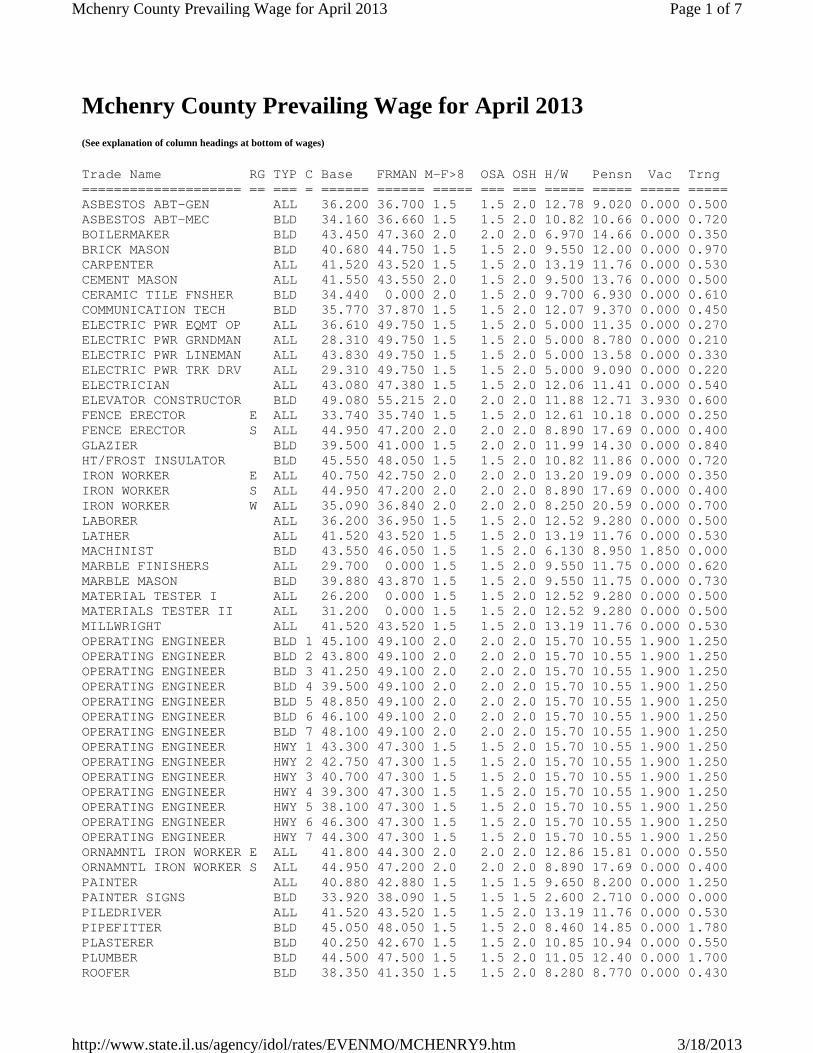
Mchenry County Prevailing Wage for April 2013 (See explanation of column headings at bottom of wages)
Trade Name RG TYP C Base FRMAN M-F>8 OSA OSH H/W Pensn Vac Trng ==================== == === = ====== ====== ===== === === ===== ===== ===== ===== ASBESTOS ABT-GEN ALL 36.200 36.700 1.5 1.5 2.0 12.78 9.020 0.000 0.500 ASBESTOS ABT-MEC BLD 34.160 36.660 1.5 1.5 2.0 10.82 10.66 0.000 0.720 BOILERMAKER BLD 43.450 47.360 2.0 2.0 2.0 6.970 14.66 0.000 0.350 BRICK MASON BLD 40.680 44.750 1.5 1.5 2.0 9.550 12.00 0.000 0.970 CARPENTER ALL 41.520 43.520 1.5 1.5 2.0 13.19 11.76 0.000 0.530 CEMENT MASON ALL 41.550 43.550 2.0 1.5 2.0 9.500 13.76 0.000 0.500 CERAMIC TILE FNSHER BLD 34.440 0.000 2.0 1.5 2.0 9.700 6.930 0.000 0.610 COMMUNICATION TECH BLD 35.770 37.870 1.5 1.5 2.0 12.07 9.370 0.000 0.450 ELECTRIC PWR EQMT OP ALL 36.610 49.750 1.5 1.5 2.0 5.000 11.35 0.000 0.270 ELECTRIC PWR GRNDMAN ALL 28.310 49.750 1.5 1.5 2.0 5.000 8.780 0.000 0.210 ELECTRIC PWR LINEMAN ALL 43.830 49.750 1.5 1.5 2.0 5.000 13.58 0.000 0.330 ELECTRIC PWR TRK DRV ALL 29.310 49.750 1.5 1.5 2.0 5.000 9.090 0.000 0.220 ELECTRICIAN ALL 43.080 47.380 1.5 1.5 2.0 12.06 11.41 0.000 0.540 ELEVATOR CONSTRUCTOR BLD 49.080 55.215 2.0 2.0 2.0 11.88 12.71 3.930 0.600 FENCE ERECTOR E ALL 33.740 35.740 1.5 1.5 2.0 12.61 10.18 0.000 0.250 FENCE ERECTOR S ALL 44.950 47.200 2.0 2.0 2.0 8.890 17.69 0.000 0.400 GLAZIER BLD 39.500 41.000 1.5 2.0 2.0 11.99 14.30 0.000 0.840 HT/FROST INSULATOR BLD 45.550 48.050 1.5 1.5 2.0 10.82 11.86 0.000 0.720 IRON WORKER E ALL 40.750 42.750 2.0 2.0 2.0 13.20 19.09 0.000 0.350 IRON WORKER S ALL 44.950 47.200 2.0 2.0 2.0 8.890 17.69 0.000 0.400 IRON WORKER W ALL 35.090 36.840 2.0 2.0 2.0 8.250 20.59 0.000 0.700 LABORER ALL 36.200 36.950 1.5 1.5 2.0 12.52 9.280 0.000 0.500 LATHER ALL 41.520 43.520 1.5 1.5 2.0 13.19 11.76 0.000 0.530 MACHINIST BLD 43.550 46.050 1.5 1.5 2.0 6.130 8.950 1.850 0.000 MARBLE FINISHERS ALL 29.700 0.000 1.5 1.5 2.0 9.550 11.75 0.000 0.620 MARBLE MASON BLD 39.880 43.870 1.5 1.5 2.0 9.550 11.75 0.000 0.730 MATERIAL TESTER I ALL 26.200 0.000 1.5 1.5 2.0 12.52 9.280 0.000 0.500 MATERIALS TESTER II ALL 31.200 0.000 1.5 1.5 2.0 12.52 9.280 0.000 0.500 MILLWRIGHT ALL 41.520 43.520 1.5 1.5 2.0 13.19 11.76 0.000 0.530 OPERATING ENGINEER BLD 1 45.100 49.100 2.0 2.0 2.0 15.70 10.55 1.900 1.250 OPERATING ENGINEER BLD 2 43.800 49.100 2.0 2.0 2.0 15.70 10.55 1.900 1.250 OPERATING ENGINEER BLD 3 41.250 49.100 2.0 2.0 2.0 15.70 10.55 1.900 1.250 OPERATING ENGINEER BLD 4 39.500 49.100 2.0 2.0 2.0 15.70 10.55 1.900 1.250 OPERATING ENGINEER BLD 5 48.850 49.100 2.0 2.0 2.0 15.70 10.55 1.900 1.250 OPERATING ENGINEER BLD 6 46.100 49.100 2.0 2.0 2.0 15.70 10.55 1.900 1.250 OPERATING ENGINEER BLD 7 48.100 49.100 2.0 2.0 2.0 15.70 10.55 1.900 1.250 OPERATING ENGINEER HWY 1 43.300 47.300 1.5 1.5 2.0 15.70 10.55 1.900 1.250 OPERATING ENGINEER HWY 2 42.750 47.300 1.5 1.5 2.0 15.70 10.55 1.900 1.250 OPERATING ENGINEER HWY 3 40.700 47.300 1.5 1.5 2.0 15.70 10.55 1.900 1.250 OPERATING ENGINEER HWY 4 39.300 47.300 1.5 1.5 2.0 15.70 10.55 1.900 1.250 OPERATING ENGINEER HWY 5 38.100 47.300 1.5 1.5 2.0 15.70 10.55 1.900 1.250 OPERATING ENGINEER HWY 6 46.300 47.300 1.5 1.5 2.0 15.70 10.55 1.900 1.250 OPERATING ENGINEER HWY 7 44.300 47.300 1.5 1.5 2.0 15.70 10.55 1.900 1.250 ORNAMNTL IRON WORKER E ALL 41.800 44.300 2.0 2.0 2.0 12.86 15.81 0.000 0.550 ORNAMNTL IRON WORKER S ALL 44.950 47.200 2.0 2.0 2.0 8.890 17.69 0.000 0.400 PAINTER ALL 40.880 42.880 1.5 1.5 1.5 9.650 8.200 0.000 1.250 PAINTER SIGNS BLD 33.920 38.090 1.5 1.5 1.5 2.600 2.710 0.000 0.000 PILEDRIVER ALL 41.520 43.520 1.5 1.5 2.0 13.19 11.76 0.000 0.530 PIPEFITTER BLD 45.050 48.050 1.5 1.5 2.0 8.460 14.85 0.000 1.780 PLASTERER BLD 40.250 42.670 1.5 1.5 2.0 10.85 10.94 0.000 0.550 PLUMBER BLD 44.500 47.500 1.5 1.5 2.0 11.05 12.40 0.000 1.700 ROOFER BLD 38.350 41.350 1.5 1.5 2.0 8.280 8.770 0.000 0.430
Page 1 of 7Mchenry County Prevailing Wage for April 2013
3/18/2013http://www.state.il.us/agency/idol/rates/EVENMO/MCHENRY9.htm

SHEETMETAL WORKER BLD 42.510 44.510 1.5 1.5 2.0 10.04 12.01 0.000 0.780 SIGN HANGER BLD 26.070 27.570 1.5 1.5 2.0 3.800 3.550 0.000 0.000 SPRINKLER FITTER BLD 49.200 51.200 1.5 1.5 2.0 10.25 8.350 0.000 0.450 STEEL ERECTOR E ALL 40.750 42.750 2.0 2.0 2.0 13.20 19.09 0.000 0.350 STEEL ERECTOR S ALL 44.950 47.200 2.0 2.0 2.0 8.890 17.69 0.000 0.400 STONE MASON BLD 40.680 44.750 1.5 1.5 2.0 9.550 12.00 0.000 0.970 TERRAZZO FINISHER BLD 35.510 0.000 1.5 1.5 2.0 9.700 9.320 0.000 0.400 TERRAZZO MASON BLD 39.370 42.370 1.5 1.5 2.0 9.700 10.66 0.000 0.550 TILE MASON BLD 41.430 45.430 2.0 1.5 2.0 9.700 8.640 0.000 0.710 TRAFFIC SAFETY WRKR HWY 28.250 29.850 1.5 1.5 2.0 4.896 4.175 0.000 0.000 TRUCK DRIVER ALL 1 35.850 36.400 1.5 1.5 2.0 7.200 6.000 0.000 0.150 TRUCK DRIVER ALL 2 36.000 36.400 1.5 1.5 2.0 7.200 6.000 0.000 0.150 TRUCK DRIVER ALL 3 36.200 36.400 1.5 1.5 2.0 7.200 6.000 0.000 0.150 TRUCK DRIVER ALL 4 36.400 36.400 1.5 1.5 2.0 7.200 6.000 0.000 0.150 TUCKPOINTER BLD 40.950 41.950 1.5 1.5 2.0 8.180 10.82 0.000 0.940 Legend:
Explanations
MCHENRY COUNTY FENCE ERECTOR (EAST) - That part of the county East and Northeast of a line following Route 31 North to Route 14, northwest to Route 47 north to the Wisconsin State Line. IRONWORKERS (EAST) - That part of the county East of Rts. 47 and 14. IRONWORKERS (SOUTH) - That part of the county South of Route 14 and East of Route 47. IRONWORKERS (WEST) - That part of the county West of Route 47. The following list is considered as those days for which holiday rates of wages for work performed apply: New Years Day, Memorial Day, Fourth of July, Labor Day, Thanksgiving Day, Christmas Day and Veterans Day in some classifications/counties. Generally, any of these holidays which fall on a Sunday is celebrated on the following Monday. This then makes work performed on that Monday payable at the appropriate overtime rate for holiday pay. Common practice in a given local may alter certain days of celebration. If in doubt, please check with IDOL. EXPLANATION OF CLASSES ASBESTOS - GENERAL - removal of asbestos material/mold and hazardous materials from any place in a building, including mechanical systems
RG (Region) TYP (Trade Type - All,Highway,Building,Floating,Oil & Chip,Rivers) C (Class) Base (Base Wage Rate) FRMAN (Foreman Rate) M-F>8 (OT required for any hour greater than 8 worked each day, Mon through Fri. OSA (Overtime (OT) is required for every hour worked on Saturday) OSH (Overtime is required for every hour worked on Sunday and Holidays) H/W (Health & Welfare Insurance) Pensn (Pension) Vac (Vacation) Trng (Training)
Page 2 of 7Mchenry County Prevailing Wage for April 2013
3/18/2013http://www.state.il.us/agency/idol/rates/EVENMO/MCHENRY9.htm

where those mechanical systems are to be removed. This includes the removal of asbestos materials/mold and hazardous materials from ductwork or pipes in a building when the building is to be demolished at the time or at some close future date. ASBESTOS - MECHANICAL - removal of asbestos material from mechanical systems, such as pipes, ducts, and boilers, where the mechanical systems are to remain. CERAMIC TILE FINISHER The grouting, cleaning, and polishing of all classes of tile, whether for interior or exterior purposes, all burned, glazed or unglazed products; all composition materials, granite tiles, warning detectable tiles, cement tiles, epoxy composite materials, pavers, glass, mosaics, fiberglass, and all substitute materials, for tile made in tile-like units; all mixtures in tile like form of cement, metals, and other materials that are for and intended for use as a finished floor surface, stair treads, promenade roofs, walks, walls, ceilings, swimming pools, and all other places where tile is to form a finished interior or exterior. The mixing of all setting mortars including but not limited to thin-set mortars, epoxies, wall mud, and any other sand and cement mixtures or adhesives when used in the preparation, installation, repair, or maintenance of tile and/or similar materials. The handling and unloading of all sand, cement, lime, tile, fixtures, equipment, adhesives, or any other materials to be used in the preparation, installation, repair, or maintenance of tile and/or similar materials. Ceramic Tile Finishers shall fill all joints and voids regardless of method on all tile work, particularly and especially after installation of said tile work. Application of any and all protective coverings to all types of tile installations including, but not be limited to, all soap compounds, paper products, tapes, and all polyethylene coverings, plywood, masonite, cardboard, and any new type of products that may be used to protect tile installations, Blastrac equipment, and all floor scarifying equipment used in preparing floors to receive tile. The clean up and removal of all waste and materials. All demolition of existing tile floors and walls to be re-tiled. COMMUNICATIONS TECHNICIAN Construction, installation, maintenance and removal of telecommunication facilities (voice, sound, data and video), telephone, security systems, fire alarm systems that are a component of a multiplex system and share a common cable, and data inside wire, interconnect, terminal equipment, central offices, PABX and equipment, micro waves, V-SAT, bypass, CATV, WAN (wide area network), LAN (local area networks), and ISDN (integrated system digital network), pulling of wire in raceways, but not the installation of raceways. MARBLE FINISHER Loading and unloading trucks, distribution of all materials (all stone, sand, etc.), stocking of floors with material, performing all rigging for heavy work, the handling of all material that may be needed for the installation of such materials, building of scaffolding, polishing if needed, patching, waxing of material if damaged, pointing up, caulking, grouting and cleaning of marble,
Page 3 of 7Mchenry County Prevailing Wage for April 2013
3/18/2013http://www.state.il.us/agency/idol/rates/EVENMO/MCHENRY9.htm

holding water on diamond or Carborundum blade or saw for setters cutting, use of tub saw or any other saw needed for preparation of material, drilling of holes for wires that anchor material set by setters, mixing up of molding plaster for installation of material, mixing up thin set for the installation of material, mixing up of sand to cement for the installation of material and such other work as may be required in helping a Marble Setter in the handling of all material in the erection or installation of interior marble, slate, travertine, art marble, serpentine, alberene stone, blue stone, granite and other stones (meaning as to stone any foreign or domestic materials as are specified and used in building interiors and exteriors and customarily known as stone in the trade), carrara, sanionyx, vitrolite and similar opaque glass and the laying of all marble tile, terrazzo tile, slate tile and precast tile, steps, risers treads, base, or any other materials that may be used as substitutes for any of the aforementioned materials and which are used on interior and exterior which are installed in a similar manner. MATERIAL TESTER I: Hand coring and drilling for testing of materials; field inspection of uncured concrete and asphalt. MATERIAL TESTER II: Field inspection of welds, structural steel, fireproofing, masonry, soil, facade, reinforcing steel, formwork, cured concrete, and concrete and asphalt batch plants; adjusting proportions of bituminous mixtures. OPERATING ENGINEER - BUILDING Class 1. Asphalt Plant; Asphalt Spreader; Autograde; Backhoes with Caisson Attachment; Batch Plant; Benoto (requires Two Engineers); Boiler and Throttle Valve; Caisson Rigs; Central Redi-Mix Plant; Combination Back Hoe Front End-loader Machine; Compressor and Throttle Valve; Concrete Breaker (Truck Mounted); Concrete Conveyor; Concrete Conveyor (Truck Mounted); Concrete Paver Over 27E cu. ft; Concrete Paver 27E cu. ft. and Under: Concrete Placer; Concrete Placing Boom; Concrete Pump (Truck Mounted); Concrete Tower; Cranes, All; Cranes, Hammerhead; Cranes, (GCI and similar Type); Creter Crane; Crusher, Stone, etc.; Derricks, All; Derricks, Traveling; Formless Curb and Gutter Machine; Grader, Elevating; Grouting Machines; Highlift Shovels or Front Endloader 2-1/4 yd. and over; Hoists, Elevators, outside type rack and pinion and similar machines; Hoists, One, Two and Three Drum; Hoists, Two Tugger One Floor; Hydraulic Backhoes; Hydraulic Boom Trucks; Hydro Vac (and similar equipment); Locomotives, All; Motor Patrol; Lubrication Technician; Manipulators; Pile Drivers and Skid Rig; Post Hole Digger; Pre-Stress Machine; Pump Cretes Dual Ram; Pump Cretes: Squeeze Cretes-Screw Type Pumps; Gypsum Bulker and Pump; Raised and Blind Hole Drill; Roto Mill Grinder; Scoops - Tractor Drawn; Slip-Form Paver; Straddle Buggies; Tournapull; Tractor with Boom and Side Boom; Trenching Machines. Class 2. Boilers; Broom, All Power Propelled; Bulldozers; Concrete Mixer (Two Bag and Over); Conveyor, Portable; Forklift Trucks; Highlift Shovels or Front Endloaders under 2-1/4 yd.; Hoists, Automatic; Hoists, Inside Elevators; Hoists, Sewer Dragging Machine; Hoists, Tugger Single Drum; Rock Drill (Self-Propelled); Rock Drill (Truck Mounted); Rollers, All; Steam Generators; Tractors, All; Tractor Drawn Vibratory Roller; Winch Trucks with "A" Frame. Class 3. Air Compressor; Combination Small Equipment Operator;
Page 4 of 7Mchenry County Prevailing Wage for April 2013
3/18/2013http://www.state.il.us/agency/idol/rates/EVENMO/MCHENRY9.htm

Generators; Heaters, Mechanical; Hoists, Inside Elevators; Hydraulic Power Units (Pile Driving, Extracting, and Drilling); Pumps, over 3" (1 to 3 not to exceed a total of 300 ft.); Low Boys; Pumps, Well Points; Welding Machines (2 through 5); Winches, 4 Small Electric Drill Winches; Bobcats (up to and including ¾ cu yd.) . Class 4. Bobcats and/or other Skid Steer Loaders (other than bobcats up to and including ¾ cu yd.); Oilers; and Brick Forklift. Class 5. Assistant Craft Foreman. Class 6. Gradall . Class 7. Mechanics. OPERATING ENGINEERS - HIGHWAY CONSTRUCTION Class 1. Asphalt Plant; Asphalt Heater and Planer Combination; Asphalt Heater Scarfire; Asphalt Spreader; Autograder/GOMACO or other similar type machines: ABG Paver; Backhoes with Caisson Attachment; Ballast Regulator; Belt Loader; Caisson Rigs; Car Dumper; Central Redi-Mix Plant; Combination Backhoe Front Endloader Machine, (1 cu. yd. Backhoe Bucket or over or with attachments); Concrete Breaker (Truck Mounted); Concrete Conveyor; Concrete Paver over 27E cu. ft.; Concrete Placer; Concrete Tube Float; Cranes, all attachments; Cranes, Tower Cranes of all types: Creter Crane: Crusher, Stone, etc.; Derricks, All; Derrick Boats; Derricks, Traveling; Dowell Machine with Air Compressor; Dredges; Formless Curb and Gutter Machine; Grader, Elevating; Grader, Motor Grader, Motor Patrol, Auto Patrol, Form Grader, Pull Grader, Subgrader; Guard Rail Post Driver Truck Mounted; Hoists, One, Two and Three Drum; Hydraulic Backhoes; Backhoes with shear attachments; Lubrication Technician; Manipulators; Mucking Machine; Pile Drivers and Skid Rig; Pre-Stress Machine; Pump Cretes Dual Ram; Rock Drill - Crawler or Skid Rig; Rock Drill - Truck Mounted; Rock/Track Tamper; Roto Mill Grinder; Slip-Form Paver; Soil Test Drill Rig (Truck Mounted); Straddle Buggies; Hydraulic Telescoping Form (Tunnel); Tractor Drawn Belt Loader (with attached pusher - two engineers); Tractor with Boom; Tractaire with Attachments; Trenching Machine; Truck Mounted Concrete Pump with Boom; Raised or Blind Hole Drills (Tunnel Shaft); Underground Boring and/or Mining Machines 5 ft. in diameter and over tunnel, etc; Underground Boring and/or Mining Machines under 5 ft. in diameter; Wheel Excavator; Widener (APSCO). Class 2. Batch Plant; Bituminous Mixer; Boiler and Throttle Valve; Bulldozers; Car Loader Trailing Conveyors; Combination Backhoe Front Endloader Machine (Less than 1 cu. yd. Backhoe Bucket or over or with attachments); Compressor and Throttle Valve; Compressor, Common Receiver (3); Concrete Breaker or Hydro Hammer; Concrete Grinding Machine; Concrete Mixer or Paver 7S Series to and including 27 cu. ft.; Concrete Spreader; Concrete Curing Machine, Burlap Machine, Belting Machine and Sealing Machine; Concrete Wheel Saw; Conveyor Muck Cars (Haglund or Similar Type); Drills, All; Finishing Machine - Concrete; Highlift Shovels or Front Endloader; Hoist - Sewer Dragging Machine; Hydraulic Boom Trucks (All Attachments); Hydro-Blaster; All Locomotives, Dinky; Off-Road Hauling Units (including articulating)/2 ton capacity or more; Non Self-Loading Ejection Dump; Pump Cretes: Squeeze Cretes - Screw Type Pumps, Gypsum Bulker and Pump; Roller,
Page 5 of 7Mchenry County Prevailing Wage for April 2013
3/18/2013http://www.state.il.us/agency/idol/rates/EVENMO/MCHENRY9.htm

Asphalt; Rotary Snow Plows; Rototiller, Seaman, etc., self-propelled; Scoops - Tractor Drawn; Self-Propelled Compactor; Spreader - Chip - Stone, etc.; Scraper; Scraper - Prime Mover in Tandem (Regardless of Size): Tank Car Heater; Tractors, Push, Pulling Sheeps Foot, Disc, Compactor, etc.; Tug Boats. Class 3. Boilers; Brooms, All Power Propelled; Cement Supply Tender; Compressor, Common Receiver (2); Concrete Mixer (Two Bag and Over); Conveyor, Portable; Farm-Type Tractors Used for Mowing, Seeding, etc.; Fireman on Boilers; Forklift Trucks; Grouting Machine; Hoists, Automatic; Hoists, All Elevators; Hoists, Tugger Single Drum; Jeep Diggers; Low Boys; Pipe Jacking Machines; Post-Hole Digger; Power Saw, Concrete Power Driven; Pug Mills; Rollers, other than Asphalt; Seed and Straw Blower; Steam Generators; Stump Machine; Winch Trucks with "A" Frame; Work Boats; Tamper-Form-Motor Driven. Class 4. Air Compressor; Combination - Small Equipment Operator; Directional Boring Machine; Generators; Heaters, Mechanical; Hydraulic Power Unit (Pile Driving, Extracting, or Drilling); Hydro- Blaster; Light Plants, All (1 through 5); Pumps, over 3" (1 to 3 not to exceed a total of 300 ft.); Pumps, Well Points; Tractaire; Welding Machines (2 through 5); Winches, 4 Small Electric Drill Winches. Class 5. Bobcats (all); Brick Forklifts; Oilers. Class 6. Field Mechanics and Field Welders. Class 7. Gradall and machines of like nature. TRAFFIC SAFETY - work associated with barricades, horses and drums used to reduce lane usage on highway work, the installation and removal of temporary lane markings, and the installation and removal of temporary road signs. TRUCK DRIVER - BUILDING, HEAVY AND HIGHWAY CONSTRUCTION Class 1. Two or three Axle Trucks. A-frame Truck when used for transportation purposes; Air Compressors and Welding Machines, including those pulled by cars, pick-up trucks and tractors; Ambulances; Batch Gate Lockers; Batch Hopperman; Car and Truck Washers; Carry-alls; Fork Lifts and Hoisters; Helpers; Mechanics Helpers and Greasers; Oil Distributors 2-man operation; Pavement Breakers; Pole Trailer, up to 40 feet; Power Mower Tractors; Self-propelled Chip Spreader; Skipman; Slurry Trucks, 2-man operation; Slurry Truck Conveyor Operation, 2 or 3 man; Teamsters; Unskilled Dumpman; and Truck Drivers hauling warning lights, barricades, and portable toilets on the job site. Class 2. Four axle trucks; Dump Crets and Adgetors under 7 yards; Dumpsters, Track Trucks, Euclids, Hug Bottom Dump Turnapulls or Turnatrailers when pulling other than self-loading equipment or similar equipment under 16 cubic yards; Mixer Trucks under 7 yeards; Ready-mix Plant Hopper Operator, and Winch Trucks, 2 Axles. Class 3. Five axle trucks; Dump Crets and Adgetors 7 yards and over; Dumpsters, Track Trucks, Euclids, Hug Bottom Dump Turnatrailers or turnapulls when pulling other than self-loading equipment or similar equipment over 16 cubic yards; Explosives and/or Fission Material
Page 6 of 7Mchenry County Prevailing Wage for April 2013
3/18/2013http://www.state.il.us/agency/idol/rates/EVENMO/MCHENRY9.htm

Trucks; Mixer Trucks 7 yards or over; Mobile Cranes while in transit; Oil Distributors, 1-man operation; Pole Trailer, over 40 feet; Pole and Expandable Trailers hauling material over 50 feet long; Slurry trucks, 1-man operation; Winch trucks, 3 axles or more; Mechanic--Truck Welder and Truck Painter. Class 4. Six axle trucks; Dual-purpose vehicles, such as mounted crane trucks with hoist and accessories; Foreman; Master Mechanic; Self-loading equipment like P.B. and trucks with scoops on the front. TERRAZZO FINISHER The handling of sand, cement, marble chips, and all other materials that may be used by the Mosaic Terrazzo Mechanic, and the mixing, grinding, grouting, cleaning and sealing of all Marble, Mosaic, and Terrazzo work, floors, base, stairs, and wainscoting by hand or machine, and in addition, assisting and aiding Marble, Masonic, and Terrazzo Mechanics. Other Classifications of Work: For definitions of classifications not otherwise set out, the Department generally has on file such definitions which are available. If a task to be performed is not subject to one of the classifications of pay set out, the Department will upon being contacted state which neighboring county has such a classification and provide such rate, such rate being deemed to exist by reference in this document. If no neighboring county rate applies to the task, the Department shall undertake a special determination, such special determination being then deemed to have existed under this determination. If a project requires these, or any classification not listed, please contact IDOL at 217-782-1710 for wage rates or clarifications. LANDSCAPING Landscaping work falls under the existing classifications for laborer, operating engineer and truck driver. The work performed by landscape plantsman and landscape laborer is covered by the existing classification of laborer. The work performed by landscape operators (regardless of equipment used or its size) is covered by the classifications of operating engineer. The work performed by landscape truck drivers (regardless of size of truck driven) is covered by the classifications of truck driver.
Page 7 of 7Mchenry County Prevailing Wage for April 2013
3/18/2013http://www.state.il.us/agency/idol/rates/EVENMO/MCHENRY9.htm

Huntley High School Athletic Field Requirements – Bid Release #2 Scope Review Meetings – Page 1 of 1
SCOPE REVIEW MEETINGS
There will be mandatory scope review meetings for the apparent low Trade Contractors at Lamp Incorporated’s office. Please make sure that your estimator and the individual who will be running this work for your company attend this meeting. If neither of these people are authorized to make financial decisions for your company, then we request that a third person who is empowered to do this attend the meeting as well. Please bring a business card for the primary contact from your office with you. Thursday, April 11th
07:00 AM 02B-2 – Excavation 07:45 AM 02D-2 – Asphalt Paving 08:30 AM 02F-2 – Landscaping 09:15 AM 02G-2 – Fencing 10:00 AM 02H-2 – Track Surface 10:45 AM 11A-2 – Athletic Equipment 12:30 PM 16A-2 – Electrical

Huntley High School Athletic Field Improvements – Bid Release #2 Project Schedule – Page 1 of 1
PROJECT SCHEDULE
A detailed project schedule will be sent out in an upcoming addendum.

Huntley High School Athletic Field Improvements – Bid Release #2 Site Staging Diagram – Page 1 of 1
SITE STAGING DIAGRAM
A site staging diagram will be sent out in an upcoming addendum.

REPORT OF SUBSURFACE EXPLORATION AND GEOTECHNICAL ENGINEERING SERVICES
HUNTLEY HIGH SCHOOL ATHLETIC FIELD RENOVATIONS 13719 HARMONY ROAD
HUNTLEY, ILLINOIS
ECS PROJECT NO. 16:9371
FOR
WOLD ARCHITECTS AND ENGINEERS
MARCH 22, 2013

REPORT PROJECT
Subsurface Exploration and Geotechnical Engineering Services
Proposed Huntley High School Athletic Field Renovations 13719 Harmony Road
Huntley, Illinois
CLIENT
Wold Architects and Engineers 110 North Brockway Street
Palatine, Illinois 60067
SUBMITTED BY
ECS Midwest, LLC
1575 Barclay Boulevard Buffalo Grove, Illinois 60089
Illinois Professional Design Firm
No. 184-004247
PROJECT #16:9371
DATE March 22, 2013

TABLE OF CONTENTS
EXECUTIVE SUMMARY Page PROJECT OVERVIEW 1
Introduction 1 Site Location and Existing Site Conditions 1 Proposed Construction 1 Purpose of Exploration and Scope of Work 2
EXPLORATION PROCEDURES 3
Subsurface Exploration Procedures 3 Laboratory Testing Program 3
EXPLORATION RESULTS 5
Soil Conditions 5 Groundwater Observations 6
ANALYSIS AND RECOMMENDATIONS 7
Overview 7 Subgrade Preparation and Earthwork Operations 7 Fill Placement 10 Foundation Recommendations 12 Floor Slab Design 13 Underslab Sub-Drainage 14 Exterior Pavement Recommendations 14 Pavement Maintenance 16 Artificial Synthetic Turf Installation Recommendations 17
PROJECT CONSTRUCTION RECOMMENDATIONS 18
General Construction Considerations 18 Foundation Subgrade Preparation 18 Construction Dewatering 19 CCDD Environmental Testing 19 Closing 19
APPENDIX

EXECUTIVE SUMMARY
The subsurface conditions encountered during the subsurface exploration and ECS’ conclusions and recommendations are summarized below. This summary should not be considered apart from the entire text of the report with all the qualifications and considerations mentioned herein. Details of our conclusions and recommendations are discussed in the following sections and in the Appendix of this report. The project site is located at the existing Huntley High School campus at 13719 Harmony Road in Huntley, Illinois. We understand the proposed construction at the project site will consist of renovations of existing athletic fields and installation of synthetic turf, new bleachers, parking lots and future building additions. A total of twenty-nine (29) soil borings, designated as B-1 through B-29, were performed for this project. The subsurface conditions encountered at the borings performed at the site were observed to consist predominantly of cohesive Clay (fill and natural soils) and can be summarized as follows. The surficial materials encountered at the boring locations were observed to consist of Sand, Topsoil, Gravel, bituminous pavement and rubberized surface materials. The thicknesses of the surficial materials and composition of the pavement/rubber track section where encountered at the boring locations are noted on the boring logs. Below the surficial materials, Lean Clay FILL (CL- FILL) materials were generally encountered to a depth of approximately 3 to 6 feet below existing site grades. The Lean Clay FILL materials (where encountered) were predominantly underlain by natural brown to gray Lean CLAY to the termination depth of the borings (i.e. 5 to 20 feet below existing site grades). At boring B-2 drilled northwest of the existing football field and in the vicinity of the proposed new parking area, organic soils consisting of black Organic CLAY and brown Organic PEAT were encountered below the Lean Clay FILL at a depth of approximately 6 feet below existing site grades to the termination of the boring (i.e., 10 feet below existing site grades). We understand new pavements (i.e., parking lot) will be constructed in the area where boring B-2 was performed. For parking lot pavements, the existing lean clay fill and buried organic soils can remain provided the lean clay fill subgrade passes a proofroll and the owner can accept some risk of premature deterioration of the pavements and long term maintenance issues related to consolidation of the organic soils. Unless the buried organic soils are completely removed, we recommend flexible pavement as opposed to rigid pavement be considered. Flexible pavements should be more tolerant to long term consolidation of the organic soils and generally require less costly repairs. The organic soils are not suitable to support structures. To better delineate the limits of the buried organic soils, we recommend that test pits be performed prior to mass grading activities and/or prior to bidding. Borings B-9, B-10, B-11, B-12, B-27, B-28 and B-29 were performed in the vicinity of the proposed new bleachers and building additions. Based on the subsurface conditions indicated by these borings, results of laboratory testing and our understanding of the proposed construction, the proposed structures can be supported on a shallow foundation system (i.e., strip and spread footings) bearing on competent natural soils (Lean CLAY) or new engineered fill overlying competent natural soils. We do not recommend the footings bear on or above existing fill materials. Existing fill materials should be completely removed beneath all proposed foundations such that the footings bear on competent natural soils or on engineered fill. A shallow foundation system bearing on competent natural soils (Lean CLAY) or new engineered fill overlying competent natural soils can be designed for a net allowable bearing pressure of 3,000 psf. For the design and construction of the slabs-on-grade, the recommendations provided in the section entitled Subgrade Preparation and Earthwork Operations should be followed. The slab thickness can be determined utilizing an assumed modulus of subgrade reaction of 100 pounds per cubic inch (pci). We recommend the slab be designed with a minimum thickness of 5 inches underlain by at least 6 inches of granular material having a maximum aggregate size of 1½ inches and no more than 2% soil fines passing the No. 200 sieve. The new synthetic field should be installed and constructed in accordance with manufacturer’s specifications and guidelines including the required base and drainage material. The soil conditions encountered at the project site consist predominantly of cohesive clay soils which are considered relatively impermeable. We recommend the artificial synthetic turf field be designed with an underdrainage system connected to storm manholes or other suitable outlets. More detailed recommendations with regard to the building foundations, as well as the floor slab, pavement, athletic fields, underslab drainage, and earthwork, are included herein and must be fully reviewed and understood so that the intent of the recommendations are properly utilized during the design and construction of the proposed renovations. We recommend that ECS be retained during construction of the proposed to monitor all foundations and earthwork/subgrade preparation to verify that the exposed subgrade materials and the soil bearing pressure will be suitable for the proposed structures and the associated amenities. Report Prepared By: Report Reviewed By: Danilo A. Guevarra Stephen J. Geiger, P.E. Senior Project Engineer Senior Principal Engineer
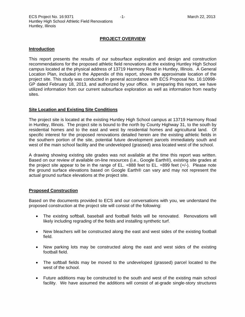
ECS Project No. 16:9371 -1- March 22, 2013 Huntley High School Athletic Field Renovations Huntley, Illinois
PROJECT OVERVIEW Introduction This report presents the results of our subsurface exploration and design and construction recommendations for the proposed athletic field renovations at the existing Huntley High School campus located at the physical address of 13719 Harmony Road in Huntley, Illinois. A General Location Plan, included in the Appendix of this report, shows the approximate location of the project site. This study was conducted in general accordance with ECS Proposal No. 16:10998-GP dated February 18, 2013, and authorized by your office. In preparing this report, we have utilized information from our current subsurface exploration as well as information from nearby sites. Site Location and Existing Site Conditions The project site is located at the existing Huntley High School campus at 13719 Harmony Road in Huntley, Illinois. The project site is bound to the north by County Highway 31, to the south by residential homes and to the east and west by residential homes and agricultural land. Of specific interest for the proposed renovations detailed herein are the existing athletic fields in the southern portion of the site, potential future development parcels immediately south and west of the main school facility and the undeveloped (grassed) area located west of the school. A drawing showing existing site grades was not available at the time this report was written. Based on our review of available on-line resources (i.e., Google Earth®), existing site grades at the project site appear to be in the range of EL. +888 feet to EL. +899 feet (+/-). Please note the ground surface elevations based on Google Earth® can vary and may not represent the actual ground surface elevations at the project site. Proposed Construction Based on the documents provided to ECS and our conversations with you, we understand the proposed construction at the project site will consist of the following:
• The existing softball, baseball and football fields will be renovated. Renovations will likely including regrading of the fields and installing synthetic turf.
• New bleachers will be constructed along the east and west sides of the existing football
field.
• New parking lots may be constructed along the east and west sides of the existing football field.
• The softball fields may be moved to the undeveloped (grassed) parcel located to the
west of the school.
• Future additions may be constructed to the south and west of the existing main school facility. We have assumed the additions will consist of at-grade single-story structures

ECS Project No. 16:9371 -2- March 22, 2013 Huntley High School Athletic Field Renovations Huntley, Illinois
and the finished grades of the proposed structures will approximately match existing finished floor elevations.
Purpose of Exploration and Scope of Work The purpose of this exploration was to evaluate the subsurface conditions at the site and to develop geotechnical engineering recommendations to help guide the design and construction of the project. We accomplished these purposes by performing the following scope of services:
1. Reviewing the geotechnical reports prepared for nearby project sites by ECS; 2. Drilling twenty-nine (29) soil borings to depth of 5 to 20 feet below the existing
site grades throughout the project site, to explore the subsurface soil and groundwater conditions;
3. Performing laboratory tests on representative samples from the borings to
evaluate pertinent engineering properties
4. Analyzing the field and laboratory data from this and previous explorations to develop appropriate geotechnical engineering recommendations; and,
5. Preparing this geotechnical report of our findings and recommendations. The conclusions and recommendations contained in this report are based on the twenty-nine (29) soil borings (designated as B-1 through B-29) conducted at the project site under ECS’ direction. The borings were drilled to depths in the range of 5 to 20 feet below existing site grades. The subsurface exploration included split-spoon soil sampling, standard penetration tests (SPT) and groundwater level observations in the boreholes. The results of the completed soil borings along with a Boring Location Plan are included in the Appendix of this report. The Boring Location Plan was developed from Google Earth® site aerial photograph. The borings were located in the field by an ECS representative and the approximate locations are shown on the Boring Location Plan. Ground surface elevations at the individual boring locations were interpreted based on our review of available on-line resources (i.e., Google Earth®) and may differ from the actual ground surface elevations. Our review of Google Earth® indicates existing site grades may be the range of EL. +888 feet to +899 feet (+/-).

ECS Project No. 16:9371 -3- March 22, 2013 Huntley High School Athletic Field Renovations Huntley, Illinois
EXPLORATION PROCEDURES Subsurface Exploration Procedures The borings were located in the field by an ECS representative using GPS techniques based on the boring location plan provided to us by Wold Architects and Engineers. The driller contacted the Illinois State One-Call Utility System, JULIE, to clear and mark underground utilities in the vicinity of the project site prior to drilling operations. The soil borings were performed with a CME-45 truck-mounted rotary-type auger drill rig, which utilized continuous flight augers to advance the boreholes. Representative soil samples were obtained by means of conventional split-barrel sampling procedures. Samples were typically obtained at 2½-foot intervals in the upper 10 feet and at 5-foot intervals thereafter. In this procedure, a 2-inch O.D., split-barrel sampler is driven into the soil a distance of 18 inches by a 140-pound hammer falling 30 inches. The number of blows required to drive the sampler through a 12-inch interval, after initial setting of 6 inches, is termed the Standard Penetration Test (SPT) or N-value and is indicated for each sample on the boring logs. The SPT value can be used as a qualitative indication of the in-place relative density of cohesionless soils. In a less reliable way, it also indicates the consistency of cohesive soils. This indication is qualitative, since many factors can significantly affect the standard penetration resistance value and prevent a direct correlation between drill crews, drill rigs, drilling procedures, and hammer-rod-sampler assemblies. The drill rig utilized an automatic trip hammer to drive the sampler. Consideration of the effect of the automatic hammer’s efficiency was included in the interpretation of subsurface information for the analyses prepared for this report. A field log of the soils encountered in the borings was maintained by the drill crew. After recovery, each geotechnical soil sample was removed from the sampler and visually classified. Representative portions of each soil sample were then sealed in jars. The soil samples were then brought to our laboratory in Buffalo Grove, Illinois for further visual examination and laboratory testing. After completion of the drilling operations, the boreholes were backfilled with auger cuttings to the existing ground surface. Laboratory Testing Program Representative soil samples were selected and tested in our laboratory to check field classifications and to determine estimate engineering properties. The laboratory testing program included visual classifications, calibrated hand penetrometer unconfined compressive strength testing and moisture content determinations of cohesive soil samples. Each soil sample was classified on the basis of texture and plasticity in accordance with the Unified Soil Classification System. The group symbols for each soil type are indicated in parentheses following the soil descriptions on the boring logs. A brief explanation of the Unified System is included with this report. The various soil types were grouped into the major zones noted on the boring logs. The stratification lines designating the interfaces between earth materials on the boring logs and profiles are approximate; in situ, the transitions may be gradual.

ECS Project No. 16:9371 -4- March 22, 2013 Huntley High School Athletic Field Renovations Huntley, Illinois
The unconfined compressive strength (Qp) of relatively cohesive clay soil samples was estimated with the use of a calibrated hand penetrometer. In the hand penetrometer test, the unconfined compressive strength of a soil sample is estimated, to a maximum of 4½ tons per square foot (tsf) by measuring the resistance of a soil sample to penetration of a small, calibrated spring-loaded cylinder. The soil samples will be retained in our laboratory for a period of 60 days, after which, they will be discarded unless other instructions are received as to their disposal.
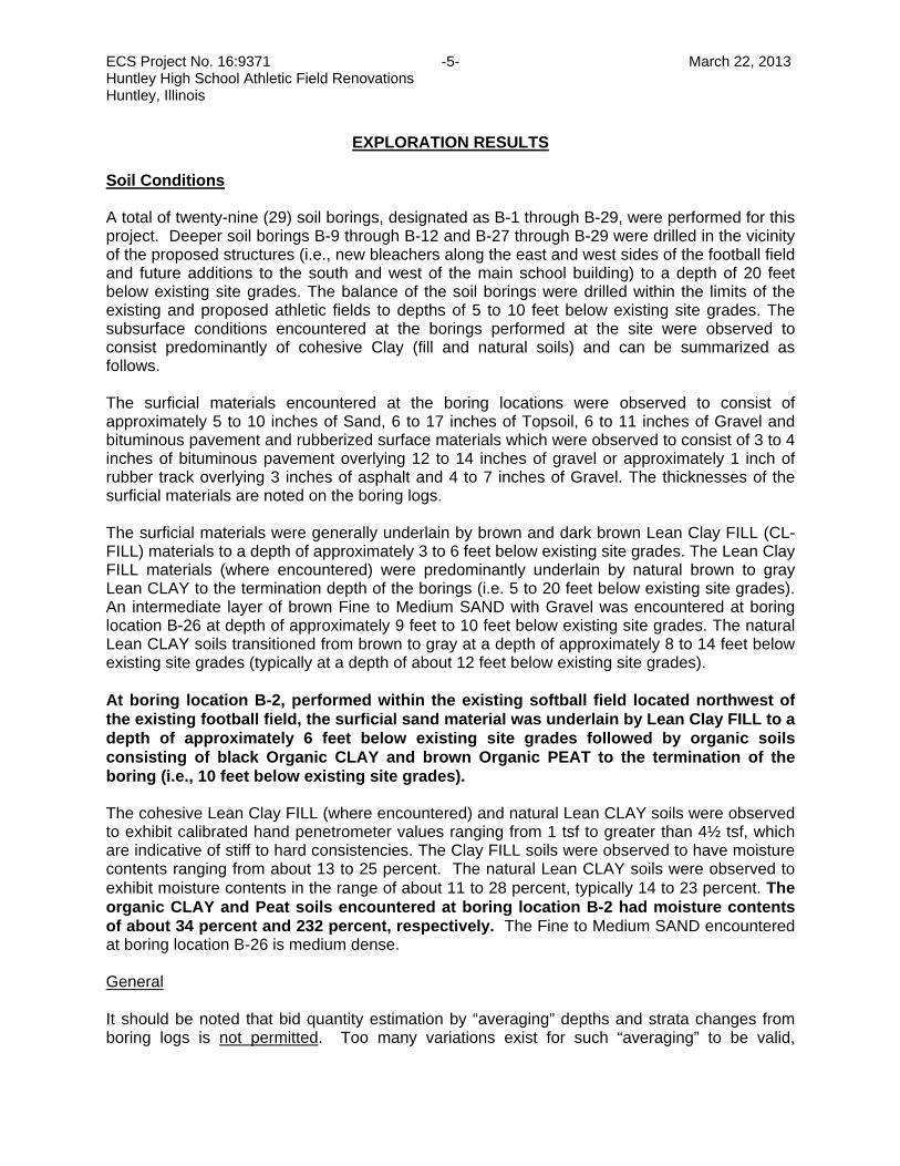
ECS Project No. 16:9371 -5- March 22, 2013 Huntley High School Athletic Field Renovations Huntley, Illinois
EXPLORATION RESULTS Soil Conditions A total of twenty-nine (29) soil borings, designated as B-1 through B-29, were performed for this project. Deeper soil borings B-9 through B-12 and B-27 through B-29 were drilled in the vicinity of the proposed structures (i.e., new bleachers along the east and west sides of the football field and future additions to the south and west of the main school building) to a depth of 20 feet below existing site grades. The balance of the soil borings were drilled within the limits of the existing and proposed athletic fields to depths of 5 to 10 feet below existing site grades. The subsurface conditions encountered at the borings performed at the site were observed to consist predominantly of cohesive Clay (fill and natural soils) and can be summarized as follows. The surficial materials encountered at the boring locations were observed to consist of approximately 5 to 10 inches of Sand, 6 to 17 inches of Topsoil, 6 to 11 inches of Gravel and bituminous pavement and rubberized surface materials which were observed to consist of 3 to 4 inches of bituminous pavement overlying 12 to 14 inches of gravel or approximately 1 inch of rubber track overlying 3 inches of asphalt and 4 to 7 inches of Gravel. The thicknesses of the surficial materials are noted on the boring logs. The surficial materials were generally underlain by brown and dark brown Lean Clay FILL (CL- FILL) materials to a depth of approximately 3 to 6 feet below existing site grades. The Lean Clay FILL materials (where encountered) were predominantly underlain by natural brown to gray Lean CLAY to the termination depth of the borings (i.e. 5 to 20 feet below existing site grades). An intermediate layer of brown Fine to Medium SAND with Gravel was encountered at boring location B-26 at depth of approximately 9 feet to 10 feet below existing site grades. The natural Lean CLAY soils transitioned from brown to gray at a depth of approximately 8 to 14 feet below existing site grades (typically at a depth of about 12 feet below existing site grades). At boring location B-2, performed within the existing softball field located northwest of the existing football field, the surficial sand material was underlain by Lean Clay FILL to a depth of approximately 6 feet below existing site grades followed by organic soils consisting of black Organic CLAY and brown Organic PEAT to the termination of the boring (i.e., 10 feet below existing site grades). The cohesive Lean Clay FILL (where encountered) and natural Lean CLAY soils were observed to exhibit calibrated hand penetrometer values ranging from 1 tsf to greater than 4½ tsf, which are indicative of stiff to hard consistencies. The Clay FILL soils were observed to have moisture contents ranging from about 13 to 25 percent. The natural Lean CLAY soils were observed to exhibit moisture contents in the range of about 11 to 28 percent, typically 14 to 23 percent. The organic CLAY and Peat soils encountered at boring location B-2 had moisture contents of about 34 percent and 232 percent, respectively. The Fine to Medium SAND encountered at boring location B-26 is medium dense. General It should be noted that bid quantity estimation by “averaging” depths and strata changes from boring logs is not permitted. Too many variations exist for such “averaging” to be valid,

ECS Project No. 16:9371 -6- March 22, 2013 Huntley High School Athletic Field Renovations Huntley, Illinois
particularly in the surficial material thicknesses, fill depths, soil types and condition, depth, and groundwater conditions. A different scope of professional services would be required to obtain subsurface information needed for land purchase considerations and earthwork bid preparation. This scope could include additional borings and possibly test pits. Even with this additional information, contingencies should always be carried in construction budgets or land purchase agreements to cover variations in subsurface conditions. Soil borings cannot present the same full-scale view that is obtained during complete site grading, excavation or other aspects of earthwork construction. Groundwater Observations Observations for groundwater were made during sampling and upon completion of the drilling operations at the boring locations. In auger drilling operations, water is not introduced into the boreholes, and the groundwater position can often be obtained by observing water flowing into or out of the boreholes. Furthermore, visual observation of the soil samples retrieved during the auger drilling exploration can often be used in evaluating the groundwater conditions. Groundwater was encountered at boring locations B-1, B-12, B-20, B-26 and B-28 during and after drilling at a depth of approximately 1 foot to 13½ feet below existing site grades. Groundwater was not encountered at the remaining boring locations during and upon completion of drilling. In predominantly cohesive soils, groundwater can take a longer time (i.e., several days or a few weeks) to stabilize in the borehole. Glacial till soils in the Midwest frequently oxidize from gray to brown above the level at which the soil remains saturated. The long-term groundwater level is often interpreted to be near this zone of color change. Based on the results of this exploration and soil color change, the static long-term groundwater level is estimated to be located at a depth of approximately 8 to 12 feet below existing site grades. The very shallow groundwater encountered at boring location B-28 in gravel base layer is indicative of perched water condition. Perched water occurs as rainfall or overland drainage that has infiltrated the ground surface collects, or becomes perched, on layers of less permeable soil such as clays and trapped in granular or permeable layers such as gravel base as it percolates downward, and is typically a transient condition associated with recent rainfall. The highest groundwater observations are normally encountered in late winter and early spring and our current groundwater observations are not expected to be at the seasonal maximum water table. It should be noted that the groundwater level can vary based on precipitation, evaporation, surface run-off and other factors not immediately apparent at the time of this exploration. Surface water runoff will be a factor during general construction, and steps should be taken during construction to control surface water runoff and to remove water that may accumulate in the proposed excavations as well as floor slab and pavement areas.

ECS Project No. 16:9371 -7- March 22, 2013 Huntley High School Athletic Field Renovations Huntley, Illinois
ANALYSIS AND RECOMMENDATIONS Overview The conclusions and recommendations presented in this report should be incorporated in the design and construction of the project to reduce possible soil and/or foundation related problems. The following recommendations have been developed on the basis of the previously described project characteristics and subsurface conditions encountered at the project site. If there are any changes to the project characteristics or if different subsurface conditions are encountered during construction, ECS Midwest, LLC should be consulted so that the recommendations of this report can be reviewed and modified, if necessary. The following sections present specific recommendations with regard to the design of the proposed buildings, exterior pavements and athletic fields. These include recommendations with regard to subgrade preparation and earthwork, fill placement, building foundations, floor slab design, pavement design, athletic fields and construction dewatering. Discussion of the factors affecting the building foundations for the proposed construction, as well as additional recommendations regarding design and construction at the project site are included below. We recommend that ECS review the final design and specifications to check that the earthwork and foundation recommendations presented in this report have been properly interpreted and implemented in the design and specifications. Subgrade Preparation and Earthwork Operations The finished grades of the proposed parking areas and new athletic field and finished floor elevation of the proposed future additions are anticipated to match the existing site grades. If our assumption for the final grade is incorrect, or if existing grades will be raised, especially in the area where organic soils are present (i.e., boring location B-2) please contact ECS so we can review (and revise if appropriate) our recommendations for subgrade preparation discussed below. Initial subgrade preparation for the new synthetic turf field, exterior pavements and building pads should consist of complete removal of existing vegetation, surficial topsoil, bituminous pavements and other deleterious organic or refuse material. Based on the results of the borings, stripping to depths in the range of ½ to 1½ foot is anticipated to remove vegetation, surficial topsoil and bituminous pavements within the area of the proposed development. The existing topsoil can be stockpiled on site for later re-use in the landscaping areas. The existing clean surficial sand and gravel and gravel base materials can be reused as new fill provided they are free of organic matter and deleterious materials, not mixed with fines (i.e., clays) and approved by the project geotechnical engineer of record. Once the surficial materials have been removed, the limits of the synthetic turf field, parking lots, drive lanes and building pads should be excavated to the design subgrade elevation. ECS does not recommend the slab and pavement subgrades remain exposed to the elements or construction traffic for a prolonged period of time as the subgrade may be disturbed and/or softened. If the slab and/or pavement section is not planned to be constructed within a few days after exposing the final design subgrade, consideration should be given to leaving the subgrade approximately 1 foot above the final design subgrade to help prevent softening of the design subgrade soils (if feasible).

ECS Project No. 16:9371 -8- March 22, 2013 Huntley High School Athletic Field Renovations Huntley, Illinois
Based on the results of our subsurface exploration we anticipate Lean Clay FILL and natural Lean CLAY will be encountered at the artificial athletic turf, pavement and slab subgrade elevations. Based on our observation of the existing lean clay fill and results of laboratory testing, the existing stable lean clay fill materials can remain in place beneath synthetic turf and pavements provided the subgrades pass a proofroll and evaluated/approved by the project Geotechnical Engineer of Record. We recommend an ECS representative be on site to observe and evaluate the exposed subgrade during construction operations. Buried Organic Soils Buried organic soils (i.e., black Organic CLAY and brown Organic PEAT) was encountered at a depth of approximately 6 feet below existing site grades at boring location B-2. The organic soils were overlain by very stiff Lean Clay FILL. We understand new pavements will be constructed in this area. For parking lot pavements, the existing lean clay fill and buried organic soils can remain provided the lean clay fill subgrade passes a proofroll and the owner can accept some risk of premature deterioration of the pavements and long term maintenance issues related to consolidation of the organic soils. We recommend the existing grades be maintained and no significant fill (i.e. greater than 2 feet of new fill) be placed in the area where compressible organic soils are present. Placing significant fill on top of the compressible organic soils can result in settlement/compression of several inches due to weight of fill and traffic loads. Unless the buried organic soils are completely removed, we recommend flexible pavement as opposed to rigid pavement be considered. Flexible pavements should be more tolerant to long term consolidation of the organic soils and generally require less costly repairs. The organic soils are not suitable to support structures. To better delineate the limits of the buried organic soils, we recommend that test pits be performed prior to mass grading activities and/or prior to bidding. Proofrolling Upon stripping to the desired subgrade elevations and prior to placement of new fills to raise and reach final subgrades, the exposed subgrades should be observed by the Geotechnical Engineer of Record or his authorized representative and be proofrolled. Proofrolling using a loaded dump truck, having an axle weight of at least 10 tons, can be used to aid in identifying localized soft or unsuitable material which should be removed. Prior to proofrolling, we recommend the exposed existing fill subgrades be densified to the extent practical with heavy-duty vibratory compaction equipment. The densification and proofrolling of the exposed subgrades should be performed under the observation of the Geotechnical Engineer of Record or his authorized representative. If soft or yielding soils are observed during the densification/proofroll, the soft or yielding soils should be undercut a maximum of 2 feet and replaced with compacted and engineered fill to the design subgrade in accordance with the Fill Placement section of this report. To help limit the volume of soil removed as a result of the proofrolling observations, we recommend that soft or yielding soils be evaluated in approximately 6-inch intervals. That is to say, if soft or yielding soils are identified, the contractor should remove 6 inches of material in the subject area and then proofroll/evaluate the undercut subgrade. This may potentially limit the need to remove 2 feet of soil at all locations where soft or yielding soils are identified. A DCP (dynamic cone penetrometer) can also be used in conjunction with proofrolling to establish appropriate depths for remedial action.

ECS Project No. 16:9371 -9- March 22, 2013 Huntley High School Athletic Field Renovations Huntley, Illinois
Subgrade Preparation – Building Foundations and Slabs-on-Grade For building foundations, we do not recommend the footings and slabs-on-grade bear on or above existing fill materials. Existing fill should be completely removed from proposed structure areas and to a distance not less than 5 feet beyond the perimeter. The resulting excavation should be monitored by the Geotechnical Engineer of Record to verify that proper and not excessive undercutting has been performed. The undercut excavations should be backfilled in strict accordance with the Fill Placement section of this report. Subgrade Preparation - General We recommend contingencies should be included in construction budgets to cover the cost of removal and replacement of unsuitable and soft/loose soils and existing fill within structure areas. The earthwork operations and subgrade preparation should be monitored by a qualified geotechnical field engineer or his field representative to make sure unsuitable soils and other deleterious material is stripped. All underground utilities should be positively located, properly protected and supported. Underground utilities within the proposed project areas should be relocated or removed and backfilled with engineered fill. Abandoned utilities should be removed or grouted in place. The contractor should be responsible for underpinning or other adequate support during excavations adjacent to existing utilities, sidewalks and foundations. The contractor shall control surface water runoff and to remove any water from precipitation that may accumulate in the subgrade areas, especially during the wet season. When wet and subjected to construction traffic, softening and disturbance of the exposed clay subgrade soils may occur. Construction traffic should be limited when the subgrade is wet. During final preparation of synthetic turf field, pavement and building pad subgrades, a smooth drum roller should be used to provide a flat surface and help provide for better drainage to reduce the negative impact of rain events. We also recommend crowning the subgrade to provide positive drainage off the synthetic turf field, new ball fields, parking lot and building pad subgrades. Care should be exercised during subgrade preparation (i.e. compaction operations) to reduce instability of the subgrade soils and observations should be made during earthwork operations to determine whether the weight of the construction equipment is negatively impacting the site soils. Minimizing disturbance to the exposed subgrade is important for proper construction of the synthetic turf field, parking lot, slab and foundation systems. The need for and most appropriate type of stabilization required will be dependent upon soil, groundwater and weather conditions, as well as, the construction schedule and methods of construction that will be used. In general, scarifying, drying and recompacting moderately unstable soil areas is expected to be the most economical means of improving the poor and high moisture content soils prior to final preparation of building pad and pavement subgrades. The best period for air drying soils typically occurs in dry times of the year (i.e., summer), and the warm weather experienced in the summer months usually is more conducive to dry site conditions. Alternatives for subgrade stabilization could also include undercutting and replacing unsuitable soils with engineered fill as recommended herein. If earthwork operations will be performed in normally wet times of the year (i.e., spring/fall), soil modification such as lime/Portland cement stabilization may be appropriate. The surface of the

ECS Project No. 16:9371 -10- March 22, 2013 Huntley High School Athletic Field Renovations Huntley, Illinois
soil to be lime/cement stabilized should be scarified prior to applying the lime/cement to achieve uniform mixing throughout the soil matrix. The specialty contractor is responsible for the means and methods of lime/cement stabilization process, and should provide at the conclusion a stable subgrade meeting the project requirements. Lime stabilization should be performed such that problems related to re-hydration of the lime do not occur. Lime stabilized soils should be compacted to at least 95% of the maximum dry density obtained in accordance with the modified Proctor method, ASTM D 1557. Excavations should comply with the requirements of OSHA 29CFR, Part 1926, Subpart P, "Excavations" and its appendices, as well as other applicable codes. This document states that the contractor is solely responsible for the design and construction of stable, temporary excavations. The excavations should not only be in accordance with current OSHA excavation and trench safety standards but also with applicable local, state, and federal regulations. The contractor should shore, slope or bench the excavation sides when appropriate. If problems are encountered during the earthwork operations, or if site conditions deviate from those encountered during our subsurface exploration, ECS should be notified immediately. We recommend that the project geotechnical engineer or his representative should be on site to monitor stripping and site preparation operations and observe that unsuitable soils have been satisfactorily removed and observe the proofrolling of the subgrades. Fill Placement All fills should consist of an approved material, free of organic matter and debris, particles greater than 3-inches and have a Liquid Limit and Plasticity Index less than 40 and 15, respectively. Unacceptable fill materials include topsoil and organic materials (OH, OL), high plasticity silts and clays (CH, MH), and low-plasticity silts (ML). Under no circumstances should high plasticity soils be used as fill material in proposed structural areas or close to site slopes. The stripped existing surficial sand and gravel materials and gravel base materials beneath the pavement can be stockpiled and reused as engineered fill provided they are clean, free of organic matter and deleterious materials, not mixed with fines (i.e., clays) and approved by the project Geotechnical Engineer of Record. We believe the excavated on site lean clay (fill and natural) soils should be suitable for re-use as new fill. We recommend on-site and off-site soils to be considered as new engineered fill should be evaluated and approved by the project Geotechnical Engineer of Record prior to or during construction operations. The on-site soils if re-use for fill will require moisture content adjustments, such as the application of discing or other drying/wetting techniques prior to their use as compacted fill (termed manipulation). The planning of earthwork operations should recognize and account for increased costs associated with manipulation of the on-site materials considered for reuse as compacted fill. Fill materials should be placed in lifts not exceeding 8-inches in loose thickness and moisture conditioned to within ±2 percentage points of the optimum moisture content. Soil bridging lifts should not be used since intolerable settlement of overlying structures will likely occur. Controlled fill soils should be compacted to a minimum of 95% of the maximum dry density obtained in accordance with ASTM Specification D 1557, Modified Proctor Method. The expanded footprint of the proposed synthetic turf field, pavement, building pad and fill areas should be well defined, including the limits of the fill zones at the time of fill placement. Grade

ECS Project No. 16:9371 -11- March 22, 2013 Huntley High School Athletic Field Renovations Huntley, Illinois
control should be maintained throughout the fill placement operations. All fill operations should be observed on a full-time basis by a qualified soil technician to determine that the specified compaction requirements are being met. A minimum of one compaction test per 2,500 square foot area should be tested in each lift placed. Within trench or other localized excavations, one test for each 50 linear feet of each lift of fill shall be performed. The elevation and location of the tests should be clearly identified at the time of fill placement. Compaction equipment suitable to the soil type used as fill should be used to compact the fill material. Theoretically, any equipment type can be used as long as the required density is achieved; however, the standard of practice typically dictates that a vibratory roller be utilized for compaction of granular soils and a sheepsfoot roller be utilized for compaction of cohesive soils. In addition, a steel drum roller is typically most efficient for compacting and sealing the surface soils. All areas receiving fill should be graded to facilitate positive drainage away from the building pad and pavement areas. It should be noted that prior to the commencement of fill operations and/or utilization of off-site borrow materials, the Geotechnical Engineer of Record should be provided with representative samples to determine the material’s suitability for use in a controlled compacted fill and to develop moisture-density relationships. In order to expedite the earthwork operations, if off-site borrow materials are required, it is recommended they consist of suitable fill materials in accordance with the recommendations previously outlined in this section. Fill materials should not be placed on frozen soils or frost-heaved soils and/or soils that have been recently subjected to precipitation. All frozen soils should be removed prior to continuation of fill operations. Borrow fill materials, if required, should not contain frozen materials at the time of placement. All frost-heaved soils should be removed prior to placement of controlled, compacted fill, granular subbase materials, foundation or slab concrete, and asphalt pavement materials. Open-Graded Fill Materials ECS understands site conditions or project constraints occur where the use of crushed CA-7 or CA-1 (3-inch rock) is recommended by the Contractor as substitution for engineered fill. Upon approval by ECS, CA-7 or CA-1 may only be used if properly documented and witnessed by an experienced ECS Geotechnical engineer or qualified ECS representative. The installation must be observed by an ECS representative full-time during placement operations. ECS encourages the placement of a geotextile fabric as a separator between the open-graded material and the native subgrade. This geotextile material reduces the potential for intermixing of the subgrade soils with the open-graded aggregate and potential settlement. Pea gravel should not be used as engineered fill. If open-graded CA-7 or CA-1 (3-inch rock) is to be considered for use as backfill, the CA-7 and CA-1 should be placed in accordance with the guidelines described herein. We recommend the open-graded granular fill materials should be placed in lifts not exceeding 8 inches in loose thickness for CA-7 and 12 inches in loose thickness for CA-1. Each lift should be densified or compacted to the extent practical. The open-graded aggregates can not be tested using conventional density testing methods and therefore do not meet the definition of engineered fill as described elsewhere in this report.
ECS Project No. 16:9371 -12- March 22, 2013 Huntley High School Athletic Field Renovations Huntley, Illinois
Proper placement of the open-graded material is typically achieved by using a smooth drum vibratory roller, “hoe pac” or backhoe bucket techniques wherein the operator applies energy to the open-graded aggregate until the stone “closes up” and interlock is observed. Due to the inability to utilize conventional compaction testing methods; an ECS engineer or qualified ECS representative should observe the material placed in lifts less than 8 to 12 inches in loose thickness, that the material is “closed up” (interlocked and stable), and under significant load no further densification or shifting occurs. Oversized fragments (greater than 3 inches in diameter) should be rejected and pulled from the fill. We recommend applying a sufficient number of passes with heavy vibratory steel wheel roller (minimum weight of 10,000 pounds), “hoe pac” or a sufficient number of impacts with a backhoe bucket to achieve interlock and a stable material. If deemed necessary by ECS, more energy may need to be applied after the contractor’s selected method of compaction. A “choking layer” at least 8 inches in thickness of CA-6 or similar materials (including a geotextile separator fabric as described above) should be placed on top of the 3-inch rock, at the final subgrade elevation. Foundation Recommendations Borings B-9, B-10, B-11, B-12, B-27, B-28 and B-29 were performed in the vicinity of the proposed new bleachers and building additions. The borings encountered undocumented Lean Clay FILL (CL- FILL) materials to a depth of approximately 3 to 6 feet below existing site grades underlain by natural Lean CLAY soils. Based on the subsurface conditions encountered at the project site, results of laboratory testing and our understanding of the proposed construction, the proposed structures can be supported on shallow foundations bearing on competent natural soils (Lean CLAY) or new engineered fill overlying competent natural soils. We do not recommend the footings bear on or above existing fill materials. Existing fill materials should be completely removed beneath all proposed foundations such that the footings bear on competent natural soils or on engineered fill used to replace unsuitable existing fill materials. A shallow foundation system bearing on competent natural soils (Lean CLAY) or new engineered fill overlying competent natural soils can be designed for a net allowable bearing pressure of 3,000 psf. The net allowable soil bearing pressure refers to that pressure which may be transmitted to the foundation bearing soils in excess of the final minimum surrounding overburden pressure. Competent soils can be identified on the boring log as natural cohesive soils having unconfined compressive strengths 1½ tsf or greater. If you do not elect to completely remove and replace the existing undocumented fill, the shallow foundation excavations will have to extend completely through the existing fill to encounter natural lean clay soil. The corresponding depths of foundation over-excavation may range from about 3 to 6 feet based the conditions indicated by the borings. Soft/unsuitable material may be present at or below the typical bearing elevation of foundations. We recommend that visual soil classification by an ECS representative supplemented with hand auger probes, in-situ vane shear testing, and/or DCP testing be performed to a depth below the foundation subgrade equivalent to ½ the footing width (i.e., ½ B), or a minimum of 3 feet below each isolated column footing and to at least 2 feet below continuous footings. Visual soil classification supplemented with hand auger probes, in-situ vane shear testing, and/or DCP testing should be performed at each column footing and at approximately 20-foot intervals along continuous footings to verify the suitability of the soils to support the recommended maximum net allowable bearing pressure.
ECS Project No. 16:9371 -13- March 22, 2013 Huntley High School Athletic Field Renovations Huntley, Illinois
As mentioned above, the footing excavations should be extended until suitable natural bearing soils are encountered or the loose/unstable soils should be removed beneath the base of the footing and replaced with new engineered fill. We recommend granular engineered fill be used to backfill undercuts beneath the footings. The engineered fill should be compacted to a minimum of 95% of the maximum dry density in accordance with modified Proctor method, ASTM D 1557. The zone of the engineered fill placed below the foundations should extend 1 foot beyond the outside edges of the footings and from that point, outward laterally 1 foot for every 2 feet of fill thickness below the footing. We recommend that the excavation/backfill of foundations be monitored full-time by an ECS geotechnical engineer or his representative to verify that the soil bearing pressure is consistent with the boring information obtained during the geotechnical exploration. In areas where individual footings are founded at different elevations, it is important to provide a minimum slope of 1H:1V between the bottom edge of each foundation at their closest point. New footings adjacent to existing foundations should bear at same elevation as existing foundations. Care must be taken during excavation for new footings to prevent undermining of adjacent existing construction. Any excavation below the adjacent existing foundations, slabs, pavement, sidewalks and underground utilities should consider appropriate preventative measures, such as underpinning, to avoid undermining or loss of materials from beneath foundations, structures and pavements. Excavations should not extend below adjacent foundations unless underpinning or other forms of intermediate support are provided. Frost Depth and Minimum Footing Dimensions Footings should be placed at a depth to provide adequate frost cover protection. For this region, we recommend the exterior footings and footings beneath unheated areas be placed at a minimum depth of 3½ feet below finished grade. Interior footings in heated areas can be placed at a minimum of 2 feet below grade provided suitable soils are encountered and that the foundations will not be subjected to freezing weather either during or after construction. To reduce the potential for foundation bearing failure and excessive settlement due to local shear or "punching" action, we recommend continuous footings have a minimum width of 18 inches and that isolated column footings have a minimum lateral dimension of 30 inches. Foundation Settlement Settlement of individual footings, designed in accordance with our recommendations presented in this report, is expected to be small and within tolerable limits for the proposed anticipated building additions. For footings placed on suitable soils or properly compacted engineered fill, maximum total settlement is expected to be in the range of 1 inch or less. Maximum differential settlement between adjacent columns is expected to be one-half the total settlement. These settlement values are based on our engineering experience and the anticipated structural loading, and are to help guide the structural engineer with his design. Floor Slab Design We do not recommend supporting new concrete slabs-on-grade directly on existing undocumented fill. If the owner is willing to accept some risk of slab distress, partial undercutting may be performed in new slab-on-grade areas as described in the Subgrade
ECS Project No. 16:9371 -14- March 22, 2013 Huntley High School Athletic Field Renovations Huntley, Illinois
Preparation and Earthwork Operations. Otherwise, the existing fill should be completely removed and replaced with new engineered fill. The slab thickness can be determined utilizing an assumed modulus of subgrade reaction of 100 pounds per cubic inch (pci). We recommend the slab be designed with a minimum thickness of 5 inches. We recommend that floor slabs be underlain by a minimum of 6 inches of granular material having a maximum aggregate size of 1½ inches and no more than 2% soil fines passing the No. 200 sieve. This granular layer will facilitate the fine grading of the subgrade and help prevent the rise of water through the floor slab. Prior to placing the granular material, the floor subgrade should be free of standing water, mud, and frozen soil. Before the placement of concrete, a vapor barrier may be placed on top of the granular material to provide additional moisture protection. Welded-wire mesh reinforcement should be placed in the upper half of the floor slab and attention should be given to the surface curing of the slab in order to minimize uneven drying of the slab and associated cracking and/or slab curling. The use of a blotter or cushion layer above the vapor retarder can also be considered for project specific reasons. Please refer to ACI 302.1R04 Guide for Concrete Floor and Slab Construction and ASTM E 1643 Standard Practice for Installation of Water Vapor Retarders Used in Contact with Earth or Granular Fill Under Concrete Slabs for additional guidance on this issue. We recommend that floor slabs be isolated from the foundations so differential settlement of the structure will not induce shear stresses on the floor slab. For maximum effectiveness, temperature and shrinkage reinforcements in slabs on ground should be positioned in the upper third of the slab thickness. The Wire Reinforcement Institute recommends the mesh reinforcement be placed 2 inches below the slab surface or upper one-third of slab thickness, whichever is closer to the surface. Adequate construction joints, contraction joints and isolation joints should also be provided in the slab to reduce the impacts of cracking and shrinkage. Please refer to ACI 302.1R04 Guide for Concrete Floor and Slab Construction for additional information regarding concrete slab joint design. Underslab Sub-Drainage Based on the groundwater levels observed during the subsurface exploration, we do not anticipate a significant volume of water will persist at the slab subgrade elevation of the proposed building additions. It should be noted, however, that surface water runoff and limited groundwater seepage may accumulate at the slab subgrade. As such, we recommend that positive drainage be implemented around the perimeter of the proposed additions to help reduce the potential for water accumulation beneath the floor slab and foundation elements, which could potentially weaken the bearing soils. Exterior Pavement Recommendations We anticipate the proposed parking lot will be asphaltic concrete and will generally be utilized for light to heavy duty traffic. We recommend that the pavement subgrade be prepared in accordance with the Subgrade Preparation and Earthwork Operations section of this report. As mentioned earlier, in pavement areas where buried organic soils are present (i.e., boring location B-2), we recommend flexible pavement as opposed to rigid pavement be considered.
ECS Project No. 16:9371 -15- March 22, 2013 Huntley High School Athletic Field Renovations Huntley, Illinois
Once the subgrade has been properly prepared, we recommend the following minimum pavement sections for the proposed development. Table 1: Pavement Section Recommendations
Compacted Material Thicknesses (Inches)
Pavement Material Flexible Pavement
(Light Duty)
Flexible Pavement
(Heavy Duty)
Rigid Pavement
(Light Duty)
Rigid Pavement
(Heavy Duty)
Portland Cement Concrete
-- -- 5 6
Surface Course Asphalt 1½ 1½ -- --
Base Course Asphalt 2 3 -- --
Crushed Granular Subbase
(CA-6) 8 12 6 6
Total Pavement Section Thickness 11½ 16½ 11 12
Where pavement areas are underlain by buried organic soils, we recommend that you consider installing a medium to heavy weight geotextile (e.g. Mirafi HP 370 or HP 570) over the exposed final subgrade prior to placing the recommended crushed granular base. Otherwise, the recommended thickness of crushed granular subbase should be increased by 4 inches to help reduce the potential for significant premature pavement distress. All pavement materials and construction, with the exception of the modified Proctor compaction specification, should be in accordance with the Guidelines for AASHTO Pavement Design. The pavement sections specified in the table above are general pavement recommendations based on the anticipated usage at the project site. The heavy duty pavement section should be utilized in locations where school bus and truck traffic (i.e., delivery lanes, loading dock, etc.) is anticipated and frequent traffic such as entrance and exit drives. The light duty pavement section can be used parking lot areas for standard automobile traffic. It should also be noted that the pavement sections specified in the table above were developed for the anticipated in-service traffic conditions only and do not provide an allowance for construction traffic conditions. Therefore, if pavements will be constructed early during site development to accommodate construction traffic, consideration should be given to the construction of designated haul roads, where thickened pavement sections can be provided to help accommodate the construction traffic, as well as the future in-service traffic. ECS can provide additional design assistance with pavement sections for haul roads upon request. We recommend the crushed granular base course should be compacted to at least 95 percent of the maximum dry density obtained in accordance with ASTM D 1557, modified Proctor method. During asphalt pavement construction, the wearing and leveling course should be
ECS Project No. 16:9371 -16- March 22, 2013 Huntley High School Athletic Field Renovations Huntley, Illinois
compacted to a minimum of 93 percent of the theoretical density value. Prior to placing the granular material, the pavement subgrade soil should be properly compacted, proofrolled, and free of standing water, mud, and frozen soil. The pavements should be designed and constructed with adequate surface and subsurface drainage. Where standing water develops, either on the pavement surface or within the base course layer, softening of the subgrade and other problems related to the premature deterioration of the pavement can be expected. Furthermore, good drainage should minimize the possibility of the subgrade materials beneath the pavement becoming saturated over a long period of time. Infiltration and subterranean water are the two sources of water that should be considered in the pavement design for the project. Infiltration is surface water that enters the pavement through the joints, pores, cracks in the pavement and through shoulders and adjacent areas pavements as a result of precipitation. Subterranean water is a source of water from a high water table on the site. The long term groundwater level on the site is estimated to be located at a depth of approximately 8 to 12 feet below existing site grades. Therefore, infiltration is the most important source of water to be considered for this project. Large, front loading trash dumpsters frequently impose concentrated front-wheel loads on pavements during loading. This type of loading typically results in rutting of the pavement and ultimately pavement failures. Therefore, we recommend that the pavement in trash pickup areas consist of the heavy duty rigid pavement section in Table 1. It should be noted that the pavement should be comprised of air-entrained Portland cement concrete with a minimum compressive strength of 4,000 psi and a minimum flexural strength of 650 psi. Adequate construction joints, contraction joints and isolation joints should be provided in the areas of rigid pavement to reduce the impacts of cracking and shrinkage. Please refer to ACI 330R-92 Guide for Design of Concrete Parking Lots. The Guide recommends an appropriate spacing strategy for the anticipated loads and pavement thickness. It has been our experience that joint spacing closer to the minimum values results in a pavement with less cracking and better long term performance. Pavement Maintenance Regular maintenance and occasional repairs should be implemented to help keep pavements in a serviceable condition. In addition, to help minimize water infiltration to the pavement section and within the base course layer resulting in softening of the subgrade and deterioration of the pavement, we recommend the timely sealing of joints and cracks using elastomeric caulk/sealant in existing pavement. We recommend exterior pavements should be reviewed for distress/cracks twice a year, once in the spring and once in the fall. The Owner should anticipate additional long term pavement maintenance in pavement areas where buried organic soils are present (in the vicinity of boring location B-2), unless the buried organic soils are completely removed and replaced with new engineered fill, placed and compacted as recommended herein.

ECS Project No. 16:9371 -17- March 22, 2013 Huntley High School Athletic Field Renovations Huntley, Illinois
Artificial Synthetic Turf Installation Recommendations The new synthetic field should be installed and constructed in accordance with manufacturer’s specifications and guidelines including the required base and drainage material. The soil conditions encountered at the project site consist predominantly of cohesive clay soils which are considered relatively impermeable. We recommend the artificial synthetic turf field should be designed with an underdrainage system connected to storm manholes or other suitable outlets. Based on our experience with similar artificial athletic field construction, open-graded drainage material for underground detention can be placed beneath the synthetic turf field. Collector pipes or drain tiles should be included to facilitate the removal of water beneath the athletic field. We recommend the placement of geotextile fabric to act as a separator between the open-graded granular material and synthetic turf field subbase to prevent fines from mitigating into the open-graded drainage granular layer. If CA-1 is used as the drainage layer media, we recommend a minimum 4-inch lift of CA-6 be placed to choke off the CA-1. We also recommend crowning/sloping the clay subgrade to provide positive drainage off the athletic field subgrades. We recommend subgrades should be crowned, or sloped, a minimum of 1% to promote subsurface water flow across the clay subgrades. Drains or other outlets should be provided at the low points to remove water from the subgrade.

ECS Project No. 16:9371 -18- March 22, 2013 Huntley High School Athletic Field Renovations Huntley, Illinois
PROJECT CONSTRUCTION RECOMMENDATIONS General Construction Considerations We recommend that the subgrade preparation, installation of the foundations, and construction of synthetic turf field, pavements and slabs-on-grade be monitored by an ECS geotechnical engineer or his representative. Methods of verification and identification such as proofrolling, vane shear/DCP testing and hand auger probe holes will be necessary to further evaluate the subgrade soils and identify unsuitable soils. The contractor should be prepared to over-excavate footing and slab-on-grade excavations at isolated locations (as necessary). We recommend that excavations of new foundations be monitored on a full-time basis by an ECS geotechnical engineer or his representative to verify that the soil bearing pressure and the exposed subgrade materials will be suitable for the proposed structure and are consistent with the boring log information obtained during this geotechnical exploration. We would be pleased to provide these services. Care must be taken during excavation for new footings to prevent undermining of adjacent existing construction. Any excavation below the adjacent existing foundations, slabs, pavement, sidewalks and underground utilities should consider appropriate preventative measures, such as underpinning, to avoid undermining or loss of materials from beneath foundations, structures and pavements. Excavations should not extend below adjacent foundations unless underpinning or other forms of intermediate support are provided. Foundation Subgrade Preparation If the existing fill is not completely removed from proposed structure areas and the Owner elects to only extend foundation excavations through the fill to suitable bearing soils, we recommend that hand auger probes and/or vane shear/DCP testing be performed to a depth below the foundation subgrade equivalent to ½ the footing width (i.e., ½ B), or a minimum of 3 feet below each isolated column footing and to at least 2 feet below continuous footings. Hand auger probes and/or DCP tests should be performed at each column footing and at approximately 20-foot intervals along continuous footings to verify the suitability of the soils to support the recommended maximum net allowable bearing pressure. All engineered fill placed in structure areas or within foundation undercut excavations should be should be compacted to a minimum of 95 % of the maximum dry density in accordance with modified Proctor method, ASTM D 1557. The zone of the engineered fill placed below the foundations should extend 1 foot beyond the outside edges of the footings and from that point, outward laterally 1 foot for every 2 feet of fill thickness below the footing. As discussed in the Foundation Recommendations section of this report, we recommend granular engineered fill be used minimized the effects of self-weight consolidation and to maintain maximum foundation settlement at about 1 inch. We recommend that the excavation/backfill of building foundations be monitored full-time by an ECS Geotechnical Engineer or his representative to verify that the soil bearing pressure is consistent with the boring log information obtained during the geotechnical exploration.

ECS Project No. 16:9371 -19- March 22, 2013 Huntley High School Athletic Field Renovations Huntley, Illinois
Construction Dewatering Based on the groundwater conditions encountered at the project site, we do not anticipate that significant dewatering efforts will be required during construction of shallow foundations, slabs-on-grade and pavements. However, it should be noted that perched water and/or surface runoff may introduce water into the project site and the general contractor should be prepared to remove any accumulated water prior to the placement of fill and concrete. We anticipate that the removal of any accumulated water can be achieved utilizing drainage trenches and a sump and pump system. Exposure to the environment may weaken the soils at the footing bearing level if the foundation excavations remain open for too long a period. Therefore, foundation concrete should be placed the same day that excavations are dug. If the bearing soils are softened by surface water intrusion or exposure, the softened soils must be removed from the foundation excavation bottom immediately prior to placement of concrete. CCDD Environmental Testing Given the nature of the proposed construction, we anticipate that site preparation, earthwork and foundation excavation may result in removal and disposal of excavation spoils off site. As the property is commercial in nature, in accordance with Illinois Public Act 96-1416, soil sampling and analysis, along with certification from a Licensed Professional Engineer that the soil is uncontaminated, will be required prior to disposal of site soils at a clean construction and demolition debris (CCDD) or soils-only landfill. Acceptance of materials at a CCDD landfill is at a minimum conditioned upon the above referenced certification, but acceptance is not guaranteed. The sampling, analysis and certification process generally takes about 7 to 10 working days to complete. To limit delays to the construction schedule, ECS recommends that consideration be given to proactively performing the requisite CCDD testing in advance of construction. This proactive approach should help facilitate same day “dig and haul activities” and could reduce overall costs and the potential for delay in the future. Please note that the total number of soil samples and analyses required will depend on site specific information (size, previous site use, neighboring property site use, amount of soil to be removed, etc.). Environmental soil sampling and analysis was not part of our scope of services for this project. ECS can provide a proposal for these services, if requested. Closing This report has been prepared in order to aid in the evaluation of this property and to assist the architect and/or engineer in the design of this project. The scope is limited to the specific project and locations described herein and our description of the project represents our understanding of the significant aspects relative to soil and foundation characteristics. In the event that any change in the nature or location of the proposed construction outlined in this report are planned, we should be informed so that the changes can be reviewed and the conclusions of this report modified or approved in writing by the geotechnical engineer. It is recommended that all construction operations dealing with earthwork and foundations be reviewed by an experienced geotechnical engineer to provide information on which to base a decision as to whether the design requirements are fulfilled in the actual construction. If you

ECS Project No. 16:9371 -20- March 22, 2013 Huntley High School Athletic Field Renovations Huntley, Illinois
wish, we would welcome the opportunity to provide field construction services for you during construction. The analysis and recommendations submitted in this report are based upon the data obtained from the soil borings and tests performed at the locations as indicated on the Boring Location Plan and other information referenced in this report. This report does not reflect any variations, which may occur between the borings. In the performance of the subsurface exploration, specific information is obtained at specific locations at specific times. However, it is a well known fact that variations in soil conditions exist on most sites between boring locations and also such situations as groundwater levels vary from time to time. The nature and extent of variations may not become evident until the course of construction. If variations then appear evident, after performing on-site observations during the construction period and noting characteristics and variations, a reevaluation of the recommendations for this report will be necessary. In addition to geotechnical engineering services, ECS Midwest, LLC has the in-house capability to perform multiple additional services as this project moves forward. These services include the following:
• Environmental Consulting; • Project Drawing and Specification Review; • Construction Material Testing / Special Inspections; and, • CCDD Environmental Testing
We would be pleased to provide these services for you. If you have questions with regard to this information or need further assistance during the design and construction of the project please feel free to contact us.

APPENDIX
General Location Map Boring Location Plan Boring Logs Unified Soil Classification System Reference Notes for Boring Logs

FIGURE 1
GENERAL LOCATION MAP
USGS Topographic Map Huntley, IL Quadrangle
Dated 1992 Scale: Approx. 1” = 1,400’
ECS Project No. 16:9371 Huntley High School Athletic
Field Renovations 13719 Harmony Road
Huntley, Illinois
Approximate Project Site Location

3/14/13
9371
APPROX. 1"=240'
FIGURE 2Huntley High School Athletic Field RenovationsBORING LOCATION PLAN
Wold Architects and Engineers
LGM
MTB
N
APPROXIMATE SOIL BORING LOCATION
B-1
B-2
B-3
B-5
B-4
B-6
B-7
B-8
B-9
B-10
B-11
B-12
B-13 B-14
B-15 B-16
B-17 B-18
B-19 B-20
B-21 B-22
B-23 B-24
B-25 B-26
B-27
B-28 B-29
GRAPHIC SCALE
0' 240'120'60'
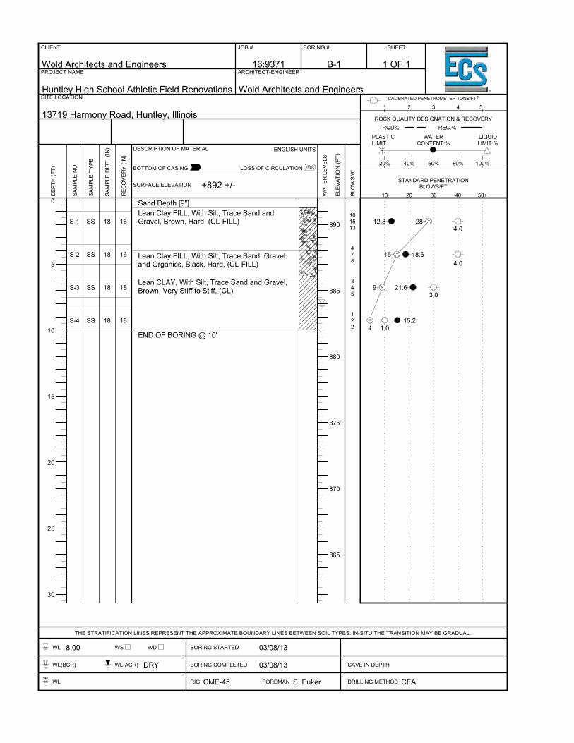
0
5
10
15
20
25
30
890
885
880
875
870
865
S-1
S-2
S-3
S-4
SS
SS
SS
SS
18
18
18
18
16
16
18
18
Sand Depth [9"]Lean Clay FILL, With Silt, Trace Sand andGravel, Brown, Hard, (CL-FILL)
Lean Clay FILL, With Silt, Trace Sand, Graveland Organics, Black, Hard, (CL-FILL)
Lean CLAY, With Silt, Trace Sand and Gravel,Brown, Very Stiff to Stiff, (CL)
END OF BORING @ 10'
101513
478
345
122
2812.84.0
15 18.64.0
9 21.63.0
415.2
1.0
CLIENT
Wold Architects and Engineers
JOB #
16:9371
BORING #
B-1
SHEET
PROJECT NAME
Huntley High School Athletic Field Renovations
ARCHITECT-ENGINEER
Wold Architects and EngineersSITE LOCATION
13719 Harmony Road, Huntley, Illinois
THE STRATIFICATION LINES REPRESENT THE APPROXIMATE BOUNDARY LINES BETWEEN SOIL TYPES. IN-SITU THE TRANSITION MAY BE GRADUAL.
WL 8.00 WS WD BORING STARTED 03/08/13
WL(BCR) WL(ACR) DRY BORING COMPLETED 03/08/13 CAVE IN DEPTH
WL RIG CME-45 FOREMAN S. Euker DRILLING METHOD CFA
DEP
TH (F
T)
SAM
PLE
NO
.
SAM
PLE
TYPE
SAM
PLE
DIS
T. (I
N)
REC
OVE
RY
(IN)
SURFACE ELEVATION
DESCRIPTION OF MATERIAL
WAT
ER L
EVEL
S
ELEV
ATIO
N (F
T)
BLO
WS/
6"
10 20 30 40 50+
20% 40% 60% 80% 100%
1 2 3 4 5+
ENGLISH UNITS
BOTTOM OF CASING LOSS OF CIRCULATION
CALIBRATED PENETROMETER TONS/FT2
PLASTICLIMIT
WATERCONTENT %
LIQUIDLIMIT %
ROCK QUALITY DESIGNATION & RECOVERYRQD% REC.%
STANDARD PENETRATIONBLOWS/FT+892 +/-
1 OF 1

0
5
10
15
20
25
30
885
880
875
870
865
860
S-1
S-2
S-3
S-4
SS
SS
SS
SS
18
18
18
18
18
16
18
18
Sand Depth [8"]Lean Clay FILL, With SIlt, Trace Sand, Graveland Organics, Dark Brown and Black, Very Stiff,(CL-FILL)
Organic CLAY, Black, Very Stiff, (OL)
Organic PEAT, Brown, (PT)
END OF BORING @ 10'
151920
535
345
212
3925.2
3.5
8
25.2
2.5
9 33.83.0
3231.6
1.5
CLIENT
Wold Architects and Engineers
JOB #
16:9371
BORING #
B-2
SHEET
PROJECT NAME
Huntley High School Athletic Field Renovations
ARCHITECT-ENGINEER
Wold Architects and EngineersSITE LOCATION
13719 Harmony Road, Huntley, Illinois
THE STRATIFICATION LINES REPRESENT THE APPROXIMATE BOUNDARY LINES BETWEEN SOIL TYPES. IN-SITU THE TRANSITION MAY BE GRADUAL.
WL DRY WS WD BORING STARTED 03/08/13
WL(BCR) WL(ACR) DRY BORING COMPLETED 03/08/13 CAVE IN DEPTH
WL RIG CME-45 FOREMAN S. Euker DRILLING METHOD CFA
DEP
TH (F
T)
SAM
PLE
NO
.
SAM
PLE
TYPE
SAM
PLE
DIS
T. (I
N)
REC
OVE
RY
(IN)
SURFACE ELEVATION
DESCRIPTION OF MATERIAL
WAT
ER L
EVEL
S
ELEV
ATIO
N (F
T)
BLO
WS/
6"
10 20 30 40 50+
20% 40% 60% 80% 100%
1 2 3 4 5+
ENGLISH UNITS
BOTTOM OF CASING LOSS OF CIRCULATION
CALIBRATED PENETROMETER TONS/FT2
PLASTICLIMIT
WATERCONTENT %
LIQUIDLIMIT %
ROCK QUALITY DESIGNATION & RECOVERYRQD% REC.%
STANDARD PENETRATIONBLOWS/FT+888 +/-
1 OF 1

0
5
10
15
20
25
30
890
885
880
875
870
865
S-1
S-2
S-3
S-4
SS
SS
SS
SS
18
18
18
18
18
18
18
5
Sand Depth [10"]Lean Clay FILL, With Silt, Trace Sand andGravel, Dark Brown, Very Stiff, (CL-FILL)
Lean CLAY, With Silt, Trace Sand and Gravel,Brown, Hard to Very Stiff, (CL)
END OF BORING @ 10'
101112
6710
589
91013
2316.4
3.0
1713.04.0
1714.13.5
2311.0
2.5
CLIENT
Wold Architects and Engineers
JOB #
16:9371
BORING #
B-3
SHEET
PROJECT NAME
Huntley High School Athletic Field Renovations
ARCHITECT-ENGINEER
Wold Architects and EngineersSITE LOCATION
13719 Harmony Road, Huntley, Illinois
THE STRATIFICATION LINES REPRESENT THE APPROXIMATE BOUNDARY LINES BETWEEN SOIL TYPES. IN-SITU THE TRANSITION MAY BE GRADUAL.
WL DRY WS WD BORING STARTED 03/07/13
WL(BCR) WL(ACR) DRY BORING COMPLETED 03/07/13 CAVE IN DEPTH
WL RIG CME-45 FOREMAN S. Euker DRILLING METHOD CFA
DEP
TH (F
T)
SAM
PLE
NO
.
SAM
PLE
TYPE
SAM
PLE
DIS
T. (I
N)
REC
OVE
RY
(IN)
SURFACE ELEVATION
DESCRIPTION OF MATERIAL
WAT
ER L
EVEL
S
ELEV
ATIO
N (F
T)
BLO
WS/
6"
10 20 30 40 50+
20% 40% 60% 80% 100%
1 2 3 4 5+
ENGLISH UNITS
BOTTOM OF CASING LOSS OF CIRCULATION
CALIBRATED PENETROMETER TONS/FT2
PLASTICLIMIT
WATERCONTENT %
LIQUIDLIMIT %
ROCK QUALITY DESIGNATION & RECOVERYRQD% REC.%
STANDARD PENETRATIONBLOWS/FT+891 +/-
1 OF 1

0
5
10
15
20
25
30
895
890
885
880
875
870
865
S-1
S-2
S-3
S-4
SS
SS
SS
SS
18
18
18
18
18
18
18
18
Sand Depth [7"]Lean Clay FILL, With Silt, Trace Sand andGravel, Brown, Very Stiff, (CL- FILL)
Lean CLAY, With Silt, Trace Sand and Gravel,Brown, Very Stiff to Stiff, (CL)
END OF BORING @ 10'
10117
546
578
556
1812.7
2.0
10 22.62.5
15 16.93.0
1117.0
1.5
CLIENT
Wold Architects and Engineers
JOB #
16:9371
BORING #
B-4
SHEET
PROJECT NAME
Huntley High School Athletic Field Renovations
ARCHITECT-ENGINEER
Wold Architects and EngineersSITE LOCATION
13719 Harmony Road, Huntley, Illinois
THE STRATIFICATION LINES REPRESENT THE APPROXIMATE BOUNDARY LINES BETWEEN SOIL TYPES. IN-SITU THE TRANSITION MAY BE GRADUAL.
WL DRY WS WD BORING STARTED 03/07/13
WL(BCR) WL(ACR) DRY BORING COMPLETED 03/07/13 CAVE IN DEPTH
WL RIG CME-45 FOREMAN S. Euker DRILLING METHOD CFA
DEP
TH (F
T)
SAM
PLE
NO
.
SAM
PLE
TYPE
SAM
PLE
DIS
T. (I
N)
REC
OVE
RY
(IN)
SURFACE ELEVATION
DESCRIPTION OF MATERIAL
WAT
ER L
EVEL
S
ELEV
ATIO
N (F
T)
BLO
WS/
6"
10 20 30 40 50+
20% 40% 60% 80% 100%
1 2 3 4 5+
ENGLISH UNITS
BOTTOM OF CASING LOSS OF CIRCULATION
CALIBRATED PENETROMETER TONS/FT2
PLASTICLIMIT
WATERCONTENT %
LIQUIDLIMIT %
ROCK QUALITY DESIGNATION & RECOVERYRQD% REC.%
STANDARD PENETRATIONBLOWS/FT+895 +/-
1 OF 1

0
5
10
15
20
25
30
890
885
880
875
870
865
S-1
S-2
S-3
S-4
SS
SS
SS
SS
18
18
18
18
18
6
18
18
Sand Depth [6"]Lean Clay FILL, With Silt, Trace Sand andGravel, Brown, Very Stiff, (CL FILL)
Lean CLAY, With Silt, Trace Sand and Gravel,Brown, Hard to Very Stiff, (CL)
END OF BORING @ 10'
10105
377
346
346
15 18.03.5
14 15.24.5+
10 17.73.5
1017.0
2.0
CLIENT
Wold Architects and Engineers
JOB #
16:9371
BORING #
B-5
SHEET
PROJECT NAME
Huntley High School Athletic Field Renovations
ARCHITECT-ENGINEER
Wold Architects and EngineersSITE LOCATION
13719 Harmony Road, Huntley, Illinois
THE STRATIFICATION LINES REPRESENT THE APPROXIMATE BOUNDARY LINES BETWEEN SOIL TYPES. IN-SITU THE TRANSITION MAY BE GRADUAL.
WL DRY WS WD BORING STARTED 03/07/13
WL(BCR) WL(ACR) DRY BORING COMPLETED 03/07/13 CAVE IN DEPTH
WL RIG CME-45 FOREMAN S. Euker DRILLING METHOD CFA
DEP
TH (F
T)
SAM
PLE
NO
.
SAM
PLE
TYPE
SAM
PLE
DIS
T. (I
N)
REC
OVE
RY
(IN)
SURFACE ELEVATION
DESCRIPTION OF MATERIAL
WAT
ER L
EVEL
S
ELEV
ATIO
N (F
T)
BLO
WS/
6"
10 20 30 40 50+
20% 40% 60% 80% 100%
1 2 3 4 5+
ENGLISH UNITS
BOTTOM OF CASING LOSS OF CIRCULATION
CALIBRATED PENETROMETER TONS/FT2
PLASTICLIMIT
WATERCONTENT %
LIQUIDLIMIT %
ROCK QUALITY DESIGNATION & RECOVERYRQD% REC.%
STANDARD PENETRATIONBLOWS/FT+894 +/-
1 OF 1

0
5
10
15
20
25
30
890
885
880
875
870
865
S-1
S-2
S-3
S-4
SS
SS
SS
SS
18
18
18
18
18
14
18
18
Sand Depth [5"]Lean Clay FILL, With Silt, Trace Sand, Graveland Organics, Brown to Black, Very Stiff, (CL-FILL)
Lean CLAY, With Silt, Trace Sand and Gravel,Brown to Gray at 8 Feet, Hard to Very Stiff, (CL)
END OF BORING @ 10'
1299
356
356
445
1824.7
2.5
1116.1 4.5+
1117.7 2.5
916.0
3.0
CLIENT
Wold Architects and Engineers
JOB #
16:9371
BORING #
B-6
SHEET
PROJECT NAME
Huntley High School Athletic Field Renovations
ARCHITECT-ENGINEER
Wold Architects and EngineersSITE LOCATION
13719 Harmony Road, Huntley, Illinois
THE STRATIFICATION LINES REPRESENT THE APPROXIMATE BOUNDARY LINES BETWEEN SOIL TYPES. IN-SITU THE TRANSITION MAY BE GRADUAL.
WL DRY WS WD BORING STARTED 03/07/13
WL(BCR) WL(ACR) DRY BORING COMPLETED 03/07/13 CAVE IN DEPTH
WL RIG CME-45 FOREMAN S. Euker DRILLING METHOD CFA
DEP
TH (F
T)
SAM
PLE
NO
.
SAM
PLE
TYPE
SAM
PLE
DIS
T. (I
N)
REC
OVE
RY
(IN)
SURFACE ELEVATION
DESCRIPTION OF MATERIAL
WAT
ER L
EVEL
S
ELEV
ATIO
N (F
T)
BLO
WS/
6"
10 20 30 40 50+
20% 40% 60% 80% 100%
1 2 3 4 5+
ENGLISH UNITS
BOTTOM OF CASING LOSS OF CIRCULATION
CALIBRATED PENETROMETER TONS/FT2
PLASTICLIMIT
WATERCONTENT %
LIQUIDLIMIT %
ROCK QUALITY DESIGNATION & RECOVERYRQD% REC.%
STANDARD PENETRATIONBLOWS/FT+891 +/-
1 OF 1

0
5
10
15
20
25
30
890
885
880
875
870
865
860
S-1
S-2
S-3
S-4
SS
SS
SS
SS
18
18
18
18
18
18
18
18
Topsoil Depth [8"]Lean Clay FILL, With Silt, Trace Sand andGravel, Dark Brown, Very Stiff, (CL-FILL)
Lean CLAY, With Silt, Trace Sand and Gravel,Brown, Hard, (CL)
END OF BORING @ 10'
1088
7812
7810
71012
16 22.72.0
2018.64.5+
1817.24.5+
2216.8
4.5
CLIENT
Wold Architects and Engineers
JOB #
16:9371
BORING #
B-7
SHEET
PROJECT NAME
Huntley High School Athletic Field Renovations
ARCHITECT-ENGINEER
Wold Architects and EngineersSITE LOCATION
13719 Harmony Road, Huntley, Illinois
THE STRATIFICATION LINES REPRESENT THE APPROXIMATE BOUNDARY LINES BETWEEN SOIL TYPES. IN-SITU THE TRANSITION MAY BE GRADUAL.
WL DRY WS WD BORING STARTED 03/07/13
WL(BCR) WL(ACR) DRY BORING COMPLETED 03/07/13 CAVE IN DEPTH
WL RIG CME-45 FOREMAN S. Euker DRILLING METHOD CFA
DEP
TH (F
T)
SAM
PLE
NO
.
SAM
PLE
TYPE
SAM
PLE
DIS
T. (I
N)
REC
OVE
RY
(IN)
SURFACE ELEVATION
DESCRIPTION OF MATERIAL
WAT
ER L
EVEL
S
ELEV
ATIO
N (F
T)
BLO
WS/
6"
10 20 30 40 50+
20% 40% 60% 80% 100%
1 2 3 4 5+
ENGLISH UNITS
BOTTOM OF CASING LOSS OF CIRCULATION
CALIBRATED PENETROMETER TONS/FT2
PLASTICLIMIT
WATERCONTENT %
LIQUIDLIMIT %
ROCK QUALITY DESIGNATION & RECOVERYRQD% REC.%
STANDARD PENETRATIONBLOWS/FT+890 +/-
1 OF 1

0
5
10
15
20
25
30
890
885
880
875
870
865
S-1
S-2
S-3
S-4
SS
SS
SS
SS
18
18
18
18
14
14
12
18
Topsoil Depth [6"]Lean Clay FILL, With Silt, Trace Sand andGravel, Dark Brown, Very Stiff to Stiff, (CL FILL)
Lean CLAY, With Silt, Trace Sand and Gravel,Brown, Stiff to Very Stiff, (CL)
END OF BORING @ 10'
434
212
225
223
7 19.83.0
320.11.0
7 28.41.0
5 13.9 2.0
CLIENT
Wold Architects and Engineers
JOB #
16:9371
BORING #
B-8
SHEET
PROJECT NAME
Huntley High School Athletic Field Renovations
ARCHITECT-ENGINEER
Wold Architects and EngineersSITE LOCATION
13719 Harmony Road, Huntley, Illinois
THE STRATIFICATION LINES REPRESENT THE APPROXIMATE BOUNDARY LINES BETWEEN SOIL TYPES. IN-SITU THE TRANSITION MAY BE GRADUAL.
WL DRY WS WD BORING STARTED 03/07/13
WL(BCR) WL(ACR) DRY BORING COMPLETED 03/07/13 CAVE IN DEPTH
WL RIG CME-45 FOREMAN S. Euker DRILLING METHOD CFA
DEP
TH (F
T)
SAM
PLE
NO
.
SAM
PLE
TYPE
SAM
PLE
DIS
T. (I
N)
REC
OVE
RY
(IN)
SURFACE ELEVATION
DESCRIPTION OF MATERIAL
WAT
ER L
EVEL
S
ELEV
ATIO
N (F
T)
BLO
WS/
6"
10 20 30 40 50+
20% 40% 60% 80% 100%
1 2 3 4 5+
ENGLISH UNITS
BOTTOM OF CASING LOSS OF CIRCULATION
CALIBRATED PENETROMETER TONS/FT2
PLASTICLIMIT
WATERCONTENT %
LIQUIDLIMIT %
ROCK QUALITY DESIGNATION & RECOVERYRQD% REC.%
STANDARD PENETRATIONBLOWS/FT+891 +/-
1 OF 1
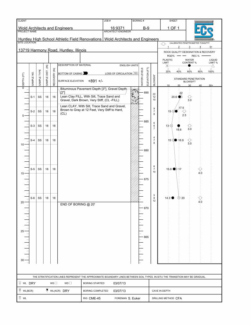
0
5
10
15
20
25
30
890
885
880
875
870
865
S-1
S-2
S-3
S-4
S-5
S-6
SS
SS
SS
SS
SS
SS
18
18
18
18
18
18
18
18
18
18
18
18
Bituminous Pavement Depth [3"], Gravel Depth[2"]Lean Clay FILL, With Silt, Trace Sand andGravel, Dark Brown, Very Stiff, (CL -FILL)
Lean CLAY, With Silt, Trace Sand and Gravel,Brown to Gray at 12 Feet, Very Stiff to Hard,(CL)
END OF BORING @ 20'
221210
978
667
478
6710
5812
2220.6
3.0
1517.5
2.5
1319.8 3.0
15 16.93.0
1715.64.0
2014.34.0
CLIENT
Wold Architects and Engineers
JOB #
16:9371
BORING #
B-9
SHEET
PROJECT NAME
Huntley High School Athletic Field Renovations
ARCHITECT-ENGINEER
Wold Architects and EngineersSITE LOCATION
13719 Harmony Road, Huntley, Illinois
THE STRATIFICATION LINES REPRESENT THE APPROXIMATE BOUNDARY LINES BETWEEN SOIL TYPES. IN-SITU THE TRANSITION MAY BE GRADUAL.
WL DRY WS WD BORING STARTED 03/07/13
WL(BCR) WL(ACR) DRY BORING COMPLETED 03/07/13 CAVE IN DEPTH
WL RIG CME-45 FOREMAN S. Euker DRILLING METHOD CFA
DEP
TH (F
T)
SAM
PLE
NO
.
SAM
PLE
TYPE
SAM
PLE
DIS
T. (I
N)
REC
OVE
RY
(IN)
SURFACE ELEVATION
DESCRIPTION OF MATERIAL
WAT
ER L
EVEL
S
ELEV
ATIO
N (F
T)
BLO
WS/
6"
10 20 30 40 50+
20% 40% 60% 80% 100%
1 2 3 4 5+
ENGLISH UNITS
BOTTOM OF CASING LOSS OF CIRCULATION
CALIBRATED PENETROMETER TONS/FT2
PLASTICLIMIT
WATERCONTENT %
LIQUIDLIMIT %
ROCK QUALITY DESIGNATION & RECOVERYRQD% REC.%
STANDARD PENETRATIONBLOWS/FT+891 +/-
1 OF 1

0
5
10
15
20
25
30
890
885
880
875
870
865
S-1
S-2
S-3
S-4
S-5
S-6
SS
SS
SS
SS
SS
SS
18
18
18
18
18
18
16
18
18
18
18
18
Lean Clay FILL, With Silt, Trace Sand andGravel, Dark Brown, Very Stiff, (CL-FILL)
Lean CLAY, With Silt, Trace Sand and Gravel,Brown to Gray at 12 Feet, Very Stiff to Hard,(CL)
END OF BORING @ 20'
968
554
457
489
5710
5810
14 22.93.5
9 18.52.0
12 19.13.0
1714.2
2.5
1713.94.5+
1815.84.0
CLIENT
Wold Architects and Engineers
JOB #
16:9371
BORING #
B-10
SHEET
PROJECT NAME
Huntley High School Athletic Field Renovations
ARCHITECT-ENGINEER
Wold Architects and EngineersSITE LOCATION
13719 Harmony Road, Huntley, Illinois
THE STRATIFICATION LINES REPRESENT THE APPROXIMATE BOUNDARY LINES BETWEEN SOIL TYPES. IN-SITU THE TRANSITION MAY BE GRADUAL.
WL DRY WS WD BORING STARTED 03/07/13
WL(BCR) WL(ACR) DRY BORING COMPLETED 03/07/13 CAVE IN DEPTH
WL RIG CME-45 FOREMAN S. Euker DRILLING METHOD CFA
DEP
TH (F
T)
SAM
PLE
NO
.
SAM
PLE
TYPE
SAM
PLE
DIS
T. (I
N)
REC
OVE
RY
(IN)
SURFACE ELEVATION
DESCRIPTION OF MATERIAL
WAT
ER L
EVEL
S
ELEV
ATIO
N (F
T)
BLO
WS/
6"
10 20 30 40 50+
20% 40% 60% 80% 100%
1 2 3 4 5+
ENGLISH UNITS
BOTTOM OF CASING LOSS OF CIRCULATION
CALIBRATED PENETROMETER TONS/FT2
PLASTICLIMIT
WATERCONTENT %
LIQUIDLIMIT %
ROCK QUALITY DESIGNATION & RECOVERYRQD% REC.%
STANDARD PENETRATIONBLOWS/FT+891 +/-
1 OF 1
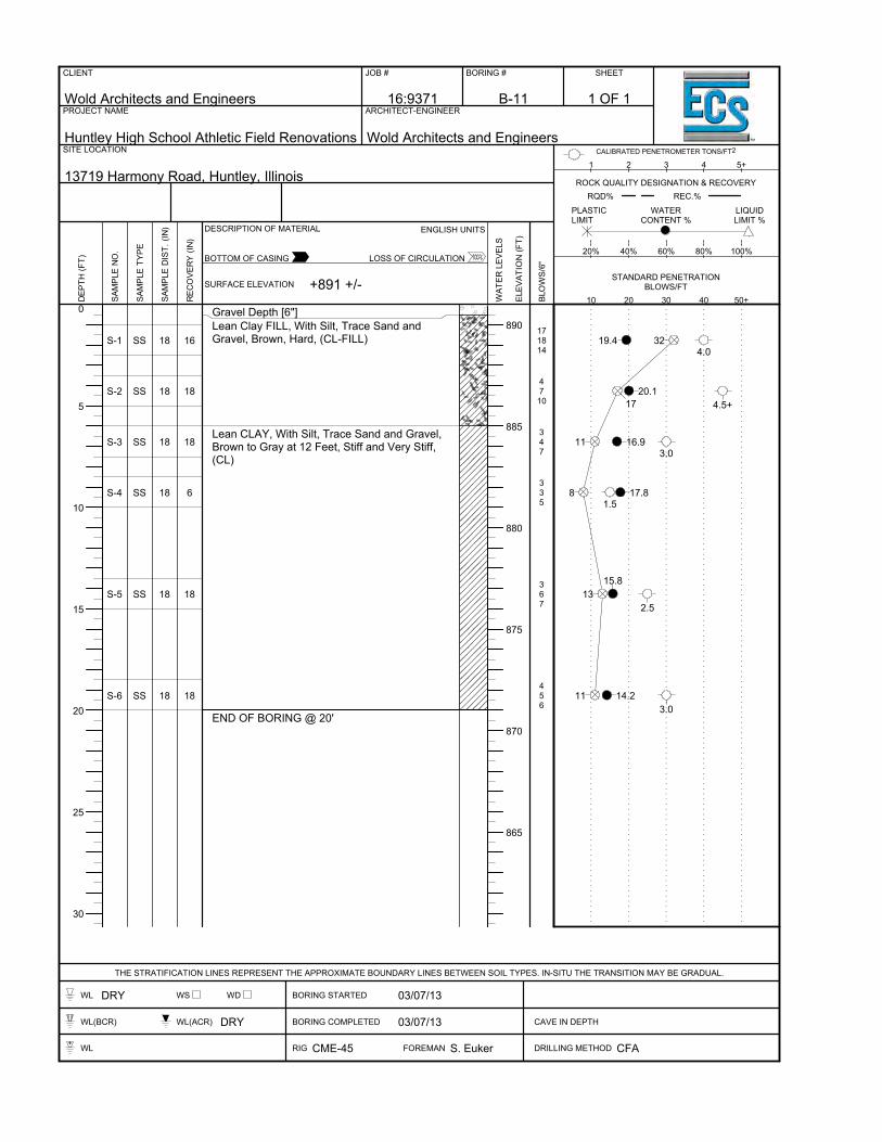
0
5
10
15
20
25
30
890
885
880
875
870
865
S-1
S-2
S-3
S-4
S-5
S-6
SS
SS
SS
SS
SS
SS
18
18
18
18
18
18
16
18
18
6
18
18
Gravel Depth [6"]Lean Clay FILL, With Silt, Trace Sand andGravel, Brown, Hard, (CL-FILL)
Lean CLAY, With Silt, Trace Sand and Gravel,Brown to Gray at 12 Feet, Stiff and Very Stiff,(CL)
END OF BORING @ 20'
171814
4710
347
335
367
456
3219.44.0
1720.1
4.5+
11 16.93.0
8 17.81.5
1315.8
2.5
11 14.23.0
CLIENT
Wold Architects and Engineers
JOB #
16:9371
BORING #
B-11
SHEET
PROJECT NAME
Huntley High School Athletic Field Renovations
ARCHITECT-ENGINEER
Wold Architects and EngineersSITE LOCATION
13719 Harmony Road, Huntley, Illinois
THE STRATIFICATION LINES REPRESENT THE APPROXIMATE BOUNDARY LINES BETWEEN SOIL TYPES. IN-SITU THE TRANSITION MAY BE GRADUAL.
WL DRY WS WD BORING STARTED 03/07/13
WL(BCR) WL(ACR) DRY BORING COMPLETED 03/07/13 CAVE IN DEPTH
WL RIG CME-45 FOREMAN S. Euker DRILLING METHOD CFA
DEP
TH (F
T)
SAM
PLE
NO
.
SAM
PLE
TYPE
SAM
PLE
DIS
T. (I
N)
REC
OVE
RY
(IN)
SURFACE ELEVATION
DESCRIPTION OF MATERIAL
WAT
ER L
EVEL
S
ELEV
ATIO
N (F
T)
BLO
WS/
6"
10 20 30 40 50+
20% 40% 60% 80% 100%
1 2 3 4 5+
ENGLISH UNITS
BOTTOM OF CASING LOSS OF CIRCULATION
CALIBRATED PENETROMETER TONS/FT2
PLASTICLIMIT
WATERCONTENT %
LIQUIDLIMIT %
ROCK QUALITY DESIGNATION & RECOVERYRQD% REC.%
STANDARD PENETRATIONBLOWS/FT+891 +/-
1 OF 1

0
5
10
15
20
25
30
890
885
880
875
870
865
S-1
S-2
S-3
S-4
S-5
S-6
SS
SS
SS
SS
SS
SS
18
18
18
18
18
18
18
18
16
18
18
18
Gravel Depth [11"]Lean Clay FILL, With Silt, Trace Sand andGravel, Dark Brown, Hard, (CL-FILL)
Lean CLAY, With Silt, Trace Sand and Gravel,Brown to Gray at 12 Feet, Stiff and Very Stiff,(CL)
END OF BORING @ 20'
181515
369
234
665
457
556
3018.8
1520.7
4.5+
7 21.41.5
11 19.53.5
1215.7 2.5
11 14.93.0
CLIENT
Wold Architects and Engineers
JOB #
16:9371
BORING #
B-12
SHEET
PROJECT NAME
Huntley High School Athletic Field Renovations
ARCHITECT-ENGINEER
Wold Architects and EngineersSITE LOCATION
13719 Harmony Road, Huntley, Illinois
THE STRATIFICATION LINES REPRESENT THE APPROXIMATE BOUNDARY LINES BETWEEN SOIL TYPES. IN-SITU THE TRANSITION MAY BE GRADUAL.
WL 13.50 WS WD BORING STARTED 03/07/13
WL(BCR) WL(ACR) DRY BORING COMPLETED 03/07/13 CAVE IN DEPTH
WL RIG CME-45 FOREMAN S. Euker DRILLING METHOD CFA
DEP
TH (F
T)
SAM
PLE
NO
.
SAM
PLE
TYPE
SAM
PLE
DIS
T. (I
N)
REC
OVE
RY
(IN)
SURFACE ELEVATION
DESCRIPTION OF MATERIAL
WAT
ER L
EVEL
S
ELEV
ATIO
N (F
T)
BLO
WS/
6"
10 20 30 40 50+
20% 40% 60% 80% 100%
1 2 3 4 5+
ENGLISH UNITS
BOTTOM OF CASING LOSS OF CIRCULATION
CALIBRATED PENETROMETER TONS/FT2
PLASTICLIMIT
WATERCONTENT %
LIQUIDLIMIT %
ROCK QUALITY DESIGNATION & RECOVERYRQD% REC.%
STANDARD PENETRATIONBLOWS/FT+891 +/-
1 OF 1

0
5
10
15
20
25
30
890
885
880
875
870
865
S-1
S-2
SS
SS
18
18
18
18
Rubber Track Depth [1"], Bituminous Depth [3"],Gravel Depth [4"]Lean CLAY, With Silt, Trace Sand and Gravel,Brown, Very Stiff, (CL)
END OF BORING @ 5'
61113
678
2422.73.5
1517.1 2.5
CLIENT
Wold Architects and Engineers
JOB #
16:9371
BORING #
B-13
SHEET
PROJECT NAME
Huntley High School Athletic Field Renovations
ARCHITECT-ENGINEER
Wold Architects and EngineersSITE LOCATION
13719 Harmony Road, Huntley, Illinois
THE STRATIFICATION LINES REPRESENT THE APPROXIMATE BOUNDARY LINES BETWEEN SOIL TYPES. IN-SITU THE TRANSITION MAY BE GRADUAL.
WL DRY WS WD BORING STARTED 03/08/13
WL(BCR) WL(ACR) DRY BORING COMPLETED 03/08/13 CAVE IN DEPTH
WL RIG CME-45 FOREMAN S. Euker DRILLING METHOD CFA
DEP
TH (F
T)
SAM
PLE
NO
.
SAM
PLE
TYPE
SAM
PLE
DIS
T. (I
N)
REC
OVE
RY
(IN)
SURFACE ELEVATION
DESCRIPTION OF MATERIAL
WAT
ER L
EVEL
S
ELEV
ATIO
N (F
T)
BLO
WS/
6"
10 20 30 40 50+
20% 40% 60% 80% 100%
1 2 3 4 5+
ENGLISH UNITS
BOTTOM OF CASING LOSS OF CIRCULATION
CALIBRATED PENETROMETER TONS/FT2
PLASTICLIMIT
WATERCONTENT %
LIQUIDLIMIT %
ROCK QUALITY DESIGNATION & RECOVERYRQD% REC.%
STANDARD PENETRATIONBLOWS/FT+891 +/-
1 OF 1
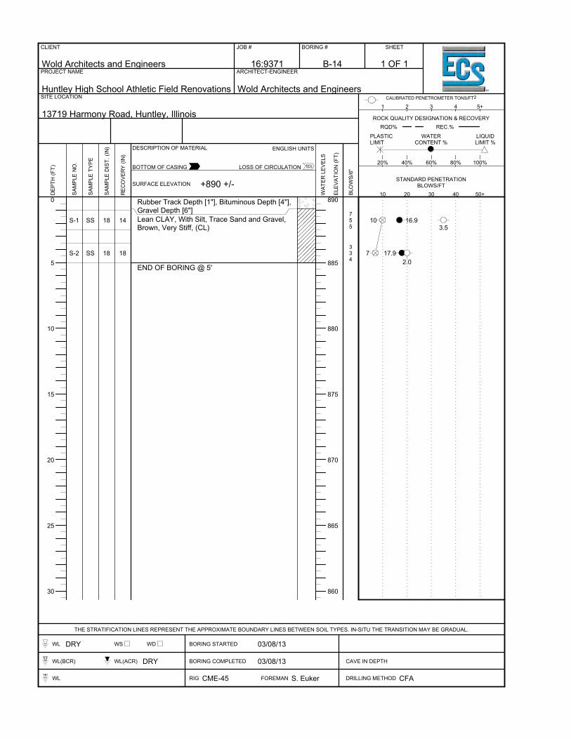
0
5
10
15
20
25
30
890
885
880
875
870
865
860
S-1
S-2
SS
SS
18
18
14
18
Rubber Track Depth [1"], Bituminous Depth [4"],Gravel Depth [6"]Lean CLAY, With Silt, Trace Sand and Gravel,Brown, Very Stiff, (CL)
END OF BORING @ 5'
755
334
10 16.93.5
7 17.92.0
CLIENT
Wold Architects and Engineers
JOB #
16:9371
BORING #
B-14
SHEET
PROJECT NAME
Huntley High School Athletic Field Renovations
ARCHITECT-ENGINEER
Wold Architects and EngineersSITE LOCATION
13719 Harmony Road, Huntley, Illinois
THE STRATIFICATION LINES REPRESENT THE APPROXIMATE BOUNDARY LINES BETWEEN SOIL TYPES. IN-SITU THE TRANSITION MAY BE GRADUAL.
WL DRY WS WD BORING STARTED 03/08/13
WL(BCR) WL(ACR) DRY BORING COMPLETED 03/08/13 CAVE IN DEPTH
WL RIG CME-45 FOREMAN S. Euker DRILLING METHOD CFA
DEP
TH (F
T)
SAM
PLE
NO
.
SAM
PLE
TYPE
SAM
PLE
DIS
T. (I
N)
REC
OVE
RY
(IN)
SURFACE ELEVATION
DESCRIPTION OF MATERIAL
WAT
ER L
EVEL
S
ELEV
ATIO
N (F
T)
BLO
WS/
6"
10 20 30 40 50+
20% 40% 60% 80% 100%
1 2 3 4 5+
ENGLISH UNITS
BOTTOM OF CASING LOSS OF CIRCULATION
CALIBRATED PENETROMETER TONS/FT2
PLASTICLIMIT
WATERCONTENT %
LIQUIDLIMIT %
ROCK QUALITY DESIGNATION & RECOVERYRQD% REC.%
STANDARD PENETRATIONBLOWS/FT+890 +/-
1 OF 1

0
5
10
15
20
25
30
890
885
880
875
870
865
S-1
S-2
SS
SS
18
18
18
18
Rubber Track Depth [1"], Bituminous Depth [4"],Gravel Depth [6"]Lean Clay FILL, With Silt, Trace Sand andGravel, Brown, Very Stiff, (CL-FILL)
Lean CLAY, With Silt, Trace Sand and Gravel,Brown, Very Stiff, (CL)
END OF BORING @ 5'
577
534
14 18.43.5
716.5 2.5
CLIENT
Wold Architects and Engineers
JOB #
16:9371
BORING #
B-15
SHEET
PROJECT NAME
Huntley High School Athletic Field Renovations
ARCHITECT-ENGINEER
Wold Architects and EngineersSITE LOCATION
13719 Harmony Road, Huntley, Illinois
THE STRATIFICATION LINES REPRESENT THE APPROXIMATE BOUNDARY LINES BETWEEN SOIL TYPES. IN-SITU THE TRANSITION MAY BE GRADUAL.
WL DRY WS WD BORING STARTED 03/08/13
WL(BCR) WL(ACR) DRY BORING COMPLETED 03/08/13 CAVE IN DEPTH
WL RIG CME-45 FOREMAN S. Euker DRILLING METHOD CFA
DEP
TH (F
T)
SAM
PLE
NO
.
SAM
PLE
TYPE
SAM
PLE
DIS
T. (I
N)
REC
OVE
RY
(IN)
SURFACE ELEVATION
DESCRIPTION OF MATERIAL
WAT
ER L
EVEL
S
ELEV
ATIO
N (F
T)
BLO
WS/
6"
10 20 30 40 50+
20% 40% 60% 80% 100%
1 2 3 4 5+
ENGLISH UNITS
BOTTOM OF CASING LOSS OF CIRCULATION
CALIBRATED PENETROMETER TONS/FT2
PLASTICLIMIT
WATERCONTENT %
LIQUIDLIMIT %
ROCK QUALITY DESIGNATION & RECOVERYRQD% REC.%
STANDARD PENETRATIONBLOWS/FT+891 +/-
1 OF 1

0
5
10
15
20
25
30
890
885
880
875
870
865
S-1
S-2
SS
SS
18
18
18
18
Rubber Track Depth [1"], Bituminous Depth [4"],Gravel Depth [7"]Lean Clay FILL, With Silt, Trace Sand andGravel, Brown, Hard, (CL-FILL)
Lean CLAY, With Silt, Trace Sand and Gravel,Brown, Very Stiff, (CL)
END OF BORING @ 5'
1497
245
16 17.64.5+
916.9 3.5
CLIENT
Wold Architects and Engineers
JOB #
16:9371
BORING #
B-16
SHEET
PROJECT NAME
Huntley High School Athletic Field Renovations
ARCHITECT-ENGINEER
Wold Architects and EngineersSITE LOCATION
13719 Harmony Road, Huntley, Illinois
THE STRATIFICATION LINES REPRESENT THE APPROXIMATE BOUNDARY LINES BETWEEN SOIL TYPES. IN-SITU THE TRANSITION MAY BE GRADUAL.
WL DRY WS WD BORING STARTED 03/08/13
WL(BCR) WL(ACR) DRY BORING COMPLETED 03/08/13 CAVE IN DEPTH
WL RIG CME-45 FOREMAN S. Euker DRILLING METHOD CFA
DEP
TH (F
T)
SAM
PLE
NO
.
SAM
PLE
TYPE
SAM
PLE
DIS
T. (I
N)
REC
OVE
RY
(IN)
SURFACE ELEVATION
DESCRIPTION OF MATERIAL
WAT
ER L
EVEL
S
ELEV
ATIO
N (F
T)
BLO
WS/
6"
10 20 30 40 50+
20% 40% 60% 80% 100%
1 2 3 4 5+
ENGLISH UNITS
BOTTOM OF CASING LOSS OF CIRCULATION
CALIBRATED PENETROMETER TONS/FT2
PLASTICLIMIT
WATERCONTENT %
LIQUIDLIMIT %
ROCK QUALITY DESIGNATION & RECOVERYRQD% REC.%
STANDARD PENETRATIONBLOWS/FT+891 +/-
1 OF 1

0
5
10
15
20
25
30
890
885
880
875
870
865
S-1
S-2
S-3
S-4
SS
SS
SS
SS
18
18
18
18
16
18
10
18
Topsoil Depth [7"]Lean CLAY, With Silt, Trace Sand and Gravel,Brown, Hard to Very Stiff, (CL)
END OF BORING @ 10'
777
578
479
457
14 17.54.0
15 18.83.0
16 18.63.0
1217.6
3.5
CLIENT
Wold Architects and Engineers
JOB #
16:9371
BORING #
B-17
SHEET
PROJECT NAME
Huntley High School Athletic Field Renovations
ARCHITECT-ENGINEER
Wold Architects and EngineersSITE LOCATION
13719 Harmony Road, Huntley, Illinois
THE STRATIFICATION LINES REPRESENT THE APPROXIMATE BOUNDARY LINES BETWEEN SOIL TYPES. IN-SITU THE TRANSITION MAY BE GRADUAL.
WL DRY WS WD BORING STARTED 03/08/13
WL(BCR) WL(ACR) DRY BORING COMPLETED 03/08/13 CAVE IN DEPTH
WL RIG CME-45 FOREMAN S. Euker DRILLING METHOD CFA
DEP
TH (F
T)
SAM
PLE
NO
.
SAM
PLE
TYPE
SAM
PLE
DIS
T. (I
N)
REC
OVE
RY
(IN)
SURFACE ELEVATION
DESCRIPTION OF MATERIAL
WAT
ER L
EVEL
S
ELEV
ATIO
N (F
T)
BLO
WS/
6"
10 20 30 40 50+
20% 40% 60% 80% 100%
1 2 3 4 5+
ENGLISH UNITS
BOTTOM OF CASING LOSS OF CIRCULATION
CALIBRATED PENETROMETER TONS/FT2
PLASTICLIMIT
WATERCONTENT %
LIQUIDLIMIT %
ROCK QUALITY DESIGNATION & RECOVERYRQD% REC.%
STANDARD PENETRATIONBLOWS/FT+891 +/-
1 OF 1

0
5
10
15
20
25
30
890
885
880
875
870
865
S-1
S-2
S-3
S-4
SS
SS
SS
SS
18
18
18
18
18
16
14
18
Topsoil Depth [11"]Lean Clay FILL, With Silt, Trace Sand, Graveland Organics, Black, Hard, (CL- FILL)
Lean CLAY, With Silt, Trace Sand and Gravel,Brown, Very Stiff to Hard, (CL)
END OF BORING @ 10'
865
347
477
457
11 20.44.5+
1123.6 3.0
14 19.43.5
1218.2
4.0
CLIENT
Wold Architects and Engineers
JOB #
16:9371
BORING #
B-18
SHEET
PROJECT NAME
Huntley High School Athletic Field Renovations
ARCHITECT-ENGINEER
Wold Architects and EngineersSITE LOCATION
13719 Harmony Road, Huntley, Illinois
THE STRATIFICATION LINES REPRESENT THE APPROXIMATE BOUNDARY LINES BETWEEN SOIL TYPES. IN-SITU THE TRANSITION MAY BE GRADUAL.
WL DRY WS WD BORING STARTED 03/08/13
WL(BCR) WL(ACR) DRY BORING COMPLETED 03/08/13 CAVE IN DEPTH
WL RIG CME-45 FOREMAN S. Euker DRILLING METHOD CFA
DEP
TH (F
T)
SAM
PLE
NO
.
SAM
PLE
TYPE
SAM
PLE
DIS
T. (I
N)
REC
OVE
RY
(IN)
SURFACE ELEVATION
DESCRIPTION OF MATERIAL
WAT
ER L
EVEL
S
ELEV
ATIO
N (F
T)
BLO
WS/
6"
10 20 30 40 50+
20% 40% 60% 80% 100%
1 2 3 4 5+
ENGLISH UNITS
BOTTOM OF CASING LOSS OF CIRCULATION
CALIBRATED PENETROMETER TONS/FT2
PLASTICLIMIT
WATERCONTENT %
LIQUIDLIMIT %
ROCK QUALITY DESIGNATION & RECOVERYRQD% REC.%
STANDARD PENETRATIONBLOWS/FT+891 +/-
1 OF 1

0
5
10
15
20
25
30
890
885
880
875
870
865
S-1
S-2
S-3
S-4
SS
SS
SS
SS
18
18
18
18
14
18
18
18
Topsoil Depth [15"]
Lean CLAY, With Silt, Trace Sand and Gravel,Brown, Hard to Stiff, (CL)
END OF BORING @ 10'
5810
667
234
233
18 21.34.5+
1317.9 4.5
7 19.12.0
617.2
1.0
CLIENT
Wold Architects and Engineers
JOB #
16:9371
BORING #
B-19
SHEET
PROJECT NAME
Huntley High School Athletic Field Renovations
ARCHITECT-ENGINEER
Wold Architects and EngineersSITE LOCATION
13719 Harmony Road, Huntley, Illinois
THE STRATIFICATION LINES REPRESENT THE APPROXIMATE BOUNDARY LINES BETWEEN SOIL TYPES. IN-SITU THE TRANSITION MAY BE GRADUAL.
WL DRY WS WD BORING STARTED 03/08/13
WL(BCR) WL(ACR) DRY BORING COMPLETED 03/08/13 CAVE IN DEPTH
WL RIG CME-45 FOREMAN S. Euker DRILLING METHOD CFA
DEP
TH (F
T)
SAM
PLE
NO
.
SAM
PLE
TYPE
SAM
PLE
DIS
T. (I
N)
REC
OVE
RY
(IN)
SURFACE ELEVATION
DESCRIPTION OF MATERIAL
WAT
ER L
EVEL
S
ELEV
ATIO
N (F
T)
BLO
WS/
6"
10 20 30 40 50+
20% 40% 60% 80% 100%
1 2 3 4 5+
ENGLISH UNITS
BOTTOM OF CASING LOSS OF CIRCULATION
CALIBRATED PENETROMETER TONS/FT2
PLASTICLIMIT
WATERCONTENT %
LIQUIDLIMIT %
ROCK QUALITY DESIGNATION & RECOVERYRQD% REC.%
STANDARD PENETRATIONBLOWS/FT+891 +/-
1 OF 1

0
5
10
15
20
25
30
890
885
880
875
870
865
S-1
S-2
S-3
S-4
SS
SS
SS
SS
18
18
18
18
16
14
16
18
Topsoil Depth [11"]Lean Clay FILL, With Silt, Trace Sand, Graveland Organics, Black, Hard, (CL- FILL)
Lean CLAY, With Silt, Trace Sand and Gravel,Brown, Stiff, (CL)
END OF BORING @ 10'
335
244
212
WOH12
8 15.84.0
8
3 19.31.0
322.6
1.0
CLIENT
Wold Architects and Engineers
JOB #
16:9371
BORING #
B-20
SHEET
PROJECT NAME
Huntley High School Athletic Field Renovations
ARCHITECT-ENGINEER
Wold Architects and EngineersSITE LOCATION
13719 Harmony Road, Huntley, Illinois
THE STRATIFICATION LINES REPRESENT THE APPROXIMATE BOUNDARY LINES BETWEEN SOIL TYPES. IN-SITU THE TRANSITION MAY BE GRADUAL.
WL 8.50 WS WD BORING STARTED 03/08/13
WL(BCR) WL(ACR) 8.50 BORING COMPLETED 03/08/13 CAVE IN DEPTH @ 9.00'
WL RIG CME-45 FOREMAN S. Euker DRILLING METHOD CFA
DEP
TH (F
T)
SAM
PLE
NO
.
SAM
PLE
TYPE
SAM
PLE
DIS
T. (I
N)
REC
OVE
RY
(IN)
SURFACE ELEVATION
DESCRIPTION OF MATERIAL
WAT
ER L
EVEL
S
ELEV
ATIO
N (F
T)
BLO
WS/
6"
10 20 30 40 50+
20% 40% 60% 80% 100%
1 2 3 4 5+
ENGLISH UNITS
BOTTOM OF CASING LOSS OF CIRCULATION
CALIBRATED PENETROMETER TONS/FT2
PLASTICLIMIT
WATERCONTENT %
LIQUIDLIMIT %
ROCK QUALITY DESIGNATION & RECOVERYRQD% REC.%
STANDARD PENETRATIONBLOWS/FT+891 +/-
1 OF 1

0
5
10
15
20
25
30
890
885
880
875
870
865
S-1
S-2
S-3
S-4
SS
SS
SS
SS
18
18
18
18
14
14
12
18
Topsoil Depth [14"]
Lean Clay FILL, With Silt, Trace Sand, Graveland Organics, Black, Hard to Very Stiff, (CL-FILL)
Lean CLAY, With Silt, Trace Sand and Gravel,Brown, Very Stiff to Stiff, (CL)
END OF BORING @ 10'
457
234
533
122
12 24.54.0
7 25.02.0
6 17.02.0
413.4
1.5
CLIENT
Wold Architects and Engineers
JOB #
16:9371
BORING #
B-21
SHEET
PROJECT NAME
Huntley High School Athletic Field Renovations
ARCHITECT-ENGINEER
Wold Architects and EngineersSITE LOCATION
13719 Harmony Road, Huntley, Illinois
THE STRATIFICATION LINES REPRESENT THE APPROXIMATE BOUNDARY LINES BETWEEN SOIL TYPES. IN-SITU THE TRANSITION MAY BE GRADUAL.
WL DRY WS WD BORING STARTED 03/08/13
WL(BCR) WL(ACR) DRY BORING COMPLETED 03/08/13 CAVE IN DEPTH
WL RIG CME-45 FOREMAN S. Euker DRILLING METHOD CFA
DEP
TH (F
T)
SAM
PLE
NO
.
SAM
PLE
TYPE
SAM
PLE
DIS
T. (I
N)
REC
OVE
RY
(IN)
SURFACE ELEVATION
DESCRIPTION OF MATERIAL
WAT
ER L
EVEL
S
ELEV
ATIO
N (F
T)
BLO
WS/
6"
10 20 30 40 50+
20% 40% 60% 80% 100%
1 2 3 4 5+
ENGLISH UNITS
BOTTOM OF CASING LOSS OF CIRCULATION
CALIBRATED PENETROMETER TONS/FT2
PLASTICLIMIT
WATERCONTENT %
LIQUIDLIMIT %
ROCK QUALITY DESIGNATION & RECOVERYRQD% REC.%
STANDARD PENETRATIONBLOWS/FT+891 +/-
1 OF 1

0
5
10
15
20
25
30
890
885
880
875
870
865
S-1
S-2
S-3
S-4
SS
SS
SS
SS
18
18
18
18
14
12
18
18
Topsoil Depth [16"]
Lean CLAY, With Silt, Trace Sand and Gravel,Brown, Hard to Stiff, (CL)
END OF BORING @ 10'
856
345
347
357
11 17.94.0
919.2 4.5
11 20.73.5
12 15.81.5
CLIENT
Wold Architects and Engineers
JOB #
16:9371
BORING #
B-22
SHEET
PROJECT NAME
Huntley High School Athletic Field Renovations
ARCHITECT-ENGINEER
Wold Architects and EngineersSITE LOCATION
13719 Harmony Road, Huntley, Illinois
THE STRATIFICATION LINES REPRESENT THE APPROXIMATE BOUNDARY LINES BETWEEN SOIL TYPES. IN-SITU THE TRANSITION MAY BE GRADUAL.
WL DRY WS WD BORING STARTED 03/08/13
WL(BCR) WL(ACR) DRY BORING COMPLETED 03/08/13 CAVE IN DEPTH
WL RIG CME-45 FOREMAN S. Euker DRILLING METHOD CFA
DEP
TH (F
T)
SAM
PLE
NO
.
SAM
PLE
TYPE
SAM
PLE
DIS
T. (I
N)
REC
OVE
RY
(IN)
SURFACE ELEVATION
DESCRIPTION OF MATERIAL
WAT
ER L
EVEL
S
ELEV
ATIO
N (F
T)
BLO
WS/
6"
10 20 30 40 50+
20% 40% 60% 80% 100%
1 2 3 4 5+
ENGLISH UNITS
BOTTOM OF CASING LOSS OF CIRCULATION
CALIBRATED PENETROMETER TONS/FT2
PLASTICLIMIT
WATERCONTENT %
LIQUIDLIMIT %
ROCK QUALITY DESIGNATION & RECOVERYRQD% REC.%
STANDARD PENETRATIONBLOWS/FT+891 +/-
1 OF 1

0
5
10
15
20
25
30
895
890
885
880
875
870
S-1
S-2
S-3
S-4
SS
SS
SS
SS
18
18
18
18
18
8
18
18
Topsoil Depth [11"]Lean CLAY, With Silt, Trace Sand and Gravel,Brown, Very Stiff, (CL)
END OF BORING @ 10'
333
4912
578
4710
615.9
3.0
2122.0
3.5
15 19.33.0
1719.3
3.5
CLIENT
Wold Architects and Engineers
JOB #
16:9371
BORING #
B-23
SHEET
PROJECT NAME
Huntley High School Athletic Field Renovations
ARCHITECT-ENGINEER
Wold Architects and EngineersSITE LOCATION
13719 Harmony Road, Huntley, Illinois
THE STRATIFICATION LINES REPRESENT THE APPROXIMATE BOUNDARY LINES BETWEEN SOIL TYPES. IN-SITU THE TRANSITION MAY BE GRADUAL.
WL DRY WS WD BORING STARTED 03/08/13
WL(BCR) WL(ACR) DRY BORING COMPLETED 03/08/13 CAVE IN DEPTH
WL RIG CME-45 FOREMAN S. Euker DRILLING METHOD CFA
DEP
TH (F
T)
SAM
PLE
NO
.
SAM
PLE
TYPE
SAM
PLE
DIS
T. (I
N)
REC
OVE
RY
(IN)
SURFACE ELEVATION
DESCRIPTION OF MATERIAL
WAT
ER L
EVEL
S
ELEV
ATIO
N (F
T)
BLO
WS/
6"
10 20 30 40 50+
20% 40% 60% 80% 100%
1 2 3 4 5+
ENGLISH UNITS
BOTTOM OF CASING LOSS OF CIRCULATION
CALIBRATED PENETROMETER TONS/FT2
PLASTICLIMIT
WATERCONTENT %
LIQUIDLIMIT %
ROCK QUALITY DESIGNATION & RECOVERYRQD% REC.%
STANDARD PENETRATIONBLOWS/FT+898 +/-
1 OF 1

0
5
10
15
20
25
30
895
890
885
880
875
870
S-1
S-2
S-3
S-4
SS
SS
SS
SS
18
18
18
18
16
16
18
18
Topsoil Depth [11"]Lean CLAY, With Silt, Trace Sand and Gravel,Brown, Very Stiff, (CL)
END OF BORING @ 10'
655
236
455
345
1019.1 2.5
9 19.42.0
10
17.02.0
920.5
2.5
CLIENT
Wold Architects and Engineers
JOB #
16:9371
BORING #
B-24
SHEET
PROJECT NAME
Huntley High School Athletic Field Renovations
ARCHITECT-ENGINEER
Wold Architects and EngineersSITE LOCATION
13719 Harmony Road, Huntley, Illinois
THE STRATIFICATION LINES REPRESENT THE APPROXIMATE BOUNDARY LINES BETWEEN SOIL TYPES. IN-SITU THE TRANSITION MAY BE GRADUAL.
WL DRY WS WD BORING STARTED 03/08/13
WL(BCR) WL(ACR) DRY BORING COMPLETED 03/08/13 CAVE IN DEPTH
WL RIG CME-45 FOREMAN S. Euker DRILLING METHOD CFA
DEP
TH (F
T)
SAM
PLE
NO
.
SAM
PLE
TYPE
SAM
PLE
DIS
T. (I
N)
REC
OVE
RY
(IN)
SURFACE ELEVATION
DESCRIPTION OF MATERIAL
WAT
ER L
EVEL
S
ELEV
ATIO
N (F
T)
BLO
WS/
6"
10 20 30 40 50+
20% 40% 60% 80% 100%
1 2 3 4 5+
ENGLISH UNITS
BOTTOM OF CASING LOSS OF CIRCULATION
CALIBRATED PENETROMETER TONS/FT2
PLASTICLIMIT
WATERCONTENT %
LIQUIDLIMIT %
ROCK QUALITY DESIGNATION & RECOVERYRQD% REC.%
STANDARD PENETRATIONBLOWS/FT+899 +/-
1 OF 1

0
5
10
15
20
25
30
890
885
880
875
870
865
S-1
S-2
S-3
S-4
SS
SS
SS
SS
18
18
18
18
16
18
18
18
Topsoil Depth [8"]Lean CLAY, With SIlt, Trace Sand and Gravel,Brown, Very Stiff and Hard, (CL)
END OF BORING @ 10'
633
346
358
689
6 18.63.0
1017.8 4.5+
13 16.73.0
1716.8
3.0
CLIENT
Wold Architects and Engineers
JOB #
16:9371
BORING #
B-25
SHEET
PROJECT NAME
Huntley High School Athletic Field Renovations
ARCHITECT-ENGINEER
Wold Architects and EngineersSITE LOCATION
13719 Harmony Road, Huntley, Illinois
THE STRATIFICATION LINES REPRESENT THE APPROXIMATE BOUNDARY LINES BETWEEN SOIL TYPES. IN-SITU THE TRANSITION MAY BE GRADUAL.
WL DRY WS WD BORING STARTED 03/08/13
WL(BCR) WL(ACR) DRY BORING COMPLETED 03/08/13 CAVE IN DEPTH
WL RIG CME-45 FOREMAN S. Euker DRILLING METHOD CFA
DEP
TH (F
T)
SAM
PLE
NO
.
SAM
PLE
TYPE
SAM
PLE
DIS
T. (I
N)
REC
OVE
RY
(IN)
SURFACE ELEVATION
DESCRIPTION OF MATERIAL
WAT
ER L
EVEL
S
ELEV
ATIO
N (F
T)
BLO
WS/
6"
10 20 30 40 50+
20% 40% 60% 80% 100%
1 2 3 4 5+
ENGLISH UNITS
BOTTOM OF CASING LOSS OF CIRCULATION
CALIBRATED PENETROMETER TONS/FT2
PLASTICLIMIT
WATERCONTENT %
LIQUIDLIMIT %
ROCK QUALITY DESIGNATION & RECOVERYRQD% REC.%
STANDARD PENETRATIONBLOWS/FT+894 +/-
1 OF 1

0
5
10
15
20
25
30
895
890
885
880
875
870
S-1
S-2
S-3
S-4
SS
SS
SS
SS
18
18
18
18
18
4
18
18
Topsoil Depth [8"]Lean CLAY, With Silt, Trace Sand and Gravel,Brown, Very Stiff to Hard, (CL)
Fine to Medium SAND, WIth Gravel, Brown,Moist, Medium Dense, (SP)END OF BORING @ 10'
11116
71115
6912
51214
17 18.13.5
2618.9
2113.24.5+
26
CLIENT
Wold Architects and Engineers
JOB #
16:9371
BORING #
B-26
SHEET
PROJECT NAME
Huntley High School Athletic Field Renovations
ARCHITECT-ENGINEER
Wold Architects and EngineersSITE LOCATION
13719 Harmony Road, Huntley, Illinois
THE STRATIFICATION LINES REPRESENT THE APPROXIMATE BOUNDARY LINES BETWEEN SOIL TYPES. IN-SITU THE TRANSITION MAY BE GRADUAL.
WL 9.50 WS WD BORING STARTED 03/08/13
WL(BCR) WL(ACR) 9.50 BORING COMPLETED 03/08/13 CAVE IN DEPTH
WL RIG CME-45 FOREMAN S. Euker DRILLING METHOD CFA
DEP
TH (F
T)
SAM
PLE
NO
.
SAM
PLE
TYPE
SAM
PLE
DIS
T. (I
N)
REC
OVE
RY
(IN)
SURFACE ELEVATION
DESCRIPTION OF MATERIAL
WAT
ER L
EVEL
S
ELEV
ATIO
N (F
T)
BLO
WS/
6"
10 20 30 40 50+
20% 40% 60% 80% 100%
1 2 3 4 5+
ENGLISH UNITS
BOTTOM OF CASING LOSS OF CIRCULATION
CALIBRATED PENETROMETER TONS/FT2
PLASTICLIMIT
WATERCONTENT %
LIQUIDLIMIT %
ROCK QUALITY DESIGNATION & RECOVERYRQD% REC.%
STANDARD PENETRATIONBLOWS/FT+898 +/-
1 OF 1

0
5
10
15
20
25
30
890
885
880
875
870
865
S-1
S-2
S-3
S-4
S-5
S-6
SS
SS
SS
SS
SS
SS
18
18
18
18
18
18
14
14
18
18
18
18
Topsoil Depth [17"]
Lean CLAY, With Silt, Trace Sand and Gravel,Brown to Gray at 12 Feet, Very Stiff and Hard,(CL)
END OF BORING @ 20'
234
235
557
467
91213
5710
7 17.72.0
817.1 2.5
1214.6
2.0
1316.2
2.0
2517.84.5+
1714.83.5
CLIENT
Wold Architects and Engineers
JOB #
16:9371
BORING #
B-27
SHEET
PROJECT NAME
Huntley High School Athletic Field Renovations
ARCHITECT-ENGINEER
Wold Architects and EngineersSITE LOCATION
13719 Harmony Road, Huntley, Illinois
THE STRATIFICATION LINES REPRESENT THE APPROXIMATE BOUNDARY LINES BETWEEN SOIL TYPES. IN-SITU THE TRANSITION MAY BE GRADUAL.
WL DRY WS WD BORING STARTED 03/08/13
WL(BCR) WL(ACR) DRY BORING COMPLETED 03/08/13 CAVE IN DEPTH
WL RIG CME-45 FOREMAN S. Euker DRILLING METHOD CFA
DEP
TH (F
T)
SAM
PLE
NO
.
SAM
PLE
TYPE
SAM
PLE
DIS
T. (I
N)
REC
OVE
RY
(IN)
SURFACE ELEVATION
DESCRIPTION OF MATERIAL
WAT
ER L
EVEL
S
ELEV
ATIO
N (F
T)
BLO
WS/
6"
10 20 30 40 50+
20% 40% 60% 80% 100%
1 2 3 4 5+
ENGLISH UNITS
BOTTOM OF CASING LOSS OF CIRCULATION
CALIBRATED PENETROMETER TONS/FT2
PLASTICLIMIT
WATERCONTENT %
LIQUIDLIMIT %
ROCK QUALITY DESIGNATION & RECOVERYRQD% REC.%
STANDARD PENETRATIONBLOWS/FT+893 +/-
1 OF 1

0
5
10
15
20
25
30
885
880
875
870
865
860
S-1
S-2
S-3
S-4
S-5
S-6
SS
SS
SS
SS
SS
SS
18
18
18
18
18
18
18
18
18
18
18
18
Bituminous Depth [4"], Gravel Depth [12"]
Lean CLAY, With Silt, Trace Sand and Gravel,Brown to Gray at 12 Feet, Very Stiff, (CL)
END OF BORING @ 20'
466
455
478
4710
478
667
1216.3 2.5
1018.9
2.0
15 14.83.0
17 19.43.0
15 16.83.0
13 14.13.0
CLIENT
Wold Architects and Engineers
JOB #
16:9371
BORING #
B-28
SHEET
PROJECT NAME
Huntley High School Athletic Field Renovations
ARCHITECT-ENGINEER
Wold Architects and EngineersSITE LOCATION
13719 Harmony Road, Huntley, Illinois
THE STRATIFICATION LINES REPRESENT THE APPROXIMATE BOUNDARY LINES BETWEEN SOIL TYPES. IN-SITU THE TRANSITION MAY BE GRADUAL.
WL 1.00 WS WD BORING STARTED 03/07/13
WL(BCR) WL(ACR) 1.50 BORING COMPLETED 03/07/13 CAVE IN DEPTH
WL RIG CME-45 FOREMAN S. Euker DRILLING METHOD CFA
DEP
TH (F
T)
SAM
PLE
NO
.
SAM
PLE
TYPE
SAM
PLE
DIS
T. (I
N)
REC
OVE
RY
(IN)
SURFACE ELEVATION
DESCRIPTION OF MATERIAL
WAT
ER L
EVEL
S
ELEV
ATIO
N (F
T)
BLO
WS/
6"
10 20 30 40 50+
20% 40% 60% 80% 100%
1 2 3 4 5+
ENGLISH UNITS
BOTTOM OF CASING LOSS OF CIRCULATION
CALIBRATED PENETROMETER TONS/FT2
PLASTICLIMIT
WATERCONTENT %
LIQUIDLIMIT %
ROCK QUALITY DESIGNATION & RECOVERYRQD% REC.%
STANDARD PENETRATIONBLOWS/FT+888 +/-
1 OF 1

0
5
10
15
20
25
30
885
880
875
870
865
860
S-1
S-2
S-3
S-4
S-5
S-6
SS
SS
SS
SS
SS
SS
18
18
18
18
18
18
18
18
18
18
18
18
Bituminous Depth [4"], Gravel Depth [14"]
Lean Clay FILL, With Silt, Trace Sand, Graveland Organics, Black, Very Stiff to Stiff, (CL-FILL)
Lean CLAY, With Silt, Trace Sand and Gravel,Brown to Gray at 14 Feet, Stiff to Hard, (CL)
END OF BORING @ 20'
424
234
245
235
5811
6811
6 21.62.0
725.31.5
917.7
2.0
8 16.21.0
1916.43.0
1913.94.5+
CLIENT
Wold Architects and Engineers
JOB #
16:9371
BORING #
B-29
SHEET
PROJECT NAME
Huntley High School Athletic Field Renovations
ARCHITECT-ENGINEER
Wold Architects and EngineersSITE LOCATION
13719 Harmony Road, Huntley, Illinois
THE STRATIFICATION LINES REPRESENT THE APPROXIMATE BOUNDARY LINES BETWEEN SOIL TYPES. IN-SITU THE TRANSITION MAY BE GRADUAL.
WL DRY WS WD BORING STARTED 03/07/13
WL(BCR) WL(ACR) DRY BORING COMPLETED 03/07/13 CAVE IN DEPTH
WL RIG CME-45 FOREMAN S. Euker DRILLING METHOD CFA
DEP
TH (F
T)
SAM
PLE
NO
.
SAM
PLE
TYPE
SAM
PLE
DIS
T. (I
N)
REC
OVE
RY
(IN)
SURFACE ELEVATION
DESCRIPTION OF MATERIAL
WAT
ER L
EVEL
S
ELEV
ATIO
N (F
T)
BLO
WS/
6"
10 20 30 40 50+
20% 40% 60% 80% 100%
1 2 3 4 5+
ENGLISH UNITS
BOTTOM OF CASING LOSS OF CIRCULATION
CALIBRATED PENETROMETER TONS/FT2
PLASTICLIMIT
WATERCONTENT %
LIQUIDLIMIT %
ROCK QUALITY DESIGNATION & RECOVERYRQD% REC.%
STANDARD PENETRATIONBLOWS/FT+889 +/-
1 OF 1

UNIFIED SOIL CLASSIFICATION SYSTEM (ASTM D 2487)
Major Divisions
Group Symbols
Typical Names Laboratory Classification Criteria
GW
Well-graded gravels, gravel-sand mixtures, little or no fines
Cu = D60/D10 greater than 4 Cc = (D30)
2/(D10xD60) between 1 and 3
Cle
an g
rave
ls
(Litt
le o
r no
fin
es)
GP
Poorly graded gravels, gravel-sand mixtures, little or no fines
Not meeting all gradation requirements for GW
d
GMa
u
Silty gravels, gravel-sand mixtures
Atterberg limits below “A” line or P.I. less than 4
Gra
vels
(M
ore
than
hal
f of c
oars
e fr
actio
n is
la
rger
than
No.
4 s
ieve
siz
e)
Gra
vels
with
fine
s (A
ppre
ciab
le a
mou
nt o
f fin
es)
GC
Clayey gravels, gravel-sand-clay mixtures
Atterberg limits below “A” line or P.I. less than 7
Above “A” line with P.I. between 4 and 7 are borderline cases requiring use of dual symbols
SW
Well-graded sands, gravelly sands, little or no fines
Cu = D60/D10 greater than 6 Cc = (D30)
2/(D10xD60) between 1 and 3
Cle
an s
ands
(L
ittle
or
no
fines
)
SP
Poorly graded sands, gravelly sands, little or no fines
Not meeting all gradation requirements for SW
d
SMa
u
Silty sands, sand-silt mixtures
Atterberg limits above “A” line or P.I. less than 4
Coa
rse-
gra
ined
soi
ls
(Mor
e th
an h
alf o
f mat
eria
l is
larg
er th
an N
o. 2
00 S
ieve
siz
e)
San
ds
(Mor
e th
an h
alf o
f coa
rse
frac
tion
is
smal
ler
than
No.
4 s
ieve
siz
e)
San
ds w
ith fi
nes
(App
reci
able
am
ount
of
fines
)
SC
Clayey sands, sand-clay mixtures
Det
erm
ine
perc
ent
ages
of s
and
and
gra
vel f
rom
gra
in-s
ize
curv
e.
Dep
endi
ng o
n p
erc
enta
ge o
f fin
es (
frac
tion
smal
ler
than
No.
200
sie
ve s
ize)
, coa
rse-
gra
ined
soi
ls
are
clas
sifie
d as
follo
ws:
Le
ss th
an 5
per
cent
GW
, G
P,
SW
, SP
M
ore
than
12
perc
ent
G
M,
GC
, S
M, S
C
5 to
12
perc
ent
B
orde
rline
cas
es r
equi
ring
dual
sym
bols
b
Atterberg limits above “A” line with P.I. greater than 7
Limits plotting in CL-ML zone with P.I. between 4 and 7 are borderline cases requiring use of dual symbols
ML
Inorganic silts and very fine sands, rock flour, silty or clayey fine sands, or clayey silts with slight plasticity
CL
Inorganic clays of low to medium plasticity, gravelly clays, sandy clays, silty clays, lean clays
S
ilts
and
clay
s (L
iqui
d lim
it le
ss t
han
50)
OL Organic silts and organic silty clays of low plasticity
MH
Inorganic silts, micaceous or diatomaceous fine sandy or silty soils, elastic silts
CH
Inorganic clays of high plasticity, fat clays
S
ilts
and
clay
s (L
iqui
d lim
it gr
eate
r th
an 5
0)
OH
Organic clays of medium to high plasticity, organic silts
Fin
e-gr
aine
d so
ils
(Mor
e th
an h
alf
mat
eria
l is
smal
ler
than
No.
200
Sie
ve)
H
igh
ly
Org
ani
c so
ils
Pt
Peat and other highly organic soils
Plasticity Chart
0
10
20
30
40
50
60
0 10 20 30 40 50 60 70 80 90 100
Liquid Limit
Plas
ticity
Inde
x
"A" line
CH
MH and OH
CL
ML and OLCL-ML
a Division of GM and SM groups into subdivisions of d and u are for roads and airfields only. Subdivision is based on Atterberg limits; suffix d used when L.L. is 28 or less and the P.I. is 6 or less; the suffix u used when L.L. is greater than 28. b Borderline classifications, used for soils possessing characteristics of two groups, are designated by combinations of group symbols. For example: GW-GC,well-graded gravel-sand mixture with clay binder. (From Table 2.16 - Winterkorn and Fang, 1975)

REFERENCE NOTES FOR BORING LOGS
Reference Notes for Boring Logs_2010-10-29.doc © 2010 ECS Corporate Services, LLC. All Rights Reserved
COHESIVE SILTS & CLAYS UNCONFINED COMP. STRENGTH, QP
2 (TSF) SPT3 (BPF)
CONSISTENCY (COHESIVE ONLY)
<0.25 <2 Very Soft
0.25 - 0.49 3 - 4 Soft
0.50 - 0.99 5 - 8 Medium Stiff
1.00 - 1.99 9 - 15 Stiff
2.00 - 3.99 16 - 30 Very Stiff
4.00 - 8.00 31 - 50 Hard
>8.00 >50 Very Hard
GRAVELS, SANDS & NON-COHESIVE SILTS SPT3 (BPF) DENSITY
<4 Very Loose 5 - 10 Loose
11 - 30 Medium Dense 31 - 50 Dense 51 - 99 Very Dense >100 Partially Weathered Rock
to Intact Rock
RELATIVE PROPORTIONS
Trace <5% Little 5% - <15% With 15% - <30%
Adjective 30% - <50% (ex: “Silty”)
1The water levels are those levels actually measured in the borehole at the times indicated by the symbol. The measurements are relatively reliable when augering, without adding fluids, in granular soils. In clay and cohesive silts, the determination of water levels may require several days for the water level to stabilize. In such cases, additional methods of measurement are generally taken. 2Typically estimated via pocket penetrometer or Torvane shear test and expressed in tons per square foot (tsf). 3Standard Penetration Test (SPT) refers to the number of hammer blows (blow count) of a 140 lb. hammer falling 30 inches on a 2-inch OD split-spoon sampler required to drive the sampler 12 inches (ASTM D 1586). “N-value” is another term for “blow count” and is expressed in blows per foot (bpf).
WATER LEVELS1
WL Water Level (WS)(WD) (WS) While Sampling (WD) While Drilling
BCR Before Casing Removal ACR After Casing Removal WL Water Level as stated DCI Dry Cave-In WCI Wet Cave-In
DRILLING SAMPLING SYMBOLS & ABBREVIATIONS
SS Split Spoon Sampler PM Pressuremeter Test ST Shelby Tube Sampler RD Rock Bit Drilling WS Wash Sample RC Rock Core, NX, BX, AX BS Bulk Sample of Cuttings REC Rock Sample Recovery % PA Power Auger (no sample) RQD Rock Quality Designation
%HSA Hollow Stem Auger
PARTICLE SIZE IDENTIFICATION DESIGNATION PARTICLE SIZES Boulders 12-inches (300-mm) or larger Cobbles 3-inches to 12- inches (75-mm to 300-mm) Gravel: Coarse ¾-inch to 3-inches (19-mm to 75-mm) Fine 4.75-mm to 19-mm (No. 4 sieve to ¾-inch) Sand: Coarse 2.00-mm to 4.75-mm (No. 10 to No. 4 sieve) Medium 0.425-mm to 2.00-mm (No. 40 to No. 10 sieve) Fine 0.074-mm to 0.425-mm (No. 200 to No. 40 sieve)
Silt & Clay (“Fines”) <0.074-mm (smaller than a No. 200 sieve)
MATERIALS
ASPHALT
CONCRETE
SUBBASE STONE / GRAVEL
TOPSOIL
FILL Man-placed or disturbed soils
GW WELL-GRADED GRAVEL
gravel-sand mixtures, little or no fines
GP POORLY-GRADED GRAVEL
gravel-sand mixtures, little or no fines
GM SILTY GRAVEL
gravel-sand-silt mixtures
GC CLAYEY GRAVEL
gravel-sand-clay mixtures
SW WELL-GRADED SAND
gravelly sand, little or no fines
SP POORLY-GRADED SAND
gravelly sand, little or no fines
SM SILTY SAND
sand-silt mixtures
SC CLAYEY SAND
sand-clay mixtures
ML SILT
non-plastic to medium plasticity
MH ELASTIC SILT
high plasticity
CL LEAN CLAY
low to medium plasticity
CH FAT CLAY
high plasticity
OL ORGANIC SILT or CLAY
non-plastic to low plasticity
OH ORGANIC SILT or CLAY
high plasticity
PT PEAT
highly organic soils
WEATHERED ROCK
IGNEOUS ROCK
METAMORPHIC ROCK
SEDIMENTARY ROCK
Huntley High School Athletic Field Improvements – Bid Release #2 General Work Scope Items for all Trade Packages
Page 1 of 7
Consolidated School District #158 Huntley High School Athletic Field Improvements – Bid Release #2
General Work Scope Items for all Trade Packages GENERAL REQUIREMENTS 1. Contractors are responsible for reviewing the entire set of Bidding Documents and are
responsible for their Scope of Work regardless of the specification section or drawing in which their work is found. This includes, but is not limited to the following items found in the Construction Manager’s Manual:
a. This Trade Contractor’s specific work scope for any trade packages they bid. b. Insurance and Bonding Requirements
i. Exhibit D (General Insurance Requirements) ii. Bonding and Insurance rating requirements
iii. Hoisting Insurance iv. Errors and Omissions v. Environmental Insurance
c. Sample Contract d. Code of Conduct e. Safety Requirements and Safety Violation Fine Schedule
2. Each Contractor shall comply with the Contract Documents, and will follow and comply
with the front-end documents of the Specifications and the Construction Manager’s manual. 3. Each Contractor is responsible for layout as it pertains to their scope of work.
4. Each Contractor will be responsible for keeping public roads free of mud and debris
generated in completing their work. 5. Each Contractor shall include necessary wage increases in their proposal for this work.
This Contractor shall also include all necessary premium, overtime, and split-shift differential pay as required to complete the work in the time span as shown in the project schedule.
6. If the Construction Manager feels an individual Trade Contractor is not maintaining the schedule, they will instruct that Trade Contractor to increase their manpower, work overtime, or work additional shifts. If after 72 hours written notice, the Trade Contractor does not respond to these instructions, the Construction Manager may, at their option, perform the work with their own forces, supplement the work force of the Trade Contractor with work forces from the Construction Manager or with forces from an outside independent trade contractor, or hire an independent trade contractor to complete the work. All costs associated with any of these actions will be deducted from the Trade Contractor’s contract. Furthermore, Trade Contractors whose failure to perform results in delays to the overall project or to other Contractors will pay for any costs that are incurred either by the Construction Manager or by other Contractors to make up the lost time to get the project back on schedule.
Huntley High School Athletic Field Improvements – Bid Release #2 General Work Scope Items for all Trade Packages
Page 2 of 7
7. If work stoppages occur on this project as a result of a particular Trade Contractor, that
Trade Contractor will be expected to perform their work after hours, starting at 3:30 pm and on weekends in order to avoid any threatened work stoppages. This after-hour and weekend work will be performed at no additional expense to the Owner. The Project Schedule must still be maintained and additional on-site personnel may be required for this after-hour and weekend work. In addition, any extra costs incurred by the Owner and/or Construction Manager for overtime supervision or excess consultant fees will be paid by the Trade Contractor.
8. While efforts on the Construction Manager’s part will be made in the Project Schedule to limit the number of crews and mobilizations that each Trade Contractor will need (so that a crew can move from one floor to the next), it is likely that the Schedule will change throughout the duration of the project. Contractors must adjust and make additional mobilizations and add additional crews as needed to keep the project moving (one crew may need to work on first floor while another on the second), without additional costs to the Owner.
9. The Owner will not accept Claims for Delay. Should the project schedule be delayed due to strikes, weather, Acts of God, unforeseen conditions, material delivery delays, delays by other Trade Contractors, or their Subcontractors or Suppliers, or any other act that is beyond the control of the Owner, the only recourse to the Trade Contractor will be an extension of the Contract Time.
10. Each Contractor is responsible for calling for their own inspections as required by the specifications, local requirements, work scope, etc. Report Inspections to the Project Superintendent and provide reports of said inspection(s). Take corrective actions as required to comply with the inspection at no additional cost to the Owner.
11. Each Contractor is responsible for contacting J.U.L.I.E. prior to making any ground
penetrations (including but not limited to Excavation, Boring, Directional Boring, Coring, Sawcutting, Trenching, Grading, Stripping Topsoil, Pounding Stakes, etc.). Failure to do so will result in this Contractor being charged for any damages done to existing systems, any repairs required, and any costs resulting from the time delay this creates.
12. Each Contractor is responsible for notifying the Construction Manager of ALL upcoming
ground penetrations (including but not limited to Excavation, Boring, Directional Boring, Coring, Sawcutting, Trenching, Grading, Stripping Topsoil, Pounding Stakes, etc.), whether inside the existing building, or outside so that a private utility locator company may be contacted ahead of time. This Contractor must provide a complete layout of their work in white marking paint prior to the locator arriving onsite. Failure to follow these procedures will result in this Contractor being charged for any damages done to existing systems, any repairs required, and any result in this Contractor being charged for any damages done to existing systems, any repairs required, and any costs resulting from the time delay this creates. Private Locator costs will be paid by the Construction Manager.

Huntley High School Athletic Field Improvements – Bid Release #2 General Work Scope Items for all Trade Packages
Page 3 of 7
13. Each Contractor shall work with the Owner’s Testing Service in all material and quality control testing as called for in the Contract Documents as it relates to their scope of work.
14. The successful low bid Trade Contractor is required to provide all submittals that apply to
their portion of the work within thirty (30) days of the date indicated on the Letter of Intent (or an agreed upon date that is established in the scope review meeting) issued by the Construction Manager on behalf of the Owner. If Lamp Inc. does not receive the required submittals within the thirty (30) calendar days the Trade Contractor will be subject to a $100.00 per day fine. Submittals that are not complete, rejected or require multiple reviews may be subject to additional costs to this Trade Contractor. Pay request will not be approved until all required submittals have been received by Lamp Inc.
15. Each Trade Contractor is to provide all required warranties and warranty letters, as-built
drawings, LEED Documentation and Submittals, attic stock, training, and O&M manuals per the Contract Documents within 30 days of the substantial completion date. If the required close out documents are not received within the thirty (30) calendar days from the date of substantial completion the Trade Contractor will be subject to a $100.00 fine per day for each close out document that is not received. This fine would result in a deductive change order that would be issued to the Trade Contractor. In addition to providing hard copies of all draft closeout documents, all FINAL closeout documents will be required to be submitted in PDF format. Retainage will be held until these and all other post construction requirements have been satisfied.
16. All Contractors are required to provide at minimum, a TWO-YEAR warranty on all
material, labor, and equipment from the date of substantial completion as designated by the Construction Manager and Architect. If a longer warranty is required in the Contract Documents, the longer warranty will prevail.
17. Each Trade Contractor is required to attend weekly project coordination meetings and
Foreman meetings when work for the Trade Package is being performed, or as required by the Construction Manager and/or Owner. Failure to attend said meetings by a qualified and competent person who is empowered to make project decisions may result in a one hundred dollar ($100.00) backcharge for time required for your company’s individualized coordination by the Construction Manager.
18. Each Contractor is to maintain the same project manager throughout this job unless
notification is given to the Construction Manager. 19. Multiple trips for job completion may be required by the Construction Documents, the
project schedule, or the Construction Manager. Costs associated with this shall be included in your base bid.
20. Should discrepancies exist between what is written in your Scope of Work, and what is written on the drawings or specifications as far as which Contractor is to perform a certain task, the Scope of Work shall govern.
Huntley High School Athletic Field Improvements – Bid Release #2 General Work Scope Items for all Trade Packages
Page 4 of 7
21. When duplicate tasks appear in multiple work scopes, it shall be brought to the Construction Manager’s attention so that this can be changed via Addendum. If this does not occur, BOTH Trade Contractors must include this duplicate scope item in their bid, and a deductive change order will be taken after contract award, as determined by the Construction Manager and Project Owner.
22. On a daily basis, each Subcontractor must submit to Lamp Incorporated a Subcontractor
Daily Report indicating:
a. Name of the competent person b. Names of all employees working onsite that day c. Position of each employee (i.e. laborer, carpenter, operator) d. Where each employee worked (i.e. area) e. A description of what work each employee performed that day f. Names of any vendors, agents, suppliers, or deliveries made that day.
23. Each Trade Contractor is required to fill out the Labor Rate sheet found in the Construction
Manager’s Manual, changes to the format on this form will be rejected, and a contract will not be issued until this form is submitted correctly. Equipment costs are NOT to be included in the labor rate costs; these costs are to be added separately on each change order as they apply, and are not to exceed the allowable rate(s) put forth by IDOT. Overhead and profit are NOT to be included in the Labor Rate amount either; these too shall be added to each change order in the amount allowed by the front end documents. (NOTE: this is not allowed on items being applied against allowance amounts).
PROJECT REQUIREMENTS 24. Use of the Owner’s toilets will not be permitted. Temporary toilets will be located near the
work area.
25. Use of the Owner’s kitchen facilities, lunchroom, teacher’s lounge, and vending machines is prohibited.
26. All Contractors will be required to eat lunch or other meals/snacks in the designated eating areas only.
27. Drinking water will be the responsibility of each Trade Contractor.
28. New or existing elevators are not to be used by Construction personnel under any circumstances.
29. Each Trade Contractor will be responsible for their own craning and hoisting.
30. A security fence will be erected around the areas of the additions once foundation
excavation has begun. Only the Construction Manager will have keys for the gates and the buildings. All work after hours and on weekends will have to be scheduled through the
Huntley High School Athletic Field Improvements – Bid Release #2 General Work Scope Items for all Trade Packages
Page 5 of 7
Construction Manager. If the fence needs to be temporarily moved or relocated, it shall be the responsibility of the Trade Contractor.
31. All Trade Contractors are responsible for keeping their work areas clean and organized. If the Trade Contractor does not keep their work area clean and organized, after 24 hours notice, the Construction manage will arrange to clean the area at the Trade Contract’s expense.
32. Alcohol consumption, smoking, and profanity are strictly prohibited on this project.
33. All construction personnel are required to adhere to the project working hours as noted: work may not begin before 7am, delivery trucks may not idle outside the project prior to 7am, equipment may not be turned on before 7am. All work is to end by 5pm. Work days are Monday through Friday. These times are in effect unless otherwise specified by the Construction Manager.
SCHOOL REQUIREMENTS 34. School will be in session while the project is in progress. There should not be any contact
with the students or staff.
35. Construction personnel must wear their school issued identification badges at all times while on the project. An identification badge will be issued for each person working on the project after they have completed the background check process. Each individual will be required to obtain the required forms, submit to finger printing (by appointment if required), and send a copy of their Driver’s License to Lamp Incorporated. Individuals not in possession of a permanent badge will not be permitted on the jobsite.
36. Construction personnel shall vacate the school corridors during the passing periods while school is in session.
37. Construction vehicles will not be permitted to enter or leave the school property during student arrival and dismissal times.
SITE LOGISTICS REQUIREMENTS 38. Contractors are to enter and exit the construction site using the routes shown on the Site
Staging Diagram.
39. Contractors are required to be familiar with the Site Staging diagram, and to price their bids accordingly. Temporary access roads will be provided only to the limits shown on this diagram. Any Trade Contractor needing more than what is shown will be responsible for providing it.

Huntley High School Athletic Field Improvements – Bid Release #2 General Work Scope Items for all Trade Packages
Page 6 of 7
40. All storage and office trailers shall be located as shown in the Site Staging Diagram, and with approval of the Construction Manager. Trade Contractors shall be responsible for maintaining the security of their own office and storage trailer.
ENVIRONMENTAL REQUIREMENTS 41. It will be the responsibility of all Trade Contractors to be sure all equipment is in proper
working order, all hazardous spills are immediately cleaned up, and all erosion prevention materials are in place.
42. Each Trade Contractor shall maintain on site a hazardous material clean up kit if they are using hazardous materials, e.g., gasoline, oil, grease, etc.
43. All material stored outside shall be covered and tied down to prevent moisture damage and fly-away materials.
44. Do not bring any humidity or temperature sensitive materials onsite until it has been confirmed with the Construction Manager that the building atmosphere will be at satisfactory levels for your materials at that time. Once on site, these materials must be stored properly to ensure their protection from humidity, temperature, moisture, etc.
45. Contractors responsible for hauling off any soils will also be responsible for all fees
associated with the required environmental soil testing prior to removal from the project site.
TEXTURA PAYMENT REQUIREMENTS 46. Unless otherwise directed or authorized in writing, all Applications for Payment and all
supporting documents for this Contractor, and its Subcontractors and suppliers, inclusive of lien waivers, shall be submitted to the Construction Manager using the Textura Payment Management System. This Contractor shall be responsible for the fees and costs incurred through the use of the Textura payment management system. This Contractor shall include a similar provision in its subcontracts and purchase orders. Fees are 0.15% of the starting Contract Value, and are bounded by the following parameters:
a. A minimum fee of $50.00 b. A maximum fee of $1450.00 c. A Subcontractor fee of $50.00 (required only if subcontractor is being paid via the
Textura System.
47. All weekly Certified Payroll reports covering the draw period shall be signed, scanned, and then uploaded as a single pdf document to the Textura Payment Management System on a monthly basis, starting with either the approval of first payment, or first date of labor performed on-site, whichever comes first. A signed statement of compliance and certified payroll report must then be uploaded for each month thereafter. If there was no labor on site for any period, a signed statement stating this must be uploaded to Textura for that period. Failure to submit Certified Payroll documents and/or statements of “no work

Huntley High School Athletic Field Improvements – Bid Release #2 General Work Scope Items for all Trade Packages
Page 7 of 7
performed this period” will delay future payment applications until all periods have been accounted for.
GENERAL PAYMENT REQUIREMENTS 48. The Prevailing Wage Act requires that all laborers, workers, and mechanics employed by or
on the behalf of a public body in the construction of public works be paid the general prevailing rate of hourly wages (including allotments for training and approved apprenticeship programs, health and welfare, insurance, vacation and pension benefits) for work of a similar character in the locality in which the work is performed. 820ILCS 130/3
The Illinois Department of Labor publishes the current prevailing wage rate. See www.state.il.us/agency/idol/rates/rate.htm. The rate is revised regularly and such revisions take effect immediately.
49. All contractors and subcontractors must create, and keep for at least three years, records of all laborers, mechanics, and other workers employed by them on a public work project. (820 ILCS 130/5(a) (1).
These records must include each worker’s name, address, telephone number (if available), identifying number, classifications(s), hourly wages paid in each pay period, number of hours worked each day, and the starting and ending times of each work day. Each contractor and subcontractor is required to make these records available for inspection by the public body’s agent(s) or Illinois Department of Labor officials at a reasonable time and place upon seven business days notice. 820 ILCS 130/5(a) (1), (b).
50. A Contractor or subcontractor participating in a public works project must also submit a Certified Payroll to the public body every month or with every application for payment. This certified Payroll must consist of a complete copy of the records required to be kept under Section 5Aa)(1) of the act, discussed above (with the exception of daily work starting and ending items.) 820 ILCS 130/5(a) (2).
The monthly Certified payroll shall also include a statement signed by the contractor or subcontractor submitting that: (1) the records are true and accurate; (2) the hourly rate paid to each work is not less than the general prevailing wage rate required; and (3) the contractor or subcontractor is aware that filing a Certified Payroll that he or she know to falsify information is a class B misdemeanor. See 820 ILCS 130/5(a)(2).

Huntley High School Athletic Field Improvements – Bid Release #2 02B-2 – Excavation – Scope of Work
Page 1 of 8
Consolidated School District #158 Huntley High School Athletic Field Improvements – Bid Release #2
Bid Package 02B-2 – Excavation
All work will be performed per the Contract Documents, Specification Sections, and Drawings dated March 22, 2013, issued by Lamp Incorporated and Wold Architects and Engineers.
Scope of Work
1. Review the General Work Scope Items for all Trade Packages Document found in front of all other work scopes in the Construction Manager’s Manual. This document has important general work scope items required for all trade packages.
2. All Contractors are responsible for their own clean up and depositing all waste material
generated by their work into proper recycling and waste dumpsters. 3. This Contractor shall acquire all necessary permits from EPA and other local permitting
offices, prior to beginning demolition.
4. All demolished material shall be hauled off site and disposed of properly by this Contractor. All concrete and masonry material shall be sent to a concrete recycling plant and structural steel and metal deck to a metal salvage yard. This is to include all compaction as required to achieve engineered requirements of density. This Contractor is to provide their own dumpsters.
5. Demolish existing items in their entirety, including but not limited to all fencing, gates,
posts and foundations, long jump pits, pole vault pads, goal posts, discus pads and cage, drain structures, catch basins. Include any backfill and compaction that may be required.
6. Demolish the existing press box in its entirety. The existing bleachers will be relocated by
Others. Power to the pressbox will be disconnected by Others. 7. This Contractor shall furnish and install appropriate and approved backfill for the areas
where foundations have been removed. Granular fill shall be used for areas under future paving, Compactable clean fill shall be used for all non-structural areas.
8. Clear all vegetation, shrubs, and trees as required and dispose of offsite properly.
9. This Trade Contractor will be responsible for saw cutting and removing all asphalt paving,
full depth track removal, and high jump track where required. This is to include the full depth sawcut of the existing track to provide a clean construction break and straight edge for curbs. Areas for removal of track surface only (Project Notes #19 on Sheet C1.0) will be by Others.
10. This Trade Contractor will remove all gravel paths as required by the Contract Documents.
Huntley High School Athletic Field Improvements – Bid Release #2 02B-2 – Excavation – Scope of Work
Page 2 of 8
11. This Trade Contractor will saw cut and remove all concrete sidewalks and pavement as
required by the Contract Documents. 12. This Contractor is responsible for removing the existing scoreboard and posts and placing it
near the proposed location. Include removal of the existing foundations and provide the new foundations in the proposed location, refer to detail 2/A1.01. Reinstallation of the scoreboard will be by Others. Power to the scoreboard will be disconnected by others. Power to the new score board will be by Others.
13. This Contractor is responsible for removing the existing flag pole and foundation. Store the flag pole onsite in a location designated by the Construction Manager. Reinstallation of the flagpole is to be by this Contractor. Provide a complete installation including but not limited to the lighting arrestor spike, steel plates, wedges, concrete, sleeves, sand, caulking, etc.
14. This Contractor is responsible for protecting items that are scheduled to remain. Any cost
to repair damaged items will be incurred by this Contractor. 15. Furnish and install silt fence as required to prevent soil erosion. When trenching silt fence,
all spoils will be kept to the construction side of the silt fence. Silt fence will also be required around all stockpiles. No earthwork shall begin until the soil erosion fence has been installed. All soil erosion work will be done on a daily basis, not when this Trade Contractor’s work is complete.
16. This Contractor will provide layout and grade stakes as required to properly grade and
excavate the site. The Construction Manager will provide property lines, and elevation benchmarks prior to start of excavation.
17. Stripping and stocking topsoil are this Contractor’s responsibility. Stock topsoil as directed
by the Construction Manager, and other places where it is advantageous to be re-spread. No topsoil can be stockpiled beyond the silt fence as shown on the Drawings. Stockpiles that interfere with other trades’ work will be moved at this Contractor’s expense.
18. Grade site to meet the new contours as shown on the Civil Drawings. Site Grading will be
returned to within +/- 0.1 foot of final grade or sub-grade, and will be compacted properly.
19. This Contractor shall provide the temporary construction access driveway and entrance according to the Contract Documents. Include removal of the temporary construction access driveway and provide the additional CA-6 to the entrance/gravel path when directed by the Construction Manager. Refer to Sheets C3.0 and C6.0 for details.
20. Prepare subgrades as shown on the drawings for all driveways, curbs, sidewalks, concrete
paving, track, and asphalt paths.
Huntley High School Athletic Field Improvements – Bid Release #2 02B-2 – Excavation – Scope of Work
Page 3 of 8
21. Sub-grades for driveways, curbs, sidewalks, concrete paving, track, paths, etc., are to be installed to within +/- .1 foot using suitable fill material found onsite or hauled in from offsite. High and low elevations should equal out. This is to include all disking and compaction as required to achieve engineered requirements of density. Grade and roll the paving sub-base after the sub-base elevations have been established. After paving sub-base has been established, the Asphalt Paving Contractor shall provide a fully loaded six-wheel dump truck to perform a proof-roll test on the sub-base. Present to witness this test shall be representatives from the Owner, Local Building Department, Architect, Civil Engineer, this Contractor, the Asphalt Paving Contractor, and the Construction Manager.
22. Provide excavation for all foundations, footings, and pads. The trenches must be large enough for contractors to be able to properly and safely install their formwork. Backfill as the contractor completes them. Excavation Contractor is responsible for supplying, placing, and compacting all backfill in accordance with the Contract Documents. All excavation for the concrete piers for the new bleachers will be by Others.
23. Trench excavations will be returned to within +/- .1 foot of final grade or sub-grade and
will be compacted properly.
24. All dewatering will be the responsibility of this Contractor, make sure that the discharge water is routed to a suitable area which does not interfere with other construction activities, per approval by the Construction Manager.
25. Include hand grading as necessary for the execution of the work included in this trade
package. 26. Excavate for all site concrete, this Contractor shall stake their own work. Upon completion
of site concrete, backfill non-structural areas with approved material. 27. Provide the new gravel pipe trench underneath the new bleachers (Project Note #46 on
Sheet C3.0). Include all excavation, stone, storm drains, and fabric as required. Refer to Detail on Sheet C7.1.
28. This Contractor will be responsible for leveling or compacting spoils generated by other trades on this site. Material will be placed in locations as agreed upon by Construction Manager.
29. Re-spread a minimum depth of 6” of topsoil over all excavated areas. All topsoil stripped
will be re-spread at the average existing depth. Level and grade all ruts and depressions prior to re-spreading topsoil.
30. Additional unsuitable soil removal will be by this Contractor, cost for this work will be
handled with a Unit Price. All work tickets MUST be signed and verified by the Construction Manager or they cannot be paid. Contractors should assume for bidding purposes that all structural areas will pass the proofrolling test, and not include money in the base bid for the removal and replacement of unsuitable soils.

Huntley High School Athletic Field Improvements – Bid Release #2 02B-2 – Excavation – Scope of Work
Page 4 of 8
31. This Contractor will supply to the Construction Manager at the end of the project a set of
as-built drawings showing the location of all pipe, catch basins, manholes, etc. and at the elevations they were installed, as well as an entire site topography. These are to be by a licensed surveyor. Submit final as-built drawings on a formatted CD using AutoCAD R14 or later versions. No other CAD system will be accepted.
Site Utilities 32. This Contractor shall disconnect and abandon all storm sewer pipe as shown and provide all
concrete plugs where required. 33. Furnish and install all storm sewer and water main as shown on the Contract Documents.
All piping installations will conform to E.P.A. requirements. Make all connections to existing locations as required. This Contractor is to remove portions of existing pipe as required to avoid conflicts with proposed structures.
34. Furnish and install all piping, drain tile, flat drains, slot drains, inlets, cleanouts, stone,
fabric, excavation, and backfill necessary to complete the drainage system shown on Sheet C5.0.
35. This Contractor will notify the proper authorities to make the proper inspections and will
also notify the Construction Manager of upcoming inspections. This Contractor is responsible for contacting the local municipality departments to identify any inspections which will be required, and including costs for those inspections in their base bid.
36. Progressive as-builts need to be reviewed by the Construction Manager at 50% completion
for each system (storm and water), payments may be withheld until this has been completed.
37. This Contractor shall locate and layout all pipe, catch basins, manholes, etc. as shown in the
Contract Documents and install at the proper locations and elevations. 38. All excavation will be per OSHA standards, by either sloping excavation walls or using a
trench box. All engineering required by OSHA to determine the characteristics and stability of soils and the design of trench wall bracing will be the responsibility of the Contractor performing the excavation. A competent person shall be on site at all times while excavating is going on, and this Contractor shall designate and report this person to the Construction Manager prior to any excavation beginning.
39. Provide all necessary excavation, bedding, backfill material, compaction, and spoil removal
as required for the site utilities installation. 40. Install all valve vaults, manholes, catch basins, restrictor structures, inlets, etc., to complete
the piping systems as shown in the Contract Documents.

Huntley High School Athletic Field Improvements – Bid Release #2 02B-2 – Excavation – Scope of Work
Page 5 of 8
41. Furnish and install the 12"diameter steel casing as shown in the Contract Documents. See Water Note #7 on Sheet C5.0.
42. All trenches through parking lots, driveways, sidewalks, and paved areas, will be backfilled
the full depth of the trench with granular material. Material type and required compaction densities are specified in the Contract Documents.
43. Chlorinate all new water piping as required by the Plumbing and Health codes and by the
E.P.A. Also, flush all water lines to remove all dirt and gravel that may have entered the lines during installation.
44. Sawcut and remove any hard surfaces as required to complete this Contractor’s work. 45. Install inlet filter baskets around all new and existing catch basins, manholes, inlets, and
flared end sections. Remove upon completion of the project when the landscaping has been established and prior to pavement installation.
46. This Contractor is responsible for installing silt fence around open excavations and
localized spoil piles as required by this Trade Contractors performed work. 47. The end of pipes shall be either capped at completion of the run or temporarily covered for
completion of the line by other Trade Contractors. The pipes should be covered to prevent dirt and gravel from entering the pipe.
48. Provide all inspections and testing of the site utility piping as required by the Local
Authority within 15 days of system completion. Tests may include, but are not limited to the following: televising the water main, pressure testing the water main and sanitary sewer, and mandrel testing of the sanitary sewer.
Concrete 49. This Contractor will provide their own dumpster for washouts. 50. This Contractor shall be responsible for cleaning up all concrete waste piles, over pours,
and concrete washouts. Debris shall be removed from site and not placed in trash dumpsters. Water used for clean-up shall be contained and not allowed to enter the soil.
51. This Contractor shall provide surveying as required to locate grades, elevations, and curb
lines. 52. This Contractor shall furnish and install all synthetic turf field termination concrete curbs,
sidewalks, concrete paving, concrete pads, and scoreboard foundations. Include all reinforcing as required. The new discus pads (Project Note #4 Sheet C3.0) will be by Others.
53. Furnish and install the termination curbs with integral slot drain. Include all reinforcing as
required.

Huntley High School Athletic Field Improvements – Bid Release #2 02B-2 – Excavation – Scope of Work
Page 6 of 8
54. Furnish and install all blocking attached to the synthetic turf field termination curbs as
shown in the Contract Documents.
55. Concrete curbs, pads, and sidewalks shall be properly jointed, reinforced, cured, and finished. This Contractor shall also include all necessary hand excavation
56. This Contractor shall furnish and install all granular fill required for all pads, curbs,
sidewalks, installed by this Contractor. 57. The Construction Manager will provide a control elevation stake. This Contractor is
responsible for laying out all setting plates to the proper elevations.
58. This Contractor is responsible for keeping the footings and walls free of standing water. 59. Cover all exposed rebar ends with plastic protective caps as approved by OSHA. Do not
remove caps until the rebar is covered with the permanent construction. 60. Provide all expansion joints, construction joints, or control joints, for all concrete pads as
required by the Contract Documents. Fill all open control joints and construction joints with sealant as specified.
61. Install, including grouting, all concrete embedded anchor bolts, steel setting plates, steel angles, and other miscellaneous steel to be embedded into the concrete furnished by other Contractors.
62. Cure and protect all concrete per the Specifications.
63. Protect all concrete work from extreme heat and cold. Follow ACI standards for protecting
concrete from these weather extremes. 64. Concrete Contractor will install sleeves provided by other Trade Contractors. Locations for
sleeves will be provided by the Trade Contractor furnishing the sleeve. ALTERNATES: Alternate #3 – Safewater Hydrants – Provide the new Safewater Hydrants according to the Contract Documents. Include all work required in the amenities building, floor slab cutting and patching, asphalt removal and patching, water service pipe, fittings, insulation, and connections as required for a complete system. Refer to Civil and Architectural Sheets for details and work associated with this alternate.

Huntley High School Athletic Field Improvements – Bid Release #2 02B-2 – Excavation – Scope of Work
Page 7 of 8
UNIT PRICES: All unit prices are to include labor, material, equipment, freight, unloading, storage, labor benefits, insurance, testing, inspections, shop drawings, and Contractor’s overhead and profit to install the material in its final location. Unit prices will only be used to determine Change Order items requested by the Construction Manager or charging against a previously determined allowance. Unit prices shall not be used by the Trade Contractor to claim additional monies for work that was originally shown in the Contract Documents. Unit Prices shall be used for both adding and deleting work. UP-EX1: Topsoil Strip and Stockpile: Provide a unit cost in dollars per cubic yard ($/CY) to
strip topsoil and stockpile onsite. UP-EX2: Topsoil Strip and Haul off: Provide a unit cost in dollars per cubic yard ($/CY) to
strip topsoil and haul offsite. UP-EX3: Topsoil Import and Place: Provide a unit cost in dollars per cubic yard ($/CY) to
import and place topsoil. UP-EX4: Export Soil Offsite: Provide a unit cost in dollars per cubic yard ($/CY) to excavate
and haul soil offsite.
UP-EX5: Haul Soil Onsite: Provide a unit cost in dollars per cubic yard ($/CY) to excavate and haul soil to and onsite location.
UP-EX6: Import and place clay fill: Provide a unit cost in dollars per cubic yard ($/CY) to
import, place, and compact clay fill.
UP-EX7: Import and place CA-1: Provide a unit cost in dollars per cubic yard ($/CY) to import, place, and compact CA-1.
UP-EX8: Import and place CA-6: Provide a unit cost in dollars per cubic yard ($/CY) to import,
place, and compact CA-6. UP-EX9: Import and place CA-7: Provide a unit cost in dollars per cubic yard ($/CY) to import
and place CA-7.
UP-EX10: Undercut and Replacement: Provide a unit cost in dollars per cubic yard ($/CY) to undercut excavate and legally dispose excess material off-site, import suitable material and compact it to required compaction rate.
UP-EX11: Asphalt Pavement Removal: Provide a unit cost in dollars per square yard ($/SY) to
remove asphalt pavement and dispose of offsite. UP-EX12: 12” H.D.P.E: Provide a unit cost in dollars per lineal foot ($/LF) to furnish and
install 12” H.D.P.E.

Huntley High School Athletic Field Improvements – Bid Release #2 02B-2 – Excavation – Scope of Work
Page 8 of 8
UP-EX13: 36” H.D.P.E: Provide a unit cost in dollars per lineal foot ($/LF) to furnish and
install 36” H.D.P.E.
UP-EX14: 12” RCP CL IV: Provide a unit cost in dollars per lineal foot ($/LF) to furnish and install 12” RCO CL IV
UP-EX15: 48” Catch Basin w/ Frame & Grate: Provide a unit cost in dollars per each ($/EA) to
furnish and install one (1) 48” catch basing with a frame and grate. UP-EX16: 60” Catch Basin w/ Frame & Grate: Provide a unit cost in dollars per each ($/EA) to
furnish and install one (1) 60” catch basing with a frame and grate. UP-EX17: 72” Catch Basin w/ Frame & Grate: Provide a unit cost in dollars per each ($/EA) to
furnish and install one (1) 72” catch basing with a frame and grate (Storm Sewer Note #3 on Sheet C5.0).
UP-EX18: 1” x 12” Hydraway 2000 Flat Drain: Provide a unit cost in dollars per lineal foot
($/LF) to furnish and install 1” x 12” Hyrdaway 2000 Flat Drain. UP-EX19: 24” Inlet w/ Frame & Grate: Provide a unit cost in dollars per each ($/EA) to furnish
and install one (1) 24” inlet with a frame and grate. UP-EX20: Concrete Pad: Provide a unit price in dollars per square foot ($/SF) to furnish and
install concrete pad (Item #8 On A1.01). Include finishing and all reinforcing as required.
Provide the following per unit prices on your Bid Form for operation and equipment on a straight time basis for all equipment anticipated to be used to perform the work of this contract.
Item Description Unit Value
A. ____________________________________ $______/hr B. _____________________________________ $______/hr C. _____________________________________ $______/hr
Work or services included in other Trade Packages or by the Construction Manager, unless otherwise noted above.
1. Caissons and drilled piers. 2. Material Testing.

Huntley High School Athletic Field Improvements – Bid Release #2 02D-2 – Asphalt Paving – Scope of Work
Page 1 of 3
Consolidated School District #158 Huntley High School Athletic Field Improvements – Bid Release #2
Bid Package 02D-2 – Asphalt Paving and Base
All work will be performed per the Contract Documents, Specification Sections, and Drawings dated March 22, 2013, issued by Lamp Incorporated and Wold Architects and Engineers.
Scope of Work
1. Review the General Work Scope Items for all Trade Packages Document found in
front of all other work scopes in the Construction Manager’s Manual. This document has important general work scope items required for all trade packages.
2. All Contractors are responsible for their own clean up and depositing all waste material
generated by their work into proper recycling and waste dumpsters. The Construction Manager will provide dumpsters.
3. This Contractor is responsible for removal of the existing track surface down to the asphalt
base. Refer to Project Note 19 on Sheet C1.0.
4. This Contractor is responsible for any milling of the asphalt paving as shown in the Contract Documents.
5. This Contractor is responsible for all asphalt paving, and the stone base beneath all asphalt
paving, as shown on the drawings. The Paving Contractor shall inspect and approve the sub-grade prior to placing any stone base, including proof rolling the existing subgrade. Proof roll shall be witnessed by the Local Authority, Architect, Engineer, and Construction Manager.
6. Provide the overlay surface course to the existing track and asphalt paving according to the
Contract Documents. Provide the Petromat Fabric and tack coat as required. Refer to Project Notes #13 and #30 on Sheet C3.0.
7. Areas with excessive cracking and rutting will be removed and replaced with full depth
asphalt paving by this Contractor, cost for this work will be handled with a Unit Price. 8. This Contractor will provide layout and grade stakes as required for the asphalt paving.
The Construction Manager will provide property lines and elevation benchmarks prior to start of excavation.
9. Furnish and install all materials and labor needed to complete bituminous driveways, paths
and track areas as designated per the Contract Documents.
10. This Contractor is responsible for sawcutting and extending new asphalt pavement to meet and match the existing pavement.
Huntley High School Athletic Field Improvements – Bid Release #2 02D-2 – Asphalt Paving – Scope of Work
Page 2 of 3
11. Verify all grades, elevations, and lines prior to installing the stone base. Confer with the
Construction Manager prior to installing the stone base to verify that the sub-base installed by the Excavating Contractor is correct. Change orders for additional stonework for an improperly graded sub-base will not be accepted if this Contractor does not verify the grades and elevations first.
12. This Trade Contractor is responsible for all resurfacing and/or sealcoating as shown on the
Drawings. ALTERNATES: - None UNIT PRICES: All unit prices are to include labor, material, equipment, freight, unloading, storage, labor benefits, insurance, testing, inspections, shop drawings, and Contractor’s overhead and profit to install the material in its final location. Unit prices will only be used to determine Change Order items requested by the Construction Manager or charging against a previously determined allowance. Unit prices shall not be used by the Trade Contractor to claim additional monies for work that was originally shown in the Contract Documents. Unit Prices shall be used for both adding and deleting work.
UP-AP1: Stone base (8"): Provide a unit cost in dollars per square yard ($/SY) to import, place and compact 8" stone base.
UP-AP2: Binder Coat (2-1/4"): Provide a unit cost in dollars per square yard ($/SY) to furnish
and install 2-1/4” thick binder coat. UP-AP3: Surface Coat (1-1/2"): Provide a unit cost in dollars per square yard ($/SY) to furnish
and install 1-1/2” thick surface coat. UP-AP4: Saw cutting: Provide a unit cost in dollars per lineal foot ($/LF) to sawcut existing
bituminous pavement.
UP-AP5: Remove and Replace Asphalt Paving: Provide a unit cost in dollars per square yard ($/SY) to remove asphalt paving with excessive cracking and rutting and replace with full depth asphalt paving.
UP-AP6: Asphalt Milling: Provide a unit cost in dollars per square yard ($/SY) to mill asphalt paving.
UP-AP7: Petromat Fabric: Provide a unit cost in dollars per square yard ($/SY) to furnish and
install the Petromat Fabric.

Huntley High School Athletic Field Improvements – Bid Release #2 02D-2 – Asphalt Paving – Scope of Work
Page 3 of 3
Work or services included in other trade packages or by the Construction Manager, unless otherwise noted above.
1. The sub-grade for all paved areas to +/- .1 of a foot. 2. Installing the concrete curbs, sidewalk, and exterior concrete pads and all stone base
required to complete these specific items. 3. Installation of the pipe bollards.

Huntley High School Athletic Field Improvements – Bid Release #2 02F-2 – Landscaping – Scope of Work
Page 1 of 2
Consolidated School District #158 Huntley High School Athletic Field Improvements – Bid Release #2
Bid Package 02F-2 – Landscaping
All work will be performed per the Contract Documents, Specification Sections, and Drawings dated March 22, 2013, issued by Lamp Incorporated and Wold Architects and Engineers.
Scope of Work
1. Review the General Work Scope Items for all Trade Packages Document found in
front of all other work scopes in the Construction Manager’s Manual. This document has important general work scope items required for all trade packages.
2. All Contractors are responsible for their own clean up and depositing all waste material
generated by their work into proper recycling and waste dumpsters. The Construction Manager will provide dumpsters.
3. This Contractor is responsible for watering, mowing, weeding, and all other specified
maintenance of all landscaping materials through December 2013. In Spring of 2014, this Contractor shall return to reseed and repair blanket for areas not meeting the specified growth coverage.
4. Install seed, sod, or erosion control blankets per the Contract Documents, including fine
grading and removing rocks which are ¾” or larger, and debris as required to complete this work. Remove plastic mesh (if this is the type of blanket specified) after grass has begun to establish itself. Re-seed any areas which get torn up by this activity.
5. Provide seed or sod in all areas where all contours have been changed from original
topography, and in any other areas which have been disturbed (including temporary haul roads or staging areas not being converted to pavement).
6. Provide seed or sod in all areas where Site Utility work is scheduled to disturb current
grassy areas. 7. This Contractor shall fine grade the topsoil and remove all rocks and debris. Topsoil will
be spread by the Excavating Contractor.
8. All slopes 3:1 or steeper are to be protected using erosion control blankets, or as shown in the Construction Documents.
9. This Contractor shall seed the all stockpiles when directed by the Construction Manager. 10. Furnish and install all trees, shrubs, plants, and flowers as shown in the Construction
Documents.

Huntley High School Athletic Field Improvements – Bid Release #2 02F-2 – Landscaping – Scope of Work
Page 2 of 2
11. Remove silt fence once seeding new grass has been established. Provide any backfilling and seeding as needed.
ALTERNATES: - None UNIT PRICES: All unit prices are to include labor, material, equipment, freight, unloading, storage, labor benefits, insurance, testing, inspections, shop drawings, and Contractor’s overhead and profit to install the material in its final location.
Unit prices will only be used to determine Change Order items requested by the Construction Manager or charging against a previously determined allowance. Unit prices shall not be used by the Trade Contractor to claim additional monies for work that was originally shown in the Contract Documents. Unit Prices shall be used for both adding and deleting work.
UP-LS1: Seeding: Provide a unit cost in dollars per square yard ($/SY) to seed according to the Contract Documents.
UP-LS2: Sod: Provide a unit cost in dollars per square yard ($/SY) to furnish and install sod. UP-LS3: Erosion Control Blankets: Provide a unit cost in dollars per square yard ($/SY) to fine
grade, seed and provide erosion control blankets. UP-LS4: Export soil: Provide a unit cost in dollars per cubic yard ($/CY) to haul soil offsite. Work or services included in other trade packages or by the Construction Manager, unless otherwise noted above.
1. Topsoil to a minimum depth of six (6) inches, furnished and installed.

Huntley High School Athletic Field Improvements – Bid Release #2 02G-2 – Fencing – Scope of Work
Page 1 of 2
Consolidated School District #158 Huntley High School Athletic Field Improvements – Bid Release #2
Bid Package 02G-2 – Fencing
All work will be performed per the Contract Documents, Specification Sections, and Drawings dated March 22, 2013, issued by Lamp Incorporated and Wold Architects and Engineers.
Scope of Work
1. Review the General Work Scope Items for all Trade Packages Document found in front of all other work scopes in the Construction Manager’s Manual. This document has important general work scope items required for all trade packages.
2. All Contractors are responsible for their own clean up and depositing all waste material
generated by their work into proper recycling and waste dumpsters. The Construction Manager will provide dumpsters.
3. Furnish and install all chain link fencing as required by the Contract Documents.
4. Furnish and install all chain link fencing and gates underneath the new bleacher system.
Refer to Sheet A2.11. All fencing integral to any handrail and guardrails for the new bleachers is by Others.
5. This Trade Contractor will be responsible for excavating all post holes as well as removal
of all spoils off of the site. Where fencing is located in asphalt paved areas, include cutting, removing, and disposing a clean square of asphalt surface prior to auguring holes.
6. This Trade Contractor will be responsible for pouring and finishing the post foundations.
Finishing of the exposed foundations shall be done in a professional and neat manner and provide proper drainage of surface water.
7. Furnish and install all swing gates and man gates as required.
8. Furnish and install all cantilevered gates as required.
ALTERNATES:
- None UNIT PRICES: All unit prices are to include labor, material, equipment, freight, unloading, storage, labor benefits, insurance, testing, inspections, shop drawings, and Contractor’s overhead and profit to install the material in its final location.

Huntley High School Athletic Field Improvements – Bid Release #2 02G-2 – Fencing – Scope of Work
Page 2 of 2
Unit prices will only be used to determine Change Order items requested by the Construction Manager or charging against a previously determined allowance. Unit prices shall not be used by the Trade Contractor to claim additional monies for work that was originally shown in the Contract Documents. Unit Prices shall be used for both adding and deleting work. UP-FE1: Fencing 42”: Provide a unit cost in dollars per lineal foot ($/LF) to furnish and install
42” chain link fencing (Project Note #23/C3.0) according to the Contract Documents.
UP-FE2: Fencing 8’: Provide a unit cost in dollars per lineal foot ($/LF) to furnish and install 8’ chain link fencing (Key Note #3/A2.11) according to the Contract Documents.
UP-FE3: Double 4’ Swing Gate: Provide a unit cost in dollars per each ($/EA) to furnish and
install a double 4’ swing gate (Project Note #33/C3.0) according to the Contract Documents.
UP-FE4: Cantilever Gate: Provide a unit cost in dollars per each ($/EA) to furnish and install a
cantilever gate (Project Note #34/C3.0) according to the Contract Documents.
UP-FE5: 8’ Wide Chain Link Gate: Provide a unit cost in dollars per each ($/EA) to furnish and install an 8’ wide chain link gate (Key Note #4/A2.11) according to the Contract Documents.
Work or services included in other trade packages or by the Construction Manager, unless otherwise noted above. 1. All temporary site and construction fencing, gates, and doors.

Huntley High School Athletic Field Improvements – Bid Release #2 02H-2 – Track Surface – Scope of Work
Page 1 of 2
Consolidated School District #158 Huntley High School Athletic Field Improvements – Bid Release #2
Bid Package 02H-2 – Track Surface
All work will be performed per the Contract Documents, Specification Sections, and Drawings dated March 22, 2013, issued by Lamp Incorporated and Wold Architects and Engineers.
Scope of Work 1. Review the General Work Scope Items for all Trade Packages Document found in
front of all other work scopes in the Construction Manager’s Manual. This document has important general work scope items required for all trade packages.
2. All Contractors are responsible for their own clean up and depositing all waste material
generated by their work into proper recycling and waste dumpsters. The Construction Manager will provide dumpsters.
3. This Contractor shall clean and prepare the asphalt paved surface as required by the track
surface manufacturer prior to installation of track surface. 4. Furnish and install track, D-Zone and high jump area, pole vault, and long/triple jump
surfaces and striping per the Contract Documents. 5. This Contractor shall provide all athletic related striping i.e. high jump, etc.
6. Coordinate all work with scopes of work for other trades to avoid overlap or confusion
about responsibilities. ALTERNATES: - None UNIT PRICES: All unit prices are to include labor, material, equipment, freight, unloading, storage, labor benefits, insurance, testing, inspections, shop drawings, and Contractor’s overhead and profit to install the material in its final location. Unit prices will only be used to determine Change Order items requested by the Construction Manager or charging against a previously determined allowance. Unit prices shall not be used by the Trade Contractor to claim additional monies for work that was originally shown in the Contract Documents. Unit Prices shall be used for both adding and deleting work.

Huntley High School Athletic Field Improvements – Bid Release #2 02H-2 – Track Surface – Scope of Work
Page 2 of 2
UP-TS1: Track Surface: Provide a unit cost in dollars per square yard ($/SY) to furnish and install track surface according to the Contract Documents.
UP-TS2: Striping Track Surface: Provide a unit cost in dollars per lineal foot ($/LF) to furnish
and install track surface stripe 2" wide. Work or services included in other Trade Packages or by the Construction Manager, unless otherwise noted above.
1. Asphalt base and asphalt overlay
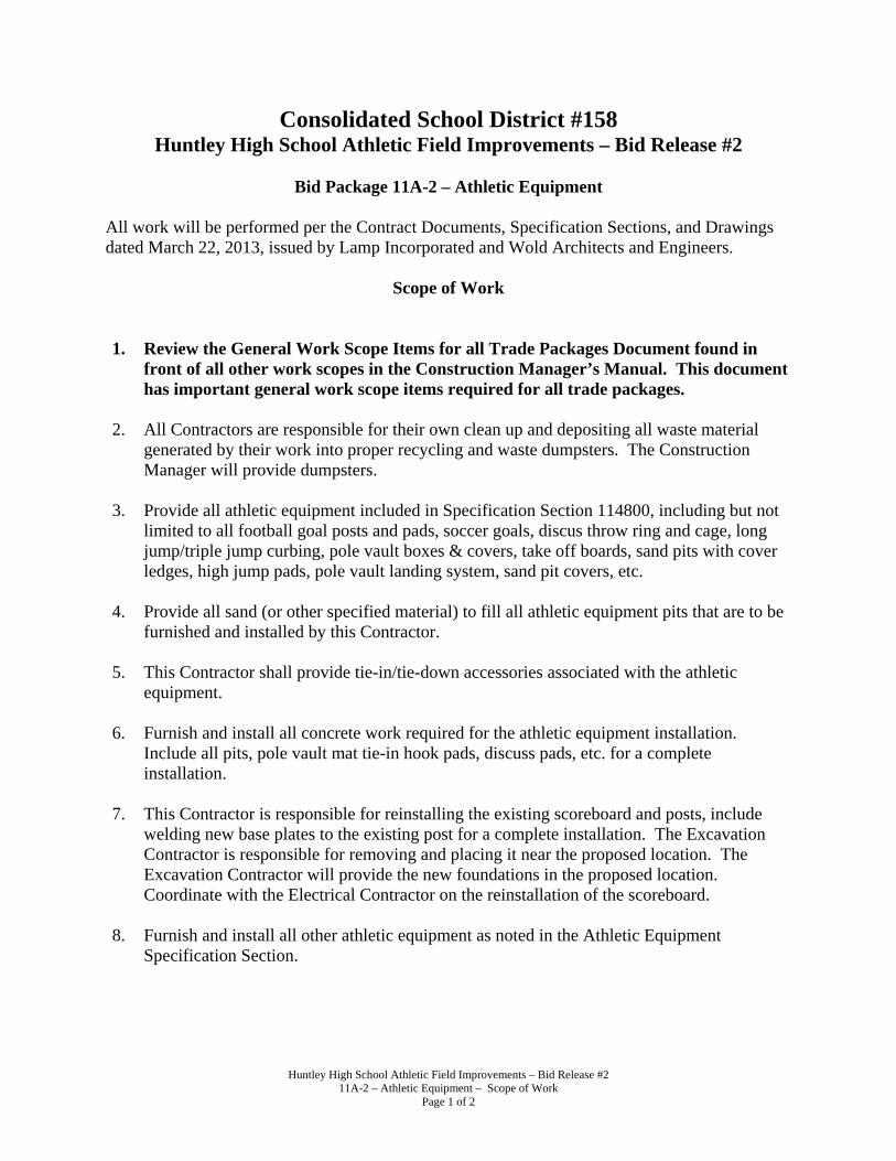
Huntley High School Athletic Field Improvements – Bid Release #2 11A-2 – Athletic Equipment – Scope of Work
Page 1 of 2
Consolidated School District #158 Huntley High School Athletic Field Improvements – Bid Release #2
Bid Package 11A-2 – Athletic Equipment
All work will be performed per the Contract Documents, Specification Sections, and Drawings dated March 22, 2013, issued by Lamp Incorporated and Wold Architects and Engineers.
Scope of Work
1. Review the General Work Scope Items for all Trade Packages Document found in
front of all other work scopes in the Construction Manager’s Manual. This document has important general work scope items required for all trade packages.
2. All Contractors are responsible for their own clean up and depositing all waste material
generated by their work into proper recycling and waste dumpsters. The Construction Manager will provide dumpsters.
3. Provide all athletic equipment included in Specification Section 114800, including but not limited to all football goal posts and pads, soccer goals, discus throw ring and cage, long jump/triple jump curbing, pole vault boxes & covers, take off boards, sand pits with cover ledges, high jump pads, pole vault landing system, sand pit covers, etc.
4. Provide all sand (or other specified material) to fill all athletic equipment pits that are to be furnished and installed by this Contractor.
5. This Contractor shall provide tie-in/tie-down accessories associated with the athletic equipment.
6. Furnish and install all concrete work required for the athletic equipment installation.
Include all pits, pole vault mat tie-in hook pads, discuss pads, etc. for a complete installation.
7. This Contractor is responsible for reinstalling the existing scoreboard and posts, include
welding new base plates to the existing post for a complete installation. The Excavation Contractor is responsible for removing and placing it near the proposed location. The Excavation Contractor will provide the new foundations in the proposed location. Coordinate with the Electrical Contractor on the reinstallation of the scoreboard.
8. Furnish and install all other athletic equipment as noted in the Athletic Equipment
Specification Section.

Huntley High School Athletic Field Improvements – Bid Release #2 11A-2 – Athletic Equipment – Scope of Work
Page 2 of 2
ALTERNATES: - None
UNIT PRICES: All unit prices are to include labor, material, equipment, freight, unloading, storage, labor benefits, insurance, testing, inspections, shop drawings, and Contractor’s overhead and profit to install the material in its final location. Unit prices will only be used to determine Change Order items requested by the Construction Manager or charging against a previously determined allowance. Unit prices shall not be used by the Trade Contractor to claim additional monies for work that was originally shown in the Contract Documents. Unit Prices shall be used for both adding and deleting work. UP-SE1: Football/Soccer Goal System: Provide a unit cost in dollars per each ($/EA) to furnish
and install a Football/Soccer Goal System according to the Contract Documents. UP-SE2: Vault Box: Provide a unit cost in dollars per each ($/EA) to furnish and install a Vault
Box according to the Contract Documents.
UP-SE3: Pole Vault Landing System: Provide a unit cost in dollars per each ($/EA) to furnish and install a Pole Vault Landing System according to the Contract Documents.
Work or services included in other Trade Packages or by the Construction Manager, unless otherwise noted above. 1. Scoreboard Foundation.

Huntley High School Athletic Field Improvements – Bid Release #2 16A-2 – Electrical – Scope of Work
Page 1 of 3
Consolidated School District #158 Huntley High School Athletic Field Improvements – Bid Release #2
Bid Package 16A-2 – Electrical
All work will be performed per the Contract Documents, Specification Sections, and Drawings dated March 22, 2013, issued by Lamp Incorporated and Wold Architects and Engineers.
Scope of Work
1. Review the General Work Scope Items for all Trade Packages Document found in front of all other work scopes in the Construction Manager’s Manual. This document has important general work scope items required for all trade packages.
2. All Contractors are responsible for their own clean up and depositing all waste material
generated by their work into proper recycling and waste dumpsters. The Construction Manager will provide dumpsters.
3. This Contractor is required to attend any coordination meetings to avoid any installation
conflicts. Provide electronic files for overlay of routing with other Contractors. Final coordination drawings will be approved by all Contractors to ensure proper installation of all materials.
4. Progressive as-builts need to be reviewed by the General Contractor at 33% and 67% completion for each system; payments may be withheld until this has been completed.
5. This Contractor is responsible for cutting power to all necessary items that are scheduled to
be removed by Others. This includes, but is not limited to the existing press box and scoreboard.
6. Provide all electrical work shown on the Electrical Drawings. Including but not limited to
all raceways, handholes, low voltage, and power wiring. 7. This Contractor is responsible for providing power and control wiring to the relocated
scoreboard. 8. This Contractor is responsible for providing power, new transformer, and low voltage to the
new press box. A main feeder stub will be provided at an accessible location from the pressbox. Pull all wiring and include connection to the panel provided in proposed pressbox. All electrical work within the new press box will be by Others.
9. Furnish and install all exterior light fixtures underneath the proposed bleachers. Install the
lighting control system on circuits as required by the Contract Documents.
10. Furnish and install meter panels, breaker panels, etc. to provide a complete electric service.

Huntley High School Athletic Field Improvements – Bid Release #2 16A-2 – Electrical – Scope of Work
Page 2 of 3
11. This Contractor is to provide all trenching and exaction as required to complete their work. All excavations shall be backfilled with properly compacted granular fill. Provide concrete encasement for all conduits and services that require it. All excavated spoils generated by this Trade Contractor shall be hauled to a location designated by the Construction Manager.
12. This Contractor is responsible for their own sawcutting of the concrete slab and coring through the existing foundations as required by the Contract Documents. Include all patching as necessary.
13. All penetrations through existing walls, floors, and ceilings that are required by this
Contractor’s scope of work will be their responsibility to properly install, reinforce, maintain the required fire rating, support, and return the existing surface to its original condition. All penetrations removed by this Contractor and not replaced shall be properly patched and sealed by this Contractor.
14. Perform all electrical demolition work as required by the Contract Documents. All
demolished material that cannot be recycled shall be placed in dumpsters provided by the Electrical Contractor. This Contractor shall also include all necessary cutting and patching to restore all walls, floors, and ceilings to their original condition. Recycle all material possible. All fluorescent tubes and ballasts will be disposed of properly by the Electrical Contractor and will not be allowed in the dumpsters provided by the Construction Manager.
15. This Contractor is responsible for removing and patching existing floor, wall, and ceiling
surfaces not shown on the drawings to be removed and/or replaced but is required to perform their Scope of Work.
16. Label all panel boards properly so the Owner knows which circuit controls which piece of
electrical equipment. All identification cards in the panel boxes will be typed or computer printed. Hand written identification will be unacceptable.
17. This Contractor is required to remove any temporary markings from all installed materials
which will remain exposed. ALTERNATES:
Alternate #1 – Feeder Conductors Replacement – Provide additional cost to replace the existing four (4) 100a, 480v, 3∅ feeder conductors (run in the existing raceway) from the poles to the amenities building.
Alternate #2 – New Underground Feeder – Provide additional cost for a new underground feeder from each football field lighting pole (4 total) of 4 #3 & 1#6 grd, 1-1/4" c. to the 100a,3p breakers in existing panel ab-1, via the new 100a,3p lighting contactors.

Huntley High School Athletic Field Improvements – Bid Release #2 16A-2 – Electrical – Scope of Work
Page 3 of 3
UNIT PRICES: All unit prices are to include labor, material, equipment, freight, unloading, storage, labor benefits, insurance, testing, inspections, shop drawings, and Contractor’s overhead and profit to install the material in its final location. Unit prices will only be used to determine Change Order items requested by the Construction Manager or charging against a previously determined allowance. Unit prices shall not be used by the Trade Contractor to claim additional monies for work that was originally shown in the Contract Documents. Unit Prices shall be used for both adding and deleting work. UP-E1: 2” Plastic Raceway: Provide a unit cost in dollars per lineal foot ($/LF) to furnish and
install a 2” plastic raceway installed at a typical depth according to the Contract Documents.
UP-E2: Handhole: Provide a unit cost in dollars per each ($/EA) to furnish and install an
electrical handhole according to the Contract Documents.

Huntley High School Athletic Field Improvements – Bid Release #2 Public Bidding Certificates – Page 1 of 2
PUBLIC BIDDING CERTIFICATES
The following are owner’s certification requirements which must be signed and submitted by all persons submitting a bid for this project. Any bid submitted without this attachment properly signed by the bidder may be rejected as non-responsive. These certifications of the successful bidder will be incorporated into and made a part of the contract for the project. The undersigned, , hereby certifies, affirms and agrees as part of its bid for the work for Huntley High School Athletic Field Improvements – Bid Release #2, Huntley, Illinois for Board of Education of Consolidated School District 158, Algonquin, Illinois, as follows:
1. CERTIFICATE OF BIDDER ELIGIBILITY Contractor is not barred from bidding on public contracts due to bid rigging of bid rotation as a result of a violation of either 720 ILCS 5/33E-3 or 720 ILCS 5/33-E4 as required by 720 ILCS 5/33E-11.
2. CERTIFICATE OF COMPLIANCE WITH ILLINOIS DRUG-FREE WORKPLACE ACT If Contractor has 25 or more employees, Contractor does hereby certify pursuant to section 3 of the Illinois Drug-Free Workplace Act (30 ILCS 580/3) that it shall provide a drug-free workplace for all employees engaged in the performance of work under the contract by complying with the requirements of the Illinois Drug-Free Workplace Act and, further certifies that it is not ineligible for award of this contract by reason of debarment for a violation of the Illinois Drug-Free Workplace Act.
3. CERTIFICATE REGARDING SEXUAL HARASSMENT POLICY Contractor hereby represents, warrants and certifies that no officer or director of contractor has any knowledge that any employee thereof has been convicted of committing or attempting to commit any one or more of the following offenses set forth in Section 5/21-23a of the Illinois School Code or who falsifies, or omits facts from his or her employment documents.
Contractor agrees that it shall not employ any person who has or may have direct, daily contact with the pupils of any school in the district, and for whom a criminal background investigation has not been conducted pursuant hereto, and further represents and agrees that all employees or applicants who may have direct contract with employees shall be required to furnish a written “Authorization for Criminal Background Information” on forms provided by the district authorizing the Board of Education to request a criminal background investigation of said person pursuant to 105 ILCS 5/10-21-9 as amended by P.A. 96-1452 and to receive criminal history record information pursuant thereto to determine if the applicant has been convicted of committing or attempting to commit any of the criminal or drug offenses enumerated above. Contractor further agrees to submit with said authorization for any costs and expenses associated with the criminal background investigation.
Contractor further represents, warrants and certifies that no employee or applicant with respect to whom the criminal investigation reveals any conviction for committing and/or attempting to commit any of the above enumerated offenses, including the Sex Offender Registry Act, and the Statewide Child Murder and Violent Offender Against Youth Database shall be employed thereby in any position that involves or may involve contact with the students of the school district.
4. CERTIFICATE REGARDING EQUAL EMPLOYMENT OPPORTUNITY Contractor certifies, pursuant to Section 2-105 of the Illinois Human Rights Act (775 ILCS 5/2-105) that it has a written equal employment opportunity policy that is in compliance with all terms and conditions of the Equal Employment Opportunity provisions of the Illinois Human Rights Act.

Huntley High School Athletic Field Improvements – Bid Release #2 Public Bidding Certificates – Page 2 of 2
5. CERTIFICATE REGARDING EMPLOYMENT OF ILLINOIS WORKERS ON PUBLIC WORKS Contractor agrees if at the time the Agreement is executed, or if during the term of the Agreement, there is excessive unemployment in Illinois as defined in the Employment of Illinois Workers on Public Works Act, 30 ILCS 570/0/01 et seq., as two consecutive months of unemployment exceeding 5%, then Contractor agrees to employ Illinois laborers in accordance with the Employment of Illinois Workers on Public Works Act. An “Illinois laborer” is defined as any person who has resided in Illinois for at least thirty (30) days and intends to become or remain an Illinois resident. 6. PREVAILING WAGE AFFIDAVIT AFFIDAVIT: “I (we) hereby certify and affirm that if awarded a contract with Consolidated School District 158, we will comply fully with the “Illinois Prevailing Wage Act, 820 ILCS 130/.01 et seq. (“the Act”)”. We further understand that current prevailing wage standards are included in the Project Manual.” All contractors and subcontractors rendering services under this contract must comply with all requirements of the Act, including but not limited to, all wage, notice and record keeping duties.
Contractor certifies that said contractor is not barred from bidding on the aforementioned contract as a result of a violation of “Illinois Prevailing Wage Act, 820 ILCS 130/.01 et seq. (“the Act”)”.
7. NON-COLLUSION AFFIDAVIT AFFIDAVIT: “I (we) hereby certify and affirm that my (our) proposal was prepared independently for this project and that it contains no fees or amounts other than that for the legitimate execution of this work as specified and that it includes no understanding or agreements in restraint of trade.”
Contractor certifies that said Contractor is not barred from bidding on the aforementioned contract as a result of a violation of the above Non-Collusion Affidavit.
Firm: __________________________
By: ____________________________
(Signature)
____________________________
(Printed Name & Title)
SUBSCRIBED and SWORN TO before me
This _________________ day of _______________, 2013.
___________________________________
NOTARY PUBLIC

Project Name Date From:
Company Date To:
Union Local No.
Labor Classification
REGULAR TIME AND 1/2 DOUBLE TIME
FICA @ % of Base _7.65_ %
Sub-Total
Adjusted Workmen's Comp.*
Federal and State Unemployment Insurance $0.75 (This amount cannot be changed)
Sub-Total
Total Rate/Hour
Workmen's Comp. Code _______
Workmen's Comp. Premium Rate _____
OTHER COSTS
EMR _______
Overhead and profit rates will be applied as described in the Contract Documents
Situation when Time and 1/2 Occurs
Situation when Double Time Occurs
Union Benefits per published union ratesBase Rate per published union rates
Huntley High School Athletic Field Improvements - Bid Release #2
If Prime Trade Contactor has more than one classification of Labor, submit a rate sheet of each one.
Labor Rate Sheet

Huntley High School Athletic Field Improvements – Bid Release #2 Criminal Background Investigation – Page 1 of 1
CRIMINAL BACKGROUND INVESTIGATION Bidder acknowledges that if its bid is accepted, any employees working on district property must submit to a criminal background check performed by the school. The costs of such background checks will be paid by Bidder. No employee or other representative of the Bidder shall be permitted to be present on district property until the district’s receipt of the criminal background check report which is acceptable to district in its sole discretion. Bidder shall insure that any contracts with subcontractors working on district property include this same provision to insure that employees of subcontractors are obligated to undertake criminal background checks and that the district has the discretion to prohibit the employees of such subcontractors from district property based upon the information contained in the criminal background check reports. This certification is executed on the date hereinafter indicated by the designated contractor by its duly authorized officer.
By
Its:
Dated:

Huntley High School Athletic Field Improvements – Bid Release #2 List of Subcontractors/Suppliers - Page 1 of 1
CONSOLIDATED SCHOOL DISTRICT 158 Huntley High School Athletic Field Improvements –
Bid Release #2
LIST OF SUBCONTRACTORS/SUPPLIERS
Bidder _________________________ Trade Package ________ In the spaces provided below, indicate Subcontractors that this Trade Contractor will contract with, for work required by the Contract Documents, which will not be performed by this Trade Contractor’s own forces. Also include all major equipment and material suppliers. *Include this form with the Proposal Form. SUBCONTRACTOR/SUPPLIER TRADE
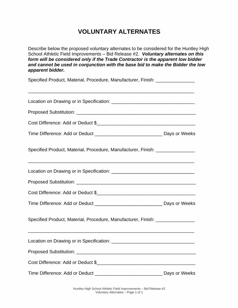
Huntley High School Athletic Field Improvements – Bid Release #2 Voluntary Alternates – Page 1 of 1
VOLUNTARY ALTERNATES Describe below the proposed voluntary alternates to be considered for the Huntley High School Athletic Field Improvements – Bid Release #2. Voluntary alternates on this form will be considered only if the Trade Contractor is the apparent low bidder and cannot be used in conjunction with the base bid to make the Bidder the low apparent bidder. Specified Product, Material, Procedure, Manufacturer, Finish: _______________ ________________________________________________________________ Location on Drawing or in Specification: ________________________________ Proposed Substitution: ______________________________________________ Cost Difference: Add or Deduct $______________________________________ Time Difference: Add or Deduct __________________________ Days or Weeks Specified Product, Material, Procedure, Manufacturer, Finish: _______________ ________________________________________________________________ Location on Drawing or in Specification: ________________________________ Proposed Substitution: ______________________________________________ Cost Difference: Add or Deduct $______________________________________ Time Difference: Add or Deduct __________________________ Days or Weeks Specified Product, Material, Procedure, Manufacturer, Finish: _______________ ________________________________________________________________ Location on Drawing or in Specification: ________________________________ Proposed Substitution: ______________________________________________ Cost Difference: Add or Deduct $______________________________________ Time Difference: Add or Deduct __________________________ Days or Weeks

Huntley High School Athletic Field Improvements – Bid Release #2 Bid Day Label – Page 1 of 1
BID DAY LABEL
Please cut out this box and tape to your envelope for your mailing label
Please cut out the box below and tape it to the lower left hand corner of your bid envelope.
Huntley High School Athletic Field Improvements
Bid Release #2 Trade Package Name – _________________________ Pkg #______
This Bid is being submitted by:
(Name of Contractor submitting bid)
A complete bid includes all of the following: please check each box to indicate that you have included these items. FAILURE TO INCLUDE ANY OF THESE ITEMS MAY RESULT IN THE REJECTION OF YOUR BID!
Bid Form – 2 Copies (all addenda acknowledged?) Bid Bond – 2 Copies (or 1 copy of Certified Check) Compliance Certification and Substance Abuse – 2 Copies Compliance Criminal Background Investigation – 2 Copies Labor Rate Sheet for each Labor Classification – 2 Copies
(Note – these are separate from the Unit Prices on the bid form)
Qualification forms should not be included in this envelope – they were due previously to Lamp Inc.
Sealed bid – DO NOT OPEN!! Attn: Dr. John Burkey Superintendent of Schools Consolidated School District 158 Administration Office 650 Academic Drive Algonquin, IL 60120


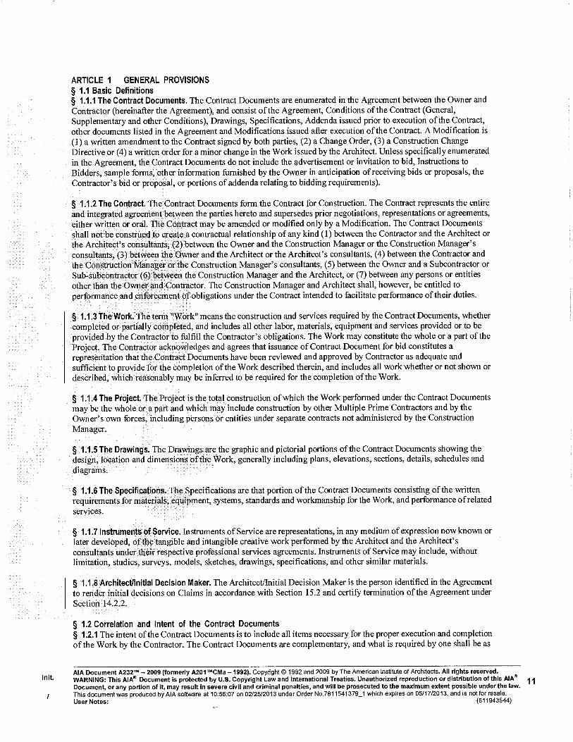


Huntley High School Athletic Field Improvements – Bid Release #2 Pay Request Form – Page 1 of 1
PAY REQUEST FORM
Applications for payment shall be made on AIA form G702 with appropriate breakdown on AIA form G703. Company invoices will not be acceptable and lump sum dollar amounts on the standard forms will also not be acceptable. The Trade Contractors pay request shall be broken down on AIA form G703 to show major portions of the work and locations if the contract is large enough. Prior to the first request for payment, the Trade Contractor shall submit a breakdown of values for review by the Construction Manager, Architect, and Owner. Partial and Final Waivers shall be submitted and Chicago Title Waiver Forms or approved equals.

Textura™ Construction Invoicing & Payment Solution: Work Faster and More Efficiently
What Is Textura™?
Textura™ is an Internet-based construction invoicing and payment solution. With the Textura™ system,
subcontractors can electronically sign and submit their pay applications—including invoices, sworn
statements, and conditional and/or unconditional lien waivers. Payments are made electronically via ACH
(Automated Clearing House) resulting in faster access to your funds. In addition, Textura™ facilitates
submission and tracking of compliance documents and sub-tier lien waivers. In short, Textura™ has
revolutionized the construction payment process. Thousands of subcontractors currently use Textura™ to
submit their pay applications every month.
Sign Pay Applications and Submit Electronically
Textura™ automatically generates the required Pay Application documents and transmits them to your GC
electronically at the click of a button.
Invoices are created by simply entering a % complete or $ value by line item of your budget.
Electronic submission of documents eliminates the expense and inconvenience of fax or hand delivery.
Invoice amounts are verified with lien waiver and payment amounts, reducing the risk of error.
Receive Payments via ACH
Textura™ uses the secure ACH network for electronic deposit of funds to accelerate the payment process.
ACH will deliver funds faster than a manual check. Payments are made through Textura™ directly by
your GC and are subject to the terms of your contract.
ACH payments work like direct deposit—funds are immediately available, no waiting for check to clear.
Textura™ alerts you via email that payment has been disbursed.
Know What is Happening, When It Happens
Textura™ offers users complete visibility throughout the draw process and notifies users of critical events.
Receive real-time notifications when a draw is opened, change order issued, payment disbursed, etc.
Receive email reminders to update expiring insurance documents and notification of non-compliance.
Online invoice approval and rejection ensures that both parties are informed of final invoice amounts.
Manage Documents Online
Project documents created in or uploaded to the system are available for viewing, printing or downloading
to your computer. Textura™ will store these documents for a minimum of seven years.
Pay Application backup documents are submitted quickly and easily via an upload attachment feature.
Electronic submission and tracking of legal documents such as insurance certificates reduces payment holds.
Possibility for lost or delayed documents and resulting held payments virtually eliminated.
What Does It Cost to Use Textura™?
Technical Requirements:
The Textura™ application is completely web-based—
there is no software to install. Users need only:
Internet access (high-speed recommended)
Email address for each user
Adobe Acrobat Reader 6.0 or higher(free download)
Free Training & Support:
Textura™ supports your training needs with:
Computer-Based Training (CBT) modules.
Free webinars available through Textura’s website.
Individual training by phone.
Classroom training where available
Support representatives are available to answer your
questions at 866-TEXTURA (866-839-8872).
One-time fee at the start of contract:
0.15% of contract value.
o Minimum – $50.
o Maximum – $1,450.
o Sub-tier subcontractors – $50.
There are no additional fees for subscription, licenses, training, or call center support. See Textura™ Terms & Conditions for more information.
For information on how to get started, please call 866-TEXTURA (866-839-8872) or visit the Textura™ website at www.texturacorp.com


Huntley High School Athletic Field Improvements – Bid Release #2 011000 SUMMARY OF WORK
Page 1 of 3
SECTION 011000 - SUMMARY OF WORK PART 1 - GENERAL
1.01. RELATED DOCUMENTS A. Drawings and general provisions of Contract, including General and
Supplementary Conditions and other Division-1 Specification Sections, apply to this Section.
1.02. SUMMARY A. This Section includes the following:
1. Project Information 2. Work covered by the Contract Documents 3. Work under other contracts 4. Use of premises 5. Owner’s occupancy requirements 6. Work Restrictions
B. Related Sections include the following: 1. Division 01 Section “Temporary Facilities” for limitations and procedures
governing temporary use of the Owner’s Facilities 2. “General Work Scopes for All Trade Contractors” found in the Project
Manual, for project specific instructions applying to multiple Trade Contractors.
1.03. PROJECT INFORMATION A. Project Identification: Huntley High School Athletic Field Improvements – Bid
Release #2 1. Project Location: Huntley High School, 13719 Harmony Road, Huntley,
IL 60142 B. Owner: Board of Education of Consolidated School District 158, 650
Academic Drive, Algonquin, IL 60102 C. Architect: Wold Architects and Engineers, 110 North Brockway Street, Two
Hundred Twenty, Palatine, IL 60067 D. Construction Manager: Lamp Incorporated, 460 North Grove Avenue, Elgin,
IL 60120. 1. Preconstruction Contact: Tom McGrath at [email protected] 2. Obtaining bid documents, insurance, bonding, and procedural questions
contact Mary Comiskey at [email protected]
1.04. WORK COVERED BY CONTRACT DOCUMENTS A. The Work of Project is defined by the Contract Documents and consists of
the following: 1. The Work includes replacement of the existing athletic field with new
synthetic turf and storm water drainage system, reconstruction and resurfacing of the existing track sruface, new athletic equipment, new fencing and associated site improvements.
B. Type of Contract

Huntley High School Athletic Field Improvements – Bid Release #2 011000 SUMMARY OF WORK
Page 2 of 3
1. Project will be construction under coordinate, concurrent multiple contracts to be held by the Owner. Refer to the Construction Manager’s Manual for a description of work for each individual trade package.
1.05. WORK UNDER OTHER CONTRACTS A. General: The Owner may award separate contracts for additional work to be
performed at the site during construction. Cooperate fully with separate contractors so that work on those contracts may be carried out smoothly, without interfering with or delaying work under this Contract. Coordinate the work of this Contract with work performed under separate contracts.
1.06. CONTRACTOR USE OF PREMISES A. General: During the construction period the Trade Contractor shall have full
use of the work area for construction operations, including use of the site. The Trade Contractor’s use of the premises is limited only by the Owner’s right to perform construction operations with its own forces or to employee separate contractors on portions of the project.
B. Confine operations at site to areas permitted by 1. Permits. 2. Contract Documents.
C. Do not unreasonably encumber site with materials or equipment. D. Assume full responsibility for protection and safekeeping of materials, tools,
equipment and products stored on premises. E. Move any stored products which interfere with operations of Owner or other
Contractor. F. Obtain and pay for use of additional storage or work areas needed for
operations. G. Provide all pumping necessary to keep site utility lines and excavations free
from water. Do not discharge water on adjoining property. H. Clean-up work area at the close of each day.
1.07. PRE-ORDERED PRODUCTS A. General: The Construction Manager may negotiate purchase orders with
suppliers of material and equipment to be incorporated into the Work. These purchase orders are assigned to the Trade Contractor and costs for receiving, handling, storage, if required, and installation are included in the Contract sum.
B. The Trade Contractor’s responsibilities are the same as if he negotiated purchase orders, including responsibility to renegotiate purchase if necessary and to execute final purchase order agreements
1.08. GENERAL PROVISIONS A. Give required notices. B. Comply with codes, ordinances, rules, regulations, orders, and other legal
requirements of public authorities, which bear on performance of work. C. Promptly submit written notices to Architect, of observed variance of
Contract Documents from legal requirements. D. Maintain regular traffic flow around site and within building unless otherwise
directed.

Huntley High School Athletic Field Improvements – Bid Release #2 011000 SUMMARY OF WORK
Page 3 of 3
E. Repair any damage to property which is to remain in use, or that belongs to any person, or persons, on or off the site, caused by construction.
F. Perform all work in such a manner as to prevent fires. Remove debris promptly; do not burn materials on the site.
G. Keep stairways and exits unobstructed and available for use at all times. H. Protect and maintain existing utility lines in such a manner as to prevent
interruptions of service. I. Cap all utility lines terminated by work on this project in a manner approved
by governmental and utility authorities having jurisdiction. J. Remove all materials from construction operations in such a manner as to
avoid creating a nuisance. Legally dispose of all materials on a daily basis. K. All Contractors installing underground utilities shall place alarm tape 12
inches below the surface during trench backfill. L. All Contractors shall be responsible for street sweeping if trucks or
equipment used during their operations cause mud deposits on streets. M. All Contractors making floor or wall penetrations for their work shall include
firesafing materials to properly seal their penetrations. N. Any penetrations through walls exposed to view shall be patched and
caulked to a smooth surface ready to be painted, or sealed by trade responsible for such penetrations.
O. All Contractors shall inspect surfaces, structure and other work precedent to their work and upon which their work depends, and verify that no defects or errors are present that could result in poor application in their work or cause latent defects in workmanship.
P. Any defects or errors found in work precedent to another Contractor’s operations shall be reported to the Construction Manager, who shall see that such are corrected prior to commencement of work by the contractor affected.
Q. Commencement of any operation shall constitute acceptance of substrates or preceding work by the contractor performing same.
R. Each Contractor shall adequately prepare substrates or preceding work prior to commencing their installation operations.
S. All manufactured articles, materials, appliances and equipment shall be applied, installed, connected, erected, used, clean conditioned, and placed in operation as directed by the respective manufacturer, insofar as these directions are applicable to this particular project and are not in conflict with superior requirements in the specifications or requirements of applicable Building Codes.
T. Provide all pumping necessary to keep site utility lines and excavations free from water. Do not discharge water on adjoining property. Reference individual work scopes for specific pumping requirements.
PART 2 - PRODUCTS (Not applicable). PART 3 - EXECUTION (Not applicable)
END OF SECTION 011000

Huntley High School Athletic Field Improvements – Bid Release #2 012100 ALLOWANCES
Page 1 of 3
SECTION 012100 - ALLOWANCES PART 1 - GENERAL 1.01. RELATED DOCUMENTS
A. Drawings and general provisions of Contract, including General and Supplementary
Conditions and Division 1 Specification Sections, apply to this Section. 1.02. SUMMARY
A. This Section specifies administrative and procedural requirements governing handling and processing allowances.
1. Selected materials, equipment, and in some cases labor, are shown and/or
specified in the Contract Documents by allowances. Unforeseen and unknown conditions are also specified in the Contract Documents. Allowances have been established in lieu of additional requirements, or to defer selection of actual materials and equipment to a later date when additional information is available for evaluation. Additional requirements, if necessary, will be issued by Change Order.
2. Allowances as listed in the Contract Documents are for the purchase, delivery, installation, and all other necessary costs to perform the work as described in the allowance. Contractor’s overhead and profit are NOT to be included in allowances. Overhead and profit for allowances should be included in the Contractor’s overhead and profit for the entire project.
B. Types of allowances required include the following:
1. Lump sum allowances – typically listed in the Trade Contractor’s Scope of
Work, and listed on the bid form as a separate cost to be added to the base bid.
2. Unit-cost allowances – typically listed in the specifications and drawings – to be used to calculate base bid costs.
3. Quantity allowances – typically listed in the specifications and drawings – to be
used to calculate base bid costs.
C. Procedures for submitting and handling Change Orders are included in Section 012600 “Contract Modification Procedures.”
1.03. SELECTION AND PURCHASE
A. At the earliest feasible date after Contract award, advise the Architect and the Construction Manger of the date when the final selection and purchase of each product or system described by an allowance must be completed in order to avoid delay in performance of the Work.

Huntley High School Athletic Field Improvements – Bid Release #2 012100 ALLOWANCES
Page 2 of 3
B. When requested by the Architect or the Construction Manager, obtain proposals for each allowance for use in making final selections; include recommendations that are relevant to performance of the Work.
C. Purchase products and systems as selected by the Architect from the designated
supplier. 1.04. SUBMITTALS
A. Submit proposals for purchase of products or systems included in allowances, in the form specified for Change Orders.
B. Submit invoices or delivery slips to indicate actual quantities of materials delivered
to the site for use in fulfillment of each allowance.
C. Submit time sheets verified by the Construction Manger’s on-site superintendent verifying hours worked to complete the allowance work.
1.05. UNUSED MATERIALS
A. Return unused materials to the manufacturer or supplier for credit to the Owner, after installation has been completed and accepted.
B. Where it is not economically feasible to return unused material for credit and when
requested by the Architect, prepare unused material for the Owner’s storage, and deliver to the Owner’s storage space as directed. Otherwise, proper disposal of excess material is the Contractor’s responsibility.
PART 2 - PRODUCTS (Not Applicable) PART 3 - EXECUTION 3.01. SUMMARY:
A. Upon selection and approval of the material to be purchased by the allowance, the
Contractor shall purchase the material in an efficient manner as to not delay the project schedule.
3.02. INSPECTION
A. Inspect products covered by an allowance promptly upon delivery for damage or defects
3.03. PREPARATION
A. Coordination materials and their installation for each allowance with related materials and installations to ensure that each allowance item is completely integrated and interfaced with related construction activities.
3.04. SCHEDULE OF ALLOWANCES

Huntley High School Athletic Field Improvements – Bid Release #2 012100 ALLOWANCES
Page 3 of 3
A. Refer to project manual – Lump sum allowances have been inserted into the work scopes to which they apply.
B. Refer to project specifications and drawings – allowances have been included for materials, labor, and equipment.
C. Refer to Addenda issued during bidding process, which may add, change, or delete
allowances.
END OF SECTION 012100

Huntley High School Athletic Field Improvements – Bid Release #2 012200 UNIT PRICES
Page 1 of 2
SECTION 012200 - UNIT PRICES
PART 1 - GENERAL
1.01. RELATED DOCUMENTS
A. Drawings and general provisions of the Contract, including General and Supplementary Conditions and other Division 01 Specification Sections, apply to this Section.
1.02. SUMMARY
A. This Section includes administrative and procedural requirements for unit prices.
B. Related Sections include the following:
1. Division 01 Section "Allowances" for procedures for using unit prices to adjust quantity allowances.
2. Division 01 Section "Contract Modification Procedures" for procedures for submitting and handling Change Orders.
3. Divisions 02 through 49 Sections for items of Work covered by unit costs.
C. Refer to “Construction Manager’s Manual” for additional information.
1.03. DEFINITIONS
A. Unit price is an amount proposed by bidders, stated on the Bid Form, as a price per unit of measurement for materials, equipment, or services added to or deducted from the Contract Sum by appropriate modification, if the Scope of Work or estimated quantities of Work required by the Contract Documents are increased or decreased.
1.04. PROCEDURES
A. Unit prices include all necessary material, plus cost for delivery, installation, insurance, applicable taxes, overhead, and profit.
B. Measurement and Payment: Refer to individual Specification Sections for work that requires establishment of unit prices. Methods of measurement and payment for unit prices are specified in those Sections.

Huntley High School Athletic Field Improvements – Bid Release #2 012200 UNIT PRICES
Page 2 of 2
C. Owner reserves the right to reject Contractor's measurement of work-in-place that involves use of established unit prices and to have this work measured, at Owner's expense, by an independent surveyor acceptable to Contractor.
PART 2 - PRODUCTS (Not Used)
PART 3 - EXECUTION
3.01. LIST OF UNIT PRICES
A. Refer to the Construction Manager’s Scope of Work for Unit Costs included in each Trade Package.
END OF SECTION 012200
Huntley High School Athletic Field Improvements – Bid Release #2 012300 ALTERNATES
Page 1 of 2
SECTION 012300 - ALTERNATES PART 1 - GENERAL 1.01. RELATED DOCUMENTS
A. Drawings and general provisions of Contract, including General and Supplementary Conditions and other Division-1 Specification Sections, apply to this Section.
1.02. SUMMARY
A. This Section specifies administrative and procedural requirements for Alternates. 1.03. DEFINITION
A. An Alternate is an amount proposed by Bidders and stated on the Proposal Form for certain construction activities defined in the Bidding Requirements that may be added to or deducted from Base Bid amount if the Owner decides to accept a corresponding change in either the amount of construction to be completed, or in the products, materials, equipment, systems or installation methods described in Contract Documents.
1.04. COORDINATION
A. Coordinate related Work and modify or adjust adjacent Work as necessary to ensure that Work affected by each accepted Alternate is complete and fully integrated into the project.
1.05. NOTIFICATION
A. Immediately following the award of the Contract, prepare and distribute to each party involved, notification of the status of each Alternate. Indicate whether Alternates have been accepted, rejected or deferred for consideration at a later date. Include a complete description of negotiated modifications to Alternates.
1.06. SCHEDULE
A. A “Schedule of Alternates” is included at the end of this Section. Specification Sections referenced in the Schedule contain requirements for materials and methods necessary to achieve the Work described under each Alternate.
B. Include as part of each Alternate, miscellaneous devices, accessory objects and
similar items incidental to or required for a complete installation whether or not mentioned as part of the Alternate.
C. Trade Contractors’ responsibilities will be spelled out for each Alternate in their
scope of work. If an alternate is not listed in the Trade Contractor’s scope of work it is felt by the Construction Manager as not applicable to this particular Trade Package. If a Trade Contractor feels the Alternate does in fact affect their costs they should notify the Construction Manager immediately so that this can be addressed in their scope of work and on the bid form.
PART 2 - PRODUCTS (Not Applicable).

Huntley High School Athletic Field Improvements – Bid Release #2 012300 ALTERNATES
Page 2 of 2
PART 3 - EXECUTION 3.01. SCHEDULE OF ALTERNATES
1. Alternate #1 – Feeder Conductors Replacement – Provide additional cost to replace the existing four (4) 100a, 480v, 3∅ feeder conductors (run in the existing raceway) from the poles to the amenities building.
2. Alternate #2 – New Underground Feeder – Provide additional cost for a new underground feeder from each football field lighting pole (4 total) of 4 #3 & 1#6 grd, 1-1/4" c. to the 100a,3p breakers in existing panel ab-1, via the new 100a,3p lighting contactors.
3. Alternate #3 – Safewater Hydrants – Provide additional cost for the new Safewater Hydrants according to the Contract Documents. Include all work required in the amenities building, floor slab cutting and patching, asphalt removal, water service pipe, fittings, insulation, and connections as required for a complete system. Refer to Civil and Architectural Sheets for details and work associated with this alternate.
END OF SECTION 012300

Huntley High School Athletic Field Improvements – Bid Release #2 012600 CONTRACT MODIFICATION PROCEDURES
Page 1 of 4
SECTION 012600 - MODIFICATION PROCEDURES PART 1 - GENERAL
1.01 RELATED DOCUMENTS
A. Drawings and general provisions of Contract, including General and Supplementary Conditions and other Division-1 Specification Sections, apply to this Section.
B. Contractor Labor Rate form submitted with their bid will be used for applying change in labor costs. This rate can only include the cost of Labor, exclusive of material, equipment, vehicle, profit, or other overhead costs – these values will be assessed to each change order separate of the labor rate, as they apply to each proposed change.
1.02 SUMMARY
A. This Section specifies administrative and procedural requirements for
handling and processing Contract modifications (Change Orders).
1. Multiple Prime Contracts: Provisions of this Section apply to the Work of each prime contractor.
2. Related Sections: The following sections contain requirements that relate to this section.
3. Division 1 Section “Allowances” for procedural requirements governing the handling processing of allowances.
4. Division 1 Section “Application for Payment” for administrative procedures governing applications for payment.
1.03 MINOR CHANGES IN THE WORK
A. Supplementary instructions authorizing minor changes in the Work, not
involving an adjustment to the Contract Sum or Contract Time, will be issued by the Construction Manager.
1.04 CHANGE ORDER PROPOSAL REQUESTS
A. Owner Initiated Proposal Requests: Proposed changes in the Work that will
require adjustment to the Contract Sum or Contract Time will be issued by the Architect through the Construction Manager, with a detailed description of the proposed change and supplemental or revised Drawings and Specifications, if necessary.

Huntley High School Athletic Field Improvements – Bid Release #2 012600 CONTRACT MODIFICATION PROCEDURES
Page 2 of 4
1. Proposal requests issued by the Architect or by the Construction Manager are for information only. Do not consider them an instruction either to stop work in progress or to execute the proposed change.
2. Unless otherwise indicated in the proposal request, within 5 days of receipt of the proposal request, submit to the Construction Manager for the Architect and Owner’s review an estimate of cost necessary to execute the proposed change.
a. Include a list of quantities of products to be purchased and unit costs,
along with the total amount of purchase to be made. Where requested, furnish survey data to substantiate quantities.
b. Indicate the number of man-hours by trade and/or classification to complete the proposed request.
c. Indicate applicable taxes, delivery charges, equipment rental, and amounts of trade discounts.
d. Include a statement indicating the effect the proposed change in the Work will have on the Contract Time. Indicate changes to the project schedule including but not limited to changes in duration, changes to start and end dates, as well as impacts to other activities.
A. Contractor-Initiated Change Order Proposal Requests: When latent or other
unforeseen conditions require modifications to the Contract, the Trade Contractor may propose changes by submitting a request for a change to the Construction Manager and Architect. Submit claims for increased costs because of a change in scope or nature of the allowance described in the Contract Documents, whether for the contract amount or Trade Contractor’s handling, labor, installation, overhead, and profit, within 10 days of receipt of the change order or construction change directive authorizing work to proceed. Claims submitted later that 10 days will be rejected.
1. Include a statement outlining the reasons for the change and the effect of
the change on the Work. Provide a complete description of the proposed change. Indicate the effect of the proposed change on the Contract Sum and Contract Time.
2. Include a list of quantities of products to be purchased (or eliminated) and unit costs along with the total amount of purchases to be made. Where requested, furnish survey data to substantiate quantities.
3. Indicate the number of man-hours by trade and/or classification to complete the proposed request. Indicate changes to the project schedule including but not limited to changes in duration, changes to start and end dates, as well as impacts to other activities.
4. Indicate applicable taxes, delivery charges, equipment rental, and amounts of trade discounts.

Huntley High School Athletic Field Improvements – Bid Release #2 012600 CONTRACT MODIFICATION PROCEDURES
Page 3 of 4
B. Comply with requirements in Section “Product Substitutions” if the proposed change in the Work requires the substitution of one product or system for a product or system specified.
C. For all Change Order Requests as listed above, all requests must be itemized as listed above in order for their prompt and proper execution. Lump sum and non-detailed change requests will be returned immediately to the Trade Contractor for resubmission.
1.05 ALLOWANCES
A. Allowance Adjustment: Base each Change Order Proposal Request for an
allowance cost adjustment solely on the difference between the actual purchase amount and the allowance, multiplied by the final measurement of work-in-place, with reasonable allowances, where applicable, for cutting losses, tolerances, mixing wastes, normal product imperfections, and similar margins.
1. Include detailed installation costs in the purchase amount only where
indicated as part of the allowance. 2. Prepare explanations and documentation to substantiate the margins
claimed. 3. Submit substantiation of a change in scope of work claimed in the Change
Orders related to unit-cost allowance. 4. The Owner reserves the right to establish the actual quantity of work-in-
place by an independent quantity survey, measure, or count. 5. Overhead and markup will not be permitted on Allowance Adjustments.
B. Submit claims for increased costs because of a change in scope or nature of
the allowance described in the Contract Documents, whether for the contract amount or Trade Contractor’s handling, labor, installation, overhead, and profit, within 10 days of receipt of the change order or construction change directive authorizing work to proceed. Claims submitted later that 10 days will be rejected.
1. The Change Order cost amount shall not include the Trade Contractor’s
indirect expense except when it is clearly demonstrated that either the nature or scope of work required was changed from that which could have been foreseen from the description of the allowance and other information in Contract Documents.
2. No change to the Trade Contractor’s indirect expense is permitted for selection of higher or lower priced materials of the same scope and nature as originally indicated.
3. Contractor’s overhead and profit should NOT be a part of the allowance amounts. The allowances as shown in the Contract Documents are for the cost of the work or material depending upon the allowance. Overhead

Huntley High School Athletic Field Improvements – Bid Release #2 012600 CONTRACT MODIFICATION PROCEDURES
Page 4 of 4
and profit for allowances should be included in the overhead and profit for the project.
1.06 CONSTRUCTION CHANGE DIRECTIVE
A. Construction Change Directive: When the Owner and Contractor are not in total agreement on the terms of a Change Order Proposal Request the Construction Manager may issue a Construction Change Directive, instructing the Contractor to proceed with a change in the Work for subsequent inclusion in a Change Order.
1. The Construction Change Directive will contain a complete description of the
change in the Work and designate the method to be followed to determine change in the Contract Sum or Contract Time.
B. Documentation: Maintain detailed records on a time and material basis of work required by the Construction Change Directive.
1. After completion of the change, submit an itemized account and supporting
data necessary to substantiate cost and time adjustments to the contract. 1.07 CHANGE ORDER PROCEDURES
A. Upon the Owner’s approval of a Proposed Change Order Request, the Construction Manager will issue a Change Order for signatures of the Construction Manager, Architect, Owner, and Trade Contractor as provided in the Conditions of the Contract.
END OF SECTION 012600

Huntley High School Athletic Field Improvements – Bid Release #2 012900 APPLICATIONS FOR PAYMENT
Page 1 of 4
SECTION 012900 - APPLICATIONS FOR PAYMENT PART 1 - GENERAL
1.01 RELATED DOCUMENTS A. Drawings and general provisions of Contract, including General and
Supplementary Conditions and other Division-1 Specification Sections, apply to this Section.
1.02 SUMMARY A. This Section specifies administrative and procedural requirements governing
each trade Contractor’s Applications for Payment.
1. Coordinate the Schedule of Values and Applications for Payment with the Construction Managers Construction Schedule, List of Subcontracts, and Submittal Schedule.
B. The Contractor’s Construction Schedule and Submittal Schedule are included in
Section “Submittals”.
1.03 SCHEDULE OF VALUES A. Each trade Contractor shall coordinate preparation of its Schedule of Values for
its part of the Work with preparation of the Construction Manager’s Construction Schedule. Correlate line items in the Schedule of Values with other required administrative schedules and forms including:
1. Construction Manager’s construction schedule. 2. Application for Payment form. 3. List of subcontractors. 4. Schedule of allowances. 5. Schedule of alternates. 6. List of products. 7. List of principal suppliers and fabricators. 8. Schedule of submittals.
B. Submit the Schedule of Values to the Construction Manager through Textura
(see Textura attachment), at the earliest feasible date, but in no case later than 20 days before the date scheduled for submittal of the initial Application for Payment.

Huntley High School Athletic Field Improvements – Bid Release #2 012900 APPLICATIONS FOR PAYMENT
Page 2 of 4
C. Format and Content: Use the Project Manual Table of Contents as a guide to establish the format for the Schedule of Values.
D. Identification: Include the following Project identification on the Schedule of
Values: 1. Project name and location. 2. Name of Construction Manager. 3. Name of the Architect. 4. Project number. 5. Trade Contractor’s name and address. 6. Date of submittal.
E. Arrange the Schedule of Values in a tabular form with separate columns to
indicate the following for each item listed: 1. Generic name. 2. Related Specification Section. 3. Name of subcontractor. 4. Name of manufacturer or fabricator. 5. Name of supplier. 6. Change orders (numbers) that have affected value. 7. Dollar value. 8. Percentage Contract sum to the nearest one-hundredth percent,
adjusted to total 100 percent.
F. Provide a breakdown of the Contract Sum in sufficient detail to facilitate continued evaluation of Applications for Payment and progress reports. Any sub-tier supplier contract of $5,000.00 or more should be listed on a separate line.
G. Round amounts off to the nearest whole dollar; the total shall equal the Contract
Sum.
H. For each part of the Work where an Application for Payment may include materials or equipment, purchased or fabricated and stored, but not yet installed, insurance documentation must be included for submission for payment.
I. Margins of Cost: Show line items for indirect costs, and margins on actual costs, only to the extent that such times will be listed individually in Applications for Payment. Each item in the Schedule of Values and Applications for Payment shall be complete including its total cost and proportionate share of general overhead and profit margin.
1. At the Contractor’s option, temporary facilities and other major cost items
that are not direct cost of actual work-in place may be shown as separate line items in the Schedule of Values or distributed as general overhead expense.

Huntley High School Athletic Field Improvements – Bid Release #2 012900 APPLICATIONS FOR PAYMENT
Page 3 of 4
J. Schedule Updating: Update and resubmit the Schedule of Values when Change Orders or Construction Change Directives result in a change in the Contract Sum.
1.04 APPLICATIONS FOR PAYMENT:
A. Unless otherwise directed or authorized in writing, all Applications for Payment
and all supporting documents for this Contractor, and its Subcontractors and suppliers, inclusive of lien waivers, shall be submitted to the Construction Manager using the Textura Payment Management System. This Contractor shall be responsible for the fees and costs incurred through the use of the Textura payment management system. This Contractor shall include a similar provision in its subcontracts and purchase orders. Fees are 0.15% of the starting Contract Value, and are bounded by the following parameters:
a. A minimum fee of $50.00 b. A maximum fee of $1450.00 c. A Subcontractor fee of $50.00
B. Certified Payroll: Weekly Certified Payroll Reports are to be submitted monthly
using the US Department of Labor form or similar. All reports must be submitted via upload to Textura in the document compliance section.
C. Initial Application for Payment: Administrative actions and submittals that must
precede or coincide with submittal of the first Application for Payment include the following:
1. List of subcontractors. 2. List of principal suppliers and fabricators. 3. Schedule of Values. 4. Schedule of principal products. 5. Schedule of unit prices. 6. Submittal Schedule (preliminary if not final). 7. List of Trade Contractor’s staff assignments. 8. List of Trade Contractor’s principal consultants. 9. Copies of authorizations and licenses from governing authorities for
performance of the Work. 10. Initial progress report. 11. Certificates of insurance and insurance policies. 12. Performance and payment bonds. 13. Data needed to acquire Owner’s insurance. 14. Initial settlement survey and damage report, if required.
D. Application for Payment at Substantial Completion: Following issuance of the
Certificate of Substantial Completion, submit an Application for Payment; this application shall reflect any Certificates of Partial Substantial Completion issued previously for Owner occupancy of designated portions of the Work.

Huntley High School Athletic Field Improvements – Bid Release #2 012900 APPLICATIONS FOR PAYMENT
Page 4 of 4
Administrative actions and submittals that shall proceed or coincide with this application include:
1. Warranties (guarantees) and maintenance agreements. 2. Test/adjust/balance records. 3. Maintenance instructions. 4. Meter readings 5. Start-up performance reports. 6. Change-over information related to Owner’s occupancy, use, operation and maintenance.
7. Final cleaning. 8. Application for reduction of retainage, and consent of surety. 9. List of incomplete Work, recognized as exceptions to Architect’s
Certificate of Substantial Completion.
E. Final Payment Application: Administrative actions and submittals which must precede or coincide with submittal of the final payment Application for Payment include the following:
1. Completion of Project closeout requirements. 2. Completion of items specified for completion after Substantial Completion. 3. Assurance that unsettled claims will be settled. 4. Assurance that Work not complete and accepted will be completed
without undue delay. 5. Transmittal of required Project construction records to Construction
Manager. 6. Certified property survey. 7. Removal of temporary facilities and services. 8. Removal of surplus materials, rubbish and similar elements. 9. Change of door locks to Owner’s access.
PART 2 - PRODUCTS (Not Applicable) PART 3 EXECUTION (Not Applicable)
END OF SECTION 012900

Huntley High School Athletic Field Improvements – Bid Release #2 013100 PROJECT MANAGEMENT
Page 1 of 9
SECTION 013100 - PROJECT MANAGEMENT
PART 1 - GENERAL
1.1 RELATED DOCUMENTS
A. Drawings and general provisions of the Contract, including General and Supplementary Conditions and other Division 01 Specification Sections, apply to this Section.
1.2 SUMMARY
A. This Section includes administrative provisions for coordinating construction operations on Project including, but not limited to, the following: 1. Coordination Drawings. 2. Administrative and supervisory personnel. 3. Project meetings. 4. Requests for Interpretation/Information (RFIs).
B. Each contractor shall participate in coordination requirements. Certain areas of responsibility will be assigned to a specific contractor.
C. Related Sections include the following: 1. Division 01 Section 015100 "Field Engineering" for procedures for
coordinating general installation and field-engineering services, including establishment of benchmarks and control points.
2. Division 01 Section 017000 "Closeout Procedures" for coordinating closeout of the Contract.
D. Refer to “Construction Manager’s Manual” for additional information.
1.3 DEFINITIONS
A. RFI: Request for Interpretation/Information from Contractor seeking interpretation or clarification of the Contract Documents.
1.4 COORDINATION
A. Coordination: Each contractor shall coordinate its construction operations with those of other contractors and entities to ensure efficient and orderly installation of each part of the Work. Each contractor shall coordinate its operations with operations, included in different Sections that depend on each other for proper installation, connection, and operation.

Huntley High School Athletic Field Improvements – Bid Release #2 013100 PROJECT MANAGEMENT
Page 2 of 9
1. Schedule construction operations in sequence required to obtain the best results where installation of one part of the Work depends on installation of other components, before or after its own installation.
2. Coordinate installation of different components with other contractors to ensure maximum accessibility for required maintenance, service, and repair. Review shop drawings from other trades where your equipment and materials tie into theirs to ensure compatibility. Failure to do so that results in additional work or replacement will be the financial responsibility of the negligent parties.
3. Make adequate provisions to accommodate items scheduled for later installation.
4. Where availability of space is limited, coordinate installation of different components to ensure maximum performance and accessibility for required maintenance, service, and repair of all components, including mechanical and electrical.
B. Prepare memoranda for distribution to each party involved, outlining special procedures required for coordination. Include such items as required notices, reports, and list of attendees at meetings. 1. Prepare similar memoranda for Owner and separate contractors if
coordination of their Work is required.
C. Administrative Procedures: Coordinate scheduling and timing of required administrative procedures with other construction activities and activities of other contractors to avoid conflicts and to ensure orderly progress of the Work. Such administrative activities include, but are not limited to, the following: 1. Preparation of Contractor's Construction Schedule. 2. Preparation of the Schedule of Values. 3. Installation and removal of temporary facilities and controls. 4. Delivery and processing of submittals. 5. Progress meetings. 6. Pre-installation conferences. 7. Project closeout activities. 8. Startup and adjustment of systems.
D. Conservation: Coordinate construction activities to ensure that operations are carried out with consideration given to conservation of energy, water, and materials. 1. Salvage materials and equipment involved in performance of, but not
actually incorporated into, the Work. Refer to other Sections for disposition of salvaged materials that are designated as Owner's property.
1.5 SUBMITTALS
A. Coordination Drawings, General: Prepare coordination drawings according to requirements in individual Sections, and additionally where installation is not
Huntley High School Athletic Field Improvements – Bid Release #2 013100 PROJECT MANAGEMENT
Page 3 of 9
completely shown on Shop Drawings, where limited space availability necessitates coordination, or if coordination is required to facilitate integration of products and materials fabricated or installed by more than one entity. 1. Content: Project-specific information, drawn accurately to a scale large
enough to indicate and resolve conflicts. Do not base Coordination Drawings on reproductions of the Contract Documents or standard printed data. Include the following information, as applicable: a. Use applicable Drawings as a basis for preparation of coordination
drawings. Prepare sections, elevations, and details as needed to describe relationship of various systems and components.
b. Coordinate the addition of trade-specific information to the coordination drawings by multiple contractors in a sequence that best provides for coordination of the information and resolution of conflicts between installed components before submitting for review.
c. Indicate functional and spatial relationships of components of architectural, structural, civil, mechanical, and electrical systems.
d. Show location and size of access doors required for access to concealed dampers, valves, and other controls.
e. Indicate required installation sequences. f. Indicate dimensions shown on the Contract Drawings and make
specific note of dimensions that appear to be in conflict with submitted equipment and minimum clearance requirements. Provide alternate sketches to Architect for resolution of such conflicts. Minor dimension changes and difficult installations will not be considered changes to the Contract.
2. Review: Architect will review coordination drawings to confirm that the Work is being coordinated, but not for the details of the coordination, which are Contractor's responsibility. If Architect determines that coordination drawings are not being prepared in sufficient scope or detail, or are otherwise deficient, Architect will so inform Contractor, who shall make changes as directed and resubmit.
3. Coordination Drawing Prints: Prepare coordination drawing prints according to requirements in Section 013300 "Submittals”.
4. Refer to individual Sections for Coordination Drawing requirements for Work in those Sections.
B. Key Personnel Names: Within 15 days of starting construction operations, submit a list of key personnel assignments, including superintendent and other personnel in attendance at Project site. Identify individuals and their duties and responsibilities; list addresses and telephone numbers, including home and office telephone numbers. Provide names, addresses, and telephone numbers of individuals assigned as standbys in the absence of individuals assigned to Project. 1. Post copies of list in Project Meeting Room, in temporary field office, and
by each temporary telephone. Keep list current at all times.

Huntley High School Athletic Field Improvements – Bid Release #2 013100 PROJECT MANAGEMENT
Page 4 of 9
1.6 ADMINISTRATIVE AND SUPERVISORY PERSONNEL
A. General: In addition to Project superintendent, provide other administrative and supervisory personnel as required for proper performance of the Work. 1. Include special personnel required for coordination of operations with
other contractors.
1.7 PROJECT MEETINGS
A. General: Construction Manager will schedule and conduct meetings and conferences at Project site, unless otherwise indicated. 1. Attendees: Inform participants and others involved, and individuals whose
presence is required, of date and time of each meeting. Notify Owner and Architect of scheduled meeting dates and times.
2. Agenda: Prepare the meeting agenda. Distribute the agenda to all invited attendees.
3. Minutes: Record significant discussions and agreements achieved. Distribute the meeting minutes to everyone concerned, including Owner and Architect, within three days of the meeting.
B. Preconstruction Conference: Construction Manager will schedule and conduct a preconstruction conference before starting construction, at a time convenient to Owner and Architect, but no later than 15 days after execution of the Agreement. Hold the conference at Project site or another convenient location. Conduct the meeting to review responsibilities and personnel assignments. 1. Attendees: Authorized representatives of Owner, Construction Manager,
Architect, and their consultants; Contractor and its superintendent; major subcontractors; suppliers; and other concerned parties shall attend the conference. All participants at the conference shall be familiar with Project and authorized to conclude matters relating to the Work.
2. Agenda: Discuss items of significance that could affect progress, including the following: a. Tentative construction schedule. b. Phasing. c. Critical work sequencing and long-lead items. d. Designation of key personnel and their duties. e. Procedures for processing field decisions and Change Orders. f. Procedures for RFIs. g. Procedures for testing and inspecting. h. Procedures for processing Applications for Payment. i. Distribution of the Contract Documents. j. Submittal procedures. k. Preparation of Record Documents. l. Use of the premises. m. Work restrictions. n. Owner's occupancy requirements.

Huntley High School Athletic Field Improvements – Bid Release #2 013100 PROJECT MANAGEMENT
Page 5 of 9
o. Responsibility for temporary facilities and controls. p. Construction waste management and recycling. q. Parking availability. r. Office, work, and storage areas. s. Equipment deliveries and priorities. t. First aid. u. Security. v. Progress cleaning.
3. Minutes: Entity responsible for conducting meeting will record and distribute meeting minutes.
C. Pre-installation Conferences: Conduct a pre-installation conference at Project site before each construction activity that requires coordination with other construction. 1. Attendees: Installer and representatives of manufacturers and fabricators
involved in or affected by the installation and its coordination or integration with other materials and installations that have preceded or will follow, shall attend the meeting. Advise Architect and Construction Manager of scheduled meeting dates.
2. Agenda: Review progress of other construction activities and preparations for the particular activity under consideration, including requirements for the following: a. The Contract Documents. b. Options. c. Related RFIs. d. Related Change Orders. e. Purchases. f. Deliveries. g. Submittals. h. Review of mockups. i. Possible conflicts. j. Compatibility problems. k. Time schedules. l. Weather limitations. m. Manufacturer's written recommendations. n. Warranty requirements. o. Compatibility of materials. p. Acceptability of substrates. q. Temporary facilities and controls. r. Space and access limitations. s. Regulations of authorities having jurisdiction. t. Testing and inspecting requirements. u. Installation procedures. v. Coordination with other work. w. Required performance results. x. Protection of adjacent work. y. Protection of construction and personnel.

Huntley High School Athletic Field Improvements – Bid Release #2 013100 PROJECT MANAGEMENT
Page 6 of 9
3. Record significant conference discussions, agreements, and disagreements, including required corrective measures and actions.
4. Reporting: Distribute minutes of the meeting to each party present and to parties who should have been present.
5. Do not proceed with installation if the conference cannot be successfully concluded. Initiate whatever actions are necessary to resolve impediments to performance of the Work and reconvene the conference at earliest feasible date.
D. Progress Meetings: Construction Manager will conduct progress meetings at regular intervals. 1. Coordinate dates of meetings with preparation of payment requests. 2. Attendees: In addition to representatives of Owner, Construction Manager
and Architect, each contractor, subcontractor, supplier, and other entity concerned with current progress or involved in planning, coordination, or performance of future activities shall be represented at these meetings. All participants at the conference shall be familiar with Project and authorized to conclude matters relating to the Work.
3. Agenda: Review and correct or approve minutes of previous progress meeting. Review other items of significance that could affect progress. Include topics for discussion as appropriate to status of Project. a. Contractor's Construction Schedule: Review progress since the last
meeting. Determine whether each activity is on time, ahead of schedule, or behind schedule, in relation to Contractor's Construction Schedule. Determine how construction behind schedule will be expedited; secure commitments from parties involved to do so. Discuss whether schedule revisions are required to ensure that current and subsequent activities will be completed within the Contract Time. 1) Review schedule for next period.
b. Review present and future needs of each entity present, including the following: 1) Interface requirements. 2) Sequence of operations. 3) Status of submittals. 4) Deliveries. 5) Off-site fabrication. 6) Access. 7) Site utilization. 8) Temporary facilities and controls. 9) Progress cleaning. 10) Quality and work standards. 11) Status of correction of deficient items. 12) Field observations. 13) RFIs. 14) Status of proposal requests. 15) Pending changes.

Huntley High School Athletic Field Improvements – Bid Release #2 013100 PROJECT MANAGEMENT
Page 7 of 9
16) Status of Change Orders. 17) Pending claims and disputes. 18) Documentation of information for payment requests.
4. Minutes: Entity responsible for conducting the meeting will record and distribute the meeting minutes to each party present and to parties requiring information. a. Schedule Updating: Revise Contractor's Construction Schedule after
each progress meeting where revisions to the schedule have been made or recognized. Issue revised schedule concurrently with the report of each meeting.
1.8 REQUESTS FOR INTERPRETATION/INFORMATION (RFIs)
A. General: Immediately on discovery of the need for interpretation of the Contract Documents, Contractor shall prepare and submit an RFI in the form specified. 1. RFIs shall originate with Contractor. RFIs submitted by entities other than
Contractor will be returned with no response. 2. Coordinate and submit RFIs in a prompt manner so as to avoid delays in
Contractor's work or work of subcontractors.
B. Content of the RFI: Include a detailed, legible description of item needing interpretation and the following: 1. Project name. 2. Date. 3. Name of Contractor. 4. Name of Architect and Construction Manager. 5. RFI number, numbered sequentially. 6. Specification Section number and title and related paragraphs, as
appropriate. 7. Drawing number and detail references, as appropriate. 8. Field dimensions and conditions, as appropriate. 9. Contractor's suggested solution(s). If Contractor's solution(s) impact the
Contract Time or the Contract Sum, Contractor shall state impact in the RFI.
10. Contractor's signature. 11. Attachments: Include drawings, descriptions, measurements, photos,
Product Data, Shop Drawings, and other information necessary to fully describe items needing interpretation. a. Supplementary drawings prepared by Contractor shall include
dimensions, thicknesses, structural grid references, and details of affected materials, assemblies, and attachments.
C. Hard-Copy RFIs: 1. Identify each page of attachments with the RFI number and sequential
page number.

Huntley High School Athletic Field Improvements – Bid Release #2 013100 PROJECT MANAGEMENT
Page 8 of 9
D. Software-Generated RFIs: Software-generated form with substantially the same content as indicated above. 1. Attachments shall be electronic files in Adobe Acrobat PDF format.
E. Architect's and Construction Manager's Action: Architect and Construction Manager will review each RFI, determine action required, and respond. Allow seven working days for Architect's response for each RFI. RFIs received after 1:00 p.m. will be considered as received the following working day. 1. The following RFIs will be returned without action:
a. Requests for approval of submittals. b. Requests for approval of substitutions. c. Requests for approval of Contractor's means and methods. d. Requests for coordination information already indicated in the
Contract Documents. e. Requests for adjustments in the Contract Time or the Contract Sum. f. Requests for interpretation of Architect's actions on submittals. g. Incomplete RFIs or RFIs with numerous errors.
2. Architect's action may include a request for additional information, in which case Architect's time for response will date from time of receipt of additional information.
3. Architect's action on RFIs that may result in a change to the Contract Time or the Contract Sum may be eligible for Contractor to submit Change Proposal according to Division 01 Section "Contract Modification Procedures." a. If Contractor believes the RFI response warrants change in the
Contract Time or the Contract Sum, notify Architect and Construction Manager in writing within 10 days of receipt of the RFI response.
4. On receipt of Architect's and Construction Manager's action, update the RFI log and immediately distribute the RFI response to affected parties. Review response and notify Architect and Construction Manager within seven days if Contractor disagrees with response.
F. RFI Log: Prepare, maintain, and submit a tabular log of RFIs organized by the RFI number. Submit log weekly. Include the following: 1. Project name. 2. Name and address of Contractor. 3. Name and address of Architect and Construction Manager. 4. RFI number including RFIs that were dropped and not submitted. 5. RFI description. 6. Date the RFI was submitted. 7. Date Architect's and Construction Manager's response was received. 8. Identification of related Minor Change in the Work, Construction Change
Directive, and Proposal Request, as appropriate. 9. Identification of related Field Order, Work Change Directive, and Proposal
Request, as appropriate.

Huntley High School Athletic Field Improvements – Bid Release #2 013100 PROJECT MANAGEMENT
Page 9 of 9
PART 2 - PRODUCTS (Not Used)
PART 3 - EXECUTION (Not Used)
END OF SECTION 013100

Huntley High School Athletic Field Improvements – Bid Release #2 013300 SUBMITTALS
Page 1 of 6
SECTION 013300 - SUBMITTALS PART 1 - GENERAL
1.01 RELATED DOCUMENTS
A. Drawings and general provisions of Contract, including General and Supplementary Conditions and other Division-1 Specification Sections, apply to this Section.
1.02 SUMMARY
A. This Section specifies administrative and procedural requirements for
submittals required for the performance of the Work, including:
1. Shop Drawings. 2. Product Data. 3. Samples.
B. Administrative Submittals: Refer to other Division-1 Sections and other
Contract Documents for requirements for administrative submittals. Such submittals include, but are not limited to:
1. Division 01 Section 012900 "Application for Payment" for submitting Applications for Payment and the Schedule of Values.
2. Division 01 Section 013100 "Project Management” for submitting and distributing meeting and conference minutes and for submitting Coordination Drawings.
3. Division 01 Section 014516 "Quality Control" for submitting test and inspection reports and for mockup requirements.
4. Division 01 Section 017000 "Closeout Procedures" for submitting warranties.
5. Division 01 Section 017200 "Project Record Documents" for submitting Record Drawings, Record Specifications, and Record Product Data.
6. Division 01 Section 017300 "Operation and Maintenance Data" for submitting operation and maintenance manuals.
7. Division 01 Section 017900 "Demonstration and Training" for submitting videotapes of demonstration of equipment and training of Owner's personnel.
8. Divisions 02 through 49 Sections for specific requirements for submittals in those Sections.
9. Performance and payment bonds. 10. Insurance certificates. 11. List of Subcontractors.

Huntley High School Athletic Field Improvements – Bid Release #2 013300 SUBMITTALS
Page 2 of 6
C. Inspection and test reports are included in Section 014516 “Quality Control”.
1.03 SUBMITTAL PROCEDURES
A. Coordination: Coordinate with the Construction Manager the preparation and processing of submittals with performance of construction activities.
1. Transmit each submittal within thirty days of the letter of intent. 2. Coordinate each submittal with fabrication, purchasing, testing,
delivery, other submittals and related activities that require sequential activity.
3. The Architect reserves the right to withhold action on a submittal requiring coordination with other submittals until related submittals are received.
B. Processing: Allow sufficient review time by the Construction Manager and
Architect so that installation will not be delayed as a result of the time required to process submittals, including time for re-submittals.
1. No extension of Contract Time will be authorized because of failure to
transmit submittals to the Construction Manager sufficiently in advance of the Work to permit processing.
2. Initial Review: Allow 20 days for initial review of each submittal. Allow additional time if coordination with subsequent submittals is required. Construction Manager will advise Contractor when a submittal being processed must be delayed for coordination.
3. Intermediate Review: If intermediate submittal is necessary, process it in same manner as initial submittal.
4. Resubmittal Review: Allow 20 days for review of each resubmittal. 5. Concurrent Consultant Review: Where the Contract Documents
indicate that submittals may be transmitted simultaneously to Architect and to Architect's consultants, allow 20 days for review of each submittal. Submittal will be returned to Construction Manager, through Architect, before being returned to Contractor.
C. Submittal Preparation
1. Place a permanent label or title block on each submittal for identification. Indicate the name of the entity that prepared each submittal on the label or title block.
2. Provide a space approximately 4” X 5” on the label or beside the title block on Shop Drawings to record the Contractor’s review and approval markings and the action taken.
3. Include the following information on the label for processing and recording action taken.
Huntley High School Athletic Field Improvements – Bid Release #2 013300 SUBMITTALS
Page 3 of 6
a. Project name. b. Date. c. Name and address of Architect. d. Name and address of Construction Manager. e. Name and address of Contractor. f. Name and address of the subcontractor. g. Name and address of supplier. h. Name of manufacturer. i. Number and title of appropriate Specification Section. j. Drawing number and detail references, as appropriate.
4. Deviation: Encircle or otherwise specifically identify deviations from
the Contract Documents on Submittals 5. Additional Copies: Unless additional copies are required for final
submittal, and unless Architect or Construction Manager observes noncompliance with provisions in the Contract Documents, initial submittal may serve as final submittal.
a. Submit one copy of submittal to concurrent reviewer in addition to specified number of copies to Architect and Construction Manager.
b. Additional copies submitted for maintenance manuals will not be marked with action taken and will be returned.
6. Electronic Copies – submit one electronic copy in PDF format.
D. Submittal Transmittal: Package each submittal appropriately for transmittal and handling. Transmit each submittal from Contractor to Construction Manager using a transmittal form. Submittals received by the Architect from sources other than the Construction Manager will be returned without action.
1.04 CONTRACTOR’S CONSTRUCTION SCHEDULE
A. Bar-Chart Schedule: Provide ongoing input to the Construction Manager
in the preparation of a fully developed, horizontal bar-chart type construction schedule.
B. Schedule Updating: Provide schedule information to the Construction
Manager as requested.
1.05 CAD DRAWINGS A. At Contractor’s written request, copies of Architect’s CAD files will be
provided to Contractor for Contractor’s use in connection with this Project, subject to the conditions and fees set forth by the Architect.
1.06 SHOP DRAWINGS

Huntley High School Athletic Field Improvements – Bid Release #2 013300 SUBMITTALS
Page 4 of 6
A. Submit newly prepared information, drawn to accurate scale. Highlight, encircle,
or otherwise indicate deviations from the Contract Documents. Do not reproduce Contract Documents or copy standard information as the basis of Shop Drawings. Standard information prepared without specific reference to the Project is not considered Shop Drawings.
B. Shop Drawings include fabrication and installation drawings, setting diagrams,
schedules, patterns, templates and similar drawings. Include the following information:
1. Dimensions. 2. Identification of products and materials included. 3. Compliance with specified standards. 4. Notation of coordination requirements. 5. Notation of dimensions established by field measurement.
C. Sheet Size: Except for templates, patterns and similar full-size Drawings, submit
Shop Drawings on sheets at least 8-1/2” x 11” but no larger than 36” x 48”. Electronic drawings must be submitted in pdf format.
D. Initial Submittal: Submit electronic copies in PDF format for the Construction Manager and Architect’s review.
E. Final Submittal: Submit electronic copies in PDF format to the Construction Manager. 1. The PDF file will be returned shall be marked-up and maintained as a “Record
Document”.
F. Do not use Shop Drawings without an appropriate final stamp indicating action taken in connection with construction.
G. Subcontractors may receive electronic data files by signing an agreement with the Architect and paying the proper fees for the preparation of that material.
1.07 PRODUCT DATA
A. Collect Product Data into a single submittal for each element of construction or system. Product Data includes printed information such as manufacturer’s installation instructions, catalog cuts, standard color charts, roughing-in diagrams and templates, standard wiring diagrams and performance curves. Where Product Data must be specially prepared because standard printed data is not suitable for use, submit as “Shop Drawings.”

Huntley High School Athletic Field Improvements – Bid Release #2 013300 SUBMITTALS
Page 5 of 6
B. Mark each copy to show applicable choices and options. Where printed Product Data includes information on several products, some of which are not required, mark copies to indicate the applicable information.
C. Do not submit Product Data until compliance with requirements of the Contract Documents has been confirmed.
D. Submittals: Submit electronic copies in PDF format of each required submittal; submit 8 copies where required for maintenance manuals. The Architect will return marked with action taken and corrections or modifications required. 1. Unless noncompliance with Contract Document provisions is observed, the
submittal may serve as the final submittal.
E. Distribution: Furnish copies of final submittal to installers, subcontractors, suppliers, manufacturers, fabricators, and others required for performance of construction activities. Show distribution on transmittal forms. 1. Do not proceed with installation until a reviewed copy of Product Data
applicable for project is in the installer’s possession.
2. Do not permit use of unmarked copies of Product Data in connection with construction.
1.08 SAMPLES
A. Submit full-size, fully fabricated Samples cured and finished as specified and physically identical with the material or product proposed. Samples include partial sections of manufactured or fabricated components, cuts or containers of materials, color range sets, and swatches showing color, texture and pattern.
1. Mount, display, or package Samples in the manner specified to facilitate
review of qualities indicated. Prepare Samples to match the Architect’s Sample. Include the following:
a. Generic description of the Sample. b. Sample source. c. Product name or name of manufacturer. d. Compliance with recognized standards. e. Availability and delivery time.
2. Submit Samples for review of kind, color, pattern, and texture, for a final
check of these characteristics with other elements, and for a comparison of these characteristics between the final submittal and the actual component as delivered and installed.

Huntley High School Athletic Field Improvements – Bid Release #2 013300 SUBMITTALS
Page 6 of 6
3. Where variation in color, pattern, texture or other characteristics are inherent in the material or product represented, submit multiple units that show approximate limits of the variations.
4. Refer to other Specification Sections for requirements for Samples that
illustrate workmanship, fabrication techniques, details of assembly, connections, operation and similar construction characteristics.
B. Submittals: Submit 4 sets.
1.09 ARCHITECT’S ACTION
A. Except for submittals for record, information or similar purposes, where action and return is required or requested, the Architect will review each submittal, mark to indicate action taken, and return promptly.
1. Compliance with specified characteristics is the Contractor’s responsibility
B. Action Stamp: The Architect will stamp each submittal with a uniform, self-
explanatory action stamp. The stamp will be appropriately marked, as follows, to indicate the action taken.
1. No Exception Taken 2. Reviewed as Noted 3. Not Accepted 4. Re-submittal Not Required 5. Re-submittal Required 6. See Engineer’s Review
C. Do not permit submittals marked “Not Approved, Revise and Resubmit” to be used at the Project site, or elsewhere where Work is in progress.
D. Other Action: Where a submittal is primarily for information or record purposes,
special processing or other activity, the submittal will be returned, marked “Action Not Required”.
PART 2 - PRODUCTS (Not Applicable).
PART 3 - EXECUTION (Not Applicable).
END OF SECTION 013300

Huntley High School Athletic Field Improvements – Bid Release #2 013400 SHOP DRAWINGS, PROD. DATA & SAMPLES
Page 1 of 4
SECTION 013400 – SHOP DRAWINGS, PRODUCT DATA, AND SAMPLES PART 1 – GENERAL 1.01 DESCRIPTION
A. Submit to the Construction Manager Shop Drawings, Product Data and Samples required by specification sections.
B. Prepare and submit, with construction schedule, a separate schedule listing dates for submission and dates reviewed Shop Drawings, Product Data and Samples will be needed for each product.
C. Designate in construction schedule dates for submission and dates reviewed shop drawings, product data and samples will be needed for each product.
1.02 SHOP DRAWINGS
A. Original drawings, prepared by each bid package Contractor or his Subcontractors, Suppliers or Distributors that illustrate some portion of the work.
B. Prepared by a qualified detailer.
C. Identify details by reference to sheet and detail numbers shown on Contract Drawings.
D. Identify each Shop Drawing submittal with the specification section number relating to the proposed product.
E. Sheet Size – minimum of 8 ½ x 11; maximum of 36 x 42. Electronic shop drawings must be submitted Adobe Acrobat PDF format.
1.03 PRODUCT DATA
A. Manufacturer standard schematic drawings: 1. Modify drawings to delete information that is not applicable to project. 2. Supplement standard information to provide additional information
applicable to project.
B. Manufacturer catalog sheets, brochures, diagrams, schedules, performance charts, illustrations and other standard descriptive data.
1. Clearly mark each copy to identify pertinent materials, products or models. 2. Show dimensions and clearances required. 3. Show performance characteristics and capacities. 4. Show wiring diagrams and controls. 5. Submit electronic copies in PDF format for General Construction items
and Mechanical, Electrical and Plumbing items.
1.04 SAMPLES
A. Physical examples to illustrate materials and workmanship, and to establish standard by which completed work will be judged.
Huntley High School Athletic Field Improvements – Bid Release #2 013400 SHOP DRAWINGS, PROD. DATA & SAMPLES
Page 2 of 4
B. Office Samples of sufficient size and quality to clearly illustrate: 1. Functional characteristics of product or materials, with integrally related
parts and attachment devices. 2. Full range of color samples. 3. After review, samples may be used in construction of project.
1.05 RESPONSIBILITIES OF EACH BID PACKAGE CONTRACTOR
A. Review shop drawings, product data and samples prior to submission.
B. Verify: 1. Field measurements. 2. Field construction criteria. 3. Catalog numbers and similar data. 4. Conformance with specifications. 5. Component quantity and size.
C. Coordinate each submittal with requirements of work and of Contract Documents.
D. Responsibility for errors and omissions in submittals is not relieved by Architect review of submittals.
E. Responsibility for deviations in submittals from requirements of Contract Documents is not relieved by Architect review of Submittals, unless written acceptance of specific deviations has been given.
F. Notify Architect in writing at time of submission, of deviations in Submittals from requirements of Contract Documents.
G. Do not begin fabrication or work that requires submittals until return of submittals with Architect’s or Consulting Engineer’s stamp, indicating submittal is acceptable.
H. After Architect’s review, make response required by Architect’s or Consulting Engineer’s stamp and distribute copies. Indicate by transmittal that copy of reviewed data has been delivered to installer.
I. Affix signed stamp of approval to each shop drawing and product data before submittal to the Architect. All shop drawings and product data submitted without the Contractor’s stamp, review and signature will not be reviewed by the Architect.
1.06 SUBMISSION REQUIREMENTS
A. Schedule submissions within 30 days of the letter of intent.
B. Submit Shop Drawings and Product Data as specified hereinbefore under article 1.03. Submit 8 samples of each item, unless otherwise specified in specification section. Accompany submittals with transmittal letter, in duplicate, containing:
1. Date. 2. Project title. 3. Contractor name and address.

Huntley High School Athletic Field Improvements – Bid Release #2 013400 SHOP DRAWINGS, PROD. DATA & SAMPLES
Page 3 of 4
4. The number of each Shop Drawing, Product Data and Sample 5. submitted. 6. Notification of deviations from Contract Documents. 7. Specification section number. 8. Other pertinent data.
C. Identification of product or material.
D. Relation to adjacent structure or materials.
E. Field dimensions, clearly identified as such.
F. Specification section number.
G. Applicable standards, such as ASTM number or Federal Specification.
H. A blank space, 4 inches x 6 inches for the Architect stamp.
I. Identification of deviations from Contract Documents.
J. Contractor stamp, initialed or signed, certifying to review of submittal, verification of field measurements and compliance with Contract Documents.
1.07 RESUBMISSION REQUIREMENTS
A. Shop Drawings: 1. Revise initial drawings as required and resubmit as specified for initial
submittal. 2. Indicate on drawings any changes that have been made other than
those requested by Architect.
B. Product Data and Samples: Submit new data and samples as required for initial submittal.
C. Distribution of submittals after review:
1. Distribute copies of Shop Drawings and Product Data that carry Architect stamp to:
a. Contractor file. b. Job site file. c. Record documents file. d. Subcontractors. e. Supplier. f. Fabricator.
2. Distribute samples as directed.
D. Architect’s and Construction Manager’s Compensation: The Architect and Construction Manager will be reimbursed at his standard hourly billable rates for all time involved in reviewing proposed substitutions. The Trade Contractor’s contract will be reduced by change order by the amount of the accrued costs.
1.08 ARCHITECT DUTIES
A. Review submittals with reasonable promptness.

Huntley High School Athletic Field Improvements – Bid Release #2 013400 SHOP DRAWINGS, PROD. DATA & SAMPLES
Page 4 of 4
B. Review for: 1. Design concept of product. 2. Information given in Contract Documents.
C. Review of separate item does not constitute review of an assembly in which item functions.
D. Affix stamp and initials or signature certifying to review of submittal.
E. Return submittals to the Construction Manager for distribution.
PART 2 - PRODUCTS (NOT APPLICABLE) PART 3 – EXECUTION (NOT APPLICABLE)
END OF SECTION 013400

Huntley High School Athletic Field Improvements – Bid Release #2 14000 QUALITY REQUIREMENTS
Page 1 of 9
SECTION 014000 - QUALITY REQUIREMENTS
PART 1 - GENERAL
1.1 RELATED DOCUMENTS
A. Drawings and general provisions of the Contract, including General and Supplementary Conditions and other Division 01 Specification Sections, apply to this Section.
1.2 SUMMARY
A. This Section includes administrative and procedural requirements for quality assurance and quality control.
B. Testing and inspecting services are required to verify compliance with requirements specified or indicated. These services do not relieve Contractor of responsibility for compliance with the Contract Document requirements.
1. Specific quality-assurance and -control requirements for individual construction activities are specified in the Sections that specify those activities. Requirements in those Sections may also cover production of standard products.
2. Specified tests, inspections, and related actions do not limit Contractor's other quality-assurance and -control procedures that facilitate compliance with the Contract Document requirements.
3. Requirements for Contractor to provide quality-assurance and -control services required by Architect, Owner, Construction Manager, or authorities having jurisdiction are not limited by provisions of this Section.
C. Related Sections include the following:
1. Division 01 Section 012100 "Allowances" for testing and inspecting allowances, if any.
2. Division 01 Section 014500 "Cutting and Patching" for repair and restoration of construction disturbed by testing and inspecting activities.
3. Divisions 02 through 49 Sections for specific test and inspection requirements.
D. Refer to “Construction Manager’s Manual” for additional information.

Huntley High School Athletic Field Improvements – Bid Release #2 14000 QUALITY REQUIREMENTS
Page 2 of 9
1.3 DEFINITIONS
A. Quality-Assurance Services: Activities, actions, and procedures performed before and during execution of the Work to guard against defects and deficiencies and substantiate that proposed construction will comply with requirements.
B. Quality-Control Services: Tests, inspections, procedures, and related actions during and after execution of the Work to evaluate that actual products incorporated into the Work and completed construction comply with requirements. Services do not include contract enforcement activities performed by Architect or Construction Manager.
C. Mockups: Full-size, physical assemblies that are constructed on-site. Mockups are used to verify selections made under sample submittals, to demonstrate aesthetic effects and, where indicated, qualities of materials and execution, and to review construction, coordination, testing, or operation; they are not Samples. Approved mockups establish the standard by which the Work will be judged.
D. Preconstruction Testing: Tests and inspections that are performed specifically for the Project before products and materials are incorporated into the Work to verify performance or compliance with specified criteria.
E. Product Testing: Tests and inspections that are performed by an NRTL, an NVLAP, or a testing agency qualified to conduct product testing and acceptable to authorities having jurisdiction, to establish product performance and compliance with industry standards.
F. Source Quality-Control Testing: Tests and inspections that are performed at the source, i.e., plant, mill, factory, or shop.
G. Field Quality-Control Testing: Tests and inspections that are performed on-site for installation of the Work and for completed Work.
H. Testing Agency: An entity engaged to perform specific tests, inspections, or both. Testing laboratory shall mean the same as testing agency.
I. Installer/Applicator/Erector: Contractor or another entity engaged by Contractor as an employee, Subcontractor, or Sub-subcontractor, to perform a particular construction operation, including installation, erection, application, and similar operations.
1. Using a term such as "carpentry" does not imply that certain construction activities must be performed by accredited or unionized individuals of a corresponding generic name, such as "carpenter." It also does not imply that requirements specified apply exclusively to tradespeople of the corresponding generic name.
Huntley High School Athletic Field Improvements – Bid Release #2 14000 QUALITY REQUIREMENTS
Page 3 of 9
J. Experienced: When used with an entity, "experienced" means having successfully completed a minimum of five previous projects similar in size and scope to this Project; being familiar with special requirements indicated; and having complied with requirements of authorities having jurisdiction.
1.4 CONFLICTING REQUIREMENTS
A. General: If compliance with two or more standards is specified and the standards establish different or conflicting requirements for minimum quantities or quality levels, comply with the most stringent requirement. Refer uncertainties and requirements that are different, but apparently equal, to Architect for a decision before proceeding.
B. Minimum Quantity or Quality Levels: The quantity or quality level shown or specified shall be the minimum provided or performed. The actual installation may comply exactly with the minimum quantity or quality specified, or it may exceed the minimum within reasonable limits. To comply with these requirements, indicated numeric values are minimum or maximum, as appropriate, for the context of requirements. Refer uncertainties to Architect for a decision before proceeding.
1.5 SUBMITTALS
A. Qualification Data: For testing agencies specified in "Quality Assurance" Article to demonstrate their capabilities and experience. Include proof of qualifications in the form of a recent report on the inspection of the testing agency by a recognized authority.
B. Schedule of Tests and Inspections: Prepare in tabular form and include the following:
1. Specification Section number and title. 2. Description of test and inspection. 3. Identification of applicable standards. 4. Identification of test and inspection methods. 5. Number of tests and inspections required. 6. Time schedule or time span for tests and inspections. 7. Entity responsible for performing tests and inspections. 8. Requirements for obtaining samples. 9. Unique characteristics of each quality-control service.
C. Reports: Prepare and submit certified written reports that include the following:
1. Date of issue. 2. Project title and number. 3. Name, address, and telephone number of testing agency.

Huntley High School Athletic Field Improvements – Bid Release #2 14000 QUALITY REQUIREMENTS
Page 4 of 9
4. Dates and locations of samples and tests or inspections. 5. Names of individuals making tests and inspections. 6. Description of the Work and test and inspection method. 7. Identification of product and Specification Section. 8. Complete test or inspection data. 9. Test and inspection results and an interpretation of test results. 10. Record of temperature and weather conditions at time of sample taking
and testing and inspecting. 11. Comments or professional opinion on whether tested or inspected Work
complies with the Contract Document requirements. 12. Name and signature of laboratory inspector. 13. Recommendations on retesting and reinspecting.
D. Permits, Licenses, and Certificates: For Owner's records, submit copies of permits, licenses, certifications, inspection reports, releases, jurisdictional settlements, notices, receipts for fee payments, judgments, correspondence, records, and similar documents, established for compliance with standards and regulations bearing on performance of the Work.
1.6 QUALITY ASSURANCE
A. General: Qualifications paragraphs in this Article establish the minimum qualification levels required; individual Specification Sections specify additional requirements.
B. Installer Qualifications: A firm or individual experienced in installing, erecting, or assembling work similar in material, design, and extent to that indicated for this Project, whose work has resulted in construction with a record of successful in-service performance.
C. Manufacturer Qualifications: A firm experienced in manufacturing products or systems similar to those indicated for this Project and with a record of successful in-service performance, as well as sufficient production capacity to produce required units.
D. Fabricator Qualifications: A firm experienced in producing products similar to those indicated for this Project and with a record of successful in-service performance, as well as sufficient production capacity to produce required units.
E. Professional Engineer Qualifications: A professional engineer who is legally qualified to practice in jurisdiction where Project is located and who is experienced in providing engineering services of the kind indicated. Engineering services are defined as those performed for installations of the system, assembly, or product that are similar to those indicated for this Project in material, design, and extent.

Huntley High School Athletic Field Improvements – Bid Release #2 14000 QUALITY REQUIREMENTS
Page 5 of 9
F. Specialists: Certain sections of the Specifications require that specific construction activities shall be performed by entities who are recognized experts in those operations. Specialists shall satisfy qualification requirements indicated and shall be engaged for the activities indicated.
1. Requirement for specialists shall not supersede building codes and regulations governing the Work.
G. Testing Agency Qualifications: An NRTL, an NVLAP, or an independent agency with the experience and capability to conduct testing and inspecting indicated, as documented according to ASTM E 548; and with additional qualifications specified in individual Sections; and where required by authorities having jurisdiction, that is acceptable to authorities.
1. NRTL: A nationally recognized testing laboratory according to 29 CFR 1910.7.
2. NVLAP: A testing agency accredited according to NIST's National Voluntary Laboratory Accreditation Program.
H. Factory-Authorized Service Representative Qualifications: An authorized representative of manufacturer who is trained and approved by manufacturer to inspect installation of manufacturer's products that are similar in material, design, and extent to those indicated for this Project.
I. Preconstruction Testing: Where testing agency is indicated to perform preconstruction testing for compliance with specified requirements for performance and test methods, comply with the following:
1. Contractor responsibilities include the following:
a. Provide test specimens representative of proposed products and construction.
b. Submit specimens in a timely manner with sufficient time for testing and analyzing results to prevent delaying the Work.
c. Provide sizes and configurations of test assemblies, mockups, and laboratory mockups to adequately demonstrate capability of products to comply with performance requirements.
d. Build site-assembled test assemblies and mockups using installers who will perform same tasks for Project.
e. Build laboratory mockups at testing facility using personnel, products, and methods of construction indicated for the completed Work.
f. When testing is complete, remove test specimens, assemblies, mockups, and laboratory mockups; do not reuse products on Project.
2. Testing Agency Responsibilities: Submit a certified written report of each test, inspection, and similar quality-assurance service to Architect, through Construction Manager, with copy to Contractor. Interpret tests and

Huntley High School Athletic Field Improvements – Bid Release #2 14000 QUALITY REQUIREMENTS
Page 6 of 9
inspections and state in each report whether tested and inspected work complies with or deviates from the Contract Documents.
J. Mockups: Before installing portions of the Work requiring mockups, build mockups for each form of construction and finish required to comply with the following requirements, using materials indicated for the completed Work:
1. Build mockups in location and of size indicated or, if not indicated, as directed by Architect or Construction Manager.
2. Notify Architect and Construction Manager seven days in advance of dates and times when mockups will be constructed.
3. Demonstrate the proposed range of aesthetic effects and workmanship. 4. Obtain Architect's and Construction Manager's approval of mockups
before starting work, fabrication, or construction. 5. Maintain mockups during construction in an undisturbed condition as a
standard for judging the completed Work. 6. Demolish and remove mockups when directed by the Construction
Manager, unless otherwise indicated.
1.7 QUALITY CONTROL
A. Owner Responsibilities:
1. The Owner will select, hire and pay for services of a Special Inspector to perform Special Inspections and Testing as defined in Specification Section 01 45 33.
2. The Owner will select, hire and pay for services of independent testing laboratory(s) to perform specified Field Quality Control and other inspections, tests of materials and construction called for in the Specifications.
3. The Owner will furnish the Contractor with names, addresses, and telephone numbers of testing agencies engaged by the Owner and a description of types of testing and inspecting they are engaged to perform.
4. Payment for Special Inspections and other quality control services indicated to be the Owner’s responsibility will be made by the Owner directly to the testing agency retained by the Owner.
B. Contractors Responsibilities:
1. The Contractor shall select, hire and pay for the services of independent testing laboratory(s) acceptable to the Owner to perform specified Source Quality Control and other tests and inspections called for in the Specifications.
2. For quality control services indicated as the Contractor's responsibility, the Contractor shall engage a qualified testing agency to perform these quality-control services.

Huntley High School Athletic Field Improvements – Bid Release #2 14000 QUALITY REQUIREMENTS
Page 7 of 9
a. Contractor shall not employ same entity engaged by Owner, unless agreed to in writing by Owner.
3. Notify testing agencies at least 24 hours in advance of time when Work that requires testing or inspecting will be performed.
4. Where quality control services are indicated as Contractor's responsibility, the Contractor shall submit a certified written report, in duplicate, of each quality-control service.
5. Testing and inspecting requested or required by the Contractor and not otherwise required by the Contract Documents are the Contractor's responsibility.
6. Submit additional copies of each written report directly to authorities having jurisdiction, when they so direct.
C. Manufacturer's Field Services: Where indicated, engage a factory-authorized service representative to inspect field-assembled components and equipment installation, including service connections. Report results in writing as specified in Division 01 Section "Submittal Procedures."
D. Cancelled Testing: The Contractor shall be required to pay for all scheduled testing which is cancelled and for which a field test crew is on site before that particular pour is cancelled. Costs incurred by the Owner due to cancelled testing will be charged to the Contractor and the Contract Sum will be adjusted by Change Order accordingly.
E. Retesting/Reinspecting: The Contractor shall be required to pay for all reinspections and retesting as required for work performed that replaces work which failed to comply with the Contract Documents. Costs for retesting and reinspections by the testing agencies engaged directly by the Owner will be charged to the Contractor and the Contract Sum will be adjusted by Change Order accordingly.
F. Associated Services: Contractor shall cooperate with agencies performing required tests, inspections, and similar quality control services, and provide reasonable auxiliary services as requested. Contractor shall notify agency sufficiently in advance of operations to permit assignment of personnel. Contractor shall provide the following:
1. Access to the Work. 2. Incidental labor and facilities necessary to facilitate tests and inspections. 3. Adequate quantities of representative samples, without cost, of materials
that require testing and inspecting. Assist agency in obtaining samples. 4. Facilities for storage and field curing of test samples. 5. Delivery of samples to testing agencies. 6. Preliminary design mix proposed for use for material mixes that require
control by testing agency. 7. Security and protection for samples and for testing and inspecting
equipment at Project site.
Huntley High School Athletic Field Improvements – Bid Release #2 14000 QUALITY REQUIREMENTS
Page 8 of 9
G. Coordination: Coordinate sequence of activities to accommodate required quality-assurance and -control services with a minimum of delay and to avoid necessity of removing and replacing construction to accommodate testing and inspecting.
1. Schedule times for tests, inspections, obtaining samples, and similar activities.
2. Should specifications, Architects instructions, laws, ordinances or any authority having jurisdiction require any work to be inspected or approved, the Contractor shall give timely notice of readiness for inspection and a reasonable date fixed for such inspection. If any work is covered up without approval or consent of approving agency it must be uncovered for examination at Contractor’s expense.
H. Schedule of Tests and Inspections: Prepare a schedule of tests, inspections, and similar quality-control services required of the Contractor by the Contract Documents. Submit schedule within 30 days of date established for the Notice to Proceed.
1. Distribution: Distribute schedule to Owner, Architect, Construction Manager, testing agencies, and each party involved in performance of portions of the Work where tests and inspections are required.
PART 2 - PRODUCTS (Not Used)
PART 3 - EXECUTION
3.1 TEST AND INSPECTION LOG
A. Prepare a record of tests and inspections. Include the following:
1. Date test or inspection was conducted. 2. Description of the Work tested or inspected. 3. Date test or inspection results were transmitted to Architect. 4. Identification of testing agency or special inspector conducting test or
inspection.
B. Maintain log at Project site. Post changes and modifications as they occur. Provide access to test and inspection log for Architect's and Construction Manager's reference during normal working hours.

Huntley High School Athletic Field Improvements – Bid Release #2 14000 QUALITY REQUIREMENTS
Page 9 of 9
3.2 REPAIR AND PROTECTION
A. General: On completion of testing, inspecting, sample taking, and similar services, repair damaged construction and restore substrates and finishes.
1. Provide materials and comply with installation requirements specified in other Specification Sections. Restore patched areas and extend restoration into adjoining areas with durable seams that are as invisible as possible.
2. Comply with the Contract Document requirements for Division 01 Section "Cutting and Patching."
B. Protect construction exposed by or for quality-control service activities.
C. Repair and protection are Contractor's responsibility, regardless of the assignment of responsibility for quality-control services.
END OF SECTION 014000

Huntley High School Athletic Field Improvements – Bid Release #2 014200 REFERENCES
Page 1 of 6
SECTION 014200 - REFERENCES
PART 1 - GENERAL
1.1 RELATED DOCUMENTS
A. Drawings and general provisions of the Contract, including General and Supplementary Conditions and other Division 01 Specification Sections, apply to this Section.
1.2 DEFINITIONS
A. General: Basic Contract definitions are included in the Conditions of the Contract.
B. "Approved": When used to convey Architect's action on Contractor's submittals, applications, and requests, "approved" is limited to Architect's duties and responsibilities as stated in the Conditions of the Contract.
C. "Directed": A command or instruction by Architect. Other terms including "requested," "authorized," "selected," "required," and "permitted" have the same meaning as "directed."
D. "Indicated": Requirements expressed by graphic representations or in written form on Drawings, in Specifications, and in other Contract Documents. Other terms including "shown," "noted," "scheduled," and "specified" have the same meaning as "indicated."
E. "Regulations": Laws, ordinances, statutes, and lawful orders issued by authorities having jurisdiction, and rules, conventions, and agreements within the construction industry that control performance of the Work.
F. "Furnish": Supply and deliver to Project site, ready for unloading, unpacking, assembly, installation, and similar operations.
G. "Install": Operations at Project site including unloading, temporarily storing, unpacking, assembling, erecting, placing, anchoring, applying, working to dimension, finishing, curing, protecting, cleaning, and similar operations.
H. "Provide": Furnish and install, complete and ready for the intended use.
I. "Project Site": Space available for performing construction activities. The extent of Project site is shown on Drawings and may or may not be identical with the description of the land on which Project is to be built.

Huntley High School Athletic Field Improvements – Bid Release #2 014200 REFERENCES
Page 2 of 6
1.3 INDUSTRY STANDARDS
A. Applicability of Standards: Unless the Contract Documents include more stringent requirements, applicable construction industry standards have the same force and effect as if bound or copied directly into the Contract Documents to the extent referenced. Such standards are made a part of the Contract Documents by reference.
B. Publication Dates: Comply with standards in effect as of date of the Contract Documents unless otherwise indicated.
C. Copies of Standards: Each entity engaged in construction on Project should be familiar with industry standards applicable to its construction activity. Copies of applicable standards are not bound with the Contract Documents.
1. Where copies of standards are needed to perform a required construction activity, obtain copies directly from publication source.
D. Abbreviations and Acronyms for Standards and Regulations: Where abbreviations and acronyms are used in Specifications or other Contract Documents, they shall mean the recognized name of the organizations responsible for the standards and regulations in the following list. Names, telephone numbers, and Web sites are subject to change and are believed to be accurate and up-to-date as of the date of the Contract Documents.
ADAAG Americans with Disabilities Act (ADA) (800) 872-2253 Architectural Barriers Act (ABA) (202) 272-0080 Accessibility Guidelines for Buildings and Facilities Available from Access Board www.access-board.gov
1.4 ABBREVIATIONS AND ACRONYMS
A. Industry Organizations: Where abbreviations and acronyms are used in Specifications or other Contract Documents, they shall mean the recognized name of the entities indicated in Thomson Gale's "Encyclopedia of Associations" or in Columbia Books' "National Trade & Professional Associations of the U.S."
AIA American Institute of Architects (The) (800) 242-3837 www.aia.org (202) 626-7300 AISC American Institute of Steel Construction (800) 644-2400 www.aisc.org (312) 670-2400

Huntley High School Athletic Field Improvements – Bid Release #2 014200 REFERENCES
Page 3 of 6
ANSI American National Standards Institute (202) 293-8020 www.ansi.org ASHRAE American Society of Heating, Refrigerating and (800) 527-4723 Air-Conditioning Engineers (404) 636-8400 www.ashrae.org ASME ASME International (800) 843-2763 (The American Society of Mechanical Engineers
International) (973) 882-1170
www.asme.org ASTM ASTM International (610) 832-9585 (American Society for Testing and Materials
International)
www.astm.org AWI Architectural Woodwork Institute (800) 449-8811 www.awinet.org (703) 733-0600 IGCC Insulating Glass Certification Council (315) 646-2234 www.igcc.org IGMA Insulating Glass Manufacturers Alliance (613) 233-1510 www.igmaonline.org NAAMM National Association of Architectural Metal
Manufacturers (312) 332-0405
www.naamm.org NECA National Electrical Contractors Association (301) 657-3110 www.necanet.org NeLMA Northeastern Lumber Manufacturers' Association (207) 829-6901 www.nelma.org NEMA National Electrical Manufacturers Association (703) 841-3200 www.nema.org NFPA NFPA (800) 344-3555 (National Fire Protection Association) (617) 770-3000 www.nfpa.org NRCA National Roofing Contractors Association (800) 323-9545 www.nrca.net (847) 299-9070

Huntley High School Athletic Field Improvements – Bid Release #2 014200 REFERENCES
Page 4 of 6
SDI Steel Deck Institute (847) 458-4647 www.sdi.org SDI Steel Door Institute (440) 899-0010 www.steeldoor.org SGCC Safety Glazing Certification Council (315) 646-2234 www.sgcc.org SMACNA Sheet Metal and Air Conditioning Contractors' (703) 803-2980 National Association www.smacna.org UL Underwriters Laboratories Inc. (877) 854-3577 www.ul.com (847) 272-8800 USGBC U.S. Green Building Council (202) 828-7422 www.usgbc.org
B. Code Agencies: Where abbreviations and acronyms are used in Specifications or other Contract Documents, they shall mean the recognized name of the entities in the following list. Names, telephone numbers, and Web sites are subject to change and are believed to be accurate and up-to-date as of the date of the Contract Documents.
IBC International Building Code – Most recent version as
adopted by the Illinois State Board of Education
IAPMO International Association of Plumbing and Mechanical
Officials (909) 472-4100
www.iapmo.org ICBO International Conference of Building Officials (See ICC) ICBO ES ICBO Evaluation Service, Inc. (See ICC-ES) ICC International Code Council (888) 422-7233 www.iccsafe.org (703) 931-4533 ICC-ES ICC Evaluation Service, Inc. (800) 423-6587 www.icc-es.org (562) 699-0543 IDPH Illinois Department of Public Health
Huntley High School Athletic Field Improvements – Bid Release #2 014200 REFERENCES
Page 5 of 6
IASC 23 Illinois Administrative School Code 180 IAC Illinois Accessibility Code, 1997
C. Federal Government Agencies: Where abbreviations and acronyms are used in Specifications or other Contract Documents, they shall mean the recognized name of the entities in the following list. Names, telephone numbers, and Web sites are subject to change and are believed to be accurate and up-to-date as of the date of the Contract Documents.
CE Army Corps of Engineers www.usace.army.mil CPSC Consumer Product Safety Commission (800) 638-2772 www.cpsc.gov (301) 504-7923 DOC Department of Commerce (202) 482-2000 www.commerce.gov DOE Department of Energy (202) 586-9220 www.energy.gov EPA Environmental Protection Agency (202) 272-0167 www.epa.gov FAA Federal Aviation Administration (866) 835-5322 www.faa.gov FCC Federal Communications Commission (888) 225-5322 www.fcc.gov FDA Food and Drug Administration (888) 463-6332 www.fda.gov GSA General Services Administration (800) 488-3111 www.gsa.gov HUD Department of Housing and Urban Development (202) 708-1112 www.hud.gov OSHA Occupational Safety & Health Administration (800) 321-6742 www.osha.gov (202) 693-1999 PHS Office of Public Health and Science (202) 690-7694 www.osophs.dhhs.gov/ophs
Huntley High School Athletic Field Improvements – Bid Release #2 014200 REFERENCES
Page 6 of 6
TRB Transportation Research Board (202) 334-2934 www.nas.edu/trb USDA Department of Agriculture (202) 720-2791 www.usda.gov
PART 2 - PRODUCTS (Not Used)
PART 3 - EXECUTION (Not Used)
END OF SECTION 014200

Huntley High School Athletic Field Improvements – Bid Release #2 014500 CUTTING AND PATCHING
Page 1 of 4
SECTION 014500 - CUTTING AND PATCHING
PART 1 - GENERAL
1.01 RELATED DOCUMENTS
A. Drawings and general provisions of Contract, including General and Supplementary Conditions and other Division-1 Specification Sections, apply to this Section.
1.02 SUMMARY
A. This Section specifies administrative and procedural requirements for cutting and
patching. B. Refer to other Sections for specific requirements and limitations applicable to
cutting and patching individual parts of the Work
1. Requirements of this Section apply to mechanical and electrical installations. Refer to Specification Sections 23 through 28 for other requirements and limitations applicable to cutting and patching mechanical and electrical installations.
1.03 SUBMITTALS
A. Cutting and Patching Proposal: Where approval of procedures for cutting and patching is required, well in advance before proceeding submit a proposal describing procedures of the cutting and patching that will be performed, and request approval from the Construction Manager to proceed. Include the following information as applicable in the proposal:
1. Describe the extent of cutting and patching required and how it is to be
performed; indicate why it cannot be avoided. 2. Describe anticipated results in terms of changes to existing construction;
include changes to structural elements and operating components as well as changes in the building’s appearance and other significant visual elements.
3. List products to be used and firms or entities that will perform Work. 4. Indicate dates when cutting and patching is to be performed. 5. List utilities that will be disturbed or affected, including those that will be
relocated and those that will be temporarily out-of-service. Indicate how long service will be disrupted.
6. Where cutting and patching involves addition of reinforcement to structural elements, submit details and engineering calculations to show how reinforcement is integrated with the original structure.

Huntley High School Athletic Field Improvements – Bid Release #2 014500 CUTTING AND PATCHING
Page 2 of 4
7. Approval by the Construction Manager to proceed with cutting and patching does not waive the Construction Manager’s right to later require complete removal and replacement of a part of the Work found to be unsatisfactory.
1.04 QUALITY ASSURANCE
A. Requirements for Structural Work: Do not cut and patch structural elements in a
manner that would reduce their load-carrying capacity or load-deflection ratio.
B. Obtain approval of the cutting and patching proposal from the Architect before cutting and patching the following structural elements:
1. Foundation construction. 2. Bearing and retaining walls. 3. Structural concrete. 4. Structural steel. 5. Lintels. 6. Structural decking. 7. Stair systems. 8. Miscellaneous structural metals. 9. Exterior curtain wall construction. 10. Equipment supports. 11. Piping, ductwork, vessels and equipment.
C. Operational and Safety Limitations: Do not cut and patch operating elements or
safety related components in a manner that would result in reducing their capacity to perform as intended, or result in increased maintenance, or decreased operational life or safety.
D. Obtain approval of the cutting and patching proposal from the Architect before cutting and patching the following operating elements or safety related systems:
1. Shoring, bracing, and sheeting. 2. Primary operational systems and equipment. 3. Water, moisture, or vapor barriers. 4. Membranes and flashings. 5. Fire protection systems. 6. Noise and vibration control elements and systems. 7. Control systems. 8. Communication systems. 9. Conveying systems. 10. Electrical wiring systems.
E. Visual Requirements: Do not cut and patch construction exposed on the exterior or in occupied spaces, in a manner that would, in the Architect’s opinion, reduce
Huntley High School Athletic Field Improvements – Bid Release #2 014500 CUTTING AND PATCHING
Page 3 of 4
the building’s aesthetic qualities or result in visual evidence of cutting and patching. Remove and replace Work cut and patched in a visually unsatisfactory manner.
PART 2 - PRODUCTS 2.01 MATERIALS
A. Use materials that are identical to existing materials. If identical materials are not available or cannot be used where exposed surfaces are involved, use materials that match existing adjacent surfaces to the fullest extent possible in the opinion of the Architect with regard to visual effect. Use materials whose installed performance will equal or surpass that of existing materials.
PART 3 – EXECUTION 3.01 INSPECTION
A. Before cutting existing surfaces, examine surfaces to be cut and patched and conditions under which cutting and patching is to be performed. Take corrective action before proceeding, if unsafe or unsatisfactory conditions are encountered.
3.02 PREPARATION
A. Temporary Support: Provide temporary support of Work to be cut.
B. Protection: Protect existing construction during cutting and patching to prevent damage. Provide protection from adverse weather conditions for portions of the Project that might be exposed during cutting and patching operations.
C. Avoid interference with use of adjoining areas or interruption of free passage to adjoining areas.
3.03 PERFORMANCE
A. General: Employ skilled workmen to perform cutting and patching. Proceed with cutting and patching at the earliest feasible time and complete without delay.
1. Cut existing construction to provide for installation of other components or performance of other construction activities and the subsequent fitting and patching required to restore surfaces to their original condition.
B. Cutting: Cut existing construction using methods least likely to damage elements
to be retained or adjoining construction. Where possible review proposed procedures with the original installer; comply with the original installer’s recommendations.
Huntley High School Athletic Field Improvements – Bid Release #2 014500 CUTTING AND PATCHING
Page 4 of 4
1. In general, where cutting is required use hand or small power tools
designed for sawing or grinding, not hammering and chopping. Cut holes and slots neatly to size required with minimum disturbance of adjacent surfaces. Temporarily cover openings when not in use.
2. To avoid marring existing finished surfaces, cut or drill from the exposed or finished side into concealed surfaces.
3. Cut through concrete and masonry using a cutting machine such as carborundum saw or diamond core drill.
4. Comply with requirements of applicable Sections of Divisions 31 - 33 where cutting and patching requires excavating and backfilling.
5. By-pass utility services such as pipe or conduit, before cutting, where services are shown or required to be removed, relocated or abandoned. Cut-off pipe or conduit in walls or partitions to be removed. Cap, valve or plug and seal the remaining portion of pipe of conduit to prevent entrance of moisture or other foreign matter after by-passing and cutting.
C. Patching: Patch with durable seams that are as invisible as possible. Comply
with specified tolerances.
1. Where feasible, inspect and test patched areas to demonstrate integrity of the installation.
2. Restore exposed finishes of patched areas and extend finish restoration into retained adjoining construction in a manner that will eliminate evidence of patching and refinishing.
3. Where removal of walls or partitions extends one finished area into another, patch and repair floor and wall surfaces in the new space to provide and even surface of uniform color and appearance. Remove existing floor and wall coverings and replace with new materials, if necessary to achieve uniform color and appearance.
4. Where patching occurs in a smooth painted surface, extend final paint coat over entire unbroken surface containing the patch, after the patched area has received primer and second coat.
3.04 CLEANING
A. Thoroughly clean areas and spaces where cutting and patching is performed or used as access.
B. Remove completely paint, mortar, oils, putty and items of similar nature. Thoroughly clean piping, conduit and similar features before painting or other finishing is applied. Restore damaged pipe covering to its original condition.
END OF SECTION 014500
No. 123027 01 4533 - 1 STRUCTURAL TESTING AND SPECIAL INSPECTION
SECTION 01 4533
STRUCTURAL TESTING AND SPECIAL INSPECTION
PART 1 GENERAL
1.01 INTENT AND CONDITIONS
A. Intent 1. Define and coordinate structural testing and special inspection services. 2. Provide a greater level of confidence that the specified work is constructed in compliance
with the contract documents and the intent of applicable codes including Sections 106 and 1704 of the 2009 International Building Code (IBC) as adopted by the current Illinois State Board of Education (ISBE).
3. Structural testing and special inspection services are intended to assist in determining probable compliance of the work with requirements specified. These services do not relieve the Contractor of responsibility for compliance with the requirements of the contract documents.
B. Conditions 1. If inspection of a fabricator's work is required, the Owner's representative may require testing
and inspection of the work at the plant, before shipment. Owner and Architect reserve the right to reject material not complying with the Contract Documents.
2. Refer to individual technical specification sections for specific qualifications, inspections, tests, frequency and standards required. Testing and inspection shall be performed in accordance with the referenced standard for the specific material or procedure unless other criteria are specified. In the absence of a referenced standard, tests shall be performed in accordance with generally accepted industry standards.
3. Work shall be checked as it progresses. Failure to detect any defective work or materials shall not prevent later rejection if defective work or materials are discovered, nor shall it obligate Owner to accept such work.
4. Structural testing, special inspection, and periodic inspections by the Building Official do not preclude the normal field involvement and site observations by Architect or SER.
5. Structural testing, special inspection, and periodic inspections by the Building Official do not relieve the Contractor of any responsibility to complete the work in accordance with the approved drawings and specifications.
6. Testing agents and/or special inspectors may not waive or alter contract requirements, or approve or accept any portion of the work unless specifically authorized by the Architect or SER. They may not assume any duties of the Contractor, and they have no authority to stop or reject work.
1.02 RELATED REQUIREMENTS
A. Drawings and general provisions of the Contract, including General and Supplementary Conditions and Division 1 Specifications apply to this section.
1.03 DEFINITIONS
A. Testing: Evaluation of systems, primarily requiring physical manipulation and analysis of materials, in accordance with approved standards.
B. Inspection: Evaluation of systems, primarily requiring observation and judgment.

No. 123027 01 4533 - 2 STRUCTURAL TESTING AND SPECIAL INSPECTION
C. Structural Special Inspections: Structural special inspections include inspections of structural items required by the 2009 IBC Section 1704, as adopted by the Illinois State Board of Education (ISBE), and other items, which in the professional judgment of the Structural Engineer of Record, are critical to the integrity of the building structure and are indicated to be performed under the requirements of this section. They do not include special inspections for non-structural items such as fireproofing, EIFS, and smoke control systems.
D. Structural Testing: Structural testing includes those tests of structural items required by the 2009 IBC, as adopted by the Illinois State Board of Education (ISBE), or its referenced standards, and other tests, which in the professional judgment of the Structural Engineer of Record, are critical to the integrity of the building structure and are indicated to be performed under the requirements of this section.
E. Architect of Record: The prime consultant in charge of overall design and coordination of the project.
F. Structural Engineer of Record (SER): The licensed professional engineer in responsible charge of the structural design for the project.
G. Licensed Structural Engineer: A professional engineer with education and experience in the design of structures similar to this project licensed to practice in the State in which the Project is located.
H. Testing Agency (TA): The properly qualified firm performing testing services.
I. Special Inspector (SI): A properly qualified individual or firm performing special inspections.
J. Building Official: The officer or his duly authorized representative charged with the administration and enforcement of the building code for the project.
1.04 REFERENCES
A. ASTM C1077-02 – Practice for Laboratories Testing Concrete and Concrete Aggregates for Use in Construction and Criteria for Laboratory Evaluation.
B. ASTM C1093-95 - Practice for the Accreditation of Testing Agencies for Unit Masonry.
C. ASTM D3740-01 - Practice for Minimum Requirements for Agencies Engaged in the Testing and/or Inspection of Soil and Rock as Used in Engineering Design and Construction.
D. ASTM E329-02 - Specification for Agencies Engaged in the Testing and/or Inspection of Materials Used in Construction.
E. ASTM E543-02 - Practice for Agencies Performing Nondestructive Testing.
F. International Building Code (IBC), 2009 as adopted by the Illinois State Board of Education (ISBE).
1.05 QUALIFICATIONS
A. Testing Agency: An approved independent testing agency acceptable to the Owner, Architect, and SER and meeting the following: 1. Authorized to operate in the State in which the project is located and experienced with the
requirements and testing methods specified in the Contract Documents. 2. Meet applicable requirements of references stated in paragraph 1.4. 3. Have available testing equipment that is calibrated, at reasonable intervals, by devices of
accuracy traceable to either the National Bureau of Standards, or to accepted values of natural physical constants.
4. Provide individuals performing tests and taking samples with appropriate certifications for work performed.

No. 123027 01 4533 - 3 STRUCTURAL TESTING AND SPECIAL INSPECTION
B. Special Inspector: Either an appropriately certified inspector or a civil/structural engineer performing under the direct supervision of a licensed structural engineer (as defined earlier in this section) and acceptable to the SER and Building Official. Unique special inspector requirements, for specific materials and systems, are noted in related technical specification sections.
1.06 RESPONSIBILITIES
A. Special Inspectors: 1. Inspect the work assigned for conformance with the building department approved plans,
specifications, and applicable material and workmanship provisions of the code. Perform inspection in a timely manner to avoid delay of work.
2. Bring nonconforming items to the immediate attention of the contractor for correction. If not corrected within 24 hours or if inspector will not be on site the following day, bring to the attention of the SER by the end of the business day. If uncorrected after a reasonable period of time, bring to the attention of the Building Official, and to the Architect. Notify SER immediately if non-conforming items are enclosed, embedded, or obscured prior to verification of correction.
3. Submit inspection reports to the Building Official, Contractor, the Architect, the SER, and other designated persons in accordance with the structural testing and special inspection schedule.
4. Submit a final signed report stating whether the work requiring special inspection was, to the best of his/her knowledge, in conformance with the approved plans, specifications and the applicable workmanship provisions of the code.
5. Sign the structural testing and special inspection schedule in conjunction with other responsible parties.
6. Attend preconstruction meeting to review scope of special inspection.
B. Testing Agency: 1. Test the work assigned for conformance with the building department approved plans,
specifications, and applicable material provisions of the documents. Perform tests in a timely manner to avoid delay of work.
2. Submit test reports to the Building Official, Contractor, the Architect, the SER, and other designated persons in accordance with the structural testing and special inspection schedule.
3. Sign the structural testing and special inspection schedule in conjunction with other responsible parties.
4. Attend a preconstruction meeting to review scope of structural testing.
C. Contractor: 1. Attend a preconstruction meeting to review scope of structural testing and special inspection. 2. Post or make available the structural testing and special inspection schedule within its office
at the job site. Also, provide adequate notification to those parties designated on the schedule so they may properly prepare for and schedule their work.
3. Provide special inspectors access to the approved plans and specifications at the job site. 4. Review all reports issued by special inspectors. 5. Retain, at the job site, all reports submitted by the special inspectors for review on the
Building Official's request. 6. Correct deficiencies identified in inspection or testing reports in a timely manner. 7. Provide safe access to the work requiring inspection or testing. 8. Provide labor and facilities to provide access to the work, to obtain, handle and deliver
samples, to facilitate testing and inspection and for storage and curing of test samples. 9. Verify conformance of the work with specified construction tolerances.

No. 123027 01 4533 - 4 STRUCTURAL TESTING AND SPECIAL INSPECTION
10. Inspections by Building Official: Provide adequate notice for inspections performed by the building official, as required by IBC Section 109, and local ordinances.
11. Sign the structural testing and special inspection schedule in conjunction with other responsible parties prior to commencing construction.
D. Fabricator: 1. Submit a Certificate of Compliance to the Building Official, Special Inspector, and SER that
the work was performed in accordance with the approved plans and specifications. 2. Sign the structural testing and special inspection schedule in conjunction with other
responsible parties prior to commencing construction.
E. Owner: 1. Establish direct funding to provide for cost of structural testing and special inspection
services. 2. Provide special inspector with approved plans, specifications and approved shop drawings. 3. Provide special inspectors and testing agencies with full access to the site at all times. 4. Sign the Structural testing and special inspection schedule in conjunction with other
responsible parties.
1.07 PAYMENT
A. Owner or Architect/SER, acting as the Owner's agent, will employ and pay for services of the special inspectors and testing agency to perform required structural testing and special inspection.
B. Unless noted otherwise, the Contractor shall provide and pay for all materials, samples, mock-ups, and assemblies required for testing and inspection and shall pay for shipping costs related to delivery of such items. Testing agency will pay for shipping costs of samples transported from site to lab.
C. If items requiring testing or inspection are enclosed, embedded or obscured prior to testing or inspection or if such items are placed without tests or inspections, the Contractor shall pay for the costs of any exploratory work deemed necessary by the Architect/SER to verify compliance with the Contract Documents.
D. Contractor shall pay for the costs of any retests or re-inspections caused by work that does not comply with the Contract Documents based on initial tests or inspections, or work that is later revised or replaced by the Contractor. This does not include revisions requested by the Owner.
1.08 INSPECTION NOTICE
A. Provide minimum of 24 hours notice for all items requiring testing or inspection. Items requiring testing and inspection services prior to or during placement shall not be placed until testing and inspection services are available. Items requiring testing and inspection services after placement shall not be enclosed or obscured until testing and inspection services are performed.
1.09 REPORTS
A. Testing agency and special inspectors shall submit reports for structural testing and special inspection in a timely manner to the Contractor, Building Official, SER, and Architect of Record. Provide reports of daily activities to the SER and Contractor. Submit reports to the Contractor on a daily basis and to the SER on a daily or weekly basis. Provide summary reports to the Building Official and Architect on a monthly basis unless they request otherwise.
B. Provide reports for ongoing work, containing the following information: 1. Date issued. 2. Project title and number. 3. Firm name and address. 4. Name and signature of tester or inspector. 5. Date and time of sampling, test, or inspection. 6. Identification of product and specification section.
No. 123027 01 4533 - 5 STRUCTURAL TESTING AND SPECIAL INSPECTION
7. Location in project, including elevations, grid location and detail. 8. Type of test or inspection. 9. Whether test specimens, test results or observations indicate compliance with Contract
Documents. Specifically state any discrepancies 10. Types and locations of discrepancies found in work 11. Work required performed to correct discrepancies and work performed to correct previously
noted discrepancies. Discrepancies corrected during an inspection need not be reported 12. Submit certified final special inspection report stating that, to the best of the special
inspector's knowledge, the work requiring special inspection conformed to the Construction Documents.
1.10 FREQUENCY OF TESTING AND INSPECTION
A. For detailed requirements, see individual technical specification sections and the structural testing and special inspection schedule.
1.11 PROTECTION AND REPAIR
A. Upon completion of testing, sample-taking, or inspection, the Contractor shall repair damaged work and restore substrates and finishes to eliminate deficiencies, including deficiencies in the visual qualities of exposed surfaces, as judged solely by the Architect/SER. Protect work exposed by or for testing and/or inspection and protect repaired work. Repair and protection is the Contractor's responsibility, regardless of the assignment of responsibility for testing and/or inspection.
1.12 TESTS TO DEMONSTRATE QUALIFICATION
A. Any tests required to qualify the Contractor or the workers for any phase of the work, shall be performed at no additional cost to the Owner.
B. If the Contractor proposes a product material, method, or other system that has not been pre-qualified, the Architect/SER may require applicable tests to establish a basis for acceptance or rejection. The Contractor shall pay for these tests.
C. The Architect/Engineer of Record reserves the right to require certification or other proof that the system proposed is in compliance with specified tests, criteria or standards. A representative of an independent testing agency shall sign the certificate.
1.13 STRUCTURAL TESTING AND SPECIAL INSPECTION Schedule
A. The parties involved shall complete and sign the structural testing and special inspection schedule. Schedule to be complete at time of permit issuance.
B. The completed schedule is an element of the construction documents and after permit issuance, becomes part of the building department approved plans and specifications
END OF SECTION

STRUCTURAL TESTING AND SPECIAL INSPECTION SCHEDULE
Project Name: Huntley High School Athletic Field Improvements – Bid Release #1
Project No. 123027
Location
Permit No. __________________________________________________________________________________________
STRUCTURAL TESTING AND SPECIAL INSPECTION
Specification
Section/Article Description (2)
Type of Inspector
(3) Report Frequency Assigned Firm (4)
13 34 16.13 Structural Metal Framing SI-T Each Visit
13 34 16.13 Stair and Railing Welding SI-T Each Visit
Note: This schedule is to be filled out when applying for a building permit.
(1) Permit No. to be provided by the Building Official.
(2) Use descriptions per IBC Section 1704, as adopted by the Illinois State Board of Education.
(3) Special Inspector - Technical, Special Inspector – Structural, Testing Agency.
(4) Firm contracted to perform services.
Each appropriate representative shall sign below:
Owner: Firm: Date:
Contractor: Firm: Date:
Architect: Firm: Date:
SER: Firm: Date:
SI-S: Firm: Date:
TA: Firm: Date:
SI-T: Firm: Date:
F: Firm: Date:
Legend: SER = Structural Engineer of Record SI-T = Special Inspector - Technical F = Fabricator
TA = Testing Agency SI-S = Special Inspector – Structural
Accepted by: ____________________________________________________________ Date: ________________

STRUCTURAL TESTING AND SPECIAL INSPECTION SCHEDULE
Project Name: Huntley High School Athletic Field Improvements – Bid Release #1
Project No. 123027
Location
Permit No. __________________________________________________________________________________________
STRUCTURAL TESTING AND SPECIAL INSPECTION
Specification
Section/Article Description (2)
Type of Inspector
(3) Report Frequency Assigned Firm (4)
03 10 00 Concrete Formwork SI-S Each Visit
03 15 10 Post-Installed Anchors SI-S & SI-T Each Visit
03 20 00 Concrete Reinforcing SI-S Each Visit
03 30 00 Cast-In Place Concrete SI-T Each Visit
05 12 00 Structural Steel SI-S & SI-T Each Visit
31 22 13 Soils Inspection/Classification Testing SI-S & SI-T Each Visit
32 12 16 Asphalt Paving SI-S & SI-T Each Visit
32 13 13 Concrete Paving SI-S & SI-T Each Visit
Note: This schedule is to be filled out when applying for a building permit.
(1) Permit No. to be provided by the Building Official.
(2) Use descriptions per IBC Section 1704, as adopted by the Illinois State Board of Education.
(3) Special Inspector - Technical, Special Inspector – Structural, Testing Agency.
(4) Firm contracted to perform services.
Each appropriate representative shall sign below:
Owner: Firm: Date:
Contractor: Firm: Date:
Architect: Firm: Date:
SER: Firm: Date:
SI-S: Firm: Date:
TA: Firm: Date:
SI-T: Firm: Date:
F: Firm: Date:
Legend: SER = Structural Engineer of Record SI-T = Special Inspector - Technical F = Fabricator
TA = Testing Agency SI-S = Special Inspector – Structural
Accepted by: ____________________________________________________________ Date: ________________
Huntley High School Athletic Field Improvements – Bid Release #2 015000 TEMPORARY FACILITIES
Page 1 of 17
SECTION 015000 - TEMPORARY FACILITIES - SEPARATE PRIME CONTACTS PART 1 - GENERAL 1.01 RELATED DOCUMENTS
A. Drawings and general provisions of Contract, including General and Supplementary Conditions, other Division-1 Specification Sections, and General Scope of Work for All Trade Contractors apply to this Section.
1.02 DESCRIPTION OF REQUIREMENTS
A. This section specifies administrative and procedural requirements for temporary services and facilities, including such items as temporary utility services, temporary construction and support facilities, and project security and protection.
Division of Responsibilities:
B. General: Review the list below for typical items and to whom each has been
assigned:
C. Each Trade Contractor is responsible for the following items
1. Installation, operation, maintenance and removal of each temporary service or facility usually recognized as related to its own normal scope of work, and the costs and use charges associated with each such service or facility.
2. Plug-in electric power cords and extension cords, and supplementary plug-in task lighting and special lighting necessary exclusively for its own work.
3. Its own field office, complete with necessary utilities and telephone service. 4. Storage and fabrication sheds necessary for its own work. 5. Specialized or unusual hoisting requirements, including hoisting weights in
excess of 1/2-ton, hoisting work into spaces below grade and hoisting requirements outside the building enclosure.
6. General hoisting and material location in and around building and site. Collection and disposal of its own hazardous, dangerous, unsanitary or otherwise harmful waste material.
7. Construction aids and miscellaneous services and facilities necessary for its own work.
8. Clean up of all work areas during and upon completion of each job. 9. Unloading, storing, and signing for receipt of delivered materials to the project
site. 10. Containerized top-dispenser bottled water type drinking water units. 11. General collection and disposal of wastes 12. Dumpsters for any demolition activities 13. First Aid kit and safety program

Huntley High School Athletic Field Improvements – Bid Release #2 015000 TEMPORARY FACILITIES
Page 2 of 17
D. The following items will be the responsibility of the party as noted. Also, refer to individual Trade Work Scopes for additional party responsibilities.
1. Temporary telephone service for the Construction Manager – Construction
Manager 2. Temporary field offices for the Construction Manager – Construction Manager 3. Temporary Electric for Construction Manager’s Trailer – Electrical Contractor 4. Temporary roads and paving – Excavation Contractor 5. Temporary toilets, including disposable services – Construction Manager 6. Temporary enclosure of the building – Construction Manager 7. Project identification and temporary signs – Construction Manager 8. Rodent and pest control – Construction Manager 9. Enclosure fence – Construction Manager 10. Security enclosure and lockup, building only – Construction Manager 11. Piped temporary water service – Construction Manager 12. Temporary ventilation, upon enclosure of the building or a substantial portion
of the building – HVAC Contractor - to be paid for by Allowance unless noted otherwise in the HVAC – 15C-1 – Scope of Work
13. Dumpsters for non-demolition work – Construction Manager 14. Temporary Fire Extinguishers – General Trades Contractor
E. Use Charges:
1. No cost or usage charges for temporary services or facilities are chargeable
to the Owner or Architect/Engineer. Prime contractors’ cost or use charges for temporary services or facilities will not be accepted as a basis of claims for a change-order extra.
a) Water Service Use Charges: The Owner shall pay water service use charges, whether metered or otherwise, for water used by all entities authorized to be at or to perform work at the project site. The Construction Manager shall exercise control over water use in an effort to conserve water.
b) Gas Service Use Charges: The Owner shall pay gas service use charges for gas used to heat the building and the Construction Manager for the Construction Manager’s Trailer.
c) Electric Power Service Use Charges: The Owner shall pay electric power service use charges, whether metered or otherwise, for electricity used by all entities authorized to be at or perform work at the project site. The Construction Manager shall exercise control over power use in an effort to conserve energy.
F. Temporary Utility Services: Utility services required for temporary use at the
project site include but are not limited to the following:
Huntley High School Athletic Field Improvements – Bid Release #2 015000 TEMPORARY FACILITIES
Page 3 of 17
1. Water service and distribution. 2. Temporary electric power and light. 3. Telephone service. 4. Gas
G. Temporary Construction and Support Facilities required for the project include but are not limited to the following:
1. Temporary heat. 2. Field offices and storage sheds. 3. Temporary roads and paving. 4. Sanitary facilities. 5. Temporary enclosures. 6. First aid station. 7. Project identification bulletin boards and signs. 8. Waste disposal services. 9. Rodent and pest control. Each Trade Contractor may elect to use alternative temporary services and facilities equivalent to those specified, subject to acceptance by the Architect/Engineer.
H. Security and Protection Facilities and Services required for the project include but are not limited to the following: 1. Temporary fire protection. 2. Barricades, warning signs, lights. 3. Enclosure fence for the site.
Alternative security and protection methods or facilities, equivalent to those specified, may be used subject to acceptance by the Architect/Engineer.
1.03 QUALITY ASSURANCE:
A. Regulations: Each trade contractor shall comply with local laws and regulations governing construction and local industry standards, in the installation and maintenance of temporary services and facilities, including but not limited to the following:
1. Building Codes, including local requirements for permits, testing and
inspection. 2. Health and safety regulations. 3. Utility company regulations and recommendations governing temporary utility
services. 4. Fire Department rules and recommendations. 5. Police and Rescue Squad recommendations.

Huntley High School Athletic Field Improvements – Bid Release #2 015000 TEMPORARY FACILITIES
Page 4 of 17
6. Environmental protection regulations governing use of water and energy and control of dust, noise and other nuisances.
In addition, each trade contractor shall comply with “Environmental Impact” commitments the Owner or previous Owners of the site have made to secure local approval to proceed with construction of the project.
B. Standards: Each trade contractor shall comply with the requirements of NFPA Code 241, “Building Construction and Demolition Operations,” the ANSI-A10 Series standards for “Safety Requirements for Construction and Demolition,” and the NECA National Joint Guideline NJG-6 “Temporary Job Utilities and Services.”
1. Refer to “Guidelines for Bid Conditions for Temporary Job Utilities and
Services,” as prepared jointly by AGC and ASC for industry recommendations.
C. Inspections: Inspect and test each service before placing temporary utilities in
use. Arrange for required inspections and tests by governing authorities. Obtain required certifications and permits for use.
1.04 SUBMITTALS:
A. Reports and Permits: During the progress of the Work, each trade contractor shall submit copies of reports and permits required by governing authorities, or necessary for the installation and efficient operation of temporary services and facilities.
1. Submit copies of reports of tests, inspections, meter readings and similar
procedures performed on temporary utilities before, during and after performance of work. Submit copies of permits, easements and similar documentation necessary for installation, use and operation of temporary utility services. Reports and permits required for use of temporary utility services include but are not limited to the following:
a) Temporary heat. b) Ventilation. c) Temporary electric power and light.
1.05 JOB CONDITIONS:
A. General: The Construction Manager shall provide each temporary service and facility ready for use at each location, when first needed to avoid delays in performance of work. Maintain, expand as required, and modify as needed throughout the progress of the Work. Do not remove until services or facilities are no longer needed, or are replaced by the authorized use of completed permanent facilities.

Huntley High School Athletic Field Improvements – Bid Release #2 015000 TEMPORARY FACILITIES
Page 5 of 17
1. Temporary use of permanent facilities: Regardless of previously assigned responsibilities for temporary services and facilities, the Installer of each permanent service or facility shall assume responsibility for its operation, maintenance and protection during use as a construction service or facility prior to the Owner’s acceptance and operation of the facility.
B. Conditions of Use: Operate temporary services and facilities in a safe and
efficient manner. Do not overload, and do not permit temporary services and facilities to interfere with the progress of work. Do not allow unsanitary conditions, public nuisances or hazardous conditions to develop or persist on site.
1. Temporary Utilities: Do not permit freezing of pipes, flooding or the
contamination of water sources. 2. Temporary Construction and Support Facilities: Maintain temporary facilities
in a manner to prevent discomfort to users. Take necessary fire prevention measures. Maintain temporary facilities in a sanitary manner so as to avoid health problems.
3. Security and Protection: Maintain site security and protection facilities in a safe, lawful, publicly acceptable manner. Take measures to prevent site erosion.
PART 2 - PRODUCTS 2.01 MATERIALS AND EQUIPMENT
A. General: Each trade contractor shall provide new materials and equipment for temporary services and facilities; used materials and equipment that are substantially undamaged and in serviceable condition may be used, if acceptable to the Construction Manager. Provide only materials and equipment that are suitable for their intended use.
B. Temporary Utilities: Where the local utility company provides only a portion of
the temporary utility, provide the remainder with matching, compatible materials and equipment. Comply with utility company recommendations.
1. Water Hoses: Where shut-off nozzles are used at the water hose discharge,
provide heavy-duty abrasion-resistant hoses with a pressure rating greater than the maximum pressure of the water distribution system.
a) Where non-potable water is used, provide warning signs on the discharge end of each length of hose.
C. Electrical Service: Comply with applicable NEMA, NECA and UL standards
governing regulations for materials and layout of temporary electric service, including requirements included in Division 26 specification sections.

Huntley High School Athletic Field Improvements – Bid Release #2 015000 TEMPORARY FACILITIES
Page 6 of 17
1. Voltage Differences: Provide identification warning signs at power outlets
other than 110-120 volt power. Provide polarized outlets for plug-in type outlets, to prevent insertion of 110-120 volt plugs into higher voltage outlets.
2. Ground-Fault Protection: Provide receptacle outlets equipped with ground-fault circuit interrupters, reset button and pilot light, for plug-in connection of power tools and equipment.
3. Electrical Power Cords: Use only grounded extension cords; use “hard-service” cords where exposed to abrasion and traffic. Use single lengths or waterproof connectors to connect separate lengths, if single lengths will not reach work areas.
4. Lamps and Light Fixtures: Provide general service incandescent lamps of wattage indicated or required for adequate illumination. Protect lamps with guard cages or tempered glass enclosures, where fixtures are exposed to breakage by construction operations. Provide exterior fixtures where fixtures are exposed to weather or moisture.
D. Temporary Construction and Support Facilities: Provide facilities that can be
maintained properly throughout the course of use at the project site.
1. Heating Units: Provide temporary heating units that have been tested and labeled by UL, FM or another recognized trade association related to the fuel being consumed.
2. Temporary Offices and Similar Construction: For temporary offices, fabrication shops, storage sheds and similar construction, provide standard prefabricated or mobile units or the equivalent job-built construction. Provide insulated, weather tight units, which are heated or air-conditioned where indicated with lockable entrances, operable windows, roofing, foundations adequate for normal loading, including wind loads, serviceable finishes, and mechanical and electrical equipment necessary to achieve ambient conditions indicated.
a) Fire-Resistance: Provide fire-resistant construction for offices, shops, and sheds located within the construction work area, or within 50 feet of the building lines. Provide UL labeled class “A” fire treated lumber and plywood for framing, sheathing and siding, and UL class “A” asphalt shingle or rollroofing. Provide gypsum board interior walls.
b) Self-Contained Toilet Units: Provide male and female single-occupant self-contained toilet units of the chemical, aerated re-circulation, or combustion type properly vented and fully enclosed with glass fiber reinforced polyester shell r similar non-absorbent material.
c) Tarpaulins: Provide waterproof, fire-resistance, UL labeled tarpaulins with flame-spread rating of 15 or less. For temporary enclosures where work is being or will be performed, provide translucent tarpaulins made of nylon reinforced laminated polyethylene to admit the maximum amount of daylight and reduce the need for temporary lighting.
Huntley High School Athletic Field Improvements – Bid Release #2 015000 TEMPORARY FACILITIES
Page 7 of 17
d) First Aid Supplies: Comply with governing regulations and recognized recommendations within the construction industry.
e) Drinking Water: Provide potable water complying with local health authority requirements.
f) Sign Materials: For signs and director boards, provide exterior type, Grade B-B High Density Concrete Form Overlay Plywood conforming to PS-1, of sizes and thicknesses indicated. Provide exterior grade acrylic-latex-base enamel for painting sign panels and applying graphics.
E. Security and Protection Facilities:
1. Fire Extinguishers: Provide type “A” fire extinguishers for temporary offices
and similar spaces where there is minimal danger of electrical fires or grease-oil-flammable liquid fires. In other locations provide either type “ABC” dry chemical extinguishers, or a combination of several extinguishers of NFPA recommended types for the exposures in each case.
2. Plywood: For fences and vision barriers, provide exterior type, 3/8” thick minimum exterior type plywood, prime and finish painted. For safety barriers, sidewalk bridges and similar direct-contact uses, provide exterior type, 5/8” thick minimum prime and finish painted plywood.
3. Open-Mesh Fencing: Provide No. 11-gage galvanized chain link fabric fencing 6 feet high with galvanized barbed wire to strand, galvanized steel pipe posts, and 2” I.D. for corner posts.
PART 3 - EXECUTION 3.01 INSTALLATION - GENERAL:
A. General: Use qualified tradesmen for installation of temporary services and facilities. Locate temporary services and facilities where they will serve the entire project adequately and result in minimum interference with performance of the Work.
1. Relocate, modify and extend services and facilities as required during the
course of work so as to accommodate the entire work of the project.
3.02 TEMPORARY UTILITY INSTALLATION
A. General: Engage the local utility company to install temporary service to the project, or to make connections to existing service. Arrange with the companies and existing users for an acceptable time when service can be interrupted, where necessary to make connections for temporary services.

Huntley High School Athletic Field Improvements – Bid Release #2 015000 TEMPORARY FACILITIES
Page 8 of 17
1. Water Service: Install water service and distribution piping of sizes and pressures adequate for temporary construction purposes during the construction period and until permanent service is in use, including but not limited to the following uses.
a) Construction processes. b) Fire protection. c) Cleaning. d) Plant and lawn watering.
2. Where the available supply of potable water is inadequate, provide non-potable water for purposes other than drinking and washing. Provide warning signs at each outlet of non-potable water.
3. Maintain hose connections and outlet valves in leakproof condition. Where finish work below an outlet might be damaged by spillage or leakage, provide a drip pan of suitable size to minimize the possibility of water damage. Drain water promptly from drip pans as it accumulates.
4. Sterilization: Except piping of non-potable water, sterilize temporary water piping prior to use. Refer to Division 22 sections for procedures.
B. Temporary Electric Power Service:
C. General: Provide a weatherproof, grounded, electric power service and
distribution system of sufficient size, capacity, and power characteristics to accommodate performance of work during the construction period. Whenever an overhead floor or roof deck has been installed, install temporary lighting adequate to provide sufficient illumination for safe work and traffic conditions in every work area.
D. Temporary Service: Install service and grounding in compliance with the
National Electric Code (NFPA 70). Include necessary meters, transformers, overload protected disconnect and main distribution switch gear.
1. Install electric power service overhead except where underground service
must be used to avoid construction conflicts or to comply with governing regulations.
2. Connect temporary service to the local electric power company main in the manner directed by company officials.
3. Provide temporary service with an automatic ground-fault interrupted feature, activated from the circuits of the system.
E. Power Distribution System: Provide circuits of adequate size and proper
characteristics for each use. In general, run wiring overhead. Rise vertically where wiring will be least exposed to damage from construction operations. Provide rigid steel conduit or equivalent raceways for wiring which must be exposed on grade, floors, decks or other areas of possible damage or abuse.
Huntley High School Athletic Field Improvements – Bid Release #2 015000 TEMPORARY FACILITIES
Page 9 of 17
1. Provide metal conduit, tubing or armored cable for protection of temporary power wiring where exposed to possible damage during construction operations. Where permitted by code, wiring of circuits not exceeding 110-120 Volt 20 Amp rating and wiring of lighting circuits may be non-metallic sheathed cable in areas where located overhead and exposed. Do not wire temporary lighting with plain, exposed (insulated) electrical conductors. Provide metal enclosures or boxes for wiring devices.
2. Provide overload-protected disconnect switch for each temporary power circuit and each temporary lighting circuit, located at the power distribution center.
3. For power hand tools and task lighting, provide temporary 4-gang outlets at each floor level, spaced so that a 100 foot extension cord can reach each work area. Provide separate 110-120 Volt, 20 Amp circuit for each 4-gang outlet (4 outlets per circuit).
F. Temporary Lighting:
1. Provide local switching of temporary lighting, spaced to allow lighting to be
turned off in patterns to conserve energy, retain light suitable for work-in-progress, access traffic, security check and project lock-up.
2. Provide not less than one 200-watt incandescent lamp per 1000 sq. ft. of floor area, uniformly distributed for general construction lighting, or illumination of a similar nature. In corridors and similar traffic areas provide one 100-watt incandescent lamp every 50 feet. In stairways and at ladder runs, provide one lamp per story, located to illuminate each landing and flight.
3. Install and operate temporary lighting to fulfill security and protection requirements, without the necessity of operating the entire system.
3.03 TEMPORARY CONSTRUCTION AND SUPPORT FACILITIES INSTALLATION
A. General: Provide a neat and uniform appearance in temporary construction and support facilities acceptable to the Architect/Engineer and the Owner.
1. Locate field offices, storage and fabrication sheds and other facilities for easy
access to the work. Position offices so that windows give the best possible view of construction activities.
2. Except as otherwise indicated, make the change-over from use of temporary services and facilities to use of permanent services and facilities at the earliest feasible date at each portion of the work, to minimize hazards and interferences with performance of the work.
3. Maintain field offices, storage and fabrication sheds, temporary sanitary facilities, waste collection and disposal system, and project identification and temporary signs until near substantial completion. Immediately prior to substantial completion as directed by the Construction Manager, remove these facilities. Personnel remaining at the site beyond substantial

Huntley High School Athletic Field Improvements – Bid Release #2 015000 TEMPORARY FACILITIES
Page 10 of 17
completion will be permitted to use certain permanent facilities, under restricted use conditions acceptable to the Owner.
B. Temporary Heat General: Temporary heat will be provided where indicated or
needed for proper performance of the Work, curing or drying of recently installed work or protection of work in place from adverse effects of low temperatures or high humidity. Select facilities known to be safe and without deleterious effect upon work in place or being installed. Coordinate with ventilation requirements to produce indicted ambient condition required and to minimize consumption of fuel or energy. Temporary heat will be provided by the HVAC Contractor – to be paid for through allowance amount. Bidders should include the allowance in their base bid, but not include additional costs for temporary heat beyond the allowance. 1. The building will maintain a minimum temperature of 45 degrees Fahrenheit
(7 degrees Celsius) in permanently enclosed portions of the building and areas where finished work has been installed.
C. Heating Facilities: Except where conditions make it necessary to use another
system, and where use of permanent heating system is available and authorized provide properly vented self-contained LP gas heaters with individual space thermostatic control for temporary heat.
1. Do not use open burning or salamander type temporary heating units where
prohibited by governing regulations, or when combustible materials are located in or near the space being heated, or when work installed or being installed includes work exposed to view in the completed project.
D. Field Offices General: Each trade contractor shall be responsible for its own
temporary field office, and related facilities, complying with OSHA.
1. Storage and fabrication Sheds: Install storage and fabrication sheds, properly sized, furnished and equipped, as required to accommodate work. Comply with applicable provisions specified elsewhere for distribution and use of temporary utilities. Sheds may be open shelters or fully enclosed spaces within the building construction area or elsewhere on the project site.
E. Temporary Roads and Paving General: Locate the temporary roads and paving
as shown on the Staging Diagram or as required by the Construction Manager. To incorporate temporary paving provisions, review significant modifications of permanent paving requirements with the Architect/Engineer for acceptance of the proposed improvements.
1. Coordinate development of temporary roads and paved areas with grading
and the compaction of the subgrade, installation and stabilization of the subbase and installation of the base and finish courses of permanent paving.

Huntley High School Athletic Field Improvements – Bid Release #2 015000 TEMPORARY FACILITIES
Page 11 of 17
Coordinate development in a manner that will minimize exposure of incomplete work to deterioration and the need to rework installations, that will provide adequate temporary roads and paving during the course of the work, and that will result in completion of permanent roads and paved areas in a manner that will be new in appearance and without damage or deterioration at the time of the Owner’s occupancy.
2. Delay installation of the final course of permanent asphalt concrete paving in areas exposed to temporary use, until immediately before substantial completion. Coordinate with normal weather conditions to avoid unsatisfactory results.
3. Delivery and storage of materials. a) Fabrication operations. Use of equipment, including truck cranes. b) Mock-ups. c) Testing operations. d) Administration and supervision. e) Safety and protection activities.
4. Provide temporary traffic control facilities at the junction of temporary roads with public roads, including warning signs for public traffic and “STOP” signs for the access road entrance onto public roads. Comply with requirements and recommendations of local traffic authorities.
F. Paving: Construct and maintain temporary roads and paving to support indicated
loading and to withstand exposure to traffic during the construction period.
1. Provide a reasonably level, graded and well-drained subgrade of satisfactory soil material, as defined in Division 32 sections, well compacted to not less than 95% of maximum dry density in the top 6”.
2. Provide gravel paving course of a well-graded subbase material not less than 3” thick, roller compacted to a level, smooth, dense surface.
3. Provide a dust control treatment consisting of a “road-oil” or other petro-chemical compound known to be non-polluting and non-tracking.
G. Sanitary Facilities:
1. General: Sanitary facilities include temporary toilets – unless Comply with
governing regulations including safety and health codes for the type, number, location, operation and maintenance of fixtures and facilities; provide not less than specified requirements. Install in locations which will best serve the project’s needs.
a) Locate toilets and drinking water fixtures so that no one within the construction area will need to walk more than 2 stories vertically or 200 feet horizontally to reach these facilities.
2. Toilets: will be self-contained toilet units as hereinbefore specified. Drinking Water Fixtures: Each Trade shall provide drinking water where and when piped potable water is reasonably accessible, whether from permanent or temporary lines. Otherwise, the Trade Contractor shall provide containerized

Huntley High School Athletic Field Improvements – Bid Release #2 015000 TEMPORARY FACILITIES
Page 12 of 17
tap-dispenser bottled-water type drinking water units, including the paper supply.
a) Responsibilities: The Construction Manager is responsible for temporary sanitary facilities and their maintenance, including disposable supplies.
H. Dewatering Facilities and Drains:
1. General: For temporary drainage and dewatering facilities and operations not
directly associated with performance of work included under individual work sections, comply with dewatering requirements of applicable Division 31 – 33 sections. Where feasible, utilize the same facilities. Maintain site, excavations and construction free of water.
2. Dispose of rainwater in a lawful manner which will not result in flooding of the project or adjoining property, or endanger either permanent work or temporary facilities.
3. Provide temporary drainage where roofing or similar waterproof deck construction is completed prior to connection and operation of permanent drainage piping system.
I. Temporary Enclosure:
1. General: At the earliest practical time provide temporary enclosure of
materials, equipment, work in progress and completed portions of work to provide protection to the Work and employees from effects of exposure, foul weather, other construction operations, and similar activities on the site.
a) Provide temporary enclosures where temporary heat is needed and permanent building enclosure is not yet completed, and there is no other provision for containment of temporary heat. Coordinate enclosures with ventilating and material drying or curing requirements to avoid dangerous conditions and adverse effects.
2. Enclosure: Install tarpaulins or equivalent materials securely, using a minimum of wood framing and combustible materials. Individual openings of 25 sq. ft. or less may be closed with plywood or similar materials.
a) Close openings through the floor or roof decks and other horizontal surfaces with substantial load-bearing wood-framed or similar construction.
b) Where temporary wood or plywood enclosure exceed 1000 sq. ft. in area, use fire-retardant treated material (UL labeled class “A”) for the main sheathing, and use a minimum of non-treated wood framing and trim.
J. Hoists and Temporary Elevator Use:
1. General: Each Trade Contractor shall provide facilities for hoisting materials
and employees. Do not permit employees to ride hoists which comply only

Huntley High School Athletic Field Improvements – Bid Release #2 015000 TEMPORARY FACILITIES
Page 13 of 17
with requirements for hoisting materials. Selection of type, size and number of facilities is the Trade Contractor’s option. Truck cranes and similar devices used for hoisting are considered “tools and equipment” and not temporary facilities.
2. Temporary Elevator Use: Refer to Division-14 “Elevator” section. 3. Responsibility: each Trade Contractor is responsible for hoisting for its own
work.
K. Project Identification and Temporary Signs:
1. General: Prepare project identification and other temporary signs of the size and with graphic content indicated; install where indicated. Support on posts or framing of treated wood or steel. Maintain signs to properly inform the public and persons seeking entrance to the project. Do not permit installation of unauthorized signs that are visible outside the site.
2. Project Identification Signs: Engage an experienced sign painter to apply graphics in a neat professional manner. Comply with details and notations indicated.
3. Temporary Signs: Prepare temporary signs within the site to provide direction assistance and information to help construction personnel and visitors locate the following:
a) Access roads and parking. b) Offices and first aid stations. c) Telephones. d) Emergency exits. Fire protection facilities. e) Barricades and obstructions. f) Hazardous elements of construction work.
4. Temporary Lighting: Install exterior lights, yard lights and sign lights so that signs are clearly visible when work is being performed. Operate project identification sign lighting from dusk until 10:00 PM daily.
L. Collection and Disposal of Wastes:
1. General: Establish a system for daily collection and disposal of waste
materials from construction areas and elsewhere on the site. Enforce requirements strictly. Do not hold collected materials at the site more than 7 days during normal weather or 3 days when the daily temperature is expected to rise above 80 deg. F (27 deg. C). Handle hazardous, dangerous, or unsanitary waste materials separately from other inert waste by containerizing appropriately. Dispose of waste materials in a lawful manner.
a) Burying or burning of waste materials on the site will not be permitted. Washing waste materials down sewers or into waterways will not be permitted.
b) Provide rodent proof containers located on each floor level to encourage depositing of garbage and similar wastes by construction personnel.

Huntley High School Athletic Field Improvements – Bid Release #2 015000 TEMPORARY FACILITIES
Page 14 of 17
M. Construction Aids and Miscellaneous Services and Facilities:
1. General: Design, construct, and maintain construction aids and
miscellaneous services and facilities as needed to accommodate performance of work. Construction aids and miscellaneous services and facilities include, but are not limited to the following:
a) Temporary stairs and ladders. b) Guardrails and barriers. c) Walkways.
2. Stairs: Until permanent stairs are available, provide temporary stairs where ladders are not adequate for performance of work. Cover finished permanent stairs exposed to occupant’s use, with a durable protective covering of plywood and similar material so that finishes will be undamaged at the time of acceptance.
3. Walkways: Install and maintain temporary walkways around construction work and to field offices, toilets and similar places. Construct walkways of washed, well-graded gravel 6” deep by 36 wide, or duckboard units 30” wide with 1 x 6 rough-sawn crossboards on a pair of 3 x 4 runners in 12 foot lengths.
4. Responsibility: General construction aids and miscellaneous facilities required are the responsibility of the Construction Manager. Construction aids and miscellaneous facilities required exclusively for each trade contractor are the responsibility of that contractor.
a) Construction aids and miscellaneous facilities which can be shared by 2 or more trade contractors shall be the joint responsibility of those trade contractors sharing use. These contractors shall by mutual agreement based upon their respective usage, share in costs and other requirements of such facilities.
3.04 SECURITY AND PROTECTION FACILITIES INSTALLATION:
A. General: Provide a neat and uniform appearance in security and protection facilities acceptable to the Architect/Engineer and the Owner.
B. Except for utilization of permanent fire protection facilities, as soon as available in
each area, do not change over from use of temporary security and protection facilities to use of permanent facilities until substantial completion, or longer as requested by the Architect/Engineer.
C. Temporary Fire Protection:
1. General: Until fire protection needs may be fulfilled by permanent facilities,
install and maintain temporary fire protection facilities of the types needed to adequately protect against reasonably predictable and controllable fire losses. Comply with the applicable recommendations of NFPA Standard 10

Huntley High School Athletic Field Improvements – Bid Release #2 015000 TEMPORARY FACILITIES
Page 15 of 17
“Standard for Portable Fire Extinguishers.” Locate fire extinguishers where most convenient and effective for their intended purpose, but provide not less than one extinguisher on each floor at or near each usable stairwell. Store combustible materials in containers in fire-safe locations.
2. Develop and supervise an overall fire prevention and first aid protection program for personnel at the project site. Review needs with local fire department officials and establish procedures to be followed. Instruct personnel in methods and procedures. Post warnings and information and enforce strict discipline. Maintain unobstructed access to fire extinguishers, fire hydrants, temporary fire protection facilities, stairways and other access routes for fighting fires. Prohibit smoking in hazardous fire exposure areas. Provide supervision of welding operations, combustion type temporary heating units, and similar sources of fire.
3. Where temporary water outlets are available, provide hoses of sufficient length to reach construction areas. Hang hoses with a warning sign, to indicate that they are for fire protection purposes and are not to be removed. Match hose size with outlet size and equipment with suitable nozzles.
4. Permanent Fire Protection: At the earliest feasible date in each area of the project, complete installation of permanent fire protection facilities, including connected services, and place into operation and use. Instruct key personnel at the site on how to use facilities which may not be self-explanatory.
D. Barricades, Warning Signs and Lights:
1. General: Comply with recognized standards and code requirements for
erection of substantial, structurally adequate barricades where needed to prevent accidents and losses. Paint with appropriate colors, graphics and warning signs to inform personnel at the site and the public, of the hazard being protected against. Provide lighting where appropriate and needed for recognition of the facility, including flashing red lights were appropriate.
E. Enclosure Fence:
1. General: When excavation or other substantial elements of work begin,
install a general enclosure fence with suitable lockable entrance gates. Locate where indicated, or if not indicated, enclose the entire site or the portion of the site determined to be sufficient to accommodate construction operations. Install in a manner that will prevent people, dogs and other animals from easily entering the site, except through the entrance gates.
Provide open-mesh chain-link fencing with posts set in a compact mixture of gravel and earth.
F. Security Enclosure and Lockup:
1. General: Install substantial and durable general temporary enclosure of
partially completed areas of construction. Provide locking entrances

Huntley High School Athletic Field Improvements – Bid Release #2 015000 TEMPORARY FACILITIES
Page 16 of 17
adequate to prevent unauthorized entrance, vandalism, theft and similar violations of property security.
2. Storage: Where materials and equipment must be temporarily stored, prior to and during construction, and are of substantial value or are attractive for possible theft, provide a secure lockup. Enforce strict discipline in connection with the timing of installation and release of materials, so that the opportunity for theft and vandalism is minimized.
G. Environmental Protection:
1. General: Provide protection facilities, operate temporary facilities, conduct
construction activities, and enforce strict discipline for personnel on the site in ways and by methods that comply with environmental regulations, and that minimize the possibility that air, waterways and subsoil might be contaminated or polluted or that other undesirable effects might result from performance of work at the site. Avoid the use of tools and equipment which produce harmful noise. Restrict use of noise making tools and equipment to hours that will minimize complaints from persons or firms near the project site.
3.05 OPERATION, TERMINATION AND REMOVAL
A. Supervision: Enforce strict discipline in the use of temporary services and facilities at the site. Limit availability of temporary services and facilities to essential and intended uses to minimize waste and abuse. Do not permit temporary installations to be abused or endangered. Do not allow hazardous, dangerous or unsanitary conditions to develop or persist on the site.
B. Maintenance: Operate and maintain temporary services and facilities in good
operating condition throughout the time of use and until removal is authorized. Protect from damage by freezing temperatures and similar elements.
1. Maintain operation of temporary enclosures, heating, cooling, humidity
control, ventilation and similar facilities on a 24-hour day basis where required to achieve indicated results in the work and avoid the possibility of damage to work or the temporary facilities.
2. Protection: Prevent water filled piping from freezing, by use of ground covers, insulation, by keeping drained or by temporary heating. Maintain distinct markers for underground lines. Protect from damage during excavation operations.
C. Termination and Removal: Unless the Architect/Engineer requests that it be
maintained for a longer period of time, remove each temporary service and facility promptly when the need for it has ended, or when it has been replaced by authorized use of a permanent facility, or no later than the time of substantial completion. Complete or, if necessary, restore permanent work, which may have been delayed because of interference with the temporary service or facility.

Huntley High School Athletic Field Improvements – Bid Release #2 015000 TEMPORARY FACILITIES
Page 17 of 17
Repair damaged work, clean exposed surfaces and replace work, which cannot be satisfactorily repaired.
1. Materials and facilities that constitute temporary services and facilities are
and remain the property of each prime contractor. The Owner reserves the right to take possession of the project identification signs.
2. Remove temporary roads and paving materials not intended for or acceptable for integration into permanent paving. Where the area shown is intended for landscape development remove soil and aggregate fill that does not comply with requirements for fill or subsoil in the landscape area.
3. Remove materials contaminated with road oil, asphalt and other petro-chemical compounds, and other substances, which might impair plant materials or lawns. Repair or replace street paving, curbs and sidewalks at temporary entrances, as required by the governing authority.
4. At substantial completion, clean and renovate permanent services and facilities that have been used to provide temporary services and facilities during the construction period, including but not limited to the following:
5. Replace air filters and clean the inside of ductwork and housings. 6. Replace significantly worn parts and parts that have been subject to unusual
operating conditions. 7. Replace lamps in the lighting system that are burned out or dimmed by
substantial hours of use.
END OF SECTION 015000

Huntley High School Athletic Field Improvements – Bid Release #2 015100 – FIELD ENGINEERING
Page 1 of 9
SECTION 015100 – FIELD ENGINEERING
PART 1 - GENERAL
1.1 RELATED DOCUMENTS
A. Drawings and general provisions of the Contract, including General and Supplementary Conditions and other Division 01 Specification Sections, apply to this Section.
1.2 SUMMARY
A. This Section includes general procedural requirements governing execution of the Work including, but not limited to, the following:
1. Construction layout. 2. Field engineering and surveying. 3. General installation of products. 4. Coordination of Owner-installed products. 5. Progress cleaning. 6. Starting and adjusting. 7. Protection of installed construction. 8. Correction of the Work.
B. Related Sections include the following:
1. Division 01 Section "Project Management and Coordination" for procedures for coordinating field engineering with other construction activities.
2. Division 01 Section "Submittal Procedures" for submitting surveys. 3. Division 01 Section "Cutting and Patching" for procedural requirements for
cutting and patching necessary for the installation or performance of other components of the Work.
4. Division 01 Section "Closeout Procedures" for submitting final property survey with Project Record Documents, recording of Owner-accepted deviations from indicated lines and levels, and final cleaning.
C. Refer to “Construction Manager’s Manual” for additional information.
1.3 SUBMITTALS
A. Qualification Data: For land surveyor or professional engineer

Huntley High School Athletic Field Improvements – Bid Release #2 015100 – FIELD ENGINEERING
Page 2 of 9
B. Certificates: Submit certificate signed by land surveyor or professional engineer certifying that location and elevation of improvements comply with requirements.
C. Certified Surveys: Submit two copies signed by land survey.
D. Final Property Survey: Submit 10 copies showing the Work performed and record survey data along with an electronic copy in PDF format.
1.4 QUALITY ASSURANCE
A. Land Surveyor Qualifications: A professional land surveyor who is legally qualified to practice in jurisdiction where Project is located and who is experienced in providing land-surveying services of the kind indicated.
PART 2 - PRODUCTS (Not Used)
PART 3 - EXECUTION
3.1 EXAMINATION
A. Existing Utilities: The existence and location of underground and other utilities and construction indicated as existing are not guaranteed. Before beginning sitework, investigate and verify the existence and location of underground utilities and other construction affecting the Work.
1. Before construction, verify the location and invert elevation at points of connection of sanitary sewer, storm sewer, and water-service piping; and underground electrical services.
2. Before construction verify connection points for site utilities. 3. Furnish location data for work related to Project that must be performed by
public utilities serving Project site.
B. Acceptance of Conditions: Examine substrates, areas, and conditions, with Installer or Applicator present where indicated, for compliance with requirements for installation tolerances and other conditions affecting performance. Record observations.
1. Written Report: Where a written report listing conditions detrimental to performance of the Work is required by other Sections, include the following:
a. Description of the Work. b. List of detrimental conditions, including substrates. c. List of unacceptable installation tolerances.

Huntley High School Athletic Field Improvements – Bid Release #2 015100 – FIELD ENGINEERING
Page 3 of 9
d. Recommended corrections.
2. Verify compatibility with and suitability of substrates, including compatibility with existing finishes or primers.
3. Examine roughing-in for mechanical and electrical systems to verify actual locations of connections before equipment and fixture installation.
4. Examine walls, floors, and roofs for suitable conditions where products and systems are to be installed.
5. Proceed with installation only after unsatisfactory conditions have been corrected. Proceeding with the Work indicates acceptance of surfaces and conditions.
3.2 PREPARATION
A. Existing Utility Information: Furnish information to local utility that is necessary to adjust, move, or relocate existing utility structures, utility poles, lines, services, or other utility appurtenances located in or affected by construction. Coordinate with authorities having jurisdiction.
B. Field Measurements: Take field measurements as required to fit the Work properly. Recheck measurements before installing each product. Where portions of the Work are indicated to fit to other construction, verify dimensions of other construction by field measurements before fabrication. Coordinate fabrication schedule with construction progress to avoid delaying the Work.
C. Space Requirements: Verify space requirements and dimensions of items shown diagrammatically on Drawings.
D. Review of Contract Documents and Field Conditions: Immediately on discovery of the need for clarification of the Contract Documents, submit a request for information to Architect. Include a detailed description of problem encountered, together with recommendations for changing the Contract Documents.
3.3 CONSTRUCTION LAYOUT
A. Verification: Before proceeding to lay out the Work, verify layout information shown on Drawings, in relation to the property survey and existing benchmarks. If discrepancies are discovered, notify Architect and Construction Manager promptly.
B. General: Engage a land surveyor to lay out the Work using accepted surveying practices.
1. Establish benchmarks and control points to set lines and levels at each story of construction and elsewhere as needed to locate each element of Project.

Huntley High School Athletic Field Improvements – Bid Release #2 015100 – FIELD ENGINEERING
Page 4 of 9
2. Establish dimensions within tolerances indicated. Do not scale Drawings to obtain required dimensions.
3. Inform installers of lines and levels to which they must comply. 4. Check the location, level and plumb, of every major element as the Work
progresses. 5. Notify Architect and Construction Manager when deviations from required
lines and levels exceed allowable tolerances. 6. Close site surveys with an error of closure equal to or less than the
standard established by authorities having jurisdiction.
C. Site Improvements: Locate and lay out site improvements, including pavements, grading, fill and topsoil placement, utility slopes, and invert elevations.
D. Building Lines and Levels: Locate and lay out control lines and levels for structures, building foundations, column grids, and floor levels, including those required for mechanical and electrical work. Transfer survey markings and elevations for use with control lines and levels. Level foundations and piers from two or more locations.
E. Record Log: Maintain a log of layout control work. Record deviations from required lines and levels. Include beginning and ending dates and times of surveys, weather conditions, name and duty of each survey party member, and types of instruments and tapes used. Make the log available for reference by Architect and Construction Manager.
3.4 FIELD ENGINEERING
A. Identification: Owner will identify existing benchmarks, control points, and property corners.
B. Reference Points: Locate existing permanent benchmarks, control points, and similar reference points before beginning the Work. Preserve and protect permanent benchmarks and control points during construction operations.
1. Do not change or relocate existing benchmarks or control points without prior written approval of Architect or Construction Manager. Report lost or destroyed permanent benchmarks or control points promptly. Report the need to relocate permanent benchmarks or control points to Architect and Construction Manager before proceeding.
2. Replace lost or destroyed permanent benchmarks and control points promptly. Base replacements on the original survey control points.
C. Benchmarks: Establish and maintain a minimum of two permanent benchmarks on Project site, referenced to data established by survey control points. Comply with authorities having jurisdiction for type and size of benchmark.

Huntley High School Athletic Field Improvements – Bid Release #2 015100 – FIELD ENGINEERING
Page 5 of 9
1. Record benchmark locations, with horizontal and vertical data, on Project Record Documents.
2. Where the actual location or elevation of layout points cannot be marked, provide temporary reference points sufficient to locate the Work.
3. Remove temporary reference points when no longer needed. Restore marked construction to its original condition.
D. Certified Survey: On completion of foundation walls, major site improvements, and other work requiring field-engineering services, prepare a certified survey showing dimensions, locations, angles, and elevations of construction and sitework.
E. Final Property Survey: Prepare a final property survey showing significant features (real property) for Project. Include on the survey a certification, signed by land surveyor, that principal metes, bounds, lines, and levels of Project are accurately positioned as shown on the survey.
1. Show boundary lines, monuments, streets, site improvements and utilities, existing improvements and significant vegetation, adjoining properties, acreage, grade contours, and the distance and bearing from a site corner to a legal point.
2. Recording: At Substantial Completion, have the final property survey recorded by or with authorities having jurisdiction as the official "property survey."
3.5 INSTALLATION
A. General: Locate the Work and components of the Work accurately, in correct alignment and elevation, as indicated.
1. Make vertical work plumb and make horizontal work level. 2. Where space is limited, install components to maximize space available
for maintenance and ease of removal for replacement. 3. Conceal pipes, ducts, and wiring in finished areas, unless otherwise
indicated. 4. Maintain minimum headroom clearance of 8 feet in spaces without a
suspended ceiling.
B. Comply with manufacturer's written instructions and recommendations for installing products in applications indicated.
C. Install products at the time and under conditions that will ensure the best possible results. Maintain conditions required for product performance until Substantial Completion.
Huntley High School Athletic Field Improvements – Bid Release #2 015100 – FIELD ENGINEERING
Page 6 of 9
D. Conduct construction operations so no part of the Work is subjected to damaging operations or loading in excess of that expected during normal conditions of occupancy.
E. Tools and Equipment: Do not use tools or equipment that produce harmful noise levels.
F. Templates: Obtain and distribute to the parties involved templates for work specified to be factory prepared and field installed. Check Shop Drawings of other work to confirm that adequate provisions are made for locating and installing products to comply with indicated requirements.
G. Anchors and Fasteners: Provide anchors and fasteners as required to anchor each component securely in place, accurately located and aligned with other portions of the Work.
1. Mounting Heights: Where mounting heights are not indicated, mount components at heights directed by Architect.
2. Allow for building movement, including thermal expansion and contraction. 3. Coordinate installation of anchorages. Furnish setting drawings,
templates, and directions for installing anchorages, including sleeves, concrete inserts, anchor bolts, and items with integral anchors, that are to be embedded in concrete or masonry. Deliver such items to Project site in time for installation.
H. Joints: Make joints of uniform width. Where joint locations in exposed work are not indicated, arrange joints for the best visual effect. Fit exposed connections together to form hairline joints.
I. Hazardous Materials: Use products, cleaners, and installation materials that are not considered hazardous.
3.6 OWNER-INSTALLED PRODUCTS
A. Site Access: Provide access to Project site for Owner's construction forces.
B. Coordination: Coordinate construction and operations of the Work with work performed by Owner's construction forces.
1. Construction Schedule: Inform Owner of Contractor's preferred construction schedule for Owner's portion of the Work. Adjust construction schedule based on a mutually agreeable timetable. Notify Owner if changes to schedule are required due to differences in actual construction progress.
2. Preinstallation Conferences: Include Owner's construction forces at preinstallation conferences covering portions of the Work that are to receive Owner's work. Attend preinstallation conferences conducted by

Huntley High School Athletic Field Improvements – Bid Release #2 015100 – FIELD ENGINEERING
Page 7 of 9
Owner's construction forces if portions of the Work depend on Owner's construction.
3.7 PROGRESS CLEANING
A. General: Clean Project site and work areas daily, including common areas. Coordinate progress cleaning for joint-use areas where more than one installer has worked. Enforce requirements strictly. Dispose of materials lawfully.
1. Comply with requirements in NFPA 241 for removal of combustible waste materials and debris.
2. Do not hold materials more than 7 days during normal weather or 3 days if the temperature is expected to rise above 80 deg F.
3. Containerize hazardous and unsanitary waste materials separately from other waste. Mark containers appropriately and dispose of legally, according to regulations.
B. Site: Maintain Project site free of waste materials and debris.
C. Work Areas: Clean areas where work is in progress to the level of cleanliness necessary for proper execution of the Work.
1. Remove liquid spills promptly. 2. Where dust would impair proper execution of the Work, broom-clean or
vacuum the entire work area, as appropriate.
D. Installed Work: Keep installed work clean. Clean installed surfaces according to written instructions of manufacturer or fabricator of product installed, using only cleaning materials specifically recommended. If specific cleaning materials are not recommended, use cleaning materials that are not hazardous to health or property and that will not damage exposed surfaces.
E. Concealed Spaces: Remove debris from concealed spaces before enclosing the space.
F. Exposed Surfaces in Finished Areas: Clean exposed surfaces and protect as necessary to ensure freedom from damage and deterioration at time of Substantial Completion.
G. Waste Disposal: Burying or burning waste materials on-site will not be permitted. Washing waste materials down sewers or into waterways will not be permitted.
H. During handling and installation, clean and protect construction in progress and adjoining materials already in place. Apply protective covering where required to ensure protection from damage or deterioration at Substantial Completion.

Huntley High School Athletic Field Improvements – Bid Release #2 015100 – FIELD ENGINEERING
Page 8 of 9
I. Clean and provide maintenance on completed construction as frequently as necessary through the remainder of the construction period. Adjust and lubricate operable components to ensure operability without damaging effects.
J. Limiting Exposures: Supervise construction operations to assure that no part of the construction, completed or in progress, is subject to harmful, dangerous, damaging, or otherwise deleterious exposure during the construction period.
3.8 STARTING AND ADJUSTING
A. Start equipment and operating components to confirm proper operation. Remove malfunctioning units, replace with new units, and retest.
B. Adjust operating components for proper operation without binding. Adjust equipment for proper operation.
C. Test each piece of equipment to verify proper operation. Test and adjust controls and safeties. Replace damaged and malfunctioning controls and equipment.
D. Manufacturer's Field Service: If a factory-authorized service representative is required to inspect field-assembled components and equipment installation, comply with qualification requirements in Division 01 Section "Quality Requirements."
3.9 PROTECTION OF INSTALLED CONSTRUCTION
A. Provide final protection and maintain conditions that ensure installed Work is without damage or deterioration at time of Substantial Completion.
B. Comply with manufacturer's written instructions for temperature and relative humidity.
3.10 CORRECTION OF THE WORK
A. Repair or remove and replace defective construction. Restore damaged substrates and finishes. Comply with requirements in Division 01 Section "Cutting and Patching."
1. Repairing includes replacing defective parts, refinishing damaged surfaces, touching up with matching materials, and properly adjusting operating equipment.
B. Restore permanent facilities used during construction to their specified condition.

Huntley High School Athletic Field Improvements – Bid Release #2 015100 – FIELD ENGINEERING
Page 9 of 9
C. Remove and replace damaged surfaces that are exposed to view if surfaces cannot be repaired without visible evidence of repair.
D. Repair components that do not operate properly. Remove and replace operating components that cannot be repaired.
E. Remove and replace chipped, scratched, and broken glass or reflective surfaces.
END OF SECTION 015100

Huntley High School Athletic Field Improvements – Bid Release #2 016100 PRODUCT SUBSTITUTIONS
Page 1 of 3
SECTION 016100 - PRODUCT SUBSTITUTIONS PART 1 – GENERAL SUBSTITUTIONS 1.01 Summary: Not less than 10 days prior to bid due date Architect will consider
written requests from prime bidders for substitutions. Requests received after that time will not be considered during the bidding process. Approval of substitution, if granted, will be issued by addendum to all prime bidders.
1.02 Description of Requirements A. Submit 3 copies of request for substitution. Include in request:
1. Complete data substantiating compliance of proposed substitution with Contract Documents.
2. For Products: a. Product identification, including manufacture’s name and
address. b. Manufacturer’s literature, including product description,
performance and test data, reference standards. c. Samples.
3. For Construction Methods: a. Detailed description of proposed method. b. Drawing illustrating methods. c. Itemized comparison of proposed substitution with product or
method specified. d. Data relating to changes in construction schedule. e. Relation to separate contracts. f. Cost data on proposed substitution in comparison with product
or method specified. B. In making request for substitution, bidder represents:
1. He has personally investigated proposed product or method, and determined that it is equal or superior in all respect to that specified.
2. He will provide the same guarantee for substitution as for product and method specified.
3. He will coordinate installation of accepted substitution into work, making such changes as may be required for work to be complete in all respects.
4. He waives all claims for additional costs related to substitution which consequently becomes apparent.
5. Cost data is complete and includes all related costs under his Contract, except the Architect’s redesign cost, including but not limited to:
a. Costs under separate contracts.
C. Substitutions will not be considered if:

Huntley High School Athletic Field Improvements – Bid Release #2 016100 PRODUCT SUBSTITUTIONS
Page 2 of 3
1. They are indicated or implied on shop drawings or product data submittals without formal request submitted as hereinbefore specified.
2. Acceptance will require substantial revision of Contract Documents. 3. Increase project cost. 4. Cause delays to the scheduled project construction and completion.
1.03 RELATED DOCUMENTS: Drawings and general provisions of Contract,
including General and Supplementary Conditions and other Division-1 Specification Sections, apply to this Section.
A. Summary: This Section specifies administrative and procedural requirements
for handling requests for substitutions made after award of the Contract.
B. Multiple Prime Contracts: Provisions of this Section apply to the construction activities of each Trade Contractor.
A. The requirements for Trade Contractor’s Construction Schedule and the Schedule of Submittals are included under Section “Submittals.”
B. Procedural requirements governing the Contractor’s selection of products and product options are included under Section “Material and Equipment.”
C. Definitions used in this Article are not intended to change or modify the
meaning of other terms used in the Contract Documents.
D. Substitutions: Requests for changes in products, materials, equipment, and methods of construction required by Contract Documents proposed by the Contractor after award of the Contract are considered requests for “substitutions.” The following are not considered substitutions:
1. Substitutions requested by Bidders during the bidding period, and accepted prior to award of Contract, are considered as included in the Contract Documents and are not subject to requirements specified in this Section for substitutions.
2. Revisions to Contract Documents requested by the Owner or Architect. 3. Specified options of products and construction methods included in
Contract Documents. E. Substitution Request Submittal: The Trade Contractor shall provide products
as specified. PART 2 - PRODUCTS 2.01 SUBSTITUTIONS
A. Conditions: Under only extreme circumstances a Trade Contractor’s
substitution request will be received and considered by the Architect;

Huntley High School Athletic Field Improvements – Bid Release #2 016100 PRODUCT SUBSTITUTIONS
Page 3 of 3
otherwise requests will be returned without action except to record noncompliance with these requirements.
B. Where a proposed substitution involves more than one trade Contractor, each
Trade Contractor shall cooperate with the other Trade Contractors involved to coordinate the Work, provide uniformity and consistency, and to assure compatibility of products.
C. The Trade Contractor’s submittal and Construction Manager and Architect’s
acceptance of Shop Drawings, Product Data or Samples that relate to construction activities not complying with the Contract Documents does not constitute an acceptable or valid request for substitution, nor does it constitute approval.
PART 3 - EXECUTION (Not Applicable)
END OF SECTION 016100

Huntley High School Athletic Field Improvements – Bid Release #2 017000 CLOSEOUT PROCEDURES
Page 1 of 4
SECTION 017000 - CLOSEOUT PROCEDURES
PART 1 - GENERAL
1.1 RELATED DOCUMENTS
A. Drawings and general provisions of the Contract, including General and Supplementary Conditions and other Division 01 Specification Sections, apply to this Section.
1.2 SUMMARY
A. This Section includes administrative and procedural requirements for contract closeout, including, but not limited to, the following:
1. Inspection procedures. 2. Warranties. 3. Electronic Closeout Documentation. 4. Final cleaning.
B. Related Sections include the following:
1. Division 01 Section "Application for Payment" for requirements for Applications for Payment for Substantial and Final Completion.
2. Division 01 Section "Cleaning" for progress cleaning of Project site. 3. Division 01 Section "Project Record Documents" for submitting Record
Drawings, Record Specifications, and Record Product Data. 4. Division 01 Section "Operation and Maintenance Data" for operation and
maintenance manual requirements. 5. Division 01 Section "Demonstration and Training" for requirements for
instructing Owner's personnel. 6. Divisions 02 through 49 Sections for specific closeout and special cleaning
requirements for the Work in those Sections.
C. Refer to “Construction Manager’s Manual” for additional information.
1.3 SUBSTANTIAL COMPLETION
A. Preliminary Procedures: Before requesting inspection for determining date of Substantial Completion, complete the following. List items below that are incomplete in request.
1. Prepare a list of items to be completed and corrected (punch list), the value of items on the list, and reasons why the Work is not complete.

Huntley High School Athletic Field Improvements – Bid Release #2 017000 CLOSEOUT PROCEDURES
Page 2 of 4
2. Advise Owner of pending insurance changeover requirements. 3. Submit specific warranties, workmanship bonds, maintenance service
agreements, final certifications, and similar documents. 4. Prepare draft Project Record Documents and Operation and Maintenance
Manuals and submit for review. 5. Deliver tools, spare parts, extra materials, and similar items to location
designated by Owner. Label with manufacturer's name and model number where applicable.
6. Make final changeover of permanent locks and deliver keys to Owner. Advise Owner's personnel of changeover in security provisions.
7. Complete startup testing of systems. 8. Submit test/adjust/balance records. 9. Terminate and remove temporary facilities from Project site, along with
mockups, construction tools, and similar elements. 10. Submit changeover information related to Owner's occupancy, use,
operation, and maintenance. 11. Complete final cleaning requirements, including touchup painting. 12. Touch up and otherwise repair and restore marred exposed finishes to
eliminate visual defects.
B. Inspection: Submit a written request for inspection for Substantial Completion. On receipt of request, Architect and Construction Manager will either proceed with inspection or notify Contractor of unfulfilled requirements.
1. Re-inspection: Request re-inspection when the Work identified in previous inspections as incomplete is completed or corrected.
2. Results of completed inspection will form the basis of requirements for Final Completion.
1.4 FINAL COMPLETION
A. Preliminary Procedures: Before requesting final inspection for determining date of Final Completion, complete the following:
1. Submit a final Application for Payment according to Division 01 Section "Application for Payment."
2. Submit certified copy of Architect's Substantial Completion inspection list of items to be completed or corrected (punch list), endorsed and dated by Architect. The certified copy of the list shall state that each item has been completed or otherwise resolved for acceptance.
3. Submit evidence of final, continuing insurance coverage complying with insurance requirements.
4. Instruct Owner's personnel in operation, adjustment, and maintenance of products, equipment, and systems. Submit demonstration and training videotapes.

Huntley High School Athletic Field Improvements – Bid Release #2 017000 CLOSEOUT PROCEDURES
Page 3 of 4
5. Submit Project Record Documents, operation and maintenance manuals, damage or settlement surveys, property surveys, and similar final record information.
B. Inspection: Submit a written request for final inspection for acceptance. On receipt of request, Architect and Construction Manager will either proceed with inspection or notify Contractor of unfulfilled requirements.
1. Re-inspection: Request re-inspection when the Work identified in previous inspections as incomplete is completed or corrected.
1.5 WARRANTIES
A. Submittal Time: Submit written warranties on request of Architect for designated portions of the Work where commencement of warranties other than date of Substantial Completion is indicated.
B. Partial Occupancy: Submit properly executed warranties within 15 days of completion of designated portions of the Work that are completed and occupied or used by Owner during construction period by separate agreement with Contractor.
C. Organize warranty documents into an orderly sequence based on the table of contents of the Project Manual.
1. Bind warranties and bonds in heavy-duty, 3-ring, vinyl-covered, loose-leaf binders, thickness as necessary to accommodate contents, and sized to receive 8-1/2-by-11-inch paper.
2. Provide heavy paper dividers with plastic-covered tabs for each separate warranty. Mark tab to identify the product or installation. Provide a typed description of the product or installation, including the name of the product and the name, address, and telephone number of Installer.
3. Identify each binder on the front and spine with the typed or printed title "WARRANTIES," Project name, and name of Contractor.
D. Provide additional copies of each warranty to include in operation and maintenance manuals.
1.6 ELECTRONIC CLOSEOUT DOCUMENTATION
A. General: Provide a complete project closeout documentation package in electronic pdf format. This package shall include:
1. Project Record Documents. 2. Approved Submittals. 3. Operation and Maintenance Manuals.

Huntley High School Athletic Field Improvements – Bid Release #2 017000 CLOSEOUT PROCEDURES
Page 4 of 4
4. Warranties. 5. Owner training DVD’s. 6. Project Contact Directory.
B. The Electronic Closeout Documentation shall be prepared by Lamp Incorporated. All documents should be submitted in full-size PDF format
C. In order to facilitate the Electronic Closeout Documentation process, comply with the following procedures:
1. Contact Lamp Incorporated a minimum of three months prior to the date of Substantial Completion to schedule a pre-closeout meeting. Review the following:
a. Format of documents: PDF electronic format for all documents. b. Folder structure for storage and transfer of files. c. Schedule for collection and turn-over of closeout documentation. d. Record Document format procedures: Provide clean and accurate
paper copies of the marked-up Record Documents (Drawings and Specifications) for scanning.
e. Provide contact information for the individual responsible for the collection and transfer of the electronic closeout Documentation package contents.
f. Review a complete listing of closeout documentation package contents.
D. Failure to comply with closeout procedures may result in a fine; refer to the General Work Scope for all Trade Contractors for more information.
PART 2 - PRODUCTS 2.1 MATERIALS
A. Cleaning Agents: Use cleaning materials and agents recommended by manufacturer or fabricator of the surface to be cleaned. Do not use cleaning agents that are potentially hazardous to health or property or that might damage finished surfaces.
PART 3 - EXECUTION
3.1 FINAL CLEANING
A. General: Reference Specification Section 017100 Cleaning for final cleaning requirements.
END OF SECTION 017000
Huntley High School Athletic Field Improvements – Bid Release #2 017100 CLEANING
Page 1 of 2
SECTION 017100 – CLEANING
PART 1 GENERAL
1.01. DESCRIPTION:
A. Maintain premises and public properties free from accumulations of waste, debris, and rubbish, caused by operations during construction.
B. At completion of work, remove waste materials, rubbish, tools, equipment, machinery and surplus materials and clean all sight-exposed surfaces. Leave project clean and ready for occupancy.
1.02. SAFETY REQUIREMENTS:
A. Standards: Maintain project in accord with safety and insurance standards.
1.03. HAZARDS CONTROL:
A. Store volatile wastes in covered metal containers, and remove from premises daily.
B. Prevent accumulation of wastes that create hazardous conditions.
C. Conduct cleaning and disposal operations to comply with local ordinances and anti-pollution laws.
D. Do not burn or bury rubbish and waste materials on project site.
E. Do not dispose of volatile wastes such as mineral spirits, oil, or paint thinner in storm or sanitary drains.
F. Provide adequate ventilation during use of volatile or noxious substances.
G. Do not dispose of wastes into waterways.
PART 2 PRODUCTS 2.01. MATERIALS
A. Use only cleaning materials recommended by manufacturer of surface to be cleaned. Use cleaning materials only on surface recommended by cleaning material manufacturer.
PART 3 EXECUTION 3.01. DURING CONSTRUCTION:
A. Each Contractor onsite shall be responsible for their own cleaning to ensure that grounds and public properties are maintained free from accumulations of waste materials and rubbish. They shall restore working areas of the Project to a neat and orderly condition at the end of each day’s work during all periods while either their employees or their subcontractors are present on the site. Cleaning up shall be a continuing period and shall not be left to be performed after the work or a portion of the work is completed.

Huntley High School Athletic Field Improvements – Bid Release #2 017100 CLEANING
Page 2 of 2
B. Each Contractor shall provide a suitable means to prevent any mud from being carried onto public roadways. All trucks, equipment or other vehicles leaving the site at any time shall be clean of mud and dirt clinging to wheels and exterior body surfaces.
1. Cleaning of concrete equipment shall be performed at designated locations as coordinated with Lamp Incorporated. Cleaning shall be conducted in such a manner to prevent any type of spillage on the ground or penetration into any soil. Concrete Contractors shall utilize a concrete washout dumpster, keeping all concrete materials contained, and dispose of properly offsite, recycling all that is possible. Refer to Work Scopes for more information.
2. All trucks leaving the site with earthen materials or loose debris shall be loaded in a manner than will prevent dropping of materials on streets, and when necessary, shall have suitable coverings fastened over the load before they enter surrounding paved streets. Trucks bringing earthen materials over paved streets to the site shall be similarly loaded and covered.
3. Any trade failing to adequately clean vehicles or otherwise cause dirt or debris to be deposited on any public street or roadway shall be held responsible for all costs in connection with the clean-up.
4. Upon 23-hour notification of the negligent Trade Contractor by the project superintendent, the Construction Manager shall perform cleaning, and the responsible Trade Contractor will be billed at $100/hour.
C. All materials shall be kept dry and clean prior to installation. Clean all installed materials, including any oils, markings, dirt, debris, etc.; to leave a clean finish, and to enable the application of any finishes.
D. The Construction Manager shall provide trash containers to remove rubbish from the site at no cost to the trade Contractors, with exceptions as noted in the specific Trade Contractor Scopes of Work. The Construction Manager will determine the location of the trash containers.
1. Refer to the Construction Waste Management Plan found in the Construction Manager’s Manual for detailed information on items allowable in dumpsters and other pertinent information.
E. Schedule cleaning operations so that dust and other contaminants resulting from cleaning process will not fall on wet, newly painted surfaces.
F. Any Trade Contractor failing to comply with the above requirements, the Construction Manager will perform the necessary cleanup, and will charge the Trade Contractor for time and expenses incurred.
END OF SECTION 017100

Huntley High School Athletic Field Improvements – Bid Release #2 01720 PROJECT RECORD DOCUMENTS
Page 1 of 5
SECTION 017200 - PROJECT RECORD DOCUMENTS
PART 1 - GENERAL
1.1 RELATED DOCUMENTS
A. Drawings and general provisions of the Contract, including General and Supplementary Conditions and other Division 01 Specification Sections, apply to this Section.
1.2 SUMMARY
A. This Section includes administrative and procedural requirements for Project Record Documents, including the following:
1. Record Drawings. 2. Record Specifications. 3. Record Product Data.
B. Related Sections include the following:
1. Division 01 Section "Closeout Procedures" for general closeout procedures.
2. Division 01 Section "Operation and Maintenance Data" for operation and maintenance manual requirements.
3. Divisions 02 through 49 Sections for specific requirements for Project Record Documents of the Work in those Sections.
C. Refer to “Construction Manager’s Manual” for additional information.
1.3 SUBMITTALS
A. Record Drawings: Comply with the following:
1. Number of Copies: Submit copies of Record Drawings as follows: a. Initial Submittal: Submit for review on or before Substantial
Completion one set of marked-up Record Prints depicting all work in place to date. Architect will mark whether general scope of changes, additional information recorded, and quality of drafting are acceptable. Architect will return prints for organizing into sets, printing, binding, and final submittal.
b. Final Submittal: Submit on or before Final Completion one set of marked-up Record Prints (Confirm with Construction Manager if this will be required), and one electronic set in PDF format. Print each Drawing, whether or not changes and additional information were recorded.

Huntley High School Athletic Field Improvements – Bid Release #2 01720 PROJECT RECORD DOCUMENTS
Page 2 of 5
B. Record Specifications: Comply with the following:
1. Number of Copies: Submit on or before Final Completion three sets of marked-up Record Specifications, and one electronic set in PDF format, including addenda and contract modifications. Print each Specification Section in its entirety, whether or not changes and additional information were recorded.
C. Record Product Data and Submittals: Comply with the following:
1. Number of Copies: Submit on or before Final Completion three copies of each Product Data and/or Shop Drawing submittal, and one electronic copy in PDF format.
2. Where Record Product Data is required as part of operation and maintenance manuals, submit marked-up Product Data as an insert in manual instead of submittal as Record Product Data.
PART 2 - PRODUCTS
2.1 RECORD DRAWINGS
A. Record Prints: Maintain one set of blue- or black-line white prints of the Contract Drawings and Shop Drawings. Do not use Project Record Documents for construction purposes.
1. Preparation: Mark Record Prints to show the actual installation where installation varies from that shown originally. Require individual or entity who obtained record data, whether individual or entity is Installer, subcontractor, or similar entity, to prepare the marked-up Record Prints.
a. Give particular attention to information on concealed elements that would be difficult to identify or measure and record later.
b. Accurately record information in an understandable drawing technique.
c. Record data as soon as possible after obtaining it. Record and check the markup before enclosing concealed installations.
2. Content: Types of items requiring marking include, but are not limited to, the following:
a. Dimensional changes to Drawings. b. Revisions to details shown on Drawings. c. Depths of foundations below first floor. d. Locations and depths of underground utilities. e. Revisions to routing of piping and conduits. f. Revisions to electrical circuitry. g. Actual equipment locations. h. Duct size and routing.

Huntley High School Athletic Field Improvements – Bid Release #2 01720 PROJECT RECORD DOCUMENTS
Page 3 of 5
i. Locations of concealed internal utilities. j. Changes made by Change Order or Construction Change Directive. k. Changes made following Architect's or Construction Managers
written orders. l. Details not on the original Contract Drawings. m. Field records for variable and concealed conditions. n. Record information on the Work that is shown only schematically.
3. Mark the Contract Drawings or Shop Drawings, whichever is most capable of showing actual physical conditions, completely and accurately. If Shop Drawings are marked, show cross-reference on the Contract Drawings.
4. Mark record sets with erasable, red-colored pencil. Use other colors to distinguish between changes for different categories of the Work at same location.
5. Mark important additional information that was either shown schematically or omitted from original Drawings.
6. Note Construction Change Directive numbers, alternate numbers, Change Order numbers, and similar identification, where applicable.
B. Initial Submittal: Submit for review to Architect through Construction Manager on or before Substantial Completion three sets of marked-up Record Prints, and one electronic copy in PDF format, depicting all work in place to date. When authorized, prepare a full set of corrected Record Drawings.
1. Incorporate changes and additional information previously marked on Record Prints. Erase, redraw, and add details and notations where applicable.
2. Refer instances of uncertainty to Architect through Construction Manager for resolution.
C. Newly Prepared Record Drawings: Prepare new Drawings instead of preparing Record Drawings where Architect determines that neither the original Contract Drawings nor Shop Drawings are suitable to show actual installation.
1. New Drawings may be required when a Change Order is issued as a result of accepting an alternate, substitution, or other modification.
2. Consult Architect and Construction Manager for proper scale and scope of detailing and notations required to record the actual physical installation and its relation to other construction. Integrate newly prepared Record Drawings into Record Drawing sets; comply with procedures for formatting, organizing, copying, binding, and submitting.
D. Format: Identify and date each Record Drawing; include the designation "PROJECT RECORD DRAWING" in a prominent location.
1. Record Prints: Organize Record Prints and newly prepared Record Drawings into manageable sets. Bind each set with durable paper cover sheets. Include identification on cover sheets.

Huntley High School Athletic Field Improvements – Bid Release #2 01720 PROJECT RECORD DOCUMENTS
Page 4 of 5
2. Identification: As follows:
a. Project name. b. Date. c. Designation "PROJECT RECORD DRAWINGS." d. Name of Architect and Construction Manager. e. Name of Contractor.
2.2 RECORD SPECIFICATIONS
A. Preparation: Mark Specifications to indicate the actual product installation where installation varies from that indicated in Specifications, addenda, and contract modifications.
1. Give particular attention to information on concealed products and installations that cannot be readily identified and recorded later.
2. Mark copy with the proprietary name and model number of products, materials, and equipment furnished, including substitutions and product options selected.
3. Record the name of manufacturer, supplier, Installer, and other information necessary to provide a record of selections made.
4. For each principal product, indicate whether Record Product Data has been submitted in operation and maintenance manuals instead of submitted as Record Product Data.
5. Note related Change Orders and Record Drawings where applicable.
2.3 RECORD PRODUCT DATA
A. Preparation: Mark Product Data to indicate the actual product installation where installation varies substantially from that indicated in Product Data submittal.
1. Give particular attention to information on concealed products and installations that cannot be readily identified and recorded later.
2. Include significant changes in the product delivered to Project site and changes in manufacturer's written instructions for installation.
3. Note related Change Orders, Record Specifications, and Record Drawings where applicable.
2.4 MISCELLANEOUS RECORD SUBMITTALS
A. Assemble miscellaneous records required by other Specification Sections for miscellaneous record keeping and submittal in connection with actual performance of the Work. Bind or file miscellaneous records and identify each, ready for continued use and reference.
Huntley High School Athletic Field Improvements – Bid Release #2 01720 PROJECT RECORD DOCUMENTS
Page 5 of 5
PART 3 - EXECUTION
3.1 RECORDING AND MAINTENANCE
A. Recording: Maintain one copy of each submittal during the construction period for Project Record Document purposes. Post changes and modifications to Project Record Documents as they occur; do not wait until the end of Project.
B. Maintenance of Record Documents and Samples: Store Record Documents and Samples in the field office apart from the Contract Documents used for construction. Do not use Project Record Documents for construction purposes. Maintain Record Documents in good order and in a clean, dry, legible condition, protected from deterioration and loss. Provide access to Project Record Documents for Architect's and Construction Manager's reference during normal working hours.
END OF SECTION 017200

Huntley High School Athletic Field Improvements – Bid Release #2 017300 OPERATIONS AND MAINTENANCE DATA
Page 1 of 9
SECTION 017300 - OPERATION AND MAINTENANCE DATA
PART 1 - GENERAL
1.1 RELATED DOCUMENTS
A. Drawings and general provisions of the Contract, including General and Supplementary Conditions and other Division 01 Specification Sections, apply to this Section.
1.2 SUMMARY
A. This Section includes administrative and procedural requirements for preparing operation and maintenance manuals, including the following:
1. Operation and maintenance documentation directory. 2. Emergency manuals. 3. Operation manuals for systems, subsystems, and equipment. 4. Maintenance manuals for the care and maintenance of products, materials
and finishes, systems and equipment.
B. Related Sections include the following:
1. Division 01 Section "Submittals" for submitting copies of submittals for operation and maintenance manuals.
2. Division 01 Section "Closeout Procedures" for submitting operation and maintenance manuals.
3. Division 01 Section "Project Record Documents" for preparing Record Drawings for operation and maintenance manuals.
4. Division 01 Section "General Commissioning Requirements" for verification and compilation of data into operation and maintenance manuals.
5. Divisions 02 through 49 Sections for specific operation and maintenance manual requirements for the Work in those Sections.
C. Refer to “Construction Manager’s Manual” for additional information.
1.3 DEFINITIONS
A. System: An organized collection of parts, equipment, or subsystems united by regular interaction.
B. Subsystem: A portion of a system with characteristics similar to a system.

Huntley High School Athletic Field Improvements – Bid Release #2 017300 OPERATIONS AND MAINTENANCE DATA
Page 2 of 9
1.4 SUBMITTALS
A. Initial Submittal: Submit (1) one draft copy of each manual at least 60 days before requesting inspection for Substantial Completion. Include a complete operation and maintenance directory. Architect will return copy of draft and mark whether general scope and content of manual are acceptable.
B. Final Submittal: Submit (1) one copy of each manual in final form at least 15 days before substantial completion. If necessary, Architect will return copy with comments within 15 days after final inspection.
1. Correct or modify each manual to comply with Architect's comments. Submit 3 paper copies and an electronic PDF version of each corrected manual within 15 days of receipt of Architect's comments.
1.5 COORDINATION
A. Where operation and maintenance documentation includes information on installations by more than one factory-authorized service representative, assemble and coordinate information furnished by representatives and prepare manuals.
PART 2 - PRODUCTS
2.1 OPERATION AND MAINTENANCE DOCUMENTATION DIRECTORY
A. Organization: Include a section in the directory for each of the following:
1. List of documents. 2. List of systems. 3. List of equipment. 4. Table of contents.
B. List of Systems and Subsystems: List systems alphabetically. Include references to operation and maintenance manuals that contain information about each system.
C. List of Equipment: List equipment for each system, organized alphabetically by system. For pieces of equipment not part of system, list alphabetically in separate list.
D. Tables of Contents: Include a table of contents for each emergency, operation, and maintenance manual.
E. Identification: In the documentation directory and in each operation and maintenance manual, identify each system, subsystem, and piece of equipment
Huntley High School Athletic Field Improvements – Bid Release #2 017300 OPERATIONS AND MAINTENANCE DATA
Page 3 of 9
with same designation used in the Contract Documents. If no designation exists, assign a designation according to ASHRAE Guideline 4, "Preparation of Operating and Maintenance Documentation for Building Systems."
2.2 MANUALS, GENERAL
A. Organization: Unless otherwise indicated, organize each manual into a separate section for each system and subsystem, and a separate section for each piece of equipment not part of a system. Each manual shall contain the following materials, in the order listed:
1. Title page. 2. Table of contents. 3. Manual contents.
B. Title Page: Enclose title page in transparent plastic sleeve. Include the following information:
1. Subject matter included in manual. 2. Name and address of Project. 3. Name and address of Owner. 4. Date of submittal. 5. Name, address, and telephone number of Contractor. 6. Name and address of Architect and Construction Manager. 7. Cross-reference to related systems in other operation and maintenance
manuals.
C. Table of Contents: List each product included in manual, identified by product name, indexed to the content of the volume, and cross-referenced to Specification Section number in Project Manual.
1. If operation or maintenance documentation requires more than one volume to accommodate data, include comprehensive table of contents for all volumes in each volume of the set.
D. Manual Contents: Organize into sets of manageable size. Arrange contents alphabetically by system, subsystem, and equipment. If possible, assemble instructions for subsystems, equipment, and components of one system into a single binder.
1. Binders: Heavy-duty, 3-ring, vinyl-covered, loose-leaf binders, in thickness necessary to accommodate contents, sized to hold 8-1/2-by-11-inch paper; with clear plastic sleeve on spine to hold label describing contents and with pockets inside covers to hold folded oversize sheets.
a. If two or more binders are necessary to accommodate data of a system, organize data in each binder into groupings by subsystem

Huntley High School Athletic Field Improvements – Bid Release #2 017300 OPERATIONS AND MAINTENANCE DATA
Page 4 of 9
and related components. Cross-reference other binders if necessary to provide essential information for proper operation or maintenance of equipment or system.
b. Identify each binder on front and spine, with printed title "OPERATION AND MAINTENANCE MANUAL," Project title or name, and subject matter of contents. Indicate volume number for multiple-volume sets.
2. Dividers: Heavy-paper dividers with plastic-covered tabs for each section. Mark each tab to indicate contents. Include typed list of products and major components of equipment included in the section on each divider, cross-referenced to Specification Section number and title of Project Manual.
3. Protective Plastic Sleeves: Transparent plastic sleeves designed to enclose diagnostic software diskettes for computerized electronic equipment.
4. Supplementary Text: Prepared on 8-1/2-by-11-inch white bond paper. 5. Drawings: Attach reinforced, punched binder tabs on drawings and bind
with text.
a. If oversize drawings are necessary, fold drawings to same size as text pages and use as foldouts.
b. If drawings are too large to be used as foldouts, fold and place drawings in labeled envelopes and bind envelopes in rear of manual. At appropriate locations in manual, insert typewritten pages indicating drawing titles, descriptions of contents, and drawing locations.
2.3 EMERGENCY MANUALS
A. Content: Organize manual into a separate section for each of the following:
1. Type of emergency. 2. Emergency instructions. 3. Emergency procedures.
B. Type of Emergency: Where applicable for each type of emergency indicated below, include instructions and procedures for each system, subsystem, piece of equipment, and component:
1. Fire. 2. Flood. 3. Gas leak. 4. Water leak. 5. Power failure. 6. Water outage. 7. System, subsystem, or equipment failure.

Huntley High School Athletic Field Improvements – Bid Release #2 017300 OPERATIONS AND MAINTENANCE DATA
Page 5 of 9
8. Chemical release or spill.
C. Emergency Instructions: Describe and explain warnings, trouble indications, error messages, and similar codes and signals. Include responsibilities of Owner's operating personnel for notification of Installer, supplier, and manufacturer to maintain warranties.
D. Emergency Procedures: Include the following, as applicable:
1. Instructions on stopping. 2. Shutdown instructions for each type of emergency. 3. Operating instructions for conditions outside normal operating limits. 4. Required sequences for electric or electronic systems. 5. Special operating instructions and procedures.
2.4 OPERATION MANUALS
A. Content: In addition to requirements in this Section, include operation data required in individual Specification Sections and the following information:
1. System, subsystem, and equipment descriptions. 2. Performance and design criteria if Contractor is delegated design
responsibility. 3. Operating standards. 4. Operating procedures. 5. Operating logs. 6. Wiring diagrams. 7. Control diagrams. 8. Piped system diagrams. 9. Precautions against improper use. 10. License requirements including inspection and renewal dates.
B. Descriptions: Include the following:
1. Product name and model number. 2. Manufacturer's name. 3. Equipment identification with serial number of each component. 4. Equipment function. 5. Operating characteristics. 6. Limiting conditions. 7. Performance curves. 8. Engineering data and tests. 9. Complete nomenclature and number of replacement parts.
C. Operating Procedures: Include the following, as applicable:
1. Startup procedures.
Huntley High School Athletic Field Improvements – Bid Release #2 017300 OPERATIONS AND MAINTENANCE DATA
Page 6 of 9
2. Equipment or system break-in procedures. 3. Routine and normal operating instructions. 4. Regulation and control procedures. 5. Instructions on stopping. 6. Normal shutdown instructions. 7. Seasonal and weekend operating instructions. 8. Required sequences for electric or electronic systems. 9. Special operating instructions and procedures.
D. Systems and Equipment Controls: Describe the sequence of operation, and diagram controls as installed.
E. Piped Systems: Diagram piping as installed, and identify color-coding where required for identification.
2.5 PRODUCT MAINTENANCE MANUAL
A. Content: Organize manual into a separate section for each product, material, and finish. Include source information, product information, maintenance procedures, repair materials and sources, and warranties and bonds, as described below.
B. Source Information: List each product included in manual identified by product name and arranged to match manual's table of contents. For each product, list name, address, and telephone number of Installer or supplier and maintenance service agent, and cross-reference Specification Section number and title in Project Manual.
C. Product Information: Include the following, as applicable:
1. Product name and model number. 2. Manufacturer's name. 3. Color, pattern, and texture. 4. Material and chemical composition. 5. Reordering information for specially manufactured products.
D. Maintenance Procedures: Include manufacturer's written recommendations and the following:
1. Inspection procedures. 2. Types of cleaning agents to be used and methods of cleaning. 3. List of cleaning agents and methods of cleaning detrimental to product. 4. Schedule for routine cleaning and maintenance. 5. Repair instructions.
E. Repair Materials and Sources: Include lists of materials and local sources of materials and related services.

Huntley High School Athletic Field Improvements – Bid Release #2 017300 OPERATIONS AND MAINTENANCE DATA
Page 7 of 9
F. Warranties and Bonds: Include copies of warranties and bonds and lists of circumstances and conditions that would affect validity of warranties or bonds.
1. Include procedures to follow and required notifications for warranty claims.
2.6 SYSTEMS AND EQUIPMENT MAINTENANCE MANUAL
A. Content: For each system, subsystem, and piece of equipment not part of a system, include source information, manufacturer’s maintenance documentation, maintenance procedures, maintenance and service schedules, spare parts list and source information, maintenance service contracts, and warranty and bond information, as described below.
B. Source Information: List each system, subsystem, and piece of equipment included in manual, identified by product name and arranged to match manual's table of contents. For each product list name, address, and telephone number of Installer or supplier and maintenance service agent, and cross-reference Specification Section number and title in Project Manual.
C. Manufacturer’s Maintenance Documentation: Manufacturer's maintenance documentation including the following information for each component part or piece of equipment:
1. Standard printed maintenance instructions and bulletins. 2. Drawings, diagrams, and instructions required for maintenance, including
disassembly and component removal, replacement, and assembly. 3. Identification and nomenclature of parts and components. 4. List of items recommended to be stocked as spare parts.
D. Maintenance Procedures: Include the following information and items that detail essential maintenance procedures:
1. Test and inspection instructions. 2. Troubleshooting guide. 3. Precautions against improper maintenance. 4. Disassembly; component removal, repair, and replacement; and
reassembly instructions. 5. Aligning, adjusting, and checking instructions. 6. Demonstration and training videotape, if available.
E. Maintenance and Service Schedules: Include service and lubrication requirements, list of required lubricants for equipment, and separate schedules for preventive and routine maintenance and service with standard time allotment.
1. Scheduled Maintenance and Service: Tabulate actions for daily, weekly, monthly, quarterly, semiannual, and annual frequencies.

Huntley High School Athletic Field Improvements – Bid Release #2 017300 OPERATIONS AND MAINTENANCE DATA
Page 8 of 9
2. Maintenance and Service Record: Include manufacturer’s forms for recording maintenance.
F. Spare Parts List and Source Information: Include lists of replacement and repair parts, with parts identified and cross-referenced to manufacturer’s maintenance documentation and local sources of maintenance materials and related services.
G. Maintenance Service Contracts: Include copies of maintenance agreements with name and telephone number of service agent.
H. Warranties and Bonds: Include copies of warranties and bonds and lists of circumstances and conditions that would affect validity of warranties or bonds.
1. Include procedures to follow and required notifications for warranty claims.
PART 3 - EXECUTION
3.1 MANUAL PREPARATION
A. Operation and Maintenance Documentation Directory: Prepare a separate manual that provides an organized reference to emergency, operation, and maintenance manuals.
B. Emergency Manual: Assemble a complete set of emergency information indicating procedures for use by emergency personnel and by Owner's operating personnel for types of emergencies indicated.
C. Product Maintenance Manual: Assemble a complete set of maintenance data indicating care and maintenance of each product, material, and finish incorporated into the Work.
D. Operation and Maintenance Manuals: Assemble a complete set of operation and maintenance data indicating operation and maintenance of each system, subsystem, and piece of equipment not part of a system.
1. Engage a factory-authorized service representative to assemble and prepare information for each system, subsystem, and piece of equipment not part of a system.
2. Prepare a separate manual for each system and subsystem, in the form of an instructional manual for use by Owner's operating personnel.
E. Manufacturer’s Data: Where manuals contain manufacturer’s standard printed data, include only sheets pertinent to product or component installed. Mark each sheet to identify each product or component incorporated into the Work. If data include more than one item in a tabular format, identify each item using

Huntley High School Athletic Field Improvements – Bid Release #2 017300 OPERATIONS AND MAINTENANCE DATA
Page 9 of 9
appropriate references from the Contract Documents. Identify data applicable to the Work and delete references to information not applicable.
1. Prepare supplementary text if manufacturer’s standard printed data are not available and where the information is necessary for proper operation and maintenance of equipment or systems.
F. Drawings: Prepare drawings supplementing manufacturer’s printed data to illustrate the relationship of component parts of equipment and systems and to illustrate control sequence and flow diagrams. Coordinate these drawings with information contained in Record Drawings to ensure correct illustration of completed installation.
1. Do not use original Project Record Documents as part of operation and maintenance manuals.
2. Comply with requirements of newly prepared Record Drawings in Division 01 Section "Project Record Documents."
G. Comply with Division 01 Section "Closeout Procedures" for schedule for submitting operation and maintenance documentation.
H. Furnish a PDF copy of each manual required to the company compiling all close out documents.
END OF SECTION 017300

Huntley High School Athletic Field Improvements – Bid Release #2 017400 WARRANTIES AND BONDS
Page 1 of 2
SECTION 017400 - WARRANTIES AND BONDS PART 1 GENERAL 1.01. DESCRIPTION:
A. Compile specified warranties and bonds or service and maintenance contracts.
B. Co-execute submittals when so specified.
C. Review submittals to verify compliance with Contract Documents.
D. Submit to Architect for review and transmittal to Owner.
E. If applicable – submit all warranty information to company compiling all closeout documentation in PDF format.
1.02. SUBMITTAL REQUIREMENTS:
A. Assemble warranties and bonds; executed by each of the respective manufacturers, suppliers and subcontractors as called for in the Contract Documents.
B. Number of original signed copies required: 2 each.
C. Table of Contents: Neatly typed, in orderly sequence. Provide complete information for each item. 1. Product or work item. 2. Firm, with name of principal, address and telephone number. 3. Scope. 4. Date of beginning of warranty, bond or service and maintenance contract. 5. Duration of warranty, bond or service maintenance contract. 6. Provide information for Owner's personnel:
a. Proper procedure in case of failure. b. Instances that might affect the validity of warranty or bond.
7. Contact, name or responsible principal, address and telephone number.
1.03. FORM OF SUBMITTALS:
A. Prepare in duplicate packets.
B. Format: 1. Size 8-1/2 inches x 11 inches, punch sheets for 3 ring binder.
a. Fold larger sheets to fit into binders. 2. Cover: Identify each packet with typed or printed title
C. Warranties and Bonds: List: 1. Title of project. 2. Name of Contractor.
D. Binders: Commercial quality, 3 ring, with durable and cleanable plastic covers.
1.04. TIME OF SUBMITTALS:

Huntley High School Athletic Field Improvements – Bid Release #2 017400 WARRANTIES AND BONDS
Page 2 of 2
A. Make submittals within 10 days after date of substantial completion, and prior to final request for payment. All warranties and bonds shall commence from the date of substantial completion, unless otherwise specified herein.
B. For items of work, where acceptance is delayed materially beyond the date of substantial completion, provide updated submittal within 10 days after acceptance, listing the date of acceptance as the start of the warranty period.
1.05. SUBMITTALS REQUIRED:
A. Submit warranties and bonds as specified in the respective sections of specifications.
B. Each Trade Contractor and their subcontractors and sub-subcontractors shall submit a two-year written warranty covering all workmanship and material under his sub-contract.
C. Said warranty shall be in accordance with applicable stipulations of the General Conditions. In addition, warranties specified in certain sections of the specifications, shall be provided by those subcontractors.
D. All Warranties, including pertinent equipment such as boilers, chillers, pumps, electrical panels, etc., used during the course of construction shall commence at "Dates of Substantial Completion" of the work unless otherwise specified herein, as designated by the Architect.
PART 2 PRODUCT (NOT APPLICABLE) PART 3 EXECUTION (NOT APPLICABLE)
END OF SECTION 017400

Huntley High School Athletic Field Improvements – Bid Release #2 017900 DEMONSTRATION AND TRAINING
Page 1 of 6
SECTION 017900 - DEMONSTRATION AND TRAINING
PART 1 - GENERAL
1.1 RELATED DOCUMENTS
A. Drawings and general provisions of the Contract, including General and Supplementary Conditions and other Division 01 Specification Sections, apply to this Section.
1.2 SUMMARY
A. This Section includes administrative and procedural requirements for instructing Owner's personnel, including the following:
1. Demonstration of operation of systems, subsystems, and equipment. 2. Training in operation and maintenance of systems, subsystems, and
equipment. 3. Demonstration and training videotapes.
B. Related Sections include the following:
1. Division 01 Section "Project Management" for requirements for preinstruction conferences.
2. Divisions 02 through 49 Sections for specific requirements for demonstration and training for products in those Sections.
C. Refer to “Construction Manager’s Manual” for additional information.
1.3 SUBMITTALS
A. Instruction Program: Submit two copies of outline of instructional program for demonstration and training, including a schedule of proposed dates, times, length of instruction time, and instructors' names for each training module. Include learning objective and outline for each training module.
1. At completion of training, submit one complete training manual for Owner's use.
B. Qualification Data: For instructor.
C. Attendance Record: For each training module, submit list of participants and length of instruction time.

Huntley High School Athletic Field Improvements – Bid Release #2 017900 DEMONSTRATION AND TRAINING
Page 2 of 6
D. Evaluations: For each participant and for each training module, submit results and documentation of performance-based test.
E. Demonstration and Training DVD’s: Submit two copies within seven days of end of each training module.
1. Identification: On each copy, provide an applied label with the following information:
a. Name of Project. b. Name and address of photographer. c. Name of Architect and Construction Manager. d. Name of Contractor. e. Date DVD was recorded. f. Description of vantage point, indicating location, direction (by
compass point), and elevation or story of construction.
2. Transcript: Prepared on 8-1/2-by-11-inch paper, punched and bound in heavy-duty, 3-ring, vinyl-covered binders. Mark appropriate identification on front and spine of each binder. Include a cover sheet with same label information as the corresponding DVD. Include name of Project and date of DVD on each page.
1.4 QUALITY ASSURANCE
A. Facilitator Qualifications: A firm or individual experienced in training or educating maintenance personnel in a training program similar in content and extent to that indicated for this Project, and whose work has resulted in training or education with a record of successful learning performance.
B. Instructor Qualifications: A factory-authorized service representative, complying with requirements in Division 01 Section "Quality Requirements," experienced in operation and maintenance procedures and training.
C. Preinstruction Conference: Conduct conference at Project site to comply with requirements in Division 01 Section "Project Management." Review methods and procedures related to demonstration and training including, but not limited to, the following:
1. Inspect and discuss locations and other facilities required for instruction. 2. Review and finalize instruction schedule and verify availability of
educational materials, instructors' personnel, audiovisual equipment, and facilities needed to avoid delays.
3. Review required content of instruction. 4. For instruction that must occur outside, review weather and forecasted
weather conditions and procedures to follow if conditions are unfavorable.

Huntley High School Athletic Field Improvements – Bid Release #2 017900 DEMONSTRATION AND TRAINING
Page 3 of 6
1.5 COORDINATION
A. Coordinate instruction schedule with Owner's operations. Adjust schedule as required to minimize disrupting Owner's operations.
B. Coordinate instructors, including providing notification of dates, times, length of instruction time, and course content.
C. Coordinate content of training modules with content of approved emergency, operation, and maintenance manuals. Do not submit instruction program until operation and maintenance data has been reviewed and approved by Architect.
PART 2 - PRODUCTS
2.1 INSTRUCTION PROGRAM
A. Each Trade Contractor is responsible for providing training to the Owner for any piece of equipment installed by this Contractor.
B. Training Modules: Develop a learning objective and teaching outline for each module. Include a description of specific skills and knowledge that participant is expected to master. For each module, include instruction for the following:
1. Basis of System Design, Operational Requirements, and Criteria: Include the following:
a. System, subsystem, and equipment descriptions. b. Performance and design criteria if Contractor is delegated design
responsibility. c. Operating standards. d. Regulatory requirements. e. Equipment function. f. Operating characteristics. g. Limiting conditions. h. Performance curves.
2. Documentation: Review the following items in detail:
a. Emergency manuals. b. Operations manuals. c. Maintenance manuals. d. Project Record Documents. e. Identification systems. f. Warranties and bonds. g. Maintenance service agreements and similar continuing
commitments.

Huntley High School Athletic Field Improvements – Bid Release #2 017900 DEMONSTRATION AND TRAINING
Page 4 of 6
3. Emergencies: Include the following, as applicable:
a. Instructions on meaning of warnings, trouble indications, and error messages.
b. Instructions on stopping. c. Shutdown instructions for each type of emergency. d. Operating instructions for conditions outside of normal operating
limits. e. Sequences for electric or electronic systems. f. Special operating instructions and procedures.
4. Operations: Include the following, as applicable:
a. Startup procedures. b. Equipment or system break-in procedures. c. Routine and normal operating instructions. d. Regulation and control procedures. e. Control sequences. f. Safety procedures. g. Instructions on stopping. h. Normal shutdown instructions. i. Operating procedures for emergencies. j. Operating procedures for system, subsystem, or equipment failure. k. Seasonal and weekend operating instructions. l. Required sequences for electric or electronic systems. m. Special operating instructions and procedures.
5. Adjustments: Include the following:
a. Alignments. b. Checking adjustments. c. Noise and vibration adjustments. d. Economy and efficiency adjustments.
6. Troubleshooting: Include the following:
a. Diagnostic instructions. b. Test and inspection procedures.
7. Maintenance: Include the following:
a. Inspection procedures. b. Types of cleaning agents to be used and methods of cleaning. c. List of cleaning agents and methods of cleaning detrimental to
product. d. Procedures for routine cleaning e. Procedures for preventive maintenance. f. Procedures for routine maintenance.

Huntley High School Athletic Field Improvements – Bid Release #2 017900 DEMONSTRATION AND TRAINING
Page 5 of 6
g. Instruction on use of special tools.
8. Repairs: Include the following:
a. Diagnosis instructions. b. Repair instructions. c. Disassembly; component removal, repair, and replacement; and
reassembly instructions. d. Instructions for identifying parts and components. e. Review of spare parts needed for operation and maintenance.
PART 3 - EXECUTION
3.1 PREPARATION
A. Assemble educational materials necessary for instruction, including documentation and training module. Assemble training modules into a combined training manual.
B. Set up instructional equipment at instruction location.
C. Provide PDF copies of all written instructions, and copies of any training videos to company compiling all close out documents.
3.2 INSTRUCTION
A. Engage qualified instructors to instruct Owner's personnel to adjust, operate, and maintain systems, subsystems, and equipment not part of a system.
B. Scheduling: Provide instruction at mutually agreed on times. For equipment that requires seasonal operation, provide similar instruction at start of each season.
1. Schedule training with Owner, through Construction Manager, with at least seven days advance notice.
C. Cleanup: Collect used and leftover educational materials and remove from Project site. Remove instructional equipment. Restore systems and equipment to condition existing before initial training use.
3.3 DEMONSTRATION AND TRAINING DVD’s
A. General: Engage a qualified videographer to record demonstration and training DVD’s. Record each training module separately. Include classroom

Huntley High School Athletic Field Improvements – Bid Release #2 017900 DEMONSTRATION AND TRAINING
Page 6 of 6
instructions and demonstrations, board diagrams, and other visual aids, but not student practice.
1. At beginning of each training module, record each chart containing learning objective and lesson outline.
B. Recording: Mount camera on tripod before starting recording, unless otherwise necessary to show area of demonstration and training. Display continuous running time.
C. Narration: Describe scenes on videotape by dubbing audio narration off-site after videotape is recorded. Include description of items being viewed. Describe vantage point, indicating location, direction (by compass point), and elevation or story of construction.
D. Transcript: Provide a typewritten transcript of the narration. Display images and running time captured from videotape opposite the corresponding narration segment.
END OF SECTION 017900

No. 123027 02 53 10 - 1 RECOMMENDATIONS AND GUIDELINES
SECTION 025310
CONSTRUCTION SPECIFICATION RECOMMENDATIONS AND GUIDELINES FOR INSTALLATION OF ASPHALT PAVEMENT WITH STONE BASE UNDER LAYER FOR SYNTHETIC SURFACED RUNNING TRACKS
PART 1
GENERAL
1.1 Scope
1.1.1 The following specifications are offered as guideline information only in order to assist the Owner and / or Architect or Engineer in the preparation of asphalt and base for the installation of synthetic running track surface. The specifications are general in nature and may require adaptation in order to suit local climatic conditions, expected loads and soil conditions. The synthetic surfacing contractor shall be informed about any proposed specification alteration.
1.2 Introduction
1.2.1 The extremely strict tolerances for gradients and flatness, which are stipulated by the Sport Federations or Associations for the synthetic surfaces, mean that the construction of adequate asphalt and base is of supreme importance. Tolerances are required to be met not only by the newly completed facility, but also over it's life, which might be two or three times the expected life of the synthetic surface.
1.2.2 The asphalt and base should be designed to meet the following criteria:
• It should be capable of supporting and transmitting to the existing ground the loads of all vehicles, machines and materials to be used in the construction, without causing deformation of the site, or exceeding the ground-bearing capacity;
• It should be capable of supporting and transmitting all the loads on the synthetic surface from athletes and maintenance equipment, without permanent deformation of the asphalt or base;
• It should be sufficiently flexible to provide protection to the synthetic surface from the effects of sub-soil movement and frost heave;
• It should be sufficiently impermeable to provide total protection to the synthetic surface from ground water;
• It should ensure that the above criteria are maintained throughout the life of the installation.
1.2.3 The procedure adopted for the construction of a new asphalt base will normally consist in the following operations:
• A comprehensive Geo-technical investigation should be carried out to accurately determine the sub-soil conditions: it is important to ascertain the strata at depths down to approx. 8 feet (2.5m).
• Excavation to remove vegetable matter, soil, loose or frost susceptible material down to firm, load-bearing sub-soil.
No. 123027 02 53 10 - 2 RECOMMENDATIONS AND GUIDELINES
• An adequate sub-drain system shall be provided since adequate surface and subsurface drainage is essential for a stable asphalt base.
• Compaction of the sub-soil, graded to falls within the tolerances specified for accuracy of finished level.
• Laying and compacting of ordinary fill to create the sub-base layer (the minimum thickness of the layer to be determined based on the Geo-technical characteristics of the sub-soil and on the expected loads), graded to falls within the tolerances specified for accuracy of finished level and thickness.
• Laying and compacting of 4" - 8" (10 - 20 cm) thick crushed stone to create the base under layer, graded to falls within the tolerances specified for accuracy of finished level, straightness and thickness. Actual specifications for the thickness and composition of the base under layer should be approved by a registered engineer to ensure suitability to local conditions.
• Laying and compacting of minimum 4" (10 cm) thick hot mix asphalt pavement in two layers.
The bottom layer, Asphalt Binder Course, shall be a minimum of 2.5" (60 mm) thick, graded to falls and checked for accuracy of finished level, straightness and thickness within the tolerances specified.
A Tack Coat is applied just prior to placing subsequent pavement layers.
The top layer, Asphalt Top Coat, shall be a minimum of 1.5" (40mm) thick, graded to falls and checked for accuracy of finished level, straightness and thickness within the tolerances specified.
PART 2
PRODUCTS AND MATERIALS
2.1 Ordinary Fill
2.1.1 Ordinary Fill shall be natural soil, well graded and free from all organic or other weak or compressible materials and of any frozen materials. Fill shall contain no stone larger than 4" (10 cm) in any dimensions.
2.1.2 It shall be of such nature and character that it can be dried and compacted in a reasonable length of time which shall not unduly interfere with the progress of construction.
2.1.3 It shall be free of all expansive materials such as highly plastic clays, of all materials subject to decay, decomposition or dissolution and of cinders or other unsuitable material.
2.1.4 It shall have a maximum dry density of not less than 115 pounds per cubic foot as determined by ASTM D1557, Method-D.
2.2 Base Under Layer Material
2.2.1 The base under layer material shall be "crushed stone". The crushed stone shall be washed stone or gravel free of organic materials. Gradation and durability shall conform to ASTM C-33, Size 57, 1' to NO. 4.
2.2.2 Materials used for the base under layer shall be crushed stone meeting the following, or near, gradation:

No. 123027 02 53 10 - 3 RECOMMENDATIONS AND GUIDELINES
Sieve Total % Passing
1” 100
3/4" 90 - 100
3/8" 50 - 95
# 4 35 - 80
# 10 25 - 65
# 40 10 - 35
# 100 3 - 10
2.3 Hot Mix Asphalt
2.3.1 Hot mix asphalt for surface courses shall consist of coarse and fine aggregates and mineral filler plant-mixed with bitumen binder.
2.3.2 All hot mix asphalt shall be in accordance with applicable provisions of State or Provincial Department of Transportation "Standard Specifications for Road and Bridge Construction", except as herein modified.
2.3.3 The hot mix asphalt shall be plant-mixed and the bituminous material for mixture shall be AC-1, 85 - 100 penetration grade or 60 - 70 penetration grade where required in warm climates. The asphaltic cement (AC-1) content shall be 4.0 % - 6.0% (by weight) of the total composite mixture.
2.3.4 Coarse aggregate (material retained on the 4.75mm sieve) shall be sound, angular crushed stone or gravel (shale is not recommended).
2.3.5 Fine aggregate (material passing the 4.75mm sieve and retained on the # 200 (0.075mm) sieve) shall be sand, stone sand and stone screening Class B quality or better and gradation FA -3.
2.3.6 Mineral filler (Material passing the # 200 (0.075mm) sieve) shall be dry limestone or dust.
2.3.7 The aggregate shall have the following maximum limits of detrimental substances:
• Soft fragments, AASHO Ti 89: 2.00%
• Coal and lignite, AASHO Ti 13: 0.25%
• Clay lumps, GHD 1: 0.25%
• Flat or elongated pieces (length greater than five times average thickness): 10.00%
• Sulfur content computed as sulfide sulfur, ASTM E30: 0.01%
• Other local detrimental Substances: 2.00%
2.3.8 The gradation of the composite aggregate for the Asphalt Binder Course shall conform to or near the following:
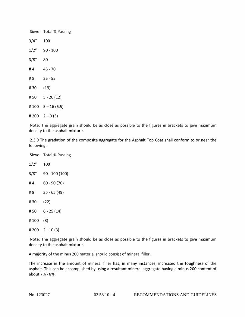
No. 123027 02 53 10 - 4 RECOMMENDATIONS AND GUIDELINES
Sieve Total % Passing
3/4” 100
1/2” 90 - 100
3/8” 80
# 4 45 - 70
# 8 25 - 55
# 30 (19)
# 50 5 - 20 (12)
# 100 5 – 16 (6.5)
# 200 2 – 9 (3)
Note: The aggregate grain should be as close as possible to the figures in brackets to give maximum density to the asphalt mixture.
2.3.9 The gradation of the composite aggregate for the Asphalt Top Coat shall conform to or near the following:
Sieve Total % Passing
1/2” 100
3/8” 90 - 100 (100)
# 4 60 - 90 (70)
# 8 35 - 65 (49)
# 30 (22)
# 50 6 - 25 (14)
# 100 (8)
# 200 2 - 10 (3)
Note: The aggregate grain should be as close as possible to the figures in brackets to give maximum density to the asphalt mixture.
A majority of the minus 200 material should consist of mineral filler.
The increase in the amount of mineral filler has, in many instances, increased the toughness of the asphalt. This can be accomplished by using a resultant mineral aggregate having a minus 200 content of about 7% - 8%.

No. 123027 02 53 10 - 5 RECOMMENDATIONS AND GUIDELINES
2.3.10 The asphalt "Binder Course" and "Top Coat" mixtures are the type IV mixes recommended by the Asphalt Institute.
Asphaltic concrete mixtures may differ from the above provided specifications, meet or exceed the present specifications. The synthetic surfacing contractor must be informed about proposed changes/deviations to the present specifications. Determination of the job mix formula shall be based on attaining a mix having a Marshall Stability (ASTM D1559, 75 blows each Side) of 750 lbs. or greater.
2.3.11 Samples of the job mix from the asphalt plant shall be laboratory tested for Marshall Stability. A compacted specimen shall be retained for density (ASTM D2726) comparison with core samples from the installed pavement.
2.4 Prime Coats and Tack Coats
2.4.1 The primer for application on crushed stone base under layers (prime coat) shall be MC-1.
2.4.2 The primer for application on asphalt surfaces (tack coat) shall be RC-1.
PART 3
EXECUTION
3.1 Sub-grade
3.1.1 The excavation levels should be determined to allow paving, pits, etc. to rest on firm, load bearing, undisturbed sub-soil, also capable of properly supporting the paving equipment and haul trucks.
3.1.2 The sub-soil shall be excavated and compacted to a surface parallel to the theoretical finished surface of the pavement and at a depth below it equal to the compacted thickness of the subsequent layers.
3.1.3 The excavation shall proceed in such a manner that disturbance of soils below the excavation level by equipment is avoided.
3.1.4 Surface shape of the sub-grade shall be such that water cannot accumulate at any point. If this is not possible, it is important to provide all necessary equipment, including automatically operated pumps and piping to run-off facilities, to maintain the excavations, pits, depressions free from accumulated water during the entire period of construction.
3.1.5 Excavation may encounter soft, non-bearing soils below the excavation level over some of the area. When the nature at the soil is such that appropriate load bearing cannot be achieved at the excavation levels originally designed, additional excavation to good bearing is necessary. The non-bearing material will be replaced with suitable ordinary fill as will permit rough grades to be as specified.
3.1.6 When encountered in the work and indicated on the drawings, all existing active sewer, water, gas, electric, steam, irrigation and other utility services and structures shall be protected at all times and, if required for the proper execution of the work, shall be relocated.
3.1.7 The sub-soil shall be rolled and compacted by a roller to a minimum density at ninety-five percent (95%) as determined by the Modified Proctor Test (AASHO T99).

No. 123027 02 53 10 - 6 RECOMMENDATIONS AND GUIDELINES
3.1.8 Should a section of the work be not acceptable on the basis of inadequate compaction, further compaction effort shall be applied until the specified standard is achieved.
3.1.9 If the moisture content varies outside the specified limits, add water or allow drying as necessary; before commencing rolling mix mechanically for a minimum depth of mm 300 to ensure uniform distribution of moisture.
3.1.10 Surface shape of the sub-grade shall comply with the tolerances itemized in the following table:
Item Characteristic Tolerance
Sub-grade Level +20mm/-20mm
Thickness
Unspecified
3.1.11 Should a section of the work be not acceptable on the basis of level, high areas shall be graded off, low areas shall be corrected by adding and compacting material similar to that already in place.
3.1.12 If the sub-grade has dried and becomes loose and dusty due to construction traffic, it should be watered, lightly bladed and rolled prior to placement of the sub-base layer.
3.1.13 The placement of the sub-base layer shall not be commenced until the sub-grade has been approved following inspection and/or testing.
3.2 Sub-base and base under layer
3.2.1 Each layer of the pavement shall be completed to a surface parallel to the theoretical finished surface of the pavement and at a depth below it equal to the compacted thickness of the subsequent layers.
3.2.2 Surface shape of each layer shall be such that water cannot accumulate at any point. If this is not possible, it is important to provide all necessary equipment, including automatically operated pumps and piping to run-off facilities, to maintain the excavations, pits, depressions free from accumulated water during the entire period of construction.
3.2.3 All fill material and crushed stone shall be spread evenly by direct tipping from suitable vehicles or by the use of a mechanical spreader above the approved sub-grade. Care should be taken to avoid segregation of granular material during tipping and spreading.
3.2.4 Layers of pavement material shall be not less than 4” (10 cm) in compacted thickness. Maximum layer thickness shall be limited to that which will allow compaction to specified densities by the equipment in use.
3.2.5 Ordinary fills material and crushed stone, when delivered, shall have a moisture content within +/- 2% of the modified optimum moisture content. During compaction moisture content shall be maintained in the correct range. If the fill material or crushed stone does not contain the proper moisture content for compaction, it shall be wetted or dried as required before rolling. Water spraying equipment used for this purpose shall be capable of uniformly distributing water in controlled quantities over uniform lane widths.

No. 123027 02 53 10 - 7 RECOMMENDATIONS AND GUIDELINES
3.2.6 Each layer of the ordinary fill material shall be disked whenever necessary to break down clods, thoroughly mix the different materials, secure a uniform moisture content and ensure uniform density and proper compaction.
3.2.7 When the moisture content and condition of each spread layer is satisfactory, the area shall be rolled by an approved type roller to a minimum density of ninety-five (95%) as determined by the Modified Proctor Test (AASHO). The final rolling shall be accomplished with a tandem steel roller. Rollers of variable mass shall receive ballast to the greatest mass that can be supported without distress to the pavement or sub-grade.
3.2.8 Surfaces of fine crushed rock shall be constructed slightly higher than the specified levels and cut to profile by power grader towards the end of the compaction process. Rolling shall then continue to specified density to produce a tight, even surface without loose stones or slurry of fines.
3.2.9 Should a section of the work be not acceptable on the basis of inadequate compaction, further compaction shall be applied until the specified standard is achieved. If the moisture content varies outside the specified limits, add water or allow drying as necessary. Before commencing rolling mix mechanically for the full depth of the layer to ensure uniform distribution of moisture.
3.2.10 Pavement base under layer courses shall comply with the tolerances itemized in the following table:
Item Characteristic Tolerance Base under layer Level +5mm / -5mm
Straightness
6mm maximum deviation from
4 meter straight-edge in all
directions
Thickness
+15mm / -15mm
Sub-base
Level
+10mm / -10mm
Thickness
+30mm / -30mm

No. 123027 02 53 10 - 8 RECOMMENDATIONS AND GUIDELINES
3.2.11 Should a section of the work be not acceptable on the basis of elevation, flatness or depth, high areas shall be graded off,
low areas shall be scarified to the full layer depth, built up as necessary and re-compacted as specified.
3.2.12 Each successive layer shall not be commenced until the underlying layer has been approved following inspection and/or testing.
3.2.13 The base under layer must be firm, non-yielding and not pumping under the travel of haul trucks and other construction equipment at the time of the laying of the hot mix asphalt. Base under layers that show movement under trucks or construction equipment will need additional compaction work or other remedial work to repair the substandard installation.
3.3 Hot Mix Asphalt Pavement.
3.3.1 Mixing of hot mix asphalt should be undertaken in a mixing plant capable of effectively drying and heating the aggregate to the specified temperature, accurately proportioning and uniformly mixing coarse and fine aggregate, filler and binder to meet the specified requirements at all times.
In general, batch-mixing plants are preferable to drum mixing plants, because of their greater capability to fine-tune the aggregate gradation.
For all types of mixing facilities:
• Cold aggregates must be handled and stored in a manner that avoids contamination and minimizes degradation and segregation.
• Filler shall be stored and handled in a separate system from that which handles aggregate
• The bitumen storage and handling shall be arranged so that contamination of the bitumen by flushing liquids or other materials cannot occur.
• The bitumen storage tanks shall be capable of holding at least sufficient bitumen for one day's production.
• Heating of bitumen shall be accomplished by steam coils, electricity or other means that will allow no direct flame to come into contact with the heating tank.
• Discharge from the plant shall be so arranged as to minimize segregation.
• Asphalt, which has been stored for more than twenty-four hours or produced at temperatures not in accordance with those specified, shall not be used.
• The mix shall leave the mixing facility at a temperature between 285°F (140°C) and 325°F (163°C).
3.3.2 The hot mix asphalt must be kept clean during hauling and covered if necessary during transit with canvas or other material that will retain the desired pavement temperatures. The mixtures must not be hauled in such a manner that segregation of the ingredients takes place or that a crust is formed on the surface, or that mixture will crumble or flatten out when dumped. Trucks that transport the mixture must have metal beds, and the beds must be clean, smooth and free of holes. Before loading, the truck

No. 123027 02 53 10 - 9 RECOMMENDATIONS AND GUIDELINES
bed is coated with a thin film of a release agent (oil or soap solution) that assists in preventing fresh hot mix asphalt from sticking to the surface of the bed. After the bed is coated, any excess release agent must be drained from the bed.
3.3.3 The hot mix asphalt shall be spread with a self-propelled machine spreader having a floating screed assembly controlling the elevation of the strike-oft. The use of road graders or towed spreaders will not be allowed. Means shall be provided to heat the screed uniformly over its full width. The screed shall be equipped with automatic screed controls to adjust automatically to place a uniform mat of desired thickness, grade and shape.
3.3.4 Typical members of the paving crew should be: paving superintendent, paver operator, dump person, two screed people, and two people to lute and take care of joints and mat repairs. Co-ordination of the entire crew with the paving superintendent and screed people is essential to achieve all the desired goals.
3.3.5 Self-propelled rollers are required as compaction equipment. Towed-type rollers should not be used.
Hand-held or vibrating plate compactors can be used in small, inaccessible areas.
Steel-wheeled non-vibrating rollers shall have a mass of 10 tons (9 metric tons).
Steel wheeled vibrating rollers shall have a mass of 5 tons (4.5 metric tons).
Pneumatic tired multi-wheeled rollers shall not be used.
3.3.6 The hot mix asphalt shall be placed with a minimum delay after delivery. On no account shall hot mix asphalt be reheated.
3.3.7 The day's work shall be organized so that each layer spread covers the full width of the pavement.
3.3.8 Hot mix asphalt shall be spread to a depth consistent with the specified compacted thickness. Each layer shall be completed to a surface parallel to the finished surface of the pavement and at a depth below it equal to the compacted thickness of the subsequent layer or layers specified.
3.3.9 Hot mix asphalt shall not be placed during rain, or when the air temperature in the shade and away from artificial heat is 40°F (5°C) or less, or while the surface is wet or when the pavement temperature does not comply with the Table below.
Pavement surface temperature in shade
Minimum Laying Temperatures
Binder Course
Minimum Laying Temperature
Top Coat
40°F - 50°F (5°C - 10°C)
302°F (150°C)

No. 123027 02 53 10 - 10 RECOMMENDATIONS AND GUIDELINES
293°F (145°C)
50°F - 60°F (10°C - 15°C)
293°F (145°C)
284°F (140°C)
60°F - 77°F (15°C - 25°C)
284°F (140°C)
275°F (135°C)
Over 77°F (Over 25°C)
275°F (135°C)
266°F (130°C)
3.3.10 Maximum laying temperature of the mixture shall be 325°F (163°C)
3.3.11 The temperature of the mix shall be measured in the truck just prior to discharging into the paver hopper. A suitable stem type thermometer shall be used. The stem shall be inserted into the mix to a depth of approximately 8" (200mm) at a location at least 12" (300mm) from the side of the truck body. An average of at least two readings shall be adopted as the temperature of the mix.
3.3.12 There are three acceptable types of sensing devices used with the automatic screed control system:
• The Wand Sensor
• The Ultra Sonic Sensor
• The Laser Sensor
3.3.13 The grade reference used with the above listed sensing devices can be either a fixed string-line tied between graded iron pins or on an existing surface, a previously placed surface, a curb line, etc.
A string-line can be erected that will include roll down factors for true grade. The roll down is estimated to be about 25% of the un-compacted mat thickness. To calculate the exact position of the string-line, a survey crew is used to determine the existing grade at approximate intervals of 9 meters (30 feet). The existing grade is subtracted from the theoretical grade for calculation of lift thickness.
A roll down factor of 25% of this thickness is added for the string-line grade. Once the string-line is erected, intermediate points of support may be placed under the string-line, especially on curves or in sudden changes of grade.
Graded iron pins and intermediate supports should be placed so that they will not interfere with the travel of the machine spreader, but close enough to each other and to the path of the machine spreader that they can hold the string in a convenient position to be reached by the electronic sensors and by a short straight edge placed on the newly laid pavement to visual check on its level.

No. 123027 02 53 10 - 11 RECOMMENDATIONS AND GUIDELINES
3.3.14 The reference system that is best for the job depends on the existing pavement surface on which the mat is to be placed.
If the surface on which the mat is to he placed has an appropriate longitudinal grade, so that the finished pavement is expected to have a constant thickness, then the surface on which the mat has to be placed, an adjoining existing surface, a previously placed surface, a curb line, etc. can be used as the reference system, since a constant roll down is expected.
If the longitudinal grade is erratic, so that the finished pavement is expected to have a variable thickness, a string-line should be used as the reference system, to take in account the variable roll down.
3.3.15 To maintain proper transverse grade, automatic screed controls use:
• A dual sensing systems on both sides of the paver, using two grade references, one on each side of the paver or
• A single sensing system on a single side of the paver, using a single grade reference on a single side of the paver, in association with an automatic slope control system: in using the transverse slope control, no specific roll down factors can be applied to grade calculations for slope transfer.
The Control System that is best for the job depends on the existing pavement surface on which the mat is to be placed.
Dual Grade Control System is preferable if the surface on which the mat has to be placed has an unsatisfactory transverse grade.
Single Grade Control System transfers the roll-down factors of the grade control side to the opposite side as equal factors, which may or may not be equal. Single Grade Control System is acceptable in situations where the surface on which the mat is to be placed has an appropriate transverse grade.
3.3.16 The area to be surfaced with hot mix asphalt shall be cleared of all foreign or loose material with power blowers, power brooms or hand brooms.
3.3.17 Crushed stone or asphalt surfaces shall be primed prior to the installation of the binder course and topcoat.
Prime crushed stone surfaces at the rate of 0.3 gallons per square yard.
Prime asphalt surfaces at the rate of 0.05 gallons per square yard.
Sprayers shall be capable of spraying the tack coat uniformly through jets in a spray bar at the desired rate of application.
Each sprayer shall be fitted with a hand lance.
Tack Coat shall be applied, not less than thirty (30) minutes nor more than two (2) hours before asphaltic concrete is placed.
When spraying the tack coat, shields shall be used and all necessary precautions taken to protect curbs, gutters, channels, adjoining structures, surfaces and grassed areas.

No. 123027 02 53 10 - 12 RECOMMENDATIONS AND GUIDELINES
Any pools of tack coat, which may form in small depressions or surface irregularities, shall be brushed out over the adjacent area with brooms or rubber squeegees before the emulsion breaks.
In dusty conditions, every precaution shall be taken to prevent freshly coated surfaces from being contaminated by dust or other foreign material.
3.3.18 Uniformity of operations is essential in hot mix asphalt paving. Uniform, continuous operation of the paver produces the highest quality pavement.
Paving too fast can result in the paver stopping frequently to wait for trucks to bring more mix. The smoothness of the pavement will suffer when the paver stops and starts up again. The paver speed should he matched to the quantity of HMA being delivered to the project to provide a uniform paver speed.
The paver must be continuously supplied with enough mix, and at the same time, trucks should not have to wait a long time to discharge their loads into the paver hopper.
3.3.19 Starting blocks equal to 1.25 times the thickness of the un-compacted mat are required to set the thickness and to null the screed. By using starting blocks the grade can be very close at the beginning of the operation.
3.3.20 Blocks equal to 25% of the un-compacted thickness are used to start from a joint. The 25% additional thickness allows for proper roll-down or compaction while maintaining proper grade.
Extended screeds will require multiple shims for each extension area.
3.3.21 The screed must be initially heated at the start of each new paving operation. If not, the mix will tear and the texture will look open and coarse, as if the mix were too cold.
3.3.22 If the mat being placed is uniform and satisfactory in texture, and the thickness is correct, no screed adjustments are required. But when adjustments are required, they should be made in small increments. Time should he allowed between the adjustments to permit the paver screed to complete reaction to the adjustments sequentially.
3.3.23 The minimum un-compacted thickness of a hot mix asphalt course is equal to 1.25 times its minimum compacted thickness, which is equal to three times the nominal maximum size aggregate. When the mat falls below this thickness, it pulls, tears, cools rapidly and generally will not be able to achieve the proper density and pavement smoothness.
3.3.24 There are places on many projects where spreading with a paver is either impractical or impossible. In these cases, hand spreading may he required. Placing and spreading by hand should be done very carefully and the material distributed uniformly so there will be no segregation of the mix. When the HMA is dumped in piles, it should be placed upon arrival on steel dump sheets outside the area in which it is to be spread and shall then be immediately laid to the required depth.
The material should be deposited from the shovels into small piles and spread with lutes. In the spreading process, all material should be thoroughly loosened and evenly distributed. Any part of the mix that has formed into lumps and does not break down easily should be discarded. After the material has been placed and before rolling starts, the surface should be checked with templates or straightedges and all irregularities corrected.

No. 123027 02 53 10 - 13 RECOMMENDATIONS AND GUIDELINES
3.3.25 Asphaltic concrete shall be spread in such a manner as to minimize the number of transverse and longitudinal joints in the pavement.
3.3.26 Transverse joints shall be constructed where the spreading operation is stopped for longer than 20 minutes. Transverse joints in adjoining spreader runs shall be offset by not less than 8 feet (2.44m). Transverse joints shall be offset from layer to layer by not less than 8 feet (2.44m). Transverse joints shall be constructed at right angles to the direction of spreading and be cut to a straight vertical face for the full depth of the layer.
3.3.27 When the construction is ready to stop for the end of the day or for a period longer than 20 minutes, the following procedure is used to form a suitable transverse joint:
1. When the paver is placing the last load, it is shifted into low gear as it approaches the location of the proposed joint.
2. As the hopper empties and the amount of material in the screed chamber decreases below normal operating level, the paver is stopped.
3. The screed is raised and the paver moved out of the way.
4. The mix is then removed from the end of the mat to form a clean, vertical edge.
5. Heavy wrapping paper is placed on the existing surface along the edge of the joint.
6. New material is finally placed on top of the paper and used to form a ramp, from the new surface to the existing surface.
3.3.28 When construction is ready to resume, the following procedure is used to form a suitable transverse joint:
1. The ramp of material is removed along with the board or paper.
2. A straightedge is used to check the longitudinal grade of the mat. Because the paver was running out of material as it laid the last few feet of mat, it is possible that those last few feet taper slightly from the specified level of the mat. If this is the case, a new transverse edge must be cut behind the point where the taper begins.
3. The vertical face of the mat is tack-coated.
4. The paver is backed up to the edge of the mat and the screed rested on the mat surface.
5. The screed is heated while it rests on the mat. This provides some heat to the material at the edge of the mat.
6. The heated screed is raised and shims as thick as the difference between the compacted and the un-compacted mat (approximately 25% of the compacted thickness) are positioned under its ends.
7. The truck with the first load of HMA is backed carefully to the hopper. During discharge of the mix from the truck bed to the paver, it is essential that the truck not bump the paver and cause it to move.
8. The paver starts forward in a low gear.

No. 123027 02 53 10 - 14 RECOMMENDATIONS AND GUIDELINES
9. Once the paver has moved away, excess asphalt is cleaned off the surface of the mat and the smoothness of the joint is checked with a straightedge.
10. If the joint is satisfactory, a 6" (150mm) width of the fresh mix is rolled transversely and the joint checked for smoothness.
If the joint is satisfactory, transverse rolling is continued in 6" to 12" (150 to 300mm.) increments until the entire width of the roller is on the new HMA. If straight edging shows an uneven joint, the surface of the new mat must he scarified while still warm and workable. Scarification is done with the fine side of the lute. Excess material can then be removed or additional material added, and the joint rolled. During rolling, timbers should he placed along the edges of the mat to prevent the roller from driving off the longitudinal edge and distorting it.
3.3.29 Longitudinal joints shall be offset from layer to layer by not less than 6" (150mm). Longitudinal joints shall be parallel to the centerline of the pavement. Alignment of the mat is dependent on the accuracy of the guideline provided for the paver operator and his alertness in following it. Attention to this detail is vital to the construction of a satisfactory longitudinal joint, since only a straight edge can be properly matched to make the joint
3.3.30 Hot joints are formed by two payers operating in echelon. The screed of the rear paver is set to match the grade or thickness of the unrolled edge of the first mat placed. The advantages of a hot joint are that the two mats are automatically matched in thickness; the density on both sides of the joint is uniform because both sides are compacted together, and the hot mats form a solid bond. The disadvantage is that traffic cannot move in one of the lanes while the other is being paved. Both lanes are blocked simultaneously.
3.3.31 In building a cold joint, one lane is placed and compacted. At a later time, after the HMA in the first lane has cooled, the companion lane is placed against it and compacted. Special precautions must be followed to ensure a joint of good quality.
3.3.32 The following procedure is used to form a suitable longitudinal joint:
1. The exposed edge of the first lane shall be formed while hot to a straight line with a dense face, which shall lie between vertical and 45° to the vertical for the full depth of the layer.
2. The unsupported longitudinal edges of spread material should be side tamped to raise the level of the asphaltic concrete slightly to secure maximum edge compaction from subsequent rolling.
3. While placing the companion lane, the paver screed should be set to overlap the first mat by 1" to 2" (25 to 50 mm).
4. The elevation of the screed above the surface of the first mat should he equal to the amount of roll-down expected during compaction of the new mat.
5. The coarse aggregate in the material overlapping the cold joint should be carefully removed and wasted. This leaves only the finer portion of the mixture to be pressed into the compacted lane at the time the joint is rolled.
3.3.33 The placing of hot mix asphalt against abutting structures such as curbs, gutter manhole or adjoining pavement shall be carried out in the same manner as for longitudinal and transverse joints.
No. 123027 02 53 10 - 15 RECOMMENDATIONS AND GUIDELINES
Any spaces left unfilled between the spreader run and abutting edges shall be filled with sufficient material to the proper height prior to compaction.
3.3.34 After the paving mixture has been property spread; it shall be thoroughly and uniformly compressed by rolling with power rollers.
3.3.35 Hot mix asphalt shall be compacted uniformly to the standard specified as soon as it will support rollers without undue displacement. All rolling shall be completed while the mix is at a temperature above 185°F (85°C)
3.3.36 The pavement shall be compacted to 97% or more of the density (ASTM F2726) obtained on a retained job mix specimen by the seventy-five blow Marshall procedure (ASTM D1559), Marshall stability (ASTM D1559) shall be 750 lbs. or greater.
3.3.37 The exact number of passes of a roller that will be required to obtain adequate density will be determined on a test strip using a nuclear density gauge to measure the density of the mat after each pass, until maximum achievable density is indicated by the test results. The rolling pattern used on the test strip should be the same that will be used on the remainder of the job. The number of rollers and/or the rate of production will be adjusted accordingly.
3.3.38 The speed of rollers at all times shall be slow enough to avoid displacement of the mix and shall not be greater than 3 mph (5 km/h).
3.3.39 Steel wheel rollers shall be operated with minimum wetting of rollers.
3.3.40 The driving roll shall be nearer the spreader.
3.3.41 Vibratory mechanisms shall be disengaged before stopping or reversing direction.
3.3.42 Rollers shall not remain stationary on asphaltic concrete while it is still warm. Roller wheels shall be kept free from any buildup.
3.3.43 The roller shall pass over the unprotected end of the freshly laid mixture only when a transverse joint has to be made.
3.3.44 Initial (breakdown) rolling shall be performed with a static steel-wheeled roller. Transverse joints shall be rolled first, then the longitudinal joint and the outside edge. Breakdown rolling shall continue longitudinally, commencing on the lower side and proceeding to the higher side of the spreader run. The roller shall overhang the unsupported edges of the run by about 4-inch (100mm). Each longitudinal pass shall overlap the previous pass by about 4-inch (100mm) and adjacent passes of the roller shall be of different lengths.
3.3.45 Secondary rolling to obtain required density before the mixture cools to 1850F (850C) shall be performed as soon as possible after initial rolling and shall be performed with a static or a vibratory steel wheeled roller. Rolling shall be carried out longitudinally commencing on the lower side and proceeding to the higher side of the spreader run. Each roller pass shall overlap the previous pass and adjacent passes shall be of different lengths.
No. 123027 02 53 10 - 16 RECOMMENDATIONS AND GUIDELINES
3.3.46 Final rolling for the improvement of the surface while the mixture is still warm enough to permit removal of any roller marks shall be performed with static steel wheeled roller.
3.3.47 When paving in echelon, the edge of the run common to adjacent spreaders shall be left unrolled for a width of 8 inch (200mm) until the longitudinal joint has been constructed. This strip shall be rolled together with the edge of the adjacent spreader run. Rolling shall commence before the temperature of the material along the edge of the first spreader run has fallen below 95 0C (203 0F)
3.4 Acceptance of paving work - remedy work.
3.4.1 Each successive layer shall not be commenced until the underlying layer has been approved following inspection and/or testing.
3.4.2 Acceptance of paving work as far as compaction and Marshall Stability specifications is concerned will be based on tests to be performed on core samples taken from each layer shortly after application. Test results shall be submitted to synthetic surfacing contractor.
3.4.3 Should a section of the work be not acceptable on the basis of inadequate compaction and/or the mixture became loose and broken, mixed with dirt or in any way defective, it shall be removed and replaced with fresh mixture which shall be immediately compacted to conform with the surrounding area.
3.4.4 Areas of one (1) square inch or more showing excess of bitumen shall be removed and replaced.
3.4.5 On completion of placement and compaction, pavement courses shall comply with the tolerances itemized in the following table.
Item
Characteristic
Tolerance
Top Coat
Level
+2mm / -2mm from design
levels
Thickness
+5mm / -0mm from design
levels
Flatness
3mm maximum departure from a

No. 123027 02 53 10 - 17 RECOMMENDATIONS AND GUIDELINES
3m straight-edge in all directions
Binder Course
Level
+4mm / -4mm from design
levels
Thickness
+5mm / -0mm from design
levels
Flatness
4mm maximum departure from a
3m straight-edge in all directions
3.4.6 Surface shape of each layer of pavement shall be such that water cannot accumulate at any point and the surface shall free drain to drainage channels.
3.4.7 The whole surface of each layer of pavement should be checked for levels by a local surveyor, and for flatness with a 10 foot straightedge in all directions; the surface shall also be flooded and inspected for ponding, "bird baths", ridges, etc. After testing, all high and low areas shall be marked on the leveling course surface.
3.4.8 Low areas shall be remedied by cutting out the course to full depth (or to a minimum depth of 3/4" – 1” (20 - 25 mm)) and replacing with the correct hot mixture. The repaired area shall be thoroughly compacted to the specified tolerance. First the area must be fully tack coated. No filling by using sand mix shall be allowed. Sand asphalt lacks sufficient internal strength. No tar emulsions such as 'jet shield" or similar products shall be applied to the surface. Nor shall any other type at asphalt or tar leveling or sealing product (hot or cold) be coated on the surface, Under specific conditions and with synthetic surfacing contractors prior approval, a polyurethane underlayment material as recommended by the manufacturer can be used for correcting small low areas. Extensive use of Polyurethane underlayment is no substitute for proper installation and leveling of the asphalt. The depth of the underlayment layer must be limited to 1/4" (6 mm) or less.
3.4.9 High areas shall be remedied by cutting out the course to full depth (or to a minimum depth of 3/4” – 1” (20 - 25 mm)) and replacing with the correct hot mixture. The repaired area shall be thoroughly compacted to the specified tolerance. In some cases it is practical to repair high areas and ridges by heating with a "hot iron" or a butane torch and scraping them off. These areas must be rolled smooth afterwards.
3.5 Curing of hot mix asphalt installations

No. 123027 02 53 10 - 18 RECOMMENDATIONS AND GUIDELINES
3.5.1 The asphalt-leveling course will have to cure a minimum of twenty eight (28) days prior to installation of the synthetic surface in order to allow the escape of surface volatiles, oils. Etc.
3.6 Disclaimer
3.6.1 The above recommendations are provided for general guidance only.
The responsibility for warranties and/or performance guarantees for the proper preparation of the asphalt and stone base rests with the responsible professional, asphalt manufacturer and/or the asphalt sub-contractor in the event of base failure and not with the synthetic surfacing contractor.
The General Contractor, Architect, and/or Asphalt Sub-Contractor will be notified by the synthetic surfacing contractor of any evident defects or installation conditions, which could result in unsatisfactory performance. The responsibility for remedying defective work rests with the General Contractor and/or the Asphalt Sub-Contractor.
The synthetic surfacing contractor must be provided with the respective tests results in advance of visiting the project site if relevant commentary is expected.
The Owner can obtain written confirmation from the synthetic surfacing contractor, based on site observations and test results supplied by the contractor, that the bituminous concrete pavement appears satisfactorily finished and adequately cured to permit the installation to begin. (Written confirmation from synthetic surfacing contractor of satisfactory completed and adequately cured asphalt pavement can be obtained by the Owner, based on synthetic surfacing contractors site observations, and test results supplied by the contractor)
The synthetic surfacing contractor will not be held responsible for any delays past expected substantial completion dates, caused by the incorrect installation of the asphalt and/or stone base. As such no liquidating damages and or penalties will be imposed on upon the synthetic surfacing contractor. Any subsequent visits to re-inspect the corrected asphalt and or stone base will be at the Sub-Contractors/General Contractors or Owners cost.

No. 123027 02 82 10 - 1 CHAIN-LINK FENCES AND GATES
SECTION 028210
CHAIN-LINK FENCES AND GATES
PART I - GENERAL
1.1 RELATED DOCUMENTS
A. Drawings and general provisions of the Contract, including General and Supplementary Conditions and Division I Specification Sections, apply to this Section.
1.2 SUMMARY
A. This Section includes the following:
1. Chain-Link Fences: Industrial.
2. Gates: swing & rolling per drawings.
B. Related Sections include the following:
1. Division 2 Section “Earthwork” for site excavation, fill, and backfill where chain-link fences and gates are located.
1.3 PERFORMANCE REQUIREMENTS
A. Structural Performance: Provide chain-link fences and gates capable of withstanding the effects of gravity loads and the following loads and stresses within limits and under conditions indicated:
1. Minimum Post Size and Maximum Spacing for Wind Velocity Pressure: Determine based on mesh size and pattern specified, and on the following minimum design wind pressures and according to CLFMI WLG 2445:
a. Wind Speed: 90 mph.
b. Fence Height: Height indicated on Drawings.
c. Line Post Group: IA, ASTM F 1043, Schedule 40 steel pipe.
d. Wind Exposure Category: C.
2. Determine minimum post size, group, and section according to ASTM F 1043 for framework up to 12 feet high, and post spacing not to exceed 10 feet.
1.4 SUBMITTALS
A. Product Data: Include construction details, material descriptions, dimensions of individual components and profiles, and finishes for chain-link fences and gates.
1. Fence and gate posts, rails, and fittings.
2. Chain-link fabric, reinforcements, and attachments.
3. Gates and hardware.
B. Shop Drawings: Show locations of fences, gates, posts, rails, tension wires, details of extended posts, extension arms, gate swing, or other operation, hardware, and accessories, Indicate materials, dimensions, sizes, weights, and finishes of components. Include plans, gate elevations, sections, details of post anchorage, attachment, bracing, and other required installation and operational clearances.
No. 123027 02 82 10 - 2 CHAIN-LINK FENCES AND GATES
1. For installed products indicated to comply with design loads, include structural analysis data signed and sealed by the qualified professional engineer responsible for their preparation.
C. Samples for Initial Selection: Manufacturer’s color charts or 6-inch lengths of actual units showing the full range of colors available for components with factory-applied color finishes.
D. Samples for Verification: For each type of chain-link fence and gate indicated.
1. Privacy slats, in 6-inch lengths in manufacturers standard colors.
1.5 QUALITY ASSURANCE
A. Installer Qualifications: An experienced installer who has completed chain-link fences and gates similar in material, design, and extent to those indicated for this Project and whose work has resulted in construction with a record of successful in-service performance.
1. Engineering Responsibility: Preparation of data for chain-link fences and gates, including Shop Drawings, based on testing and engineering analysis of manufacturer’s standard units in assemblies similar to those indicated for this Project.
B. Preinstallation Conference: Conduct conference at Project site to comply with requirements in Division I Section “Project Management and Coordination.”
1.6 PROJECT CONDITIONS
A. Field Measurements: Verify layout information for chain-link fences and gates shown on Drawings in relation to property survey and existing structures. Verify dimensions by field measurements.
B. Interruption of Existing Utility Service: Do not interrupt utility services to facilities occupied by Owner or others unless permitted under the following conditions and then only after arranging to provide temporary utility services according to requirements indicated:
1. Notify Engineer no fewer than 10 days in advance of proposed interruption of utility services.
2. Do not proceed with interruption of utility services without Engineer’s written permission.
PART 2-PRODUCTS
2.1 MANUFACTURERS
A. Manufacturers: Subject to compliance with requirements, provide products by one of the following:
1. Chain-Link Fences and Gates:
a. Allied Tube and Conduit Corp.
b. Division/Master Halco Inc.
c. Cyclone Fence/U. Diversified Group, USX Corp.
d. Merchants Metal, Inc.; Markham, IL.

No. 123027 02 82 10 - 3 CHAIN-LINK FENCES AND GATES
2.2 CHAIN-LINK FENCE FABRIC
A. General: Height indicated on Drawings. Baseball Backstops are as detailed on drawings. Provide fabric in one-piece heights measured between top and bottom of outer edge of selvage knuckle or twist. Comply with ASTM A 392, CLFMI CLF 2445, and requirements indicated below:
1. Steel Wire Fabric: Metallic-coated wire with a diameter of 0.148 inch.
a. Mesh Size: 2 inches and 1-3/4 inches at Tennis Courts.
b. Weight of Metallic (Zinc) Coating: ASTM A 392, Type II, Class 1, 1.2 oz./sq. ft. with zinc coating applied before weaving.
c. Coat selvage ends of fabric that is metallic coated before the weaving process with manufacturer’s standard clear protective coating.
2. Selvage: Knuckled at both selvages.
2.3 INDUSTRIAL FENCE FRAMING
A. Posts and Rails: Comply with ASTM F 1043 for framing, ASTM F 1083 for Group IC round pipe, and the following:
4. Line post spacing to be at 8’-O” O.C. maximum.
C. Fence Height: Height indicated on Drawings: Comply with ASTM F 1043 for framing, ASTM F 1083 for Group IC round pipe, and the following:
1. Group: IA, round steel pipe, Schedule 40
2. Strength Requirement: Light industrial according to ASTM F 1043.
3. Post Diameter and Thickness: According to ASTM F 1043 and ASTM F 1083.
a. Top Rail: 1.66 inches CD.
b. Line Post:
I. 4 feet and 5 feet high Fences: 1.875 inches OD.
II. 8 feet high Fences: 2.375 inches CD.
III. 30 feet and 15 feet high Backstop Fences: 4 inches OD.
c. End, Corner and Pull Post:
I. 4 feet and 5 feet high Fences: 2.375 inches CD.
II. 8 feet high Fences: 2.875 inches CD.
Ill. 30 feet and 15 feet high Backstop Fences: 4 inches CD.
d. Swing Gate Post: According to ASTM F 900 2.875 inches CD.
4. Line post spacing to be per manufacturers recommendations.
5. Coating for Steel Framing:
a. Metallic Coating:
b. Type B, zinc with organic overcoat, consisting of a minimum of 0.9 oz.Isq. ft. of zinc after welding, a chromate conversion coating, and a clear, verifiable polymer film.
No. 123027 02 82 10 - 4 CHAIN-LINK FENCES AND GATES
D. Post Brace Rails: Match top rail for coating and strength and stiffness requirements. Provide brace rail with truss rod assembly for each gate, end, and pull post. Provide two brace rails extending in opposing directions, each with truss rod assembly, for each corner post and for pull posts. Provide rail ends and clamps for attaching rails to posts.
E. Top Rails: Fabricate top rail from lengths 21 feet or longer, with swedged-end or fabricated for expansion-type coupling, forming a continuous rail along top of chain-link fabric.
1. Couplings to be expansion type, approximately 6-inches long, for each joint.
F. Intermediate Rails: Match top rail for coating and strength and stiffness requirements.
G. Bottom Rails: Match top rail for coating and strength and stiffness requirements.
2.4 INDUSTRIAL SWING GATES
A. General: Comply with ASTM F 900 for single and double swing gate types.
1. Metal Pipe and Tubing: Galvanized steel. Comply with ASTM F 1043 and ASTM F 1083 for materials and protective coatings.
B. Frames and Bracing: Fabricate members from round, galvanized steel tubing with outside dimension and weight according to ASTM F 900 and the following:
1. Gate Fabric Height: As indicated on Drawings.
2. Leaf Width: As indicated on Drawings.
3. Frame Members:
a. Tubular Steel: 1.90 inches round
C. Frame Corner Construction:
1. Welded or assembled with corner fittings.
D. Hardware: Latches permitting operation from both sides of gate, hinges, center gate stops and keepers for each gate leaf more than 5 feet wide. Fabricate latches with integral eye openings for padlocking; padlock accessible from both sides of gate.
1. Hinges: Non-lift-off type, offset to permit 180 degree gate opening. Provide 1 ½” pair of hinges foe each leaf over 6’0” nominal height.
2. Latch: Forked type or plunger-bar type to permit operation from either side of gate, with padlock eye as integral part of latch.
3. Padlocks by Owner.
2.5 CHAIN LINK INTERNAL TRACK ALUMINUM CANTILEVER SLIDE GATE
A. Aluminum cantilever slide gate single leaf 23'-0" opening by 42" high shall be of the internal roller design per ASTM F1184 Type II Class 2. Cantilever slide gate to be constructed of ASTM B221 aluminum members welded and designed for maximum structural integrity. Vertical external and internal members minimum 2” (50 mm) square, spaced maximum 8’ 0” (2.44 m) on center. Gates having fabric greater than 8’ 0” (2.44 m) in height require a horizontal member. The top horizontal member shall be a one-piece precision extruded structural framing member having an integral enclosed track. Bottom horizontal member to be minimum 2” x 4” (50 x 100

No. 123027 02 82 10 - 5 CHAIN-LINK FENCES AND GATES
mm). Adjustable diagonal X trusses shall be installed in each gate panel to transfer the alternating forces as the gate slides. The gate opening portion shall be filled with chain link fabric stretched taut and secured to the frame members. Chain link fabric shall match the fence system specification. The overall gate structure shall be a minimum of 40% larger than the gate opening to support the cantilevered portion of the gate in the closed position with minimum deflection per ASTM F1184. The minimum 40% back frame does not require the installation of chain link fabric for those gates not to be electrically operated. Single leaf cantilever design for openings larger than 30’ 0” (9.15 m) up to 40’ 0” (12.2 m) shall be fabricated by welding together two horizontal top structural/track members creating a dual track system. Single track gates up to 30’ 0” (9.15 m) opening require two support posts and two internal truck assemblies. Dual track gates over 30’ 0” (9.15 m) up to 40’ 0” (12.2 m) require two sets of dual posts and four internal truck assemblies.
B. Internal truck assemblies shall be capable of swiveling to accommodate gate movement and
ensure full contact of the four support wheels and two guide wheels to the internal track surface. The galvanized steel truck assembly post bracket, truck assembly vertical support axle as well as the support wheels shall be designed to handle static and dynamic forces required to support and operate the gate. The truck assembly, support axle and internal wheels shall be comprised of stainless steel or galvanized steel components.
C. Galvanized steel bottom guide roller brackets containing two 3” (75 mm) rubber wheels shall be supplied to keep the bottom of the gate plumb and in proper alignment.
D. Single gates shall be supplied with a galvanized steel latch mechanism capable of securing the gate with a padlock accessible from either side. Double gates to have galvanized drop rod to hold inactive leaf and a latch mechanism capable of securing the gate with a padlock accessible from either side. Provide drop rod receiver to engage center drop rod.
E. Cantilever gate posts shall be 4.00” (101.6 mm) OD Grade 2 pipe ASTM F1043 Group IC per section 2.3. Single leaf cantilevers up to 30’ 0” (9.15 m) require three 4” (101.6 mm) OD posts, dual track single leaf cantilevers over 30’ 0” (9.15 m) up to 40’ 0” (12.2 m) require two sets of pre fabricated dual 4.00” (101.6 mm) OD support posts and one 4” (101.6 mm) latch post. (Gate is supported in the center of the dual posts.
2.6 FITTINGS
A. General: Comply with ASTM F 626.
B. Rail Fittings: Provide the following:
1. Top Rail Sleeves: Pressed-steel or round-steel tubing not less than 6 inches long.
C. Tie Wires, Clips, and Fasteners: According to ASTM F 626.
1. Standard Round Wire Ties: For attaching chain-link fabric to posts, rails, and frames, complying with the following:
a. Hot-Dip Galvanized Steel: 0.148-inch diameter wire galvanized coating thickness matching coating thickness of chain-link fence fabric.
D. Finish:
No. 123027 02 82 10 - 6 CHAIN-LINK FENCES AND GATES
1. Metallic Coating for Pressed Steel or Cast Iron: Not less than 1.2 oz. /sq. ft. zinc.
2.6 CAST-IN-PLACE CONCRETE
A. Materials: Portland cement complying with ASTM C 150, Type I aggregates complying with ASTM C 33, and potable water for ready-mixed concrete complying with ASTM C 94/C 94M.
1. Concrete Mixes: Normal-weight concrete air entrained with not less than 3000-psi compressive strength (28 days), 3-inch slump, and 1-inch maximum size aggregate.
PART 3 - EXECUTION
3.1 EXAMINATION
A. Examine areas and conditions, with Installer present, for compliance with requirements for site clearing, earthwork, pavement work, and other conditions affecting performance.
1. Do not begin installation before final grading is completed, unless otherwise permitted by Engineer.
2. Proceed with installation only after unsatisfactory conditions have been corrected.
3.2 PREPARATION
A. Stake locations of fence lines, gates, and terminal posts. Do not exceed intervals of 500 feet or line of sight between stakes. Indicate locations of utilities, lawn sprinkler system, underground structures, benchmarks, and property monuments.
3.3 INSTALLATION, GENERAL
A. Install chain-link fencing to comply with ASTM F 567 and more stringent requirements specified.
1. Install fencing on established boundary lines inside property line.
3.4 CHAIN-LINK FENCE INSTALLATION
A. Post Excavation: Drill or hand-excavate holes for posts to diameters and spacings indicated, in firm, undisturbed soil.
B. Post Setting: Set posts in concrete at indicated spacing into firm, undisturbed soil.
1. Verify that posts are set plumb, aligned, and at correct height and spacing, and hold in position during setting with concrete or mechanical devices.
2. Concrete Fill: Place concrete around posts to dimensions indicated and vibrate or tamp for consolidation. Protect aboveground portion of posts from concrete splatter.
a. Concealed Concrete: Top 2 inches below grade to allow covering with surface material.
C. Terminal Posts: Locate terminal end, corner, and gate posts per ASTM F 567 and terminal pull posts at changes in horizontal or vertical alignment of 30 degrees or more.
D. Line Posts: Space line posts uniformly at 8 feet to 10 feet as shown on drawings. Install per manufacturer recommendations.
E. Post Bracing and Intermediate Rails: Install according to ASTM F 567, maintaining plumb position and alignment of fencing. Install braces at end and gate posts and at both sides of corner and pull posts.

No. 123027 02 82 10 - 7 CHAIN-LINK FENCES AND GATES
1. Locate horizontal braces at midheight of fabric 6 feet or higher, on fences with top rail and at 2/3 fabric height on fences without top rail. Install so posts are plumb when diagonal rod is under proper tension.
F. Tension Wire: Install according to ASTM F 567, maintaining plumb position and alignment of fencing. Pull wire taut, without sags. Fasten fabric to tension wire with 0.120-inch diameter hog rings of same material and finish as fabric wire, spaced a maximum of 24 inches o.c. Install tension wire in locations indicated before stretching fabric.
G. Top Rail: Install according to ASTM F 567, maintaining plumb position and alignment of fencing. Run rail continuously through line post caps, bending to radius for curved runs and terminating into rail end attached to posts or post caps fabricated to receive rail at terminal posts. Provide expansion couplings as recommended in writing by fencing manufacturer.
H. Bottom Rails: Install, spanning between posts.
I. Chain-Link Fabric: Apply fabric to outside of enclosing framework. Leave I inch between finish grade or surface and bottom selvage, unless otherwise indicated. Pull fabric taut and tie to posts, rails, and tension wires. Anchor to framework so fabric remains under tension after pulling force is released.
J. Tension or Stretcher Bars: Thread through fabric and secure to end, corner, pull, and gate posts with tension bands spaced not more than 15 inches o.c.
K. Tie Wires: Use wire of proper length to firmly secure fabric to line posts and rails. Attach wire at I end to chain-link fabric, wrap wire around post a minimum of 180 degrees, and attach other end to chain-link fabric per ASTM F 626. Bend ends of wire to minimize hazard to individuals and clothing.
1. Maximum Spacing: Tie fabric to line posts at 12 inches o.c. and to braces at 24 inches o.c.
L. Fasteners: Install nuts for tension bands and carriage bolts on the side of the fence opposite the fabric side. Delete first paragraph and subparagraphs below if not applicable.
M. Privacy Slats: Install slats in direction indicated, securely locked in place.
1. Diagonally, for privacy factor of 80 to 85.
3.5 GATE INSTALLATION
A. Install gates according to manufacturer’s written instructions, level, plumb, and secure for full opening without interference. Attach fabric as for fencing. Attach hardware using tamper-resistant or concealed means. Install ground-set items in concrete for anchorage. Adjust hardware for smooth operation and lubricate where necessary.
3.6 ADJUSTING
A. Gate: Adjust gate to operate smoothly, easily, and quietly, free of binding, warp, excessive deflection, distortion, nonalignment, misplacement, disruption, or malfunction, throughout entire operational range. Confirm that latches and locks engage accurately and securely without forcing or binding.
B. Lubricate hardware and other moving parts.
END OF SECTION 02821

No. 123027 03 10 00 - 1 CONCRETE FORMING AND ACCESSORIES
SECTION 03 10 00
CONCRETE FORMING AND ACCESSORIES
PART 1 GENERAL
1.01 RELATED DOCUMENTS
A. Drawings, Details of Construction, and General Provisions of the Contract, including General and Supplementary
Conditions and Division - 1 Specification Sections, apply to this Section.
1.02 SECTION INCLUDES
A. Formwork for cast-in place concrete, with shoring, bracing and anchorage.
B. Form accessories.
C. Form stripping.
1.03 PRODUCTS INSTALLED BUT NOT FURNISHED UNDER THIS SECTION:
A. Embedded steel and miscellaneous items.
1.04 RELATED REQUIREMENTS
A. Section 01 45 33 - Structural Testing and Special Inspection
B. Section 03 20 00 - Concrete Reinforcing.
C. Section 03 30 00 - Cast-in-Place Concrete.
1.05 REFERENCE STANDARDS
A. ACI 117 - Standard Specifications for Tolerances for Concrete Construction and Materials; 2006.
B. ACI 301 - Specifications for Structural Concrete for Buildings; American Concrete Institute; 2005.
C. ACI 318 - Building Code Requirements for Structural Concrete and Commentary; American Concrete Institute
International; 2005.
D. ACI 347 - Guide to Formwork for Concrete; American Concrete Institute; 2004.
1.06 DESIGN REQUIREMENTS
A. Design, engineer and construct formwork, shoring and bracing to conform to design and code requirements;
resultant concrete to conform to required shape, line and dimension.
1.07 SUBMITTALS
A. See Section 01 30 00 - Administrative Requirements, for submittal procedures.
B. Product Data: Provide data on void form materials and installation requirements.
C. Submit product data for form release agents, form materials, form ties, shelf angle inserts, dovetail anchor slots,
flashing reglets, and waterstops.
1.08 QUALITY ASSURANCE
A. Perform work of this section in accordance with ACI 347, ACI 301, and ACI 318.
1.09 DELIVERY, STORAGE, AND HANDLING
A. Deliver void forms and installation instructions in manufacturer's packaging.
B. Store void forms off ground in ventilated and protected manner to prevent deterioration from moisture.

No. 123027 03 10 00 - 2 CONCRETE FORMING AND ACCESSORIES
PART 2 PRODUCTS
2.01 FORMWORK - GENERAL
A. Provide concrete forms, accessories, shoring, and bracing as required to accomplish cast-in-place concrete work.
B. Design and construct to provide resultant concrete that conforms to design with respect to shape, lines, and
dimensions.
C. Comply with applicable State and local codes with respect to design, fabrication, erection, and removal of
formwork.
D. Comply with relevant portions of ACI 347, ACI 301, and ACI 318.
2.02 WOOD FORM MATERIALS
A. Form Materials: At the discretion of the Contractor.
2.03 FORMWORK ACCESSORIES
A. Form Ties: Removable type, galvanized metal, adjustable length, free of defects that could leave holes larger than
1 inch in concrete surface.
B. Form Release Agent: Colorless mineral oil that will not stain concrete, absorb moisture, impair natural bonding
of concrete finish coatings, or affect color characteristics of concrete finish coatings.
C. Corners: Chamfered, wood strip type; 3/4x3/4 inch size; maximum possible lengths.
D. Dovetail Anchor Slot: Galvanized steel, 22 gage thick, foam filled, release tape sealed slots, anchors for securing
to concrete formwork. Match to tie manufacturer.
E. Flashing Reglets: Galvanized steel, 22 gage thick, longest possible lengths, with alignment splines for joints, foam
filled, release tape sealed slots, anchors for securing to concrete formwork.
F. Waterstops: Preformed mineral colloid strips, 3/8 inch thick, moisture expanding. Provide Waterstop-RX
manufactured by Colloid Environmental Technologies, Hydrotite manufactured by Greenstreak, or approved
equal.
G. Shelf Angle Inserts: Wedge type for 5/8" diameter askew bolts. Include horseshoe shims. Minimum capacity
2,100 pounds. Hohmann and Barnard, Heckmann Building Products, Richmond Screw Anchor Company, or
approved equal.
H. PVC Weeps: 3" diameter PVC pipe.
PART 3 EXECUTION
3.01 EXAMINATION
A. Establish a bench mark in an accessible location and use as a reference point for various construction levels.
Maintain in an undisturbed condition until final completion.
B. Verify lines, levels and centers before proceeding with formwork. Ensure that dimensions agree with drawings.
3.02 EARTH FORMS
A. Earth forms are not permitted.
3.03 ERECTION - FORMWORK
A. Erect formwork, shoring and bracing to achieve design requirements, in accordance with requirements of ACI 301.
B. Provide bracing to ensure stability of formwork. Shore or strengthen formwork subject to overstressing by
construction loads.
C. Hold inner and outer forms for vertical concrete together with combination steel ties and spreaders accepted by the
Architect.
D. Lay out all work and check general building lines and levels established. Coordinate layout and measurements
No. 123027 03 10 00 - 3 CONCRETE FORMING AND ACCESSORIES
and if discrepancies arise, report them to the Architect.
E. Keep wood forms wet as necessary to prevent shrinkage.
F. Arrange and assemble formwork to permit dismantling and stripping. Do not damage concrete during stripping.
Permit removal of remaining principal shores.
G. Align joints and make watertight. Keep form joints to a minimum.
H. Obtain approval before framing openings in structural members that are not indicated on drawings.
I. Provide chamfer strips on exposed external corners of columns and walls.
J. Coordinate this section with other sections of work that require attachment of components to formwork.
K. If formwork is placed after reinforcement, resulting in insufficient concrete cover over reinforcement, request
instructions from Architect before proceeding.
L. Protect work at all times against the elements and other hazards. Cover and secure work.
3.04 APPLICATION - FORM RELEASE AGENT
A. Apply form release agent on formwork in accordance with manufacturer's recommendations.
B. Apply prior to placement of reinforcing steel, anchoring devices, and embedded items.
C. Do not apply form release agent where concrete surfaces will receive special finishes or applied coverings that are
affected by agent. Soak inside surfaces of untreated forms with clean water. Keep surfaces coated prior to
placement of concrete.
3.05 INSERTS, EMBEDDED PARTS, AND OPENINGS
A. Provide formed openings where required for items to be embedded in passing through concrete work.
B. Locate and set in place items that will be cast directly into concrete.
C. Coordinate with work of other sections in forming and placing openings, slots, reglets, recesses, sleeves, bolts,
anchors, other inserts, and components of other work.
D. Build in recessed anchor slots for masonry veneer into concrete walls, columns, piers, beams, and spandrels deeper
than 14 inches and wider than 16 inches. Position recessed anchor slots vertically, spaced at 16" on center.
E. Install accessories in accordance with manufacturer's instructions, so they are straight, level, and plumb. Ensure
items are not disturbed during concrete placement.
3.06 FORM CLEANING
A. Clean forms as erection proceeds, to remove foreign matter within forms.
B. Clean formed cavities of debris prior to placing concrete.
1. Flush with water or use compressed air to remove remaining foreign matter. Ensure that water and debris
drain to exterior through clean-out ports.
2. During cold weather, remove ice and snow from within forms. Do not use de-icing salts. Do not use water
to clean out forms, unless formwork and concrete construction proceed within heated enclosure. Use
compressed air or other means to remove foreign matter.
3.07 FORMWORK TOLERANCES
A. Construct formwork to maintain tolerances required by ACI 117.
1. Provide Class B surface for exposed concrete.
2. Provide Class C surface for concealed concrete.
3. Provide Class C or Class D surface for concealed pan and joist forms.
B. Tolerances given in ACI 117 are not cumulative. Maximum tolerance for any formed surface, except footings,

No. 123027 03 10 00 - 4 CONCRETE FORMING AND ACCESSORIES
shall be one inch.
3.08 FIELD QUALITY CONTROL
A. Structural Special Inspection
1. Structural Special Inspection shall be performed by qualified parties as specified herein, and in accordance
with the provision of Section 01 4533.
2. Formwork for slabs on grade, strip footings without transverse reinforcement, and topping slabs does not
require inspection. Additional exceptions may be noted on the structural drawings.
3. Personnel Qualifications: Special Inspector – Structural I: ICBO certified concrete inspector or a graduate
civil/structural engineer, or other personnel acceptable to the Structural Engineer of Record (SER), with the
experience in the design of structural systems of this type. Inspections shall be performed under the direct
supervision of a licensed structural engineer, as defined in Section 01 4533. The licensed engineer shall
review and approve all inspection reports.
4. The Owner will provide the following inspections:
a. Verify formwork for all concrete, except as noted above, will result in member size, location, and
configuration as described on the contract documents, only as it affects the structural integrity of the
concrete elements to be placed. Verify removal of shoring conforms to this section. Qualifications:
Structural I.
3.09 FORM REMOVAL
A. Do not remove forms or bracing until concrete has gained sufficient strength to carry its own weight and imposed
loads.
B. Forms for sides of beams, columns, and footings shall remain in place for a minimum of 24 hours.
C. Form Removal for Horizontal Members (Non-Post-Tensioned):
1. Do not remove horizontal member soffit forms until one of the following has been met:
a. At least one third of cylinders field cured according to ASTM C31 reach 100% of the specified 28-day
strength.
1) Prepare at least six cylinders from the final 100 cubic yards, or portions thereof, plus at least three
cylinders for each 2 hours of placing time or each additional 100 cubic yards of concrete placed,
whichever provides the greater number of cylinders.
2) Coordinate number of cylinders, testing dates, and all associated costs with the Owner's testing
laboratory
2. Provide reshores if members must support any superimposed loads. Place reshores the same day forms are
removed. Do not remove reshores until concrete has reached its specified strength.
a. Apply no construction loads to members being reshored during reshoring operations.
D. Loosen forms carefully. Do not wedge pry bars, hammers, or tools against finish concrete surfaces scheduled for
exposure to view.
E. Store removed forms to prevent damage to form materials or to fresh concrete. Discard damaged forms.
END OF SECTION

No. 123027 03 15 10 - 1 POST-INSTALLED ANCHORS
SECTION 03 15 10
POST-INSTALLED ANCHORS
PART 1 GENERAL
1.01 CONTRACT CONDITIONS
A. Drawings, Details of Construction, and General Provisions of the Contract, including General and Supplementary
Conditions and Division - 1 Specification Sections, apply to this Section.
1.02 SECTION INCLUDES
A. Requirements pertaining to post-installed anchors for materials and equipment. This section pertains to Divisions
3, 4, 5, and 6 of these specifications that require post-installed anchors, unless specified otherwise.
1.03 RELATED REQUIREMENTS
A. Division 1 – General Requirements
B. Division 3 – Concrete
1.04 REFERENCES
A. ACI 355.2 – Standard for Evaluating the Performance of Post-Installed Mechanical Anchors in Concrete; 2005
B. ASTM A 36 – Standard Specification for Carbon Structural Steel; 2005
C. ASTM A 193 – Standard Specification for Alloy-Steel and Stainless Steel Bolting Materials for High-Temperature
Service
D. ASTM A 307 – Standard Specification for Carbon Steel Bolts and Studs, 60,000 psi Tensile Strength; 2007b
E. ASTM A 510 - Standard Specification for General Requirements for Wire Rods and Coarse Round Wire, Carbon
Steel; 2007
F. ASTM A 615 – Standard Specification for Deformed and Plain Billet-Steel Bars for Concrete Reinforcement;
2007
G. ASTM A 706/A 706M - Standard Specification for Low-Alloy Steel Deformed and Plain Bars for Concrete
Reinforcement; 2006a.
H. ASTM B 633 – Standard Specification for Electrodeposited Coatings of Zinc on Iron and Steel; 2007
I. ASTM B 695 – Standard Specification for Coatings of Zinc Mechanically Deposited on Iron and Steel; 2004
J. ASTM C 881– Standard Specification Epoxy-Resin-Based Bonding Systems for Concrete; 2002
K. ASTM F 593 – Standard Specification for Stainless Steel Bolts, Hex Cap Screws, and Studs; 2002
L. ASTM F 1554 - Standard Specification for Anchor Bolts, Steel, 36, 55, and 105-ksi Yield Strength; 2007a.
M. Federal Specifications A-A-1922A, A-A01923A and A-A-55614 for Expansion and Shield-Type Anchors
N. ICC-ES AC01 – Acceptance Criteria for Expansion Anchors in Masonry Elements; 2006
O. ICC-ES AC58 – Acceptance Criteria for Adhesive Anchors in Masonry Elements; 2006
P. ICC-ES AC70 – Acceptance Criteria for Fasteners Power-Driven into Concrete, Steel and Masonry Elements;
2006
Q. ICC-ES AC106 – Acceptance Criteria for Predrilled Fasteners (Screw Anchors) in Concrete or Masonry Elements;
2006
R. ICC-ES AC193 – Acceptance Criteria for Mechanical Anchors in Concrete Elements; 2008
S. ICC-ES AC308 – Acceptance Criteria for Post-Installed Adhesive Anchors in Concrete Elements; 2008

No. 123027 03 15 10 - 2 POST-INSTALLED ANCHORS
1.05 QUALITY ASSURANCE
A. Post-Installed anchors and related materials shall be listed by one or more of the following agencies, as applicable:
1. ICC Evaluation Service
2. Underwriters Laboratories (UL) and/or Factory Mutual (FM)
1.06 SUBMITTALS
A. Product Data: Submit data for proprietary materials, manufacturer’s specifications (including finishes and/or
materials), Material Safety Data Sheets (MSDS) and installation procedures.
B. Test Reports: ICC-ES listings.
1.07 SUBSTITUTIONS
A. Only manufacturers with an ICC-ES listing will be considered for substitution requests.
B. The contractor shall submit for Engineer-of-Record’s review, calculations that are prepared & sealed by a
registered Professional Engineer demonstrating that the substituted product is capable of achieving the pertinent
equivalent performance values of the specified product using the appropriate design procedure and/or standard(s)
as required by the Building Code. In addition, the calculations shall specify the diameter and embedment depth of
the substituted product.
C. Any increase in material costs for such submittal shall be the responsibility of the contractor.
1.08 DELIVERY, STORAGE, AND HANDLING
A. Deliver products to job site in manufacturer’s or distributor’s packaging undamaged, complete with installation
instructions.
B. Protect and handle materials in accordance with manufacturer’s recommendations to prevent damage or
deterioration.
PART 2 PRODUCTS
2.01 MATERIALS
A. Expansion Anchors
1. Concrete Wedge Anchors (expansion bolt):
a. Carbon steel, ASTM B 633, Class SC1, Type I or III.
b. Stainless steel anchors (where noted): ASTM F 593, Type 303, 304 or 316.
c. Evaluation report issued by ICC-ES required.
d. Tested and qualified for performance in cracked and uncracked concrete in accordance with ACI 355.2
and ICC-ES AC193 for all mandatory tests.
e. Acceptable products include:
1) Simpson Strong-Tie: Strong-Bolt (ICC-ES ESR-1771).
2) Hilti: Kwik Bolt TZ (ICC-ES ESR-1917).
3) Powers Fasteners: Power-Stud+SD2 (ICC-ES ESR-2502).
4) ITW Red Head: Trubolt+ (ICC-ES ESR-2427)
2. Masonry Wedge Anchors (expansion bolt): Federal Specification A-A-1923A, Type 4.
a. Carbon steel, electroplated zinc finish unless otherwise noted.
b. Mechanically galvanized (where noted): ASTM B 695, Class 55, Type 1.
c. Stainless steel anchors (where noted): ASTM F 593, Type 303, 304 or 316.
d. Evaluation report issued by ICC-ES required.
e. Tested in accordance with ICC-ES AC01 for all mandatory tests:

No. 123027 03 15 10 - 3 POST-INSTALLED ANCHORS
f. Acceptable Products Include:
1) Simpson Strong-Tie: Wedge-All (ICC-ES ESR-1396).
2) Hilti: Kwik Bolt 3 (ICC-ES ESR-1385).
B. Adhesive Anchors
1. Adhesive anchors consist of an insert and an adhesive.
2. Inserts
a. Threaded Rod Inserts: Provide preparation or configuration as recommended by manufacturer.
1) Interior Exposure: ASTM A 307, ASTM A 36, ASTM A 193 Grade B7, or ASTM F 1554.
b. Reinforcing Bar Inserts: ASTM A 615 or ASTM A 706. Provide preparation or configuration as
recommended by manufacturer.
3. Adhesives for Concrete:
a. Evaluation report issued by ICC-ES required.
b. Tested and qualified for use in cracked and uncracked concrete in accordance with ICC-ES AC308 for
all mandatory and optional seismic tests including creep tests.
c. Epoxy: ASTM C 881 Type IV, Grade 3, Class B and C.
1) Acceptable products include:
(a) Simpson Strong-Tie: SET XP (ICC-ES ESR-2508).
(b) Hilti: RE-500-SD (ICC-ES ESR-2322).
(c) Powers Fasteners: PE1000+ (ICC-ES ESR-2583).
4. Adhesives for Solid Concrete Masonry:
a. Evaluation report issued by ICC-ES required.
b. Tested in accordance with ICC-ES AC58 for all mandatory tests and the following optional tests:
1) Seismic tests
2) Creep tests
3) Dampness tests
4) Freeze-thaw tests
c. Epoxy: ASTM C 881 Type IV, Grade 3, Class B and C.
1) Acceptable products include:
(a) Simpson Strong-Tie: SET Epoxy-Tie High-Strength Adhesive (ICC-ES ESR-1772).
(b) Powers Fasteners: Power-Fast+ Epoxy Adhesive, Standard Set Formulation (ICC-ES
ESR-1531).
5. Adhesives for Hollow Concrete Masonry:
a. Evaluation report issued by ICC-ES required.
b. Tested in accordance with ICC-ES AC58 for all mandatory tests and the following optional tests:.
1) Seismic tests
2) Creep tests
3) Dampness tests
4) Freeze-thaw tests
c. Epoxy: ASTM C881 Type IV, Grade 3, Class B and C.
1) Acceptable products include:
(a) Simpson Strong-Tie: SET Epoxy-Tie High-Strength Adhesive (ICC-ES ESR-1772).
(b) Hilti: RE 500.
(c) Powers Fasteners: Power-Fast+ Epoxy Adhesive, Standard Set Formulation (ICC-ES
ESR-1531).

No. 123027 03 15 10 - 4 POST-INSTALLED ANCHORS
C. Concrete and Masonry Screw Anchors
1. Concrete Screw Anchors:
a. Carbon steel heat-treated or hardened.
b. Zinc-plated in accordance with ASTM B 633, Class SC1, Type I or equivalent coating.
c. Evaluation report issued by ICC-ES required.
d. Tested per ICC-ES AC193 for all mandatory tests.
e. Acceptable products include:
1) Simpson Strong-Tie: Titen HD (ICC-ES ESR-2713).
2) Powers Fasteners: Wedge-Bolt+ (ICC-ES ESR-2526).
2. Masonry Screw Anchors: (Grouted Masonry Only)
a. Carbon steel heat-treated or hardened.
b. Zinc-plated per ASTM B 633, Class SC1, Type I, mechanically galvanized per ASTM B 695, or
equivalent coating.
c. Evaluation report issued by ICC-ES required.
d. Tested per ICC-ES AC106 for all mandatory tests (and seismic tests):
e. Acceptable products include:
1) Simpson Strong-Tie: Titen HD (ICC-ES ESR-1056).
2) Hilti: HUS-H (ICC-ES ESR-2369).
3) Powers Fasteners: Wedge-Bolt+ (ICC-ES ESR-1678).
D. Power Driven Fasteners
1. Drive pin and threaded stud types, as applicable for each condition.
2. Manufactured from ASTM A 510, Grade 1060 to1070 or AISI 1060 to 1070 steel
3. Rockwell “C” Hardness of 49-56.
4. Mechanically galvanized or zinc-plated finish.
5. Minimum diameter 0.145"
6. Smooth shank for concrete and masonry, knurled shank for steel.
7. Evaluation report issued by ICC-ES required.
8. Tested in accordance with ICC-ES AC70.
9. Acceptable products include:
a. Simpson Strong-Tie: Power Driven Fasteners (ICC-ES ESR-2138).
b. Hilti: Low Velocity Power-Driven Fasteners (ICC-ES ESR-1663).
c. ITW Ramset: Ramset Power-Driven Fasteners (ICC-ES ESR-1799).
PART 3 EXECUTION
3.01 INSTALLATION
A. Install anchors in strict accordance with manufacturer's printed instructions and, where required, requirements of
ICC-ES evaluation reports.
B. Conform to manufacturer's requirements for, but not limited to, hole drilling methods, hole size, hole cleaning,
substrate and adhesive temperatures, moisture presence in holes, and required edge distance and spacing.
C. Use special tools when recommended by manufacturer for installation of anchors unless otherwise permitted
No. 123027 03 15 10 - 5 POST-INSTALLED ANCHORS
specifically by the Engineer or Architect of Record.
D. Drill holes in concrete, in accordance with the manufacturer’s recommendations.
3.02 FIELD QUALITY CONTROL
A. Manufacturer shall, on request, provide the services of a field representative to demonstrate to and train installers
in proper installation techniques.
B. Structural Testing and Special Inspection
1. Structural Special Inspection shall be performed by qualified parties as specified herein, and in accordance
with the provision of Section 01 4533.
2. Special Inspection, periodic or continuous, of post-installed anchors shall be provided as specified herein, but
not less than as required by ICC-ES evaluation reports.
3. Definitions: ASNT - American Society for Non-Destructive Testing
4. Personnel Qualifications
a. Special Inspector Technical I: ASNT Level I, employed by a testing agency and supervised by an
ASNT Level III with a minimum of 10 years experience.
b. Special Inspector Technical II: ASNT Level II, employed by a testing agency and supervised by an
ASNT Level III with a minimum of 10 years experience.
c. Special Inspector – Structural I: Graduate civil/structural engineer, or other personnel acceptable to the
SER, with experience in design of structural systems of the project type. Inspections shall be
performed under the direct supervision of a licensed structural engineer, as defined in Section 01 4533.
The licensed engineer shall review and approve all inspection reports.
5. The Owner will provide the following tests and inspections:
a. Continuous special inspection during installation to verify materials delivered to site comply with
contract documents, bolt type and dimensions, concrete type and compressive strength, pre-drilled hole
dimensions and cleaning, embedment, spacing, edge distances, slab thickness, tightening torque, and
any other items requiring inspection by product's ICC approval report. Qualifications: Technical II or
Structural I.
C. Provide pullout and shear tests, in addition to Special Inspection, to determine the adequacy of anchors.
Independent test laboratory and/or Engineer of Record to establish the test program. Perform in accordance with
appropriate ASTM test standards. Field tests shall be non-destructive whenever possible.
END OF SECTION
No. 123027 03 20 00 - 1 CONCRETE REINFORCING
SECTION 03 20 00
CONCRETE REINFORCING
PART 1 GENERAL
1.01 RELATED DOCUMENTS
A. Drawings, Details of Construction, and General Provisions of the Contract, including General and Supplementary
Conditions and Division - 1 Specification Sections, apply to this Section.
1.02 SECTION INCLUDES
A. Reinforcing steel for cast-in-place concrete.
B. Supports and accessories for steel reinforcement.
1.03 RELATED REQUIREMENTS
A. Section 01 4533 - Structural Testing and Special Inspection
B. Section 03 1000 - Concrete Forming and Accessories.
C. Section 03 1510 - Post-Installed Anchors.
D. Section 03 3000 - Cast-in-Place Concrete.
1.04 REFERENCE STANDARDS
A. ACI 117 - Standard Specification for Tolerances for Concrete Construction and Materials; 2007
B. ACI 301 - Specifications for Structural Concrete for Buildings; American Concrete Institute International; 2005.
C. ACI 315 - Details and Detailing of Concrete Reinforcement; 1999
D. ACI 318 - Building Code Requirements for Structural Concrete and Commentary; American Concrete Institute
International; 2005.
E. ASTM A 82/A 82M - Standard Specification for Steel Wire, Plain, for Concrete Reinforcement; 2007.
F. ASTM A 185/A 185M - Standard Specification for Steel Welded Wire Reinforcement, Plain, for Concrete; 2007.
G. ASTM A 615/A 615M - Standard Specification for Deformed and Plain Billet-Steel Bars for Concrete
Reinforcement; 2007.
H. ASTM A 775/A 775M - Standard Specification for Epoxy-Coated Steel Reinforcing Bars; 2007b.
I. ASTM C881 - Standard Specification for Epoxy-Resin-Base Bonding Systems for Concrete; 2002
J. ASTM D 3963/D 3963M - Standard Specification for Fabrication and Jobsite Handling of Epoxy Coated
Reinforcing Steel Bars; 2001 (Reapproved 2007).
K. CRSI (DA4) - Manual of Standard Practice; Concrete Reinforcing Steel Institute; 2001.
L. CRSI (P1) - Placing Reinforcing Bars; Concrete Reinforcing Steel Institute; Eighth Edition.
1.05 SUBMITTALS
A. See Section 01 3000 - Administrative Requirements, for submittal procedures.
B. Shop Drawings: Follow recommended practices of ACI 315. Include size, length, bar schedules, shapes of bent
bars, spacing of bars, methods of supporting reinforcing, and location and length of splices. Provide details as
necessary to show final position of reinforcement in elements.
1. Include shop drawings for masonry reinforcing
C. Product Data: Submit mechanical splices, adhesive for rebar anchorage, and epoxy coating repair material.

No. 123027 03 20 00 - 2 CONCRETE REINFORCING
1.06 QUALITY ASSURANCE
A. Perform work of this section in accordance with ACI 301 and ACI 318.
1.07 DELIVERY, STORAGE AND HANDLING
A. Deliver all reinforcement to the Project site bundled, tagged, and marked.
B. Store all reinforcing steel bars, ties, wire fabric, etc., on the site in a manner that will permit access for proper
inspection and identification.
C. Do not exceed design capacity of existing construction or formwork.
D. Store reinforcing to avoid contact with mud, grease, or other materials that would affect bond.
E. Special handling for epoxy coated reinforcing to include:
1. Support epoxy-coated bars or bundles of bars to prevent damage to coating during transit.
2. Store epoxy-coated bars on protective cribbing.
3. Lift bundles of epoxy-coated bars at multiple pickup points to minimize bar-to-bar abrasion due to sags in the
bundles.
4. Do not drop or drag epoxy-coated bars or bundles of bars.
5. Provide padded contact areas on equipment used for handling epoxy-coated bars.
PART 2 PRODUCTS
2.01 REINFORCEMENT
A. Reinforcing Steel: ASTM A 615/A 615M Grade 60 (420).
1. Deformed billet-steel bars.
2. Unfinished.
3. Epoxy coated in accordance with ASTM A 775/A 775M where noted.
B. Steel Welded Wire Reinforcement: ASTM A 185/A 185M, plain type.
1. Flat Sheets.
2. Mesh Size and Wire Gage: As indicated on drawings.
C. Reinforcement Accessories:
1. Chairs, Bolsters, Bar Supports, Spacers: CRSI MSP-1 Chapter 3. Sized and shaped for adequate support of
reinforcement during concrete placement.
a. Class 1 for all surfaces exposed to weather.
b. Class 1 or 2 for interior surfaces exposed to view.
c. Class 3 for surfaces not exposed to view.
2. Bar Supports and Accessories for epoxy coated bars: CRSI MSP-1 Chapter 3, Class 1A epoxy, vinyl, or
plastic coated, all plastic supports, or precast supports with epoxy or plastic coated wire.
a. Use epoxy-coated reinforcing bars as support bars.
b. Fasten epoxy-coated reinforcing bars to bar supports, accessories, and each other with nylon, epoxy or
plastic coated tie wire.
3. Patching Materials for Epoxy Coated Bars: ASTM D3963 Annex A1, inert in concrete.
4. Mechanical couplers: Develop 125% of yield strength, ICBO approved. Dayton/Richmond: Barlock
Coupler System, Erico: Lenton Couplers, or approved equal.

No. 123027 03 20 00 - 3 CONCRETE REINFORCING
5. Post-installed reinforcing adhesive: See section 03 1510
2.02 DETAILING
A. Detail reinforcing steel in accordance with ACI 315 and ACI 318.
B. Splice reinforcing where indicated on drawings. Specifically note proposed splices not shown on the drawings on
the shop drawings and highlight for reviewer's acceptance.
C. Provide epoxy coated reinforcing for all concrete exposed to weather such as exterior walls, slabs, columns, piers,
landings, stoop slabs, loading docks, and stairs. Additional locations may be noted on the drawings. Building
foundation walls do not require epoxy coated reinforcing unless shown on the drawings.
D. Provide bar supports and other accessories sufficient to maintain reinforcing within specified placing tolerances.
Consider requirements of CRSI MSP-1 to be a minimum.
E. Provide bar supports for all reinforcing, including footings, slabs on grade, grade beams, caissons, and slab
temperature reinforcing.
F. Consider normal construction activities while detailing number and type of bar supports.
G. Provide side form spacers and spreader bars for all walls, for beams deeper than 30 inches, and for footings with
two or more layers of reinforcing.
H. Detail reinforcing to accommodate forming, fabricating, and placing tolerances and maintain a minimum cover as
specified.
2.03 FABRICATION
A. Fabricate concrete reinforcing in accordance with ACI 318 and ACI 301.
B. Fabricate within tolerances given in ACI 117.
C. Welding of reinforcement is not permitted.
D. Fabricate and handle epoxy-coated reinforcing in accordance with ASTM D 3963/D 3963M.
PART 3 EXECUTION
3.01 PREPARATION - PLAIN BARS
A. Clean all reinforcement before placing. Remove oil, mill scale, pitting, mud, loose rust, strong alkali or organic
matter.
B. Remove all excessive rust with wire brush or by sandblasting.
C. Reinforcement with rust and/or mill scale shall be acceptable if a hand-brushed test specimen meets the applicable
ASTM requirements for dimension, weight, and height of deformations.
3.02 PREPARATION - EPOXY COATED BARS
A. Repair coating damage larger than 0.1 square inch in accordance with patching material manufacturer's
recommendations.
B. Remove oil, mud, strong alkali, or organic matter prior to placement in forms.
3.03 PLACEMENT
A. Place reinforcing in accordance with approved shop drawings, support and secure reinforcement against
displacement. Do not deviate from required position. Place within maximum tolerances given in ACI 117.
B. Splice reinforcing where indicated on drawings.
C. Install mechanical connectors in accordance with connection manufacturer's recommendations.
D. All bars must be placed before concrete is poured.
E. Provide templates for all column dowels.

No. 123027 03 20 00 - 4 CONCRETE REINFORCING
F. Do not bend bars embedded in hardened or partially hardened concrete without approval from the
Architect/Engineer. If bending is permitted, conform to procedures of ACI 301.
G. Support footing and slab on grade reinforcing. Do not lift or "step in" during placement of concrete. Use precast
concrete, block, brick, or wire supports with earth bearing bases.
H. Lap wire mesh in slabs on grade and topping slabs so that full, uncut squares of mesh of both sheets lap each other
at least 1-1/2 times or 6", whichever is greater.
I. Do not displace or damage vapor barrier.
J. Reinforcing shall have the minimum concrete cover as given on the drawings.
3.04 INSTALLATION - EPOXY COATED REINFORCING
A. Do not field cut epoxy-coated reinforcing bars unless shown on Drawings or permitted by Engineer.
B. Do not use welded splices of epoxy-coated reinforcing bars unless shown on Drawings or permitted by Engineer.
When used, welded splices shall conform to AWS D1.4. Welding of crossing bars (tack welding) for assembly of
epoxy-coated reinforcement is prohibited.
C. Provide suitable ventilation when welding of epoxy-coated bars is required or permitted.
D. Do not use mechanical connections for epoxy-coated reinforcing unless shown on drawings or permitted by
Engineer.
E. Repair coating damage due to heating, bending, cutting, welding or installation of mechanical connections, in
accordance with ASTM D3963 and patching material manufacturer's recommendations.
F. Do not use epoxy-coated bars with damage, repaired and unrepaired, exceeding 2 percent of the surface area of
each bar.
3.05 POST-INSTALLED REINFORCING
A. See section 03 1510 for installation requiremetns.
3.06 FIELD QUALITY CONTROL
A. Structural Special Inspection
1. Structural Special Inspection shall be performed by qualified parties as specified herein, and in accordance
with the provision of Section 01 4533.
2. Concrete reinforcing in slabs on grade, footings without transverse reinforcement, topping slabs, and other
locations as noted on the structural drawings does not require inspection. Special Inspector need not be
present during entire reinforcing installation, but must observe all required reinforcing prior to concrete
placement.
3. Personnel Qualifications:
a. Special Inspector - Structural I: ICBO certified concrete inspector or a graduate civil/structural
engineer, or other personnel acceptable to the structural Engineer of Record (SER), with experience in
the design of structural systems of this type. Inspections shall be performed under the direct
supervision of a licensed structural engineer, as defined in Section 01 4533. The licensed engineer
shall review and approve all inspection reports.
4. The Owner will provide the following inspections:
a. Inspect reinforcement in all cast in place concrete. Qualifications: Structural I. Verify the following:
1) Reinforcing bar grade.
2) Reinforcing bars are free of oil, dirt, excessive rust, and damage.
3) Reinforcing bars are adequately tied, chaired, and supported to prevent displacement during
concrete placement.
4) Proper chair and tie wire materials are used.
5) Proper clear distances between bars and to surfaces of concrete.
6) Reinforcing bar size and placement.

No. 123027 03 20 00 - 5 CONCRETE REINFORCING
7) Bar laps for proper length and stagger.
8) Bar bends for minimum diameter, slope and length.
9) Mechanical splices are placed in accordance with the plans, specifications and reviewed shop
drawings.
10) Epoxy coating is presented at locations noted in the plans and specifications. include tie wires,
chairs, bolsters, etc. Verify coating damaged is repaired in accordance with the contract
requirements.
END OF SECTION
No. 123027 03 30 00 - 1 CAST-IN-PLACE CONCRETE
SECTION 03 30 00
CAST-IN-PLACE CONCRETE
PART 1 GENERAL
1.01 RELATED DOCUMENTS
A. Drawings, Details of Construction, and General Provisions of the Contract, including General and Supplementary
Conditions and Division - 1 Specification Sections, apply to this Section.
1.02 SECTION INCLUDES
A. Section Includes: Providing all items, articles and materials listed, mentioned, or scheduled on the Drawings or
herein, including all labor, materials, equipment, and incidentals necessary and required for the installation of all
cast-in-place concrete indicated on the Drawings or specified herein.
B. Concrete footings, structural slabs on grade, and miscellaneous concrete elements including equipment pads, track
and field equipment bases, flagpole bases, and fencing bases.
E. Concrete curing.
1.03 RELATED REQUIREMENTS
A. Section 01 4533 - Structural Testing and Special Inspection
B. Section 32 1313 - Concrete Paving: Sidewalks, curbs and gutters, and other work detailed on Civil Drawings.
C. Section 03 1000 - Concrete Forming and Accessories: Forms and accessories for formwork.
D. Section 03 2000 - Concrete Reinforcing.
E. Section 05 1200 - Embedded Structural Steel, Anchor Bolts
1.04 REFERENCE STANDARDS
A. ACI 117 - Standard Specifications for Tolerances for Concrete Construction and Materials; American Concrete
Institute International; 2006.
B. ACI 211.1 - Standard Practice for Selecting Proportions for Normal, Heavyweight, and Mass Concrete; American
Concrete Institute International; 1991 (Reapproved 2002).
C. ACI 301 - Specifications for Structural Concrete for Buildings; American Concrete Institute International; 2005.
D. ACI 302.1R - Guide for Concrete Floor and Slab Construction; American Concrete Institute International; 2004
(errata 2007).
E. ACI 304R - Guide for Measuring, Mixing, Transporting, and Placing Concrete; American Concrete Institute
International; 2000.
F. ACI 305R - Hot Weather Concreting; American Concrete Institute International; 1999.
G. ACI 306R - Cold Weather Concreting; American Concrete Institute International; 1988 (Reapproved 2002).
H. ACI 306.1 - Standard Specification for Cold Weather Concreting, American Concrete Institute; 1990
I. ACI 308R - Guide to Curing Concrete; American Concrete Institute International; 2001 (Reapproved 2008).
J. ACI 308.1 - Standard Specification for Curing Concrete, American Concrete Institute; 1998
K. ACI 309R - Guide for Consolidation of Concrete, American Concrete Institute; 1996
L. ACI 318 - Building Code Requirements for Structural Concrete and Commentary; American Concrete Institute
International; 2005.
M. ASTM A 615/A 615M - Standard Specification for Deformed and Plain Billet-Steel Bars for Concrete
Reinforcement; 2007.
N. ASTM A 820/A 820M - Standard Specification for Steel Fibers for Fiber-Reinforced Concrete; 2006.

No. 123027 03 30 00 - 2 CAST-IN-PLACE CONCRETE
O. ASTM C 31 - Standard Practice for Making and Curing Concrete Test Specimens in the Field; 2003
P. ASTM C 33 - Standard Specification for Concrete Aggregates; 2007.
Q. ASTM C 39/C 39M - Standard Test Method for Compressive Strength of Cylindrical Concrete Specimens; 2005.
R. ASTM C 94/C 94M - Standard Specification for Ready-Mixed Concrete; 2007.
S. ASTM C 136 - Standard Test Method for Sieve Analysis of Fine and Coarse Aggregate; 2001
T. ASTM C 143/C 143M - Standard Test Method for Slump of Hydraulic-Cement Concrete; 2008.
U. ASTM C 150 - Standard Specification for Portland Cement; 2007.
V. ASTM C 157 - Standard Test Method for Length Change of Hardened Hydraulic-Cement Mortar and Concrete;
2006.
W. ASTM C 171 - Standard Specification for Sheet Materials for Curing Concrete; 2007.
X. ASTM C 231 - Standard Test Method for Air Content of Freshly Mixed Concrete by the Pressure Method; 1997
Y. ASTM C 260 - Standard Specification for Air-Entraining Admixtures for Concrete; 2006.
Z. ASTM C 309 - Standard Specification for Liquid Membrane-Forming Compounds for Curing Concrete; 2007.
AA. ASTM C 494/C 494M - Standard Specification for Chemical Admixtures for Concrete; 2008a.
AB. ASTM C 618 - Standard Specification for Coal Fly Ash and Raw or Calcined Natural Pozzolan for Use in
Concrete; 2008a.
AC. ASTM C 1107/C 1107M - Standard Specification for Packaged Dry, Hydraulic-Cement Grout (Nonshrink); 2008.
AD. ASTM C 1116 - Standard Specification for Fiber-Reinforced Concrete; 2006.
AE. ASTM C 1260 - Standard Test Method for Potential Alkali Reactivity of Aggregates (Mortar-Bar Method); 2007.
AF. ASTM C 1315 - Standard Specification for Liquid Membrane-Forming Compounds Having Special Properties for
Curing and Sealing Concrete; 2007.
AG. ASTM C 1399 - Standard Test Method for Obtaining Average Residual Strength of Fiber-Reinforced Concrete;
1998.
AH. ASTM C 1609 - Standard Test Method for Flexural Performance of Fiber-Reinforced Concrete (Using Beam With
Third-Point Loading); 2005.
AI. ASTM D 1751 - Standard Specification for Preformed Expansion Joint Filler for Concrete Paving and Structural
Construction (Nonextruding and Resilient Bituminous Types); 2004 (Reapproved 2008).
AJ. ICC Evaluation Service AC32 - Acceptance Criteria for Concrete with Synthetic Fibers; 2003
AK. ICC Evaluation Service AC208 - Acceptance Criteria for Steel Fibers in Concrete; 2005
AL. National Ready Mixed Concrete Association (NRMCA) - Quality Control Manual.
1.05 SUBMITTALS
A. See Section 01 3000 - Administrative Requirements, for submittal procedures.
B. Concrete mix designs for each mix used. On request, include field test data used to determine required required
average strength (if that method was used) and field test or trial mix data used to document required average
compressive strength.
C. Product data for admixtures, curing materials and compounds, joint fillers, fiber reinforcing, non-shrink grout, and
slab construction joint devices
D. Aggregate tests.
E. Batch plant inspection records.
No. 123027 03 30 00 - 3 CAST-IN-PLACE CONCRETE
F. Cold weather concreting procedures.
G. Certification of admixture conformance to chloride ion requirements.
H. Field quality control test results.
1.06 QUALITY ASSURANCE
A. Perform work of this section in accordance with ACI 301 and ACI 318.
B. Follow recommendations of ACI 305R when concreting during hot weather.
C. Follow recommendations of ACI 306R when concreting during cold weather.
D. Fiber reinforcing supplier shall have no less than five (5) years of satisfactory product performance experience
with the approved product.
1.07 MATERIAL DELIVERY, HANDLING, AND STORAGE
A. Materials shall be delivered in the Manufacturer's undamaged, unopened containers. Each container shall be
clearly marked with the product name, manufacturer's name, batch number, component designation, and ratio of
component mixtures.
B. Provide equipment and personnel to handle the materials by methods that prevent damage.
C. Promptly inspect shipments to assure that materials comply with requirements, quantities are correct, and materials
are undamaged.
D. Store materials in accordance with the Manufacturer's instructions, with seals and label intact and legible. Maintain
temperatures within the Manufacturer's recommended ranges.
E. Furnish delivery tickets with each load of concrete delivered to the Project. Information on each ticket shall be as
required by ASTM C94 and shall also include: type of concrete (mix number), weights of all ingredients,
maximum aggregate size, type, brand, and amount of admixture, total water in the batch, maximum amount of
water that can be added at the site without exceeding design mix proportions, and amount of water added at site
and initials of person adding water. Retain tickets until substantial completion unless directed otherwise.
1.08 PROJECT CONDITIONS
A. Perform work only when existing and forecasted weather conditions are within the limits established by the
manufacturer of the materials and products used.
1.09 NATIONAL VOLATILE ORGANIC COMPOUND (VOC) EMISSION STANDARDS
A. All products shall comply with the E.P.A. rulings establishing national v.o.c. emission standards for architectural
coatings as listed in the Federal Register: September 11,1998 (Volume 63, Number 176), [Rules and Regulations]
[Page 48848-48887].
B. All products shall not exceed the VOC content limits established in South Coast Air Quality Management District
(SCAQMD) Rule 1113, Architectural Coatings, as in effect on January 1, 2004.
PART 2 PRODUCTS
2.01 FORMWORK
A. Comply with requirements of Section 03 1000.
2.02 REINFORCEMENT
A. Comply with requirements of Section 03 2000.
2.03 CONCRETE MATERIALS
A. Cement: ASTM C 150, Type I - Normal portland type.
B. Fine and Coarse Aggregates: ASTM C 33.
1. Provide maximum size specified in mix design schedule.

No. 123027 03 30 00 - 4 CAST-IN-PLACE CONCRETE
2. Alkali Silicate Reactivity: Expansion of fine aggregate tested per ASTM C1260 shall not exceed 0.15%. If
fly ash or other pozzolans are used to reduce shrinkage to meet this requirement, expansion of fine aggregate
tested per ASTM C1260 without fly ash or other pozzolans shall not exceed 0.25%.
C. Fly Ash: ASTM C 618, Class C or F.
D. Ground Granulated Blast-Furnace Slag: ASTM C989, Grade 100 or 120.
E. Water: Clean and not detrimental to concrete.
F. Synthetic Micro Fiber Reinforcing: 100% virgin polyolefin (polypropylene or polyethylene), fibrillated, graded
or minimum ¾" uniform length, ICC approved, ASTM C1116, Type III. Fibermesh 300: Propex Concrete
Systems, Grace Fibers: W.R. Grace, and approved equal.
G. Synthetic Macro Fiber Reinforcing: 100% virgin polyolefin (polypropylene or polyethylene), monofillament,
non-fibrillated, 1.5-2" long, L/D aspect ratio 50-100, ASTM C1116, Type III. Enduro 600: Propex Concrete
Systems, Strux 90/40: W.R. Grace, and approved equal.
1. Blended synthetic macro fiber and micro fiber reinforcing with macro fibers meeting the above may be used.
Novomesh 950: Propex Concrete Systems.
2. Tested in concrete to meet requirements of ICC AC32. Tests for concrete over steel deck and fire-resistance
only required for concrete used over steel deck.
3. UL approved for use in rated systems over steel deck.
H. Steel Fiber Reinforcing: Cold drawn steel wire, ASTM A820, Type I, 1.5-2" long.
1. Blended steel fiber and synthetic micro fiber reinforcing with steel fibers meeting the above may be
used.Novomesh 850: Propex Concrete Systems.
2. Tested in concrete to meet requirements of ICC AC208. Tests for concrete over steel deck and
fire-resistance only required for concrete used over steel deck.
3. UL approved for use in rated systems over steel deck.
2.04 CHEMICAL ADMIXTURES
A. Do not use chemicals that will result in soluble chloride ions in excess of 0.1 percent by weight of cement.
B. Air Entrainment Admixture: ASTM C 260.
C. High Range Water Reducing Admixture: ASTM C 494/C 494M Type F.
D. Accelerating Admixture: ASTM C 494/C 494M Type C.
E. Water Reducing Admixture: ASTM C 494/C 494M Type A.
F. Prohibited Admixtures: Calcium chloride, thiocyanates or admixtures containing more than .05% chloride ions.
G. Do not use accelerating or retarding admixtures without written approval of the Architect.
2.05 ACCESSORY MATERIALS
A. Non-Shrink Grout: ASTM C 1107 Grade B; Premixed compound consisting of non-metallic aggregate, cement,
water reducing and plasticizing agents.
1. Conformance to ASTM C1107 shall occur with a minimum temperature range of 45 degrees F to 90 degrees
F, a fluid consistency, and a minimum 30 minute working time.
B. Curing Materials
1. All curing agents and sealers shall have no adverse affect on finishes, traffic topping, or other sealers.
Coordinate with the appropriate finish manufacturer and receive written confirmation before applying.
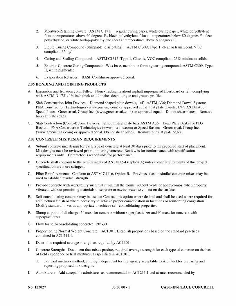
No. 123027 03 30 00 - 5 CAST-IN-PLACE CONCRETE
2. Moisture-Retaining Cover: ASTM C 171; regular curing paper, white curing paper, white polyethylene
film at temperatures above 60 degrees F., black polyethylene film at temperatures below 80 degrees F., clear
polyethylene, or white burlap-polyethylene sheet at temperatures above 60 degrees F.
3. Liquid Curing Compound (Strippable, dissipating): ASTM C 309, Type 1, clear or translucent. VOC
compliant, 350 g/l.
4. Curing and Sealing Compound: ASTM C1315, Type 1, Class A, VOC compliant, 25% minimum solids.
5. Exterior Concrete Curing Compound: Wax base, membrane forming curing compound, ASTM C309, Type
II, white pigmented.
6. Evaporation Retarder: BASF Confilm or approved equal.
2.06 BONDING AND JOINTING PRODUCTS
A. Expansion and Isolation Joint Filler: Nonextruding, resilient asphalt impregnated fiberboard or felt, complying
with ASTM D 1751, 1/4 inch thick and 4 inches deep; tongue and groove profile.
B. Slab Construction Joint Devices: Diamond shaped plate dowels, 1/4", ASTM A36; Diamond Dowel System:
PNA Construction Technologies (www.pna-inc.com) or approved equal; Flat plate dowels, 1/4", ASTM A36;
Speed Plate: Greenstreak Group Inc. (www.greenstreak.com) or approved equal. Do not shear plates. Remove
burrs at plate edges.
C. Slab Contraction (Control) Joint Devices: Smooth steel plate bars ASTM A36. Load Plate Basket or PD3
Basket: PNA Construction Technologies (www.pna-inc.com) or Speed Basket: Greenstreak Group Inc.
(www.greenstreak.com) or approved equal. Do not shear plates. Remove burrs at plate edges.
2.07 CONCRETE MIX DESIGN REQUIREMENTS
A. Submit concrete mix design for each type of concrete at least 30 days prior to the proposed start of placement.
Mix designs must be reviewed prior to pouring concrete. Review is for conformance with specification
requirements only. Contractor is responsible for performance.
B. Concrete shall conform to the requirements of ASTM C94 (Option A) unless other requirements of this project
specification are more stringent.
C. Fiber Reinforcement: Conform to ASTM C1116, Option B. Previous tests on similar concrete mixes may be
used to establish residual strength.
D. Provide concrete with workability such that it will fill the forms, without voids or honeycombs, when properly
vibrated, without permitting materials to separate or excess water to collect on the surface.
E. Self-consolidating concrete may be used at Contractor's option where desired and shall be used where required for
architectural finish or where necessary to achieve proper consolidation in locations or reinforcing congestion.
Modify standard mixes as appropriate to achieve self-consolidating properties.
F. Slump at point of discharge: 5" max. for concrete without superplasticizer and 9" max. for concrete with
superplasticizer.
G. Flow for self-consolidating concrete: 20"-30"
H. Proportioning Normal Weight Concrete: ACI 301. Establish proportions based on the standard practices
contained in ACI 211.1.
I. Determine required average strength as required by ACI 301.
J. Concrete Strength: Document that mixes produce required average strength for each type of concrete on the basis
of field experience or trial mixtures, as specified in ACI 301.
1. For trial mixtures method, employ independent testing agency acceptable to Architect for preparing and
reporting proposed mix designs.
K. Admixtures: Add acceptable admixtures as recommended in ACI 211.1 and at rates recommended by
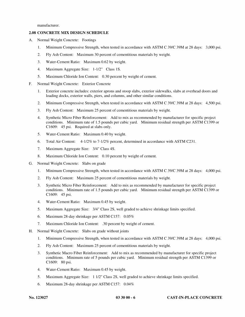
No. 123027 03 30 00 - 6 CAST-IN-PLACE CONCRETE
manufacturer.
2.08 CONCRETE MIX DESIGN SCHEDULE
A. Normal Weight Concrete: Footings
1. Minimum Compressive Strength, when tested in accordance with ASTM C 39/C 39M at 28 days: 3,000 psi.
2. Fly Ash Content: Maximum 30 percent of cementitious materials by weight.
3. Water-Cement Ratio: Maximum 0.62 by weight.
4. Maximum Aggregate Size: 1-1/2" Class 1S.
5. Maximum Chloride Ion Content: 0.30 percent by weight of cement.
F. Normal Weight Concrete: Exterior Concrete
1. Exterior concrete includes: exterior aprons and stoop slabs, exterior sidewalks, slabs at overhead doors and
loading docks, exterior walls, piers, and columns, and other similar conditions.
2. Minimum Compressive Strength, when tested in accordance with ASTM C 39/C 39M at 28 days: 4,500 psi.
3. Fly Ash Content: Maximum 25 percent of cementitious materials by weight.
4. Synthetic Micro Fiber Reinforcement: Add to mix as recommended by manufacturer for specific project
conditions. Minimum rate of 1.5 pounds per cubic yard. Minimum residual strength per ASTM C1399 or
C1609: 45 psi. Required at slabs only.
5. Water-Cement Ratio: Maximum 0.40 by weight.
6. Total Air Content: 4-1/2% to 7-1/2% percent, determined in accordance with ASTM C231.
7. Maximum Aggregate Size: 3/4" Class 4S.
8. Maximum Chloride Ion Content: 0.10 percent by weight of cement.
G. Normal Weight Concrete: Slabs on grade
1. Minimum Compressive Strength, when tested in accordance with ASTM C 39/C 39M at 28 days: 4,000 psi.
2. Fly Ash Content: Maximum 25 percent of cementitious materials by weight.
3. Synthetic Micro Fiber Reinforcement: Add to mix as recommended by manufacturer for specific project
conditions. Minimum rate of 1.5 pounds per cubic yard. Minimum residual strength per ASTM C1399 or
C1609: 45 psi.
4. Water-Cement Ratio: Maximum 0.45 by weight.
5. Maximum Aggregate Size: 3/4" Class 2S, well graded to achieve shrinkage limits specified.
6. Maximum 28-day shrinkage per ASTM C157: 0.05%
7. Maximum Chloride Ion Content: .30 percent by weight of cement.
H. Normal Weight Concrete: Slabs on grade without joints
1. Minimum Compressive Strength, when tested in accordance with ASTM C 39/C 39M at 28 days: 4,000 psi.
2. Fly Ash Content: Maximum 25 percent of cementitious materials by weight.
3. Synthetic Macro Fiber Reinforcement: Add to mix as recommended by manufacturer for specific project
conditions. Minimum rate of 5 pounds per cubic yard. Minimum residual strength per ASTM C1399 or
C1609: 80 psi.
4. Water-Cement Ratio: Maximum 0.45 by weight.
5. Maximum Aggregate Size: 1 1/2" Class 2S, well graded to achieve shrinkage limits specified.
6. Maximum 28-day shrinkage per ASTM C157: 0.04%

No. 123027 03 30 00 - 7 CAST-IN-PLACE CONCRETE
7. Maximum Chloride Ion Content: .30 percent by weight of cement.
2.09 SOURCE QUALITY CONTROL
A. Provide an independent testing laboratory to perform the following:
1. At the beginning of the concrete operations for the project and for each 1,000 yards of concrete delivered to
the project, test the fine and coarse aggregate gradation in accordance with ASTM C136 for conformance
with this specification.
2. Submit test results to the Architect.
B. Submit records showing that, within the previous year, the batch plant has been certified as meeting the
requirements of the National Concrete Ready Mix Association or the inspection checklist in ACI 311.4R and
conforms to:
1. Control, handling, and material storage requirements of Chapter 2 of ACI 304.
2. Measurement requirements of Chapter 3 of ACI 304 and that batching equipment is in good condition.
3. Batching tolerance requirements of Table 3.1.2 of ACI 304.
4. Inspection performed by a qualified independent inspector.
PART 3 EXECUTION
3.01 EXAMINATION
A. Verify lines, levels, and dimensions before proceeding with work of this section.
3.02 PREPARATION
A. Verify that anchors, seats, plates, reinforcement and other items to be cast into concrete are accurately placed,
positioned securely, and will not interfere with concrete placement.
B. Do not embed pipes other than non-aluminum electrical conduit or snow melting pipes in any structural concrete.
1. Any pipes embedded in concrete, even those meeting the guidelines given herein, are subject to acceptance
by Architect. Remove any unacceptable pipes.
2. Outside diameter of pipes placed in slabs and walls shall not exceed 25% of the thickness of the slab or wall
and shall be placed in groups of not more than 3. Space pipes within a group at not less than 4 diameters
clear. Space groups of pipes at not less than 48 diameters clear.
3. Maximum total dimension or area of pipes and their fittings embedded in concrete beams and columns shall
not exceed, at any location, 15% of least section dimension or 4% of the gross cross sectional area.
C. Where new concrete is to be bonded to existing or previously placed concrete, clean existing surface to remove
dust, dirt, grease, oil, curing compounds and other items that would be detrimental to bonding. Saturate existing
surface with clean water (8 hours minimum), remove excess water, and slush with a neat cement grout
immediately before placing new concrete.
D. Protect existing concrete work to be exposed to view and other finished materials from damage and staining
resulting from concreting operations. Cover sills, ledges and other surfaces with protective coverings as
necessary to protect the work.
E. Slabs on Grade:
1. Verify subgrade compaction tests have been performed and are accepted.
2. Verify subgrade is level and within acceptable tolerances.
3. Verify subgrade is substantially dry with no freestanding water, muddy spots, or soft spots and is free from
snow or ice.
4. Verify completion of all underfloor mechanical end electrical work.
5. Provide 3 inch minimum cover bottom and 3 inch minimum cover sides at electrical conduits and other

No. 123027 03 30 00 - 8 CAST-IN-PLACE CONCRETE
embedded items.
3.03 JOINTS
A. Locate slab on grade construction and control joints as given on Drawings and submit drawings showing proposed
locations. Cut joints as soon as concrete has hardened sufficiently to prevent aggregate dislodgement. Use a
"Soff Cut" saw to cut to a depth of 1 1/4" immediately after final finishing. Use a conventional saw to cut to a
depth of one-fourth the slab thickness or as shown on the drawings. Complete sawing within 12 hours of
placement.
B. Vertical construction joints in walls shall be a maximum of 80 feet on center and shall be located as shown on
structural drawings. Vertical control joints in wall shall be a maximum of 20 feet on center between construction
joints and shall be located as shown on the structural drawings. If locations are not shown, locate joints at edges
of piers integral with wall and near corners and in concealed locations where possible.
C. Locate construction joints for beams, slabs, joists and girders in the middle 1/3 of the span. Place so they do not
compromise the strength of the structure. Offset joints in a girder at least twice the beam width from a
beam-girder intersection.
D. Horizontal joints in walls and columns shall be at underside of slabs, beams and girders and at top of footings. At
least 24 hours shall elapse between placing concrete in a wall or column and placing concrete in an area supported
by the wall or column.
E. Reinforcing shall be continuous across construction joints. Provide dowels where detailed or requested. Joints in
walls shall be keyed with longitudinal keys at least 1-1/2 inches deep unless detailed otherwise.
3.04 CONCRETE MIXING
A. Transit Mixers: Comply with ASTM C 94/C 94M.
B. Use cooled or heated water in accordance with ACI 306 and 305.
C. Air-entraining and chemical admixtures, if approved, shall be charged into mixer as a solution and dispensed by an
automatic dispenser or similar metering device. Powdered admixtures shall be weighted or measured by volume
as recommended by the manufacturer. Superplasticizer may be added at the job site to maintain slump.
D. Two or more admixtures may be used in same concrete, provided such admixtures are added separately during
batching sequence. Admixtures used in combination shall retain full efficiency and have no deleterious effect on
concrete or on properties of each other.
E. For fiber reinforced concrete, introduce fibers to mix when recommended by fiber supplier to maximize
disbursement through the mix and to minimize balling of fibers.
F. Ready mixed concrete shall be transported to the site in watertight agitator or mixer trucks loaded not in excess of
rated capacities. Schedule and dispatch trucks from the batching point so that they shall arrive at the site of the
work just before the concrete is required to avoid excessive mixing of concrete while waiting.
G. Discharge at the site shall begin within one (1) hour after charging. Concrete may be used as long as it is of such
slump that it can be placed and properly consolidated without the addition of water to the batch (other than water
added prior to the start of discharge as given below). If elapsed time since batching exceeds 90 minutes, or if
drum has revolved more than 300 revolutions since batching, test air content, slump, and temperature for
conformance to this specification prior to placing. In no case shall the time between batching and complete
discharge exceed 120 minutes. Do not permit retempering of concrete. Discard concrete that has obtained its
initial set.
H. Do not add water after the initial introduction of the mixing water for the batch, except at the start of discharge,
subject to the conditions below. In this case, the producer may add water in an amount not exceeding that allowed
to achieve the design water/cement ratio. The drum blades shall then be turned an additional 30 revolutions
minimum at mixing speed. Water shall not be added to the batch at any later time. Reject concrete if water is
added and these conditions are not met.
1. The measured slump of the concrete is less than that specified in the mix design.
2. No more than 60 minutes have elapsed from the time of batching.

No. 123027 03 30 00 - 9 CAST-IN-PLACE CONCRETE
3. The ready-mix plant is notified and approves.
4. Truck tickets indicate maximum amount of water to be added.
5. Water is added in a manner to control volume.
6. Special Inspector is notified, if concrete placement requires inspection.
I. Maximum concrete temperature delivered to Project site shall be 85 degrees F.
J. To use materials other than those accepted originally, or if the materials from the source originally accepted
change in characteristics, make additional tests with proposed new materials that will verify production of concrete
meeting with the stated requirements without causing objectionable change in the color or appearance of the
structure. Pay the testing agency for these additional tests. Do not use concrete made from such different
materials until the Architect has given his approval.
K. If, during the progress of the work, it is impossible to secure concrete of the required workability and strength with
the materials being furnished by the Vendor, the Architect may order such changes in the proportions or materials,
or both, as may be necessary to secure the desired properties, subject to the stated requirements. Make any
changes so ordered without extra compensation.
3.05 PLACING CONCRETE
A. Place concrete in accordance with ACI 301. Follow recommended practice of ACI 304R.
B. Place concrete for floor slabs following recommended practices of ACI 302.1R.
C. Do not place in rain, sleet or snow unless exposed concrete surface is protected from moisture.
D. Ensure reinforcement, inserts, and embedded parts will not be disturbed during concrete placement.
E. Repair underslab vapor retarder damaged during placement of concrete reinforcing. Repair with vapor retarder
material; lap over damaged areas minimum 6 inches and seal watertight.
F. Separate slabs on grade from vertical surfaces with joint filler.
G. Install joint devices in accordance with manufacturer's instructions.
H. Install construction joint devices in coordination with floor slab pattern placement sequence. Set top to required
elevations. Secure to resist movement by wet concrete.
I. Maintain records of concrete placement. Record date, location, quantity, air temperature, and test samples taken.
J. Place concrete continuously between predetermined expansion, control, and construction joints.
K. Do not interrupt successive placement; do not permit cold joints to occur.
L. If, for any reason, the concrete pour is delayed for more than 45 minutes, bulkhead pour at last acceptable
construction joint. Immediately remove excess concrete and clean all forms and in situ concrete surfaces.
M. Do not permit concrete to drop more than 4 feet from its point of release to mixers, hoppers, or conveyances. Use
tremmies, chutes, or pumps as necessary to place columns and walls.
N. Deposit concrete in wall forms in layers not greater than 24 inches in depth. Consolidate each layer before the
succeeding layer is placed.
O. Place concrete as near as possible to its final position to prevent segregation. Do not use vibrators to transport
concrete.
P. Immediately remove concrete spilled on existing surfaces.
Q. Exercise care in placing concrete over waterproof membranes to avoid damaging the membrane. Report damage
immediately, and do not proceed until the damage is repaired.
R. Place slabs on grade according to submitted, approved joint location plan.
S. Concrete at tops of forms: Strike concrete at top of wall, footing, and pier forms. Smooth and float to texture
comparable to adjacent formed surfaces.

No. 123027 03 30 00 - 10 CAST-IN-PLACE CONCRETE
3.06 CONSOLIDATION
A. Consolidation of concrete shall conform to ACI 301, unless modified herein.
B. Follow recommended practices of ACI 309, unless modified herein.
C. Consolidate concrete using internal vibrators.
D. Maintain a spare vibrator at the Project Site during all placing operations.
3.07 SELF-LEVELING CEMENT BASED UNDERLAYMENT
A. Clean surface of oil, grease, dirt, dust, curing compounds and laitance to sound concrete and according to
manufacturers written instructions. Apply primer as recommended by manufacturer.
B. Mix in accordance with manufacturers instructions. Add aggregate if required due to underlayment thickness.
C. Pour over substrate and spread per manufacturers instructions.
D. Protect from foot traffic until underlayment is fully cured.
3.08 CONCRETE FINISHING
A. Concrete Finish Schedule
1. Exterior platforms, aprons, ramps, loading docks, and garage slabs: Broom finish.
B. Formed Surfaces
1. Repair surface defects, immediately after removing formwork.
2. Provide finishes per ACI 301 as scheduled and to the following tolerances.
3. Rough Form Finish: Rub down or chip off fins or other raised areas 1/2 inch or more in height. Rough form
finish per ACI 301. Class C surface per ACI 117.
4. Smooth Form Finish: Rub down or chip off and smooth fins or other raised areas 1/8 inch or more in height.
Smooth form finish per ACI 301. Class B surface per ACI 117.
C. Unformed Surfaces
1. Provide finishes per ACI 301 as scheduled herein or noted on Drawings and to the following tolerances.
a. Troweled Finish: Moderately flat tolerance per ACI 117. Slope slab to floor drains.
b. Flat Troweled Finish: Flat tolerance per ACI 117
c. Scratched Finish: Conventional tolerance per ACI 117.
d. Broom Finish: Moderately flat tolerance per ACI 117.
e. Floated Finish: Conventional tolerance per ACI 117.
f. Non-Slip Finish: Broom finish or a troweled finish with a "dry shake" abrasive application, wet
abrasive prior to installation, and apply at a rate not less than 25 pounds per 100 square feet.
Moderately flat tolerance.
2. Provide finishes per ACI 301 as scheduled and to the following tolerances (F Numbers) per ACI 117 and
measured according to ASTM E1155.
a. Troweled Finish: Moderately flat tolerance.
1) F(F): Specified Overall Value of 25; Minimum Localized Value of 15.
2) F(L): Specified Overall Value of 20; Minimum Localized Value of 12.
b. Flat Troweled Finish: Flat tolerance
1) F(F): Specified Overall Value of 35; Minimum Localized Value of 21.
2) F(L): Specified Overall Value of 25; Minimum Localized Value of 15.
c. Scratched Finish: Conventional tolerance.
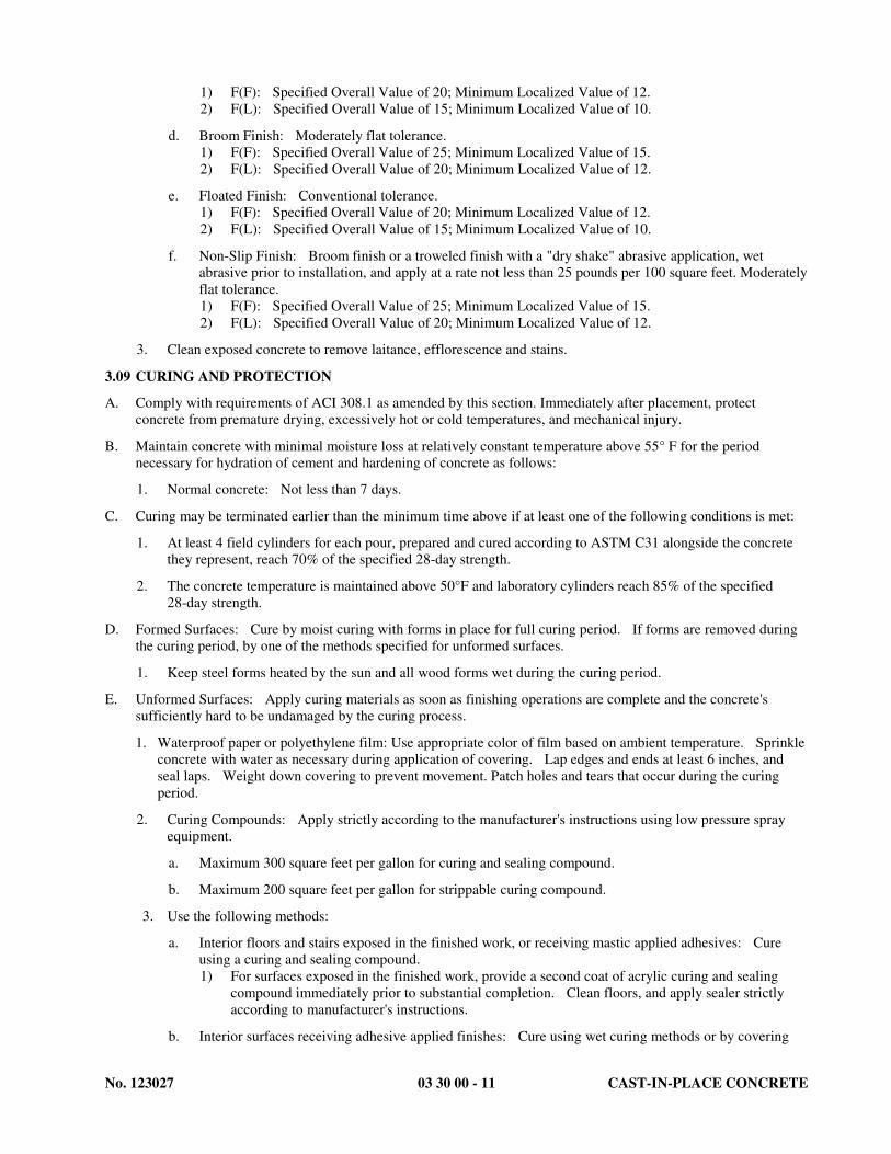
No. 123027 03 30 00 - 11 CAST-IN-PLACE CONCRETE
1) F(F): Specified Overall Value of 20; Minimum Localized Value of 12.
2) F(L): Specified Overall Value of 15; Minimum Localized Value of 10.
d. Broom Finish: Moderately flat tolerance.
1) F(F): Specified Overall Value of 25; Minimum Localized Value of 15.
2) F(L): Specified Overall Value of 20; Minimum Localized Value of 12.
e. Floated Finish: Conventional tolerance.
1) F(F): Specified Overall Value of 20; Minimum Localized Value of 12.
2) F(L): Specified Overall Value of 15; Minimum Localized Value of 10.
f. Non-Slip Finish: Broom finish or a troweled finish with a "dry shake" abrasive application, wet
abrasive prior to installation, and apply at a rate not less than 25 pounds per 100 square feet. Moderately
flat tolerance.
1) F(F): Specified Overall Value of 25; Minimum Localized Value of 15.
2) F(L): Specified Overall Value of 20; Minimum Localized Value of 12.
3. Clean exposed concrete to remove laitance, efflorescence and stains.
3.09 CURING AND PROTECTION
A. Comply with requirements of ACI 308.1 as amended by this section. Immediately after placement, protect
concrete from premature drying, excessively hot or cold temperatures, and mechanical injury.
B. Maintain concrete with minimal moisture loss at relatively constant temperature above 55° F for the period
necessary for hydration of cement and hardening of concrete as follows:
1. Normal concrete: Not less than 7 days.
C. Curing may be terminated earlier than the minimum time above if at least one of the following conditions is met:
1. At least 4 field cylinders for each pour, prepared and cured according to ASTM C31 alongside the concrete
they represent, reach 70% of the specified 28-day strength.
2. The concrete temperature is maintained above 50°F and laboratory cylinders reach 85% of the specified
28-day strength.
D. Formed Surfaces: Cure by moist curing with forms in place for full curing period. If forms are removed during
the curing period, by one of the methods specified for unformed surfaces.
1. Keep steel forms heated by the sun and all wood forms wet during the curing period.
E. Unformed Surfaces: Apply curing materials as soon as finishing operations are complete and the concrete's
sufficiently hard to be undamaged by the curing process.
1. Waterproof paper or polyethylene film: Use appropriate color of film based on ambient temperature. Sprinkle
concrete with water as necessary during application of covering. Lap edges and ends at least 6 inches, and
seal laps. Weight down covering to prevent movement. Patch holes and tears that occur during the curing
period.
2. Curing Compounds: Apply strictly according to the manufacturer's instructions using low pressure spray
equipment.
a. Maximum 300 square feet per gallon for curing and sealing compound.
b. Maximum 200 square feet per gallon for strippable curing compound.
3. Use the following methods:
a. Interior floors and stairs exposed in the finished work, or receiving mastic applied adhesives: Cure
using a curing and sealing compound.
1) For surfaces exposed in the finished work, provide a second coat of acrylic curing and sealing
compound immediately prior to substantial completion. Clean floors, and apply sealer strictly
according to manufacturer's instructions.
b. Interior surfaces receiving adhesive applied finishes: Cure using wet curing methods or by covering

No. 123027 03 30 00 - 12 CAST-IN-PLACE CONCRETE
with waterproof paper or polyethylene film.
1) Curing and sealing compound may be used upon receipt of a letter from the adhesive manufacturer
that this compound is compatible with the adhesive.
2) Strippable curing compound may be used provided it is completely removed prior to installation of
adhesive.
c. Exterior concrete: Cure using exterior concrete curing compound.
d. Composite (bonded) topping: Cure with moisture cover curing material. Maintain curing for full
seven days. Early termination is not permitted.
e. All other unformed surfaces: Cure using a strippable curing compound, by wet curing methods, or by
covering with waterproof paper or polyethylene film.
1) Remove strippable curing compound prior to installation of cementitious or adhered finishes.
4. Protect concrete from excessive changes in temperature during the curing period and at the termination of the
curing process. Changes in the temperature of the concrete shall be as uniform as possible and shall not
exceed 5° F in any one hour or 50° F in any 24 hour period.
3.10 HOT WEATHER CONCRETING
A. Apply recommended practices of ACI 305R when temperature and humidity will affect placing and finishing or
may cause plastic shrinkage cracking.
B. Wet or fog forms and reinforcing immediately prior to placement to bring temperature to ambient conditions.
C. The following additional requirements apply when the temperature exceeds 70° F.
1. Provide concrete meeting the following temperature requirements:
a. Wind Speed 0-10 mph: Maximum Concrete Temperature 80° F.
b. Wind Speed 10-15 mph: Maximum Concrete Temperature 75° F.
c. Wind Speed 15-20 mph: Maximum Concrete Temperature 70° F.
d. Wind Speed 20-25 mph: Maximum Concrete Temperature 65° F.
2. Do not place concrete if the relative humidity is less than 30%
3. Do not place concrete without windbreaks if the wind speed at the slab elevation is greater than 25 mph.
4. Maintain surface moisture during the period between placement and final finishing by using fog sprayers,
evaporation reducing materials, or shade (individually or in combination).
3.11 COLD WEATHER CONCRETING
A. Concrete placed during cold weather shall conform to the requirements of ACI 306.1.
B. Cold weather is defined as 3 or more successive days when the average daily outdoor temperature is less than 40
degrees F.
C. All surfaces, including subgrade and reinforcing shall be above 35 degrees F. prior to placing concrete. Surfaces
shall not be more than 10 degrees warmer than the minimum concrete temperatures required by ACI 306.1.
D. Maintain cold weather protection for the following duration but not less than the duration specified in "Curing and
Protection" above:
1. Maintain protection for a minimum of 48 hours after placement of concrete.
2. Maintain protection for columns and supported slabs until at least 4 field cylinders, prepared and cured in
accordance with ASTM C31, reach 85 percent of the specified 28-day strength, or, laboratory cured cylinders
reach the specified 28-day strength.
E. Submit detailed procedures for cold weather concreting for engineer's information only.
F. Follow recommended practices of ACI 306R. Subject to other requirements of this section, a non-chloride

No. 123027 03 30 00 - 13 CAST-IN-PLACE CONCRETE
accelerator may be used to normalize initial set and for early strength gain.
3.12 PERIMETER INSULATION
A. Install over non-waterproofed foundation wall.
B. Place on face of wall to a aminimum depth of four feet below grade unless shown deeper on drawings.
C. Secure to substrate with manufacturer-recommended adhesive until backfill is placed.
D. If insulation is to remain uncovered for more than 30 days, protect from UV exposure with opaque covering.
3.13 FIELD QUALITY CONTROL
A. Provide free access to concrete operations at project site and cooperate with appointed firm.
B. Structural Testing and Special Inspection
1. Structural Testing and Special Inspection shall be performed by qualified parties as specified herein, and in
accordance with the provisions of Section 01 4533.
2. Personnel Qualifications
a. Testing Technician: Technical I - ACI Certified Concrete Field Testing Technician, Grade I, employed
by a testing laboratory with C.C.R.L. certification at the National Bureau of Standards, under the direct
supervision of a licensed civil/structural engineer. The licensed engineer shall review and approve all
reports.
b. Special Inspector – Structural I: ICBO Certified Concrete Inspector, ACI Concrete Construction
Inspector, or a graduate civil/structural engineer, or other personnel acceptable to the Structural
Engineer of Record (SER), with experience in the design of structural systems of this type. Inspections
shall be performed under the direct supervision of a licensed structural engineer, as defined in Section
01 4533. The licensed engineer shall review and approve all inspection reports.
3. The Owner will provide the following tests and inspections:
a. Tests for cast in place concrete. Qualifications: Technical I.
1) Compression test specimens: ASTM C31. One set of four standard cylinders of concrete for
each compressive strength test. Mold and store cylinders for laboratory cured specimens.
2) Compressive strength tests: ASTM C39. One set of four cylinders for each day's pour between
one and 25 cubic yards. If a day's pour exceeds 25 cubic yards, one set of four cylinders for each
additional 50 cubic yards, or fraction thereof. One specimen tested at 7 days for information, two
at 28 days for acceptance, and one specimen retained in reserve for later testing if required.
(When frequency of testing will provide less than five strength tests for a given class of concrete,
conduct at least five strength tests from randomly selected batches. If fewer than five batches are
used, conduct one test from each batch.)
3) For post tensioned concrete, make and test an additional cylinder at three days to verify strength
prior to stressing.
4) Slump: ASTM C143. One test at point of discharge for each set of compression test specimens;
additional tests when concrete consistency appears to have changed.
5) Air entrainment: ASTM C231. Test the first batch of air entrained concrete and one additional
test for each set of compression test specimens.
6) Concrete temperature: Test hourly when air temperature is below 40°F or above 80°F and each
time a set of compression test specimens is made.
b. Concrete mix verification. Qualifications: Technical I. Verify the following:
1) Mixer truck trip ticket conforms to approved mix design.
2) Total water added to mix on site does not exceed that allowed by concrete mix design.
3) Concrete quality is indicative of adequate mixing time, consistency, and relevant time limits.
c. Observe preparation for and placement of all concrete, excluding slabs on grade, strip footings without
transverse reinforcement, and unbonded topping slabs. Additional exclusions may be noted on the
structural drawings. Special Inspector must be present during entire concrete pour. Qualifications:
Structural I. Verify the following:
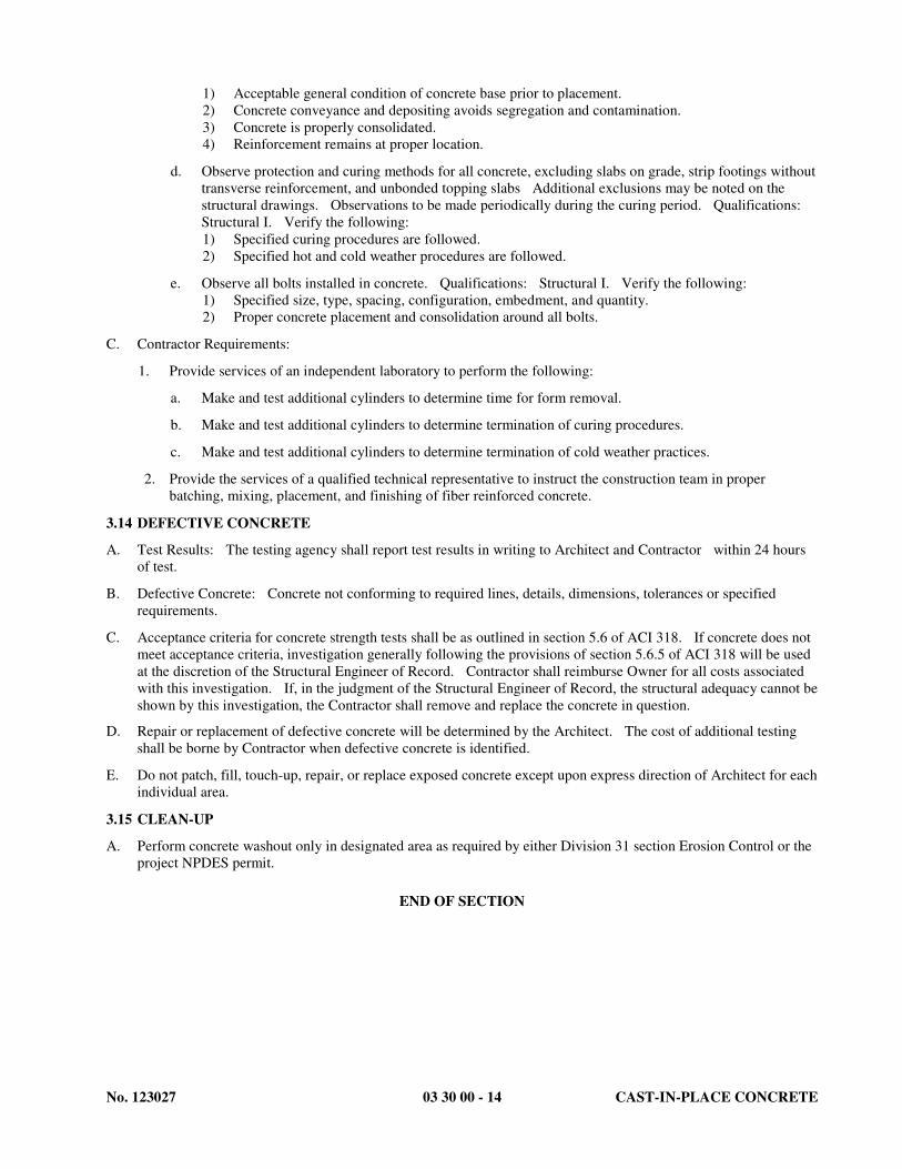
No. 123027 03 30 00 - 14 CAST-IN-PLACE CONCRETE
1) Acceptable general condition of concrete base prior to placement.
2) Concrete conveyance and depositing avoids segregation and contamination.
3) Concrete is properly consolidated.
4) Reinforcement remains at proper location.
d. Observe protection and curing methods for all concrete, excluding slabs on grade, strip footings without
transverse reinforcement, and unbonded topping slabs Additional exclusions may be noted on the
structural drawings. Observations to be made periodically during the curing period. Qualifications:
Structural I. Verify the following:
1) Specified curing procedures are followed.
2) Specified hot and cold weather procedures are followed.
e. Observe all bolts installed in concrete. Qualifications: Structural I. Verify the following:
1) Specified size, type, spacing, configuration, embedment, and quantity.
2) Proper concrete placement and consolidation around all bolts.
C. Contractor Requirements:
1. Provide services of an independent laboratory to perform the following:
a. Make and test additional cylinders to determine time for form removal.
b. Make and test additional cylinders to determine termination of curing procedures.
c. Make and test additional cylinders to determine termination of cold weather practices.
2. Provide the services of a qualified technical representative to instruct the construction team in proper
batching, mixing, placement, and finishing of fiber reinforced concrete.
3.14 DEFECTIVE CONCRETE
A. Test Results: The testing agency shall report test results in writing to Architect and Contractor within 24 hours
of test.
B. Defective Concrete: Concrete not conforming to required lines, details, dimensions, tolerances or specified
requirements.
C. Acceptance criteria for concrete strength tests shall be as outlined in section 5.6 of ACI 318. If concrete does not
meet acceptance criteria, investigation generally following the provisions of section 5.6.5 of ACI 318 will be used
at the discretion of the Structural Engineer of Record. Contractor shall reimburse Owner for all costs associated
with this investigation. If, in the judgment of the Structural Engineer of Record, the structural adequacy cannot be
shown by this investigation, the Contractor shall remove and replace the concrete in question.
D. Repair or replacement of defective concrete will be determined by the Architect. The cost of additional testing
shall be borne by Contractor when defective concrete is identified.
E. Do not patch, fill, touch-up, repair, or replace exposed concrete except upon express direction of Architect for each
individual area.
3.15 CLEAN-UP
A. Perform concrete washout only in designated area as required by either Division 31 section Erosion Control or the
project NPDES permit.
END OF SECTION

No. 123027 05 12 00 - 1 STRUCTURAL STEEL FRAMING
SECTION 05 1200
STRUCTURAL STEEL FRAMING
PART 1 GENERAL
1.01 RELATED DOCUMENTS
A. Drawings, Details of Construction, and General Provisions of the Contract, including General and Supplementary
Conditions and Division - 1 Specification Sections, apply to this Section.
1.02 SECTION INCLUDES
A. Base plates and headed studs.
1.03 RELATED REQUIREMENTS
A. Section 01 4533 - Structural Testing and Special Inspection.
B. Section 03 1510 - Post-Installed Anchors.
1.04 REFERENCE STANDARDS
A. AISC (MAN) - Steel Construction Manual; American Institute of Steel Construction, Inc.; 2005.
B. AISC 360 - Specification for Steel Buildings; American Institute of Steel Construction, Inc.; 2005.
C. AISC S303 - Code of Standard Practice for Steel Buildings and Bridges; American Institute of Steel Construction,
Inc.; 2005.
D. AISC S348 (Research Council on Structural Connections) - Specification for Structural Joints Using ASTM A325
or A490 Bolts; 2004.
E. ASTM A 36/A 36M - Standard Specification for Carbon Structural Steel; 2005.
F. ASTM A 53/A 53M - Standard Specification for Pipe, Steel, Black and Hot-Dipped, Zinc-Coated, Welded and
Seamless; 2007.
G. ASTM A 108 - Standard Specification for Steel Bar, Carbon and Alloy, Cold Finished; 2007.
H. ASTM A 123/A 123M - Standard Specification for Zinc (Hot-Dip Galvanized) Coatings on Iron and Steel
Products; 2002.
I. ASTM A 307 - Standard Specification for Carbon Steel Bolts and Studs, 60 000 PSI Tensile Strength; 2007b.
J. ASTM A 325 - Standard Specification for Structural Bolts, Steel, Heat Treated, 120/105 ksi Minimum Tensile
Strength; 2009.
K. ASTM A 325M - Standard Specification for Structural Bolts, Steel, Heat Treated 830 MPa Tensile Strength
(Metric); 2009.
L. ASTM A496-02 - Steel Wire, Deformed, for Concrete Reinforcement
M. ASTM A 500/A 500M - Standard Specification for Cold-Formed Welded and Seamless Carbon Steel Structural
Tubing in Rounds and Shapes; 2007.
N. ASTM A 563 - Standard Specification for Carbon and Alloy Steel Nuts; 2007a.
O. ASTM A 563M - Standard Specification for Carbon and Alloy Steel Nuts [Metric]; 2007.
P. ASTM A780 - Standard Specification for Repair of Damaged and Uncoated Areas of Hot-Dip Galvanized
Coatings; 2001
Q. ASTM A 992/A 992M - Standard Specification for Structural Steel Shapes; 2006a.
R. ASTM E 709 - Standard Guide for Magnetic Particle Testing; 2008.
S. ASTM F 436 - Standard Specification for Hardened Steel Washers; 2009.

No. 123027 05 12 00 - 2 STRUCTURAL STEEL FRAMING
T. ASTM F 959 - Standard Specification for Compressible-Washer-Type Direct Tension Indicators for Use with
Structural Fasteners; 2007a.
U. ASTM F 1554 - Standard Specification for Anchor Bolts, Steel, 36, 55, and 105-ksi Yield Strength; 2007a.
V. ASTM F1852 - Twist Off Type Tension Control Structural Bolt/Nut/Washer Assemblies, Steel, Heat Treated,
120/105 ksi Minimum Tensile Strength; 2002
W. AWS A2.4 - Standard Symbols for Welding, Brazing, and Nondestructive Examination; American Welding
Society; 2007.
X. AWS D1.1/D1.1M - Structural Welding Code - Steel; American Welding Society; 2008.
Y. SSPC-Paint 20 - Zinc-Rich Primers (Type I, "Inorganic," and Type II, "Organic"); Society for Protective Coatings;
2002 (Ed. 2004).
1.05 SUBMITTALS
A. See Section 01 3000 - Administrative Requirements, for submittal procedures.
B. Shop Drawings:
1. Review the Contract Documents prior to preparing shop drawings to determine if the structure is in conflict
with OSHA requirements or any other safety regulation. Notify the Architect if any conflicts are noted. Do
not prepare shop drawings affected by the conflict until the conflict is resolved.
2. Prepare complete shop and setting drawings based on referenced AISC Specifications.
3. Indicate profiles, sizes, spacing, locations of structural members, openings, attachments, and fasteners.
4. Indicate type and location of shop and field connections. Detail all required field welds.
5. Indicate cambers.
6. Indicate welded connections with AWS A2.4 welding symbols. Indicate net weld lengths.
7. Clearly indicate members considered to be Architecturally Exposed Structural Steel (AESS) and detail
members and connections consistent with AESS criteria included in this specification section.
8. If shop drawings are resubmitted after the original review, identify all changes made to the shop drawings
after the original submittal with clouds or similar markings.
C. Submit AISC Quality Certification Program certificates (for reduction in shop special inspections only if the
fabricator is so certified) and welder qualifications to the Special Inspector-Technical.
D. Welders Certificates: Certify welders employed on the Work, verifying AWS qualification within the previous 12
months.
1.07 QUALITY ASSURANCE
A. Fabricate structural steel members in accordance with AISC "Manual of Steel Construction".
B. Fabricator: Company specializing in performing the Work of this Section with minimum five years of
documented experience. Fabrication plant shall be certified in category I or II according to the requirements of
the AISC Quality Certification Program and shall be acceptable to and approved in writing by the structural
engineer, Architect, and building official. Do not proceed with steel fabrication until the Architect has provided
final written approval.
1. As an alternative to fabricator certification, the Contractor may pay for full time inspection during the
fabrication of the Project steel. This inspection shall be conducted by the Owner's inspection company at the
fabrication plant. In addition, the fabrication plant shall also be acceptable to and approved in writing by the
Structural Engineer, Architect, and Building Official. Do not proceed with the Work until the A/E has
provided final written approval.
C. Design connections not detailed on the drawings under direct supervision of a Professional Structural Engineer
experienced in design of this work and licensed in the State in which the Project is located.

No. 123027 05 12 00 - 3 STRUCTURAL STEEL FRAMING
D. Codes and Standards:
1. AISC - Manual of Steel Construction.
2. AISC 360 - Specification for Structural Steel Buildings
3. AISC - Code of Standard Practice for Steel Buildings and Bridges
4. AWS D1.1.
5. AISC S348 - Specification for Structural Joints Using ASTM A325 or A490 Bolts
6. SSPC - SSPC Painting Manual - Volume 2
E. Provide personnel qualified according to AWS D1.1 for all shop and field welding.
1.08 PROJECT/SITE CONDITIONS
A. Verify all dimensions given on the Drawings and make such field measurements as are necessary to lay out the
work properly and assure proper elevations. Be fully responsible for accuracy of all measurements and laying out
of the work.
B. Upon execution of a licensing agreement and payment of a service fee determined by engineer, the engineer will
make electronic versions of structural framing plans available to the contractor for the purpose of preparing
erection drawings.
PART 2 PRODUCTS
2.01 MATERIALS
A. Steel Angles, Plates, and Channels: ASTM A 36/A 36M.
B. Steel W Shapes and Tees: ASTM A 992/A 992M.
C. Cold-Formed Hollow Structural Sections: ASTM A 500, Grade B.
D. Pipe: ASTM A 53/A 53M, Grade B, Finish black.
E. Shear Stud Connectors: Made from ASTM A 108 Grade 1015 bars per AWS D1.1..
F. Structural Bolts and Nuts: Carbon steel, ASTM A 307, Grade A.
G. High-Strength Bolts, Nuts, and Washers: ASTM A 325 (ASTM A 325M), Type 1, medium carbon, plain.
1. Tension control bolts meeting ASTM F1852 are also acceptable.
H. Unheaded Anchor Rods: ASTM F 1554, Grade 36, plain, with matching ASTM A 563 or A 563M nuts and
ASTM F 436 Type 1 washers. Hot dip galvanize where noted.
I. Load Indicator Washers: Provide washers complying with ASTM F 959 at all connections requiring
high-strength bolts. Not required if tension control bolts are used.
J. Welding Materials: AISC Specification A35 and referenced AWS specifications, type required for materials
being welded, E70 electrodes.
K. Sliding Bearing Plates: 3/32" glass-filled PTFE bonded to 10 gage steel back-up plate. Size of element shown
on drawings. Flourogold: FC 1010-CS1/2L; Seismic Energy Products; (www.sepbearings.com) or Con-Slide:
09CSA 13CS 50L; Con-Serv (www.con-servinc.com)
L. Shop and Touch-Up Primer: Fabricator's standard, compatible with finish coatings, complying with VOC
limitations of authorities having jurisdiction.
M. Touch-Up Primer for Galvanized Surfaces: SSPC-Paint 20, Type I - Inorganic, complying with VOC limitations
of authorities having jurisdiction.
N. Post-installed anchors: See Section 03 1510
O. Deformed Bar Anchors: ASTM A496, AWS D.1, Chapter 7, arc stud welded.

No. 123027 05 12 00 - 4 STRUCTURAL STEEL FRAMING
2.02 FABRICATION
A. Fabricate according to referenced AISC publications.
B. Shop fabricate to greatest extent possible.
C. Do not substitute sections or modify details without written approval of the Structural Engineer. Provide
full-length pieces between connections or splices indicated on the drawings. Do not permit built-up lengths. Do
not use warped or damaged sections.
D. Design shop and field connections unless detailed on the Drawings. Use standard connections as shown in Part 9
of the AISC Manual where possible. Bolt field connections, unless otherwise indicated on the Drawings.
E. Perform bracing, blocking, cutting, fitting, drilling, tapping, welding, punching, etc., as required to complete work
and to join work of others. Weld clip angles and plates to beams and punch holes for fastening work of other
trades as shown on the Drawings.
F. Furnish anchor bolts of size and type shown on the drawings for all field connections to be permanently bolted to
concrete or masonry.
2.03 FINISH
A. Prepare structural component surfaces in accordance with SSPC SP 3 unless otherwise indicated.
B. Prepare faying surfaces at slip-critical bolted connections according to the requirements of AISC S348.
C. Shop prime structural steel members to a DFT of 2.0 - 3.5 mils. Do not prime surfaces that will be fireproofed or
field welded.
D. Galvanize structural steel exposed to weather, lintels in exterior masonry walls, embedded in concrete (exterior or
interior), and shelf angles and plates in exterior masonry walls to comply with ASTM A123/A123M
1. Prepare items to be galvanized in accordance with ASTM A385.
2. Close and seal weld vent holes in pipes, tubes, and other closed members. Touch up damaged areas using
procedures and products from ASTM A780.
2.04 SOURCE QUALITY CONTROL
A. If Fabricator is not a Category I AISC certified fabricator, see field quality control section of Part 3 for special
inspection requirements of shop fabricated work.
PART 3 EXECUTION
3.01 EXAMINATION
A. Verify that conditions are appropriate for erection of structural steel and that the work may properly proceed.
3.02 ERECTION
A. Erect structural steel in compliance with AISC "Code of Standard Practice for Steel Buildings and Bridges".
B. Allow for erection loads, and provide sufficient temporary bracing to maintain structure in safe condition, plumb,
and in true alignment until completion of erection and installation of permanent bracing.
C. Exercise care in handling structural steel during unloading, storage, and erection to prevent bends, twists, or other
damage.
D. Place structural steel stored at the site on substantial shores or blocking. Provide shores or blocking of sufficient
size and strength to prevent any part of the steel from touching the ground.
E. Remove dirt, oil, loose scale, burrs, pits, paint and other defects that would prevent solid seating of parts.
F. Field weld components indicated on shop drawings.
G. Use carbon steel bolts only for temporary bracing during construction, unless otherwise specifically permitted on
drawings. Install high-strength bolts in accordance with AISC "Specification for Structural Joints Using ASTM
A325 or A490 Bolts".

No. 123027 05 12 00 - 5 STRUCTURAL STEEL FRAMING
H. Where A307 bolts are used, tighten to a snug tight fit as obtained with the full effort of a man using an ordinary
spud wrench. Verify that all parts are in contact. Use self-locking nuts or upset bolt threads to prevent nuts from
bracing off.
I. Where A325 bolts are used, tighten bolts and provide washers in accordance with "Specification for Structural
Joints Using ASTM A325 or A490 Bolts". Use tension control bolts or direct tension indicators for slip-critical
(SC) and fully tensioned bolts (FT).
J. Pre-heat material to be welded and maintain interpass temperatures as required. Do not weld below 0 degrees F.
K. Remove all ceramic welding ferrules from shear studs.
L. Do not cut steel or enlarge holes without written approval of the Structural Engineer.
M. Do not field cut or alter structural members without approval of Architect and Structural Engineer.
N. After erection, prime welds, abrasions, and surfaces not shop primed, except surfaces to be in contact with
concrete or specified to be unprimed.
O. Repair or replace structural steel damaged during shipment, unloading, or erection at no cost to the Owner.
P. Install expansion and adhesive anchors in strict accordance with manufacturer’s recommendations.
3.03 CLEANING AND REPAIR
A. After erection and welding of steel, remove clay, mud or other foreign materials from all members.
B. Apply a field touch-up coat of paint on all welded connections and damaged areas using the same color and type of
paint used on the shop coat.
C. Repair damaged galvanized members with procedures and products from ASTM A780.
3.04 FIELD QUALITY CONTROL
A. Structural Testing and Special Inspection
1. Structural Special Inspection shall be performed by qualified parties as specified herein, and in accordance
with the provision of Section 01 4533.
2. If special inspection of Fabricator's work is required, special inspector may test and inspect structural steel at
plant before shipment.
3. Definitions:
a. ASNT - American Society for Non-Destructive Testing
b. CAWI - American Welding Society Certified Associate Weld Inspector
c. CWI - American Welding Society Certified Weld Inspector
4. Personnel Qualifications
a. Special Inspector Technical I: CAWI or ASNT Level I, employed by a testing agency and supervised
by a CWI or ASNT Level III with a minimum of 10 years experience.
b. Special Inspector Technical II: CAWI with minimum 3 years experience or ASNT Level II, employed
by a testing agency and supervised by a CWI or ASNT Level III with a minimum of 10 years
experience.
c. Special Inspector – Structural I: Graduate civil/structural engineer, or other personnel acceptable to the
SER, with experience in design of structural systems of the project type. Inspections shall be
performed under the direct supervision of a licensed structural engineer, as defined in Section 01 4533.
The licensed engineer shall review and approve all inspection reports.
d. Individuals performing welding inspection must be AWS certified.

No. 123027 05 12 00 - 6 STRUCTURAL STEEL FRAMING
5. The Owner will provide the following tests and inspections:
a. Shop Fabricated Work: Perform tests and inspections required below, except bolt and welding
inspections may be reduced or deleted, if fabrication shop satisfies AISC Quality Certification Program
- Category I, or more stringent criteria, or is approved by Building Official and SER.
b. Test high strength bolted connections according to the requirements of RCSC "Specification for
Structural Joints Using ASTM A325 or ASTM A490 Bolts", and as follows:
1) Preparation: Visually inspect mating surfaces and bolt type for all bolted connections for general
conformance with the contract documents prior to bolting. Qualifications: Technical II.
2) Slip Critical Bolts and Fully Tensioned Bolts: Visually observe all connections. Verify that all
plies of connected elements have been brought into contact. Verify all tips are removed from
"twist-off" bolts or direct tension indicators show fully tensioned bolts. Qualifications:
Technical II.
3) Bearing Bolts: Visually observe all connections to confirm all plies of connected elements have
been brought into contact. (Applies only to bolts designed with threads included in failure plane;
all other bolts require testing as for fully tensioned bolts.) Qualifications: Technical II.
c. Welding Procedures and Preparation: Qualifications: Technical II. Verify the following:
1) Qualifications of all welders as AWS certified.
2) Proposed welding procedures and materials.
3) Adequate preparation of fraying surfaces.
4) Preheat and interpass temperatures of steel, proper technique and sequence of welding, and
cleaning and number of passes.
d. Test and inspect welding as follows
1) Fillet Welds: Visually inspect 100% of all fillet welds, for size, length, and quality, per AWS
D1.1. Qualifications: Technical II.
2) Partial Penetration Welds: Test 100% of all partial penetration welds exceeding 5/16 inch, using
Ultrasonic Testing per AWS D1.1, Section 6. Visually inspect 100 % and test 25% of all
penetration welds less than 5/16 inch using Magnetic Particle Testing per ASTM E 709 performed
on root pass and on finished weld. Qualifications: Technical II.
3) Full Penetration Welds: Test 100% of all full penetration welds exceeding 5/16 inch, using
Ultrasonic Testing per AWS D1.1 Section 6. Visually inspect 100% and test 25% of all full
penetration welds less that 5/16 inch, using Magnetic Particle Testing per ASTM E 709 performed
on root pass and on finished weld. Qualifications: Technical II.
e. Stud Shear Connector Welds: Sound and visually inspect 100% of installed studs for full 360° flash.
Test all questionable not showing full 360° flash by bending studs to 15° from vertical, away from weld
discontinuity, per AWS D1.1, Section 7. Randomly test 15% of studs welded through deck and 5% of
studs welded to bare steel by bending to 15° from vertical. Qualifications: Technical II.
f. Submittals: Verify mill test reports and other submitted documentation for compliance with contract
documents. Qualifications: Structural I
g. Materials: Verify materials delivered to site comply with contract documents and approved shop
drawings. Qualifications: Technical I
h. Detail Compatibility: On a periodic basis, inspect the following to verify member orientation,
configuration, type, and size comply with details indicated on the contract documents and shop
drawings. Qualifications: Structural I.
1) Permanent bracing and stiffening members.
2) Proper applications of joint details and conditions. Observations need not exceed 25% at standard
connections.
3) Other work critical to the integrity of the building structure.
END OF SECTION

No. 123027 11 48 00 - 1 EXTERIOR ATHLETIC EQUIPMENTS
SECTION 11 48 00
PART 1 - GENERAL
EXTERIOR ATHLETIC EQUIPMENTS
1.1 RELATED DOCUMENTS
A. Drawings and general provisions of the Contract, including General and Supplementary Conditions and Division 01 Specification Sections, apply to this Section.
1.2 SUMMARY
A. Section Includes: 1. Football Goal Posts 2. Football Goal Post pads 3. Soccer Goals 4. Discus throw ring and cage 5. Long Jump! Triple Jump curbing 6. Pole Vault box & Cover 7. Take Off Boards
B. Related Sections: 1. Division 03300 - Cast-in-place concrete 2. Division 02535- Synthetic Turf System
1.3 REFERENCE
A. Equipment specified shall conform to the latest rules and regulations of the National Federation of State High School Association (NFSHSA).
1.4 SUBMITTALS
A. General: Submit the following in accordance with Conditions of Contract and Division 1 Specification Sections.
B. Product data for each type of equipment specified, including details of construction-relative materials, dimensions, profiles, component parts, accessories, and finishes.
C. Shop drawings from manufacturer for each type of athletic equipment assembly, indicating layout, details, individual unit dimensions, required clearances, component parts, method of field assembly, and anchorage to surrounding construction. Show equipment placement based upon field measurements.
D. Submit color samples available for equipment.

No. 123027 11 48 00 - 2 EXTERIOR ATHLETIC EQUIPMENTS
E. Indicate each item being furnished, including materials, quantities, locations, connections, and fasteners. Include dimensioned layout of equipment locations.
F. Submit copy of manufacturers Certificate of Insurance.
1.5 WARRANTY
1. Provide a two-year warranty against defects in materials and workmanship. Provide additional guarantees as noted in the specifications.
1.6 QUALITY ASSURANCE
A. Single-Source Responsibility: Obtain each type of athletic equipment from a single manufacturer for the entire project where possible.
1.7 PRODUCT DELIVERY AND STORAGE
A. Materials delivered to the site shall be examined for damage or defects in shipping. Any defects shall be noted and reported to the Owners representative. Replacements, if necessary, shall be immediately re-ordered, so as to minimize any conflict with the construction schedule. Sound materials shall be stored above ground under protective cover or indoors so as to provide proper protection.
PART 2 - PRODUCTS
2.1 MANUFACTURERS A. Sportsfield Specialties Inc., P.O. Box 231, 41155 State Highway 10, Delhi, NY 13753, Phone:
888.975.3343. Refer to manufacturers latest printed specification for details not covered herein. 1. High School Football / Soccer Goal System, Model # SG4985HS2.0 GOALPAK@ 2.0 (1
Pair) a. Yellow powder coat finish. b. Nylon wind directional flags (2 Pair)
2. Round Football Goal Post Pad, color black with White text, Model # GP4590RFULL (1 Pair)
3. High School 3M x 7M Sand Pit with Cover Ledges, JumpForm®, Model # SP6022 Overview (4 Required)
4. Discus Throw Ring, Model TFD009AL (1 Required) 5. High School Discus Cage, Model # TFDCHS (1 Required) 6. JumpZone® National High Jump Pad, Model TFHJ1810 (1 Required) 7. 8" Take-Off Board, Model # TFLT008SS (8 Required) 8. Aluminum Vault Box Plug (cover), Model # TFPV003ALTR-CA (2 Required) 9. Vault Box Cast Aluminum, Model # TFPV001CA (2 Required) 10. JumpZone® National Pole Vault Landing System, Model #TFPV2224H (2 Required) 11. High School Sand Pit Cover Set, Model # SP6820 (4 Required)

No. 123027 11 48 00 - 3 EXTERIOR ATHLETIC EQUIPMENTS
B. Gill Athletics, P.O. Box 1790, 601 Mercury Drive, Champaign, IL, 61824-1790, USA. Phone: 800 637-3090. Refer to manufacturers latest printed specification for details.
C. P.W. Athletic Mfg. Co., 140 N. Gilbert Road, P. O. Box 9028 (85214), Mesa, AZ 85203 Phone: 800 687-5768. Refer to manufacturers latest printed specification for details.
PART 3 - EXECUTION
3.1 INSPECTION
A. Examine work in place on which specified work is in any way dependent to ensure that condition is satisfactory for installation of specified work. Report in writing to the Construction Manager and the Architect any defects that may influence completion of specified work. Absence of such notification will be construed as acceptance of work in place. Do not attempt installation until correct conditions are present or a written order is given to do so.
3.2 INSTALLATION
A. Equipment shall be installed by factory trained and insured craftsman skilled in their trade.
B. Install in accordance with the manufacturer's instructions, details and approved shop drawings.
END OF SECTION 11 48 00

No. 123027 260500-1 Common Work Results For
Electrical
SECTION 260500
COMMON WORK RESULTS FOR ELECTRICAL
PART 1 - GENERAL
1.1 RELATED DOCUMENTS
A. Drawings and general provisions of the Contract, including General and Supplementary Conditions and
Division 01 Specification Sections, apply to this Section.
1.2 SUMMARY
A. Section Includes:
1. Electrical equipment coordination and installation.
2. Sleeves for raceways and cables.
3. Sleeve seals.
4. Grout.
5. Common electrical installation requirements.
1.3 DEFINITIONS
A. EPDM: Ethylene-propylene-diene terpolymer rubber.
B. NBR: Acrylonitrile-butadiene rubber.
1.4 COORDINATION
A. Coordinate arrangement, mounting, and support of electrical equipment:
1. To allow maximum possible headroom unless specific mounting heights that reduce headroom are
indicated.
2. To provide for ease of disconnecting the equipment with minimum interference to other
installations.
3. To allow right of way for piping and conduit installed at required slope.
4. So connecting raceways, cables, wireways, cable trays, and busways will be clear of obstructions
and of the working and access space of other equipment.
B. Coordinate installation of required supporting devices and set sleeves in cast-in-place concrete, masonry
walls, and other structural components as they are constructed.
C. Coordinate sleeve selection and application with selection and application of firestopping specified in
Division 07 Section "Penetration Firestopping."."
PART 2 - PRODUCTS
2.1 SLEEVES FOR RACEWAYS AND CABLES
A. Steel Pipe Sleeves: ASTM A 53/A 53M, Type E, Grade B, Schedule 40, galvanized steel, plain ends.
B. Cast-Iron Pipe Sleeves: Cast or fabricated "wall pipe," equivalent to ductile-iron pressure pipe, with plain
ends and integral waterstop, unless otherwise indicated.
C. Sleeves for Rectangular Openings: Galvanized sheet steel.
1. Minimum Metal Thickness:
a. For sleeve cross-section rectangle perimeter less than 50 inches and no side more than 16
inches, thickness shall be 0.052 inch.

No. 123027 260500-2 Common Work Results For
Electrical
b. For sleeve cross-section rectangle perimeter equal to, or more than, 50 inches and 1 or
more sides equal to, or more than, 16 inches, thickness shall be 0.138 inch.
2.2 SLEEVE SEALS
A. Description: Modular sealing device, designed for field assembly, to fill annular space between sleeve
and raceway or cable.
1. Manufacturers: Subject to compliance with requirements, available manufacturers offering
products that may be incorporated into the Work include, but are not limited to, the following:
a. Advance Products & Systems, Inc.
b. Calpico, Inc.
c. Metraflex Co.
d. Pipeline Seal and Insulator, Inc.
2. Sealing Elements: EPDM interlocking links shaped to fit surface of cable or conduit. Include
type and number required for material and size of raceway or cable.
3. Pressure Plates: Plastic. Include two for each sealing element.
4. Connecting Bolts and Nuts: Carbon steel with corrosion-resistant coating of length required to
secure pressure plates to sealing elements. Include one for each sealing element.
2.3 GROUT
A. Nonmetallic, Shrinkage-Resistant Grout: ASTM C 1107, factory-packaged, nonmetallic aggregate grout,
noncorrosive, nonstaining, mixed with water to consistency suitable for application and a 30-minute
working time.
PART 3 - EXECUTION
3.1 COMMON REQUIREMENTS FOR ELECTRICAL INSTALLATION
A. Comply with NECA 1.
B. Measure indicated mounting heights to bottom of unit for suspended items and to center of unit for wall-
mounting items.
C. Headroom Maintenance: If mounting heights or other location criteria are not indicated, arrange and
install components and equipment to provide maximum possible headroom consistent with these
requirements.
D. Equipment: Install to facilitate service, maintenance, and repair or replacement of components of both
electrical equipment and other nearby installations. Connect in such a way as to facilitate future
disconnecting with minimum interference with other items in the vicinity.
E. Right of Way: Give to piping systems installed at a required slope.
3.2 SLEEVE INSTALLATION FOR ELECTRICAL PENETRATIONS
A. Electrical penetrations occur when raceways, cables, wireways, cable trays, or busways penetrate
concrete slabs, concrete or masonry walls, or fire-rated floor and wall assemblies.
B. Concrete Slabs and Walls: Install sleeves for penetrations unless core-drilled holes or formed openings
are used. Install sleeves during erection of slabs and walls.
C. Use pipe sleeves unless penetration arrangement requires rectangular sleeved opening.
D. Fire-Rated Assemblies: Install sleeves for penetrations of fire-rated floor and wall assemblies unless
openings compatible with firestop system used are fabricated during construction of floor or wall.
E. Cut sleeves to length for mounting flush with both surfaces of walls.

No. 123027 260500-3 Common Work Results For
Electrical
F. Extend sleeves installed in floors 2 inches above finished floor level.
G. Size pipe sleeves to provide 1/4-inch annular clear space between sleeve and raceway or cable, unless
indicated otherwise.
H. Seal space outside of sleeves with grout for penetrations of concrete and masonry
1. Promptly pack grout solidly between sleeve and wall so no voids remain. Tool exposed surfaces
smooth; protect grout while curing.
I. Interior Penetrations of Non-Fire-Rated Walls and Floors: Seal annular space between sleeve and
raceway or cable, using joint sealant appropriate for size, depth, and location of joint. Comply with
requirements in Division 07 Section "Joint Sealants.".
J. Fire-Rated-Assembly Penetrations: Maintain indicated fire rating of walls, partitions, ceilings, and floors
at raceway and cable penetrations. Install sleeves and seal raceway and cable penetration sleeves with
firestop materials. Comply with requirements in Division 07 Section "Penetration Firestopping."
K. Roof-Penetration Sleeves: Seal penetration of individual raceways and cables with flexible boot-type
flashing units applied in coordination with roofing work.
L. Aboveground, Exterior-Wall Penetrations: Seal penetrations using steel pipe sleeves and mechanical
sleeve seals. Select sleeve size to allow for 1-inch annular clear space between pipe and sleeve for
installing mechanical sleeve seals.
M. Underground, Exterior-Wall Penetrations: Install cast-iron pipe sleeves. Size sleeves to allow for 1-inch
annular clear space between raceway or cable and sleeve for installing mechanical sleeve seals.
3.3 SLEEVE-SEAL INSTALLATION
A. Install to seal exterior wall penetrations.
B. Use type and number of sealing elements recommended by manufacturer for raceway or cable material
and size. Position raceway or cable in center of sleeve. Assemble mechanical sleeve seals and install in
annular space between raceway or cable and sleeve. Tighten bolts against pressure plates that cause
sealing elements to expand and make watertight seal.
END OF SECTION 260500

No. 123027 260519-1 Low-Voltage Electrical
Power Conductors And Cables
SECTION 260519
LOW VOLTAGE ELECTRICAL POWER CONDUCTORS AND CABLES
PART 1 - GENERAL
1.1 RELATED DOCUMENTS
A. Drawings and general provisions of the Contract, including General and Supplementary Conditions and
Division 01 Specification Sections, apply to this Section.
1.2 SUMMARY
A. This Section includes the following:
1. Building wires and cables rated 600 V and less.
2. Connectors, splices, and terminations rated 600 V and less.
1.3 QUALITY ASSURANCE
A. Electrical Components, Devices, and Accessories: Listed and labeled as defined in NFPA 70,
Article 100, by a testing agency acceptable to authorities having jurisdiction, and marked for intended
use.
B. Comply with NFPA 70 and all local ordinances.
PART 2 - PRODUCTS
2.1 CONDUCTORS AND CABLES
A. Available Manufacturers: Subject to compliance with requirements, manufacturers offering products that
may be incorporated into the Work include, but are not limited to, the following:
1. American Insulated Wire Corp.; a Leviton Company.
2. General Cable Corporation.
3. Senator Wire & Cable Company.
4. Southwire Company.
B. Copper Conductors: Comply with NEMA WC 70.
C. Conductor Insulation: Comply with NEMA WC 70 for Types THHN-THWN.
2.2 CONNECTORS AND SPLICES
A. Available Manufacturers: Subject to compliance with requirements, manufacturers offering products that
may be incorporated into the Work include, but are not limited to, the following:
1. AFC Cable Systems, Inc.
2. Hubbell Power Systems, Inc.
3. O-Z/Gedney; EGS Electrical Group LLC.
4. 3M; Electrical Products Division.
5. Tyco Electronics Corp.
B. Description: Factory-fabricated connectors and splices of size, ampacity rating, material, type, and class
for application and service indicated.

No. 123027 260519-2 Low-Voltage Electrical
Power Conductors And Cables
PART 3 - EXECUTION
3.1 CONDUCTOR MATERIAL APPLICATIONS
A. Feeders: Copper. Stranded.
B. Branch Circuits: Copper. Stranded.
3.2 CONDUCTOR INSULATION AND MULTICONDUCTOR CABLE APPLICATIONS AND
WIRING METHODS
A. Service Entrance, Feeders, Branch Circuits and Control Wiring: Type THHN-THWN, single conductors
in raceway.
3.3 INSTALLATION OF CONDUCTORS AND CABLES
A. Use manufacturer-approved pulling compound or lubricant where necessary; compound used must not
deteriorate conductor or insulation. Do not exceed manufacturer's recommended maximum pulling
tensions and sidewall pressure values.
B. Use pulling means, including fish tape, cable, rope, and basket-weave wire/cable grips, that will not
damage cables or raceway.
C. Identify and color-code conductors and cables according to Division 26 Section "Identification for
Electrical Systems."
3.4 CONNECTIONS
A. Tighten electrical connectors and terminals according to manufacturer's published torque-tightening
values. If manufacturer's torque values are not indicated, use those specified in UL 486A and UL 486B.
B. Make splices and taps that are compatible with conductor material and that possess equivalent or better
mechanical strength and insulation ratings than unspliced conductors.
1. Use oxide inhibitor in each splice and tap conductor for aluminum conductors.
C. Wiring at Outlets: Install conductor at each outlet, with at least 12 inches of slack.
3.5 FIELD QUALITY CONTROL
A. Perform tests and inspections and prepare test reports.
B. Tests and Inspections:
1. Perform each visual and mechanical inspection and electrical test stated in NETA Acceptance
Testing Specification. Certify compliance with test parameters.
C. Remove and replace malfunctioning units and retest as specified above.
END OF SECTION 260519
No. 123027 260526-1 Grounding And Bonding For
Electrical Systems
SECTION 260526
GROUNDING AND BONDING FOR ELECTRICAL SYSTEMS
PART 1 - GENERAL
1.1 RELATED DOCUMENTS
A. Drawings and general provisions of the Contract, including General and Supplementary Conditions and
Division 01 Specification Sections, apply to this Section.
1.2 SUMMARY
A. Section Includes: Grounding systems and equipment.
1.3 QUALITY ASSURANCE
A. Electrical Components, Devices, and Accessories: Listed and labeled as defined in NFPA 70, by a
qualified testing agency, and marked for intended location and application.
B. Comply with UL 467 for grounding and bonding materials and equipment.
C. Comply with NFPA 70 and all local ordinances.
PART 2 - PRODUCTS
2.1 CONDUCTORS
A. Insulated Conductors: Copper or tinned-copper wire or cable insulated for 600 V unless otherwise
required by applicable Code or authorities having jurisdiction.
B. Bare Copper Conductors:
1. Solid Conductors: ASTM B 3.
2. Stranded Conductors: ASTM B 8.
3. Tinned Conductors: ASTM B 33.
4. Bonding Cable: 28 kcmil, 14 strands of No. 17 AWG conductor, 1/4 inch in diameter.
5. Bonding Conductor: No. 4 or No. 6 AWG, stranded conductor.
6. Bonding Jumper: Copper tape, braided conductors terminated with copper ferrules; 1-5/8 inches
wide and 1/16 inch thick.
7. Tinned Bonding Jumper: Tinned-copper tape, braided conductors terminated with copper ferrules;
1-5/8 inches wide and 1/16 inch thick.
C. Bare Grounding Conductor and Conductor Protector for Wood Poles:
1. No. 4 AWG minimum, soft-drawn copper.
2. Conductor Protector: Half-round PVC or wood molding; if wood, use pressure-treated fir,
cypress, or cedar.
D. Grounding Bus: Predrilled rectangular bars of annealed copper, 1/4 by 4 inches in cross section, with
9/32-inch holes spaced 1-1/8 inches apart. Stand-off insulators for mounting shall comply with UL 891
for use in switchboards, 600 V. Lexan or PVC, impulse tested at 5000 V.
2.2 CONNECTORS
A. Listed and labeled by an NRTL acceptable to authorities having jurisdiction for applications in which
used and for specific types, sizes, and combinations of conductors and other items connected.
B. Bolted Connectors for Conductors and Pipes: Copper or copper alloy, pressure type with at least two
bolts.

No. 123027 260526-2 Grounding And Bonding For
Electrical Systems
1. Pipe Connectors: Clamp type, sized for pipe.
C. Welded Connectors: Exothermic-welding kits of types recommended by kit manufacturer for materials
being joined and installation conditions.
D. Bus-bar Connectors: Mechanical type, cast silicon bronze, solderless compression-type wire terminals,
and long-barrel, two-bolt connection to ground bus bar.
2.3 GROUNDING ELECTRODES
A. Ground Rods: Copper-clad; 3/4 inch by 10 feet in diameter.
PART 3 - EXECUTION
3.1 APPLICATIONS
A. Conductors: Stranded.
B. Underground Grounding Conductors: Install bare tinned-copper conductor, No. 2/0 AWG minimum.
1. Bury at least 24 inches below grade.
C. Isolated Grounding Conductors: Green-colored insulation with continuous yellow stripe. On feeders
with isolated ground, identify grounding conductor where visible to normal inspection, with alternating
bands of green and yellow tape, with at least three bands of green and two bands of yellow.
D. Grounding Bus: Install in electrical and telephone equipment rooms, in rooms housing service
equipment, and elsewhere as indicated.
1. Install bus on insulated spacers 2 inches minimum from wall, 6 inches above finished floor unless
otherwise indicated.
2. Where indicated on both sides of doorways, route bus up to top of door frame, across top of
doorway, and down to specified height above floor; connect to horizontal bus.
E. Conductor Terminations and Connections:
1. Pipe and Equipment Grounding Conductor Terminations: Bolted connectors.
2. Underground Connections: Welded connectors except at test wells and as otherwise indicated.
3. Connections to Ground Rods at Test Wells: Bolted connectors.
4. Connections to Structural Steel: Welded connectors.
3.2 EQUIPMENT GROUNDING
A. Install insulated equipment grounding conductors with all feeders and branch circuits.
B. Isolated Equipment Enclosure Circuits: For designated equipment supplied by a branch circuit or feeder,
isolate equipment enclosure from supply circuit raceway with a nonmetallic raceway fitting listed for the
purpose. Install fitting where raceway enters enclosure, and install a separate insulated equipment
grounding conductor. Isolate conductor from raceway and from panelboard grounding terminals.
Terminate at equipment grounding conductor terminal of the applicable derived system or service unless
otherwise indicated.
C. Signal and Communication Equipment: In addition to grounding and bonding required by NFPA 70,
provide a separate grounding system complying with requirements in TIA/ATIS J-STD-607-A.
1. For telephone, alarm, voice and data, and other communication equipment, provide No. 4 AWG
minimum insulated grounding conductor in raceway from grounding electrode system to each
service location, terminal cabinet, wiring closet, and central equipment location.
2. Service and Central Equipment Locations and Wiring Closets: Terminate grounding conductor on
a 1/4-by-4-by-12-inch grounding bus.
3. Terminal Cabinets: Terminate grounding conductor on cabinet grounding terminal.

No. 123027 260526-3 Grounding And Bonding For
Electrical Systems
3.3 INSTALLATION
A. Grounding Conductors: Route along shortest and straightest paths possible unless otherwise indicated or
required by Code. Avoid obstructing access or placing conductors where they may be subjected to strain,
impact, or damage.
B. Ground Rods: Drive rods until tops are 2 inches below finished floor or final grade unless otherwise
indicated.
1. Interconnect ground rods with grounding electrode conductor below grade and as otherwise
indicated. Make connections without exposing steel or damaging coating if any.
2. For grounding electrode system, install at least three rods spaced at least one-rod length from each
other and located at least the same distance from other grounding electrodes, and connect to the
service grounding electrode conductor.
C. Bonding Straps and Jumpers: Install in locations accessible for inspection and maintenance except where
routed through short lengths of conduit.
1. Bonding to Structure: Bond straps directly to basic structure, taking care not to penetrate any
adjacent parts.
2. Bonding to Equipment Mounted on Vibration Isolation Hangers and Supports: Install bonding so
vibration is not transmitted to rigidly mounted equipment.
3. Use exothermic-welded connectors for outdoor locations; if a disconnect-type connection is
required, use a bolted clamp.
D. Grounding and Bonding for Piping:
1. Metal Water Service Pipe: Install insulated copper grounding conductors, in conduit, from
building's main service equipment, or grounding bus, to main metal water service entrances to
building. Connect grounding conductors to main metal water service pipes; use a bolted clamp
connector or bolt a lug-type connector to a pipe flange by using one of the lug bolts of the flange.
Where a dielectric main water fitting is installed, connect grounding conductor on street side of
fitting. Bond metal grounding conductor conduit or sleeve to conductor at each end.
2. Water Meter Piping: Use braided-type bonding jumpers to electrically bypass water meters.
Connect to pipe with a bolted connector.
3. Bond each aboveground portion of gas piping system downstream from equipment shutoff valve.
E. Grounding for Steel Building Structure: Install a driven ground rod at base of each corner column and at
intermediate exterior columns at distances not more than 60 feet apart.
3.4 LABELING
A. Comply with requirements in Division 26 Section "Identification for Electrical Systems" Article for
instruction signs. The label or its text shall be green.
B. Install labels at the telecommunications bonding conductor and grounding equalizer and at the grounding
electrode conductor where exposed.
1. Label Text: "If this connector or cable is loose or if it must be removed for any reason, notify the
facility manager."
3.5 FIELD QUALITY CONTROL
A. Tests and Inspections:
1. After installing grounding system but before permanent electrical circuits have been energized,
test for compliance with requirements.
2. Inspect physical and mechanical condition. Verify tightness of accessible, bolted, electrical
connections with a calibrated torque wrench according to manufacturer's written instructions.

No. 123027 260526-4 Grounding And Bonding For
Electrical Systems
B. Grounding system will be considered defective if it does not pass tests and inspections.
END OF SECTION 260526

No. 123027 260529-1 Hangers And Supports For
Electrical Systems
SECTION 260529
HANGERS AND SUPPORTS FOR ELECTRICAL SYSTEMS
PART 1 - GENERAL
1.1 RELATED DOCUMENTS
A. Drawings and general provisions of the Contract, including General and Supplementary Conditions and
Division 01 Specification Sections, apply to this Section.
1.2 SUMMARY
A. This Section includes the following:
1. Hangers and supports for electrical equipment and systems.
2. Construction requirements for concrete bases.
1.3 DEFINITIONS
A. EMT: Electrical metallic tubing.
B. IMC: Intermediate metal conduit.
C. RMC: Rigid metal conduit.
1.4 PERFORMANCE REQUIREMENTS
A. Design equipment supports capable of supporting combined operating weight of supported equipment
and connected systems and components.
B. Rated Strength: Adequate in tension, shear, and pullout force to resist maximum loads calculated or
imposed for this Project, with a minimum structural safety factor of five times the applied force.
1.5 QUALITY ASSURANCE
A. Welding: Qualify procedures and personnel according to AWS D1.1/D1.1M, "Structural Welding Code -
Steel."
B. Comply with NFPA 70 and all local ordinances.
1.6 COORDINATION
A. Coordinate size and location of concrete bases. Cast anchor-bolt inserts into bases. Concrete,
reinforcement, and formwork requirements are specified in Division 03.
PART 2 - PRODUCTS
2.1 SUPPORT, ANCHORAGE, AND ATTACHMENT COMPONENTS
A. Steel Slotted Support Systems: Comply with MFMA-4, factory-fabricated components for field
assembly.
1. Available Manufacturers: Subject to compliance with requirements, manufacturers offering
products that may be incorporated into the Work include, but are not limited to, the following:
a. Allied Tube & Conduit.
b. Cooper B-Line, Inc.; a division of Cooper Industries.
c. ERICO International Corporation.
d. GS Metals Corp.
e. Thomas & Betts Corporation.

No. 123027 260529-2 Hangers And Supports For
Electrical Systems
f. Unistrut; Tyco International, Ltd.
g. Wesanco, Inc.
2. Metallic Coatings: Hot-dip galvanized after fabrication and applied according to MFMA-4.
3. Nonmetallic Coatings: Manufacturer's standard PVC, polyurethane, or polyester coating applied
according to MFMA-4.
4. Painted Coatings: Manufacturer's standard painted coating applied according to MFMA-4.
5. Channel Dimensions: Selected for applicable load criteria.
B. Raceway and Cable Supports: As described in NECA 1 and NECA 101.
C. Conduit and Cable Support Devices: Steel hangers, clamps, and associated fittings, designed for types
and sizes of raceway or cable to be supported.
D. Support for Conductors in Vertical Conduit: Factory-fabricated assembly consisting of threaded body
and insulating wedging plug or plugs for non-armored electrical conductors or cables in riser conduits.
Plugs shall have number, size, and shape of conductor gripping pieces as required to suit individual
conductors or cables supported. Body shall be malleable iron.
E. Structural Steel for Fabricated Supports and Restraints: ASTM A 36/A 36M, steel plates, shapes, and
bars; black and galvanized.
F. Mounting, Anchoring, and Attachment Components: Items for fastening electrical items or their supports
to building surfaces include the following:
1. Powder-Actuated Fasteners: Threaded-steel stud, for use in hardened portland cement concrete,
steel, or wood, with tension, shear, and pullout capacities appropriate for supported loads and
building materials where used.
a. Available Manufacturers: Subject to compliance with requirements, manufacturers
offering products that may be incorporated into the Work include, but are not limited to,
the following:
1) Hilti Inc.
2) ITW Ramset/Red Head; a division of Illinois Tool Works, Inc.
3) MKT Fastening, LLC.
4) Simpson Strong-Tie Co., Inc.; Masterset Fastening Systems Unit.
2. Mechanical-Expansion Anchors: Insert-wedge-type, zinc-coated steel, for use in hardened
portland cement concrete with tension, shear, and pullout capacities appropriate for supported
loads and building materials in which used.
a. Available Manufacturers: Subject to compliance with requirements, manufacturers
offering products that may be incorporated into the Work include, but are not limited to,
the following:
1) Cooper B-Line, Inc.; a division of Cooper Industries.
2) Empire Tool and Manufacturing Co., Inc.
3) Hilti Inc.
4) ITW Ramset/Red Head; a division of Illinois Tool Works, Inc.
5) MKT Fastening, LLC.
3. Concrete Inserts: Steel or malleable-iron, slotted support system units similar to MSS Type 18;
complying with MFMA-4 or MSS SP-58.
4. Clamps for Attachment to Steel Structural Elements: MSS SP-58, type suitable for attached
structural element.
5. Through Bolts: Structural type, hex head, and high strength. Comply with ASTM A 325.
6. Toggle Bolts: All-steel springhead type.
No. 123027 260529-3 Hangers And Supports For
Electrical Systems
7. Hanger Rods: Threaded steel.
2.2 FABRICATED METAL EQUIPMENT SUPPORT ASSEMBLIES
A. Description: Welded or bolted, structural-steel shapes, shop or field fabricated to fit dimensions of
supported equipment.
B. Materials: Comply with requirements in Division 05 Section "Metal Fabrications" for steel shapes and
plates.
PART 3 - EXECUTION
3.1 APPLICATION
A. Comply with NECA 1 and NECA 101 for application of hangers and supports for electrical equipment
and systems except if requirements in this Section are stricter.
B. Maximum Support Spacing and Minimum Hanger Rod Size for Raceway: Space supports for EMT,
IMC, and RMC as required by NFPA 70. Minimum rod size shall be 1/4 inch in diameter.
C. Multiple Raceways or Cables: Install trapeze-type supports fabricated with steel slotted support system,
sized so capacity can be increased by at least 25 percent in future without exceeding specified design load
limits.
1. Secure raceways and cables to these supports with two-bolt conduit clamps.
D. Spring-steel clamps designed for supporting single conduits without bolts may be used for 1-1/2-inch and
smaller raceways serving branch circuits and communication systems above suspended ceilings and for
fastening raceways to trapeze supports.
3.2 SUPPORT INSTALLATION
A. Comply with NECA 1 and NECA 101 for installation requirements except as specified in this Article.
B. Raceway Support Methods: In addition to methods described in NECA 1, EMT, IMC, and RMC may be
supported by openings through structure members, as permitted in NFPA 70.
C. Strength of Support Assemblies: Where not indicated, select sizes of components so strength will be
adequate to carry present and future static loads within specified loading limits. Minimum static design
load used for strength determination shall be weight of supported components plus 200 lb.
D. Mounting and Anchorage of Surface-Mounted Equipment and Components: Anchor and fasten electrical
items and their supports to building structural elements by the following methods unless otherwise
indicated by code:
1. To Wood: Fasten with lag screws or through bolts.
2. To New Concrete: Bolt to concrete inserts.
3. To Masonry: Approved toggle-type bolts on hollow masonry units and expansion anchor
fasteners on solid masonry units.
4. To Existing Concrete: Expansion anchor fasteners.
5. Instead of expansion anchors, powder-actuated driven threaded studs provided with lock washers
and nuts may be used in existing standard-weight concrete 4 inches thick or greater. Do not use
for anchorage to lightweight-aggregate concrete or for slabs less than 4 inches thick.
6. To Steel: Beam clamps (MSS Type 19, 21, 23, 25, or 27) complying with MSS SP-69.
7. To Light Steel: Sheet metal screws.
8. Items Mounted on Hollow Walls and Nonstructural Building Surfaces: Mount cabinets,
panelboards, disconnect switches, control enclosures, pull and junction boxes, transformers, and
other devices on slotted-channel racks attached to substrate.
E. Drill holes for expansion anchors in concrete at locations and to depths that avoid reinforcing bars.

No. 123027 260529-4 Hangers And Supports For
Electrical Systems
3.3 INSTALLATION OF FABRICATED METAL SUPPORTS
A. Comply with installation requirements in Division 05 Section "Metal Fabrications" for site-fabricated
metal supports.
B. Cut, fit, and place miscellaneous metal supports accurately in location, alignment, and elevation to
support and anchor electrical materials and equipment.
C. Field Welding: Comply with AWS D1.1/D1.1M.
3.4 CONCRETE BASES
A. Construct concrete bases of dimensions indicated but not less than 4 inches larger in both directions than
supported unit, and so anchors will be a minimum of 10 bolt diameters from edge of the base.
B. Use 3000-psi, 28-day compressive-strength concrete. Concrete materials, reinforcement, and placement
requirements are specified in Division 03 Section "Cast-in-Place Concrete."
C. Anchor equipment to concrete base.
1. Place and secure anchorage devices. Use supported equipment manufacturer's setting drawings,
templates, diagrams, instructions, and directions furnished with items to be embedded.
2. Install anchor bolts to elevations required for proper attachment to supported equipment.
3. Install anchor bolts according to anchor-bolt manufacturer's written instructions.
END OF SECTION 260529

No. 123027 260533-1 Raceway And Boxes For
Electrical Systems
SECTION 260533
RACEWAY AND BOXES FOR ELECTRICAL SYSTEMS
PART 1 - GENERAL
1.1 RELATED DOCUMENTS
A. Drawings and general provisions of the Contract, including General and Supplementary Conditions and
Division 01 Specification Sections, apply to this Section.
1.2 SUMMARY
A. This Section includes raceways, fittings, boxes, enclosures, and cabinets for electrical wiring.
1.3 DEFINITIONS
A. EMT: Electrical metallic tubing.
B. FMC: Flexible metal conduit.
C. LFMC: Liquidtight flexible metal conduit.
1.4 QUALITY ASSURANCE
A. Electrical Components, Devices, and Accessories: Listed and labeled as defined in NFPA 70,
Article 100, by a testing agency acceptable to authorities having jurisdiction, and marked for intended
use.
B. Comply with NFPA 70 and all local ordinances.
PART 2 - PRODUCTS
2.1 METAL CONDUIT AND TUBING
A. Available Manufacturers: Subject to compliance with requirements, manufacturers offering products that
may be incorporated into the Work include, but are not limited to, the following:
1. AFC Cable Systems, Inc.
2. Alflex Inc.
3. Allied Tube & Conduit; a Tyco International Ltd. Co.
4. Anamet Electrical, Inc.; Anaconda Metal Hose.
5. Electri-Flex Co.
6. Manhattan/CDT/Cole-Flex.
7. Maverick Tube Corporation.
8. O-Z Gedney; a unit of General Signal.
9. Wheatland Tube Company.
B. Rigid Steel Conduit: ANSI C80.1.
C. EMT: ANSI C80.3.
D. FMC: Zinc-coated steel.
E. LFMC: Flexible steel conduit with PVC jacket.
F. Fittings for Conduit (Including all Types and Flexible and Liquidtight), EMT, and Cable: NEMA FB 1;
listed for type and size raceway with which used, and for application and environment in which installed.
1. Conduit Fittings for Hazardous (Classified) Locations: Comply with UL 886.
2. Fittings for EMT: Steel or die-cast, set-screw or compression type.
No. 123027 260533-2 Raceway And Boxes For
Electrical Systems
3. Coating for Fittings for PVC-Coated Conduit: Minimum thickness, 0.040 inch, with overlapping
sleeves protecting threaded joints.
G. Joint Compound for Rigid Steel Conduit or IMC: Listed for use in cable connector assemblies, and
compounded for use to lubricate and protect threaded raceway joints from corrosion and enhance their
conductivity.
2.2 METAL WIREWAYS
A. Available Manufacturers: Subject to compliance with requirements, manufacturers offering products that
may be incorporated into the Work include, but are not limited to, the following:
1. Cooper B-Line, Inc.
2. Hoffman.
3. Square D; Schneider Electric.
B. Description: Sheet metal sized and shaped as indicated, NEMA 250, Type 1, unless otherwise indicated.
C. Fittings and Accessories: Include couplings, offsets, elbows, expansion joints, adapters, hold-down
straps, end caps, and other fittings to match and mate with wireways as required for complete system.
D. Wireway Covers: Hinged type.
E. Finish: Manufacturer's standard enamel finish.
2.3 BOXES, ENCLOSURES, AND CABINETS
A. Available Manufacturers: Subject to compliance with requirements, manufacturers offering products that
may be incorporated into the Work include, but are not limited to, the following:
1. Cooper Crouse-Hinds; Div. of Cooper Industries, Inc.
2. EGS/Appleton Electric.
3. Erickson Electrical Equipment Company.
4. Hoffman.
5. Hubbell Incorporated; Killark Electric Manufacturing Co. Division.
6. O-Z/Gedney; a unit of General Signal.
7. RACO; a Hubbell Company.
8. Robroy Industries, Inc.; Enclosure Division.
9. Scott Fetzer Co.; Adalet Division.
10. Spring City Electrical Manufacturing Company.
11. Thomas & Betts Corporation.
12. Walker Systems, Inc.; Wiremold Company (The).
13. Woodhead, Daniel Company; Woodhead Industries, Inc. Subsidiary.
B. Sheet Metal Outlet and Device Boxes: NEMA OS 1.
C. Cast-Metal Outlet and Device Boxes: NEMA FB 1, ferrous alloy, Type FD, with gasketed cover.
D. Small Sheet Metal Pull and Junction Boxes: NEMA OS 1.
E. Cast-Metal Access, Pull, and Junction Boxes: NEMA FB 1, cast aluminum with gasketed cover.
PART 3 - EXECUTION
3.1 RACEWAY APPLICATION
A. Outdoors: Apply raceway products as specified below, unless otherwise indicated:
1. Exposed Conduit: Rigid steel conduit.
2. Concealed Conduit, Aboveground: IMC.
3. Underground Conduit: PVC, schedule 80.
No. 123027 260533-3 Raceway And Boxes For
Electrical Systems
4. Connection to Vibrating Equipment (Including Transformers and Hydraulic, Pneumatic, Electric
Solenoid, or Motor-Driven Equipment): LFMC.
5. Boxes and Enclosures, Aboveground: NEMA 250, Type 3R.
B. Comply with the following indoor applications, unless otherwise indicated:
1. Exposed, Not Subject to Physical Damage: EMT.
2. Exposed, Not Subject to Severe Physical Damage: EMT.
3. Exposed and Subject to Severe Physical Damage: Rigid steel conduit. Includes raceways in the
following locations:
a. Loading dock.
b. Corridors used for traffic of mechanized carts, forklifts, and pallet-handling units.
4. Concealed in Ceilings and Interior Walls and Partitions: EMT.
5. Connection to Vibrating Equipment (Including Transformers and Hydraulic, Pneumatic, Electric
Solenoid, or Motor-Driven Equipment): FMC, except use LFMC in damp or wet locations.
6. Damp or Wet Locations: IMC.
7. Boxes and Enclosures: NEMA 250, Type 1, except use NEMA 250, Type 4, stainless steel in
damp or wet locations.
C. Minimum Raceway Size: 1/2-inch trade size.
D. Raceway Fittings: Compatible with raceways and suitable for use and location.
1. Rigid and Intermediate Steel Conduit: Use threaded rigid steel conduit fittings, unless otherwise
indicated.
3.2 INSTALLATION
A. Comply with NECA 1 for installation requirements applicable to products specified in Part 2 except
where requirements on Drawings or in this Article are stricter.
B. Keep raceways at least 6 inches away from parallel runs of flues and steam or hot-water pipes. Install
horizontal raceway runs above water and steam piping.
C. Complete raceway installation before starting conductor installation.
D. Support raceways as specified in Division 26 Section "Hangers and Supports for Electrical Systems."
E. Arrange stub-ups so curved portions of bends are not visible above the finished slab.
F. Install no more than the equivalent of three 90-degree bends in any conduit run except for
communications conduits, for which fewer bends are allowed.
G. Conceal conduit and EMT within finished walls, ceilings, and floors, unless otherwise indicated.
H. Raceways Embedded in Slabs:
1. Run conduit larger than 1-inch trade size, parallel or at right angles to main reinforcement. Where
at right angles to reinforcement, place conduit close to slab support.
2. Arrange raceways to cross building expansion joints at right angles with expansion fittings.
3. Change from ENT to RNC, Type EPC-40-PVC, rigid steel conduit, or IMC before rising above
the floor.
I. Threaded Conduit Joints, Exposed to Wet, Damp, Corrosive, or Outdoor Conditions: Apply listed
compound to threads of raceway and fittings before making up joints. Follow compound manufacturer's
written instructions.
J. Raceway Terminations at Locations Subject to Moisture or Vibration: Use insulating bushings to protect
conductors, including conductors smaller than No. 4 AWG.
No. 123027 260533-4 Raceway And Boxes For
Electrical Systems
K. Install pull wires in empty raceways. Use polypropylene or monofilament plastic line with not less than
200-lb tensile strength. Leave at least 12 inches of slack at each end of pull wire.
L. Raceways for Optical Fiber and Communications Cable: Install raceways, metallic and nonmetallic, rigid
and flexible, as follows:
1. 3/4-Inch Trade Size and Smaller: Install raceways in maximum lengths of 50 feet.
2. 1-Inch Trade Size and Larger: Install raceways in maximum lengths of 75 feet.
3. Install with a maximum of two 90-degree bends or equivalent for each length of raceway unless
Drawings show stricter requirements. Separate lengths with pull or junction boxes or terminations
at distribution frames or cabinets where necessary to comply with these requirements.
M. Install raceway sealing fittings at suitable, approved, and accessible locations and fill them with listed
sealing compound. For concealed raceways, install each fitting in a flush steel box with a blank cover
plate having a finish similar to that of adjacent plates or surfaces. Install raceway sealing fittings at the
following points:
1. Where conduits pass from warm to cold locations, such as boundaries of refrigerated spaces.
2. Where otherwise required by NFPA 70.
N. Flexible Conduit Connections: Use maximum of 72 inches of flexible conduit for recessed and
semirecessed lighting fixtures, equipment subject to vibration, noise transmission, or movement; and for
transformers and motors.
1. Use LFMC in damp or wet locations.
O. Recessed Boxes in Masonry Walls: Saw-cut opening for box in center of cell of masonry block, and
install box flush with surface of wall.
3.3 INSTALLATION OF UNDERGROUND CONDUIT
A. Direct-Buried Conduit:
1. Excavate trench bottom to provide firm and uniform support for conduit. Prepare trench bottom
as specified in Division 31 Section "Earth Moving" for pipe less than 6 inches in nominal
diameter.
2. Install backfill as specified in Division 31 Section "Earth Moving."
3. After installing conduit, backfill and compact. Start at tie-in point, and work toward end of
conduit run, leaving conduit at end of run free to move with expansion and contraction as
temperature changes during this process. Firmly hand tamp backfill around conduit to provide
maximum supporting strength. After placing controlled backfill to within 12 inches of finished
grade, make final conduit connection at end of run and complete backfilling with normal
compaction as specified in Division 31 Section "Earth Moving."
4. Install manufactured duct elbows for stub-ups at poles and equipment and at building entrances
through the floor, unless otherwise indicated. Encase elbows for stub-up ducts throughout the
length of the elbow.
5. Install manufactured rigid steel conduit elbows for stub-ups at poles and equipment and at
building entrances through the floor.
a. Couple steel conduits to ducts with adapters designed for this purpose, and encase coupling
with 3 inches of concrete.
b. For stub-ups at equipment mounted on outdoor concrete bases, extend steel conduit
horizontally a minimum of 60 inches from edge of equipment pad or foundation. Install
insulated grounding bushings on terminations at equipment.
6. Warning Planks: Bury warning planks approximately 12 inches above direct-buried conduits,
placing them 24 inches o.c. Align planks along the width and along the centerline of conduit.

No. 123027 260533-5 Raceway And Boxes For
Electrical Systems
3.4 PROTECTION
A. Provide final protection and maintain conditions that ensure coatings, finishes, and cabinets are without
damage or deterioration at time of Substantial Completion.
1. Repair damage to galvanized finishes with zinc-rich paint recommended by manufacturer.
2. Repair damage to PVC or paint finishes with matching touchup coating recommended by
manufacturer.
END OF SECTION 260533

No. 123027 260553-1 Identification For
Electrical Systems
SECTION 260553
IDENTIFICATION FOR ELECTRICAL SYSTEMS
PART 1 - GENERAL
1.1 RELATED DOCUMENTS
A. Drawings and general provisions of the Contract, including General and Supplementary Conditions and
Division 01 Specification Sections, apply to this Section.
1.2 SUMMARY
A. Section Includes:
1. Identification for raceways.
2. Identification of power and control cables.
3. Identification for conductors.
4. Equipment identification labels.
5. Miscellaneous identification products.
1.3 QUALITY ASSURANCE
A. Comply with ANSI A13.1
B. Comply with NFPA 70 and all local ordinances.
C. Comply with 29 CFR 1910.144 and 29 CFR 1910.145.
D. Adhesive-attached labeling materials, including label stocks, laminating adhesives, and inks used by label
printers, shall comply with UL 969.
1.4 COORDINATION
A. Coordinate identification names, abbreviations, colors, and other features with requirements in other
Sections requiring identification applications, Drawings, Shop Drawings, manufacturer's wiring diagrams,
and the Operation and Maintenance Manual; and with those required by codes, standards, and
29 CFR 1910.145. Use consistent designations throughout Project.
B. Coordinate installation of identifying devices with completion of covering and painting of surfaces where
devices are to be applied.
C. Coordinate installation of identifying devices with location of access panels and doors.
D. Install identifying devices before installing acoustical ceilings and similar concealment.
PART 2 - PRODUCTS
2.1 POWER RACEWAY IDENTIFICATION MATERIALS
A. Comply with ANSI A13.1 for minimum size of letters for legend and for minimum length of color field
for each raceway size.
B. Colors for Raceways Carrying Circuits at 600 V or Less:
1. Black letters on an orange field.
2. Legend: Indicate voltage and system or service type.
C. Self-Adhesive Vinyl Labels for Raceways Carrying Circuits at 600 V or Less: Preprinted, flexible label
laminated with a clear, weather- and chemical-resistant coating and matching wraparound adhesive tape
for securing ends of legend label.

No. 123027 260553-2 Identification For
Electrical Systems
2.2 POWER AND CONTROL CABLE IDENTIFICATION MATERIALS
A. Comply with ANSI A13.1 for minimum size of letters for legend and for minimum length of color field
for each raceway and cable size.
B. Self-Adhesive Vinyl Labels: Preprinted, flexible label laminated with a clear, weather- and chemical-
resistant coating and matching wraparound adhesive tape for securing ends of legend label.
2.3 CONDUCTOR IDENTIFICATION MATERIALS
A. Color-Coding Conductor Tape: Colored, self-adhesive vinyl tape not less than 3 mils thick by 1 to 2
inches wide.
B. Self-Adhesive Vinyl Labels: Preprinted, flexible label laminated with a clear, weather- and chemical-
resistant coating and matching wraparound adhesive tape for securing ends of legend label.
2.4 EQUIPMENT IDENTIFICATION LABELS
A. Self-Adhesive, Engraved, Laminated Acrylic or Melamine Label: Adhesive backed, with white letters on
a dark-gray background. Minimum letter height shall be 3/8 inch.
2.5 CABLE TIES
A. General-Purpose Cable Ties: Fungus inert, self extinguishing, one piece, self locking, Type 6/6 nylon.
1. Minimum Width: 3/16 inch.
2. Tensile Strength at 73 deg F, According to ASTM D 638: 12,000 psi.
3. Temperature Range: Minus 40 to plus 185 deg F.
4. Color: Black except where used for color-coding.
B. UV-Stabilized Cable Ties: Fungus inert, designed for continuous exposure to exterior sunlight, self
extinguishing, one piece, self locking, Type 6/6 nylon.
1. Minimum Width: 3/16 inch.
2. Tensile Strength at 73 deg F, According to ASTM D 638: 12,000 psi.
3. Temperature Range: Minus 40 to plus 185 deg F.
4. Color: Black.
C. Plenum-Rated Cable Ties: Self extinguishing, UV stabilized, one piece, self locking.
1. Minimum Width: 3/16 inch.
2. Tensile Strength at 73 deg F, According to ASTM D 638: 7000 psi.
3. UL 94 Flame Rating: 94V-0.
4. Temperature Range: Minus 50 to plus 284 deg F.
5. Color: Black.
2.6 MISCELLANEOUS IDENTIFICATION PRODUCTS
A. Paint: Comply with requirements in Division 09 painting Sections for paint materials and application
requirements. Select paint system applicable for surface material and location (exterior or interior).
B. Fasteners for Labels and Signs: Self-tapping, stainless-steel screws or stainless-steel machine screws
with nuts and flat and lock washers.
PART 3 - EXECUTION
3.1 INSTALLATION
A. Verify identity of each item before installing identification products.

No. 123027 260553-3 Identification For
Electrical Systems
B. Location: Install identification materials and devices at locations for most convenient viewing without
interference with operation and maintenance of equipment.
C. Apply identification devices to surfaces that require finish after completing finish work.
D. Self-Adhesive Identification Products: Clean surfaces before application, using materials and methods
recommended by manufacturer of identification device.
E. Attach signs and plastic labels that are not self-adhesive type with mechanical fasteners appropriate to the
location and substrate.
F. System Identification Color-Coding Bands for Raceways and Cables: Each color-coding band shall
completely encircle cable or conduit. Place adjacent bands of two-color markings in contact, side by side.
Locate bands at changes in direction, at penetrations of walls and floors, at 50-foot maximum intervals in
straight runs, and at 25-foot maximum intervals in congested areas.
G. Cable Ties: For attaching tags. Use general-purpose type, except as listed below:
1. Outdoors: UV-stabilized nylon.
2. In Spaces Handling Environmental Air: Plenum rated.
H. Painted Identification: Comply with requirements in Division 09 painting Sections for surface
preparation and paint application.
3.2 IDENTIFICATION SCHEDULE
A. Accessible Raceways and Cables within Buildings: Identify the covers of each junction and pull box of
the following systems with self-adhesive vinyl labels with the wiring system legend and system voltage.
System legends shall be as follows:
1. Power.
B. Power-Circuit Conductor Identification, 600 V or Less: For conductors in vaults, pull and junction
boxes, manholes, and handholes, use color-coding conductor tape to identify the phase.
1. Color-Coding for Phase and Voltage Level Identification, 600 V or Less: Use colors listed below
for ungrounded service feeder and branch-circuit conductors.
a. Color shall be factory applied.
b. Colors for 208/120-V Circuits:
1) Phase A: Black.
2) Phase B: Red.
3) Phase C: Blue.
c. Colors for 480/277-V Circuits:
1) Phase A: Brown.
2) Phase B: Orange.
3) Phase C: Yellow.
C. Auxiliary Electrical Systems Conductor Identification: Identify field-installed alarm, control, and signal
connections.
1. Identify conductors, cables, and terminals in enclosures and at junctions, terminals, and pull
points. Identify by system and circuit designation.
2. Use system of marker tape designations that is uniform and consistent with system used by
manufacturer for factory-installed connections.
3. Coordinate identification with Project Drawings, manufacturer's wiring diagrams, and the
Operation and Maintenance Manual.

No. 123027 260553-4 Identification For
Electrical Systems
D. Equipment Identification Labels: On each unit of equipment, install unique designation label that is
consistent with wiring diagrams, schedules, and the Operation and Maintenance Manual. Apply labels to
disconnect switches and protection equipment, central or master units, control panels, control stations,
terminal cabinets, and racks of each system. Systems include power, lighting, control, communication,
signal, monitoring, and alarm systems unless equipment is provided with its own identification.
1. Labeling Instructions:
a. Indoor Equipment: Self-adhesive, engraved, laminated acrylic or melamine label. Unless
otherwise indicated, provide a single line of text with 1/2-inch- high letters on 1-1/2-inch-
high label; where two lines of text are required, use labels 2 inches high.
b. Outdoor Equipment: Engraved, laminated acrylic or melamine label.
c. Elevated Components: Increase sizes of labels and letters to those appropriate for viewing
from the floor.
d. Unless provided with self-adhesive means of attachment, fasten labels with appropriate
mechanical fasteners that do not change the NEMA or NRTL rating of the enclosure.
2. Equipment to Be Labeled:
a. Panelboards: Typewritten directory of circuits in the location provided by panelboard
manufacturer. Panelboard identification shall be self-adhesive, engraved, laminated acrylic
or melamine label.
b. Enclosures and electrical cabinets.
c. Access doors and panels for concealed electrical items.
d. Switchgear.
e. Switchboards.
f. Transformers: Label that includes tag designation shown on Drawings for the transformer,
feeder, and panelboards or equipment supplied by the secondary.
g. Substations.
h. Emergency system boxes and enclosures.
i. Motor-control centers.
j. Enclosed switches.
k. Enclosed circuit breakers.
l. Enclosed controllers.
m. Variable-speed controllers.
n. Push-button stations.
o. Power transfer equipment.
p. Contactors.
q. Remote-controlled switches, dimmer modules, and control devices.
r. Battery-inverter units.
s. Battery racks.
t. Power-generating units.
u. Monitoring and control equipment.
v. UPS equipment.
END OF SECTION 260553

No. 123027 260923-1 Lighting Control Devices
SECTION 260923
LIGHTING CONTROL DEVICES
PART 1 - GENERAL
1.1 RELATED DOCUMENTS
A. Drawings and general provisions of the Contract, including General and Supplementary Conditions and
Division 01 Specification Sections, apply to this Section.
1.2 SUMMARY
A. Section Includes:
1. Lighting contactors.
1.3 ACTION SUBMITTALS
A. Product Data: For each type of product.
1.4 CLOSEOUT SUBMITTALS
A. Operation and Maintenance Data: For each type of lighting control device to include in emergency,
operation, and maintenance manuals.
PART 2 - PRODUCTS
2.1 LIGHTING CONTACTORS
A. Manufacturers: Subject to compliance with requirements, provide products by the following:
1. Allen-Bradley/Rockwell Automation.
2. ASCO Power Technologies, LP; a division of Emerson Electric Co.
3. Eaton Corporation.
4. General Electric Company; GE Consumer & Industrial - Electrical Distribution; Total Lighting
Control.
5. Square D; a brand of Schneider Electric.
B. Description: Electrically operated and mechanically held, lighting contactors, complying with
NEMA ICS 2 and UL 508.
1. Current Rating for Switching: Listing or rating consistent with type of load served, including
tungsten filament, inductive, and high-inrush ballast (ballast with 15 percent or less total harmonic
distortion of normal load current).
2. Fault Current Withstand Rating: Equal to or exceeding the available fault current at the point of
installation.
3. Enclosure: Comply with NEMA 250.
4. Provide with control and pilot devices as indicated on Drawings, matching the NEMA type
specified for the enclosure.
PART 3 - EXECUTION
3.1 CONTACTOR INSTALLATION
A. Mount lighting contactors with elastomeric isolator pads to eliminate structure-borne vibration, unless
contactors are installed in an enclosure with factory-installed vibration isolators.

No. 123027 260923-2 Lighting Control Devices
3.2 WIRING INSTALLATION
A. Wiring Method: Comply with Section 260519 "Low-Voltage Electrical Power Conductors and Cables."
Minimum conduit size is 1/2 inch.
B. Wiring within Enclosures: Comply with NECA 1. Separate power-limited and nonpower-limited
conductors according to conductor manufacturer's written instructions.
C. Size conductors according to lighting control device manufacturer's written instructions unless otherwise
indicated.
D. Splices, Taps, and Terminations: Make connections only on numbered terminal strips in junction, pull,
and outlet boxes; terminal cabinets; and equipment enclosures.
3.3 IDENTIFICATION
A. Identify components and power and control wiring according to Section 260553 "Identification for
Electrical Systems."
1. Identify controlled circuits in lighting contactors.
2. Identify circuits or luminaires controlled by photoelectric and occupancy sensors at each sensor.
3.4 FIELD QUALITY CONTROL
A. Perform the following tests and inspections:
1. Operational Test: After installing time switches and sensors, and after electrical circuitry has been
energized, start units to confirm proper unit operation.
2. Test and adjust controls and safeties. Replace damaged and malfunctioning controls and
equipment.
B. Lighting control devices will be considered defective if they do not pass tests and inspections.
END OF SECTION 260923

No. 123027 262200-1 Low-Voltage Transformers
SECTION 262200 -
LOWVOLTAGE TRANSFORMERS
PART 1 - GENERAL
1.1 RELATED DOCUMENTS
A. Drawings and general provisions of the Contract, including General and Supplementary Conditions and
Division 01 Specification Sections, apply to this Section.
1.2 SUMMARY
A. This Section includes the following types of dry-type transformers rated 600 V and less, with capacities
up to 1000 kVA:
1. Distribution transformers.
1.3 ACTION SUBMITTALS
A. Product Data: Include rated nameplate data, capacities, weights, dimensions, minimum clearances,
installed devices and features, and performance for each type and size of transformer indicated.
B. Shop Drawings: Detail equipment assemblies and indicate dimensions, weights, loads, required
clearances, method of field assembly, components, and location and size of each field connection.
1. Wiring Diagrams: Power, signal, and control wiring.
1.4 CLOSEOUT SUBMITTALS
A. Operation and Maintenance Data: For transformers to include in emergency, operation, and maintenance
manuals.
1.5 QUALITY ASSURANCE
A. Source Limitations: Obtain each transformer type through one source from a single manufacturer.
B. Electrical Components, Devices, and Accessories: Listed and labeled as defined in NFPA 70,
Article 100, by a testing agency acceptable to authorities having jurisdiction, and marked for intended
use.
1.6 COORDINATION
A. Coordinate installation of wall-mounting and structure-hanging supports with actual transformer
provided.
PART 2 - PRODUCTS
2.1 MANUFACTURERS
A. Manufacturers: Subject to compliance with requirements, provide products by one of the following:
1. Eaton Electrical Inc.; Cutler-Hammer Products.
2. General Electric Company.
3. Hammond Co.; Matra Electric, Inc.
4. Siemens Energy & Automation, Inc.
5. .Square D; Schneider Electric.
2.2 GENERAL TRANSFORMER REQUIREMENTS
A. Description: Factory-assembled and -tested, air-cooled units for 60-Hz service.

No. 123027 262200-2 Low-Voltage Transformers
B. Cores: Grain-oriented, non-aging silicon steel.
C. Coils: Continuous windings without splices except for taps.
1. Internal Coil Connections: Brazed or pressure type.
2. Coil Material: Aluminum.
2.3 DISTRIBUTION TRANSFORMERS
A. Comply with NEMA ST 20, and list and label as complying with UL 1561.
B. Cores: One leg per phase.
C. Enclosure: Ventilated, NEMA 250, Type 3R.
1. Core and coil shall be encapsulated within resin compound, sealing out moisture and air.
D. Transformer Enclosure Finish: Comply with NEMA 250.
1. Finish Color: Gray.
E. Taps for Transformers 25 kVA and Larger: Two 2.5 percent taps above and two 2.5 percent taps below
normal full capacity.
F. Insulation Class: 220 deg C, UL-component-recognized insulation system with a maximum of 150 deg C
rise above 40 deg C ambient temperature.
G. Energy Efficiency for Transformers Rated 15 kVA and Larger:
1. Complying with NEMA TP 1, Class 1 efficiency levels.
2. Tested according to NEMA TP 2.
H. Low-Sound-Level Requirements: Minimum of 3 dBA less than NEMA ST 20 standard sound levels
when factory tested according to IEEE C57.12.91.
2.4 IDENTIFICATION DEVICES
A. Nameplates: Engraved, laminated-plastic or metal nameplate for each distribution transformer, mounted
with corrosion-resistant screws. Nameplates and label products are specified in Section 260553
"Identification for Electrical Systems."
2.5 SOURCE QUALITY CONTROL
A. Test and inspect transformers according to IEEE C57.12.91.
PART 3 - EXECUTION
3.1 EXAMINATION
A. Examine conditions for compliance with enclosure- and ambient-temperature requirements for each
transformer.
B. Verify that field measurements are as needed to maintain working clearances required by NFPA 70 and
manufacturer's written instructions.
C. Examine walls, floors, roofs, and concrete bases for suitable mounting conditions where transformers will
be installed.
D. Verify that ground connections are in place and requirements in Section 260526 "Grounding and Bonding
for Electrical Systems" have been met. Maximum ground resistance shall be 5 ohms at location of
transformer.
E. Proceed with installation only after unsatisfactory conditions have been corrected.
No. 123027 262200-3 Low-Voltage Transformers
3.2 CONNECTIONS
A. Ground equipment according to Section 260526 "Grounding and Bonding for Electrical Systems."
B. Connect wiring according to Section 260519 "Low-Voltage Electrical Power Conductors and Cables."
3.3 FIELD QUALITY CONTROL
A. Tests and Inspections:
1. Perform each visual and mechanical inspection and electrical test stated in NETA Acceptance
Testing Specification. Certify compliance with test parameters.
B. Remove and replace units that do not pass tests or inspections and retest as specified above.
3.4 ADJUSTING
A. Record transformer secondary voltage at each unit for at least 48 hours of typical occupancy period.
Adjust transformer taps to provide optimum voltage conditions at secondary terminals. Optimum is
defined as not exceeding nameplate voltage plus 10 percent and not being lower than nameplate voltage
minus 3 percent at maximum load conditions. Submit recording and tap settings as test results.
3.5 CLEANING
A. Vacuum dirt and debris; do not use compressed air to assist in cleaning.
END OF SECTION 262200

No. 123027 262416-1 Panelboards
SECTION 262416
PANELBOARDS
PART 1 - GENERAL
1.1 RELATED DOCUMENTS
A. Drawings and general provisions of the Contract, including General and Supplementary Conditions and
Division 01 Specification Sections, apply to this Section.
1.2 SUMMARY
A. Section Includes:
1. Lighting and appliance branch-circuit panelboards.
1.3 ACTION SUBMITTALS
A. Product Data: For each type of panelboard, switching and overcurrent protective device, accessory, and
component indicated. Include dimensions and manufacturers' technical data on features, performance,
electrical characteristics, ratings, and finishes.
B. Shop Drawings: For each panelboard and related equipment.
1. Include dimensioned plans, elevations, sections, and details. Show tabulations of installed
devices, equipment features, and ratings.
2. Detail enclosure types and details for types other than NEMA 250, Type 1.
3. Detail bus configuration, current, and voltage ratings.
4. Short-circuit current rating of panelboards and overcurrent protective devices.
5. Detail features, characteristics, ratings, and factory settings of individual overcurrent protective
devices and auxiliary components.
6. Include wiring diagrams for power, signal, and control wiring.
1.4 CLOSEOUT SUBMITTALS
A. Operation and Maintenance Data: For panelboards and components to include in emergency, operation,
and maintenance manuals. In addition to items specified in Section 017823 "Operation and Maintenance
Data," include the following:
1. Manufacturer's written instructions for testing and adjusting overcurrent protective devices.
1.5 QUALITY ASSURANCE
A. Source Limitations: Obtain panelboards, overcurrent protective devices, components, and accessories
from single source from single manufacturer.
B. Electrical Components, Devices, and Accessories: Listed and labeled as defined in NFPA 70, by a
qualified testing agency, and marked for intended location and application.
C. Comply with NEMA PB 1.
D. Comply with NFPA 70.
1.6 PROJECT CONDITIONS
A. Interruption of Existing Electric Service: Do not interrupt electric service to facilities occupied by Owner
or others unless permitted under the following conditions and then only after arranging to provide
temporary electric service according to requirements indicated:
1. Notify Owner no fewer than five days in advance of proposed interruption of electric service.
No. 123027 262416-2 Panelboards
2. Comply with NFPA 70E.
1.7 COORDINATION
A. Coordinate layout and installation of panelboards and components with other construction that penetrates
walls or is supported by them, including electrical and other types of equipment, raceways, piping,
encumbrances to workspace clearance requirements, and adjacent surfaces. Maintain required workspace
clearances and required clearances for equipment access doors and panels.
B. Coordinate sizes and locations of concrete bases with actual equipment provided. Cast anchor-bolt
inserts into bases. Concrete, reinforcement, and formwork requirements are specified with concrete.
PART 2 - PRODUCTS
2.1 GENERAL REQUIREMENTS FOR PANELBOARDS
A. Fabricate and test panelboards according to IEEE 344 to withstand seismic forces defined in
Section 260548 "Vibration and Seismic Controls for Electrical Systems."
B. Enclosures: Flush- and surface-mounted cabinets.
1. Rated for environmental conditions at installed location.
a. Indoor Dry and Clean Locations: NEMA 250, Type 1.
b. Outdoor Locations: NEMA 250, Type 3R.
2. Hinged Front Cover: Entire front trim hinged to box and with standard door within hinged trim
cover.
3. Finishes:
a. Panels and Trim: Steel, factory finished immediately after cleaning and pretreating with
manufacturer's standard two-coat, baked-on finish consisting of prime coat and
thermosetting topcoat.
b. Back Boxes: Galvanized steel.
4. Directory Card - Typed: Inside panelboard door, mounted in metal frame with transparent
protective cover]
C. Phase, Neutral, and Ground Buses:
1. Material: Tin-plated aluminum.
2. Equipment Ground Bus: Adequate for feeder and branch-circuit equipment grounding conductors;
bonded to box.
D. Conductor Connectors: Suitable for use with conductor material and sizes.
1. Material: Tin-plated aluminum.
2. Main and Neutral Lugs: Mechanical type.
E. Future Devices: Mounting brackets, bus connections, filler plates, and necessary appurtenances required
for future installation of devices.
F. Panelboard Short-Circuit Current Rating: Fully rated to interrupt symmetrical short-circuit current
available at terminals.
2.2 LIGHTING AND APPLIANCE BRANCH-CIRCUIT PANELBOARDS
A. Manufacturers: Subject to compliance with requirements, provide products by one of the following:
No. 123027 262416-3 Panelboards
1. Eaton Electrical Inc.; Cutler-Hammer Business Unit.
2. General Electric Company; GE Consumer & Industrial - Electrical Distribution.
3. Siemens Energy & Automation, Inc.
4. Square D; a brand of Schneider Electric.
B. Panelboards: NEMA PB 1, lighting and appliance branch-circuit type.
C. Branch Overcurrent Protective Devices: Bolt-on circuit breakers, replaceable without disturbing adjacent
units.
D. Doors: Concealed hinges; secured with flush latch with tumbler lock; keyed alike.
2.3 DISCONNECTING AND OVERCURRENT PROTECTIVE DEVICES
A. Manufacturers: Subject to compliance with requirements, provide products by one of the following:
1. Eaton Electrical Inc.; Cutler-Hammer Business Unit.
2. General Electric Company; GE Consumer & Industrial - Electrical Distribution.
3. Siemens Energy & Automation, Inc.
4. Square D; a brand of Schneider Electric.
B. Molded-Case Circuit Breaker (MCCB): Comply with UL 489, with interrupting capacity to meet
available fault currents.
1. Thermal-Magnetic Circuit Breakers: Inverse time-current element for low-level overloads, and
instantaneous magnetic trip element for short circuits. Adjustable magnetic trip setting for circuit-
breaker frame sizes 250 A and larger.
2. GFCI Circuit Breakers: Single- and two-pole configurations with Class A ground-fault protection
(6-mA trip).
3. Molded-Case Circuit-Breaker (MCCB) Features and Accessories:
a. Standard frame sizes, trip ratings, and number of poles.
b. Lugs: Mechanical style, suitable for number, size, trip ratings, and conductor materials.
c. Application Listing: Appropriate for application; Type SWD for switching fluorescent
lighting loads; Type HID for feeding fluorescent and high-intensity discharge (HID)
lighting circuits.
d. Ground-Fault Protection: Integrally mounted relay and trip unit with adjustable pickup and
time-delay settings, push-to-test feature, and ground-fault indicator.
e. Multipole units enclosed in a single housing or factory assembled to operate as a single
unit.
f. Handle Clamp: Loose attachment, for holding circuit-breaker handle in on position.
PART 3 - EXECUTION
3.1 EXAMINATION
A. Examine panelboards before installation. Reject panelboards that are damaged or rusted or have been
subjected to water saturation.
B. Examine elements and surfaces to receive panelboards for compliance with installation tolerances and
other conditions affecting performance of the Work.
C. Proceed with installation only after unsatisfactory conditions have been corrected.
3.2 INSTALLATION
A. Install panelboards and accessories according to NECA 407.
B. Equipment Mounting: Install panelboards on concrete bases, 4-inch nominal thickness. Comply with
requirements for concrete base specified in Section 033000 "Cast-in-Place Concrete."

No. 123027 262416-4 Panelboards
1. Install dowel rods to connect concrete base to concrete floor. Unless otherwise indicated, install
dowel rods on 18-inch centers around full perimeter of base.
2. For panelboards, install epoxy-coated anchor bolts that extend through concrete base and anchor
into structural concrete floor.
3. Place and secure anchorage devices. Use setting drawings, templates, diagrams, instructions, and
directions furnished with items to be embedded.
4. Install anchor bolts to elevations required for proper attachment to panelboards.
5. Attach panelboard to the vertical finished or structural surface behind the panelboard.
C. Mount top of trim 90 inches above finished floor unless otherwise indicated.
D. Mount panelboard cabinet plumb and rigid without distortion of box. Mount recessed panelboards with
fronts uniformly flush with wall finish and mating with back box.
E. Install overcurrent protective devices and controllers not already factory installed.
1. Set field-adjustable, circuit-breaker trip ranges.
F. Install filler plates in unused spaces.
G. Stub four 1-inch empty conduits from panelboard into accessible ceiling space or space designated to be
ceiling space in the future. Stub four 1-inch empty conduits into raised floor space or below slab not on
grade.
H. Arrange conductors in gutters into groups and bundle and wrap with wire ties.
I. Comply with NECA 1.
3.3 IDENTIFICATION
A. Identify field-installed conductors, interconnecting wiring, and components; provide warning signs
complying with Section 260553 "Identification for Electrical Systems."
B. Create a directory to indicate installed circuit loads; incorporate Owner's final room designations. Obtain
approval before installing. Use a computer or typewriter to create directory; handwritten directories are
not acceptable.
C. Panelboard Nameplates: Label each panelboard with a nameplate complying with requirements for
identification specified in Section 260553 "Identification for Electrical Systems."
D. Device Nameplates: Label each branch circuit device in distribution panelboards with a nameplate
complying with requirements for identification specified in Section 260553 "Identification for Electrical
Systems."
3.4 FIELD QUALITY CONTROL
A. Acceptance Testing Preparation:
1. Test insulation resistance for each panelboard bus, component, connecting supply, feeder, and
control circuit.
2. Test continuity of each circuit.
B. Tests and Inspections:
1. Perform each visual and mechanical inspection and electrical test stated in NETA Acceptance
Testing Specification. Certify compliance with test parameters.
2. Correct malfunctioning units on-site, where possible, and retest to demonstrate compliance;
otherwise, replace with new units and retest.
C. Panelboards will be considered defective if they do not pass tests and inspections.
END OF SECTION 262416

No. 123027 262726-1 Wiring Devices
SECTION 262726
WIRING DEVICES
PART 1 - GENERAL
1.1 RELATED DOCUMENTS
A. Drawings and general provisions of the Contract, including General and Supplementary Conditions and
Division 01 Specification Sections, apply to this Section.
1.2 SUMMARY
A. This Section includes the following:
1. Receptacles, receptacles with integral GFCI, and associated device plates.
2. Snap switches and wall-box dimmers.
1.3 DEFINITIONS
A. GFCI: Ground-fault circuit interrupter.
1.4 QUALITY ASSURANCE
A. Source Limitations: Obtain each type of wiring device and associated wall plate through one source from
a single manufacturer. Insofar as they are available, obtain all wiring devices and associated wall plates
from a single manufacturer and one source.
B. Electrical Components, Devices, and Accessories: Listed and labeled as defined in NFPA 70,
Article 100, by a testing agency acceptable to authorities having jurisdiction, and marked for intended
use.
C. Comply with NFPA 70 and all local ordinances.
PART 2 - PRODUCTS
2.1 MANUFACTURERS
A. Manufacturers' Names: Shortened versions (shown in parentheses) of the following manufacturers'
names are used in other Part 2 articles:
1. Cooper Wiring Devices; a division of Cooper Industries, Inc. (Cooper).
2. Hubbell Incorporated; Wiring Device-Kellems (Hubbell).
3. Leviton Mfg. Company Inc. (Leviton).
4. Pass & Seymour/Legrand; Wiring Devices & Accessories (Pass & Seymour).
2.2 STRAIGHT BLADE RECEPTACLES
A. Convenience Receptacles, 125 V, 20 A: Comply with NEMA WD 1, NEMA WD 6 configuration 5-20R,
and UL 498.
1. Products: Subject to compliance with requirements, provide one of the following:
a. Cooper; 5351 (single), 5352 (duplex).
b. Hubbell; HBL5351 (single), CR5352 (duplex).
c. Leviton; 5891 (single), 5352 (duplex).
d. Pass & Seymour; 5381 (single), 5352 (duplex).

No. 123027 262726-2 Wiring Devices
2.3 GFCI RECEPTACLES
A. General Description: Straight blade, non-feed-through type. Comply with NEMA WD 1, NEMA WD 6,
UL 498, and UL 943, Class A, and include indicator light that is lighted when device is tripped.
B. Duplex GFCI Convenience Receptacles, 125 V, 20 A:
1. Products: Subject to compliance with requirements, provide one of the following:
a. Cooper; GF20.
b. Pass & Seymour; 2084.
2.4 SNAP SWITCHES
A. Comply with NEMA WD 1 and UL 20.
B. Switches, 120/277 V, 20 A:
1. Products: Subject to compliance with requirements, provide one of the following:
a. Cooper; 2221 (single pole), 2222 (two pole), 2223 (three way), 2224 (four way).
b. Hubbell; CS1221 (single pole), CS1222 (two pole), CS1223 (three way), CS1224 (four
way).
c. Leviton; 1221-2 (single pole), 1222-2 (two pole), 1223-2 (three way), 1224-2 (four way).
d. Pass & Seymour; 20AC1 (single pole), 20AC2 (two pole), 20AC3 (three way), 20AC4
(four way).
2.5 WALL PLATES
A. Single and combination types to match corresponding wiring devices.
1. Plate-Securing Screws: Metal with head color to match plate finish.
2. Material for Finished Spaces: 0.035-inch- thick, satin-finished stainless steel.
3. Material for Unfinished Spaces: Smooth, high-impact thermoplastic.
B. Wet-Location, Weatherproof Cover Plates: NEMA 250, complying with type 3R weather-resistant
thermoplastic with lockable cover. Covers shall be Nema 3R rated when cords are plugged into the
receptacle.
2.6 FINISHES
A. Color: Wiring device catalog numbers in Section Text do not designate device color.
1. Wiring Devices Connected to Normal Power System: As selected by Architect, unless otherwise
indicated or required by NFPA 70 or device listing.
2. Wiring Devices Connected to Emergency Power System: Red.
PART 3 - EXECUTION
3.1 INSTALLATION
A. Comply with NECA 1, including the mounting heights listed in that standard, unless otherwise noted.
B. Coordination with Other Trades:
1. Take steps to insure that devices and their boxes are protected. Do not place wall finish materials
over device boxes and do not cut holes for boxes with routers that are guided by riding against
outside of the boxes.
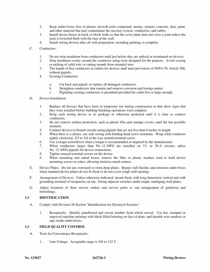
No. 123027 262726-3 Wiring Devices
2. Keep outlet boxes free of plaster, drywall joint compound, mortar, cement, concrete, dust, paint,
and other material that may contaminate the raceway system, conductors, and cables.
3. Install device boxes in brick or block walls so that the cover plate does not cross a joint unless the
joint is troweled flush with the face of the wall.
4. Install wiring devices after all wall preparation, including painting, is complete.
C. Conductors:
1. Do not strip insulation from conductors until just before they are spliced or terminated on devices.
2. Strip insulation evenly around the conductor using tools designed for the purpose. Avoid scoring
or nicking of solid wire or cutting strands from stranded wire.
3. The length of free conductors at outlets for devices shall meet provisions of NFPA 70, Article 300,
without pigtails.
4. Existing Conductors:
a. Cut back and pigtail, or replace all damaged conductors.
b. Straighten conductors that remain and remove corrosion and foreign matter.
c. Pigtailing existing conductors is permitted provided the outlet box is large enough.
D. Device Installation:
1. Replace all devices that have been in temporary use during construction or that show signs that
they were installed before building finishing operations were complete.
2. Keep each wiring device in its package or otherwise protected until it is time to connect
conductors.
3. Do not remove surface protection, such as plastic film and smudge covers, until the last possible
moment.
4. Connect devices to branch circuits using pigtails that are not less than 6 inches in length.
5. When there is a choice, use side wiring with binding-head screw terminals. Wrap solid conductor
tightly clockwise, 2/3 to 3/4 of the way around terminal screw.
6. Use a torque screwdriver when a torque is recommended or required by the manufacturer.
7. When conductors larger than No. 12 AWG are installed on 15- or 20-A circuits, splice
No. 12 AWG pigtails for device connections.
8. Tighten unused terminal screws on the device.
9. When mounting into metal boxes, remove the fiber or plastic washers used to hold device
mounting screws in yokes, allowing metal-to-metal contact.
E. Device Plates: Do not use oversized or extra-deep plates. Repair wall finishes and remount outlet boxes
when standard device plates do not fit flush or do not cover rough wall opening.
F. Arrangement of Devices: Unless otherwise indicated, mount flush, with long dimension vertical and with
grounding terminal of receptacles on top. Group adjacent switches under single, multigang wall plates.
G. Adjust locations of floor service outlets and service poles to suit arrangement of partitions and
furnishings.
3.2 IDENTIFICATION
A. Comply with Division 26 Section "Identification for Electrical Systems."
1. Receptacles: Identify panelboard and circuit number from which served. Use hot, stamped or
engraved machine printing with black-filled lettering on face of plate, and durable wire markers or
tags inside outlet boxes.
3.3 FIELD QUALITY CONTROL
A. Tests for Convenience Receptacles:
1. Line Voltage: Acceptable range is 105 to 132 V.

No. 123027 262726-4 Wiring Devices
2. Percent Voltage Drop under 15-A Load: A value of 6 percent or higher is not acceptable.
3. Ground Impedance: Values of up to 2 ohms are acceptable.
4. GFCI Trip: Test for tripping values specified in UL 1436 and UL 943.
5. Using the test plug, verify that the device and its outlet box are securely mounted.
6. The tests shall be diagnostic, indicating damaged conductors, high resistance at the circuit breaker,
poor connections, inadequate fault current path, defective devices, or similar problems. Correct
circuit conditions, remove malfunctioning units and replace with new ones, and retest as specified
above.
END OF SECTION 262726

No. 123027 262816-1 Enclosed Switches And
Circuit Breakers
SECTION 262816
ENCLOSED SWITCHES AND CIRCUIT BREAKERS
PART 1 - GENERAL
1.1 RELATED DOCUMENTS
A. Drawings and general provisions of the Contract, including General and Supplementary Conditions and
other Division 01 Specification Sections, apply to this Section.
1.2 SUMMARY
A. Section Includes:
1. Fusible switches.
2. Nonfusible switches.
1.3 DEFINITIONS
A. NC: Normally closed.
B. NO: Normally open.
C. SPDT: Single pole, double throw.
1.4 SUBMITTALS
A. Product Data: For each type of enclosed switch, circuit breaker, accessory, and component indicated.
Include dimensioned elevations, sections, weights, and manufacturers' technical data on features,
performance, electrical characteristics, ratings, accessories, and finishes.
1. Enclosure types and details for types other than NEMA 250, Type 1.
2. Current and voltage ratings.
3. Short-circuit current ratings (interrupting and withstand, as appropriate).
4. Detail features, characteristics, ratings, and factory settings of individual overcurrent protective
devices, accessories, and auxiliary components.
5. Include time-current coordination curves (average melt) for each type and rating of overcurrent
protective device; include selectable ranges for each type of overcurrent protective device.
B. Shop Drawings: For enclosed switches and circuit breakers. Include plans, elevations, sections, details,
and attachments to other work.
1. Wiring Diagrams: For power, signal, and control wiring.
C. Operation and Maintenance Data: For enclosed switches and circuit breakers to include in emergency,
operation, and maintenance manuals. In addition to items specified in Division 01 Section "Operation
and Maintenance Data," include the following:
1. Manufacturer's written instructions for testing and adjusting enclosed switches and circuit
breakers.
2. Time-current coordination curves (average melt) for each type and rating of overcurrent protective
device; include selectable ranges for each type of overcurrent protective device.
1.5 QUALITY ASSURANCE
A. Source Limitations: Obtain enclosed switches and circuit breakers, overcurrent protective devices,
components, and accessories, within same product category, from single source from single
manufacturer.

No. 123027 262816-2 Enclosed Switches And
Circuit Breakers
B. Electrical Components, Devices, and Accessories: Listed and labeled as defined in NFPA 70, by a
qualified testing agency, and marked for intended location and application.
C. Comply with NFPA 70 and all local ordinances.
1.6 COORDINATION
A. Coordinate layout and installation of switches, circuit breakers, and components with equipment served
and adjacent surfaces. Maintain required workspace clearances and required clearances for equipment
access doors and panels.
PART 2 - PRODUCTS
2.1 FUSIBLE SWITCHES
A. Manufacturers: Subject to compliance with requirements, provide products by one of the following:
1. Eaton Electrical Inc.; Cutler-Hammer Business Unit.
2. General Electric Company; GE Consumer & Industrial - Electrical Distribution.
3. Siemens Energy & Automation, Inc.
4. Square D; a brand of Schneider Electric.
B. Type HD, Heavy Duty, Single Throw, 600-V ac, 1200 A and Smaller: UL 98 and NEMA KS 1,
horsepower rated, with clips or bolt pads to accommodate specified fuses, lockable handle with capability
to accept three padlocks, and interlocked with cover in closed position.
C. Accessories:
1. Equipment Ground Kit: Internally mounted and labeled for copper and aluminum ground
conductors.
2. Neutral Kit: Internally mounted; insulated, capable of being grounded and bonded; labeled for
copper and aluminum neutral conductors.
2.2 NONFUSIBLE SWITCHES
A. Manufacturers: Subject to compliance with requirements, provide products by one of the following:
1. Eaton Electrical Inc.; Cutler-Hammer Business Unit.
2. General Electric Company; GE Consumer & Industrial - Electrical Distribution.
3. Siemens Energy & Automation, Inc.
4. Square D; a brand of Schneider Electric.
B. Type HD, Heavy Duty, Single Throw, 600-V ac, 1200 A and Smaller: UL 98 and NEMA KS 1,
horsepower rated, lockable handle with capability to accept three padlocks, and interlocked with cover in
closed position.
C. Accessories:
1. Equipment Ground Kit: Internally mounted and labeled for copper and aluminum ground
conductors.
2. Neutral Kit: Internally mounted; insulated, capable of being grounded and bonded; labeled for
copper and aluminum neutral conductors.
2.3 ENCLOSURES
A. Enclosed Switches and Circuit Breakers: NEMA AB 1, NEMA KS 1, NEMA 250, and UL 50, to comply
with environmental conditions at installed location.
1. Indoor, Dry and Clean Locations: NEMA 250, Type 1.
2. Outdoor Locations: NEMA 250, Type 3R.

No. 123027 262816-3 Enclosed Switches And
Circuit Breakers
PART 3 - EXECUTION
3.1 EXAMINATION
A. Examine elements and surfaces to receive enclosed switches and circuit breakers for compliance with
installation tolerances and other conditions affecting performance of the Work.
B. Proceed with installation only after unsatisfactory conditions have been corrected.
3.2 INSTALLATION
A. Install individual wall-mounted switches and circuit breakers with tops at uniform height unless otherwise
indicated.
B. Install fuses in fusible devices.
C. Comply with NECA 1.
3.3 IDENTIFICATION
A. Comply with requirements in Division 26 Section "Identification for Electrical Systems."
1. Identify field-installed conductors, interconnecting wiring, and components; provide warning
signs.
2. Label each enclosure with engraved metal or laminated-plastic nameplate.
3.4 FIELD QUALITY CONTROL
A. Acceptance Testing Preparation:
1. Test insulation resistance for each enclosed switch and circuit breaker, component, connecting
supply, feeder, and control circuit.
2. Test continuity of each circuit.
B. Tests and Inspections:
1. Perform each visual and mechanical inspection and electrical test stated in NETA Acceptance
Testing Specification. Certify compliance with test parameters.
2. Correct malfunctioning units on-site, where possible, and retest to demonstrate compliance;
otherwise, replace with new units and retest.
C. Enclosed switches and circuit breakers will be considered defective if they do not pass tests and
inspections.
3.5 ADJUSTING
A. Adjust moving parts and operable components to function smoothly, and lubricate as recommended by
manufacturer.
END OF SECTION 262816

No. 123027 31 10 00 - 1 SITE CLEARING
SECTION 31 10 00
PART 1 - GENERAL
SITE CLEARING
1.1 RELATED DOCUMENTS
A. Drawings and general provisions of the Contract, including General and Supplementary Conditions and Division 01 Specification Sections, apply to this Section.
1.2 SUMMARY
A. Section Includes:
1. Protecting existing vegetation to remain. 2. Removing existing vegetation. 3. Clearing and grubbing. 4. Stripping and stockpiling topsoil. 5. Removing above- and below-grade site improvements. 6. Disconnecting, capping or sealing, removing site utilities abandoning site utilities in
place. 7. Temporary erosion- and sedimentation-control measures.
B. Related Sections:
1. Division 01 Section "Temporary Facilities and Controls" for temporary utility services, construction and support facilities, security and protection facilities, and temporary erosion and sedimentation-control measures.
2. Division 01 Section "Execution" for field engineering and surveying. 3. Division 01 Section "Construction Waste Management and Disposal for additional LEED
requirements.
1.3 DEFINITIONS
A. Subsoil: All soil beneath the topsoil layer of the soil profile, and typified by the lack of organic matter and soil organisms.
B. Surface Soil: Soil that is present at the top layer of the existing soil profile at the Project site. In undisturbed areas, the surface soil is typically topsoil; but in disturbed areas such as urban environments, the surface soil can be subsoil.
C. Topsoil: Top layer of the soil profile consisting of existing native surface topsoil or existing in-place surface soil and is the zone where plant roots grow. Its appearance is generally friable, pervious, and black or a darker shade of brown, gray, or red than underlying subsoil; reasonably free of subsoil, clay lumps, gravel, and other objects more than 2 inches (50 mm) in diameter; and free of subsoil and weeds, roots, toxic materials, or other nonsoil materials.

No. 123027 31 10 00 - 2 SITE CLEARING
D. Plant-Protection Zone: Area surrounding individual trees, groups of trees, shrubs, or other vegetation to be protected during construction, and indicated on Drawings.
E. Tree-Protection Zone: Area surrounding individual trees or groups of trees to be protected during construction, and indicated on Drawings.
F. Vegetation: Trees, shrubs, groundcovers, grass, and other plants.
1.4 MATERIAL OWNERSHIP
A. Except for stripped topsoil and other materials indicated to be stockpiled or otherwise remain Owner's property, cleared materials shall become Contractor's property and shall be removed from Project site.
1.5 SUBMITTALS
A. Existing Conditions: Documentation of existing trees and plantings, adjoining construction, and site improvements that establishes preconstruction conditions that might be misconstrued as damage caused by site clearing.
1. Use sufficiently detailed photographs or videotape. 2. Include plans and notations to indicate specific wounds and damage conditions of each
tree or other plants designated to remain.
B. Record Drawings: Identifying and accurately showing locations of capped utilities and other subsurface structural, electrical, and mechanical conditions.
1.6 PROJECT CONDITIONS
A. Traffic: Minimize interference with adjoining roads, streets, walks, and other adjacent occupied or used facilities during site-clearing operations.
1. Do not close or obstruct streets, walks, or other adjacent occupied or used facilities without permission from Owner and authorities having jurisdiction.
2. Provide alternate routes around closed or obstructed traffic ways if required by Owner or authorities having jurisdiction.
B. Improvements on Adjoining Property: Authority for performing site clearing indicated on property adjoining Owner's property will be obtained by Owner before award of Contract.
1. Do not proceed with work on adjoining property until directed by Architect.
C. Utility Locator Service: Notify “Julie” for area where Project is located before site clearing.
D. Do not commence site clearing operations until temporary erosion- and sedimentation-control and plant-protection measures are in place.
E. The following practices are prohibited within protection zones:

No. 123027 31 10 00 - 3 SITE CLEARING
1. Storage of construction materials, debris, or excavated material. 2. Parking vehicles or equipment. 3. Foot traffic. 4. Erection of sheds or structures. 5. Impoundment of water. 6. Excavation or other digging unless otherwise indicated. 7. Attachment of signs to or wrapping materials around trees or plants unless otherwise
indicated.
F. Do not direct vehicle or equipment exhaust towards protection zones.
G. Prohibit heat sources, flames, ignition sources, and smoking within or near protection zones.
H. Soil Stripping, Handling, and Stockpiling: Perform only when the topsoil is dry or slightly moist.
PART 2 - PRODUCTS
2.1 MATERIALS
A. Satisfactory Soil Material: Requirements for satisfactory soil material are specified in Division 31 Section "Earth Moving."
1. Obtain approved borrow soil material off-site when satisfactory soil material is not available on-site.
PART 3 - EXECUTION
3.1 PREPARATION
A. Protect and maintain benchmarks and survey control points from disturbance during construction.
B. Locate and clearly identify trees, shrubs, and other vegetation to remain. Flag each tree trunk at 54 inches (1372 mm)
C. Protect existing site improvements to remain from damage during construction.
above the ground.
1. Restore damaged improvements to their original condition, as acceptable to Owner.
3.2 TEMPORARY EROSION AND SEDIMENTATION CONTROL
A. Provide temporary erosion- and sedimentation-control measures to prevent soil erosion and discharge of soil-bearing water runoff or airborne dust to adjacent properties and walkways, according to erosion- and sedimentation-control Drawings and requirements of authorities having jurisdiction.

No. 123027 31 10 00 - 4 SITE CLEARING
B. Verify that flows of water redirected from construction areas or generated by construction activity do not enter or cross protection zones.
C. Inspect, maintain, and repair erosion- and sedimentation-control measures during construction until permanent vegetation has been established.
D. Remove erosion and sedimentation controls and restore and stabilize areas disturbed during removal.
3.3 TREE AND PLANT PROTECTION
A. General: Protect trees and plants remaining on-site according to requirements in Division 01 Section "Temporary Tree and Plant Protection."
B. Repair or replace trees, shrubs, and other vegetation indicated to remain or be relocated that are damaged by construction operations, in a manner approved by Architect.
3.4 EXISTING UTILITIES
A. Owner will arrange for disconnecting and sealing indicated utilities that serve existing structures before site clearing, when requested by Contractor.
1. Verify that utilities have been disconnected and capped before proceeding with site clearing.
B. Locate, identify, disconnect, and seal or cap utilities indicated to be removed or abandoned in place.
1. Arrange with utility companies to shut off indicated utilities. 2. Owner will arrange to shut off indicated utilities when requested by Contractor.
C. Locate, identify, and disconnect utilities indicated to be abandoned in place.
D. Interrupting Existing Utilities: Do not interrupt utilities serving facilities occupied by Owner or others unless permitted under the following conditions and then only after arranging to provide temporary utility services according to requirements indicated:
1. Notify Architect not less than two (2) days in advance of proposed utility interruptions. 2. Do not proceed with utility interruptions without Architect's written permission.
E. Excavate for and remove underground utilities indicated to be removed.
3.5 CLEARING AND GRUBBING
A. Remove obstructions, trees, shrubs, and other vegetation to permit installation of new construction.
1. Do not remove trees, shrubs, and other vegetation indicated to remain or to be relocated.

No. 123027 31 10 00 - 5 SITE CLEARING
2. Grind down stumps and remove roots, obstructions, and debris to a depth of 18 inches (450 mm)
3. Use only hand methods for grubbing within protection zones. below exposed subgrade.
4. Chip removed tree branches and stockpile in areas approved by Architect or dispose of off-site.
B. Fill depressions caused by clearing and grubbing operations with satisfactory soil material unless further excavation or earthwork is indicated.
1. Place fill material in horizontal layers not exceeding a loose depth of 8 inches (200 mm)
3.6 TOPSOIL STRIPPING
, and compact each layer to a density equal to adjacent original ground.
A. Remove sod and grass before stripping topsoil.
B. Strip in a manner to prevent intermingling with underlying subsoil or other waste materials.
1. Remove subsoil and nonsoil materials from topsoil, including clay lumps, gravel, and other objects more than 2 inches (50 mm)
C. Stockpile topsoil away from edge of excavations without intermixing with subsoil. Grade and shape stockpiles to drain surface water. Cover to prevent windblown dust and erosion by water.
in diameter; trash, debris, weeds, roots, and other waste materials.
1. Limit height of topsoil stockpiles to 72 inches (1800 mm)2. Do not stockpile topsoil within protection zones.
.
3. Dispose of surplus topsoil. Surplus topsoil is that which exceeds quantity indicated to be stockpiled or reused.
4. Stockpile surplus topsoil to allow for respreading deeper topsoil.
3.7 SITE IMPROVEMENTS
A. Remove existing above- and below-grade improvements as indicated and necessary to facilitate new construction.
B. Remove slabs, paving, curbs, gutters, and aggregate base as indicated.
1. Unless existing full-depth joints coincide with line of demolition, neatly saw-cut along line of existing pavement to remain before removing adjacent existing pavement. Saw-cut faces vertically.
2. Paint cut ends of steel reinforcement in concrete to remain with two coats of antirust coating, following coating manufacturer's written instructions. Keep paint off surfaces that will remain exposed.
3.8 DISPOSAL OF SURPLUS AND WASTE MATERIALS
A. Remove surplus soil material, unsuitable topsoil, obstructions, demolished materials, and waste materials including trash and debris, and legally dispose of them off Owner's property.

No. 123027 31 10 00 - 6 SITE CLEARING
B. Separate recyclable materials produced during site clearing from other non-recyclable materials. Store or stockpile without intermixing with other materials and transport them to recycling facilities. Do not interfere with other Project work.
END OF SECTION 31 10 00
No. 123027 31 20 00 - 1 EARTH MOVING
SECTION 31 20 00
PART 1 - GENERAL
EARTH MOVING
1.1 RELATED DOCUMENTS
A. Drawings and general provisions of the Contract, including General and Supplementary Conditions and Division 01 Specification Sections, apply to this Section.
1.2 SUMMARY
A. Section Includes:
1. Preparing subgrades for slabs-on-grade walks pavements, and turf and grasses 2. Excavating and backfilling for buildings and structures. 3. Drainage course for concrete slabs-on-grade. 4. Subbase course for concrete walks pavements. 5. Subbase course and base course for asphalt paving. 6. Subsurface drainage backfill for walls and trenches. 7. Excavating and backfilling trenches for utilities and pits for buried utility structures. 8. Excavating well hole to accommodate elevator-cylinder assembly.
B. Related Sections:
1. Division 01 Section "Construction Progress Documentation” for recording pre-excavation and earth moving progress.
2. Division 01 Section "Temporary Facilities and Controls" for temporary controls, utilities, and support facilities; also for temporary site fencing if not in another Section.
3. Division 03 Section "Cast-in-Place Concrete" for granular course if placed over vapor retarder and beneath the slab-on-grade.
4. Division 31 Section "Site Clearing" for site stripping, grubbing, stripping and stockpiling topsoil, and removal of above- and below-grade improvements and utilities.
5. Division 31 Section "Dewatering" for lowering and disposing of ground water during construction.
6. Division 31 Section "Excavation Support and Protection" for shoring, bracing, and sheet piling of excavations.
7. Division 31 Section "Drilled Concrete Piers and Shafts" for excavation of shafts and disposal of surplus excavated material.
8. Division 32 Section "Turf and Grasses" for finish grading in turf and grass areas, including preparing and placing planting soil for turf areas.
9. Division 32 Section "Plants" for finish grading in planting areas and tree and shrub pit excavation and planting.
10. Division 33 Section "Subdrainage" for drainage of foundations, slabs-on-grade, walls, and landscaped areas.

No. 123027 31 20 00 - 2 EARTH MOVING
1.3 UNIT PRICES
A. Work of this Section is affected by unit prices for earth moving specified in Division 01 Section "Unit Prices."
B. Quantity allowances for earth moving are included in Division 01 Section "Allowances."
1.4 DEFINITIONS
A. Backfill: Soil material or controlled low-strength material used to fill an excavation.
1. Initial Backfill: Backfill placed beside and over pipe in a trench, including haunches to support sides of pipe.
2. Final Backfill: Backfill placed over initial backfill to fill a trench.
B. Base Course: Aggregate layer placed between the subbase course and hot-mix asphalt paving.
C. Bedding Course: Aggregate layer placed over the excavated subgrade in a trench before laying pipe.
D. Borrow Soil: Satisfactory soil imported from off-site for use as fill or backfill.
E. Drainage Course: Aggregate layer supporting the slab-on-grade that also minimizes upward capillary flow of pore water.
F. Excavation: Removal of material encountered above subgrade elevations and to lines and dimensions indicated.
1. Authorized Additional Excavation: Excavation below subgrade elevations or beyond indicated lines and dimensions as directed by Architect. Authorized additional excavation and replacement material will be paid for according to Contract provisions for unit prices.
2. Bulk Excavation: Excavation more than 10 feet in width and more than 30 feet3. Unauthorized Excavation: Excavation below subgrade elevations or beyond indicated
lines and dimensions without direction by Architect. Unauthorized excavation, as well as remedial work directed by Architect, shall be without additional compensation.
in length.
G. Fill: Soil materials used to raise existing grades.
H. Structures: Buildings, footings, foundations, retaining walls, slabs, tanks, curbs, mechanical and electrical appurtenances, or other man-made stationary features constructed above or below the ground surface.
I. Subbase Course: Aggregate layer placed between the subgrade and base course for hot-mix asphalt pavement, or aggregate layer placed between the subgrade and a cement concrete pavement or a cement concrete or hot-mix asphalt walk.
J. Subgrade: Uppermost surface of an excavation or the top surface of a fill or backfill immediately below subbase, drainage fill, drainage course, or topsoil materials.

No. 123027 31 20 00 - 3 EARTH MOVING
K. Utilities: On-site underground pipes, conduits, ducts, and cables, as well as underground services within buildings.
1.5 SUBMITTALS
A. Product Data: For each type of the following manufactured products required:
1. Geotextiles. 2. Warning tapes.
B. Samples for Verification: For the following products, in sizes indicated below:
1. Geotextile: 12 by 12 inches
1.6 PROJECT CONDITIONS
.
A. Traffic: Minimize interference with adjoining roads, streets, walks, and other adjacent occupied or used facilities during earth moving operations.
1. Do not close or obstruct streets, walks, or other adjacent occupied or used facilities without permission from Owner and authorities having jurisdiction.
2. Provide alternate routes around closed or obstructed traffic ways if required by Owner or authorities having jurisdiction.
B. Utility Locator Service: Notify “Julie” for area where Project is located before beginning earth moving operations.
PART 2 - PRODUCTS
2.1 SOIL MATERIALS
A. General: Provide borrow soil materials when sufficient satisfactory soil materials are not available from excavations.
B. Satisfactory Soils: Soil Classification Groups GW, GP, GM, SW, SP, and SM according to ASTM D 2487 Groups A-1, A-2-4, A-2-5, and A-3 according to AASHTO M 145, or a combination of these groups; free of rock or gravel larger than 3 inches
1. Liquid Limit: Per IDOT Specifications.
in any dimension, debris, waste, frozen materials, vegetation, and other deleterious matter.
2. Plasticity Index: Per IDOT Specifications.
C. Unsatisfactory Soils: Soil Classification Groups GC, SC, CL, ML, OL, CH, MH, OH, and PT according to ASTM D 2487 Groups A-2-6, A-2-7, A-4, A-5, A-6, and A-7 according to AASHTO M 145, or a combination of these groups.
1. Unsatisfactory soils also include satisfactory soils not maintained within 2 percent of optimum moisture content at time of compaction.

No. 123027 31 20 00 - 4 EARTH MOVING
D. Subbase Material: Naturally or artificially graded mixture of natural or crushed gravel, crushed stone, and natural or crushed sand; ASTM D 2940; with at least 90 percent passing a 1-1/2-inch (37.5-mm) sieve and not more than 12 percent passing a No. 200 (0.075-mm)
E. Base Course: Naturally or artificially graded mixture of natural or crushed gravel, crushed stone, and natural or crushed sand; ASTM D 2940; with at least 95 percent passing a
sieve.
1-1/2-inch (37.5-mm) sieve and not more than 8 percent passing a No. 200 (0.075-mm)
F. Engineered Fill: Naturally or artificially graded mixture of natural or crushed gravel, crushed stone, and natural or crushed sand; ASTM D 2940; with at least 90 percent passing a
sieve.
1-1/2-inch (37.5-mm) sieve and not more than 12 percent passing a No. 200 (0.075-mm)
G. Bedding Course: Naturally or artificially graded mixture of natural or crushed gravel, crushed stone, and natural or crushed sand; ASTM D 2940; except with 100 percent passing a
sieve.
1-inch (25-mm) sieve and not more than 8 percent passing a No. 200 (0.075-mm)
H. Drainage Course: Narrowly graded mixture of crushed stone, or crushed or uncrushed gravel; ASTM D 448; coarse-aggregate grading Size 57; with 100 percent passing a
sieve.
1-1/2-inch (37.5-mm) sieve and 0 to 5 percent passing a No. 8 (2.36-mm)
I. Filter Material: Narrowly graded mixture of natural or crushed gravel, or crushed stone and natural sand; ASTM D 448; coarse-aggregate grading Size 67; with 100 percent passing a
sieve.
1-inch (25-mm) sieve and 0 to 5 percent passing a No. 4 (4.75-mm)
J. Sand: ASTM C 33; fine aggregate.
sieve.
K. Impervious Fill: Clayey gravel and sand mixture capable of compacting to a dense state.
2.2 GEOTEXTILES
A. Subsurface Drainage Geotextile: Nonwoven needle-punched geotextile, manufactured for subsurface drainage applications, made from polyolefins or polyesters; with elongation greater than 50 percent; complying with AASHTO M 288 and the following, measured per test methods referenced:
1. Survivability: Class 2; AASHTO M 288. 2. Grab Tensile Strength: 157 lbf3. Sewn Seam Strength:
; ASTM D 4632. 142 lbf
4. Tear Strength: ; ASTM D 4632.
56 lbf5. Puncture Strength:
; ASTM D 4533. 56 lbf
6. Apparent Opening Size: ; ASTM D 4833. No. 60
7. Permittivity: 0.2 per second, minimum; ASTM D 4491. sieve, maximum; ASTM D 4751.
8. UV Stability: 50 percent after 500 hours' exposure; ASTM D 4355.
B. Separation Geotextile: Woven geotextile fabric, manufactured for separation applications, made from polyolefins or polyesters; with elongation less than 50 percent; complying with AASHTO M 288 and the following, measured per test methods referenced:
1. Survivability: Class 2; AASHTO M 288. 2. Grab Tensile Strength: 247 lbf; ASTM D 4632.

No. 123027 31 20 00 - 5 EARTH MOVING
3. Sewn Seam Strength: 222 lbf4. Tear Strength:
; ASTM D 4632. 90 lbf
5. Puncture Strength: ; ASTM D 4533.
90 lbf6. Apparent Opening Size:
; ASTM D 4833. No. 60
7. Permittivity: 0.02 per second, minimum; ASTM D 4491. sieve, maximum; ASTM D 4751.
8. UV Stability: 50 percent after 500 hours' exposure; ASTM D 4355.
2.3 ACCESSORIES
A. Warning Tape: Acid- and alkali-resistant, polyethylene film warning tape manufactured for marking and identifying underground utilities, 6 inches wide and 4 mils
1. Red: Electric.
thick, continuously inscribed with a description of the utility; colored as follows:
2. Yellow: Gas, oil, steam, and dangerous materials. 3. Orange: Telephone and other communications. 4. Blue: Water systems. 5. Green: Sewer systems.
B. Detectable Warning Tape: Acid- and alkali-resistant, polyethylene film warning tape manufactured for marking and identifying underground utilities, a minimum of 6 inches (150 wide and 4 mils thick, continuously inscribed with a description of the utility, with metallic core encased in a protective jacket for corrosion protection, detectable by metal detector when tape is buried up to 30 inches
1. Red: Electric.
deep; colored as follows:
2. Yellow: Gas, oil, steam, and dangerous materials. 3. Orange: Telephone and other communications. 4. Blue: Water systems. 5. Green: Sewer systems.
PART 3 - EXECUTION
3.1 PREPARATION
A. Protect structures, utilities, sidewalks, pavements, and other facilities from damage caused by settlement, lateral movement, undermining, washout, and other hazards created by earth moving operations.
B. Protect and maintain erosion and sedimentation controls during earth moving operations.
C. Protect subgrades and foundation soils from freezing temperatures and frost. Remove temporary protection before placing subsequent materials.
3.2 DEWATERING
A. Prevent surface water and ground water from entering excavations, from ponding on prepared subgrades, and from flooding Project site and surrounding area.
No. 123027 31 20 00 - 6 EARTH MOVING
B. Protect subgrades from softening, undermining, washout, and damage by rain or water accumulation.
1. Reroute surface water runoff away from excavated areas. Do not allow water to accumulate in excavations. Do not use excavated trenches as temporary drainage ditches.
3.3 EXPLOSIVES
A. Explosives: Do not use explosives.
3.4 EXCAVATION, GENERAL
A. Unclassified Excavation: Excavate to subgrade elevations regardless of the character of surface and subsurface conditions encountered. Unclassified excavated materials may include rock, soil materials, and obstructions. No changes in the Contract Sum or the Contract Time will be authorized for rock excavation or removal of obstructions.
1. If excavated materials intended for fill and backfill include unsatisfactory soil materials and rock, replace with satisfactory soil materials.
2. Remove rock to lines and grades indicated to permit installation of permanent construction without exceeding the following dimensions: a. 12 inches
3.5 EXCAVATION FOR WALKS AND PAVEMENTS
outside of concrete forms at footings.
A. Excavate surfaces under walks and pavements to indicated lines, cross sections, elevations, and subgrades.
3.6 EXCAVATION FOR UTILITY TRENCHES
A. Excavate trenches to indicated gradients, lines, depths, and elevations.
1. Beyond building perimeter, excavate trenches to allow installation of top of pipe below frost line.
B. Excavate trenches to uniform widths to provide the following clearance on each side of pipe or conduit. Excavate trench walls vertically from trench bottom to 12 inches (300 mm)
1. Clearance:
higher than top of pipe or conduit unless otherwise indicated.
12 inches (300 mm)
C. Trench Bottoms: Excavate and shape trench bottoms to provide uniform bearing and support of pipes and conduit. Shape subgrade to provide continuous support for bells, joints, and barrels of pipes and for joints, fittings, and bodies of conduits. Remove projecting stones and sharp objects along trench subgrade.
each side of pipe or conduit.

No. 123027 31 20 00 - 7 EARTH MOVING
1. For pipes and conduit less than 6 inches
2. For pipes and conduit
in nominal diameter, hand-excavate trench bottoms and support pipe and conduit on an undisturbed subgrade.
6 inches
3. For flat-bottomed, multiple-duct conduit units, hand-excavate trench bottoms and support conduit on an undisturbed subgrade.
or larger in nominal diameter, shape bottom of trench to support bottom 90 degrees of pipe or conduit circumference. Fill depressions with tamped sand backfill.
4. Excavate trenches 6 inches
D. Trench Bottoms: Excavate trenches
deeper than elevation required in rock or other unyielding bearing material to allow for bedding course.
4 inches
1. Excavate trenches
deeper than bottom of pipe and conduit elevations to allow for bedding course. Hand-excavate deeper for bells of pipe.
6 inches (150 mm)
E. Trenches in Tree- and Plant-Protection Zones:
deeper than elevation required in rock or other unyielding bearing material to allow for bedding course.
1. Hand-excavate to indicated lines, cross sections, elevations, and subgrades. Use narrow-tine spading forks to comb soil and expose roots. Do not break, tear, or chop exposed roots. Do not use mechanical equipment that rips, tears, or pulls roots.
2. Do not cut main lateral roots or taproots; cut only smaller roots that interfere with installation of utilities.
3. Cut and protect roots according to requirements in Division 01 Section "Temporary Tree and Plant Protection."
3.7 SUBGRADE INSPECTION
A. Notify Architect when excavations have reached required subgrade.
B. If Architect determines that unsatisfactory soil is present, continue excavation and replace with compacted backfill or fill material as directed.
C. Proof-roll subgrade below the building slabs and pavements with a pneumatic-tired equipment to identify soft pockets and areas of excess yielding. Do not proof-roll wet or saturated subgrades.
1. Completely proof-roll subgrade in one direction, repeating proof-rolling in direction perpendicular to first direction. Limit vehicle speed to 1 mph
2. Excavate soft spots, unsatisfactory soils, and areas of excessive pumping or rutting, as determined by Architect, and replace with compacted backfill or fill as directed.
.
D. Authorized additional excavation and replacement material will be paid for according to Contract provisions for unit prices.
E. Reconstruct subgrades damaged by freezing temperatures, frost, rain, accumulated water, or construction activities, as directed by Architect, without additional compensation.

No. 123027 31 20 00 - 8 EARTH MOVING
3.8 UNAUTHORIZED EXCAVATION
A. Fill unauthorized excavation under foundations or wall footings by extending bottom elevation of concrete foundation or footing to excavation bottom, without altering top elevation. Lean concrete fill, with 28-day compressive strength of 2500 psi
1. Fill unauthorized excavations under other construction, pipe, or conduit as directed by Architect.
, may be used when approved by Architect.
3.9 STORAGE OF SOIL MATERIALS
A. Stockpile borrow soil materials and excavated satisfactory soil materials without intermixing. Place, grade, and shape stockpiles to drain surface water. Cover to prevent windblown dust.
1. Stockpile soil materials away from edge of excavations. Do not store within drip line of remaining trees.
3.10 BACKFILL
A. Place and compact backfill in excavations promptly, but not before completing the following:
1. Construction below finish grade including, where applicable, subdrainage, dampproofing, waterproofing, and perimeter insulation.
2. Surveying locations of underground utilities for Record Documents. 3. Testing and inspecting underground utilities. 4. Removing concrete formwork. 5. Removing trash and debris. 6. Removing temporary shoring and bracing, and sheeting. 7. Installing permanent or temporary horizontal bracing on horizontally supported walls.
B. Place backfill on subgrades free of mud, frost, snow, or ice.
3.11 UTILITY TRENCH BACKFILL
A. Place backfill on subgrades free of mud, frost, snow, or ice.
B. Place and compact bedding course on trench bottoms and where indicated. Shape bedding course to provide continuous support for bells, joints, and barrels of pipes and for joints, fittings, and bodies of conduits.
C. Trenches under Footings: Backfill trenches excavated under footings and within 18 inches (450 mm)
D. Trenches under Roadways: Provide
of bottom of footings with satisfactory soil; fill with concrete to elevation of bottom of footings. Concrete is specified in Division 03 Section "Cast-in-Place Concrete Miscellaneous Cast-in-Place Concrete."
4-inch- thick, concrete-base slab support for piping or conduit less than 30 inches below surface of roadways. After installing and testing, completely encase piping or conduit in a minimum of 4 inches of concrete before backfilling or placing
No. 123027 31 20 00 - 9 EARTH MOVING
roadway subbase course. Concrete is specified in Division 03 Section "Cast-in-Place Concrete Miscellaneous Cast-in-Place Concrete."
E. Backfill voids with satisfactory soil while removing shoring and bracing.
F. Place and compact initial backfill of subbase material, free of particles larger than 1 inch in any dimension, to a height of 12 inches
1. Carefully compact initial backfill under pipe haunches and compact evenly up on both sides and along the full length of piping or conduit to avoid damage or displacement of piping or conduit. Coordinate backfilling with utilities testing.
over the pipe or conduit.
G. Place and compact final backfill of satisfactory soil to final subgrade elevation.
H. Install warning tape directly above utilities, 12 inches below finished grade, except 6 inches
3.12 SOIL FILL
below subgrade under pavements and slabs.
A. Plow, scarify, bench, or break up sloped surfaces steeper than 1 vertical to 4 horizontal so fill material will bond with existing material.
B. Place and compact fill material in layers to required elevations as follows:
1. Under grass and planted areas, use satisfactory soil material. 2. Under walks and pavements, use satisfactory soil material. 3. Under steps and ramps, use engineered fill. 4. Under building slabs, use engineered fill. 5. Under footings and foundations, use engineered fill.
C. Place soil fill on subgrades free of mud, frost, snow, or ice.
3.13 SOIL MOISTURE CONTROL
A. Uniformly moisten or aerate subgrade and each subsequent fill or backfill soil layer before compaction to within 2 percent of optimum moisture content.
1. Do not place backfill or fill soil material on surfaces that are muddy, frozen, or contain frost or ice.
2. Remove and replace, or scarify and air dry, otherwise satisfactory soil material that exceeds optimum moisture content by 2 percent and is too wet to compact to specified dry unit weight.
3.14 COMPACTION OF SOIL BACKFILLS AND FILLS
A. Place backfill and fill soil materials in layers not more than 8 inches in loose depth for material compacted by heavy compaction equipment, and not more than 4 inches in loose depth for material compacted by hand-operated tampers.

No. 123027 31 20 00 - 10 EARTH MOVING
B. Place backfill and fill soil materials evenly on all sides of structures to required elevations, and uniformly along the full length of each structure.
C. Compact soil materials to not less than the following percentages of maximum dry unit weight according to ASTM D 698:
1. Under structures, building slabs, steps, and pavements, scarify and recompact top 12 inches
2. Under walkways, scarify and recompact top of existing subgrade and each layer of backfill or fill soil material at 95 percent.
6 inches
3. Under turf or unpaved areas, scarify and recompact top
below subgrade and compact each layer of backfill or fill soil material at 92 percent.
6 inches
4. For utility trenches, compact each layer of initial and final backfill soil material at 85 percent.
below subgrade and compact each layer of backfill or fill soil material at 85 percent.
3.15 GRADING
A. General: Uniformly grade areas to a smooth surface, free of irregular surface changes. Comply with compaction requirements and grade to cross sections, lines, and elevations indicated.
1. Provide a smooth transition between adjacent existing grades and new grades. 2. Cut out soft spots, fill low spots, and trim high spots to comply with required surface
tolerances.
B. Site Rough Grading: Slope grades to direct water away from buildings and to prevent ponding. Finish subgrades to required elevations within the following tolerances:
1. Turf or Unpaved Areas: Plus or minus 1 inch2. Walks: Plus or minus
. 1 inch
3. Pavements: Plus or minus .
1/2 inch
C. Grading inside Building Lines: Finish subgrade to a tolerance of
1/2 inch when tested with a 10-foot
3.16 SUBSURFACE DRAINAGE
straightedge.
A. Subdrainage Pipe: Specified in Division 33 Section "Subdrainage."
B. Subsurface Drain: Place subsurface drainage geotextile around perimeter of subdrainage trench. Place a 6-inch course of filter material on subsurface drainage geotextile to support subdrainage pipe. Encase subdrainage pipe in a minimum of 12 inches of filter material, placed in compacted layers 6 inches thick, and wrap in subsurface drainage geotextile, overlapping sides and ends at least 6 inches
1. Compact each filter material layer to 85 percent of maximum dry unit weight according to ASTM D 698.

No. 123027 31 20 00 - 11 EARTH MOVING
C. Drainage Backfill: Place and compact filter material over subsurface drain, in width indicated, to within 12 inches of final subgrade, in compacted layers 6 inches thick. Overlay drainage backfill with one layer of subsurface drainage geotextile, overlapping sides and ends at least 6 inches
1. Compact each filter material layer to 85 percent of maximum dry unit weight according to ASTM D 698.
2. Place and compact impervious fill over drainage backfill in 6-inch-
3.17 SUBBASE AND BASE COURSES UNDER PAVEMENTS AND WALKS
thick compacted layers to final subgrade.
A. Place subbase course and base course on subgrades free of mud, frost, snow, or ice.
B. On prepared subgrade, place subbase course and base course under pavements and walks as follows:
1. Install separation geotextile on prepared subgrade according to manufacturer's written instructions, overlapping sides and ends.
2. Place base course material over subbase course under hot-mix asphalt pavement. 3. Shape subbase course and base course to required crown elevations and cross-slope
grades. 4. Place subbase course and base course 6 inches
5. Place subbase course and base course that exceeds
or less in compacted thickness in a single layer.
6 inches (150 mm) in compacted thickness in layers of equal thickness, with no compacted layer more than 6 inches or less than 3 inches
6. Compact subbase course and base course at optimum moisture content to required grades, lines, cross sections, and thickness to not less than 95 percent of maximum dry unit weight according to ASTM D 698.
thick.
C. Pavement Shoulders: Place shoulders along edges of subbase course and base course to prevent lateral movement. Construct shoulders, at least 12 inches
3.18 DRAINAGE COURSE UNDER CONCRETE SLABS-ON-GRADE
wide, of satisfactory soil materials and compact simultaneously with each subbase and base layer to not less than 95 percent of maximum dry unit weight according to ASTM D 698.
A. Place drainage course on subgrades free of mud, frost, snow, or ice.
B. On prepared subgrade, place and compact drainage course under cast-in-place concrete slabs-on-grade as follows:
1. Install subdrainage geotextile on prepared subgrade according to manufacturer's written instructions, overlapping sides and ends.
2. Place drainage course 6 inches3. Place drainage course that exceeds
or less in compacted thickness in a single layer. 6 inches in compacted thickness in layers of equal
thickness, with no compacted layer more than 6 inches thick or less than 3 inches thick.

No. 123027 31 20 00 - 12 EARTH MOVING
4. Compact each layer of drainage course to required cross sections and thicknesses to not less than 95 percent of maximum dry unit weight according to ASTM D 698.
3.19 FIELD QUALITY CONTROL
A. Testing Agency: Owner will engage a qualified geotechnical engineering testing agency to perform tests and inspections.
B. Allow testing agency to inspect and test subgrades and each fill or backfill layer. Proceed with subsequent earth moving only after test results for previously completed work comply with requirements.
C. Footing Subgrade: At footing subgrades, at least one test of each soil stratum will be performed to verify design bearing capacities. Subsequent verification and approval of other footing subgrades may be based on a visual comparison of subgrade with tested subgrade when approved by Architect.
D. When testing agency reports that subgrades, fills, or backfills have not achieved degree of compaction specified, scarify and moisten or aerate, or remove and replace soil materials to depth required; recompact and retest until specified compaction is obtained.
3.20 PROTECTION
A. Protecting Graded Areas: Protect newly graded areas from traffic, freezing, and erosion. Keep free of trash and debris.
B. Repair and reestablish grades to specify tolerances where completed or partially completed surfaces become eroded, rutted, settled, or where they lose compaction due to subsequent construction operations or weather conditions.
1. Scarify or remove and replace soil material to depth as directed by Architect; reshape and recompact.
C. Where settling occurs before Project correction period elapses, remove finished surfacing, backfill with additional soil material, compact, and reconstruct surfacing.
1. Restore appearance, quality, and condition of finished surfacing to match adjacent work, and eliminate evidence of restoration to greatest extent possible.
3.21 DISPOSAL OF SURPLUS AND WASTE MATERIALS
A. Transport surplus satisfactory soil to designated storage areas on Owner's property. Stockpile or spread soil as directed by Architect.
1. Remove waste materials, including unsatisfactory soil, trash, and debris, and legally dispose of them off Owner's property.
END OF SECTION 31 20 00

No. 123027 31 22 13 - 1 ROUGH GRADING
SECTION 31 22 13
ROUGH GRADING
PART 1 - GENERAL
1.1 Work Included
A. Drawings and General Provisions of the Contract, including General and Supplementary Conditions and Division I Specifications Sections apply to this entire section.
B. The work of this section shall consist of layout, excavation, backfilling, disposal of excess
materials, compaction and grading. 1.2 Related Work Specified Elsewhere
A. Section 312219 - Finish Grading B. Section 321216 – Asphalt Paving C. Section 321813 - Synthetic Turf System D. Section 321815 - Under-drainage System
1.3 Quality Assurance
A. Installers’ Qualifications: Firm with at least 3 years of successful installation experience on
projects with work similar to that required for this project. B. Submittals 1. Record Drawings: At project close-out, submit record drawings of installed work.
Especially note located utilities, areas of over-excavation, removal of unsuitable soils, and backfill.
1.4 Project Conditions
A. Verify all existing utility locations prior to beginning earthwork operations.
B. Protect existing features designated to remain as part of the final landscape work. C. Promptly repair damage to adjacent facilities caused by earthwork operations. Cost of
repairs at Contractor’s expense. D. Promptly notify Architect and Construction Manager of unexpected sub-surface
conditions. 1.5 Quality Assurance
A. Codes and Standards: Perform earthwork and site grading in compliance with applicable requirements of governing authorities having jurisdiction.

No. 123027 31 22 13 - 2 ROUGH GRADING
1.6 Protection
A. Protect trees, shrubs, lawns, and other features remaining.
B. Protect bench marks and existing structures.
C. Protect above or below grade utilities which are to remain.
D. Protect existing pavement and curbs
E. Repair damage.
1.7 Tests A. The Owner will employ a qualified testing laboratory to furnish all of the soil engineering
and testing services. 1.8 References A. ANSI/ASTM D1557 - Moisture-Density Relations of Soils and Soil-Aggregate Mixture.
PART 2 - PRODUCTS
2.1 Fill Materials
A. Engineered fill shall consist of a granular material meeting IDOT specifications. B. When necessary, compact subsoil surfaces to density requirements for backfill material. C. Moisten fill material to optimum moisture content prior to compaction. D. Do not place backfill of fill material on surfaces that are muddy or frozen.
PART 3 - EXECUTION
3.1 Examination
A. Examine the areas and conditions under which earthwork for site is to be performed and notify the Architect and Construction Manager in writing of conditions detrimental to the proper and timely completion of the work. Do not proceed with the work until unsatisfactory conditions have been corrected in an acceptable manner.
3.2 Preparation A. Identify required lines, levels, contours, and datum. Employ registered Professional
Surveyor for layout. Review layout in field with Construction Manager.
B. Identify known below grade utilities. Stake and flag locations. Notify “Julie” for area where Project is located before beginning earth moving operations.

No. 123027 31 22 13 - 3 ROUGH GRADING
C. Identify and flag above grade utilities. D. Maintain and protect existing utilities which pass through work area. E. Upon discovery of unknown utility or concealed conditions, discontinue affected work;
notify Construction Manager. F. When necessary, compact subsoil surfaces to density requirements for backfill material.
3.3 Subgrade Preparation
A. After stripping the existing unsuitable material and prior to placing specified fill, materials, the exposed subgrade soils should be thoroughly compacted to 95% modified proctor density ASTM D1557. The subgrade shall then be proof-rolled using a fully loaded dump truck or other suitable piece of pneumatic-tired construction equipment. The purpose of the proof roll is to locate areas of unsuitably loose or soft subgrade and to uniformly compact the surface. Areas of unsuitable subgrade revealed during proof rolling should be mechanically stabilized (compacted) in place. If it is not possible to compact the unsuitable soil, it may be necessary to remove the unsuitable soil and replace with engineered fill.
3.4 Rough Grade Elevation
A. Finish grades are shown on plans by solid contour lines and/or spot elevations. The rough grade shall be held down to allow for the finish as indicated on the plans.
3.5 Excavation
A. General: Excavation consists of removal and disposal of materials encountered when establishing required grade elevations.
B. Unauthorized excavation consists of removal of material beyond indicated elevations or
side dimensions without the specific direction of Construction Manager. Replace unauthorized excavation by backfilling and compacting as specified for authorized excavations of same classification, unless otherwise directed by Construction Manager. Cost of unauthorized excavation and remedial back-fill shall be borne by Contractor.
C. Additional Excavation: When excavation has reached required subgrade elevations, notify
Construction Manager to allow for inspection of conditions.
1. If unsuitable materials are encountered at required subgrade elevations, carry excavations deeper and replace excavated material as directed by Soils Engineer and Construction Manager.
2. Removal of unsuitable material and its replacement as directed will be paid on
basis of contract conditions relative to changes in work.
D. Dewatering: Prevent surface water and subsurface or ground water from flowing into excavations, and flooding project site and surrounding areas.
1. Do not allow water to accumulate in excavation. Remove water from excavations

No. 123027 31 22 13 - 4 ROUGH GRADING
to prevent softening and soil changes detrimental to subgrades. Provide and maintain pumps, well points, sumps, suction and discharge lines and other de-watering system components necessary to convey water away from site.
2. Establish and maintain temporary drainage ditches or diversions to convey water
removed from excavations and rainwater to collecting or run-off areas. Do not use excavations for permanent piping as temporary drainage ditches.
3. Provide, inspect periodically and maintain proper erosion and silt control
procedures. 3.6 Backfilling
A. Backfill areas to contour and elevations. Use unfrozen materials. B. Fill lowest elevation first and the fill shall be spread in approximately horizontal layers. C. Backfill systematically, as early as possible, to allow maximum time for any natural
settlement. Do not backfill over porous, wet, or spongy subgrade surfaces. Remove unsuitable materials before backfilling.
D. Place and compact fill material in continuous layers not exceeding 8 inches loose depth. E. Employ a placement method so not to disturb or damage drainage utilities in trenches. F. The surface of the fill shall be finished to such contour that it will not impound water. If at
the end of the day’s work it appears that there may be rain prior to the next working day, the surface shall be finished smooth.
G. Maintain optimum moisture content of backfill materials to achieve 95% modified proctor
density ASTM D1557. H. Dispose of excess material off-site.
3.7 Tolerances
A. Top Surface of Subgrade: Plus or minus 0.05 foot.
END OF SECTION 31 22 13
No. 123027 31 22 19 - 1 SYNTHETIC TURF FIELD FINISH GRADING
SECTION 31 22 19 SYNTHETIC TURF FIELD FINISH GRADING
PART 1 - GENERAL
1.1 Work Included
A. Drawings and General Provisions of the Contract, including General and Supplementary Conditions and Division I Specifications Sections apply to this entire section.
B. The work of this section shall consist of:
1. Finish grade and compact sub-grade.
2. Furnish and place geo-textile separation barrier.
3. Place, level and compact aggregate material.
1.2 Related Work Specified Elsewhere
A. Section 31 22 13 - Rough Grading B. Section 32 18 13 - Synthetic Turf System C. Section 32 18 15 – Turf Under-Drainage System D. Section 32 31 13 – Chain Link Fences and Gates
1.3 Quality Assurance
A. Installers’ Qualifications: Firm with at least 3 years of successful installation experience on projects with work similar to that required for this project.
B. Submittals
1. Submit a certified analysis of aggregate material, prior to placement.
2. Record Drawings: At project closeout, submit record drawings of installed work.
Include 25’ grid survey of finished grade of field.
1.4 Protection
A. Protect landscaping and other features remaining as final work. B. Protect existing structures, fences, roads, sidewalks, paving and curbs.
PART 2 - PRODUCTS 2.1 Aggregate Materials for Synthetic Turf Field
A. Aggregate materials shall be 100% fractured, by mechanical means, with elongated sides of each individual particle larger than 1/4". Material shall be devoid of mineral fines. All particles smaller than 1/4" shall be produced by manufactured means only. Rounded sands or aggregates are prohibited.
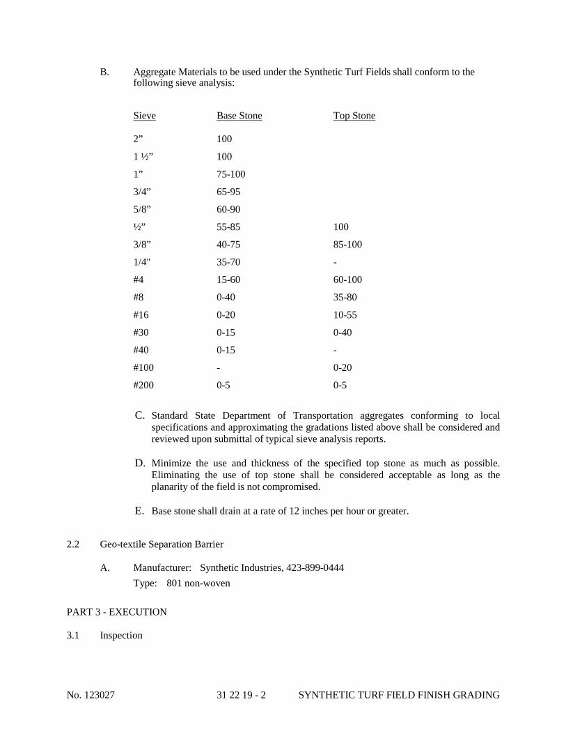
No. 123027 31 22 19 - 2 SYNTHETIC TURF FIELD FINISH GRADING
B. Aggregate Materials to be used under the Synthetic Turf Fields shall conform to the following sieve analysis:
Sieve Base Stone Top Stone 2” 100
1 ½” 100
1” 75-100
3/4” 65-95
5/8” 60-90
½” 55-85 100
3/8” 40-75 85-100
1/4" 35-70 -
#4 15-60 60-100
#8 0-40 35-80
#16 0-20 10-55
#30 0-15 0-40
#40 0-15 -
#100 - 0-20
#200 0-5 0-5
C. Standard State Department of Transportation aggregates conforming to local
specifications and approximating the gradations listed above shall be considered and reviewed upon submittal of typical sieve analysis reports.
D. Minimize the use and thickness of the specified top stone as much as possible. Eliminating the use of top stone shall be considered acceptable as long as the planarity of the field is not compromised.
E. Base stone shall drain at a rate of 12 inches per hour or greater.
2.2 Geo-textile Separation Barrier A. Manufacturer: Synthetic Industries, 423-899-0444 Type: 801 non-woven PART 3 - EXECUTION 3.1 Inspection

No. 123027 31 22 19 - 3 SYNTHETIC TURF FIELD FINISH GRADING
A. Verify site conditions and note irregularities affecting work of this section. 3.2 Subgrade Preparation
A. Grade and compact surface to eliminate wheel ruts, ridges, uneven areas and low spots. Remove debris, roots, branches, and stones in excess of 1/2 inch in size. Replace subsoil contaminated with petroleum products.
B. Upon completion of subgrade preparation Contractor shall meet on-site with Engineer
and Construction Manager for review and approval. 3.3 Placing Geo-textile Separation Barrier
A. Geo-textile shall be placed to cover the entire field overlapping all fabric edges 12” minimum. Separation barrier is to be placed into and through all drainage trenches.
3.4 Under-drain System A. The installation of the under-drain system must be coordinated with the installation of the
base stone to allow a cushion layer of stone to be installed over the under-drains to prevent crushing them by the stone trucks and placing equipment.
B. Backfill shall be placed carefully so as to protect from damaged to and maintain proper
placement of under drain system. C. Anchor and/or restrain under drain during placement of backfill material. D. Upstream ends of under drain shall be capped. E. Junctions shall be made with manufactured wyes and tees. 3.5 Placing Aggregate Material
A. Place the Base Stone starting at the access area of the field pushing it out across the field to cover the under-drains. Maintain levels, profiles, and contours.
B. Compact placed base aggregate material and put to correct grade. C. Place Top Stone in a uniform layer across field. Compact and laser grade to required
elevation and planarity. Compaction shall be done to achieve a minimum density of 95%.
3.6 Tolerances
A. Top of Base Stone: Plus or minus 0.04 foot from designated elevation. B. Top of Compacted Top Stone: Plus or minus 0.02 foot from designated elevation and
plus or minus 0.02 foot planarity in 10 feet. 3.7. Cleanup
A. Remove all excess materials and debris from site to proper disposal.
END OF SECTION 312219

No. 123027 31 23 19 - 1 DEWATERING
SECTION 312319
PART 1 - GENERAL
DEWATERING
1.1 RELATED DOCUMENTS
A. Drawings and general provisions of the Contract, including General and Supplementary Conditions and Division 01 Specification Sections, apply to this Section.
1.2 SUMMARY
A. Section includes construction dewatering.
B. Related Sections:
1. Division 01 Section "Construction Progress Documentation” for recording preexisting conditions and dewatering system progress.
2. Division 31 Section "Earth Moving" for excavating, backfilling, site grading, and for site utilities.
3. Division 31 Section "Excavation Support and Protection" for shoring, bracing, and sheet piling of excavations.
4. Division 33 Section "Subdrainage" for permanent foundation wall, underfloor, and footing drainage.
1.3 PERFORMANCE REQUIREMENTS
A. Dewatering Performance: Design, furnish, install, test, operate, monitor, and maintain dewatering system of sufficient scope, size, and capacity to control hydrostatic pressures and to lower, control, remove, and dispose of ground water and permit excavation and construction to proceed on dry, stable subgrades.
1. Delegated Design: Design dewatering system, including comprehensive engineering analysis by a qualified professional engineer, using performance requirements and design criteria indicated.
2. Continuously monitor and maintain dewatering operations to ensure erosion control, stability of excavations and constructed slopes, that excavation does not flood, and that damage to subgrades and permanent structures is prevented.
3. Prevent surface water from entering excavations by grading, dikes, or other means. 4. Accomplish dewatering without damaging existing buildings, structures, and site
improvements adjacent to excavation. 5. Remove dewatering system when no longer required for construction.

No. 123027 31 23 19 - 2 DEWATERING
1.4 SUBMITTALS
A. Shop Drawings: For dewatering system. Show arrangement, locations, and details of wells and well points; locations of risers, headers, filters, pumps, power units, and discharge lines; and means of discharge, control of sediment, and disposal of water.
1. Include layouts of piezometers and flow-measuring devices for monitoring performance of dewatering system.
2. Include a written plan for dewatering operations including control procedures to be adopted if dewatering problems arise.
B. Delegated-Design Submittal: For dewatering system indicated to comply with performance requirements and design criteria, including analysis data signed and sealed by the qualified professional engineer responsible for their preparation.
C. Qualification Data: For qualified Installer and professional engineer.
D. Field quality-control reports.
E. Other Informational Submittals:
1. Photographs: Show existing conditions of adjoining construction and site improvements that might be misconstrued as damage caused by dewatering operations.
1.5 QUALITY ASSURANCE
A. Installer Qualifications: An experienced installer that has specialized in design of dewatering systems and dewatering work.
B. Regulatory Requirements: Comply with governing EPA notification regulations before beginning dewatering. Comply with hauling and disposal regulations of authorities having jurisdiction.
C. Preinstallation Conference: Conduct conference at Project site.
1. Review methods and procedures related to dewatering including, but not limited to, the following:
a. Inspection and discussion of condition of site to be dewatered including coordination with temporary erosion control measures and temporary controls and protections.
b. Geotechnical report. c. Proposed site clearing and excavations. d. Existing utilities and subsurface conditions. e. Coordination for interruption, shutoff, capping, and continuation of utility services. f. Construction schedule. Verify availability of Installer's personnel, equipment, and
facilities needed to make progress and avoid delays. g. Testing and monitoring of dewatering system.
No. 123027 31 23 19 - 3 DEWATERING
1.6 PROJECT CONDITIONS
A. Interruption of Existing Utilities: Do not interrupt any utility serving facilities occupied by Owner or others unless permitted under the following conditions and then only after arranging to provide temporary utility according to requirements indicated:
1. Notify Architect and Owner no fewer than two days in advance of proposed interruption of utility.
2. Do not proceed with interruption of utility without Architect's or Owner's written permission.
B. Project-Site Information: A geotechnical report has been prepared for this Project and is available for information only. The opinions expressed in this report are those of geotechnical engineer and represent interpretations of subsoil conditions, tests, and results of analyses conducted by geotechnical engineer. Owner will not be responsible for interpretations or conclusions drawn from this data.
1. Make additional test borings and conduct other exploratory operations necessary for dewatering.
2. The geotechnical report is included elsewhere in the Project Manual.
C. Survey Work: Engage a qualified land surveyor or professional engineer to survey adjacent existing buildings, structures, and site improvements, establishing exact elevations at fixed points to act as benchmarks. Clearly identify benchmarks and record existing elevations.
1. During dewatering, regularly resurvey benchmarks, maintaining an accurate log of surveyed elevations for comparison with original elevations. Promptly notify Architect if changes in elevations occur or if cracks, sags, or other damage is evident in adjacent construction.
PART 2 - PRODUCTS (Not Used)
PART 3 - EXECUTION
3.1 PREPARATION
A. Protect structures, utilities, sidewalks, pavements, and other facilities from damage caused by settlement, lateral movement, undermining, washout, and other hazards created by dewatering operations.
1. Prevent surface water and subsurface or ground water from entering excavations, from ponding on prepared subgrades, and from flooding site and surrounding area.
2. Protect subgrades and foundation soils from softening and damage by rain or water accumulation.
B. Install dewatering system to ensure minimum interference with roads, streets, walks, and other adjacent occupied and used facilities.

No. 123027 31 23 19 - 4 DEWATERING
1. Do not close or obstruct streets, walks, or other adjacent occupied or used facilities without permission from Owner and authorities having jurisdiction. Provide alternate routes around closed or obstructed traffic ways if required by authorities having jurisdiction.
C. Provide temporary grading to facilitate dewatering and control of surface water.
D. Monitor dewatering systems continuously.
E. Promptly repair damages to adjacent facilities caused by dewatering.
F. Protect and maintain temporary erosion and sedimentation controls, which are specified in Division 31 Section "Site Clearing" during dewatering operations.
3.2 INSTALLATION
A. Install dewatering system utilizing wells, well points, or similar methods complete with pump equipment, standby power and pumps, filter material gradation, valves, appurtenances, water disposal, and surface-water controls.
1. Space well points or wells at intervals required to provide sufficient dewatering. 2. Use filters or other means to prevent pumping of fine sands or silts from the subsurface.
B. Before excavating below ground-water level, place system into operation to lower water to specified levels. Operate system continuously until drains, sewers, and structures have been constructed and fill materials have been placed or until dewatering is no longer required.
C. Provide an adequate system to lower and control ground water to permit excavation, construction of structures, and placement of fill materials on dry subgrades. Install sufficient dewatering equipment to drain water-bearing strata above and below bottom of foundations, drains, sewers, and other excavations.
1. Do not permit open-sump pumping that leads to loss of fines, soil piping, subgrade softening, and slope instability.
D. Reduce hydrostatic head in water-bearing strata below subgrade elevations of foundations, drains, sewers, and other excavations.
1. Maintain piezometric water level a minimum of 24 inches (1500 mm)
E. Dispose of water removed by dewatering in a manner that avoids endangering public health, property, and portions of work under construction or completed. Dispose of water and sediment in a manner that avoids inconvenience to others. Provide sumps, sedimentation tanks, and other flow-control devices as required by authorities having jurisdiction.
below surface of excavation.
F. Provide standby equipment on site, installed and available for immediate operation, to maintain dewatering on continuous basis if any part of system becomes inadequate or fails. If dewatering requirements are not satisfied due to inadequacy or failure of dewatering system, restore damaged structures and foundation soils at no additional expense to Owner.

No. 123027 31 23 19 - 5 DEWATERING
1. Remove dewatering system from Project site on completion of dewatering. Plug or fill well holes with sand or cut off and cap wells a minimum of 36 inches (900 mm)
G. Damages: Promptly repair damages to adjacent facilities caused by dewatering operations.
below overlying construction.
3.3 FIELD QUALITY CONTROL
A. Observation Wells: Provide, take measurements, and maintain at least the minimum number of observation wells or piezometers indicated; additional observation wells may be required by authorities having jurisdiction.
1. Observe and record daily elevation of ground water and piezometric water levels in observation wells.
2. Repair or replace, within 24 hours, observation wells that become inactive, damaged, or destroyed. In areas where observation wells are not functioning properly, suspend construction activities until reliable observations can be made. Add or remove water from observation-well risers to demonstrate that observation wells are functioning properly.
3. Fill observation wells, remove piezometers, and fill holes when dewatering is completed.
B. Provide continual observation to ensure that subsurface soils are not being removed by the dewatering operation.
END OF SECTION 31 23 19
No. 123027 31 50 00 - 1 EXCAVATION SUPPORT AND PROTECTION
SECTION 31 50 00
PART 1 - GENERAL
EXCAVATION SUPPORT AND PROTECTION
1.1 RELATED DOCUMENTS
A. Drawings and general provisions of the Contract, including General and Supplementary Conditions and Division 01 Specification Sections, apply to this Section.
1.2 SUMMARY
A. Section includes temporary excavation support and protection systems.
B. Related Sections:
1. Division 01 Section "Construction Progress Documentation" for recording preexisting conditions and excavation support and protection system progress.
2. Division 01 Section "Temporary Facilities and Controls" for temporary utilities and support facilities.
3. Division 31 Section "Dewatering" for dewatering system for excavations.
1.3 PERFORMANCE REQUIREMENTS
A. Furnish, install, monitor, and maintain excavation support and protection system capable of supporting excavation sidewalls and of resisting soil and hydrostatic pressure and superimposed and construction loads.
1. Prevent surface water from entering excavations by grading, dikes, or other means. 2. Install excavation support and protection systems without damaging existing buildings,
structures, and site improvements adjacent to excavation. 3. Monitor vibrations, settlements, and movements.
1.4 SUBMITTALS
A. Shop Drawings: For excavation support and protection system.
B. Delegated-Design Submittal: For excavation support and protection system indicated to comply with performance requirements and design criteria, including analysis data signed and sealed by the qualified professional engineer responsible for their preparation.
C. Coordinate first paragraph below with qualification requirements in Division 01 Section "Quality Requirements."Qualification Data: For qualified and professional engineer.

No. 123027 31 50 00 - 2 EXCAVATION SUPPORT AND PROTECTION
D. Other Informational Submittals:
1. Photographs or Videotape: Show existing conditions of adjacent construction and site improvements that might be misconstrued as damage caused by the absence of, the installation of, or the performance of excavation support and protection systems. Submit before Work begins.
2. Record Drawings: Identifying and locating capped utilities and other subsurface structural, electrical, or mechanical conditions.
a. Note locations and capping depth of wells and well points.
1.5 QUALITY ASSURANCE
A. Preinstallation Conference: Conduct conference at Project site.
1. Review methods and procedures related to excavation support and protection system including, but not limited to, the following:
a. Geotechnical report. b. Existing utilities and subsurface conditions. c. Proposed excavations. d. Proposed equipment. e. Monitoring of excavation support and protection system. f. Working area location and stability. g. Coordination with waterproofing. h. Abandonment or removal of excavation support and protection system.
1.6 PROJECT CONDITION
A. Interruption of Existing Utilities: Do not interrupt any utility serving facilities occupied by Owner or others unless permitted under the following conditions and then only after arranging to provide temporary utility according to requirements indicated:
1. Notify Architect and Owner no fewer than two days in advance of proposed interruption of utility.
2. Do not proceed with interruption of utility without Architect's or Owner's written permission.
B. Project-Site Information: A geotechnical report has been prepared for this Project and is available for information only. The opinions expressed in this report are those of geotechnical engineer and represent interpretations of subsoil conditions, tests, and results of analyses conducted by geotechnical engineer. Owner will not be responsible for interpretations or conclusions drawn from the data.
1. Make additional test borings and conduct other exploratory operations necessary for excavation support and protection.
2. The geotechnical report is included elsewhere in the Project Manual.

No. 123027 31 50 00 - 3 EXCAVATION SUPPORT AND PROTECTION
C. Survey Work: Engage a qualified land surveyor or professional engineer to survey adjacent existing buildings, structures, and site improvements; establish exact elevations at fixed points to act as benchmarks. Clearly identify benchmarks and record existing elevations.
1. During installation of excavation support and protection systems, regularly resurvey benchmarks, maintaining an accurate log of surveyed elevations and positions for comparison with original elevations and positions. Promptly notify Architect if changes in elevations or positions occur or if cracks, sags, or other damage is evident in adjacent construction.
PART 2 - PRODUCTS
2.1 MATERIALS
A. General: Provide materials that are either new or in serviceable condition.
B. Structural Steel: ASTM A 36/A 36M, ASTM A 690/A 690M, or ASTM A 992/A 992M.
C. Steel Sheet Piling: ASTM A 328/A 328M, ASTM A 572/A 572M, or ASTM A 690/A 690M; with continuous interlocks.
1. Corners: Roll-formed corner shape with continuous interlock.
D. Wood Lagging: Lumber, mixed hardwood, nominal rough thickness of size and strength required for application.
E. Cast-in-Place Concrete: ACI 301, of compressive strength required for application.
F. Reinforcing Bars: ASTM A 615/A 615M, Grade 60,
G. Tiebacks: Steel bars, ASTM A 722/A 722M.
deformed.
H. Tiebacks: Steel strand, ASTM A 416/A 416M.
PART 3 - EXECUTION
3.1 PREPARATION
A. Protect structures, utilities, sidewalks, pavements, and other facilities from damage caused by settlement, lateral movement, undermining, washout, and other hazards that could develop during excavation support and protection system operations.
1. Shore, support, and protect utilities encountered.
B. Install excavation support and protection systems to ensure minimum interference with roads, streets, walks, and other adjacent occupied and used facilities.
No. 123027 31 50 00 - 4 EXCAVATION SUPPORT AND PROTECTION
1. Do not close or obstruct streets, walks, or other adjacent occupied or used facilities without permission from Owner and authorities having jurisdiction. Provide alternate routes around closed or obstructed traffic ways if required by authorities having jurisdiction.
C. Locate excavation support and protection systems clear of permanent construction so that forming and finishing of concrete surfaces are not impeded.
D. Monitor excavation support and protection systems daily during excavation progress and for as long as excavation remains open. Promptly correct bulges, breakage, or other evidence of movement to ensure that excavation support and protection systems remain stable.
E. Promptly repair damages to adjacent facilities caused by installing excavation support and protection systems.
3.2 SOLDIER PILES AND LAGGING
A. Install steel soldier piles before starting excavation. Extend soldier piles below excavation grade level to depths adequate to prevent lateral movement. Space soldier piles at regular intervals not to exceed allowable flexural strength of wood lagging. Accurately align exposed faces of flanges to vary not more than 2 inches (50 mm)
B. Install wood lagging within flanges of soldier piles as excavation proceeds. Trim excavation as required to install lagging. Fill voids behind lagging with soil, and compact.
from a horizontal line and not more than 1:120 out of vertical alignment.
C. Install walls horizontally at locations indicated on Drawings and secure to soldier piles.
3.3 SHEET PILING
A. Before starting excavation, install one-piece sheet piling lengths and tightly interlock to form a continuous barrier. Accurately place the piling, using templates and guide frames unless otherwise recommended in writing by the sheet piling manufacturer. Limit vertical offset of adjacent sheet piling to 60 inches. Accurately align exposed faces of sheet piling to vary not more than 2 inches
3.4 TIEBACKS
from a horizontal line and not more than 1:120 out of vertical alignment. Cut tops of sheet piling to uniform elevation at top of excavation.
A. Tiebacks: Drill, install, grout, and tension tiebacks. Test load-carrying capacity of each tieback and replace and retest deficient tiebacks.
1. Test loading shall be observed by a qualified professional engineer responsible for design of excavation support and protection system.
2. Maintain tiebacks in place until permanent construction is able to withstand lateral soil and hydrostatic pressures.

No. 123027 31 50 00 - 5 EXCAVATION SUPPORT AND PROTECTION
3.5 BRACING
A. Bracing: Locate bracing to clear columns, floor framing construction, and other permanent work. If necessary to move brace, install new bracing before removing original brace.
1. Do not place bracing where it will be cast into or included in permanent concrete work unless otherwise approved by Architect.
2. Install internal bracing, if required, to prevent spreading or distortion of braced frames. 3. Maintain bracing until structural elements are supported by other bracing or until
permanent construction is able to withstand lateral earth and hydrostatic pressures.
3.6 REMOVAL AND REPAIRS
A. Remove excavation support and protection systems when construction has progressed sufficiently to support excavation and bear soil and hydrostatic pressures. Remove in stages to avoid disturbing underlying soils or damaging structures, pavements, facilities, and utilities.
1. Remove excavation support and protection systems to a minimum depth of 48 inches
2. Fill voids immediately with approved backfill compacted to density specified in Division 31 Section "Earth Moving."
below overlaying construction and abandon remainder.
3. Repair or replace, as approved by Architect, adjacent work damaged or displaced by removing excavation support and protection systems.
B. Leave excavation support and protection systems permanently in place.
END OF SECTION 31 50 00

No. 123027 32 12 16 - 1 ASPHALT PAVING
SECTION 321216
PART 1 - GENERAL
ASPHALT PAVING
1.1 RELATED DOCUMENTS
A. Drawings and general provisions of the Contract, including General and Supplementary Conditions and Division 01 Specification Sections, apply to this Section.
1.2 SUMMARY
A. Section Includes:
1. Cold milling of existing hot-mix asphalt pavement. 2. Hot-mix asphalt patching. 3. Hot-mix asphalt paving. 4. Hot-mix asphalt paving overlay. 5. Asphalt surface treatments. 6. Pavement-marking paint. 7. Traffic-calming devices. 8. Imprinted asphalt.
B. Related Sections: 1. Division 31 Section "Earth Moving" for aggregate subbase and base courses and for
aggregate pavement shoulders. 2. Division 32 Section "Concrete Paving Joint Sealants" for joint sealants and fillers at
paving terminations. 3. Division 32 Section "Unit Paving" for bituminous setting bed for pavers.
1.3 DEFINITION
A. Hot-Mix Asphalt Paving Terminology: Refer to ASTM D 8 for definitions of terms.
1.4 SUBMITTALS
A. Product Data: For each type of product indicated. Include technical data and tested physical and performance properties.
1. Job-Mix Designs: Certification, by authorities having jurisdiction, of approval of each job mix proposed for the Work.
2. Job-Mix Designs: For each job mix proposed for the Work.
B. Shop Drawings: Indicate pavement markings, lane separations, and defined parking spaces. Indicate, with international symbol of accessibility, spaces allocated for people with disabilities.

No. 123027 32 12 16 - 2 ASPHALT PAVING
C. Qualification Data: For qualified manufacturer.
D. Material Certificates: For each paving material, from manufacturer.
E. Material Test Reports: For each paving material.
1.5 QUALITY ASSURANCE
A. Manufacturer Qualifications: A paving-mix manufacturer registered with and approved by authorities having jurisdiction or the DOT of state in which Project is located.
B. Installer Qualifications: Imprinted-asphalt manufacturer's authorized installer who is trained and approved for installation of imprinted asphalt required for this Project.
C. Testing Agency Qualifications: Qualified according to ASTM D 3666 for testing indicated.
D. Regulatory Requirements: Comply with IDOT specifications for asphalt paving work.
1.6 DELIVERY, STORAGE, AND HANDLING
A. Deliver pavement-marking materials to Project site in original packages with seals unbroken and bearing manufacturer's labels containing brand name and type of material, date of manufacture, and directions for storage.
B. Store pavement-marking materials in a clean, dry, protected location within temperature range required by manufacturer. Protect stored materials from direct sunlight.
1.7 PROJECT CONDITIONS
A. Environmental Limitations: Do not apply asphalt materials if subgrade is wet or excessively damp, if rain is imminent or expected before time required for adequate cure, or if the following conditions are not met:
1. Prime Coat: Minimum surface temperature of 60 deg F (15.6 deg C)2. Tack Coat: Minimum surface temperature of
. 60 deg F (15.6 deg C)
3. Slurry Coat: Comply with weather limitations in ASTM D 3910. .
4. Asphalt Base Course: Minimum surface temperature of 40 deg F (4.4 deg C)
5. Asphalt Surface Course: Minimum surface temperature of
and rising at time of placement.
60 deg F (15.6 deg C)
B. Pavement-Marking Paint: Proceed with pavement marking only on clean, dry surfaces and at a minimum ambient or surface temperature of
at time of placement.
40 deg F (4.4 deg C) for oil-based materials 55 deg F (12.8 deg C) for water-based materials, and not exceeding 95 deg F (35 deg C).

No. 123027 32 12 16 - 3 ASPHALT PAVING
PART 2 - PRODUCTS
2.1 AGGREGATES
A. General: Use materials and gradations that have performed satisfactorily in previous installations.
B. Coarse Aggregate: ASTM D 692, sound; angular crushed stone, crushed gravel, or cured, crushed blast-furnace slag.
C. Fine Aggregate: AASHTO M 29, sharp-edged natural sand or sand prepared from stone, gravel, cured blast-furnace slag, or combinations thereof.
1. For hot-mix asphalt, limit natural sand to a maximum of 20 percent by weight of the total aggregate mass.
D. Mineral Filler: AASHTO M 17, rock or slag dust, hydraulic cement, or other inert material.
2.2 ASPHALT MATERIALS
A. Asphalt Binder: AASHTO M 320 or AASHTO MP 1a, PG 64-22.
B. Retain first paragraph below with option for viscosity- or penetration-graded asphalt cement if these materials are available and required. Viscosity testing measures properties more accurately than penetration testing. Insert viscosity or penetration grades below if required.
C. Asphalt Cement: ASTM D 946 for penetration-graded material.
D. Prime Coat: ASTM D 2027, medium-curing cutback asphalt, MC-250.
E. Prime Coat: Asphalt emulsion prime coat complying with IDOT requirements.
F. Tack Coat: AASHTO M 140 emulsified asphalt, or AASHTO M 208 cationic emulsified asphalt, slow setting, diluted in water, of suitable grade and consistency for application.
G. Fog Seal: AASHTO M 140 emulsified asphalt, or AASHTO M 208 cationic emulsified asphalt, slow setting, factory diluted in water, of suitable grade and consistency for application.
H. Water: Potable.
I. Undersealing Asphalt: AASHTO M 238, pumping consistency.
2.3 AUXILIARY MATERIALS
A. Herbicide: Commercial chemical for weed control, registered by the EPA. Provide in granular, liquid, or wettable powder form.
B. Sand: AASHTO M 29, Grade Nos. 2 or 3.
No. 123027 32 12 16 - 4 ASPHALT PAVING
C. Paving Geotextile: AASHTO M 288, nonwoven polypropylene; resistant to chemical attack, rot, and mildew; and specifically designed for paving applications.
D. Joint Sealant: AASHTO M 301 hot-applied, single-component, polymer-modified bituminous sealant.
E. Pavement-Marking Paint: Alkyd-resin type, lead and chromate free, ready mixed, complying with AASHTO M 248, Type F; colors complying with FS TT-P-1952.
1. Color: As indicated.
F. Pavement-Marking Paint: Latex, waterborne emulsion, lead and chromate free, ready mixed, complying with FS TT-P-1952, Type II, with drying time of less than 45 minutes.
1. Color: As indicated.
G. Glass Beads: AASHTO M 247, Type 1.
H. Wheel Stops: Precast, air-entrained concrete, 2500-psi (17.2-MPa) minimum compressive strength, 4-1/2 inches (115 mm) high by 9 inches (225 mm) wide by 72 inches (1800 mm)
1. Dowels: Galvanized steel,
long. Provide chamfered corners, drainage slots on underside, and holes for anchoring to substrate.
3/4-inch (19-mm) diameter, 10-inch (254-mm)
I. Wheel Stops: Solid, integrally colored, 96 percent recycled HDPE or commingled postconsumer and postindustrial recycled plastic; UV stabilized;
minimum length.
4 inches (100 mm) high by 6 inches (150 mm) wide by 72 inches (1800 mm)
1. Dowels: Galvanized steel,
long. Provide chamfered corners, drainage slots on underside, and holes for anchoring to substrate.
3/4-inch (19-mm) diameter, 10-inch (254-mm)
2. Adhesive: As recommended by wheel-stop manufacturer for application to asphalt pavement.
minimum length.
2.4 MIXES
A. Hot-Mix Asphalt: Dense, hot-laid, hot-mix asphalt plant mixes approved by authorities having jurisdiction; designed according to procedures in AI MS-2, "Mix Design Methods for Asphalt Concrete and Other Hot-Mix Types"; and complying with the following requirements:
1. Provide mixes with a history of satisfactory performance in geographical area where Project is located.
2. Base Course: IDOT Specifications. 3. Surface Course: IDOT Specifications.
B. Hot-Mix Asphalt: Dense, hot-laid, hot-mix asphalt plant mixes approved by authorities having jurisdiction and designed according to procedures in AI MS-2, "Mix Design Methods for Asphalt Concrete and Other Hot-Mix Types."

No. 123027 32 12 16 - 5 ASPHALT PAVING
1. Provide mixes with a history of satisfactory performance in geographical area where Project is located.
2. Provide mixes complying with composition, grading, and tolerance requirements in ASTM D 3515 for the following nominal, maximum aggregate sizes:
a. Base Course: 1 inch (25 mm)b. Surface Course:
. 1/2 inch (13 mm)
C. Emulsified-Asphalt Slurry: ASTM D 3910, Type 2e 3.
.
PART 3 - EXECUTION
3.1 EXAMINATION
A. Verify that subgrade is dry and in suitable condition to begin paving.
B. Proof-roll subgrade below pavements with heavy pneumatic-tired equipment to identify soft pockets and areas of excess yielding. Do not proof-roll wet or saturated subgrades.
C. Proceed with paving only after unsatisfactory conditions have been corrected.
3.2 COLD MILLING
A. Clean existing pavement surface of loose and deleterious material immediately before cold milling. Remove existing asphalt pavement by cold milling to grades and cross sections indicated.
1. Mill to a depth of 1-1/2 inches (38 mm) or as specified on the plans2. Mill to a uniform finished surface free of excessive gouges, grooves, and ridges.
.
3. Control rate of milling to prevent tearing of existing asphalt course. 4. Repair or replace curbs, manholes, and other construction damaged during cold milling. 5. Excavate and trim unbound-aggregate base course, if encountered, and keep material
separate from milled hot-mix asphalt. 6. Transport milled hot-mix asphalt to asphalt recycling facility. 7. Keep milled pavement surface free of loose material and dust.
3.3 PATCHING
A. Hot-Mix Asphalt Pavement: Saw cut perimeter of patch and excavate existing pavement section to sound base. Excavate rectangular or trapezoidal patches, extending 12 inches (300 mm)
B. Portland Cement Concrete Pavement: Break cracked slabs and roll as required to reseat concrete pieces firmly.
into adjacent sound pavement, unless otherwise indicated. Cut excavation faces vertically. Remove excavated material. Recompact existing unbound-aggregate base course to form new subgrade.

No. 123027 32 12 16 - 6 ASPHALT PAVING
1. Pump hot undersealing asphalt under rocking slab until slab is stabilized or, if necessary, crack slab into pieces and roll to reseat pieces firmly.
2. Remove disintegrated or badly cracked pavement. Excavate rectangular or trapezoidal patches, extending into adjacent sound pavement, unless otherwise indicated. Cut excavation faces vertically. Recompact existing unbound-aggregate base course to form new subgrade.
C. Tack Coat: Apply uniformly to vertical surfaces abutting or projecting into new, hot-mix asphalt paving at a rate of 0.05 to 0.15 gal./sq. yd. (0.2 to 0.7 L/sq. m)
1. Allow tack coat to cure undisturbed before applying hot-mix asphalt paving.
.
2. Avoid smearing or staining adjoining surfaces, appurtenances, and surroundings. Remove spillages and clean affected surfaces.
D. Patching: Fill excavated pavements with hot-mix asphalt base mix for full thickness of patch and, while still hot, compact flush with adjacent surface.
E. Patching: Partially fill excavated pavements with hot-mix asphalt base mix and, while still hot, compact. Cover asphalt base course with compacted, hot-mix surface layer finished flush with adjacent surfaces.
3.4 REPAIRS
A. Leveling Course: Install and compact leveling course consisting of hot-mix asphalt surface course to level sags and fill depressions deeper than 1 inch (25 mm)
1. Install leveling wedges in compacted lifts not exceeding
in existing pavements.
3 inches (75 mm)
B. Crack and Joint Filling: Remove existing joint filler material from cracks or joints to a depth of
thick.
1/4 inch (6 mm)
1. Clean cracks and joints in existing hot-mix asphalt pavement.
.
2. Use emulsified-asphalt slurry to seal cracks and joints less than 1/4 inch (6 mm)
3. Use hot-applied joint sealant to seal cracks and joints more than
wide. Fill flush with surface of existing pavement and remove excess.
1/4 inch (6 mm)
3.5 SURFACE PREPARATION
wide. Fill flush with surface of existing pavement and remove excess.
A. General: Immediately before placing asphalt materials, remove loose and deleterious material from substrate surfaces. Ensure that prepared subgrade is ready to receive paving.
B. Herbicide Treatment: Apply herbicide according to manufacturer's recommended rates and written application instructions. Apply to dry, prepared subgrade or surface of compacted-aggregate base before applying paving materials.
1. Mix herbicide with prime coat if formulated by manufacturer for that purpose.

No. 123027 32 12 16 - 7 ASPHALT PAVING
C. Prime Coat: Apply uniformly over surface of compacted unbound-aggregate base course at a rate of 0.25 to 0.50 gal./sq. yd. (0.7 to 2.3 L/sq. m)
1. If prime coat is not entirely absorbed within 24 hours after application, spread sand over surface to blot excess asphalt. Use enough sand to prevent pickup under traffic. Remove loose sand by sweeping before pavement is placed and after volatiles have evaporated.
. Apply enough material to penetrate and seal but not flood surface. Allow prime coat to cure.
2. Protect primed substrate from damage until ready to receive paving.
D. Tack Coat: Apply uniformly to surfaces of existing pavement at a rate of 0.05 to 0.15 gal./sq. yd. (0.2 to 0.7 L/sq. m)
1. Allow tack coat to cure undisturbed before applying hot-mix asphalt paving.
.
2. Avoid smearing or staining adjoining surfaces, appurtenances, and surroundings. Remove spillages and clean affected surfaces.
3.6 PAVING GEOTEXTILE INSTALLATION
A. Apply tack coat uniformly to existing pavement surfaces at a rate of 0.20 to 0.30 gal./sq. yd. (0.8 to 1.2 L/sq. m)
B. Place paving geotextile promptly according to manufacturer's written instructions. Broom or roll geotextile smooth and free of wrinkles and folds. Overlap longitudinal joints
.
4 inches (100 mm) and transverse joints 6 inches (150 mm)
1. Protect paving geotextile from traffic and other damage and place hot-mix asphalt paving overlay the same day.
.
3.7 HOT-MIX ASPHALT PLACING
A. Machine place hot-mix asphalt on prepared surface, spread uniformly, and strike off. Place asphalt mix by hand to areas inaccessible to equipment in a manner that prevents segregation of mix. Place each course to required grade, cross section, and thickness when compacted.
1. Place hot-mix asphalt base course in number of lifts and thicknesses indicated. 2. Place hot-mix asphalt surface course in single lift. 3. Spread mix at minimum temperature of 250 deg F (121 deg C)4. Begin applying mix along centerline of crown for crowned sections and on high side of
one-way slopes unless otherwise indicated.
.
5. Regulate paver machine speed to obtain smooth, continuous surface free of pulls and tears in asphalt-paving mat.
B. Place paving in consecutive strips not less than 10 feet (3 m)
1. After first strip has been placed and rolled, place succeeding strips and extend rolling to overlap previous strips. Complete a section of asphalt base course before placing asphalt surface course.
wide unless infill edge strips of a lesser width are required.
No. 123027 32 12 16 - 8 ASPHALT PAVING
C. Promptly correct surface irregularities in paving course behind paver. Use suitable hand tools to remove excess material forming high spots. Fill depressions with hot-mix asphalt to prevent segregation of mix; use suitable hand tools to smooth surface.
3.8 JOINTS
A. Construct joints to ensure a continuous bond between adjoining paving sections. Construct joints free of depressions, with same texture and smoothness as other sections of hot-mix asphalt course.
1. Clean contact surfaces and apply tack coat to joints. 2. Offset longitudinal joints, in successive courses, a minimum of 6 inches (150 mm)3. Offset transverse joints, in successive courses, a minimum of
. 24 inches (600 mm)
4. Construct transverse joints as described in AL MS-22 “Construction of Hot Mix Asphalt Pavements.
.
5. Compact joints as soon as hot-mix asphalt will bear roller weight without excessive displacement.
6. Compact asphalt at joints to a density within 2 percent of specified course density.
3.9 COMPACTION
A. General: Begin compaction as soon as placed hot-mix paving will bear roller weight without excessive displacement. Compact hot-mix paving with hot, hand tampers or with vibratory-plate compactors in areas inaccessible to rollers.
1. Complete compaction before mix temperature cools to 185 deg F (85 deg C)
B. Breakdown Rolling: Complete breakdown or initial rolling immediately after rolling joints and outside edge. Examine surface immediately after breakdown rolling for indicated crown, grade, and smoothness. Correct laydown and rolling operations to comply with requirements.
.
C. Intermediate Rolling: Begin intermediate rolling immediately after breakdown rolling while hot-mix asphalt is still hot enough to achieve specified density. Continue rolling until hot-mix asphalt course has been uniformly compacted to the following density:
1. Average Density: 96 percent of reference laboratory density according to AASHTO T 245, but not less than 94 percent nor greater than 100 percent.
2. Average Density: 92 percent of reference maximum theoretical density according to ASTM D 2041, but not less than 90 percent nor greater than 96 percent.
D. Finish Rolling: Finish roll paved surfaces to remove roller marks while hot-mix asphalt is still warm.
E. Edge Shaping: While surface is being compacted and finished, trim edges of pavement to proper alignment. Bevel edges while asphalt is still hot; compact thoroughly.
F. Repairs: Remove paved areas that are defective or contaminated with foreign materials and replace with fresh, hot-mix asphalt. Compact by rolling to specified density and surface smoothness.

No. 123027 32 12 16 - 9 ASPHALT PAVING
G. Protection: After final rolling, do not permit vehicular traffic on pavement until it has cooled and hardened.
H. Erect barricades to protect paving from traffic until mixture has cooled enough not to become marked.
3.10 INSTALLATION TOLERANCES
A. Pavement Thickness: Compact each course to produce the thickness indicated within the following tolerances:
1. Base Course: Plus or minus 1/2 inch (13 mm)2. Surface Course: Plus
. 1/4 inch (6 mm)
B. Pavement Surface Smoothness: Compact each course to produce a surface smoothness within the following tolerances as determined by using a
, no minus.
10-foot (3-m)
1. Base Course:
straightedge applied transversely or longitudinally to paved areas:
1/4 inch (6 mm)2. Surface Course:
. 1/8 inch (3 mm)
3. Crowned Surfaces: Test with crowned template centered and at right angle to crown. Maximum allowable variance from template is
.
1/4 inch (6 mm)
C. Traffic-Calming Devices: Compact and form asphalt to produce the contour indicated and within a tolerance of plus or minus
.
1/8 inch (3 mm)
3.11 SURFACE TREATMENTS
of height indicated above pavement surface.
A. Fog Seals: Apply fog seal at a rate of 0.10 to 0.15 gal./sq. yd. (0.45 to 0.7 L/sq. m)
B. Slurry Seals: Apply slurry coat in a uniform thickness according to ASTM D 3910 and allow to cure.
to existing asphalt pavement and allow to cure. With fine sand, lightly dust areas receiving excess fog seal.
1. Roll slurry seal to remove ridges and provide a uniform, smooth surface.
3.12 PAVEMENT MARKING
A. Do not apply pavement-marking paint until layout, colors, and placement have been verified with Architect.
B. Allow paving to age for 30 days before starting pavement marking.
C. Sweep and clean surface to eliminate loose material and dust.
D. Apply paint with mechanical equipment to produce pavement markings, of dimensions indicated, with uniform, straight edges. Apply at manufacturer's recommended rates to provide a minimum wet film thickness of 15 mils (0.4 mm).
No. 123027 32 12 16 - 10 ASPHALT PAVING
1. Broadcast glass beads uniformly into wet pavement markings at a rate of 6 lb/gal. (0.72 kg/L)
3.13 WHEEL STOPS
.
A. Install wheel stops in bed of adhesive as recommended by manufacturer.
B. Securely attach wheel stops to pavement with not less than two galvanized-steel dowels embedded at one-quarter to one-third points. Securely install dowels into pavement and bond to wheel stop. Recess head of dowel beneath top of wheel stop.
3.14 FIELD QUALITY CONTROL
A. Testing Agency: Owner will engage a qualified testing agency to perform tests and inspections.
B. Thickness: In-place compacted thickness of hot-mix asphalt courses will be determined according to ASTM D 3549.
C. Surface Smoothness: Finished surface of each hot-mix asphalt course will be tested for compliance with smoothness tolerances.
D. In-Place Density: Testing agency will take samples of uncompacted paving mixtures and compacted pavement according to AASHTO T 168.
1. Reference maximum theoretical density will be determined by averaging results from four samples of hot-mix asphalt-paving mixture delivered daily to site, prepared according to ASTM D 2041, and compacted according to job-mix specifications.
2. In-place density of compacted pavement will be determined by testing core samples according to ASTM D 1188 or ASTM D 2726.
a. One core sample will be taken for every 1000 sq. yd. (836 sq. m)
b. Field density of in-place compacted pavement may also be determined by nuclear method according to ASTM D 2950 and correlated with ASTM D 1188 or ASTM D 2726.
or less of installed pavement, with no fewer than 3 cores taken.
E. Replace and compact hot-mix asphalt where core tests were taken.
F. Remove and replace or install additional hot-mix asphalt where test results or measurements indicate that it does not comply with specified requirements.
3.15 DISPOSAL
A. Except for material indicated to be recycled, remove excavated materials from Project site and legally dispose of them in an EPA-approved landfill.
1. Do not allow milled materials to accumulate on-site.
END OF SECTION 32 12 16

No. 123027 32 13 13 - 1 CONCRETE PAVING
SECTION 321313
PART 1 - GENERAL
CONCRETE PAVING
1.1 RELATED DOCUMENTS
A. Drawings and general provisions of the Contract, including General and Supplementary Conditions and Division 01 Specification Sections, apply to this Section.
1.2 SUMMARY
A. Section Includes:
1. Driveways. 2. Parking lots. 3. Curbs and gutters. 4. Walks.
B. Related Sections:
1. Division 03 Section "Cast-in-Place Concrete" for general building applications of concrete.
2. Division 32 Section "Concrete Paving Joint Sealants" for joint sealants in expansion and contraction joints within concrete paving and in joints between concrete paving and asphalt paving or adjacent construction.
1.3 DEFINITIONS
A. Cementitious Materials: Portland cement alone or in combination with one or more of blended hydraulic cement, fly ash and other pozzolans, and ground granulated blast-furnace slag.
1.4 QUALITY ASSURANCE
A. Detectable Warning Installer Qualifications: An employer of workers trained and approved by manufacturer of stamped concrete paving systems.
B. Ready-Mix-Concrete Manufacturer Qualifications: A firm experienced in manufacturing ready-mixed concrete products and that complies with ASTM C 94/C 94M requirements for production facilities and equipment.
1. Manufacturer certified according to NRMCA's "Certification of Ready Mixed Concrete Production Facilities" (Quality Control Manual - Section 3, "Plant Certification Checklist").

No. 123027 32 13 13 - 2 CONCRETE PAVING
C. Testing Agency Qualifications: Qualified according to ASTM C 1077 and ASTM E 329 for testing indicated.
1. Personnel conducting field tests shall be qualified as ACI Concrete Field Testing Technician, Grade 1, according to ACI CP-1 or an equivalent certification program.
D. Concrete Testing Service: Engage a qualified testing agency to perform material evaluation tests and design concrete mixtures.
PART 2 - PRODUCTS
2.1 FORMS
A. Form Materials: Plywood, metal, metal-framed plywood, or other approved panel-type materials to provide full-depth, continuous, straight, and smooth exposed surfaces.
1. Use flexible or uniformly curved forms for curves with a radius of 100 feet (30.5 m)
B. Form-Release Agent: Commercially formulated form-release agent that will not bond with, stain, or adversely affect concrete surfaces and that will not impair subsequent treatments of concrete surfaces.
or less.
2.2 STEEL REINFORCEMENT
A. Plain-Steel Welded Wire Reinforcement: ASTM A 185/A 185M, fabricated from as-drawn steel wire into flat sheets.
B. Deformed-Steel Welded Wire Reinforcement: ASTM A 497/A 497M, flat sheet.
C. Epoxy-Coated Welded Wire Reinforcement: ASTM A 884/A 884M, Class A, plain steel.
D. Reinforcing Bars: ASTM A 615/A 615M, Grade 60 (Grade 420)
E. Galvanized Reinforcing Bars: ASTM A 767/A 767M, Class II zinc coated, hot-dip galvanized after fabrication and bending; with ASTM A 615/A 615M,
; deformed.
Grade 60 (Grade 420)
F. Epoxy-Coated Reinforcing Bars: ASTM A 775/A 775M or ASTM A 934/A 934M; with ASTM A 615/A 615M,
deformed bars.
Grade 60 (Grade 420)
G. Steel Bar Mats: ASTM A 184/A 184M; with ASTM A 615/A 615M,
deformed bars.
Grade 60 (Grade 420)
H. Plain-Steel Wire: ASTM A 82/A 82M, as drawn.
, deformed bars; assembled with clips.
I. Deformed-Steel Wire: ASTM A 496/A 496M.

No. 123027 32 13 13 - 3 CONCRETE PAVING
J. Joint Dowel Bars: ASTM A 615/A 615M, Grade 60 (Grade 420)
K. Epoxy-Coated, Joint Dowel Bars: ASTM A 775/A 775M; with ASTM A 615/A 615M,
plain-steel bars. Cut bars true to length with ends square and free of burrs.
Grade 60 (Grade 420)
L. Tie Bars: ASTM A 615/A 615M,
, plain-steel bars.
Grade 60 (Grade 420)
M. Hook Bolts:
, deformed.
ASTM A 307, Grade A (ASTM F 568M, Property Class 4.6)
N. Bar Supports: Bolsters, chairs, spacers, and other devices for spacing, supporting, and fastening reinforcing bars, welded wire reinforcement, and dowels in place. Manufacture bar supports according to CRSI's "Manual of Standard Practice" from steel wire, plastic, or precast concrete of greater compressive strength than concrete specified, and as follows:
, internally and externally threaded. Design hook-bolt joint assembly to hold coupling against paving form and in position during concreting operations, and to permit removal without damage to concrete or hook bolt.
1. Equip wire bar supports with sand plates or horizontal runners where base material will not support chair legs.
2. For epoxy-coated reinforcement, use epoxy-coated or other dielectric-polymer-coated wire bar supports.
O. Epoxy Repair Coating: Liquid, two-part, epoxy repair coating, compatible with epoxy coating on reinforcement.
P. Zinc Repair Material: ASTM A 780.
2.3 CONCRETE MATERIALS
A. Cementitious Material: Use the following cementitious materials, of same type, brand, and source throughout Project:
1. Portland Cement: ASTM C 150, gray portland cement Type II
B. Exposed Aggregate: Selected, hard, and durable; washed; free of materials with deleterious reactivity to cement or that cause staining; from a single source, with gap-graded coarse aggregate as follows:
1. Aggregate Sizes: 3/4 to 1 inch (19 to 25 mm) 1/2 to 3/4 inch (13 to 19 mm) 3/8 to 5/8 inch (10 to 16 mm)
C. Water: Potable and complying with ASTM C 94/C 94M.
nominal.
D. Air-Entraining Admixture: ASTM C 260.
E. Chemical Admixtures: Admixtures certified by manufacturer to be compatible with other admixtures and to contain not more than 0.1 percent water-soluble chloride ions by mass of cementitious material.
1. Water-Reducing Admixture: ASTM C 494/C 494M, Type A.
No. 123027 32 13 13 - 4 CONCRETE PAVING
2. Retarding Admixture: ASTM C 494/C 494M, Type B. 3. Water-Reducing and Retarding Admixture: ASTM C 494/C 494M, Type D. 4. High-Range, Water-Reducing Admixture: ASTM C 494/C 494M, Type F. 5. High-Range, Water-Reducing and Retarding Admixture: ASTM C 494/C 494M,
Type G. 6. Plasticizing and Retarding Admixture: ASTM C 1017/C 1017M, Type II.
2.4 CURING MATERIALS
A. Absorptive Cover: AASHTO M 182, Class 2, burlap cloth made from jute or kenaf, weighing approximately 9 oz./sq. yd. (305 g/sq. m)
B. Moisture-Retaining Cover: ASTM C 171, polyethylene film or white burlap-polyethylene sheet.
dry.
C. Water: Potable.
D. Evaporation Retarder: Waterborne, monomolecular, film forming, manufactured for application to fresh concrete.
1. Products:
a. Axim Italcementi Group, Inc.; Caltexol CIMFILM. b. BASF Construction Chemicals, LLC; Confilm. c. ChemMasters; Spray-Film. d. Conspec by Dayton Superior; Aquafilm. e. Dayton Superior Corporation; Sure Film (J-74). f. Edoco by Dayton Superior; BurkeFilm. g. Euclid Chemical Company (The), an RPM company; Eucobar. h. Kaufman Products, Inc.; VaporAid. i. Lambert Corporation; LAMBCO Skin. j. L&M Construction Chemicals, Inc.; E-CON. k. Meadows, W. R., Inc.; EVAPRE. l. Metalcrete Industries; Waterhold. m. Nox-Crete Products Group; MONOFILM. n. Sika Corporation, Inc.; SikaFilm. o. Symons by Dayton Superior; Finishing Aid. p. Vexcon Chemicals Inc.; Certi-Vex EnvioAssist.
E. Clear, Waterborne, Membrane-Forming Curing Compound: ASTM C 309, Type 1, Class B, dissipating.
1. Products:
a. Anti-Hydro International, Inc.; A-H Curing Compound #2 DR WB. b. ChemMasters; Safe-Cure Clear. c. Conspec by Dayton Superior; Resin Cure. d. Dayton Superior Corporation; Day-Chem Rez Cure (J-11-W). e. Edoco by Dayton Superior; Resin Emulsion Cure V.O.C. (Type II). f. Euclid Chemical Company (The), an RPM company; Kurez W VOX.

No. 123027 32 13 13 - 5 CONCRETE PAVING
g. Kaufman Products, Inc.; Thinfilm 420. h. Lambert Corporation; AQUA KURE - CLEAR. i. L&M Construction Chemicals, Inc.; L&M CURE R. j. Meadows, W. R., Inc.; 1100-CLEAR SERIES. k. Nox-Crete Products Group; Resin Cure E. l. Symons by Dayton Superior; Resi-Chem Clear. m. Tamms Industries, Inc., Euclid Chemical Company (The); TAMMSCURE
WB 30C. n. Vexcon Chemicals Inc.; Certi-Vex Enviocure 100.
F. White, Waterborne, Membrane-Forming Curing Compound: ASTM C 309, Type 2, Class B, dissipating.
1. Products:
a. Anti-Hydro International, Inc.; A-H Curing Compound #2 WP WB. b. ChemMasters; Safe-Cure 2000. c. Conspec by Dayton Superior; Resin Cure. d. Dayton Superior Corporation; Day-Chem White Pigmented Cure (J-10-W). e. Edoco by Dayton Superior; Resin Emulsion Cure V.O.C. (Type II). f. Euclid Chemical Company (The), an RPM company; Kurez VOX White
Pigmented. g. Kaufman Products, Inc.; Thinfilm 450. h. Lambert Corporation; AQUA KURE - WHITE. i. L&M Construction Chemicals, Inc.; L&M CURE R-2. j. Meadows, W. R., Inc.; 1100-WHITE SERIES. k. Symons by Dayton Superior; Resi-Chem White. l. Vexcon Chemicals Inc.; Certi-Vex Enviocure White 100.
2.5 RELATED MATERIALS
A. Joint Fillers: ASTM D 1751, asphalt-saturated cellulosic fiber in preformed strips.
B. Bonding Agent: ASTM C 1059, Type II, non-redispersible, acrylic emulsion or styrene butadiene.
C. Epoxy Bonding Adhesive: ASTM C 881/C 881M, two-component epoxy resin capable of humid curing and bonding to damp surfaces; of class suitable for application temperature, of grade complying with requirements, and of the following types:
1. Types IV and V, load bearing, for bonding hardened or freshly mixed concrete to hardened concrete.
D. Chemical Surface Retarder: Water-soluble, liquid, set retarder with color dye, for horizontal concrete surface application, capable of temporarily delaying final hardening of concrete to a depth of 1/8 to 1/4 inch (3 to 6 mm)
.

No. 123027 32 13 13 - 6 CONCRETE PAVING
1. Products:
a. ChemMasters; Exposee. b. Conspec by Dayton Superior; Delay S. c. Euclid Chemical Company (The), an RPM company; Surface Retarder Formula S. d. Kaufman Products, Inc.; Expose. e. Metalcrete Industries; Surftard. f. Nox-Crete Products Group; CRETE-NOX TA. g. Scofield, L. M. Company; LITHOTEX Top Surface Retarder. h. Sika Corporation, Inc.; Rugasol-S. i. Vexcon Chemicals Inc.; Certi-Vex Envioset.
E. Rock Salt: Sodium chloride crystals, kiln dried, coarse gradation with 100 percent passing 3/8-inch (9.5-mm) sieve and 85 percent retained on a No. 8 (2.36-mm)
2.6 PAVEMENT MARKINGS
sieve.
A. Pavement-Marking Paint: Alkyd-resin type, lead and chromate free, ready mixed, complying with AASHTO M 248, Type N; colors complying with FS TT-P-1952.
1. Color: As indicated.
B. Glass Beads: AASHTO M 247, Type 1.
2.7 WHEEL STOPS
A. Wheel Stops: Precast, air-entrained concrete, 2500-psi minimum compressive strength, 4-1/2 inches high by 9 inches wide by 72 inches
1. Dowels: Galvanized steel,
long. Provide chamfered corners and drainage slots on underside and holes for anchoring to substrate.
3/4 inch (19 mm) in diameter, 10-inch
2.8 CONCRETE MIXING
minimum length.
A. Ready-Mixed Concrete: Measure, batch, and mix concrete materials and concrete according to ASTM C 94/C 94M and ASTM C 1116/C 1116M. Furnish batch certificates for each batch discharged and used in the Work.
1. When air temperature is between 85 and 90 deg F reduce mixing and delivery time from 1-1/2 hours to 75 minutes; when air temperature is above 90 deg F
B. Project-Site Mixing: Measure, batch, and mix concrete materials and concrete according to ASTM C 94/C 94M. Mix concrete materials in appropriate drum-type batch machine mixer.
reduce mixing and delivery time to 60 minutes.

No. 123027 32 13 13 - 7 CONCRETE PAVING
1. For concrete batches of 1 cu. yd.
2. For concrete batches larger than
or smaller, continue mixing at least 1-1/2 minutes, but not more than 5 minutes after ingredients are in mixer, before any part of batch is released.
1 cu. yd. increase mixing time by 15 seconds for each additional 1 cu. yd.
3. Provide batch ticket for each batch discharged and used in the Work, indicating Project identification name and number, date, mixture type, mixing time, quantity, and amount of water added.
PART 3 - EXECUTION
3.1 EXAMINATION
A. Examine exposed subgrades and subbase surfaces for compliance with requirements for dimensional, grading, and elevation tolerances.
B. Proof-roll prepared subbase surface below concrete paving to identify soft pockets and areas of excess yielding.
1. Completely proof-roll subbase in one direction and repeat in perpendicular direction. Limit vehicle speed to
2. Proof-roll with a pneumatic-tired and loaded, 10-wheel, tandem-axle dump truck weighing not less than
3 mph.
15 tons3. Correct subbase with soft spots and areas of pumping or rutting exceeding depth of [
. 1/2
inch
C. Proceed with installation only after unsatisfactory conditions have been corrected.
according to requirements in Division 31 Section "Earth Moving."
3.2 PREPARATION
A. Remove loose material from compacted subbase surface immediately before placing concrete.
3.3 EDGE FORMS AND SCREED CONSTRUCTION
A. Set, brace, and secure edge forms, bulkheads, and intermediate screed guides to required lines, grades, and elevations. Install forms to allow continuous progress of work and so forms can remain in place at least 24 hours after concrete placement.
B. Clean forms after each use and coat with form-release agent to ensure separation from concrete without damage.
3.4 STEEL REINFORCEMENT
A. General: Comply with CRSI's "Manual of Standard Practice" for fabricating, placing, and supporting reinforcement.
B. Clean reinforcement of loose rust and mill scale, earth, ice, or other bond-reducing materials.

No. 123027 32 13 13 - 8 CONCRETE PAVING
C. Arrange, space, and securely tie bars and bar supports to hold reinforcement in position during concrete placement. Maintain minimum cover to reinforcement.
D. Install welded wire reinforcement in lengths as long as practicable. Lap adjoining pieces at least one full mesh, and lace splices with wire. Offset laps of adjoining widths to prevent continuous laps in either direction.
E. Zinc-Coated Reinforcement: Use galvanized-steel wire ties to fasten zinc-coated reinforcement. Repair cut and damaged zinc coatings with zinc repair material.
F. Epoxy-Coated Reinforcement: Use epoxy-coated steel wire ties to fasten epoxy-coated reinforcement. Repair cut and damaged epoxy coatings with epoxy repair coating according to ASTM D 3963/D 3963M.
G. Install fabricated bar mats in lengths as long as practicable. Handle units to keep them flat and free of distortions. Straighten bends, kinks, and other irregularities, or replace units as required before placement. Set mats for a minimum 2-inch
3.5 JOINTS
overlap of adjacent mats.
A. General: Form construction, isolation, and contraction joints and tool edges true to line, with faces perpendicular to surface plane of concrete. Construct transverse joints at right angles to centerline unless otherwise indicated.
1. When joining existing paving, place transverse joints to align with previously placed joints unless otherwise indicated.
B. Construction Joints: Set construction joints at side and end terminations of paving and at locations where paving operations are stopped for more than one-half hour unless paving terminates at isolation joints.
1. Continue steel reinforcement across construction joints unless otherwise indicated. Do not continue reinforcement through sides of paving strips unless otherwise indicated.
2. Provide tie bars at sides of paving strips where indicated. 3. Butt Joints: Use bonding agent at joint locations where fresh concrete is placed against
hardened or partially hardened concrete surfaces. 4. Keyed Joints: Provide preformed keyway-section forms or bulkhead forms with keys
unless otherwise indicated. Embed keys at least 1-1/2 inches5. Doweled Joints: Install dowel bars and support assemblies at joints where indicated.
Lubricate or coat with asphalt one-half of dowel length to prevent concrete bonding to one side of joint.
into concrete.
C. Isolation Joints: Form isolation joints of preformed joint-filler strips abutting concrete curbs, catch basins, manholes, inlets, structures, other fixed objects, and where indicated.
1. Locate expansion joints at intervals of 50 feet2. Extend joint fillers full width and depth of joint.
unless otherwise indicated.
3. Terminate joint filler not less than 1/2 inch or more than 1 inch below finished surface if joint sealant is indicated.

No. 123027 32 13 13 - 9 CONCRETE PAVING
4. Place top of joint filler flush with finished concrete surface if joint sealant is not indicated.
5. Furnish joint fillers in one-piece lengths. Where more than one length is required, lace or clip joint-filler sections together.
6. During concrete placement, protect top edge of joint filler with metal, plastic, or other temporary preformed cap. Remove protective cap after concrete has been placed on both sides of joint.
D. Contraction Joints: Form weakened-plane contraction joints, sectioning concrete into areas as indicated. Construct contraction joints for a depth equal to at least one-fourth of the concrete thickness, as follows:
1. Grooved Joints: Form contraction joints after initial floating by grooving and finishing each edge of joint with grooving tool to a radius. Repeat grooving of contraction joints after applying surface finishes. Eliminate grooving-tool marks on concrete surfaces.
2. Sawed Joints: Form contraction joints with power saws equipped with shatterproof abrasive or diamond-rimmed blades. Cut 1/8-inch
3. Doweled Contraction Joints: Install dowel bars and support assemblies at joints where indicated. Lubricate or coat with asphalt one-half of dowel length to prevent concrete bonding to one side of joint.
wide joints into concrete when cutting action will not tear, abrade, or otherwise damage surface and before developing random contraction cracks.
E. Edging: After initial floating, tool edges of paving, gutters, curbs, and joints in concrete with an edging tool to a 3/8-inch
3.6 CONCRETE PLACEMENT
radius. Repeat tooling of edges after applying surface finishes. Eliminate edging-tool marks on concrete surfaces.
A. Before placing concrete, inspect and complete formwork installation, steel reinforcement, and items to be embedded or cast-in.
B. Remove snow, ice, or frost from subbase surface and steel reinforcement before placing concrete. Do not place concrete on frozen surfaces.
C. Moisten subbase to provide a uniform dampened condition at time concrete is placed. Do not place concrete around manholes or other structures until they are at required finish elevation and alignment.
D. Comply with ACI 301
E. Do not add water to concrete during delivery or at Project site. Do not add water to fresh concrete after testing.
requirements for measuring, mixing, transporting, and placing concrete.
F. Deposit and spread concrete in a continuous operation between transverse joints. Do not push or drag concrete into place or use vibrators to move concrete into place.

No. 123027 32 13 13 - 10 CONCRETE PAVING
G. Consolidate concrete according to ACI 301
1. Consolidate concrete along face of forms and adjacent to transverse joints with an internal vibrator. Keep vibrator away from joint assemblies, reinforcement, or side forms. Use only square-faced shovels for hand spreading and consolidation. Consolidate with care to prevent dislocating reinforcement dowels and joint devices.
by mechanical vibrating equipment supplemented by hand spading, rodding, or tamping.
H. Screed paving surface with a straightedge and strike off.
I. Commence initial floating using bull floats or darbies to impart an open-textured and uniform surface plane before excess moisture or bleed water appears on the surface. Do not further disturb concrete surfaces before beginning finishing operations or spreading surface treatments.
J. Curbs and Gutters: Use design mixture for automatic machine placement. Produce curbs and gutters to required cross section, lines, grades, finish, and jointing.
K. Slip-Form Paving: Use design mixture for automatic machine placement. Produce paving to required thickness, lines, grades, finish, and jointing.
1. Compact subbase and prepare subgrade of sufficient width to prevent displacement of slip-form paving machine during operations.
L. Cold-Weather Placement: Protect concrete work from physical damage or reduced strength that could be caused by frost, freezing, or low temperatures. Comply with ACI 306.1 and the following:
1. When air temperature has fallen to or is expected to fall below 40 deg F uniformly heat water and aggregates before mixing to obtain a concrete mixture temperature of not less than 50 deg F and not more than 80 deg F
2. Do not use frozen materials or materials containing ice or snow. at point of placement.
3. Do not use calcium chloride, salt, or other materials containing antifreeze agents or chemical accelerators unless otherwise specified and approved in design mixtures.
M. Hot-Weather Placement: Comply with ACI 301
1. Cool ingredients before mixing to maintain concrete temperature below
and as follows when hot-weather conditions exist:
90 deg F
2. Cover steel reinforcement with water-soaked burlap so steel temperature will not exceed ambient air temperature immediately before embedding in concrete.
at time of placement. Chilled mixing water or chopped ice may be used to control temperature, provided water equivalent of ice is calculated in total amount of mixing water. Using liquid nitrogen to cool concrete is Contractor's option.
3. Fog-spray forms, steel reinforcement, and subgrade just before placing concrete. Keep subgrade moisture uniform without standing water, soft spots, or dry areas.
3.7 FLOAT FINISHING
A. General: Do not add water to concrete surfaces during finishing operations.

No. 123027 32 13 13 - 11 CONCRETE PAVING
B. Float Finish: Begin the second floating operation when bleed-water sheen has disappeared and concrete surface has stiffened sufficiently to permit operations. Float surface with power-driven floats or by hand floating if area is small or inaccessible to power units. Finish surfaces to true planes. Cut down high spots and fill low spots. Refloat surface immediately to uniform granular texture.
1. Burlap Finish: Drag a seamless strip of damp burlap across float-finished concrete, perpendicular to line of traffic, to provide a uniform, gritty texture.
2. Medium-to-Fine-Textured Broom Finish: Draw a soft-bristle broom across float-finished concrete surface perpendicular to line of traffic to provide a uniform, fine-line texture.
3. Medium-to-Coarse-Textured Broom Finish: Provide a coarse finish by striating float-finished concrete surface 1/16 to 1/8 inch (1.6 to 3 mm)
3.8 CONCRETE PROTECTION AND CURING
deep with a stiff-bristled broom, perpendicular to line of traffic.
A. General: Protect freshly placed concrete from premature drying and excessive cold or hot temperatures.
B. Comply with ACI 306.1 for cold-weather protection.
C. Evaporation Retarder: Apply evaporation retarder to concrete surfaces if hot, dry, or windy conditions cause moisture loss approaching 0.2 lb/sq. ft. x h (1 kg/sq. m x h)
D. Begin curing after finishing concrete but not before free water has disappeared from concrete surface.
before and during finishing operations. Apply according to manufacturer's written instructions after placing, screeding, and bull floating or darbying concrete but before float finishing.
E. Curing Methods: Cure concrete by moisture curing, moisture-retaining-cover curing, and curing compound or a combination of these as follows:
1. Moisture Curing: Keep surfaces continuously moist for not less than seven days with the following materials:
a. Water. b. Continuous water-fog spray. c. Absorptive cover, water saturated and kept continuously wet. Cover concrete
surfaces and edges with 12-inch
2. Moisture-Retaining-Cover Curing: Cover concrete surfaces with moisture-retaining cover, placed in widest practicable width, with sides and ends lapped at least
lap over adjacent absorptive covers.
12 inches (300 mm)
3. Curing Compound: Apply uniformly in continuous operation by power spray or roller according to manufacturer's written instructions. Recoat areas that have been subjected to heavy rainfall within three hours after initial application. Maintain continuity of coating, and repair damage during curing period.
and sealed by waterproof tape or adhesive. Immediately repair any holes or tears occurring during installation or curing period using cover material and waterproof tape.
No. 123027 32 13 13 - 12 CONCRETE PAVING
3.9 PAVING TOLERANCES
A. Comply with tolerances in ACI 117 and as follows:
1. Elevation: 1/4 inch2. Thickness: Plus
. 3/8 inch, minus 1/4 inch
3. Surface: Gap below .
10-foot- long, unleveled straightedge not to exceed 1/2 inch4. Alignment of Tie-Bar End Relative to Line Perpendicular to Paving Edge:
. 1/4 inch per
12 inches5. Lateral Alignment and Spacing of Dowels:
of tie bar. 1 inch
6. Vertical Alignment of Dowels: .
1/4 inch7. Alignment of Dowel-Bar End Relative to Line Perpendicular to Paving Edge:
. 1/4 inch
per 12 inches8. Joint Spacing:
of dowel. 3 inches
9. Contraction Joint Depth: Plus
1/4 inch10. Joint Width: Plus
no minus. 1/8 inch
3.10 PAVEMENT MARKING
, no minus.
A. Do not apply pavement-marking paint until layout, colors, and placement have been verified with Architect.
B. Allow concrete paving to cure for a minimum of 28 days and be dry before starting pavement marking.
C. Sweep and clean surface to eliminate loose material and dust.
D. Apply paint with mechanical equipment to produce markings of dimensions indicated with uniform, straight edges. Apply at manufacturer's recommended rates to provide a minimum wet film thickness of 15 mils
1. Apply graphic symbols and lettering with paint-resistant, die-cut stencils, firmly secured to concrete surface. Mask an extended area beyond edges of each stencil to prevent paint application beyond stencil. Apply paint so that it cannot run beneath stencil.
2. Broadcast glass beads uniformly into wet markings at a rate of
3.11 WHEEL STOPS
6 lb/gal.
A. Install wheel stops in bed of adhesive applied as recommended by manufacturer.
B. Securely attach wheel stops to paving with not less than two galvanized-steel dowels located at one-quarter to one-third points. Install dowels in drilled holes in the paving and bond dowels to wheel stop. Recess head of dowel beneath top of wheel stop.
3.12 FIELD QUALITY CONTROL
A. Testing Agency: Owner will engage a qualified testing agency to perform tests and inspections.

No. 123027 32 13 13 - 13 CONCRETE PAVING
B. Testing Services: Testing of composite samples of fresh concrete obtained according to ASTM C 172 shall be performed according to the following requirements:
1. Testing Frequency: Obtain at least one composite sample for each 100 cu. yd.
a. When frequency of testing will provide fewer than five compressive-strength tests for each concrete mixture, testing shall be conducted from at least five randomly selected batches or from each batch if fewer than five are used.
or fraction thereof of each concrete mixture placed each day.
2. Slump: ASTM C 143/C 143M; one test at point of placement for each composite sample, but not less than one test for each day's pour of each concrete mixture. Perform additional tests when concrete consistency appears to change.
3. Air Content: ASTM C 231, pressure method; one test for each composite sample, but not less than one test for each day's pour of each concrete mixture.
4. Concrete Temperature: ASTM C 1064/C 1064M; one test hourly when air temperature is 40 deg F and below and when it is 80 deg F
5. Compression Test Specimens: ASTM C 31/C 31M; cast and laboratory cure one set of three standard cylinder specimens for each composite sample.
and above, and one test for each composite sample.
6. Compressive-Strength Tests: ASTM C 39/C 39M; test one specimen at seven days and two specimens at 28 days.
a. A compressive-strength test shall be the average compressive strength from two specimens obtained from same composite sample and tested at 28 days.
C. Strength of each concrete mixture will be satisfactory if average of any three consecutive compressive-strength tests equals or exceeds specified compressive strength and no compressive-strength test value falls below specified compressive strength by more than 500 psi
D. Test results shall be reported in writing to Architect, concrete manufacturer, and Contractor within 48 hours of testing. Reports of compressive-strength tests shall contain Project identification name and number, date of concrete placement, name of concrete testing and inspecting agency, location of concrete batch in Work, design compressive strength at 28 days, concrete mixture proportions and materials, compressive breaking strength, and type of break for both 7- and 28-day tests.
.
E. Nondestructive Testing: Impact hammer, sonoscope, or other nondestructive device may be permitted by Architect but will not be used as sole basis for approval or rejection of concrete.
F. Additional Tests: Testing and inspecting agency shall make additional tests of concrete when test results indicate that slump, air entrainment, compressive strengths, or other requirements have not been met, as directed by Architect.
G. Concrete paving will be considered defective if it does not pass tests and inspections.
H. Additional testing and inspecting, at Contractor's expense, will be performed to determine compliance of replaced or additional work with specified requirements.

No. 123027 32 13 13 - 14 CONCRETE PAVING
3.13 REPAIRS AND PROTECTION
A. Remove and replace concrete paving that is broken, damaged, or defective or that does not comply with requirements in this Section. Remove work in complete sections from joint to joint unless otherwise approved by Architect.
B. Drill test cores, where directed by Architect, when necessary to determine magnitude of cracks or defective areas. Fill drilled core holes in satisfactory paving areas with portland cement concrete bonded to paving with epoxy adhesive.
C. Protect concrete paving from damage. Exclude traffic from paving for at least 14 days after placement. When construction traffic is permitted, maintain paving as clean as possible by removing surface stains and spillage of materials as they occur.
D. Maintain concrete paving free of stains, discoloration, dirt, and other foreign material. Sweep paving not more than two days before date scheduled for Substantial Completion inspections.
END OF SECTION 32 13 13

No. 123027 32 13 73 - 1 CONCRETE PAVING JOINT SEALANTS
SECTION 32 13 73
PART 1 - GENERAL
CONCRETE PAVING JOINT SEALANTS
1.1 RELATED DOCUMENTS
A. Drawings and general provisions of the Contract, including General and Supplementary Conditions and Division 01 Specification Sections, apply to this Section.
1.2 SUMMARY
A. Section Includes:
1. Cold-applied joint sealants. 2. Hot-applied joint sealants.
B. Related Sections:
1. Division 32 Section "Asphalt Paving" for constructing joints between concrete and
asphalt pavement. 2. Division 32 Section "Concrete Paving" for constructing joints in concrete pavement.
1.3 QUALITY ASSURANCE
A. Installer Qualifications: Manufacturer's authorized representative who is trained and approved for installation of units required for this Project.
B. Source Limitations: Obtain each type of joint sealant from single source from single manufacturer.
C. Product Testing: Test joint sealants using a qualified testing agency.
1. Testing Agency Qualifications: An independent testing agency qualified according to ASTM C 1021 to conduct the testing indicated.
1.4 PROJECT CONDITIONS
A. Do not proceed with installation of joint sealants under the following conditions:
1. When ambient and substrate temperature conditions are outside limits permitted by joint-sealant manufacturer or are below 40 deg F (5 deg C)
2. When joint substrates are wet. .

No. 123027 32 13 73 - 2 CONCRETE PAVING JOINT SEALANTS
3. Where joint widths are less than those allowed by joint-sealant manufacturer for applications indicated.
4. Where contaminants capable of interfering with adhesion have not yet been removed from joint substrates.
PART 2 - PRODUCTS
2.1 MATERIALS
A. Compatibility: Provide joint sealants, backing materials, and other related materials that are compatible with one another and with joint substrates under conditions of service and application, as demonstrated by joint-sealant manufacturer based on testing and field experience.
B. Colors of Exposed Joint Sealants: As selected by Architect from manufacturer's full range.
2.2 COLD-APPLIED JOINT SEALANTS
A. Single-Component, Nonsag, Silicone Joint Sealant for Concrete: ASTM D 5893, Type NS.
1. Products:
a. Crafco Inc., an ERGON company; RoadSaver Silicone. b. Dow Corning Corporation; 888. c. Pecora Corporation; 301 NS.
B. Single-Component, Self-Leveling, Silicone Joint Sealant for Concrete: ASTM D 5893, Type SL.
1. Products:
a. Crafco Inc., an ERGON company; RoadSaver Silicone SL. b. Dow Corning Corporation; 890-SL. c. Pecora Corporation; 300 SL.
2.3 HOT-APPLIED JOINT SEALANTS
A. Hot-Applied, Single-Component Joint Sealant for Concrete: ASTM D 3406.
1. Products:
a. Crafco Inc., an ERGON company; Superseal 444/777.
B. Hot-Applied, Single-Component Joint Sealant for Concrete and Asphalt: ASTM D 6690, Types I, II, and III.
1. Products:

No. 123027 32 13 73 - 3 CONCRETE PAVING JOINT SEALANTS
a. Meadows, W. R., Inc.; Sealtight Hi-Spec Sealtight 3405. b. Right Pointe; D-3405 Hot Applied Sealant.
2.4 JOINT-SEALANT BACKER MATERIALS
A. General: Provide joint-sealant backer materials that are nonstaining; are compatible with joint substrates, sealants, primers, and other joint fillers; and are approved for applications indicated by joint-sealant manufacturer based on field experience and laboratory testing.
B. Round Backer Rods for Cold- and Hot-Applied Joint Sealants: ASTM D 5249, Type 1, of diameter and density required to control sealant depth and prevent bottom-side adhesion of sealant.
C. Round Backer Rods for Cold-Applied Joint Sealants: ASTM D 5249, Type 3, of diameter and density required to control joint-sealant depth and prevent bottom-side adhesion of sealant.
D. Backer Strips for Cold- and Hot-Applied Joint Sealants: ASTM D 5249; Type 2; of thickness and width required to control joint-sealant depth, prevent bottom-side adhesion of sealant, and fill remainder of joint opening under sealant.
2.5 PRIMERS
A. Primers: Product recommended by joint-sealant manufacturer where required for adhesion of sealant to joint substrates indicated, as determined from preconstruction joint-sealant-substrate tests and field tests.
PART 3 - EXECUTION
3.1 EXAMINATION
A. Examine joints indicated to receive joint sealants, with Installer present, for compliance with requirements for joint configuration, installation tolerances, and other conditions affecting joint-sealant performance.
B. Proceed with installation only after unsatisfactory conditions have been corrected.
3.2 PREPARATION
A. Surface Cleaning of Joints: Clean out joints immediately before installing joint sealants to comply with joint-sealant manufacturer's written instructions.
B. Joint Priming: Prime joint substrates where indicated or where recommended in writing by joint-sealant manufacturer, based on preconstruction joint-sealant-substrate tests or prior experience. Apply primer to comply with joint-sealant manufacturer's written instructions. Confine primers to areas of joint-sealant bond; do not allow spillage or migration onto adjoining surfaces.

No. 123027 32 13 73 - 4 CONCRETE PAVING JOINT SEALANTS
3.3 INSTALLATION OF JOINT SEALANTS
A. General: Comply with joint-sealant manufacturer's written installation instructions for products and applications indicated unless more stringent requirements apply.
B. Joint-Sealant Installation Standard: Comply with recommendations in ASTM C 1193 for use of joint sealants as applicable to materials, applications, and conditions indicated.
C. Install joint-sealant backings of kind indicated to support joint sealants during application and at position required to produce cross-sectional shapes and depths of installed sealants relative to joint widths that allow optimum sealant movement capability.
1. Do not leave gaps between ends of joint-sealant backings. 2. Do not stretch, twist, puncture, or tear joint-sealant backings. 3. Remove absorbent joint-sealant backings that have become wet before sealant application
and replace them with dry materials.
D. Install joint sealants using proven techniques that comply with the following and at the same time backings are installed:
1. Place joint sealants so they directly contact and fully wet joint substrates. 2. Completely fill recesses in each joint configuration. 3. Produce uniform, cross-sectional shapes and depths relative to joint widths that allow
optimum sealant movement capability.
E. Tooling of Nonsag Joint Sealants: Immediately after joint-sealant application and before skinning or curing begins, tool sealants according to the following requirements to form smooth, uniform beads of configuration indicated; to eliminate air pockets; and to ensure contact and adhesion of sealant with sides of joint:
1. Remove excess joint sealant from surfaces adjacent to joints. 2. Use tooling agents that are approved in writing by joint-sealant manufacturer and that do
not discolor sealants or adjacent surfaces.
F. Provide joint configuration to comply with joint-sealant manufacturer's written instructions unless otherwise indicated.
3.4 CLEANING
A. Clean off excess joint sealant or sealant smears adjacent to joints as the Work progresses, by methods and with cleaning materials approved in writing by manufacturers of joint sealants and of products in which joints occur.
3.5 PROTECTION
A. Protect joint sealants, during and after curing period, from contact with contaminating substances and from damage resulting from construction operations or other causes so sealants are without deterioration or damage at time of Substantial Completion. If, despite such protection, damage or deterioration occurs, cut out and remove damaged or deteriorated joint

No. 123027 32 13 73 - 5 CONCRETE PAVING JOINT SEALANTS
sealants immediately and replace with joint sealant so installations in repaired areas are indistinguishable from the original work.
3.6 PAVEMENT-JOINT-SEALANT SCHEDULE
A. Joint-Sealant Application: Joints within cement concrete pavement.
1. Joint Location:
a. Expansion and isolation joints in cast-in-place concrete pavement. b. Contraction joints in cast-in-place concrete slabs. c. Other joints as indicated.
2. Silicone Joint Sealant for Concrete: Single component, nonsag. 3. Urethane Joint Sealant for Concrete: Multicomponent, pourable, traffic-grade 4. Hot-Applied Joint Sealant for Concrete: Single component. 5. Joint-Sealant Color: As selected by Architect from manufacturer's full range.
B. Joint-Sealant Application: Fuel-resistant joints within cement concrete pavement.
1. Joint Location:
a. Expansion and isolation joints in cast-in-place concrete pavement. b. Contraction joints in cast-in-place concrete slabs. c. Other joints as indicated.
2. 3. Joint-Sealant Color: As selected by Architect from manufacturer's full range.
C. Joint-Sealant Application: Joints between cement concrete and asphalt pavement.
1. Joint Location:
a. Joints between concrete and asphalt pavement. b. Joints between concrete curbs and asphalt pavement. c. Other joints as indicated.
2. Hot-Applied Joint Sealant for Concrete and Asphalt: Single component. 3. Joint-Sealant Color: As selected by Architect from manufacturer's full range.
END OF SECTION 32 13 73

No. 123027 32 18 15 - 1 SYNTHETIC TURF FIELD UNDER DRAIN SYSTEM
SECTION 32 18 15 SYNTHETIC TURF FIELD UNDER DRAIN SYSTEM
PART 1 - GENERAL
1.1 Work Included
A. Drawings and General Provisions of the Contract, including General and Supplementary
Conditions and Division I Specifications Sections apply to this entire section. B. This section covers the design, installation and requirements for constructing the under-
drain system for the entire area to be covered by synthetic turf and includes all labor, services, and incidentals necessary fro the completion of this work.
1.2 Related Work Specified Elsewhere
A. Section 31 22 13 -Rough Grading
B. Section 31 22 19 -Finish Grading
C. Section 32 18 13 -Synthetic Turf System
1.3 Quality Assurance
A. Installers’ Qualifications: Firm with at least 3 years of successful installation experience on projects with under-drainage system work similar to that required for project.
B. Submittals
1. Products Data: Submit manufacturer’s technical product data and installation instructions for under-drainage system materials and products.
2. Record Drawings: At project close-out, submit record drawings of installed under-drainage system piping and products.
PART 2 - PRODUCTS 2.1 Panel Drains: A. Furnish geo-textile covered perforated flat panel drains with end caps, adapters and fittings B. Approved Manufacturers: 1. Hydraway Drainage Systems, 800-223-7015; Model: Hydraway 2000 2. Advanced Drainage Systems, 800-821-6710; Model AdvanEdge 12” 3. Colbord Inc., 800-365-7391; Model: Enkaturf Drain 9323 4. Varicore Technologies, Inc., 800-978-8007; Multi-Flow 6” 2.2 Collector Drains:
A. Furnish N-12 double wall H.D.P.E. perforated pipe with bends, reducers, adapters, couplings, and collars sized as shown on the drawings.

No. 123027 32 18 15 - 2 SYNTHETIC TURF FIELD UNDER DRAIN SYSTEM
B. Approved Manufacturers:
1. Advanced Drainage Systems
2.3 Backfill Materials:
A. Drainage fill: Use the same Base Stone as used for the field base, See Section 312219, Finish Grading
PART 3 - EXECUTION 3.1 Examination
A. Installer must examine the areas and conditions under which under-drainage system work is to be installed and notify the Construction Manager in writing of conditions detrimental to the proper and timely completion of the work. Do not proceed with the work until unsatisfactory conditions have been corrected in a manner acceptable to the installer.
3.2 Drainage System
A. Panel drains shall be installed flat on the subgrade immediately over the geo-textile separation fabric. The panels shall be laid over the entire field length in a chevron pattern angled 45 degrees each way from the field longitudinal centerline and spaced 20’ apart. The panel shall be run from the centerline to the perimeter collector drain. Cap fittings shall be installed at the centerline ends of the panels to exclude dirt. Runs of panel drains may be spliced using the proper connectors.
B. Excavate for collector drains to provide a clear horizontal distance between drain pipe
and trench wall on each side not less than 1 times diameter of drain pipe. Grade bottom of trench excavations to required slope and compact to a firm, solid bed for drain system.
C. Extend subgrade separation geo-textile into and through trench and extend to field edge. D. Laying Drain Pipe
1. Lay drainpipe solidly bedded in backfill material. Provide full bearing for each pipe section throughout its length, to true grades and alignment, and continuous slope in the direction of flow.
2. Lay perforated pipe with perforations down and joints tightly connected in
accordance with pipe manufacturer’s recommendation. Use collars and couplings as required.
E. Testing Drain Lines: Test or check lines before backfilling to assure free flow. Remove
obstruction, replace damaged components, and retest system until satisfactory. Confirm test results with Construction Manager.
F. Drainage Fill:
1. Install drainage fill to encapsulate, cover and fill trench. Compact to depth as indicated in typical detail on drawings.

No. 123027 32 18 15 - 3 SYNTHETIC TURF FIELD UNDER DRAIN SYSTEM
2. Install and compact specified material over trench as indicated in typical detail. 3.3 Field Quality Control
A. Testing: Perform testing of completed piping in accordance with local authorities having jurisdiction.
END OF SECTION 32 18 15

No. 123027 32 18 16-1 Poured Urethane Sports Surfaces
SECTION 32 18 16
POURED URETHANE SPORTS SURFACES
PART 1 – GENERAL
1.1 RELATED DOCUMENTS
A. Drawings and general provisions of the Contract, including General and Supplementary Conditions and
Division 1 Specification Sections, apply to this Section.
1.2 SUMMARY
A. This Section includes the following:
1. Poured urethane track and court systems at exterior at application.
a. Exterior: Embedded EPDM 1-3 mm granule wearing surface.
1) Basis of design: "G-10" embedded texture full pour running track surface by Rekortan or
approved equal.
2. Provide for Owner initiated-adjustment ("tuning") of urethane composition for tracks to meet Owner's force
reduction, resiliency, and traction requirements.
B. Related Sections include the following:
1. Division 31 Sections "Earthwork" for drainage course and subbase courses.
5. Division 32 Section "Asphalt" for exterior subbase for track and field surfacing.
C. System: Full pour 10mm urethane system throughout, exterior and interior tracks.
1. Exterior: Embedded texture exterior over asphalt.
1.3 QUALITY ASSURANCE
A. Installer qualifications: Bidders to provide a list of all urethane tracks installed by the contractor designating the
surface system for each installation. Installer must have completed five (5) full-pour running tracks within the
previous two (2) years in order for bids to be considered.
B. Single installer responsibility: Track shall be installed by a single firm (herein called the Installer) for undivided
responsibility.
C. Mixing Equipment: Installer must use a two-component polyurethane blended with specifically designed
mixing machine with automatic proportioning controls to guarantee exact mix of two-component polyurethanes.
1.4 SUBMITTALS
A. Product Data: Submit detailed technical data and installation instructions for each poured track component.
Include instructions for handling, finishing, protection and maintenance.
B. Samples: Submit 12” x 12”sample of finished track system together with color chips for lane markings.
C. Qualification Data: For Installer.
D. Warranty: Special warranty specified in this Section.

No. 123027 32 18 16-2 Poured Urethane Sports Surfaces
1.5 DELIVERY, HANDLING AND STORAGE
A. Weather Limitations: Proceed with installation only when existing and forecasted weather conditions permit
surface system installation to be performed according to manufacturers' written instructions and warranty
requirements.
1. Environmental conditions must dry and a minimum of 50 deg. F for a minimum of 48 hours before, during
and 48 hours after installation of poured track.
B. Protect materials in shipment, storage and handling. Store materials in dry interior space.
1.6 WARRANTY
A. Special Warranty: Manufacturer's standard form in which manufacturer agrees to repair or replace components
of urethane surface system that fails in materials or workmanship within specified warranty period.
1. Failures include, but are not limited to, the following:
a. Delamination
b. Deterioration of surface and other materials beyond normal weathering.
2. Warranty Period: Seven (7) years from date of Substantial Completion.
PART 2 - PRODUCTS
2.1 MANUFACTURERS
A. In other Part 2 articles where titles below introduce lists, the following requirements apply to product selection:
1. Available Products: Subject to compliance with requirements, products that may be incorporated into the
Work include, but are not limited to, products specified.
2.2 URETHANE PRODUCTS
A. Provide poured urethane track systems by one of the following or prior approved equal:
1. Advanced Polymer Technology
a. Rekortan G-10; l0mm, Full Pour
2. Benyon Sports Surfaces
a. BSS-1000; 10mm, Full pour
B. General: Running track surface is a mixture of graded rubber granules bound with 100% polyurethane binders.
The track surfaces are of non-permeable designs as noted.
a. Only use new, high quality 100% polyurethanes for binders and coatings.
b. Surface textures to comply with requirements of this section.
C. Physical Characteristics: Urethane Surfaces A & B
1. Tensile Strength Range: 200 - 600 psi per ASTM D412
2. Hardness: 50 plus or minus 5, Shore A-2 per ASTM D 2240
3. Compression set: 90-95% per ASTM D 395
4. Fungus Resistance: Complete per ASTM D 395
5. Primer: As recommended by manufacturer
6. Finish color coating: Pigmented polyurethane

No. 123027 32 18 16-3 Poured Urethane Sports Surfaces
7. Color: Single-colored track lanes, high jump area, long jump, triple jump, and pole vault all in red.
8. Finish texture: Spike resistant, embedded texture.
C. Leveling and Patching Material: Portland cement-based grout or epoxy- or polyurethane-based formulation
suitable for exterior use and approved by track surface system manufacturer.
PART 3 - EXECUTION
3.1 PREPARATION
A. Examine base course conditions. Verify that substrates are sound and without high spots, ridges, holes, and
depressions. Do not proceed with surface application until all unsatisfactory conditions have been corrected.
3.2 INSTALLATION, GENERAL
A. General: Comply with manufacturer's written installation instructions.
B. Prime surfaces to meet manufacturers recommended application rates.
C. Urethane Primers: Apply at a uniform application rate of no less than 0.18 to 0.27 lb. per sq. yd.
D. Two Component Full Pour: Apply lift or lifts of two component polyurethane over entire surface to thickness
appropriate for the system specified according to manufacturer's instructions.
E. Top Coating: Apply to manufacturer's recommended dry film thickness
F. Lines: Layout lines and other markings as indicated. Mask track to provide sharp edges. Apply polyurethane
compatible paints 1 -3 mils DFT in colors as selected by Architect from manufacturer's standard colors.
1. Where lines cross, break minor lines at intersections. Do not overlap lines
2. Line markings should include painted lines for all track and field events. Lines should include but not be
limited to the following – refer to Civil Drawings:
a. All starting lanes
b. All exchange zones
c. All hurdle locations
d. Numbers
2. Pre-Installation Conference: A pre-installation conference shall be held prior to commencement of striping
to establish final consensus with the Owner on all track and field events. Pre-installation conference shall
include the Contractor, installer, Architect, and Owner Representative.
3. Provide black shadow effect at all lane numbers/markings.
G. Final Cleaning and Additional Line Striping: Contractor to sweep and clean track and field events after the
Owner has used the track for at least two months to remove any loose rubber granules from the embedded
track system. Contractor to provide one complete relining/restriping of the track and field events at any time,
as determined by the Owner, during the warranty period.
3.3 MARKINGS AND STRIPING
A. Lane lines must be a clean 2 inches in width with no more than 1/8" tolerance in either direction.
B. All line and event markings should be in accordance with ISHA, National Federation of High School
Guidelines, the Illinois Track and Field Rulebook, and NCAA.
C. Engineer's pins shall be buried 9" deep in both radius points. Break Points and all Markings in the curves shall
be laid out with a Theodolite and shall be accurate to 20 seconds of 1 degree (A typical transit is not considered

No. 123027 32 18 16-4 Poured Urethane Sports Surfaces
suitable for layout). Straights shall be laid out and marked using a steel engineers tape with proper allowance
for temperature.
D. All calculations must be specifically calculated and programmed for tracks. Numerical values must be accurate
to "ten to the negative seventh power" and copies of all calculations must be provided to the Architect and
Owner.
3.4 PROTECTION
A. Do not allow foot or wheeled traffic on finished track surface for at least ten (10) days following completion or
longer if recommended by manufacturer for environmental conditions.
B. Protect completed track for the remainder of the construction period so that track and finish will be without
damage at time of acceptance for Substantial Completion through Owner's full occupancy.
END OF SECTION 321816
No. 123027 32 92 00 - 1 LAWNS AND GRASSES
SECTION 32 92 00
PART 1 - GENERAL
LAWNS AND GRASSES
1.1 RELATED DOCUMENTS
A. Drawings and general provisions of the Contract, including General and Supplementary Conditions and Division 1 Specification Sections, apply to this Section.
1.2 SUMMARY
A. Section Includes:
1. Seeding. 2. Erosion-control material(s).
1.3 DEFINITIONS
A. Finish Grade: Elevation of finished surface of planting soil.
B. Manufactured Soil: Soil produced off-site by homogeneously blending mineral soils or sand with stabilized organic soil amendments to produce topsoil or planting soil.
C. Planting Soil: Native or imported topsoil, manufactured topsoil, or surface soil modified to become topsoil; mixed with soil amendments.
D. Subgrade: Surface or elevation of subsoil remaining after completing excavation, or top surface of a fill or backfill immediately beneath planting soil.
E. Subsoil: All soil beneath the topsoil layer of the soil profile, and typified by the lack of organic matter and soil organisms.
1.4 SUBMITTALS
A. Product Data: For each type of product indicated.
B. Certification of Grass Seed: From seed vendor for each grass-seed monostand or mixture stating the botanical and common name and percentage by weight of each species and variety, and percentage of purity, germination, and weed seed. Include the year of production and date of packaging.
C. Product Certificates: For soil amendments and fertilizers, from manufacturer.
No. 123027 32 92 00 - 2 LAWNS AND GRASSES
1.5 QUALITY ASSURANCE
A. Installer Qualifications: A qualified landscape installer whose work has resulted in successful lawn establishment.
1. Installer's Field Supervision: Require Installer to maintain an experienced full-time supervisor on Project site when planting is in progress.
2. Maintenance Proximity: Not more than two hours' normal travel time from Installer's place of business to Project site.
B. Soil-Testing Laboratory Qualifications: An independent laboratory, recognized by the State Department of Agriculture, with the experience and capability to conduct the testing indicated and that specializes in types of tests to be performed.
C. Preinstallation Conference: Conduct conference at Project site.
1.6 DELIVERY, STORAGE, AND HANDLING
A. Seed: Deliver seed in original sealed, labeled, and undamaged containers.
1.7 PROJECT CONDITIONS
A. Weather Limitations: Proceed with planting only when existing and forecasted weather conditions permit.
1.8 MAINTENANCE SERVICE
A. Initial Lawn Maintenance Service: Provide full maintenance by skilled employees of landscape Installer. Maintain as required in Part 3. Begin maintenance immediately after each area is planted and continue until satisfactory lawns are established as defined in Section 3.6.
1. When initial maintenance period has not elapsed before end of planting season, or if lawn is not fully established, continue maintenance during next planting season.
PART 2 - PRODUCTS
2.1 SEED
A. Grass Seed: Fresh, clean, dry, new-crop seed complying with AOSA's "Journal of Seed Technology; Rules for Testing Seeds" for purity and germination tolerances.
B. Grass Seed Mix: Unless otherwise noted on the plans, use IDOT Class 1 seed mix as follows:
1. Mix shall be Blue Tag certified:
50% Ky Bluegrass- (Choose 2 varieties below- 25% Each) - Rugby, Touchdown, Award, Bluestone 20% Creeping Red Fescue (Choose 1 varieties below)
No. 123027 32 92 00 - 3 LAWNS AND GRASSES
- Aruba, Jasper, Dawsen, Cindy 30% Perennial Ryegrass (Choose 1 varieties below) - Enterprise, Montgomery, Caddie Shack, Accent Seed at 6 lbs per 1,000 SQ. FT.
2.2 TOPSOIL
A. Topsoil: ASTM D 5268, pH range of 5.5 to 7, free of stones 1/2 inch
1. Topsoil Source: Reuse surface soil stockpiled on-site. Verify suitability of stockpiled surface soil to produce topsoil. Clean surface soil of roots, plants, sod, stones, clay lumps, and other extraneous materials harmful to plant growth.
or larger in any dimension and other extraneous materials harmful to plant growth.
a. Supplement with imported or manufactured topsoil from off-site sources when quantities are insufficient. Obtain topsoil displaced from naturally well-drained construction or mining sites where topsoil occurs at least 4 inches
2.3 FERTILIZER
deep; do not obtain from bogs or marshes.
A. Commercial Fertilizer: Commercial-grade complete fertilizer of neutral character, consisting of fast- and slow-release nitrogen, 50 percent derived from natural organic sources of urea formaldehyde, phosphorous, and potassium in the following composition:
1. Composition: 1 lb/1000 sq. ft.
2. Composition: Nitrogen, phosphorous, and potassium in amounts recommended in soil reports from a qualified soil-testing agency.
of actual nitrogen, 4 percent phosphorous, and 2 percent potassium, by weight.
2.4 MULCHES
A. Fiber Mulch: Biodegradable, dyed-wood, cellulose-fiber mulch; nontoxic; free of plant-growth or germination inhibitors; with a maximum moisture content of 15 percent and a pH range of 4.5 to 6.5.
2.5 EROSION-CONTROL MATERIALS
A. Erosion-Control Blankets: Biodegradable wood excelsior, straw, or coconut-fiber mat enclosed in a photodegradable plastic mesh. Include manufacturer's recommended Bio-Stakes® staples, 6 inches
PART 3 - EXECUTION
long.
3.1 EXAMINATION

No. 123027 32 92 00 - 4 LAWNS AND GRASSES
A. Examine areas to receive lawns and grass for compliance with requirements and other conditions affecting performance.
B. Proceed with installation only after unsatisfactory conditions have been corrected. PREPARATION
C. Protect structures, utilities, sidewalks, pavements, and other facilities, trees, shrubs, and plantings from damage caused by planting operations.
1. Protect adjacent and adjoining areas from hydromulching overspray. 2. Protect grade stakes set by others until directed to remove them.
D. Provide erosion-control measures to prevent erosion or displacement of soils and discharge of soil-bearing water runoff or airborne dust to adjacent properties and walkways.
3.2 LAWN PREPARATION
A. Limit lawn subgrade preparation to areas to be planted.
B. Newly Graded Subgrades: Loosen subgrade to a minimum depth of 6 inches. Remove stones larger than 1 inch
1. Apply fertilizer directly to subgrade before loosening.
in any dimension and sticks, roots, rubbish, and other extraneous matter and legally dispose of them off Owner's property.
C. Finish Grading: Grade planting areas to a smooth, uniform surface plane with loose, uniformly fine texture. Grade to within plus or minus 1/2 inch
D. Moisten prepared lawn areas before planting if soil is dry. Water thoroughly and allow surface to dry before planting. Do not create muddy soil.
of finish elevation. Roll and rake, remove ridges, and fill depressions to meet finish grades. Limit finish grading to areas that can be planted in the immediate future.
E. Before planting, restore areas if eroded or otherwise disturbed after finish grading.
3.3 PREPARATION FOR EROSION-CONTROL MATERIALS
A. Prepare area as specified in "Lawn Preparation" Article.
B. For erosion-control blanket or mesh, install from top of slope, working downward, and as recommended by material manufacturer for site conditions. Fasten as recommended by material manufacturer.
C. Moisten prepared area before planting if surface is dry. Water thoroughly and allow surface to dry before planting. Do not create muddy soil.
No. 123027 32 92 00 - 5 LAWNS AND GRASSES
3.4 SEEDING
A. Sow seed with seeding machine. Do not drop seed when wind velocity exceeds 5 mph
1. Do not use wet seed or seed that is moldy or otherwise damaged.
. Evenly distribute seed by sowing equal quantities in two directions at right angles to each other.
B. Sow seed at a total rate of 6 lb/1000 sq. ft
C. Rake seed lightly into top
.
1/8 inch
D. Protect seeded areas with erosion-control blankets installed and stapled according to manufacturer's written instructions and as shown on the drawings.
of soil, roll lightly, and water with fine spray.
HYDROMULCH
E. Hydromulch: Mix specified fertilizer and fiber mulch in water, using equipment specifically designed for hydromulch application. Continue mixing until uniformly blended into homogeneous slurry suitable for hydraulic application.
1. Mix slurry with fiber-mulch manufacturer's recommended tackifier. 2. Apply slurry uniformly to all areas to be seeded in a one-step process. Apply slurry at a
rate so that mulch component is deposited at not less than 1500-lb/acre
3.5 LAWN MAINTENANCE
dry weight.
A. Maintain and establish lawn by watering, fertilizing, weeding, mowing, trimming, replanting, and other operations. Roll, regrade, and replant bare or eroded areas and remulch to produce a uniformly smooth lawn. Provide materials and installation the same as those used in the original installation.
1. In areas where mulch has been disturbed by wind or maintenance operations, add new mulch and anchor as required to prevent displacement.
B. Watering: Provide and maintain temporary piping, hoses, and lawn-watering equipment to convey water from sources and to keep lawn uniformly moist to a depth of 4 inches
1. Schedule watering to prevent wilting, puddling, erosion, and displacement of seed or mulch. Lay out temporary watering system to avoid walking over muddy or newly planted areas.
. Water as required keeping soil moist to insure proper and even germination. Condition of soil moisture should be checked daily to insure proper germination and keep the lawn area actively growing.
2. Water lawn with fine spray at a minimum rate of 1 inch
C. Mow lawn as soon as top growth is tall enough to cut. Repeat mowing to maintain specified height without cutting more than 1/3 of grass height. Remove no more than 1/3 of grass-leaf growth in initial or subsequent mowings. Do not delay mowing until grass blades bend over and become matted. Do not mow when grass is wet. Schedule initial and subsequent mowings to maintain the following grass height:
per week unless rainfall precipitation is adequate.

No. 123027 32 92 00 - 6 LAWNS AND GRASSES
1. Mow grass to a height of 2 1/2 inch
D. Lawn Post-fertilization: Apply fertilizer after initial mowing and when grass is dry.
.
1. Use fertilizer that will provide actual nitrogen of at least 1 lb/1000 sq. ft.
3.6 SATISFACTORY LAWNS
to lawn area.
A. Lawn installations shall meet the following criteria as determined by Architect:
1. Satisfactory Seeded Lawn: Is defined when, a healthy, uniform, close stand of grass has been established, free of weeds and surface irregularities, with coverage exceeding 95 percent over any 10 sq. ft. and bare spots not exceeding 3” by 3” inches
B. Use specified materials to reestablish lawns that do not comply with requirements and continue maintenance of lawns until lawns are determined satisfactory as defined in Section 3.7-A.
.
3.7 CLEANUP AND PROTECTION
A. Promptly remove soil and debris, created by lawn work, from paved areas. Clean wheels of vehicles before leaving site to avoid tracking soil onto roads, walks, or other paved areas.
B. Erect temporary fencing or barricades and warning signs as required to protect newly planted areas from traffic. Maintain fencing and barricades throughout initial maintenance period and remove after lawn is established.
C. Remove non-degradable erosion-control measures after grass establishment period.
END OF SECTION 32 92 00

No. 123027 33 41 00 - 1 STORM SEWERS
SECTION 33 41 00
PART 1 - GENERAL
STORM SEWERS
1.1 RELATED DOCUMENTS
A. Drawings and general provisions of the Contract, including General and Supplementary Conditions and Division 01 Specification Sections, apply to this Section.
1.2 SUMMARY
A. Section Includes:
1. Pipe and fittings. 2. Nonpressure transition couplings. 3. Pressure pipe couplings. 4. Expansion joints and deflection fittings. 5. Encasement for piping. 6. Manholes. 7. Catch basins. 8. Stormwater inlets. 9. Pipe outlets.
1.3 DEFINITIONS
A. FRP: Fiberglass-reinforced plastic.
1.4 SUBMITTALS
A. Product Data: For each type of product indicated.
B. Shop Drawings:
1. Manholes: Include plans, elevations, sections, details, frames, and covers. 2. Catch basins and stormwater inlets. Include plans, elevations, sections, details, frames,
covers, and grates. 3. Stormwater Detention Structures: Include plans, elevations, sections, details, frames,
covers, design calculations, and concrete design-mix reports.
1.5 DELIVERY, STORAGE, AND HANDLING
A. Do not store plastic manholes, pipe, and fittings in direct sunlight.

No. 123027 33 41 00 - 2 STORM SEWERS
B. Protect pipe, pipe fittings, and seals from dirt and damage.
C. Handle manholes according to manufacturer's written rigging instructions.
D. Handle catch basins and stormwater inlets according to manufacturer's written rigging instructions.
1.6 PROJECT CONDITIONS
A. Interruption of Existing Storm Drainage Service: Do not interrupt service to facilities occupied by Owner or others unless permitted under the following conditions and then only after arranging to provide temporary service according to requirements indicated:
1. Notify Architect and Owner no fewer than two days in advance of proposed interruption of service.
2. Do not proceed with interruption of service without Architect's or Owner's written permission.
PART 2 - PRODUCTS
2.1 DUCTILE-IRON, CULVERT PIPE AND FITTINGS
A. Pipe: ASTM A 716, for push-on joints.
B. Standard Fittings: AWWA C110, ductile or gray iron, for push-on joints.
C. Compact Fittings: AWWA C153, for push-on joints.
D. Gaskets: AWWA C111, rubber.
2.2 DUCTILE-IRON, PRESSURE PIPE AND FITTINGS
A. Push-on-Joint Piping:
1. Pipe: AWWA C151, for push-on joints. 2. Standard Fittings: AWWA C110, ductile or gray iron, for push-on joints. 3. Compact Fittings: AWWA C153, for push-on joints. 4. Gaskets: AWWA C111, rubber, of shape matching pipe and fittings.
2.3 PE PIPE AND FITTINGS
A. Corrugated PE Drainage Pipe and Fittings NPS 3 to NPS 10
1. Silttight Couplings: PE sleeve with ASTM D 1056, Type 2, Class A, Grade 2 gasket material that mates with tube and fittings.
AASHTO M 252M, Type S, with smooth waterway for coupling joints.
2. Soiltight Couplings: AASHTO M 252M, corrugated, matching tube and fittings.

No. 123027 33 41 00 - 3 STORM SEWERS
B. Corrugated PE Pipe and Fittings NPS 12 to NPS 60
1. Silttight Couplings: PE sleeve with ASTM D 1056, Type 2, Class A, Grade 2 gasket material that mates with pipe and fittings.
AASHTO M 294M, Type S, with smooth waterway for coupling joints.
2. Soiltight Couplings: AASHTO M 294M, corrugated, matching pipe and fittings.
2.4 PVC PIPE AND FITTINGS
A. PVC Cellular-Core Piping:
1. PVC Cellular-Core Pipe and Fittings: ASTM F 891, Sewer and Drain Series, PS 50 minimum stiffness, PVC cellular-core pipe with plain ends for solvent-cemented joints.
2. Fittings: ASTM D 3034, SDR 26, PVC socket-type fittings.
B. PVC Profile Sewer Piping:
1. Pipe: ASTM F 794, PVC profile, gravity sewer pipe with bell-and-spigot ends for gasketed joints.
2. Fittings: ASTM D 3034, PVC with bell ends. 3. Gaskets: ASTM F 477, elastomeric seals.
C. PVC Gravity Sewer Piping:
1. Pipe and Fittings: ASTM F 679, T-2 wall thickness, PVC gravity sewer pipe with bell-and-spigot ends and with integral ASTM F 477, elastomeric seals for gasketed joints.
D. PVC Pressure Piping:
1. Pipe: AWWA C900, Class 150 and Class 200 PVC pipe with bell-and-spigot ends for gasketed joints.
2. Fittings: AWWA C900, Class 150 PVC pipe with bell ends 3. Gaskets: ASTM F 477, elastomeric seals.
E. PVC Water-Service Piping:
1. Pipe: ASTM D 1785, Schedule 40 PVC, with plain ends for solvent-cemented joints. 2. Fittings: ASTM D 2467, Schedule 80 PVC, socket type.
2.5 CONCRETE PIPE AND FITTINGS
A. Reinforced-Concrete Sewer Pipe and Fittings: ASTM C 76
1. Bell-and-spigot ends and gasketed joints with
.
ASTM C 443
rubber gaskets.
2. Class IV, Wall B.

No. 123027 33 41 00 - 4 STORM SEWERS
2.6 NONPRESSURE TRANSITION COUPLINGS
A. Comply with ASTM C 1173, elastomeric, sleeve-type, reducing or transition coupling, for joining underground nonpressure piping. Include ends of same sizes as piping to be joined, and corrosion-resistant-metal tension band and tightening mechanism on each end.
B. Sleeve Materials: 1. For Cast-Iron Soil Pipes: ASTM C 564, rubber. 2. For Fiberglass Pipes: ASTM F 477, elastomeric seal or ASTM D 5926, PVC. 3. For Plastic Pipes: ASTM F 477, elastomeric seal or ASTM D 5926, PVC. 4. For Dissimilar Pipes: ASTM D 5926, PVC or other material compatible with pipe
materials being joined.
C. Unshielded, Flexible Couplings: 1. Manufacturers:
a. Dallas Specialty & Mfg. Co. b. Fernco Inc. c. Logan Clay Pipe. d. Mission Rubber Company; a division of MCP Industries, Inc. e. NDS Inc. f. Plastic Oddities; a division of Diverse Corporate Technologies, Inc.
2. Description: Elastomeric sleeve with stainless-steel shear ring and corrosion-resistant-metal tension band and tightening mechanism on each end.
D. Shielded, Flexible Couplings: 1. Manufacturers
a. Cascade Waterworks Mfg. b. Dallas Specialty & Mfg. Co. c. Mission Rubber Company; a division of MCP Industries, Inc.
2. Description: ASTM C 1460, elastomeric or rubber sleeve with full-length, corrosion-resistant outer shield and corrosion-resistant-metal tension band and tightening mechanism on each end.
2.7 PRESSURE PIPE COUPLINGS
A. Metal, bolted, sleeve-type, reducing or transition coupling, for joining underground pressure piping. Include 150-psig
2.8 ENCASEMENT FOR PIPING
minimum pressure rating and ends sized to fit adjoining pipes.
A. Standard: ASTM A 674 or AWWA C105.
B. Material: Linear low-density polyethylene film of 0.008-inch
C. Form: Sheet or tube.
minimum thickness.

No. 123027 33 41 00 - 5 STORM SEWERS
D. Color: Black.
2.9 MANHOLES
A. Standard Precast Concrete Manholes:
1. Description: ASTM C 478
2. Diameter:
precast, reinforced concrete, of depth indicated, with provision for sealant joints.
48 inches3. Ballast: Increase thickness of precast concrete sections or add concrete to base section as
required to prevent flotation.
minimum unless otherwise indicated.
4. Base Section: 6-inch minimum thickness for floor slab and 5-inch
5. Riser Sections:
minimum thickness for walls and base riser section, and separate base slab or base section with integral floor.
5-inch6. Top Section: Eccentric-cone type unless concentric-cone or flat-slab-top type is
indicated, and top of cone of size that matches grade rings.
minimum thickness, and lengths to provide depth indicated.
7. Joint Sealant: ASTM C 9908. Resilient Pipe Connectors:
bitumen or butyl rubber. ASTM C 923
9. Steps: I.D.O.T. STD 1527, wide enough to allow worker to place both feet on one step and designed to prevent lateral slippage off step. Cast or anchor steps into sidewalls at
cast or fitted into manhole walls, for each pipe connection.
12- to 16-inch intervals. Omit steps if total depth from floor of manhole to finished grade is less than 36 inches.
10. Adjusting Rings: Interlocking rings with level or sloped edge in thickness and diameter matching manhole frame and cover. Include sealant recommended by ring manufacturer.
11. Grade Rings: Reinforced-concrete rings, 6- to 8-inch
total thickness, to match diameter of manhole frame and cover, and height as required to adjust manhole frame and cover to indicated elevation and slope.
B. Manhole Frames and Covers:
1. Description: Ferrous; 24-inch ID by 7- to 9-inch riser with 4-inch- minimum width flange and 26-inch-
2. Material: ASTM A 48/A 48M, Class 35 gray iron unless otherwise indicated.
diameter cover. Include indented top design with lettering cast into cover, using wording equivalent to "STORM SEWER."
2.10 CONCRETE
A. General: Cast-in-place concrete according to ACI 318, ACI 350/350R
1. Cement: ASTM C 150, Type II.
and the following:
2. Fine Aggregate: ASTM C 33, sand. 3. Coarse Aggregate: ASTM C 33, crushed gravel. 4. Water: Potable.
B. Portland Cement Design Mix: 4000 psi minimum, with 0.45 maximum water/cementitious materials ratio.

No. 123027 33 41 00 - 6 STORM SEWERS
1. Reinforcing Fabric: ASTM A 185/A 185M, steel, welded wire fabric, plain. 2. Reinforcing Bars: ASTM A 615/A 615M, Grade 60 (420 MPa) deformed steel.
C. Ballast and Pipe Supports: Portland cement design mix, 3000 psi
1. Reinforcing Fabric: ASTM A 185/A 185M, steel, welded wire fabric, plain.
minimum, with 0.58 maximum water/cementitious materials ratio.
2. Reinforcing Bars: ASTM A 615/A 615M, Grade 60 (420 MPa) deformed steel.
2.11 CATCH BASINS
A. Standard Precast Concrete Catch Basins:
1. Description: ASTM C 478
2. Base Section:
precast, reinforced concrete, of depth indicated, with provision for sealant joints.
6-inch minimum thickness for floor slab and 5-inch
3. Riser Sections:
minimum thickness for walls and base riser section, and separate base slab or base section with integral floor.
5-inch minimum thickness, 48-inch
4. Top Section: Eccentric-cone type unless concentric-cone or flat-slab-top type is indicated. Top of cone of size that matches grade rings.
diameter, and lengths to provide depth indicated.
5. Joint Sealant: ASTM C 9906. Adjusting Rings: Interlocking rings with level or sloped edge in thickness and shape
matching catch basin frame and grate. Include sealant recommended by ring manufacturer.
, bitumen or butyl rubber.
7. Grade Rings: Include two or three reinforced-concrete rings, of 6- to 8-inch total thickness, that match 24-inch-
8. Steps: I.D.O.T. STD 1527 wide enough to allow worker to place both feet on one step and designed to prevent lateral slippage off step. Cast or anchor steps into sidewalls at
diameter frame and grate.
12- to 16-inch intervals. Omit steps if total depth from floor of catch basin to finished grade is less than
9. Pipe Connectors: 36 inches
ASTM C 923)
2.12 STORMWATER INLETS
, resilient, of size required, for each pipe connecting to base section.
A. Curb Inlets: Made with vertical curb opening, of materials and dimensions according to utility standards.
B. Gutter Inlets: Made with horizontal gutter opening, of materials and dimensions according to utility standards. Include heavy-duty frames and grates.
C. Combination Inlets: Made with vertical curb and horizontal gutter openings, of materials and dimensions according to utility standards. Include heavy-duty frames and grates.
D. Frames and Grates: Heavy duty, according to utility standards.
No. 123027 33 41 00 - 7 STORM SEWERS
2.13 PIPE OUTLETS
A. Head Walls: Cast-in-place reinforced concrete, with apron and tapered sides.
B. Riprap Basins: Broken, irregularly sized and shaped, graded stone according to NSSGA's "Quarried Stone for Erosion and Sediment Control."
1. Average Size: NSSGA No. R-3, screen opening 2 inches2. Average Size: NSSGA No. R-4, screen opening
. 3 inches
3. Average Size: NSSGA No. R-5, screen opening .
5 inches
C. Filter Stone: According to NSSGA's "Quarried Stone for Erosion and Sediment Control," No. FS-2, No. 4 screen opening, average-size graded stone.
.
D. Energy Dissipaters: According to NSSGA's "Quarried Stone for Erosion and Sediment Control," No. A-1, 3-ton
PART 3 - EXECUTION
average weight armor stone, unless otherwise indicated.
3.1 EARTHWORK
A. Excavation, trenching, and backfilling are specified in Division 31 Section "Earth Moving."
3.2 PIPING INSTALLATION
A. General Locations and Arrangements: Drawing plans and details indicate general location and arrangement of underground storm drainage piping. Location and arrangement of piping layout shall take into account design considerations. Install piping as indicated, to extent practical. Where specific installation is not indicated, follow piping manufacturer's written instructions.
B. Install piping beginning at low point, true to grades and alignment indicated with unbroken continuity of invert. Place bell ends of piping facing upstream. Install gaskets, seals, sleeves, and couplings according to manufacturer's written instructions for use of lubricants, cements, and other installation requirements.
C. Install manholes for changes in direction unless fittings are indicated. Use fittings for branch connections unless direct tap into existing sewer is indicated.
D. Install proper size increasers, reducers, and couplings where different sizes or materials of pipes and fittings are connected. Reducing size of piping in direction of flow is prohibited.
E. When installing pipe under streets or other obstructions that cannot be disturbed, use pipe-jacking process of microtunneling.
F. Install gravity-flow, nonpressure drainage piping according to the following:
1. Install piping pitched down in direction of flow.

No. 123027 33 41 00 - 8 STORM SEWERS
2. Install piping NPS 6
3. Install piping with 24
and larger with restrained joints at tee fittings and at changes in direction. Use corrosion-resistant rods, pipe or fitting manufacturer's proprietary restraint system, or cast-in-place concrete supports or anchors.
-inch4. Install hub-and-spigot, cast-iron soil piping according to CISPI's "Cast Iron Soil Pipe and
Fittings Handbook."
minimum cover.
5. Install hubless cast-iron soil piping according to CISPI 310 and CISPI's "Cast Iron Soil Pipe and Fittings Handbook."
6. Install ductile-iron piping and special fittings according to AWWA C600 or AWWA M41.
7. Install corrugated steel piping according to ASTM A 798/A 798M. 8. Install corrugated aluminum piping according to ASTM B 788/B 788M. 9. Install ABS sewer piping according to ASTM D 2321 and ASTM F 1668. 10. Install PE corrugated sewer piping according to ASTM D 2321. 11. Install PVC cellular-core piping according to ASTM D 2321 and ASTM F 1668. 12. Install PVC sewer piping according to ASTM D 2321 and ASTM F 1668. 13. Install PVC profile gravity sewer piping according to ASTM D 2321 and ASTM F 1668. 14. Install PVC water-service piping according to ASTM D 2321 and ASTM F 1668. 15. Install fiberglass sewer piping according to ASTM D 3839 and ASTM F 1668. 16. Install nonreinforced-concrete sewer piping according to ASTM C 1479 and ACPA's
"Concrete Pipe Installation Manual." 17. Install reinforced-concrete sewer piping according to ASTM C 1479 and ACPA's
"Concrete Pipe Installation Manual."
G. Install corrosion-protection piping encasement over the following underground metal piping according to ASTM A 674 or AWWA C105:
1. Hub-and-spigot, cast-iron soil pipe and fittings. 2. Hubless cast-iron soil pipe and fittings. 3. Ductile-iron pipe and fittings. 4. Expansion joints and deflection fittings.
3.3 PIPE JOINT CONSTRUCTION
A. Join gravity-flow, nonpressure drainage piping according to the following:
1. Join hub-and-spigot, cast-iron soil piping with gasketed joints according to CISPI's "Cast Iron Soil Pipe and Fittings Handbook" for compression joints.
2. Join hub-and-spigot, cast-iron soil piping with calked joints according to CISPI's "Cast Iron Soil Pipe and Fittings Handbook" for lead and oakum calked joints.
3. Join hubless cast-iron soil piping according to CISPI 310 and CISPI's "Cast Iron Soil Pipe and Fittings Handbook" for hubless-coupling joints.
4. Join ductile-iron culvert piping according to AWWA C600 for push-on joints. 5. Join ductile-iron piping and special fittings according to AWWA C600 or AWWA M41. 6. Join corrugated steel sewer piping according to ASTM A 798/A 798M. 7. Join corrugated aluminum sewer piping according to ASTM B 788/B 788M. 8. Join ABS sewer piping according to ASTM D 2321 and ASTM D 2751 for elastomeric-
seal joints. 9. Join corrugated PE piping according to ASTM D 3212 for push-on joints.
No. 123027 33 41 00 - 9 STORM SEWERS
10. Join PVC cellular-core piping according to ASTM D 2321 and ASTM F 891 for solvent-cemented joints.
11. Join PVC corrugated sewer piping according to ASTM D 2321 for elastomeric-seal joints.
12. Join PVC sewer piping according to ASTM D 2321 and ASTM D 3034 for elastomeric-seal joints or ASTM D 3034 for elastomeric-gasketed joints.
13. Join PVC profile gravity sewer piping according to ASTM D 2321 for elastomeric-seal joints or ASTM F 794 for gasketed joints.
14. Join fiberglass sewer piping according to ASTM D 3839 for elastomeric-seal joints. 15. Join nonreinforced-concrete sewer piping according to ASTM C 14
16. Join reinforced-concrete sewer piping according to ACPA's "Concrete Pipe Installation Manual" for rubber-gasketed joints.
and ACPA's "Concrete Pipe Installation Manual" for rubber-gasketed joints.
17. Join dissimilar pipe materials with nonpressure-type flexible couplings.
B. Join force-main pressure piping according to the following:
1. Join ductile-iron pressure piping according to AWWA C600 or AWWA M41 for push-on joints.
2. Join ductile-iron special fittings according to AWWA C600 or AWWA M41 for push-on joints.
3. Join PVC pressure piping according to AWWA M23 for gasketed joints. 4. Join PVC water-service piping according to ASTM D 2855 for solvent-cemented joints. 5. Join dissimilar pipe materials with pressure-type couplings.
3.4 BACKWATER VALVE INSTALLATION
A. Install horizontal-type backwater valves in piping where indicated.
B. Install combination horizontal and manual gate-valve type in piping and in manholes where indicated.
C. Install terminal-type backwater valves on end of piping and in manholes where indicated.
3.5 CLEANOUT INSTALLATION
A. Install cleanouts and riser extensions from sewer pipes to cleanouts at grade. Use cast-iron soil pipe fittings in sewer pipes at branches for cleanouts and cast-iron soil pipe for riser extensions to cleanouts. Install piping so cleanouts open in direction of flow in sewer pipe.
1. Use Light-Duty, top-loading classification cleanouts in earth or unpaved foot traffic areas.
2. Use Medium-Duty, top-loading classification cleanouts in paved foot-traffic areas. 3. Use Heavy-Duty, top-loading classification cleanouts in vehicle-traffic service areas. 4. Use Extra-Heavy-Duty, top-loading classification cleanouts in roads.
B. Set cleanout frames and covers in earth in cast-in-place concrete block, 18 by 18 by 12 inches deep. Set with tops 1 inch above surrounding earth grade.
No. 123027 33 41 00 - 10 STORM SEWERS
C. Set cleanout frames and covers in concrete pavement and roads with tops flush with pavement surface.
3.6 MANHOLE INSTALLATION
A. General: Install manholes, complete with appurtenances and accessories indicated.
B. Install precast concrete manhole sections with sealants according to ASTM C 891.
C. Where specific manhole construction is not indicated, follow manhole manufacturer's written instructions.
D. Set tops of frames and covers flush with finished surface of manholes that occur in pavements. Set tops 3 inches (76 mm)
3.7 CATCH BASIN INSTALLATION
above finished surface elsewhere unless otherwise indicated.
A. Construct catch basins to sizes and shapes indicated.
B. Set frames and grates to elevations indicated.
3.8 STORMWATER INLET AND OUTLET INSTALLATION
A. Construct inlet head walls, aprons, and sides of reinforced concrete, as indicated.
B. Construct riprap of broken stone, as indicated.
C. Install outlets that spill onto grade, anchored with concrete, where indicated.
D. Install outlets that spill onto grade, with flared end sections that match pipe, where indicated.
E. Construct energy dissipaters at outlets, as indicated.
3.9 CONCRETE PLACEMENT
A. Place cast-in-place concrete according to ACI 318.
3.10 STORMWATER DISPOSAL SYSTEM INSTALLATION
3.11 CONNECTIONS
A. Connect nonpressure, gravity-flow drainage piping in building's storm building drains specified in Division 22 Section "Facility Storm Drainage Piping."
B. Connect force-main piping to building's storm drainage force mains specified in Division 22 Section "Facility Storm Drainage Piping." Terminate piping where indicated.

No. 123027 33 41 00 - 11 STORM SEWERS
C. Make connections to existing piping and underground manholes.
1. Use commercially manufactured wye fittings for piping branch connections. Remove section of existing pipe; install wye fitting into existing piping; and encase entire wye fitting, plus 6-inch (150-mm) overlap, with not less than 6 inches (150 mm) of concrete with 28-day compressive strength of 3000 psi (20.7 MPa)
2. Make branch connections from side into existing piping, .
NPS 4 to NPS 20 (DN 100 to DN 500). Remove section of existing pipe, install wye fitting into existing piping, and encase entire wye with not less than 6 inches (150 mm) of concrete with 28-day compressive strength of 3000 psi (20.7 MPa)
3. Make branch connections from side into existing piping, .
NPS 21 (DN 525) or larger, or to underground manholes and structures by cutting into existing unit and creating an opening large enough to allow 3 inches (76 mm) of concrete to be packed around entering connection. Cut end of connection pipe passing through pipe or structure wall to conform to shape of and be flush with inside wall unless otherwise indicated. On outside of pipe, manhole, or structure wall, encase entering connection in 6 inches (150 mm) of concrete for minimum length of 12 inches (300 mm)
a. Use concrete that will attain a minimum 28-day compressive strength of
to provide additional support of collar from connection to undisturbed ground.
3000 psi (20.7 MPa)
b. Use epoxy-bonding compound as interface between new and existing concrete and piping materials.
unless otherwise indicated.
4. Protect existing piping, manholes, and structures to prevent concrete or debris from entering while making tap connections. Remove debris or other extraneous material that may accumulate.
3.12 CLOSING ABANDONED STORM DRAINAGE SYSTEMS
A. Abandoned Piping: Close open ends of abandoned underground piping indicated to remain in place. Include closures strong enough to withstand hydrostatic and earth pressures that may result after ends of abandoned piping have been closed. Use either procedure below:
1. Close open ends of piping with at least 8-inch- (203-mm-)
2. Close open ends of piping with threaded metal caps, plastic plugs, or other acceptable methods suitable for size and type of material being closed. Do not use wood plugs.
thick, brick masonry bulkheads.
B. Abandoned Manholes and Structures: Excavate around manholes and structures as required and use one procedure below:
1. Remove manhole or structure and close open ends of remaining piping.
C. Backfill to grade according to Division 31 Section "Earth Moving."
No. 123027 33 41 00 - 12 STORM SEWERS
3.13 IDENTIFICATION
A. Materials and their installation are specified in Division 31 Section "Earth Moving." Arrange for installation of green warning tape directly over piping and at outside edge of underground structures.
1. Use warning tape or detectable warning tape over ferrous piping. 2. Use detectable warning tape over nonferrous piping and over edges of underground
structures.
3.14 FIELD QUALITY CONTROL
A. Inspect interior of piping to determine whether line displacement or other damage has occurred. Inspect after approximately 24 inches (610 mm)
1. Submit separate reports for each system inspection.
of backfill is in place, and again at completion of Project.
2. Defects requiring correction include the following:
a. Alignment: Less than full diameter of inside of pipe is visible between structures. b. Deflection: Flexible piping with deflection that prevents passage of ball or
cylinder of size not less than 92.5 percent of piping diameter. c. Damage: Crushed, broken, cracked, or otherwise damaged piping. d. Infiltration: Water leakage into piping. e. Exfiltration: Water leakage from or around piping.
3. Replace defective piping using new materials, and repeat inspections until defects are within allowances specified.
4. Re-inspect and repeat procedure until results are satisfactory.
B. Test new piping systems, and parts of existing systems that have been altered, extended, or repaired, for leaks and defects.
1. Do not enclose, cover, or put into service before inspection and approval. 2. Test completed piping systems according to requirements of authorities having
jurisdiction. 3. Schedule tests and inspections by authorities having jurisdiction with at least 24 hours'
advance notice. 4. Submit separate report for each test. 5. Gravity-Flow Storm Drainage Piping: Test according to requirements of authorities
having jurisdiction, UNI-B-6, and the following:
a. Exception: Piping with soil-tight joints unless required by authorities having jurisdiction.
b. Option: Test plastic piping according to ASTM F 1417. c. Option: Test concrete piping according to ASTM C 924 (ASTM C 924M)
6. Force-Main Storm Drainage Piping: Perform hydrostatic test after thrust blocks, supports, and anchors have hardened. Test at pressure not less than 1-1/2 times the maximum system operating pressure, but not less than
.
150 psig (1035 kPa).
No. 123027 33 41 00 - 13 STORM SEWERS
a. Ductile-Iron Piping: Test according to AWWA C600, "Hydraulic Testing" Section.
b. PVC Piping: Test according to AWWA M23, "Testing and Maintenance" Chapter.
C. Leaks and loss in test pressure constitute defects that must be repaired.
D. Replace leaking piping using new materials, and repeat testing until leakage is within allowances specified.
3.15 CLEANING
A. Clean interior of piping of dirt and superfluous materials. Flush with potable water.
END OF SECTION 33 41 00