project - engraved key chain - emastercam.com · page |2 project - engraved key chain project -...
TRANSCRIPT


Page |2 Project - Engraved Key Chain
PROJECT - ENGRAVED KEY CHAIN1
Mastercam X6 Project - Engraved Key Chain
Copyright: 1998 -2012 In-House Solutions Inc. All rights reserved
Software: Mastercam X6
Author: Mariana Lendel
Revision Date: May 3, 2012
Notice
In-House Solutions Inc. reserves the right to make improvements to this manual at any time and without notice.
Disclaimer Of All Warranties And Liability
In-House Solutions Inc. makes no warranties, either express or implied, with respect to this manual or with respect to the software described in this manual, its quality, performance, merchantability, or fitness for any particular purpose. In-House Solutions Inc. manual is sold or licensed "as is." The entire risk as to its quality and performance is with the buyer. Should the manual prove defective following its purchase, the buyer (and not In-House Solutions Inc., its distributer, or its retailer) assumes the entire cost of all necessary servicing, repair, of correction and any incidental or consequential damages. In no event will In-House Solutions Inc. be liable for direct, indirect, or consequential damages resulting from any defect in the manual, even if In-House Solutions Inc. has been advised of the possibility of such damages. Some jurisdictions do not allow the exclusion or limitation of implied warranties or liability for incidental or consequential damages, so the above limitation or exclusion may not apply to you.
CopyrightsThis manual is protected under International copyright laws. All rights are reserved. This document may not, in whole or part, be copied, photographed, reproduced, translated or reduced to any electronic medium or machine readable form without prior consent, in writing, from In-House Solutions Inc.
TrademarksMastercam is a registered trademark of CNC Software, Inc.
Microsoft, the Microsoft logo, MS, and MS-DOS are registered trademarks of Microsoft Corporation;N-See is a registered trademark of Microcompatibles, Inc.; Windows, Windows XP, Windows Vista, Windows NT and Windows 7 are registered trademarks of Microsoft Corporation.
To order more books:
Call 1-800-529-5517 or
Visit www.emastercam.com or
Contact your Mastercam dealer

Project - Engraved Key Chain Page|3
PROJECT - ENGRAVED KEY CHAIN1
Overview Of Steps Taken To Create The Final Part..............................................................................4Graphic User Interface ........................................................................................................................ 6Setting The Toolbar States .................................................................................................................. 8Setting The Grid ................................................................................................................................ 10Import The Graphic Using Rast2vec.................................................................................................. 13Scale The Geometry .......................................................................................................................... 18Bounding Box - Create A Center Point .............................................................................................. 20Translate-move The Geometry ......................................................................................................... 22Create Rectangle ................................................................................................................................25Create The Circle ............................................................................................................................... 27Delete The Center Point ....................................................................................................................28Save The File ..................................................................................................................................... 28Select The Machine And Setup The Stock .........................................................................................29Engrave The Art Using Contour Toolpath .........................................................................................33Backplot The Toolpaths .....................................................................................................................42Verify The Toolpath........................................................................................................................... 43Drill Toolpath..................................................................................................................................... 45Contour The Outer Profile .................................................................................................................52Post The File ......................................................................................................................................60Save The Updated Mcx File ...............................................................................................................62
Project - 9ƴƎNJŀǾŜŘ YŜȅŎƘŀƛƴ Table of Contents

Page |4 Project - Engraved Key Chain
OVERVIEW OF STEPS TAKEN TO CREATE THE PROJECT - ENGRAVED KEY CHAIN1
OVERVIEW OF STEPS TAKEN TO CREATE THE FINAL PART:
From Drawing to CAD Model:The student should examine the drawing on the following page to understand what part is being created in the tutorial.From the drawing we can decide how to go about creating the geometry in Mastercam.
Create the CAD Model used to generate Toolpaths from:The student will import the graphic using Rast2vec.Scale, bounding box, translate-move, rectangle and circle commands will all be used to design the 2-dimensional drawing.
Create the necessary Toolpaths to machine the part:The student will set up the stock size to be used and the clamping method used. A contour toolpath will be used to engrave the graphic.A Drill toolpath will be used drill the hole.A Contour toolpath will be used to cut the outside shape of the part.
Backplot and Verify the file:The Backplot will be used to simulate a step by step process of the tool’s movements.The Verify will be used to watch a tool machine the part out of a solid model.
Post Process the file to generate the G-code:The Student will then post process the file to obtain an NC file containing the necessary code for the machine.
This tutorial takes approximately one hour to complete.

Project - Engraved Key Chain Page|5
OVERVIEW OF STEPS TAKEN TO CREATE THE PROJECT - ENGRAVED KEY CHAIN1

Page |6 Project - Engraved Key Chain
GRAPHIC USER INTERFACE PROJECT - ENGRAVED KEY CHAIN1
GEOMETRY CREATION
STEP 1: GRAPHIC USER INTERFACE
The following graphic and table shows you Mastercam interface and lists the explanation of their functions.
Menu Allows you to select all the functions in Mastercam to create geometry and toolpaths.
Toolbars Can be used instead of the menu to create geometry and toolpaths.
Ribbon Bar Allows you to enter the values and settings that define the entities that you are currently creating or modifying.
Function prompt Prompts the user for info.
Status Bar Allows you to set the attributes (color, level, style, and width) and the View/Plane and Z depth currently used.
Toolpaths/Solid Manager
Lists the history of the toolpath operations and solids.
Origin Geometry origin from which the system measures the point coordinates in X,Y and Z axes in the current plane.
Graphic Area Workspace area in Mastercam where the geometry displays.
MRU Toolbar Lists the most recently used functions.

Project - Engraved Key Chain Page|7
SETTING THE TOOLBAR STATES PROJECT - ENGRAVED KEY CHAIN1
STEP 2: SETTING THE TOOLBAR STATES
Before starting the geometry creation we should customize the toolbars to see the toolbars required to create the geometry and machine a 2D part.
Settings
Toolbar States.
Quick Mask Toolbar Lets you select all entities of a specific type.
Scale Shows you a scale of the object on the screen.
View Port XYZ Axes Inform you which Graphics view, WCS and Toolplane/Construction plane you are working in.

Page |8 Project - Engraved Key Chain
SETTING THE TOOLBAR STATES PROJECT - ENGRAVED KEY CHAIN1
From the left column select 2D Toolpaths as shown in Figure: 2.0.1. Choose the Load button as shown.
Figure: 2.0.1
Select the OK button to accept the toolbar states.

Project - Engraved Key Chain Page|9
SETTING THE GRID PROJECT - ENGRAVED KEY CHAIN1
The 2D Toolpaths will be displayed to the left of the Operations Manager as shown in Figure: 2.0.2.
Figure: 2.0.2
STEP 3: SETTING THE GRID
Before beginning to create geometry you will enable the Grid. This will show you where the origin is.
Settings
Configuration. Select Screen from the configuration Topics.

Page |10 Project - Engraved Key Chain
SETTING THE GRID PROJECT - ENGRAVED KEY CHAIN1
Select the plus sign (+) beside screen as shown in Figure: 3.0.1.
Figure: 3.0.1
In Grid Settings enable Visible Grid and change the Spacing to X = 0.25 and Y = 0.25. Set the Size to 1.0.
Choose the OK button to exit. Select Yes to save the setting.

Project - Engraved Key Chain Page|11
SETTING THE GRID PROJECT - ENGRAVED KEY CHAIN1
The grid will appear on your screen as shown.

Page |12 Project - Engraved Key Chain
IMPORT THE GRAPHIC USING RAST2VEC PROJECT - ENGRAVED KEY CHAIN1
STEP 4: IMPORT THE GRAPHIC USING RAST2VEC
In this step you will learn how to import a graphic using Rast2vec C-Hook.C-Hooks are add-in applications or utilities that customize, enhance, or extend Mastercam's functionality. They can be created by individual users, Mastercam Resellers, third-party application developers, or by CNC Software itself. C-Hooks are written in C/C++.
Resources - Download the file Snowboarder.jpg from www.emastercam.com/files/ and save it to a known location.
Step Preview:
From the Utilities toolbar, select Run User Application icon.
Project - Engraved Key Chain Page|13
IMPORT THE GRAPHIC USING RAST2VEC PROJECT - ENGRAVED KEY CHAIN1
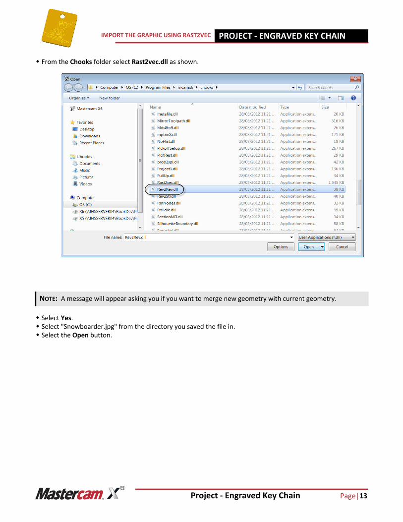
From the Chooks folder select Rast2vec.dll as shown.
Select Yes. Select "Snowboarder.jpg" from the directory you saved the file in. Select the Open button.
NOTE: A message will appear asking you if you want to merge new geometry with current geometry.

Page |14 Project - Engraved Key Chain
IMPORT THE GRAPHIC USING RAST2VEC PROJECT - ENGRAVED KEY CHAIN1
4.1 Black and White conversion
The Rast2Vec converter requires that an image be black and white in order to convert it from bitmap to vector format. When the file that you select to convert contains colors or gray tones, the converter provides a utility for changing the image to monochrome, using the Black/White conversion dialog box.Make sure that in the Black and White conversion page, the Linear Black/White conversion is enabled and the Threshold slider is set as shown in Figure: 4.1.1.
Figure: 4.1.1
Select the OK button to continue.
The left-hand preview box shows the original image with its colors or gray tones. The right preview box shows the image that will result from using the selected color conversion method and settings.
Project - Engraved Key Chain Page|15
IMPORT THE GRAPHIC USING RAST2VEC PROJECT - ENGRAVED KEY CHAIN1
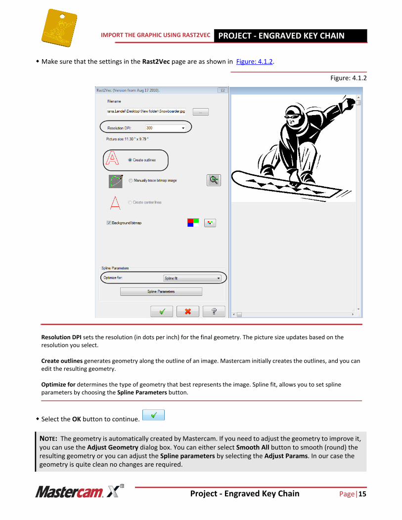
Make sure that the settings in the Rast2Vec page are as shown in Figure: 4.1.2.
Figure: 4.1.2
Select the OK button to continue.
NOTE: The geometry is automatically created by Mastercam. If you need to adjust the geometry to improve it, you can use the Adjust Geometry dialog box. You can either select Smooth All button to smooth (round) the resulting geometry or you can adjust the Spline parameters by selecting the Adjust Params. In our case the geometry is quite clean no changes are required.
Resolution DPI sets the resolution (in dots per inch) for the final geometry. The picture size updates based on the resolution you select.
Create outlines generates geometry along the outline of an image. Mastercam initially creates the outlines, and you can edit the resulting geometry.
Optimize for determines the type of geometry that best represents the image. Spline fit, allows you to set spline parameters by choosing the Spline Parameters button.

Page |16 Project - Engraved Key Chain
IMPORT THE GRAPHIC USING RAST2VEC PROJECT - ENGRAVED KEY CHAIN1
The preview of the geometry should look as shown.
Select the OK button to exit the Adjust Geometry dialog page as no changes are necessary.
Select the Yes button to exit Rast2vec as shown.

Project - Engraved Key Chain Page|17
SCALE THE GEOMETRY PROJECT - ENGRAVED KEY CHAIN1
The geometry should look as shown.
STEP 5: SCALE THE GEOMETRY
Use Xform Scale to scale down the geometry with a 0.125" scale factor.
Step Preview:

Page |18 Project - Engraved Key Chain
SCALE THE GEOMETRY PROJECT - ENGRAVED KEY CHAIN1
Xform
Scale. [Scale: select entities to scale]: Select Spline icon from the Quick Mask toolbar located to the right of the
graphics.
Press Enter to finish the selection. In the Scale dialog box, enable Move and enter as Factor 0.125. Leave the rest of the settings as shown in
Figure: 5.0.1.
Figure: 5.0.1
Select the OK button to exit from the Scale dialog box.
Select Fit icon to fit the geometry to the screen.
NOTE: All the entities should be selected.
NOTE: You should notice the color of your geometry has changed. The original entities are red and the mirrored entities (result) are magenta. This give you an opportunity, if needed, to quick select and modify these entities.

Project - Engraved Key Chain Page|19
BOUNDING BOX - CREATE A CENTER POINT PROJECT - ENGRAVED KEY CHAIN1
Select the Clear Color icon to reset the color to the system color. The geometry should look as shown.
STEP 6: BOUNDING BOX - CREATE A CENTER POINT
In this step you will use Bounding box command to create a point at the center of the graphic. This will help you to move the geometry in the center of the key chain.
Step Preview: