project 16st1: ac hydraulic pump/motorac hydraulic pump use concept of interfering waves to create...
TRANSCRIPT

Georgia Institute of Technology | Marquette University | Milwaukee School of Engineering | North Carolina A&T State University | Purdue University | University of California, Merced | University of Illinois, Urbana-Champaign | University of
Minnesota | Vanderbilt University
Generic Presentation Template for CCEFP
Update this text in the Slide Master
Mengtang Li, Graduate Student, Vanderbilt UniversityRyan Foss, Graduate Student, University of Minnesota
Prof. Eric Barth, Prof. James Van de Ven, Prof. Kim Stelson
Project 16ST1: AC Hydraulic Pump/Motor

AC Hydraulic Pump
Use concept of interfering waves to create variable displacement pump.
2 pistons in mutual chamberwith one of the pistons being adjustable in real-time.
Piston 1
Piston 2 (phase adjusting)
Combined Waveform
Daniel A. Russell, PSU
Different Net Displacements Using Interfering Waves (0 to 180 deg)
Piston Stroke
𝑓 =1 + cos𝜑
2
Fractional Displacement:

AC Hydraulic Pump
Phase Shift = 𝟎°, Fractional Displacement = 1
Displacements from each piston is added (doubled).

AC Hydraulic Pump
Phase Shift = 𝟏𝟖𝟎°, Fractional Displacement = 0
Fluid is shuttled back and fourth (cancelled).

AC Hydraulic Pump
Phase Shift = 𝟗𝟎°, Fractional Displacement = 70.83%
The combined displacement is continuously variable.

AC Hydraulic Pump Benefits
• Mount Multiple Pumps on Common Shaft
– Axially Short
– Through Shaft
Source: http://http://www.boschrexroth.com/

Research Plan
Tasks:
1. Develop dynamic pump model
– Focus on AC hydraulics dynamics
2. Parameter study
3. Design prototype pump
– Utilize off-the-shelf components
4. Fabricate pump and characterize
– Efficiency map
5. Design for motoring
6. Demonstrate displacement control
– Single actuator
Time (months)
6 months
3 months
4 months
4 months
6 months
3 months

Dynamic Model of AC Pump
• Model captures• Compressibility
• function of entrained air and pressure• Viscous effects• Check valves dynamics• Slider-crank kinematics• Input motor dynamics
• Modeled Created in Simulink
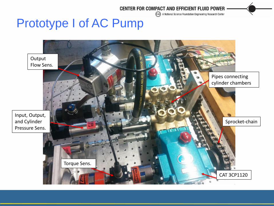
Prototype I of AC Pump
Sprocket-chain
CAT 3CP1120
Pipes connecting cylinder chambers
Torque Sens.
Input, Output, and Cylinder Pressure Sens.
Output Flow Sens.

• 2 CAT 3CP1120 Pumps.• Drill holes and connect corresponding
cylinder chamber.• Connect crankshafts via sprocket and
chain transmission.
Prototype I of AC Pump

AC Hydraulic Pump Prototype
• Goals of First Prototype:
– Prove concept of wave interference for displacement control.
– Validate mathematical model for design purposes.
– Compare performance of pump against other variable displacement pumps.
– Do parameter optimization.

Experiment for AC Pump
• Goal is to calculate efficiency by measuring torque, flow, and pressure.
• Ran tests for every possible phase angle (dictated by teeth of sprocket):
phase = [2,21,45,69,93,117,141,165]
• 4 different speeds:
rpm = [250,500,750,1000]

Model Validation - Pressure
𝜙 = 2𝑜, 250 rpmPressure in cylinder vs Time
𝜙 = 2𝑜, 250 rpmPV Curve of cylinder

𝜙 = 165𝑜, 250 rpmPressure in cylinder vs Time
𝜙 = 165𝑜, 250 rpmPV Curve of cylinder
Model Validation - Pressure

Model Validation - Torque
𝜙 = 2𝑜
250rpm1000psi
𝜙 = 165𝑜
250rpm1000psi

Model Validation – Flow Rate

Model Validation – Energy
*A constant 25 lbin torque is added to compensate the sprocket/chain torque.

Experiment Efficiency Result
• Efficiency curves role off due to constant friction (mechanical) and compressibility (volumetric). Fluid still compresses because pressure is maintained at high phase angles/low displacements.

Experiment Efficiency Result

Conclusion
1. Simulation model is built and is been validating now.
2. Prototype 1 is built and is been testing.
3. Baseline experiments are done for efficiency comparison.
4. Next step is to explore the parameter space and to optimize the design.
• Mengtang Li, [email protected]
• Ryan Foss, [email protected]

Calculating Efficiency• Total Efficiency:
𝜂𝑡𝑜𝑡 = 𝜂𝑇𝜂𝑉
• Volumetric Efficiency (compressibility, leakage):
𝜂𝑉 =2𝜋𝑄𝐷𝐷𝜔
𝑄𝐷 = Discharge/output flow, m^3/s𝐷 = Pump displacement per rev, m^3/rev𝜔 = Pump rotation speed, rad/sec
• Mechanical Efficiency (friction in fluid, joints, and seals):
𝜂𝑇 =𝐷Δ𝑃
2𝜋𝑇
Δ𝑃 = Difference between outlet and inlet pres, Pa𝐷 = Pump displacement per rev, m^3/rev𝑇 = Input torque, Nm
• Effective Displacement, 𝐷 :
𝑉1 =−𝑠𝐴
2cos 𝜃 +
𝑠𝐴
2
𝑉2 =−𝑠𝐴
2cos 𝜃 − 𝜑 +
𝑠𝐴
2
𝐷 = 𝑉1 + 𝑉2 =2𝑠𝐴
21 + cos(𝜑)
Note: pump’s for this test are crank-sliders that do not have perfect sinusoid motion, but pretty close.
𝜑