progressive collapse, methods of prevention · progressive collapse is a consistent destruction of...
TRANSCRIPT

Saimaa University of Applied Sciences The Faculty of Technology, Lappeenranta Double Degree Programme in Civil Engineering and Construction
Anastasia Vasilieva
PROGRESSIVE COLLAPSE, METHODS OF
PREVENTION
Bachelor’s Thesis 2013

2
CONTENTS
ABSTRACT ....................................................................................... 4
1 INTRODUCTION ............................................................................ 5
2 NOTION OF PROGRESSIVE COLLAPSE ..................................... 6
2.1 Progressive collapse ................................................................................... 6
2.2 Types of progressive collapse ..................................................................... 7
2.2.1 Pancake-type collapse ............................................................................. 8
2.2.2 Zipper-type collapse ............................................................................... 10
2.2.3 Domino-type collapse ............................................................................. 12
2.2.4 Instability-type collapse .......................................................................... 14
2.2.5 Section-type collapse ............................................................................. 16
2.3 Construction requirements ........................................................................ 16
2.4 Loads and recommendations for calculation ............................................. 21
2.5 Modern methods and approaches ............................................................. 23
2.5.1 Indirect method ....................................................................................... 23
2.5.1.1 Tie requirements for reinforced concrete structures ............................ 24
2.5.1.2 Tie requirements for precast concrete structures ................................ 25
2.5.2 Direct method ......................................................................................... 26
2.5.2.1 Specific local resistance ...................................................................... 27
2.5.2.2 Alternative path method ....................................................................... 28
2.6 Examples of collapsed buildings ............................................................... 30
3 METHOD OF CALCULATION ...................................................... 40
3.1 Design loads and resistance of materials. Assumptions for the calculation
........................................................................................................................ 40
3.2 Conditions ................................................................................................. 41
3.3 Calculation of the structures against progressive collapse ........................ 41
3.4 Sequence of calculation ............................................................................ 44
4 CALCULATION ............................................................................ 52
4.1 General information about the building ...................................................... 52
4.2 Structures .................................................................................................. 52
4.3 Process of calculation ................................................................................ 53

3
4.3.1 Attempt 1 ................................................................................................ 55
4.3.2 Attempt 2 ................................................................................................ 60
4.3.3 Attempt 3 ................................................................................................ 65
4.3.4 Attempt 4 ................................................................................................ 69
4.3.5 Attempt 5 ................................................................................................ 74
4.4 Conclusions ............................................................................................... 80
5 SUMMARY ................................................................................... 81
5.1 Definition ................................................................................................... 81
5.2 Design methods ........................................................................................ 82
5.3 Calculation part ......................................................................................... 82
5.4 Norms and standards ................................................................................ 83
LIST OF SYMBOLS ......................................................................... 84
FIGURES ........................................................................................ 85
TABLES ........................................................................................... 86
REFERENCES ................................................................................ 87
APPENDICES
Appendix 1 Example of calculation of the structure
Appendix 2 Example of calculation of the structure
4
ABSTRACT
Anastasia Vasilieva Progressive collapse, methods of prevention, pages. 86, appendices 2 Saimaa University of Applied Sciences, Lappeenranta Technology, Double Degree Programme in Civil and Construction Engineering Bachelor’s Thesis 2013 Instructor: Mr Petri Himmi (Saimaa University of Applied Sciences), Mr Pekka Narinen, Mr Johan Rosqvist (Finnmap Consulting Oy)
The purpose of the study was to describe the process of progressive collapse and to find more methods and approaches to design the structure for preventing from this kind of failure. And the last aim was to find Russian norms and standards and make calculations on progressive collapse of the trade center, according to them. In this way the work was commissioned by Finnmap Consulting Oy.
The thesis should be interesting to design engineers working with designing the large-span structures of public use like trade centers, stadiums or sport complexes, which are going to be built in Russia.
In the theoretical part of the project the main issue was to reveal and describe the term and the types of the progressive collapse, then to find out the reasons, appearance and effects from this event. Also the theoretical part includes a discussion of practical means for reducing risk of this collapse and shows the design methods and recommendations which are used to enhance a buildings resistance to progressive collapse. All information was gathered from Russian norms and recommendation for designing, also magazine articles, several scientific books and the Internet were used.
The analysis part of the thesis contains the general information about calculation process of the structure against progressive collapse according to Russian norms (recommendations). Also all formulas and dates which are needed in calculation were described.
The main part consists of the description of the building which were calculated and of course the calculations itself. All attempts and sequence of the calculation are shown and described. Then the analysis and conclusions about progressive collapse and calculations process was made.
As a result, this project described and disclosed a process of progressive collapse. Finally the calculation process for preventing structure from progressive collapse was made. And further these calculations will be used for other projects as an example.
Keywords: Progressive collapse, calculations, description, prevention.
5
1 INTRODUCTION
The client of the thesis is Finnmap Consulting Oy, which is part of Sweko. Finnmap
Consulting Oy is a fast-growing construction company which specializes in
engineering and consultancy, which makes a lot of projects abroad. Nowadays this
company makes more and more projects in Russia, which has very wide
construction market but compared with the European market less developed. So
working at this market Finnmap Consulting Oy meets a lot of problems. One of
them is the generalization of the facts and materials about progressive collapse
and methods of calculating for preventing building from this kind of failure. The
calculation process is the most important part of this thesis, in which the company
is more interested.
The main purposes of this project are:
1) To describe the term and the types of progressive collapse
2) To find out the causes and effects of progressive collapse
3) To show the design methods for preventing progressive collapse
4) To introduce the calculations of preventing building from progressive collapse
and show all the steps of calculations with notes, charts.
The main problems lie on the part of the calculation. The first is that nowadays
there are no design norms and standards for designing structures of preventing the
progressive collapse in Russia. And the second is that the whole calculation
process will be made by hands, because all software complexes could not analyse
and see all cases of damages. That is why it is necessary for Finnmap Consulting
designers for the future project to know the whole calculation process, step by
step.
So this project will show and describe the main phases, the required norms and
codes and other references, programs for understanding the calculation process of
progressive collapse for the large-span structures.

6
2 NOTION OF PROGRESSIVE COLLAPSE
2.1 Progressive collapse
Such term as progressive collapse was appeared not so a long time ago. For the
first time engineers faced with this phenomenon in 1968 when the Ronan Point
apartment building was destroyed. The structure was a 22-storey with precast
concrete, bearing walls. A gas explosion in a corner on the 18th floor blew out the
exterior wall panel and failure of the corner bay of the building spread upward to
the roof structure and down till the ground level, but the entire building did not
suffer (More about this example will be shown in another part of the chapter). So
this event was like a thrust for further study of that type of collapse in Europe, USA
and Russia. After that the term progressive collapse has been used to describe the
propagate of an initial local failure in a manner like a chain reaction that causes to
partial or total collapse of the structure. The basic characteristic of the progressive
collapse that the end state of the destructions is disproportionately greater than the
failure that made the collapse. But what does the term progressive collapse mean?
According to the Russian norms it means:
Progressive collapse is a consistent destruction of the bearing structures of the
building (structure) due to the initial local damage to the individual carriers of
structural components and leading to the collapse of the entire building or
substantial part thereof (STO-008-02495342-2009, 2009, p.1).
As for the European codes:
Progressive collapse is the spread of local damage, from an initiating event, from
element to element resulting, eventually, in the collapse of an entire structure or a
disproportionately large part of it; also known as disproportionate collapse (Bruce
R. Ellingwood, 2007, p. 1).
As can be seen the different norms approach the progressive collapse in different
ways, but they have in common some limits for the extent of the damage. Typically
destruction in such a collapse would extend one structural part, 100 m2 of floor
area, or two stories. That kind of crash can be initiated by many causes, including

7
design and construction mistakes and load events that are over design dimensions
or are not taken into account. Such events would include abnormal loads not
usually considered in a project. The potential abnormal loads that can cause the
progressive collapse are categorized like that:
a. Pressure Loads
Internal gas explosions
Blast
Wind over pressure
Extreme values of environmental loads
b. Impact Loads
Aircraft impact
Vehicular collision
Earthquake
Overload due to occupant overuse
Storage of hazardous materials
2.2 Types of progressive collapse
Even though progressive collapse is managed in the design rules and norms as
one event it can be divided into several parts depending on the reason for the
progressivity. The reason that causes the progressive collapse depends on the
type of structure and the initiating event. Below five types of progressive collapse
will be described. The presented collapse modes are pancake, zipper, domino,
instability, and section-type destruction.
8
2.2.1 Pancake-type collapse
When the capacity of a member carrying vertical load is inadequate it can lead to
the collapse of an entire section of a structure, as shown in figure 2.1. The upper
part of the damaged structure starts to fall and accumulate kinetic energy. The
impact force due to the falling part of the structure commonly exceeds the design
load of the remaining structure. If the floor underneath is not able to resist the
impact, the collapse will continue one floor at a time (Starrosek, 2009, p. 12)
The steps of a pancake-type progressive collapse are:
Initial destruction of the construction element carrying vertical load
Changing of the structures potential energy to kinetic energy until the fall
Impact of the destroyed structure to the rest load bearing parts
Failure of the vertical load bearing part hit
Promotion of the failure in vertical direction

9
Figure 2.1. The stages of the pancake-type progressive collapse, which include (a) the initial failure of a column, (b) changing of the structures potential energy to kinetic energy, (c) reloading of the structure below the initial failure, (d) promotion of the failure (Räty Johan, 2010).

10
2.2.2 Zipper-type collapse
The loss of a single load bearing member redistributes the force to the other
members situated transverse to the failure direction, as shown in figure 2.2. If the
resistance of the remaining members is exceeded, due to the extra load or its
dynamic character, the failure will be increased. The phases of the zipper-type
mechanism are:
Initial failure of one or a few vertical load bearing members
Dynamic increase in loading to the remaining members due to the
redistributing of the loads
Concentration of forces in load-bearing elements that are similar in type and
function to and adjacent to or in the vicinity of the initially failing elements
due to the combined static and dynamic structural response to that failure
Overloading of the remaining members, loaded the most
Failure of the members situated in a transverse direction to the falling
elements (Starrosek, 2009, p.15).
Also for this kind of collapse, the failure of elements may be connected with any
local failure mode, which contains instability (buckling).

11
Figure 2.2. the stages of zipper-type progressive collapse, including (a) the initial failure of a column, (b) reloading of the nearest columns, (c) the progression of the failure (Räty Johan, 2010).

12
2.2.3 Domino-type collapse
The characteristic of a domino-type collapse is the initial overturning of one
element. Then the unexpectedly overturning of involved elements next to the first
damaged element of the structure. And if the elements which were impacted lose
their stability overturns the failure is progressing in the horizontal direction. The
phases of a domino-type collapse are:
Initial overturning of an element
The transformation of the structures potential energy to the kinetic energy
due to the turning
Impact of the turning element to the next load bearing part
Overturning of the load bearing part stroked
Leading in a progressive collapse in a horizontal direction
The height of the overturning element has to be bigger than the distance to the
next element or the elements have to be connected to each other with some
horizontal load transferring member, as shown in figure 2.3 (Starrosek, 2009, p.
16-17).

13
Figure 2.3. The stages of domino-type progressive collapse, including (a) the initial failure and loading of the columns staying next to it, (b) upheaval of the columns, (c) the promotion of the failure till the overturning (Räty Johan, 2010).

14
2.2.4 Instability-type collapse
If the initial failure occurs in a critical member stabilising the entire structure a
collapse due to instability can occur, as shown in figure 2.4. Instability type
collapse´s initial disruption is minor and critical due to its direction, as a lateral
impact load on bracings, or position, as in the corner of the member stabilizing the
structure. The instability-collapse often occurs in compressed members where the
initial disruption can for example lead to large deformation and then to collapse. If
the initial failure leads to a disproportional collapse immediately then the
progression of the collapse is problematic to define. The phases of an instability-
type collapse mechanism are:
Initial failure of a stabilising member
Failure of the member transfer stabilising force to the remaining members
Progressive collapse due to stability loss of the member’s loaded or
immediate collapse due to the stability loss of the entire structure
(Starrosek, 2009, p. 21).
Basically this type of collapse occurs when is done the additional stiffness and
brace of the structural component.

15
Figure 2.4. The stages of instability-type progressive collapse, including (a) the primary construction with a bracing truss, (b) the initial failure in the girder, (c) the loss of steadiness till the lost part of the truss then (d) the crash till instability. (Räty Johan, 2010).
16
2.2.5 Section-type collapse
In the section-type of collapse a beam under a bending moment or a bar under
axial tension is taken into account. When a part of the corresponding cross section
is cut, the inner forces transmitted by that part are redistributed into the remaining
cross section. The corresponding increase in stress at some locations can be the
destruction of further of cross sectional parts and a failure progression throughout
the whole cross section. A section-type collapse appears similar to a zipper-type
collapse. Actually, the same list of features applies when the terms “cross sections”
and “part of cross section” are substituted for the terms “structure” and “element”,
respectively (Joshi Digesh, Patel Paresh, 2010, p. 14). The main difference is that
a cross section is amorphous and homogeneous whereas, for example, a cable-
stayed bridge consists of discrete elements of possibly different properties.
2.3 Construction requirements
A good project comprises looking beyond the minimum construction requirements
in the norms or standards. The existence and positional effects of abnormal loads
and the possibility of progressive collapse should be directly reflected in codes and
norms and become one of the important part of the design process. Codes of
practice should be noted that taking into account the risk of progressive collapse is
a necessary part of design, regardless of whether the stimulating event is an
accidental or normal load, and that such effects should be placed on the total
structural safety point of view. At the general level, the need to address the
accidental loads and progressive collapse in the design of structures must be
considered in building norms and standards for the performance requirement which
appears in a normative document. Here are some of the European and Russian
standards and codes for planning buildings against progressive collapse: Eurocode
SFS-EN 1991-1-7, Eurocode SFS-EN 1992-1-1, STO-008-02495342-2009, MDS
20-2.2008. There should be some statement regarding the general scope of the
provisions and other specific factors that might indicate a need for considering
progressive collapse resistance in design. Finally, there should be loading criteria
for checking the ability of the structure to resist accidental loads. Generally, only

17
the principal load-bearing system would need to be considered in these safety
checks (Ellingwood Bruce R., 2007, p. 25).
Of course there are some general ways to improve the overall stability of the
structure and its ability to cover damaged areas. Structural systems should be
designed to be robust. Their work should not be susceptible to uncertainties in the
distribution or environmental loads or other effects which are not taken into
account. The layout of walls and columns should provide stability and decrease the
amount of walls that can be broken. Floor slabs should be made to adapt a change
of span directions if a support is lost and to pass load to other supports, possibly by
catenary action. Walls should be designed to cover the areas of damage through
beam or arch action. Low compression elements and fragile details should be
avoided in critical points of potential alternate load paths, as should details that
make yielding in restricted zones.
For decreasing the probability of occurrence of progressive collapse in Russian
norms the following things are recommended. The first is that the mark of concrete
and reinforcement of structural elements should be appointed the highest of
comparing the results of calculations for the conditions of normal use of the
building. Then for reinforcing structural members particular attention should be paid
to the reliability of the anchorage reinforcement, especially at the intersection of
structural elements. The length of overlap and anchorage of reinforcing bars
should be increased by 20%. Also the longitudinal reinforcement of structural
elements must be continuous. Cross-sectional area of longitudinal reinforcement
(separate the lower and upper separately) slabs beamless floors joists and beams
should be not less than s,min = 0,2 % cross-sectional area element. And
longitudinal reinforcement of vertical bearing structural elements must accept the
tensile force of at least 10 kN per square meter of the loading area structural
member (STO-008-02495342-2009, p. 5-6).
Also to diminish the risk of continues collapse in the event of loss of structural
elements; the next structural features should be included in the project. Together

18
they form robust structures of restricting the spread of damage due to an initiating
event.
Redundancy: The incorporation of redundant load paths in the vertical load
carrying system helps to ensure that alternate load paths are available in the
event of local failure of structural elements.
Ties: The loss of a major structural element typically results in load
redistributions and member deflections. These processes require the transfer of
loads throughout the structure (vertically and horizontally) through load paths.
The ability of a structure to re-distribute or transfer loads along these load paths
is based in large part on the interconnectivity between adjacent members. This
is often called “tying a building together” by using an integrated system of ties in
three directions along the principal lines of structural framing. Figure 2.5
illustrates the different types of ties that are typically incorporated to provide
structural integrity to a building.
Figure 2.5. Different types of ties incorporated to provide structural integrity (Ellingwood Bruce R., 2007)

19
Ductility: In a catastrophic event, members and their connections may have to
maintain their strength through large deformations (deflections and rotations)
and load redistributions associated with the loss of key structural elements. For
reinforced concrete and reinforced masonry structures, ductility is achieved by
providing sufficient confinement of reinforcing steel, providing continuity in
reinforcement through adequate lap splices or mechanical couplers,
maintaining overall structural stability, and creating connections between
elements that exceed the strength and toughness of the base members.
Adequate shear strength: Structural elements in vulnerable locations, such as
perimeter beams or slabs, should be designed to withstand shear load in
excess of that associated with the ultimate bending moment in the event of loss
of an element. Direct shear failure is a brittle mode of failure and should not be
the controlling failure mechanism. Shear capacity should always exceed
flexural capacity to encourage a ductile response. Typical two-way slabs
without beams must be capable of providing post-failure resistance in the
presence of punching shear failures and severe distress around the columns.
Capacity for resisting load reversals: The primary structural elements (columns,
girders, roof beams, and lateral load resisting system) and secondary structural
elements (floor beams and slabs) should be designed, using acceptable
techniques, to resist reversals in load direction at vulnerable locations
(Ellingwood Bruce R., 2007, p. 34-35).
In addition, the following measures are recommended to enhance the overall
robustness of the structure:
In frame structures, column spacing should be limited. Large column spacing
decreases the likelihood that the structure will be able to redistribute load in the
event of column failure.
The exterior bay is most vulnerable to damage, particularly for buildings that are
close to public streets. It is also less capable of redistributing loads in the event
of member loss, because two-way load distribution is not possible. It is
20
desirable to have a shallow bay adjacent to the building exterior to limit the
extent of damage.
Loss of a transfer girder or a column supporting a transfer girder can destabilize
a significant area of the building. Transfer girders at the building exterior often
occur to accommodate loading dock’s large entry spaces, increasing their
vulnerability to air-blast effects. It is highly desirable to avoid transfer girders or
add redundant transfer systems where transfer girders are required.
In bearing wall systems that rely primarily on interior cross-walls, interior
longitudinal walls should be spaced periodically to enhance stability and control
lateral progression of damage.
In bearing wall systems that rely on exterior walls, perpendicular walls or
substantial pilasters should be provided at a regular spacing to control the
amount of wall that is likely to be affected (Ellingwood Bruce R., 2007, p. 35-
36).
Approval of resistance to progressive collapse during the process of designing
show extra strength to connections and will result in connections between
elements that should not exist if one were made for gravity and nominal lateral
loads alone. Numerous connections will permit for more uniform, smooth load
redistribution and prevent sudden changes in strength and stiffness that the result
in load concentration, overstress and early failure, damages. For a concrete frame
structure, the next design options can be included to raise the resistance to
progressive collapse. The first is to use the moment resisting connections in beam-
column joints that will hold load changes where only simple, gravity load
connections are necessary for ordinary construction. The second is to use
continuous top and bottom reinforcing steel in beams and floor slabs to allow them
to cover further or make catenary action.
21
2.4 Loads and recommendations for calculation
Some recommendations from Russian norms (STO-008-02495342-2009
“Prevention progressive collapse of monolithic concrete constructions”) on how to
collect loads and make calculations are presented and described below.
1. Calculation of secondary structural systems to prevent progressive collapse
should be made on a special combination of loads, including normative values
of permanent and long-acting temporary loads, with a coefficient equal to the
combination of φ=1,0. As for the second structural system, it is a primary
structural system, modifying by exception of one vertical load bearing element
(columns, pilasters, wall area) within one floor. And the primary structural
system is a system which is accepted for the ordinary conditions of using the
building.
2. For the constant loads the dead loads of the concrete bearing constructions,
the weight of parts of the structures (floors, partitions, ceilings, hygiene
equipment and self-bearing walls and etc.) and the lateral pressure from the soil
and the road carpet and sidewalks should be classified.
3. To the time long-acting loads should be classified:
Reducing the load of people and equipment on Table 3 SNIP 2.01.07-85*
35% of the total normative load from transport;
50% of the total normative snow load.
4. All loads should be considered as a static with safety coefficient for load
ɣ n = 1,0.
5. The calculation of the secondary structural system for preventing the
progressive collapse should be made separate for each (one) local destruction.
It is allowed to make calculation only for the most dangerous event of
destructions which could be the systems with the sequentially vertical bearing
structure elements:
having the maximum load area
located at the edge of the overlap
located in the corner

22
and spread the results of this calculations to the next sites of the structure
system.
6. A starting scheme should be the settlement scheme which was accepted for the
calculation of the primary structural system for the normal condition of use and
transform it for the secondary system by excepting step by step vertical bearing
structural elements for the most dangerous events of destructions. Also it is
better to include to the work the construction elements which are not always
taken into account in the calculation of the primary structure system.
7. As one excepted vertical bearing structural element can be column (pylon) or
the place of intersection or abutting at some angle bearing walls. The overall
length of these parts of the walls measured from the place of intersection or
junction to the nearest doorway in every wall or the conjugation with the wall of
other direction but not up to 7 m.
8. Vertical construction elements should be calculated as rigidly squeezing at the
top level of foundations.
9. The static calculation of the secondary structural system should be made as
elastic system for certified software complex with taking into account the
geometrical and physical nonlinearity. Also a calculation of only geometrical
nonlinearity can be considered. During the calculation with geometrical
nonlinearity the rigidity of sections of structural elements should be taken into
account according to SP-52-101-2003 and with long-term loads and presence
or absence of cracks. During the calculations with geometrical nonlinearity
stiffness of sections of construction elements should be made like the
composition of module proportionality Epr and moment of inertia of concrete
sections Jb.
The module proportionality Epr should be taken:
in determining of the forces Epr = 0,6Eb for horizontal elements and
Epr = Eb for vertical elements;
in calculation of stability Epr = 0,4Eb for horizontal elements and
Epr = 0,6Eb for vertical elements

23
10. Calculation of the sections of construction elements should be made according
to the norms and the forces which were getting after static calculation should be
considered like live load.
11. After the calculation of both structural systems, the forces in construction
elements are determined, the resulting class of concrete and reinforcement
mark, nodes of their connections are assigned and the margin of stability is
installed but if it is not enough should be changed the dimension of elements or
changed the construction scheme (STO-008-02495342-2009, p.4-5).
2.5 Modern methods and approaches
Nowadays exist two approaches to ensure sustainability for progressive collapse,
they are the indirect method and the direct methods. The indirect method is a
prescriptive approach of granting the minimum level of links between different
structural components and little additional structural analysis is required by the
designer. Basically instead of calculations which show the effects of abnormal
loads on buildings, the constructor can use an implicit design method that includes
measures to improve the overall reliability of the structure. But the direct methods
are strongly dependent on the structural analysis, designer obviously considering
the ability of the structure to resist the influence of an abnormal event load.
2.5.1 Indirect method
Indirect method is a prescriptive approach that can be used to improve the overall
reliability of the structure during the process of design through provision of
minimum levels of strength, continuity and ductility. Thus the indirect method will
probably be the basic method used to increase the robustness of the building.
Indirect design approach has the explicit advantage as the easiest way to use and
provide uniformity of compliance in all projects. Although this event is an
independent approach and does not rely on detailed calculations of the structural
response to an abnormal load, this leads to a continuous tied reinforcement for the
concrete frame structure in order to develop more of their potential when exposed
to abnormal loading conditions. Although the vertical load is not effectively resisting
horizontal ties, loads, which were originally supported by corrupted parts of the
24
structure will be redistributed to the intact structure elements. So the indirect
approach is for the regular layout design of buildings that do not contain significant
transfer mechanisms and structures and which do not correspond to higher
importance categories.
2.5.1.1 Tie requirements for reinforced concrete structures
In concrete constructions the reinforcement can be used to satisfy, in particular, the
requirements for internal connections, peripheral ties and column ties. Bars may be
considered anchored to another tie at right angles if the bars go beyond all the
other tie bars for the effective length of the fixing. Connections should be
adequately anchored, where essential changes in the construction or re-angles are
interrupted the continuity of the ties.
Internal ties at each floor and roof level should be in two perpendicular directions.
The ties should be effectively continuous throughout their length and should be
anchored to the peripheral ties at each end. The ties may be spread evenly in the
slabs or may be grouped at or in beams, walls or other appropriate structural
elements. The ties should not be spaced greater than 150 % of the spacing of the
columns, frames or walls supporting any two adjacent floor spans in the direction of
the tie. In walls, the ties should be relatively close to the top or bottom of the floor
slabs. These ties should be capable of resisting a prescribed tensile force in each
direction (Ellingwood Bruce R., 2007, p. 40).
Effective continuous peripheral tie should be provided at each floor and roof level,
able to resist the prescribed tensile force is relatively close to the edge of the
building or inside the perimeter walls. Every external column and the load-bearing
external walls should be anchored or tied horizontally into the structure at each
floor or roof level with a tie able to develop the prescribed force that should be a
percentage of the overall design of finite vertical load carried by the column or wall
at this level. If the connection is located inside the external wall, a positive
connection must be secured between the inner and peripheral ties. Corner
columns should be tied into the structure at each floor and roof level in each of two
perpendicular directions with ties each capable of developing a prescribed force,

25
which should be a percentage of the total design ultimate vertical load carried by
the column or wall at that level (Ellingwood Bruce R., 2007, p. 41). All columns and
walls supporting vertical load should be tied continuously from the lowest to the
highest level. The tie should be able to withstand the largest vertical load which is
taken into account, the resulting column or wall of any story due to normal design
load combinations. Where the column or wall at the lowest level element is not
supported, except for the foundation, the overall testing of the structural integrity
must be done to ensure that there is no inherent structural weakness of the
scheme and that adequate means exist to transmit the dead, live and wind loads
safely from the highest supported level to the basics.
2.5.1.2 Tie requirements for precast concrete structures
In precast and composite structures, the ties should be effectively continuous. The
ties should be anchored qualitative such that the anchorage is able to bearing the
dead weight of the element to that part of the construction which has the ties. For
reinforced bearing the continuity of the bearing is dependent on the floor of
reinforcement and the restriction against loss of bearing through motion. The net
bearing width should be based on the design final support reaction per member,
the effective bearing length, and the design final bearing stress. A bar or tendon in
precast elements should be overlapping with a bar in cast-in-place connecting
concrete bounded on two opposite sides by rough faces of the same precast
member alternatively, a bar or tendon in a precast concrete member should be
lapped with a bar in cast-in-place topping or connecting concrete anchored to the
precast member by enclosing links. The ultimate resistance of the links should not
be less than the ultimate tension in the tie. Bars projecting from the ends of the
precast members may be joined by lapping of bars, reinforcement grouted into
apertures, overlapping reinforcement loops, sleeving, threading of reinforcement or
welding of bars. Alternatively, bars may be lapped with cast-in-place topping or
connecting concrete to form a continuous reinforcement with projecting links from
the support of the precast floor or roof members to anchor such support to the
topping or connecting concrete (Ellingwood Bruce R., 2007, p. 41).
26
Transfer of compression joints should be made to withstand all the forces and
moments implicit in the analysis of the structure as general and making the
individual elements must be connected. Joints transfer to shear plane can be
assumed effective if the connection is grouted with appropriate concrete and
mortar and does not need moderation if the design ultimate shear force the joint
not exceeding rated capacity. Joints transmitting shear under compression in all
design conditions may be effective if the joint is filled with the sides or the ends of
the panels forming the joint have a rough-cast trim and the development of the final
shear stress is not exceeding the rated capacity. The division of the units normal to
the joints should be avoided either steel ties across the ends of the joint or by the
compressive force normal to the joint under all loading conditions. Joints
transmitting shear can be expected effective if reinforcement is secured to resist
the whole shear force due to design ultimate loads. The shear force should be
limited by shear friction across the joint.
2.5.2 Direct method
In the direct design methods, resistance from progressive collapse is made by
increasing the strength of the main construction elements to avoid the failure under
accepted abnormal loads or making the structure so that it can cover the local
failure area. But on the other hand, the direct design methods need more
complicated analyses compared with the ordinary gravity and lateral load analyses
used in regular design. So this part of the chapter will discuss the two approaches
for preventing the progressive collapse, they are: the alternate path method
(method that allows local failure to occur, but seeks to provide alternate load paths
so that the damage is absorbed and major collapse is averted) and the specific
local resistance method (method that seeks to provide sufficient strength to resist
failure from accidents or misuse).

27
2.5.2.1 Specific local resistance
The method of specific local resistance is internal threat specific design approach
and the design threats may be in the form of explosive, impact or fire loading.
According to this method, some structural key elements are locally hardened and
detailed to resist specific a thread. As for the key element, it is a structural member
that meets two conditions. The first is not larger than the structural part assumed to
initially fail at a time. And the second, its failure, if no countermeasures are taken,
results in unacceptable total damage (Starossek, 2009, p. 52). Also the most
important elements can be made to full the resistance without failing the
connections or supporting members framing into it. This balanced approach treats
the load path structure in designing full strength available for key members. The
specific local resistance method allows increasing the strength of key elements, for
example exterior columns, to withstand any threat that can destroy two adjacent
columns.
To enhance the overall performance of the structure, the specific local resistance
method should be added with redundant ductile detailing. For concrete structures,
this detailing involves the use of continuous bottom reinforcement over supports,
restriction at joints, adequate ties to allow for load transfer, peripheral ties at the
spandrels, internal ties through floor slabs and beams, horizontal ties to columns
and walls, vertical ties along the perimeter structure and tension ties for precast
concrete construction (Ellingwood Bruce R., 2007, p. 48).
The specific local resistance direct design approach may improve the resistance of
a structure to a larger threat than can be achieved by other design methods. A
rational design approach that could ensure the general protection against
progressive collapse may be a combination of the indirect design method for
prescribing necessary details and the specific local resistance method to
strengthen vulnerable structural members. This approach can be used to increase
the resistance of the structure to events that would otherwise damage two or more
columns and invalidate the alternate load path design approaches based on a
single-element removal.

28
2.5.2.2 Alternative path method
Alternative path method is a method of transferring the forces through the loss of a
load-bearing element. This approach does not determine threats or the reason of
damaged condition; it restricts the acceptability of the abnormal loading conditions
that would cause the provided level of damage. The advantage of this method is
that it supports structural systems with ductility, continuity and energy consuming
properties that are suitable in preventing the progressive collapse. This approach
would certainly discourage the use of a large transfer girder that prevents a
significant number of the columns from extending to the ground floor. This method
is also consistent with the seismic design approach used in many building codes
throughout the world. The seismic norms promote regular structures that are well
tied together. They also require ductile details so that plastic rotations can take
place (Bruce R. Ellingwood, 2007, p. 50).
Figure 2.6. Alternative path method, example of removal column (www.sideplate.com).

29
What is more, several theories, including beam, catenary and other actions, can be
used for calculating distribution of loading after the loss of the column or another
bearing element of the construction. The beam action needs moment resistance
from the horizontal member when the catenary action is based on the axial force of
the membrane. If the capacity of the beam action is exceeded the catenary can be
used after a larger deflection assuming that the connection is still able to carry axial
forces as shown in Figure 2.7. Certain amounts of continuity of bottom and top
reinforcement have to be provided to ensure that the building concrete parts do not
fall down. Top reinforcement can be torn out from the concrete on top of a falling
column and therefore continuity of bottom reinforcement on top of supports is
required (Räty Johan, 2010, p.43-44).
Figure 2.7. The balance condition for beam and catenary action (Räty Johan, 2010)
Beam action
The theory of beam action is based on the assumptions that the horizontal
members resist deflection. This needs a sufficient moment resistance of the
member and therefore cannot be used in the case where beams or slabs have
hinge connections at the lost support. In the accidental stage when the loading or
span width is increased the linear moment resistance of the member can be
exceeded and plastic hinges are deformed. (Räty Johan, 2010, p. 44)
Catenary action
The theory of catenary action assumes that vertical load is carried by the plastic
moment and the axial force of a horizontal member after the deflection of the
member has become significant. Due to the large deflection the member will
stretch which leads to plastic stretching and bending. The axial force decreases the
30
plastic moment capacity of the member which has to be taken into account. The
catenary action can also be used for members without any moment capacity and
therefore also for beams without moment resistant connections (Räty Johan, 2010,
p. 45).
2.6 Examples of collapsed buildings
This part will show the examples of the buildings where the first kind of this failure
occurred. Also the causes of this type of destruction will be explained and
analyzed, and what actions have been taken to prevent this type of the collapse in
the future.
The first instance is a failure of an entire corner of a 22-story block of flats called
Ronan Point in east part of London (the United Kingdom). The structure of this
multi-story building is the large precast concrete panels which were adopted in the
United Kingdom in the end of the 1950s. This type of structure was accepted to
achieve faster construction of new dwellings after the losses from the Second
World War. The Ronan Point scheme was founded on a Danish system, licensed
to a British construction company with its structural design secured by a subsidiary
firm. In essence this system was using in construction of new building the precast
concrete elements. The main advantages for this method of the construction were
rather short time period of the erection, minimum construction work and workers. In
fact the structure was rectangular on plan. The base of the dwelling was the
monolithic concrete foundation slab. Every wall, intermediate floors and stairways
were precast. All precast loadbearing walls which relied mainly on friction to hold
them in place and the only load action considered in the design was wind load.
Tooth-edged floor panels were fitted into slotted wall panels, and the joints were
then bolted together to lock the panels together, providing continuity and mutual
interaction. Connections were filled with dry-pack mortar for further security (Levy
and Salvadori 1992, p.79).

31
After examination of the main structures of the building we can move on to the
reasons and description of the progressive collapse. At about 5:45 am on Thursday
16 May 1968 a tenant on the 18th floor of the 22-story Ronan Point apartment
tower struck a match in her kitchen. The flame aroused a gas explosion from a gas
leak. Then the bang broke down a non-bearing wall panel and at the same time
blew out three flank loadbearing storey-height wall panels in the apartment. These
external loadbearing walls performed as the single support of the 19th floor. That is
why the loss of that structure made the panels above unsupported. This led to the
chain reaction where the 19th floor collapsed, then went down the 20th floor and so
on propagating up to the roof structure. That process was called the first phase of
the progressive collapse. After the crash of four storeys on the 18th the second
phase of the progressive collapse was started. The sudden impact loading on the
18th level caused it to give way, smashing the 17th floor and progressed downward
until ground level was reached.
The collapse sheared off a portion of the living room of the southeast apartments,
leaving bedrooms intact, aside from floors 17 through 22 where the fatalities
occurred. Due to the time that the collapse happened, most of the tenants were still
sleeping in their bedrooms, considerably reducing the fatality rate (Delatte 2009, p.
101). Two figures are given below. The first shows the plan of the flat where the
accident started and what parts of the structure were crashed, and the second is
the Ronan Point building after collapse.

32
Figure 7.1. The plan of the flat at the 18th floor (failures.wikispaces.com)
Figure 2.9. Ronan Point after collapse (failures.wikispaces.com)

33
After the accident investigations were made about the cause of the collapse which
showed that the leak of the gas was not the only reason of the disaster. Because
the evidence suggests that the explosion was not large, the pressure was less than
68,9 kN/m2. Nevertheless, extensive testing suggested that a more pressure of
20,7 kN/m2 could have displaced the exterior walls of Ronan Point, a pressure less
than one-third that of the explosion (Levy and Salvadori 1992, p. 80). Also the
collapse of Ronan Point was due to its lack of structural redundancy. The structure
had no fail-safe and no alternative load paths for the upper floors when the level is
gone away. Public inquiry into the collapse displayed that the strong winds or the
effects of a fire could also have caused a progressive collapse. The building was
designed using building codes that were fifteen years old. These codes did not
take into account wind loads occurring at current building heights. Moreover this
kind of dwelling in Denmark was not intended for building over six stories and this
fact was not taken into account. The next reason was that the steel tie-plates
connecting the walls to the floor slabs were further evidence of negligence. All the
tie plates inspected showed that laborers failed to tighten the nuts of the
connecting studs. Figure 2.10 illustrates the connection as built, and the poor
workmanship that was uncovered. Figure 2.11 shows the right connections which
would be in that type of the building.
Figure 2.10. Exterior horizontal joint between floor slab and flank wall as built (failures.wikispaces.com)

34
Figure 2.11. Joint wall panel with a parapet (Shkinev A.N., 1984)
Thus after the inspection by the commission these aspects were taken. For the
future the structure would be adopting a robust and stable structural form. Also the
constructions would be provided with adequate stiffness and strength to resist
significant lateral loads, even when actual loading to be resisted is minimal. Then
all interaction between components would be ensured by connections or provision
of ties and after the end of the construction work quality control should be made.
Moreover building codes, regulations, and guidelines, as well as design methods
were revised accordingly throughout the world:
The United Kingdom amended their building regulations in 1970. Buildings
more than four stories in height were to be designed to resist progressive
collapse (Pearson and Delatte 2005, pp. 175).
The British government mandated guidelines that required fail-safe
mechanisms in large-panel system structures, steel bracing with floor-to-wall
connectors, and a minimum tensile strength of 20684 kN/m2 across the length
and width of roofs and floors (Delatte 2009, p. 104).
The Portland Cement Association and the Prestressed Concrete Institute
developed guidelines that required building elements be tied together (Delatte
2009).
Changes were also made to U.S. model codes, which required structural
systems remain stable, even after sustaining local damage (Pearson and
Delatte 2005, p. 175).

35
Unfortunately Ronan Point was not the last building with progressive collapse.
Another example of that kind of failure was the Alfred P. Murrah Federal Office
Building in Oklahoma City (the United States of America). But the cause in this
case was bomb explosion. The Alfred P. Murrah Federal Building was designed for
the GSA Public Buildings Service in the early 1970s. The project consisted of
several parts. The first and main part was a nine-storey office building then goes
two one-story ancillary wings, and a multilevel parking garage. The structural
system for the nine-story portion of the Murrah Building was an ordinary concrete
moment frame. The framing plan for the structure was composed of two 10,8 m
bays in north-south direction and ten 6,2 m bays in the east-west direction. Typical
floor-to-floor height for the building was 4,0 m for floors three through eight and
4,32 m for the ninth. Dropside system of a building was made of cast-in-place
concrete core / shear walls that were put up outside on the south side. Further to
shear walls in the south face of the nine-storey building was made of reinforced
concrete and glass spandrels curtain wall system. East and West elevate structure
also contained prefabricated spandrels, and a 3-inch (76,2 mm) granite stone
panels have replaced glass curtain walls. The north facade had a special
architectural feature that proved to be particularly vulnerable to the effects of the
explosion: To provide street access to the first floor, the second floor was held
back 3,1 m from the north building face and was supported by one-story wall
sections spaced 12,3 m over center. At the third floor, a large transfer beam,
supported by two-story-high columns spaced 12,3 m over center, carried the load
of the columns above it, spaced at the normal 6,2 m over center. From the third
floor to the roof, the north wall was glazed with a full-height window/wall system.
The first- and second-story windows were set back from the street. (Hammond,
1995). Two figures of the Alfred P. Murrah Federal Building before and after the
bomb explosion is presented below.

36
Figure 2.12, 2.13. The north facade of the building before and after collapse
(failures.wikispaces.com)
So on 19 April 1995 the handmade bomb contained in a rental truck which was
parked in front of the nine-story office building on N.W. Fifth Street, destroyed or
badly damaged three columns ( G16, G20, G24). The column G20 which was the
nearest to the detonation position was likely removed by the power of the explosion
which is the complete shattering of concrete. Columns G16 and G24 were found
not to be in close enough proximity to the detonation point to suffer from the power
of the blast. However, lateral loadings due to blast were applied to weak axis of
these columns. Loss of support from these columns led to failure of a transfer
girder. Failure of the transfer girder caused the collapse of columns supported by
the girder and floor areas supported by those columns. Below the process of blast
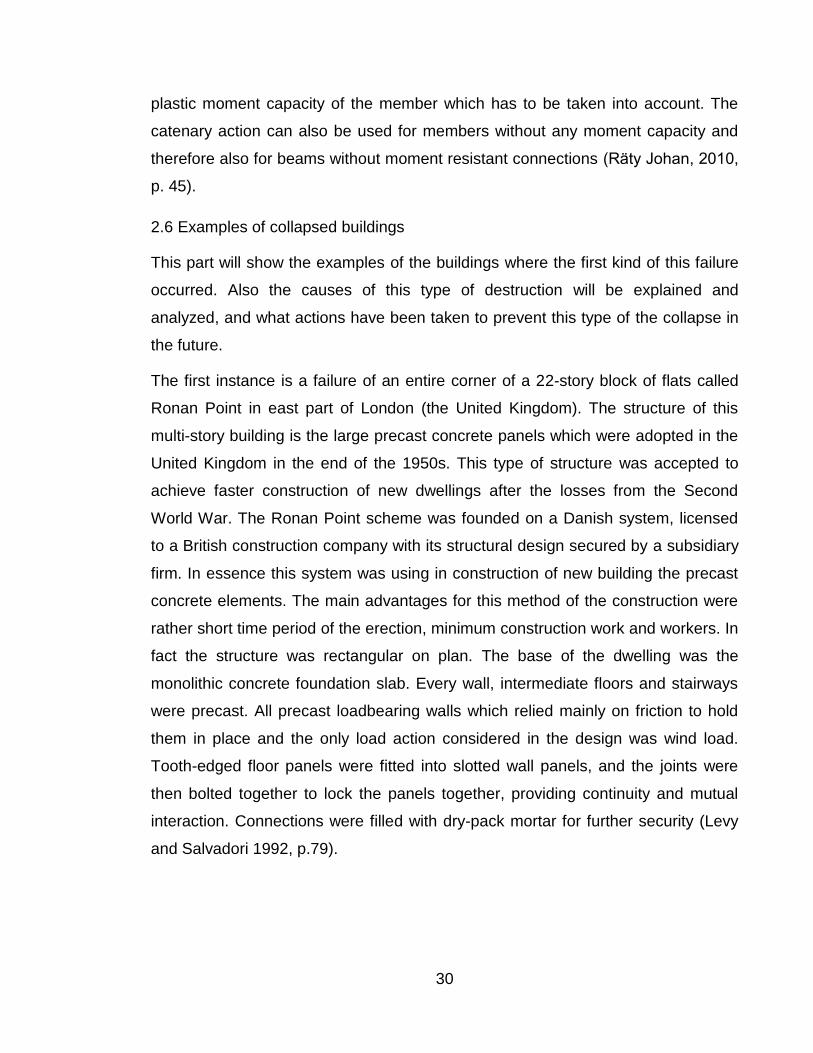
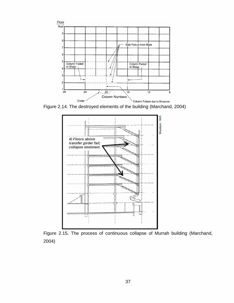
load propagation and progressive collapse is shown. Figure 2.14 illustrates the
damaged elements on the North facade. Figure 2.15 shows the numbered
sequence of the failure to the building columns, transfer girder and floors
(elimination of lateral support for the remaining columns). Meanwhile figure 2.16
presents the position of the damaged elements just before the final collapse.
37
Figure 2.14. The destroyed elements of the building (Marchand, 2004)
Figure 2.15. The process of continuous collapse of Murrah building (Marchand,
2004)

38
Figure 2.16. Pre-Collapse position of building elements in Murrah construction (Marchand, 2004)
The Murrah Building disaster clearly was a progressive collapse by all the
definitions of that term. Collapse of a large part of the building was deposited by
demolition of a small part of it (a few columns). The collapse also involved a clear
sequence or progression of events: column destruction; transfer girder failure;
collapse of structure above. After the accident a special commission (FEMA –
Federal Emergency Management Agency) was assembled to investigate the
causes of the incident. The investigation shows that the structure of the Murrah
Federal Building was complied with all the codes and provisions at the time for the
design and construction of an ordinary reinforced concrete frame structure (Corley,
1998, p.109). During the investigation several ideas were made to change
constructive scheme, which would a little bit reduce the effects of collapse. One of
them was to extend down the ground the smaller columns 6,2 m apart at the north
facade and the structure would have been designed to tolerate the loss of one of

39
them. Improved local resistance, within plausible limits, would not have prevented
destruction of the ground-floor column closest to the bomb. But improved ductility
and shear capacity of the columns (possibly through the use of the kind of
reinforcing steel details used in earthquake - prone regions), and better
interconnection and continuity throughout the building, could have prevented the
loss of any of the other large ground-floor columns, and could have limited the
collapse to a 18,5 m to 24,7 m width of structure from the ground to the roof — a
major disaster but much less than what actually happened. (Nair Shankar, 2004, p.
9). Below the recommendations that were considered after investigation are
introduced:
To create new norms and codes that would take into account measures to
calculate for progressive destruction.
To make better interconnection and continuity throughout the structure and
different reinforcing steel details in the columns.
Two-way floor slabs should be designed with alternate load paths.
Floor systems should be designed to develop full strength of reinforcement
Continuous bottom reinforcement in slabs along column lines
All columns in public areas to be designed for unbraced lengths of a
minimum of two stories
Outer bays redundantly designed to account for the loss of a ground floor
column (Hinman, 1997, p. 34)
In such a way these examples show how the destruction from the progressive
collapse is unexpected and destructive, if it has not been taken into account in the
design project. But due to these two disasters the engineering community started
to study and analyze this type of fracture. During a long period they were analyzing
this process, finding the ways and methods for preventing it. Also a lot of norms
and standards were published and were taken into account in the design of this
process of destruction and different kinds of programmes were created to calculate
progressive collapse.

40
3 METHOD OF CALCULATION
3.1 Design loads and resistance of materials. Assumptions for the calculation
Some prerequisites and assumptions for calculation were pointed earlier. In this
part they will be considered in detail and in relation to the calculated building.
Reinforced concrete buildings should be protected against progressive collapse in
the event of local failure of load-bearing structures as a result of accidental
emergencies. Survivability of buildings must be provided to verify by the
calculations and constructive measures which contribute to development of plastic
deformation in load-bearing structures under ultimate loads.
Calculation for the strength and survivability of the building should be made using
special combination of loads, including the impact of the local forces on the
structure, dead and long-acting live loads at the most dangerous case of local
failure. In frame buildings this role can be performed by destruction (remove) of
columns or columns adhering to them portions of the walls, located on one (any)
floor on the area of local failure. Local destruction may be located anywhere in a
building. Dead load is applied like dead weight of load-bearing reinforced concrete
structures, weight of building parts. Long-acting live loads include reduced load of
people and equipment, 35% of full normative loads of vehicles and 50 % of full
normative snow loads.
Normative values of dead and long-acting live loads are considered according to
current normative documents (or by the special task) with the coefficient of
combinations and safety factor .
Calculated strength and deformation characteristics of the materials are taken as
their normative values according to the current normative documents for design
reinforced concrete structures and steel constructions.
The values of the deformation and the width of the cracks in structures are not
regulated.

41
Spatial design model is used to calculate buildings against progressive collapse.
Such model can take into account elements which are non-load bearing under
normal conditions but in the case of progressive collapse those elements may take
emergency loads and actively participate in the redistribution of forces in the
elements of the structural system.
3.2 Conditions
Exceeding the applied step of columns can create the conditions for the loss of
stability in case of the progressive collapse. Here preventing the collapse will
require a significant increase in consumption of concrete and reinforcement and
complexity of the design of reinforcement and connections.
Checking of stability for resistance to progressive collapse is based on comparing
the efforts of individual structural elements derived from static analysis with critical
efforts that can be perceived by these elements. Stability against progressive
collapse of the building is provided, if for any elements the following condition is
observed (1):
(1)
where
F – effort in a structural elements,
S – calculated bearing capacity.
In constructions, where strength requirements are not met, amount of
reinforcement and cross-section of elements must be enhanced.
3.3 Calculation of the structures against progressive collapse
1. For calculation of the structures it is recommended to use the three-dimensional
model. The model takes into account the elements which in normal service
conditions are non-load bearing in local deformations and effects, but actively
involved in the redistribution of forces in elements of the structural system. The
calculation model of the building should provide the removal (destruction) of the
individual vertical structural elements. Removal of one or more elements of the

42
constructive scheme changes the character of the work of the elements, which are
adjacent to the place of damage or hovering over it. This is necessary to consider
in the appointment of the stiffness characteristics of the elements and their ties
(joints). Calculation model of the building must be calculated separately with taking
into account each (one) of the local destruction.
2. When determining the limit forces in the elements (their carrying capacity)
should be taken into account:
a. The part of the long acting live loads which is taken from the structural scheme
for the design scheme without local destructions.
b. The part of the short acting live loads is taken like the difference of forces
received from calculation of the structural scheme with the removal (destruction) of
the bearing elements.
3. In case when is provided the plastic work of the structural scheme in limit state,
the verification of resistance to progressive collapse elements situated above local
destruction, it is recommended to make by kinematic theory method of limit
equilibrium, which gives the most economical solution. In this case the calculation
of the building at each selected scheme is performed by the following procedure:
a. The most probable ways of progressive collapse of the structure are determined,
which lost their support ( so it means to make the ways of destruction and
determine all breakable connections, including the formed plastic hinges and find
possible generalized displacements (ωi) in the direction of efforts in these joints)
b. For each of the selected mechanisms of progressive collapse the limit efforts are
determined, which can be taken by all sections of plastic destroyed elements and
connections (Si) and also the plastic hinges. When the results of the external
forces (Gi) are found, which acted to the individual links of the structure, so to the
non-destructive individual elements or parts of them and move them in the
direction of their actions (ui)
c. Determine the works of the internal forces (W) and external loads (U) to the
possible displacements of the mechanism
W = ∑Si,wi; U = ∑Giui (2)
and check the equilibrium condition

43
W ≥ U. (3)
In assessing the possibility of simultaneous structural collapse of all floors
equilibrium condition (3) is replaced by
Wf ≥ Uf, (4)
Where Wf and Uf is the work of internal and external forces for the movement of the
one floor structure element, the floors are separated by the bottom surface of slab,
which belongs to the floor, located above the floor.
d. For each is selected a local destruction it is necessary to consider all of the
following mechanisms of progressive collapse:
The first type of progressive collapse is characterized by simultaneous
translational displacement down of all vertical structures (or parts thereof), located
on a place of local destruction.
The second type of progressive collapse is characterized by simultaneous
rotation of each structural part of the building, located over local destruction area,
around its center of rotation. This kind of movement needs the destruction of the
connections between failure and non failure constructions, and the connection
destruction by the shear of vertical elements with overlapping.
The third type of progressive collapse is not only the collapse of the overlap,
which is located directly above the beaten out vertical structure and initially
supported on it.
The fourth type includes movement of structures of only one floor directly above
knocked out vertical element. In this case starts the separation of the vertical
structures from the overlap, which is located above them. If any design scheme
condition (3) or (4) is not satisfied, it is necessary by the strengthening of structural
elements or other actions to achieve its fulfillment.
e. In some cases it is more comfortable to consider the work of the slab above the
removed column (wall) with large deflections as the elements of the hanging
system, or with the membrane effect.

44
f. In bearing columns, which will not be situated above the local destruction its
influence leads to increase stresses. It is necessary to make the calculation of the
strength of these elements.
g. Every overlap of the building should be calculated for the perception of the
weight of the overlying floor area of overlap (permanent and long-term dynamic
load factor kf = 1,5).
According to the height of the building the local destructions can be at any floor of
the building. That is why if at the building there are several similar floors, it is better
to check the most dangerous or all floors.
3.4 Sequence of calculation
In this part the sequence of calculation and explanation of applied values and
factors are shown.
1. To ensure work of construction in emergency situation, it is needed to perform
condition of stability against progressive collapse in case of removal a column
(formula 1).
It is allowed to delete any load-bearing vertical element and check the load-bearing
capacity of the rest structure.
2. The most dangerous load-bearing vertical element is selected (for example the
most loaded column);

45
3. Conventional removal of chosen element (figure 3.1). When any load-bearing
element is deleted, loads are increased for the other elements. Because of
enhanced loads, plastic hinge in the middle of the span appears, that can lead to
significant deformation. But construction can withstand these increased loads
because part of these loads comes to membrane structures.
Figure 3.1. The shape of the yield lines when a column is notionally removed
(Aalto, 2010)
4. Finding the external load for the beam and slab structure with load factors (for
live and dead loads and coefficient on responsibility equal to 1,0).
4.1 the average characteristic own weight for the slab and beam:
(5)
– own weight of slab and beam structure (dead load), ;
46
– thickness of slab, ;
– density of concrete, ;
– width of beam, ;
– height of beam, ;
– span, .
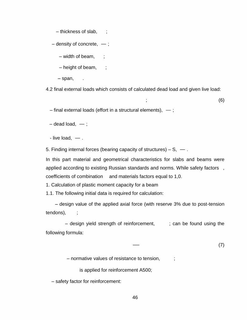
4.2 final external loads which consists of calculated dead load and given live load:
; (6)
– final external loads (effort in a structural elements), ;
– dead load, ;
- live load, .
5. Finding internal forces (bearing capacity of structures) – S, .
In this part material and geometrical characteristics for slabs and beams were
applied according to existing Russian standards and norms. While safety factors ,
coefficients of combination and materials factors equal to 1,0.
1. Calculation of plastic moment capacity for a beam
1.1. The following initial data is required for calculation:
– design value of the applied axial force (with reserve 3% due to post-tension
tendons), ;
– design yield strength of reinforcement, ; can be found using the
following formula:
(7)
– normative values of resistance to tension, ;
is applied for reinforcement A500;
– safety factor for reinforcement:
47
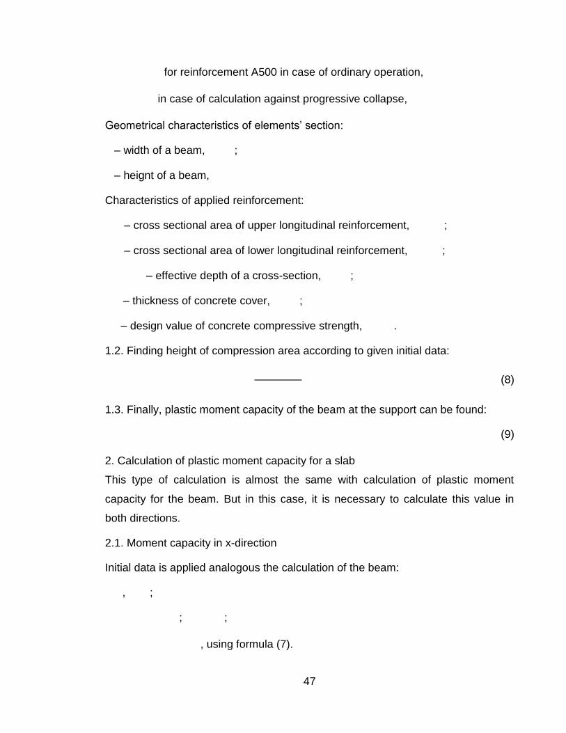
for reinforcement A500 in case of ordinary operation,
in case of calculation against progressive collapse,
Geometrical characteristics of elements’ section:
– width of a beam, ;
– heignt of a beam,
Characteristics of applied reinforcement:
– cross sectional area of upper longitudinal reinforcement, ;
– cross sectional area of lower longitudinal reinforcement, ;
– effective depth of a cross-section, ;
– thickness of concrete cover, ;
– design value of concrete compressive strength, .
1.2. Finding height of compression area according to given initial data:
(8)
1.3. Finally, plastic moment capacity of the beam at the support can be found:
(9)
2. Calculation of plastic moment capacity for a slab
This type of calculation is almost the same with calculation of plastic moment
capacity for the beam. But in this case, it is necessary to calculate this value in
both directions.
2.1. Moment capacity in x-direction
Initial data is applied analogous the calculation of the beam:
, ;
; ;
, using formula (7).

48
Geometrical characteristics of elements’ section:
– design strip of a slab, . Calculation of moment capacity is made for design
strip of the slab equals to 1000 mm;
– thickness of a slab,
Characteristics of applied reinforcement:
– cross sectional area of ongitudinal reinforcement in x-direction, ;
– effective depth of a cross-section, ;
Height of compression area is found according to formula (10):
(10)
(11)
Formula (11) is used to find the relative height of compression area (when the
diagram of stress was simplified – instead of real diagram was applied
rectangular).
Plastic moment capacity of the slab in x-direction can be found by formula (12):
(12)
In addition, in this part the plastic capacity of the axial force of the slab should be
found (13):
(13)
2.2. Moment capacity in y-direction
The initial data is accepted the same as in the previous case:
Geometrical characteristics of elements’ section:
49
– design strip of a slab, . Calculation of moment capacity is made for design
strip of the slab equals to 1000 mm;
– thickness of a slab,
Characteristics of applied reinforcement:
– cross sectional area of ongitudinal reinforcement in y-direction, ;
– effective depth of a cross-section, ;
, .
Height of compression area can be calculated by the following formula:
(14)
(15)
If this condition () is not performed, then the height of compression area should be
recalculated with the following caracteristics:
(16)
; (17)
(18)
(19)
(20)
(21)
(11).
After that plastic moment capacity of the slab in y-direction can be found by
formula (22):
(22)
According to received values internal forces in structures can be calculated:

50
(23)
If condition (1) will be performed, then structure can resist to progressive collapse
in case of removal of one load-bearing element. Then calculation can be finished.
If condition (1) is not performed then the case of inclusion in the work intermediate
columns should be considered. Here the following sequence of calculation is
accepted:
1. in calculation for beams in addition to finding value of ordinary moment capacity
(when upper reinforcement is compressioned, formula 8), it is needed to calculate
moment capacity for case when compressed reinforcement is lower.
Here height of cmpression area is found by formula (25):
(24)
All components have the same values as for the first case but here the cross
sectional area of lower reenforcement was used – , .
After that the moment capacity in other direction with using new height of
compression area (25):
, (25)
2. sequence of calculation for slab remains the same.
1. formula to find internal force becomes another kind:
(26)
If condition (1) is still not performed then the following options are possible:
1. Change the cross sectional of reinforcement in the slab or in the beam
For this case the amount of reinforcement is recalculated. But the sequence of
calculation can be applied without changes.
2. change cross-sections of slabs and beams (thickness and heght).

51
The calculation is made on the initial scheme but with changed dimension of
elements.
3. consideration of post-tensioned reinforcement
Initial method of calculation with some changes is accepted.
3.1 Calculation of a beam
All characteristics should be found according to initial method.
Permissible plastic longitudinal force in the beam additionally has to be found (28):
(27)
– cross sectional area of upper and lower reinforcement, ;
– design yield strength of reinforcement,
– area of a prestressing tendons;
– design yield strength of tendons, .
3.2 Calculation of a slab is applied without changes.
3.3 Internal force in this case can be found in the following way (26)
– deflection, .
For this case the table which shows permissible value of external load as the
function of deformation in place of removed column.

52
4 CALCULATION
Calculations were made with the student Polina Kozlova
4.1 General information about the building
The given building is a shopping center with the height of about 35 m and which is
situated in Saint-Petersburg. The building consists of 6 floors, where 2 of them are
underground and the rest 4 floors are above the ground level. Underground floors
serve as two-level parking. The shops, cinema and restaurants occupy over
ground floors.
In the building the following levels were accepted:
6 floor: +31.000;
5 floor: +23.400;
4 floor: +18.000;
3 floor: +12.000;
2 floor: +7.200;
1 floor: 0.000;
-1 floor: -3.600;
-2 floor: -7.200.
Where the absolute level 0.000 corresponds to the relative level +7.500.
The total area of the center is about 140720 and the total building volume is
993780 . The applied service life of the building is 50 years and the level of
responsibility is normal.
4.2 Structures
Piles with the diameter of 520/670 mm which are combined by base plate were
used for foundations. The thickness of the base plate is 800 mm.
Columns are accepted with spacing 16,8 m and 8,4 m. Columns have rectangular
cross-section with the side of 600-900 mm and a circular cross-section diameter of
600-1000 mm. Material used for columns is concrete B40 and reinforcement
A500C with diameters 28 mm and 32 mm.

53
Floor plate structures are monolithic multi-span reinforced concrete beams, the
cross-section height is 600 mm and the width is 1200 mm, combined with plate 200
mm. The beams are stacked in the direction of span 16,8 m in steps of 8,4 m.
Beams and slabs are made of post-tension concrete B45 with tension cables.
Walls of staircases and elevators shafts are made of reinforced concrete, the
thickness is 250 mm.
Landings are made of reinforced concrete and stairs are made of precast concrete.
The internal walls inside of the building are made of the steel sections and
plasterboard, brick or lightweight concrete.
The roof structure consists of steel trusses, bolt-on and covered with corrugated
steel sheet. The maximum spans are 32,4 m and 24,3 m.
The facade of the building is a complex space-spatial system. The wall of aerated
concrete blocks with mineral wool insulation is installed on concrete floors. Metal
supports for the light facade elements (cement composite panels) are fixed to the
supporting reinforced concrete columns and beams of the building.
The upper part of the building is divided by expansion joints into 10 blocks. Their
dimensions are 67x60 (2), 55x40 (3), 63x60, 73x40, 63x45, 53x63 (2).
4.3 Process of calculation
The stability of structure’s internal forces was checked. These efforts appear in
case of removing a load-bearing vertical element. In result we will receive external
loads, permissible load-bearing capacity of structures, deformation and
dependence between bearing capacity and deflection when removing a column.

54
Figure 4.1. Model of removed column
Calculations were made for block 3 at level +0.000. the removed column is situated
at the intersection of axis 11/C. This column is in-situ concrete element (B40) with
square section 600x600 mm.
External loads
Dead load (self-weights of slab and beam) according to formula (5):
Live load:
The total load with load factor equals to 1,0 (6):

55
Permissible value of bearing capacity of structure
To ensure the work of the building in case of load-bearing element’s failure under
abnormal load, it is needed to perform the condition (1).
Several attempts were made to ensure this condition. For each attempt some
characteristics were changed (for example amount of reinforcement or dimensions
of cross-section).
4.3.1 Attempt 1
1. Calculation of a beam
The material of the beam is concrete (B45) with reinforcement A500 and tendons –
Y1860. The beam has the following dimensions: height – 600 mm, width – 1200
mm and length – 16800 mm (figure 2).
the initial data was found from calculation for ordinary conditions of operation. In
such type of calculation safety factors , coefficients of combination , materials
factors are used according to existing Russian standards and norms. While for
calculation against progressive collapse it is necessary to recalculate elements of
structures by using pointed coefficients equal to 1,0.
Then the following results were received:
Figure 4.2. Section of beam and slab
was taken with reserve 3% due to post-tension tendons:
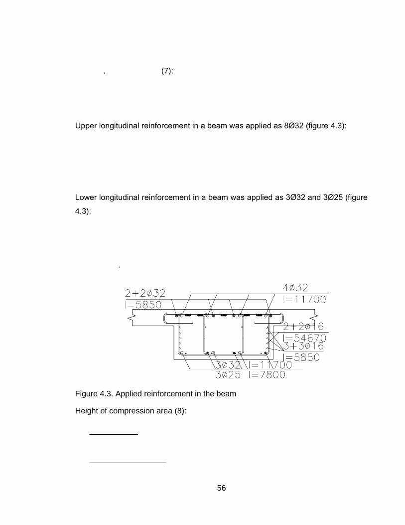
56
, (7);
Upper longitudinal reinforcement in a beam was applied as 8Ø32 (figure 4.3):
Lower longitudinal reinforcement in a beam was applied as 3Ø32 and 3Ø25 (figure
4.3):
.
Figure 4.3. Applied reinforcement in the beam
Height of compression area (8):

57
Plastic moment capacity of the beam (9):
2. Calculation of a slab
The material of the slab is concrete (B45) with reinforcement A500 and tendons –
Y1860. The slab was designed from element to element with thickness 200 mm
(figure 4.2). Conditions about initial data for calculations against progressive
collapse for slabs are the same with conditions for beams.
2.1 Plastic moment capacity in x-direction
was taken with reserve 3% due to post-tension tendons:
(7)
Longitudinal reinforcement for a slab in x-direction was applied as Ø8 s 200 (figure
4.4). Calculation was made for strip of width 1000 mm:

58
Figure 4.4. Applied reinforcement in the slab
Height of compression area (10):
(11).
Plastic moment capacity of the slab in x-direction (12):
Plastic capacity of the axial force of the slab in x-direction (13):

59
2.2 Plastic moment capacity in y-direction
was taken with reserve 3% due to post-tension tendons:
(7).
Longitudinal reinforcement for a slab in y-direction was applied as Ø10 s 200
(figure 4). Calculation was made for strip of width 1000 mm:
Height of compression area (14):
;
60
(11)
Plastic moment capacity of slab in y-direction (22):
Then it is possible to calculate capacity of structures (23):
For the first attempt necessary condition is not performed. So other options were
offered.
4.3.2 Attempt 2
In this case span is changed namely and the additional four supports (columns) are
included in work.

61
Figure 4.5. Model of removed column with changed span
1. Calculation of a beam
(7);
Upper longitudinal reinforcement in a beam was applied as 8Ø32 (figure 3):

62
Lower longitudinal reinforcement in a beam was applied as 3Ø32 and 3Ø25 (figure
4.3):
.
Height of compression area (when the upper reinforcement is compressioned) (8):
Plastic moment capacity of the beam (9):
Height of compression area (when the lower reinforcement is become
compressioned) (24):
Plastic moment capacity of the beam (25):
.
63
2. Calculation of a slab
2.1 Plastic moment capacity in x-direction
(7).
Longitudinal reinforcement for a slab in x-direction was applied as Ø8 s 200 (figure
4.4). Calculation was made for strip of width 1000 mm:
Height of compression area (10):
(11)
Plastic moment capacity of the slab in x-direction (12):
Plastic capacity of the axial force of the slab in x-direction (13):

64
2.2 Plastic moment capacity of the slab in y-direction
(7)
Longitudinal reinforcement for a slab in y-direction was applied as Ø10 s 200
(figure 4.4). Calculation was made for strip of width 1000 mm:
Height of compression area (14):
;
65
(11)
Plastic moment capacity of the slab in y-direction (22):
Capacity of structure in this case is calculated using (26):
Consideration of the supports did not help – condition is still not fulfilled.
4.3.3 Attempt 3
For this case the work of four supports and changed cross-section of reinforcement
in slab were taken into account.
1. Calculation of a beam
(7)
66
Upper longitudinal reinforcement in a beam was applied as 8Ø32 (figure 4.3):
Lower longitudinal reinforcement in a beam was applied as 3Ø32 and 3Ø25 (figure
4.3):
.
Height of compression area (when the upper reinforcement is compressioned) (8):
Moment capacity of the beam:
Height of compression area (when the lower reinforcement is become
compressioned) (24):
Moment capacity of the beam:

67
.
2. Calculation of a slab
2.1 Plastic moment capacity in x-direction
(7)
Longitudinal reinforcement for a slab in x-direction was applied as Ø12 s 200.
Calculation was made for strip with width 1000 mm:
Height of compression area (10):
(11)
Plastic moment capacity of the slab in x-direction (12):

68
The plastic capacity of the axial force of the slab (13):
2.2 Plastic moment capacity of the slab in y-direction
(7)
Longitudinal reinforcement for a slab in y-direction was applied as Ø16 s 200.
Calculation was made for strip with width 1000 mm:
Height of compression area (8):
(11)
Plastic moment capacity of the slab in y-direction:

69
Capacity of structure (26):
This attempt gave a good result but it is required to increase the cross sectional
area of reinforcement in the slab almost 1,5 times that can lead to excessive
reinforcement.
4.3.4 Attempt 4
Another attempt of the calculation was made with changed cross-sections of slabs
and beams (thickness and height) and considering the work of four supports.
Figure 4.6. Changed dimension of beam and slab
1. Calculation of the beam
The height of beam was changed – instead of 600 mm, 800 mm was applied
(figure 6).

70
(7)
Upper longitudinal reinforcement in a beam was applied as 8Ø32 (figure 4.3):
Lower longitudinal reinforcement in a beam was applied as 3Ø32 and 3Ø25 (figure
4.3):
.
Height of compression area (when the upper reinforcement is compressioned) (8):
Plastic moment capacity of the beam:
Height of compression area (when the lower reinforcement is become
compressioned) (24):
71
Plastic moment capacity of the beam:
.
2. Calculation of a slab
2.1 Plastic moment capacity in x-direction
(7).
Longitudinal reinforcement for a slab in x-direction was applied as Ø8 s 200 (figure
4.4). Calculation was made for strip of width 1000 mm:
Height of compression area (10):

72
(11
Plastic moment capacity of the slab in x-direction (12):
Plastic capacity of the axial force of the slab in x-direction (13):
2.2 Plastic moment capacity in y-direction
(7)
Longitudinal reinforcement for a slab in y-direction was applied as Ø10 s 200
(figure 4.4). Calculation was made for strip of width 1000 mm:
Height of compression area (8):
73
;
(11)
Plastic moment capacity of the slab in y-direction (22):
Capacity of the structure (26):
This attempt was successful. So the first finding can be made: the best solution to
provide necessary condition is increasing of elements’ cross-section or cross
sectional area of reinforcement.
To provide more reserve, it is possible to combine both solutions – increase the
dimension of elements and the cross sectional area of reinforcement.

74
4.3.5 Attempt 5
The important thing which should be considered in the calculation is using the post-
tensioned cables that take a significant part of the load. It is known that post-
tensioned reinforcement at ultimate limit state may show greater strength
compared to ordinary reinforcement. In this case it is needed to find out the
dependence of the deflection on the applied load – which allowed deflection should
be accepted to provide condition.
For this attempt of calculation the initial cross-section of elements and the amount
of reinforcement were applied. Cases without and with consideration of additional
columns were calculated.
1. Calculation of a beam
The material of the beam is concrete (B45) with reinforcement A500 and tendons –
Y1860. The beam has the following dimensions: height – 600 mm, width – 1200
mm and length – 16800 mm (figure 4.2).
, (7)
Upper longitudinal reinforcement in a beam was applied as 8Ø32 (figure 4.3):
Lower longitudinal reinforcement in a beam was applied as 3Ø32 and 3Ø25 (figure
4.3):

75
.
Height of compression area (8):
Plastic moment capacity of the beam (9):
.
In this case it is needed to consider the plastic capacity for the axial force for the
beam (27):
2. Calculation of slab
The material of the slab is concrete (B45) with reinforcement A500 and tendons –
Y1860. The slab was designed from element to element with thickness 200 mm
(figure 4.2).
2.1 Plastic moment capacity in x-direction

76
(7)
Longitudinal reinforcement for a slab in x-direction was applied as Ø8 s 200 (figure
4.4). Calculation was made for strip with width 1000 mm:
Height of compression area (10):
(11)
Plastic moment capacity of the slab in x-direction (12):
Plastic capacity of the axial force of the slab in x-direction (13):
2.2 Plastic moment capacity in y-direction

77
(7)
Longitudinal reinforcement for a slab in y-direction was applied as Ø10 s 200
(figure 4.4). Calculation was made for strip with width 1000 mm:
Height of compression area (8):
;
Plastic moment capacity of the slab in y-direction (22):
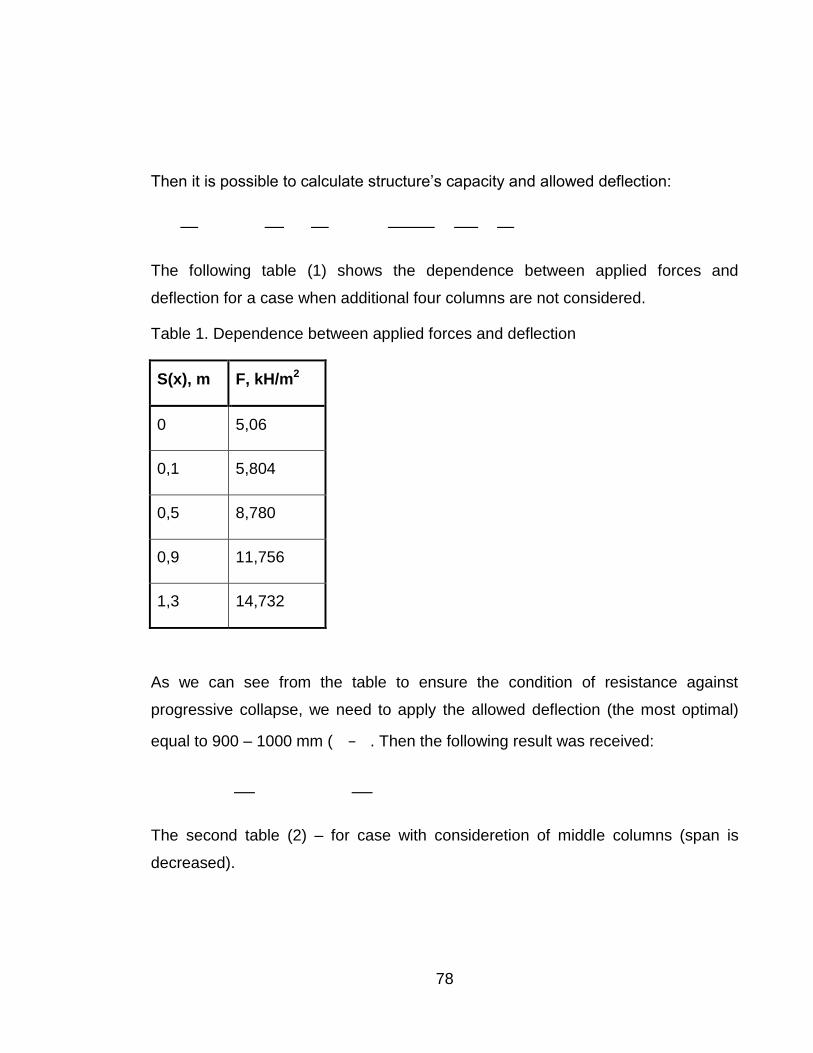
78
Then it is possible to calculate structure’s capacity and allowed deflection:
The following table (1) shows the dependence between applied forces and
deflection for a case when additional four columns are not considered.
Table 1. Dependence between applied forces and deflection
S(x), m F, kH/m2
0 5,06
0,1 5,804
0,5 8,780
0,9 11,756
1,3 14,732
As we can see from the table to ensure the condition of resistance against
progressive collapse, we need to apply the allowed deflection (the most optimal)
equal to 900 – 1000 mm ( . Then the following result was received:
The second table (2) – for case with consideretion of middle columns (span is
decreased).
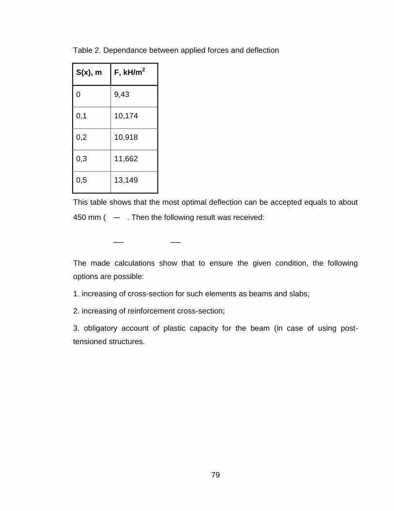
79
Table 2. Dependance between applied forces and deflection
S(x), m F, kH/m2
0 9,43
0,1 10,174
0,2 10,918
0,3 11,662
0,5 13,149
This table shows that the most optimal deflection can be accepted equals to about
450 mm ( . Then the following result was received:
The made calculations show that to ensure the given condition, the following
options are possible:
1. increasing of cross-section for such elements as beams and slabs;
2. increasing of reinforcement cross-section;
3. obligatory account of plastic capacity for the beam (in case of using post-
tensioned structures.

80
4.4 Conclusions
The main difference between ordinary calculation and calculation against
progressive collapse lies in used coefficients. The basic coefficients for such
calculation – coefficient of combinations , safety factor and material factors
should be applied equal to one.
Different combinations of removing a bearing vertical element should be
considered and checked to provide stability of structure (equilibrium between effort
in a structural elements and its bearing capacity).
Removal of any load-bearing vertical element increases the span of slabs and
beams and loads for the other elements that leads to appearance of plastic hinge
in the middle of the span and big deflection but damage is not accured. It can be
reached if the construction of beams and slabs is designed as membrane structure
which will withstand the part of enhanced loads. The membrane structure will take
vertical (with consideration of resistance to moment) and tension loads.
So when calculating reinforced concrete structures against progressive collapse it
is more suitable to choose the dimensions of the cross-sectional area for elements,
area of working reinforcement and mechanical properties of materials to provide
the maximum disclosure of the plastic hinge.
In this way during calcucation attempts were varied the size of cross section of
elements (beam and slab) and the area of reinforcement have been made to reach
the optimal balance between indicated characteristics and the value of deflection,
which allow to perform the condition (1) – stability of the structure under abnormal
loads.

81
5 SUMMARY
Designing structures to prevent progressive collapse is one of the unchallenged
imperatives in construction engineering of the time. Projecting for mitigating the risk
of progressive collapse requires various ways of thinking compared with ordinary
design to resist prescribed vertical and lateral loads. The design process should
concentrate on what could possibly go wrong and should determine the
performance requirements to be met. The team of design engineers should define
what exactly abnormal load events and damage schemes should be taken into
account and which are reasonable risk levels. So the purpose of this work was to
describe the phenomenon of progressive collapse and show the methods of
preventing or reducing it. That is why this chapter summarizes the main points
which were mentioned in the project.
5.1 Definition
For reducing the misunderstandings inter design professionals and with the public,
the common definition of the term “progressive collapse” should be adopted. The
following term can be a good version:
Progressive collapse is the spread of local damage, from an initiating event, from
element to element resulting, eventually, in the collapse of an entire structure or a
disproportionately large part of it (Bruce R. Ellingwood, 2007, p. 81), known as
disproportionate collapse, because of the collapse is out of proportion to the event
that triggers it. Thus, in structures susceptible to progressive collapse, small events
can cause catastrophic subsequences, like the gas explosion in Ronan Point
apartment or bomb explosion in Oklahoma.
As well for the decreasing the risk of collapse the potential abnormal loads that can
damaged the construction (like pressure and impact loads) should be taken into
account. During the design process the types of progressive collapse (pancake,
zipper, domino, and instability and section-type destruction) which depends on the
type of the structure and the initiating event also should be considered.

82
5.2 Design methods
As it was discussed earlier the existing two methods which are used to provide the
resistance from progressive collapse they are indirect method and direct method.
The indirect method is the implicit review of the resistance to progressive collapse
during the design process through providing the minimum levels of strength,
continuity and ductility between structural elements and connections. This method
can also supply the static indeterminacy by inclusion of additional interconnections
to provide spatial system operation, which make the structure more robust to
abnormal loads. Also this method is studied the risk of continues collapse in the
event of loss of structural elements, such things like redundancy, ties, ductility,
capacity for resisting load reversal. That is why these elements should be
considered and included in the project, because together they form robust
structures of restricting the spread of damage due to an initiating event. The direct
method consists of specific local resistance and the alternative load path method.
The specific local resistance method uses the key element which helps to resist the
threats or to make the strength of the whole system under load. The alternative
path method is a method which allows the local failure of the structure but seeks to
ensure alternate load path so that the damage is absorbed and the main collapse
does not happen. In this method the aim is to increase the redundancy of the
structure.
5.3 Calculation part
In this project the collapsing damage calculation was made to ensure the function
of building frame against loads described in Moscow regional standard
"Recommendations for high buildings protection against progressive collapse".
These calculations were done by using membrane action for rigid-perfectly plastic
model and cover the removal of columns.
First of all before the calculation process was considered such moment that the
basis coefficients as coefficient of combinations φ, safety factor and material
factors were taken equal to one. Then according the Moscow regional standard
one of the design scheme was chosen. Next the several calculation attempts were

83
made, where was seen how the structure will behave in a variety of design
conditions, for example, change of amount and cross section area of reinforcement
and modification the section of the structure (beam and slab).And after that the
conclusion was made that the removal of one column leads to the large
deformations in the slab. That is why internal tension forces in slab and beam are
carrying abnormal loads even in the case when the limit state in beams under the
influence of the bending moment is reached. Thus the whole construction is not
damaged and there is no progressive collapse. Also the local deformations can
occur, but the whole structure will stand. Then it was considered, that all structures
due to the level +12.600 will survive. But only if the section of the height of the
beam is changed (increased) or enhanced the cross-section area of reinforcement
in slab and the work of additional columns is taken into account.
5.4 Norms and standards
The existence and positional effects of abnormal loads and possibility of
progressive collapse should be directly shown in codes and norms. As for the
European countries and the USA, in these regions is rather good and wide opened
question for design and prevention structures from progressive collapse. That
cannot be said about Russian norms. There is no SNIP or SP, which explains and
shows step by step how to design a structure, which will resist the progressive
collapse. However, there are several recommendations for the design and
calculation process, but they are only for Moscow region. So it is hoped that in the
future code (norms) development leads to create and approve the design
requirements, design objectives, design methods, verifications and calculation
procedures for the whole country. And it is also hoped that the question about
progressive collapse will be extensively discussed and researched among Russian
structural engineers.

84
LIST OF SYMBOLS
Latin upper case letters
cross sectional area of concrete area of a prestressing tendons
cross sectional area of reinforcement module elasticity for concrete module elasticity for reinforcement
effort in a structural elements
plastic moment capacity of the beam at the support permissible plastic longitudinal force in the beam
design value of the applied axial force design yield strength of reinforcement
normative values of resistance to tension
design yield strength of tendons
bearing capacity of structures
Latin lower case letter
width of beam effective depth of a cross-section
thickness of concrete cover design value of concrete compressive strength
dead load height of beam dynamic load factor
span plastic moment capacity of the slab in x-direction
plastic moment capacity of the slab in y-direction
plastic capacity of the axial force of the slab
live load thickness of slab
deflection relative height of compression area
Greek lower case letters
coefficient of working conditions coefficient of reliability for concrete
safety factor safety factor for reinforcement density of concrete coefficient of combination
height of compression area

85
FIGURES
Figure 2.1. The stages of the pancake-type progressive collapse, p. 9
Figure 2.2. the stages of zipper-type progressive collapse, p. 11
Figure 2.3. The stages of domino-type progressive collapse, p. 13
Figure 2.4. The stages of instability-type progressive collapse, p. 15
Figure 2.5. Different types of ties incorporated to provide structural integrity, p. 18
Figure 2.6. Alternative path method an example of removal column, p. 28
Figure 2.7. The balance condition for beam and catenary action, p. 29
Figure 2.8. The plan of the flat at 18th floor, p. 32
Figure 2.9. Ronan Point after collapse, p. 32
Figure 2.10. Exterior horizontal joint between floor slab and flank wall as built, p. 33
Figure 2.11. Joint wall panel with a parapet, p. 34
Figure 2.12. The north facade of the building, p. 36
Figure 2.13. The north façade after collapse, p. 36
Figure 2.14. The destroyed elements of the building, p. 37
Figure 2.15. The process of continues collapse of Murrah building, p. 37
Figure 2.16. Pre-Collapse position of building elements in Murrah, p. 38
Figure 3.1.The shape of yield lines when a column is notionally removed, p. 45
Figure 4.1. Model of removed column, p. 54
Figure 4.2. Section of beam and slab, p. 55
Figure 4.3. Applied reinforcement in the beam, p. 56
Figure 4.4. Applied reinforcement in the slab, p. 58
Figure.4.5. Model of removed column with changed span, p. 61
Figure 4.6. Changed dimensions of beam and slab, p. 69

86
TABLES
Table 1. Dependence between applied forces and deflection, p. 78
Table 2. Dependence between applied forces and deflection, p. 79
87
REFERENCES
Starossek Uwe. 2009. Progressive collapse of structures. London: Thomas Telford Limited.
Digesh Joshi, Paresh Patel. 2012. Progressive collapse analysis. Saarbrucken: Lambert Academic Publishing.
Ellingwood Bruce R. 2007. Best Practices for reducing the potential for progressive collapse in buildings. NISTIR, USA.
STO-008-02495342-2009. 2009. Prevention progressive collapse of monolithic concrete constructions.
MDS 20-2.2008. Temporary Recommendations for making safety conditions for large span structures from progressive collapse in dangerous impacts.
Räty J. 2010. Limiting the extent of localised failure according to SFS-EN 1991-1-7. Aalto University. Degree Programme in Construction Engineering. Master’s Thesis.
Delatte, N. J. 2009. Beyond failure: Forensic case studies for civil engineers. American Society of Civil Engineers (ASCE), Reston, Virginia, 97-106.
Levy, M., and Salvadori, M. 1992. Why buildings fall down: How structures fail. W.W. Norton, New York, 76-83.
Pearson, C.,and Delatte, N. J. 2005. Ronan Point Apartment Tower Collapse and Its Effect on Building Codes. J. Perf. of Constr. Fac., 19(2), 172-177.
Corley, W. G., Mlakar, P. F., Sozen, M. A., Thorton, C. H. 1998. “The Oklahoma City Bombing: Summary and Recommendations for Multi-hazard Mitigation,” J. Perf. of Constr. Fac., ASCE, 12(3), 100-112.
Hinman, E. E., and Hammond, D. J. (1997). Lessons from the Oklahoma City Bombing, Defensive Design Techniques, ASCE Press, New York.
Skinev A. N. 1984. ACCIDENTS IN CONSTRUCTION. Moscow: Stroiizdat
Marchand Kirk A. and Alfawakkhiri F. 2005. Blast and progressive collapse. American institute of Steel Construction, Inc.
"Engineering" the Collapse: Making the Structure Safe- Fire Engineering. 1995. http://www.fireengineering.com/articles/print/volume-148/issue-11/features/engineering-the-collapse-making-the-structure-safe.html (Accessed on 11 April 2013)
Ronan Point Apartment Tower (May 16, 1968). Wikispaces. 2009.
http://failures.wikispaces.com/page/diff/Ronan+Point/152990661 (Accessed on 2
April 2013)
Murrah Federal Office Building (April 19, 1995). Wikispaces. 2009. http://failures.wikispaces.com/Murrah+Federal+Building (Accessed on 12 April 2013)
Shankar Nair R. 2004. Progressive Collapse Basics. Modern Steel Construction, pp. 1-3.

APPENDIX 1
1(9)
Example of calculation of the structure
Calculations were made for block 1 at level +7.200. The removed column is
situated at the intersection of axis 3/E. This column is in-situ concrete element
(B40) with square section 600x600 mm.
Figure 1. Model of removed column with work of additional columns
1 External loads
Dead load (self-weights of slab and beam):
Live load:
The total load with load factor equals to 1,0 (6):
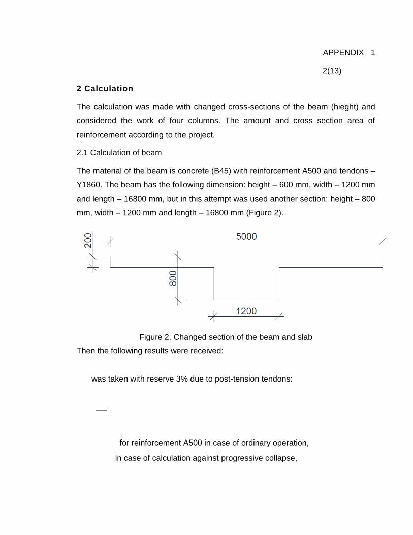
89
APPENDIX 1
2(13)
2 Calculation
The calculation was made with changed cross-sections of the beam (hieght) and
considered the work of four columns. The amount and cross section area of
reinforcement according to the project.
2.1 Calculation of beam
The material of the beam is concrete (B45) with reinforcement A500 and tendons –
Y1860. The beam has the following dimension: height – 600 mm, width – 1200 mm
and length – 16800 mm, but in this attempt was used another section: height – 800
mm, width – 1200 mm and length – 16800 mm (Figure 2).
Figure 2. Changed section of the beam and slab
Then the following results were received:
was taken with reserve 3% due to post-tension tendons:
for reinforcement A500 in case of ordinary operation,
in case of calculation against progressive collapse,
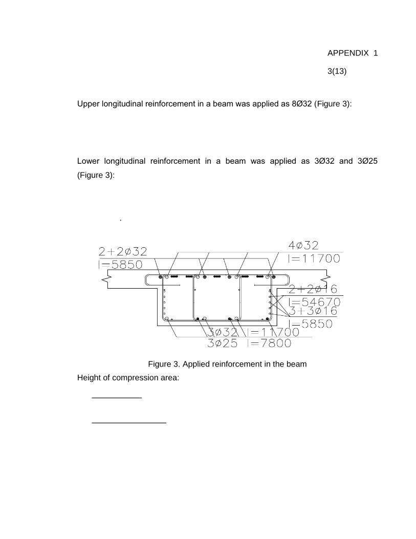
90
APPENDIX 1
3(13)
Upper longitudinal reinforcement in a beam was applied as 8Ø32 (Figure 3):
Lower longitudinal reinforcement in a beam was applied as 3Ø32 and 3Ø25
(Figure 3):
.
Figure 3. Applied reinforcement in the beam
Height of compression area:

91
APPENDIX 1
4(13)
Plastic moment capacity of the beam:
.
Height of compression area (when the lower reinforcement is become
compressioned):
Plastic moment capacity of the beam:
.
2.2 Calculation of slab
Conditions about initial data for calculations against progressive collapse for slabs
are the same and the thickness of slab is 200 mm.
2.2.1 Plastic moment capacity in x-direction:

92
APPENDIX 1
5(13)
Longitudinal reinforcement in x-direction was applied as Ø8 s 200 (Figure 4).
Calculation was made for strip with width 1000 mm:
Figure 4. Applied reinforcement in the slab

93
APPENDIX 1
6(13)
Height of compression area:
Plastic moment capacity of the slab in x-direction:
Plastic capacity of the axial force of the slab in x-direction:
2.2.2 Plastic moment capacity of the slab in y-direction
Longitudinal reinforcement in y-direction was applied as Ø10 s 200 (Figure 4).
Calculation was made for strip with width 1000 mm:

94
APPENDIX 1
7(13)
Height of compression area:
;
Plastic moment capacity of the slab in y-direction:
Capacity of structure in this case is calculated:

95
APPENDIX 1
8(13)
Below the allowed value of the external load as a function of the deformation in the
removed column is shown.
2.3. Calculation of beam with the initial parameters
First it is need to be calculated all moments in beam. So is used the in-situ
concrete beam(B45) with reinforcement A500 and tentonds Y1860. Beam has the
following dimensions: height – 600 mm, width – 1200 mm and length – 16800 mm.
,
Upper longitudinal reinforcement in a beam was applied as 8Ø32 (Figure 3)::
Lower longitudinal reinforcement was applied as 3Ø32 and 3Ø25 (Figure 3):
96
APPENDIX 1
9(13)
.
Height of compression area:
Plastic moment capacity of the beam:
.
Height of compression area (when the lower reinforcement is become
compressioned):
Plastic moment capacity of the beam:
.

97
APPENDIX 1
10(13)
Also it is needed to consider the plastic capacity for the axial force for the beam:
2.4 Calculation of slab with the initial parameters
Material of slab is concrete (B45) with reinforcement A500 and tendons – Y1860.
The slab was designed from element to element with thickness 200 mm (Figure 2).
Conditions about initial data for calculations against progressive collapse for slabs
are the same with conditions for beams.
2.4.1 Moment capacity in x-direction
Longitudinal reinforcement in x-direction was applied as Ø8 s 200 (Figure 4).
Calculation was made for strip with width 1000 mm:

98
APPENDIX 1
11(13)
Height of compression area:
Plastic moment capacity of the slab in x-direction:
Plastic capacity of the axial force of the slab in x-direction:
2.2.2 Moment capacity in y-direction
Longitudinal reinforcement in y-direction was applied as Ø10 s 200 (Figure 4).
Calculation was made for strip with width 1000 mm:

99
APPENDIX 1
12(13)
Height of compression area:
;
Plastic moment capacity of slab in y-direction:
Then it is possible to calculate internal forces:
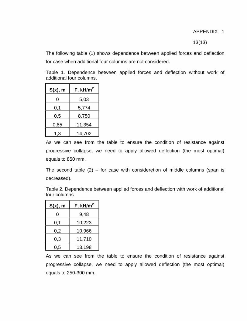
100
APPENDIX 1
13(13)
The following table (1) shows dependence between applied forces and deflection
for case when additional four columns are not considered.
Table 1. Dependence between applied forces and deflection without work of additional four columns.
S(x), m F, kH/m2
0 5,03
0,1 5,774
0,5 8,750
0,85 11,354
1,3 14,702
As we can see from the table to ensure the condition of resistance against
progressive collapse, we need to apply allowed deflection (the most optimal)
equals to 850 mm.
The second table (2) – for case with consideretion of middle columns (span is
decreased).
Table 2. Dependence between applied forces and deflection with work of additional four columns.
S(x), m F, kH/m2
0 9,48
0,1 10,223
0,2 10,966
0,3 11,710
0,5 13,198
As we can see from the table to ensure the condition of resistance against
progressive collapse, we need to apply allowed deflection (the most optimal)
equals to 250-300 mm.

101
APPENDIX 2
1(12)
Example of calculation of the structure
Calculations were made for block 1 at level +12.600. The removed column is
situated at intersection of axis 11/C. This column is in-situ concrete element (B40)
with square section 600x600 mm.
Figure 1. Model of removed column with work of additional columns
1 External loads
Dead load (self-weights of slab and beam):
Live load:
Total load with load factor equals to 1,0 (6):
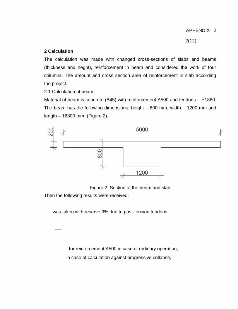
102
APPENDIX 2
2(12)
2 Calculation
The calculation was made with changed cross-sections of slabs and beams
(thickness and heght), reinforcement in beam and considered the work of four
columns. The amount and cross section area of reinforcement in slab according
the project.
2.1 Calculation of beam
Material of beam is concrete (B45) with reinforcement A500 and tendons – Y1860.
The beam has the following dimensions: height – 800 mm, width – 1200 mm and
length – 16800 mm, (Figure 2).
Figure 2. Section of the beam and slab
Then the following results were received:
was taken with reserve 3% due to post-tension tendons:
for reinforcement A500 in case of ordinary operation,
in case of calculation against progressive collapse,

103
APPENDIX 2
3(12)
Upper longitudinal reinforcement in beam was applied as 2Ø25 and 4Ø32 (Figure
3):
Lower longitudinal reinforcement in a beam was applied as 4Ø16 (Figure 3):
.
Figure 3. Applied reinforcement in beam according the project
Height of compression area:
Plastic moment capacity of the beam:

104
APPENDIX 2
4(12)
Height of compression area (when the lower reinforcement is become
compressioned):
Plastic moment capacity of the beam:
.
2.2 Calculation of slab
Conditions about initial data for calculations against progressive collapse for slabs
are the same. In this case the thickness of slab was changed – instead of 200 mm,
250 mm was taken.
2.2.1 Plastic moment capacity in x-direction:
Longitudinal reinforcement in x-direction was applied as Ø8 s 200 (Figure 4).
Calculation was made for strip with width 1000 mm:

105
APPENDIX 2
5(12)
Figure 4. The Applied reinforcement in a beam
Height of compression area:
106
APPENDIX 2
6(12)
Plastic moment capacity of the slab in x-direction:
Plastic capacity of the axial force of the slab in x-direction:
2.2.2 Plastic moment capacity in y-direction
was taken with reserve 3% due to post-tension tendons:
Longitudinal reinforcement in y-direction was applied as Ø10 s 200 (figure 5, 6).
Calculation was made for strip with width 1000 mm:
Height of compression area:
107
APPENDIX 2
7(12)
;
Plastic moment capacity of the slab in y-direction:
Then it is possible to calculate structure’s capacity:
Below the allowed value of the external load as a function of the deformation in the
removed column is shown.
2.3. Calculation of beam with the initial parameters
First it is need to be calculated all moments in the beam. So is used the in-situ
concrete beam(B45) with reinforcement A500 and tentonds Y1860. Beam has the
following dimensions: height – 800 mm, width – 1200 mm and length – 16800 mm.

108
APPENDIX 2
8(12)
,
Upper longitudinal reinforcement was applied as 2Ø25 and 4Ø32 (Figure 3):
Lower longitudinal reinforcement was applied as 4Ø16 (Figure 3):
.
Height of compression area:
Plastict moment capacity of the beam:
.
Height of compression area (when the lower reinforcement is become
compressioned):

109
APPENDIX 2
9(12)
Plastic moment capacity of the beam:
.
Also it is needed to consider the plastic capacity for the axial force for the beam:
2.4 Calculation of slab with the initial parameters
Material of slab is concrete (B45) with reinforcement A500 and tendons – Y1860.
The slab was designed from element to element with thickness 200 mm (Figure 2).
Conditions about initial data for calculations against progressive collapse for slabs
are the same with conditions for beams.
2.4.1 Plastic moment capacity in x-direction
Longitudinal reinforcement in x-direction was applied as Ø8 s 200 (figure 5, 6).
Calculation was made for strip with width 1000 mm:

110
APPENDIX 2
10(12)
Height of compression area:
Plastic moment capasity of the slab in x-direction:
Plastic tension capacity in x-direction:
2.2.2 Plastic moment capasity of the slab in y-direction
Longitudinal reinforcement in y-direction was applied as Ø10 s 200 (figure 5, 6).
Calculation was made for strip with width 1000 mm:

111
APPENDIX 2
11(12)
Height of compression area:
;
Plastic moment capasity of the slab in y-direction:
Then it is possible to calculate internal forces:
The following table (1) shows dependence between applied forces and deflection
for case when additional four columns are not considered.
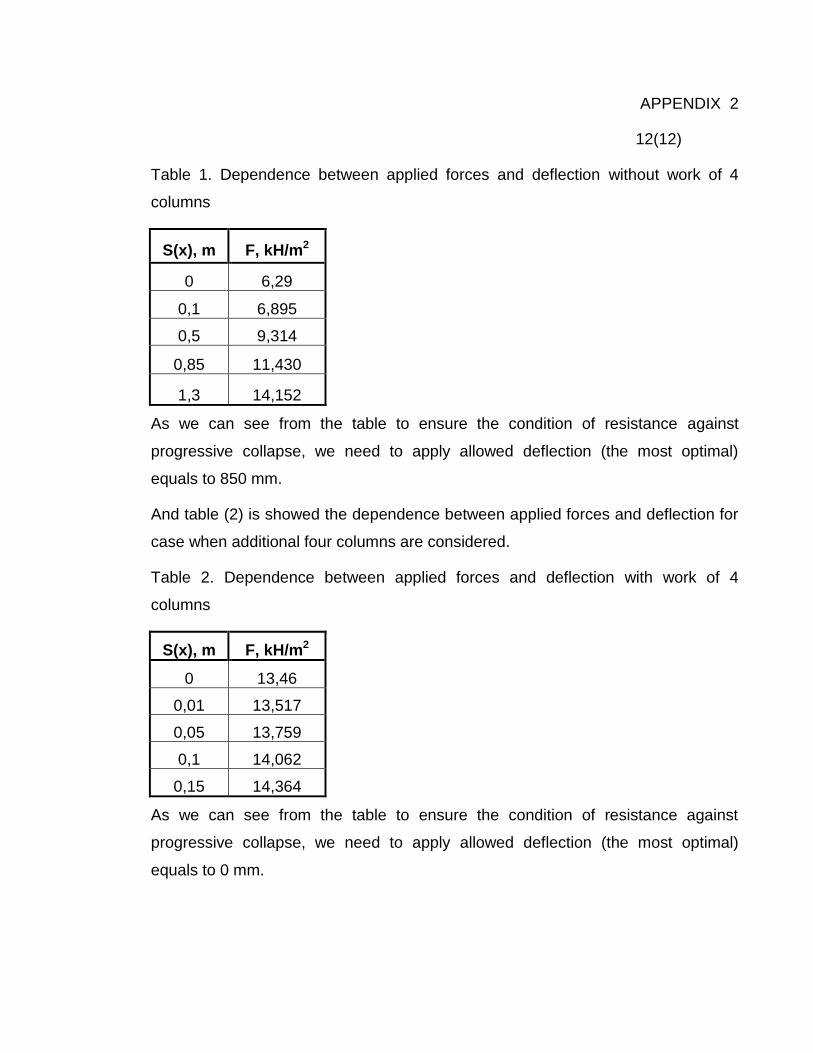
112
APPENDIX 2
12(12)
Table 1. Dependence between applied forces and deflection without work of 4
columns
S(x), m F, kH/m2
0 6,29
0,1 6,895
0,5 9,314
0,85 11,430
1,3 14,152
As we can see from the table to ensure the condition of resistance against
progressive collapse, we need to apply allowed deflection (the most optimal)
equals to 850 mm.
And table (2) is showed the dependence between applied forces and deflection for
case when additional four columns are considered.
Table 2. Dependence between applied forces and deflection with work of 4
columns
S(x), m F, kH/m2
0 13,46
0,01 13,517
0,05 13,759
0,1 14,062
0,15 14,364
As we can see from the table to ensure the condition of resistance against
progressive collapse, we need to apply allowed deflection (the most optimal)
equals to 0 mm.