progress report - experts mindsecure.expertsmind.com/attn_files/74_progress report of...
TRANSCRIPT

School of Science, Information Technology and
Engineering
ENCOR 7020 Research Methodology
Progress Report
ByJagmeet Singh Dhillon
30129527
To
Dr Ibrahim Sultan
Contents
Jagmeet Singh Dhillon30129527

LIST OF FIGURES
TITTLE - Optimization of the thermal performance of flat plate solar water
heater via flow rate setting.
1. PROBLEM STATEMENT
The conservation of sun energy into usable forms through conventional and modern
processes sometimes requires remodification in material and working fluid being
used to produce it. To alter mechanical land chemical properties of material and
working fluid there are pretty many processes are being used and developed.
Methods like concentrated evacuated tube solar water heating, flat plate solar water
heating, Photovoltaic, Active and passive solar water heating.
Solar hot water has come a long way in the last decade, particularly with the introduction of
evacuated tube collectors that are rapidly becoming the preferred option. Evacuated tube
solar water heating (as the name suggests) consist two glass tubes fused at the top and
bottom. The space between the two tubes is evacuated to form a vacuum. A copper pipe
(called a heat pipe) running through the centre of the tube meets a common manifold that is
then connected to a slow flow circulation pump that pumps water to a storage tank below,
thus heating the water during the day. The hot water can be used at night or the next day
due to the insulation of the tank.

The evacuation tube systems are superior as they can extract the heat out of the air on a
humid day and don’t need direct sunlight. Due to the vacuum inside the glass tube, the total
efficiency in all areas is higher and there’s better performance when the sun is not at an
optimum angle – such as when it’s early in the morning or in the late afternoon. (Mobin
Arab 2013)
Figure 1/Evacuated tube solar water heating (manufacturar 2015)
Flat plate solar water heating collector are conventional and oldest proven
technology for introducing the concept of solar water heating. A flat-plate collector
consists of an absorber, a transparent cover, a frame, and insulation. Usually a low
iron safety glass is used as a transparent cover as it lets trough a great amount of
the radiation from the sun. Simultaneously, only very little of the heat emitted by the
absorber escapes the cover (greenhouse effect). In addition, the transparent cover
prevents wind from cooling the absorber. Together with the frame, the cover protects
the absorber from adverse weather conditions. . (T. Rajaseenivasan a 2014)
Unlike the concentrated collectors, flat plate concentrators collate solar
energy in non-concentrated manner (Davabkhaktuni et al., 2013), and are
Jagmeet Singh Dhillon30129527

predominantly used for heating and cooling purposes. With the relatively low cost
associated with the technology, its use has been on the increase in the recent years.
In principle, the technique allows for heating or cooling of fluids within a highly
controlled environment (Zhu 2010). As a consequence, their use in electric water
heating has lately caught pace, with prospective increase in the next several years.
The functional capacity of these systems is embedded on their ability to
absorb, transfer and at times store energy. Whilst the harnessed or stored power can
be used in heating the water, copper tubing coated with suitable absorbent material
are used in optimizing the absorption (Davabkhaktuni et al., 2013, p.558). When the
water is circulated in the tubing, it is heated before being moved to the storage
reservoir.
The
PVT(Photovoltaic thermal system ) as combination photovoltaic and thermal
technology. of Regards photovoltaic thermal solar water heating is most utilisation
technology for solar water heating. It working inversly affected as temperature rise.
The experiments exhibits that 10 rise in temperature reduces photovoltaic efficiency
accounts for 0.4%. However photovoltaic efficiency lies between 4% to 17% for
simple solar cell (M. Boubekri a 2013). In this working fluid can be heated through
heat collector which classified as concentrating and non-concentrating. A

concentrating heat collector utilised for low temperature application whereas non
concentrating for high temperature application. Moreover, low cost solar thermal
technology has a poor photo- thermal efficiency.
Figure 2/ Photovoltaic thermal solar water heating system
(M. Boubekri a 2013)
From the past years, many researches has been conducted on combination of both
photovoltaic and solar thermal, investigation about design and working operation.
The modification are made in proposed design to enhance heat abstraction process.
The overall performance of combination was improved as compared to other solar
systems. The basic principle of PVT System is to utilise the wastage heat from PV
modules to heat water by working fluid. Fig4, represents the schematic flow of
working fluid attached with PV module.
Jagmeet Singh Dhillon30129527

Figure 3/Photovoltaic - solar thermal water heating with PV module (Feng Shan
2013)
A literature review clearly indicates that each process is capable of heating water as
per as depending on the needs. The processes used for generating energy have
some shortcoming when compared within themselves and every process is not
effective as other is on same type of material and working fluid using, taking
advantages of this drawback it was decided to undertake the study which should
identify what are the effects on solar water heater with varying flow rate. In this
study it is decided to optimize thermal performance in term of effect on solar water
heater so that a common understanding can be built to know that how change in flow
rate of fluid effect the system taking many factor into consideration like effect of
orientation, season and different weather conditions. So that more effective results
can be obtained in experimental investigations.
2. LITERATURE SURVEY
To improve thermal properties of various working fluids such as water, acetone,
methanol, propane, ammonia, ethylene glycol numerous research are developed in
last few decades to investigate the effect of different types of solar water heaters
(P.V. Durga Prasad a 2015). All of above said working fluids have advantages and
disadvantages and in this study thermal performance of flat plat solar water have
been studied. A working fluid “water” has been taken into consideration for testing.

Passive solar water heating system is selected to investigate the properties of
different fluids as elimination of forced pump. In proposed system water tank
is installed above the solar heat collector and fluid flow by natural convection.
(HC 2013)
Optical and thermal performances improvement of an ICS solar water heater systems
This paper is generated as new design of integrated collector storage (ICS) solar
water heater with a compound parabolic concentrator (CPC) so as to enhance the
quantity and improvement in optical and thermal performance of system. This
system was generated to simulate the reflection of the direct solar radiation on the
CPC reflector at various angles of incidence to find out absorbed solar radiation
distribution on the absorber surface. The results are compared with the old
experiment to check the improvement of temperature level and in angle of incident.
A ray tracing technique is used to investigate the optical performance. In this
technique, combination of ICS and CPC, direct solar radiation only compared in
CPC. The energy formed can be calculated by distributing direct solar rays around
the absorber at different angle of incidence. A two dimensional ray tracing technique
has wide applicable in calculate the energy distribution at the observer surface and
line axis asymmetric compound parabolic concentrator, also find out optical
efficiency as function of angle of incident for selected compound parabolic
concentrator. Several assumption are made in this research which are as follows
1. Angle of incident is equal to angle of reflection.
2. All rays of interest are specular.
3. The incident direct solar flux at the aperture is considered to be a number of
parallel rays, carrying equal amounts of energy.
4. Vector forms of refraction and reflection laws are applicable to ray trace in the
solar system.
5. A ray entering, strikes the absorber with no previous reflections.
Jagmeet Singh Dhillon30129527

Figure 4/ Ray trace diagram for old system at angle of incidence 0 degree (Raouf
Benrejeb Feb, 2015)
Figure 5/ Ray trace diagram for new system at an angle of incidence 20 degree
(Raouf Benrejeb Feb, 2015)

The results are evaluated, making comparison with old system at different angle of
incidents i.e. 00, 200. Increase in angle of incidence results in reduction of absorbed
flux energy. In new design system, all rays are reflected towards absorbed through
some reflections while in old system it went outside. For negative (-) angle, new
system acts as an asymmetrical reflector. At -20 degree, all rays are concentrated
only at left portion, no rays are on right portion and on upper there are only direct
rays. Coming to – 40 degree, absorber receive only at lower end of left side. (Raouf
Benrejeb Feb, 2015)
Model-based design and analysis of heat pipe working fluid for optical performance in
a concentric evacuated tube solar water heater
This paper is talks about to develop a fully integrated model for a grooved type
evacuated tube solar water heater and validated against experimental data. It
depends upon the working of different fluids; here three working fluids are used to
detect the effect of working fluid change in a real evacuated tube solar water heater.
It was resulted that significantly that higher performance of solar water heater is
achievable by improving the working fluid properties and economic performance that
accounts for 84% and 50% respectively.
Jagmeet Singh Dhillon30129527

Figure 6/Variation in Thermal resistance w.r.t Time (Mobin Arab 2013)
The two main components that affect the result are thermal resistance and heat
transfer capacity. In this study, total 20 pipes are taken into account in the solar water
heater and water flow rate is changed with variation in time. The result is generated,
effect on thermal performance with changing the fluid in solar water heater during
day time. In water filled heat pipe, the thermal resistance of evacuated section
declines as solar isolation resulted in hike of saturation temperature. More
significantly, thermal resistance remains unchanged during the day. This reveals that
rise in condenser thermal resistance results in drop of evaporator thermal resistance.
Figure 7/ Modelled System (Mobin Arab 2013)
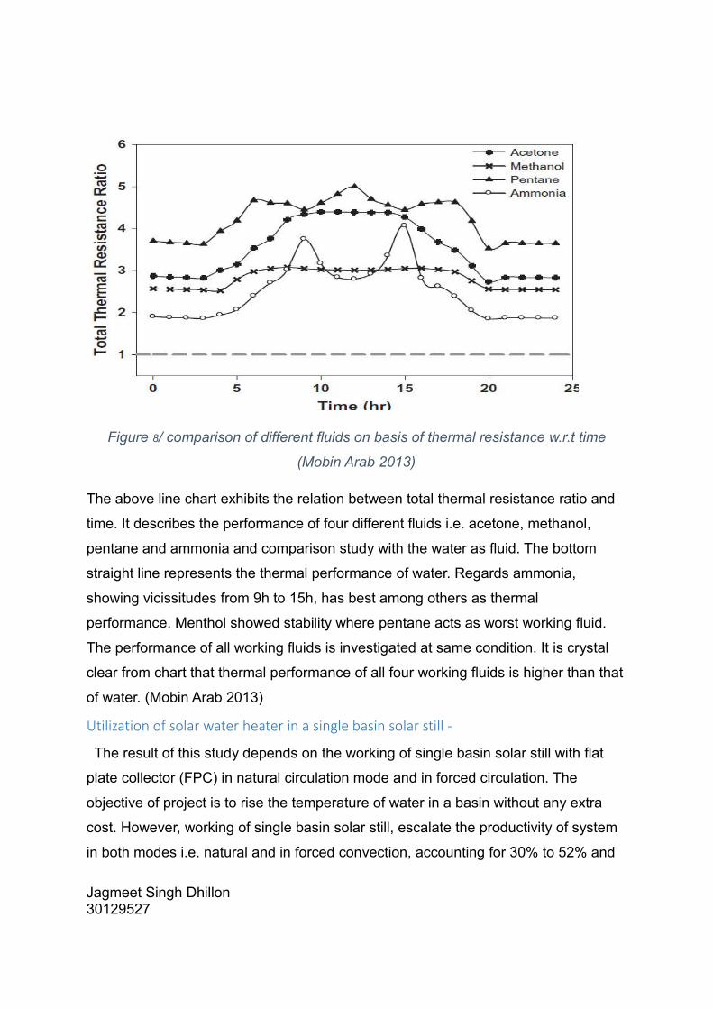
Figure 8/ comparison of different fluids on basis of thermal resistance w.r.t time
(Mobin Arab 2013)
The above line chart exhibits the relation between total thermal resistance ratio and
time. It describes the performance of four different fluids i.e. acetone, methanol,
pentane and ammonia and comparison study with the water as fluid. The bottom
straight line represents the thermal performance of water. Regards ammonia,
showing vicissitudes from 9h to 15h, has best among others as thermal
performance. Menthol showed stability where pentane acts as worst working fluid.
The performance of all working fluids is investigated at same condition. It is crystal
clear from chart that thermal performance of all four working fluids is higher than that
of water. (Mobin Arab 2013)
Utilization of solar water heater in a single basin solar still -
The result of this study depends on the working of single basin solar still with flat
plate collector (FPC) in natural circulation mode and in forced circulation. The
objective of project is to rise the temperature of water in a basin without any extra
cost. However, working of single basin solar still, escalate the productivity of system
in both modes i.e. natural and in forced convection, accounting for 30% to 52% and
Jagmeet Singh Dhillon30129527

50% respectively with collaborated with flat plate collector. Moreover its performance
varied with coupling with different equipment.
Figure 9/ Change in temperature with different intervals of time through a day (K.
Sampathkumar 2012)
Figure 10/ variation in yield strength with day timing (K. Sampathkumar 2012)
The above results had been as we can see from the line chart, which demonstrates
that inner glass temperature and water temperature, effects most the yield
calculation because there are only variation in water generated, temperature, and
inner glass temperature and yield strength. Yield strength showed its peak at mid-
day between 11 am to 4 pm. It can be concluded that it increased as temperature
rise. In fig 3(1), the variations in both temperatures vis-à-vis whole day time .The
temperature rise in both are owing to extra thermal energy supplied by evacuated
tube collector in basin. So it can be concluded that average performance is

escalated, when single still coupled with evacuated tube collection. (K.
Sampathkumar 2012)
Effect of orientation on the performance of a symmetric solar still with a
Double effect solar still (comparison study)
The proposed design informed about the effect of orientation on two different slit i.e.
symmetric double solar slit and asymmetric solar slit, under different climatic
conditions. A computer program has been generated to express the result, which
described that both the stills received a maximum solar radiation at optimum
inclination angle 100. As seen, south –north orientation increase the performance
constituting 16.75% with single still as it is most stable among other direction.
Regarding double slop system, east-west orientation and south-north orientation
resulted in 16.23% and 22.75% respectively.
Notified above diagrams, at east-west direction, solar radiation touched its acme for
both the stills at different angles of inclination at different time. Whereas, solar
radiation acceptance is highest for all different angles for both the stills. (Trad
Abderachid 2012)
Performance of copper oxide/water Nano fluid in a flat plate solar water
Heater under natural and forced circulations
The research based on, thermal performance of copper oxide/water Nano fluid was
investigated on a 100 Littre per day (LPD) thermosiphon based indirect-type flat plat
solar water heater. Thermosyphon and forced circulation are compared on the basis
of different properties. For mass flow rate, forced circulation was witnessed higher
frequency vis-a-vis thermosyphon circulation. Overall, thermosyphon was slight an
edge over forced.
Jagmeet Singh Dhillon30129527

Figure 11/ XRD image of Nanoparticles (Jee Joe Michael 2015)
The performance of copper-oxide nanoparticles are compared with water in
thermosiphon and two forced circulation conditions in solar water heater. The result
based on comparison study of different techniques or Nano characterization tests,
which is not identical for all. X-ray diffract meter (XRD) is used to developed the
crystal structure and purity of the CuO particles. (Jee Joe Michael 2015)
Life cycle environmental impact assessment of a solar water heater
The proposed design reveals about the investigation of technical and environment
effect with life cycle assessment (LCA) on performance of solar water heater. The
main motive of study is to produce electricity for domestic and auxiliary use with
lesser emission. The process centralised manufacturing stages, resource
consumption and avoid wastage to the environment. The model include the
assembly and manufacturing of parts of solar water heater like heat storage tank,
solar collector, component box and aperture by concentrating many environment
impacts like ozone depletion, acidification, greenhouse effect etc.
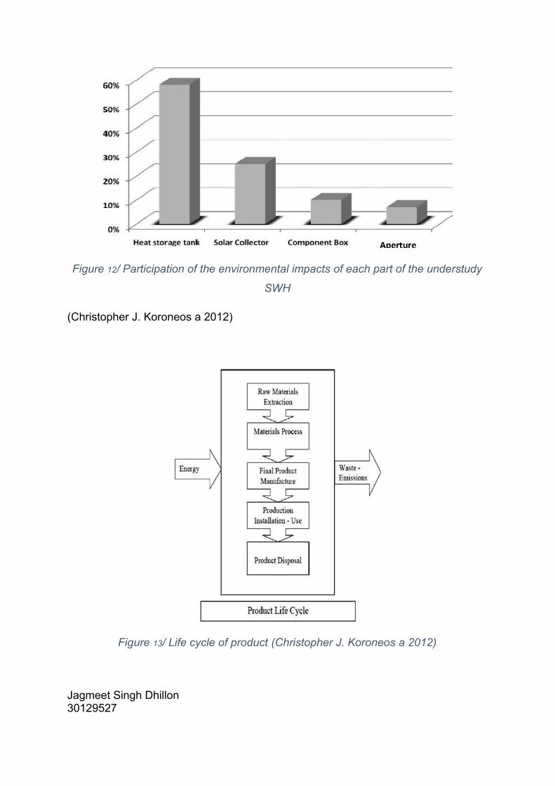
Figure 12/ Participation of the environmental impacts of each part of the understudy
SWH
(Christopher J. Koroneos a 2012)
Figure 13/ Life cycle of product (Christopher J. Koroneos a 2012)
Jagmeet Singh Dhillon30129527

Life cycle inventory included waste material extraction from starting to end life of
solar water heater. Moreover, environmental effects are considered as the
installation of heat storage tank, solar collector, component box and other apparatus
in manufacturing SWH (Christopher J. Koroneos a 2012)
Experimental study on thermosyphon solar water heater in Bahrain
In the present data, thermal properties thermosyphon water heater unit was
examined, using a many sunny, cloudy and hazy days to check applicability in
Bahrain in winter season. Result was collected and revealed that model is well
suitable for application in Bahrain climate conditions. The results are developed,
when storage water temperature is above 500 then the efficiency of process is 38%.
The isolation rises as it reaches its peak value i.e. 695 W/m at the mid-day after it
starts declined. (A.A. Karaghouli a 2001)
(A.A. Karaghouli a 2001)
The above line chart describes the variation in different temperature w.r.t time. In canbe concluded that all temperatures (Tin, Tout and Tstorg) showed escalation as from morning to afternoon and started decline after 3pm.
The performance of a cylindrical solar water heater
This study gave knowledge about how to calculate the performance of cylindrical
solar water heater was experimentally performed, having a different dimensions
Results came to for that it is capable of producing heat energy from sun energy but

expensive than flat plate collector. It consists of spiral copper tube having inner and
outer diameter 0.14 and 6mm respectively. The efficiency of was detected, that value
during the change of temperature at inlet and outlet temperature is 41.8% and mass
flow rate calculated is 9 kg/h. This study also lay emphasis on the comparison
between cylindrical and flat plate collector. (Al-Madani 2006)
Figure 14/Efficiency versus time of day
In this paper, to check performance of the cylindrical solar water heater different parameters were calculated. As follows,
1. Instantaneous Efficiency2. Useful energy gained(Qu)3. Overall coefficient of heat losses(U)4. Collector heat removal factor (FR)5. Absorbed solar Radiation (S)
ARTICLE IN PRESS
Domestic Water heating with flat Plat collector-
The objective of paper is to examine experimentally temperature curves at different
measuring point and thermal power of solar collector. This research reveals that
output power of collector and input power as artificial are detected at different
temperatures and flow rate, which varied with variation in temperature. The
maximum efficiency is detected at the steady state condition. To maintain a constant
Jagmeet Singh Dhillon30129527

temperature, storage tank is filled with continuously cold water. Owing to hydrostatic
pressure head, more effective cooling is achieved which leads to enhancement of
efficiency. (G.U.N.T, Domestic water heating with flat plat collector May, 2013)
(G.U.N.T, Domestic water heating with flat plat collector May, 2013)
The above diagram describes the relation between temperature differences
And efficiency of process. Though which x-axis indicates temperature and y- axis
demonstrates efficiency. As temperature difference is increased, it resulted into drop
into efficiency. The pre- selected temperature of difference was higher than
necessary one. The temperature difference is higher to fill the gap during lack at
collector to the storage tank.
3. SCOPE OF PROPOSED WORK
Although lot of research work has been done to study the effect of the different
parameters on solar water heater like working fluid, orientation, weather, season etc.
Moreover study has been done to investigate the thermal performance of flat plate
solar water heater using gaseous as working fluid in federation university .But to
know how flow rate can be effective on flat plate type of solar heating system in

comparison to BALLARAT Weather, nothing has been done. In this work main
emphasis will be given to thermal investigation of system under flat plate collector.
System performance of solar water heaters depend upon collector and storage tank
design and sizing and weather conditions (solar radiation intensity and ambient
temperature). Nocturnal reverse flow and tank insulation dictate the degree of
overnight water temperature drop in the storage tank. A tropical country like Australia
has widely fluctuating and intermittent solar radiation. It is neither practical nor
feasible to conduct outdoor tests such as that proposed by International Standards.
Indoor collector tests are expensive to conduct and would not provide meaningful
information to the domestic or commercial end user. Outdoor system tests would be
more informative to consumers who would like to compare the water temperatures
that could be achieved in order to choose from the wide range of commercial
products available. This paper reports the results of outdoor tests conducted on flat
plate solar water collector under natural and forced convection.
Although tested at different times, the long and short term test procedures have been
employed allowed us to compare the performances of the system as if they will be
tested under different climatic conditions
Although there are number of working fluid accessible for solar water heater but in
this exploration it was decided to limit only to Water. So that a basic analysis of the
work done can be made instead of running into random situation without any
concrete solution. To study how this working fluids effects the efficiency of system,
thermal conductivity, freezing and boiling point of fluids on performance of passive
solar heating will be undertaken to clearly know how effective these processes are
under different operating conditions.
To establish the similarity between the different materials, only material with similar
kind of thermal properties or which are similar chemical composition will be taken
into consideration so that the validity of the obtained result can be maintained.
Solar energy can reduce the national demand.
Jagmeet Singh Dhillon30129527

4. PROPOSED APPROACH
The literature review shows that to know the effect the change in weather condition,
variation in day temperature, different orientation i.e. north-south and east-west,
under different circulations i.e. forced or natural circulation, technical and
environmental was taken into account. Some of these are numerical values so in my
practical study the change in these value will be studied in accordance with the
different processes so that a result can be obtained.
Following systematic approach will be applied for undertaking this study:-
Study of different research papers, books or any other available resource to
understand the effect of different parameters.
Abstracting and collecting data of effected properties in concerned study
Experimental task – The performance of solar water will be tested using different
flow rate of fluid in flat plate solar water heater. The storage tank will be filled up
with water and all reading will be recorded from sunrise to sun set.
Calculations have been made for Thermal efficiency and Maximum use energy by
different equations for instance Hottlier-Whilier- bliss equation. For this following
measurement are carried out.
i. Average temperature of water in storage tank
ii. Environmental factors like solar radiation intensity, ambient temperature
and wind conditions.
iii. Tilt Angle of the system
iv. Design factor and ratio of collector plate area to area of volume of the
storage tank.
v. Other measurements are enlisted for final calculation like incidence angle
modified, optical efficiency and constant parameter like Retrieval factor,
Heat loss coefficient, mass and heat capacity of water.
In this study a practical analysis will be done and relevant calculations to know the variation
in the output obtained from the different processes for different material to locate the root
cause and for suggesting the a common approach.

5. TEST PROCEDURE AND SYSTEM DESCRIPTION – As my research project is based on optimization the thermal performance of flat plate solar
water heater via flow rate setting. The experiment will be performed at mount Helen
campus, federation university Australia. Now looking at weather in these days is not
favourable to perform practical task as most of the days are cloudy and rainy. Also, for the
best result I need variant temperature throughout the days to make my work good in
graphical way. But, ambient temperature is too low to get desired result. So, I decide to
perform experiment in next few week as weather forecasting, it is expected to have get
better results in coming days. The Experiment will be as follows.
Objective –Optimization of the thermal performance of flat plate solar water heater via flow rate
setting.
Table of Contents1. Introduction2. Unit Description Unit Layout Functional Description Set up3. Safety Instructions Hazards for Life and Limb Hazards for Unit and Function4. Theoretical Principles Heat Transfer Thermal Collector Collector Efficiency5. Appendix Technical Data
Jagmeet Singh Dhillon30129527

Apparatus – 1. Flat plate collector2. Centrifugal pump3. Radiation Pyrometer4. Thermocouple Wires5. Connection Pipes.6. Storage Tank7. Flow meter8. Non Return valve9. Pressure Relief valve10.Air Bleed valve11. Power supply (230v, 50 Hz)
Mobile Support: - Square tube, welded, black powder coated
Width 2000 mmDepth 850 mmHeight 2145 mmWeight 240 kg
Power Supply: 230 V, 50 Hz
Solar Collectors (Absorber)- Max. Power 1430 W Absorber Surface Area 1.77 m2Transfer Fluid WaterNominal Throughput 100 - 200 l / h
Storage Tank:Dimensions 850 x 750 x 600 mmWeight 85 kgCapacity 140 l
Circulating Pump (hot water circuit):
Rating 85 WMax. Flow Rate 3 m
3/h
Max. Head 4 m
Solar Unit:Circulating Pump 85 WThermometer 0 - 120 °C, NG 63Pressure Expansion Vessel 8 l, 5 barFiller Device, Safety Valve

Flowmeter:Type Variable-areaMeasuring Range 40 - 440 l/hConnection 1’’
Thermometer:Type Bi-metallic, Threaded SensorDiameter NG 63Measuring Range 0 - 120 °C
Regulator:Type Differential Temperature RegulatorInputs 2 (Pt 1000)Output 1 (Relay)
(G.U.N.T, HL 313 Single Solar(Instructional Manual) 2013)
Solar water heater set is consists with flat plate collector orientated to different
directions tilted at different angle, a well-insulated water storage tank consists of
connection pipes.
Nomenclature-
CP- Specific heat of working fluid (KJ/Kg ⁰c)
IC - Global isolation on absorber
AC–Area of absorber (m2)
QU – Rate of useful energy gain (W)
F’ – Collector efficiency factor
α – Absorbance of collector plate (0.9 - 0.95)
UC – overall heat loss coefficient (W/m2 ⁰c)
Calculation Procedure –
The following measurements will be taken 1. Inlet temperature of water ( Ti)2. Outlet water temperature (TO)s3. Mass flow rate of water (m)4. Radiation Intensity (H)
In relation to above measurements as variation in mass flow rate, number of graph can be generated like 1. Instantaneous efficiency of solar collector.2. Hourly variation temperature for selected day
Jagmeet Singh Dhillon30129527

3. Hourly variation of isolation and useful energy for selected day4. Variation of efficiency with time of day.
The collected data will examine to ensure that it presents quasi steady state conditions according to the recommendations. Then, the concluded data are divided into test periods, each of which is 15 minutes. The data for each test period are averaged and used in the analysis as a single point, while other data are rejected. Knowing inlet (Ti) and outlet (To) fluid temperatures and the mass flow rate of water (m), the useful energy (Qu) is given by
Qu = m Cp (Ti– TO)
Where Cp is the specific heat of water. The instantaneous collector efficiency (h) which is defined as the ratio between the useful energy and the total radiation (G) incident on the collector surface area (Ac) can be expressed in the form:
Efficiency = QU /Ac.GIt is basic equation to find out an efficiency of system. There are pretty many complicated derivation to check out efficiency, which can be used further in theoretical criteria.
The efficiency of the solar water heater is directly proportional to the mass flow rate & specific heat of the heat transfer fluid, temperature difference between the outlet and inlet fluid to the solar collector and inversely proportional to the area of the solar collector and incident solar radiation falling on the solar collector. Assuming negligible uncertainty in the specific heat and area of the solar collector.
Inspite of the fact that Mount Helen is suitable for such an application, it is applied here due to two main reasons; the first being the availability and low cost of the conventional energy sources and the second reason being awareness among the public and households about the application of solar energy and its technology.
The results of the experimental test of such a system will be carried out in Mount Helen, in order to demonstrate the utilization of solar energy and to encourage its wide use in the country.
The thermal performance of a flat plate solar collector may be expressed in theForm of a linear performance characteristic, relating the rate of useful heat outputPer unit aperture area (qu) and the solar radiation input (Ic) and the heat losses (Uc).
QU =_Ic Ac (τα) - Uc Ac (Tc-Ta).
The instantaneous efficiency of the collector is defined as the ratio of useful heat gain (Qu) desciapiated per unit area to the solar radiation intensity (Ic).
η = Qu/AC IC
The collector’s instantaneous efficiency is influenced by several factors such as;
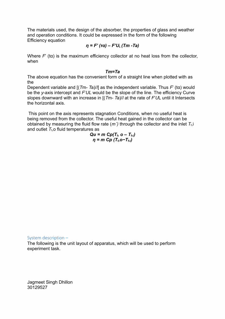
The materials used, the design of the absorber, the properties of glass and weatherand operation conditions. It could be expressed in the form of the followingEfficiency equation
η = F’ (τα) – F’UL (Tm -Ta)
Where F’ (tα) is the maximum efficiency collector at no heat loss from the collector,when
Tm=TaThe above equation has the convenient form of a straight line when plotted with as theDependent variable and [(Tm- Ta)/I] as the independent variable. Thus F’ (tα) would be the y-axis intercept and F’UL would be the slope of the line. The efficiency Curve slopes downward with an increase in [(Tm- Ta)/I at the rate of F’UL until it Intersects the horizontal axis.
This point on the axis represents stagnation Conditions, when no useful heat is being removed from the collector. The useful heat gained in the collector can be obtained by measuring the fluid flow rate (m˙) through the collector and the inlet Tf,i and outlet Tf,o fluid temperatures as
Qu = m Cp(Tf, o – Tf,i)η = m Cp (Tf,o−Tf,i)
System description – The following is the unit layout of apparatus, which will be used to perform experiment task.
Jagmeet Singh Dhillon30129527

(G.U.N.T, HL 313 Single Solar(Instructional Manual) 2013)

Schematic Diagram of Flat plate solar water heater (M.S. Hossainb 2011)
Thermocouple wires are inserted at water collector inlet, water collector outlet, two positions in the storage tank, in addition to two other wires measuring ambient and collector back temperatures. A pyrometer is also installed to measure the total radiation at different tilt angles. For this analysis several sunny and cloudy days in winter were chosen. On each day, the total storage tank waterwas drained in the morning and refilled with clean tap water. Thermal collector, Direct and diffuse sunlight from the surrounding environment strikes an absorber and is converted into heat by the transfer of energy to, e.g., water molecules. To be able to reach temperatures and efficiencies that are as high as possible, the absorber is thermally insulated to the surrounding environment. To be able to absorb a large amount of sunlight, the thermal insulation at least on the front must be of transparent design. The heat generatedis fed to a load using a liquid or gaseous transfer system.
Although, most of the days in winter are cloudy in Ballarat. So some sunny days will be chosen to study the performance of system.
The flat plate collector will be tilted at some angle corresponding to the latitude of thelocation at Mount Helen campus (Federation University Australia). The temperature of the different locations can be measured, using PT-100 RTD sensors. The solar radiation was measured on the plane of the solar collector using a pyrometer
Jagmeet Singh Dhillon30129527

(Available in campus laboratory); the ambient temperature and the wind speed were measured using prescribed laboratory equipment’s. All the sensors will be connected to a data acquisition system, will record every 5 min continuously and plotted in graphs. A booster pump can be used during forced circulation testing.
HIRAC Report- The following HIRAC report has been prepared as safety measure to perform experiment.
HIRAC ReportRisk, Health and Safety
This form relates to OHS Procedure – Hazard Identification, Risk Assessment andControl (HIRAC)
Date: 26/04/2016
Plant, Building, Task, Activity, Item Description:
Solar hot water system
Campus: Mount Helen School/ Section: SEIT
HIRAC conducted by
Jagmeet Singh Dhillon Email: [email protected]
HAZARD DESCRIPTIONRISKASSESSED
CONTROL MEASURE(S)WHO / WHEN
DATECOMPLETED
Biomechanical and Postural
Very low I will not have to lift any heavy objects when I am conducting my experiments. The rig I am using is on wheels.
Jagmeet
Physical Environment Very low Drain tank in case of risk of frost.
Secure system and solar collectors in case of storm (tie down).
Jagmeet
Mechanical No assessable risk
The apparatus has no exposedmoving parts or mechanical hazards.
However, appropriate footwearwill be worn whilst I am conducting my experiments and whenever I am in the lab.
Jagmeet
Electrical
Electric shock
Low Prior to working on the electrical system, switch off main switch and unplug apparatus from the mains.
Jagmeet

If need be, work on the electrical system is only to be performed by suitably qualified personnel ONLY.
Protect the electrical system from moisture and splashes.
Chemicals and Toxicity Low Heat transfer fluid contains glycol sealed in heat pipes andsolar collector. Occasional skincontact with this liquid is not hazardous
Will certainly avoid contact withthe eyes in case of leakage.
Jagmeet
Biological and Human risk No assessable risk
The apparatus has no biological or human hazards
Risk of Burns Low Heat transfer fluid and pipes can in good solar conditions reach 100°C. Heat pipes are mostly insulated but I will avoidcontact with heat pipes and any other hot surfaces.
Jagmeet
Public Place Low As this experiment will be donein public walkway outside Y-building and electric cables willbe used.
As precaution measures, signage or cones are required to alert the public that experiment is in progress.
Jagmeet
Design of Experiment –The experiment for data collection will be done with Muzamal, because he is also working
on same apparatus, but our focus be different as Muzamal is investigating on the effect
of air velocity and my exploration relates to effect of flow rate.
It would be better to work as a team to collect data.
Description of the Projects:Muzamal’s project: The effect of air velocity on the performance of the Solar
Thermal Collector at different operating conditions.
Independent factors are:
I. Velocity of air flowing past (3 levels).
II. Tilt angle (3 levels)
III. Atmospheric conditions (noise – just recorded)
Jagmeet Singh Dhillon30129527

IV. Illuminance (3 levels)
Dependent variables:
I. Heat acquired from light source to the hot fluid
II. Heat transferred to the cold fluid
III. Efficiency
Experimental strategy if adequate time is available: 3x3x3
NOTE: IF WORKING INDOORS FIX DISTANCE TO LIGHT SOURCE AND
FIX THE HORIZONTAL ORIENTATION. RECORD THESE VALUES AND
USE THEM TO PISTION THE COLLECTOR AT EVERY EXPERIMENT
Jagmeet’s project: The effect of flow rates on the performance of solar
collectors at different operating conditions.
Independent factors:
1. Flow rate of cold fluid (3 levels)
2. Flow rate of hot fluid (3 levels)
3. Cold water temperature(Inlet and outlet)
4. Hot water temperature (Inlet and outlet)
5. Atmospheric conditions (noise – just recorded)
6. Illuminance (3 levels)
Dependent variables:
I. Heat acquired from light source to the hot fluid
II. Heat transferred to the cold fluid
III. Efficiency
Experimental strategy if adequate time is available: 3x3x3
NOTE: TAKE THE MEASUREMENTS WHICH CORRESPOND TO ONE AIR
VELOCITY SITTINGS DONE BY MUZAMAL
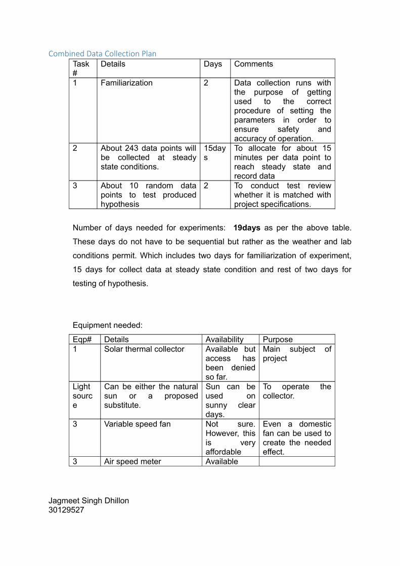
Combined Data Collection PlanTask#
Details Days Comments
1 Familiarization 2 Data collection runs withthe purpose of gettingused to the correctprocedure of setting theparameters in order toensure safety andaccuracy of operation.
2 About 243 data points willbe collected at steadystate conditions.
15days
To allocate for about 15minutes per data point toreach steady state andrecord data
3 About 10 random datapoints to test producedhypothesis
2 To conduct test reviewwhether it is matched withproject specifications.
Number of days needed for experiments: 19days as per the above table.
These days do not have to be sequential but rather as the weather and lab
conditions permit. Which includes two days for familiarization of experiment,
15 days for collect data at steady state condition and rest of two days for
testing of hypothesis.
Equipment needed:
Eqp# Details Availability Purpose1 Solar thermal collector Available but
access hasbeen deniedso far.
Main subject ofproject
Lightsource
Can be either the naturalsun or a proposedsubstitute.
Sun can beused onsunny cleardays.
To operate thecollector.
3 Variable speed fan Not sure.However, thisis veryaffordable
Even a domesticfan can be used tocreate the neededeffect.
3 Air speed meter Available
Jagmeet Singh Dhillon30129527

This brief document presents a data collection plan for the Master by course
work projects of Muzamal and me. An estimate has been made as to the
number of days needed to run the experiments and as to the equipment
required for the projects.
Me and my mate Muzamal (Mentioned above) doing our Research project on
same topic and we will use same apparatus but our concern is different. As
mentioned above, Muzamal is pursuing his research on effect of air velocity
on the performance of the Solar Thermal Collector at different operating
conditions. Whereas, my exploration is based on the effect of flow rates on
the performance of solar collectors at different operating conditions.

6. TIMELINE FOR PROPOSED WORK
As this project is required to be completed by the November 2016 but due to hinders
in experiment, now it is need to complete by January 2017. So accordingly I have
planned to undertake this study and break this study into number of tasks so that
every tasks can be completed within time. As this does not require any experimental
investigations but still I have to undertake lot reading of collect the data for effected
properties and to know reasons for their change. In the end I need to develop a
common strategy for effect of flow rate setting on desired solar heating system so
that more effective results can be obtained.
The following GANT chart was generated with the help of Minitab.
Figure 15/ GANT chart representing the time schedule for different tasks
Jagmeet Singh Dhillon30129527

7. TABLE OF CONTENTS FOR THESIS WRITING -
8. REFERENCESA.A. Karaghouli a, *, W.E. Alnaser b. 2001. “Experimental study on thermosyphon
solar.” Renewable Energy 389-396.Al-Madani, Hussain. 2006. “The performance of a cylindrical solar water heater.”
Renewable energy 1751-1763.canada, Health. 2013. Statement of the Science Report for Ethylene Glycol.
Accessed June 24, 2013. http://www.hc-sc.gc.ca/ewh-semt/pubs/contaminants/psl2-lsp2/ethylene_glycol/index-eng.php#a2436.
Christopher J. Koroneos a, *, Evanthia A. Nanaki b. 2012. “Life cycle environmental impact assessment of a solar water heater.” Production of cleaner energy 154-161.
Davabkhaktuni, V., Alam, M., Depuru, S.S. S. R., Green, R. C., Nims. 2013. “ Solar energy: Trends and enabling technologies.” Renewable and sustainable Energy review 555-564.
Feng Shan, Lei Cao, Guiyin Fang,. 2013. “Dynamic performances modeling of a photovoltaic–thermal collector with water heating in buildings.” Energy and buildings 485-494.
G.U.N.T. May, 2013. “Domestic water heating with flat plat collector.” Energy and Enviornment.
G.U.N.T. 2013. “HL 313 Single Solar(Instructional Manual).” Instruction Manual, Barsbuttel, Germany.
HC. 2013. Statement of the Science Report for Ethylene Glycol. 24 June. http://www.hc-sc.gc.ca/ewh-semt/pubs/contaminants/psl2-lsp2/ethylene_glycol/index-eng.php#a2436.
Jee Joe Michael, S. Iniyan. 2015. “Performance of copper oxide/water nanofluid in a flat plate solar water.” Energy conversion and Management 160-169.
K. Sampathkumar, P. Senthilkumar. 2012. “Utilization of solar water heater in a singlebasin solar still—An experimental study.” Desalination 8-19.
M. Boubekri a, A. Chaker a, A. Cheknane b,⁎. 2013. “Modeling and simulation of the continuous production of an improved.” Desalination 6-15.
M.S. Hossainb, ∗, R. Saidura,b, H. Fayazb, N.A. Rahimb, M.R. Islama, J.U.
Ahameda, M.M. Rahmanb. 2011. “Review on solar water heater collector and thermal energy performance of circuylating pipe.” Renewable and SustainableEnergy Reviews 3801-3811.
manufacturar, solar hot water and heating. 2015. Sun max solar. http://www.sunmaxxsolar.com/evacuated tube solar water heating.

Mobin Arab, Ali Abbas. 2013. “Model-based design and analysis of heat pipe workingfluid for.” Solar energy 162-176. Accessed 2013.
P.V. Durga Prasad a, ⇑, A.V.S.S.K.S. Gupta b, M. Sreeramulu b, L. Syam Sundar c,
M.K. Singh c,. 2015. “Experimental study of heat transfer and friction factor of Al2O3 nanofluid.” Experimental Thermal and Fluid Science 62 141-150.
parts, Machine. 2013. Mechanism for solar collector for flat plate. sunday june. Accessed 2013. http://newmachineparts.blogspot.com.au/2013/06/mechanism-of-solar-collector-for-flat.html.
Raouf Benrejeb, Olfa Helal, Bechir Chaouachi. Feb, 2015. “Optical and thermal performances improvement of an ICS solar water heater system.” solar energy 108-119.
T. Rajaseenivasan a, P. Nelson Raja a, K. Srithar b. 2014. “An experimental investigation on a solar still with an integrated flat.” Desalination 131-137.
Trad Abderachid, Kaabi Abdenacer. 2012. “Effect of orientation on the performance of a symmetric solar still with a.” Elsevier 68-77.
Zhu, J., & Cui, Y. 2010. “ Photovoltaic: More solar cells for less.” Natural material 183-184.
Jagmeet Singh Dhillon30129527