progress of the apex experiment for creation of an...
TRANSCRIPT

Progress of the APEX Experiment for Creation of anElectron-Positron Pair Plasma
Uwe Hergenhahn1,2, Juliane Horn-Stanja1,a), Stefan Nissl1,3, Thomas SunnPedersen1, Haruhiko Saitoh1,4, Eve V. Stenson1, Matthew R. Stoneking5, Marcel
Dickmann3, Christoph Hugenschmidt3, Markus Singer3, James R. Danielson6 andClifford M. Surko6
1Max Planck Institute for Plasma Physics, Greifswald and Garching, Germany2Leibniz Institute of Surface Modification, Permoserstr. 15, 04318 Leipzig, Germany
3FRM II and Physics Department E21, Technische Universitat Munchen, 85747 Garching, Germany4The University of Tokyo, Kashiwa, Japan5Lawrence University, Appleton, WI, USA
6Department of Physics, University of California, San Diego, La Jolla, CA 92093-0319, USA
a)Corresponding author: [email protected]
Abstract. Electron-positron pair plasmas are an unexplored state of matter predicted to have properties intriguing for plasmaphysics as well as astrophysics. Here we described recent progress in the APEX collaboration dedicated to the production ofa cold, confined electron-positron plasma in the laboratory. We focus on methods to inject positrons produced externally into amagnetic dipole trap, and to manipulate the ensuing trapped positron cloud. These experiments are carried out at the NEPOMUCpositron beamline of the FRM II research reactor. Recent progress in producing more intense positron beams is briefly discussed.
INTRODUCTION
Experimenting with a confined electron-positron pair plasma is a vision that has fascinated plasma physicists foralmost fourty years [1]. Since the first publication of a realistic plan to produce such plasmas [2], substantial progresshas been made towards realization of this aim. In the APEX (A Positron-Electron plasma eXperiment) collaboration,we are working on a refined version of the aforementioned plan for pair plasma production (see [3]). Here we give anoverview on our recent experimental results.
In contrast to many non-neutral, i.e. single-component plasmas, a pair plasma, having charge carriers of bothsign, cannot be stored in a single linear particle trap. Nesting traps for species of opposite sign has been successful[4], but leaves the species in separate spatial regions of the traps or at different temperature. One configuration thathas the promise of storing a plasma at any degree of neutrality is the magnetic dipole field of a current loop freelyfloating in space. Levitation of the current loop is vital to avoid particle losses on the supporting structure. In previousexperiments, confinement of conventional (electron-ion) plasmas [5, 6] as well as pure electron plasmas [7] in thefield of a levitated, superconducting ring conductor has been achieved.
Having a sufficiently intense source for positrons is another essential for the creation of an electron-positronplasma. The NEPOMUC positron beam line at the FRM II research reactor in Munich, Germany, will be used inour experiments [8]. Injecting the positron beam from NEPOMUC into our trapping geometry is a non-trivial task.In order to test injection strategies, we have constructed a mock-up device consisting of a permanent magnet thatproduces a dipole field and is surrounded by an electrode structure [9]. Important points to be addressed in this deviceinclude the following:
• achieving sufficient cross field transport to interface the NEPOMUC beam line to the trapping volume,• manipulating the trapped positron cloud, e.g. to enable compression to a high-density state, and
Non-Neutral Plasma Physics XAIP Conf. Proc. 1928, 020004-1–020004-11; https://doi.org/10.1063/1.5021569
Published by AIP Publishing. 978-0-7354-1620-8/$30.00
020004-1
• understanding the trapping time and the underlying loss mechanisms.
In this contribution we will report about our progress with respect to these points. Accompanying the experiments,we have carried out extensive simulations of trajectories on the single particle level, which have greatly improved ourinsight into the injection mechanism. A general overview about earlier activities of the group has been given in [10].
Our group has also been active in characterizing the NEPOMUC positron beam with respect to, e.g., its intensityand energy components parallel and perpendicular to the magnetic guiding field [11]. Some results arrived at afterpublication of [11] are in the following section.
PROPERTIES OF THE PRIMARY NEPOMUC BEAM
The positron beam of NEPOMUC is produced from pair production in Pt foils, which at the same time act as positronmoderator [8]. The actual beam energy is set by a bias potential applied to the Pt foil structure and the subsequentbeam tube, which previously was chosen between 400-1000 V for most experiments. In order to increase the beambrightness, the ensuing ‘primary’ positron beam can be remoderated on a tungsten crystal in reflection geometry,which decreases its energy spread and spatial dimensions, however at the expense of a reduction in particle flux.Initial results reported by our group on injection of positrons into a dipole field also used this ‘remoderated’ beam [9].
As absolute number of (low-energy) positrons is the most decisive figure for our intended experiment, we haveworked on transporting a low-energy primary beam to the open beam port of the NEPOMUC user platform. For easydiagnosis of the beam intensity and profile, we have mounted a retractable microchannel plate (MCP) detector incombination with a fluorescence screen upstream of our injection experiment. (This detector is now at the position ofretractable metal plates, ‘x-y target’, used in our earlier work [11] to measure spatial beam extension.) As an alternativeto the MCP, a copper electrode for measuring the absolute positron current can be connected to a charge-integratingamplifier (operational amplier AD820 with a 4.7-nF feedback capacitor).
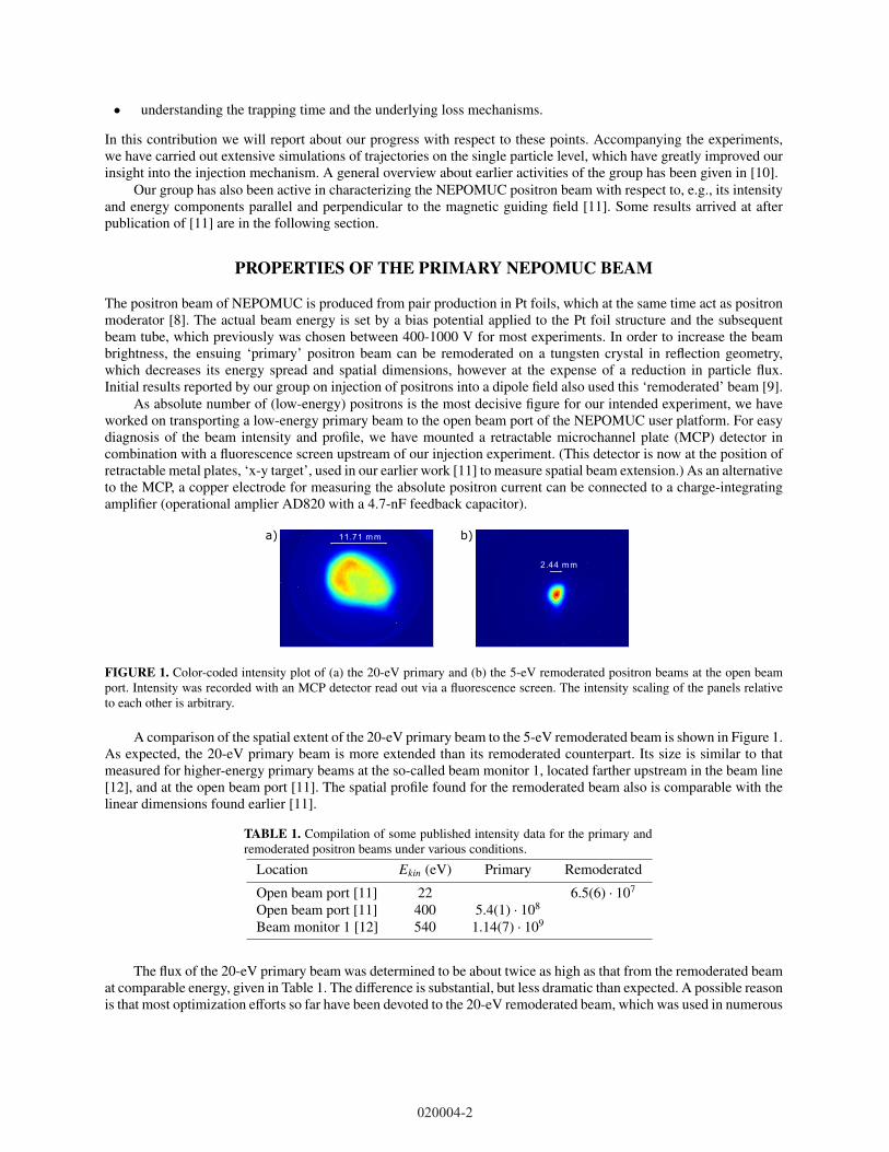
11.71 m ma) b)
2.44 m m
FIGURE 1. Color-coded intensity plot of (a) the 20-eV primary and (b) the 5-eV remoderated positron beams at the open beamport. Intensity was recorded with an MCP detector read out via a fluorescence screen. The intensity scaling of the panels relativeto each other is arbitrary.
A comparison of the spatial extent of the 20-eV primary beam to the 5-eV remoderated beam is shown in Figure 1.As expected, the 20-eV primary beam is more extended than its remoderated counterpart. Its size is similar to thatmeasured for higher-energy primary beams at the so-called beam monitor 1, located farther upstream in the beam line[12], and at the open beam port [11]. The spatial profile found for the remoderated beam also is comparable with thelinear dimensions found earlier [11].
TABLE 1. Compilation of some published intensity data for the primary andremoderated positron beams under various conditions.
Location Ekin (eV) Primary Remoderated
Open beam port [11] 22 6.5(6) · 107
Open beam port [11] 400 5.4(1) · 108
Beam monitor 1 [12] 540 1.14(7) · 109
The flux of the 20-eV primary beam was determined to be about twice as high as that from the remoderated beamat comparable energy, given in Table 1. The difference is substantial, but less dramatic than expected. A possible reasonis that most optimization efforts so far have been devoted to the 20-eV remoderated beam, which was used in numerous
020004-2

other positron experiments. Compared to positron flux measured for higher-energy primary beams at various locations(Table 1) we find a reduction of up to 89%. This seems to indicate that losses occur both because of the lower energy,possibly resulting in less efficient take-off of positrons from the Pt primary moderator into the beam line, as well asby non-adiabatic transport to the open beam port via three beam switches.
POSITRON INJECTION INTO A MAGNETIC DIPOLE FIELD
Experiment Geometry
sideview
collimated BGOview
ring electrode
positrons
shieldplate
ExBplates
magnettarget
viewing angleBGO
topview
1
2
3
4
5
6
7
8
shieldplate
ExB -
ExB +
target
a) b)
FIGURE 2. Sketch of the permanent magnet (center) and electrode arrangement to test injection of the NEPOMUC positron beaminto a dipole field and manipulation of the injected positron cloud: (a) sideways view and (b) seen from top. Note the displacementbetween the axis of the NEPOMUC open beam port (pointing vertically downward, red arrow) and the central axis of the magnet.Intersecting the toroidal precession of positrons around the magnet, a target probe (horizontally oriented, grounded stainless steelplate, 1×1 cm) can be inserted via a feedthrough on the opposite side of the nominal point of injection. Positron annihilation on thetarget probe is monitored by a scintillation detector (BGO, see panel b). In order to increase specificity of the signal, its viewingangle is collimated by lead bricks to the shaded region. In earlier versions of this arrangement, electrode segments 1-8 were pair-wise connected (1-2, 3-4, . . . ) and extended up to the area now taken up by the separate, ring-shaped top electrode (‘configurationA’), or were all at the same potential (‘configuration 0’) [9]. The configuration shown here will be referred to as ‘B’.
A report about our first experiments with injecting positrons into the field of a magnetic dipole has been given[9]. Here we describe more recent results obtained after that publication. The geometry of our set-up, previouslydetailed in [9], is shown in Figure 2. It consists of a cylindrical permanent magnet with a field strength of 0.6 T atthe pole faces, enclosed in a Cu housing. This magnet produces a dipole field with a vertical axis. The housing andthe magnet support (shown in Figure 2a) can be set to a bias voltage Umag. Slightly displaced from the central axisof the magnet, the NEPOMUC positron beam enters from above, passing between a pair of rectangular electrodes.Typically, as indicated in Figure 2b, the plates are set to voltages UE×B,−UE×B of equal absolute value but oppositesign, in order to avoid a net electrostatic acceleration or deceleration of the beam. The directions of the electric andmagnetic fields between the plates are such that an E × B-drift transports the positrons across magnetic field lines.For suitably chosen potentials, some positrons are able to enter a region of the magnetic dipole field in which theyare trapped by magnetic mirroring when moving towards the poles of the magnet. This leads to an up-down bouncemovement of the positrons, to which a much slower precession in the equatorial direction around the magnet is added[9].
In order to manipulate the positron cloud precessing around the magnet, a cylindrical electrode set (bias voltagesUseg1−8) has been mounted along the edge of the vacuum vessel. Over the course of our experiments its arrangementhas evolved; the most recent configuration is shown in Figure 2, and for the sake of discussion will be referred toas ‘B’. Two simpler arrangements of the electrodes are not explicitly shown, but points in which they differ from
020004-3

the Figure are explained in the caption. Those will be referred to as ‘0’ and ‘A’. For the simplest configuration ‘0’,injection of positrons into the dipole field with an efficiency of 40 % was shown in [9], but understanding of theunderlying mechanism was incomplete, and an optimization strategy towards higher efficiencies remained unclear.
Particle Trajectory SimulationsIn order to make progress on these problems, we have carried out simulations of numerous injection conditions, andcompared them to the experimental outcomes. A very satisfactory agreement has been reached, as will be demon-strated by some examples.
In the current study, the density of the positron beam is sufficiently low to allow a treatment on a single particlebasis. This can be justified by an estimate of the positron density in the particle trap. As discussed in detail below,only a short bunch of particles from the Nepomuc beam is present in our trap at any time. Putting in some numbers(3 × 10⁷ e+/s, 100 µs bunch positron bunch length, trapping volume estimated by a hollow cylinder with h = 50 mm,ri = 30 mm, ro = 70 mm) leads to particle densities on the order of 5 cm−3. The Debye length associated withthis plasma would be on the order of 3.6 m, which is much larger than its linear dimension. This is another way ofsaying that kinetic effects are much more important than self-generated electric fields from the plasma (see [13]). Theproblem of simulating the positron trajectories therefore boils down to propagating a particle under the influence ofa static electromagnetic field. We have used the commercial software SIMION 8.1.1.32 [14] for this purpose. In thefollowing, we describe technical details of our simulations.
FIGURE 3. Typical simulated single particle trajectory, conditions: positron beam with 〈E‖〉 = 5.16 eV, 〈E⊥〉 = 0.78 eV; electrodevoltages UE×B = ±175 V, Umag = −15 V, Useg1−8 = +5.5 V. The particle trajectory during the first 1 µs of simulated flight time isdrawn in blue. The red trace at the bottom is a projection of the points where the particle trajectory intersects the equatorial plane.Contours are drawn to mark the edges of the vacuum vessel, the magnet and the E × B-plates.
Due to the lack of symmetry of the set-up, a fully three-dimensional geometry had to be simulated. To keep therequirements on core memory manageable, a grid with a mesh size of 1 mm was used. Particles were propagated bya fourth order Runge-Kutta scheme. The step size was set to 0.05 grid units, and could be further reduced under the
020004-4

control of SIMION in regions where strong acceleration occurred (T.Qual = 119). Sufficient numerical accuracywith these parameters was tested by simulating precession in a pure dipole field over 50 µs. Since SIMION is doing astraightforward calculation of the particle trajectories, it is numerically ineffective in regions with a strong magneticfield, in particular near to the permanent magnet. This is because a large number of tiny iteration steps is neededto simulate the cyclotron motion around the magnetic field lines, which has a gyroradius of typically 10-100 µm.As the gyroradius is smaller than any other relevant length scale of the problem, in principle the guiding centerapproximation [15] could be used to make calculations more effective. We are not aware of a code that implements itin arbitrary geometries, though. Some improvements in numerical efficiency (not covered here) were achieved recentlyby changing from SIMION’s Runge-Kutta scheme to an internally developed code using a symplectic integrator.
The simulation region encompassed the vacuum chamber housing the permanent magnet and the transfer elec-trodes. Its upper end is at the interface to a section of our apparatus used for beam diagnosis (see [9, 11]). The guidingfield of the NEPOMUC positron beam line is connected to the dipole trap by a pair of Helmholtz coils. For our simu-lations, the magnetic field was calculated from the coil parameters using analytical expressions for the field of a thincurrent loop (see e.g. [16]). The permanent magnet was modelled by applying the same expressions to an assembly ofcurrent loops mimicking the spatial dimensions of the magnet and the field on its pole face.
A remoderated positron beam with a nominal energy of 5 eV was simulated. For each simulation run, a startingposition in the z = 400 mm plane was fixed. The positron beam in that position was represented by a set of, typically,100 particles. Earlier, we found the remoderated beam is well characterized by independent distribution functions forthe perpendicular and the parallel energy [11]. Following this work, for the perpendicular energy E⊥ we have used aMaxwell-Boltzmann distribution according to
f (E⊥) =1
kBT⊥exp
(−
E⊥kBT⊥
), (1)
with a temperature parameter of T⊥ = 0.78 eV. For the parallel energy E‖ a Gaussian distribution was assumed,
f (E‖) =1
√2πσ‖
exp
−(E‖ − 〈E‖〉
)2
2σ2‖
, (2)
with a mean of 5.16 eV and a spread σ‖ that was set equal to T⊥. Initial energies for the particles were produced asrandom draws from these distribution functions. The parallel movement of the particle was aligned to the directionof the magnetic field at the starting point, and each particle was given a random gyration angle. The particles werepropagated one at a time.
Discussion of Injection ResultsA simulated trajectory is shown in Figure 3. Here, we have simulated the conditions chosen in our original work [9].It can clearly be seen how particles transit from guided flight in the transport field to a trapped bounce motion aroundthe magnet. For the sake of discussion, after 1 µs of simulated flight a particle is categorized as having been injectedinto the trapping field.
It is instructive to connect the particle motion to the topology of the magnetic field in our experiment. Towardsthis end, we have visualized the magnetic field lines as the iso-surfaces of the flux function Ψ(r). The followingexpression for the flux function of a thin current loop (radius a, center at (0, zc)), expressed in cylindrical coordinates,was used:
Ψ(r, z) := 2πrAφ = µ0I2k√
ar[(
1 −k2
2
)K(k) − E(k)
]. (3)
Here, Aφ is the vector potential, I is the current, K and E are complete elliptical integrals of the first and second kind,and k the abbreviation for k(r, z) = [4ar/((a + r)2 + (z − zc)2)]1/2.
In order to be trapped, the positrons have to transit from the system of open field lines originating at the source tothe system of closed dipole field lines around the magnet. A separatrix marking the division between the two systemsis plotted red in Figure 4, which shows that injection is accomplished by a combination of E × B-drift induced cross-field transport and magnetic mirroring. Note that the lower end of the E × B-electrodes is at z = 0.21 m. We also notethat the overlap of the dipole fields from Helmholtz coils and magnet lead to the occurrence of an X-point, which liesoutside of the region we have chosen for cross-field transport, however.
020004-5

-0.2 -0.1 0.0 0.1 0.2 0.3 0.4x (m)
0.0
0.1
0.2
0.3
0.4
0.5
0.6
z (m
)
FIGURE 4. Flux surface contours in the plane containing the magnet dipole vector and the central axis of the NEPOMUC guidingfield. The field of view contains the magnet at x = 0.1 m as well as Helmholtz coils for beam guiding. The blue trajectory shownin Figure 3 is projected onto this plane.
0 1 2 3 4 5E⊥ (eV)
3
4
5
6
7
E��(eV)
injectedt.probe(lost)
FIGURE 5. Injection as a function of the parallel and perpendicular energy of simulated trajectories, same conditions as in Figure3. Particles injected into the dipole field are drawn by a ‘+’-symbol, particles that are not injected by a triangle. Particles that makeat least a half turn around the magnet, thereby reaching the target probe, are additionally marked by an open circle.
The experimentally measured injection efficiency in [9] was found to be approx. 40 %. It was determined fromthe fraction of current measured on the target probe, compared to an electrode in the upstream section for beamanalysis. The fraction of simulated particles that reach the target probe was determined by post-processing of thetrajectories; electrostatic effects induced by insertion of the probe were thus neglected. For the ensemble shown inFigure 5, a fraction of 0.38 reaches the target probe, in good agreement with the experiment. Inspecting the particleenergies of the ensemble shows that injection mostly fails for particles with a low E⊥ (Figure 5). Moreover, particleswith insufficient E‖ may enter the dipole field region, but are not able to further precess around the magnet; in theseparticular injection conditions this is caused by the positive bias voltage on all wall electrodes.
020004-6
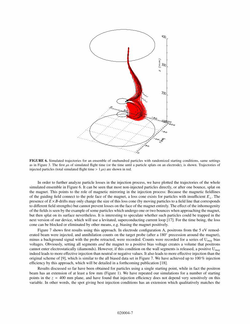
FIGURE 6. Simulated trajectories for an ensemble of onehundred particles with randomized starting conditions, same settingsas in Figure 3. The first µs of simulated flight time (or the time until a particle splats on an electrode), is shown. Trajectories ofinjected particles (total simulated flight time > 1 µs) are shown in red.
In order to further analyze particle losses in the injection process, we have plotted the trajectories of the wholesimulated ensemble in Figure 6. It can be seen that most non-injected particles directly, or after one bounce, splat onthe magnet. This points to the role of magnetic mirroring in the injection process: Because the magnetic fieldlinesof the guiding field connect to the pole face of the magnet, a loss cone exists for particles with insufficient E⊥. Thepresence of E×B-drifts may only change the size of this loss cone (by moving particles to a field line that correspondsto different field strengths) but cannot prevent losses on the face of the magnet entirely. The effect of the inhomogenityof the fields is seen by the example of some particles which undergo one or two bounces when approaching the magnet,but then splat on its surface nevertheless. It is interesting to speculate whether such particles could be trapped in thenext version of our device, which will use a levitated, superconducting current loop [17]. For the time being, the losscone can be blocked or eliminated by other means, e.g. biasing the magnet positively.
Figure 7 shows first results using this approach. In electrode configuration A, positrons from the 5 eV remod-erated beam were injected, and annihilation counts on the target probe (after a 180◦ precession around the magnet),minus a background signal with the probe retracted, were recorded. Counts were recorded for a series of Umag biasvoltages. Obviously, setting all segments and the magnet to a positive bias voltage creates a volume that positronscannot enter electrostatically (diamonds). However, if this condition on the wall segments is released, a positive Umagindeed leads to more effective injection than neutral or negative values. It also leads to more effective injection than theoriginal scheme of [9], which is similar to the all biased data set in Figure 7. We have achieved up to 100 % injectionefficiency by this approach, which will be detailed in a forthcoming publication [18].
Results discussed so far have been obtained for particles using a single starting point, while in fact the positronbeam has an extension of at least a few mm (Figure 1). We have repeated our simulations for a number of startingpoints in the z = 400 mm plane, and have found that injection efficiency does not depend very sensitively on thisvariable. In other words, the spot giving best injection conditions has an extension which qualitatively matches the
020004-7

-60 -40 -20 0 20 40 600
200
400
600
800
1000
1200
1400
1600
entire outer wallbiased to +7 V
magnet bias (V)
targ
etp
rob
ea
nn
ihila
tion
cou
nt(
pro
be
IN-
pro
be
OU
T)
V (seg 1,2) = +12 VV (seg 3-8) = 0 V
FIGURE 7. Counts on target probe for varying magnet bias. The wall electrodes either were biased all positively (diamonds), oronly 25 % of the wall, near the injection region, was biased (squares).
actual beam dimensions. (No causal relation between the two facts is known to us.)After somewhat more than a half revolution around the magnet, the simulated trajectory shown in Figure 3 ends
with a splat of the particle on one of the outer electrodes. (We note that the total energy of this selected particleis sufficient to reach the outer electrodes despite them being on a +5.5 V bias potential.) Obviously, this inhibitsparticle trapping over extended times. We have extensively investigated the cause of this effect, which is universal tothe particle ensemble and robust against variations of the electrode settings. It can be traced back to the electrostaticfringe field of the positively charged E × B-electrode, which leaks into the part of the trapping region pertaining toapprox. 270◦-330◦ of revolution around the magnet. No easy fix has occurred to us yet, as lowering the absolute valueof the E × B-voltage leads to less efficient injection, and increasing the particle energy requires an increase of theE × B-voltage as well. We therefore have conducted experiments on positron trapping times by injecting a bunch ofparticles, and subsequently switching out the E × B-voltage, as developed empirically in [9]. Some results on particletrapping are described in a later section of this report.
TRAPPED PARTICLE MANIPULATIONSome control on the trapped particle orbit is possible in the injection process; our results on this aspect will begiven elsewhere [18]. Here, we focus on methods to manipulate the positron cloud during precession around themagnet. For non-neutral plasmas stored in a Penning-Malmberg trap, compression of the plasma filament by AC fieldsapplied to a radially segmented electrode is very effective [19]. We have attempted to implement an analogue to these‘rotating wall’ (RW) fields in our set-up. To this end, sinusoidally varying voltages produced by a function generatorwere applied to the electrode segments shown in Figure 2. Segments were paired, as only four output channels wereavailable at the time of experiments. Between each pair of electrodes, a phase lag of π/2 was applied, so the fieldcirculated around the magnet. We will therefore call it a RW field, although the mechanism of its action (if any) hasto be different from RW fields in a Penning-Malmberg. While the latter injects torque into the rotating non-neutralplasma, the former instead induces an additional E × B-drift that may drive particles inward. These experiments usedan electrode configuration with the top ring set to 12 V.
In order to find whether these AC fields produce any effect, we have monitored annihilation counts on the targetprobe (Figure 8) for continuous injection of positrons into the trap in the presence of a RW field with variable fre-quency. These experiments were done in configuration B, using a magnet bias of Umag = −5 V and UE×B = ±230 V.The amplitude of the field was limited by the function generator. Using an oscilloscope we measured 14 V for frequen-cies up to 1.5 MHz, but lower amplitudes at higher frequencies, caused by the frequency response of the amplifiersused. The idea was to insert the target probe to a position where it intercepts the positron cloud, thus producing someamount of annihilation counts. If the annihilation rate decreases by application of the RW field, this could indicate aninward drive of the particles, which now pass the probe without annihilating.
In order to extract experimental information on the RW field effects from Figure 8, for each probe positionthe data measured with the field on (symbols) should be compared with the respective zeroline (dashed). For theoutermost probe position, a decrease is seen for all frequencies below 1 MHz. At more inward positions of the probe,
020004-8

100 101 102 103 104
frequency / kHz
0
50
100
150
200
250
coun
ts a
fter
back
gro
und
subt
ract
ion
2cm inserted3.5cm inserted5cm insertedt
Urw
t
t
t
1,23,4
5,67,8
a) b)
FIGURE 8. Effect of applying a rotating field to the electrodes around the trapping volume. a) Sketch of phase and waveformof the electric field. The oscillating field (‘RW field’) was applied continuously. Electrodes are seen from the top, and numberingof the segments refers to Figure 2. b) Annihilation counts on the target probe measured in the presence of a RW field. Data areshown vs. RW frequency for three different target positions, probing (from 2 to 5 cm insertion) gradually more central regions ofthe trapping volume. Insertion by 3.5 cm approximately corresponds to a ‘halfway in’ position; at 5 cm the full positron cloudshould be blocked. A background signal measured with retracted probe has been subtracted. Dashed lines give the respective signalwithout a RW field. See text for details.
an increase or a decrease in counts can be seen, depending on the frequency. Inward compression is also suggestedby the data measured at 3.5 cm for frequencies of one to several hundred kHz. The conclusion from this Figure isthat manipulation of the shape of the injected positron packets by a RW field is possible. For compression, the mostsuitable frequency range seems to be 150-200 kHz.
−1 0 1 2 3 4 5 6 7 8insert ion / cm
0
20
40
60
80
100
120
140
160
180
coun
tsaf
ter
back
grou
nd s
ubtr
actio
n
RW elect rodem agnet surface
CW, 150kHz@7V
CW, 150kHz@14V average
FIGURE 9. Annihilation counts on the target probe measured for two different amplitudes of a RW field, otherwise same conditionsas in Figure 8.
For a RW field with 150 kHz, we have recorded an extended set of annihilation counts vs. probe position data.Results for two different RW amplitudes are in Figure 9. Differences between the two settings are clearly visible(showing again that the fields have an effect), higher amplitude fields lead to a more efficient inward drive.
At the same time, however, in the plateau region where the probe blocks the full injected positron beam, fewerpositrons are observed for the higher field amplitude. We attribute this to an influence of the RW field on the injectionprocess itself, which may be constructive or detrimental. A similar finding is suggested by inspecting the 5-cm trace in
020004-9

Figure 8; for values of the frequency below some tens of kHz, we see an increase of positron counts despite Figure 9telling us that the probe already intercepts the full cloud. For this reason, we have refined our strategy by going to apulsed injection scheme, which allows a targeted use of short RW wave trains. These experiments are described in aseparate contribution in this volume [20].
TRAPPED ENSEMBLE LIFETIME
0 50 100 150 200 250 300 350delay t im e / m s
0
10
20
30
40
50
60
70
cou
nts
/40
00
it.
(o
ld)
47.57 m s (old)
43.62 m s (dum p, fast )
424.47 m s (dum p, long)
0
50
100
150
200
250
300
350
cou
nts
/40
00
it.
(d
um
p)
FIGURE 10. Lifetime of positron clouds trapped in our magnetic dipole field, measured by two different acquisition schemes (bluesymbols, referred to lhs axis and red symbols, referred to rhs axis). Data indicate the presence of two components, one short-lived,the other being present for hundreds of ms. See text for details.
The lifetime of the injected positron cloud is an essential parameter for our experiments on pair plasmas, as theconfinement of about 1010 positrons in our magnetic trap (together with the same amount of electrons) will be neededto plausibly fullfill the requirements for formation of an electron-positron plasma [3, 13]. (For the example of the 22-eV remoderated beam with intensity given above this corresponds to 154 s of prefectly efficient injection.) We havecontinued experiments in which we measure the lifetime of a short bunch of injected positrons; initial results measuredlifetimes of several ms (hundreds of toroidal precessions) [9]. In order to improve sensitivity of these measurements,we have changed the data acquisition scheme. In our first experiments, to measure a lifetime with an expected upperlimit of τ, a counting window with a temporal duration tw << τ was started after a delay time ∆t with respect to thestart of the trapping phase; ∆t was then scanned. To acquire usable statistics, acquisition for each ∆t had to be iteratedseveral thousand times. The shortcoming of this scheme, which was initially dictated by the electronics componentsavailable to us, is that only a fraction of each period τ is used for data acquisition. Instead of detecting the positronslost during the confinement phase, we now dump the positron cloud after a delay time ∆t ≤ τ and record the amount ofpositrons left in the trap. This lead to a greatly improved signal-to-noise ratio for a given wall-clock time of positronbeam availability.
In Figure 10, data acquired with the old and new schemes are compared. These experiments were done in config-uration B, using a magnet bias of Umag = 5 V, UE×B = ±190 V, Utop = 16 V and Useg1−8 = 0 V. The new acquisitionscheme clearly revealed the presence of two fractions of positrons in the trapped particle cloud, one with a lifetime—for the electrode configuration probed here—of approx. 44 ms, and another that is far more long-lived (lifetime about424 ms). Although these results are yet not sufficient to readily produce a pair plasma, we consider them extremelyencouraging.
SUMMARY AND OUTLOOKEn route to the production of a cold, magnetically confined electron-positron plasma, we have systematically studiedthe injection of a positron beam from a reactor based source into a magnetic dipole geometry. A comparison ofexperiments with trajectory simulations lead us to a good understanding of the factors that are decisive for efficient
020004-10

injection. In a proof-of-principle experiment an inward drive of the injected positrons due to their interaction with ACfields has been observed. Trapping of positrons with lifetimes in the hundreds of ms has been demonstrated. As thenext step in the evolution of this long-term project, we will now focus on magnetic trapping by the field of a levitated,superconducting current loop.
ACKNOWLEDGMENTS
This work is based upon experiments performed at the NEPOMUC instrument operated by FRM II at the HeinzMaier-Leibnitz Zentrum (MLZ), Garching, Germany. Funding by the Deutsche Forschungsgemeinschaft (Hu 978/15,Sa 2788/2) is gratefully acknowledged. UCSD would like to acknowledge support from the UCSD Foundation. EVSacknowledges a grant by the Helmholtz Postdoc-Programme.
REFERENCES
[1] V. Tsytovich and C. B. Wharton, Comments Plasma Phys. Control. Fusion 4, 91–100 (1978).[2] T. Sunn Pedersen, J. R. Danielson, C. Hugenschmidt, G. Marx, X. Sarasola, F. Schauer, L. Schweikhard,
C. M. Surko, and E. Winkler, New J. Phys. 14, p. 035010 (2012).[3] T. Sunn Pedersen, P. Helander, E. V. Stenson, U. Hergenhahn, H. Saitoh, J. Horn-Stanja, M. R. Stoneking,
J. R. Danielson, and C. M. Surko, “A new frontier in laboratory plasma- and astrophysics: electron-positronplasmas,” http://www-thphys.physics.ox.ac.uk/research/plasma/JPP/papers17/pedersen wp.pdf.
[4] H. Higaki, C. Kaga, K. Fukushima, H. Okamoto, Y. Nagata, Y. Kanai, and Y. Yamazaki, New J. Phys. 19, p.023016 (2017).
[5] A. C. Boxer, R. Bergmann, J. L. Ellsworth, D. T. Garnier, J. Kesner, M. E. Mauel, and P. Woskov, Nat. Phys.6, 207–212 (2010).
[6] Z. Yoshida, H. Saitoh, J. Morikawa, Y. Yano, S. Watanabe, and Y. Ogawa, Phys. Rev. Lett. 104, p. 235004(2010).
[7] H. Saitoh, Z. Yoshida, J. Morikawa, Y. Yano, N. Kasaoka, W. Sakamoto, and T. Nogami, “Stable confinementof electron plasma and initial results on positron injection in rt-1,” in NON-NEUTRAL PLASMA PHYSICSVIII: 10th International Workshop on Non-Neutral Plasmas (AIP Publishing, 2013) p. 63.
[8] C. Hugenschmidt, C. Piochacz, M. Reiner, and K. Schreckenbach, New J. Phys. 14, p. 55027 (2012).[9] H. Saitoh, J. Stanja, E. V. Stenson, U. Hergenhahn, H. Niemann, T. Sunn Pedersen, M. R. Stoneking, C. Pi-
ochacz, and C. Hugenschmidt, New J. Phys. 17, p. 103038 (2015).[10] E. V. Stenson, H. Saitoh, J. Stanja, H. Niemann, U. Hergenhahn, T. S. Pedersen, G. H. Marx, L. Schweikhard,
J. R. Danielson, C. M. Surko, and C. Hugenschmidt, AIP Conference Proceedings 1668, p. 040004 (2015),http://aip.scitation.org/doi/pdf/10.1063/1.4923117 .
[11] J. Stanja, U. Hergenhahn, H. Niemann, N. Paschkowski, T. Sunn Pedersen, H. Saitoh, E. V. Stenson, M. R.Stoneking, C. Hugenschmidt, and C. Piochacz, Nucl. Instrum. Methods A 827, 52–62 (2016).
[12] C. Hugenschmidt, H. Ceeh, T. Gigl, F. Lippert, C. Piochacz, M. Reiner, K. Schreckenbach, S. Vohburger,J. Weber, and S. Zimnik, Journal of Physics: Conference Series 505, p. 012029 (2014).
[13] E. V. Stenson, J. Horn-Stanja, M. R. Stoneking, and T. Sunn Pedersen, J. Plasma Phys. 83 (2017), doi:10.1017/S0022377817000022.
[14] D. Manura and D. Dahl, SIMION (R) 8.0 User Manual, Scientific Instrument Services, Inc., Ringoes, NJ08551 (2008), http://simion.com/manual/.
[15] T. Sunn Pedersen, “The guiding center approximation,” in Trapped Charged Particles (World Scientific (Eu-rope), 2016) Chap. Three,, pp. 55–80.
[16] R. A. Schill, IEEE Transactions on Magnetics 39, 961–967 (2003).[17] H. Saitoh, T. Sunn Pedersen, and the APEX Team, “A note on levitation techniques and parameter consid-
erations towards a compact superconducting levitated dipole experiment,” This Volume.[18] E. V. Stenson, T. Sunn Pedersen, and the APEX Team, “Near-lossless charged particle injection into a
magnetic dipole trap,” unpublished.[19] J. R. Danielson, D. H. E. Dubin, R. G. Greaves, and C. M. Surko, Rev. Mod. Phys. 87, 247–306 (2015).[20] H. Saitoh, J. Horn-Stanja, S. Nißl, E. V. Stenson, U. Hergenhahn, T. Sunn Pedersen, M. Singer, M. Dickmann,
C. Hugenschmidt, M. R. Stoneking, J. R. Danielson, and C. M. Surko, “Manipulation of positron orbits in adipole magnetic field with fluctuating electric fields,” This Volume.
020004-11