programming pic microcontrollers - electrical and...
TRANSCRIPT

PROGRAMMING PIC MICROCONTROLLERS

Install ET-PGMPIC USB
• Install the following two programs from the CD.
– .NET Framework (dotnetfx).
– PICkit2Setup.
• After installation, click on the icon below to start the program.

ET-PGMPIC USB
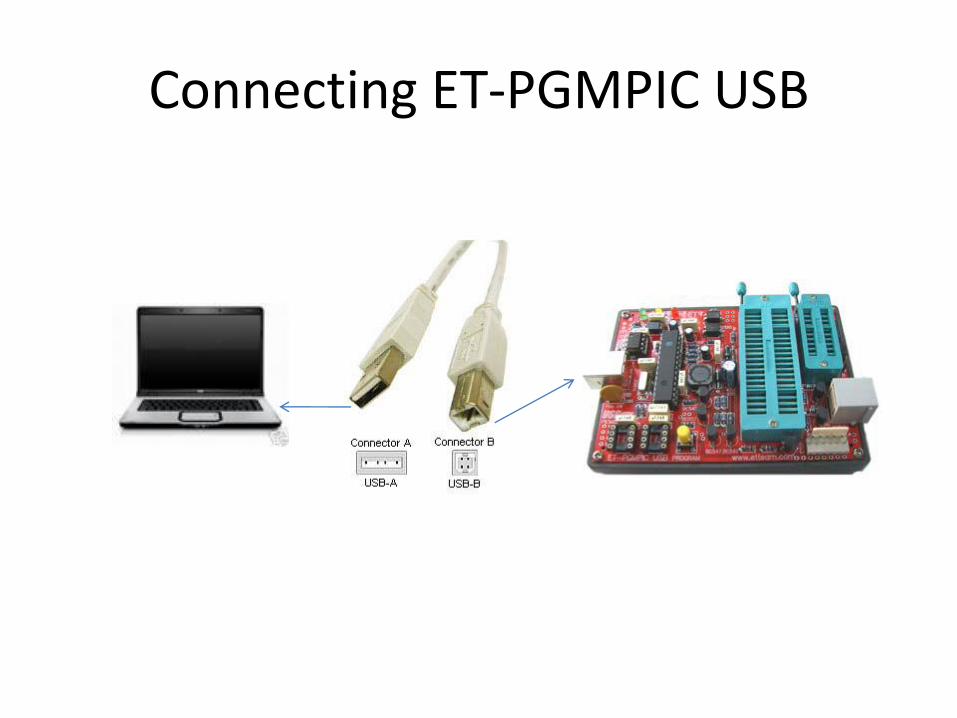
Connecting ET-PGMPIC USB

LED to display state operations
• BUSY: It is a red LED to display state operation of programmer. It will be ON when Program is running such as reading/writing Flash Memory of PIC microcontroller.
• TARGET: It is a yellow LED to display Power Supply status of Target Board.
• POWER: It is a green LED to display Power Supply status of Board.
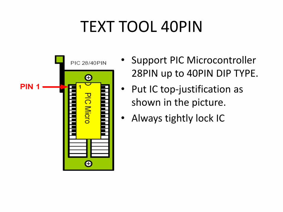
TEXT TOOL 40PIN
• Support PIC Microcontroller 28PIN up to 40PIN DIP TYPE.
• Put IC top-justification as shown in the picture.
• Always tightly lock IC

INTERFACING THROUGH ICD2
Interfacing signal from ET-PGMPIC USB and Emulation Module through Connector ICD2
ICD2 Interface
- Press to program. - Release to run
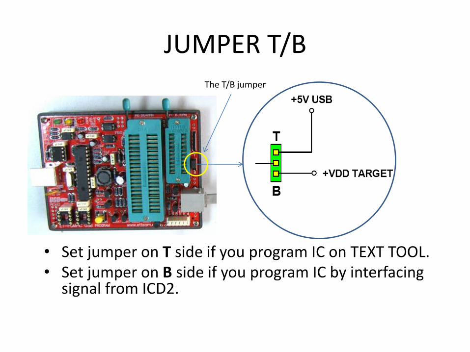
JUMPER T/B
• Set jumper on T side if you program IC on TEXT TOOL. • Set jumper on B side if you program IC by interfacing
signal from ICD2.
The T/B jumper
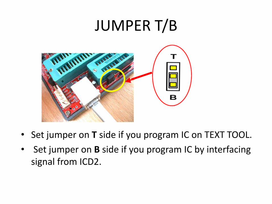
JUMPER T/B
• Set jumper on T side if you program IC on TEXT TOOL.
• Set jumper on B side if you program IC by interfacing signal from ICD2.

Switch PROGRAM
• Program by pressing Switch • This function can be used
by selecting [√] Write on PICkit Button from Programmer menu

Application of Software Program PICkit 2 Programmer
Configuration
PROGRAM Memory

MENU COMMANDS
• Import Hex- To load the appropriate hex file into Program PICkit2 for programming.
• Export Hex- To Export hex file that is read from Microcontroller for saving as file.

MENU COMMANDS
• PIC18F- To program with PIC18F Flash devices Microcontroller.
MENU COMMANDS
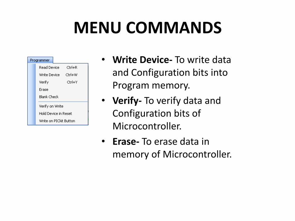
• Write Device- To write data and Configuration bits into Program memory.
• Verify- To verify data and Configuration bits of Microcontroller.
• Erase- To erase data in memory of Microcontroller.

METHODS TO PROGRAM
1. Use the USB Cable to connect your computer to the programmer (ET-PGMPIC USB).
2. Put the preferable IC PIC MCU into TEXT TOOL or Emulator Modules for programming.
• If programming on TEXT TOOL, SET Jumper T/B on T position.

METHODS TO PROGRAM • If programming on Target Board by Emulator
Module, set Jumper T/B on B position.
ET-PGMPIC USB
TARGET Board
T/B Jumper
METHODS TO PROGRAM
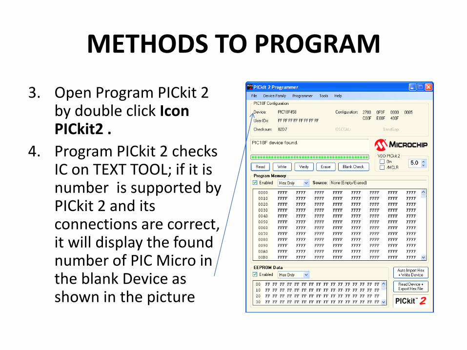
3. Open Program PICkit 2 by double click Icon PICkit2 .
4. Program PICkit 2 checks IC on TEXT TOOL; if it is number is supported by PICkit 2 and its connections are correct, it will display the found number of PIC Micro in the blank Device as shown in the picture
METHODS TO PROGRAM
5. Erase the old data in PIC Micro.
– Click Erase.
– The data in the blank Program Memory is FF.
6. Import Hex File as required, click menu command File -> Import Hex.
7. The data in the blank Program Memory is changed follow the loaded Hex File data.
METHODS TO PROGRAM
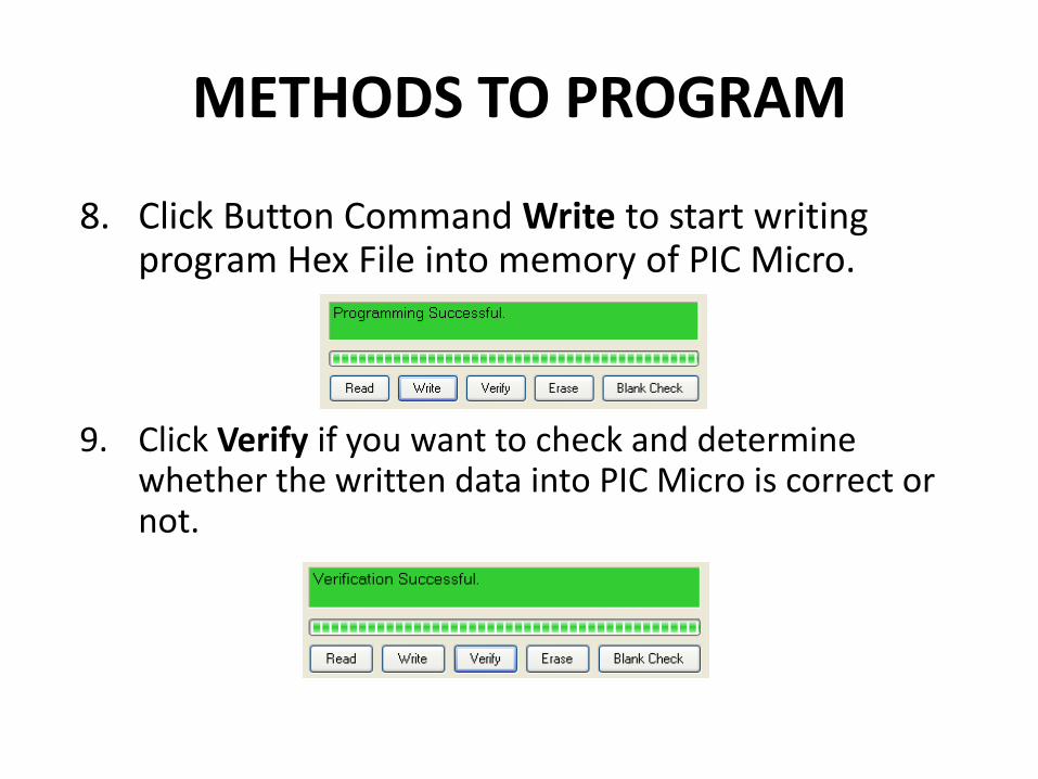
9. Click Verify if you want to check and determine whether the written data into PIC Micro is correct or not.
8. Click Button Command Write to start writing program Hex File into memory of PIC Micro.

PICDEM™ 2 PLUS DEMONSTRATION
BOARD USER’S GUIDE

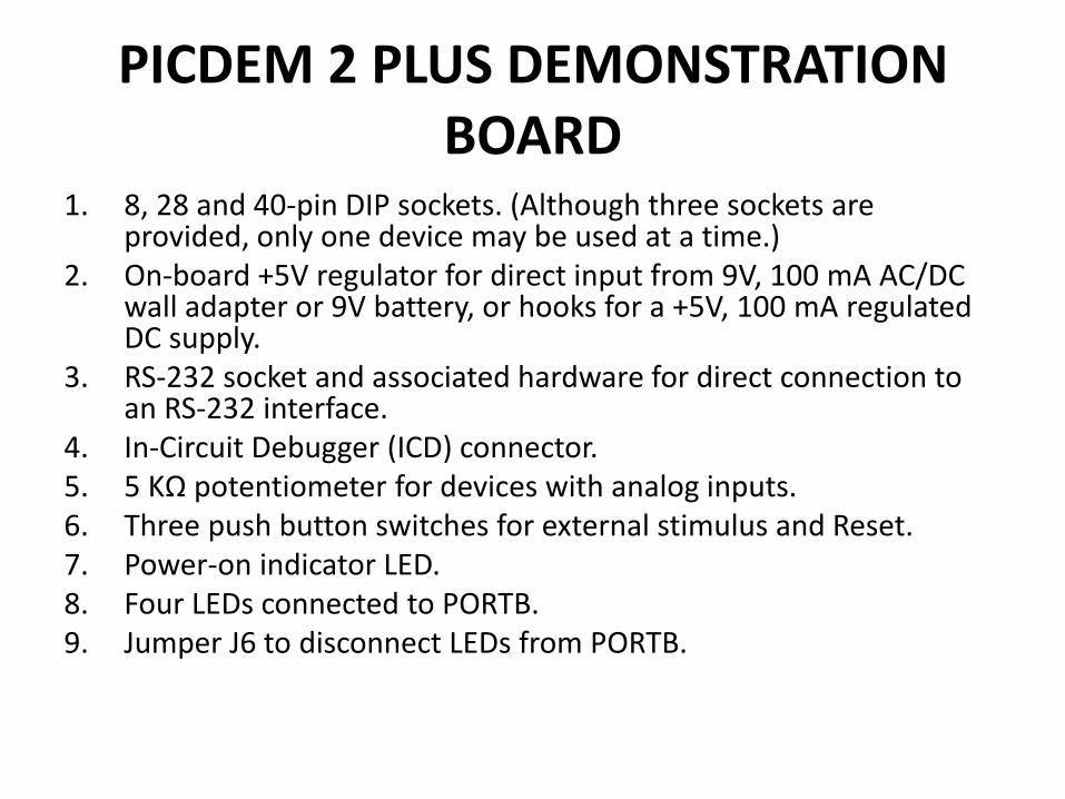
PICDEM 2 PLUS DEMONSTRATION BOARD
PICDEM 2 PLUS DEMONSTRATION BOARD
1. 8, 28 and 40-pin DIP sockets. (Although three sockets are provided, only one device may be used at a time.)
2. On-board +5V regulator for direct input from 9V, 100 mA AC/DC wall adapter or 9V battery, or hooks for a +5V, 100 mA regulated DC supply.
3. RS-232 socket and associated hardware for direct connection to an RS-232 interface.
4. In-Circuit Debugger (ICD) connector. 5. 5 KΩ potentiometer for devices with analog inputs. 6. Three push button switches for external stimulus and Reset. 7. Power-on indicator LED. 8. Four LEDs connected to PORTB. 9. Jumper J6 to disconnect LEDs from PORTB.

PICDEM 2 PLUS DEMONSTRATION BOARD
10. 4 MHz canned crystal oscillator.
11. Unpopulated holes provided for crystal connection.
12. 32.768 kHz crystal for Timer1 clock operation.
13. Jumper J7 to disconnect on-board RC oscillator (approximately 2 MHz).
14. 32K x 8 Serial EEPROM.
15. LCD display.
16. Piezo buzzer.
17. Prototype area for user hardware.
18. Microchip TC74 thermal sensor.
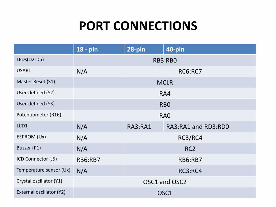
PORT CONNECTIONS
18 - pin 28-pin 40-pin
LEDs(D2-D5) RB3:RB0
USART N/A RC6:RC7
Master Reset (S1) MCLR
User-defined (S2) RA4
User-defined (S3) RB0
Potentiometer (R16) RA0
LCD1 N/A RA3:RA1 RA3:RA1 and RD3:RD0
EEPROM (Ux) N/A RC3/RC4
Buzzer (P1) N/A RC2
ICD Connector (J5) RB6:RB7 RB6:RB7
Temperature sensor (Ux) N/A RC3:RC4
Crystal oscillator (Y1) OSC1 and OSC2
External oscillator (Y2) OSC1