programmer’s guide - intel · april 2005 ixp400 software version 2.0 programmer’s guide 2...
TRANSCRIPT

Document Number: 252539, Revision: 007
Intel® IXP400 SoftwareProgrammer’s Guide
April 2005

April 2005 IXP400 Software Version 2.0 Programmer’s Guide2 Document Number: 252539, Revision: 007
Intel® IXP400 Software
INFORMATION IN THIS DOCUMENT IS PROVIDED IN CONNECTION WITH INTEL® PRODUCTS. EXCEPT AS PROVIDED IN INTEL'S TERMS AND CONDITIONS OF SALE FOR SUCH PRODUCTS, INTEL ASSUMES NO LIABILITY WHATSOEVER, AND INTEL DISCLAIMS ANY EXPRESS OR IMPLIED WARRANTY RELATING TO SALE AND/OR USE OF INTEL PRODUCTS, INCLUDING LIABILITY OR WARRANTIES RELATING TO FITNESS FOR A PARTICULAR PURPOSE, MERCHANTABILITY, OR INFRINGEMENT OF ANY PATENT, COPYRIGHT, OR OTHER INTELLECTUAL PROPERTY RIGHT.
Intel Corporation may have patents or pending patent applications, trademarks, copyrights, or other intellectual property rights that relate to the presented subject matter. The furnishing of documents and other materials and information does not provide any license, express or implied, by estoppel or otherwise, to any such patents, trademarks, copyrights, or other intellectual property rights.
Intel products are not intended for use in medical, life saving, life sustaining, critical control or safety systems, or in nuclear facility applications.
Intel may make changes to specifications and product descriptions at any time, without notice.
Designers must not rely on the absence or characteristics of any features or instructions marked “reserved” or “undefined.” Intel reserves these for future definition and shall have no responsibility whatsoever for conflicts or incompatibilities arising from future changes to them.
MPEG is an international standard for video compression/decompression promoted by ISO. Implementations of MPEG CODECs, or MPEG enabled platforms may require licenses from various entities, including Intel Corporation.
This document and the software described in it are furnished under license and may only be used or copied in accordance with the terms of the license. The information in this document is furnished for informational use only, is subject to change without notice, and should not be construed as a commitment by Intel Corporation. Intel Corporation assumes no responsibility or liability for any errors or inaccuracies that may appear in this document or any software that may be provided in association with this document. Except as permitted by such license, no part of this document may be reproduced, stored in a retrieval system, or transmitted in any form or by any means without the express written consent of Intel Corporation.
Contact your local Intel sales office or your distributor to obtain the latest specifications and before placing your product order.
Copies of documents which have an order number and are referenced in this document, or other Intel literature, may be obtained by calling1-800-548-4725, or by visiting Intel's website at http://www.intel.com.
BunnyPeople, Celeron, Chips, Dialogic, EtherExpress, ETOX, FlashFile, i386, i486, i960, iCOMP, InstantIP, Intel, Intel Centrino, Intel Centrino logo, Intel logo, Intel386, Intel486, Intel740, IntelDX2, IntelDX4, IntelSX2, Intel Inside, Intel Inside logo, Intel NetBurst, Intel NetMerge, Intel NetStructure, Intel SingleDriver, Intel SpeedStep, Intel StrataFlash, Intel Xeon, Intel XScale, IPLink, Itanium, MCS, MMX, MMX logo, Optimizer logo, OverDrive, Paragon, PDCharm, Pentium, Pentium II Xeon, Pentium III Xeon, Performance at Your Command, Sound Mark, The Computer Inside, The Journey Inside, VTune, and Xircom are trademarks or registered trademarks of Intel Corporation or its subsidiaries in the United States and other countries.
*Other names and brands may be claimed as the property of others.
Copyright © Intel Corporation 2005. All Rights Reserved.

Intel® IXP400 SoftwareContents
Programmer’s Guide IXP400 Software Version 2.0 April 2005Document Number: 252539, Revision: 007
Contents1 Introduction..................................................................................................................................19
1.1 Versions Supported by this Document ...............................................................................191.2 Hardware Supported by this Release .................................................................................191.3 Intended Audience..............................................................................................................191.4 How to Use this Document .................................................................................................201.5 About the Processors .........................................................................................................201.6 Related Documents ............................................................................................................211.7 Acronyms............................................................................................................................22
2 Software Architecture Overview ................................................................................................272.1 High-Level Overview...........................................................................................................272.2 Deliverable Model ...............................................................................................................282.3 Operating System Support .................................................................................................292.4 Development Tools.............................................................................................................292.5 Access Library Source Code Documentation .....................................................................292.6 Release Directory Structure................................................................................................302.7 Threading and Locking Policy.............................................................................................322.8 Polled and Interrupt Operation............................................................................................322.9 Statistics and MIBs .............................................................................................................322.10 Global Dependency Chart ..................................................................................................33
3 Buffer Management .....................................................................................................................353.1 What’s New.........................................................................................................................353.2 Overview.............................................................................................................................353.3 IXP_BUF Structure .............................................................................................................38
3.3.1 IXP_BUF Structure and Macros ............................................................................383.4 Mapping of IX_MBUF to Shared Structure .........................................................................433.5 IX_MBUF Structure.............................................................................................................443.6 Mapping to OS Native Buffer Types ...................................................................................46
3.6.1 VxWorks* M_BLK Buffer........................................................................................463.6.2 Linux* skbuff Buffer................................................................................................47
3.7 Caching Strategy ................................................................................................................493.7.1 Tx Path ..................................................................................................................493.7.2 Rx Path ..................................................................................................................503.7.3 Caching Strategy Summary...................................................................................50
4 Access-Layer Components:ATM Driver Access (IxAtmdAcc) API.........................................................................................534.1 What’s New.........................................................................................................................534.2 Overview.............................................................................................................................534.3 IxAtmdAcc Component Features........................................................................................534.4 Configuration Services........................................................................................................55
4.4.1 UTOPIA Port-Configuration Service ......................................................................554.4.2 ATM Traffic-Shaping Services ...............................................................................554.4.3 VC-Configuration Services ....................................................................................56
4.5 Transmission Services........................................................................................................57

Intel® IXP400 SoftwareContents
April 2005 IXP400 Software Version 2.0 Programmer’s Guide4 Document Number: 252539, Revision: 007
4.5.1 Scheduled Transmission ....................................................................................... 584.5.1.1 Schedule Table Description ................................................................... 59
4.5.2 Transmission Triggers (Tx-Low Notification) ......................................................... 604.5.2.1 Transmit-Done Processing .................................................................... 604.5.2.2 Transmit Disconnect .............................................................................. 62
4.5.3 Receive Services ................................................................................................... 634.5.3.1 Receive Triggers (Rx-Free-Low Notification)......................................... 644.5.3.2 Receive Processing ............................................................................... 644.5.3.3 Receive Disconnect ............................................................................... 66
4.5.4 Buffer Management ............................................................................................... 674.5.4.1 Buffer Allocation..................................................................................... 674.5.4.2 Buffer Contents ...................................................................................... 674.5.4.3 Buffer-Size Constraints .......................................................................... 694.5.4.4 Buffer-Chaining Constraints................................................................... 69
4.5.5 Error Handling........................................................................................................ 694.5.5.1 API-Usage Errors................................................................................... 694.5.5.2 Real-Time Errors.................................................................................... 70
5 Access-Layer Components:ATM Manager (IxAtmm) API ....................................................................................................... 715.1 What’s New......................................................................................................................... 715.2 IxAtmm Overview................................................................................................................ 715.3 IxAtmm Component Features............................................................................................. 715.4 UTOPIA Level-2 Port Initialization ...................................................................................... 725.5 ATM-Port Management Service Model............................................................................... 735.6 Tx/Rx Control Configuration ............................................................................................... 755.7 Dependencies..................................................................................................................... 775.8 Error Handling..................................................................................................................... 775.9 Management Interfaces ...................................................................................................... 775.10 Memory Requirements ....................................................................................................... 775.11 Performance ....................................................................................................................... 78
6 Access-Layer Components:ATM Transmit Scheduler (IxAtmSch) API ................................................................................. 796.1 What’s New......................................................................................................................... 796.2 Overview............................................................................................................................. 796.3 IxAtmSch Component Features.......................................................................................... 796.4 Connection Admission Control (CAC) Function.................................................................. 816.5 Scheduling and Traffic Shaping.......................................................................................... 82
6.5.1 Schedule Table...................................................................................................... 826.5.1.1 Minimum Cells Value (minCellsToSchedule)......................................... 836.5.1.2 Maximum Cells Value (maxCells) .......................................................... 83
6.5.2 Schedule Service Model ........................................................................................ 836.5.3 Timing and Idle Cells ............................................................................................. 84
6.6 Dependencies..................................................................................................................... 846.7 Error Handling..................................................................................................................... 856.8 Memory Requirements ....................................................................................................... 85
6.8.1 Code Size .............................................................................................................. 856.8.2 Data Memory ......................................................................................................... 85
6.9 Performance ....................................................................................................................... 856.9.1 Latency .................................................................................................................. 86

Intel® IXP400 SoftwareContents
Programmer’s Guide IXP400 Software Version 2.0 April 2005Document Number: 252539, Revision: 007
7 Access-Layer Components:Security (IxCryptoAcc) API .........................................................................................................877.1 What’s New.........................................................................................................................877.2 Overview.............................................................................................................................877.3 IxCryptoAcc API Architecture .............................................................................................88
7.3.1 IxCryptoAcc Interfaces...........................................................................................887.3.2 Basic API Flow.......................................................................................................897.3.3 Context Registration and the Cryptographic Context Database ............................907.3.4 Buffer and Queue Management ............................................................................937.3.5 Memory Requirements ..........................................................................................937.3.6 Dependencies........................................................................................................947.3.7 Other API Functionality ..........................................................................................957.3.8 Error Handling........................................................................................................967.3.9 Endianness ............................................................................................................967.3.10 Import and Export of Cryptographic Technology ...................................................96
7.4 IPSec Services ...................................................................................................................967.4.1 IPSec Background and Implementation ................................................................967.4.2 IPSec Packet Formats ...........................................................................................98
7.4.2.1 Reference ESP Dataflow .......................................................................997.4.2.2 Reference AH Dataflow .......................................................................100
7.4.3 Hardware Acceleration for IPSec Services..........................................................1017.4.4 IPSec API Call Flow.............................................................................................1017.4.5 Special API Use Cases........................................................................................103
7.4.5.1 HMAC with Key Size Greater Than 64 Bytes ......................................1037.4.5.2 Performing CCM (AES CTR-Mode Encryption and AES
CBC-MAC Authentication) for IPSec ...................................................1037.4.6 IPSec Assumptions, Dependencies, and Limitations...........................................106
7.5 WEP Services...................................................................................................................1067.5.1 WEP Background and Implementation................................................................1067.5.2 Hardware Acceleration for WEP Services ...........................................................1077.5.3 WEP API Call Flow ..............................................................................................108
7.6 SSL and TLS Protocol Usage Models ..............................................................................1107.7 Supported Encryption and Authentication Algorithms ......................................................111
7.7.1 Encryption Algorithms..........................................................................................1117.7.2 Cipher Modes ......................................................................................................112
7.7.2.1 Electronic Code Book (ECB)................................................................1127.7.2.2 Cipher Block Chaining (CBC) ..............................................................1127.7.2.3 Counter Mode (CTR) ...........................................................................1127.7.2.4 Counter-Mode Encryption with CBC-MAC Authentication (CCM)
for CCMP in 802.11i.............................................................................1127.7.3 Authentication Algorithms ....................................................................................113
8 Access-Layer Components:DMA Access Driver (IxDmaAcc) API........................................................................................1158.1 What’s New.......................................................................................................................1158.2 Overview...........................................................................................................................1158.3 Features............................................................................................................................1158.4 Assumptions .....................................................................................................................1158.5 Dependencies...................................................................................................................1168.6 DMA Access-Layer API ....................................................................................................116

Intel® IXP400 SoftwareContents
April 2005 IXP400 Software Version 2.0 Programmer’s Guide6 Document Number: 252539, Revision: 007
8.6.1 IxDmaAccDescriptorManager.............................................................................. 1188.7 Parameters Description .................................................................................................... 118
8.7.1 Source Address ................................................................................................... 1198.7.2 Destination Address............................................................................................. 1198.7.3 Transfer Mode ..................................................................................................... 1198.7.4 Transfer Width ..................................................................................................... 1198.7.5 Addressing Modes ............................................................................................... 1208.7.6 Transfer Length ................................................................................................... 1208.7.7 Supported Modes ................................................................................................ 121
8.8 Data Flow.......................................................................................................................... 1238.9 Control Flow...................................................................................................................... 123
8.9.1 DMA Initialization ................................................................................................. 1248.9.2 DMA Configuration and Data Transfer ................................................................ 125
8.10 Restrictions of the DMA Transfer...................................................................................... 1278.11 Error Handling................................................................................................................... 1288.12 Little Endian...................................................................................................................... 128
9 Access-Layer Components:Ethernet Access (IxEthAcc) API............................................................................................... 1299.1 What’s New....................................................................................................................... 1299.2 IxEthAcc Overview............................................................................................................ 1299.3 Ethernet Access Layers: Architectural Overview.............................................................. 130
9.3.1 Role of the Ethernet NPE Microcode................................................................... 1309.3.2 Queue Manager................................................................................................... 1319.3.3 Learning/Filtering Database................................................................................. 1319.3.4 MAC/PHY Configuration ...................................................................................... 131
9.4 Ethernet Access Layers: Component Features ................................................................ 1329.5 Data Plane........................................................................................................................ 133
9.5.1 Port Initialization .................................................................................................. 1349.5.2 Ethernet Frame Transmission ............................................................................. 134
9.5.2.1 Transmission Flow............................................................................... 1349.5.2.2 Transmit Buffer Management and Priority ........................................... 1359.5.2.3 Using Chained IX_OSAL_MBUFs for Transmission / Buffer Sizing .... 137
9.5.3 Ethernet Frame Reception................................................................................... 1379.5.3.1 Receive Flow ....................................................................................... 1389.5.3.2 Receive Buffer Management and Priority ............................................ 1399.5.3.3 Additional Receive Path Information.................................................... 142
9.5.4 Data-Plane Endianness ....................................................................................... 1439.5.5 Maximum Ethernet Frame Size ........................................................................... 143
9.6 Control Path...................................................................................................................... 1439.6.1 Ethernet MAC Control.......................................................................................... 145
9.6.1.1 MAC Duplex Settings........................................................................... 1459.6.1.2 MII I/O .................................................................................................. 1459.6.1.3 Frame Check Sequence ...................................................................... 1459.6.1.4 Frame Padding .................................................................................... 1459.6.1.5 MAC Filtering ....................................................................................... 1469.6.1.6 802.3x Flow Control ............................................................................. 1469.6.1.7 NPE Loopback ..................................................................................... 1479.6.1.8 Emergency Security Port Shutdown .................................................... 147
9.7 Initialization ....................................................................................................................... 1479.8 Shared Data Structures .................................................................................................... 147

Intel® IXP400 SoftwareContents
Programmer’s Guide IXP400 Software Version 2.0 April 2005Document Number: 252539, Revision: 007
9.9 Management Information..................................................................................................152
10 Access-Layer Components:Ethernet Database (IxEthDB) API.............................................................................................15510.1 Overview...........................................................................................................................15510.2 What’s New.......................................................................................................................15510.3 IxEthDB Functional Behavior............................................................................................155
10.3.1 MAC Address Learning and Filtering...................................................................15610.3.1.1 Learning and Filtering ..........................................................................15610.3.1.2 Other MAC Learning/Filtering Usage Models ......................................15810.3.1.3 Learning/Filtering General Characteristics...........................................158
10.3.2 Frame Size Filtering.............................................................................................16010.3.2.1 Filtering Example Based Upon Maximum Frame Size ........................161
10.3.3 Source MAC Address Firewall .............................................................................16110.3.4 802.1Q VLAN.......................................................................................................162
10.3.4.1 Background – VLAN Data in Ethernet Frames ....................................16310.3.4.2 Database Records Associated With VLAN IDs....................................16410.3.4.3 Acceptable Frame Type Filtering .........................................................16410.3.4.4 Ingress Tagging and Tag Removal......................................................16510.3.4.5 Port-Based VLAN Membership Filtering ..............................................16510.3.4.6 Port and VLAN-Based Egress Tagging and Tag Removal ..................16610.3.4.7 Port ID Extraction.................................................................................169
10.3.5 802.1Q User Priority / QoS Support ....................................................................16910.3.5.1 Priority Aware Transmission ................................................................16910.3.5.2 Receive Priority Queuing .....................................................................17010.3.5.3 Priority to Traffic Class Mapping ..........................................................171
10.3.6 802.3 / 802.11 Frame Conversion .......................................................................17210.3.6.1 Background — 802.3 and 802.11 Frame Formats...............................17210.3.6.2 How the 802.3 / 802.11 Frame Conversion Feature Works.................17410.3.6.3 802.3 / 802.11 API Details .................................................................176
10.3.7 Spanning Tree Protocol Port Settings .................................................................17710.4 IxEthDB API......................................................................................................................177
10.4.1 Initialization ..........................................................................................................17710.4.2 Dependencies......................................................................................................17710.4.3 Feature Set ..........................................................................................................17810.4.4 Additional Database Features .............................................................................178
10.4.4.1 User-Defined Field ...............................................................................17810.4.4.2 Database Clear ....................................................................................179
10.4.5 Dependencies on IxEthAcc Configuration ...........................................................17910.4.5.1 Promiscuous-Mode Requirement ........................................................17910.4.5.2 FCS Appending....................................................................................179
11 Access-Layer Components:Ethernet PHY (IxEthMii) API .....................................................................................................18111.1 What’s New.......................................................................................................................18111.2 Overview...........................................................................................................................18111.3 Features............................................................................................................................18111.4 Supported PHYs ...............................................................................................................18111.5 Dependencies...................................................................................................................182
Intel® IXP400 SoftwareContents
April 2005 IXP400 Software Version 2.0 Programmer’s Guide8 Document Number: 252539, Revision: 007
12 Access-Layer Components:Feature Control (IxFeatureCtrl) API ......................................................................................... 18312.1 What’s New....................................................................................................................... 18312.2 Overview........................................................................................................................... 18312.3 Hardware Feature Control ................................................................................................ 183
12.3.1 Using the Product ID-Related Functions ............................................................. 18412.3.2 Using the Feature Control Register Functions..................................................... 185
12.4 Component Check by Other APIs..................................................................................... 18612.5 Software Configuration .....................................................................................................18612.6 Dependencies................................................................................................................... 187
13 Access-Layer Components:HSS-Access (IxHssAcc) API..................................................................................................... 18913.1 What’s New....................................................................................................................... 18913.2 Overview........................................................................................................................... 18913.3 IxHssAcc API Overview.................................................................................................... 190
13.3.1 IxHssAcc Interfaces ............................................................................................. 19013.3.2 Basic API Flow..................................................................................................... 19113.3.3 HSS and HDLC Theory and Coprocessor Operation .......................................... 19213.3.4 High-Level API Call Flow ..................................................................................... 19513.3.5 Dependencies...................................................................................................... 19613.3.6 Key Assumptions ................................................................................................. 19613.3.7 Error Handling...................................................................................................... 197
13.4 HSS Port Initialization Details ........................................................................................... 19713.5 HSS Channelized Operation............................................................................................. 199
13.5.1 Channelized Connect and Enable ....................................................................... 19913.5.2 Channelized Tx/Rx Methods................................................................................ 201
13.5.2.1 CallBack............................................................................................... 20213.5.2.2 Polled ................................................................................................... 202
13.5.3 Channelized Disconnect ...................................................................................... 20413.6 HSS Packetized Operation ............................................................................................... 204
13.6.1 Packetized Connect and Enable.......................................................................... 20413.6.2 Packetized Tx ...................................................................................................... 20613.6.3 Packetized Rx...................................................................................................... 20813.6.4 Packetized Disconnect ........................................................................................ 21113.6.5 56-Kbps, Packetized Raw Mode.......................................................................... 211
13.7 Buffer Allocation Data-Flow Overview .............................................................................. 21113.7.1 Data Flow in Packetized Service ......................................................................... 21113.7.2 Data Flow in Channelized Service....................................................................... 214
14 Access-Layer Components:NPE-Downloader (IxNpeDl) API................................................................................................ 21914.1 What’s New....................................................................................................................... 21914.2 Overview........................................................................................................................... 21914.3 Microcode Images ............................................................................................................ 21914.4 Standard Usage Example................................................................................................. 22014.5 Custom Usage Example ................................................................................................... 22314.6 IxNpeDl Uninitialization..................................................................................................... 22314.7 Deprecated APIs............................................................................................................... 224

Intel® IXP400 SoftwareContents
Programmer’s Guide IXP400 Software Version 2.0 April 2005Document Number: 252539, Revision: 007
15 Access-Layer Components:NPE Message Handler (IxNpeMh) API .....................................................................................22515.1 What’s New.......................................................................................................................22515.2 Overview...........................................................................................................................22515.3 Initializing the IxNpeMh.....................................................................................................226
15.3.1 Interrupt-Driven Operation ...................................................................................22615.3.2 Polled Operation ..................................................................................................226
15.4 Uninitializing IxNpeMh ......................................................................................................22715.5 Sending Messages from an Intel XScale® Core Software Client to an NPE ....................227
15.5.1 Sending an NPE Message...................................................................................22715.5.2 Sending an NPE Message with Response ..........................................................228
15.6 Receiving Unsolicited Messages from an NPE to Client Software ...................................22915.7 Dependencies...................................................................................................................23115.8 Error Handling...................................................................................................................231
16 Access-Layer Components:Parity Error Notifier (IxParityENAcc) API ................................................................................23316.1 What’s New.......................................................................................................................23316.2 Introduction .......................................................................................................................233
16.2.1 Background..........................................................................................................23316.2.2 Parity and ECC Capabilities in the
Intel® IXP45X and Intel® IXP46X Product Line ...................................................23416.2.2.1 Network Processing Engines ...............................................................23416.2.2.2 Switching Coprocessor in NPE B (SWCP) ..........................................23516.2.2.3 AHB Queue Manager (AQM) ...............................................................23516.2.2.4 DDR SDRAM Memory Controller Unit (MCU)......................................23516.2.2.5 Expansion Bus Controller ....................................................................23516.2.2.6 PCI Controller ......................................................................................23516.2.2.7 Secondary Effects of Parity Interrupts .................................................236
16.2.3 Interrupt Prioritization...........................................................................................23616.3 IxParityENAcc API Details ................................................................................................237
16.3.1 Features...............................................................................................................23716.3.2 Dependencies......................................................................................................237
16.4 IxParityENAcc API Usage Scenarios................................................................................23816.4.1 Summary Parity Error Notification Scenario ........................................................23916.4.2 Summary Parity Error Recovery Scenario ...........................................................24116.4.3 Summary Parity Error Prevention Scenario .........................................................24216.4.4 Parity Error Notification Detailed Scenarios.........................................................242
17 Access-Layer Components:Performance Profiling (IxPerfProfAcc) API .............................................................................24717.1 What’s New.......................................................................................................................24717.2 Overview...........................................................................................................................24717.3 Intel XScale® Core PMU...................................................................................................248
17.3.1 Counter Buffer Overflow ......................................................................................24917.4 Internal Bus PMU..............................................................................................................24917.5 Idle-Cycle Counter Utilities (‘Xcycle’) ................................................................................25017.6 Dependencies...................................................................................................................25017.7 Error Handling...................................................................................................................25117.8 Interrupt Handling .............................................................................................................251

Intel® IXP400 SoftwareContents
April 2005 IXP400 Software Version 2.0 Programmer’s Guide10 Document Number: 252539, Revision: 007
17.9 Threading.......................................................................................................................... 25217.10 Using the API.................................................................................................................... 252
17.10.1 API Usage for Intel XScale® Core PMU .............................................................. 25317.10.1.1 Event and Clock Counting ................................................................... 25317.10.1.2 Time-Based Sampling.......................................................................... 25517.10.1.3 Event-Based Sampling ........................................................................ 25717.10.1.4 Using Intel XScale® Core PMU to Determine Cache Efficiency .......... 260
17.10.2 Internal Bus PMU................................................................................................. 26117.10.2.1 Using the Internal Bus PMU Utility to Monitor
Read/Write Activity on the North Bus................................................... 26217.10.3 Xcycle (Idlecycle Counter) ................................................................................... 263
18 Access-Layer Components:Queue Manager (IxQMgr) API................................................................................................... 26518.1 What’s New....................................................................................................................... 26518.2 Overview........................................................................................................................... 26518.3 Features and Hardware Interface ..................................................................................... 26618.4 IxQMgr Initialization and Uninitialization ........................................................................... 26718.5 Queue Configuration......................................................................................................... 26718.6 Queue Identifiers .............................................................................................................. 26718.7 Configuration Values ........................................................................................................ 26818.8 Dispatcher......................................................................................................................... 26818.9 Dispatcher Modes............................................................................................................. 26918.10 Livelock Prevention........................................................................................................... 27218.11 Threading.......................................................................................................................... 27418.12 Dependencies................................................................................................................... 274
19 Access-Layer Components:Synchronous Serial Port (IxSspAcc) API ................................................................................ 27519.1 What’s New....................................................................................................................... 27519.2 Introduction ....................................................................................................................... 27519.3 IxSspAcc API Details ........................................................................................................ 275
19.3.1 Features............................................................................................................... 27519.3.2 Dependencies...................................................................................................... 276
19.4 IxSspAcc API Usage Models ............................................................................................ 27719.4.1 Initialization and General Data Model.................................................................. 27719.4.2 Interrupt Mode ..................................................................................................... 27719.4.3 Polling Mode ........................................................................................................ 280
20 Access-Layer Components:Time Sync (IxTimeSyncAcc) API.............................................................................................. 28320.1 What’s New....................................................................................................................... 28320.2 Introduction ....................................................................................................................... 283
20.2.1 IEEE 1588 PTP Protocol Overview ..................................................................... 28420.2.2 IEEE 1588 Hardware Assist Block....................................................................... 28520.2.3 IxTimeSyncAcc .................................................................................................... 28820.2.4 IEEE 1588 PTP Client Application....................................................................... 288
20.3 IxTimeSyncAcc API Details .............................................................................................. 28820.3.1 Features............................................................................................................... 28820.3.2 Dependencies...................................................................................................... 28920.3.3 Error Handling...................................................................................................... 289

Intel® IXP400 SoftwareContents
Programmer’s Guide IXP400 Software Version 2.0 April 2005Document Number: 252539, Revision: 007
20.4 IxTimeSyncAcc API Usage Scenarios..............................................................................29020.4.1 Polling for Transmit and Receive Timestamps ....................................................29020.4.2 Interrupt Mode Operations...................................................................................29020.4.3 Polled Mode Operations ......................................................................................291
21 Access-Layer Components:UART-Access (IxUARTAcc) API ...............................................................................................29321.1 What’s New.......................................................................................................................29321.2 Overview...........................................................................................................................29321.3 Interface Description.........................................................................................................29321.4 UART / OS Dependencies................................................................................................294
21.4.1 FIFO Versus Polled Mode ...................................................................................29421.5 Dependencies...................................................................................................................295
22 Access-Layer Components:USB Access (ixUSB) API ..........................................................................................................29722.1 What’s New.......................................................................................................................29722.2 Overview...........................................................................................................................29722.3 USB Controller Background..............................................................................................297
22.3.1 Packet Formats....................................................................................................29822.3.2 Transaction Formats ............................................................................................299
22.4 ixUSB API Interfaces ........................................................................................................30222.4.1 ixUSB Setup Requests ........................................................................................302
22.4.1.1 Configuration........................................................................................30422.4.1.2 Frame Synchronization ........................................................................305
22.4.2 ixUSB Send and Receive Requests ....................................................................30522.4.3 ixUSB Endpoint Stall Feature ..............................................................................30522.4.4 ixUSB Error Handling...........................................................................................306
22.5 USB Data Flow .................................................................................................................30822.6 USB Dependencies ..........................................................................................................308
23 Codelets .....................................................................................................................................30923.1 What’s New.......................................................................................................................30923.2 Overview...........................................................................................................................30923.3 ATM Codelet (IxAtmCodelet) ............................................................................................30923.4 Crypto Access Codelet (IxCryptoAccCodelet) ..................................................................31023.5 DMA Access Codelet (IxDmaAccCodelet)........................................................................31023.6 Ethernet AAL-5 Codelet (IxEthAal5App)...........................................................................31023.7 Ethernet Access Codelet (IxEthAccCodelet) ....................................................................31023.8 HSS Access Codelet (IxHssAccCodelet)..........................................................................31123.9 Parity Error Notifier Codelet (IxParityENAccCodelet) .......................................................31123.10 Performance Profiling Codelet (IxPerfProfAccCodelet) ....................................................31223.11 Time Sync Codelet (IxTimeSyncAccCodelet) ...................................................................31223.12 USB RNDIS Codelet (IxUSBRNDIS) ................................................................................312
24 Operating System Abstraction Layer (OSAL).........................................................................................................31324.1 What’s New.......................................................................................................................31324.2 Overview...........................................................................................................................31324.3 OS-Independent Core Module..........................................................................................31524.4 OS-Dependent Module .....................................................................................................315

Intel® IXP400 SoftwareContents
April 2005 IXP400 Software Version 2.0 Programmer’s Guide12 Document Number: 252539, Revision: 007
24.4.1 Backward Compatibility Module........................................................................... 31624.4.2 Buffer Translation Module.................................................................................... 316
24.5 OSAL Library Structure.....................................................................................................31624.6 OSAL Modules and Related Interfaces ............................................................................ 319
24.6.1 Core Module ........................................................................................................ 31924.6.2 Buffer Management Module ................................................................................ 32224.6.3 I/O Memory and Endianness Support Module..................................................... 322
24.7 Supporting a New OS....................................................................................................... 32424.8 Supporting New Platforms................................................................................................ 325
25 ADSL Driver ...............................................................................................................................32725.1 What’s New....................................................................................................................... 32725.2 Device Support ................................................................................................................. 32725.3 ADSL Driver Overview...................................................................................................... 327
25.3.1 Controlling STMicroelectronics* ADSL Modem Chipset Through CTRL-E.......... 32825.4 ADSL API.......................................................................................................................... 32825.5 ADSL Line Open/Close Overview..................................................................................... 32825.6 Limitations and Constraints .............................................................................................. 330
26 I2C Driver (IxI2cDrv)................................................................................................................... 33126.1 What’s New....................................................................................................................... 33126.2 Introduction ....................................................................................................................... 33126.3 I2C Driver API Details ....................................................................................................... 331
26.3.1 Features............................................................................................................... 33126.3.2 Dependencies...................................................................................................... 33226.3.3 Error Handling...................................................................................................... 333
26.3.3.1 Arbitration Loss Error ........................................................................... 33326.3.3.2 Bus Error.............................................................................................. 334
26.4 I2C Driver API Usage Models ........................................................................................... 33426.4.1 Initialization and General Data Model.................................................................. 33426.4.2 Example Sequence Flows for Slave Mode .......................................................... 33626.4.3 I2C Using GPIO Versus Dedicated I2C Hardware ............................................... 339
27 Endianness in Intel® IXP400 Software..................................................................................... 34127.1 Overview........................................................................................................................... 34127.2 The Basics of Endianness ................................................................................................ 341
27.2.1 The Nature of Endianness: Hardware or Software? ............................................ 34227.2.2 Endianness When Memory is Shared ................................................................. 342
27.3 Software Considerations and Implications........................................................................ 34327.3.1 Coding Pitfalls — Little-Endian/Big-Endian.......................................................... 343
27.3.1.1 Casting a Pointer Between Types of Different Sizes ........................... 34327.3.1.2 Network Stacks and Protocols ............................................................. 34427.3.1.3 Shared Data Example: LE Re-Ordering Data for BE Network Traffic.. 344
27.3.2 Best Practices in Coding of Endian-Independence ............................................. 34527.3.3 Macro Examples: Endian Conversion.................................................................. 345
27.3.3.1 Macro Source Code............................................................................. 34527.4 Endianness Features of the Intel® IXP4XX
Product Line of Network Processorsand IXC1100 Control Plane Processor............................................................................. 34627.4.1 Supporting Little-Endian Mode ............................................................................ 34827.4.2 Reasons for Choosing a Particular LE Coherency Mode .................................... 348

Intel® IXP400 SoftwareContents
Programmer’s Guide IXP400 Software Version 2.0 April 2005Document Number: 252539, Revision: 007
27.4.3 Silicon Endianness Controls ................................................................................34927.4.3.1 Hardware Switches ..............................................................................34927.4.3.2 Intel XScale® Core Endianness Mode .................................................35027.4.3.3 Little-Endian Data Coherence Enable/Disable.....................................35127.4.3.4 MMU P-Attribute Bit .............................................................................35127.4.3.5 PCI Bus Swap......................................................................................35227.4.3.6 Summary of Silicon Controls................................................................352
27.4.4 Silicon Versions ...................................................................................................35227.5 Little-Endian Strategy in Intel® IXP400 Software and Associated BSPs ..........................353
27.5.1 APB Peripherals ..................................................................................................35427.5.2 AHB Memory-Mapped Registers .........................................................................35527.5.3 Intel® IXP400 Software Core Components..........................................................355
27.5.3.1 Queue Manager — IxQMgr..................................................................35527.5.3.2 NPE Downloader — IxNpeDl ...............................................................35627.5.3.3 NPE Message Handler — IxNpeMh ....................................................35627.5.3.4 Ethernet Access Component — IxEthAcc ...........................................35627.5.3.5 ATM and HSS ......................................................................................361
27.5.4 PCI.......................................................................................................................36127.5.5 Intel® IXP400 Software OS Abstraction...............................................................36127.5.6 VxWorks* Considerations ....................................................................................36227.5.7 Software Versions................................................................................................364
Figures1 Intel® IXP400 Software v2.0 Architecture Block Diagram ..........................................................282 Global Dependencies .................................................................................................................333 Intel® IXP400 Software Buffer Flow............................................................................................364 IXP_BUF User Interface .............................................................................................................375 IXP_BUF Structure .....................................................................................................................386 OSAL IXP_BUF structure and macros .......................................................................................397 API User Interface to IXP_BUF ..................................................................................................408 Access-Layer Component Interface to IXP_BUF .......................................................................409 Pool Management Fields ............................................................................................................4110 IXP_BUF: IX_MBUF Structure...................................................................................................4111 IXP_BUF: ix_ctrl Structure..........................................................................................................4212 IXP_BUF: NPE Shared Structure ...............................................................................................4313 Internal Mapping of IX_MBUF to the Shared NPE Structure......................................................4414 Buffer Transmission for a Scheduled Port ..................................................................................5815 IxAtmdAccScheduleTable Structure and Order Of ATM Cell .....................................................6016 Tx Done Recycling — Using a Threshold Level .........................................................................6117 Tx Done Recycling — Using a Polling Mechanism.....................................................................6218 Tx Disconnect .............................................................................................................................6319 Rx Using a Threshold Level........................................................................................................6520 RX Using a Polling Mechanism ..................................................................................................6621 Rx Disconnect.............................................................................................................................6722 Services Provided by Ixatmm .....................................................................................................7423 Configuration of Traffic Control Mechanism ...............................................................................7624 Component Dependencies of IxAtmm........................................................................................7725 Multiple VCs for Each Port, Multiplexed onto Single Line by the ATM Scheduler ......................8226 Translation of IxAtmScheduleTable Structure to ATM Tx Cell Ordering ....................................83

Intel® IXP400 SoftwareContents
April 2005 IXP400 Software Version 2.0 Programmer’s Guide14 Document Number: 252539, Revision: 007
27 Basic IxCryptoAcc API Flow ....................................................................................................... 9028 IxCryptoAcc API Call Process Flow for CCD Updates ............................................................... 9229 IxCryptoAcc Component Dependencies..................................................................................... 9430 IxCryptoAcc, NPE and IPSec Stack Scope ................................................................................ 9731 Relationship Between IPSec Protocol and Algorithms ............................................................... 9832 ESP Packet Structure................................................................................................................. 9833 Authentication Header ................................................................................................................ 9934 ESP Data Flow ......................................................................................................................... 10035 AH Data Flow ........................................................................................................................... 10136 IPSec API Call Flow ................................................................................................................. 10237 CCM Operation Flow ................................................................................................................ 10438 CCM Operation on Data Packet ............................................................................................... 10439 AES CBC Encryption For MIC.................................................................................................. 10540 AES CTR Encryption For Payload and MIC ............................................................................. 10541 WEP Frame with Request Parameters..................................................................................... 10742 WEP Perform API Call Flow ..................................................................................................... 10943 ixDmaAcc Dependencies ......................................................................................................... 11644 IxDmaAcc Component Overview.............................................................................................. 11745 IxDmaAcc Control Flow ............................................................................................................ 12446 IxDMAcc Initialization ............................................................................................................... 12547 DMA Transfer Operation .......................................................................................................... 12648 Ethernet Access Layers Block Diagram ................................................................................... 13349 Ethernet Transmit Frame API Overview................................................................................... 13450 Ethernet Transmit Frame Data Buffer Flow.............................................................................. 13651 Ethernet Receive Frame API Overview.................................................................................... 13852 Ethernet Receive Plane Data Buffer Flow ................................................................................ 14253 IxEthAcc and Secondary Components..................................................................................... 14454 Example Network Diagram for MAC Address Learning and Filtering with Two Ports .............. 15755 Egress VLAN Control Path for Untagged Frames .................................................................... 16856 QoS on Receive for 802.1Q Tagged Frames ........................................................................... 17057 QoS on Receive for Untagged Frames .................................................................................... 17158 AP-STA and AP-AP Modes ...................................................................................................... 17359 HSS/HDLC Access Overview................................................................................................... 19260 T1 Tx Signal Format ................................................................................................................. 19461 IxHssAcc Component Dependencies ....................................................................................... 19662 Channelized Connect ............................................................................................................... 20163 Channelized Transmit and Receive.......................................................................................... 20364 Packetized Connect.................................................................................................................. 20665 Packetized Transmit ................................................................................................................. 20866 Packetized Receive .................................................................................................................. 21067 HSS Packetized Receive Buffering .......................................................................................... 21368 HSS Packetized Transmit Buffering ......................................................................................... 21469 HSS Channelized Receive Operation ...................................................................................... 21670 HSS Channelized Transmit Operation ..................................................................................... 21771 Message from Intel XScale® Core Software Client to an NPE................................................. 22872 Message with Response from Intel XScale® Core Software Client to an NPE ........................ 22973 Receiving Unsolicited Messages from NPE to Software Client ................................................ 23074 ixNpeMh Component Dependencies........................................................................................ 23175 IxParityENAcc Dependency Diagram....................................................................................... 23876 Parity Error Notification Sequence ...........................................................................................239

Intel® IXP400 SoftwareContents
Programmer’s Guide IXP400 Software Version 2.0 April 2005Document Number: 252539, Revision: 007
77 Data Abort with No Parity Error ................................................................................................24378 Parity Error with No Data Abort ................................................................................................24379 Data Abort followed by Unrelated Parity Error Notification .......................................................24480 Unrelated Parity Error Followed by Data Abort.........................................................................24481 Data Abort Caused by Parity Error ...........................................................................................24582 Parity Error Notification Followed by Related Data Abort .........................................................24583 Data Abort with both Related and Unrelated Parity Errors .......................................................24684 IxPerfProfAcc Dependencies....................................................................................................25185 IxPerfProfAcc Component API .................................................................................................25386 Display Performance Counters.................................................................................................25587 Display Clock Counter ..............................................................................................................25688 Display Xcycle Measurement ...................................................................................................26489 AQM Hardware Block ...............................................................................................................26690 Dispatcher in Context of an Interrupt ........................................................................................27191 Dispatcher in Context of a Polling Mechanism .........................................................................27292 IxSspAcc Dependencies...........................................................................................................27693 Interrupt Scenario .....................................................................................................................27994 Polling Scenario........................................................................................................................28195 IxTimeSyncAcc Component Dependencies .............................................................................28496 Block Diagram of Intel® IXP46X Network Processor................................................................28697 Polling for Timestamps of Sync or Delay_Req .........................................................................29098 Interrupt Servicing of Target Time Reached Condition.............................................................29199 Polling for Auxiliary Snapshot Values .......................................................................................292100 UART Services Models.............................................................................................................295101 USBSetupPacket ......................................................................................................................303102 STALL on IN Transactions........................................................................................................305103 STALL on OUT Transactions....................................................................................................306104 USB Dependencies ..................................................................................................................308105 OSAL Architecture ...................................................................................................................314106 OSAL Directory Structure .........................................................................................................318107 STMicroelectronics* ADSL Chipset
on the Intel® IXDP425 / IXCDP1100 Development Platform....................................................328108 Example of ADSL Line Open Call Sequence ...........................................................................329109 I2C Driver Dependencies ..........................................................................................................333110 Sequence Flow Diagram for Slave Receive / General Call in Interrupt Mode ..........................336111 Sequence Flow Diagram for Slave Transmit in Interrupt Mode ................................................337112 Sequence Flow Diagram for Slave Receive in Polling Mode....................................................338113 Sequence Flow Diagram for Slave Transmit in Polling Mode...................................................339114 32-Bit Formats ..........................................................................................................................342115 Endianness in Big-Endian-Only Software Release...................................................................347116 Intel® IXP4XX Product Line of Network Processors and IXC1100
Control Plane Processor Endianness Controls.........................................................................350117 Ethernet Frame (Big-Endian)....................................................................................................357118 One Half-Word-Aligned Ethernet Frame (LE Address Coherent).............................................358119 Intel XScale® Core Read of IP Header (LE Data Coherent).....................................................359120 VxWorks* Data Coherent Swap Code ......................................................................................363
Tables1 Internal IX_MBUF Field Format ..................................................................................................44

Intel® IXP400 SoftwareContents
April 2005 IXP400 Software Version 2.0 Programmer’s Guide16 Document Number: 252539, Revision: 007
2 IX_MBUF Field Details ............................................................................................................... 453 IX_MBUF to M_BLK Mapping .................................................................................................... 474 Buffer Translation Functions....................................................................................................... 485 IXP_BUF Fields Required for Transmission.............................................................................. 686 IXP_BUF Fields of Available Buffers for Reception.................................................................... 687 IXP_BUF Fields Modified During Reception............................................................................... 688 Real-Time Errors ........................................................................................................................ 709 Supported Traffic Types ............................................................................................................. 8010 IxAtmSch Data Memory Usage .................................................................................................. 8511 IxCryptoAcc Data Memory Usage .............................................................................................. 9312 Supported Encryption Algorithms ............................................................................................. 11113 Supported Authentication Algorithms ....................................................................................... 11314 DMA Modes Supported for Addressing Mode of Incremental Source Address and
Incremental Destination Address.............................................................................................. 12115 DMA Modes Supported for Addressing Mode of Incremental Source Address and
Fixed Destination Address........................................................................................................ 12216 DMA Modes Supported for Addressing Mode of Fixed Source Address and
Incremental Destination Address.............................................................................................. 12317 IX_OSAL_MBUF Structure Format .......................................................................................... 14818 ixp_ne_flags Field Format ........................................................................................................ 14819 IX_OSAL_MBUF Header Definitions for the Ethernet Subsystem ........................................... 14920 IX_OSAL_MBUF “Port ID” Field Format................................................................................... 15121 IX_OSAL_MBUF “Port ID” Field Values ................................................................................... 15222 ixp_ne_flags.link_prot Field Values .......................................................................................... 15223 Managed Objects for Ethernet Receive.................................................................................... 15324 Managed Objects for Ethernet Transmit................................................................................... 15425 Untagged MAC Frame Format ................................................................................................. 16326 VLAN Tagged MAC Frame Format .......................................................................................... 16327 VLAN Tag Format..................................................................................................................... 16428 Egress VLAN Tagging/Untagging Behavior Matrix................................................................... 16829 Default Priority to Traffic Class Mapping .................................................................................. 17230 IEEE802.11 Frame Format....................................................................................................... 17231 IEEE802.11 Frame Control (FC) Field Format ......................................................................... 17332 802.3 to 802.11 Header Conversion Rules .............................................................................. 17533 802.11 to 802.3 Header Conversion Rules .............................................................................. 17634 IxEthDB Feature Set................................................................................................................. 17835 PHYs Supported by IxEthMii .................................................................................................... 18236 Product ID Values..................................................................................................................... 18437 Feature Control Register Values ..............................................................................................18538 HSS Tx Clock Output frequencies and PPM Error ................................................................... 19339 HSS TX Clock Output Frequencies and Associated Jitter Characterization ............................ 19340 Jitter Definitions ........................................................................................................................ 19441 HSS Frame Output Characterization........................................................................................ 19442 NPE-A Images.......................................................................................................................... 22143 NPE-B Images.......................................................................................................................... 22244 NPE-C Images.......................................................................................................................... 22245 Parity Error Interrupts ............................................................................................................... 23646 Parity Capabilities Supported by IxParityENAcc ...................................................................... 23747 Parity Error Interrupt Deassertion Conditions........................................................................... 24048 AQM Configuration Attributes.................................................................................................. 268

Intel® IXP400 SoftwareContents
Programmer’s Guide IXP400 Software Version 2.0 April 2005Document Number: 252539, Revision: 007
49 Default IEEE 1588 Hardware Assist Block States upon Hardware/Software Reset.................28750 IN, OUT, and SETUP Token Packet Format ............................................................................29851 SOF Token Packet Format .......................................................................................................29852 Data Packet Format..................................................................................................................29953 Handshake Packet Format .......................................................................................................29954 Bulk Transaction Formats.........................................................................................................30055 Isochronous Transaction Formats ............................................................................................30056 Control Transaction Formats, Set-Up Stage.............................................................................30157 Control Transaction Formats ....................................................................................................30158 Interrupt Transaction Formats ..................................................................................................30159 API interfaces Available for Access Layer ................................................................................30260 Host-Device Request Summary ...............................................................................................30361 Detailed Error Codes ................................................................................................................30762 OSAL Core Interface ................................................................................................................32063 OSAL Buffer Management Interface.........................................................................................32264 OSAL I/O Memory and Endianness Interface...........................................................................32365 Endian Hardware Summary......................................................................................................35266 Intel® IXP42X Product Line of Network Processors A-0 Stepping Part Numbers ....................35367 Intel® IXP400 Software Macros ................................................................................................36268 Endian Conversion Macros.......................................................................................................36269 Intel® IXP400 Software Versions..............................................................................................364

Intel® IXP400 SoftwareContents
April 2005 IXP400 Software Version 2.0 Programmer’s Guide18 Document Number: 252539, Revision: 007
Revision HistoryDate Revision Description
April 2005 007
Updated guide for IXP400 Software Version 2.0. Added:• Chapter 16, “Access-Layer Components: Parity Error Notifier
(IxParityENAcc) API”• Chapter 19, “Access-Layer Components: Synchronous Serial Port
(IxSspAcc) API”• Chapter 20, “Access-Layer Components: Time Sync
(IxTimeSyncAcc) API”• Chapter 26, “I2C Driver (IxI2cDrv)”
Removed:Access-Layer Components: Fast-Path Access (IxFpathAcc) APIChange bars indicate areas of change.
November 2004 006
Updated guide for IXP400 Software Version 1.5. Added Chapter 24, “Endianness in Intel® IXP400 Software v1.5”, and revised:
• Chapter 3, “Buffer Management”• Chapter 9, “Access-Layer Components: Ethernet Access
(IxEthAcc) API”• Chapter 10, “Access-Layer Components: Ethernet Database
(IxEthDB) API”• Chapter 18, “Access-Layer Components: Queue Manager (IxQMgr)
API”• Chapter 22, “Operating System Abstraction Layer (OSAL)”
Change bars indicate areas of change.
December 2003 005 Updated manual for IXP400 Software Version 1.4. Removed API documentation (now in a separate reference).
September 2003 004 Made two minor corrections.
August 2003 003 Updated manual for IXP400 Software Version 1.3.
February 2003 002 Removed “Intel Confidential” classification.
February 2003 001 Initial release of document.

Intel® IXP400 Software
Programmer’s Guide IXP400 Software Version 2.0 April 2005Document Number: 252539, Revision: 007 19
Introduction 1
This chapter contains important information to help you learn about and use the Intel® IXP400 Software v2.0 release.
1.1 Versions Supported by this DocumentThis programmer’s guide is intended to be used in conjunction with software release 2.0. Always refer to the accompanying release notes for information about the latest information regarding the proper documentation sources to be used.
Previous versions of the programmer’s guide for earlier IXP400 software releases can be found on the following Web site:
http://developer.intel.com/design/network/products/npfamily/docs/ixp4xx.htm
To identify your version of software:
1. Open the file ixp400_xscale_sw/src/include/IxVersionId.h.
2. Check the value of IX_VERSION_ID.
1.2 Hardware Supported by this ReleaseThe Intel® IXP400 Software v2.0 release supports the following processors:
• All Intel® IXP42X Product Line of Network Processors and IXC1100 Control Plane Processor
• All variants of the Intel® IXP46X Product Line of Network Processors
Warning: Processor capabilities differ between processor product lines or processor variants. Not all capabilities of the processor may be supported by this software release.
1.3 Intended AudienceThis document describes the software release 2.0 architecture and is intended for software developers and architects employing IXP42X product line processors or Intel® IXP46X product line processors. The document defines each component’s functionality, demonstrates the behavioral links between the components, and presents the common design policies of each component.
Intel® IXP400 SoftwareIntroduction
April 2005 IXP400 Software Version 2.0 Programmer’s Guide20 Document Number: 252539, Revision: 007
1.4 How to Use this DocumentThis programmer’s guide is organized as follows:
For the developer interested in a limited number of specific features of the IXP400 software, a recommended reading procedure would be:
1. Read Chapters 1 through 3 to get a general knowledge of the products’ software and hardware architecture.
2. Read the chapters on the specific access-layer component(s) of interest.
Note: Many of the access-layer components have dependencies on other components — particularly on IxNpeDl and IxQmgr. For that reason, developers also should review those chapters.
3. Review the codelet descriptions in Chapter 23 and their respective source code for those codelets that offer features of interest.
4. Refer to the API source code and source code documentation found in the software release documents folder as necessary.
1.5 About the ProcessorsNext-generation networking solutions must meet the growing demands of users for high-performance data, voice, and networked multimedia products. Manufacturers of networking equipment must develop new products under stringent time-to-market deadlines and deliver products whose software can be easily upgraded. The IXP4XX product line and IXC1100 control plane processors family is designed to meet the needs of broadband and embedded networking products such as high-end residential gateways; small to medium enterprise (SME) routers, switches, security devices; DSLAMs (Digital Subscriber Line Access Multiplexers) for multi-dwelling units (MxU); wireless access points; industrial control systems; and networked printers.
The IXP4XX product line and IXC1100 control plane processors deliver wire-speed performance and sufficient “processing headroom” for manufacturers to add a variety of rich software services to support their applications. These are highly integrated network processors that support multiple WAN and LAN technologies, giving customers a common architecture for multiple applications. With their development platform, a choice of operating systems, and a broad range of development tools, the processor family is supported by a complete development environment for faster time-to-market. This network processor family offers the choice of multiple clock speeds at 266, 400, 533 and 667 MHz, with both commercial (0° to 70° C) and extended (-40° to 85° C) temperature options.
Chapters Description
Chapters 1 and 2 Introduces the Intel® IXP400 Software v2.0 and the supported processors, including an overview of the software architecture.
Chapters 4 through 22 Provide functional descriptions of the various access-layer components.
Chapter 3 and 24Describe the memory buffer management and operating system abstraction layers, needed for a more in-depth architectural understanding of the software.
Chapter 23 and 25–27 Describe codelets (example applications), ADSL driver, I2C driver, and endianness.

Intel® IXP400 SoftwareIntroduction
Programmer’s Guide IXP400 Software Version 2.0 April 2005Document Number: 252539, Revision: 007 21
The IXP4XX product line and IXC1100 control plane processors have a unique distributed processing architecture that features the performance of the Intel XScale® Core and up to three Network Processor Engines (NPEs). The combination of the four high-performance processors provides tremendous processing power and enables wire-speed performance at both the LAN and WAN ports. The three NPEs are designed to offload many computationally intensive data plane operations from the Intel XScale core. This provides ample “processing headroom” on the Intel XScale core for developers to add differentiating product features. Software development is made easier by the extensive Intel XScale core tools environment that includes compilers, debuggers, operating systems, models, support services from third party vendors, and fully documented evaluation hardware platforms and kits. The compiler, assembler, and linker support specific optimizations designed for the Intel XScale microarchitecture, the ARM* instruction set v.5TE and Intel DSP extensions.
For a list of IXP42X product line features, please see the Intel® IXP42X Product Line of Network Processors and IXC1100 Control Plane Processor Datasheet.
For a list of IXP46X product line features, please see the Intel® IXP46X Product Line of Network Processors Datasheet.
1.6 Related DocumentsUsers of this document should always refer to the associated Software Release Notes for the specific release. Additional Intel documents listed below are available from your field representative or from the following Web site:
http://www.intel.com/design/network/products/npfamily/docs/ixp4xx.htm
Document Title Document #
Intel® IXP400 Software Specification Update 273795
Intel® IXP42X Product Line of Network Processors and IXC1100 Control Plane Processor Developer’s Manual 252480
Intel® IXP42X Product Line of Network Processors and IXC1100 Control Plane Processor Datasheet 252479
Intel® IXP46X Product Line of Network Processors Datasheet 306261
Intel® IXP46X Product Line of Network Processors Developer’s Manual 306262
Intel® IXP4XX Product Line of Network Processors Specification Update 306428
Intel® IXDP425 / IXCDP1100 Development Platform Specification Update 253527
Intel® IXDP465 Development Platform Specification Update 306509
ARM* Architecture Version 5TE SpecificationARM DDI 0100E
(ISBN 0 201 737191)
PCI Local Bus Specification, Revision 2.2 –
Universal Serial Bus Specification, Revision 1.1 –
UTOPIA Level 2 Specification, Revision 1.0 –
IEEE 802.3 Specification –
IEEE 1149.1 Specification –

Intel® IXP400 SoftwareIntroduction
April 2005 IXP400 Software Version 2.0 Programmer’s Guide22 Document Number: 252539, Revision: 007
1.7 Acronyms
IEEE Standard for a Precision Clock Synchronization Protocol for Networked Measurement and Control Systems (IEEE Std. 1588™ - 2002)
ARM Ltd., AMBA Specification, Rev. 2.0, May 1999 –
http://www.pcisig.com/reflector/msg01668.html, a discussion on a PCI bridge between little and big endian devices. –
Acronym Description
AAL ATM Adaptation Layer
ABR Available Bit Rate
ACK Acknowledge Packet
ADSL Asymmetric Digital Subscriber Line
AES Advanced Encryption Standard
AH Authentication Header (RFC 2402)
AHB Advanced High-Performance Bus
AL Adaptation Layer
AP Access Permission
APB Advanced Peripheral Bus
API Application Programming Interface
AQM AHB Queue Manager
ARC4 Alleged RC4
ATM Asynchronous Transfer Mode
ATU-C ADSL Termination Unit — Central Office
ATU-R ADSL Termination Unit — Remote
BE Big-Endian
BSD Berkeley Software Distribution
BSP Board Support Package
CAC Connection Admission Control
CAS Channel Associated Signaling
CBC Cipher Block Chaining
CBR Constant Bit Rate
CCD Cryptographic Context Database
CCM Counter mode encryption with CBC-MAC authentication
CDVT Cell Delay Variation Tolerance
CFB Cipher FeedBack
CPCS Common Part Convergence Sublayer
CPE Customer Premise Equipment
Document Title Document #

Intel® IXP400 SoftwareIntroduction
Programmer’s Guide IXP400 Software Version 2.0 April 2005Document Number: 252539, Revision: 007 23
CPU Central Processing Unit
CRC Cyclic Redundancy Check
CSR Customer Software Release
CTR Counter Mode
DDR Double Data Rate
DES Data Encryption Standard
DMT Discrete Multi-Tone
DOI Domain of Interpretation
DSL Digital Subscriber Line
DSP Digital Signal Processor
E Empty
E1 Euro 1 trunk line (2.048 Mbps)
ECB Electronic Code Book
ECC Error Correction Code
EISA Extended ISA
ERP Endpoint Request Packet
ESP Encapsulation Security Payload (RFC2406)
Eth0 Ethernet NPE A
Eth1 Ethernet NPE B
F Full
FCS Frame Check Sequence
FIFO First In First Out
FRAD Frame Relay Access Device
FRF Frame Relay Forum
FXO Foreign Exchange Office
FXS Foreign Exchange Subscriber
G.SHDSL ITU G series specification for symmetric High Bit Rate Digital Subscriber Line
GCI General Circuit Interface
GE Gigabit Ethernet
GFR Guaranteed Frame Rate
GPIO General Purpose Input/Output
HDLC High-Level Data Link Control
HDSL2 High Bit-Rate Digital Subscriber Line version 2
HEC Header Error Check
HLD High Level Design
HMAC Hashed Message Authentication Code
HPI Host Port Interface
HPNA Home Phone Network Alliance
Acronym Description

Intel® IXP400 SoftwareIntroduction
April 2005 IXP400 Software Version 2.0 Programmer’s Guide24 Document Number: 252539, Revision: 007
HSS High Speed Serial
HSSI High Speed Serial Interface
HW Hardware
IAD Integrated Access Device
ICV Integrity Check Value
IKE Internet Key Exchange
IMA Inverse Multiplexing over ATM
IP Internet Protocol
IPsec Internet Protocol Security
IRQ Interrupt Request
ISA Industry Standard Architecture
ISR Interrupt Service Routine
ISR Interrupt Sub-Routine
IV Initialization Vector
IX_OSAL_MBUFBSD 4.4–like mbuf implementation for IXP400 software. Referred to as IX_MBUF, IXP_BUF and IX_OSAL_MBUF interchangeably.
IX_MBUFBSD 4.4–like mbuf implementation for IXP400 software. Referred to as IX_MBUF, IXP_BUF and IX_OSAL_MBUF interchangeably.
IXA Internet Exchange Architecture
IXP Internet Exchange Processor
IXP_BUFBSD 4.4–like mbuf implementation for IXP400 software. Referred to as IX_MBUF, IXP_BUF and IX_OSAL_MBUF interchangeably.
LAN Local Area Network
LE Little-Endian
LSB Least Significant Bit
MAC Media Access Control
MAC Message Authentication Code (in SSL or TLS)
MBS Maximum Burst Size
MCR Minimum Cell Rate
MCU Memory Controller Unit
MD5 Message Digest 5
MFS Maximum Frame Size
MIB Management Information Base
MII Media-Independent Interface
MLPPP Multi-Link Point-to-Point Protocol
MMU Memory Management Unit
MPHY Multi PHY
MPI Memory Port Interface
Acronym Description

Intel® IXP400 SoftwareIntroduction
Programmer’s Guide IXP400 Software Version 2.0 April 2005Document Number: 252539, Revision: 007 25
MSB Most Significant Bit
MVIP Multi-Vendor Integration Protocol
MxU Multi-dwelling Unit
NAK Not-Acknowledge Packet
NAPT Network Address Port Translation
NAT Network Address Translation
NE Nearly Empty
NF Nearly Full
NOTE Not Empty
NOTF Not Full
NOTNE Not Nearly Empty
NOTNF Not Nearly Full
NPE Network Processing Engine
OC3 Optical Carrier - 3
OF Overflow
OFB Output FeedBack
OS Operating System
OSAL Operating System Abstraction Layer
PBX Private Branch Exchange
PCI Peripheral Control Interconnect
PCI Peripheral Component Interface
PCR Peak Cell Rate
PDU Protocol Data Unit
PHY Physical Layer Interface
PID Packet Identifier
PMU Performance Monitoring Unit
PRE Preamble Packet
PTP Precision Time Protocol
QM or QMgr Queue Manager
rt-VBR Real Time Variable Bit Rate
Rx Receive
SA Security Association
SAR Segmentation and Re-assembly
SCR Sustainable Cell Rate
SDRAM Synchronous Dynamic Random Access Memory
SDSL Symmetric Digital Subscriber Line
SDU Service Data Unit
SHA1 Secure Hash Algorithm 1
SIO Standard I/O (input/output)
Acronym Description

Intel® IXP400 SoftwareIntroduction
April 2005 IXP400 Software Version 2.0 Programmer’s Guide26 Document Number: 252539, Revision: 007
SIP Session Initiation Protocol
SNMP Simple Network Management Protocol
SOF Start of Frame
SPHY Single PHY
SSL Secure Socket Layer
SSP Synchronous Serial Port
SVC Switched Virtual Connection
SWCP Switching Coprocessor
TCD Target Controller Driver
TCI Transmission Control Interface
TCP Transmission Control Protocol
TDM Time Division Multiplexing
TLB Translation Lookaside Buffer
TLS Transport Level Security
ToS Type of Service
Tx Transmit
UBR Unspecified Bit Rate
UDC Universal Serial Bus Device Controller
UF Underflow
USB Universal Serial Bus
UTOPIA Universal Test and Operation PHY Interface for ATM
VBR Variable Bit Rate
VC Virtual Connection
VCC Virtual Circuit Connection
VCI Virtual Circuit Identifier
VDSL Very High Speed Digital Subscriber Line
VoDSL Voice over Digital Subscriber Line
VoFR Voice over Frame Relay
VoIP Voice over Internet Protocol
VPC Virtual Path Connection
VPI Virtual Path Identifier
VPN Virtual Private Network
WAN Wide Area Network
WEP Wired Equivalent Privacy
Xcycle Idle-Cycle Counter Utilities
xDSL Any Digital Subscriber Line
XOR Exclusive OR
Acronym Description

Intel® IXP400 Software
Programmer’s Guide IXP400 Software Version 2.0 April 2005Document Number: 252539, Revision: 007 27
Software Architecture Overview 2
2.1 High-Level OverviewThe primary design principles of the Intel® IXP400 Software v2.0 architecture are to enable the supported processors’ hardware in a manner which allows maximum flexibility. Intel® IXP400 Software v2.0 consists of a collection of software components specific to the IXP4XX product line and IXC1100 control plane processors and their supported development and reference boards.
This section discusses the software architecture of this product, as shown in “Intel® IXP400 Software v2.0 Architecture Block Diagram” on page 28
The NPE microcode consists of one or more loadable and executable NPE instruction files that implement the NPE functionality behind the IXP400 software library. The NPEs are RISC processors embedded in the main processor that are surrounded by multiple coprocessor components. The coprocessors provide specific hardware services (for example, Ethernet processing and MAC interfaces, cryptographic processing, etc.). The NPE instruction files are incorporated into the IXP400 software library at build time (or at run-time for Linux). The library includes a NPE downloader component that provides NPE code version selection and downloading services. A variety of NPE microcode images are provided, enabling different combinations of services.
The Access Layer provides a software interface which gives customer code access to the underlying capabilities of the supported processors. This layer is made up of a set of software components (access-layer components), which clients can use to configure, control and communicate with the hardware. Specifically, most access-layer components provide an API interface to specific NPE-hosted hardware capabilities, such as AAL 0 and AAL 5 on UTOPIA, Cryptography, Ethernet, HSS, or DMA. The remaining access-layer components provide an API interface to peripherals on the processors (for example, UART and USB) or features of the Intel XScale core (for example, Product ID Registers or Performance Monitoring Unit).
The example Codelets are narrowly focused example applications that show how to use many of the services or functions provided by the Intel XScale core library and the underlying hardware. Many codelets are organized by hardware port type and typically exercise some Layer-2 functionality on that port, such as: AAL 5 PDU Transmit / Receive over UTOPIA, Channelized or HDLC Transmit / Receive over HSS, Ethernet frame Transmit / Receive.
The Operating System Abstraction Layer (OSAL) defines a portable interface for operating system services. The access-layer components and the codelets abstract their OS dependency to this module.
Device Driver modules translate the generic Operating System specific device interface commands to the Access Layer software APIs. Some device driver modules are provided by the OS vendors’ Board Support Packages. Others may be provided in conjunction with the IXP400 software.

Intel® IXP400 SoftwareSoftware Architecture Overview
April 2005 IXP400 Software Version 2.0 Programmer’s Guide28 Document Number: 252539, Revision: 007
2.2 Deliverable ModelIntel® IXP400 Software v2.0 consists of these elements:
• Intel® IXP400 Software v2.0 access-layer components and OSAL layer
• Complete documentation and source code for IXP400 software components
• NPE microcode images
• Example codelets
Note: The software releases do not include tools to develop NPE software. The supplied NPE functionality is accessible through the access-layer APIs provided by the software release 2.0 library. The NPE microcode is provided as a .c file that must be compiled with the access-layer library. NPE microcode is compatible only with the specific access-layer it is provided with.
Figure 1. Intel® IXP400 Software v2.0 Architecture Block Diagram
B2909-05
OSSL
Intel® IXP4XX Network Processor
GPIO PCI UART NPE - A NPE - B
Ethernet
NPE - C
Intel XScale® Core
BoardSupport Package
OSAL
Operating System
Access Layer
IxHssAcc
IxAtmdAcc IxCryptoAcc
IxNpeDl
IxDmaAcc
IxQmgr
UTOPIA II
IxEthAcc
HSS
DMA
USB
Customer Application
Codelets
ATM
EthernetIEEE 1588 SSP I2C MCU
IxTimeSyncAcc IxNpeMhIxSspAcc ix...Acc
DMA
HSSPerf Prof Crypto
Ethernet
Drivers
Ethernet
ADSL
I2C
USB
Board Hardware
IxParityENAcc
Ethernet Crypto
Parity
TimeSync

Intel® IXP400 SoftwareSoftware Architecture Overview
Programmer’s Guide IXP400 Software Version 2.0 April 2005Document Number: 252539, Revision: 007 29
2.3 Operating System SupportThe Intel XScale microarchitecture offers a broad range of tools together with support for two widely adopted operating systems. The software release 2.0 supports VxWorks* and the standard Linux* 2.4 kernel. MontaVista* software will provide the support for Linux. Support for other operating systems may be available. For further information, visit the following Internet site:
http://developer.intel.com/design/network/products/npfamily/ixp425.htm
The software release 2.0’s software library is OS-independent in that all components are written in ANSI-C with no direct calls to any OS library function that is not covered by ANSI-C. A thin abstraction layer is provided for some operating services (timers, mutexs, semiphores, and thread management), which can be readily modified to support additional operating systems. This enables the devices to be compatible with multiple operating systems and allows customers the flexibility to port the IXP4XX product line and IXC1100 control plane processors to their OS of choice.
2.4 Development ToolsThe Intel XScale microarchitecture offers a broad range of tools together with support for two widely adopted operating systems. Developers have a wide choice of third-party tools including compilers, linkers, debuggers and board-support packages (BSPs). Tools include Wind River* Tornado* 2.2.1 for the VxWorks 5.5.1 real-time operating system, Wind River’s PLATFORM for Network Equipment* and the complete GNU* Linux* development suite.
Refer to the release notes accompanying the software for information on specific OS support.
2.5 Access Library Source Code DocumentationThe access library source code uses a commenting style that supports the Doxygen* tool for use in creating source code documentation. Doxygen is an open-source tool, that reads appropriately commented source code and produces hyper-linked documentation of the APIs suitable for on-line browsing (HTML).
The documentation output is typically multiple HTML files, but Doxygen can be configured to produce LaTeX*, RTF (Rich Text Format*), PostScript, hyper-linked PDF, compressed HTML, and Unix* man pages. Doxygen is available for Linux, Windows* and other operating systems.
For more information, use the following Web URL:http://www.doxygen.org.
The IXP400 software compressed file contains the HTML source code documentation at ixp400_xscale_sw\doc\index.html. This output is suitable for online browsing. For a printable reference, see the Adobe* Portable Document Format (PDF) file, contained in the compressed software-download file.

Intel® IXP400 SoftwareSoftware Architecture Overview
April 2005 IXP400 Software Version 2.0 Programmer’s Guide30 Document Number: 252539, Revision: 007
2.6 Release Directory StructureThe software release 2.0 includes the following directory structure:
\---ixp_osal
+---doc (API References in HTML and PDF format)
+---include
+---os
+---src
\---ixp400_xscale_sw
+---buildUtils (setting environment vars. in VxWorks and Linux)
+---doc (API Reference in HTML and PDF format)
\---src (contains access-layer and codelet source code)
+---adsl (separate package)
+---atmdAcc
+---atmm
+---atmsch
+---codelets (sub-directory for codelet source)
| +---atm
| +---cryptoAcc (for crypto version only)
| +---dmaAcc
| +---ethAal5App
| +---ethAcc
| +---hssAcc
| +---parityENAcc
| +---perfProfAcc
| +---timeSyncAcc
| \---usb (separate package)
| +---drivers
| \---include

Intel® IXP400 SoftwareSoftware Architecture Overview
Programmer’s Guide IXP400 Software Version 2.0 April 2005Document Number: 252539, Revision: 007 31
+---cryptoAcc (for crypto version only)
+---dmaAcc
+---ethAcc
| \---include
+---ethDB
| \---include
+---ethMii
+---featureCtrl
+---hssAcc
| \---include
+---i2c
+---include (header location for top-level public modules)
+---npeDl
| \---include
+---npeMh
| \---include
+---osLinux (Linux specific operations for loading NPE microcode)
+---osServices (v1.4 backwards compatibility)
+---ossl (v1.4 backwards compatibility)
+---parityENAcc
+---perfProfAcc
+---qmgr
+---sspAcc
+---timeSyncAcc
+---uartAcc
| \---include
\---usb
\---include

Intel® IXP400 SoftwareSoftware Architecture Overview
April 2005 IXP400 Software Version 2.0 Programmer’s Guide32 Document Number: 252539, Revision: 007
2.7 Threading and Locking PolicyThe software release 2.0 access-layer does not implement processes or threads. The architecture assumes execution within a preemptive multi-tasking environment with the existence of multiple-client threads and uses common, real-time OS functions — such as semaphores, task locking, and interrupt control — to protect critical data and procedure sequencing. These functions are not provided directly by the OS, but by the OS abstraction components.
2.8 Polled and Interrupt OperationIt is possible to use access-layer components by running the Queue Manager in a polled mode or in an interrupt driven mode of operation. A customers application code may be invoked by registering with the callback mechanisms provided in the access-layer components. Access-layer components do not autonomously bind themselves to interrupts but generally may be dispatched by an interrupt service routine that is bound to the Queue Manager interrupts. Or, a timer-based task may periodically check the queue manager status and dispatch the access-layer components that are registered to specific queues. Refer to Chapter 18 for additional information.
All data path interfaces are executable in the context of both IRQ and FIQ interrupts, though not all operating systems may take advantage of FIQ interrupts in their default configuration.
2.9 Statistics and MIBsThe software release 2.0 access-layer components only maintain statistics that access-layer clients cannot collect of their own accord. The access-layer components do not provide management interfaces (MIBs). Access-layer clients can use the statistics provided to implement their own MIBs.
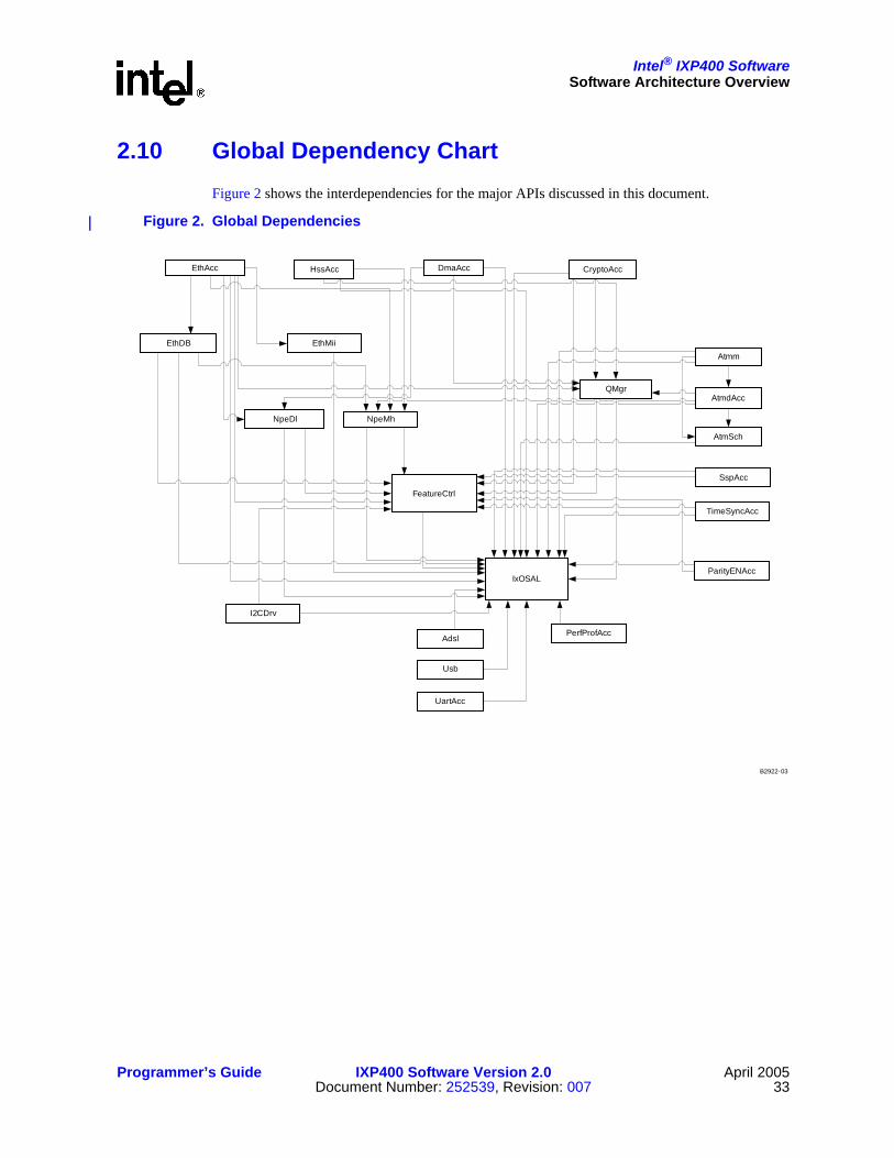
Intel® IXP400 SoftwareSoftware Architecture Overview
Programmer’s Guide IXP400 Software Version 2.0 April 2005Document Number: 252539, Revision: 007 33
2.10 Global Dependency ChartFigure 2 shows the interdependencies for the major APIs discussed in this document.
Figure 2. Global Dependencies
EthAcc
EthDB EthMii
IxOSAL
NpeDl NpeMh
FeatureCtrl
Usb
HssAcc DmaAcc
Adsl
CryptoAcc
UartAcc
Atmm
AtmdAcc
AtmSch
PerfProfAcc
B2922-03
SspAcc
TimeSyncAcc
I2CDrv
ParityENAcc
QMgr

This page is intentionally left blank.
Intel® IXP400 Software
April 2005 IXP400 Software Version 2.0 Programmer’s Guide34 Document Number: 252539, Revision: 007

Intel® IXP400 Software
Programmer’s Guide IXP400 Software Version 2.0 April 2005Document Number: 252539, Revision: 007 35
Buffer Management 3
This chapter describes the data buffer system used in Intel® IXP400 Software v2.0, and includes definitions of the IXP400 software internal memory buffers, cache management strategies, and other related information.
3.1 What’s New There are no changes or enhancements to this component in software release 2.0.
3.2 OverviewBuffer management is the general principle of how and where network data buffers are allocated and freed in the entire system. Network data buffers, whose formats are known to all involved components, need to flow between access-layer components.
As shown in Figure 3, the IXP400 software access-layer follows a simple buffer-management principle: All buffers used between access-layer component and clients above the access-layer component must be allocated and freed by the clients, that is, in this case, the operating system driver. The client passes a buffer to an access-layer component for various purposes (generally, Tx and Rx), and the access-layer component returns the buffer to the client when the requested job is completed. The access-layer component’s Operating System Abstraction Layer module provides the mapping of the OS buffer header fields to the IXP buffer format. Clients can also implement their own utilities to convert their buffers to the IXP_BUF format and vice-versa. Depending upon the service requested, the NPE modifies the IXP_BUF’s shared structure and hands the buffer back to the access-layer component. The Figure 3 shows different stages where the different fields in the IXP_BUF buffer gets updated at transmit and receive time.

Intel® IXP400 SoftwareBuffer Management
April 2005 IXP400 Software Version 2.0 Programmer’s Guide36 Document Number: 252539, Revision: 007
The access-layer component may call a client-registered callback function to return the buffer, or may put the buffer back on a free queue for the client to poll. The access-layer components utilize similar buffer management techniques when communicating with the NPEs.
The network data buffers and their formats (as well as management of the buffers), must be ‘familiar’ to all components so that the buffers can efficiently flow in the system. The IXP400 software uses two internal buffer formats for all network data:
• IXP_BUF
• raw buffer
These two formats are compatible with the IXP400 software’s access-layer components and NPEs.
IXP_BUF
The IXP_BUF is the Intel® IXP400 Software defined buffer format used by the access-layer components. As shown in Figure 4, the Operating System Abstraction Layer of Intel® IXP400 Software v2.0 provides the users with macros to read and write the IX_OSAL_MBUF fields of the IXP_BUF buffer. The Intel® IXP400 Software v2.0 users are expected to use the IX_MBUF_xxx macros provided with the API to access the IX_OSAL_MBUF fields.
Figure 3. Intel® IXP400 Software Buffer Flow
B-3824
Translation OSBUF<->IXP_BUF
RxFree Q
OS NPE
Tx Q
Access-layer Components
Rx Q
TxDone Q
AQM
Update IXP_BUF :ixp_ne
structure
Update IXP_BUF :ixp_ne
structure
OS buffer
Driver
OS buffer
Allocate IXP_BUF
buffer
Free IXP_BUF buffer
Transmit
Receive
ix_ne: shared structure gets updated
IX_MBUF: OS specific structure gets updated
ix_ctrl: Pool management fields gets updated

Intel® IXP400 SoftwareBuffer Management
Programmer’s Guide IXP400 Software Version 2.0 April 2005Document Number: 252539, Revision: 007 37
The usual fields to be updated between the user and the IXP_MBUF fields depends on the access-layer component, but most of the Intel® IXP400 Software API requires the use of following fields:
— IX_DATA
— IX_MLEN
— IX_PKTLEN
— IX_NEXT_BUFFER_IN_PKT_PTR (in case of chained buffers)
Raw Buffers
Raw buffer format is simply a contiguous section of memory represented in one of two ways. One way to pass raw buffers between two access-layer components is through an agreement to circularly access the same piece of raw buffer. One access-layer component circularly writes to the buffer while the other access-layer component circularly reads from the buffer. The buffer length and alignment are parts of the agreement. At run-time, another communication channel is needed to synchronize the read pointer and write pointers between the two components.
The other way to pass raw buffers between two components is through passing a pointer to the buffer between the components. If all buffers are the same size and that size is fixed, the length can be made known during configuration. Otherwise, another communication channel in run-time is needed to tell the length of the buffer. The raw buffer component is typically used for circuit-switched network data (that is, TDM-based). The access-layer component IxHssAcc channelized service uses raw buffers. Refer to Section 13.7.2 for additional information on raw buffers.
Note: Intel® IXP400 Software provides OSAL macros, which can be used to allocate memory for raw buffers as a substitute to allocating IXP_BUF from the pool.
Figure 4. IXP_BUF User Interface
B-3825
IXP_BUF macros
Users
IXP_BUF structure
IX_OSAL_MBUF fields

Intel® IXP400 SoftwareBuffer Management
April 2005 IXP400 Software Version 2.0 Programmer’s Guide38 Document Number: 252539, Revision: 007
3.3 IXP_BUF StructureAs shown in Figure 5, IXP_BUF is comprised of the following three main structures, and each structure is comprised of eight entries four bytes long.
1. The first structure consists of an eight word fields some of which are between the OS driver / API users and the access-layer components.
2. The second structure consists of internal fields used by the pool manager, which is provided by the OSAL component.
3. The third structure is the NPE Shared structure that is composed of common header fields and NPE service specific fields. Depending upon the access-component usage, some of the service specific fields such as VLAN tags may be available for the user through use of macros.
3.3.1 IXP_BUF Structure and Macros Users are expected to use the following IXP_BUF macros provided to access IXP_BUF subfields. The Figure 6 shows macros defined by the OSAL layer component to be used to access the IXP_BUF fields.
Figure 5. IXP_BUF Structure
B-3826
IX_MBUF: OS Dependent Buffer formatStructure 1
Structure 3
Structure 2 ix_ctrl: Pool Management Fields
ix_ne: NPE Shared structure
IXP_BUF structure

Intel® IXP400 SoftwareBuffer Management
Programmer’s Guide IXP400 Software Version 2.0 April 2005Document Number: 252539, Revision: 007 39
Figure 6. OSAL IXP_BUF structure and macros
Depending upon the usage model, different software components use the structures to update the internal fields of the IXP_BUF structure. Figure 7 shows a typical interface for the API users or operating system drivers to the IXP_BUF fields. Depending upon the access-layer components in use the API user may or may not use the service-specific macros to read the NPE-shared structure of the IXP_BUF fields. Reading of the MAC address or a VLAN tag for a quick classification is an example of NPE-shared structure use.
B-3827
OSAL macros for IXP400 IXP_BUFIXP_BUF fields
Cac
he L
ine
ix_next
ix_nextPacket
ix_data
ix_type ix_flags ix_reserved
ix_rsvd
ix_priv
ix_len
ix_PktLen
IX_OSAL_MBUF_NEXT_PKT_IN_CHAIN_PTR
IX_OSAL_MBUF_MDATA
IX_OSAL_MBUF_MLEN
IX_OSAL_MBUF_MTYPE/MFLAGS
IX_OSAL_MBUF_NEXT_BUFFER_IN_PKT_PTR
IX_OSAL_MBUF_PKT_LEN
IX_OSAL_MBUF_PRIV
Cac
he L
ine
IX_OSAL_MBUF_OSBUF_PTR
IX_OSAL_MBUF_NET_POOL
IX_OSAL_MBUF_ALLOCATED_MBUF_DATA
IX_OSAL_MBUF_SIGNATURE
IX_OSAL_MBUF_ALLOCATED_MBUF_LEN
Cac
he L
ine
Reserved (Shared with NPE)
Reserved (Shared with NPE)
Reserved (Shared with NPE)
Reserved (Shared with NPE)
Reserved (Shared with NPE)
Reserved (Shared with NPE)
Reserved (Shared with NPE)
Reserved (Shared with NPE)
ReservedReserved
User visible
Shared with NPE
IXP400 SW v1.4
Reserved for NPE-Service specific usage
Used by Intel IXP400 SW v1.5 for pool management / Reserved
Fields used by Intel IXP400 version 1.4
OS dependent fields, may be modified by access-layer componentUser visible
OS dependent fields, not modified by access-layer component
v1.5 Pool management
ix_allocated_data
ix_pool
ix_osbuf_ptr
ix_chain
ix_allocated_len
ix_signature

Intel® IXP400 SoftwareBuffer Management
April 2005 IXP400 Software Version 2.0 Programmer’s Guide40 Document Number: 252539, Revision: 007
Figure 7. API User Interface to IXP_BUF
The Figure 8 shows a typical interface between the Intel® IXP400 Software access-layer components and the IXP_BUF fields. The access-layer components adapt to the endianness as defined by the Intel XScale core. The access-layer components can perform reads and write to the IX_MBUF fields as well as the NPE-shared structure. The service-specific fields to be updated in the NPE-shared structure may vary depending upon access-component needs.
Figure 8. Access-Layer Component Interface to IXP_BUF
B-3828
IX_MBUFData, len …
same fields across all APIs)
Reserved for pool management and extra fields
ix_ne: NPE shared structure
(service specific)
IXP_BUF
IX_OSAL_MBUF_XXX macros (data, length …)
API User (e.g. driver)
IX_ETHACC_NE_XXX service-specific macros
(e.g. flags)
API USER
B-3829
IX_MBUFData, len …
same fields across all APIs)
Reserved for pool management and extra fields
ix_ne: NPE Shared structure
(service specific)
IXP_BUF
IX_OSAL_MBUF_XXX macros
Access-layer components
IX_Component_NE_XXX service-specific macros
ACCESS-LAYER components

Intel® IXP400 SoftwareBuffer Management
Programmer’s Guide IXP400 Software Version 2.0 April 2005Document Number: 252539, Revision: 007 41
Figure 9 below shows the interface between the OSAL pool management module and the pool management fields used for pool maintenance. The pool management field also stores the os_buf_ptr field, which is used by the access-layer to retrieve the original pointer to the OS buffer and is set at the time of pool allocation.
Figure 9. Pool Management Fields
IX_MBUF: OS-Dependent Buffer Format
As shown in Figure 10, the IX_MBUF information follows a format originally defined in Berkeley Software Distribution (BSD) TCP/IP code distribution to preserve the backward compatibility with previous Intel® IXP400 Software releases. The OSAL layer provides translation functions to map the OS-dependent buffer format to the IX_MBUF format for Linux* and VxWorks* operating systems. This simplifies the buffer management without sacrificing functionality and flexibility.
Figure 10. IXP_BUF: IX_MBUF Structure
IX_MBUF Data, len …
(standard along CSR APIs)
Reserved for pool management and extra fields
ix_ne: NPE Shared structure
(service specific)
IXP_BUF
IX_OSAL_MBUF_POOL
Pool manager field macros and field names
ix_next
ix_nextpacket
ix_data
ix_len
ix_rsvd
ix_PktLen
ix_reservedix_type ix_flags
Reserved
IX_MBUF: 1st Structure of IXP_BUF(IX_MBUF fields)

Intel® IXP400 SoftwareBuffer Management
April 2005 IXP400 Software Version 2.0 Programmer’s Guide42 Document Number: 252539, Revision: 007
Linux utilizes memory structures called skbuffs. The user allocates IXP_BUF and sets the data payload pointer to the skbuff payload pointer. An os_buf_ptr field inside the ixp_ctrl structure (defined below) of the IXP_BUF is used to save the actual skbuff pointer. In this manner, the OS buffers are not freed directly by the IXP400 software.
The IXP400 software IXP_BUF to skbuff mapping is a ‘zero-copy’ implementation. There is no copy/performance penalty in using Linux skbuffs. Other proprietary buffer schemes could also be implemented with the IXP400 software using the mbuf-to-skbuff implementation as an example.
ix_ctrl: Intel® IXP400 Software Internal Pool Management Fields
As shown in Figure 11, the ix_ctrl fields are set and used by the IXP_BUF pool manager provided by the OSAL component. Some of the fields can be used for specific purposes for different operating systems For example, signature verification fields is used in Linux when NDEBUG is enabled. The reserved field may be used in VxWorks to support IPv6 format.
Figure 11. IXP_BUF: ix_ctrl Structure
ix_ne: IXP400 NPE Shared Structure
As shown in Figure 12, this structure is provided by the Intel XScale core to the NPE. Depending upon the access-layer component usage, some of these fields may be visible to the user through use of macros and also may be altered by the NPE. The lower five words of this structure are defined according to the needs of NPE microcode; therefore, different NPE images may have different structure for this part. The upper three words follows the same structure across all the NPE images.
Note: Users should not make any assumptions to usage of the service-specific fields in this NPE-shared structure. The fields are for internal NPE usage only.
Reserved
ix_osbuf_ptr
ix_chain
ix_allocated_data
ix_pool
ix_allocated_len
ix_signature
Reserved
ix_ctrl: 2nd Structure of IX_BUF(Internal fields)

Intel® IXP400 SoftwareBuffer Management
Programmer’s Guide IXP400 Software Version 2.0 April 2005Document Number: 252539, Revision: 007 43
Figure 12. IXP_BUF: NPE Shared Structure
3.4 Mapping of IX_MBUF to Shared StructureThe Figure 13 below shows an example case on how the IX_MBUF headers are internally mapped to the NPE shared structure as in the case of the Ethernet and Crypto access-layer components only. The IX_MBUF standard buffer format is used throughout the access-layer code. In order to minimize overhead in reading the whole buffer control structure from the memory to the NPE while performing NPE-specific services, the pointer to the NPE shared structure is passed to the NPE for processing the data instead of the buffer descriptor pointer itself. Therefore, for the access-layer components, only the required information (such as next buffer pointer, buffer data pointer, buffer length and packet length) from the buffer control structure is copied into NPE shared structure. Depending upon the endianness, the IXP400 software internally swaps the buffers of packetised data and the headers between the upper software layers and the NPEs for the Ethernet and the Crypto access-layer components. It is important to note that NPE shared buffer format used by the IXP400 software is hard-coded in the NPE microcode. It is not possible to change this shared buffer format.
ixp_next
ixp_data
N P E S erv ice S pec ific F ie ld
ixp_len ixp_pk t_ len
N P E S erv ice S pec ific F ie ld
N P E S erv ice S pec ific F ie ld
N P E S erv ice S pec ific F ie ld
N P E S erv ice S pec ific F ie ld
ix_n e: 3 rd S tru c tu re o f IX _B U F(N P E S h ared s tru c tu re )

Intel® IXP400 SoftwareBuffer Management
April 2005 IXP400 Software Version 2.0 Programmer’s Guide44 Document Number: 252539, Revision: 007
Figure 13. Internal Mapping of IX_MBUF to the Shared NPE Structure
3.5 IX_MBUF StructureTable 1 and Table 2 present IX_MBUF structure format and details.
ix_next
ix_nextpkt
ix_data
ix_len
ix_rsvd
ix_len
ix_reservedix_type ix_flags
ixp_next
ixp_data
NPE Service Specific Field
ixp_len ixp_pkt_len
1st Cacheline of
IXP_BUF
NPE Service Specific Field
NPE Service Specific Field
NPE Service Specific Field
NPE Service Specific Field
M apping from IX_M BUF to NPE SharedStructure
2nd Cacheline of
IXP_BUF
Table 1. Internal IX_MBUF Field Format (Sheet 1 of 2)
0 1 2 3
0 ix_next (IX_OSAL_MBUF_NEXT_BUFFER_IN_PKT_PTR)
4 ix_nextPacket (IX_OSAL_MBUF_NEXT_PKT_IN_CHAIN_PTR)
8 ix_data (IX_OSAL_MBUF_MDATA)
12 ix_len (IX_OSAL_MBUF_MLEN)
16 ix_type ix_flags ix_reserved

Intel® IXP400 SoftwareBuffer Management
Programmer’s Guide IXP400 Software Version 2.0 April 2005Document Number: 252539, Revision: 007 45
A set of macros are provided for the IXP400 software to access each of the fields in the buffer structure. Each macro takes a single parameter – a pointer to the buffer itself. Each macro returns the value stored in the field. More detail on the field, their usage, and the macros are detailed in the table below.
Note: The data pointer IX_OSAL_MBUF_MDATA could be aligned on a 16 bit boundary to help align an IP header on a 32 bit boundary.
20 ix_rsvd
24 ix_pktlen
28 ix_priv(Reserved)
Table 1. Internal IX_MBUF Field Format (Sheet 2 of 2)
0 1 2 3
Table 2. IX_MBUF Field Details (Sheet 1 of 2)
Field / MACRO Purpose Used by Access-Layer?
IX_OSAL_MBUF_NEXT_BUFFER_IN_PKT_PTRParameter type: IX_MBUF *Return type: IX_MBUF *Description: Returns a 32-bit pointer to the next buffer in the packet
32-bit pointer to the next buffer in a chain (linked list) of buffers. NULL entry marks end of chain.
Yes, where buffer chaining is supported.
IX_OSAL_MBUF_NEXT_PKT_IN_CHAIN_PTRParameter type: IX_MBUF *Return type: IX_MBUF *Description: Returns a 32-bit pointer to the first buffer in the next packet in the packet chain
32-bit pointer to the next packet in a chain (linked list) of packets. NULL entry marks end of chain. Each packet in the chain may consist of a chain of buffers.
No. Packet chaining is not supported by IXP400 Software.
IX_OSAL_MBUF_MDATAParameter type: IX_MBUF *Return type: char *Description: Returns a pointer to the first byte of the buffer data
32-bit pointer to the data section of a buffer. The data section typically contains the payload of a network buffer.
Yes. But does not get modified by the access-layer
IX_OSAL_MBUF_MLENParameter type: IX_MBUF *Return type: intDescription: Returns the number of octets of valid data in the data section of the buffer
Lengths (octets) of valid data in the data section of the buffer. Yes.
IX_OSAL_MBUF_TYPEParameter type: IX_MBUF *Return type: unsigned charDescription: Returns the type field of the buffer
Buffer type Yes, by some components.

Intel® IXP400 SoftwareBuffer Management
April 2005 IXP400 Software Version 2.0 Programmer’s Guide46 Document Number: 252539, Revision: 007
3.6 Mapping to OS Native Buffer TypesOSAL provides buffer-translation macros for users to translate OS-specific buffer formats to OSAL IXP buffer format and vice versa. The mapping of OS buffer fields to the IXP400 software buffer format is usually done in the OS specific driver component. However, for ease of users the OSAL component provides generic macros for VxWorks, and Linux operating system that does the translation. Depending upon the build, the OSAL component will translate the macros to its OS-specific implementation. The general syntax for using these macros is as follows:
• IX_OSAL_CONVERT_OSBUF_TO_IXPBUF(osBufPtr,ixpBufPtr)
• IX_OSAL_CONVERT_IXPBUF_TO_OS_BUF(ixpBufPtr,osBufPtr)
These macros are intended to replace Linux skbuf and VxWorks mbuf conversions. Users can also define their own conversion utilities in their package to translate their buffers to IXP buffers (IX_OSAL_MBUF).
3.6.1 VxWorks* M_BLK BufferThe first structure IX_MBUF of the IXP_BUF buffer format is compatible with VxWorks M_BLK structure. It is also intended to provide a backward compatibility to previous Intel® IXP400 Software release. For this reason, when compiled for VxWorks, the IX_MBUF buffer format is compatible directly as an M_BLK buffer. The Intel® IXP400 Software does not make use of all the fields defined by the M_BLK buffer. The macros listed in Table 3 are used by the IXP400 software to access the correct fields within the M_BLK structure.
The M_BLK structure is defined in the global VxWorks header file “netBufLib.h”.
IX_OSAL_MBUF_FLAGSParameter type: IX_MBUF *Return type: unsigned charDescription: Returns the flags field of the buffer
Buffer flags. Yes, by some components.
Reserved Reserved field, used to preserve 32-bit word alignment. No.
IX_OSAL_MBUF_NET_POOLParameter type: IX_MBUF *Return type: unsigned intDescription: Returns a 32-bit pointer to the parent pool of the buffer
32-bit pointer to the parent pool of the buffer Yes, by some components.
IX_OSAL_MBUF_PKT_LENParameter type: IX_MBUF *Return type: unsigned intDescription: Returns the length of the packet (typically stored in the first buffer of the packet only)
Total length (octets) of the data sections of all buffers in a chain of buffers (packet). Typically set only in the first buffer in the chain (packet).
Yes, where buffer chaining is supported.
Reserved Used by VxWorks* No.
Table 2. IX_MBUF Field Details (Sheet 2 of 2)
Field / MACRO Purpose Used by Access-Layer?

Intel® IXP400 SoftwareBuffer Management
Programmer’s Guide IXP400 Software Version 2.0 April 2005Document Number: 252539, Revision: 007 47
Note that the M_BLK structure contains many fields that are not used by the IXP400 software. These fields are simply ignored and are not modified by the IXP400 software.
M_BLK buffers support two levels of buffer chaining:
• buffer chaining — Each buffer can be chained together to form a packet. This is achieved using the IX_MBUF_NEXT_BUFFER_IN_PKT_PTR equivalent field in the M_BLK. This is supported and required by the IXP400 software.
• packet chaining — Each packet can consist of a chain of one or more buffers. Packets can also be chained together (to form a chain of chains). This is not used by the IXP400 software. The IX_MBUF_NEXT_PKT_IN_CHAIN_PTR equivalent field of the M_BLK buffer structure is used for this purpose. Most IXP400 software components will ignore this field.
Note: The VxWorks netMbuf pool library functions will not be supported to allocate and free the IXP_BUF buffers.
Table 3 shows the field mapping between the IX_MBUF and the M_BLK buffer structures through OSAL macros.
3.6.2 Linux* skbuff BufferThe buffer format native to the Linux OS is the “skbuff” buffer structure, which is significantly different from the IX_MBUF buffer format used by the IXP400 software.
The Linux skbuf structure is attached to the os_buf_ptr field during transmit or receive and is detached during TxDone. The user must allocate an IXP_BUF header, make a call to a translational function and pass the IXP_BUF buffer to the IXP400 software release. The translation functions enter all the required fields from the OS buffers to respective fields in the first structure, that is, the IX_MBUF structure within the IXP_BUF structure. The translation of fields from the IX_MBUF structure into the NPE shared structure is accomplished by the OSAL component on Transmit and Receive Replenish. On TxDone the user may recycle the IXP_BUF back to the IXP_BUF_POOL or to an internal data structure.
The OSAL layer provides buffer translation macros for users to translate OS-specific buffer formats to IXP_BUF buffer format and vice versa.
Table 3. IX_MBUF to M_BLK Mapping
IX_MBUF M_BLK
IX_OSAL_MBUF_NEXT_BUFFER_IN_PKT_PTR mBlkHdr.mNext
IX_OSAL_MBUF_NEXT_PKT_IN_CHAIN_PTR mBlkHdr.mNextPkt
IX_OSAL_MBUF_MDATA mBlkHdr.mData
IX_OSAL_MBUF_MLEN mBlkHdr.mLen
IX_OSAL_MBUF_TYPE mBlkHdr.mType
IX_OSAL_MBUF_FLAGS mBlkHdr.mFlags
IX_OSAL_reserved mBlkHdr.reserved
IX_OSAL_MBUF_NET_POOL mBlkPktHdr.rcvif
IX_OSAL_MBUF_PKT_LEN mBlkPktHdr.len
priv pClBlk

Intel® IXP400 SoftwareBuffer Management
April 2005 IXP400 Software Version 2.0 Programmer’s Guide48 Document Number: 252539, Revision: 007
It works on the following principles:
• Each IXP_BUF is mapped to an skbuff (1:1 mapping)
• The os_buf_ptr field of the ix_ctrl structure is used to store a pointer to the corresponding skbuff.
• The ix_data pointer field of the IX_MBUF structure within the IXP_BUF structure will be set to point to the data field of the corresponding skbuff through use of the IX_OSAL_MBUF_MDATA macro.
• The ix_len and ix_pkt_len fields of the IX_MBUF structure within the IXP_BUF structure will be set to the length of the skbuff data section (the len field in the skbuff structure) through use of the IX_OSAL_MBUF_PKT_LEN and IX_OSAL_MBUF_MLEN macros.
The prototype for this function is shown in Table 4.
The suggested usage model of this function is:
• Allocate a pool of IXP_BUF buffer headers. Do not allocate data sections for these buffers.
• When passing a buffer from higher-level software (for example, OS network stack) to the IXP400 software, attach the skbuff to an IXP_BUF using the translation function.
• When receiving an IXP_BUF passed from the IXP400 software to higher-level software, use the translation function to retrieve a pointer to the skbuff that was attached to the IXP_BUF, and use that skbuff with the OS network stack to process the data.
The Intel® IXP400 Software Linux Ethernet Device driver (“ixp425_eth.c”), which is included in the IXP400 software distribution in form of a patch, contains an example of this suggested usage model.
Table 4. Buffer Translation Functions
• IX_OSAL_CONVERT_OSBUF_TO_IXPBUF(osBufPtr,ixpBufPtr)
The following fields of IX_MBUF within the IXP_BUF structure will get updated:
— ix_len
— ix_pktlen
— ix_data
— ix_ctrl.os_buf_ptr
• IX_OSAL_CONVERT_IXPBUF_TO_OS_BUF(ixpBufPtr)
The following fields will get updated in the skbuffer
— (skb)osBufPtr = ix_ctrl.os_buf_ptr
— skb->data = IX_OSAL_MBUF_MDATA(ixMbufPtr)
— skb->len = IX_OSAL_MBUF_MLEN(ixMbufPtr)
— skb->len = IX_OSAL_MBUF_PKT_LEN(ixMbufPtr)

Intel® IXP400 SoftwareBuffer Management
Programmer’s Guide IXP400 Software Version 2.0 April 2005Document Number: 252539, Revision: 007 49
3.7 Caching StrategyThe general caching strategy in the IXP400 software architecture is that the software (include Intel XScale core-based code and NPE microcode) only concerns itself with the parts of a buffer which it modifies. For all other parts of the buffer, the user (higher-level software) is entirely responsible.
IXP_BUF buffers typically contain a header section and a data section. The header section contains fields that can be used and modified by the IXP400 software and the NPEs. Examples of such fields are:
• pointer to the data section of the IXP_BUF
• length of the data section of the mbuf
• pointer to the next mbuf in a chain of mbufs
• buffer type field
• buffer flags field
As a general rule, IXP400 software concerns itself only with IXP_BUF headers, and assumes that the user (that is, higher-level software) will handle the data section of buffer.
The use of cached memory for IXP_BUF buffer is strongly encouraged, as it will result in a performance gain as the buffer data is accessed many times up through the higher layers of the operating system’s network stack. However, use of cached memory has some implications that need to be considered when used for buffers passed through the IXP400 software Access-Layer.
The code that executes on Intel XScale core accesses the buffer memory via the cache in the Intel XScale core MMU. However, the NPEs bypass the cache and access this external SDRAM memory directly. This has different implications for buffers transmitted from Intel XScale core to NPE (Tx path), and for buffers received from NPE to Intel XScale core (Rx path).
3.7.1 Tx PathIf a buffer in cached memory has been altered by Intel XScale core code, the change will exist in the cached copy of the IXP_BUF, but may not be written to memory yet. In order to ensure that the memory is up-to-date, the portion of cache containing the altered data must be flushed.
The cache flushing strategy uses the following general guidelines:
• The “user” is responsible for flushing the data section of the IXP_BUF. Only those portions of the data section which have been altered by the Intel XScale core code need to be flushed. This must be done before submitting an IXP_BUF to the IXP400 software for transmission via the component APIs (for example, ixEthAccPortTxFrameSubmit().
• The IXP400 software is responsible for writing and flushing the ix_ne shared section of the buffer header. This must be done before submitting an IXP_BUF to the NPE. Communication to the NPEs is generally performed by access-layer components by sending IXP_BUF headers through the IxQMgr queues.
Since flushing portions of the cache is an expensive operation in terms of CPU cycles, it is not advisable to simply flush both the header and data sections of each IXP_BUF. To minimize the performance impact of cache-flushing, the IXP400 software only flushes that which it modifies (the IXP_BUF header) and leaves the flushing of the data section as the responsibility of the user. The user can minimize the performance impact by flushing only what it needs to.

Intel® IXP400 SoftwareBuffer Management
April 2005 IXP400 Software Version 2.0 Programmer’s Guide50 Document Number: 252539, Revision: 007
Tx Cache Flushing Example
In the case of an Ethernet bridging system, only the user can determine that it is not necessary to flush any part of the packet payload. In a routing environment, the stack can determine that only the beginning of the mbuf may need to be flushed (for example, if the TTL field of the IP header is changed). Additionally, with the VxWorks OS, mbufs can be from cached memory or uncached memory. Only the user knows which buffers need to be flushed or invalidated and which buffers do not.
When the NPE has transmitted the data in a buffer, it will return the buffer back to the Intel XScale core. In most cases, the cache copy is still valid because the NPE will not modify the contents of the buffer on transmission. Therefore, as a general rule, the IXP400 software does not invalidate the cached copy of IXP_BUF used for transmission after they are returned by the NPE.
3.7.2 Rx PathIf a buffer has been altered by an NPE, the change will exist in memory but the copy of the buffer in Intel XScale core cache may not be up-to-date. We need to ensure that the cached copy is up-to-date by invalidating the portion of cache that contains the copy of the altered buffer data.
The strategy for dealing with data received by the NPEs uses the following general guidelines:
• The “user” is responsible for invalidating the data section of the IXP_BUF. Again, only the user knows which portions of the data section it needs to access. In some instances, the user may be required to submit free IXP_BUFs that are to be used to hold received data (for example, ixEthAccPortRxFreeReplenish()). It is strongly recommended that the cache location holding the data portion of the free IXP_BUFs be invalidated before submitting them via the API.
• The IXP400 software is responsible for writing and flushing the ix_ne shared section of the buffer header. The IXP400 software may modify the header of the IXP_BUF before passing it to the NPE, hence the need to flush and then invalidate the header section of the IXP_BUF. This should be done before submitting an IXP_BUF to the NPE for reception (via IxQMgr queues).
Note: In some cases, the Access-Layer will flush the header section of the IXP_BUF before submitting the IXP_BUF to the NPE, and will invalidate the header section after receiving it back from the NPE with data. This approach is also acceptable; however, the approach listed above is considered more efficient and more robust.
As in the flushing operations listed in the previous section, invalidating portions of the cache is an expensive operation in terms of CPU cycles. To minimize the performance impact of cache-invalidating, the IXP400 software only invalidates that which it modifies (the IXP_BUF header) and leaves the invalidating of the data section as the responsibility of the user. The user can minimize the performance impact by invalidating only what is necessary. When recycling IXP_BUFs, only the user knows what was the previous use of the IXP_BUF and the parts of payload that may need to be invalidated.
3.7.3 Caching Strategy SummaryBefore the NPE reads the memory, ensure that the memory is up-to-date by flushing cached copies of any parts of the buffer memory modified by the Intel XScale core.

Intel® IXP400 SoftwareBuffer Management
Programmer’s Guide IXP400 Software Version 2.0 April 2005Document Number: 252539, Revision: 007 51
After the NPE modifies the memory, ensure that the Intel XScale core MMU cache is up-to-date by invalidating cached copies of any parts of the buffer memory that the Intel XScale core will need to read. It is more robust to invalidate before the NPE gets a chance to write to the SDRAM.
OS-independent macros are provided for both flushing (IX_ACC_DATA_CACHE_FLUSH) and invalidating (IX_ACC_DATA_CACHE_INVALIDATE). For more information, refer to the header file ixp_osal/include/IxOsal.h).

This page is intentionally left blank.
Intel® IXP400 Software
April 2005 IXP400 Software Version 2.0 Programmer’s Guide52 Document Number: 252539, Revision: 007

Intel® IXP400 Software
Programmer’s Guide IXP400 Software Version 2.0 April 2005Document Number: 252539, Revision: 007 53
Access-Layer Components:ATM Driver Access (IxAtmdAcc) API 4
This chapter describes the Intel® IXP400 Software v2.0’s “ATM Driver-Access” access-layer component.
4.1 What’s NewThere are no changes or enhancements to this component in software release 2.0.
4.2 OverviewThe ATM access-driver component is the IxAtmdAcc software component and provides a unified interface to AAL transmit and receive hardware. The software release 2.0 supports AAL 5, AAL 0, and OAM. This component provides an abstraction to the IXP4XX product line and IXC1100 control plane processors’ ATM cell-processing hardware. It is designed to support ATM transmit and receive services for multiple ports and VCs.
This chapter describes the configuration, control, and transmit/receive flow of ATM PDU data through the IxAtmdAcc component.
The general principle of improving performance by avoiding unnecessary copying of data is adhered to in this component. The BSD-based buffering scheme is used.
Since AAL 0 is conceptually a raw cell service, the concept of an AAL-0 PDU can be somewhat misleading. In the context of software release 2.0, an AAL-0 PDU is defined as containing an integral number of 48-byte (cell payload only) or 52-byte (cell payload and cell header without HEC field) cells.
4.3 IxAtmdAcc Component FeaturesThe services offered by the ixAtmdAcc component are:
• Supports the configuration and activation of up to 12 ports on the UTOPIA Level-2 interface.
• Supports AAL-5 CPCS PDUs transmission service, which accepts fully formed PDUs for transmission on a particular port and VC. AAL-5 CRC calculation is performed by hardware. (PDUs may consist of single or chained IXP_BUFs.)
• Supports AAL-0-48 PDU transmission service, which accepts PDUs containing an integral number of 48-byte cells for transmission on a particular port and VC. (PDUs may consist of single or chained IXP_BUFs.)

Intel® IXP400 SoftwareAccess-Layer Components: ATM Driver Access (IxAtmdAcc) API
April 2005 IXP400 Software Version 2.0 Programmer’s Guide54 Document Number: 252539, Revision: 007
• Support AAL-0-52 PDU transmission service, which accepts PDUs containing an integral number of 52-byte cells for transmission on a particular port and VC. (PDUs may consist of single or chained IXP_BUFs.)
• Supports OAM PDU transmission service, which accepts PDUs containing an integral number of 52-byte OAM cells for transmission on a particular port independent of the VC. (PDUs may consist of single or chained IXP_BUFs.)
• Supports ATM traffic shaping
— Scheduler registration: Allows registration of ATM traffic-shaping entities on a per-ATM-port basis. A registered scheduler must be capable of accepting per-VC-cell demand notifications from AtmdAcc.
— Transmission control: Allows ATM traffic-shaping entities to determine when cells are sent and the number of cells sent from each VC at a time.
• Supports setting or viewing the CLP for AAL-5 CPCS SARed PDUs.
• Supports setting the transmit CLP CUP in all cells of an AAL-0-48 PDU.
• Supports the client setting the transmit GFC, PTI, or CLP in any cell of an AAL-0-52/OAM PDU.IxAtmdAcc does not process cell headers for AAL-0-52/OAM, thus GFC, PTI, and CLP must be set in the cell headers in the PDU by the client. (The HEC is not included.)
• Supports delivery of fully formed AAL-5 CPCS PDUs received on a particular port and VC with error detection for CRC errors, priority queuing, and corrupt-packet delivery.(PDUs may consist of single or chained IXP_BUFs.)
• Supports delivery of AAL-0 PDU containing 48-byte cells (with good HEC) — received on a particular port and VC.
• Supports delivery of AAL-0 PDU containing 52-byte cells — received on a particular port and VC.
• Supports delivery of an OAM PDU containing a single, 52-byte OAM cell (with good HEC, and good CRC-10) — received on any port and any VC.
• Allows the client to determine the port on which the PDU was received, for all client service types.
• Supports viewing the receive CLP of an AAL-0-48 PDU (logical or of the CLP value in each cell contained in the PDU).
• Allows the client to view the GFC, PTI, or CLP of any cell in a received AAL-0-52/OAM PDU.The component does not process cell headers for AAL-0-52/OAM. CLP may be read from the header cells in the PDU by the client.
• Supports up to 32 VCC channels for transmit services and up to 32 channels for AAL-0/AAL-5 receive services. One client per channel is supported.
• Supports one dedicated OAM transmit channel (OAM-VC) per port. This channel supports transmission of OAM cells on any VC.
• Supports one dedicated OAM receive channel (OAM-VC) for all ports. This channel supports reception of OAM cells from any port on any VC.
• Provides an interface to retrieve statistics unavailable at the client layer.

Intel® IXP400 SoftwareAccess-Layer Components: ATM Driver Access (IxAtmdAcc) API
Programmer’s Guide IXP400 Software Version 2.0 April 2005Document Number: 252539, Revision: 007 55
These statistics include the number of cells received, the number of cells receive with an incorrect cell size, the number of cells containing parity errors, the number of cells containing HEC errors, and the number of idle cells received.
• Provides an interface to use either a threshold mechanism — which allows the client actions to be driven by events — or a polling mechanism — through which the client decides where and when to invoke the functions of the interface.
• Supports fast-path-exception packet processing.
• Supports use in a complete user environment, a complete-interrupt environment, or a mixture of both.This is done by providing the control over the Rx and TxDone dispatch functions and transmit and replenish functions. The user may trigger them from interrupts, or poll them, or both, assuming an exclusion mechanism is provided as needed.
The ixAtmdAcc component communicates with the NPEs’ ATM-over-UTOPIA component through entries placed on Queue Manager queues, IXP_BUFs, and associated descriptors — located in external memory and through the message bus interface.
4.4 Configuration ServicesIxAtmdAcc supports three configuration services:
• UTOPIA port configuration
• ATM traffic shaping
• VC configuration
4.4.1 UTOPIA Port-Configuration ServiceThe UTOPIA interface is the IXP4XX product line and IXC1100 control plane processors’ interface by which ATM cells are sent to and received from external PHYs. In order to configure the UTOPIA interface, IxAtmdAcc provides an interface that allows a configuration structure to be sent to and/or retrieved from the UTOPIA interface.
IxAtmdAcc provides the interface to configure the hardware and enable/disable traffic on a per-port basis.
4.4.2 ATM Traffic-Shaping ServicesAn ATM scheduling entity provides a mechanism where VC traffic on a port is shaped in accordance with its traffic parameters. IxAtmdAcc does not itself provide such a traffic-shaping service, but can be used in conjunction with external scheduling services.
The scheduler registration interface allows registration of ATM traffic-shaping entities on a per-port basis. These entities, or proxies thereof, are expected to support the following callbacks on their API:
• Function to exchange VC identifiers.A VC identifier identifies a port, VPI, and VCI and is usually specific to layer interface. IxAtmdAcc has an identifier known as a connId and the scheduling entity is expected to have

Intel® IXP400 SoftwareAccess-Layer Components: ATM Driver Access (IxAtmdAcc) API
April 2005 IXP400 Software Version 2.0 Programmer’s Guide56 Document Number: 252539, Revision: 007
its own identifier known as a scheduler VcId. This callback also serves to allow the scheduling entity to acknowledge the presence of VC.
• Function to submit a cell count to the scheduling entity on a per-VC basis.This function is used every time the user submits a new PDU for transmission.
• Function to clear the cell count related to a particular VC.This function is used during a disconnect to stop the scheduling services for a VC.
No locking or mutual exclusion is provided by the IxAtmdAcc component over these registered functions.
The transmission-control API expects to be called with an updated transmit schedule table on a regular basis for each port. This table contains the overall number of cells, the number of idle cells to transmit, and — for each VC — the number of cells to transmit to the designated ATM port.
The ATM Scheduler can be different for each logical port and the choice of the ATM scheduler is a client decision. ATM scheduler registrations should be done before enabling traffic on the corresponding port. Once registered, a scheduler cannot be unregistered. If no ATM scheduler is registered for one port, transmission for this port is done immediately.
4.4.3 VC-Configuration ServicesIxAtmdAcc provides an interface for registering VCs in both Tx and Rx directions. The ATM VC is identified by a logical PHY port, an ATM VPI, and an ATM VCI. The total number of ATM AAL-5 or AAL-0 VCs supported — on all ports and in both directions — is 32. IxAtmdAcc supports up to 32 Rx channels, and up to 32 Tx channels on all ports. For AAL-5 and AAL-0, the number of logical clients supported per-VC is one.
In addition to the 32 VCs mentioned above, one dedicated OAM transmit VC per port and one dedicated OAM receive VC are supported. These dedicated OAM VCs behave like an “OAM interface” for the OAM client, and are used to carry OAM cells for any VPI/VCI (even if that VPI/VCI is one of the 32 connected for AAL services).
In the Tx direction, the client has to register the ATM traffic characteristics to the ATM scheduler before invoking the IxAtmDAcc “connect” function. The TxVcConnect function does the following actions:
• Checks if the PHY port is enabled.
• Checks for ATM VC already in use in an other TX connection.
• Checks if the service type is OAM and, if so, checks that the VC is the dedicated OAM-VC for that port.
• Checks the registration of this VC to the registered ATM scheduler.
• Binds the VC with the scheduler associated with this port.
• Registers the callback by which transmitted buffers get recycled.
• Registers the notification callback by which the hardware will ask for more data to transmit.
• Allocates a connection ID and return it to the client.
In the Rx directions, the RxVcConnect steps involve the following actions:
• Check if the PHY port is enabled.

Intel® IXP400 SoftwareAccess-Layer Components: ATM Driver Access (IxAtmdAcc) API
Programmer’s Guide IXP400 Software Version 2.0 April 2005Document Number: 252539, Revision: 007 57
• Check for ATM VC already in use in an other Rx connection.
• Check if the service type is OAM and, if so, check that the VC is the dedicated OAM-VC.
• Register the callback by which received buffers get pushed into the client’s protocol stack.
• Register the notification callback by which the hardware will ask for more available buffers.
• Allocate a connection ID and return it to the client.
When connecting, a connection ID is allocated and must be used to identify the VC, in all calls to the API. The connection IDs for Receive and Transmit, on the same ATM VC, are different.
The client has the choice of using a threshold mechanism provided by IxAtmdAcc or polling the different resources. When using the threshold mechanism, the client needs to register a callback function and supply a threshold level. As a general rule, when configuring threshold values for different services, the lower the threshold value is, the higher the interrupt rate will be.
4.5 Transmission ServicesThe IxAtmdAcc transmit service currently supports AAL 5, AAL 0-48, AAL 0-52, and OAM only and operates in scheduled mode.
In scheduled mode, buffers are accepted and internally queued in IxAtmdAcc until they are scheduled for transmission by a scheduling entity. The scheduling entity determines the number cells to be transmitted from a buffer at a time, this allows cells from different VCs to be interleaved on the wire.
AtmdAcc accepts outbound ATM payload data for a particular VC from its client in the form of chained IXP_BUFs. For AAL 5, an IXP_BUF chain represents an AAL-5 PDU which can contain 0-65,535 payload octets. A PDU is, however, a multiple of 48 octets, when padding and the AAL-5 trailer are included. For AAL 0-48/AAL 0-52/OAM, an IXP_BUF chain represents a PDU where the maximum length is limited to 256 chained IXP_BUFs and/or 65,535 octets.
The submission rate of buffers for transmission should be based on the traffic contract for the particular VC and is not known to IxAtmdAcc. However, there will be a maximum number of buffers that IxAtmdAcc can hold at a time and a maximum number of buffers that the underlying hardware can hold — before and during transmission. This maximum is guaranteed to facilitate the port rate saturation at 64-byte packets.
Under the ATM Scheduler control (scheduled mode), IxAtmdAcc interprets the schedule table and builds and sends requests to the underlying hardware. For AAL 5/AAL 0-48, these will be segmented into 48-byte cell payloads and transmitted with ATM cell headers over the UTOPIA bus. For AAL 0-52/OAM, these cells will be segmented into 52-byte cells, HEC added, and they will be transmitted “as is” over the UTOPIA bus.
Once the transmission is complete, IxAtmdAcc passes back the IXP_BUFs to its client (on a per-connection basis). The client can free them or return them to the pool of buffers. The preferred option is to reuse the buffers during the next transmission. Processing of transmit-done buffers from IxAtmdAcc is controlled by the client.
Transmit Done is a system-wide entity which provides a service to multiple ports. A system using multiple ports — with very different transmit activity — results in latency effects for low-activity ports. The user needs to tune the number of buffers — needed to service a low-rate port or channel

Intel® IXP400 SoftwareAccess-Layer Components: ATM Driver Access (IxAtmdAcc) API
April 2005 IXP400 Software Version 2.0 Programmer’s Guide58 Document Number: 252539, Revision: 007
— if the overall user application involves a port configured with a VC supporting a very different traffic rate. This tuning is at the client’s discretion and, therefore, is beyond the scope of this document.
In the case of OAM, a PDU containing OAM cells for any port, VPI, or VCI must be submitted for transmission on the dedicated OAM-VC for that port. This is true regardless of whether an AAL-5/AAL-0-48/AAL-0-52 transmit service connection exists for the given VPI or VCI. The dedicated OAM-VC will be scheduled just like any other VC.
4.5.1 Scheduled TransmissionThe scheduling entity controls the VC from which cells are transmitted and when they are transmitted. Buffers on each VC are always sent in the sequence they are submitted to IxAtmdAcc. However, cells from different VCs can be interleaved.
Figure 14 shows VC connection and buffer transmission for a scheduled port.
1. A control client wants to use an ATM traffic shaping entity that will control the transmission of cells on a particular port, ensuring VCs on that port conform to their traffic descriptor values. The client, therefore, calls ixAtmdAccScheduledModeEnable() — passing the port and some callback functions as parameters.IxAtmdAcc has no client connections active for that port and accepts the scheduler registration.
2. Later, a data client wants to use the IxAtmdAcc AAL-5/AAL-0-48/AAL-0-52/OAM transmit service for a VC on the same port, and therefore calls ixAtmdAccTxVcConnect().In the case of the OAM transmit service, the connection will be on the dedicated OAM-VC for that port.
3. IxAtmdAcc calls the IxAtmdAccTxSchVcIdGetCallback () callback registered for the port. By making this call, IxAtmdAcc is asking the traffic shaping entity if it is OK to allow traffic on
Figure 14. Buffer Transmission for a Scheduled Port
AtmdAcc
Data ClientTx CtrlClient
(SchedulingComponent)
2: ixAtmdAccTxConnect(port,vpi,vci, connParams)
6: ixAtmdAccTxPduSubmit(connId, mbuf*,numCells))
9: hwSend(mbuf, numCells)*
5: connId
1: ixAtmdAccScheduledModeEnable(port, schedulerCallbacks)
3: IxAtmdAccTxSchVcIdGetCB(port,vpi,vci,connId)
7: IxAtmdAccTxVcDemandUpdateCB(vcId,numCells)
4: VcId8: ixAtmdAccTxProcess(port, scheduleTable)
B2284-01

Intel® IXP400 SoftwareAccess-Layer Components: ATM Driver Access (IxAtmdAcc) API
Programmer’s Guide IXP400 Software Version 2.0 April 2005Document Number: 252539, Revision: 007 59
this VC. In making this callback, ixAtmdAcc is also providing the AtmScheduler VC identifier that should be used when calling IxAtmdAcc for this VC.
4. The shaping entity acknowledges the validity of the VC, stores the IxAtmdAcc connection ID and issues a VcId to IxAtmdAcc.
5. IxAtmdAcc accepts the connection request from the data client and returns a connection ID to be used by the client in further IxAtmdAcc API calls for that VC.
6. Sometime later, the data client has a fully formed AAL-5/AAL-0-48/AAL-0-52/OAM PDU in an IXP_BUFs ready for transmission. The client calls ixAtmdAccTxPduSubmit() passing the IXP_BUF and numbers of cells contained in the chained IXP_BUF as parameters. Note:
— In the case of AAL 5, the CRC in the AAL-5 trailer does not have to be pre-calculated.
— In the case of OAM, the CRC 10 does not have to be pre-calculated.
7. IxAtmdAcc ensures the connection is valid and submits new demand in cells to the shaping entity by calling ixDemandUpdateCallback() callback. The shaping entity accepts the demand and IxAtmdAcc internally enqueues the IXP_BUFs for later transmission.
8. The traffic-shaping entity decides at certain time — by its own timer mechanism or by using the “Tx Low Notification” service provided by IxAtmdAcc component for this port — that cells should be transmitted on the port based on the demand it has previously obtained from AtmdAcc. It creates a transmit schedule table and passes it to the IxAtmdAcc by calling ixAtmdAccTxProcess().
9. IxAtmdAcc takes the schedule, interprets it, and sends scheduled cells to the hardware. In the case of hardware queue being full (only possible if the “Tx Low Notification” service is not used), the ixAtmdAccTxProcess call returns an overloaded status so that the traffic shaping entity can retry this again later.
4.5.1.1 Schedule Table Description
IxAtmdAcc uses a schedule table when transmitting cell information to the hardware. This schedule table drives the traffic on one port.
The schedule table is composed of an array of table entries, each of which specifies a ConnectionID and a number of cells (up to 16) to transmit from that VC. Idle cells are inserted in the table with the ConnectionID identifier set to IX_ATMDACC_IDLE_CELLS.
Figure 15 shows how this table is translated into an ordered sequence of cells transmitted to one ATM port.

Intel® IXP400 SoftwareAccess-Layer Components: ATM Driver Access (IxAtmdAcc) API
April 2005 IXP400 Software Version 2.0 Programmer’s Guide60 Document Number: 252539, Revision: 007
4.5.2 Transmission Triggers (Tx-Low Notification)In Scheduled Mode, the rate and exact point at which the ixAtmdAccTxProcess() interface should be called by the shaping entity is at the client’s discretion and hence beyond the scope of this document.
However, ixAtmdAcc transmit service does provide a Tx-Low Notification service which can be configured to execute a client-supplied notification callback, when the number of cells not yet transmitted by the hardware reaches a certain low level. The service only supports a single client per port and the maximum default cell threshold is eight cells.
4.5.2.1 Transmit-Done Processing
When buffers have been sent on a port, they are placed in a single, transmit-complete stream, which is common to all ports. IxAtmdAcc does not autonomously process this stream — the client, instead, deciding when and how many buffers will be processed.
Figure 15. IxAtmdAccScheduleTable Structure and Order Of ATM Cell
ixAtmdScheduleTable
ixAtmdScheduleTableEntry
Table size : 5Table entry Ptr
TotalCellSlots : 9:
ConnectionId 12NumberOfCells 2
ConnectionId 6NumberOfCells 1
IX_ATMDACC_IDLE_CELLSNumberOfCells 1
ConnectionId 12NumberOfCells 2
IX_ATMDACC_IDLE_CELLSNumberOfCells 1
12 12 6 IDLE IDLE12 12 Cells transmitted on the ATM port
Schedule table
B2285-01

Intel® IXP400 SoftwareAccess-Layer Components: ATM Driver Access (IxAtmdAcc) API
Programmer’s Guide IXP400 Software Version 2.0 April 2005Document Number: 252539, Revision: 007 61
Processing primarily involves handing back ownership of buffers to clients. The rate at which this is done must be sufficient to ensure that client-buffer starvation does not occur. The details of the exact rate at which this must be done is implementation-dependent and not within the scope of this document. Because the Tx-Done resource is a system-wide resource, it is important to note that failing to poll it will cause transmission to be suspended on all ports.
Transmit Done — Based on a Threshold Level
IxAtmdAcc does provide a notification service whereby a client can choose to be notified when the number of outstanding buffers in the transmit done stream has reached a configurable threshold, as shown in Figure 16.
1. The control client wants to use the threshold services to process the transmitted buffers. The ixAtmdAccTxDoneCallbackRegister() function is called to set a buffer threshold level and register a callback. IxAtmdAcc provides the function ixAtmdAccTxDoneDispatch() to be used by the control client. This function itself can be used directly as the callback. IxAtmdAccTxDoneCallbackRegister allows the client to register its own callback. From this callback the IxAtmdAccTxDoneDispatch() function must be called. An algorithm can also be used to decide the number of IXP_BUFs to service, depending on system load or any other constraint.
2. Sometime earlier, the data client sent data to transmit. Cells are now sent over the UTOPIA interface and the IXP_BUFs are now available.
3. At a certain point in time, the threshold level of available buffers is reached and the control client’s callback is invoked by IxAtmdAcc. In response to this callback, the control client calls ixAtmdAccTxDoneDispatcher(). This function gets the transmitted buffer and retrieves the connId associated with this buffer.
4. Based on connId, ixAtmdAccTxDoneDispatcher identifies the data client to whom this buffer belongs. The corresponding data client’s TxDoneCallback function, as registered during a TxVcConnect, is invoked with the IXP_BUF.This TxDoneCallback function is likely to free or recycle the IXP_BUF.
Figure 16. Tx Done Recycling — Using a Threshold Level
AtmdAcc
Data Client Tx CtrlClient
1: ixAtmdAccTxDoneCallbackRegister(mbufThreshold, callback)
2: hwSend()
4: ixAtmdAccBufferReturnCB(userId,,mbuf)
3: ixAtmdAccTxDoneDispatch()
B2286-01

Intel® IXP400 SoftwareAccess-Layer Components: ATM Driver Access (IxAtmdAcc) API
April 2005 IXP400 Software Version 2.0 Programmer’s Guide62 Document Number: 252539, Revision: 007
Transmit Done — Based on Polling Mechanism
A polling mechanism can be used instead of the threshold service to trigger the recycling of the transmitted buffers, as shown in Figure 17.
1. Sometime earlier, the data client sent data to transmit. Cells are now sent over the UTOPIA interface and the IXP_BUFs are now available.
2, 3.A control client does not want to use the threshold services to process the transmitted buffers. Therefore, the ixAtmdAccTxDoneQueryLevel() function can optionally be called to get the current number of IXP_BUFs already transmitted.
4. The control client requests the ixAtmdAcc to do more processing and provides a number of buffers to process as a parameter of the ixAtmdAccTxDoneDispatch() function. This function gets the transmitted buffer and retrieves the connId associated with this buffer.
5. Based on connId, ixAtmdAccTxDoneDispatch identifies the data client to which this buffer belongs. The corresponding data client’s TxDoneCallback function — as registered during a TxVcConnect — is invoked with the IXP_BUF.This TxDoneCallback function is likely to free or recycle the chained IXP_BUFs.
6. The client gets the number of buffer processed from the control client. This number may be different to the number requested when multiple instances of the ixAtmdAccTxDoneDispatch() function are used at the same time.
4.5.2.2 Transmit Disconnect
Before a client disconnects from a VC, all resources must have been recycled, as shown in Figure 18. This is done by calling the ixAtmdAccTxVcDisconnect() function until all PDUs are transmitted by the hardware and all buffers are sent back to the client.
Figure 17. Tx Done Recycling — Using a Polling Mechanism
AtmdAcc
Data Client Tx CtrlClient
2: ixAtmdAccTxDoneLevelQuery()4: iixAtmdAccTxDoneDispatch(numMbuf)
1: hwSend()
5: ixAtmdAccBufferReturnCB(userId, mbuf)
3: mbufLevel6: mbufProcessed
B2287-01

Intel® IXP400 SoftwareAccess-Layer Components: ATM Driver Access (IxAtmdAcc) API
Programmer’s Guide IXP400 Software Version 2.0 April 2005Document Number: 252539, Revision: 007 63
1. The data client sends the last PDUs and the control client wants to disconnect the VC. IxAtmdAccTxVcDisconnect() invalidates further attempts to transmit more PDUs.Any call to ixAtmdAccPduSubmit() will fail for this VC.
2. If there are resources still in use, the IxAtmdAccTxVcDisconnect() functions returns IX_ATMDACC_RESOURCES_STILL_ALLOCATED. This means that the hardware has not finished transmitting and there are still IXP_BUFs pending transmission, or IXP_BUFs in the TxDone stream.
3,4. Transmission of remaining traffic is running — no new traffic is accepted through ixAtmdAccPduSubmit().
5. The client waits a certain delay — depending on the TX rate for this VC — and asks again to disconnect the VC.
6. There are no resources still in use, the IxAtmdAccTxVcDisconnect() functions returns IX_SUCCESS. This means that the hardware did finish transmitting all cells and there are no IXP_BUFs either pending transmission or in the txDone stream.
4.5.3 Receive ServicesIxAtmdAcc processes inbound AAL payload data for individual VCs, received in IXP_BUFs. In the case of AAL 5, IXP_BUFs may be chained. In the case of AAL 0-48/52/OAM, chaining of IXP_BUFs is not supported. In the case of OAM, an ix_IXP_BUF contains only a single cell.
In the case of AAL 0, Rx cells are accumulated into an IXP_BUF under supervision of an Rx timer. The IXP_BUF is passed to the client when either the IXP_BUF is passed to the client — when either the IXP_BUF is filled — or when the timer expires. The Rx timer is implemented by the NPE-A.
Figure 18. Tx Disconnect
AtmdAcc
Data Client Tx CtrlClient
1: ixAtmdAccTxDisconnect()5: ixAtmdAccTxDisconnect()
3: hwSend()
4: ixAtmdAccBufferReturnCB(userId, mbuf)
2: IX_ATMDACC_RESOURCES_STILL_ALLOCATED6: IX_SUCCESS
B2288-01

Intel® IXP400 SoftwareAccess-Layer Components: ATM Driver Access (IxAtmdAcc) API
April 2005 IXP400 Software Version 2.0 Programmer’s Guide64 Document Number: 252539, Revision: 007
In order to receive a PDU, the client layer must allocate IXP_BUFs and pass their ownership to the IxAtmdAcc component. This process is known as replenishment. Such buffers are filled out with cell payload. Complete PDUs are passed to the client. In the case of AAL 5, an indication about the validity of the PDU — and the validity of the AAL-5 CRC — is passed to the client.
In the case of AAL 0, PDU completion occurs either when an IXP_BUF is filled, or is controlled by a timer expiration. The client is able to determine this by the fact that the IXP_BUF will not be completely filled, in the case that completion was due to a timer expiring.
Refer to the API for details about the AAL-0 timer.
IxAtmdAcc supports prioritization of inbound traffic queuing by providing two separate receive streams. The algorithms and tuning required to service these streams can be different, so management of latency and other priority constraints, on receive VCs, is allowed. As an example, one stream can be used for critical-time traffic (such as voice) and the other stream for data traffic.
The streams can be serviced in two ways:
• Setting a threshold level (when there is data available)
• Polling mechanism
Both mechanisms pass buffers to the client through a callback. Once the client is finished processing the buffer, it can either ask to replenish the channel with available buffers or free the buffer back directly to the operating-system pool.
4.5.3.1 Receive Triggers (Rx-Free-Low Notification)
IxAtmdAcc receive service does provide a Rx-free-low notification service that can be configured to execute a client supplied notification callback when the number of available buffers reaches a certain low level. The service is supported on a per-VC basis and the maximum threshold level is 16 unchained IXP_BUFs.
4.5.3.2 Receive Processing
When buffers have been received on a port, they are placed in one of two Rx streams common to the VCs sharing this resource as decided by the client when establishing a connection. IxAtmdAcc does not autonomously process this stream, but instead the client decides when and how many buffers will be processed.
Processing primarily involves handing back ownership of buffers to clients. The rate at which this is done must be sufficient to ensure that client requirements in terms of latency are met. The details of the exact rate at which this must be done is implementation-dependent and not within the scope of this document.
Receive — Based on a Threshold Level
IxAtmdAcc provides a notification service where a client can choose to be notified when incoming PDUs are ready in a receive stream as shown in Figure 19.

Intel® IXP400 SoftwareAccess-Layer Components: ATM Driver Access (IxAtmdAcc) API
Programmer’s Guide IXP400 Software Version 2.0 April 2005Document Number: 252539, Revision: 007 65
1. A control client wants to use the threshold services to process the received PDUs. The ixAtmdAccRxThresholdSet() function is called to register a callback. IxAtmdAcc provides the ixAtmdAccRxDispatch() function to be used by this callback. This function itself can be used directly as the callback. IxAtmdAccRxThresholdSet allows the client to register its own callback.From this callback (where an algorithm can be used to decide the number of IXP_BUFs to service, depending on system load or any user constraint), the user has to call the IxAtmdAccRxDispatch() function.
2. Cells are now received over the UTOPIA interface and there is a PDU available.
3. When a complete PDU is received, the callback is invoked and the function ixAtmdAccRxDispatch() runs. This function iterates through the received buffers and retrieve the connId associated with each buffer.
4. Based on connId, ixAtmdAccRxDispatch identified the data client to whom this buffer belongs. The corresponding data client’s RxCallback function — as registered during a RxVcConnect — is invoked with the first IXP_BUF of a PDU.This RxCallback function is likely to push the received information to the protocol stack, and then to free or recycle the IXP_BUFs. The RxCallback will be invoked once per PDU. If there are many PDUs related to the same VC, the RxCallback will be called many times.
Figure 19. Rx Using a Threshold Level
AtmdAcc
Data Client Rx CtrlClient
1: ixAtmdAccRxCallbackRegister(stream, mbufThreshold, callback)
2: hwReceive()
4: rxCallback(userId, IX_VALID_PDU,mbuf)
3: ixAtmdAccRxDispatch(stream)
B2289-01

Intel® IXP400 SoftwareAccess-Layer Components: ATM Driver Access (IxAtmdAcc) API
April 2005 IXP400 Software Version 2.0 Programmer’s Guide66 Document Number: 252539, Revision: 007
Received — Based on a Polling Mechanism
A polling mechanism can also be used to collect received buffers as shown in Figure 20.
1. Cells are now received over the UTOPIA interface and a complete PDU is now available.
2,3. The control client does not want to use the threshold services. Therefore, the client can optionally query the current number of PDUs already received in one of the receive streams, using the ixAtmdAccRxLevelQuery() function.
4. The control client asks IxAtmdAcc to process an amount of PDUs from one of the streams using the function ixAtmdAccTxDoneDispatch().
5. IxAtmdAcc gets the requested number of PDUs from the underlying hardware. Based on connId, ixAtmdAccRxDispatch() identifies the data clients to which the buffers belong. The corresponding data client’s RxCallback functions — as registered during a ixAtmdAccRxVcConnect — is invoked with the first IXP_BUF a PDU.This RxCallback function is likely to push the received information to the protocol stack, and then to free or recycle the IXP_BUFs. The RxCallback will be invoked once per PDU. If there are many PDUs related to the same VC, the RxCallback will be called many times.
6. IxAtmdAcc returns the number of PDUs processed.
4.5.3.3 Receive Disconnect
Before a client disconnects from a VC, all resources must have been recycled as shown in Figure 21.
Figure 20. RX Using a Polling Mechanism
AtmdAcc
Data Client Rx CtrlClient
2: ixAtmdAccRxLevelQuery(stream)4: ixAtmdAccRxDispatch(stream, numMbuf)
1: hwReceive()
5: rxCallBack(userId, IX_VALID_PDU, mbuf)
3: mbufLevel6: mbufProcessed
B2290-01

Intel® IXP400 SoftwareAccess-Layer Components: ATM Driver Access (IxAtmdAcc) API
Programmer’s Guide IXP400 Software Version 2.0 April 2005Document Number: 252539, Revision: 007 67
1,2. The control client wants to disconnect the VC. IxAtmdAccRxVcDisconnect() tell IxAtmdAcc to discard any rx traffic and — if resources are still in use — the IxAtmdAccRxVcDisconnect() function returns IX_ATMDACC_RESOURCES_STILL_ALLOCATED.
3. Reception of remaining traffic is discarded.
4. The client waits a certain delay — depending on the Rx drain rate for this VC — and asks again to disconnect the VC. If resources are still in use, the IxAtmdAccRxVcDisconnect() function returns IX_ATMDACC_RESOURCES_STILL_ALLOCATED
5. Because there are no resources still in use, the IxAtmdAccRxVcDisconnect() function returns IX_SUCCESS. This means that there are no resources or IXP_BUFs pending for reception or in the rxFree queue for this VC.
4.5.4 Buffer ManagementThe IxAtmdAcc Interface is based on IXP_BUFs. The component addressing space for physical memory is limited to 28 bits. Therefore IXP_BUF headers should be located in the first 256 Mbytes of physical memory.
4.5.4.1 Buffer Allocation
IXP_BUFs used by IxAtmdAcc are allocated and released by the client through the appropriate operating-system functions. During the disconnect steps, pending buffers will be released by the IxAtmDAcc component using the callback functions provided by the client, on a per-VC basis.
4.5.4.2 Buffer Contents
For performance reasons, the data pointed to by an IXP_BUF is not accessed by the IxAtmDAcc component.
Figure 21. Rx Disconnect
AtmdAcc
Data Client Tx CtrlClient
1: ixAtmdAccRxDisconnect()4: ixAtmdAccRxDisconnect()
3: rxCallback(userId,IX_ BUFFER_RETURN, mbuf)
2: IX_ATMDACC_RESOURCES_STILL_ALLOCATED5: IX_SUCCESS
B2291-01

Intel® IXP400 SoftwareAccess-Layer Components: ATM Driver Access (IxAtmdAcc) API
April 2005 IXP400 Software Version 2.0 Programmer’s Guide68 Document Number: 252539, Revision: 007
The IXP_BUF fields required for transmission are described in Table 5. These fields will not be changed during the Tx process.
The IXP_BUF fields of available IXP_BUFs used by the receive service are described in Table 6. They are set by the client which wants to provide available buffers to IxAtmdAcc Rx service.
The IXP_BUF fields in received buffers that are set during traffic reception are described in Table 7.
Table 5. IXP_BUF Fields Required for Transmission
Field Description
ix_next Required. When IXP_BUFs are chained to build a PDU. In the last IXP_BUF of a PDU, this field value has to be 0.
ix_nextpkt Not used.
ix_data Required. This field should point to the part of PDU data.
ix_len Required. This field is the length of data pointed to by mh_data.
ix_type Not used.
ix_flags Not used.
ix_reserved Not used.
pkt.rcvif Not used.
pkt.len Required in the first IXP_BUF of a chained PDU. This is the total length of the PDU.
Table 6. IXP_BUF Fields of Available Buffers for Reception
Field Description
ix_next This field value has to be 0. Buffer chaining is not supported when providing available buffers.
ix_nextpkt Not used.
ix_data This field is the pointer to PDU data.
ix_len This field is the length of data pointed to by mh_data.
ix_type Not used.
ix_flags Not used.
ix_reserved Not used.
pkt.rcvif Not used.
pkt.len Set to 0.
Table 7. IXP_BUF Fields Modified During Reception (Sheet 1 of 2)
Fields Description
ix_next Modified when IXP_BUFs are chained to build a PDUro point to the next IXP_BUF. In the last IXP_BUF of a PDU, this field value has to be 0.
ix_nextpkt Not used.
ix_data This field is the pointer to PDU data.
ix_len Modified. This field is the length of data pointed to by mh_data.
ix_type Not used.

Intel® IXP400 SoftwareAccess-Layer Components: ATM Driver Access (IxAtmdAcc) API
Programmer’s Guide IXP400 Software Version 2.0 April 2005Document Number: 252539, Revision: 007 69
4.5.4.3 Buffer-Size Constraints
Any IXP_BUF size can be transmitted, but a full PDU must be a multiple of a cell size (48/52 bytes, depending on AAL type). Similarly, the system can receive and chain IXP_BUFs that are a multiple of a cell size.
When receiving and transmitting AAL PDUs, the overall packet length is indicated in the first IXP_BUF header. For AAL 5, this length includes the AAL-5 PDU padding and trailer.
Buffers with an incorrect size are rejected by IxAtmDAcc functions.
4.5.4.4 Buffer-Chaining Constraints
IXP_BUFs can be chained to build PDUs up to 64 Kbytes of data plus overhead. The number of IXP_BUFs that can be chained is limited to 256 per PDU.
To submit a PDU for transmission, the client needs to supply a chained IXP_BUF. When receiving a PDU, the client gets a chained IXP_BUF.
Similarly, the interface to replenish the Rx-queuing system and supporting the Tx-done feature are based on unchained IXP_BUFs.
4.5.5 Error Handling
4.5.5.1 API-Usage Errors
The AtmdAcc component detects the following misuse of the API:
• Inappropriate use of connection IDs
• Incorrect parameters
• Mismatches in the order of the function call — for example, using start() after disconnect()
• Use of resources already allocated for an other VC — for example, port/VPI/VCI
Error codes are reported as the return value of a function API.
The AAL client is responsible for using its own reporting mechanism and for taking the appropriate action to correct the problem.
ix_flags Not used.
ix_reserved Not used.
pkt.rcvif Not used.
pkt.len Not used.
Table 7. IXP_BUF Fields Modified During Reception (Sheet 2 of 2)
Fields Description

Intel® IXP400 SoftwareAccess-Layer Components: ATM Driver Access (IxAtmdAcc) API
April 2005 IXP400 Software Version 2.0 Programmer’s Guide70 Document Number: 252539, Revision: 007
4.5.5.2 Real-Time Errors
Errors may occur during real-time traffic. Table 8 shows the different possible errors and the way to resolve them.
Table 8. Real-Time Errors
Cause Consequences and Side Effects Corrective Action
Rx-free queue underflow
• System is not able to store the inbound traffic, which gets dropped.
• AAL-5 CRC errors• PDU length invalid• Cells missing• PDUs missing
• Use the replenish function more often• Use more and bigger IXP_BUFs
Tx-Done overflow The hardware is blocked because the Tx-done queue is full.
• Poll the TxDone queue more often.• Change the TxDone threshold.
IxAtmdAccPduSubmit() reports IX_ATMD_OVERLOADED
System is unable to transmit a PDU.• Increase the scheduler-transmit speed.• Slow down the submitted traffic.
Rx overflow• Inbound traffic is dropped.• AAL-5 CRC errors• PDU length invalid
Poll the Rx streams more often.

Intel® IXP400 Software
Programmer’s Guide IXP400 Software Version 2.0 April 2005Document Number: 252539, Revision: 007 71
Access-Layer Components:ATM Manager (IxAtmm) API 5
This chapter describes the Intel® IXP400 Software v2.0’s “ATM Manager API” access-layer component.
IxAtmm is an example IXP400 software component. The phrase “Atmm” stands for “ATM Management.”
The chapter describes the following details of ixAtmm:
• Functionality and services
• Interfaces to use these services
• Conditions and constraints for using the services
• Dependency on other IXP400 software components
• Performance and resource usage
5.1 What’s NewThere are no changes or enhancements to this component in software release 2.0.
5.2 IxAtmm OverviewThe IXP400 software’s IxAtmm component is a demonstration ATM configuration and management component intended as a “point of access” for clients to the ATM layer of the IXP4XX product line and IXC1100 control plane processors.
This component, supplied only as a demonstration, encapsulates the configuration of ATM components in one unit. It can be modified or replaced by the client as required.
5.3 IxAtmm Component FeaturesThe ixAtmm component is an ATM-port, virtual-connection (VC), and VC-access manager. It does not provide support for ATM OAM services and it does not directly move any ATM data.
IxAtmm services include:
• Configuring and tracking the usage of the (physical) ATM ports on IXP4XX product line and IXC1100 control plane processors. In software release 2.0, up to eight parallel logical ports are supported over UTOPIA Level 2. IxAtmm configures the UTOPIA device for a port configuration supplied by the client.
• Initializing the IxAtmSch ATM Scheduler component for each active port.

Intel® IXP400 SoftwareAccess-Layer Components: ATM Manager (IxAtmm) API
April 2005 IXP400 Software Version 2.0 Programmer’s Guide72 Document Number: 252539, Revision: 007
IxAtmm assumes that the client will supply initial upstream port rates once the capacity of each port is established.
• Ensuring traffic shaping is performed for each registered port.IxAtmm acts as transmission control for a port by ensuring cell demand is communicated to the IxAtmSch ATM Scheduler from IxAtmdAcc and cell transmission schedules produced by IxAtmSch are supplied at a sufficient rate to IxAtmdAcc component.
• Determining the policy for processing transmission buffers recycled from the hardware.In the IXP400 software, the component will ensure this processing is done on an event-driven basis. That is, a notification of threshold number of outstanding recycled buffers will trigger processing of the recycled buffers.
• Controlling the processing of receive buffers via IxAtmdAcc.IxAtmdAcc supports two incoming Rx buffer streams termed high- and low-priority streams.
— The high-priority stream will be serviced in an event-driven manner. For example, as soon a buffer is available in the stream, it will be serviced.
— The low-priority stream will be serviced on a timer basis.
• Allowing clients to register VCCs (Virtual Channel Connections) on all serving ATM ports for transmitting and/or receiving ATM cells.IxAtmm will check the validity (type of service, traffic descriptor, etc.) of the registration request and will reject any request that presents invalid traffic parameters. IxAtmm does not have the capability to signal, negotiate, and obtain network admission of a connection. The client will make certain that the network has already admitted the requested connection before registering a connection with IxAtmm.IxAtmm also may reject a connection registration that exceeds the port capacity on a first-come-first-serve basis, regardless of whether the connection has already been admitted by the network.
• Enabling query for the ATM port and registered VCC information on the port.
• Allowing the client to modify the port rate of any registered port after initialization.
5.4 UTOPIA Level-2 Port InitializationIxAtmm is responsible for the initial configuration of the IXP4XX product line and IXC1100 control plane processors’ UTOPIA Level-2 device. This is performed through a user interface that will facilitate specification of UTOPIA-specific parameters to the IxAtmm component.
IxAtmm supports up to eight logical ports over the UTOPIA interface.
The data required for each port to configure the UTOPIA device is the five-bit address of the transmit and receive PHY interfaces on the UTOPIA bus.
The UTOPIA device can also be initialized in loop-back mode. Loop-back is only supported, however, in a single-port configuration.
All other UTOPIA configuration parameters are configured to a static state by the IxAtmm and are not configurable through the functional interface of this component. Clients that wish a greater level of control over the UTOPIA device should modify and recompile the IxAtmm component with the new static configuration. Alternately, they can use the interface provided by the IxAtmdAcc component.

Intel® IXP400 SoftwareAccess-Layer Components: ATM Manager (IxAtmm) API
Programmer’s Guide IXP400 Software Version 2.0 April 2005Document Number: 252539, Revision: 007 73
5.5 ATM-Port Management Service ModelIxAtmm can be considered an “ATM-port management authority.” It does not directly perform data movement, although it does control the ordering of cell transmission through the supply of ATM cell-scheduling information to the lower levels.
IxAtmm manages the usage of registered ATM ports and will allow or disallow a VC to be established on these ports — depending on existing active-traffic contracts and the current upstream port rate.
Once a connection is established, a client can begin to use it. The client makes data transfer requests directly to corresponding AAL layer through the IxAtmdAcc component. The AAL layer passes the request to the IXP4XX product line and IXC1100 control plane processors though the appropriate hardware layers, under direction from IxAtmm.
The IxAtmm service model consists of two basic concepts:
• ATM port
• VC/VCC (virtual channel/virtual channel connection) connections that are established over this port
A VC is a virtual channel through a port. A VC is unidirectional and is associated with a unique VPI/VCI value. Two VCs — in opposite direction on the same port — can share the same VPI/VCI value. A VCC is an end-to-end connection through linked VCs, from the local ATM port to another device across the ATM network.
Initially, a port is “bare” or “empty.” A VC must be attached (registered) to a port. Registration means, “to let IxAtmm know that — from now on — that the VC can be considered usable on this port.”
IxAtmm is not responsible for signaling and obtaining admission from the network for a VCC. A client needs to use other means, where necessary, to obtain network admission of a VCC. A client specifies to IxAtmm the traffic descriptor for the requested VCC. IxAtmm will accept or deny this request based only on the port rate available and the current usage of the port by VCCs already registered with the system. This CAC functionality is provided by the IxAtmSch component.
IxAtmm presumes that the client has already negotiated — or will negotiate — admission of the VCC with the network.

Intel® IXP400 SoftwareAccess-Layer Components: ATM Manager (IxAtmm) API
April 2005 IXP400 Software Version 2.0 Programmer’s Guide74 Document Number: 252539, Revision: 007
Figure 22 shows the main services provided by the IxAtmm component. In this diagram, the three services outlined are:
• IXP4XX product line and IXC1100 control plane processors system-initialization routine will invoke an IxAtmm interface function to initialize the UTOPIA Level-2 device for all active ATM ports in the system. This function call is only performed once, encompassing the hardware configuration of all ports in a single call to the interface.
• Once the link is established for each active port and the line rates are known to the system, IxAtmm is informed of the upstream and downstream rate for each port. The upstream rate is required by the ATM scheduler component in order to provide traffic shaping and admission services on the port. The port rates must be registered with IxAtmm before any VCs may be registered. In addition, once the scheduling component is configured, it is bound to IxAtmdAcc. This ensures shaped transmission of cells on the port.
• Once the port rate has been registered, the client may register VCs on the established ports. Upstream and downstream VCs must be registered separately. The client is assumed to have negotiated any required network access for these VCs before calling IxAtmm. IxAtmm may refuse to register upstream VCs — the ATM scheduler’s admission refusal being based on port capacity.Once IxAtmm has allowed a VC, any future transmit and receive request on that VC will not pass through IxAtmm. Instead, they go through corresponding AAL layer directly to the IXP4XX product line and IXC1100 control plane processors’ hardware.
Figure 22. Services Provided by Ixatmm
ATMM
UTOPIA-2 Interface
ATM ClientsIXP4XX/IXC1100 SystemInitialization
2.*1. 3.*.*
ATMPORT
ATMPORT
ATMPORT
IxAtmSch
B2292-01

Intel® IXP400 SoftwareAccess-Layer Components: ATM Manager (IxAtmm) API
Programmer’s Guide IXP400 Software Version 2.0 April 2005Document Number: 252539, Revision: 007 75
Further calls to IxAtmDAcc must be made by the client following registration with IxAtmm to fully enable data traffic on a VC.
IxAtmm does not support the registration of Virtual Path Connections (VPCs). Registration and traffic shaping is performed by IxAtmm and IxAtmSch on the VC/VCC level only.
5.6 Tx/Rx Control ConfigurationThe IxAtmm application is responsible for the configuration of the mechanism by which the lower-layer services will drive transmit and receive of traffic to and from the IXP4XX product line and IXC1100 control plane processors’ hardware. This configuration is achieved through the IxAtmdAcc component interface.
Configuration of these services will be performed when the first active port is registered with IxAtmm.
IxAtmm will configure IxAtmdAcc for the following traffic events:
• Transmit Required — The IXP4XX product line and IXC1100 control plane processors’ hardware requires more cells to be scheduled for transmission on a particular port. IxAtmm will implement a callback function that will be registered as a target for the low-queue notification callback with IxAtmdAcc. When invoked, this function will generate a transmit schedule table for the port through the IxAtmSch component and pass this table to the IxAtmdAcc interface to cause more cells to be transmitted to the hardware, according to the generated schedule table.
• Transmit Done — When all data from a particular buffer has been transmitted, it is necessary for the IXP4XX product line and IXC1100 control plane processors’ hardware to return the buffer to the relevant client. IxAtmm will configure the IXP4XX product line and IXC1100 control plane processors such that the processing of these buffers will be performed whenever there are a specific number of buffers ready to be processed. IxAtmm will configure the system such that the default IxAtmdAcc interface returns these buffers to the appropriate clients and are then invoked automatically.
• High-Priority Receive — Data received on the any high-priority receive channel (such as voice traffic) is required to be supplied to the client in a timely manner. IxAtmm will configure the IxAtmdAcc component to process the receipt of data on high-priority channels using a low threshold value on the number of received data packets. The default IxAtmdAcc receive processing interface will be invoked whenever the number of data packets received by the IXP4XX product line and IXC1100 control plane processors reaches the supplied threshold. These packets will then be dispatched to the relevant clients by the IxAtmdAcc component.
• Low-Priority Receive — Data received on low-priority receive channels (for example, data traffic) is not as urgent for delivery as the high-priority data and is, therefore, expected to be tolerant of some latency when being processed by the system. IxAtmm will configure the IXP4XX product line and IXC1100 control plane processors such that the receive processing of low-priority data will be handled according to a timer. This will cause the processing of this data to occur at regular time intervals, each time returning all pending low-priority data to the appropriate clients.
The IxAtmm component is responsible only for the configuration of this mechanism. Where possible the targets of threshold and timer callbacks are the default interfaces for the relevant processing mechanism, as supplied by IxAtmdAcc. The exception is the processing of cell transmission, which is driven by an IxAtmm callback interface that passes ATM scheduling

Intel® IXP400 SoftwareAccess-Layer Components: ATM Manager (IxAtmm) API
April 2005 IXP400 Software Version 2.0 Programmer’s Guide76 Document Number: 252539, Revision: 007
information to the IxAtmDAcc component, as required to drive the transmit function. As a result, all data buffers in the system — once configured — will pass directly through IxAtmdAcc to the appropriate clients. No data traffic will pass through the IxAtmm component at any stage.
Only transmit traffic — which has already been queued by the client with IxAtmdAcc when the request for more traffic is made — will be scheduled and sent to the hardware. (That is, no callback to the data client will be made in the context of the transmit processing.) IxAtmdAcc makes IxAtmSch aware of the existence of this pending traffic when it is queued by the client through the use of a previously registered callback interface.
The supply of empty buffers to the hardware — for use in the receive direction — is the responsibility of the individual client on each active VC. As a result, the target callback for this event on each VC is outside of the visibility of the IxAtmm component, being part of the client logic. It is the responsibility of each client, therefore, to ensure that the supply mechanism of free buffers for receive processing is configured correctly before traffic may begin passing on the system.
Figure 23. Configuration of Traffic Control Mechanism
IxAtmm
InitializationClient
DataClients
PortInitialization
Tx Perform
RxLo ConfigRxHi ConfigTxDone ConfigTxConfig
Timer
Intel© IXP4XX/IXC1100 Hardware
Tx
RxLoIxAtmSch SchTable
Tx
ConfigurationCallback Source
Data Path
TxD
one
RxH
i
RxL
o
IxAtmdAcc
TxD
one
RxH
i
RxL
o
B2293-01
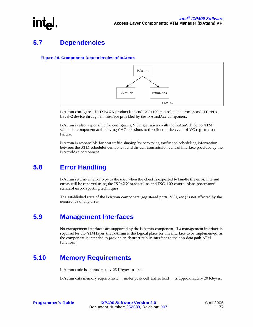
Intel® IXP400 SoftwareAccess-Layer Components: ATM Manager (IxAtmm) API
Programmer’s Guide IXP400 Software Version 2.0 April 2005Document Number: 252539, Revision: 007 77
5.7 Dependencies
IxAtmm configures the IXP4XX product line and IXC1100 control plane processors’ UTOPIA Level-2 device through an interface provided by the IxAtmdAcc component.
IxAtmm is also responsible for configuring VC registrations with the IxAtmSch demo ATM scheduler component and relaying CAC decisions to the client in the event of VC registration failure.
IxAtmm is responsible for port traffic shaping by conveying traffic and scheduling information between the ATM scheduler component and the cell transmission control interface provided by the IxAtmdAcc component.
5.8 Error HandlingIxAtmm returns an error type to the user when the client is expected to handle the error. Internal errors will be reported using the IXP4XX product line and IXC1100 control plane processors’ standard error-reporting techniques.
The established state of the IxAtmm component (registered ports, VCs, etc.) is not affected by the occurrence of any error.
5.9 Management InterfacesNo management interfaces are supported by the IxAtmm component. If a management interface is required for the ATM layer, the IxAtmm is the logical place for this interface to be implemented, as the component is intended to provide an abstract public interface to the non-data path ATM functions.
5.10 Memory RequirementsIxAtmm code is approximately 26 Kbytes in size.
IxAtmm data memory requirement — under peak cell-traffic load — is approximately 20 Kbytes.
Figure 24. Component Dependencies of IxAtmm
IxAtmm
IxAtmSch IAtmDAcc
B2294-01

Intel® IXP400 SoftwareAccess-Layer Components: ATM Manager (IxAtmm) API
April 2005 IXP400 Software Version 2.0 Programmer’s Guide78 Document Number: 252539, Revision: 007
5.11 PerformanceThe IxAtmm does not operate on the data path of the IXP4XX product line and IXC1100 control plane processors. Because it is primarily concerned with registration and deregistration of port and VC data, IxAtmm is typically executed during system initialization.

Intel® IXP400 Software
Programmer’s Guide IXP400 Software Version 2.0 April 2005Document Number: 252539, Revision: 007 79
Access-Layer Components:ATM Transmit Scheduler (IxAtmSch) API 6
This chapter describes the Intel® IXP400 Software v2.0’s “ATM Transmit Scheduler” (IxAtmSch) access-layer component.
6.1 What’s NewThere are no changes or enhancements to this component in software release 2.0.
6.2 OverviewIxAtmSch is an “example” software release 2.0 component, an ATM scheduler component supporting ATM transmit services on IXP4XX product line and IXC1100 control plane processors.
This chapter discusses the following IxAtmSch component details:
• Functionality and services
• Interfaces to use the services
• Conditions and constraints for using the services
• Component dependencies on other IXP400 software components
• Component performance and resource usage estimates
IxAtmSch is a simplified scheduler with limited capabilities. See Table 9 on page 80 for details of scheduler capabilities.
The IxAtmSch API is specifically designed to be compatible with the IxAtmdAcc transmission-control interface. However, if a client decides to replace this scheduler implementation, they are urged to reuse the API presented on this component.
IxAtmSch conforms to interface definitions for the IXP4XX product line and IXC1100 control plane processors’ ATM transmission-control schedulers.
6.3 IxAtmSch Component FeaturesThe IxAtmSch component is provided as a demonstration ATM scheduler for use in the processor’s ATM transmit. It provides two basic services for managing transmission on ATM ports:
• Outbound (transmission) virtual connection admission control on serving ATM ports

Intel® IXP400 SoftwareAccess-Layer Components: ATM Transmit Scheduler (IxAtmSch) API
April 2005 IXP400 Software Version 2.0 Programmer’s Guide80 Document Number: 252539, Revision: 007
• Schedule table to the ATM transmit function that will contain information for ATM cell scheduling and shaping
IxAtmSch implements a fully operational ATM traffic scheduler for use in the processor’s ATM software stack. It is possible (within the complete IXP400 software architecture) to replace this scheduler with one of a different design. If replaced, this component still is valuable as a model of the interfaces that the replacement scheduler requires to be compatible with the IXP400 software ATM stack. IxAtmSch complies with the type interfaces for an IXP400 software compatible ATM scheduler as defined by the IxAtmdAcc software component.
The IxAtmSch service model consists of two basic concepts: ATM port and VCC. Instead of dealing with these real hardware and software entities in the processor and software stack, IxAtmSch models them. Because of this, there is no limit to how many ATM ports it can model and schedule — given enough run-time computational resources.
IxAtmSch does not currently model or schedule Virtual Paths (VPs) or support any VC aggregation capability.
In order to use IxAtmSch services, a client first must ask IxAtmSch to establish the model for an ATM port. Virtual connections then can be attached to the port.
IxAtmSch models the virtual connections and controls the admission of a virtual connection, based on the port model and required traffic parameters. IxAtmSch schedules and shapes the outbound traffic for all VCs on the ATM port. IxAtmSch generates a scheduling table detailing a list of VCs and number of cells of each to transmit in a particular order.
The IxAtmSch component’s two basic services are related. If a VC is admitted on the ATM port, IxAtmSch is committed to schedule all outbound cells for that VC, so that they are conforming to the traffic descriptor. The scheduler does not reject cells for transmission as long as the transmitting user(s) (applications) do not over-submit. Conflict may happen on the ATM port because multiple VCs are established to transmit on the port.
If a scheduling commitment cannot be met for a particular VC, it is not be admitted. The IxAtmSch component admits a VC based only on the port capacity, current-port usage, and required-traffic parameters.
The current resource requirements are for a maximum of eight ports and a total of 32 VCs across all ports. This may increase in the future.
Table 9 shows the ATM service categories that are supported in the current scheduler model.
Table 9. Supported Traffic Types
Traffic Type Supported Num VCs CDVT PCR SCR MCR MBS
rt-VBR Yes Single VC per port Yes Yes† Yes No Yes
nrt-VBR Yes Single VC per port No Yes Yes No No
UBR Yes Up to 32 VC No Yes No No No
CBR Yes — simulated
Single VC per port Yes Yes = PCR No No
† This scheduler implementation is special purpose and assumes SCR = PCR.†† The CDVT does not comply with the ATM-TM-4.1 standard.
Intel® IXP400 SoftwareAccess-Layer Components: ATM Transmit Scheduler (IxAtmSch) API
Programmer’s Guide IXP400 Software Version 2.0 April 2005Document Number: 252539, Revision: 007 81
6.4 Connection Admission Control (CAC) FunctionIxAtmSch makes outbound virtual connection admission decisions based a simple ATM port reference model. Only one parameter is needed to establish the model: outbound (upstream) port rate R, in terms of (53 bytes) ATM cells per second.
IxAtmSch assumes that the “real-world” ATM port is a continuous pipe that draws the ATM cells at the constant cell rate. IxAtmSch does not rely on a hardware clock to get the timing. Its timing information is derived from the port rate. It assumes T = 1/R seconds pass for sending every ATM cell.
IxAtmSch determines if a new (modeled) VC admission request on any ATM port is acceptable using the following information supplied by its client:
• Outbound port rate
• Required traffic parameters for the new VC
• Traffic parameters of existing VCs on that port
IxAtmSch works on a first-come-first-served basis. For example, if three existing CBR VCs on the ATM port each use one-fourth of the port’s capacity (PCR = R/4), the fourth CBR VCC asking for 1/3 of the port capacity (PCR = R/3) will be rejected. IxAtmSch issues a globally unique VCC ID for each accepted VCC.
For non-CBR real time VCs — where the SCR and PCR values are different — only the SCR value is used to determine the required capacity for the VC. This is based on the principle that, over a long term, the required capacity of the VC will be equal to the SCR value, even if the VC may burst at rates above that rate for short periods.
Upon a successful registration via the CAC function, each VC is issued a port-unique identifier value. This value is a positive integer. This value is used to identify the VC to IxAtmSch during any subsequent calls. The combination of port and VC ID values will uniquely identify any VC in the processor device to the IxAtmSch component.

Intel® IXP400 SoftwareAccess-Layer Components: ATM Transmit Scheduler (IxAtmSch) API
April 2005 IXP400 Software Version 2.0 Programmer’s Guide82 Document Number: 252539, Revision: 007
6.5 Scheduling and Traffic Shaping
6.5.1 Schedule TableOnce an ATM port is modeled and VCs are admitted on it, the client can request IxAtmSch to publish the schedule table that indicates how the cells — on all modeled VCs over the port — will be interleaved and transmitted.
IxAtmSch publishes a scheduling table each time its scheduling function is called by a client for a particular port. The schedule table data structure returned specifies an ordering on which cells should be transmitted from each VCs on the port for a forthcoming period. The client is expected to requests a table for a port when the transmit queue is low on that port.
The number of cells that are scheduled by each call to the scheduling function will vary depending on the traffic conditions. The schedule table contains an element, totalCellSlots, which specifies how many cell slots are scheduled in this table returned, including idle cells.
When the client calls the schedule function, the scheduler assumes that all previously scheduled cells on this port have been transmitted and that it may overwrite the previous schedule table with the new table. The client, therefore, must not be dependent on the integrity of the previous table when a request is made for a new schedule table. Additionally, the client should ensure that the current schedule table has been processed by the transmit mechanism before it requests for a new table.
Figure 25. Multiple VCs for Each Port, Multiplexed onto Single Line by the ATM Scheduler
IxAtmSch Component
VC 2Port 2
VC 4Port 3
Schedule Table forPORT 1
VC 1Port 1
Schedule Table forPORT 2
Schedule Table forPORT 3
VC 3Port 1
VC 5Port 1
VC 6Port 2
VCs submit demandfor transmit of ATM
cells.
IxAtmSch componentdetermines when toschedule each cell
on the physical port.
Cells are queued fortransmission on eachport based on thisschedule table, suchthat all traffic contractsare fulfilled.
B2298-01

Intel® IXP400 SoftwareAccess-Layer Components: ATM Transmit Scheduler (IxAtmSch) API
Programmer’s Guide IXP400 Software Version 2.0 April 2005Document Number: 252539, Revision: 007 83
The schedule table is composed of an array of table entries, each of which specifies a VC ID and a number of cells to transmit from that VC. The scheduler explicitly inserts idle cells into the table, where necessary, to fulfill the traffic contract of the VCs registered in the system. Idle cells are inserted in the table with the VC identifier set to 0.
The exact format of the schedule table is defined in IxAtmTypes.h.
Figure 26 shows how this table is translated into an ordered sequence of cells transmitted to the ATM port.
6.5.1.1 Minimum Cells Value (minCellsToSchedule)
When a port model is created the minimum number of cells (minCellstoSchedule) that the scheduler should schedule per table is specified. Therefore, as long as there is at least one cell available to schedule the scheduler will guarantee to generate a table containing a minimum totalCellSlots value of minCellsToSchedule. If the number of outstanding cells available for scheduling is less than minCellsToSchedule, idle cells are scheduled to make up the difference. This value is setup once per port and cannot be modified.
Note: The minCellstoSchedule facility is provided to simplify the transmission control code in the case where queue threshold values are used to drive scheduling. The threshold value in cells can be matched to the minCellsToSchedule so that scheduler is always guaranteed to schedule enough cells to fill the Tx Q above its threshold value.
6.5.1.2 Maximum Cells Value (maxCells)
The maximum number of cells that the scheduler produces in a table can be limited by the maxCells parameter. This can controllable on a table by table basis. The actual number of cells scheduled will be the lesser of maxCells and minCellsToSchedule.
6.5.2 Schedule Service ModelIxAtmSch provides schedule service through two functional interfaces: “VC queue update” and “Schedule table update.”
Figure 26. Translation of IxAtmScheduleTable Structure to ATM Tx Cell Ordering
IxAtmScheduleTableEntry[]
vcUserConnId: 0numberOfCells: 12
vcUserConnId: 2numberOfCells: 24
vcUserConnId: 1numberOfCells: 13
vcUserConnId: 2numberOfCells: 31
vcUserConnId: 1numberOfCells: 20tableSize: 5
totalCellSlots: 9
IxAtmScheduleTable
table:*ptr
Cells transmitted on the ATM linein the order specified, numberedby vcUserConnId. (0 indicates
idle cell)
112220122
ATM TxB2301-01

Intel® IXP400 SoftwareAccess-Layer Components: ATM Transmit Scheduler (IxAtmSch) API
April 2005 IXP400 Software Version 2.0 Programmer’s Guide84 Document Number: 252539, Revision: 007
The client calls the VC queue update interface whenever the user of the VC submits cells for transmission. The structure of the VC queue update interface is compatible with the requirements of the IxAtmdAcc component.
The client calls the schedule-table-update interface whenever it needs a new table. Internally, IxAtmSch maintains a transmit queue for each VC.
IxAtmSch also provides a “VC queue clear” interface for use when the client wishes to cancel pending demand on a particular VC. This interface is useful, for example, when the client wishes to remove a VC from the system.
6.5.3 Timing and Idle CellsIxAtmSch does not rely on a hardware clock for timing. Instead, the component derives timing information from the supplied port transmit rate for each modeled ATM port. IxAtmSch assumes that T = 1/R seconds pass for sending every ATM cell. IxAtmSch also assumes that all cells scheduled in a schedule table are transmitted immediately following the cells previously scheduled by the scheduler on that port. (No cells — other than those scheduled by IxAtmSch — are being transmitted on the port.)
The client is responsible for calling “update table” in the following timely fashion, if the demand is always there. Suppose the “update table” calls for a port corresponds to time spending T(1), T(2),…, where one T(n) is the time needed to transmit cells scheduled in the n’th updated table. Then, if the demand is always there, the client must call the n’th “update table” before T(1)+T(2)+…+T(n-1) has passed, assuming the client’s first such call is at time 0. This can be easily achieved by making sure that port transmission is never empty when the demand is continuously pouring in.
When all registered VC transmit queues are exhausted, an empty schedule table is returned by the ixAtmSchTableUpdate interface. It is assumed that the client will instruct the lower layers to transmit idle cells until new cells are submitted for transmit on a registered VC. IxAtmSch is not aware of the number of idle cells transmitted in this situation and will reset its internal clock to its starting configuration when new cells are queued.
A further interface is provided to allow the client to update the transmit port rate of an ATM port which has already been registered with the IxAtmSch device, and may have established VCs with pending transmit demand. This interface is provided to cater for the event of line-rate drift, as can occur on transmit medium.
In the event that the new port rate is insufficient to support all established VC transmit contracts, IxAtmSch will refuse to perform this modification. The client is expected to explicitly remove or modify some established VC in this event, such that all established contracts can be maintained and then resubmit the request to modify the ATM port transmit rate.
Note: If UBR VCs are registered and they specify a PCR that is based on the initial line rate and the line rate subsequently changes to below the PCR values supplied for the UBR connections, the scheduler will still allow the port rate change.
6.6 DependenciesThe IxAtmSch component has an idealized local view of the system and is not dependent on any other IXP400 software component.

Intel® IXP400 SoftwareAccess-Layer Components: ATM Transmit Scheduler (IxAtmSch) API
Programmer’s Guide IXP400 Software Version 2.0 April 2005Document Number: 252539, Revision: 007 85
Some function interfaces supplied by the IXP400 software component adhere to structure requirements specified by the IxAtmdAcc component. However, no explicit dependency exists between the IxAtmSch component and the IxAtmdAcc component.
6.7 Error HandlingIxAtmSch returns an error type to the user when the client is expected to handle the error. Internal errors will be reported using standard processor error-reporting techniques.
6.8 Memory RequirementsMemory estimates have been sub-divided into two main areas: performance critical and not performance critical.
6.8.1 Code SizeThe ixAtmSch code size is approximately 35 Kbytes.
6.8.2 Data MemoryThere are a maximum of 32 VCs per port and eight ports supported by the IxAtmSch component. These multipliers are used in Table 10.
6.9 PerformanceThe key performance measure for the IxAtmSch component is the rate at which it can generate the schedule table, measured by time per cell. The rate at which queue updates are performed is also important. As this second situation will happen less frequently, however — because a great many cells may be queued in one call to the update function — it is of secondary importance.
The remaining functionality provided by the IxAtmSch is infrequent in nature, being used to initialize or modify the configuration of the component. This situation is not performance-critical as it does not affect the data path of the IXP42X product line processors.
Table 10. IxAtmSch Data Memory Usage
Per VC Data Per Port Data Total
Performance Critical Data 36 44 + (32 * 36) = 1,196 9,568
Non Critical Data 40 12 + (40 * 32) = 192 10,336
Total 76 2,488 19,904

Intel® IXP400 SoftwareAccess-Layer Components: ATM Transmit Scheduler (IxAtmSch) API
April 2005 IXP400 Software Version 2.0 Programmer’s Guide86 Document Number: 252539, Revision: 007
6.9.1 LatencyThe transmit latency introduced by the IxAtmSch component into the overall transmit path of the processor will be zero under normal operating conditions. This is due to the fact that — when traffic is queued for transmission — scheduling will be performed in advance of the cell slots on the physical line becoming available to transmit the cells that are queued.

Intel® IXP400 Software
Programmer’s Guide IXP400 Software Version 2.0 April 2005Document Number: 252539, Revision: 007 87
Access-Layer Components:Security (IxCryptoAcc) API 7
This chapter describes the Intel® IXP400 Software v2.0’s “Security API” IxCryptoAcc access-layer component.
The Security Hardware Accelerator access component (IxCryptoAcc) provides support for authentication and encryption/decryption services needed in cyrptographic applications, such as IPSec authentication and encryption services, SSL or WEP. Depending on the cryptographic algorithm used, cryptography clients can offload the task of encryption/decryption from the Intel XScale core by using the crypto coprocessor. Clients can also offload the task of authentication by using the hashing coprocessor.
7.1 What’s NewThere are no changes to this component in software release 2.0. However, the API has been enhanced by the creation of a new function alias.
ixCryptoAccHashPerform() has been added to help clarify that the API can be used to generate a generic SHA1 or MD5 hash value. This function is aliased to ixCryptoAccHashKeyGenerate().
7.2 OverviewThe IxCryptoAcc component provides the following major capabilities:
• Operating modes:
— Encryption only
— Decryption only
— Authentication calculation only
— Authentication check only
— Encryption followed by authentication calculation (for IPSec and WEP clients)
— Authentication check followed by decryption (for IPSec and WEP clients)
• Cryptographic algorithms:
— DES (64-bit block cipher size, 64-bit key)
— Triple DES (64-bit block cipher size; three keys, 56-bit + 8-bit parity each = 192 bits total)
— AES (128-bit block cipher size; key sizes: 128-, 192-, 256-bit)
— ARC4 (8-bit block cipher size, 128-bit key)
• Μode of operation for encryption and decryption:
— NULL (for stream ciphers, like ARC4)

Intel® IXP400 SoftwareAccess-Layer Components: Security (IxCryptoAcc) API
April 2005 IXP400 Software Version 2.0 Programmer’s Guide88 Document Number: 252539, Revision: 007
— ECB
— CBC
— CTR (for AES algorithm only)
— Single-Pass AES-CCM encryption and security for 802.11i.
• Authentication algorithms:
— HMAC-SHA1 (512-bit data block size, from 20-byte to 64-byte key size)
— HMAC-MD5 (512-bit data block size, from 16-byte to 64-byte key size)
— SHA1/MD5 (basic hashing functionality)
— WEP ICV generation and verification using the 802.11 WEP standard 32-bit CRC polynomial.
• Supports a maximum of 1,000 security associations (tunnel) simultaneously. (A Security Association [SA] is a simplex “connection” that affords security services to the traffic carried by it.)
7.3 IxCryptoAcc API ArchitectureThe IxCryptoAcc API is an access-layer component that provides cryptographic services to a client application. This section describes the overall architecture of the API. Subsequent sections describe the component parts of the API in more detail and describe usage models for the IxCrypto API.
7.3.1 IxCryptoAcc InterfacesIxCryptoAcc is the API that provides cyrptography acceleration features in software release 2.0. This API contains functions that can generally be grouped into two distinct “services.” One service is for IPSec-type cryptography protocols that utilize a combination of encryption (e.g., 3DES or AES) and/or authentication processing (e.g., SHA-1, MD5) in a variety of different operating modes (ECB, CBC, etc.). Throughout this document, the term “IPSec client” is used to refer to the type of application that uses the IxCryptoAcc API in this manner. There are specific API features to support this type of client.
The second service type is designed for 802.11-based WEP security client implementations. The IxCryptoAcc API provides specific features that perform WEP ICV generation and ARC4 stream cipher encryption and decryption. The “WEP services” in the API are used by “WEP clients”.
Secure Sockets Layer (SSL) and Transport Layer Security (TLS) protocol clients can use some of the features of both types of services.
The IPSec and WEP clients are application-level code executing on the Intel XScale core that utilize the services provided by IxCryptoAcc. In this software release, the IxCryptoAccCodelet is provided as an example of client software.
The API utilizes a number of other access-layer components, as well as hardware-based acceleration functionality available on the NPEs and Intel XScale core. Figure 27 on page 90 shows the high-level architecture of IxCryptoAcc.

Intel® IXP400 SoftwareAccess-Layer Components: Security (IxCryptoAcc) API
Programmer’s Guide IXP400 Software Version 2.0 April 2005Document Number: 252539, Revision: 007 89
The Intel XScale core WEP Engine is a software-based “engine” for performing ARC4 and WEP ICV calculations used by WEP clients. While this differs from the model of NPE-based hardware acceleration typically found in the IXP400 software, it provides additionally design flexibility for products that require NPE A to perform non-crypto operations.
IxQMgr is another access-layer component that interfaces to the hardware-based AHB Queue Manager (AQM). The AQM is SRAM memory used to store pointers to data in SDRAM memory, which is accessible by both the Intel XScale core and the NPEs. These items are the mechanism by which data is transferred between IxCryptoAcc and the NPEs. Separate hardware queues are used for both IPSec and WEP services.
The NPEs provide hardware acceleration for IxCryptoAcc. Specifically, AES, DES, and hashing acceleration can be provided by NPE C. NPE A offers ARC4 and WEP ICV CRC acceleration.
Note: CryptoAcc access-component layer provides APIs that are generic for all applications that need to perform encryption and authentication operations. In this chapter IPSec is used as one of the example that makes use our cryptoAcc access-layer API to perform the authentication and encryption operations needed for implementation of IPSec
7.3.2 Basic API FlowThis section describes a high-level flow of the IxCryptoAcc API. A more detailed example of API usage is provided in a subsequent section.
The flow of the API is similar for both IPSec and WEP services. The client application initializes the IxCryptoAcc API and then defines the cryptographic contexts (which describe the cryptographic processing type, mode, direction, and a pointer back to the client application callback) necessary for the type of data the client will be submitting to the API. Packets for encryption/decryption and/or authentication are prepared by the client and passed to the IxCryptoAcc component using a “Perform” function of the API, referencing a particular cryptographic context for each packet. IxCryptoAcc invokes IxQMgr to instruct the NPEs to gather the data and appropriate crypto context information from SDRAM.
The NPE (or Intel XScale core WEP Engine) performs encryption/decryption and authentication using the appropriate acceleration component. The resulting data is stored back into the SDRAM. At this point, a previously registered callback will be executed (in most cases), giving the execution context back to the client application.
The IxCryptoAcc component depends on the IxQMgr component to configure and use the hardware queues to access the NPE.
The basic API flow described above is shown in Figure 27.

Intel® IXP400 SoftwareAccess-Layer Components: Security (IxCryptoAcc) API
April 2005 IXP400 Software Version 2.0 Programmer’s Guide90 Document Number: 252539, Revision: 007
7.3.3 Context Registration and the Cryptographic Context DatabaseThe IxCryptoAcc access component supports up to 1,000 simultaneous security association (SA) tunnels. While the term SA is well-known in the context of IPSec services, the IxCryptoAcc component defines these security associations more generically, as they can be used for WEP services as well. Depending upon the application's requirements, the maximum active tunnels supported by IxCryptoAcc access-layer component can be changed by the client. The number of active tunnels will not have any impact on the performance, but will have an impact on the memory needed to keep the crypto context information. The memory requirement will depend on the number of tunnels.
Each cryptographic “connection” is defined by registering it as a cryptographic context containing information such as algorithms, keys, and modes. Each of these connections is given an ID during the context registration process and stored in the Cryptographic Context Database. The information stored in the CCD is stored in a structure detailed below, and is used by the NPE or Intel XScale core WEP Engine to determine the specific details of how to perform the cryptographic processing on submitted data.
Figure 27. Basic IxCryptoAcc API Flow
AHB Queue Manager (AQM)
Intel XScale®
Corez
B2320-02
IXP4XX North AHBBus
NPE A
AAL Co-Processor(for CRC
acceleration)
NPE C
DESCo-Processor
HashingCo-Processor
AESCo-Processor
IPSec ClientPerformCallback
WEP ClientPerformCallback
Access Layer
Authentication/Encryption/Decryption Request
Callback executed uponoperation completeCommunication betw eenaccess component andNPE via AQM
Client
Access-Layer ComponentCo-Processor
IxQMgr
IxCryptoAccIntel XScaleWEP Engine

Intel® IXP400 SoftwareAccess-Layer Components: Security (IxCryptoAcc) API
Programmer’s Guide IXP400 Software Version 2.0 April 2005Document Number: 252539, Revision: 007 91
The context-registration process creates the structures within the CCD, but the crypto context for each connection must be previously defined in an IxCryptoAccCtx structure. The IxCryptoAccCtx structure contains the following information:
• The type of operation for this context. For example, encrypt, decrypt, authenticate, encrypt and authenticate, etc.
• Cipher parameters, such as algorithm, mode, and key length
• Authentication parameters, such as algorithm, digest length, and hash length
• In-place versus non-in-place operation. In-place operation means the once the cryto processing of the source data is completed, the resulting data is placed onto the same IX_MBUF as it was read from.
When the client performs calls the ixCryptoAccCtxRegister() function, the following data must be provided or received:
• The client provides a pointer to the crypto context (i.e., SA definition) being registered.
• The client is required to allocate two IX_MBUFs to the hardware accelerator will populate with the primary and secondary chaining variables.
• The client must register two callbacks. One callback is executed upon the completion of the registration function, the second is executed each time a cryptographic procedure (“perform” functions) has completed on the NPE for this context. There is one exception for the perform callback function, noted in section “ixCryptoAccXscaleWepPerform()” on page 108.
• The function returns a context ID upon successful registration in the CCD.
Figure 28 on page 92 shows the IxCryptoAcc API call process flow that occurs when registering security associations within the CCD. This process is identical for both IPSec and WEP services except in situations where NPE-based acceleration will not be used, such as when using WEP services using only the Intel XScale core WEP engine. For more detailed information on this usage model see “ixCryptoAccXscaleWepPerform()” on page 108.
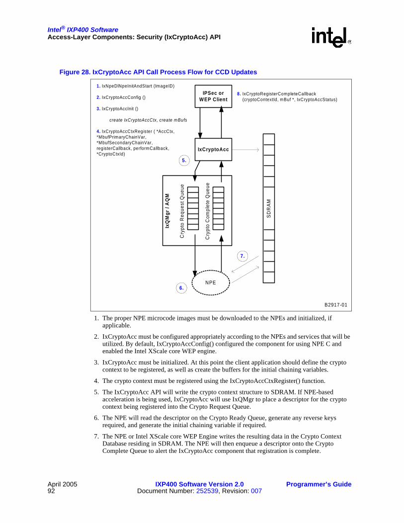
Intel® IXP400 SoftwareAccess-Layer Components: Security (IxCryptoAcc) API
April 2005 IXP400 Software Version 2.0 Programmer’s Guide92 Document Number: 252539, Revision: 007
1. The proper NPE microcode images must be downloaded to the NPEs and initialized, if applicable.
2. IxCryptoAcc must be configured appropriately according to the NPEs and services that will be utilized. By default, IxCryptoAccConfig() configured the component for using NPE C and enabled the Intel XScale core WEP engine.
3. IxCryptoAcc must be initialized. At this point the client application should define the crypto context to be registered, as well as create the buffers for the initial chaining variables.
4. The crypto context must be registered using the IxCryptoAccCtxRegister() function.
5. The IxCryptoAcc API will write the crypto context structure to SDRAM. If NPE-based acceleration is being used, IxCryptoAcc will use IxQMgr to place a descriptor for the crypto context being registered into the Crypto Request Queue.
6. The NPE will read the descriptor on the Crypto Ready Queue, generate any reverse keys required, and generate the initial chaining variable if required.
7. The NPE or Intel XScale core WEP Engine writes the resulting data in the Crypto Context Database residing in SDRAM. The NPE will then enqueue a descriptor onto the Crypto Complete Queue to alert the IxCryptoAcc component that registration is complete.
Figure 28. IxCryptoAcc API Call Process Flow for CCD Updates
IPSec orWEP Client
1. IxNpeDlNpeInitAndStart (ImageID)
2. IxCryptoAccConfig ()
3. IxCryptoAccInit ()
create IxCryptoAccCtx, create mBufs
4. IxCryptoAccCtxRegister ( *AccCtx,*MbufPrimaryChainVar,*MbufSecondaryChainVar,registerCallback, performCallback,*CryptoCtxId)
IxQ
Mgr
/ A
QM
NPE
IxCryptoAcc
Cry
pto
Req
uest
Que
ue
Cry
pto
Com
plet
e Q
ueue
SDR
AM
5.
6.
7.
8. IxCryptoRegisterCompleteCallback (cryptoContextId, mBuf *, IxCryptoAccStatus)
B2917-01

Intel® IXP400 SoftwareAccess-Layer Components: Security (IxCryptoAcc) API
Programmer’s Guide IXP400 Software Version 2.0 April 2005Document Number: 252539, Revision: 007 93
8. IxCryptoAcc will return a context Id to the client application upon successful context registration, and will call the Register Complete callback function.
7.3.4 Buffer and Queue ManagementThe IX_OSAL_MBUF buffer format is for use between the IxCryptoAcc access component and the client. All buffers used between the IxCryptoAcc access component and clients are allocated and freed by the clients. The client will allocate the IX_OSAL_MBUFs and the buffers will be passed to IxCryptoAcc. The CryptoAcc access-layer component will allocate memory for the CCD. The client passes a buffer to IxCryptoAcc when it requests hardware-accelerator services, and the IxCryptoAcc component returns the buffer to the client when the requested job is done.
The component assumes that the allocated IX_OSAL_MBUFs are sufficient in length and no checking has been put in place for the IX_MBUF length within the IX_OSAL_MBUF structure. There is, however, IX_MBUF checking when the code is compiled in DEBUG mode. When appending the ICV at the end of the payload, it is assumed that the IX_OSAL_MBUF’s length is sufficient and will not cause memory segmentation. The ICV offset should be within the length of the IX_MBUF.
Depending on the transfer mode in-place before returning the buffer to the client, the encrypted / decrypted payload is written into the source buffer or destination buffer. This selection of in-place versus non-in-place buffer operation may be defined for each crypto context prior to context registration.
When the AHB Queue Manager is full, the hardware accelerator will return IX_CRYPTO_ACC_QUEUE_FULL to the client. The client will have to re-send the data to be encrypted or decrypted or authenticated after a random interval.
7.3.5 Memory RequirementsThis section shows the amount of data memory required by IxCryptoAcc for it to operate under peak call-traffic load. The IxCryptoAcc component allocates its own memory for the CCD to store the required information, and for the NPE queue descriptors required when using NPE-based acceleration. The total memory allocation follows this general formula:
Total Memory Allocation = (Size of NPE queue descriptor + size of additional authentication data) * Number of descriptors + (size of crypto context) * (number of crypto contexts).
This shows the memory requirements for 1,000 security associations, the default value set by IX_CRYPTO_ACC_MAX_ACTIVE_SA_TUNNELS. This value can be increased or decreased as needed by the client.
Table 11. IxCryptoAcc Data Memory Usage (Sheet 1 of 2)
Structure Size in Bytes Total Size in Bytes
NPE Queue Descriptor 96
Additional Authentication Data 64
Total Memory per NPE Descriptor 96+64=160
Number of NPE Descriptors 278
Total Memory Allocated for NPE Descriptors 160 * 278= 44,480
Crypto Context 152

Intel® IXP400 SoftwareAccess-Layer Components: Security (IxCryptoAcc) API
April 2005 IXP400 Software Version 2.0 Programmer’s Guide94 Document Number: 252539, Revision: 007
7.3.6 DependenciesFigure 29 shows the component dependencies of the IxCryptoAcc component.
Figure 29 can be summarized as follows:
• Client component will call IxCryptoAcc for cryptographic services. NPE will perform the encryption, decryption, and authentication process via IxQMgr.
Number of Crypto Context (IX_CRYPTO_ACC_MAX_ACTIVE_SA_TUNNELS) 1,000
Total Memory Allocated for Crypto Contexts 152 * 1000= 152,000
Size of KeyCryptoParam Structures 256
Total memory allocated for KeyCryptoParam Structures 104*256 26624
Total Memory Allocated by IxCryptoAcc 44480 + 152000 +26624= ~218Kbytes
Table 11. IxCryptoAcc Data Memory Usage (Sheet 2 of 2)
Structure Size in Bytes Total Size in Bytes
Figure 29. IxCryptoAcc Component Dependencies
B3835-01
IxCryptoAcc
Queue Manager (QMgr)
OS Abstraction Layer (OSAL)
Client
NPE C(Ethernet NPE B)
A B Component A depends on Component B
IxFeatureCtrl
NPE A (WAN/VOICE NPE)
(WEPEngine)
BA Optional Dependancy
Intel® IXP400 SoftwareAccess-Layer Components: Security (IxCryptoAcc) API
Programmer’s Guide IXP400 Software Version 2.0 April 2005Document Number: 252539, Revision: 007 95
• IxCryptoAcc depends on the IxQMgr component to configure and use the hardware queues to access the NPE.
• OS Abstraction Layer access-component is used for error handling and reporting, IX_OSAL_MBUF handling, endianness handling, mutex handling, and for memory allocation.
• IxFeatureCtrl access-layer component is used to detect the processor capabilities at runtime, to ensure the necessary hardware acceleration features are available for the requested cryptographic context registrations. The IxFeatureCtrl will only issue an warning and will not return any errors if it detects that the hardware acceleration features are not available on the silicon. The client should make sure that they do not use the cryptographic features if a particular version of silicon does not support the cryptographic features.
• In situations where only the Intel XScale core WEP Engine is used, the IxQMgr component is not utilized. Instead, local memory is used to pass context between the IxCryptoAcc API and the Intel XScale core WEP Engine.
After the CCD has been updated, the API can then be used to perform cryptographic processing on client data, for a given crypto context. This service request functionality of the API is described in “IPSec Services” on page 96 and “WEP Services” on page 106.
7.3.7 Other API FunctionalityIn addition to crypto context registration, IPSec and WEP service requests, the IxCryptoAcc API has a number of other features.
• A number of status definitions, useful for determining the cause of registration or cryptographic processing errors.
• The ability to un-register a specific crypto context from the CCD.
• Two status and statistics functions are provided. These function show information such as the number of packets returned with operation fail, number of packets encrypted/ decrypted/authenticated, the current status of the queue, whether the queue is empty or full or current queue length.
• The ability to halt the API.
The two following functions are used in specific situations that merit further explanation.
ixCryptoAccHashKeyGenerate()
This is a generic SHA-1 or MD5 hashing function that takes as input the specification of a basic hashing algorithm, some data and the length of the digest output. There are several useful scenarios for this function.
This function should be used in situations where an HMAC authentication key of greater than 64 bytes is required for a crypto context, and should be called prior to registering that crypto context in the CCD. An initialization vector is supplied as input.
The function can also be used by SSL client applications as part of the SSL protocol MAC generation by supplying the record protocol data as input. ixCryptoAccHashPerform() can perform this type of operation.

Intel® IXP400 SoftwareAccess-Layer Components: Security (IxCryptoAcc) API
April 2005 IXP400 Software Version 2.0 Programmer’s Guide96 Document Number: 252539, Revision: 007
ixCryptoAccCtxCipherKeyUpdate()
This function is called to change the key value of a previously registered context. Key change for a registered context is only supported for CCM cipher mode. This is done in order to quickly change keys for CCM mode, without going through the process of context deregistration and registration. Changes to the key lengths are not allowed for a registered context. This function should only be used if one is invoking cryptographic operations using CCM as cipher mode.
The client should make sure that there are no pending requests on the “cryptoCtxtId” for the key change to happen successfully. If there are pending requests on this context the result of those operations are undefined.
For contexts registered with other modes, the client should unregister and re-register a context for the particular security association in order to change keys and other parameters.
7.3.8 Error HandlingIxCryptoAcc returns an error type to the client and the client is expected to handle the error. Internal errors will be reported using an IxCryptoAcc-specific, error-handling mechanism listed in IxCryptoAccStatus.
7.3.9 EndiannessThe mode supported by this component is both big endian and little endian.
7.3.10 Import and Export of Cryptographic TechnologySome of the cryptographic technologies provided by this software (such as 3DES and AES) may be subjected to both export controls from the United States and import controls worldwide. Where local regulations prohibit, some described modes of operation may be disabled.
7.4 IPSec ServicesThis section describes the way that IxCryptoAcc is used in an IPSec usage model.
7.4.1 IPSec Background and ImplementationWhen deploying IPSec-related applications, the generalized architecture in Figure 30 is used. The figure shows the scope and the roles played by the NPE and the IxCryptoAcc component in an IPSec application.
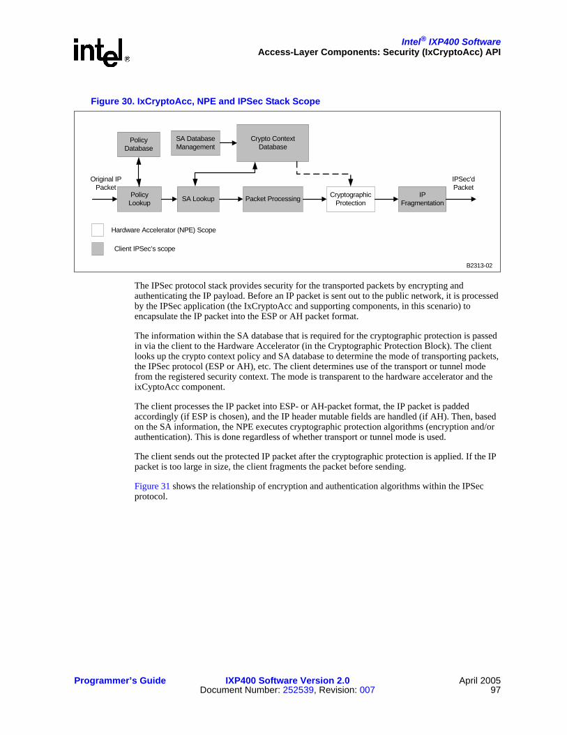
Intel® IXP400 SoftwareAccess-Layer Components: Security (IxCryptoAcc) API
Programmer’s Guide IXP400 Software Version 2.0 April 2005Document Number: 252539, Revision: 007 97
The IPSec protocol stack provides security for the transported packets by encrypting and authenticating the IP payload. Before an IP packet is sent out to the public network, it is processed by the IPSec application (the IxCryptoAcc and supporting components, in this scenario) to encapsulate the IP packet into the ESP or AH packet format.
The information within the SA database that is required for the cryptographic protection is passed in via the client to the Hardware Accelerator (in the Cryptographic Protection Block). The client looks up the crypto context policy and SA database to determine the mode of transporting packets, the IPSec protocol (ESP or AH), etc. The client determines use of the transport or tunnel mode from the registered security context. The mode is transparent to the hardware accelerator and the ixCyptoAcc component.
The client processes the IP packet into ESP- or AH-packet format, the IP packet is padded accordingly (if ESP is chosen), and the IP header mutable fields are handled (if AH). Then, based on the SA information, the NPE executes cryptographic protection algorithms (encryption and/or authentication). This is done regardless of whether transport or tunnel mode is used.
The client sends out the protected IP packet after the cryptographic protection is applied. If the IP packet is too large in size, the client fragments the packet before sending.
Figure 31 shows the relationship of encryption and authentication algorithms within the IPSec protocol.
Figure 30. IxCryptoAcc, NPE and IPSec Stack Scope
PolicyLookup Packet Processing Cryptographic
ProtectionIP
Fragmentation
Crypto ContextDatabase
Original IPPacket
IPSec'dPacket
Hardware Accelerator (NPE) Scope
Client IPSec’s scope
SA Lookup
SA DatabaseManagement
B2313-02
PolicyDatabase

Intel® IXP400 SoftwareAccess-Layer Components: Security (IxCryptoAcc) API
April 2005 IXP400 Software Version 2.0 Programmer’s Guide98 Document Number: 252539, Revision: 007
7.4.2 IPSec Packet FormatsIPSec standards have defined packet formats. The authentication header (AH) provides data integrity and the encapsulating security payload (ESP) provides confidentiality and data integrity. In conjunction with SHA1 and MD5 algorithms, both AH and ESP provide data integrity. The IxCryptoAcc component supports both different modes of authentication. The ICV is calculated through SHA1 or MD5 and inserted into the AH packet and ESP packet.
In ESP authentication mode, the ICV is appended at the end of the packet, which is after the ESP trailer if encryption is required.
Figure 31. Relationship Between IPSec Protocol and Algorithms
ESP AH
EncryptionAlgorithm
AuthenticationAlgorithm
B2307-02
Figure 32. ESP Packet Structure
Security Parameters Index (SPI)
Sequence Number
Payload Data (Variable Length)
Padding (0-255 Bytes)
Pad Length Next Header
Authentication Data (Variable Length)
B2311-02
Encrypted
Authenticated

Intel® IXP400 SoftwareAccess-Layer Components: Security (IxCryptoAcc) API
Programmer’s Guide IXP400 Software Version 2.0 April 2005Document Number: 252539, Revision: 007 99
In AH mode, the ICV value is part of the authentication header. AH is embedded in the data to be protected. This results in AH being included for ICV calculation, which means the authentication data field (ICV value) must be cleared before executing the ICV calculation. The same applies to the ICV verification — the authentication data needing to be cleared before the ICV value is calculated and compared with the original ICV value in the packet. If the ICV values don’t match, authentication is failed.
NPE determines where to insert the ICV value, based on the ICV offset specified in the perform function.
7.4.2.1 Reference ESP Dataflow
Figure 34 shows the example data flow for IP Security environment. Transport mode ESP is used in this example. The IP header is not indicated in the figure.
The IP header is located in front of the ESP header while plain text is the IP payload.
Figure 33. Authentication Header
Security Parameters Index (SPI)
Sequence Number
Payload LengthNext Header
Authentication Data (Variable Length)
(Reserved)
B2312-01

Intel® IXP400 SoftwareAccess-Layer Components: Security (IxCryptoAcc) API
April 2005 IXP400 Software Version 2.0 Programmer’s Guide100 Document Number: 252539, Revision: 007
7.4.2.2 Reference AH Dataflow
Figure 35 shows the example data flow for IP Security environment. Transport mode AH is used in this example. IPSec client handles IP header mutable fields.
Figure 34. ESP Data Flow
Plain text
Plain TextESPHeader
ESPTrailer
Cipher TextESPHeader
ESPTrailer
Encrypt & AuthenticateReq (SA_ID, ...)
Encrypt & AuthenticateReq (SA_ID, ...)
Encyption Operation
Cipher TextESPHeader
ESPTrailer
ESPAuth
Cipher TextESPHeader
ESPTrailer
ESPAuth
Cipher TextESPHeader
ESPTrailer
ESPAuth
Forward authentication Operation
Plain TextESPHeader
ESPTrailer
Application
IPSec Client
Access Component /Intel XScale® Core
NPE
Processed byIPSec client
Processed byNPE
From Application
B2333-02

Intel® IXP400 SoftwareAccess-Layer Components: Security (IxCryptoAcc) API
Programmer’s Guide IXP400 Software Version 2.0 April 2005Document Number: 252539, Revision: 007 101
7.4.3 Hardware Acceleration for IPSec ServicesThe IxCryptoAcc API is dependant upon hardware resources within NPE C (also known as Ethernet NPE B) in order to perform many of the cryptographic encryption, decryption, or authentication functions. Specifically, NPE C provides an AES coprocessor, DES coprocessor and a hashing coprocessor (for MD5 and SHA1 calculations).
7.4.4 IPSec API Call FlowFigure 36 on page 102 details the IxCryptoAcc API call flow that occurs when submitted data for processing using IPSec services. The process listed below assumes that the API has been properly configured and that a crypto context has been created and registered in the CCD, as described in “Context Registration and the Cryptographic Context Database” on page 90.
Figure 35. AH Data Flow
payload
AuthenticateReq (SA_ID, ...)
AuthenticateReq (SA_ID, ...)
Forward authentication Operation
payloadIPHeader
Application
IPSec Client
Access Component /Intel XScale® Core
NPE
Processed byIPSec client
Processed byNPE
From application
IPHeader
AH
payloadIPHeader AH
Note :IP mutable fields arehandled by IPSec client
payloadIPHeader AH Auth
Data
payloadIPHeader AH Auth
Data
payloadIPHeader AH Auth
Data
Note :ICV is inserted into AHauthentication data field
B2460-02

Intel® IXP400 SoftwareAccess-Layer Components: Security (IxCryptoAcc) API
April 2005 IXP400 Software Version 2.0 Programmer’s Guide102 Document Number: 252539, Revision: 007
1. The proper NPE microcode images must have been downloaded to the NPE and initialized. Additionally, the IxCryptoAcc API must be properly configured, initialized, and the crypto context registration procedure must have completed.
At this point, the client must create the IX_OSAL_MBUFs that will hold the target data and populate the source IX_OSAL_MBUF with the data to be operated on. Depending on the encryption/decryption mode being used, the client must supply an initialization vector for the AES or DES algorithm.
2. The client submits the IxCryptoAccAuthCryptPerform() function, supplying the crypto context ID, pointers to the source and destination buffer, offset and length of the authentication and crypto data, offset to the integrity check value, and a pointer to the initialization vector.
3. IxCryptoAcc uses IxQMgr to place a descriptor for the data into the Crypto Request Queue.
Figure 36. IPSec API Call Flow
IPSec Client
1. (...NPE init, CryptoAccConfig,CryptoAccInit, CryptoAccCtxRegister, etc...)
create data mBufs, IV
2. ixCryptoAccAuthCryptPerform (cryptoCtxId, *pSrcMbuf, *pDestMbuf, authStartOffset, authDataLen, cryptStartOffset, cryptDataLen, icvOffset, *pIV)
IxQ
Mgr
/ A
QM
NPE - C
6. IxCryptoPerformCompleteCallback (cryptoContextId, mBuf *, IxCryptoAccStatus)
IxCryptoAccC
rypt
o R
eque
st Q
ueue
Cry
pto
Com
plet
e Q
ueue
SD
RA
M
3.
4.
5.
B2918-01

Intel® IXP400 SoftwareAccess-Layer Components: Security (IxCryptoAcc) API
Programmer’s Guide IXP400 Software Version 2.0 April 2005Document Number: 252539, Revision: 007 103
4. The NPE will read the descriptor on the Crypto Ready Queue and performs the encryption/decryption/authentication operations, as defined in the CCD for the submitted crypto context. The NPE inserts the Integrity Checksum Value (ICV) for a forward-authentication operation and verifies the ICV for a reverse-authentication operation.
5. The NPE writes the resulting data to the destination IX_OSAL_MBUF in SDRAM. This may be the same IX_OSAL_MBUF in which the original source data was located, if the crypto context defined in-place operations. The NPE will then enqueue a descriptor onto the Crypto Complete Queue to alert the IxCryptoAcc component that the perform operation is complete.
6. IxCryptoAcc will call the registered Perform Complete callback function.
7.4.5 Special API Use Cases
7.4.5.1 HMAC with Key Size Greater Than 64 Bytes
As specified in the RFC 2104, the authentication key used in HMAC operation must be at least of L bytes length, where L = 20 bytes for SHA1 or L = 16 bytes for MD5. Authentication key with a key length greater than or equal to ‘L’ and less than or equal to 64 bytes can be used directly in HMAC authentication operation. No further hashing of authentication key is needed. Thus the authentication key can be used directly in crypto context registration.
However, authentication key with key length greater than 64 bytes must be hashed to become L bytes of key size before it can be used in HMAC authentication operation. The authentication key must be hashed before calling crypto context registration API as shown in steps below:
a. Call ixCryptoAccHashKeyGenerate() function and pass in the original authentication key using an IX_MBUF. Also, you will need to register a callback function for when this opera-tion is complete.
b. Wait for callback from IxCryptoAcc.
c. Copy generated authentication key from IX_MBUF into a cryptographic context structure (IxCryptoAccCtx) and call ixCryptoAccCtxRegister() to register the crypto context for this HMAC operation.
7.4.5.2 Performing CCM (AES CTR-Mode Encryption and AES CBC-MAC Authentication) for IPSec
A generic CCM cipher is not supported in the IXP400 software. However, it is possible to perform AES-CCM operations in an IPSec-application style. Single-pass AES-CCM is supported for WEP Services only, as documented in “Counter-Mode Encryption with CBC-MAC Authentication (CCM) for CCMP in 802.11i” on page 112.
The overall strategy to accomplish the AES-CCM request involves two operations. The first operation does the AES-CBC operation to get the CBC-MAC. The second operation is to perform a AES-CTR encryption operation to encrypt the payload and create the CBC-MAC to get the MIC. Two crypto contexts are registered and two crypto perform service requests are invoked in order to complete the encryption and authentication for a packet.
Figure 37 on page 104 and Figure 38 on page 104 show the steps needed to encrypt and authenticate a packet in general by using CCM mode. Those steps are:
1. Use AES CBC-MAC to compute a MIC on plaintext header, and payload.The last cipher block from this operation will become MIC.

Intel® IXP400 SoftwareAccess-Layer Components: Security (IxCryptoAcc) API
April 2005 IXP400 Software Version 2.0 Programmer’s Guide104 Document Number: 252539, Revision: 007
2. Use AES-CTR mode to encrypt the payload with counter values 1, 2, 3, …
3. Use AES-CTR mode to encrypt the MIC with counter value 0 (First key stream (S0) from AES-CTR operation)
The API usage for performing an IPSec-style AES-CCM operation is as follows:
1. Register a crypto context for AES-CBC encryption (cipher context). A crypto context ID (A, in this example) will be obtained in this operation. Non-in-place operation must be chosen (useDifferentSrcAndDestMbufs in IxCryptoAccCtx must set to TRUE) to avoid the original data being overwritten by encrypted data. This crypto context is used only for the purpose of authentication and generating the MIC.
Figure 37. CCM Operation Flow
Legend:E – Encryption operationB – Data blocks to be encrypted (data is split into multiple blocks of the size of cipher block length)S – Key stream generated from AES-CTR encryptionA – Counter blocks for AES-CTR encryptionMIC – Message Integrity Code
Figure 38. CCM Operation on Data Packet
Header Payload MIC
EEE
EEE
A1 ... Am A0
... ...padding padding
B1 … Bk 0 Bk+1 … Br 0
S1 Sm S0...
B0
B3002-01
Header payload MIC
Encrypted
Authenticated
B3003-01

Intel® IXP400 SoftwareAccess-Layer Components: Security (IxCryptoAcc) API
Programmer’s Guide IXP400 Software Version 2.0 April 2005Document Number: 252539, Revision: 007 105
2. Register another crypto context for AES-CTR encryption (cipher context). A crypto context ID (B) will also be obtained in this operation. This crypto context is used for payload and MIC encryption only.
3. After both crypto context registration for both contexts is complete, call the crypto perform API using context ID A. The IV for this packet is inserted as first block of message in the packet. The input IV to the crypto perform function is set to zeroes. Crypt start offset and crypt data length parameters are set to the same values as authentication start offset and authentication data length, as shown in Figure 39 on page 105. Authentication start offset and authentication data length can be ignored in the API for this operation, as this is an encryption operation only. The client should handle all the above-mentioned steps before calling the crypto perform function.
4. Wait for the operation in step 3 to complete and extract the MIC from the destination IX_MBUF using the callback function.
5. Append the MIC from step 4 into the IX_MBUF before the payload data.
6. Call the crypto perform function with crypto context ID B. Change the crypt start offset to point to the start offset of the MIC and change the crypt data length to include the length of MIC, as shown in Figure 40 on page 105.
7. Wait for operation in step 6 to complete and move the MIC back to its original location in IX_MBUF. The MIC is now the final authentication data.
Since the data has to be read twice by the NPE, this two-pass mechanism will have slower throughput rate compared to the other crypto perform operations that combine encryption and authentication.
Note that memory copying is needed when performing the CCM request on a packet as mentioned above. Chained IX_MBUFs could be used to avoid excessive memory copying in order to get better performance. If a single IX_MBUF is used, memory copying is needed to insert MIC from
Figure 39. AES CBC Encryption For MIC
Figure 40. AES CTR Encryption For Payload and MIC
Header Payload
Crypt Data Length(Authentication Data Length)
Original IV
Crypt Start Offset(Authentication Start Offset)
B3004-01
Header PayloadMIC
Crypt Start Offset
Crypt Data Length
B3005-01
Intel® IXP400 SoftwareAccess-Layer Components: Security (IxCryptoAcc) API
April 2005 IXP400 Software Version 2.0 Programmer’s Guide106 Document Number: 252539, Revision: 007
AES-CBC operation into the packet, between header and payload. The payload needs to be moved in order to hold MIC in the packet. An efficient method of doing this could be to split the header and payload into two different IX_MBUFs. Then the MIC can be inserted after the header into the header IX_MBUF for the AES CTR encryption operation.
7.4.6 IPSec Assumptions, Dependencies, and Limitations• Mutable fields in IP headers should be set to a value of 0 by the client.
• The client must pad the IP datagram to be a multiple of the cipher block size, using ESP trailer for encryption (RFC 2406, explicit padding).
• The IxCryptoAcc component handles any necessary padding required during authentication operations, where the IP datagram is not a multiple of the authentication algorithm block size. The NPE pads the IP datagram to be a multiple of the block size, specified by the authentication algorithm (RFC 2402, implicit padding).
• The client must provide an initialization vector to the access component for the DES or AES algorithm, in CBC mode and CTR mode.
• IxCryptoAcc generates the primary and secondary chaining variables which are used in authentication algorithms.
• IxCryptoAcc generates the reverse keys from the keys provided for AES algorithm.
7.5 WEP Services
7.5.1 WEP Background and ImplementationThe Wired Equivalent Privacy (WEP) specification is designed to provided a certain level of security to wireless 802.11 connections at the data-link level. The specification dictates the use of the ARC4 cryptographic algorithm and the use of a CRC-32 authentication calculation (the Integrity Check Value) on the payload and data header.
The IxCryptoAcc API provides both the encryption/decryption and authentication calculation or verification in a single-pass implementation. The API uses two functions for performing WEP service operations, depending on the hardware-acceleration component being utilized. The IxCryptoAcc API features that support a WEP usage model can also be used by client applications to accelerate other cryptography protocols, such as SSL. Refer to “ARC4” on page 111.
ixCryptoAccXScaleWepPerform() is used to submit data for WEP services using the Intel XScale core-based WEP engine.
ixCryptoAccNpeWepPerform() is used to submit data for WEP services using the hardware acceleration services of NPE A.
Both functions operate in a substantially similar manner, taking in the parameters discussed below and shown in Figure 41.

Intel® IXP400 SoftwareAccess-Layer Components: Security (IxCryptoAcc) API
Programmer’s Guide IXP400 Software Version 2.0 April 2005Document Number: 252539, Revision: 007 107
• *pSrcMbuf — a pointer to IX_MBUF, which contains data to be processed. This IX_MBUF structure is allocated by client. Result of this request will be stored in the same IX_MBUF and overwritten the original data if UseDifferentSrcAndDestMbufs flag in IxCryptoAccCtx is set to FALSE (in-place operation). Otherwise, if UseDifferentSrcAndDestMbufs flag is set to TRUE, the result will be written into destination IX_MBUF (non-in-place operation) and the original data in this IX_MBUF will remain unchanged.
• *pDestMbuf — Only used if UseDifferentSrcAndDestMbufs is TRUE. This is the buffer where the result is written to. This IX_MBUF structure is allocated by client. The length of IX_MBUF must be big enough to hold the result of operation. The result of operation cannot span into two or more different IX_MBUFs, thus the IX_MBUF supplied must be at least the length of expected result. The data is written back starting at startOffset in the pDestMbuf.
• startOffset — Supplied by the client to indicate the start of the payload to be decrypted/encrypted or authenticated.
• dataLen — Supplied by the client to indicate the length of the payload to be decrypted/encrypted in number of bytes.
• icvOffset — Supplied by the client to indicate the start of the ICV (Integrity Check Value) used for the authentication. This ICV field should not be split across multiple IX_MBUFs in a chained IX_MBUF.
• *pKey — Pointer to IX_CRYPTO_ACC_ARC4_KEY_128 bytes of per packet ARC4 keys. This pointer can be NULL if the request is WEP IV gen or verify only.
In the figure above, it is assumed for the sake of simplicity that mData is a contiguous buffer starting from byte 0 to the end of the FCS.
FCS is not computed or touched by the component.
7.5.2 Hardware Acceleration for WEP ServicesThe WEP services provided in IxCryptoAcc depend on hardware-based resources for some of the cryptographic functions. This differs from the model of NPE-based hardware acceleration typically found in the IXP400 software in that the client software can select to use NPE-based acceleration or an Intel XScale core-based software engine that both provide equivalent functionality.
Figure 41. WEP Frame with Request Parameters
Frame Header IV Header Frame Body ICV FCS
mData ptr
startOffset dataLen
icvOffset
icv ptr
B2919-01

Intel® IXP400 SoftwareAccess-Layer Components: Security (IxCryptoAcc) API
April 2005 IXP400 Software Version 2.0 Programmer’s Guide108 Document Number: 252539, Revision: 007
These acceleration components provide the following services to IxCryptoAcc:
• ARC4 (Alleged RC4) encryption / decryption
• WEP ICV generation and verification
The API provides two functions for performing WEP operations. ixCryptoAccXScaleWepPerform() is used to submit data for WEP services using the Intel XScale core-based WEP engine. ixCryptoAccNpeWepPerform() is used to submit data for WEP services using the hardware acceleration services of NPE A.
It is important to note that the perform requests are always executed entirely on the specified engine. However, a single crypto context may be submitted to either engine. There are some specific behavioral characteristics for each engine.
ixCryptoAccNpeWepPerform()
The NPE-based WEP perform function acts identically to the IPSec service perform functions in terms of callback behavior. During crypto context registration, a callback is specified to be executed upon completion of the perform operation. For ixCryptoAccNpeWepPerform(), this callback is executed asynchronously. When the NPE has completed the required processing, it will initiate the client callback.
ixCryptoAccXscaleWepPerform()
The WEP perform function using the Intel XScale core WEP engine has two distinct differences from the NPE-based function.
First, ixCryptoAccXscaleWepPerform() operates synchronously. This is to say that once the perform function is submitted, the Intel XScale core function retains the context until the perform operation is complete. The Intel XScale core perform function will not execute the registered performCallback function. The client should initiate any local callback function on its own.
The second behavior difference is that the Intel XScale core perform function does not support non-in-place memory operations.The function returns an error if the non-in-place operation is requested.
NPE Microcode Images
The WEP NPE image IX_NPEDL_NPEIMAGE_NPEA_WEP makes autonomous use of NPE A (also known as the WAN/Voice NPE) and cannot be used simultaneously with any other NPE images on NPE A. Should the product design require NPE A be used for another purpose (DMA or ATM processing, for example), then the Intel XScale core WEP engine should be used.
7.5.3 WEP API Call FlowFigure 42 on page 109 details the IxCryptoAcc API call flow that occurs when submitted data for processing using WEP services. The process listed below assumes that the API has been properly configured and that a crypto context has been created and registered in the CCD, as described in “Context Registration and the Cryptographic Context Database” on page 90.

Intel® IXP400 SoftwareAccess-Layer Components: Security (IxCryptoAcc) API
Programmer’s Guide IXP400 Software Version 2.0 April 2005Document Number: 252539, Revision: 007 109
1. The proper NPE microcode images must have been downloaded to the NPE and initialized. Additionally, the IxCryptoAcc API must be properly configured, initialized, and the crypto context registration procedure must have completed.At this point, the client must create the IX_MBUFs that will hold the target data and populate the source IX_MBUF with the data to be operated on. The client must supply the ARC4 key for the ARC4 algorithm.
2. The client submits the ixCryptoAccNpeWepPerform() or ixCryptoAccXscaleWepPerform() function, supplying the crypto context ID, pointers to the source and destination buffer, offset and length of the authentication and crypto data, offset to the integrity check value, and a pointer to the ARC4 key.
3. IxCryptoAcc will use IxQMgr to place a descriptor for the data into the WEP Request Queue.
Figure 42. WEP Perform API Call Flow
WEP Client
1. (...NPE init, CryptoAccConf ig, CryptoAccInit, CryptoAccCtxRegister,etc...)
create data mBufs, IV
2. ixCryptoAcc*WepPerform (cryptoCtxId, *pSrcMbuf , *pDestMbuf , startOf fset, dataLen, icvOffset, *pKey)
IxQ
Mgr
/ AQ
M
NPE - Aor
Intel® XScaleCore WEP
Engine
6. ixCryptoPerformCompleteCallback (cryptoContextId, mBuf *, IxCryptoAccStatus)
IxCryptoAccW
EP
Req
uest
Que
ue
WE
P C
ompl
ete
Que
ue
SD
RA
M
3.
4.
5.
B2920-01

Intel® IXP400 SoftwareAccess-Layer Components: Security (IxCryptoAcc) API
April 2005 IXP400 Software Version 2.0 Programmer’s Guide110 Document Number: 252539, Revision: 007
4. The NPE will read the descriptor on the Crypto Request Queue and performs the encryption/decryption/authentication operations, as defined in the CCD for the submitted crypto context. The NPE will also insert or verify the WEP ICV integrity check value.
5. The NPE writes the resulting data to the destination IX_MBUF in SDRAM. This may be the same IX_MBUF in which the original source data was located, if the crypto context defined in-place operations. The NPE will then enqueue a descriptor onto the WEP Complete Queue to alert the IxCryptoAcc component that the perform operation is complete.
6. If the ixCryptoAccNpeWepPerform() function was executed in Step 2, IxCryptoAcc will call the registered Perform Complete callback function. Otherwise the client will need initiate any callback-type actions itself.
7.6 SSL and TLS Protocol Usage ModelsSSL version 3 and TLS version 1 protocol clients can use several features provided by the IPSec and WEP services, described in earlier sections of this chapter. SSL and TLS are similar is many ways. The primary difference related to the IxCryptoAcc API is that TLS uses the HMAC (RFC 2104) hashing method for record protocol authentication. SSLv3 uses a keyed hashing mechanism for MAC generation that is similar, but not identical, to the HMAC specification.
Authentication
SSL does not use the HMAC method of MAC generation that is provided with the IxCryptoAcc ixCryptoAccAuthCryptPerform() function. An SSL client can instead use ixCryptoAccHashPerform() for basic SHA-1 or MD-5 hashing capabilities, as part of its MAC calculation activities. Refer to “ixCryptoAccHashKeyGenerate()” on page 95.
TLS clients may use the ixCryptoAccAuthCryptPerform() function for authentication calculation or verification crypto contexts.
Encryption/Decryption
Both protocols can take advantage of the DES-CBC and 3DES-CBC encryption. The CipherSpec value of DES_EDE_CBC in the SSL and TLS protocols refers to the 3DES-CBC operation mode. Both types of clients may use the ixCryptoAccAuthCryptPerform() function for encrypt-only or decrypt-only contexts.
ARC4 Steam Cipher
SSL and TLS clients may use the ARC4 cipher capabilities of the ixCryptoAccNpeWepPerform() and ixCryptoAccXscaleWepPerform() functions. Note that only 128-bit key strength is supported for contexts that do not use WEP-CRC calculation.
Combined Mode Operations
One fundamental difference between SSL / TLS protocols and IPSec operations lies in the order of authenticate and encryption/decryption operations. SSL and TLS protocols generate the MAC prior to encryption (and verify the authentication code after decrypting the message). The IPSec ESP protocol generates its HMAC-based Integrity Check Value (ICV) on the encrypted IP packet payload (and verifies the ICV before decrypting the packet payload).

Intel® IXP400 SoftwareAccess-Layer Components: Security (IxCryptoAcc) API
Programmer’s Guide IXP400 Software Version 2.0 April 2005Document Number: 252539, Revision: 007 111
The ixCryptoAccAuthCryptPerform() functionality described in “IPSec Services” on page 96 offers capabilities to perform encrypt /decrypt AND authentication calculations in one submission for IPSec style clients only. This “single-pass” method does not work for SSL and TLS clients. SSL and TLS clients must register two contexts; one for encryption/decryption only and the other for authentication create / verify.
7.7 Supported Encryption and Authentication Algorithms
7.7.1 Encryption AlgorithmsIxCryptoAcc supports four different ciphering algorithms
• Data Encryption Standard (DES)
• Triple DES
• Advanced Encryption Standard (AES)
• ARC4 (Alleged RC4)
Table 12 summarizes the supported cipher algorithms and the key sizes. The actual key size in DES and 3DES is less because every byte has one parity bit. The parity bit is not used in the encryption process.
The order expected by the Security Hardware Accelerator is in the network byte order (big endian). It is the responsibility of the client to ensure order.
3DES
The order the keys are passed in should be Key 1, Key 2, and Key 3.
ARC4
The ARC4 algorithm can only be used in standalone mode or along with WEP-CRC algorithm. It cannot be combined with any other authentication algorithms, like HMAC-SHA1 and HMAC-MD5. ARC4 keys used in WEP are generally 8 bytes (64-bit) or 16 bytes (128-bit). The ARC4 engine expects to be passed a key of 16 bytes in length, where it then copies the key to fill a 256-byte buffer. Therefore, if the key being used by the client is 8 bytes long, then the client should repeat it to fill the 16 bytes of key buffer.
Table 12. Supported Encryption Algorithms
Cipher Algorithm
Key Sizes (Bits)
Parity Bit(Bits)
Actual Key Size (Bits)
Plaintext / Ciphertext Block Size (Bits)
DES 64 8 56 64
3DES 192 24 168 64
AES128192256
NA128192256
128
ARC4 128 NA 128 8

Intel® IXP400 SoftwareAccess-Layer Components: Security (IxCryptoAcc) API
April 2005 IXP400 Software Version 2.0 Programmer’s Guide112 Document Number: 252539, Revision: 007
SSL client applications can make use of the ARC4 processing features by registering an encryption-only or decryption-only crypto context and the IxCryptoAccXScaleWepPerform() or IxCryptoAccNpeWepPerform() functions. SSL clients should supply a full 128-bit key to the API.
7.7.2 Cipher ModesThere are four cipher modes supported by the NPE:
• Electronic code book (ECB)
• Cipher block chaining (CBC)
• Counter Mode (CTR)
• Counter-Mode / CBC-MAC Protocol (CCMP)
7.7.2.1 Electronic Code Book (ECB)
The ECB mode for encryption and decryption is supported for DES, Triple DES and AES. ECB is a direct application of the DES algorithm to encrypt and decrypt data.
When using the DES in ECB mode and any particular key, each input is mapped onto a unique output in encryption and this output is mapped back onto the input in decryption. The DES is an iterative, block, product-cipher system (that is, encryption algorithm). A product-cipher system mixes transposition and substitution operations in an alternating manner.
7.7.2.2 Cipher Block Chaining (CBC)
The CBC mode for encryption and decryption is supported for DES, Triple DES, and AES. It requires initialization vector (IV) of size 64-bit for DES and 128-bit for AES initialization vector (IV).
7.7.2.3 Counter Mode (CTR)
The counter mode (CTR) is only applicable for AES. The counter block consists of the SPI (the 32-bit value used to distinguish among different SAs terminating at the same destination and using the same IPSec protocol), IV, and a counter that is incremented per input block of plain text. The same AES key is used for the entire encryption process.
The counter block is always constructed by the client.
7.7.2.4 Counter-Mode Encryption with CBC-MAC Authentication (CCM)for CCMP in 802.11i
A protocol based on AES and Counter-Mode/CBC-MAC is being adopted for providing enhanced security in wireless LAN networks. This protocol is called Counter-Mode/CBC-MAC Protocol (CCMP). The standard defines the CCMP encapsulation/decapsulation processes, CCMP-MPDU formats, CCMP-states and CCMP-procedures. This section provides CCMP-procedure details for constructing CCM initial block (also called MIC-IV), MIC-Headers for performing CCMP MIC computation and CCM-CTR mode IV construction for performing CCM-CTR mode encryption/decryption.

Intel® IXP400 SoftwareAccess-Layer Components: Security (IxCryptoAcc) API
Programmer’s Guide IXP400 Software Version 2.0 April 2005Document Number: 252539, Revision: 007 113
The hardware accelerator component provides an interface for performing a single pass CCMP-MIC computation and verification with CTR mode encryption /decryption.
Note: The implementation of AES-CCM mode in IxCryptoAcc is designed to support 802.11i type applications specifically. As noted below, the API expects a 48-byte Initialization Vector and an 8-byte MIC value. These values correspond with an 802.11i AES-CCM implementation. IPSec implementations are expected to support 16- or 32-bit IV’s and 8- or 16-bit MIC values, which are not supported by this component. Refer to “Performing CCM (AES CTR-Mode Encryption and AES CBC-MAC Authentication) for IPSec” on page 103 for details on non-WEP AES-CCM operations.
The following should be noted regarding the support for CCMP:
• The hardware accelerator component does not provide any support for:
— constructing CCM initial block construction for MIC computation
— constructing MIC-IV and MIC-Headers
— constructing CTR-mode IV.
• The hardware accelerator expects that the initialization vector be 64 bytes of contiguous buffer consisting of 16 bytes of CTR-mode IV followed by 48 bytes of MIC-IV-HEADER. If the MIC-IV-HEADER constructed is less than 48 bytes, then it should be padded with zero to 48 bytes (3 AES blocks).
• Computed MIC is always 8 bytes and is not configurable to a different value.
• The hardware accelerator does the padding (with zeros, if required) of the data for the purposes of MIC computation. Once MIC is computed, and the data has been encrypted, the pad bytes are discarded and are not appended to the payload.
• CTR-mode IV, MIC-IV and MIC Headers are constructed by the client from RSN Header and other per-packet information.
7.7.3 Authentication AlgorithmsTable 13 summarizes the authentication algorithms supported by IxCryptoAcc. The HMAC algorithms are accelerated by the hashing coprocessor on NPE C. The WEP-CRC algorithm may be performed using either NPE A or the Intel XScale core WEP engine.
Table 13. Supported Authentication Algorithms
Authentication Algorithm Supported Data Block Size (Bits) Key Size (Bits)
HMAC-SHA1 512 160-512
HMAC-MD5 512 128-512
WEP-CRC 8 -

This page is intentionally left blank.
Intel® IXP400 Software
April 2005 IXP400 Software Version 2.0 Programmer’s Guide114 Document Number: 252539, Revision: 007

Intel® IXP400 Software
Programmer’s Guide IXP400 Software Version 2.0 April 2005Document Number: 252539, Revision: 007 115
Access-Layer Components:DMA Access Driver (IxDmaAcc) API 8
This chapter describes the Intel® IXP400 Software v2.0’s “DMA Access Driver” access-layer component.
8.1 What’s NewThere are no changes or enhancements to this component in software release 2.0.
8.2 OverviewThe IxDmaAcc provides DMA capability to offload large data transfers between peripherals in the IXP4XX product line and IXC1100 control plane processors memory map from the Intel XScale core. The IxDmaAcc is designed to improve the Intel XScale core system performance by allowing NPE to directly handle large transfers. The Direct Memory Access component (ixDmaAcc) provides the capability to do DMA transfer between peripherals that are attached to AHB buses (North AHB and South AHB buses). It also includes the APB bus, expansion bus, and PCI bus.
The ixDmaAcc component allows the client to access the NPEs’ DMA services. The DMA service may run on one of the three NPEs. The appropriate NPE Microcode image with DMA services must be running on the NPE dedicated for DMA support.
The ixDmaAcc component uses the services of IxQMgr and OSAL layer.
8.3 FeaturesThe IxDmaAcc component provides these features:
• A DMA Access-layer API
• Clients’ parameters validation
• Queues DMA requests (FIFO) to the Queue Manager
8.4 AssumptionsThe DMA service is predicated on the following assumptions:
• IxDmaAcc has no knowledge about the IXP4XX product line and IXC1100 control plane processors memory map.The client needs to verify the validity of the source address and destination address of the DMA transfer.

Intel® IXP400 SoftwareAccess-Layer Components: DMA Access Driver (IxDmaAcc) API
April 2005 IXP400 Software Version 2.0 Programmer’s Guide116 Document Number: 252539, Revision: 007
• IxDmaAcc has no knowledge on the devices that involve in the DMA transfer. The client is responsible for ensuring the devices are initialized and configured correctly before request for DMA transfer.
8.5 DependenciesFigure 43 shows the functional dependencies of IxDmaAcc component. IxDmaAcc depends on:
• Client component using IxDmaAcc for DMA transfer access
• ixQMgr component to configure and use the Queue Manager hardware queues
• OSAL layer for error handling
• NPE to perform DMA transfer
8.6 DMA Access-Layer APIOne of the primary roles of the IxDmaAcc is to provide DMA services to different clients. These DMA services are offered through a set of functions that initialize, transfer, and display the data that needs direct memory access.
Figure 43. ixDmaAcc Dependencies
Client
IxDmaAcc
QMgr ixOsal
NPE
B2357-02

Intel® IXP400 SoftwareAccess-Layer Components: DMA Access Driver (IxDmaAcc) API
Programmer’s Guide IXP400 Software Version 2.0 April 2005Document Number: 252539, Revision: 007 117
Note: IxDmaAcc components are in white.
Figure 44 shows the dependency between IxDmaAcc component and other external components (in grey). IxDmaAcc depends on:
• Client component using IxDmaAcc for DMA transfer access
• IxQMgr component for configuring and using the hardware queues to queue the DMA request and to get the ‘DMA done’ request status
• IxOSAL layer for mutual exclusion, error handling, and message log
Figure 44. IxDmaAcc Component Overview
+IxDmaAccInit()+IxDmaAccDmaTransfer()+IxDmaAccShow()
IxDmaAcc
client Client Callback
+ixQmgrConfig()+ixQMgrNotificationCallbackSet()+ixQMgrQRead()+ixQMgrQWrite()
IxQMgr
+ixDmaAccDescriptorPoolInit()+ixDmaAccDescriptorGet()+ixDmaAccDescriptorFree()
IxDmaAccDescriptorManager
Hardware
+ixOsalMutexInit()+ixOsalMutexLock()+ixOsalMutexUnlock()
+ixOsalLog()+ixOsalMutexDestroy()
ixOsal
CallbackSetup Uses
Uses UsesUses
B2358-02

Intel® IXP400 SoftwareAccess-Layer Components: DMA Access Driver (IxDmaAcc) API
April 2005 IXP400 Software Version 2.0 Programmer’s Guide118 Document Number: 252539, Revision: 007
The ixDmaAcc component consists of three APIs:
• PUBLIC IX_STATUS ixDmaAccInit (IxNpeDlNpeId npeId)This function initializes the DMA Access component internals.
• PUBLIC IxDmaReturnStatus ixDmaAccDmaTransfer (IxDmaAccDmaCompleteCallback callback, UINT32 SourceAddr, UINT32 DestinationAddr, UINT16 TransferLength, IxDmaTransferMode TransferMode, IxDmaAddressingMode AddressingMode, IxDmaTransferWidth TransferWidth) This function performs DMA transfer between devices within the IXP4XX memory map.
• PUBLIC IX_STATUS ixDmaAccShow (void)This function displays internal component information relating to the DMA service (for example, the number of the DMA requests currently pending in the queue).
8.6.1 IxDmaAccDescriptorManagerThis component provides a private API that is used internally by the ixDmaAcc component. It provides a wrapper around the descriptor-pool-access to simplify management of the pool. This API allocates, initializes, gets, and frees the descriptor entry pool.
The descriptor memory pool is implemented using a circular buffer of descriptor data structures. These data structures hold references to the descriptor memory. The buffer is allocated during initialization. The buffer holds the maximum number of active DMA request the IxDmaAcc supports (16).
This data structure can be accessed by ixDmaAccDescriptorGet function to get an entry from the pool and ixDmaAccDescriptorFree to return the entry back to the pool.
These internal functions include:
• ixDmaAccDescriptorPoolInit(void) — Allocates and initializes the descriptor pool.
• ixDmaAccDescriptorPoolFree(void) — Frees the allocated the descriptor entry pool.
• ixDmaAccDescriptorGet(IxDmaDescriptorPoolEntry *pDescriptor) — Returns pointer to descriptor entry.
• ixDmaAccDescriptorFree(void) — Frees the descriptor entry.
Note: The IxDmaAcc component addressing space for physical memory is limited to 28 bits. Therefore mBuf headers should be located in the first 256 Mbytes of physical memory.
8.7 Parameters DescriptionThe client needs to specify the source address, destination address, transfer mode, transfer width, addressing mode, and transfer length for each DMA transfers request. The following subsections describe the parameter details.
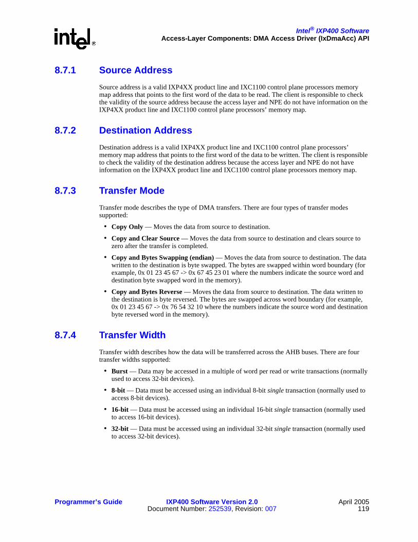
Intel® IXP400 SoftwareAccess-Layer Components: DMA Access Driver (IxDmaAcc) API
Programmer’s Guide IXP400 Software Version 2.0 April 2005Document Number: 252539, Revision: 007 119
8.7.1 Source AddressSource address is a valid IXP4XX product line and IXC1100 control plane processors memory map address that points to the first word of the data to be read. The client is responsible to check the validity of the source address because the access layer and NPE do not have information on the IXP4XX product line and IXC1100 control plane processors’ memory map.
8.7.2 Destination AddressDestination address is a valid IXP4XX product line and IXC1100 control plane processors’ memory map address that points to the first word of the data to be written. The client is responsible to check the validity of the destination address because the access layer and NPE do not have information on the IXP4XX product line and IXC1100 control plane processors memory map.
8.7.3 Transfer ModeTransfer mode describes the type of DMA transfers. There are four types of transfer modes supported:
• Copy Only — Moves the data from source to destination.
• Copy and Clear Source — Moves the data from source to destination and clears source to zero after the transfer is completed.
• Copy and Bytes Swapping (endian) — Moves the data from source to destination. The data written to the destination is byte swapped. The bytes are swapped within word boundary (for example, 0x 01 23 45 67 -> 0x 67 45 23 01 where the numbers indicate the source word and destination byte swapped word in the memory).
• Copy and Bytes Reverse — Moves the data from source to destination. The data written to the destination is byte reversed. The bytes are swapped across word boundary (for example, 0x 01 23 45 67 -> 0x 76 54 32 10 where the numbers indicate the source word and destination byte reversed word in the memory).
8.7.4 Transfer WidthTransfer width describes how the data will be transferred across the AHB buses. There are four transfer widths supported:
• Burst — Data may be accessed in a multiple of word per read or write transactions (normally used to access 32-bit devices).
• 8-bit — Data must be accessed using an individual 8-bit single transaction (normally used to access 8-bit devices).
• 16-bit — Data must be accessed using an individual 16-bit single transaction (normally used to access 16-bit devices).
• 32-bit — Data must be accessed using an individual 32-bit single transaction (normally used to access 32-bit devices).

Intel® IXP400 SoftwareAccess-Layer Components: DMA Access Driver (IxDmaAcc) API
April 2005 IXP400 Software Version 2.0 Programmer’s Guide120 Document Number: 252539, Revision: 007
8.7.5 Addressing ModesAddressing mode describes the types of source and destination addresses to be accessed. Two addressing modes are supported:
• Incremental Address — Address increments after each access, and is normally used to address a contiguous block of memory (i.e., SDRAM).
• Fixed Address — Address remains the same for all access, and is normally used to operate on FIFO-like devices (i.e., UART).
8.7.6 Transfer LengthThis is the size of the data to be transferred from the source address to the destination address. Transfer length restrictions are:
• Transfer length of 8-bit devices can be in multiple of byte, half-word, or word
• Transfer length of 16-bit devices can be in multiple of half-word or word
• Transfer length of 32-bit devices is in multiple of word
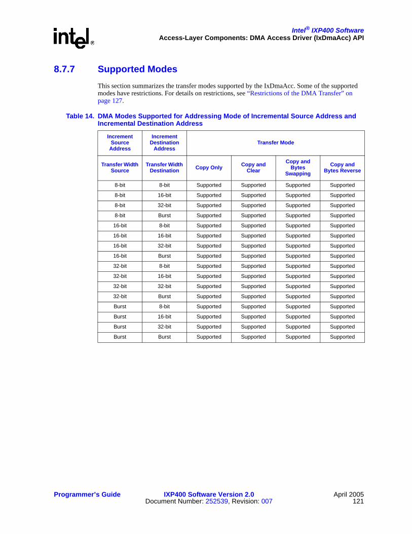
Intel® IXP400 SoftwareAccess-Layer Components: DMA Access Driver (IxDmaAcc) API
Programmer’s Guide IXP400 Software Version 2.0 April 2005Document Number: 252539, Revision: 007 121
8.7.7 Supported ModesThis section summarizes the transfer modes supported by the IxDmaAcc. Some of the supported modes have restrictions. For details on restrictions, see “Restrictions of the DMA Transfer” on page 127.
Table 14. DMA Modes Supported for Addressing Mode of Incremental Source Address andIncremental Destination Address
Increment Source
Address
Increment Destination
AddressTransfer Mode
Transfer Width Source
Transfer Width Destination Copy Only Copy and
ClearCopy and
Bytes Swapping
Copy and Bytes Reverse
8-bit 8-bit Supported Supported Supported Supported
8-bit 16-bit Supported Supported Supported Supported
8-bit 32-bit Supported Supported Supported Supported
8-bit Burst Supported Supported Supported Supported
16-bit 8-bit Supported Supported Supported Supported
16-bit 16-bit Supported Supported Supported Supported
16-bit 32-bit Supported Supported Supported Supported
16-bit Burst Supported Supported Supported Supported
32-bit 8-bit Supported Supported Supported Supported
32-bit 16-bit Supported Supported Supported Supported
32-bit 32-bit Supported Supported Supported Supported
32-bit Burst Supported Supported Supported Supported
Burst 8-bit Supported Supported Supported Supported
Burst 16-bit Supported Supported Supported Supported
Burst 32-bit Supported Supported Supported Supported
Burst Burst Supported Supported Supported Supported

Intel® IXP400 SoftwareAccess-Layer Components: DMA Access Driver (IxDmaAcc) API
April 2005 IXP400 Software Version 2.0 Programmer’s Guide122 Document Number: 252539, Revision: 007
Table 15. DMA Modes Supported for Addressing Mode of Incremental Source Address andFixed Destination Address
Increment Source
Address
Increment Destination
AddressTransfer Mode
Transfer Width Source
Transfer Width Destination Copy Only Copy and
ClearCopy and
Bytes Swapping
Copy and Bytes Reverse
8-bit 8-bit Supported Supported Supported Supported
8-bit 16-bit Supported Supported Supported Supported
8-bit 32-bit Supported Supported Supported Supported
8-bit Burst Not Supported Not Supported Not Supported Not Supported
16-bit 8-bit Supported Supported Supported Supported
16-bit 16-bit Supported Supported Supported Supported
16-bit 32-bit Supported Supported Supported Supported
16-bit Burst Not Supported Not Supported Not Supported Not Supported
32-bit 8-bit Supported Supported Supported Supported
32-bit 16-bit Supported Supported Supported Supported
32-bit 32-bit Supported Supported Supported Supported
32-bit Burst Not Supported Not Supported Not Supported Not Supported
Burst 8-bit Supported Supported Supported Supported
Burst 16-bit Supported Supported Supported Supported
Burst 32-bit Supported Supported Supported Supported
Burst Burst Not Supported Not Supported Not Supported Not Supported

Intel® IXP400 SoftwareAccess-Layer Components: DMA Access Driver (IxDmaAcc) API
Programmer’s Guide IXP400 Software Version 2.0 April 2005Document Number: 252539, Revision: 007 123
8.8 Data FlowThe purpose of the DMA access layer is to transfer DMA configuration information from its clients to the NPEs. It is a control component where the actual DMA data flow is transparent to the IxDmaAcc component.
8.9 Control FlowFor a DMA transaction to start, the client must initialize the DMA access layer, write to the queue manager, and receive a status of the transaction.
The IxDmaAcc component simultaneously supports multiple services. Consequently, a new request may be submitted before the confirmation of a previous DMA request is received from the NPE. The DMA Access layer API, however, assumes that all requests originate from the same Intel XScale core task. The DMA request is queued in the AQM’s request queue and waits to be serviced by the DMA NPE.
Table 16. DMA Modes Supported for Addressing Mode of Fixed Source Address andIncremental Destination Address
Increment Source
Address
Increment Destination
AddressTransfer Mode
Transfer Width Source
Transfer Width Destination Copy Only Copy and
ClearCopy and
Bytes Swapping
Copy and Bytes Reverse
8-bit 8-bit Supported Supported Supported Supported
8-bit 16-bit Supported Supported Supported Supported
8-bit 32-bit Supported Supported Supported Supported
8-bit Burst Supported Supported Supported Supported
16-bit 8-bit Supported Supported Supported Supported
16-bit 16-bit Supported Supported Supported Supported
16-bit 32-bit Supported Supported Supported Supported
16-bit Burst Supported Supported Supported Supported
32-bit 8-bit Supported Supported Supported Supported
32-bit 16-bit Supported Supported Supported Supported
32-bit 32-bit Supported Supported Supported Supported
32-bit Burst Supported Supported Supported Supported
Burst 8-bit Not Supported Not Supported Not Supported Not Supported
Burst 16-bit Not Supported Not Supported Not Supported Not Supported
Burst 32-bit Not Supported Not Supported Not Supported Not Supported
Burst Burst Not Supported Not Supported Not Supported Not Supported

Intel® IXP400 SoftwareAccess-Layer Components: DMA Access Driver (IxDmaAcc) API
April 2005 IXP400 Software Version 2.0 Programmer’s Guide124 Document Number: 252539, Revision: 007
Upon completion of the DMA transfer, the NPE writes a message to the AQM-done queue. The AQM dispatcher then calls the ixDmaAcc callback and the access layer calls the client callback.
Figure 45 shows the overall flow of the DMA transfer operation between the client, the access layer, and the NPE.
8.9.1 DMA InitializationFigure 46 and the following steps describe the DMA access-layer initialization:
Figure 45. IxDmaAcc Control Flow
IxDmaAccClient Task IxQMgr
NPE
1. ixDmaAccInit
2. ixDmaAccDmaTransfer
3. ixQMgrQWrite
4. IX_STATUS
7. ixDmaAccDoneCallback
8. Client Callback
6. WriteDoneFIFO
5. ReadReqFIFO
The NPE is triggered by a hardware event toread a DMA transfer request descriptor.A DMA transfer is performed and when thetransfer is completed the descriptor pointer ispassed on to the DMA Done Queue.The descriptor contains the client callbackfunction pointer that is called when thedescriptor is passed back to IxDmaAcc (Steps7 and 8)
B2359-03

Intel® IXP400 SoftwareAccess-Layer Components: DMA Access Driver (IxDmaAcc) API
Programmer’s Guide IXP400 Software Version 2.0 April 2005Document Number: 252539, Revision: 007 125
1. Client calls ixDmaAccInit to initialize the IxDmaAcc component with an NPE ID as a parameter. The NPE ID indicates which NPE is been used to provide the DMA functionality.
2. ixDmaAccInit checks if ixQmgr and the OSAL components have been initialized.
3. ixDmaAccInit calls ixDmaAccDescriptorPoolInit to allocate and initialize an array of descriptor data structures to store the DMA request and client’s callback function.(See the ixDmaAccDescriptorManager description.)
4. ixDmaAccInit calls ixQmgrConfig to configure the DMA request queue and the DMA done queue.The queue ID depends on which NPE the DMA component will be loaded. The selection of which NPE to run is made during run time by the client code.The client also need to initialize AQM (the Queue Manager).
5. ixDmaAccInit calls ixQMgrNotificationCallbackSet to register the callback function for the DMA-done queue.
6. ixDmaAccInit calls ixOsal to initialize mutex.The mutex ID will be used to access queue descriptor entry pool.ixDmaAccInit returns IX_DMA_SUCCESS upon completion of the DMA initialization.
8.9.2 DMA Configuration and Data TransferFigure 47 describes the configuration and DMA data transfer between a client and an NPE.
Figure 46. IxDMAcc Initialization
Client IxDmaAcc IxQMg
1. ixDmaAccInit
4. ixQMgrConfig
5. IxQMgrNotificationCallbackSet
IX_DMA_SUCCESS
IxDmaAccDescriptorManager
2. Init Config
IX_SUCCESS
ixOsal
6. ixOsalMutexInit
3. ixDmaAccDescriptorPoolInit
B2360-02

Intel® IXP400 SoftwareAccess-Layer Components: DMA Access Driver (IxDmaAcc) API
April 2005 IXP400 Software Version 2.0 Programmer’s Guide126 Document Number: 252539, Revision: 007
0. Client needs to initialize and configure the hardware for the DMA transfer to ensure that the devices are set up properly and ready for DMA transfer.
1. Client requests the DMA transfer by calling ixDmaAccDmaTransfer function.
2. Internally, ixDmaAccDmaTransfer function calls ixDmaAccValidateParams function to validate the client’s input parameters.
3. If the client input parameters are valid, the ixDmaAccDmaTransfer function gets a descriptor entry from the descriptor manager.The descriptor pool needs to be guarded by mutual exclusion because there are two contexts that access the pool descriptor buffer. The ixDmaAcc component will get the pool entry and the AQM will free the entry pool (via callback).
4. The ixDmaAccDmaTransfer function composes the descriptor — based on the client’s parameters — and calls ixQMgrQWrite to queue the descriptor to AQM.
5. ixDmaAccDmaTransfer returns and gets ready to process the new DMA transfer request.
6. The NPE reads the queue manager and does the DMA transfers. Upon completion of the DMA transfer, the NPE writes to AQM’s done queue. The AQM dispatcher calls the IxDmaAcc’s registered callback function.
7. IxDmaAccCallback calls ixQMgrQRead to read the result and that result is stored in the third descriptor. If the third word of the descriptor is zero, an AHB error is asserted by a peripheral having been accessed.
Figure 47. DMA Transfer Operation
Client IxDmaAcc IxQMgr
4. ixQMgrQWriteIX_DMA_SUCCESS
6. ixQMgrCallback
9. ClientCallback
NPE
7. ixQMgrQRead
IxDmaAccDesMgr*
IX_STATUS
IX_STATUS
HWAccixOsal
1. ixDmaAccDmaTransfer
2. ixDmaAccValidateParams
0. Init and config
3.1 ixOsalMutexLock
3.2 ixDmaAccDescriptorGet
3.3 ixOsalMutexUnlock
5.1 ReadRequestQueue5.2 WriteDoneQueue
8.1 ixOsalMutexLock
8.3 ixOsalMutexUnlock
8.2 ixDmaAccDescriptorFree
10. Release Resources
B2361-02

Intel® IXP400 SoftwareAccess-Layer Components: DMA Access Driver (IxDmaAcc) API
Programmer’s Guide IXP400 Software Version 2.0 April 2005Document Number: 252539, Revision: 007 127
8. The descriptor pool needs to be guarded by mutual exclusion because there are two contexts that access the pool descriptor buffer (see Step 3).
9. IxDmaAccCallback frees the descriptor.The descriptor pool needs to be guarded by mutual exclusion (see Step 3).
10. IxDmaAccCallback calls client registered callback.
11. Client releases the resources allocated in Step 0.
8.10 Restrictions of the DMA TransferThe client is responsible for ensuring that the following restrictions are followed when issuing a DMA request:
• The Intel XScale core is operating in the big-endian mode.
• The host devices are operating in big-endian mode. This means that the valid bytes for 8-bit and 16-bit transfer width are in the most-significant bytes (MSB). For example, for the 16-bit transfer, the data is 0xAABBXXXX, where X is don’t care value.
— There is a slight difference in the access to the APB memory map region, specifically for UART accessed. A read from an APB target is a 32-bit read from a word-aligned address.
— In the case of the UART Rx and Tx FIFOs, only the least significant byte (bits 7:0) of each word read/written contains valid data not in the MSB. Therefore, instead of using 0xC8000000 for UART1 and 0xC8001000 for UART2, any DMA request involving the UARTs must instead specify an address of 0xC8000003 for UART1 and 0xC8001003 for UART2 (in both cases the transfer width should be set to 8 bits). APB discards 1:0 bit address when decoding the AHB addresses. Therefore, valid data is read in MSB.
• Fixed address does not support burst mode. Fixed address associates with a single transaction. This means that the fixed address will either have a transfer width of 8-bit, 16-bit, or 32-bit single transaction. Fixed address (either fixed source address or fixed destination address) does not support burst transaction because burst transaction will always increment the address throughout the transaction. In addition, the AHB coprocessor does not have an instruction set to do burst transfer on fixed address mode.
• Fixed source address with copy and clear transfer mode, the source is clear only once after the transfer is completed.
• In the fixed source address mode, the client application is responsible to ensure that the data is available for transfer. For example, using FIFO with entry size 32-bit as a fixed address mode with the transfer length of 8 bytes, the client must ensure that the data is available before the DMA transfer is performed.
• Due to the asymmetric nature of the expansion bus, the incrementing source address and a “burst” transfer width will not support the “copy and clear” mode for expansion bus sources. The reason that this mode is not supported is that expansion bus targets can be read in burst mode, but they cannot be written in burst mode.
• If DMA transfer mode of “Byte-Swapped” or “Byte Reverse” is selected and if the Source DMA Addressing mode is “Incremental,” the DMA Source address must be “word-aligned” and the DMA transfer length would be a multiple of words. The reason is that endianness swapping will always be done on the word boundary.

Intel® IXP400 SoftwareAccess-Layer Components: DMA Access Driver (IxDmaAcc) API
April 2005 IXP400 Software Version 2.0 Programmer’s Guide128 Document Number: 252539, Revision: 007
• Burst mode is not supported for DMA targets at AHB South Bus. This is due to hardware restriction. Therefore, all DMA transactions originated or designated the south AHB bus peripherals is carried out in single transaction mode.
• The DMA access component is fully tested on SDRAM and flash devices only. Even though the IxDmaAcc is designed to provide capability to offload large data transfers between peripherals in the IXP4XX product line and IXC1100 control plane processors’ memory map.
• These DMA restrictions apply when a flash is a destination device:
— Burst mode is not supported and only supports single mode.
— Incremental source to fixed destination DMA addressing mode is not supported.
— DMA transfer width for the destination must match the flash device data bus width.
— Byte-reverse DMA mode with fixed source to incremental destination is not supported with the Flash write buffer mode.
• These DMA restrictions apply when a flash is a source device:
— Copy and clear DMA mode is not supported
— DMA transfer width for the source must match the Flash device data bus width.
8.11 Error HandlingIxDmaAcc returns an error type to the user when the client is expected to handle the error. Internal errors will be reported using standard IXP4XX product line and IXC1100 control plane processors error-reporting techniques, such as the OSAL layer’s error-reporting mechanism.
8.12 Little EndianThis component does not work in little-endian mode, nor will codelets that utilize this component.

Intel® IXP400 Software
Programmer’s Guide IXP400 Software Version 2.0 April 2005Document Number: 252539, Revision: 007 129
Access-Layer Components:Ethernet Access (IxEthAcc) API 9
This chapter describes the Intel® IXP400 Software v2.0’s “Ethernet Access API” access-layer component.
9.1 What’s NewThe following changes and enhancements were made to this component in software release 2.0:
• The Ethernet subsystem has been enhanced to include support for the Intel® IXP46X Product Line of Network Processors. This includes supporting the MII interface attached to NPE-A. All enumerations and definitions reference the Ethernet port on NPE-A as Port 2, except for the ixp_ne_dest_port and ixp_ne_src_port IX_OSAL_MBUF fields.
Note: The Intel® IXP46X product line processors include an option for a 4-port SMII capability, using four Ethernet coprocessors on NPE-B. In software release 2.0, this functionality is not supported. On NPE-B, only a single MII interface is supported.
• New API functions have been added for enhancing Ethernet diagnostic capabilities and forcing a hard immediate shutdown of ports in emergency security situations. These new functions are:— ixEthAccPortNpeLoopbackEnable(), ixEthAccPortNpeLoopbackDisable()— ixEthAccPortTxEnable(), ixEthAccPortTxDisable()— ixEthAccPortRxEnable(), ixEthAccPorRxDisable()— ixEthAccPortMacReset()
• New API ixEthAccMiiAccessTimeoutSet(). This new function is used to override the default timeout value (100ms) and retry count when reading or writing MII registers using ixEthAccMiiWriteRtn() or ixEthAccMiiReadRtn(). This is useful to speed up read/write operations to PHY registers. ixEthAccMiiWriteRtn() and ixEthAccMiiReadRtn() are unmodified, to retain backwards compatibility.
• The number of receive priority queues is now 8 for configurations where NPE microcode with QoS-enabled Ethernet services are configured for NPE-A.
9.2 IxEthAcc OverviewThe IxEthAcc component (along with its related components, IxEthDB and IxEthMii) provides data plane, control plane, and management plane information for the Ethernet MAC devices residing on the Intel® IXP4XX Product Line of Network Processors and IXC1100 Control Plane Processor. Depending on which processor variants are being used, the Intel® IXP4XX product line and IXC1100 control plane processors contain one, two, or three 10/100-Mbps Ethernet MAC devices.

Intel® IXP400 SoftwareAccess-Layer Components: Ethernet Access (IxEthAcc) API
April 2005 IXP400 Software Version 2.0 Programmer’s Guide130 Document Number: 252539, Revision: 007
The data path for each of these devices is accessible via dedicated NPEs. One Ethernet MAC is provided on each NPE. The NPEs are connected to the North AHB for access to the SDRAM where frames are stored. The control access to the MAC registers is via the APB Bridge, which is memory-mapped to the Intel XScale core.
The IxEthAcc component is strictly limited to supporting the internal Ethernet MACs on the IXP4XX product line and IXC1100 control plane processors.
The services provided by the Ethernet Access component include:
• Ethernet Frame Transmission
• Ethernet Frame Reception
• Ethernet MAC Statistics, Tracking and Reporting
• Ethernet Usage of the IxEthDB Filtering/Learning Database
PHY control is accomplished via the MII interface, which is accessible via the MAC control registers. This PHY control is not performed by the IxEthAcc component, but rather by the IxEthMii component. Although mechanisms to set the port operation state have been provided in the IxEthAcc module, true operating state-link indications should be obtained from IxEthMii.
9.3 Ethernet Access Layers: Architectural OverviewIxEthAcc is not a stand-alone API. It relies on services provided by a number of other components. The NPE microcode, IxEthDB API and messaging services support IxEthAcc’s primary role of managing the scheduling, transmission and reception of Ethernet traffic.
9.3.1 Role of the Ethernet NPE MicrocodeThe Ethernet NPE microcode is responsible for moving data between an Ethernet MAC and external data memory where it can be made available to the Intel XScale core. In addition, the Ethernet NPE microcode performs a number of data-processing operations.
There are many possible functions that can be performed by the NPE microcode, some examples of which are described here. On the Ethernet receive path, the Ethernet NPE microcode performs filtering (according to the destination MAC address), conversion of frame header data to support VLAN/QoS or other features, detects specific characteristics about a frame and notifies the client via IX_OSAL_MBUF header flags, and collects MAC statistics. On the Ethernet transmit path, the Ethernet NPE microcode can convert the frame header in support of VLAN/QoS or other features, perform priority queuing of outgoing frames, and collect MAC statistics collection.
It is important to note that the Ethernet NPE microcode support for Ethernet data transport does not extend to support all Ethernet-related protocols and functions. For example, the NPE microcode does not automatically detect that a frame is part of an SMB protocol message and prioritize it automatically above incoming HTTP response data. However, the lack of NPE-level support for these features in no way inhibits the Intel XScale core-based software from implementing them.
Communication between an Ethernet NPE and the Intel XScale core is facilitated by two mechanisms. The IxQMgr component is used to handle the data path communications between the Intel XScale core-based code and NPEs, and is described below. IxNpeMh is used to facilitate the communication of control-type messages between IxEthAcc and the NPEs.

Intel® IXP400 SoftwareAccess-Layer Components: Ethernet Access (IxEthAcc) API
Programmer’s Guide IXP400 Software Version 2.0 April 2005Document Number: 252539, Revision: 007 131
9.3.2 Queue ManagerThe AHB Queue Manager is a hardware block that communicates buffer pointers between the NPE cores and the Intel XScale core. The IxQMgr API provides the queuing services to the access-layer and other upper level software executing on the Intel XScale core. The primary use of these interfaces is to communicate the existence and location of network payload data and Ethernet service configuration information in external SDRAM.
Ethernet frames are presented to an Ethernet-capable NPE via its Ethernet coprocessor, which serves as an interface between the Ethernet MAC and the NPE core block. Ethernet frame payloads are transferred from the Ethernet coprocessor to the host NPE in discrete blocks of data. The frames are buffered in NPE internal data memory, optionally filtered according to their destination MAC address, checked for errors, and then (assuming that no errors exist and that the frame is not filtered) transferred to external SDRAM. The Intel XScale core client (via IxEthAcc) is notified of the arrival of new frames via the queue manager interface.
9.3.3 Learning/Filtering DatabaseIxEthAcc relies on the IxEthDB component for the MAC learning and filtering required in a routing or bridging application.
The NPEs provide a function whereby MAC address-source learning is performed on received (ingress) Ethernet frames. Not all NPE microcode images provide the filtering capability. If source learning is enabled, the source MAC addresses are automatically populated in a learning database. For a frame to be filtered, there must be a filtering database entry whose MAC address matches the frame’s destination MAC address and whose port ID matches that of the ingress MAC.
Each entry in the filtering database is composed of a MAC address and a logical port number. Whenever the bridge receives a frame, the frame is parsed to determine the destination MAC address, and the filtering database is consulted to determine the port to which the frame should be forwarded. If the destination MAC address of the frame being processed has been learned on the same interface from which it was received, it is dropped. Otherwise, the frame is forwarded from the NPE to the Intel XScale core.
9.3.4 MAC/PHY ConfigurationIxEthMii is used primarily to manipulate a minimum number of necessary configuration registers on Ethernet PHYs supported on the Intel® IXDP425 / IXCDP1100 Development Platform, the Coyote* Gateway Reference Design, and the Intel® IXDP465 Development Platform, without the support of a third-party operating system. Codelets and software used for Intel internal validation are the consumers of this API, although it is provided as part of the IXP400 software for public use.
While the MAC configuration is performed within IxEthAcc, the PHY configuration requires both IxEthAcc and IxEthMii. Since the MAC also controls the MDIO interface that is used for configuring the PHY, IxEthMii must initialize the MAC in order for the PHY to be configured. IxEthAcc initializes the MAC and virtual memory mapping and executes all register reads/writes on the PHY. IxEthMii provides the register definitions for supported PHYs. Thus, IxEthMii and IxEthAcc are dependant upon each other.

Intel® IXP400 SoftwareAccess-Layer Components: Ethernet Access (IxEthAcc) API
April 2005 IXP400 Software Version 2.0 Programmer’s Guide132 Document Number: 252539, Revision: 007
9.4 Ethernet Access Layers: Component FeaturesThe Ethernet access component features may be divided into three areas:
• Data Path — Responsible for the transmission and reception of IEEE 803.2 Ethernet frames. The Data Path is performed by IxEthAcc.
• Control Path — Responsible for the control of the MAC interface characteristics and some learning/filtering database functions. Control Plane functionality is included in both IxEthAcc and IxEthDB
• Management Information — Responsible for retrieving counter and statistical information associated with the interfaces. IxEthAcc provides this management support.

Intel® IXP400 SoftwareAccess-Layer Components: Ethernet Access (IxEthAcc) API
Programmer’s Guide IXP400 Software Version 2.0 April 2005Document Number: 252539, Revision: 007 133
9.5 Data PlaneThe data plane is responsible for the transmission and reception of Ethernet frames.
Figure 48. Ethernet Access Layers Block Diagram
MAC
Filt
erin
g/VL
AN
/Fire
wal
l, et
c...
Dat
abas
e M
anag
emen
t(Ix
EthD
b)
Intel XScale®
Core
Media Assist
AHBQueue
Manager
IxQMgr
Physical
IxEthAcc Component
Statistics
Buffer Management
Data PathTx/Rx
IxNpeMh
IxOSAL
EthernetPHY
NPEs
10/100BtMAC
NPE Core MessageBus
ControlRegisters
`
PHY
Man
agem
ent
(IxEt
hMii)
System Config
Data Path
B2362-04
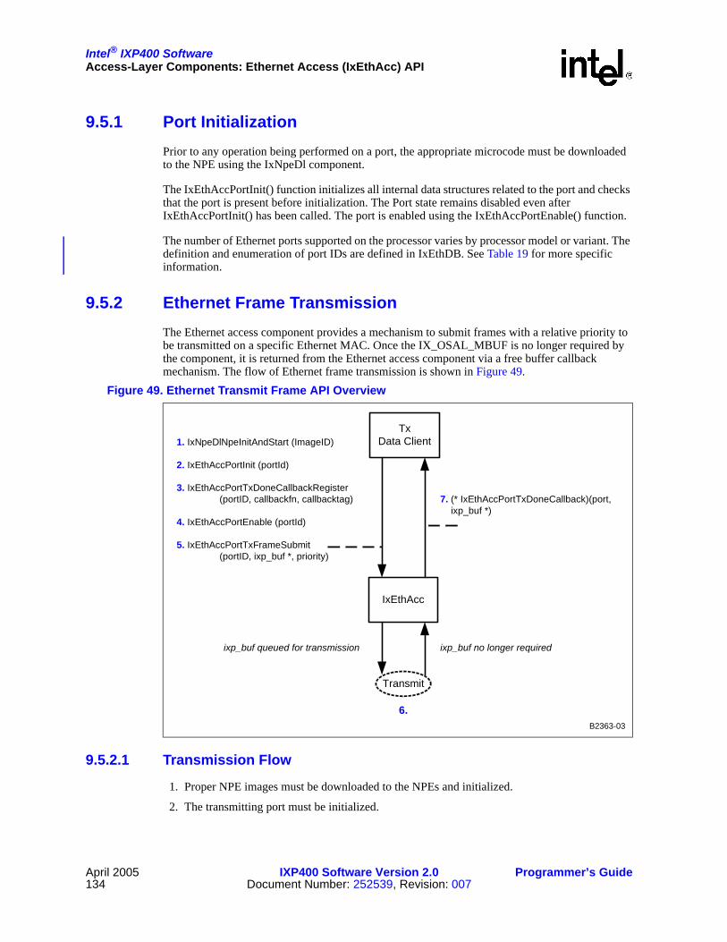
Intel® IXP400 SoftwareAccess-Layer Components: Ethernet Access (IxEthAcc) API
April 2005 IXP400 Software Version 2.0 Programmer’s Guide134 Document Number: 252539, Revision: 007
9.5.1 Port InitializationPrior to any operation being performed on a port, the appropriate microcode must be downloaded to the NPE using the IxNpeDl component.
The IxEthAccPortInit() function initializes all internal data structures related to the port and checks that the port is present before initialization. The Port state remains disabled even after IxEthAccPortInit() has been called. The port is enabled using the IxEthAccPortEnable() function.
The number of Ethernet ports supported on the processor varies by processor model or variant. The definition and enumeration of port IDs are defined in IxEthDB. See Table 19 for more specific information.
9.5.2 Ethernet Frame TransmissionThe Ethernet access component provides a mechanism to submit frames with a relative priority to be transmitted on a specific Ethernet MAC. Once the IX_OSAL_MBUF is no longer required by the component, it is returned from the Ethernet access component via a free buffer callback mechanism. The flow of Ethernet frame transmission is shown in Figure 49.
9.5.2.1 Transmission Flow
1. Proper NPE images must be downloaded to the NPEs and initialized.
2. The transmitting port must be initialized.
Figure 49. Ethernet Transmit Frame API Overview
TxData Client1. IxNpeDlNpeInitAndStart (ImageID)
2. IxEthAccPortInit (portId)
3. IxEthAccPortTxDoneCallbackRegister(portID, callbackfn, callbacktag)
4. IxEthAccPortEnable (portId)
5. IxEthAccPortTxFrameSubmit(portID, ixp_buf *, priority)
ixp_buf queued for transmission
IxEthAcc
Transmit
7. (* IxEthAccPortTxDoneCallback)(port, ixp_buf *)
ixp_buf no longer required
6.B2363-03

Intel® IXP400 SoftwareAccess-Layer Components: Ethernet Access (IxEthAcc) API
Programmer’s Guide IXP400 Software Version 2.0 April 2005Document Number: 252539, Revision: 007 135
3. Register a callback function for the port. This function will be called when the transmission buffer is placed in the TxDone queue.
4. After configuring the port, the transmitting port must be enabled in order for traffic to flow.
5. Submit the frame, setting the appropriate priority. This places the IX_OSAL_MBUF on the transmit queue for that port.
6. IxEthAcc transmits the frame on the wire. When transmission is complete, the IX_OSAL_MBUF is placed in the TxDone queue.
7. Frame transmission is complete when the TxDone callback function is invoked. The callback function is passed a pointer to that IX_OSAL_MBUF.
The frame-transmission API is asynchronous in nature. Because the transmit frame request queues the frame for transmission at a later point, the call is non-blocking. There is no direct status indication as to whether the frame was successfully transmitted on the wire or not. Statistics, however, are maintained at the MAC level for failed transmit attempts.
9.5.2.2 Transmit Buffer Management and Priority
The overall queuing topology for the Ethernet transmission system is made up of the following queues:
• Software queues within IxEthAcc for buffering traffic when downstream queues are full, or for establishing priority queuing.
• IxQMgr queues for passing data to and from the NPEs. A maximum of 128 entries per port are supported for the TxEnet queues, and there is a single 128 entry queue for TxEnetDone.
• NPE microcode queues, used to hold IX_OSAL_MBUF header data for transmission. There are 64 entries in the NPE microcode queue(s).
Figure 50 provides a visual explanation of queue management for Ethernet transmission.
The IxQMgr queues are a maximum of 128 entries deep per port. The frame submit function must internally queue (in the IxEthAcc software) frames which are submitted in excess of a predefined limit. All internally queued buffers submitted for transmission but not queued to the hardware queues are stored in IxEthAcc software queues. If priority FIFO queuing is being used, the frames will be saved in individual per priority FIFOs.
Frames will be submitted to the port specific IxQMgr queue when a low/empty threshold is reached on the queue. From there, the buffer header is passed into the NPE queue that supports that respective port. If priority queueing is enabled, the NPE can re-order the frames internally to ensure that higher priority frames are transmitted before lower priority frames.
Once frame transmission has completed, the buffer is placed on the TxEnetDone IxQMgr queue. This queue contains multiplexed entries from both NPE ports. The IxEthAcc software consumes entries from this queue and returns the buffers to the client via the function previously registered by IxEthAccTxDoneCallbackRegister( ).
There is no specific port flush capability. To retrieve submitted buffers from the system, the port must be disabled, using the IxEthAccPortDisable() function. This has the result of returning all Tx buffers to the TxDone queue and then passed to the user via the registered TxDone callback.

Intel® IXP400 SoftwareAccess-Layer Components: Ethernet Access (IxEthAcc) API
April 2005 IXP400 Software Version 2.0 Programmer’s Guide136 Document Number: 252539, Revision: 007
There are two scheduling disciplines selectable via the IxEthAccTxSchedulerDiscipline (). The frame submit behavior will be different for each case. Available scheduling disciplines are No Priority and Priority.
Figure 50. Ethernet Transmit Frame Data Buffer Flow
TxEn
et0
TxEn
et1
TxE
netD
one
Codelet or client application
IxEthAcc
IxQMgr
1. Initializations , Port Enables, Callback Registration...
2. Frame Submit (Port 0) Frame Submit (Port 1) Frame Submit (Port 2)
4. Load Tx Queues when low threshold reached
6. ixp_buf moved to TxDone queue
7. Demux free buffer to port specific callback
8. TxDoneCallback (Port 0) TxDoneCallback (Port 1) TxDoneCallback (Port 2)
3a. Route Tx buffers to 8 priority queues
B2364-04
FIFO_PRIORITY
3b. Load Tx Queues directly
FIFO_NO_PRIORITY
5. Move to NPE queue, then physical transmission
NPE C
Sw q
ueue
for
defe
rred
subm
issio
n
NPE B
TxE
net2
NPE A

Intel® IXP400 SoftwareAccess-Layer Components: Ethernet Access (IxEthAcc) API
Programmer’s Guide IXP400 Software Version 2.0 April 2005Document Number: 252539, Revision: 007 137
Tx FIFO No Priority
If the selected discipline is FIFO_NO_PRIORITY, then all frames may be directly submitted to the IxQMgr queue for that port if there is room on the port. Frames that cannot be queued in the IxQMgr queue are stored in an IxEthAcc software queue for deferred submission to the IxQMgr queue. The IxQMgr threshold in the configuration can be quite high. This allows the IxEthAcc software to burst frames into the IxQMgr queue and improve system performance due to the resultant higher cache hit rates.
Tx FIFO Priority
If the selected discipline is FIFO_PRIORITY, then frames are queued by IxEthAcc software in separate priority queues. The threshold in the IxQMgr must be kept quite low to improve fairness among packets submitted. Once the low threshold on the IxQMgr queue is reached, frames are selected from the priority queues in strict priority order (i.e., all frames are consumed from the highest priority queue before frames are consumed from the next lowest priority).
The priority is controlled by the IxEthAccTxPriority value in the IxEthAccPortTxFrameSubmit () function. IX_ETH_ACC_TX_PRIORITY_0 is the lowest priority submission and IX_ETH_ACC_TX_PRIORITY_7 is the highest priority submission.
There are no fairness mechanisms applied across different priorities. Higher priority frames could starve lower-priority frames indefinitely.
9.5.2.3 Using Chained IX_OSAL_MBUFs for Transmission / Buffer Sizing
Submission of chained IX_OSAL_MBUF clusters for transmission is supported, but excessive chaining may have an adverse impact on performance. It is expected that chained buffers are used to add protocol headers and for large packet handling. The payload portion of large PDUs may also use chained IX_OSAL_MBUF clusters. The suggested minimum size for the buffers within the payload portion of a packet is 64 bytes. The “transmit done” callback function is called with the head of the cluster IX_OSAL_MBUF only when the entire chain has completed transmission.
The minimum size for the buffer payload is 64 bytes, including the Ethernet FCS. The ixEthAccPortTxFrameAppendPaddingEnable () function will append up to 60 bytes to an undersized frame, and will also enable FCS calculation and appending.
9.5.3 Ethernet Frame ReceptionThe Ethernet access component provides a mechanism to register a callback to receive Ethernet frames from a particular MAC. The user-level callback is called for each Ethernet frame received. The Ethernet access component must be supplied with receive buffers prior to any receive activity on the Ethernet MAC. The flow of Ethernet frame reception is shown in Figure 51.
IxEthAcc also provides a callback mechanism that supports returning multiple frames to the user at the same time. This callback mechanism will return all available entries in all of the EthRx queues. Some operating systems may perform better when the stack is not invoked for each frame (for example, trigger a context switch for each frame). There is also a corresponding Multi-Buffer Callback registration function.

Intel® IXP400 SoftwareAccess-Layer Components: Ethernet Access (IxEthAcc) API
April 2005 IXP400 Software Version 2.0 Programmer’s Guide138 Document Number: 252539, Revision: 007
9.5.3.1 Receive Flow
1. Proper NPE images must be downloaded to the NPEs and initialized.
2. The receiving port must be initialized.
3. Register a callback function for the port. This function will be called each time a frame is received.
4. Preload free receive buffers for use by IxEthAcc.
5. After configuring the receiving port and pre-loading buffers, the receiving port is enabled, allowing traffic to be received.
6. An Ethernet frame is received on the wire and placed in the IxQMgr Rx queue.
7. The callback function is called for each frame, being passed a pointer to that IX_OSAL_MBUF. The callback function can now process and/or de-multiplex the incoming frame(s).
8. The upper-level user or OS processes must recover the receive buffers once processing of the frame is completed, and replenish the RxFree queue using IxEthAccPortRxFreeReplenish() as needed.
Note: The process for multi-buffer receive callback is similar to what is described above, with the exception that the multi-buffer callback should not be invoked for every frame. A polling dispatch mechanism should be used.
Figure 51. Ethernet Receive Frame API Overview
1. IxNpeDlNpeInitAndStart (ImageID)
2. IxEthAccPortInit (portId)
3. IxEthAccPortRxDoneCallbackRegister (portID, callbackfn, callbacktag)
4. IxEthAccPortRxFreeReplenish (portID, ixp_buf *)
5. IxEthAccPortEnable (portId)
ixp_buf made available to Rx frame
IxEthAcc
Receive
8. free ixp_buf
7. (* IxEthAccPortRxCallback)(callbacktag, ixp_buf *, portID)
Ethernet frame received
6.
RxData Client
B2365-02
Intel® IXP400 SoftwareAccess-Layer Components: Ethernet Access (IxEthAcc) API
Programmer’s Guide IXP400 Software Version 2.0 April 2005Document Number: 252539, Revision: 007 139
9.5.3.2 Receive Buffer Management and Priority
The key interface from the NPEs to the receive data path (IxEthAcc) is a selection of queues residing in the queue manager hardware component. These queues are shown in Figure 52.
Buffer Sizing
The receive data plane subcomponent must provide receive buffers to the NPEs. These IX_OSAL_MBUFs should be sized appropriately to ensure optimal performance of the Ethernet receive subsystem. The IX_OSAL_MBUF should contain IX_ETHACC_RX_MBUF_MIN_SIZE bytes in a single data cluster, though chained IX_OSAL_MBUFs are also supported. It is expected that chained IX_OSAL_MBUFs will be used to handle large frames. Receive frames may be pushed into a chained IX_OSAL_MBUF structure, but excessive chaining will have an adverse impact upon performance.
The NPEs write data in 64 byte words. For maximum performance, the IX_OSAL_MBUF size should be greater than the maximum frame size (Ethernet header, payload and FCS), rounded up to the next 64 byte multiple. Supplying smaller IX_OSAL_MBUFs to the service results in IX_OSAL_MBUF chaining and degraded performances.
The minimum buffer size for IEEE 802.3 Ethernet frame traffic without VLAN or IPSEC features should be 1536 bytes (1518 byte Ethernet frame + 18 bytes for 64 byte alignment). For IEEE 802.3 traffic, the recommended size is 2,048 bytes. This is adequate to support VLAN-tagged Ethernet 802.3 frames, IPSec encapsulated Ethernet frames, “baby jumbo” frames without chaining, and “jumbo” frames with chaining. The maximum 802.11 frame size is 2348 bytes. Therefore, if the 802.3 <-> 802.11 Frame Conversion feature will be used, the IX_OSAL_MBUF should be sized at 2368 bytes (2348 + 20 for 64 byte alignment) or larger.
Buffers may not be filled up to their length. The NPE microcode will fill the IX_OSAL_MBUF fields up to the 64-byte boundary. The user should to be aware that the length of the received IX_OSAL_MBUFs may be smaller than the length of the supplied IX_OSAL_MBUFs.
Supplying Buffers
There are three separate free buffer IxQMgr queues allocated to providing the NPEs with receive buffers (one per port). The buffers are supplied on a per port basis via the user level interface ixEthAccPortRxFreeReplenish() function. The replenish function loads the port specific free buffer IxQMgr queue with an IX_OSAL_MBUF pointer. The replenish function can provide checking to ensure that the IX_OSAL_MBUF is at least as large as IX_ETHACC_RX_IXP_BUF_MIN_SIZE. If the port specific free buffer IxQMgr queue is full, the replenish function queues the buffer in a software queue. Once a low threshold on the specific queue is reached the software reloads the port specific free buffer queue from its software queue if available. Frames greater in size than the size of the IX_OSAL_MBUF provided by the replenish function will trigger chaining.
Note: The ixEthAccPortRxFreeReplenish() function can receive chained IX_OSAL_MBUFs, which the NPEs will be able to unchain as needed. This method may offer a performance improvement for some usage scenarios.
The user also must ensure that there are sufficient buffers assigned to this component to maintain wire-speed, Ethernet-receive performance. If the receive NPE does not have a receive buffer in advance of receiving an Ethernet frame, the frame will be dropped. Should a frame arrive while there are no free buffers is available, no callback indication will be provided and a rx_buffer_underrun counter will be incremented.
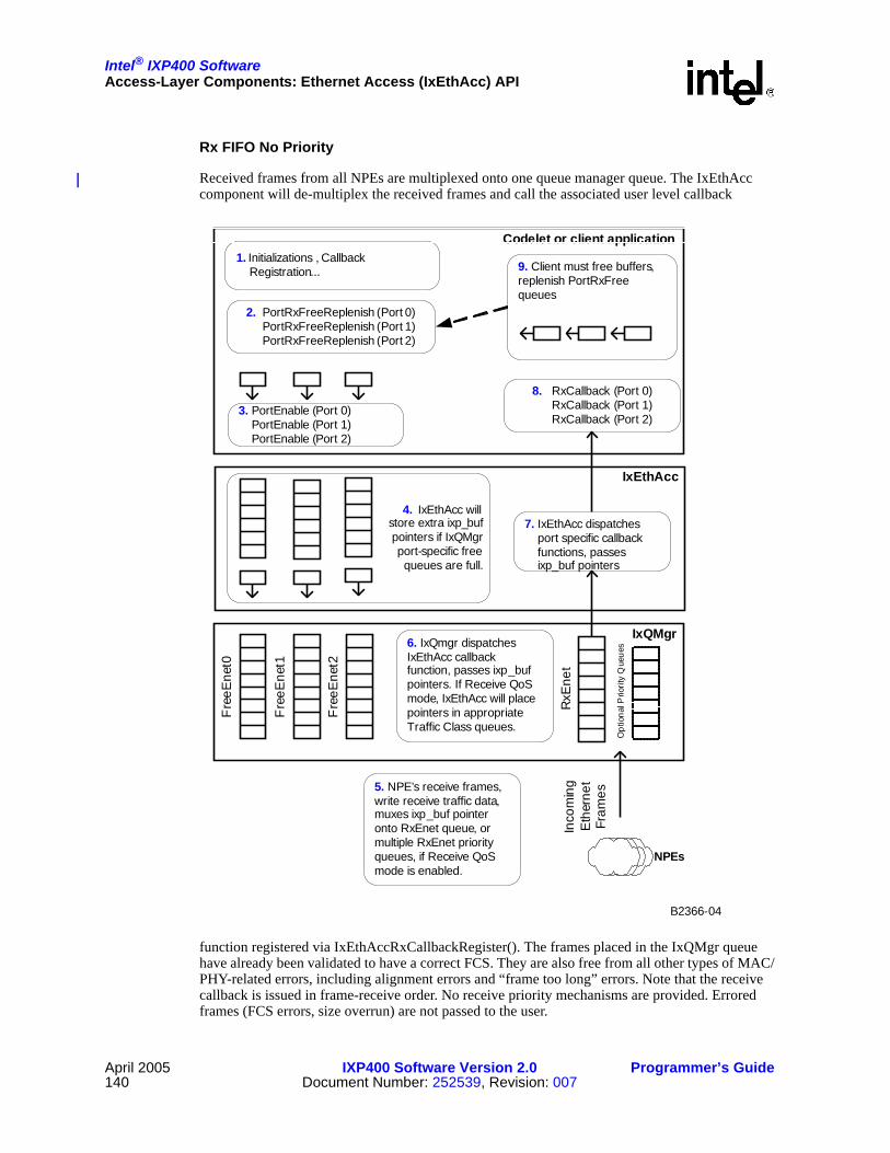
Intel® IXP400 SoftwareAccess-Layer Components: Ethernet Access (IxEthAcc) API
April 2005 IXP400 Software Version 2.0 Programmer’s Guide140 Document Number: 252539, Revision: 007
Codelet or client application
IxEthAcc
IxQMgr
1. Initializations , Callback Registration...
2. PortRxFreeReplenish (Port 0) PortRxFreeReplenish (Port 1) PortRxFreeReplenish (Port 2)
4. IxEthAcc will store extra ixp_bufpointers if IxQMgrport-specific freequeues are full.
6. IxQmgr dispatches IxEthAcc callback function, passes ixp_buf pointers. If Receive QoS mode, IxEthAcc will place pointers in appropriate Traffic Class queues.
8. RxCallback (Port 0) RxCallback (Port 1) RxCallback (Port 2)
Fre
eEne
t0
Fre
eEne
t1
3. PortEnable (Port 0) PortEnable (Port 1) PortEnable (Port 2)
9. Client must free buffers, replenish PortRxFree queues
RxE
net
Inco
min
g E
ther
net
Fram
es
7. IxEthAcc dispatches port specific callback functions, passes ixp_buf pointers
B2366-04
5. NPE’s receive frames, write receive traffic data, muxes ixp_buf pointer onto RxEnet queue, or multiple RxEnet priority queues, if Receive QoS mode is enabled.
Fre
eEne
t2
Opt
iona
l Prio
rity
Que
ues
NPEs
Rx FIFO No Priority
Received frames from all NPEs are multiplexed onto one queue manager queue. The IxEthAcc component will de-multiplex the received frames and call the associated user level callback
function registered via IxEthAccRxCallbackRegister(). The frames placed in the IxQMgr queue have already been validated to have a correct FCS. They are also free from all other types of MAC/PHY-related errors, including alignment errors and “frame too long” errors. Note that the receive callback is issued in frame-receive order. No receive priority mechanisms are provided. Errored frames (FCS errors, size overrun) are not passed to the user.

Intel® IXP400 SoftwareAccess-Layer Components: Ethernet Access (IxEthAcc) API
Programmer’s Guide IXP400 Software Version 2.0 April 2005Document Number: 252539, Revision: 007 141
This is configured using the ixEthAccRxSchedulingDisciplineSet() function.
Rx FIFO Priority (QoS Mode)
IxEthAcc can support the ability to prioritize frames based upon 802.1Q VLAN data on the receive path. This feature requires a compatible NPE microcode image with VLAN/QoS support. Enabling this support requires a two-part process: IxEthDB must be properly configured with support for this feature, and the Rx port in IxEthAcc must be configured using the ixEthAccRxSchedulingDisciplineSet() function.
In receive QoS mode, IxEthAcc will support up to four IxQMgr priority receive queues in configurations which involving only NPE-B and/or NPE-C. If NPE-A is configured for Ethernet by selecting an Ethernet-enabled NPE microcode image for NPE-A, then eight IxQMgr receive queues may be used. The NPE microcode will detect 802.1Q VLAN Priority data within an incoming frame or insert this data into a frame if configured to do so by IxEthDB. The NPE will then map the priority data to one of up to 8 traffic classes and places the IX_OSAL_MBUF header for each frame into its respective IxQMgr queue. IxEthAcc will service all frames in higher priority queues prior to servicing any entries in queues of a lower priority. Lower priority queues could be starved indefinitely.
The actual impact on system performance of the Rx FIFO priority mode is heavily influenced by the amount of traffic, priority level of the traffic, how often IxQMgr queues are serviced, and how many IxQMgr queues have entries during the time of servicing by the dispatcher loop.
If the IxEthAccPortMultiBufferRxCallback() function is used, it will return all currently available entries from all EthRx queues. If there are two entries in the Priority 3 EthRx queue and two entries in the Priority 1 EthRx queue, then four entries will be returned with the multi-buffer callback.
Enabling the Rx QoS Mode generally involves the following process: initialize IxEthDB, enable VLAN/QoS on the desired ports, download the appropriate QoS->Traffic Class priority map (or use the default one, which is 802.1P compliant), initialize IxEthAcc and set the Rx discipline.
Freeing Buffers
Once this service calls the callback with the receive IX_OSAL_MBUF, “ownership” of the buffer is transferred to the user of the access component (i.e., the access component will not free the buffer). Once IxEthAcc calls the registered user-level receive callback, the receive IX_OSAL_MBUF “ownership” is transferred to the user of the access component. IxEthAcc will not free the buffer. Should a chain of IX_OSAL_MBUFs be received, the head of the buffer chain is passed to the Rx callback.
Buffers can also be freed by disabling the port, using the IxEthAccPortDisable() function. This has the result of returning all Rx buffers to the Rx registered callback, which may then de-allocate the IX_OSAL_MBUFs to free memory.
Recycling Buffers
Buffers received (chained or unchained) on the Rx path can be used without modification in the Tx path. Rx and TxEnetDone buffers (chained or unchained) should have the length of each cluster reset to the cluster original size before re-using it in the ixEthAccPortRxFreeReplenish() function.

Intel® IXP400 SoftwareAccess-Layer Components: Ethernet Access (IxEthAcc) API
April 2005 IXP400 Software Version 2.0 Programmer’s Guide142 Document Number: 252539, Revision: 007
9.5.3.3 Additional Receive Path Information
No Receive Polling
An Rx polling interface is not provided for the service. This can easily be extended via queuing the received frames by the access component user and subsequently providing a polling interface.
Figure 52. Ethernet Receive Plane Data Buffer Flow
Codelet or client application
IxEthAcc
IxQMgr
1. Initializations , Callback Registration...
2. PortRxFreeReplenish (Port 0) PortRxFreeReplenish (Port 1) PortRxFreeReplenish (Port 2)
4. IxEthAcc will store extra ixp_bufpointers if IxQMgrport-specific freequeues are full.
6. IxQMgr dispatches IxEthAcc callback function, passes ixp_buf pointers. If Receive QoS mode, IxEthAcc will place pointers in appropriate Traffic Class queues.
8. RxCallback (Port 0) RxCallback (Port 1) RxCallback (Port 2)
Fre
eEne
t0
Fre
eEne
t1
3. PortEnable (Port 0) PortEnable (Port 1) PortEnable (Port 2)
9. Client must free buffers, replenish PortRxFree queues
RxE
net
Inco
min
g E
ther
net
Fram
es
7. IxEthAcc dispatches port specific callback functions, passes ixp_buf pointers
B2366-04
5. NPEs receive frames, write receive traffic data, muxes ixp_buf pointer onto RxEnet queue, or multiple RxEnet priority queues, if Receive QoS mode is enabled.
Fre
eEne
t2
Opt
iona
l Prio
rity
Que
ues
NPEs

Intel® IXP400 SoftwareAccess-Layer Components: Ethernet Access (IxEthAcc) API
Programmer’s Guide IXP400 Software Version 2.0 April 2005Document Number: 252539, Revision: 007 143
IPv4 Payload Detection
For every received frame delivered to the Intel XScale core, the NPE microcode reports whether the payload of the frame is an IPv4 packet by setting the ixp_ne_flags.ip_prot flag bit in the buffer header (as described in Table 22 on page 152). The NPE microcode examines the Length/Type field to determine whether the payload is IP. A value of 0x0800 indicates that the payload is IP.
The IPv4 payload detection service is enabled in all Ethernet-capable NPE microcode images. An NPE microcode version that is not VLAN-capable will always report VLAN-tagged frames as non-IP.
9.5.4 Data-Plane EndiannessAll data structures provided to the IxEthAcc components, such as IX_OSAL_MBUF headers or statistic structures, are defined by the target system byte order. No changes to data structures are required in order to use the access component data path interfaces as IxEthAcc effects any conversion required to communicate to the NPEs. The data pointed to by the IX_OSAL_MBUF (the IX_OSAL_MBUF payload) is expected to be in network byte order (big endian). No byte swapping takes place on the data prior to transmission to the Ethernet MAC.
9.5.5 Maximum Ethernet Frame SizeThe maximum supported Ethernet frame size is 16,320 bytes. This value is set on a per-port basis using the IxEthDB API.
9.6 Control PathThe main control path functions are performed by two external components: IxEthMii and IxEthDB.
IxEthMii is used primarily to manipulate a minimum number of necessary configuration registers on Ethernet PHYs supported on the IXDP425 / IXCDP1100 platform and IXDP465 platform without the support of a third-party operating system. IxEthMii exists as a separate function in order to make IxEthAcc independent of the specific PHY devices used in a system. However, IxEthAcc does retain control of configuring the Ethernet MAC devices on the NPEs and drives the MII and MDIO interfaces, which are used by IxEthMii to communicate physically with the PHYs.
IxEthDB is the learning and filtering database that runs within the context of the Intel XScale core. The IxEthDB component handles the database structure, maintenance, searching, and aging, and has an API for the provisioning of dynamic and static addresses. This database populates filtering entries on the NPEs and also retrieves learning entries from the NPEs. An API is provided to the access layer.

Intel® IXP400 SoftwareAccess-Layer Components: Ethernet Access (IxEthAcc) API
April 2005 IXP400 Software Version 2.0 Programmer’s Guide144 Document Number: 252539, Revision: 007
The relationship between IxEthAcc, IxEthDB, and IxEthMii is shown in Figure 53.
The control path component remaining for IxEthAcc is the provision of the MAC registers with their required functionality.
Figure 53. IxEthAcc and Secondary Components
IXP4XX
IxQMgr
AHB Queue
Manager
IxEthAcc IxEthMii (PHYconfiguration)
IxNpeMh
Linux Eth driver (ixp425_eth.c)
VxWorks END driver
(IxEthAccEnd.c)
PHY (e.g. LXT972 chip on IXDP425)
Linux* Ethernet stack
VxWorks* Ethernet stack
Data Plane
Control Plane
Codelets and test code
IxEthDB Access Layer
NPE
Ethernet coprocessor
NPE core
MAC Control Registers, MII
interface
B2369-02
Intel® IXP400 SoftwareAccess-Layer Components: Ethernet Access (IxEthAcc) API
Programmer’s Guide IXP400 Software Version 2.0 April 2005Document Number: 252539, Revision: 007 145
9.6.1 Ethernet MAC ControlThe role and responsibility of this module is to enable clients to configure the Ethernet coprocessor MACs for both NPEs. This API permits the setting and retrieval of uni-cast and multi-cast addresses, duplex mode configuration, FCS appending, frame padding, promiscuous mode configuration, and reading or writing from the MII interface.
9.6.1.1 MAC Duplex Settings
Functions are provided for setting the MACs at full or half duplex. This setting should match the setting of the connected PHYs.
9.6.1.2 MII I/O
IxEthAcc provides four functions that interact with the MII interfaces for the PHYs connected to the NPEs on the IXDP425 / IXCDP1100 platform and IXDP465 platform. These functions do not support reading PHY registers of devices connected on the PCI interface. The MAC must be enabled with IxEthAccMacInit () first.
• IxEthAccMiiReadRtn () — Read a 16 bit value from a PHY
• IxEthAccMiiWriteRtn () — Write a 16 bit value from a PHY
• ixEthAccMiiAccessTimeoutSet() - Override the default timeout value (100ms) and retry count when reading or writing MII registers using ixEthAccMiiWriteRtn() or ixEthAccMiiReadRtn(). This is useful for speeding up read/write operations to PHY registers.
• IxEthAccMiiStatsShow () — Displays the values of the first eight PHY registers
9.6.1.3 Frame Check Sequence
An API is provided to provision whether the MAC appends an IEEE-803.2 Frame Check Sequence (FCS) to the outgoing Ethernet frame or if the data passed to the IxEthAcc component is to be transmitted without modification.
An API is also provided to provision whether the receive buffer — sent to the Intel XScale core’s client — contains the frame FCS or not. The default behavior is to remove the FCS from Rx frames and to calculate and append the FCS on transmitted frames. Rx frames are still subject to FCS validity checks, and frames that fail the FCS check are dropped.
Both of these interfaces operate on a per-port basis and should be set before a port is enabled.
Special care should be taken when using the VLAN/QoS and 802.3/802.11 Frame Conversion features, as FCS behavior may be different with these features. See Chapter 10 for clarification on these conditions.
9.6.1.4 Frame Padding
The IxEthAcc component by default will add up to 60-bytes to any Tx frames submitted that do not meet the Ethernet required minimum of 64-bytes. When padding is enabled, FCS appending will also be turned on.
Frame padding may not be desirable in all situations, such as when generating a “heartbeat” signal to other nodes on the network. To disable frame padding, the function IxEthAccPortTxFrameAppendPaddingDisable() is available.

Intel® IXP400 SoftwareAccess-Layer Components: Ethernet Access (IxEthAcc) API
April 2005 IXP400 Software Version 2.0 Programmer’s Guide146 Document Number: 252539, Revision: 007
This feature is available on a per-port basis and should be set before a port is enabled.
9.6.1.5 MAC Filtering
The MAC subcomponent within the Ethernet NPEs is capable of operation in either promiscuous or non-promiscuous mode. An API to control the operation of the MAC is provided.
Warning: Always use the ixEthAcc APIs to Set and Clear Promiscuous Mode. If the MAC Rx control register is modified directly, some flags in the IX_OSAL_MBUF header will not be populated properly.
Promiscuous Mode
All valid Ethernet frames are forwarded to the NPE for receive processing. NPE Learning/Filtering will not function in IxEthDB unless the MACs are configured in promiscuous mode.
Non-Promiscuous Mode
This allows the following frame types to be forwarded to the NPE for receive processing:
• Frame destination MAC address = Provisioned uni-cast MAC address
• Frame destination MAC address = Broadcast address
• Frame destination MAC address = Provisioned multi-cast MAC addresses. The MAC uses a mask and a multicast filter address. Packets where (dstMacAddress & mask) = (mCastfilter & mask) are forwarded to the NPE.
Address Filtering
The following functions are provided to manage the MAC address tables:
• IxEthAccPortMulticastAddressJoinAll() — all multicast frames are forwarded to the application.
• IxEthAccPortMulticastAddressLeaveAll() — Rollback the effects of IxEthAccPortMulticastAddressJoinAll().
• IxEthAccPortMulticastAddressLeave() — Unprovision a new filtering address.
• IxEthAccPortMulticastAddressJoin() — Provision a new filtering address.
• IxEthAccPortPromiscuousModeSet() — All frames are forwarded to the application regardless of the multicast address provisioned.
• IxEthAccPortPromiscuousModeClear() — Frames are forwarded to the application following the multicast address provisioned.
9.6.1.6 802.3x Flow Control
The Ethernet coprocessors adhere to the 802.3x flow control behavior requirements. Upon receiving a PAUSE frame, the Ethernet coprocessor will stop transmitting. PAUSE frames will not be forwarded to the NPE or Intel XScale core. There is no software control for this feature.

Intel® IXP400 SoftwareAccess-Layer Components: Ethernet Access (IxEthAcc) API
Programmer’s Guide IXP400 Software Version 2.0 April 2005Document Number: 252539, Revision: 007 147
9.6.1.7 NPE Loopback
Two functions are provided that enable or disable NPE-level Ethernet loopback for the NPE ports. This is useful for troubleshooting the data path. ixEthMiiPhyLoopbackEnable() configures the PHY to operate in loopback mode, while ixEthAccNpeLoopbackEnable() can be used to test the capability of the Ethernet MAC coprocessor to loopback traffic.
9.6.1.8 Emergency Security Port Shutdown
Several functions are provided that may be used by an application to immediately shut down the Tx and/or Rx data path. The normal procedure is to gracefully shut down a port using the ixEthAccPortDisable() function, which will drain any traffic remaining in the Ethernet Tx or Rx queues prior to disabling the port. The ixEthAccPortRxDisable() and ixEthAccPortTxDisable() immediately disable the Ethernet MAC interface. These functions may be useful if a client application detects a security issue with some Ethernet traffic and needs to terminate any frames that may be in-process.
There are corresponding functions to re-enable the Ethernet MAC coprocessors and reset the NPE core, but recovery from an Emergency Security Port Shutdown is not guaranteed.
9.7 InitializationIxEthAcc is dependent upon IxEthDB and provides for most of its initialization.The general initialization order for the Ethernet subsystem is as follows:
1. Initialize IxNpeMh, OSAL, IxQMgr.
2. Download the appropriate NPE microcode images, using IxNpeDl.
3. Configure IxEthDB.
a. define IxEthDBPortDefs, if necessary.
b. confirm capabilities and enable appropriate features using ixEthDBFeature*() functions. It may be required to enable ports within IxEthDB using ixEthDBPortInit and ixEthDBPortE-nable at this time. A specific example of this is that if the VLAN/QoS feature set is to be enabled, it must be done at this time.
4. Initialize IxEthAcc.
5. Initialize each port, and then configure port MAC addresses, PHY characteristics, etc., using IxEthAcc.
6. Enable traffic flow with ixEthAccPortEnable().
7. Manage Ethernet subsystem features (firewall, VLAN/QoS, Learning/Filtering, etc.) using IxEthDB functions.
9.8 Shared Data StructuresThe following section describes the data structures that are shared by the NPE Ethernet firmware and the Intel XScale core client software (such as IxEthAcc, IxEthDB, and Ethernet device drivers). These data structures are used to pass information from the Intel XScale core to the NPE or from the NPE to the Intel XScale core. Some data structures serve to pass data in both directions.

Intel® IXP400 SoftwareAccess-Layer Components: Ethernet Access (IxEthAcc) API
April 2005 IXP400 Software Version 2.0 Programmer’s Guide148 Document Number: 252539, Revision: 007
IX_OSAL_MBUFs
The buffer descriptor format supported is the IX_OSAL_MBUF, which is defined in Chapter 3. The Ethernet NPE firmware expects that all such structures (i.e., IX_OSAL_MBUF structures) are aligned to 32-byte boundaries.
The NPE is capable of handling chained IX_OSAL_MBUFs (i.e., IX_OSAL_MBUFs making use of the ixp_ne_next field to link multiple buffers together to contain a single frame) on both the transmit and receive paths. However, for the sake of NPE performance, any use of IX_OSAL_MBUF chaining should be kept to a minimum. In particular, it is preferable that the IX_OSAL_MBUF data clusters (which are referenced by the ixp_ne_data structure members) to be used on the Ethernet receive path be sized so that they may contain the largest expected Ethernet frame.
It is important to note that the field definitions described within this section are valid only for the interface between the NPE Ethernet firmware and the interfacing Intel XScale core client software. The Intel XScale core client software is free to use these fields in any manner during the interval in which a frame is accessible only to Intel XScale core software. If any IX_OSAL_MBUF fields are altered during Intel XScale core-based processing, the Intel XScale core client software must ensure that they are valid (according to the definitions in this section) before a frame is submitted to an EthTx queue.
The following tables list the specific IX_OSAL_MBUF fields used in the Ethernet subsystem. Note that IxEthAcc provides access to these fields via macros that are defined by the API. Those macros generally adhere to the terminology used in the following tables. Refer to the source code for specific syntax.
Many of the IX_OSAL_MBUF field features described below are further explained in Chapter 10.
Table 17. IX_OSAL_MBUF Structure FormatOffset +0 +1 +2 +3
ixp_ne_header
0 ixp_ne_next
4 ixp_ne_len ixp_ne_header
8 ixp_ne_data
ixp_ne_if_eth
12 ixp_ne_dest_port ixp_ne_scr_port ixp_ne_flags
16 ixp_ne_qos_class ixp_ne_reserved ixp_ne_vlan_tci
20 ixp_ne_dest_mac[0:5]
24 ixp_ne_src_mac[0:5]
28
Table 18. ixp_ne_flags Field FormatBit 15 Bit 14 Bit 13 Bit 12 Bit 11 Bit 10 Bit 9 Bit 8
new_src vlan_en tag_over tag_mode port_over
Bit 7 Bit 6 Bit 5 Bit 4 Bit 3 Bit 2 Bit 1 Bit 0
filter st_prot link_prot vlan_prot ip_prot multicast broadcast

Intel® IXP400 SoftwareAccess-Layer Components: Ethernet Access (IxEthAcc) API
Programmer’s Guide IXP400 Software Version 2.0 April 2005Document Number: 252539, Revision: 007 149
Table 19. IX_OSAL_MBUF Header Definitions for the Ethernet Subsystem (Sheet 1 of 3)
Field Description
Queue
EthRx
FreeEthRx
EthTx
EthTx
Done
ixp_ne_next
Physical address of the next IX_OSAL_MBUF in a linked list (chain) of buffers. For the last IX_OSAL_MBUF in a chain (including the case of a single, unchained IX_OSAL_MBUF containing an entire frame), ixp_ne_next contains the value 0x00000000.
R W R
ixp_ne_len
The interpretation of this field depends on how the IX_OSAL_MBUF is being used:
• For IX_OSAL_MBUFs submitted to the EthTx or EthTxDone queues, ixp_ne_len represents the size (in bytes) of the valid frame data in the associated data cluster prior to any frame modifications that may occur on the NPE transmit data path. In this case, the value of ixp_ne_len must always be greater than 0, unless the frame length (as specified by the ixp_ne_pkt_len field in the first IX_OSAL_MBUF header of the current chain) is exhausted before the current IX_OSAL_MBUF is reached. In other words, it is acceptable for a number of zero-length IX_OSAL_MBUFs to be present at the end of a chain, provided that the frame ends before the first zero-length buffer is reached.
• For IX_OSAL_MBUFs submitted to the EthRx queues, ixp_ne_len represents the size (in bytes) of the valid frame data in the associated data cluster. In this case, the value of ixp_ne_len must always be greater than 0.
• For IX_OSAL_MBUFs submitted to the EthRxFree queue, ixp_ne_len represents the space in the associated data cluster (in bytes) available for buffering a received frame. In this case, its value must always be at least 128.
R W R
ixp_ne_pkt_len
The value of this field depends on how the IX_OSAL_MBUF is being used:
• For IX_OSAL_MBUFs submitted to the EthTx, EthTxDone, and EthRx queues, ixp_ne_pkt_len represents the size (in bytes) of the frame contained within the IX_OSAL_MBUF. It is valid only in the first IX_OSAL_MBUF in a series of chained IX_OSAL_MBUFs. In the event that a frame is contained in a single, unchained IX_OSAL_MBUF, the value of this field will be equal to the value of the ixp_ne_len field. For use with these queues, the value of ixp_ne_pkt_len must always be greater than 0. In the case of IX_OSAL_MBUFs submitted to the EthTx and EthTxDone queues, this field represents the length of the frame prior to any modifications that may occur on the NPE transmit data path.
• For IX_OSAL_MBUFs submitted to the EthRxFree queue, the value of ixp_ne_pkt_len must always be 0.
W(6) R
ixp_ne_data Physical address of the IX_OSAL_MBUF data cluster. R R
ixp_ne_dest_port
Physical port to which an Ethernet frame is to be forwarded. Refer to (Table 22 and Table 20). A value of 0xFF indicates that the destination port is unknown, i.e., no entry for the destination MAC address could be found in the filtering/forwarding database.
W(6) R(1)
ixp_ne_src_portEither the physical MII port (see Table 22 and Table 20) through which an Ethernet frame was received or the port ID extracted from the VLAN TPID field of a VLAN-tagged frame.
W(6)

Intel® IXP400 SoftwareAccess-Layer Components: Ethernet Access (IxEthAcc) API
April 2005 IXP400 Software Version 2.0 Programmer’s Guide150 Document Number: 252539, Revision: 007
ixp_ne_flags.new_src
New source address flag. A value of 0 indicates that a matching entry for the frame's source MAC address exists in the filtering database; a value of 1 indicates that no matching entry could be found. For NPE Ethernet firmware versions not supporting an NPE Learning/Filtering Tree, this field is always set to 0.
W(6)
ixp_ne_flags.filter
Deferred filter flag. A value of 0 indicates a normal frame. A value of 1 indicates that the NPE would normally have dropped the frame due to a filtering operation, but that the frame was preserved and presented to the Intel XScale core client because it contains a new source MAC address that must be learned. Furthermore, when this flag is set, the only IX_OSAL_MBUF fields that may be considered to be valid are ixp_ne_next, ixp_ne_data, ixp_ne_dest_mac, and ixp_ne_src_mac. For NPE firmware versions that do not support source MAC address learning, this flag is always set to 0.NOTE: IxEthAcc will not forward these frames to the client
application. After IxEthDB is notified of the new MAC address, the buffer will be replenished to the EthRxFree queue.
W(6)
ixp_ne_flags.st_proto Spanning tree protocol flag. A value of 0 indicates a normal frame; a value of 1 indicates a spanning tree protocol BPDU. W(6) R
ixp_ne_flags.link_prot
Link layer protocol indicator. This field reflects the state of a frame as it exits an NPE on the receive path (and is placed into an EthRx queue) or enters an NPE on the transmit path (from the EthTx queue). It does not reflect the state of the frame when it is received or transmitted through an MII port. Its values are as listed in Table 22.
W(6) R
ixp_ne_flags.ip_prot IP flag. A value of 0 indicates a non-IP payload; a value of 1 indicates an IP payload. W(6)
ixp_ne_flags.multicast Multicast flag. A value of 0 indicates a non-multicast frame; a value of 1 indicates a multicast frame. W(6)
ixp_ne_flags.broadcast Broadcast flag. A value of 0 indicates a non-broadcast frame; a value of 1 indicates a broadcast frame. W(6)
ixp_ne_flags.port_over
Destination port override flag. A value of 0 indicates that the destination MAC address should be used by the NPE to determine the egress port for the frame; a value of 1 indicates that the value of the ixp_ne_dest_port field should be used to determine the egress port. This flag is meaningful only for multiported NPEs, such as Ethernet NPE B on Intel® IXP46X product line processors. Single port NPEs, such as those on IXP42X product line processors, will ignore this flag.
W(5,6) R(1)
ixp_ne_flags.tag_over
Transmit VLAN tagging override flag. A value 0 indicates that the default tagging behavior for the port/VID should be followed; a value of 1 indicates that the default behavior should be overridden by the ixp_ne_flags.tag_mode flag.
W(5,6) R
ixp_ne_flags.tag_mode
VLAN tag behavior flag (ignored if the value of ixp_ne_flags.tag_over is 0). A value of 0 indicates that the output transmitted frame should be untagged; a value of 1 indicates that the output transmitted frame should be tagged.
W(5,6) R(2)
Table 19. IX_OSAL_MBUF Header Definitions for the Ethernet Subsystem (Sheet 2 of 3)
Field Description
Queue
EthRx
FreeEthRx
EthTx
EthTx
Done

Intel® IXP400 SoftwareAccess-Layer Components: Ethernet Access (IxEthAcc) API
Programmer’s Guide IXP400 Software Version 2.0 April 2005Document Number: 252539, Revision: 007 151
ixp_ne_flags.vlan_en
Transmit path VLAN functionality enable flag. A value of 0 indicates that all transmit path VLAN services, including VLAN ID-based filtering and VLAN ID-based tagging/untagging, should be disabled for the frame. A value of 1 indicates that these services should be enabled. This bit is unconditionally set by the NPE receive path firmware in VLAN-enabled builds and is unconditionally cleared by the NPE receive path firmware in non-VLAN-enabled builds.
W(5,6) R
ixp_ne_qos_class
The internal QoS class of the frame (set by the NPE Ethernet receive path firmware and used by the NPE transmit path firmware to queue the frame for transmission within the NPE-internal priority queue).
W(6)(3)
ixp_ne_vlan_tci The VLAN tag control information field of the frame (if any). W(6) R(4)
ixp_ne_dest_mac The destination MAC address of the frame. W(6)
ixp_ne_src_mac The source MAC address of the frame. W(6)
(R) - A value of “R” in a particular column indicates that the IX_OSAL_MBUF header field is read by the Ethernet NPE firmware when it extracts the IX_OSAL_MBUF (more accurately, a pointer to the IX_OSAL_MBUF) from the AQM queue specified in the column header. The Intel XScale core client software is responsible for ensuring that the field before inserting (a pointer to) the IX_OSAL_MBUF into the indicated AQM queue.(W) - A value of “W” in a particular column indicates that the IX_OSAL_MBUF header field is written by the Ethernet NPE firmware before it inserts the IX_OSAL_MBUF (more accurately, a pointer to the IX_OSAL_MBUF) into the AQM queue specified in the column header. The Intel XScale core client software may be certain that these fields are valid in IX_OSAL_MBUFs that it extracts from the indicated AQM queue.(1) - The ixp_ne_dest_port field is read only if the ixp_ne_flags.port_over flag indicates that the normal behavior of using the destination MAC address to determine the egress port is being overridden. These fields are meaningful only for multiported NPEs.(2) - The ixp_ne_tag_mode field is read only if the ixp_ne_flags.tag_over flag indicates that the behavior specified by the VLAN Transmit Tagging Table should be overridden.(3) - The NPE Ethernet transmit path firmware ignores the ixp_ne_qos_class field. Instead, it extracts the QoS class information from the QoS field of the EthTx queue entry, which must be set by the Intel XScale core software before the entry is enqueued.(4) - The ixp_ne_vlan_tci field is read only if the output frame format is VLAN-tagged.(5) - These fields are cleared by the NPE Ethernet receive path firmware, even though they have meaning only for the transmit path.(6) - Although these fields may be considered to be valid only in the first IX_OSAL_MBUF in a chain of IX_OSAL_MBUFs containing a single received frame, the NPE Ethernet firmware may overwrite these fields in any and all IX_OSAL_MBUFs in the chain (regardless of their location within the chain).
Table 20. IX_OSAL_MBUF “Port ID” Field Format
7 6 5 4 3 2 1 0
NPE ID PORT ID
Table 19. IX_OSAL_MBUF Header Definitions for the Ethernet Subsystem (Sheet 3 of 3)
Field Description
Queue
EthRx
FreeEthRx
EthTx
EthTx
Done

Intel® IXP400 SoftwareAccess-Layer Components: Ethernet Access (IxEthAcc) API
April 2005 IXP400 Software Version 2.0 Programmer’s Guide152 Document Number: 252539, Revision: 007
9.9 Management Information The IxEthAcc component provides MIB II EtherObj statistics for each interface. The statistics are collected from Ethernet component counters and NPE collected statistics. Statistics are gathered for collisions, frame alignment errors, FCS errors, etc.
Note that each frame may be counted against a maximum of one statistic counter. In the case when more than one statistic may apply to a particular frame, it is the condition that causes the frame to be dropped at the earliest point in the data path that is recorded.
MII/RMII errors (for example, MII/RMII alignment errors, extra byte errors) take precedence over MAC errors (FCS errors, late collisions, etc.). Next in precedence are buffer overrun errors, which take precedence over frame drops due to filtering operations. The filtering operations occur in the order of destination MAC address filtering, spanning tree, VLAN acceptable frame type filtering, VLAN ID-based filtering, firewall, and then internal queue under-run errors.
The statistics counters that are support by the Ethernet access component are shown in Table 23 and Table 24. For more details on these statistics objects, see RFC 2665.
These APIs are provided to retrieve these statistics:
Table 21. IX_OSAL_MBUF “Port ID” Field Values
Field Bit Position Values
NPE ID 5.4
Ethernet-capable NPE identifier, defined as follows:0x0 - NPE A (on Intel® IXP46X product line processors only)0x1 - NPE B0x2 - NPE C0x3 - Reserved
PORT ID 3..0
Sequential MII port number within the range of supported MII ports for the specified NPE. The valid ranges are as follows:IXP42X product line processors
• NPE A - none• NPE B - 0x0• NPE C - 0x0
Intel® IXP46X product line processors• NPE A - 0x0• NPE B - 0x0-0x3• NPE C - 0x0
Table 22. ixp_ne_flags.link_prot Field Values
Value EthRx Frame Type EthTx Frame Type
00 IEEE802.3 - 8802 (with LLC/SNAP) IEEE802.3 - 8802 (with LLC/SNAP)
01 IEEE802.3 - Ethernet (w/o LLC/SNAP) IEEE802.3 - Ethernet (w/o LLC/SNAP)
10 IEEE802.11 - AP -> STA IEEE802.11 - STA -> AP
11 IEEE802.11 - AP -> AP IEEE802.11 - AP -> AP

Intel® IXP400 SoftwareAccess-Layer Components: Ethernet Access (IxEthAcc) API
Programmer’s Guide IXP400 Software Version 2.0 April 2005Document Number: 252539, Revision: 007 153
• IxEthAccMibIIStatsGet() — Returns the statistics maintained for a port
• IxEthAccMibIIStatsGetClear() — Returns and clears the statistics maintained for a port
• IxEthAccMibIIStatsClear() — Clears the statistics maintained for a port
Table 23. Managed Objects for Ethernet Receive
Object Increment Criteria
dot3StatsAlignmentErrors RFC-2665 definition
dot3StatsFCSErrors RFC-2665 definition
dot3StatsInternalMacReceiveErrors RMII_FRM_ALN_ERROR || XTRA_BYTE || LEN_ERR || RX_LATE_COLL || (MII_FRM_ALN_ERR && !FCS_ERR)
RxOverrunDiscardsReceived frames dropped because either the internal buffering capability of the NPE has been overrun (possibly because insufficient free IX_OSAL_MBUFs were available).
RxLearnedEntryDiscards Received frame dropped due to MAC destination address filtering.
RxLargeFramesDiscards Received frames dropped by the frame size filtering service.
RxSTPBlockedDiscards Received frame dropped by the spanning tree port blocking service.
RxVLANTypeFilterDiscards Received frame dropped by the VLAN ingress acceptable frame type filtering service.
RxVLANIdFilterDiscards Received frame dropped by the VLAN ingress filtering service.
RxInvalidSourceDiscards Received frames dropped by the invalid source MAC address filtering firewall service.
RxBlackListDiscards Received frames dropped by the MAC address blocking firewall service.
RxWhiteListDiscards Received frames dropped by the MAC address admission firewall service.
RxUnderflowEntryDiscards
Received frame dropped due to replenishing starvation.
An Underflow Discard occurs when the Ethernet Rx Free Queue becomes empty. When the NPE receives an Ethernet frame it looks to the “Rx Free” queue to find an empty buffer where it can place the incoming Ethernet packet. If no buffer is available (i.e., the queue is empty) then the NPE drops the packet.
To troubleshoot this problem, ensure the ixEthAccPortRxFreeReplenish is providing enough empty buffers to the Ethernet Rx Free Queue. Possible root causes of replenish starvation can be that this function is either not getting the CPU time to execute with sufficient frequency, or buffers in the system are not being recycled in an efficient manner to allow the Rx Free queue replenishment to occur.

Intel® IXP400 SoftwareAccess-Layer Components: Ethernet Access (IxEthAcc) API
April 2005 IXP400 Software Version 2.0 Programmer’s Guide154 Document Number: 252539, Revision: 007
Table 24. Managed Objects for Ethernet Transmit
Object Increment Criteria
dot3StatsSingleCollisionFrames RFC-2665 definition
dot3StatsMultipleCollisionFrames RFC-2665 definition
dot3StatsDeferredTransmissions
RFC-2665 definitionNote that this statistic will erroneously increment when 64-byte (or smaller) frames are transmitted.
dot3StatsLateCollisions RFC-2665 definition
dot3StatsExcessiveCollisions RFC-2665 definition
dot3StatsInternalMacTransmitErrors RFC-2665 definition
dot3StatsCarrierSenseErrors RFC-2665 definition
TxLargeFrameDiscards Transmit frames dropped by the frame size filtering service.
TxVLANIdFilterDiscards Transmit frames dropped by the VLAN egress filtering service.

Intel® IXP400 Software
Programmer’s Guide IXP400 Software Version 2.0 April 2005Document Number: 252539, Revision: 007 155
Access-Layer Components:Ethernet Database (IxEthDB) API 10
This chapter describes the Intel® IXP400 Software v2.0 “Ethernet Database API” access-layer component.
10.1 OverviewTo minimize the unnecessary forwarding of frames, an IEEE 802.1d-compliant bridge maintains a filtering database. IxEthDB provides MAC address-learning and filtering database functionality for the Ethernet NPE interfaces. IxEthDB also provides the configuration and management of many of the Ethernet subsystem NPE-based capabilities, such as VLAN/QoS, MAC address firewall, frame header conversion, etc.
10.2 What’s NewThe following changes and enhancements were made to this component in software release 2.0:
• The Ethernet subsystem has been enhanced to include support for the Intel® IXP46X Product Line of Network Processors. This includes supporting the MII interface attached to NPE-A. All enumerations and definitions reference the Ethernet port on NPE-A as Port 2, except for the ixp_ne_dest_port and ixp_ne_src_port IX_OSAL_MBUF fields.
Note: The Intel® IXP46X product line processors include an option for a 4-port SMII capability, using 4 Ethernet coprocessors on NPE-B. In software release 2.0, this functionality is not supported. Only a single MII interface on NPE-B is supported.
10.3 IxEthDB Functional BehaviorThere are two major elements involved in the IxEthDB subsystem: a software database that executes on the Intel XScale core of the processor, and one or more Network Processing Engines (NPEs) that are capable of making decisions or performing manipulations on the Ethernet traffic that they encounter. While the capabilities of the NPEs are determined by the microcode that runs on them, the specifics related to how the NPE should drop, forward or manipulate the Ethernet traffic are managed by the IxEthDB component.
IxEthDB handles the configuration of several Ethernet subsystem features:
• MAC Address Learning and Filtering
• Frame Size Filtering
• Source MAC Address Firewall
• 802.1Q VLAN

Intel® IXP400 SoftwareAccess-Layer Components: Ethernet Database (IxEthDB) API
April 2005 IXP400 Software Version 2.0 Programmer’s Guide156 Document Number: 252539, Revision: 007
• 802.1p QoS
• 802.3 / 802.11 frame conversion
• Spanning Tree Protocol port settings
IxEthDB also has several more generalized features that relate to the databases and the API itself:
• Database management
• Port Definitions
• Feature Control
10.3.1 MAC Address Learning and Filtering There are two major elements involved in the IxEthDB MAC Address Learning and Filtering subsystem: a software database containing MAC address/port entries that resides on the Intel XScale core of the processor, and a learning/filtering capability for each of the NPEs capable of Ethernet co-processing. Although it is possible to create static entries in the database via the IxEthDB API, most information is created dynamically via the MAC address learning process. The Intel XScale core-based database aggregates all of the MAC address/port entries and can also push learning/filtering entries down to the NPEs.
The NPE-based data structure of MAC addresses learned or to be filtered is referred to throughout this document as the NPE Learning/Filtering Tree. Each NPE has its own NPE Learning/Filtering Tree. On a multiple-NPE processor, the trees for each port will usually have different data sets.
The Intel XScale core-based database is referred to as the XScale Learning/Filtering Database. This database contains learning/filtering entries for all of the ports managed by the IxEthDB component. The IxEthDB component handles downloading data from the XScale Learning/Filtering Database to each NPE Learning/Filtering Tree automatically, based upon how the IxEthDB component is configured.
10.3.1.1 Learning and Filtering
The NPEs provide a function whereby source MAC address learning is performed on received (ingress) Ethernet frames. If learning is enabled, the source MAC address of the received frame is compared against the entries in the NPE Learning/Filtering Tree and against the MAC address of the receiving port. If no matches are found, the MAC address of the receiving port is extracted from the frame, and the MAC address and receiving port ID are passed to the Intel XScale core in the IX_OSAL_MBUF header, along with a notification flag. The EthDB component adds the new MAC address / port ID record into the XScale Learning/Filtering Database. The process of detecting new source MAC addresses and adding the new MAC address / port ID combination into the database is known as learning.
As per IEEE802.1D, an Ethernet bridge must filter frames that are received through a specific port but are destined for another station on the same LAN. To achieve this functionality, the NPE extracts the destination MAC address from every received frame and then attempts to find a match in the NPE Learning/Filtering Tree. If no match is found, the frame continues on to the next step of receive path processing. If a match is found, the NPE inspects the Port ID field of the matching NPE Learning/Filtering Tree entry. If the value of the Port ID field is equal to that of the port through which the frame was received, the frame is dropped and the RxLearnedEntryDiscards counter is updated; otherwise, the frame is not filtered and is allowed to continue on to the next step of receive path processing. This process of dropping a frame using the logic described here is called filtering.

Intel® IXP400 SoftwareAccess-Layer Components: Ethernet Database (IxEthDB) API
Programmer’s Guide IXP400 Software Version 2.0 April 2005Document Number: 252539, Revision: 007 157
Filtering can also be done according to some characteristics of a frame received on a port, such as frames exceeding a maximum frame size or frames that do not include VLAN tagging information. For example, EthDB provides a facility to set the maximum frame size that should be accepted for each NPE-based port. This means that if a port receives a frame that is larger than the maximum frame size, that frame will be filtered. An example of this type of filtering can be found in “Filtering Example Based Upon Maximum Frame Size” on page 161.
Assuming we start with blank (empty) learning trees, a possible scenario of filtering is the following:
• Node 1 sends a frame to Node 3 (source MAC 00:00:00:00:00:01, destination 00:00:00:00:00:03)
— The frame is forwarded by Hub A to Node 2 (ignores the frame, as the destination does not match its own address) and Port 0
— Port 0 adds the source address (00:00:00:00:00:00:01) to its learning tree
— Port 0 searches for the destination address (00:00:00:00:00:03) in its learning tree, it is not found therefore the frame is forwarded to the other ports – in this case Port 1
— Port 1 forwards the frame to Hub B
— Hub B forwards the frame to Node 3, intended recipient of the frame
• Node 2 sends a frame to Node 1 (source MAC 00:00:00:00:00:02, destination 00:00:00:00:00:01)
— The frame is sent to Hub A, which forwards it to Node 1 (intended recipient) and Port 0
— Port 0 adds the source MAC address (00:00:00:00:00:02) to its learning tree
Figure 54. Example Network Diagram for MAC Address Learning and Filtering with Two Ports
Hub A
Node 2[00:00:00:00:00:02]
Node 1[00:00:00:00:00:01]
Intel® IXP425 Network Processor
Port 0 Port 1
[00:00:00:00:00:03]
Hub B
Node 3
B2370-01

Intel® IXP400 SoftwareAccess-Layer Components: Ethernet Database (IxEthDB) API
April 2005 IXP400 Software Version 2.0 Programmer’s Guide158 Document Number: 252539, Revision: 007
— Port 0 searches for the destination address (00:00:00:00:00:01) in its learning tree, it is found therefore Port 0 knows that both Node 1 and Node 2 are connected on the same side of the network, and this network already has a frame forwarder (in this case Hub A) – the frame is filtered (dropped) to prevent unnecessary propagation
10.3.1.2 Other MAC Learning/Filtering Usage Models
If a terminal (source of Ethernet traffic on the network) is moved from one NPE port to another, IxEthDB is responsible for ensuring the consistency of the XScale Learning/Filtering Database. The Intel XScale core database and NPE Learning/Filtering Trees are updated within one second of the terminal move being detected. The change is detected when traffic is first received from the terminal on the new NPE port. This behavior is described as “migrating”.
One of the advantages of the split NPE/XScale model is that the NPE can attempt to identify if an incoming frame is destined for another known port in the system. For example, the NPE Learning/Filtering Tree for port 1 may contain an entry that shows the frames destination MAC address as having been learned on port 2. The NPE will include the destination port id in the IX_OSAL_MBUF header fields as part of the receive callback.
There are some situations in which the NPE Learning/Filtering Trees may not have learned the proper destination port for a received packet. The NPEs will then pass the packet to the IxEthAcc component to allow it to search the XScale Learning/Filtering Database for the proper destination port. If the system is operating in a bridging or switching fashion, the XScale Learning/Filtering Database will know the appropriate port to send the packet out on. If the XScale Learning/Filtering Database does not know the appropriate destination port, the receive callback function will set the port ID field in the IX_OSAL_MBUF header to a value of IX_ETH_DB_UNKNOWN_PORT, indicating that the destination port of this packet is unknown. The client may then broadcast on all ports in the hopes that a node somewhere on the network will respond.
10.3.1.3 Learning/Filtering General Characteristics
Port Definitions
IxEthDB is not strictly limited to the NPE-based Ethernet ports available on the IXP4XX product line or IXC1100 control plane processor. The user can define up to 255 ports (including the one to three Ethernet NPE ports), which will be recognized by the component. Adding user-defined ports (such as one representing a PCI-based Ethernet adapter) allows the manual provision of MAC address/port records to the XScale Learning/ Filtering Database and the NPE Learning/Filtering Trees via the IxEthDB API. The NPEs will then be able to detect that an incoming frame is destined for the user-defined port, and report the destination port ID in the IX_OSAL_MBUF header for the frame.
These definitions are static and cannot be changed at run-time. The only requirement is that port ID 0, 1, and 2 are reserved for Ethernet NPE B, NPE C, and NPE A, respectively, and cannot be used for user ports (nor should they be removed). Port IDs therefore range between 0 and 0xFE.
Port definitions are located in the public include file xscale_sw/src/include/IxEthDBPortDefs.h. All user ports must be defined as ETH_GENERIC with NO_CAPABILITIES.
Do not change or remove the first three ports — the IxEthAcc component relies on this definition. Accordingly, IX_ETH_DB_NUMBER_OF_PORTS should have a value of at least 3 at any time. Other components may have also defined their own ports (see the header file for up-to-date information).

Intel® IXP400 SoftwareAccess-Layer Components: Ethernet Database (IxEthDB) API
Programmer’s Guide IXP400 Software Version 2.0 April 2005Document Number: 252539, Revision: 007 159
Warning: The id value assigned to NPE ports in IxEthDbPortDefs.h may not be the same as the value used to identify ports in the IXP_BUF fields written by the NPE’s, as documented in Table 21. The Ethernet device driver for the supported operating systems may enumerate the NPE ports differently as well.
Limits for Number of Supported Learning/Filtering Entries
Each NPE is capable of storing 511 MAC address entries in its NPE Learning/Filtering Tree. The XScale Learning/Filtering Database will handle all the addresses for all NPEs plus any number of addresses required for user-defined ports, up to 4096 records by default. This will suffice for the three NPEs and a considerable number of user-defined ports plus operating headroom. If the value is not large enough the user can tweak database pre-allocation structures by changing ixp400_xscale_sw/src/ethDB/include/IxEthDB_p.h.
It is not recommended to add more than 511 addresses per NPE port. While IxEthDB itself can learn more than 511 entries per port, the NPEs cannot use more than 511. In the event that more than 511 entries are defined for an NPE port, not all frames will be properly filtered.
Port Dependency Map
The IxEthDB API provides functions to set or retrieve Port Dependency Maps. The Port Dependency Maps are used to share filtering information between ports. By adding a port into another port's dependency map, the target port filtering data will import the filtering data from the port it depends on. Any changes to filtering data for a port — such as adding, updating or removing records — will trigger updates in the filtering information for all the ports depending on the updated port.
For example, if ports 2 and 3 are set in the port 0 dependency map the filtering information for port 0 will also include the filtering information from ports 2 and 3. Adding a record to port 2 will also trigger an update not only on port 2 but also on port 0.
This feature is useful in conjunction with the NPE destination port lookup service, where the NPE searches for the destination MAC of a received frame in its tree and, if found, copies the port ID from the record into the buffer header. This saves the Intel XScale core from having to perform this lookup in a switching application.
Provisioning Static and Dynamic Entries
The IxEthDB API provides a function allowing the user to statically provision entries in the XScale Learning/Filtering Database. Dynamic entries may also be provisioned via the API. It is important to note that if a static MAC address is provisioned for port X, but later a frame having this source MAC address is detected arriving from port Y, the record in the database will be updated from X to Y and the record will no longer be marked as static.
Aging
Aging is the process through which inactive MAC addresses are removed from the filtering database. At periodic intervals, the XScale Learning/Filtering Database is examined to determine if any of the learned (or dynamically provisioned) MAC addresses have become inactive during the last period (i.e., no traffic has originated from those MAC addresses/port pairs for a period of roughly 15 minutes). If so, they are removed from the XScale Learning/Filtering Database.
In the IXP400 software, if the NPE finds a match to a source MAC address in its NPE Learning/Filtering Tree as part of the learning process, the NPE will update the record to indicate that the transmitting station is still active. At defined intervals, the NPE Learning/Filtering Tree data is merged into the XScale Learning/Filtering Database, so that it reflects the current age of MAC

Intel® IXP400 SoftwareAccess-Layer Components: Ethernet Database (IxEthDB) API
April 2005 IXP400 Software Version 2.0 Programmer’s Guide160 Document Number: 252539, Revision: 007
address entries and can expire older entries as appropriate. This is tied into the database maintenance functionality, further documented in “Database Maintenance” on page 160. When a record age exceeds the IX_ETH_DB_LEARNING_ENTRY_AGE_TIME definition, the record will be removed at the next maintenance interval.
IX_ETH_DB_LEARNING_ENTRY_AGE_TIME is 15 minutes by default, but may be changed as appropriate.
The aging of entries in handled first in the XScale Learning/Filtering Database and propagated to the NPE Learning/Filtering Trees.
Static entries provisioned using the IxEthDB API are not subject to aging. Provisioned entries that are defined as dynamic (ixEthDBFilteringDynamicEntryProvision ()) are subject to aging.
Note: Entries age only if their ingress port is explicitly configured to do so using the ixEthDBPortAgingEnable() function.
Record Management
The IxEthDB component contains functions for managing records in its various databases. Capabilities specific to the MAC Address Learning/Filtering facility include:
• Add static or dynamic records.
• Remove records.
• Search for a given MAC address, with the option to reset the aging value in the record.
• Displaying the database contents, grouped by port.
Database Maintenance
Maintenance is required to facilitate the aging of entries in the XScale Learning/Filtering Database and NPE Learning/Filtering Trees.
The IxEthDB component performs all database maintenance functions. To facilitate this, the ixEthDBDatabaseMaintenance() function must be called with a frequency of IX_ETH_DB_MAINTENANCE_TIME. It is the client’s responsibility to ensure the ixEthDBDatabaseMaintenance() function is executed with the required frequency. The default value of IX_ETH_DB_MAINTENANCE_TIME is one minute.
If the maintenance function is not called, then the aging function will not run. An entry will be aged at IX_ETH_DB_LEARNING_ENTRY_AGE_TIME +/- IX_ETH_DB_MAINTENANCE_TIME seconds.
10.3.2 Frame Size FilteringThe API provides the ability to set the maximum size of Ethernet frames supported per port, using the ixEthDBFilteringPortMaximumFrameSizeSet() function. When a maximum frame size value is set for a port, there are multiple effects:
• Any incoming (Rx) frames on the specified port larger than the set value will be dropped. No learning will further processing will be done on this frame.
• In the Transmit data path, the NPE will check the size of an Ethernet frame during the final stage of processing the frame, just prior to transmission. If the NPE adds data (VLAN tag or

Intel® IXP400 SoftwareAccess-Layer Components: Ethernet Database (IxEthDB) API
Programmer’s Guide IXP400 Software Version 2.0 April 2005Document Number: 252539, Revision: 007 161
FCS, for example) that causes the frame to exceed the maximum frame size, the frame will not be transmitted. The TxLargeFramesDiscard counter will be incremented (see Chapter 9).
The maximum supported value is 16,320 bytes. For purposes of clarification, the number of bytes making up the Maximum Frame Size value is the Ethernet MSDU (Media Service Data Unit) and defined as the sum of the sizes of:
• the Ethernet header: dest MAC + src MAC + VLAN Tag and/or length/type field
• the Ethernet payload
• the Ethernet frame check sequence (FCS), if not stripped out by IxEthAccPortRxFrameFcsDisable().
10.3.2.1 Filtering Example Based Upon Maximum Frame Size
On a system with three ports (0, 1, 2), execute:
The NPE on Ports 0 and 1 will filter all Rx frames over 9,014 bytes.
A frame of 1,000 bytes is received on Port 2. The NPE will determine the destination port based on learned MAC address, and:
• If the port is unknown, process the frame.
• If the destination port is 0 or 1, process the frame.
• If the port is 2, drop the frame according to the normal MAC filtering rules.
A frame of 3,000 bytes is received on Port 2, it will be dropped according to the frame size setting.
10.3.3 Source MAC Address FirewallThe Ethernet NPE firmware provides three firewall-related services, each of which is capable of filtering a frame based on the value of its source MAC address field:
• Invalid MAC address filtering
• MAC address block (black list)
• MAC address admission (white list)
This feature is dependent on the run-time NPE configuration and specific NPE image capabilities, described in “Feature Set” on page 178 and Chapter 14). Each NPE supporting this feature can be configured independently of the others.
MAC Address Block/Admission
IxEthDB supports per-NPE MAC address-based firewall lists and provides the API to add/remove these MAC addresses, as well as to configure the NPE firewall. There are two firewall operating modes:
ixEthDBFilteringPortMaximumFrameSizeSet(0, 9014);ixEthDBFilteringPortMaximumFrameSizeSet(1, 9014);ixEthDBFilteringPortMaximumFrameSizeSet(2, 1514).

Intel® IXP400 SoftwareAccess-Layer Components: Ethernet Database (IxEthDB) API
April 2005 IXP400 Software Version 2.0 Programmer’s Guide162 Document Number: 252539, Revision: 007
• allow / white list state – only incoming packets with a source MAC addresses found in the firewall list are allowed
• deny / black list state – all incoming packets are allowed except for those whose source address is found in the firewall list.
The firewall lists support a maximum of 31 addresses. This feature is disabled by default and there are no pre-defined firewall records. When enabled, it operates in black list mode until reconfigured. The firewall feature can be freely turned on or off and reconfigured at run time.
IxEthDB contains an Ethernet Firewall Database that contains MAC address / port ID records for this firewall feature. MAC addresses are unique database keys only within the configuration data of each port. Multiple ports can use the same MAC address entry if individually added to each port. Also, the firewall records are independent of the XScale Learning/Filtering Database and other databases within IxEthDB. Once configured, the API is used to download a firewall filtering table to the NPE.
A typical usage scenario of this feature would consist of the following steps:
1. Enable the IX_ETH_DB_FIREWALL feature
2. Set the firewall operating mode (white list or black list)
3. Add addresses to be blocked (black list mode) or specifically allowed (white list mode)
4. Download the firewall configuration data using ixEthDBFirewallTableDownload(port)
Invalid MAC Address Filtering
According to IEEE802, it is illegal for the source address of an Ethernet frame to be either a broadcast address or a multicast address. These broadcast/multicast addresses are distinguished by the value of their first bit (i.e., the least significant bit of the first byte). If the first bit of the MAC address is 1, the MAC address is either a broadcast or multicast address.
IxEthDB can be used to enable invalid source MAC address filtering in the NPE. When this feature is enabled, the NPE will inspect the source MAC address of incoming packets and drop packets whose source MAC address is a multicast or broadcast address. IxEthDB disables this feature by default.
10.3.4 802.1Q VLANThe IxEthDB component provides support for VLAN features when using NPE microcode images that include VLAN support. All the major VLAN features defined in IEEE 802.1Q are supported. These include:
• Acceptable frame type filtering for each ingress port
• VLAN tagging and tag removal for each ingress and egress port
• VLAN membership filtering for each ingress port
• VLAN tagging and tag removal control for individual egress packets
• Support for a maximum of 4095 VLAN groups
This feature makes heavy use of the IX_OSAL_MBUF header flag fields to allow a client application to make VLAN-based processing decisions. Their NPE behavior for these header fields is documented in this section. However, refer to Chapter 9 for a more comprehensive understanding of the data path.

Intel® IXP400 SoftwareAccess-Layer Components: Ethernet Database (IxEthDB) API
Programmer’s Guide IXP400 Software Version 2.0 April 2005Document Number: 252539, Revision: 007 163
10.3.4.1 Background – VLAN Data in Ethernet Frames
According to IEEE802.3, an untagged or normal Ethernet frame has the fields listed in Table 25.
The Length/Type field is differentiated by whether its numerical value is greater than or equal to 0x600. If it is greater than or equal to 0x600, the field is interpreted as Type, which additionally implies that there is no LLC/SNAP header in the frame. Otherwise, the field is interpreted as Length, i.e. the number of bytes in the MAC client data field. In this case, it is also implied that the first field in the MAC client data field is an LLC/SNAP header.
Table 25. Untagged MAC Frame Format0 1 2 3 4 5 6 7 8 9 10 11 12 13
Destination address Source address Length/Type
MAC client data and pad (46–1500 bytes) FCS
Table 26. VLAN Tagged MAC Frame Format0 1 2 3 4 5 6 7 8 9 10 11 12 13 14 15 16 17
Destination address Source address VLAN TPID
VLAN TCI
Length/Type
MAC client data and pad (46–1500 bytes) FCS

Intel® IXP400 SoftwareAccess-Layer Components: Ethernet Database (IxEthDB) API
April 2005 IXP400 Software Version 2.0 Programmer’s Guide164 Document Number: 252539, Revision: 007
The VLAN tagged Ethernet frame format, as specified in IEEE802.3, is as listed in Table 26. A received frame is considered to be VLAN-tagged if the two bytes at offset 12-13 are equal to 0x8100. Note that this definition of a “VLAN-tagged frame” is meant to include frames that are only priority-tagged (i.e., frames whose VLAN ID is 0).
10.3.4.2 Database Records Associated With VLAN IDs
IxEthDB supports MAC-based VLAN classification for a bridging application by providing the API to associate a VLAN ID with a record (identified by a MAC address), and later retrieve the VLAN ID provided the MAC address is known. This data structure is essentially the XScale Learning/Filtering Database with an additional 802.1Q field for each record.
In a typical bridge scenario where MAC-based classification is used, the bridge would be provided with MAC address-VLAN ID association via a user-controlled configuration mechanism, which is stored in IxEthDB by using ixEthDBVlanTagSet(). Classification based on MAC addresses can be then achieved on the data path by searching the VLAN ID of each received buffer using ixEthDBVlanTagGet().
Note that while theoretically it is possible to duplicate MAC addresses across VLANs, this is not supported by IxEthDB for the purpose of MAC-based classification support. Each record (hence each MAC address) can only be associated with one VLAN ID. It should also be noted that MAC duplication across a network is an error.
10.3.4.3 Acceptable Frame Type Filtering
IxEthDB defines an API for setting per-port acceptable frame type filtering policies. Frame identification and IEEE 802.1Q compliance are ensured by the NPE, which can detect and filter untagged, tagged and priority-tagged frame types. The filtering policies are defined as follows:
• Accept untagged (no 802.1Q tag).
• Accept tagged (802.1Q tag is detected, includes user priority and frame VLAN ID membership).
• Accept priority-tagged (802.1Q tag is detected, includes user priority and no VLAN membership – VLAN ID set to 0).
Note: Setting the acceptable frame type to PRIORITY_TAGGED_FRAMES is accomplished within the API by changing the frame filter to VLAN_TAGGED_FRAMES and setting the VLAN membership list of the port in question to include only VLAN ID 0. The membership list will need to be restored manually to an appropriate value if the acceptable frame type filter is changed back to
Table 27. VLAN Tag Format12 13 14 15
31 30 29 28 27 26 25 24 23 22 21 20 19 18 17 16 15 14 13 12 11 10 9 8 7 6 5 4 3 2 1 0
VLAN TPID VLAN TCI
0x810 0x0/Port ID Priority CFI VLAN ID
Intel® IXP400 SoftwareAccess-Layer Components: Ethernet Database (IxEthDB) API
Programmer’s Guide IXP400 Software Version 2.0 April 2005Document Number: 252539, Revision: 007 165
ACCEPT_ALL_FRAMES or VLAN_TAGGED_FRAMES. Failure to do so will filter all VLAN traffic except those frames tagged with VLAN ID 0.
The acceptable frame type filter can be any of the values above. Additionally, filters can be combined (ORed) to achieve additional effects:
• Accept all frames – equivalent to accept tagged and accept untagged. Used to declare hybrid VLAN trunks.
• Accept only untagged and priority tagged frames – equivalent to discard frames pertaining to a VLAN. Used to declare trunks that are QoS aware but do not support VLAN.
By default all ports accept all the frame types. The frame type filter can be dynamically configured at run time.
10.3.4.4 Ingress Tagging and Tag Removal
Each port can be associated with a default 802.1Q tag control information field, which includes the Priority, CFI, and VLAN ID fields. Each port can be individually configured to tag all the incoming untagged frames, remove the tag from all the incoming tagged frames, or leave the frames unchanged.
Applying the default port 802.1Q tag to incoming untagged frames constitutes port-based VLAN classification. Untagged Ingress frames will automatically be associated with the default port VLAN of the port they were received on, if this feature is enabled.
Ports can be configured to remove the 802.1Q tag from the incoming frames, if the tag is present (type/len field set to 0x8100). This feature will guarantee that no packets received from the port will be VLAN or priority tagged, and is used to configure an 802.1Q-unaware port.
By default each port is configured in pass-through mode. When using this mode no tags are applied or removed from the incoming frames. In this mode ports operate as hybrid VLAN trunks. Tagging and tag removal can be dynamically configured at run time.
The NPE microcode sets the ixp_ne_flags.vlan_en field in the IX_OSAL_MBUF to 1 on all frames during ingress for all VLAN-enabled NPE images, or is set to 0 on all frames for all non-VLAN-enabled NPE images. This field value is useful on egress because the NPE microcode can use it to distinguish between regular untagged Ethernet frames and tagged frames that have Priority 0 + VLAN ID 0. The ixp_ne_vlan_tci field value is 0 for both types of frames.
Note: The NPE cannot update the FCS field to reflect the changes made to frames modified by ingress tagging or tag removal. The client application should disable receive FCS appending (ixEthAccPortRxFrameAppendFCSDisable() ), or ignore the FCS contents on received frames.
10.3.4.5 Port-Based VLAN Membership Filtering
Ports can be individually configured to define their VLAN membership status and enable VLAN membership filtering of incoming and outgoing frames.
Port VLAN membership is a group of VLAN IDs which are allowed to be received and transmitted on the specified port. If the port is VLAN enabled (Port VLAN ID (PVID) — not set to 0), the minimum membership group for the port is its own PVID. Ports with no default VLAN membership (PVID set to 0) cannot have membership groups and cannot filter frames based on VLAN membership information. A VLAN membership group is a set of VLAN IDs to which the port adheres to.
Intel® IXP400 SoftwareAccess-Layer Components: Ethernet Database (IxEthDB) API
April 2005 IXP400 Software Version 2.0 Programmer’s Guide166 Document Number: 252539, Revision: 007
For example, Port 1 is configured with a PVID set to 12 and VLAN membership group of 1, 2, 10, 12, 20 to 40, 100, 102, 3000 to 3010. If VLAN membership filtering is enabled and acceptable frame type filtering is configured appropriately for the port, the following scenarios are possible:
• If tagging is not enabled, untagged frames will be left untagged and passed through,.
• If tagging is enabled, untagged frames will be tagged with a VLAN ID set from the port PVID (12) and passed through. Since the frame is tagged with the port VLAN ID, it will always be accepted by the same port’s membership table.
• Tagged frames will be checked against the port membership table, therefore:
— frames with VLAN IDs of 2, 10, 25, 100 or 3009 will be accepted,
— frames with VLAN IDs of 0 (priority-tagged frame), 4, 15, 200 or 4072 will be discarded.
The IxEthDB API allows the user to add and remove individual VLAN ID entries as well as entire VLAN ranges into each port’s VLAN membership table. Also, membership checks can be enabled or disabled at run time.
Port membership filtering is disabled by default.
Note that a port will always have a non-empty membership table. By default the PVID, which is 0 at initialization time, is declared in the membership table. The PVID cannot be removed from the membership table at any time.
10.3.4.6 Port and VLAN-Based Egress Tagging and Tag Removal
IxEthDB supports configuration of Egress frame tagging and tag removal, depending on the NPE image capabilities. Unlike Ingress tagging and tag removal, the egress tagging process adds a per-VLAN tagging configuration option. The port membership and egress tagging settings for each VLAN are stored in a structure called the Transmit Tagging Information (TTI) table.
Tagging and tag removal can also be individually overridden for each frame, using the following IX_OSAL_MBUF header flags:
• ixp_ne_vlan_tci – tag control information. Frames are tagged using this tag, irrespective whether they already have a VLAN tag or not.
• ixp_ne_flags.tag_over – transmit VLAN override tag. A value of 0 indicates that the default tagging behavior for the port/VID should be used. A value of 1 indicates an override. The ixp_ne_flags.tag_mode flag can be set by the client application to override the Egress tagging behavior, and the ixp_ne_vlan_tci field can be populated with the proper TCI information for that frame.
• ixp_ne_flags.tag_mode – VLAN tag behavior control. A value of 0 indicates that the frame will be transmitted untagged. A value of 1 indicates that the frame will be tagged. This flag can be set by the client application to override the default Egress tagging behavior.
• ixp_ne_flags.vlan_en - This flag must be enabled if any tagging or untagging will take place. Use this field to override the special conditions listed below.
The ixp_ne_vlan_tci field is automatically populated on ingress with the 802.1Q tag present in the frame (if any), or with the ingress port VLAN ID tag (for untagged frames). This happens even if the frame is untagged during ingress, giving the client application a chance to inspect the original VLAN tag. If this field is not changed by the client code, the frame will be re-tagged on transmission with the same tag.
Tagging frames on egress is determined in the following manner:

Intel® IXP400 SoftwareAccess-Layer Components: Ethernet Database (IxEthDB) API
Programmer’s Guide IXP400 Software Version 2.0 April 2005Document Number: 252539, Revision: 007 167
• The frame IX_OSAL_MBUF header can contain override information (flags – see above) explicitly stating whether the frame is to be tagged or not.
• Tagging information (802.1Q tag) is contained in the IX_OSAL_MBUF header.
• The frame VLAN ID, if any, is compared against the transmit port VLAN membership table and discarded if not found in the membership table.
• If the buffer header does not override the port tagging behavior, then the TTI table is consulted for the VLAN ID found in the ixp_ne_vlan_tci field of the frame header. If the bit corresponding to the VLAN ID is set, the frame is to be tagged by the NPE prior to transmission. Otherwise, the frame is transmitted without the tag
Special Conditions
The NPE microcode uses the ixp_ne_flags.vlan_en field to distinguish between regular untagged Ethernet frames and tagged frames that have Priority 0 + VLAN ID 0, since both will have an IX_OSAL_MBUF header ixp_ne_vlan_tci value of 0.
If egress tagging is enabled on VLAN ID 0, then the ixp_ne_flags.vlan_en field must be disabled for regular untagged Ethernet frames to prevent them from being tagged with Priority 0. Similarly, if Egress tagging is disabled on VLAN ID 0, then Priority 0 tagged frames must enable the ixp_ne_flags.vlan_en field to override the default behavior of sending them as untagged frames.
Note: When using the egress VLAN-tagging feature, be sure to enable FCS appending ( ixEthAccPortTxFrameAppendFCSEnable() ) on the affected NPE ports so that a valid FCS is calculated and appended to the frame prior to transmission.

Intel® IXP400 SoftwareAccess-Layer Components: Ethernet Database (IxEthDB) API
April 2005 IXP400 Software Version 2.0 Programmer’s Guide168 Document Number: 252539, Revision: 007
An overview of the Egress tagging process is shown in Figure 55. The figure shows the decision tree for an untagged frame. The process is identical for a tagged frame.
Table 28 presents an egress VLAN tagging/untagging behavior matrix.
Figure 55. Egress VLAN Control Path for Untagged Frames
Outgoing frame (802.1Q tagged)
Preamble Start frame Dest MAC addr Src MAC addr 0x8100 CFI VLAN ID Len Data Pad FCSPri
Outgoing frame (untagged)
Preamble Start frame Dest MAC addr Src MAC addr Len Data Pad FCS
EthAcc
Tagging override?mbuf->ixp_ne_tx_flags.tag_over?
Tag frame withmbuf->ixp_ne_vlan_tci
Yes No
Tx
CFI VLAN IDPri
mbuf->ixp_ne_vlan_tci
Tag frame?mbuf->ixp_ne_tx_flags.tag_mode?
Check port TTI tablefor VLAN ID
Untag Tag
Untag
Tag
VLAN 0 VLAN 1 VLAN 2 VLAN4094
Tag Untag Untag Tag
EthDB
Table 28. Egress VLAN Tagging/Untagging Behavior Matrix
Tag Mode (1) Frame Status (2) Action
Untag Untagged The NPE microcode does not modify the frame.
Untag Tagged The NPE microcode removes the VLAN tag from the frame.

Intel® IXP400 SoftwareAccess-Layer Components: Ethernet Database (IxEthDB) API
Programmer’s Guide IXP400 Software Version 2.0 April 2005Document Number: 252539, Revision: 007 169
10.3.4.7 Port ID Extraction
A device connected to an MII interface can be a single one-port Ethernet PHY or a multi-port device (such as a switch). Some popular Ethernet switch chips uses the VLAN TPID field (see Table 26) in VLAN-tagged frames to encode the port through which a frame is received. These devices encode the physical port from which a frame is received in the least significant 4 bits of this field.
IxEthDB provides the API for enabling the NPE to extract this port ID information. When enabled using the function ixEthDBVlanPortExtractionEnable(), the NPE will copy the port ID from the VLAN type field into the ixp_ne_src_port field of the buffer header and restore the VLAN type field to 0x8100. This feature is disabled by default and can be switched on or off at run time.
When not enabled, the ixp_ne_src_port value is the physical MII port ID (i.e., always 0 or 1).
10.3.5 802.1Q User Priority / QoS SupportThe IxEthDB component provides support for QoS features when using NPE microcode images that include VLAN and QoS support. This support includes:
• Priority aware transmit and receive, using different priority queues for transmit and receive.
• QoS priority (i.e., user priority, as per IEEE802.1Q) to traffic class mapping via priority mapping tables on received frames.
• Priority frame tagging and tag removal prior to transmission. This is discussed in “Port and VLAN-Based Egress Tagging and Tag Removal” on page 166.
10.3.5.1 Priority Aware Transmission
Submitting Ethernet frames for transmission is done by specifying a traffic class (priority) to be used for ordering frame transmission requests. This feature is covered in Section 9.5.2.2.
Tag Untagged
The NPE microcode inserts a VLAN tag into the frame. The VLAN tag to be inserted is created by concatenating a VLAN TPID field (always 0x8100) with the value of the ixp_ne_vlan_tci field from the IX_OSAL_MBUF header.
Tag TaggedThe NPE microcode overwrites a VLAN TCI field of the frame with the value of the ixp_ne_vlan_tci field from the IX_OSAL_MBUF header.
(1) - The tag mode is the result obtained by consulting the Transmit Tagging Table, unless it is overridden by the ixp_ne_tx_flag field of the frame’s IX_OSAL_MBUF header, as described above.(2) - The (input) frame status is determined by examining the ixp_ne_flags.vlan_prot flag from the frame’s IX_OSAL_MBUF header.
Table 28. Egress VLAN Tagging/Untagging Behavior Matrix (Continued)
Tag Mode (1) Frame Status (2) Action

Intel® IXP400 SoftwareAccess-Layer Components: Ethernet Database (IxEthDB) API
April 2005 IXP400 Software Version 2.0 Programmer’s Guide170 Document Number: 252539, Revision: 007
10.3.5.2 Receive Priority Queuing
Incoming frames will be classified into an internal traffic class, either by mapping the 802.1Q priority field (if available) into an internal traffic class or by using the default traffic class associated with the incoming port. The incoming frame will be placed on a receive queue depending on its traffic class. Up to four traffic classes and associated queues are supported. Traffic classes are ordered in their priority order, with 0 being the lowest priority.
Figure 56. QoS on Receive for 802.1Q Tagged Frames
Rx
EthDB
Incoming frame (802.1Q tagged)
Preamble Start frame Dest MAC addr Src MAC addr 0x8100 CFI VLAN ID Len Data Pad FCSPri
User priority: 0..7
User Priority Traffic class
0 2
1 0
7 3
Priority regeneration table
Traffic class 3 queue
Traffic class 2 queue
Traffic class 1 queue
Traffic class 0 queue
EthAcc
Traffic class queue selector

Intel® IXP400 SoftwareAccess-Layer Components: Ethernet Database (IxEthDB) API
Programmer’s Guide IXP400 Software Version 2.0 April 2005Document Number: 252539, Revision: 007 171
Traffic class for untagged frames (unexpedited traffic) is automatically selected from the default traffic class associated with the port. The default port traffic class is computed from the default port 802.1Q tagging information, configured as described in “Ingress Tagging and Tag Removal” on page 165. The first three bits from the default 802.1Q tag constitute the default port user priority, which is mapped using the priority mapping table to obtain the default port traffic class.
Note: In order to use Receive QoS processing, IxEthAcc must be configured to operate in Receive FIFO Priority Mode. Refer to Section 9.5.3.2.
10.3.5.3 Priority to Traffic Class Mapping
In order to associate the mapping of a frames 802.1Q priority value to the receive traffic class, the IxEthDB API maintains a Priority Mapping Table. Functions are provided to modify individual priority mapping entries, or to define a completely new table definition.
Figure 57. QoS on Receive for Untagged Frames
Incoming frame (untagged)
Preamble Start frame Dest MAC addr Src MAC addr Len Data Pad FCS
Traffic class 3 queue
Traffic class 2 queue
Traffic class 1 queue
Traffic class 0 queue
EthAcc
Traffic class queue selector
Default port trafficclass
Rx
EthDB

Intel® IXP400 SoftwareAccess-Layer Components: Ethernet Database (IxEthDB) API
April 2005 IXP400 Software Version 2.0 Programmer’s Guide172 Document Number: 252539, Revision: 007
At initialization, a default traffic class mapping is provided, as shown Table 29. These values apply to NPE images that include four default traffic classes. When using NPE images that provide a larger number of priority queues, the values may differ.
Some NPE images will not provide the four IxQMgr queues that would allow the priority to traffic class mapping mentioned above. A header file is provided (/src/include/IxEthDBQoS.h) that defines the number of queues available for QoS processing in various NPE images, and provides the traffic class mapping default values.
10.3.6 802.3 / 802.11 Frame ConversionThe NPEs are capable of converting between IEEE 802.3 Ethernet and IEEE 802.11 wireless frame formats. IxEthDB provides support for configuring these NPE capabilities. Specific NPE microcode images are required to enable 802.3/802.11 conversion, and this feature is mutually exclusive with the MAC Address Filtering feature. Each NPE supporting this feature can have a unique 802.3 / 802.11 conversion configuration.
10.3.6.1 Background — 802.3 and 802.11 Frame Formats
The 802.3 frame format is shown in Figure 56 and Figure 57. The 802.11 frame format is shown in Table 30.
Table 29. Default Priority to Traffic Class Mapping
VLAN TCI Priority Field Internal Traffic Class
0 1
1 0
2 0
3 1
4 2
5 2
6 3
7 3
Table 30. IEEE802.11 Frame Format
0 1 2 3 4 5 6 7 8 9 10 11 12 13 14 15 16 17 18 19 20 21 22 23 24 25 26 27 28 29
FC DID Address1 Address2 Address3 SC Address4Frame Body
(0–2312 bytes)
FCS

Intel® IXP400 SoftwareAccess-Layer Components: Ethernet Database (IxEthDB) API
Programmer’s Guide IXP400 Software Version 2.0 April 2005Document Number: 252539, Revision: 007 173
Abbreviations:
• FC - Frame Control
• DID - Duration / ID
• SC - Sequence Control
The usage of the 802.11 frame format depends heavily on the source and immediate destination for the frame. There are four distinct possibilities:
• From STA (station) to STA.
• From STA to AP (access point).
• From AP to STA.
• From AP to AP.
The APIs in the IXP400 software focus on the two latter scenarios (AP → STA, and AP → AP).
Conceptually, the idea of the platform running IXP400 software to operate as a “Station” and also take advantage of the 802.3 / 802.11 Frame Conversion feature has limited applicability. This scenario would entail the platform sending or receiving 802.11 formatted frames via the Ethernet NPE’s. Therefore the STA → STA and STA → AP modes are not discussed.
Table 31. IEEE802.11 Frame Control (FC) Field Format15 14 13 12 11 10 9 8 7 6 5 6 3 2 1 0
subtype type protocol version order WEP more
datapwr mgr retry more
flagfrom DS to DS
Figure 58. AP-STA and AP-AP Modes
IXP4XX
A
B
C
PCI
AP - STA
802.
11
IXP4XX
A
B
C
PCI
802.
11
AP
AP - AP
IXP4XX
NPE A
NPE B
NPE C
PCI
AP - STA
802.
11
IXP4XX
NPE A
NPE B
NPE C
PCI
802.
11
AP
AP - AP
B3848-001
IXP4XX
NPE A
NPE B
NPE C
PCI
802.3 AP - STA
802.
11
IXP4XX
NPE A
NPE B
NPE C
PCI
802.3
802.
11
AP
AP - AP
B3848-001

Intel® IXP400 SoftwareAccess-Layer Components: Ethernet Database (IxEthDB) API
April 2005 IXP400 Software Version 2.0 Programmer’s Guide174 Document Number: 252539, Revision: 007
In 802.3 frames, there is a 2-byte Length/Type field, the interpretation of which depends on whether its value is smaller than 0x0600. When the value of this field is less than 0x0600, it is interpreted as Length, and the first 8 bytes of the MAC client data field is always the LLC/SNAP header, as defined in 802.2. Such frames are also known as “8802 frames”. When the value of the Length/Type field is greater than or equal to 0x600, it is interpreted as Type, and there is no LLC/SNAP header in the frame. Such frames are also known as “Ethernet frames”. Typically, IP packets are conveyed via Ethernet frames.
In 802.11 frames, there is always a LLC/SNAP header. This LLC/SNAP header always occupies the first 8 bytes of the Frame Body field (see Table 30). In addition to its dependence on the source and destination types, the process of converting from 802.3 frame headers to 802.11 frame headers also involves the complexity of LLC/SNAP sub-layer conversion. The appropriate conversion is handled by the NPE automatically.
10.3.6.2 How the 802.3 / 802.11 Frame Conversion Feature Works
IxEthDb maintains two information structures for use in the 802.3/802.11 Frame Conversion feature:
• WiFi Header Conversion Database. This database contains the MAC addresses of 802.11 destination devices and their type (Access Point or Station).
• Additional 802.11 information that is specific to the Access Point being hosted by the IXP400 software. This information includes the global Frame Control, Duration ID, and BSSID data for all frames that will be converted. These three elements are referred to as the 802.11 Host Station Parameters.
The above information is downloaded to each NPE performing 802.3/802.11 conversion via the ixEthDBWiFiConversionTableDownload() API, and is stored in an NPE 802.3/802.11 Conversion Table.
Receive Path
For every received 802.3 frame, once it passes all other checking, classification and validation, the NPE microcode will check the frame to see if the frame needs to be converted to the IEEE802.11 frame format. The NPE does this by comparing the destination MAC address against MAC addresses of the ultimate destination in the NPE 802.3/802.11 Conversion Table. If no match is found in the table, the frame will be delivered to the client without conversion.
If a match is found, the NPE microcode inspects the matched table entry to determine whether the frame is “from AP to STA” or “from AP to AP” and then takes action accordingly. The existing 802.3 header and VLAN tag, if any, are removed and a new 802.11 header is created using the rules and information listed in Table 32 on page 175. The NPE Ethernet firmware sets the ixp_ne_flags.link_prot field in the buffer header to indicate the format of the converted frame header.

Intel® IXP400 SoftwareAccess-Layer Components: Ethernet Database (IxEthDB) API
Programmer’s Guide IXP400 Software Version 2.0 April 2005Document Number: 252539, Revision: 007 175
It is important to note that the IX_OSAL_MBUFs extracted from the EthRxFree queue by the NPE may be used to deliver both IEEE802.3 and IEEE802.11 frames to the client software. The NPE microcode does not make any adjustment to the ixp_ne_data field from the IX_OSAL_MBUF header before writing out the received frame, regardless of the header conversion operation performed.
Transmit Path
The NPE microcode converts input IEEE802.11 frames to IEEE802.3 frames prior to transmitting them to the PHY. Conversions are performed only if necessary (i.e., input IEEE802.3 frames are not converted). Furthermore, conversions only apply to the data that is actually transmitted via the MII interface; the IX_OSAL_MBUFs containing frames to be transmitted are never modified (i.e., the content of an IX_OSAL_MBUF is not altered between the time it is extracted from the EthTx queue and the time it is inserted into the EthTxDone queue). There is no table or global configuration variable associated with this service. All the information needed to perform 802.11 to 802.3 header conversion is contained within the submitted 802.11 frames and their associated IX_OSAL_MBUF headers.
The NPE examines determines whether 802.11 header to 802.3 header conversion is required for each submitted frame by examining the ixp_ne_flags.link_prot field of the IX_OSAL_MBUF header associated with the frame.
If the NPE determines that no header conversion is required, it bypasses this service and continues with other transmit path processing. If the NPE determines that header conversion is requested, it performs the header conversion prior to performing additional transmit path processing (such as the VLAN-related processing). The NPE removes the 802.11 header, inserts an untagged 802.3 header, and conditionally removes the LLC/SNAP header as appropriate. The fields of the 802.3 header are filled according to the rules in Table 33 on page 176. Finally, the NPE resets its internal
Table 32. 802.3 to 802.11 Header Conversion Rules
802.11 Field AP to STA mode AP to AP mode
Frame Controlvalue set by ixEthDBWiFiFrameControlSet() (to DS=0)
value set by ixEthDBWiFiFrameControlSet() (to DS=1)
Duration / ID value set by ixEthDBWiFiDurationIDSet() value set by ixEthDBWiFiDurationIDSet()
Address 1 802.3 destination MAC address gateway AP MAC address (from database)
Address 2 value set by ixEthDBWiFiBBSIDSet() value set by ixEthDBWiFiBBSIDSet() (as transmitter MAC, TA)
Address 3 802.3 source MAC address 802.3 destination MAC address
Sequence Control undefined (1) undefined (1)
Address 4 absent (2) 802.3 source MAC address
LLC / SNAP The conversion in this layer is dependant upon 802.3 - Ethernet, 8802, or 802.11 frame characteristics. The NPE handles this conversion appropriately.
(1) - Because the Sequence Control field is overwritten by the IEEE802.11 MAC/PHY, the NPE microcode does not attempt to set it to any particular value. Its value is undefined when returned to the client.(2) - If the frame is of the type “from AP to STA”, the Address4 field is not present, i.e., the IEEE802.11 frame header is reduced to only 24 bytes total.

Intel® IXP400 SoftwareAccess-Layer Components: Ethernet Database (IxEthDB) API
April 2005 IXP400 Software Version 2.0 Programmer’s Guide176 Document Number: 252539, Revision: 007
state so that the converted frame is treated as an untagged for the purpose of VLAN egress tagging. To simplify its processing, the NPE Ethernet firmware expects that any 802.11 frame submitted by the client will not have a VLAN tag.
10.3.6.3 802.3 / 802.11 API Details
As mentioned previously, the IxEthDB component maintains a WiFi Header Conversion Database to store MAC address/port entries and their respective 802.3/802.11 transformation mode. There are two functions used to add these entries:
• ixEthDBWiFiStationEntryAdd() – this function takes as parameters a port ID and the MAC address of a wireless station. This function should be used for AP-STA scenarios. Up to 511 station entries are supported per port.
• ixEthDBWiFiAccessPointEntryAdd() – this functions takes port ID, MAC address of a wireless station and MAC address of the gateway Access Point as parameters. Up to 31 entries of this type may be defined per port.
Note: MAC addresses are unique database keys only within the configuration data of each port. Multiple ports can use the same MAC address entry if individually added to each port.
Additionally, three functions are provided that set the per port 802.11 Host Station Parameters, namely the BSSID (Basic Service Set ID), Frame Control and Duration/ID fields in the 802.11 frame format.
The NPE 802.3/802.11 Conversion Tables are derived from the WiFi Header Conversion Database and must be downloaded to each NPE separately, using the ixEthDBWiFiConversionTableDownload() function.
The 802.3/802.11 Frame Conversion feature introduces specific requirements on when FCS Frame Appending should be enabled. Refer to “FCS Appending” on page 179.
A typical usage scenario of this feature would consist in the following steps:
1. Enable the IX_ETH_DB_WIFI_HEADER_CONVERSION feature.
2. Add wireless station and access point/gateway addresses using ixEthDBWiFiAccessPointEntryAdd() or ixEthDBWiFiStationEntryAdd().
3. Set the 802.11 Host Station Parameters (BBSID, Frame Control, Duration/ID).
4. Download the WiFi conversion configuration data using ixEthDBWiFiConversionTableDownload(port).
Table 33. 802.11 to 802.3 Header Conversion Rules
Input 802.11 Frame Values Output 802.3 Frame Field Values
ixp_ne_flags.link_prot From DS(1) Frame Type Header Size
(bytes) Destination Address Source Address
10 0 From STA to AP 24 802.11 Address 3 802.11 Address 2
11 1 From AP to AP 39 802.11 Address 3 802.11 Address 4
(1) - The NPE does not actually inspect the From DS field to determine the 802.11 frame type. It relies exclusively on the value of the ixp_ne_flags.link_prot field.

Intel® IXP400 SoftwareAccess-Layer Components: Ethernet Database (IxEthDB) API
Programmer’s Guide IXP400 Software Version 2.0 April 2005Document Number: 252539, Revision: 007 177
10.3.7 Spanning Tree Protocol Port SettingsThe IxEthDB component provides an interface that can configure each NPE port to act in a “Spanning Tree Port Blocking State”. This behavior is available in certain NPE microcode images, and can be configured independently for each NPE.
Spanning-Tree Protocol (STP), defined in the IEEE 802.1D specification, is a link management protocol that provides path redundancy while preventing undesirable loops in the network. STP includes two special frame payload types that bridges use to help close loops in an Ethernet network. These frames are called a configuration Bridge Protocol Data Unit (BPDU) and a topology change notification BPDU.
The NPE tests every received frame to determine whether it is a configuration or topology change BPDU. Spanning tree BPDUs are delivered to the Intel XScale core in the same manner as regular Ethernet frames, but the NPE firmware sets the ixp_ne_flags.st_prot bit flag in the IX_OSAL_MBUF whenever the frame in the associated buffer is a spanning tree BPDU. Spanning tree BPDU frames are never subjected to any VLAN or 802.3 to 802.11 header conversion service.
When IxEthDB configures a port to operate in an STP blocking state, using ixEthDBSpanningTreeBlockingStateSet(), the effect is that all frames EXCEPT STP configuration BPDUs and topology change BPDUs are dropped. A statistic counter is maintained to track the number of frames dropped while in this state.
10.4 IxEthDB API
10.4.1 InitializationIxEthAcc is dependent upon IxEthDB and provides for most of its initialization. For a description of the initialization process for the complete Ethernet sub-system in the IXP400 software, refer to Section 9.7.
IxEthDB performs an ixFeatureCtrlSwConfigurationCheck( ) to determine the value of IX_FEATURECTRL_ETH_LEARNING. IxEthDB is essentially disabled if this value is FALSE. Any component or codelet can modify the value prior to IxEthDB initialization using ixFeatureCtrlSwConfigurationWrite(IX_FEATURECTRL_ETH_LEARNING, [TRUE or FALSE]). Once IxEthDB has been initialized, the software configuration cannot be changed.
IX_FEATURECTRL_ETH_LEARNING is TRUE by default.
10.4.2 Dependencies
The IxEthDB component relies on the following components:
• IxNpeMh component to send/receive control messages to/from the NPEs.
• IxNpeDl is used by IxEthDB to query the loaded NPE image IDs.
• IxOSAL to provide mutual exclusion mechanisms to the component.
• IxOSAL to provide multithreading.

Intel® IXP400 SoftwareAccess-Layer Components: Ethernet Database (IxEthDB) API
April 2005 IXP400 Software Version 2.0 Programmer’s Guide178 Document Number: 252539, Revision: 007
10.4.3 Feature SetIxEthDB is structured in a feature set, which can be enabled, disabled and configured at run time. Since IxEthDB provides support for NPE features, the feature set presented to client code at any one time depends on the run-time configuration of the NPEs. IxEthDB can detect the capabilities of each NPE microcode image and expose only those features supported by that image.
The API can be used to enable or disable individual IxEthDB services on each NPE, assuming that an NPE has a given capability. For example, NPE A, NPE B and NPE C may all have microcode images with Ethernet Learning and Ethernet Filtering support. Using ixEthDBFeatureEnable(), the Ethernet Filtering capability could be disabled on NPE C.
Certain features are always functional and cannot be actually disabled. In these situations disabling the feature will cause its corresponding API to become inaccessible (returning IX_ETH_DB_FEATURE_UNAVAILABLE), and the feature will be configured in such a way that the NPE behaves as if the feature is not implemented.
Note: Ethernet Learning and Ethernet Filtering features are ENABLED by default when those capabilities are detected on NPE microcode. All remaining features are disabled by default.
10.4.4 Additional Database Features
10.4.4.1 User-Defined Field
IxEthDB provides functions to associate a user-defined field to a database record, and later retrieve the value of that field. The user-defined field is passed as a (void *) parameter, hence it can be used for any purpose (such as identifying a structure). Retrieving the user-defined field from a record is
Table 34. IxEthDB Feature Set
Feature Description Required NPE Capabilities Relation to Other Features
Ethernet Learning(Source MAC Address Learning)
Implements a software database on the Intel XScale core for storing and managing (searching, aging, etc.) source MAC addresses detected on received packets.
NPE Learning Assistance feature is optional. Needed for automated population of database by IxEthAcc.
None
Ethernet Filtering(Destination MAC Address Filtering)
Provides Ethernet NPEs with MAC address data (learning/filtering trees) used to filter frames depending on frame destination MAC address.
NPE Learning Assistance and Filtering capabilities
Depends on Ethernet Learning. Mutually exclusive with 802.3/802.11 Frame Conversion.
VLAN / QoS Configures VLAN and QoS support. NPE VLAN and QoS support. None
Firewall (Source MAC Address Based)
Configures NPE firewall mode and provides MAC address list for allowing/blocking.
NPE MAC-based Firewall None
802.3 / 802.11 Frame Conversion
Configures NPE MAC address database, gateway access point database and frame conversion parameters.
NPE 802.3 / 802.11 Frame Conversion
Mutually exclusive with Ethernet Filtering
Spanning Tree Protocol Sets Ethernet ports in blocked/unblocked STP state. NPE STP support None

Intel® IXP400 SoftwareAccess-Layer Components: Ethernet Database (IxEthDB) API
Programmer’s Guide IXP400 Software Version 2.0 April 2005Document Number: 252539, Revision: 007 179
done using ixEthDBUserFieldGet(). Note that neither IxEthDB, nor the NPE microcode, ever uses the user-defined field for any internal operation and it is not aware of the significance of its contents. The field is only stored as a pointer.
The user-defined field may be added to any of the IxEthDB Intel XScale core-based databases:
• XScale Learning/Filtering Database (including VLAN-related records)
• Ethernet Firewall Database
• WiFi Header Conversion Database
10.4.4.2 Database Clear
The IxEthDB component provides a function for removing port-specific records from each database listed above. It also provides the capability for removing one or more records from one, many, or all databases.
10.4.5 Dependencies on IxEthAcc Configuration One of the functions of IxEthAcc is to configure the MAC sub-component of each NPE. In order for many of the features provided in IxEthDB to work properly, the MAC must be configured appropriately.
10.4.5.1 Promiscuous-Mode Requirement
Ethernet Filtering is operational only when a port is configured to operate in promiscuous mode. Otherwise the frames will be filtered according to normal MAC filtering rules. Those filtering rules are that the frame is received only if one of the following is true:
• The destination address matches the port address
• The destination address is the broadcast address or if the destination is a multicast address subscribed to by the port
• The frame is a broadcast/multicast frame.
Configuration of promiscuous mode is described in the section for IxEthAcc, “MAC Filtering” on page 146.
10.4.5.2 FCS Appending
Several NPE features controlled by IxEthDB cause changes to the frame data such that a previously calculated Frame Check Sequence will be invalid. IxEthAcc provides a set of functions that can instruct the NPE to remove the FCS on received Ethernet frames, or calculate and append the FCS on frames prior to transmission. It is the responsibility of the client application to configure the FCS settings for each port properly.
Receive Traffic
FCS appending should be disabled, or the FCS data should be ignored when a port is configured for the following features:
• VLAN Ingress tagging/untagging
• 802.3 to 802.11 Frame Conversion

Intel® IXP400 SoftwareAccess-Layer Components: Ethernet Database (IxEthDB) API
April 2005 IXP400 Software Version 2.0 Programmer’s Guide180 Document Number: 252539, Revision: 007
Transmit Traffic
For transmission services, the NPE calculates a valid FCS as its final step prior to transmitting the frame to the PHY. FCS appending should be enabled when a port is configured for the following features:
• VLAN Egress tagging/untagging
• 802.11 to 802.3 Frame Conversion

Intel® IXP400 Software
Programmer’s Guide IXP400 Software Version 2.0 April 2005Document Number: 252539, Revision: 007 181
Access-Layer Components:Ethernet PHY (IxEthMii) API 11
This chapter describes the Intel® IXP400 Software v2.0’s “Ethernet PHY API” access-layer component.
11.1 What’s NewThe following changes or enhancements where made to this component in software release 2.0.
• This component has been updated to support the Intel® LXT9785HC 10/100 Ethernet Octal PHY that is on the Intel® IXDP465 Development Platform.
11.2 OverviewIxEthMii is used primarily to manipulate a minimum number of necessary configuration registers on Ethernet PHYs supported on the Intel® IXDP425 / IXCDP1100 Development Platform and Intel® IXDP465 Development Platform without the support of a third-party operating system. Codelets and software used for Intel internal validation are the consumers of this API, although it is provided as part of the IXP400 software for public use.
11.3 FeaturesThe IxEthMii components provide the following features:
• Scan the MDIO bus for up to 32 available PHYs
• Configure a PHY link speed, duplex, and auto-negotiate settings
• Enable or disable loopback on the PHY
• Reset the PHY
• Gather and/or display PHY status and link state
11.4 Supported PHYsThe supported PHYs are listed in the table below. IxEthMii interacts with the MII interfaces for the PHY’s connected to the NPEs on the IXDP425 / IXCDP1100 platform. These functions do not support reading PHY registers of devices connected on the PCI interface. Other Ethernet PHYs are also known to use the same register definitions but are unsupported by this software release (e.g. Intel® 82559 10/100 Mbps Fast Ethernet Controller).
Register definitions are located in the following path:

Intel® IXP400 SoftwareAccess-Layer Components: Ethernet PHY (IxEthMii) API
April 2005 IXP400 Software Version 2.0 Programmer’s Guide182 Document Number: 252539, Revision: 007
ixp400_xscale_sw/src/ethMii/IxEthMii_p.h
11.5 DependenciesIxEthMii is used by the EthAcc codelet and is dependant upon the IxEthAcc access-layer component and IxOSAL.
Table 35. PHYs Supported by IxEthMiiIntel® LXT971 Fast Ethernet Transceiver
Intel® LXT972 Fast Ethernet Transceiver
Intel® LXT973 Low-Power 10/100 Ethernet Transceiver (LXT973 and LXT973A)
Micrel / Kendin* KS8995 5 Port 10/100 Switch with PHY

Intel® IXP400 Software
Programmer’s Guide IXP400 Software Version 2.0 April 2005Document Number: 252539, Revision: 007 183
Access-Layer Components:Feature Control (IxFeatureCtrl) API 12
This chapter describes the Intel® IXP400 Software v2.0’s “Feature Control API” access-layer component.
IxFeatureCtrl is a component that detects the capabilities of the Intel® IXP42X Product Line of Network Processors and IXC1100 Control Plane Processor and Intel® IXP46X Product Line of Network Processors. It provides a configurable software interface that can be used to simulate different processors variants in the IXP42X product line and IXP46X product line.
12.1 What’s NewThe following changes or additions have been made to the API:
• The function ixFeatureCtrlDeviceRead() has been added. This function may be called to quickly determine whether the host processor is a IXP46X product line or IXP42X product line processor.
• The function ixFeatureCtrlSoftwareBuildGet() has been added. This function refers to the value set by the compiler flag to determine the type of device the software is built for. This is useful for detecting if the IXP400 software was built for one specific product line versus another product line.
• Support for the IXP46X product line has been added in all of the functions and register definitions.
12.2 OverviewIxFeatureCtrl provides three major functions. First, functions are provided that read the hardware capabilities of the processor. The IxFeatureCtrl API is also capable of disabling the peripherals or components on the processor. Finally, the API provides a modifiable software configuration structure that can be read or modified by other software components to determine the run-time capabilities of a system.
12.3 Hardware Feature ControlDetecting and controlling the hardware features of the processor is performed using several registers on the host processor. The registers include:
• CP15, Register 0, ID Register - This register contains product identification data. This software component refers to this data as the Product ID. The product ID is returned from the function ixFeatureCtrlProductIdRead() and it contains the processor type, variant, and

Intel® IXP400 SoftwareAccess-Layer Components: Feature Control (IxFeatureCtrl) API
April 2005 IXP400 Software Version 2.0 Programmer’s Guide184 Document Number: 252539, Revision: 007
stepping. For the IXP42X product line, this register is used to determine the maximum core clock speed.
Note: CP15, Register 0 is read-only.
• EXP_UNIT_FUSE_RESET register in the Expansion Bus Controller - A software copy of this register, called the Feature Control Register, can be created and manipulated by this software component.
The Feature Control Register is a structure which contains information on which components are physically available on the processor. The detectable capabilities include the existence of key coprocessors or peripherals (PCI controller, AES coprocessor, NPEs, etc.). The ixFeatureCtrlHwCapabilityRead( ) function utilizes this register for detecting host processor capabilities.
Note: The only way to detect the core frequency on the IXP46X product line is to use the ixFeatureCtrlHwCapabilityRead( ) and check bits 22 and 23.
12.3.1 Using the Product ID-Related FunctionsThe functions ixFeatureCtrlDeviceRead ( ) and ixFeatureCtrlProductIdRead( ) return values based upon the CP15 register discussed above. ixFeatureCtrlProductIdRead() returns the entire 32-bit value, as documented below. ixFeatureCtrlDeviceRead() only returns an indication of the processor product line; the IXP46X product line or IXP42X product line.
Table 36. Product ID Values
Bits Description
31:28 Reserved. Value: 0x6
27:24 Reserved. Value: 0x9
23:20 Reserved. Value: 0x0
19:16 Reserved. Value: 0x5
15:12 Reserved. Value: 0x4
11:9Device ID.IXP42X - 0x0IXP46X - 0x1
8:4
Maximum Achievable Intel XScale® Core Frequency for the IXP42X product line only.533 MHz — 0x1C400 MHz — 0x1D266 Mhz — 0x1FFor the IXP46X product line, the value will be 0x00.
3:0Si Stepping ID.A-step — 0x0B-step — 0x1

Intel® IXP400 SoftwareAccess-Layer Components: Feature Control (IxFeatureCtrl) API
Programmer’s Guide IXP400 Software Version 2.0 April 2005Document Number: 252539, Revision: 007 185
12.3.2 Using the Feature Control Register FunctionsThe ixFeatureCtrlHwCapabilityRead( ) function utilizes the EXP_UNIT_FUSE_RESET register for detecting host processor capabilities. A software structure for storing the changeable values for each option is provided, and accessed using the ixFeatureCtrlRead ( ).
The mechanism which can simulate the disabling of components of the processor is a software array, IxFeatureCtrlReg, that can be written with the ixFeatureCtrlWrite() function and read by ixFeatureCtrlRead().
The IxFeatureCtrl component does not actually write values to the EXP_UNIT_FUSE_RESET register.
Table 37. Feature Control Register Values (Sheet 1 of 2)
Bits Description
31:24 (Reserved)
23:22
Processor frequency (IXP46X product line only): 0x0 - 533 MHz0x1 - 667 MHz0x2 - 400 MHz0x3 - 266 MHz
21 † RSA Crypto Block coprocessor (IXP46X product line only)
20 † NPE B Ethernet coprocessor 1-3 (IXP46X product line only)
19IXP46X product line only0 = NPE A Ethernet is enabled if Utopia bit is 1.1 = NPE A Ethernet is disabled.
18 † USB Host Coprocessor (IXP46X product line only)
17:16
UTOPIA PHY Limits.32 PHYs: 0x016 PHYs: 0x18 PHYs: 0x24 PHYs: 0x3
15 † ECC and 1588 Unit (IXP46X product line only)
14 † PCI Controller
13 † NPE C
12 † NPE B
11 † NPE A
10 † Ethernet 1 Coprocessor (on NPE C)
9 † Ethernet 0 Coprocessor (on NPE B)
8 † UTOPIA Coprocessor
7 † HSS Coprocessor
6 † AAL Coprocessor
† For bit 0 through 15, 18, 20-21 the following values apply:• 0x0 — The hardware component exists and is not software disabled.• 0x1 — The hardware component does not exist, or has been software disabled.

Intel® IXP400 SoftwareAccess-Layer Components: Feature Control (IxFeatureCtrl) API
April 2005 IXP400 Software Version 2.0 Programmer’s Guide186 Document Number: 252539, Revision: 007
12.4 Component Check by Other APIsThe ixFeatureCtrlComponentCheck( ) function checks for the availability of the specified hardware component. The other Access-Layer components in software release 2.0 use this function during their initialization routines to determine whether the required hardware features are available.
Also, the IxNpeDl API uses the function to prevent the erroneous download of NPE microcode to disabled or unavailable NPEs.
12.5 Software ConfigurationThe provided software configuration structure and supporting functions can be modified at run-time. The software configuration structure is an array that stores the enable/disable state of particular global options. Other software components can be designed to read or write the software configuration array to enable or disable certain software features prior to initialization.
In software release 2.0, there are two entries in the software configuration array; IX_FEATURECTRL_ETH_LEARNING and IX_FEATURECTRL_ORIGB0_DISPATCHER.
IX_FEATURECTRL_ETH_LEARNING
IxEthDb performs an ixFeatureCtrlSwConfigurationCheck( ) to determine the value of IX_FEATURECTRL_ETH_LEARNING. IxEthDb uses this value to decide whether or not to activate the NPE-based EthDB learning, and to spawn an Intel XScale core thread to monitor it. Any component or codelet can modify the value prior to IxEthDb initialization using ixFeatureCtrlSwConfigurationWrite(IX_FEATURECTRL_ETH_LEARNING, [TRUE or FALSE]). Once IxEthDB has been initialized, the software configuration cannot be changed.
IX_FEATURECTRL_ORIGB0_DISPATCHER
IxQMgr performs a ixFeatureCtrlSwConfigurationCheck (IX_FEATURECTRL_ORIGB0_DISPA TCHER) to determine if the livelock prevention feature is required. Prior to start of the dispatcher, application users employ ixQMgrDispatcherLoopGet( ) to get the correct queue dispatcher. This feature is configured as TRUE by default, meaning that B-0 versions of the IXP42X product line
5 † HDLC Coprocessor
4 † DES Coprocessor
3 † AES Coprocessor
2 † Hashing Coprocessor
1 † USB Coprocessor
0 † RComp Circuitry
Table 37. Feature Control Register Values (Sheet 2 of 2)
Bits Description
† For bit 0 through 15, 18, 20-21 the following values apply:• 0x0 — The hardware component exists and is not software disabled.• 0x1 — The hardware component does not exist, or has been software disabled.

Intel® IXP400 SoftwareAccess-Layer Components: Feature Control (IxFeatureCtrl) API
Programmer’s Guide IXP400 Software Version 2.0 April 2005Document Number: 252539, Revision: 007 187
processors, and all versions of the IXP46X product line will use the standard ixQMgrDispatcherLoopRunB0 dispatcher. To indication that the ixQMgrDispatcherLoopRunB0LLP dispatcher with Livelock support is desired, use the ixFeatureCtrlSwConfigurationWrite( ) function to set this option to FALSE.
A-0 versions of the IXP42X product line processors will always use the ixQMgrDispatcherLoopRunA0 dispatcher, and are unaffected by this option. For more information, refer to Section 18.10, “Livelock Prevention” on page 272.
12.6 DependenciesThis component uses IxOSAL for memory mapping, reads, writes, and logging functions.

This page is intentionally left blank.
Intel® IXP400 Software
April 2005 IXP400 Software Version 2.0 Programmer’s Guide188 Document Number: 252539, Revision: 007

Intel® IXP400 Software
Programmer’s Guide IXP400 Software Version 2.0 April 2005Document Number: 252539, Revision: 007 189
Access-Layer Components:HSS-Access (IxHssAcc) API 13
This chapter describes the Intel® IXP400 Software v2.0’s “HSS-Access API” access-layer component.
13.1 What’s NewThere are no changes or enhancements to this component in software release 2.0.
13.2 OverviewThe IxHssAcc component provides client applications with driver-level access to the High-Speed Serial (HSS) and High-Level Data Link Control (HDLC) coprocessors available on NPE A. This API and its supporting NPE-based hardware acceleration enable the Intel® IXP400 Softwareto support packetized or channelized TDM data communications.
This chapter provides the details of how to use IxHssAcc to:
• Initialize and configure the HSS and HDLC coprocessors.
• Allocate buffers for transmitting and receiving data.
• Connect and enable packetized service and/or channelized service.
• Handle the transmitting and receiving process.
• Disconnect and disable the services.

Intel® IXP400 SoftwareAccess-Layer Components: HSS-Access (IxHssAcc) API
April 2005 IXP400 Software Version 2.0 Programmer’s Guide190 Document Number: 252539, Revision: 007
Features
The HSS access component is used by a client application to configure both the HSS and HDLC coprocessors and to obtain services from the coprocessors. It provides:
• Access to the two HSS ports on the IXP4XX product line and IXC1100 control plane processors.
• Configuration of the HSS and HDLC coprocessors residing on NPE A.
• Support for TDM signals up to a rate of 8.192 Mbps (Quad E1/T1) on an HSS port.
Channelized Service
• Support a single Channelized client per HSS port. For each Channelized client:
— Support up to 32 channels, where each channel is composed of one time slot
— Each channel is independently configurable for 56-Kbps or 64-Kbps modeFor 56-Kbps mode:
• Configurable CAS bit position - least significant or most significant bit position. Configurable on a per-port basis only.
• Configurable CAS bit polarity for transmitted data
Packetized Service
• Support a single Packetized client (termination point) per T1/E1 trunk, up to maximum of four per HSS port. For each Packetized client:
— Configurable for RAW or HDLC mode
— Configurable bit inversion - all data inverted immediately upon reception from and transmission to the trunk
— Configurable for 56 Kbps or 64 Kbps (specifically, 65,532 bytes) mode. Maximum recommended size of received HDLC packets is 16 Kbytes. For 56-Kbps mode:
— Configurable CAS bit position - least significant or most significant bit position
— CAS bit always discarded for data received from trunk
— CAS bit insertion for data transmitted to trunk
— Configurable CAS bit polarity for transmitted data
13.3 IxHssAcc API OverviewThe IxHssAcc API is an access layer component that provides high-speed serial and packetized or channelized data services to a client application. This section describes the overall architecture of the API. Subsequent sections describe the component parts of the API in more detail and describe usage models for packetized and channelized data.
13.3.1 IxHssAcc InterfacesThe client application code executes on the Intel XScale core and utilizes the services provided by IxHssAcc. In this software release, the IxHssAccCodelet is provided as an example of client software. As previously described, the IxHssAcc API is the interface between the client application code and the underlying hardware services and interfaces on the processor.
Intel® IXP400 SoftwareAccess-Layer Components: HSS-Access (IxHssAcc) API
Programmer’s Guide IXP400 Software Version 2.0 April 2005Document Number: 252539, Revision: 007 191
IxHssAcc presents two “services” to the client application. The Channelized Service presents the client with raw serial data streams retrieved from the HSS port, while the Packetized Service provides packet payload data that has been optionally processed according to the HDLC protocol.
IxQMgr is another access-layer component that interfaces to the hardware-based AHB Queue Manager (AQM). The AQM is SRAM memory used to store pointers to data in SDRAM memory, which is accessible by both the Intel XScale core and the NPEs. These items are the mechanism by which data is transferred between IxHssAcc and the NPE. Queues are handled in a different manner depending on whether packetized or channelized data services are being utilized. The queue behavior is described in subsequent sections of this chapter.
IxNpeMh is used to allow the IxHssAcc API to communicate to the NPE coprocessors described below. IxNpeDl is the mechanism used to download and initialize the NPE microcode.
The NPE provides hardware acceleration, protocol handling, and drives the physical interface to the High-Speed Serial ports. NPE-A is the specific NPE that contains an HSS coprocessor and an HDLC coprocessor utilized by this API.
13.3.2 Basic API FlowAn overview of the data and control flow for IxHssAcc is shown in Figure 59.
The client initializes and configures HSS using IxHssAcc to configure the HSS port signalling to match the connected hardware PHY’s or framers. The HSS coprocessor on NPE-A drives the HSS physical interfaces and handles the sending or receiving of the serial TDM data. Data received on ports configured for channelized data will be sent up the stack from the HSS coprocessor. Received Packetized data — with the HDLC option turned on — will be passed to HDLC coprocessor as appropriate. The IxHssAcc API uses callback functions and data buffers provided by the client to exchange NPE-to-Intel XScale core data for transmitting or receiving with the help of the IxQMgr API.

Intel® IXP400 SoftwareAccess-Layer Components: HSS-Access (IxHssAcc) API
April 2005 IXP400 Software Version 2.0 Programmer’s Guide192 Document Number: 252539, Revision: 007
13.3.3 HSS and HDLC Theory and Coprocessor OperationThe HSS coprocessor enables the processor to communicate externally, in a serial-bit fashion, using TDM data. The bit-stream protocols supported are T1, E1, and MVIP. The HSS coprocessor also can interface with xDSL framers.
Figure 59. HSS/HDLC Access Overview
In te l X S c a le ® C o re
P a c k e tiz e d C lie n t
Ix H s s A c c
N P E
P a c k e tiz e d D a ta P a th
S e n d
C a llb a c k - S e n d D o n e / R e c e iv e
H D L CC o p ro c e s s o r
C o n tro l P a th
M s g in gIn te rfa c e
C o n n e c t /D is c o n n e c t
S ta rt/S to p
A H B Q u e u e M a n a g e r
H S S 0H S S 1
C a llb a c k F re e L o w
A H B B u s
N P E
Ix N p e M h
H S SC o p ro c e s s o r
N P E A
C h a n n e liz e d D a ta P a th
A P B B u s
B 2 3 7 8 -0 2
C h a n n e liz e d C lie n t
Ix Q M g r

Intel® IXP400 SoftwareAccess-Layer Components: HSS-Access (IxHssAcc) API
Programmer’s Guide IXP400 Software Version 2.0 April 2005Document Number: 252539, Revision: 007 193
The HSS coprocessor communicates with an external device using three signals per direction: a frame pulse, clock, and data bit. The data stream consists of frames — the number of frames per second depending on the protocol. Each frame is composed of time slots. Each time slot consists of 8 bits (1 byte) which contains the data and an indicator of the time slot’s location within the frame.
The maximum frame size is 1,024 bits and the maximum frame pulse offset is 1,023 bit. The line clock speed can be set using the API to one of the following values to support various E1, T1 or aggregated serial (MVIP) specifications:
The frame size and frame offsets are all programmable according to differing protocols. Other programmable options include signal polarities, signal levels, clock edge, endianness, and choice of input/output frame signal.
HSS Output Clock Jitter and Error Characterization
The high-speed serial (HSS) port on the processors can be configured to generate an output clock on the HSS_TXCLK pin. This output clock, however, is not as accurate as using an external oscillator. If the system is intended to clock a framer, DAA, or other device with a sensitive input PLL, an external clock should be used.
Clock signalling is defined in the file IxHssAccCommon.c. The following tables describe the error and jitter characteristics of signals based upon the values established in the IXP400 software.
Note: Characterization data of the HSS TX clock output frequency data was determined by silicon simulation. PPM parts per million error rate is calculated using average output frequency vs. ideal frequency.
• 512 KHz • 1.536 MHz • 1.544 MHz
• 2.048 MHz • 4.096 MHz • 8.192 MHz
Table 38. HSS Tx Clock Output frequencies and PPM Error
HSS Tx Freq. Min. Freq. (Mhz) Avg. Freq. (Mhz) Max. Freq. (Mhz) Avg. Freq. Error (PPM)
512 KHz 0.508855 0.512031 0.512769 -60.0096
1.536 MHz 1.515 1.536 1.55023 -60.0096
1.544 MHz 1.515 1.5439 1.55023 +60.0024
2.048 MHz 2.01998 2.0481 2.08313 -60.0096
4.096 MHz 3.92118 4.0962 4.16625 -60.0096
8.192 MHz 7.4066667 8.1925 8.3325 -60.0096
Table 39. HSS TX Clock Output Frequencies and Associated Jitter Characterization
HSS Tx Freq. Pj Max (ns) Cj Max (ns) Aj Max (ns)
512 KHz 12.189 15 18.283
1.536 MHz 9.063 15 86.102
1.544 MHz 12.359 15 210.099
2.048 MHz -8.204 15 118.957
4.096 MHz 10.9 15 190.742
8.192 MHz 12.951 15 226.634

Intel® IXP400 SoftwareAccess-Layer Components: HSS-Access (IxHssAcc) API
April 2005 IXP400 Software Version 2.0 Programmer’s Guide194 Document Number: 252539, Revision: 007
Note: PPM frame length error is calculated from ideal frame frequency.
Figure 60 illustrates a typical T1 frame with active-high frame sync (level) and a posedge clock for generating data. If the frame pulse was generated on the negedge in the figure, it would be located one-half clock space to the right. The same location applies if the data was generated on the negedge of the clock.
Table 40. Jitter Definitions
Jitter Type Jitter Definition
Period Jitter (Pj)
Cycle to Cycle Jitter (Cj)
Wander or Accumulated Jitter (Aj)
Table 41. HSS Frame Output Characterization
HSS Tx Freq. Frame Size (Bits) Actual Frame Length (µs) Frame Length Error (PPM)
512 KHz 32 62.496249 -60.0096
1.536 MHz 96 62.496249 60.016
1.544 MHz 193 125.007499 60.0024
2.048 MHz 256 124.9925 -60.0096
4.096 MHz 512 62.496 -60.0096
8.192 MHz 1024 62.49624 -60.0096
averageii PeriodPeriodPj−= )()(
)()1()( iii PjPjCj −=+
∑=i
i PjAj)(
Figure 60. T1 Tx Signal Format
hss_tx*_data_out
pads_tx*_clock
hss_tx*_frame_out
hss_tx*_data_out_en
FBit data1 data2 data 192data 191 FBit data1
B2377-02

Intel® IXP400 SoftwareAccess-Layer Components: HSS-Access (IxHssAcc) API
Programmer’s Guide IXP400 Software Version 2.0 April 2005Document Number: 252539, Revision: 007 195
The time slots within a stream can be configured as packetized (raw or HDLC, 64 Kbps, and 56 Kbps), channelized voice64K, or channelized voice56K or left unassigned. “Voice” slots are those that will be sent to the channelized services. For more details, see “HSS Port Initialization Details” on page 197.
For packetized time slots, data will be passed to the HDLC coprocessor for processing as packetized data. The HDLC coprocessor provides the bit-oriented HDLC processing for the HSS coprocessor and can also provide “raw” packets, those which do not require HDLC processing, to the client. The HDLC coprocessor can support up to four packetized services per HSS port.
The following HDLC parameters are programmable:
• The pattern to be transmitted when a HDLC port is idle.
• The HDLC data endianness.
• The CRC type (16-bit or 32-bit) to be used for this HDLC port.
• CAS bit polarity and bit inversion.
For more details, see “Packetized Connect and Enable” on page 204.
13.3.4 High-Level API Call FlowThe steps below describe the high-level API call-process flow for initializing, configuring, and using the IxHssAcc component.
1. The proper NPE microcode images must be downloaded to the NPEs and initialized, if applicable. Also, the IxNpeMh and IxQMgr components must be initialized.
2. Client calls ixHssAccInit(). This function is responsible for initializing resources for use by the packetised and channelised clients.
3. For HSS configuration, the client application calls function ixHssAccPortInit(). No channelized or packetized connections should exist in the HssAccess layer while this interface is being called. This will configure each time slot in a frame to provide either packetized or channelized service as well as other characteristics of the HSS port.
4. Next, the clients prepare data buffers to exchange data with the HSS component, for transmitting or receiving. Depending on whether it is channelized or packetized service, the data is exchanged differently, as described in “HSS Port Initialization Details” on page 197.
5. The client then calls the ixHssAccPktPortConnect() or ixHssAccChanConnect() to connect the client to the IxHssAcc service. Additionally, the client provides callback functions for the service to inform the client when data is received and ready to delivered to the client.
6. The client will begin receiving data once a port is enabled. The functions to enable the packetized or channelized service ports are ixHssAccPktPortEnable() and ixHssAccChanPortEnable().As traffic is being transmitted and/or received on the HSS interfaces and passed to the client, via a channelized or packet service, a variety of tasks may be called by the client to check the status, replenish buffers, retrieve statistics, etc. Callback functions or a polling mechanism are used in the transmitting and receiving process.The client will process the received data or provide new data for transmission. This is done by providing new buffer pointers or by adjusting the existing pointers. The data path and requisite buffer management are described in more detail in “Buffer Allocation Data-Flow Overview” on page 211.

Intel® IXP400 SoftwareAccess-Layer Components: HSS-Access (IxHssAcc) API
April 2005 IXP400 Software Version 2.0 Programmer’s Guide196 Document Number: 252539, Revision: 007
7. Finally, when the HSS component is no longer needed, ixHssAccPktPortDisable() and/or ixHssAccPktPortDisconnect() — or ixHssAccChanDisconnect() and/or ixHssAccChanPortDisable() — are called. The Disable functions will instruct the NPE’s to stop data handling, while the Disconnect functions will clear all port configuration parameters. The Disconnect functions will automatically disable the port.
13.3.5 DependenciesFigure 61 on page 196 shows the component dependencies of the IxHssAcc component.
The dependency diagram can be summarized as follows:
• Client component will call IxHssAcc for HSS and HDLC data services. NPE A will perform the protocol conversion, signalling on the HSS interfaces, and data handling.
• IxHssAcc depends on the IxQMgr component to configure and use the hardware queues to pass data between the Intel XScale core and the NPE.
• NpeMh is used by the component to configure the HSS and HDLC coprocessor operating characteristics.
• OSAL services are used for error handling and critical code protection.
• IxFeatureCtrl is used to detect the existence of the required hardware features on the host processor. Specifically, IxHssAcc detects the existence of NPE A.
13.3.6 Key AssumptionsThe HSS service is predicated on the following assumptions:
Figure 61. IxHssAcc Component Dependencies
IxHssAcc
Queue Manager (IxQMgr) OSAL
Client
NPE A(WAN/Voice NPE)
IxFeatureCtrl IxNpeMh
A B Component A depends on Component B.Optional DependancyA B
B2921-02

Intel® IXP400 SoftwareAccess-Layer Components: HSS-Access (IxHssAcc) API
Programmer’s Guide IXP400 Software Version 2.0 April 2005Document Number: 252539, Revision: 007 197
• Packetized (HDLC) service is coupled with the HSS port.Packets transmitted using the packetized service access interface will be sent through the HDLC coprocessor and on to the HSS coprocessor.
• Tx and Rx TDM slot assignments are identical.
• Packetized services will use IXP_BUF.
• Channelized services will use raw buffers.
• All IXP_BUFs provided by the client to the packetized receive service will contain 2,048-byte data stores.
13.3.7 Error HandlingThe IxHssAcc component will use IxOsServices to report internal errors and warnings. Parameters passed through the IxHssAcc API interfaces will be error checked whenever possible.
HDLC CRC errors and byte alignment errors will be reported to packetized clients on a per packet basis. Port disable and disconnect errors on a transmit or receive packetized service pipe will be transmitted to the client as well.
HSS port errors such as over-run, under-run and frame synchronization will be counted by NPE A, along with other NPE software errors. This count of the total number of errors since configuration will be reported to packetized clients on a per packet basis and to channelized clients at the trigger rate.
IxHssAcc provides an interface to the client to read the last error from the NPE. There is no guarantee that the client will be able to read every error. A second error may occur before the client has had the opportunity to read the first one. The client will, however, have an accurate total error count.
13.4 HSS Port Initialization DetailsixHssAccPortInit()
The HSS ports must be configured to match the configuration of any connected PHY. No channelized or packetized connections should exist in the IxHssAcc layer while this interface is being called.
This includes configuring the time slots within a frame in one of the following ways:
• Configuring as HDLC — For packetized service, include raw packet mode
• Configuring as Voice64K/Voice56K — For channelized service
• Configuring as unassigned — For unused time slot
• Choosing the line speed, frame size, signal polarities, signal levels, clock edge, endianness, choice of input/output frame signal, and other parameters
This function takes the following arguments:
• IxHssAccHssPort hssPortId — The HSS port ID.
• IxHssAccConfigParams *configParams — A pointer to the HSS configuration structure.
Intel® IXP400 SoftwareAccess-Layer Components: HSS-Access (IxHssAcc) API
April 2005 IXP400 Software Version 2.0 Programmer’s Guide198 Document Number: 252539, Revision: 007
• IxHssAccTdmSlotUsage *tdmMap — A pointer to an array defining the HSS time-slot assignment types.
• IxHssAccLastErrorCallback lastHssErrorCallback — Client callback to report the last error.
The parameter IxHssAccConfigParams has two structures of type IxHssAccPortConfig — one for HSS Tx and one for HSS Rx. These structures are used to choose:
• Frame-synchronize the pulse type (Tx/Rx)
• Determine how the frame sync pulse is to be used (Tx/Rx)
• Frame-synchronize the clock edge type (Tx/Rx)
• Determine the data clock edge type (Tx/Rx)
• Determine the clock direction (Tx/Rx)
• Determine whether or not to use the frame sync pulse (Tx/Rx)
• Determine the data rate in relation to the clock (Tx/Rx)
• Determine the data polarity type (Tx/Rx)
• Determine the data endianness (Tx/Rx)
• Determine the Tx pin open drain mode (Tx)
• Determine the start of frame types (Tx/Rx)
• Determine whether or not to drive the data pins (Tx)
• Determine the how to drive the data pins for voice56k type (Tx)
• Determine the how to drive the data pins for unassigned type (Tx)
• Determine the how to drive the Fbit (Tx)
• Set 56Kbps data endianness, when using the 56Kbps type (Tx)
• Set 56Kbps data transmission type, when using the 56Kbps type (Tx)
• Set the frame-pulse offset in bits w.r.t, for the first time slot (0-1,023) (Tx/Rx)
• Determine the frame size in bits (1-1,024)
IxHssAccConfigParams also has the following parameters:
• The number of channelized time slots (0 - 32)
• The number of packetized clients (0 - 4)
• The byte to be transmitted on channelized service, when there is no client data to Tx
• The HSS coprocessor loop-back state
• The data to be transmitted on packetized service, when there is no client data to Tx
• The HSS clock speed

Intel® IXP400 SoftwareAccess-Layer Components: HSS-Access (IxHssAcc) API
Programmer’s Guide IXP400 Software Version 2.0 April 2005Document Number: 252539, Revision: 007 199
IxHssAccTdmSlotUsage is an array that take the following values to assign service types to each time slot in a HSS frame:
IxHssAccTdmSlotUsage has a size equal to the number of time slots in a frame.
IxHssAccLastErrorCallback() is for error handling. The client will initiate the last error retrieval. The HssAccess component then sends a message to the NPE through the NPE Message Handler. When a response to the error retrieval is received, the NPE Message Handler will callback the HssAccess component, which will execute IxHssAccLastErrorCallback() in the same IxNpeMh context. The client will be passed the last error and the related service port.
When complete, the HSS coprocessor will be running, although no access is given to the client until a connect occurs followed by an enable.
13.5 HSS Channelized Operation
13.5.1 Channelized Connect and EnableixHssAccChanConnect()
After the HSS component is configured, ixHssAccChanConnect() has to be called to connect the client application with the channelized service. This function is called once per HSS port, and there can only be one client per HSS port.
The client uses this function to:
• Register a Rx call-back function.
• Set up how often this callback function will be called.
• Pass the pointer to the Rx data circular buffer pool.
• Set the size of the Rx circular buffers.
• Set the pointer to the Tx pointer lists pool.
• Set the size of the tx data buffers.
The parameters needed by ixHssAccChanConnect() include:
• IxHssAccHssPort hssPortId — The HSS port ID. There are two identical ports (0-1).
• unsigned bytesPerTSTrigger — The NPE will trigger the access component to call the Rx call back function rxCallback() after bytesPerTSTrigger bytes have been received for all trunk time slots. bytesPerTSTrigger is a multiple of eight. For example: 8 for 1-ms trigger, 16 for 2-ms trigger.
IX_HSSACC_TDMMAP_UNASSIGNED Unassigned
IX_HSSACC_TDMMAP_HDLC Packetized
IX_HSSACC_TDMMAP_VOICE56K Channelized
IX_HSSACC_TDMMAP_VOICE64K Channelized

Intel® IXP400 SoftwareAccess-Layer Components: HSS-Access (IxHssAcc) API
April 2005 IXP400 Software Version 2.0 Programmer’s Guide200 Document Number: 252539, Revision: 007
• UINT8 *rxCircular — A pointer to the Rx data pool allocated by the client as described in previous section. It points to a set of circular buffers to be filled by the received data. This address will be written to by the NPE and must be a physical address.
• unsigned numRxBytesPerTS — The length of each Rx circular buffer in the Rx data pool. The buffers need to be deep enough for data to be read by the client before the NPE re-writes over that memory.
• UINT32 *txPtrList — The address of an area of contiguous memory allocated by the client to be populated with pointers to data for transmission. Each pointer list contains a pointer per active channel. The txPtrs will point to data to be transmitted by the NPE. Therefore, they must point to physical addresses.
• unsigned numTxPtrLists — The number of pointer lists in txPtrList. This number is dependent on jitter.
• unsigned numTxBytesPerBlk — The size of the Tx data, in bytes, that each pointer within the PtrList points to.
• IxHssAccChanRxCallback rxCallback — A client function pointer to be called back to handle the actual tx/rx of channelized data after bytesPerTSTrigger bytes have been received for all trunk time slots. If this pointer is NULL, it implies that the client will use a polling mechanism to detect when the tx and rx of channelized data is to occur.
After the client application is connected with the channelized service, the HSS component then can be enabled by calling ixHssAccChanPortEnable() with the port ID provided to enable the channelized service from that particular HSS port.
The following figure shows what is done in IxHssAcc when the ixHssAccChanPortConnect() and ixHssAccChanPortEnable() functions are called.
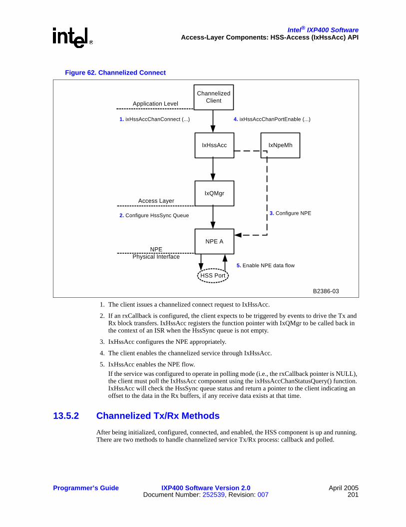
Intel® IXP400 SoftwareAccess-Layer Components: HSS-Access (IxHssAcc) API
Programmer’s Guide IXP400 Software Version 2.0 April 2005Document Number: 252539, Revision: 007 201
1. The client issues a channelized connect request to IxHssAcc.
2. If an rxCallback is configured, the client expects to be triggered by events to drive the Tx and Rx block transfers. IxHssAcc registers the function pointer with IxQMgr to be called back in the context of an ISR when the HssSync queue is not empty.
3. IxHssAcc configures the NPE appropriately.
4. The client enables the channelized service through IxHssAcc.
5. IxHssAcc enables the NPE flow. If the service was configured to operate in polling mode (i.e., the rxCallback pointer is NULL), the client must poll the IxHssAcc component using the ixHssAccChanStatusQuery() function. IxHssAcc will check the HssSync queue status and return a pointer to the client indicating an offset to the data in the Rx buffers, if any receive data exists at that time.
13.5.2 Channelized Tx/Rx MethodsAfter being initialized, configured, connected, and enabled, the HSS component is up and running. There are two methods to handle channelized service Tx/Rx process: callback and polled.
Figure 62. Channelized Connect
B2386-03
HSS Port
1. ixHssAccChanConnect (...)
Application Level
ChannelizedClient
IxHssAcc
IxQMgr
NPE A
Access Layer
NPEPhysical Interface
2. Configure HssSync Queue
IxNpeMh
3. Configure NPE
4. ixHssAccChanPortEnable (...)
5. Enable NPE data flow

Intel® IXP400 SoftwareAccess-Layer Components: HSS-Access (IxHssAcc) API
April 2005 IXP400 Software Version 2.0 Programmer’s Guide202 Document Number: 252539, Revision: 007
13.5.2.1 CallBack
If the pointer to the rxCallback() is not NULL when ixHssAccChanConnect() is called, an ISR will call rxCallback() to handle Tx/Rx data. It is called when each of N channels receives bytesPerTStrigger bytes.
Usually, a Rx thread is created to handle the HSS channelized service. The thread will be waiting for a semaphore. When rxCallback() is called by IxHssAcc, rxCallback() will put the information from IxHssAcc into a structure, and send a semaphore to the thread. Then rxCallback() returns so that IxHssAcc can continue its own tasks. The Rx thread — after receiving the semaphore — will wake up, take the parameters passed by rxCallback(), and perform Rx data processing, Tx data preparation, and error handling.
For Rx data processing, rxCallback() provides the offset value rxOffset to indicate where data is just written into each circular buffer. rxOffset is shared for all the circular buffers in the pool. The client has to make sure the Rx data are processed or moved to somewhere else before overwritten by the NPE since the buffers are circular.
For TX data preparation, rxCallback() provides the offset value txOffset to indicate which pointer list in the pointer lists pool is pointing to the data buffers currently being or will be transmitted. As a result, the client can use txOffset to determine where new data needs to be put into the data buffer pool for transmission. For example, data can be prepared and moved into buffers pointed by the (txOffset-2)th pointer list.
rxCallback() also provides the number of errors NPE receives. The client can call function ixHssAccLastErrorRetrievalInitiate() to initiate the retrieval of the last HSS error.
13.5.2.2 Polled
If the pointer to the rxCallback() is NULL when ixHssAccChanConnect() is called, it implies that the client will use a polling mechanism to detect when the Tx and Rx of channelized data is to occur. The client will use ixHssAccChanStatusQuery() to query whether channelized data has been received. If data has been received, IxHssAcc will return the details in the output parameters of ixHssAccChanStatusQuery.
ixHssAccChanStatusQuery() returns a flag dataRecvd that indicates whether the access component has any data for the client. If FALSE, the other output parameters will not have been written to. If it is TRUE, then rxOffset, txOffset, and numHssErrs — returned by ixHssAccChanStatusQuery() — are valid and can be used in the same way as in the callback function case above.
Figure 63 shows the Tx/Rx process.

Intel® IXP400 SoftwareAccess-Layer Components: HSS-Access (IxHssAcc) API
Programmer’s Guide IXP400 Software Version 2.0 April 2005Document Number: 252539, Revision: 007 203
1. After reading a configurable amount of data from the HSS port and writing the same amount of data to the HSSport, the NPE writes to the hssSync queue. There are two possible paths after that depending on how the client is connected:
2. Callback Mode
a. Through an interrupt, the IxQMgr component will callback IxHssAcc with details of the hssSync queue entry.
b. IxHssAcc will initiate the registered callback of the client.
OR
3. Polling Mode
a. The client will poll IxHssAcc using ixHssAccChanStatusQuery().
b. IxHssAcc will, in turn, poll IxQMgr’s hssSync queue for status.
c. If IxHssAcc reads an entry from the hssSync queue, it returns the details to the client.
Figure 63. Channelized Transmit and Receive
B2388-03
HSS Port
2a. Callback to IxHssAcc (rxOffset, txOffset, numHssErrs)
Application Level
ChannelizedClient
IxHssAcc
IxQMgr
NPE A
Access Layer
NPEPhysical Interface
1. NPE writes to HssSync Queue
2b. Callback to client (rxOffset, txOffset, numHssErrs)
or
or 3b. IxHssAcc polls for queue status. Returns (rxOffset, txOffset, numHssErrs)
3a. ixHssAccChanStatusQuery (...)
3c. Returns (rxOffset, txOffset, numHssErrs)

Intel® IXP400 SoftwareAccess-Layer Components: HSS-Access (IxHssAcc) API
April 2005 IXP400 Software Version 2.0 Programmer’s Guide204 Document Number: 252539, Revision: 007
13.5.3 Channelized DisconnectWhen the channelized service is not needed any more on a particular HSS port, ixHssAccChanPortDisable() is called to stop the channelized service on that port, then ixHssAccChanDisconnect() is called to disconnect the service.
13.6 HSS Packetized Operation
13.6.1 Packetized Connect and EnableixHssAccPktPortConnect()
After the HSS component is configured, ixHssAccPktPortConnect() has to be called to connect the client application with the packetized services. This function is responsible for connecting a client to one of the four available packetized ports on a configured HSS port.
There are four packetized services per HSS port, so this function has to be called once per packetized service.
Note: This functions structures have changed significantly in software release 2.0 and the function is no longer directly compatible with previous versions.
The client uses this function to:
• Pass data structures to configure the HDLC coprocessor
• Register a Rx call back function for Rx data processing
• Register a callback function to request more Rx buffers
• Register a callback function to indicate Tx done
• Pass a flag to turn HDLC processing on or off
The HDLC configuration structure sets up:
• What to transmit when an HDLC port is idle
• HDLC data endianness
• CRC type to be used for this HDLC port.
The parameters for ixHssAccPktPortConnect() include:
• IxHssAccHssPort hssPortId — The HSS port ID. There are two identical ports (0-1).
• IxHssAccHdlcPort hdlcPortId — This is the number of the HDLC port and it corresponds to the physical E1/T1 trunk (i.e., 0, 1, 2, 3).
• BOOL hdlcFraming — This value determines whether the service will use HDLC data or the raw data type (i.e., no HDLC processing).
• IxHssAccHdlcMode hdlcMode — This structure contains 56Kbps, HDLC-mode configuration parameters.
• BOOL hdlcBitInvert — This value determines whether bit inversion will occur between HDLC and HSS coprocessors (i.e., post-HDLC processing for transmit and pre-HDLC processing for receive, for the specified HDLC Termination Point).

Intel® IXP400 SoftwareAccess-Layer Components: HSS-Access (IxHssAcc) API
Programmer’s Guide IXP400 Software Version 2.0 April 2005Document Number: 252539, Revision: 007 205
• unsigned blockSizeInWords — The max tx/rx block size.• UINT32 rawIdleBlockPattern — Tx idle pattern in raw mode.• IxHssAccHdlcFraming hdlcTxFraming — This structure contains the following information
required by the NPE to configure the HDLC coprocessor for Tx.• IxHssAccHdlcFraming hdlcRxFraming — This structure contains the following information
required by the NPE to configure the HDLC coprocessor for Rx.• unsigned frmFlagStart — Number of flags to precede to transmitted flags (0-2).• IxHssAccPktRxCallback rxCallback — Pointer to the clients packet receive function. • IxHssAccPktUserId rxUserId — The client supplied Rx value to be passed back as an
argument to the supplied rxCallback.• IxHssAccPktRxFreeLowCallback rxFreeLowCallback — Pointer to the clients Rx-free-buffer
request function. If NULL, it is assumed client will free Rx buffers independently.• IxHssAccPktUserId rxFreeLowUserId — The client supplied RxFreeLow value to be passed
back as an argument to the supplied rxFreeLowCallback.• IxHssAccPktTxDoneCallback txDoneCallback — Pointer to the clients Tx done callback
function.• IxHssAccPktUserId txDoneUserId — The client supplied txDone value to be passed back as
an argument to the supplied txDoneCallback.
Now the HSS component can be enabled by calling ixHssAccPktPortEnable() with the port ID provided. Figure 64 shows what is done in IxHssAcc when the packetized service connect function is called.

Intel® IXP400 SoftwareAccess-Layer Components: HSS-Access (IxHssAcc) API
April 2005 IXP400 Software Version 2.0 Programmer’s Guide206 Document Number: 252539, Revision: 007
1. The client issues a packet service connect request to IxHssAcc.
2. IxHssAcc instructs IxQMgr to configure the necessary queues and register callbacks.
3. IxHssAcc configures the NPE with the HDLC parameters passed by the client.
4. The client enables the packet service.
5. IxHssAcc enables the NPE flow.
13.6.2 Packetized TxWhen the client has nothing to transmit, the HSS will transmit the idle pattern provided in the function ixHssAccPktPortConnect().
When the client has data for transmission, the client will call IX_OSAL_MBUF_POOL_GET() to get a IXP_BUF, put the data into the IXP_BUF using IX_OSAL_MBUF_MDATA(). If the client data is too large to fit into one buffer, multiple buffers can be obtained from the pool, and put into a chained buffers by using IX_OSAL_MBUF_PKT_LEN() and IX_OSAL_MBUF_NEXT_BUFFER_IN_PKT_PTR(). The whole chained buffer is passed to IxHssAcc for transmission by calling ixHssAccPktPortTx().
Figure 64. Packetized Connect
B2391-03
HSS Port
2. Configure queues. Configure Rx, RxFreeLow, TxDone callbacks.
Application Level
PacketizedClient
IxHssAcc
IxQMgr
NPE A
Access Layer
NPEPhysical Interface
1. ixHssAccPktPortConnect (...)
IxNpeMh
3. Configure NPE
4. ixHssAccPktPortEnable()
5. Enable NPE data flow

Intel® IXP400 SoftwareAccess-Layer Components: HSS-Access (IxHssAcc) API
Programmer’s Guide IXP400 Software Version 2.0 April 2005Document Number: 252539, Revision: 007 207
When the transmission is done, the TxDone call back function, registered with ixHssAccPktPortConnect(), is called, and the buffer can be returned to IXP_BUF pool using IX_OSAL_MBUF_POOL_PUT_CHAIN().
The following is example Tx code showing how to send an IXP_BUF:
The following is example Tx code showing how to chain IXP_BUFs together:
The process is shown in Figure 65.
IX_OSAL_MBUF *txBuffer;IX_OSAL_MBUF *txBufferChain = NULL;// get a IX_OSAL_MBUF(IXP_BUF)IX_OSAL_MBUF_POOL_GET(poolId, &txBuffer);// set the data length in the bufferIX_OSAL_MBUF_MLEN(txBuffer) = NumberOfBytesToSend;/* set the values to transmit */for (byteIndex = 0; byteIndex < IX_OSAL_MBUF_MLEN(txBuffer); byteIndex++)((UINT8 *)IX_OSAL_MBUF_MDATA(txBuffer))[byteIndex] =userData[byteIndex];//send the buffer outixHssAccPktPortTx (hssPortId, hdlcPortId, txBuffer);
IX_OSAL_MBUF *txBufferChain = NULL;IX_OSAL_MBUF *lastBuffer = NULL;if (txBufferChain == NULL) // the first buffer
txBufferChain = txBuffer;/* set packet header for buffer */IX_OSAL_MBUF_PKT_LEN(txBufferChain) = 0;
else // following buffers
IX_OSAL_MBUF_NEXT_BUFFER_IN_PKT_PTR(lastBuffer) = txBuffer;
// update the chain lengthIX_OSAL_MBUF_PKT_LEN(txBufferChain) +=
IX_OSAL_MBUF_MLEN(txBuffer);IX_OSAL_MBUF_NEXT_BUFFER_IN_PKT_PTR(txBuffer) = NULL;lastBuffer = txBuffer;// send the bubber outixHssAccPktPortTx (hssPortId, hdlcPortId, txBufferChain);

Intel® IXP400 SoftwareAccess-Layer Components: HSS-Access (IxHssAcc) API
April 2005 IXP400 Software Version 2.0 Programmer’s Guide208 Document Number: 252539, Revision: 007
1. The client presents an IXP_BUF to IxHssAcc for transmission.
2. IxHssAcc gets a transmit descriptor from its transmit descriptor pool, fills in the descriptor, and writes the address of the descriptor to the Tx queue.
3. The NPE reads a transmit descriptor from the Tx queue and transmits the data on the HSS port.
4. On completion of transmission, the NPE writes the descriptor to the TxDone queue.
5. IxHssAcc is triggered by this action, and the registered callback is executed. The descriptor is freed internally.
6. IxHssAcc initiates the TxDoneCallback on the client, passing it back its IXP_BUF pointer.
13.6.3 Packetized RxBefore packetized service is enabled, the Rx queue in the IxHssAcc component has to be replenished. This can be done by calling IX_OSAL_MBUF_POOL_GET() to get an IXP_BUF and calling ixHssAccPktPortRxFreeReplenish() to put the buffer into the queue. This is repeated until the queue is full.
Figure 65. Packetized Transmit
B2392-02
HSS Port
Application Level
PacketizedC lient
IxHssAcc
IxQ M gr
NPE A
Access Layer
NPEPhysical Interface
1. ixHssAccPktPortTx ( hssPortId, hdlcPortId , *m Buf for transm it data)
2. Descrip tor to Tx queue
3. NPE reads data from pointer in Tx queue, transm its data on HSS port.
4. M ove descriptor to TxDone queue
5. ixHssAccPktTxDoneCallback (*m Buf, num HssErrs, pktStatus, txDoneUserId)

Intel® IXP400 SoftwareAccess-Layer Components: HSS-Access (IxHssAcc) API
Programmer’s Guide IXP400 Software Version 2.0 April 2005Document Number: 252539, Revision: 007 209
Here is an example:
Usually, an Rx thread is created to handle the HSS packetized service, namely, to handle all the callback functions registered with ixHssAccPktPortConnect(). The thread will be waiting for a semaphore. When any one of the call back functions is executed by the HSS component, it will put the information from IxHssAcc into a structure, and send a semaphore to the thread. Then the callback function returns so that IxHssAcc can continues its own tasks. The Rx thread, after receiving the semaphore, will wake up, take the parameters from the structure passed by the callback function, and perform Rx data processing and error handling.
When data is received, rxCallback() is called. It passes the received data in the form of a IXP_BUF to the client. The IXP_BUF passed back to the client could contain a chain of IXP_BUF, depending on the packet size received. IX_OSAL_MBUF_NEXT_BUFFER_IN_PKT_PTR() can be used to get access to each of the IXP_BUF in the chained buffer, and IX_OSAL_MBUF_MDATA() can be used to get access to each data value. The IXP_BUF is returned to the buffer pool by using IX_OSAL_MBUF_POOL_PUT_CHAIN().
Here is an example:
rxCallback() also passes the packet status and the number of errors that NPE receives. The packet status is used to determine if the packet received is good or bad, and the client can call function ixHssAccLastErrorRetrievalInitiate() to initiate the retrieval of the last HSS error.
When the Rx buffer queue is running low, rxFreeLowCallback() is called. Then, the client can call IX_OSAL_MBUF_POOL_GET() and ixHssAccPktPortRxFreeReplenish() to fill up the Rx queue again.
// get a buffer
IX_OSAL_MBUF *rxBuffer;
rxBuffer = IX_OSAL_MBUF_POOL_GET(poolId);//IxHssAcc component needs to know the capacity of the IXP_BUFIX_OSAL_MBUF_MLEN(rxBuffer) = IX_HSSACC_CODELET_PKT_BUFSIZE;// give the Rx buffer to the HssAcc componentstatus = ixHssAccPktPortRxFreeReplenish (hssPortId, hdlcPortId, rxBuffer);
IX_OSAL_MBUF *buffer,IX_OSAL_MBUF *rxBuffer;// go through each buffer in the chained bufferfor (rxBuffer = buffer;
(rxBuffer != NULL) && (pktStatus == IX_HSSACC_PKT_OK);rxBuffer = IX_OSAL_MBUF_NEXT_BUFFER_IN_PKT_PTR(rxBuffer))
for (wordIndex =0;wordIndex<(IX_OSAL_MBUF_MLEN(rxBuffer) / 4);wordIndex++)
// get the values in the buffer IXP_BUFvalue = ((UINT32 *)IX_OSAL_MBUF_MDATA(rxBuffer))[wordIndex];// free the chained bufferIX_OSAL_MBUF_POOL_PUT_CHAIN(buffer);

Intel® IXP400 SoftwareAccess-Layer Components: HSS-Access (IxHssAcc) API
April 2005 IXP400 Software Version 2.0 Programmer’s Guide210 Document Number: 252539, Revision: 007
Alternatively, the client can use its own timer for suppling IXP_BUFs to the queue. This is the case if the pointer for rxFreeLowCallback() passed to ixHssAccPktPortConnect() is NULL.
The process is show in Figure 66.
1. When a complete packet is received, the Rx queue call-back function is invoked in an interrupt.
2. The descriptor is pulled from the Rx queue and the callback for this channel is invoked with the descriptor. The descriptor gets recycled.
3. The buffer is transmitted to the client.
4. When the RxFree queue is low, IxQMgr triggers an interrupt to IxHssAcc.
5. IxHssAcc triggers the client rxFreeLowCallback function, which was registered during the client connection process.
6. The client provides free IXP_BUFs for specific packetized channels.
7. Free IXP_BUFs are stored in the RxFree queue, and listed within the IxHssAcc Rx descriptors.
Figure 66. Packetized Receive
B 2 3 9 3 -0 3
H S S P o rt
A p p lica tio n L e ve l
P a c ke tize dC lie n t
Ix H ssA cc
IxQ M g r
N P E A
A cce ss L a ye r
N P EP h ys ica l In te rfa ce
4 . G e n e ra te in te rrru p t w h e n R x F re e q u e u e is lo w
5 . R xF re e L o w C a llb a ck
7 . R e p le n ish R xF re e q u e u e
6 . P ro v id e fre e m B u fs
1 . C o m p le te p a c ke t re c e iv e d a n d p ro c e s se d
2 . R e tr ie v e * m B u f fro m R x q u e u e
3 . R x C a llb a c k w ith * m B u f

Intel® IXP400 SoftwareAccess-Layer Components: HSS-Access (IxHssAcc) API
Programmer’s Guide IXP400 Software Version 2.0 April 2005Document Number: 252539, Revision: 007 211
13.6.4 Packetized DisconnectWhen packetized service channel is not needed any more, the function ixHssAccPktPortDisable() is called to stop the packetized service on that channel, and ixHssAccPktPortDisconnect() is called to disconnect the service.
This has to be done for each packet service channel. The client is responsible for ensuring all transmit activity ceases prior to disconnecting, and ensuring that the replenishment of the rxFree queue ceases before trying to disconnect.
13.6.5 56-Kbps, Packetized Raw ModeWhen a packet service channel is configured for 56-Kbps, packetized Raw mode, byte alignment of the transmitted data is not preserved. All raw data that is transmitted by a device using IxHssAcc in this manner will be received in proper order by the receiver (the external PHY device, for example). However, the first bit of the packet may be seen at any offset within a byte. All subsequent bytes will have the same offset for the duration of the packet. The same offset also applies to all subsequent packets received on the service channel as well.
The receive data path is identical to the scenario described above.
While this behavior will also occur for 56-Kbps, packetized HDLC mode, the HDLC encoding/decoding will preserve the original byte alignment at the receiver end.
13.7 Buffer Allocation Data-Flow OverviewPrior to connecting and enabling ports in IxHssAcc, a client must allocate buffers to the IxHssAcc component. IxHssAcc provides two services, packetized and channelized, and the clients exchange data with IxHssAcc differently for transmitting and receiving, depending on which service is chosen.
13.7.1 Data Flow in Packetized ServiceData in the time slots configured for HDLC or raw services will form packets for packetized service. IxHssAcc supports up to four packetized services per HSS port. The packetized service uses IXP_BUFs to store data, or chains IXP_BUFs together into chained IXP_BUFs for large packets.
The client is responsible for allocating these buffers and passing the buffers to IxHssAcc.

Intel® IXP400 SoftwareAccess-Layer Components: HSS-Access (IxHssAcc) API
April 2005 IXP400 Software Version 2.0 Programmer’s Guide212 Document Number: 252539, Revision: 007
An IXP_BUF pool should be created for packetized service by calling function IX_OSAL_MBUF_POOL_INIT() of the IxOsBuffMgt API with the IXP_BUF size and number of IXP_BUF needed. For example:
A IXP_BUF can be obtained from the pool by calling IX_OSAL_MBUF_POOL_GET(). This Buffer pool is shared by the Tx and Rx processes.
For Rx, before the packetized service is enabled, the Rx buffer queue in IxHssAcc has to be replenished. This can be done by calling ixHssAccPktPortRxFreeReplenish().
When packetized service starts, it is the client’s responsibility to ensure there is always an adequate supply of IXP_BUFs for the receive direction. This can be achieved in two ways. A call-back function can be registered with IxHssAcc to be called back when the free IXP_BUFs queue is running low. This call back function is registered with the IxHssAcc packetized service when ixHssAccPktPortConnect() is called. Alternatively, the client can use its own timer to regularly supply buffers to the queue.
The client also provides a receive call-back function to accept packets received through the HSS. After the data in the IXP_BUF is processed, IX_OSAL_MBUF_POOL_PUT_CHAIN() can be called to put the Rx buffer back into the IXP_BUF pool. The Rx packetized data flow is shown in Figure 67 on page 213.
IxHssAccCodeletMbufPool **poolIdPtr;
UINT32 numPoolMbufs;
UINT32 poolMbufSize;
*poolIdPtr = IX_OSAL_MBUF_POOL_INIT(numPoolMbufs, poolMbufSize,
"HssAcc Codelet Pool");

Intel® IXP400 SoftwareAccess-Layer Components: HSS-Access (IxHssAcc) API
Programmer’s Guide IXP400 Software Version 2.0 April 2005Document Number: 252539, Revision: 007 213
For Tx, buffers are allocated from the IXP_BUF pool by calling IX_OSAL_MBUF_POOL_GET(). Data for transmitting can be put into the IXP_BUF by using IX_OSAL_MBUF_MDATA(). If the client data is too large to fit into one buffer, multiple buffers can be obtained from the pool and made into a chained IXP_BUFs by using IX_OSAL_MBUF_PKT_LEN() and IX_OSAL_MBUF_NEXT_BUFFER_IN_PKT_PTR(). The whole chained IXP_BUF can be passed to IxHssAcc for transmission by calling ixHssAccPktPortTx().
A Tx callback function is also registered when ixHssAccPktPortConnect() is called before the service is enabled. When a chained IXP_BUF is done with transmitting, the callback function is called and the buffers can be returned to the IXP_BUF pool. The packetized Transmit data flow is described in Figure 68.
Figure 67. HSS Packetized Receive Buffering
NPE-AHss Packetized Rx
Operation
4. Data (HDLC frame or RAW block) for each packet-pipe written to appropriate mbuf, specified by descriptor. Steps 3 and 4 repeated to chain mbufs as required.
2. HDLC frame processing performed on each packet-pipe configured for HDLC mode
HssPacketizedRxFree0 -HssPacketizedRxFree3
queues3. Free descriptor read from packet- pipe-specific, "free" queue
1. Data received from HSS port
5. Descriptor returned when entire frame/ block received. If chaining, only first descriptor returned.
F0-TSa
F0-TSb
F0-TSc ... F0-
TSz
Frame 0
F1-TSa
F1-TSb
F1-TSc ... F1-
TSz
Frame 1
...
HSS Port Serial Data Stream(TSa, TSb, ... = timeslots configured as "HDLC")
IXP_BUFs
HssPacketizedRxqueue
B2382-03

Intel® IXP400 SoftwareAccess-Layer Components: HSS-Access (IxHssAcc) API
April 2005 IXP400 Software Version 2.0 Programmer’s Guide214 Document Number: 252539, Revision: 007
13.7.2 Data Flow in Channelized ServiceData in the time slots configured as Voice64K/Voice56K types will be provided to the client via the IxHssAcc channelized service. There are up to 32 such channels per HSS port. The channelized service uses memory that is shared between the Intel XScale core and the NPEs. The client is responsible for allocating the memory for IxHssAcc to transmit and receive data through the HSS port.
For receive, ixOsServCacheDmaAlloc() of the IxOSCacheMMU component can be used to create a pointer to a pool of contiguous memory from the shared memory of the Intel XScale core and the NPEs. The pointer to this Rx data pool needs to be a physical address because NPE will directly write data into this memory area. The memory pool is divided into N circular buffers, one buffer per channel. N is the total number of channels in service.
Figure 68. HSS Packetized Transmit Buffering
NPE-AHss Packetized Tx
Operation
2. Data (HDLC frame or RAW block) for each packet-pipe read from appropriate mbuf, specified by descriptor
3. HDLC frame processing performed on each packet-pipe configured for HDLC mode
HssPacketizedTx0 -HssPacketizedTx3
queues 1. Descriptor read from packet- pipe-specific, Tx queue
IXP_BUFs
4. Data transmitted to HSS port
HssPacketizedTxDonequeue
5. Descriptor returned when entire frame/ block sent.
F0-TSa
F0-TSb
F0-TSc ... F0-
TSz
Frame 0
F1-TSa
F1-TSb
F1-TSc ... F1-
TSz
Frame 1
...
HSS Port Serial Data Stream(TSa, TSb, ... = timeslots configured as "HDLC")
B2383-03

Intel® IXP400 SoftwareAccess-Layer Components: HSS-Access (IxHssAcc) API
Programmer’s Guide IXP400 Software Version 2.0 April 2005Document Number: 252539, Revision: 007 215
All the buffers have the same length. When the channelized service is initialized by ixHssAccChanConnect(), the pointer to the pool, the length of the circular buffers, and a parameter bytesPerTStrigger are passed to IxHssAcc, as well as a pointer to the an ixHssAccChanRxCallback() Rx callback function.
Figure 69 shows how the circular buffers are filled with data received though the HSS ports. When each of the N channels receive bytesPerTStrigger bytes, the Rx callback function will be called, and an offset value rxOffset is returned to indicate where data is written into the circular buffer. Note that rxOffset is shared for all the circular buffers in the pool. rxOffset is adjusted internally in the HSS component so that it will be wrapped back to the beginning of the circular buffer when it reaches the end of the circular buffer.
The client has to make sure the Rx data is processed or moved elsewhere before being overwritten by the HSS component. Hence the length of the circular buffers has to be chosen properly. The buffer need to be large enough for data to be read by the client and complete any possible in-place processing that would need to occur before the NPE rewrites over that memory. Understanding the client application’s read and processing latency, the size of the data unit needed by the client application for processing, and the rate at which the NPE writes data to a buffer at a given channel rate, are useful in making this calculation.
Figure 69 on page 216 shows the data flow of the channelized Receive service.

Intel® IXP400 SoftwareAccess-Layer Components: HSS-Access (IxHssAcc) API
April 2005 IXP400 Software Version 2.0 Programmer’s Guide216 Document Number: 252539, Revision: 007
For transmission, ixOsServCacheDmaMalloc() is used to allocated two pools: a data buffer pool and a pointer list pool. The data buffer pool has N buffers — one for each channel. Each buffer is divided into K sections and each section has L bytes. The pointer list pool has K pointer lists. Each list has N pointers, each pointing to a section in a data buffer.
Before channelized service is enabled, the pointers have to be initialized to point to the first section of each data buffer in the data buffer pool, and data for transmission is prepared and moved to the data buffer. The pointers to the data buffer pool and pointer list pool are passed to IxHssAcc when ixHssAccChanConnect() is called.
The client can check the current location of data being transmitted by using the registered ixHssAccChanRxCallback() function. When the Rx callback function is called, an offset value txOffset is returned.
txOffset indicates which pointer list in the pointer list pool is pointing to the sections of the data buffers currently being transmitted. Thus the client can use txOffset to determine where new data needs to be put into the data buffer pool for transmission. For example, data can be prepared and moved into sections pointed by the (txOffset-2)th pointer list. The length of the buffer, K * L, needs to be large enough so that the client has enough time to prepare data for transmission.
Figure 69. HSS Channelized Receive Operation
NPE-AHss Channelized Rx
Operation
2. Rx data moved to circular buffers, one for each channel
1. Rx data received from HSS port
HssChannelizedRxTriggerqueue
3. Trigger eventsent to queue atspecifiedfrequency
Client Rx Buffer in SDRAM
Total Size =(N+1)*CircBufSizeB
Circularbuffer forchannel 0RxCircBufSizeB
F0-TSaF1-TSaF2-TSa
F0-TSbF1-TSbF2-TSb
.. ... .
F0-TSzF1-TSzF2-TSz
.. .
...
Circularbuffer forchannel 1
Circularbuffer forchannel N
RxCircBufSizeB
RxCircBufSizeB
Channel:
F0-TSa
F0-TSb
F0-TSc ... F0-
TSz
Frame 0
0 1 2 N
F1-TSa
F1-TSb
F1-TSc ... F1-
TSz
Frame 1
0 1 2 N
...
HSS Port Serial Data Stream(TSa, TSb, ... = timeslots configured as "voice")
B2384-02

Intel® IXP400 SoftwareAccess-Layer Components: HSS-Access (IxHssAcc) API
Programmer’s Guide IXP400 Software Version 2.0 April 2005Document Number: 252539, Revision: 007 217
Figure 70. HSS Channelized Transmit Operation
...
Channel:
F0-TSa
F0-TSb
F0-TSc ... F0-
TSz
Fram e 0
0 1 2 N
F1-TSa
F1-TSb
F1-TSc ... F1-
TSz
Fram e 1
0 1 2 N
...
NPE-AH ssChannelized Tx
O peration
TxPtrC ircBufSizeB
...
C ircu lar bufferfor pointersto Tx-datab locks
F0-TSaF1-TSaF2-TSa
.. .
F irst Tx-datab lock forchannel 0
1. Tx data for each channel read using po inters in TxPtrC ircBuf
TxPtrC ircBuf
2. Tx data transm itted to HSS port
HSS Port Serial D ata Stream(TSa, TSb, ... = tim eslots configured as "voice")
PtrChN
PtrCh0PtrCh1PtrCh2
.. .
P trChN
PtrCh0PtrCh1PtrCh2
.. .P trChN
PtrCh0PtrCh1PtrCh2
.. .
.. ... .
SecondTx-datab lock forchannel 0
SecondTx-datablock forchannel 1
F0-TSzF1-TSzF2-TSz
.. .
F0-TSbF1-TSbF2-TSb
.. .
F irst Tx-datablock forchannel 1
First Tx-datablock forchannel N
B2385-02

This page is intentionally left blank.
Intel® IXP400 Software
April 2005 IXP400 Software Version 2.0 Programmer’s Guide218 Document Number: 252539, Revision: 007

Intel® IXP400 Software
Programmer’s Guide IXP400 Software Version 2.0 April 2005Document Number: 252539, Revision: 007 219
Access-Layer Components:NPE-Downloader (IxNpeDl) API 14
This chapter describes the Intel® IXP400 Software v2.0’s “NPE-Downloader API” access-layer component.
14.1 What’s NewThe following changes and enhancements were made to this component in software release 2.0:
• New NPE microcode images for NPE A were added to support the NPE-based Ethernet interface available on NPE A of the Intel® IXP46X Product Line. NPE A supports the same Ethernet-subsystem features as NPE B and NPE C.
• The NPE microcode images can now be built into a single binary file that can be placed on the target filesystem in Linux. This file can be loaded via a provided character device driver.
14.2 OverviewThe NPE downloader (ixNpeDl) component is a stand-alone component providing a facility to download a microcode image to NPE A, NPE B, or NPE C in the system. The IxNpeDl component defines the default library of NPE microcode images. An NPE microcode image is provided to support each IXP400 software release, and will contain up-to-date microcode for each NPE.
The IxNpeDl component also enables a client to supply a custom microcode image to use in place of the default images for each NPE. This “custom image” facility provides increased testability and flexibility, but is not intended for general use.
14.3 Microcode ImagesAll microcode images available for download to the NPEs are contained in a microcode image library. Each image contains a number of blocks of instruction, data, and state-information microcode that is downloaded into the NPE memory and registers. Each image also contains a download map that specifies how to extract the individual blocks of that image’s microcode.
Given a microcode image library in memory, the NPE Downloader can locate images from that image library in memory, extract and interpret the contained download map, and download the code accordingly.
Loading NPE Microcode from a File Versus Loaded from Memory
The NPE microcode library contains a series of NPE images. This microcode library can be compiled into the IXP400 software object code at build time, or it can take the form of a single binary file. The method of operation is defined at build time.

Intel® IXP400 SoftwareAccess-Layer Components: NPE-Downloader (IxNpeDl) API
April 2005 IXP400 Software Version 2.0 Programmer’s Guide220 Document Number: 252539, Revision: 007
The “Microcode from File” feature is only available for Linux. All other supported operating systems use obtain the NPE microcode from the compiled object code.
The purpose of providing the “Microcode from File” feature is to allow distribution of IXP400 software and the NPE microcode under different licensing conditions for Linux. Refer to the Intel® IXP400 Software Release Notes for further instructions on using this feature.
NPE Microcode Library Customization
The NPE microcode library contains a series of NPE images. By default, all of these are included in the build. However, some of these images may not be required, and as such may be taking up excess memory. To omit one or more specific images, the user needs to edit IxNpeMicrocode.h and follow the instructions within. Essentially, by “undefining” an NPE image identifier, the corresponding NPE image will be omitted from the overall build.
Note: If multiple image identifiers are provided for the same image, all of those identifiers need to be undefined to omit that image from the build.
NPE Image Compatibility
The software releases do not include tools to develop NPE software. The supplied NPE functionality is accessible through the APIs provided by the software release 2.0 library. The NPE images are provided in the form of a single.C file. Corresponding NPE image identifier definitions are provided in an associated header file. Both are incorporated as part of the software release package.
NPE microcode images are assumed compatible for only the specific release they accompany.
14.4 Standard Usage ExampleThe initialization of an NPE has been made relatively easy. Only one function call is required.
Users call the ixNpeDlNpeInitAndStart function, which loads a specified image and begins execution on the NPE. Here is a sample function call, which starts NPE C with Ethernet and Crypto functionality:
The parameter is a UINT32 that is defined in the NPE image ID definition. Table 42 lists the parameters for the standard images.
ixNpeDlNpeInitAndStart(IX_NPEDL_NPEIMAGE_NPEC_CRYPTO_ETH);

Intel® IXP400 SoftwareAccess-Layer Components: NPE-Downloader (IxNpeDl) API
Programmer’s Guide IXP400 Software Version 2.0 April 2005Document Number: 252539, Revision: 007 221
Table 42. NPE-A Images
Image Name Description
IX_NPEDL_NPEIMAGE_NPEA_HSS0 NPE Image ID for NPE-A with HSS-0 Only feature. It supports 32 channelized and 4 packetized.
X_NPEDL_NPEIMAGE_NPEA_HSS0_ATM_SPHY_1_PORT
NPE Image ID for NPE-A with HSS-0 and ATM feature. For HSS, it supports 16/32 channelized and 4/0 packetized. For ATM, it supports AAL 5, AAL 0 and OAM for UTOPIA SPHY, 1 logical port, 32 VCs.
IX_NPEDL_NPEIMAGE_NPEA_HSS0_ATM_MPHY_1_PORT
NPE Image ID for NPE-A with HSS-0 and ATM feature. For HSS, it supports 16/32 channelized and 4/0 packetized. For ATM, it supports AAL 5, AAL 0 and OAM for UTOPIA MPHY, 1 logical port, 32 VCs.
IX_NPEDL_NPEIMAGE_NPEA_ATM_MPHY_12_PORTNPE Image ID for NPE-A with ATM-Only feature. It supports AAL 5, AAL 0 and OAM for UTOPIA MPHY, 12 logical ports, 32 VCs.
IX_NPEDL_NPEIMAGE_NPEA_HSS_2_PORT NPE Image ID for NPE-A with HSS-0 and HSS-1 feature. Each HSS port supports 32 channelized and 4 packetized.
IX_NPEDL_NPEIMAGE_NPEA_DMA NPE Image ID for NPE-A with DMA-Only feature.
IX_NPEDL_NPEIMAGE_NPEA_WEP NPE Image ID for NPE-A with ARC4 and WEP CRC engines.
IX_NPEDL_NPEIMAGE_NPEA_ETH
NPE Image ID for NPE-A with Ethernet-Only feature. This image definition is identical to the image below: IX_NPEDL_NPEIMAGE_NPEA_ETH_LEARN_FILTER_SPAN_FIREWALL.
IX_NPEDL_NPEIMAGE_NPEA_ETH_LEARN_FILTER_SPAN_FIREWALL
NPE Image ID for NPE-A with Basic Ethernet Rx/Tx, which includes:
• MAC_FILTERING• MAC_LEARNING• SPANNING_TREE• FIREWALL
IX_NPEDL_NPEIMAGE_NPEA_ETH_LEARN_FILTER_SPAN_FIREWALL_VLAN_QOS
NPE Image ID for NPE-A with Basic Ethernet Rx/Tx, which includes:
• MAC_FILTERING• MAC_LEARNING• SPANNING_TREE• FIREWALL• VLAN/QoS
IX_NPEDL_NPEIMAGE_NPEA_ETH_SPAN_FIREWALL_VLAN_QOS_HDR_CONV
NPE Image ID for NPE-A with Basic Ethernet Rx/Tx, which includes:
• SPANNING_TREE• FIREWALL• VLAN/QoS• 802.3/802.11 Frame Header Conversion

Intel® IXP400 SoftwareAccess-Layer Components: NPE-Downloader (IxNpeDl) API
April 2005 IXP400 Software Version 2.0 Programmer’s Guide222 Document Number: 252539, Revision: 007
Table 43. NPE-B Images
Image Name Description
IX_NPEDL_NPEIMAGE_NPEB_DMA NPE Image ID for NPE-B with DMA-Only feature.
IX_NPEDL_NPEIMAGE_NPEB_ETH
NPE Image ID for NPE-B with Ethernet-Only feature. This image definition is identical to the image below: IX_NPEDL_NPEIMAGE_NPEB_ETH_LEARN_FILTER_SPAN_FIREWALL.
IX_NPEDL_NPEIMAGE_NPEB_ETH_LEARN_FILTER_SPAN_FIREWALL
NPE Image ID for NPE-B with Basic Ethernet Rx/Tx, which includes:
• MAC_FILTERING• MAC_LEARNING• SPANNING_TREE• FIREWALL
IX_NPEDL_NPEIMAGE_NPEB_ETH_LEARN_FILTER_SPAN_FIREWALL_VLAN_QOS
NPE Image ID for NPE-B with Basic Ethernet Rx/Tx, which includes:
• MAC_FILTERING• MAC_LEARNING• SPANNING_TREE• FIREWALL• VLAN/QoS
IX_NPEDL_NPEIMAGE_NPEB_ETH_SPAN_FIREWALL_VLAN_QOS_HDR_CONV
NPE Image ID for NPE-B with Basic Ethernet Rx/Tx, which includes:
• SPANNING_TREE• FIREWALL• VLAN/QoS• 802.3/802.11 Frame Header Conversion
Table 44. NPE-C Images (Sheet 1 of 2)
Image Name Description
IX_NPEDL_NPEIMAGE_NPEC_DMA NPE Image ID for NPE-C with DMA-Only feature.
IX_NPEDL_NPEIMAGE_NPEC_ETH
NPE Image ID for NPE-C with Eth-Only feature. This image definition is identical to the image below: IX_NPEDL_NPEIMAGE_NPEC_CRYPTO_ETH_LEARN_FILTER_SPAN_FIREWALL.
IX_NPEDL_NPEIMAGE_NPEC_CRYPTO_ETH_LEARN_FILTER_SPAN_FIREWALL
NPE Image ID for NPE-C with Basic Ethernet Rx/Tx, which includes:
• MAC_FILTERING• MAC_LEARNING• SPANNING_TREE• FIREWALL
IX_NPEDL_NPEIMAGE_NPEC_ETH_LEARN_FILTER_SPAN_FIREWALL_VLAN_QOS
NPE Image ID for NPE-C with Basic Ethernet Rx/Tx, which includes:
• MAC_FILTERING• MAC_LEARNING• SPANNING_TREE• FIREWALL• VLAN/QoS

Intel® IXP400 SoftwareAccess-Layer Components: NPE-Downloader (IxNpeDl) API
Programmer’s Guide IXP400 Software Version 2.0 April 2005Document Number: 252539, Revision: 007 223
14.5 Custom Usage ExampleUsing a custom image is the second option for starting an NPE. This feature is only useful to those parties that have NPE microcode development capabilities, and thus does not apply to most users. The majority of users will use the Intel-provided NPE library.
This allows the use of an external library of images, if needed. External libraries come in the form of a header file. The header file defines the image library as a single array of type UINT32, and it is that array symbol that should be used as the imageLibrary parameter for that function.
Here is the function used for this procedure:
14.6 IxNpeDl UninitializationAfter the first NPE has been started using one of the above methods, IxNpeDl will be initialized and the specified NPEs will begin execution.
IX_NPEDL_NPEIMAGE_NPEC_ETH_SPAN_FIREWALL_VLAN_QOS_HDR_CONV
NPE Image ID for NPE-C with Basic Ethernet Rx/Tx, which includes:
• SPANNING_TREE• FIREWALL• VLAN/QoS• 802.3/802.11 Frame Header Conversion
IX_NPEDL_NPEIMAGE_NPEC_CRYPTO_ETH_LEARN_FILTER_SPAN_FIREWALL
NPE Image ID for NPE-C with Basic Crypto and Basic Ethernet Rx/Tx, which includes:
• MAC_FILTERING• MAC_LEARNING• SPANNING_TREE• FIREWALL
For Crypto, it supports DES, SHA-1, MD5.
IX_NPEDL_NPEIMAGE_NPEC_CRYPTO_AES_ETH_LEARN_FILTER_SPAN_FIREWALL
NPE Image ID for NPE-C with AES Crypto and Basic Ethernet Rx/Tx, which includes:
• MAC_FILTERING• MAC_LEARNING• SPANNING_TREE• FIREWALL
For Crypto, it supports AES, DES, SHA-1, MD5. AES-CCM mode is not supported.
IX_NPEDL_NPEIMAGE_NPEC_CRYPTO_AES_CCM_ETHNPE Image ID for NPE-C with AES & AES-CCM Crypto and Basic Ethernet Rx/Tx. For Crypto, it supports AES, CCM, DES, SHA-1, MD5.
Table 44. NPE-C Images (Sheet 2 of 2)
Image Name Description
ixNpeDlCustomImageNpeInitAndStart(UINT32 *imagelibrary, UINT32 npeImageId);

Intel® IXP400 SoftwareAccess-Layer Components: NPE-Downloader (IxNpeDl) API
April 2005 IXP400 Software Version 2.0 Programmer’s Guide224 Document Number: 252539, Revision: 007
The IxNpeDl should be uninitialized prior to unloading an application module or driver. (This will unmap all memory that has been mapped by IxNpeDl.) If possible, IxNpeDl should be uninitialized before a soft reboot.
Here is a sample function call to uninitialize IxNpeDl:
Note: Calling ixNpeDlUnload twice or more in succession will cause all subsequent calls after the first one to exit harmlessly but return a FAIL status.
14.7 Deprecated APIsThe functions listed below have been deprecated and may be removed from a future software release of this component. Additionally, the functions listed below will not work with the new microcode image format provided in software release 2.0. As of software release 1.3, the functions ixNpeDlNpeInitAndStart and ixNpeDlCustomImageNpeInitAndStart have replaced the functions listed below:
• ixNpeDlImageDownload
• ixNpeDlAvailableImagesCountGet
• ixNpeDlAvailableImagesListGet
• ixNpeDlLatestImageGet
• ixNpeDlLoadedImageGet
• ixNpeDlMicrocodeImageLibraryOverride
ixNpeDlUnload();

Intel® IXP400 Software
Programmer’s Guide IXP400 Software Version 2.0 April 2005Document Number: 252539, Revision: 007 225
Access-Layer Components:NPE Message Handler (IxNpeMh) API 15
This chapter describes the Intel® IXP400 Software v2.0’s “NPE Message Handler API” access-layer component.
15.1 What’s NewThere are no changes or enhancements to this component in software release 2.0.
15.2 OverviewThis chapter contains the necessary steps to start the NPE message-handler component. Additionally, information has been included about how the Message Handler functions from a high-level view.
This component acts a pseudo service layer to other access components such as IxEthAcc. In the sections that describe how the messaging works, the “client” is an access component such as IxEthAcc. An application programmer will not need to do any coding to directly control message handling, just the initialization and uninitialization of the component.
The IxNpeMh component is responsible for sending messages from software components on the Intel XScale® Core to the three NPEs (NPE A, NPE B, and NPE C). The component also receives messages from the NPEs and passes them up to software components on the Intel XScale core. This encapsulates the details of NPE messaging in one place and provides a consistent approach to NPE messaging across all components. Message handling is a collaboration of Intel XScale core software (IxNpeMh) and the NPE software.
When sending a message that solicits a response from the NPE, the client must provide a callback to the IxNpeMh component to hand the response back. For unsolicited messages, the client should register appropriate callbacks with the IxNpeMh component to hand the messages back.
The IxNpeMh component relies on the IDs of solicited and unsolicited messages to avoid “over-lapping” and determine if a received message is solicited or unsolicited.
Each NPE has two associated data structures — one for unsolicited message callbacks and another for solicited message callbacks.
Messages are sent to the NPEs in-FIFOs, while messages are received from the NPEs out-FIFOs. Both the in-FIFO and out-FIFO have a depth of two messages, and each messages is two words in length.
When sending a message that solicits a response, the solicited callback is added to the end of the list of solicited callbacks. For solicited messages, the first ID-matching callback in the solicited callback list is removed and called. For unsolicited messages, the corresponding callback is retrieved from the list of unsolicited callbacks.

Intel® IXP400 SoftwareAccess-Layer Components: NPE Message Handler (IxNpeMh) API
April 2005 IXP400 Software Version 2.0 Programmer’s Guide226 Document Number: 252539, Revision: 007
The solicited callback list contains the list of callbacks corresponding to solicited messages not yet received from the NPE. The solicited messages for a given ID are received in the same order that those soliciting messages are sent, and the first ID-matching callback in the list always corresponds to the next solicited message that is received.
15.3 Initializing the IxNpeMhThe IxNpeMh has two modes of operation, interrupted or polled. This refers to how the IxNpeMh will receive messages from the NPEs. When an NPE has a message for the message handler, it will always send an interrupt to the IxNpeMh, but the IxNpeMh must be set up for interrupt driven operation for it to service the interrupt automatically.
15.3.1 Interrupt-Driven OperationThis is the preferred method of operation for the message handler. Here is a sample function call to initialize the IxNpeMh component for interrupt driven operation:
The function takes a yes/no value from an enum, and now all messages from all the NPEs will be serviced by IxNpeMH. The IxNpeMh handles messages from all NPEs and should only be initialized once.
15.3.2 Polled OperationHere is a sample function call to initialize the IxNpeMh component for interrupt driven operation:
The function takes a yes/no value from an enum, and now all messages from the NPEs must be manually checked. The IxNpeMh handles messages from all NPEs, and should only be initialized once.
After setting up polled operation the client must check for messages coming out of the NPEs. Here is a sample function call that will check to see if NPE-A has a message to send:
Three separate function calls are required to check all three of the NPEs.
Note: This function call cannot be made from inside an interrupt service routine as it will use resource protection mechanisms.
ixNpeMhInitialize (IX_NPEMH_NPEINTERRUPTS_YES);
ixNpeMhInitialize (IX_NPEMH_NPEINTERRUPTS_NO);
ixNpeMhMessagesReceive (IX_NPEMH_NPEID_NPEA);

Intel® IXP400 SoftwareAccess-Layer Components: NPE Message Handler (IxNpeMh) API
Programmer’s Guide IXP400 Software Version 2.0 April 2005Document Number: 252539, Revision: 007 227
15.4 Uninitializing IxNpeMhThe IxNpeMh should be uninitialized prior to unloading a kernel module (this will unmap all memory that has been mapped by IxNpeMh). If possible, IxNpeMh should also be uninitialized before a soft reboot.
Here is a sample function call to uninitialize IxNpeMh:
Note: IxNpeMh can only be initialized from an uninitialized state and can only be uninitialized from an initialized state. If this order is not followed, for example by uninitializing an uninitialized IxNpeMh, then unpredictable behavior will result. Calling any other IxNpeMh API functions after unloading will also cause unpredictable results.
15.5 Sending Messages from an Intel XScale® Core Software Client to an NPEAccess-layer components — such as ixEthAcc and ixHssAcc — do all of their own message handling. This section describes the process of how messages are sent and processed so someone who is using IxNpeMh can understand what is going on in the background and gain insight into some performance issues.
There are two types of messages to send to an NPE: unsolicited and solicited. The first is just a simple message — that is, all it does is send a block of data. The second type sends data, but also registers a function to handle a response from the NPE.
The following sections give an overview of the process.
15.5.1 Sending an NPE MessageThe scenario of sending a messages from an Intel XScale core software client to an NPE (as shown in Figure 71) is:
1. The client sends a message to the IxNpeMh component, specifying the destination NPE.
2. The IxNpeMh component checks that the NPE can accept a message.If not, the send will fail.
3. The IxNpeMh component sends the message to the NPE.
Note: If an NPE is busy, the message can be resent before the fail is returned. Because the action of rapidly messaging the NPE will consume the AHB bandwidth, the number of times the message will be sent is passed as a parameter to the send function; the default value is 3 (two retries).
ixNpeMhUnload();

Intel® IXP400 SoftwareAccess-Layer Components: NPE Message Handler (IxNpeMh) API
April 2005 IXP400 Software Version 2.0 Programmer’s Guide228 Document Number: 252539, Revision: 007
15.5.2 Sending an NPE Message with ResponseIn this case, the client’s message requires a response from the NPE. The scenario (as shown in Figure 72) is:
1. The client sends a message to the IxNpeMh component, specifying the destination NPE and a response callback.
2. The IxNpeMh component checks that the NPE can accept a message.If the component cannot accept a message, the send fails.
3. The IxNpeMh component adds the response callback to the end of the solicited callback list and sends the message to the NPE.
4. After some time, the NPEs “outFIFO not empty” interrupt invokes the IxNpeMh component’s ISR.
5. Within the ISR, the IxNpeMh component receives a message from the specific NPE.
6. The IxNpeMh component checks if this message ID has an unsolicited callback registered for it.If the messages has an unsolicited callback registered, the message is unsolicited. (See “Receiving Unsolicited Messages from an NPE to Client Software” on page 229.)
Figure 71. Message from Intel XScale® Core Software Client to an NPE
Client
IxNpeMh
NPE B NPE CNPE A
Customer / Demo Code
Access Driver
NPEs
1. Send Message
callback n+k...
callback n+1callback n
0x00 callback0x01 callback
...0xff callback
2. Send Message
B2395-01

Intel® IXP400 SoftwareAccess-Layer Components: NPE Message Handler (IxNpeMh) API
Programmer’s Guide IXP400 Software Version 2.0 April 2005Document Number: 252539, Revision: 007 229
7. Because this is a solicited message, the first ID-matching callback is removed from the solicited callback list and invoked to pass the message back to the client.If no ID-matching callback is found, the message is discarded and an error reported.
15.6 Receiving Unsolicited Messages from an NPE to Client SoftwareThe scenario of receiving unsolicited messages from an NPE to client software (as shown in Figure 73) is:
1. At initialization, the client registers an unsolicited callback for a particular NPE and a message ID.
2. After some time, the NPEs “outFIFO not empty” interrupt invokes the IxNpeMh component’s ISR.
3. Within the ISR, the IxNpeMh component receives a message from the specific NPE.
4. The IxNpeMh component determines if this message ID has an unsolicited callback registered for it.If the message ID does not have a registered unsolicited callback, the message is solicited. (See “Sending an NPE Message with Response” on page 228.)
Figure 72. Message with Response from Intel XScale® Core Software Client to an NPE
Client
IxNpeMh
NPE B NPE CNPE A
Customer / Demo Code
Access Driver
NPEs
1. Send Message
callback n+k...
callback n+1callback n
0x00 callback0x01 callback
...0xff callback
2. Save Callback
3. Send Message
6. Get Callback
7. Response Callback
4. Message Interrupt
5. Receive Message
B2396-01

Intel® IXP400 SoftwareAccess-Layer Components: NPE Message Handler (IxNpeMh) API
April 2005 IXP400 Software Version 2.0 Programmer’s Guide230 Document Number: 252539, Revision: 007
5. Since this is an unsolicited message, the IxNpeMh component invokes the corresponding unsolicited callback to pass the message back to the client.
The IxNpeMh component does not interpret message IDs. It only uses message IDs for comparative purposes, and for passing a received message to the correct callback function. This makes the IxNpeMh component immune to changes in message IDs.
The IxNpeMh component relies on the message ID being stored in the most-significant byte of the first word of the two-word message (IxNpeMhMessage).
Note: It is the responsibility of the client to create messages in the format expected by the NPEs.
Multiple clients may use the IxNpeMh component. Each client should take responsibility for handling its own range of unsolicited message IDs. (See the ixNpeMhUnsolicitedCallbackRegister.)
The IxNpeMh component handles messaging for the three NPEs independently. A problem or delay in interacting with one NPE will not impact interaction with the other NPEs.
Figure 73. Receiving Unsolicited Messages from NPE to Software Client
Client
IxNpeMh
NPE B NPE CNPE A
Customer / Demo Code
Access Driver
NPEs
1. Register Callback
callback n+k...
callback n+1callback n
0x00 callback0x01 callback
...0xff callback
2. Save Callback
5. Get Callback
6. Message Callback
3. Message Interrupt
4. Receive Message
B2397-01

Intel® IXP400 SoftwareAccess-Layer Components: NPE Message Handler (IxNpeMh) API
Programmer’s Guide IXP400 Software Version 2.0 April 2005Document Number: 252539, Revision: 007 231
15.7 DependenciesThe IxNpeMh component’s dependencies (as shown in Figure 74) are:
• Client software components must use the IxNpeMh component for messages to and from the NPEs.
• The IxNpeMh component must use IxOSAL for error-handling, resource protection, and registration of ISRs.
15.8 Error HandlingThe IxNpeMh component uses IxOSAL to report errors and warnings. Parameters passed to the IxNpeMh component are error-checked whenever possible. Interface functions of the IxNpeMh component return a status to the client, indicating success or failure.
The most important error scenarios — when using the IxNpeMh — are:
• Failure to send a message if the NPE is unable to accept one.
• Failure to receive a message if no suitable callback can be found.
• Failure to send a message implies there is some problem with the NPE. Failure to receive a message means the message will be discarded.
• To avoid message loss, clients should ensure that unsolicited callbacks are registered for all unsolicited message types.
Figure 74. ixNpeMh Component Dependencies
ixOsal
IxNpeMh
Client Software Component
Client Software Component
Client Software Component
B2398-02

This page is intentionally left blank.
Intel® IXP400 Software
April 2005 IXP400 Software Version 2.0 Programmer’s Guide232 Document Number: 252539, Revision: 007

Intel® IXP400 Software
Programmer’s Guide IXP400 Software Version 2.0 April 2005Document Number: 252539, Revision: 007 233
Access-Layer Components:Parity Error Notifier (IxParityENAcc) API 16
This chapter describes Intel® IXP400 Software v2.0’s “Parity Error Notifier (IxParityENAcc) API” access-layer component.
16.1 What’s NewThis is a new component for software release 2.0.
Note: The PCI support described in this chapter is not supported in software release 2.0.
16.2 IntroductionMany components in the IXP46X network processors provide parity error detection capabilities. These include:
• Instruction and Data Memory of the Network Processing Engines (NPEs)
• Switching Coprocessor in NPE B (SWCP)
• AHB Queue Manager SRAM (AQM)
• PCI Controller
• Expansion Bus Controller
• DDR SDRAM Memory Controller Unit (MCU). Additionally, the MCU on the IXP46X network processors provides Error Correction Code capabilities.
The IxParityENAcc access-layer component allows a client application to configure and enable/disable the parity error detection the blocks listed above on the Intel® IXP46X Product Line of Network Processors. It enables a client application to receive notification when a parity error is detected, along with information on the type and source of the error.
16.2.1 BackgroundThe processor or its external memory could be operating in an environment where bits in memory may be corrupted by electromagnetic radiation. All the above-mentioned blocks can be affected by unexpected corruptions. Errors that are not the result of a permanent hardware error, but are encountered as random errors in the state of individual memory cells, are called “soft errors”. Parity and ECC are mechanisms to detect and provide corrective or restorative action from these soft errors.

Intel® IXP400 SoftwareAccess-Layer Components: Parity Error Notifier (IxParityENAcc) API
April 2005 IXP400 Software Version 2.0 Programmer’s Guide234 Document Number: 252539, Revision: 007
For the purposes of this document, the following terms will be used as defined below.Error Correction Logic/Error Correction Code
The Error Correction Logic in the Memory Controller Unit (MCU) generates the ECC code (which requires additional bits for the code word) for DDR SDRAM reads and writes. For reads, this logic compares the ECC code read with the locally generated ECC code. If the codes do not match, then the Error Correction Logic determines the error type. For a single-bit error, this block determines which bit resulted in the error and corrects the error before the data is presented onto the bus. However, the error still remains in the memory location and needs to be fixed by writing the corrected data to the memory location. For writes, ECC logic in the MCU generates the ECC and sends it with the data to the memory.
Scrubbing/Memory Scrub
Scrubbing is the process of correcting an error in a memory location. When the MCU detects an error during a read, the MCU logs the address where the error occurred and interrupts the Intel XScale core. The Intel XScale core must then write back to the memory location to fix the error through a software handler. Note that the scrub rectifies only single-bit parity errors detected by the DDR MCU.
Parity Error Context
This refers to the type of the parity error, the source of the parity error (i.e., the block which has the parity error) and the address of the failed word where applicable. The IxParityENAcc API provides a Parity Error Context to the client application when a parity or ECC error is detected.
Parity and Error Correction Code
Parity error detection is a simple and reliable mechanism to detect a single-bit error in a memory location. In general this mechanism is implemented by using an additional single bit along with the data bits in a memory location so that the bits set are of even/odd number and there is an even/odd number of ‘1’s in the memory location. The MCU hardware will also detect multiple bit errors, but cannot detect whether the MCU is configured for odd or even parity.
16.2.2 Parity and ECC Capabilities in the Intel® IXP45X and Intel® IXP46X Product LineThe IXP46X network processors can detect a variety of parity or ECC errors. The individual hardware blocks raise an interrupt to notify the Intel XScale core about these failures. The interrupt controller on IXP46X network processors has a set of interrupts classified as ‘error’ class. These interrupts take unconditional high-priority from the normal positional priority interrupts. This section summarizes the interrupt behavior as it applies when a parity or ECC error is detected.
Note: For detailed information regarding the specific parity and ECC capabilities and interrupt mechanisms of IXP46X network processors, refer to the Intel® IXP46X Product Line of Network Processors Developer’s Manual.
16.2.2.1 Network Processing Engines
The NPE will lock and cease to operate immediately when affected by a parity error in its internal memories or due to external errors in coprocessors (AHB Coprocessor, or Switching Coprocessor). External NPE ports will be disabled. An interrupt is sent to the Intel XScale core through the interrupt controller, and the parity context will provide information on whether the interrupt is related to internal memory parity errors or an external coprocessor error.

Intel® IXP400 SoftwareAccess-Layer Components: Parity Error Notifier (IxParityENAcc) API
Programmer’s Guide IXP400 Software Version 2.0 April 2005Document Number: 252539, Revision: 007 235
16.2.2.2 Switching Coprocessor in NPE B (SWCP)
The Switching Coprocessor generates 8-bit parity – 1 bit per each byte of the 64 bit (8-byte) entries in its SRAM. These parity bits will be generated and captured along with the 64 bits of data during a write operation. The subsequent read operation will again generate parity bits from the 64 bits of data and compare against the ones stored. If there is a mismatch, an interrupt is issued to the Intel XScale core through the interrupt controller.
A parity error in this component would also generate an NPE-B interrupt as an external coprocessor error.
16.2.2.3 AHB Queue Manager (AQM)
The AQM, on identifying a parity error from its internal memory, will return an ‘AHB Error’ response on the AHB bus to the requesting master. The interrupt context then refers to the address of either a queue entry or queue configuration entry, whose access resulted in failure. For queue entry address cases, the client application should treat the queue entry as invalid. The client should respond to a queue configuration parity error by rendering the entire queue invalid.
16.2.2.4 DDR SDRAM Memory Controller Unit (MCU)
When the MCU detects a single-bit error, the word is corrected before it is delivered so that the Intel XScale core gets a correct copy of the defective memory location contents (which still contains the uncorrected value). For multiple-bit errors, no correction is possible and an error response is placed on the bus visible to the Intel XScale core. In either case the interrupt context refers to the address of the access that failed. The MCU keeps track of two such parity errors at any point in time and notifies of an overflow if more than two parity errors occurred at the same time, in which case the address will not be logged.
16.2.2.5 Expansion Bus Controller
The Expansion Bus Controller, upon receiving a parity error on the Expansion Bus, terminates the transaction and responds on the South AHB bus with an “AHB Error” response for an outbound read initiated by an internal master. It will respond similarly in situations where an inbound write is initiated by an external master. It then provides an interrupt to the Intel XScale core with a context containing a reference to the address of the access that contained the invalid data.
16.2.2.6 PCI Controller
The PCI Controller will send an interrupt to the Intel XScale core upon detecting a parity error in the following scenarios:
• read and write data transfers from AHB devices to PCI
• write data transfer from PCI to AHB devices.
For a read transaction initiated from PCI onto AHB, the MCU would detect any parity errors and send an interrupt to the Intel XScale core.

Intel® IXP400 SoftwareAccess-Layer Components: Parity Error Notifier (IxParityENAcc) API
April 2005 IXP400 Software Version 2.0 Programmer’s Guide236 Document Number: 252539, Revision: 007
16.2.2.7 Secondary Effects of Parity Interrupts
If the Intel XScale core detects an error on the AHB bus or on its private DDR memory interface (MPI), an exception will be generated that will be serviced by its fault handler (such as data abort, or prefetch abort exception handler). The MCU will also generate a parity interrupt in this case.
Caution: There is no guarantee as to the arrival order at the Intel XScale core of the data abort notification versus the parity interrupt. The client application should respond accordingly. For guidance in resolving the race condition between the data abort and the interrupt, refer to the scenarios described in “Parity Error Notification Detailed Scenarios” on page 242.
The AHB-AHB bridge unit, upon receiving an “AHB Error” from the South AHB caused by a parity error from a South AHB device, will respond with an AHB error to the originating master (an NPE) on the North AHB. The AHB Coprocessor in the NPE will abort the transaction and assert an error condition to the NPE, which will cause the NPE to lock up. This will result in an NPE external coprocessor interrupt event to the Intel XScale core, as described in “Network Processing Engines” on page 234.
An NPE will report an ‘external’ error in the situation described above even though the chain of events started with a parity error on a South AHB device (such as an AQM, Expansion Bus Controller).
16.2.3 Interrupt PrioritizationTable 45 shows the list of interrupts that the Intel XScale core would receive in the event of a parity error. IxParityENAcc applies only the software defined priority as indicated; the top priority being the priority 0 of the MCU.
Table 45. Parity Error Interrupts
Interrupt Bit1 Default Priority2Software Defined Priority3
Source Description
Int0 0 1 NPE-A IMEM, DMEM or External Errors
Int1 1 2 NPE-B IMEM, DMEM or External Errors4
Int2 2 3 NPE-C IMEM, DMEM or External Errors
Int8 8 6 PCI PCI Interrupt5
Int58 58 4 SWCP Switching Coprocessor Interrupt 4
Int60 60 5 AQM AHB Queue Manager Interrupt
Int61 61 0 MCU Single or Multi-Bit ECC Error. Multi-bit is serviced first in IxParityENAcc.
Int62 62 7 EXP Expansion Bus Parity Error
NOTES:1. Interrupts 32-61 are higher-priority (error class) interrupts than 0-31. For example, MCU interrupt will take priority over
NPE…even though the “Default Priority” table suggests otherwise.2. The interrupt controller applies the default priorities and accordingly asserts the parity error interrupts to the Intel XScale
core.3. The software defined priority is implemented by the access layer and is predefined.4. A SWCP interrupt is also seen as an NPE-B external interrupt.5. PCI Interrupts are those generated by the PCI Interrupt controller, and not the PCI Interrupt lines A,B,C and D.

Intel® IXP400 SoftwareAccess-Layer Components: Parity Error Notifier (IxParityENAcc) API
Programmer’s Guide IXP400 Software Version 2.0 April 2005Document Number: 252539, Revision: 007 237
16.3 IxParityENAcc API Details
16.3.1 FeaturesThe parity error access component provides the following features:
• Interface to the client application to register a call back handler for application-specific processing with respect to the source of failure in the notification.
• Interface to the client application to individually enable and disable parity detection in the following hardware blocks, which are capable of generating parity errors. This interface can be invoked multiple times either to enable/disable or query parity error detection capabilities.
— Instruction and Data Memory of the Network Processing Engines (NPEs)
— Switching coprocessor in NPE B (SWCP)
— AHB Queue Manager’s SRAM (AQM)
— PCI Controller
— Expansion Bus Controller
— DDR SDRAM Memory Controller Unit (MCU).
• Interface to query the parity error detection status (whether enabled or not) on each of the above components.
• Interface to get the parity error detection statistics for each of the above-mentioned components.
• Interface exchanges the data structures defined in the host byte order with the client application. This module operates in both big endian and little endian mode.
16.3.2 DependenciesThe client application at the time of initialization registers the parity error handler callback with IxParityENAcc. The client application also makes use of the parity error detection API to enable the underlying hardware blocks for parity error detection.
Table 46. Parity Capabilities Supported by IxParityENAcc
Feature Hardware Component Software Support Recoverable
Error Correction Code Memory Controller Unit - SDRAMSingle Bit Parity Error Notification Yes
Multi-Bit Parity Error Notification No
Parity Error Detection AHB Queue Manager SRAM Parity Error Notification No
Parity Error DetectionNPE IMEM, DMEM, AHB Coprocessor, Switch Coprocessor
Parity Error Notification No
Parity Error Detection Switch Coprocessor Parity Error Notification No
Parity Error Detection PCI Controller Parity Error Notification No
Parity Error Detection Expansion Bus Controller Parity Error Notification No

Intel® IXP400 SoftwareAccess-Layer Components: Parity Error Notifier (IxParityENAcc) API
April 2005 IXP400 Software Version 2.0 Programmer’s Guide238 Document Number: 252539, Revision: 007
IxParityENAcc depends on various hardware registers to fetch the parity error information upon receiving an interrupt due to parity error. It then notifies the client application through the means of the callback handler with parity error context information.
IxParityENAcc also makes use of IxOSAL to access the underlying Operating System features such as IRQ registration, locks, and register access. IxOSAL is an abstracted interface, which is portable across different underlying OS.
Please note that the client application may have dependencies on other access components when attempting to resolve the parity error issues. Indirect dependencies are not captured here.
Figure 75 presents a IxParityENAcc Dependency diagram.
16.4 IxParityENAcc API Usage Scenarios
The following scenarios present usage examples of the interface by a client application.
There are three general tasks that would normally be provided by a client application with respect to parity events:
• Parity Error Notification
Figure 75. IxParityENAcc Dependency Diagram
B4383-01
NPE A
Parity Error Notifier Access Component
SWCPAQM
DDR MCU
PCI Bus Controller
Expansion Bus Ctrl
Client Application
Parity Error Configuration
Parity Error Notification
Interrupt Controller
IxOSAL
IxFeatureCtrlAcc
NPE B
NPE C
Hardware Interface
Access-Layer Interface
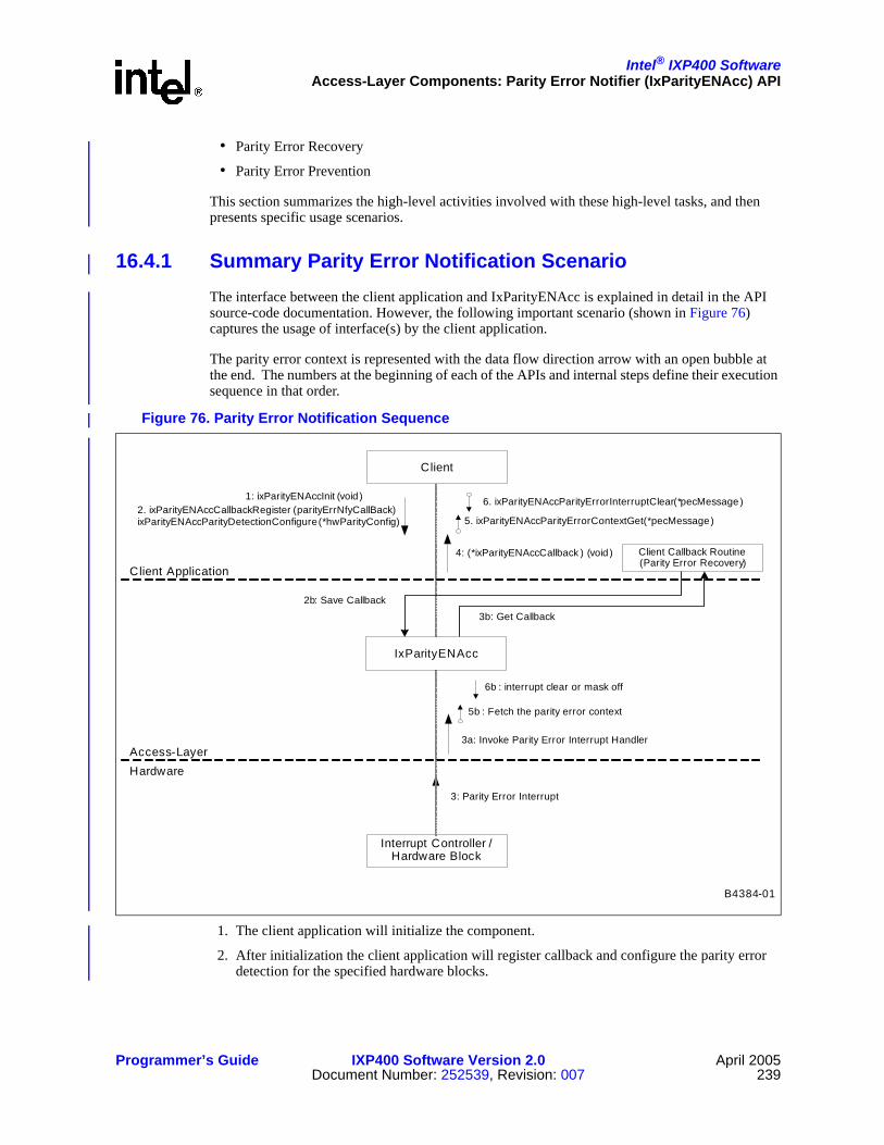
Intel® IXP400 SoftwareAccess-Layer Components: Parity Error Notifier (IxParityENAcc) API
Programmer’s Guide IXP400 Software Version 2.0 April 2005Document Number: 252539, Revision: 007 239
• Parity Error Recovery
• Parity Error Prevention
This section summarizes the high-level activities involved with these high-level tasks, and then presents specific usage scenarios.
16.4.1 Summary Parity Error Notification ScenarioThe interface between the client application and IxParityENAcc is explained in detail in the API source-code documentation. However, the following important scenario (shown in Figure 76) captures the usage of interface(s) by the client application.
The parity error context is represented with the data flow direction arrow with an open bubble at the end. The numbers at the beginning of each of the APIs and internal steps define their execution sequence in that order.
1. The client application will initialize the component.
2. After initialization the client application will register callback and configure the parity error detection for the specified hardware blocks.
Figure 76. Parity Error Notification Sequence
B4384-01
Client Application
Access-Layer
4: (*ixParityENAccCallback ) (void )
3: Parity Error Interrupt
Client
Interrupt Controller /Hardware Block
Client Callback Routine(Parity Error Recovery)
Hardware
3a: Invoke Parity Error Interrupt Handler
5b : Fetch the parity error context
1: ixParityENAccInit (void )2. ixParityENAccCallbackRegister (parityErrNfyCallBack)ixParityENAccParityDetectionConfigure(*hwParityConfig) 5. ixParityENAccParityErrorContextGet(*pecMessage)
6. ixParityENAccParityErrorInterruptClear(*pecMessage)
2b: Save Callback3b: Get Callback
6b : interrupt clear or mask off
IxParityENAcc

Intel® IXP400 SoftwareAccess-Layer Components: Parity Error Notifier (IxParityENAcc) API
April 2005 IXP400 Software Version 2.0 Programmer’s Guide240 Document Number: 252539, Revision: 007
3. When a parity error occurs, the interrupt will fire and invoke the ISR of the IxParityENAcc component.
4. IxParityENAcc, in turn, invokes the client callback.
5. The client or data abort handler callback routine will then fetch the parity error context details and take appropriate action.
6. The client will then request to clear the interrupt condition.
The Parity Error Context will provide the following details:
• Source where the parity error detected
• Access type – Read/Write
• Faulty memory address
• Data from the faulty location if available
• Interface on which the request is made (AHB Bus or MPI)
• Master and Slave of the last erroneous AHB transaction
Table 47 describes the actions that should be taken when the client callback or data abort handler invokes the API to clear the parity interrupt conditions for the specified parity error context.
Table 47. Parity Error Interrupt Deassertion Conditions (Sheet 1 of 2)
Interrupt Bit Source API Invoked by... Action Taken During Interrupt Clear
Int0Int1Int2
NPE-ANPE-BNPE-C
Client callback
Interrupt will be masked off at the interrupt controller so that it will not trigger continuously. Client application has to take appropriate action and needs to reconfigure the parity error detection subsequently so that it is notified of the interrupts.
Int8 PCI Client Callback
Interrupt condition is cleared at the PCI bus controller for the following:- PCI Initiator- PCI Target
Int58 SWCP Client Callback
Interrupt will be masked off at the interrupt controller so that it will not trigger continuously. Client application has to take appropriate action and needs to reconfigure the parity error detection subsequently so that it is notified of the interrupts.

Intel® IXP400 SoftwareAccess-Layer Components: Parity Error Notifier (IxParityENAcc) API
Programmer’s Guide IXP400 Software Version 2.0 April 2005Document Number: 252539, Revision: 007 241
16.4.2 Summary Parity Error Recovery ScenarioIxParityENAcc does not perform parity error recovery tasks. This should be done by the client application.
When notified of any failure, the client application should identify the affected components by calling a function to fetch the Parity Error Context and decide on the appropriate course of action considering the impact on its functionality. For example:
• Reset the whole system immediately.
• Graceful shutdown of the system after taking the necessary actions to minimize the impact (informing the peers that it is about to shut down, tear down communication channels, etc.)
• Other means, depending on the application and data integrity requirements.
The internal memories of NPEs, the Switching Coprocessor and AHB Queue Manager do not provide for an error correction facility. The DDR SDRAM controller implements a single-bit error correction mechanism that requires the Intel XScale core to read and write the faulty memory location.
When the DDR controller notifies the Intel XScale core about an error, error handling may vary slightly, depending on the operating system and Intel XScale core MMU configurations. The user application should provide a scrub routine for single-bit parity errors. This routine will be responsible for disabling interrupts, memory mapping, flushing of cache lines before reading the faulty word and after writing back the correct word onto it and finally enabling the interrupts.
Int60 AQM Client Callback
Interrupt will be masked off at the interrupt controller so that it will not trigger continuously. Client application has to take appropriate action and needs to reconfigure the parity error detection subsequently so that it is notified of the interrupts.
Int61 MCU Client Callback of Data Abort Handler
Parity interrupt condition is cleared at the SDRAM MCU for the following:
• Single-bit • Multi-bit• Overflow condition, i.e., more than
two parity conditions occurred.Note that single-parity errors do not result in data abort and not all data aborts are caused by multi-bit parity error. Refer to “Parity Error Notification Detailed Scenarios” on page 242.
Int62 EXP Client Callback
Parity interrupt condition is cleared at the Expansion Bus Controller for the following:
• External master initiated Inbound write
• Internal master (IXP46X network processors) initiated Outbound read.
Table 47. Parity Error Interrupt Deassertion Conditions (Sheet 2 of 2)
Interrupt Bit Source API Invoked by... Action Taken During Interrupt Clear

Intel® IXP400 SoftwareAccess-Layer Components: Parity Error Notifier (IxParityENAcc) API
April 2005 IXP400 Software Version 2.0 Programmer’s Guide242 Document Number: 252539, Revision: 007
For multi-bit parity errors, no error correction is possible and the Intel XScale core will be notified. The client application should handle such notifications.
16.4.3 Summary Parity Error Prevention ScenarioIxParityENAcc does not perform parity error prevention tasks. This should be done by the client application.
Since the DDR SDRAM controller provides the facility to correct single-bit parity errors, it is possible to run a background process/task to read the SDRAM locations at regular intervals and to fix the single-bit parity errors when encountered. This may be beneficial by reducing the chance of parity problems affecting the application code.
Note: In order to scrub single-bit parity error notification due to a read transaction, the scrub routine should first disable single-bit parity error detection and then perform a read and write access onto the faulty memory location. Otherwise the read memory access will result in another single-bit parity error notification and will result in an infinite number of iterations.
The scrub routine should ignore single-bit parity errors notified due to write transactions since the MCU will have scrubbed the data during the write transaction itself.
16.4.4 Parity Error Notification Detailed ScenariosThis section describes recommended usage of the IxParityENAcc component in several interrupt scenarios involving data aborts and parity error interrupts. The scenarios and possible implementations provided here are from the client application perspective only, and could be resolved in an alternate manner. It is the client application’s responsibility to implement an enhanced/modified data abort exception handler and the callback routine.
Note that the treatment of prefetch aborts may be very similar to that of data aborts, and is not described separately.
An Intel XScale core access will result in data abort after experiencing problems in address translation, memory access protection, etc. These data aborts may not be specifically related to a parity error. In some situations, however, a parity error will also cause a data abort. Intel XScale core accesses of South AHB bus targets that receive an AHB error response will result in a data abort. For example, an attempt to read from the AQM or Expansion Bus results in an AHB error response due to parity error at the AQM/Expansion Bus Controller.
Any non-Intel XScale core access to faulty SDRAM memory will result in the Parity Error notification reaching the Intel XScale core, but will not cause a data abort. However, an Intel XScale core access to an SDRAM memory location that has a multi-bit parity problem will always result in the MCU triggering a Data Abort and may also result in a multi-bit Party Error notification if the MCU is configured to detect the parity error.
The parity error context information also include details of the last error observed on the AHB bus. The information provided may be of help for the client application to decide which course of action to take. This information is retrieved from a Performance Monitoring Unit register, which might have been overwritten by another error by the time it is retrieved. The PMU may or may not include the information related to the parity event. This is because it may include data from previous errors. For example, an AHB transaction error has been locked into the PMU register, or there may be a parity event and the register data was retrieved or cleared by another process.

Intel® IXP400 SoftwareAccess-Layer Components: Parity Error Notifier (IxParityENAcc) API
Programmer’s Guide IXP400 Software Version 2.0 April 2005Document Number: 252539, Revision: 007 243
It is important to note that if an interrupt condition is not cleared then it will result in the parity interrupt being triggered again.
Figure 77–Figure 83 show the process flow that occurs in several data abort and parity error scenarios.
Figure 77. Data Abort with No Parity Error
Figure 78. Parity Error with No Data Abort
B4380-01
Data Abort IxParityENAcc Client Callback
IxParityENAccParityErrorContextGet (*pecMessage)No parity detected whenData Abort occurred.IX_PARITYENACC_NOPARITY
B4385-01
Data Abort IxParityENAcc Client Callback
IxParityENAccParityErrorContextGet(*pecMessage)
(*IxParityENAccCallback )()
IxParityENAccParityErrorInterruptClear(*pecMessage)
IX_PARITYENACC_SUCCESS
IX_PARITYENACC_SUCCESS

Intel® IXP400 SoftwareAccess-Layer Components: Parity Error Notifier (IxParityENAcc) API
April 2005 IXP400 Software Version 2.0 Programmer’s Guide244 Document Number: 252539, Revision: 007
In order to avoid a race condition between the data abort handler and the parity error callback, delay has been introduced in the MCU parity event interrupt service routine of the access-layer component. This allows the data abort handler to complete prior to the interrupt service routine returning the parity context information.
Figure 79. Data Abort followed by Unrelated Parity Error Notification
Figure 80. Unrelated Parity Error Followed by Data Abort
B4381-01
Interrupt-2
Interrupt-1
Data Abort IxParityENAcc Client Callback
IxParityENAccParityErrorContextGet(*pecMessage)
IxParityENAccParityErrorInterruptClear(*pecMessage)
IX_PARITYENACC_SUCCESS
ExamineParityErrorSource
Data abort ignores the non related parity errorsince the multi-bit parity error is due to accessby masters other than XScale.
NOTE: Software applied the priority to selectthe multi-bit parity interrupt first.
(*IxParityENAccCallback )()
IxParityENAccParityErrorContextGet(*pecMessage)
IX_PARITYENACC_SUCCESS
IX_PARITYENACC_SUCCESS
Gets Parity Interrupt Status:
Source = Multi-bitAddress = [Multi-bit]
Gets Parity Interrupt Status:
Source = Multi-bitAddress = [Multi-bit]
Both multi and single-bitparity error on the MCU detected due to non XScale access when Data Abort occurred.
IxParityENAccParityErrorInterruptClear(*pecMessage)
(*IxParityENAccCallback )()
IxParityENAccParityErrorContextGet(*pecMessage)
IX_PARITYENACC_SUCCESS
IX_PARITYENACC_SUCCESS
Gets Parity Interrupt Status:
Source = Single-bitAddress = [Single-bit]
B4386-01
Data Abort IxParityENAcc Client Callback
(*IxParityENAccCallback )()
IxParityENAccParityErrorInterruptClear(*pecMessage)
IxParityENAccParityErrorContextGet(*pecMessage)
IxParityENAccDAParityErrorContextGet(*pecMessage)
IX_PARITYENACC_SUCCESS
DelayMaxDATriggerTime
ExamineParityErrorSource
IX_PARITYENACC_SUCCESS
IX_PARITYENACC_SUCCESS
Gets ParityInterrupt Status:
Source = NPEAddress = [X]
Gets ParityInterrupt Status:
Source = NPEAddress = [X]
Non-MCU (E.g.,NPE) parityerror detected when Data Abort occurred.
Data abort ignores the non related parity error.

Intel® IXP400 SoftwareAccess-Layer Components: Parity Error Notifier (IxParityENAcc) API
Programmer’s Guide IXP400 Software Version 2.0 April 2005Document Number: 252539, Revision: 007 245
This scenario shown in Figure 83 can occur because the order in which the interrupts are triggered for a parity error and a related data abort are not guaranteed.
Figure 81. Data Abort Caused by Parity Error
Figure 82. Parity Error Notification Followed by Related Data Abort
B4382-01
Data Abort IxParityENAcc Client Callback
IxParityENAccParityErrorContextGet(*pecMessage)
IxParityENAccParityErrorInterruptClear(*pecMessage)
IX_PARITYENACC_SUCCESS
IX_PARITYENACC_SUCCESS
Gets Parity Interrupt Status:
Source = Multi-bitAddress = [Multi-bit ]
Clear ParityInterrupt:
Source = Multi-bitAddress = [Multi-bit ]
Multi-bit parity erroron MCU detected when Data Abort occurred.
Parity Interrupt will not fire.
B4387-01
Data Abort IxParityENAcc Client Callback
IxParityENAccDAParityErrorContextGet(*pecMessage)
IxParityENAccDAParityErrorInterruptClear(*pecMessage)
(*IxParityENAccCallback )()
IxParityENAccParityErrorContextGet(*pecMessage)
DelayMaxDATriggerTime
IX_PARITYENACC_SUCCESS
IX_PARITYENACC_SUCCESS
IX_PARITYENACC_NOPARITY
Gets Parity Interrupt Status:
Source = Multi-bitAddress = [Multi-bit]
Clear ParityInterrupt:
Source = Multi-bitAddress = [Multi-bit]
Multi-bit parity erroron MCU observed when Data Abort occurred.

Intel® IXP400 SoftwareAccess-Layer Components: Parity Error Notifier (IxParityENAcc) API
April 2005 IXP400 Software Version 2.0 Programmer’s Guide246 Document Number: 252539, Revision: 007
Figure 83. Data Abort with both Related and Unrelated Parity Errors
B4379-01
Data Abort IxParityENAcc Client Callback
IxParityENAccParityErrorContextGet(*pecMessage)
(*IxParityENAccCallback )()
IxParityENAccParityErrorContextGet(*pecMessage)
IxParityENAccParityErrorInterruptClear(*pecMessage)
IxParityENAccParityErrorInterruptClear(*pecMessage)
Gets ParityInterrupt Status:
Source = NPEAddress = [X]
Gets Parity Interrupt Status:
Source = MBAddress = [MB]
Clear ParityInterrupt:
Source = MBAddress = [MB]
ExamineParityErrorSource
IX_PARITYENACC_SUCCESS
IX_PARITYENACC_SUCCESS
Multi-bit parity error on MCU and Non-MCU (E.g.,NPE) parity error detectedwhen Data Abort occurred.
IX_PARITYENACC_SUCCESS
IX_PARITYENACC_SUCCESS

Intel® IXP400 Software
Programmer’s Guide IXP400 Software Version 2.0 April 2005Document Number: 252539, Revision: 007 247
Access-Layer Components:Performance Profiling (IxPerfProfAcc) API 17
This chapter describes the Intel® IXP400 Software v2.0’s “Performance Profiling API” access-layer component.
17.1 What’s NewThere are no changes or enhancements to this component in software release 2.0.
However, the Internal Bus PMU registers on the IXP46X network processors are not identical to the Internal Bus PMU registers on the IXP42X product line processors. The IxPerfProfAcc component has not be modified to accomodate the IXP46X network processors Internal Bus PMU registers.
The component detects the IXP46X network processors and returns an error when Bus PMU or Intel XScale core PMU functions are requested. The XCycle utility will operate on both IXP42X product line processors and IXP46X network processors.
17.2 OverviewThe PerfProf Access module (IxPerfProfAcc) provides client access to the available performance statistics from the Intel XScale core’s PMU and the Internal Bus PMU as well as Xcycle, the idle-cycle counter utilities. These PMUs consist of programmable event counters, event select registers, and previous master/slave registers. Each counter is associated with an event by programming the event select registers.
The different features (Intel XScale core PMU, Bus PMU, and Xcycle) are not to be run at the same time as the PMU-enabling software may use a significant portion of the resources. In addition, the PMU-enabling software runs as an interrupt service routine while Xcycle disables interrupt during startup.
Utilizing only one PMU at a time will minimize the impact of the PerfProf Access module. Furthermore, the specific tasks for each PMU are not to be run in parallel. The PerfProf access layer component reads the registers for counter values, does the relevant calculations and presents the results to the client. All event and clock counters managed by the PerfProf access module are split into two, 32-bit-wide counters, to represent the upper and lower 32 bits of the count.
The access layer component itself will not contain any printf functions. Errors will be handled through error logging, but will store the calculated values in pointers to the output parameters — which can be accessed by the calling client. For the Event and Time sampling features of the Intel XScale core PMU, the results will also be printed to an output file.

Intel® IXP400 SoftwareAccess-Layer Components: Performance Profiling (IxPerfProfAcc) API
April 2005 IXP400 Software Version 2.0 Programmer’s Guide248 Document Number: 252539, Revision: 007
17.3 Intel XScale® Core PMUThe purpose of the Intel XScale core PMU is to enable performance measurement and to allow the client to identify the “hot spots” of a program. These hot spots are the sections of a program that consume the most number of cycles or cause process stalls due to events like cache misses, branches, and branch mispredictions.
The Intel XScale core PMU capabilities include clock counting, event counting, time-based sampling, and event-based sampling. A profiling period is defined as the length of time throughout which counting or sampling is done for a section of code. The results of this period are a profile summary.
Clock counting is used to measure the execution time of a program. The execution time of a block of code is measured by counting the number of processor clock cycles taken.
Event counting will be used to measure the number of specified performance events that occur in the system during the profiling period. The events monitored by the Intel XScale core’s PMU are:
• Instruction cache miss requires fetch from external memory
• Instruction cache cannot deliver an instructionThis could indicate an ICache miss or an ITLB miss. This event will occur every cycle in which the condition is present
• Stall due to a data dependency. This event will occur every cycle in which the condition is present
• Instruction TLB miss
• Data TLB miss
• Branch instruction executed, branch may or may not have changed program flow
• Branch mispredicted (B and BL instructions only)
• Instruction executed
• Stall because the data cache buffers are full (This event will occur every cycle in which the condition is present.)
• Stall because the data cache buffers are full (This event will occur once for each contiguous sequence of this type of stall.)
• Data cache access, not including cache operations
• Data cache miss, not including cache operations
• Data cache write-back (This event occurs once for each half line (four words) that are written back from the cache.)
• Software changed the PCThis event occurs any time the PC is changed by software and there is not a mode change. For example, a MOV instruction with PC as the destination will trigger this event. Executing a SWI from Client mode will not trigger this event, because it will incur a mode change.
Time-based sampling is used to identify the most frequently executed lines of code for the client to focus performance analysis on. In this method, the sampling rate is the number of processor clock counts before a counter overflow interrupt is generated, at which a sample is taken. This sampling rate is defined by the client. The number of occurrences of each PC value determines the frequency with which the Intel XScale core’s code is being executed.

Intel® IXP400 SoftwareAccess-Layer Components: Performance Profiling (IxPerfProfAcc) API
Programmer’s Guide IXP400 Software Version 2.0 April 2005Document Number: 252539, Revision: 007 249
Event-based sampling will allow the client to identify the “hot spots” of the program for further optimization. In this method, the sampling rate is the number of events before a counter overflow interrupt is generated. This sampling rate is defined by the client. As in time-based sampling, the PC value of each sample and frequency will be determined. This allows the client to identify the sections of code that cause each event.
Time-based sampling and event-based sampling, and event counting must not be performed concurrently. The client should be aware of the data memory required to perform each of these operations.
Event-based sampling allows the client to sample up to four events at a time. The maximum data memory required to store the results, in the event that the client chooses to perform event-based sampling with four events simultaneously, is about 4 Mbytes, and about 1 Mbytes for time-based sampling. In the event of an overflow in the results buffer, the client will be notified.
The PerfProf module provides the client with APIs to start and stop the collections of events. It will provide an API that reads and stores the value of all the counters. It will also enable the client to measure the latency (in clock cycles) between any two Intel XScale core instructions in a program.
Furthermore, the module will allow the client to determine the frequency with which Intel XScale core code is being executed.
17.3.1 Counter Buffer OverflowThe PerfProf module will allow the client to count up to four different events simultaneously and will also handle the overflow of these counters. In the case of overflow, the module will need to register an interrupt service routine. However, the handling of overflow will have a minimal impact on the running system.
The program shall keep track of the number of times a buffer has over flowed. The necessary adjustments will then be made to the final count value, to ensure an accurate value.
17.4 Internal Bus PMUThe internal bus PMU enables performance management of components accessing or utilizing the north and south bus. This includes statistics of the bus itself.
The counters monitor two types of events, which are occurrence events and duration events. The occurrence event causes the counter to increase by one, each time the event occurs. For duration events, the counter counts the number of clocks during which a particular condition or a set of conditions is true.
This PMU is able to monitor and gather statistics on SDRAM, north bus, south bus, north masters, north slaves, south masters, south slaves, and miscellaneous items like the cycle count. Among the details being monitored are:
• North bus usage — The north bus occupancy reported by the PMU.This is done by taking a snapshot of the total cycle count and subtracting the idle time.
• South bus usage — The south bus occupancy reported by the PMU.This is done by taking a snapshot of the total cycle count and subtracting the idle time.
Intel® IXP400 SoftwareAccess-Layer Components: Performance Profiling (IxPerfProfAcc) API
April 2005 IXP400 Software Version 2.0 Programmer’s Guide250 Document Number: 252539, Revision: 007
• SDRAM controller usage — Usage monitored in all eight pages of the SDRAM, i.e., the pages used and how often they are used.This also includes percentage usage and number of hits per second.
• SDRAM controller miss percentage — Identifies number of misses and rate of misses when accessing the SDRAM. A high miss rate would indicate a slow system.
• Previous Master Slave — Identifies the last master and slave on the respective buses.
This module has a Start API that obtains the register values at regular intervals. It only stops when a Stop API is called. User gets the desired results from the Get API.
17.5 Idle-Cycle Counter Utilities (‘Xcycle’)The idle-cycle counter utilities (called “Xcycle,” in this document) calculate the percentage of cycles that have been idle (not performing any processing) for a period of time.
The client needs to calibrate the program by running ixPerfProfAccXcycleBaselineRun() when system is under low utilization. The client then starts the program it wants to measure. The ixPerfProfAccXcycleStart() API kicks off the idle cycle measurements. The client can select continuous Xcycle calculations, in which case calculations are stopped by calling the ixPerfProfAccXcycleStop(). Otherwise, the Xcycle measurements will occur for the number of times specified and will stop automatically.
The ixPerfProfAccXcycleResultsGet() API will calculate and prepare all the results to be sent to the calling function. The result contains maximum percentage of idle cycles, minimum percentage of idle cycles, average percentage of idle cycles, and total number of measurement made.
17.6 Dependencies Figure 84 shows the functional dependencies of the IxPerfProfAcc component.

Intel® IXP400 SoftwareAccess-Layer Components: Performance Profiling (IxPerfProfAcc) API
Programmer’s Guide IXP400 Software Version 2.0 April 2005Document Number: 252539, Revision: 007 251
The client will call IxPerfProfAcc to access specific performance statistics of the Intel XScale core’s PMU and internal bus PMU.
IxPerfProfAcc depends on the OS Services component for error handling and reporting, and for timer services like timestamp measurements.
17.7 Error HandlingIxPerfProfAcc returns an error type to the client and the client is expected to handle the error. Internal errors will be reported using the IxPerfProfAcc specific error handling mechanism as listed in IxPerfProfAccStatus. The Access Layer component will only return success or fail errors to its client. Any errors within the Access Layer will be logged and output to the screen using existing mechanisms.
17.8 Interrupt HandlingBoth the PMUs generate interrupts when accessing the counters to obtain data. The Xcycle component on the other hand, disables the IRQ and FIQ during its calibration of the baseline. Any other components requiring interrupts during these periods may be affected.
Figure 84. IxPerfProfAcc Dependencies
Client
IxPerfProfAcc
ixOsal
PMUInternal Bus
Intel XScale®
Core PMU
B Component A depends on component B.A
B2399-03

Intel® IXP400 SoftwareAccess-Layer Components: Performance Profiling (IxPerfProfAcc) API
April 2005 IXP400 Software Version 2.0 Programmer’s Guide252 Document Number: 252539, Revision: 007
17.9 ThreadingThe Xcycle component spawns a new task to work in the background. This task is spawned with the lowest priority. This is to avoid pre-emptying other tasks from running.
This task registers a dummy function that also triggers the measurement of idle cycles. The importance of starting a new thread at a low priority is that the task needs to run in the background whilst not preventing any other task from running, This is very important in obtaining the most accurate results.
17.10 Using the APIThis section will explain how to use the three utilities that make up the Performance Profiling Utilities component. It will also give practical usage examples of these utilities.
The examples provided here merely serve as a guide for the user. Users may choose to implement these utilities through their own methods.
Figure 85 shows all of the APIs.

Intel® IXP400 SoftwareAccess-Layer Components: Performance Profiling (IxPerfProfAcc) API
Programmer’s Guide IXP400 Software Version 2.0 April 2005Document Number: 252539, Revision: 007 253
17.10.1 API Usage for Intel XScale® Core PMU The Intel XScale core’s PMU utility provides three different capabilities, namely, event/clock counting, time-based sampling, and event-based sampling. The user may monitor their code/program in two ways:
• From the CLI, call the appropriate Intel XScale core’s PMU utility
• In the user’s code itself, insert the appropriate Intel XScale core’s PMU utility’s start and stop functions.
17.10.1.1 Event and Clock Counting
This utility can be used to monitor clock counting and event counting in Intel XScale core’s PMU. It tells the user how many processor cycles are taken and how many times an event has occurred.
Figure 85. IxPerfProfAcc Component API
Intel XScale® PMU Internal BusPMU Xcycle
B2400-02
ixPerfProfAccXscalePmuEventCountStart() ixPerfProfAccBusPmuStart () ixPerfProfAccXcycleBaselineRun()ixPerfProfAccXscalePmuEventCountStop() ixPerfProfAccBusPmuStop()ixPerfProfAccXscalePmuTimeSampStart() ixPerfProfAccBusPmuResultGet()ixPerfProfAccXscalePmuTimeSampStop() ixPerfProfAccBusPmuPMSRGet() ixPerfProfAccXcycleStart()ixPerfProfAccXscalePmuEventSampStart() ixPerfProfAccXcycleStop()ixPerfProfAccXscalePmuEventSampStop() ixPerfProfAccXcycleResultsGet ()ixPerfProfAccXscalePmuResultsGet ()ixPerfProfAccXscalePmuTimeSampCreateProcFile()- Linux only (Only to be called by /proc filesystem)ixPerfProfAccXscalePmuEventSampCreateProcFile()- Linux only (Only to be called by /proc filesystem)
IX_PERFPROF_ACC_STATUS_FAIL IX_PERFPROF_ACC_STATUS_FAILIX_PERFPROF_ACC_STATUS_SUCCESS IX_PERFPROF_ACC_STATUS_SUCCESS
IX_PERFPROF_ACC_STATUS_FAIL IX_PERFPROF_ACC_STATUS_SUCCESS

Intel® IXP400 SoftwareAccess-Layer Components: Performance Profiling (IxPerfProfAcc) API
April 2005 IXP400 Software Version 2.0 Programmer’s Guide254 Document Number: 252539, Revision: 007
The number of events that can be monitored simultaneously range from zero to four at a time. When the number of event to monitor is set to 0, only clock counting is performed. The clock count can be set to be incremented by one at each 64th processor clock cycle or at every processor clock cycle.
The steps needed to run this utility are:
1. To begin the clock and event counting, call the start function with parameters:
— BOOL [in] clkCntDiv — Enables/disables the clock divider. When true, the divider is enabled and the clock count will be incremented by one at each 64th processor clock cycle. When false, the divider is disabled and the clock count will be incremented at every processor clock cycle.
— UINT32 [in] numEvents — Number of PMU events that are to be monitored as specified by the user. For clock counting only, this is set to zero.
— pmuEvent1, pmuEvent2, pmuEvent3, pmuEvent4 — The specific PMU events to be monitored by counters as described in section 14.2 and defined in IxPerfProfAccXscalePmuEvent:
2. To end the counting, call the stop function with parameters:
This function can only be called once IxPerfProfAccEventCountStart has been called. It is the user's responsibility to allocate the memory for the results pointer before calling the function. The user may then read/print the values stored in this pointer to obtain the results of the clock/event counting process. It contains all values of counters and associated overflows.
ixPerfProfAccXscalePmuEventCountStart (BOOL clkCntDiv,UINT32 numEvents,IxPerfProfAccXscalePmuEvent pmuEvent1,IxPerfProfAccXscalePmuEvent pmuEvent2,IxPerfProfAccXscalePmuEvent pmuEvent3,IxPerfProfAccXscalePmuEvent pmuEvent4
IxPerfProfAccXscalePmuEvent IX_PERFPROF_ACC_XSCALE_PMU_EVENT_CACHE_MISS = 0, IX_PERFPROF_ACC_XSCALE_PMU_EVENT_CACHE_INSTRUCTION, IX_PERFPROF_ACC_XSCALE_PMU_EVENT_STALL, IX_PERFPROF_ACC_XSCALE_PMU_EVENT_INST_TLB_MISS, IX_PERFPROF_ACC_XSCALE_PMU_EVENT_DATA_TLB_MISS, IX_PERFPROF_ACC_XSCALE_PMU_EVENT_BRANCH_EXEC, IX_PERFPROF_ACC_XSCALE_PMU_EVENT_BRANCH_MISPREDICT, IX_PERFPROF_ACC_XSCALE_PMU_EVENT_INST_EXEC, IX_PERFPROF_ACC_XSCALE_PMU_EVENT_FULL_EVERYCYCLE, IX_PERFPROF_ACC_XSCALE_PMU_EVENT_ONCE, IX_PERFPROF_ACC_XSCALE_PMU_EVENT_DATA_CACHE_ACCESS, IX_PERFPROF_ACC_XSCALE_PMU_EVENT_DATA_CACHE_MISS, IX_PERFPROF_ACC_XSCALE_PMU_EVENT_DATA_CACHE_WRITEBACK, IX_PERFPROF_ACC_XSCALE_PMU_EVENT_SW_CHANGE_PC, IX_PERFPROF_ACC_XSCALE_PMU_EVENT_MAX
ixPerfProfAccXscalePmuEventCountStop (ixPerfProfAccXscalePmuResults *eventCountStopResults)

Intel® IXP400 SoftwareAccess-Layer Components: Performance Profiling (IxPerfProfAcc) API
Programmer’s Guide IXP400 Software Version 2.0 April 2005Document Number: 252539, Revision: 007 255
If the user has declared a variable IxPerfProfAccXscalePmuResults eventCountStopResults, the user may then print out the result for all the counters as shown in Figure 86.
3. If at any time before, during, or after the counting process, the user wishes to view the value of all four event counters and the clock counter, the user may call the following function with parameters:
The user may then read/print out the results of all the counters, as shown in Figure 86.
17.10.1.2 Time-Based Sampling
This utility can be used to profile the user’s code through time sampling, which records PC addresses at fixed intervals. It tells the user which lines of code are most frequently executed, by creating a profile of the code which shows the PC addresses in the code that were sampled and the frequency of their occurrence. The results are presented to the calling function in a sorted form from the pc address with the highest frequency to the pc address with the lowest frequency of hits.
The sampling rate is defined by the user and is the number of clock counts before a sample is taken. The steps needed to run this utility are:
1. To begin the time sampling, call the start function with parameters:
— UINT32 [in] samplingRate — The number of clock counts before a sample is taken.The rate specified cannot be greater than the counter size of 32 bits or set to zero.
— BOOL [in] clkCntDiv — Enables/disables the clock divider.When true, the clock count will be incremented by one at each 64th processor clock cycle. When false, the clock count will be incremented at every processor clock cycle.
This API starts the time based sampling to determine the frequency with which lines of code are being executed. Sampling is done at the rate specified by the user. At each sample, the value of the program counter is determined. Each of these occurrences are recorded to determine the frequency with which the Intel XScale core’s code is being executed. This API has to be called before ixPerfProfAccXscalePmuTimeSampStop can be called.
Figure 86. Display Performance Countersprintf("Lower 32 bits of clock count = %u\n", eventCountStopResults.clk_value);printf("Upper 32 bits of clock count = %u\n", eventCountStopResults.clk_samples);printf("Lower 32 bits of event 1 count = %u\n", eventCountStopResults.event1_value);printf("Upper 32 bits of event 1 count = %u\n", eventCountStopResults.event1_samples);printf("Lower 32 bits of event 2 count = %u\n", eventCountStopResults.event2_value);printf("Upper 32 bits of event 2 count = %u\n", eventCountStopResults.event2_samples);printf("Lower 32 bits of event 3 count = %u\n", eventCountStopResults.event3_value);printf("Upper 32 bits of event 3 count = %u\n", eventCountStopResults.event3_samples);printf("Lower 32 bits of event 4 count = %u\n", eventCountStopResults.event4_value);printf("Upper 32 bits of event 4 count = %u\n", eventCountStopResults.event4_samples);
ixPerfProfAccXscalePmuResultsGet(IxPerfProfAccXscalePmuResults *results)
ixPerfProfAccXscalePmuTimeSampStart(UINT32 samplingRate,BOOL clkCntDiv)
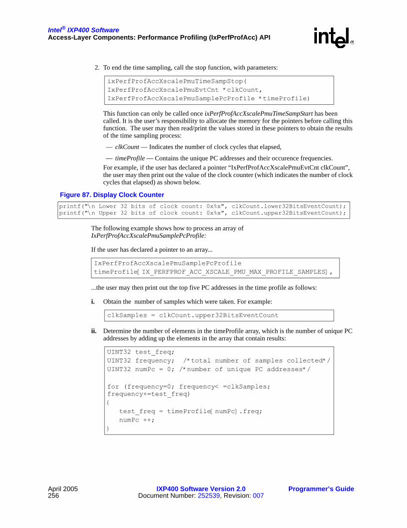
Intel® IXP400 SoftwareAccess-Layer Components: Performance Profiling (IxPerfProfAcc) API
April 2005 IXP400 Software Version 2.0 Programmer’s Guide256 Document Number: 252539, Revision: 007
2. To end the time sampling, call the stop function, with parameters:
This function can only be called once ixPerfProfAccXscalePmuTimeSampStart has been called. It is the user’s responsibility to allocate the memory for the pointers before calling this function. The user may then read/print the values stored in these pointers to obtain the results of the time sampling process:
— clkCount — Indicates the number of clock cycles that elapsed,
— timeProfile — Contains the unique PC addresses and their occurence frequencies.For example, if the user has declared a pointer “IxPerfProfAccXscalePmuEvtCnt clkCount”, the user may then print out the value of the clock counter (which indicates the number of clock cycles that elapsed) as shown below.
The following example shows how to process an array of IxPerfProfAccXscalePmuSamplePcProfile:
If the user has declared a pointer to an array...
...the user may then print out the top five PC addresses in the time profile as follows:
i. Obtain the number of samples which were taken. For example:
ii. Determine the number of elements in the timeProfile array, which is the number of unique PC addresses by adding up the elements in the array that contain results:
ixPerfProfAccXscalePmuTimeSampStop(IxPerfProfAccXscalePmuEvtCnt *clkCount,IxPerfProfAccXscalePmuSamplePcProfile *timeProfile)
Figure 87. Display Clock Counterprintf("\n Lower 32 bits of clock count: 0x%x", clkCount.lower32BitsEventCount);printf("\n Upper 32 bits of clock count: 0x%x", clkCount.upper32BitsEventCount);
IxPerfProfAccXscalePmuSamplePcProfile timeProfile[IX_PERFPROF_ACC_XSCALE_PMU_MAX_PROFILE_SAMPLES],
clkSamples = clkCount.upper32BitsEventCount
UINT32 test_freq;UINT32 frequency; /*total number of samples collected*/UINT32 numPc = 0; /*number of unique PC addresses*/
for (frequency=0; frequency< =clkSamples; frequency+=test_freq)
test_freq = timeProfile[numPc].freq;numPc ++;

Intel® IXP400 SoftwareAccess-Layer Components: Performance Profiling (IxPerfProfAcc) API
Programmer’s Guide IXP400 Software Version 2.0 April 2005Document Number: 252539, Revision: 007 257
iii. Print out the first five elements:
These profile results show the places in the user’s code that are most frequently being executed and that are taking up the most processor cycles.
The results for time sampling are also automatically written to a file when the “Stop” functions for these features are called. For vxWorks, this file is stored in the location pointed by the FTP server where the image for the system is downloaded from. In Linux, the file is stored in the /proc filesystem. As this filesystem is temporary, the user is required to copy the output file into a permanent location or else the results will be lost when a new round of sampling is done or when the system is stopped or rebooted. Sample file output for vxWorks is as follows:
Linux output is identical with the exception of the Percent column. In Linux, the user is also able to change the accuracy of matching the PC Address to the Symbol Address. The greater the accuracy required, the longer it takes to find a match. The recommended accuracy is 0xffff which means the module will reduce the PC Address by up to 0xffff until it can find a match. Else, a message is logged and “No symbol found” is written to the file. The accuracy can be changed by modifying the #define IX_PERFPROF_ACC_XSCALE_PMU_SYMBOL_ACCURACY.
The output filename is defined in IxPerfProfAcc. To use a different filename, the user is required to change the filename in the stop function for vxWorks or the ixPerfProfAccXscalePmuTimeSampCreateProcFile() function in Linux.
Note: The Linux proc file create API is declared public so that it can be called by the /proc file system. It should never be called directly by the user.
17.10.1.3 Event-Based Sampling
This utility can be used to profile the user’s code through event sampling. The process is similar to that of time sampling. However, this utility tells the user which lines of codes trigger occurrences of the events specified by the user. The sampling rate is defined by the user and is the number of events before a sample is taken. Each event defined, may have its own sampling rate.
for (i=0; i++; i<5)
printf("timeprofile element %d pc value = 0x%x\n", i, timeProfile[i].programCounter);printf("timeprofile element %d freq value = %d\n", i, timeProfile[i].freq);
Hits Percent PC Address Symbol Address Offset ClosestRoutine------- --------- ------------- ------------------ -------- -------------------
65451 99.8718 49a88 49914 174 reschedule14 0.0214 47938 47924 14 intUnlock10 0.0153 49a84 49914 170 reschedule10 0.0153 49a8c 49914 178 reschedule1 0.0015 54ab8 54ab8 0 __div32

Intel® IXP400 SoftwareAccess-Layer Components: Performance Profiling (IxPerfProfAcc) API
April 2005 IXP400 Software Version 2.0 Programmer’s Guide258 Document Number: 252539, Revision: 007
The steps needed to run this utility are:
1. To begin the event sampling, call the start function with parameters:
This function starts the event-based sampling to determine the frequency with which events are being executed. The sampling rate is the number of events, as specified by the user, before a counter overflow interrupt is generated.A sample is taken at each counter overflow interrupt. At each sample,the value of the program counter determines the corresponding location in the code. Each of these occurrences are recorded to determine the frequency with which the Intel XScale core’s code in each event is executed.This API has to be called before ixPerfProfAccXscalePmuEventSampStop can be called.
— UINT32 [in] <numEvents> — The number of PMU events that are to be monitored as specified by the user. The value should be between 1-4 events at a time.
— IxPerfProfAccXscalePmuEvent [in] pmuEvent1 — The specific PMU event to be monitored by counter 1
— UINT32 [in] eventRate1, eventRate2, eventRate3, eventRate4 — The number of events before a sample taken. If 0 is specified, the full counter value (0xFFFFFFFF) is used. The rate must not be greater than the full counter value.
2. To end the event sampling, call the stop function, with parameters:
It is the user’s responsibility to allocate the memory for the pointers before calling this function. The user may then read/print the values stored in these pointers to obtain the results of the event sampling process. The user may obtain the number of samples for each event counter by calling the function ixPerfProfAccXscalePmuResultsGet(). The results are presented to the calling function in a sorted form from the PC address with the highest frequency to the PC address with the lowest frequency of hits.
The event profiles will show the user the parts of the code that cause the specified events to occur.
The results for event sampling are also automatically written to a file when the “Stop” functions for these features are called. For vxWorks, this file is stored in the location pointed by the FTP server where the image for the system is downloaded from. In Linux, the file is stored in the /proc file system.
ixPerfProfAccXscalePmuEventSampStart(UINT32 numEvents, IxPerfProfAccXscalePmuEvent pmuEvent1, UINT32 eventRate1, IxPerfProfAccXscalePmuEvent pmuEvent2, UINT32 eventRate2, IxPerfProfAccXscalePmuEvent pmuEvent3, UINT32 eventRate3, IxPerfProfAccXscalePmuEvent pmuEvent4, UINT32 eventRate4)
ixPerfProfAccXscalePmuEventSampStop(IxPerfProfAccXscalePmuSamplePcProfile *eventProfile1,IxPerfProfAccXscalePmuSamplePcProfile *eventProfile2,IxPerfProfAccXscalePmuSamplePcProfile *eventProfile3,IxPerfProfAccXscalePmuSamplePcProfile *eventProfile4)

Intel® IXP400 SoftwareAccess-Layer Components: Performance Profiling (IxPerfProfAcc) API
Programmer’s Guide IXP400 Software Version 2.0 April 2005Document Number: 252539, Revision: 007 259
As this file system is temporary, the user is required to copy the output file into a permanent location or else the results will be lost when a new round of sampling is done or when the system is stopped or rebooted.
Sample file output for Linux is as follows:
VxWorks output is identical, but also includes a Percent column. In Linux, the user is also able to change the accuracy of matching the PC Address to the Symbol Address. The greater the accuracy required, the longer it takes to find a match. The recommended accuracy is 0xffff which means the module will reduce the PC Address by up to 0xffff until it can find a match. Else, a message is logged and “No symbol found” is written to the file. The accuracy can be changed by modifying the #define IX_PERFPROF_ACC_XSCALE_PMU_SYMBOL_ACCURACY.
The output filename is defined in IxPerfProfAcc. To use a different filename, the user is required to change the filename in the stop function for vxWorks or the ixPerfProfAccXscalePmuTimeSampCreateProcFile() function in Linux.
Note: The Linux proc file create API is declared public so that it can be called by the /proc file system. It should never be called directly by the user.
Total Number of Samples for Event1 = 0
Hits PC Address Symbol Address Offset Routine------- ---------- -------------- ------ -------------------
Total Number of Samples for Event2 = 0
Hits PC Address Symbol Address Offset Routine------- ---------- -------------- ------ -------------------
Total Number of Samples for Event3 = 65535
Hits PC Address Symbol Address Offset Routine------- ------------ ------------ ------ -------------------------------------------21814 c004dd38 c004dac4 274 schedule [Module - kernel]21381 c0058cac c0058c7c 30 add_timer [Module - kernel]21329 c00594a4 c005949c 8 schedule_timeout [Module - kernel]189 c0058c84 c0058c7c 8 add_timer [Module - kernel]124 c0059520 c005949c 84 schedule_timeout [Module - kernel]95 c00594a8 c005949c c schedule_timeout [Module - kernel]
Total Number of Samples for Event4 = 6
Hits PC Address Symbol Address Offset Routine----- ----------- ------- --------------- -------------------5 c004dd38 c004dac4 274 schedule [Module - kernel]1 c0112788 0 c0112788 No lower symbol found. [Module - kernel]

Intel® IXP400 SoftwareAccess-Layer Components: Performance Profiling (IxPerfProfAcc) API
April 2005 IXP400 Software Version 2.0 Programmer’s Guide260 Document Number: 252539, Revision: 007
17.10.1.4 Using Intel XScale® Core PMU to Determine Cache Efficiency
In this example, the user would like to monitor the instruction cache efficiency mode. The user would use the event counting process to count the total number of instructions that were executed and instruction cache misses requiring fetch requests to external memory.
The remaining two counters will not provide relevant results in this example. The counters may be set to the appropriate default event value.
1. To begin the counting, call the start function, with parameters:
2. Declare a results variable:
3. To end the counting, call the stop function, with parameters:
4. Print the total value (combining the upper and lower 32 bits) of all the counters:
Note: As only event counters one and two were configured to monitor events, the results of event counters 3 and 4 will remain at zero and will be irrelevant.
5. The appropriate statistics can be calculated from the results to determine the instruction cache efficiency. The instruction cache miss rate is the instruction cache misses (monitored by event counter two) divided by the total number of instructions executed (monitored by event counter one):Instruction cache miss rate
— =instruction cache misses/total number of instructions executed
— = total event count 2 / total event count 1
6. The average number of cycles it took to execute an instruction (also known as cycles-per-instruction), is the total clock count (monitored by the clock counter) divided by the total number of instructions executed (monitored by event counter 1):
ixPerfProfAccXscalePmuEventCounting (FALSE, 2,IX_PERFPROF_ACC_XSCALE_PMU_EVENT_INST_EXEC,IX_PERFPROF_ACC_XSCALE_PMU_EVENT_CACHE_MISS,IX_PERFPROF_ACC_XSCALE_PMU_EVENT_MAX,IX_PERFPROF_ACC_XSCALE_PMU_EVENT_MAX)
IxPerfProfAccXscalePmuResults results;
ixPerfProfAccXscalePmuEventCountStop (IxPerfProfAccXscalePmuResults &results)
printf(“total clk count = 0x%x%x\n”, results.clk_samples, results.clk_value);printf(“total event 1 count = 0x%x%x\n”, results.event1_samples, results.event1_value);printf(“total event 2 count = 0x%x%x\n”, results.event2_samples, results.event2_value);printf(“total event 3 count = 0x%x%x\n”, results.event3_samples, results.event3_value);printf(“total event 4 count = 0x%x%x\n”, results.event4_samples, results.event4_value);
cycles-per-instruction = total clock count / total number of instructions executed = total clk count / total event count 1

Intel® IXP400 SoftwareAccess-Layer Components: Performance Profiling (IxPerfProfAcc) API
Programmer’s Guide IXP400 Software Version 2.0 April 2005Document Number: 252539, Revision: 007 261
17.10.2 Internal Bus PMUThe Internal Bus PMU utility enables performance monitoring of components accessing or utilizing the north and south bus, provides statistics of the north and south bus and SDRAM, and allows the user to read the value of the Previous Master Slave Register.
The user may monitor their code/program in two ways:
• From the CLI, call the appropriate Internal Bus PMU utility
• In the user’s code itself, insert the appropriate Internal Bus PMU utility’s start and stop functions.
To run this utility:
1. Begin the measurements, call the start function with parameters:
This function initializes all the counters and assigns the events associated with the counters. Selecting HALT mode will generate error. User should use ixPerfProfAccBusPmuStop() to HALT.
2. To end the measurements, call the stop function, to stop all the counters:
3. If at any time before, during, or after the counting process, the user wishes to view the value of the counters, the user may call the following function, with parameter:
It is the user’s responsibility to allocate the memory for the pointer before calling this function. The user may then read/print the values stored in this pointer to obtain the results of the measurements.IxPerfProfAccBusPmuResults has two arrays:
— For the lower 27-bit of counter values —
— For upper 32 Bit of counter values. The user should be aware that in the lower 27-bit counter, it only stores values up to 27 bits before causing an overflow —
ixPerfProfAccBusPmuStart(IxPerfProfAccBusPmuMode mode, IxPerfProfAccBusPmuEventCounters1 pecEvent1,IxPerfProfAccBusPmuEventCounters2 pecEvent2, IxPerfProfAccBusPmuEventCounters3 pecEvent3, IxPerfProfAccBusPmuEventCounters4 pecEvent4,IxPerfProfAccBusPmuEventCounters5 pecEvent5, IxPerfProfAccBusPmuEventCounters6 pecEvent6, IxPerfProfAccBusPmuEventCounters7 pecEvent7)
ixPerfProfAccBusPmuStop()
ixPerfProfAccBusPmuResultsGet (IxPerfProfAccBusPmuResults *busPmuResults)
UINT32 statsToGetLower27Bit [IX_PERFPROF_ACC_BUS_PMU_MAX_PECS]
UINT32 statsToGetUpper32Bit [IX_PERFPROF_ACC_BUS_PMU_MAX_PECS]

Intel® IXP400 SoftwareAccess-Layer Components: Performance Profiling (IxPerfProfAcc) API
April 2005 IXP400 Software Version 2.0 Programmer’s Guide262 Document Number: 252539, Revision: 007
For example:
— If the user has declared a variable “IxPerfProfAccBusPmuResults busPmuResults,” the user may then print out the value of all seven of the PEC counters. The user should be aware that in the lower 27-bit counter, it only stores values up to 27 bits before causing an overflow. Therefore, in order to combine the lower 27-bit value with the upper, 32-bit value, the following calculations are done:
— If the user declares variables “UINT32 lower32Bits” and “UINT32 upper32Bits,” and assigns them to the values calculated above, the user may print out the results as follows:
This will print out the entire value of the PC in hexadecimal.
Note: For the ixPerfProfAccBusPmuPMSRGet() function, the user may refer to the codelet for a detailed description.
17.10.2.1 Using the Internal Bus PMU Utility to MonitorRead/Write Activity on the North Bus
In this example, the user would like to monitor the number of cycles where the north bus is either idle, or is being written to or read from. In order to do so, the user selects the north mode. PECs 1, 2, and 3 will be set to monitor the number of cycles the bus is doing data writes/reads or is idle. PEC 7 will be set to monitor the total number of cycles.
The remaining counters will not provide relevant results in this examples, therefore, they may be set to any appropriate north mode event.
1. To begin the measurements, call the start function with parameters:
2. After an appropriate amount of time, end the measurements by calling the stop function:
3. Declare a variable for the results:
lower32Bits = (lower 27-bit counter value) +[(upper 32-bit counter value) & 0x1F ) << 27 ]upper32Bits = (upper 32-bit counter value) >> 5Total PEC counter value = (upper32Bits<<32) |lower32Bits
for (i = 0; i< IX_PERFPROF_ACC_BUS_PMU_MAX_PECS ; i++) printf ("\n The value of PEC %d = 0x%8x%8x ", i, upper32Bits, lower32Bits);
ixPerfProfAccBusPmuStart (IX_PERFPROF_ACC_BUS_PMU_MODE_NORTH, IX_PERFPROF_ACC_BUS_PMU_PEC1_NORTH_BUS_IDLE_SELECT,IX_PERFPROF_ACC_BUS_PMU_PEC2_NORTH_BUS_WRITE_SELECT, IX_PERFPROF_ACC_BUS_PMU_PEC3_NORTH_BUS_READ_SELECT,
IX_PERFPROF_ACC_BUS_PMU_PEC4_NORTH_ABB_SPLIT_SELECT, IX_PERFPROF_ACC_BUS_PMU_PEC5_NORTH_PSMB_GRANT_SELECT, IX_PERFPROF_ACC_BUS_PMU_PEC6_NORTH_PSMC_GRANT_SELECT, IX_PERFPROF_ACC_BUS_PMU_PEC7_CYCLE_COUNT_SELECT)
ixPerfProfAccBusPmuStop(void)
IxPerfProfAccBusPmuResults results

Intel® IXP400 SoftwareAccess-Layer Components: Performance Profiling (IxPerfProfAcc) API
Programmer’s Guide IXP400 Software Version 2.0 April 2005Document Number: 252539, Revision: 007 263
4. Obtain the results by calling:
5. Print the value of all the PECs:
6. Print the total value of PECs 1-3, and PEC 7. The upper 32 bits reflect the number of times the lower 27-bit value overflowed:
7. Perform the same calculation for the rest of the PECs.
8. Determine the percentage of cycles that the bus was either idle or performing Data Writes/Reads:
17.10.3 Xcycle (Idlecycle Counter)The Xcycle utility calculates the cycles remaining compared with the cycles available during an idle period. The user may monitor the load of their program by obtaining the percentage of idle cycles available with their program running.
The user may monitor their code/program by creating a thread that runs the code being monitored. At the same time, on a separate thread, run the Xcycle utility.
To run this utility:
1. Before creating any other threads, perform calibration and obtain the baseline (i.e. the total available cycles in the period of time specified) when there is no load:
It is the user’s responsibility to allocate the memory for the pointer before calling this function. The user may then read/print this pointer to obtain the total available cycles when there is no load on the system.
ixPerfProfAccBusPmuResultsGet (&results)
for (i = 0; i< IX_PERFPROF_ACC_BUS_PMU_MAX_PECS ; i++)
printf ("\nPEC %d = upper 0x%x lower 0x%x ", i, results.statsToGetUpper32Bit[i], results.statsToGetLower27Bit[i]);
printf ("Total value of PEC1 0x%8x%8x", results.statsToGetUpper32Bit[0], results.statsToGetLower27Bit[0]);
PEC1_total = total value of north bus idle cyclesPEC2_total = total value of north bus data write cyclesPEC3_total = total value of north bus date read cyclesPEC7_total = total value of cycles available
Percentage of idle cycles = (PEC1_total /PEC7_total) *100%Percentage of data write cycles = (PEC2_total/PEC7_total) * 100%Percentage of date read cycles = (PEC3_total/PEC7_total) * 100%
ixPerfProfAccXcycleBaselineRun (UINT32 *numBaselineCycle)

Intel® IXP400 SoftwareAccess-Layer Components: Performance Profiling (IxPerfProfAcc) API
April 2005 IXP400 Software Version 2.0 Programmer’s Guide264 Document Number: 252539, Revision: 007
This pointer is interpreted as “the number of 66-MHz clock ticks for one measurement.” It is stored within the tool while it is being run and serves only as a reference for the user.
2. Create a thread that runs the code to be monitored. To begin the Xcycle measurements, call the start function, with parameter:
This start the measurements immediately. numMeasurementsRequested specifies number of measurements to run.If numMeasurementsRequested is set to 0, the measurement will be performed continuously until IxPerfProfAccXcycleStop() is called. It is estimated that one measurement takes approximately 1 s during low CPU utilization, therefore 128 measurement takes approximately 128 s.When CPU utilization is high, the measurement will take longer. This function spawn a task the perform the measurement and returns. The measurement may continue even if this function returns.There are only IX_PERFPROF_ACC_XCYCLE_MAX_NUM_OF_MEASUREMENTS storage available so storing is wrapped around if measurements are more than IX_PERFPROF_ACC_XCYCLE_MAX_NUM_OF_MEASUREMENTS.
3. If ixPerfProfAccXcycleStart() is called with an input of zero, this indicates continuous measurements. In this case, the measurements are stopped, by calling the stop function:
As it takes the measurements some time to complete, the user should call the following function to determine if any measurements are still running:
4. To obtain the results of the measurements made, the user should call the results function, with parameter:
The result contains:
— float maxIdlePercentage — Maximum percentage of Idle cycles
— float minIdlePercentage — Minimum percentage of Idle cycles
— float aveIdlePercentage — Average percentage of Idle cycles
— UINT32 totalMeasurements — Total number of measurement made If the user has declared a pointer IxPerfProfAccXcycleResults *xcycleResult, the user may then print out the results of the xcycle measurements as shown in Figure 88.
ixPerfProfAccXcycleStart(UINT32 numMeasurementsRequested)
ixPerfProfAccXcycleStop(void)
ixPerfProfAccXcycleInProgress(void)
ixPerfProfAccXcycleResultsGet(IxPerfProfAccXcycleResults *xcycleResult)
Figure 88. Display Xcycle Measurementprintf("Maximum percentage of idle cycles = %f\n", xcycleResult->maxIdlePercentage);
printf("Minimum percentage of idle cycles = %f\n", xcycleResult->minIdlePercentage);printf("Average percentage of idle cycles = %f\n", xcycleResult->aveIdlePercentage);printf("Total number of measurements = %u\n", xcycleResult->totalMeasurements);

Intel® IXP400 Software
Programmer’s Guide IXP400 Software Version 2.0 April 2005Document Number: 252539, Revision: 007 265
Access-Layer Components:Queue Manager (IxQMgr) API 18
This chapter describes the Intel® IXP400 Software v2.0’s “Queue Manager API” access-layer component.
18.1 What’s NewThere are no changes or enhancements to this component in software release 2.0.
18.2 OverviewThe IxQMgr (Queue Manager) access-layer component is a collection of software services responsible for configuring the Advanced High-Performance Bus (AHB) Queue Manager (also referred to by the combined acronym AQM). IxQMgr is also responsible for managing the flow of IX_OSAL_MBUF buffer pointers to and from the NPEs and client Intel XScale® Core software. To do this, the IxQMgr API provides a low-level interface to the AQM hardware block of the Intel® IXP4XX product line and IXC1100 control plane processors. Other access-layer components can then use IxQMgr to pass and receive data to and from the NPEs through the AQM.
This chapter presents the necessary steps to start the IxQMgr component. A high-level overview of AQM functions is also provided. The IxQMgr component acts as a pseudo service layer to other access-layer components such as IxEthAcc.
In the sections that describe how the Queue Manager works, the “client” is an access component such as IxEthAcc. Application programmers will only need to write code for the initialization and uninitialization of the IxQMgr component, not for directly controlling the queues and the AQM.

Intel® IXP400 SoftwareAccess-Layer Components: Queue Manager (IxQMgr) API
April 2005 IXP400 Software Version 2.0 Programmer’s Guide266 Document Number: 252539, Revision: 007
18.3 Features and Hardware Interface
The IxQMgr provides a low-level interface for configuring the AQM, which contains the physical block of static RAM where all the data structures (queues) for the IxQMgr reside. The AQM provides 64 independent queues in which messages, pointers, and data are contained. Each queue is configurable for buffer and entry size and is allocated a status register for indicating relative fullness.
The AQM maintains these queues as circular buffers in an internal, 8-Kbyte SRAM. Status flags are implemented for each queue. The status flags for the lower 32 queues are transmitted to the NPEs via the flag data bus. Two interrupts — (QM1) one for the lower 32 queues and (QM2) one for the upper 32 queues — are used as queue status interrupts.
The AHB interface provides for complete queue configuration, queue access, queue status access, interrupt configuration, and SRAM access.
IxQMgr provides the following services:
• Configures AQM hardware queues.Configuration of a queue includes queue size, entry size, watermark levels, and interrupt-source-select flag. IxQMgr checks the validity of the configuration parameters and rejects any configuration request that presents invalid parameters.
• Allows callbacks to be registered for each queue. This is also referred as notification callback.
• Enables and disables notifications for each queue.
• Sets the priority of a callback.
• Provides queue-notification source-flag select.
— For queues 0-31, the notification source is programmable as the assertion or de-assertion of one of four status flags: Empty, Nearly Empty, Nearly Full, and Full.
Figure 89. AQM Hardware Block
NPE
AHB
Flag Bus
AHB Queue Manager
QueueBufferSRAM
QueueControl
AHBSlave
Config/StatusRegisters
Int
Intel XScale® Core
B2415-02
Intel® IXP400 SoftwareAccess-Layer Components: Queue Manager (IxQMgr) API
Programmer’s Guide IXP400 Software Version 2.0 April 2005Document Number: 252539, Revision: 007 267
— For queues 32-63, the notification source is the assertion or de-assertion of the Nearly Empty flag and cannot be changed.
• Performs queue-status query.
— For queues 0-31, the status consists of the flags Nearly Empty, Empty, Nearly Full, and Full, Underflow and Overflow.
— For queues 32-63, the status consists of the flags Nearly Empty and Full.
• Determines the number of full entries in a queue.
• Determines the size of a queue in entries.
• Reads and writes entries from/to AQM.
• Dispatches queue notification callbacks registered by clients. These are called in a defined order, based on a set of conditions.
18.4 IxQMgr Initialization and UninitializationThe initialization of IxQMgr first requires a call to ixQMgrInit(), which takes no parameters and returns success or failure. No other ixQMgr functions may be called before this. Following initialization, the queues must be configured, and the dispatcher function should be called. Only one dispatcher can be invoked per each set of upper and lower 32 queues.
To uninitialize the IxQMgr component, call the ixQMgrUnload() function, which also takes no parameters and returns success or failure. Uninitialization should be done prior to unloading components that are dependant on IxQMgr. Uninitialization will unmap kernel memory mapped by the component. As an example, uninitialization should be done before unloading a kernel module or (if possible) before a soft reset.
To avoid unpredictable results, the ixQMgrUnload function should not be called twice in sequence before a call to ixQMgrInit. No other ixQMgr functions may be called after ixQMgrUnload except for ixQMgrInit.
18.5 Queue ConfigurationThe queue base address in AQM SRAM is calculated at run time. The IxQMgr access-layer component must be initialized by calling ixQMgrInit() before any queue is configured. Queue configurations include queue size, queue entry size, queue watermarks, interrupt enable/disable and callback registration. A check is performed on the queue configuration to ensure that the amount of SRAM required by the configuration does not exceed the amount available. The Queue configuration function ixQMgrQConfig( ) provides a configuration interface to the AQM queues. With the exception of ixQMgrQWatermarkSet(), the queue-configuration information to which this interface provides access can only be set once.
18.6 Queue IdentifiersAn AQM hardware queue is identified by one of the 64 unique identifiers. Each IxQMgr interface function that operates on a queue takes one of the 64 identifiers (defined in IxQMgr.h) as a parameter and it is the clients responsibility to provide the correct identifier.

Intel® IXP400 SoftwareAccess-Layer Components: Queue Manager (IxQMgr) API
April 2005 IXP400 Software Version 2.0 Programmer’s Guide268 Document Number: 252539, Revision: 007
18.7 Configuration ValuesTable 48 details the attributes of a queue that can be configured and the possible values that these attributes can have (word = 32 bits).
18.8 Dispatcher The IxQMgr access-layer component provides a dispatcher to enable clients to register notification callbacks to be called when a queue is in a specified state. A queue’s state is defined by the queue status flags E, NE, NF, F, NOTE, NOTNE, NOTNF, and NOTF. Each queue will have its own watermark level defined, which triggers a change in its status flag and generates an interrupt to the Intel XScale core. The QM1 Queue Manager interrupt to the Intel XScale core represents a change in the queue status for lower queues 0-31, and the QM2 interrupt represents a change in the queue status for upper queues 32-63.
In case of the upper queues 32-63, the notification occurs on change of the Nearly Empty flag and the watermark levels cannot be changed. The watermark level triggers the change of the status flag for a particular queue, and the upper queues 0-31 provide additional control when the interrupt gets triggered.
Prior to start of the dispatcher, ixQMgrDispatcherLoopGet( ) is used to get a pointer to the correct queue dispatcher. The function pointer being returned in response to ixQMgrDispatcherLoopGet( ) is — in the remainder of this section — referred to as the “dispatcher”. There are three dispatchers in the IxQMgr component that may be returned to ixQMgrDispatcherLoopGet().
• ixQMgrDispatcherLoopRunA0 - This dispatcher is called when an IXP42X product line A-0 stepping processor is detected.
• ixQMgrDispatcherLoopRunB0 - This is the default dispatcher for IXP42X product line B-0 stepping and all IXP46X product line processors are detected.
• ixQMgrDispatcherLoopRunB0LLP - This dispatcher is a variation of the ixQMgrDispatcherLoopRunB0 dispatcher that adds LiveLock Prevention support (refer to “Livelock Prevention” on page 272). The IxFeatureCtrl component is used to select whether this dispatcher is to be selected or not, as described in Section 12.5.
There is no assumption made about how the dispatcher is called. For example, ixQMgrDispatcherLoopRunA0(), ixQMgrDispatcherLoopRunB0( ) or ixQMgrDispatcherLoopRunB0LLP( ) may be registered as an ISR for the AQM interrupts, or it
Table 48. AQM Configuration Attributes
Attribute Description Values
Queue Size
The maximum number of words that the queue can contain.Equals the number of entries x queue entry size (in words).
16, 32, 64, or 128 words
Queue Entry Size The number of words in a queue entry. 1, 2, or 4 words
NE Watermark The maximum number of occupied entries for which a queue is considered nearly empty.
0, 1, 2, 4, 8, 16, 32, or 64 entries
NF Watermark The maximum number of empty entries for which a queue is considered to be nearly full.
0, 1, 2, 4, 8, 16, 32, or 64 entries

Intel® IXP400 SoftwareAccess-Layer Components: Queue Manager (IxQMgr) API
Programmer’s Guide IXP400 Software Version 2.0 April 2005Document Number: 252539, Revision: 007 269
may be called from a client polling mechanism, which calls the dispatcher to read the queues status at regular intervals. In the first example, the dispatcher is called in the context of an interrupt and the dispatcher gets invoked when the queue status change.
A parameter passed to the ixQMgrDispatcherLoopRun() function determines whether the lower set of 32 queues, queues 0-31 or the upper set of 32 queues, queue 32-63 are serviced by the dispatcher each time ixQMgrDispatcherLoopRun() is called. The order in which queues are serviced depends on the priority specified by calling ixQMgrQDispatchPrioritySet().
Note: Application software does not need to access the queues directly. The underlying access-layer component software (for example, EthAcc, HssAcc, etc.) handles this. However, the application software does need to initialize the queue manager software using ixQmgrInit and set up the dispatcher operation.
18.9 Dispatcher ModesThe Codelet/Customer code must first initialize the IxQMgr by making a call to ixQMgrInit(), which takes no parameters and returns success or failure. No other IxQMgr functions may be called by other access-layer components before this. After initialization, the queues must be configured before they can be used.
Note: The ixQMgrInit() function should only be called once for a system. Once the IxQMgr has been started all other access-layer components can register to use the services it provides without calling ixQMgrInit().
The access-layer provides the following services for the application by performing the following functions:
— Perform Queue configuration
— Set the watermark levels
— Reads and writes entries to and from AQM
— Provides register-notification callbacks for a queue
— Set the priority of a dispatcher callback
Once the IxQMgr is initialized, the access component configures the queues. Queue configuration is done by setting up the attributes for respective queues. These attributes are typically set in the access components by using ixQMgrQConfig( ) and ixQMgrWatermarkSet( ) functions. Depending upon whether the queue is half full, nearly full, etc., the watermark level triggers the change of the status flag for a particular queue. The queue configuration and setting of the watermark levels and queue priority should be performed prior to enabling of the queue notification status flag. Once the queues are configured, the notification callback needs to be set or else it will go to a dummy callback. The Queue dispatcher loop can be started at any time following a ixQMgrInit(). However, the dispatcher function will service the callback only once the queue notification is enabled.
The IxQMgr governs the flow of traffic in Intel® IXP400 Software. Depending upon the OS, the application, and the performance required, there are three different ways the dispatcher can be called: Busy loop, event-, or timer-based interrupt. The dispatcher can be called either in context of an interrupt or through a busy loop (which might run as a low-priority task). In case of an interrupt-driven mechanism, the interrupt can be triggered either by a timer or upon generation of QM hardware interrupts (which are event-driven). There is no single way to determine the best

Intel® IXP400 SoftwareAccess-Layer Components: Queue Manager (IxQMgr) API
April 2005 IXP400 Software Version 2.0 Programmer’s Guide270 Document Number: 252539, Revision: 007
mechanism, although the choice of implementation would depend upon the OS, the application, and the nature of the traffic. The following includes factors to be considered in selecting the appropriate mechanism:
• Event-based interrupt – Interrupt driven through QM1 or QM2 interrupt:
— system is interrupted only when there is traffic to service
— suitable for low traffic rates
— provides lowest latency
• Timer-based interrupt – polled from timer-based interrupt:
— suitable for high traffic rates
— minimizes the ISR overhead
— most efficient use of the Intel XScale core
• Polling mode – Busy loop to poll the queues:
— suitable for higher traffic rates
— throttles traffic automatically when additional cycles are not available on the Intel XScale core
The status flag gets cleared within the dispatcher loop prior to servicing of the callback function. The QM1 and QM2 interrupt gets cleared when all the status flags for all the queues are cleared and if the interrupt enable bit is set. There can only be one dispatcher loop that can be defined for each set of queues.
Once the IxQMgr is initialized and the queues are configured, the Codelet/Customer code must determine how to invoke the dispatcher. Prior to invoking the dispatcher function, as stated before, the ixQMgrDispatcherLoopGet(&dispatcher), returns a function pointer for the appropriate dispatcher. The dispatcher is invoked with an argument that points to the upper or lower 32 queues to determine if any queues in that group require servicing.
Note: Only one dispatcher can be invoked per each set of upper and lower 32 queues. The client can register multiple callbacks as long as each of the callbacks are for different queues. When interrupted, the dispatcher will read the status flag register from the AQM and service only one of the callbacks that was registered for a given queue. In the event that multiple callbacks are registered for the same queue, the dispatcher will service the last registered callback.
Figure 90 shows the following sequence of events that occur when a dispatcher is run in the context of an interrupt.
At the start of the dispatcher, the interrupt register is read and written back immediately except in case of a livelock dispatcher. Since livelock prevention uses sticky interrupt, the interrupt gets cleared only when the queue threshold falls below the set watermark level.
1. The user registers a callback function with the access-layer component (for example, EthAcc). The dispatcher invokes callback in the access-layer component, and the access-layer component then invokes the user callback.
2. When the NPE receives a packet it updates the Rx Queue with location of the buffer.
3. Provided the Interrupt bit is set, when the water mark is crossed the status flag gets updated corresponding to that queue and it triggers an interrupt to the Intel XScale core.
4. The Intel XScale core vectors the interrupt to the corresponding ISR.

Intel® IXP400 SoftwareAccess-Layer Components: Queue Manager (IxQMgr) API
Programmer’s Guide IXP400 Software Version 2.0 April 2005Document Number: 252539, Revision: 007 271
5. The ISR invokes the dispatcher.
Note: In the context of an interrupt, the dispatcher can also be invoked through a timer-based mechanism.
6. The IxQMgr reads the status flag.
7. The IxQMgr access-layer component calls the registered notification.
8. The client gets the buffer pointer on the Rx queue from the access-layer through the callback. The access-layer, in turn, accesses the Rx queue through the IxQMgr access-layer component. The IxQMgr accesses the AQM hardware.
Following this, the Intel XScale core may allocate a free buffer from the memory pool to the RxFree queue for the next incoming packet from the NPE.
Figure 91 shows the sequence of events that occurs when a dispatcher is ran in the context of a polling mechanism.
At the start of the dispatcher a call is made to read the status of the status flag to check if the queue watermark threshold has been crossed. It then immediately clears the status flag. In case of livelock prevention feature, the status flag is not cleared immediately because of the sticky interrupt implementation.
1. The user registers a callback function with the access-layer component (for example, EthAcc). The dispatcher invokes callback in the access-layer component, and the access-layer component then invokes the user callback.
Figure 90. Dispatcher in Context of an Interrupt
Low Group High Group
0 31 32 63
AQM
Interrupt High to Intel XScale® Core
Queue Status Bus to NPEs
Interrupt Low to Intel XScale® Core
NPE
2
3
ISR in OS (or) Timer
QMgr Component
Access-layer
Component
4
5
6Get Queue-Status
User Callback
1
StatusFlags
7
Register callback
Hardware
StatusFlags
8 Get the Queue
Intel XScale®
Core InterruptController
B3805 01

Intel® IXP400 SoftwareAccess-Layer Components: Queue Manager (IxQMgr) API
April 2005 IXP400 Software Version 2.0 Programmer’s Guide272 Document Number: 252539, Revision: 007
2. When the NPE receives a packet, it updates the Rx queue with location of the buffer.
3. When the watermark is crossed the status flag gets updated corresponding to that queue.
4. The polling thread calls the dispatcher.
5. The dispatcher loop gets the status of the updated flag and resets it.
6. The dispatcher invokes the registered access component.
7. The access-layer components re-routes the call back to the client and the client gets the buffer pointer through the callback on the Rx queue through the access-layer.
Following this, the Intel XScale core may allocate a free buffer from the memory pool to the RxFree queue for the next incoming packet from the NPE.
18.10 Livelock PreventionLivelock occurs when a task cannot finish in an expected time due to it being interrupted. The livelock prevention feature allows the critical task as in case of voice processing, being serviced by a particular queue, to run for a given set of time without it being interrupted in event of a system overload. For this to happen, a periodic queue is assigned to the critical task. Periodic queues are defined as queues which generate an interrupt at a regular interval leading to a task that runs for a set length of time (periodic task). Sporadic queues are queues that can generate an interrupt at any time. Livelock prevention is used to ensure that a periodic task is not interrupted by servicing for queues set as sporadic. This is achieved by disabling notifications for sporadic queues while the periodic task is running. When the periodic task is completed the sporadic queues have their notifications re-enable. Any servicing required for sporadic queues will occur at this time.
Figure 91. Dispatcher in Context of a Polling Mechanism
B3804-01
Low Group High Group
0 31 32 63
AQMQueue Status Bus to NPEs
NPE
2
Qmgr Component
AccessComponent
5Get Queue-Status
User Callback
1
StatusFlags
6
Register callback
Hardware
User Pollthread
4
3
Get the Queue 7

Intel® IXP400 SoftwareAccess-Layer Components: Queue Manager (IxQMgr) API
Programmer’s Guide IXP400 Software Version 2.0 April 2005Document Number: 252539, Revision: 007 273
To use livelock prevention, only one queue can be set as type periodic. One or more queues may be set as type sporadic using the ixQMgrCallbackTypeSet() function. By default, all the other queues that are not set to be in either a periodic or a sporadic mode are set in IX_QMGR_TYPE_REALTIME_OTHER mode. The IX_QMGR_TYPE_REALTIME_OTHER represents the default behavior of the callback function associated with respective queues when the livelock prevention feature is not in use. In a Livelock implimentation, these “other” queues will not have their interrupts disabled during the servicing of the periodic queue.
The ixQMgrCallbackTypeSet() function should be used to assign IX_QMGR_TYPE_REALTIME_PERIODIC to one queue and IX_QMGR_TYPE_REALTIME_SPORADIC to queue(s) by passing a Queue-ID along with the desired queue type.
Livelock prevention is disabled by default. In order to enable the livelock option the IX_FEATURECTRL_ORIGB0_DISPATCHER must be disabled using the ixFeatureCtrlSwConfigurationWrite() function before the ixQMgrInit() and ixQMgrDispatcherLoopGet() functions are called.
Queue assignments are located at ixp400_xscale_sw\src\include\IxQueueAssignments.h. If Ethernet QoS features are used, the Rx Priority queues are assigned in ixp400_xscale_sw\src\include\IxEthDBQoS.h. Queue type assignments may be checked with the ixQMgrCallbackTypeGet() function.
When ixQMgrDispatcherLoopRunB0LLP() reads the interrupt register and sees that a periodic queue is to be serviced, all queues that are set to be sporadic have their notification disabled. This prevents sporadic queues from generating interrupts, which may stall a task resulting from the periodic queue callback (periodic task). The ixQMgrPeriodicDone() function should be called after the periodic task is completed to ensure that sporadic queues are re-enabled.
Note: Because livelock prevention enables and disables notifications for queues set as sporadic, users should not enable and disable sporadic queues notifications other than at startup / shutdown.
Note: Livelock prevention operates on lower interrupt register queues only. (lower queue group 0-31).
Note: The Livelock dispatcher does not work on A-0 stepping versions of the IXP42X product line.
The following is an example sequence to show how livelock would be used is to set the HSS queue to periodic and the Eth Rx queue to sporadic using the ixQMgrCallbackTypeSet() function. When codec processing (the periodic task) as a result of a HSS callback is finished, the ixQMgrPeriodicDone() function is called and Eth Rx is then serviced. This will ensure that any codec processing that is done as a result of HSS notifications is not interrupted by a burst in Eth Rx.
• Use ixFeatureCtrlSwConfigurationWrite() to disable IX_FEATURECTRL_ORIGB0_DISPATCHER.
• Initialize the Queue Manager by using ixQMgrInit( ).
• Make a call to ixQMgrDispatcherLoopGet() to get the appropriate dispatcher function for livelock functionality.
• Initialize access-layer components, register the callback functions.

Intel® IXP400 SoftwareAccess-Layer Components: Queue Manager (IxQMgr) API
April 2005 IXP400 Software Version 2.0 Programmer’s Guide274 Document Number: 252539, Revision: 007
• Set the callback type for the HSS queue to periodic and the Eth Rx queue to sporadic using the ixQMgrCallbackTypeSet() function.
Note: All other queues (Tx queues, RxFree queues and TxDone queues) will have the callback type set to the default callback type of IX_QMGR_TYPE_REALTIME_OTHER.
• Start the dispatcher by calling the ixQMgrDispatcherLoop function.
• On completion of the periodic task, make a call to the ixQMgrPeriodicDone() function to enable the sporadic task.
18.11 ThreadingThe IxQMgr does not perform any locking on accesses to the IxQMgr registers and queues. If multiple threads access the IxQMgr, the following IxQMgr functions need to be protected by locking during concurrent access to the same queue:
• ixQMgrQWrite()
• ixQMgQRead()
• ixQMgrQReadWithChecks()
• ixQMgrQWriteWithChecks()
• ixMgrQBurstRead()
• ixQMgrQBurstWrite()
• ixQMgrQReadMWordsMinus1()
• ixQMgrQPeek()
• ixQMgrQPoke()
• ixQMgrQNotificationtEnable()
• ixQMgrQNotificationDisable()
• ixQMgrQStatusGet()
• ixQMgrQWatermarkSet()
• ixQMgrDispatcherLoopRunA0/B0/B0LLP()()
All IxQMgr functions can be called from any thread, with the exception of ixQMgrInit(), which should be called only once — before any other call.
18.12 DependenciesThe IxQMgr component is dependent on the OSAL and Feature Control components. IxQMgr uses OSAL to register AQM ISRs. IxQMgr also uses IxFeatureCtrl to determine the processor type and stepping to select which dispatchers may be supported.

Intel® IXP400 Software
Programmer’s Guide IXP400 Software Version 2.0 April 2005Document Number: 252539, Revision: 007 275
Access-Layer Components:Synchronous Serial Port (IxSspAcc) API 19
This chapter describes the Intel® IXP400 Software v2.0’s “SSP Serial Port (IxSspAcc) API” access-layer component.
19.1 What’s NewThis is a new component for software release 2.0.
19.2 IntroductionA Synchronous Serial Port is included in the Intel® IXP46X Product Line of Network Processors. The IxSspAcc API is provided to allow the configuration of the various registers related to the SSP hardware. Once configured, the API also provides the ability to transfer data to the Tx FIFO and from the Rx FIFO. Both polling and interrupt modes are supported.
19.3 IxSspAcc API Details
19.3.1 FeaturesThis component provides capabilities to:
• select frame format – SSP, SPI, or Microwire*
• select data sizes – 4 to 16 bits
• select clock source – external or on-chip
• configure serial clock rate – to drive a baud rate of 7.2 Kbps to 1.8432 Mbps (if internal clock source is selected only)
• enable/disable the receive FIFO level interrupts
• enable/disable the transmit FIFO level interrupts
• set the transmit FIFO threshold – 1 to 16 frames
• set the receive FIFO threshold – 1 to 16 frames
• select operation mode – normal or loop-back operation
• select SPI SCLK polarity – polarity of SCLK idle state is low or high (only used in SPI format)

Intel® IXP400 SoftwareAccess-Layer Components: Synchronous Serial Port (IxSspAcc) API
April 2005 IXP400 Software Version 2.0 Programmer’s Guide276 Document Number: 252539, Revision: 007
• select SPI SCLK phase – phase of SCLK starts with one inactive cycle and ends with ½ inactive cycle or SCLK starts with ½ inactive cycle and ends with one inactive cycle (only used in SPI format)
• select Microwire control word format – 8 or 16 bits
• enable/disable the SSP serial port hardware
This component also provides status and statistics for:
• SSP state – busy or idle
• Transmit FIFO level – 0 to 16 frames
• Receive FIFO level – 0 to 16 frames
• Transmit FIFO hit or below its threshold
• Receive FIFO hit or exceeded its threshold
• Receive FIFO overrun.
• Statistics for frames received, frames transmitted, and number of overrun occurrences.
19.3.2 DependenciesIxSspAcc is dependent on the capability provided by the SSP serial port hardware. IxOSAL provides OS independency.
Figure 92. IxSspAcc Dependencies
B4388-01
Access-Layer Interface
Hardware Interface
Client Application
IxOSALIxSspAcc
SSP Port

Intel® IXP400 SoftwareAccess-Layer Components: Synchronous Serial Port (IxSspAcc) API
Programmer’s Guide IXP400 Software Version 2.0 April 2005Document Number: 252539, Revision: 007 277
19.4 IxSspAcc API Usage Models
19.4.1 Initialization and General Data ModelThis description assumes a single client model where there is a single application-level program configuring the SSP interface and initiating I/O operations.
The client must first define the initial configuration of the SSP port by storing a number of values in the IxSspInitVars structure. The values include the frame format, input clock source, clock frequency, threshhold values for the FIFOs, pointers to callback functions for various data scenarios, and other configuration items. After the structure is defined, ixSspAccInit() may be called to enable the port.
Once the port is enabled, the client will use one of the data models described later in this chapter (either Interrupt or Polling mode) to determine how and when data I/O operations need to occur. A handler (or callback) is registered for transmit and receive operations. These handlers will use the ixSspAccFIFODataSubmit() and ixSspAccFIFODataReceive() functions for transmitting and receiving data.
After the SSP port has been initialized as described above, the SSP port may be re-configured. Most of the port configuration options may be modified via available functions in the API. For example, the frame format may be changed from SPI to Microwire.
The API also provides functions to disable the SSP port, check for port activity, maintains statistics for transmitted frames, received frames and overruns, and has other debugging type functions.
19.4.2 Interrupt ModeThe sequence flow for a client application using this component in interrupt mode is described below. Refer to Figure 93.
1. Initialize the SSP interface with interrupts enabled.
2. For receive operations:
a. Interrupt is triggered due to hitting or below of threshold.
b. If due to Rx FIFO, Rx FIFO handler/callback is called.
c. Rx FIFO handler/callback extracts data from the Rx FIFO.
d. (handler/callback processes the extracted data)
e. Rx FIFO handler/callback returns.
f. Interrupt is cleared.
3. For transmit operations:
a. Interrupt is triggered due to hitting or exceeding of threshold.
b. If due to Tx FIFO, Tx FIFO handler/callback is called.
c. Tx FIFO handler/callback inserts data into the Tx FIFO.
d. Tx FIFO handler/callback returns.
e. Interrupt is cleared.

Intel® IXP400 SoftwareAccess-Layer Components: Synchronous Serial Port (IxSspAcc) API
April 2005 IXP400 Software Version 2.0 Programmer’s Guide278 Document Number: 252539, Revision: 007
4. For an overrun:
a. Interrupt is triggered due to an overrun of the Rx FIFO.
b. Rx FIFO Overrun handler/callback is called.
c. Rx FIFO Overrun handler/callback extracts data from the Rx FIFO to prevent the overrun from triggering again.
d. (processes data extracted and perform necessary steps to recover data loss if possible)
e. Rx FIFO Overrun handler/callback returns.
f. Interrupt is cleared

Intel® IXP400 SoftwareAccess-Layer Components: Synchronous Serial Port (IxSspAcc) API
Programmer’s Guide IXP400 Software Version 2.0 April 2005Document Number: 252539, Revision: 007 279
Figure 93. Interrupt Scenario
B4389-01
Client SspAcc
ixSspAccInit : return
hardware
ixSspAccInit
interrupt: RxFIFOHitOrAboveThreshold
ixSspAccFIFODataReceive
Rx
hand
ler
ixSspAccFIFODataReceive: return
Data processing
RxFIFOIntrHandler
RxFIFOIntrHandler: return
interrupt: clear RxFIFOHitOrAboveThreshold
interrupt: TxFIFOHitOrBelowThreshold
TxFIFOIntrHandler
ixSspAccFIFODataSubmit
ixSspAccFIFODataSubmit: return
TxFIFOIntrHandler: return
interrupt: clear TxFIFOHitOrBelowThreshold
Tx h
andl
erin
itR
x FI
FO O
verr
un h
andl
er
interrupt: RxFIFOOverrun
ixSspAccFIFODataReceive
ixSspAccFIFODataReceive: return
Data processing/loss data recovery
RxFIFOOverrunHandler
RxFIFOOverrunHandler: return
interrupt: clear RxFIFOOverrun

Intel® IXP400 SoftwareAccess-Layer Components: Synchronous Serial Port (IxSspAcc) API
April 2005 IXP400 Software Version 2.0 Programmer’s Guide280 Document Number: 252539, Revision: 007
19.4.3 Polling ModeThe sequence flow for a client application using this component in polling mode is described below. Refer to Figure 94.
1. Initialize the SSP with interrupts disabled.
2. For transmit operations:
a. Check if the Tx FIFO has hit or is below its threshold.
b. If it has, then insert data into the Tx FIFO.
3. For receive operations:
a. Check if the Rx FIFO has hit or exceeded its threshold.
b. If it has, then extract data from the Rx FIFO.
c. Process the data if needed.
4. For an overrun:
a. Check if the Rx FIFO Overrun has occurred.
b. If it has, then extract data from the Rx FIFO.
c. Process the data and recover any lost data if needed.

Intel® IXP400 SoftwareAccess-Layer Components: Synchronous Serial Port (IxSspAcc) API
Programmer’s Guide IXP400 Software Version 2.0 April 2005Document Number: 252539, Revision: 007 281
Figure 94. Polling Scenario
B4390-01
Client SspAcc
ixSspAccInit : return
ixSspAccInit
ixSspAccFIFODataReceive
ixSspAccFIFODataReceive: return
Data processing
ixSspAccFIFODataSubmit
ixSspAccFIFODataSubmit: return
init
ixSspAccTxFIFOHitOrBelowThresholdCheck
ixSspAccTxFIFOHitOrBelowThresholdCheck: return
ixSspAccRxFIFOHitOrAboveThresholdCheck
ixSspAccRxFIFOHitOrAboveThresholdCheck: return
trans
mit
rece
ive
ixSspAccFIFODataReceive
ixSspAccFIFODataReceive: return
Data processing/ data loss recovery
ixSspAccRxFIFOOverrunCheck
ixSspAccRxFIFOOverrunCheck: return
Rx
FIFO
ove
rrun

This page is intentionally left blank.
Intel® IXP400 Software
April 2005 IXP400 Software Version 2.0 Programmer’s Guide282 Document Number: 252539, Revision: 007

Intel® IXP400 Software
Programmer’s Guide IXP400 Software Version 2.0 April 2005Document Number: 252539, Revision: 007 283
Access-Layer Components:Time Sync (IxTimeSyncAcc) API 20
This chapter describes the Intel® IXP400 Software v2.0’s “Time Sync (IxTimeSyncAcc) API” access-layer component.
The IxTimeSyncAcc access-layer component enables a client application, which implements the IEEE 1588* Precision Time Protocol (PTP) to configure the IEEE 1588 Hardware Assist block on the Intel® IXP46X Product Line of Network Processors.
20.1 What’s NewThis is a new component for software release 2.0.
20.2 IntroductionThe IEEE 1588 Precision Time Protocol (PTP) is used to synchronize independent clocks running in distributed network elements/nodes to a high degree of accuracy, in the microsecond to sub-microsecond range. There are three main elements involved in supporting IEEE 1588 on the IXP46X network processors:
• IEEE 1588 Hardware Assist block, available on the IXP46X network processors. The hardware provides necessary features to allow timestamping of the IEEE 1588 PTP messages.
• IxTimeSyncAcc Access-Layer component, running on the Intel XScale® Core. This software component provides the functionality required to enable the IEEE 1588 Hardware Assist block on various MII ports, set and receive timestamps, receive and transfer interrupt requests to client applications, and other functions.
• A IEEE 1588 PTP client application that would use the other two components to implement and use PTP messages and timestamps according to the IEEE 1588 specifications. Note: This client application is not provided as part of the IXP400 software.
These three elements are depicted in Figure 95.

Intel® IXP400 SoftwareAccess-Layer Components: Time Sync (IxTimeSyncAcc) API
April 2005 IXP400 Software Version 2.0 Programmer’s Guide284 Document Number: 252539, Revision: 007
20.2.1 IEEE 1588 PTP Protocol OverviewAs mentioned at the beginning of this chapter, the IEEE 1588 Precision Time Protocol (PTP) is used to synchronize independent clocks running in distributed network elements/nodes to a high degree of accuracy (in the nanosecond to sub-microsecond range). This section provides a very brief overview of the IEEE 1588 specification elements that relate to this IEEE 1588 hardware and software subsystem. For a more complete understanding of IEEE 1588, refer to IEEE Std 1588 -2002, IEEE Standard for a Precision Clock Synchronization Protocol for Networked Measurement and Control Systems, November 8, 2002 (available at http://ieee1588.nist.gov/).
The PTP protocol defines four timing-related messages: Sync, Delay_Req, Follow_Up and Delay_Resp. Furthermore, the protocol identifies a network element/node as either a master or a slave. The sequence and usage of the protocol messages vary depending on whether the node is configured in slave or master mode. Components within the PTP messages, such as the UUID and Sequence ID fields, are used by the master and slave elements/nodes to identify themselves and relate the sequence in which the PTP messages are exchanged.
Synchronization Sequence
The master provides the clock source to which all the slave nodes synchronize.
The master sends a Sync message to the slave node, carrying in it the master node’s system time as a timestamp. The master may also use Follow_Up message with the timestamp of the last Sync message to provide more accurate timestamp details to a slave, after accounting for the PHY,
Figure 95. IxTimeSyncAcc Component Dependencies
B4392-01
Access-Layer Interface
Hardware Interface
Client Application(1588 Protocol)
IxOSAL
IxTimeSyncAcc IxFeatureCtrl
IEEE 1588
Black Solid Arrow - Client Invocation PathBlack Dotted Arrow - Interrupt Invocation PathBlue Dotted Arrow - Interface with dependent components
Internal
External

Intel® IXP400 SoftwareAccess-Layer Components: Time Sync (IxTimeSyncAcc) API
Programmer’s Guide IXP400 Software Version 2.0 April 2005Document Number: 252539, Revision: 007 285
synchronization, and internal processing delays. The slave element/node, after detecting the Sync or Follow_Up message, will begin the process to synchronize its system clock based on the master clock timestamp.
The slave may also initiate an synchronization request by sending a Delay_Req message with its local system time as the timestamp to the master. The master will then respond with Delay_Resp, carrying both the timestamp at which the Delay_Req was received and the timestamp included by the slave in the Delay_Req message. This allows the slave to determine the transit delay and accordingly to update its system time.
20.2.2 IEEE 1588 Hardware Assist BlockOverview
The hardware provides necessary features to allow timestamping of the IEEE 1588 PTP messages. The IEEE 1588 Hardware Assist block internally snoops the MII interfaces that extend from the NPE components on the processor to Ethernet PHYs populated on the development or customer board. This provides the IEEE 1588 Hardware Assist block with the capability to detect the transversal of PTP protocol messages between the PHY and the MAC, and set internal timestamp registers with the appropriate data from these messages. When the timestamps of inbound or outbound messages are read by the hardware, the hardware block stores this information in a register.
The IEEE 1588 Hardware Assist block maintains a system time, which can be adjusted via API by the client application. Additionally, the block can be configured to interrupt the client application if the system time exceeds a specified target value.
Although IEEE 1588 PTP can be used for time synchronization of network elements/nodes over various communication media, this IEEE 1588 Hardware Assist block is designed to detect PTP messages over the NPE Ethernet interfaces only (not over the PCI interface).

Intel® IXP400 SoftwareAccess-Layer Components: Time Sync (IxTimeSyncAcc) API
April 2005 IXP400 Software Version 2.0 Programmer’s Guide286 Document Number: 252539, Revision: 007
Figure 96 shows the location of the IEEE 1588 Hardware Assist block and its main interconnects to other components in the IXP46X network processors.
Detailed Information
The IEEE 1588 Hardware Assist block implements a 64-bit register to keep track of the system time, which is used to provide timestamp references for PTP messages. The register is incremented based on a frequency scaling value, as supplied by the client application. The frequency scaling value is accumulated on every clock cycle in the system into a 32-bit register, and an overflow condition will cause the system time to increment. Thus, the slave will make use of the system time to synchronize with that of the master by adjusting the frequency scaling value based on the difference between the local system time and the master system time.
The IEEE 1588 Hardware Assist block also implements a mechanism whereby the system timer can be verified against a predefined target time for equals or exceeds conditions. Upon these conditions, the hardware block can interrupt the Intel XScale core, unless the interrupt is masked off. If the interrupt is masked off, the said condition is flagged. This interrupt or event may be used by client applications to update the frequency scaling and/or to set new system time and target time values. However, it is not mandatory to make use of this hardware feature to enable timestamping.
A timestamp may be generated for each of the channels (i.e., on both incoming and outgoing MII ports of an NPE) whenever the Sync and Delay_Req messages are detected (i.e., sent or received). These timestamps are captured into respective transmit or receive snapshot registers. Corresponding event flags are set and will be locked unless no errors are encountered. They can be reset by clearing their corresponding events.
Figure 96. Block Diagram of Intel® IXP46X Network Processor
B4395-01
Intel Xscale®
Core
AHB/AHB Bridge
DDR MemoryController
PCI Controller
Expansion Bus Controller
NPE C
NPE B
NPE A
QueueManagerAHB/APB
Bridge
UART
UART
PMU
Timer
Interrupt Ctrl
USB Controller
GPIO
MII
MII
MII
DMA Engine
IEEE 1588
Auxiliary Master Snapshot
Auxiliary Slave Snapshot
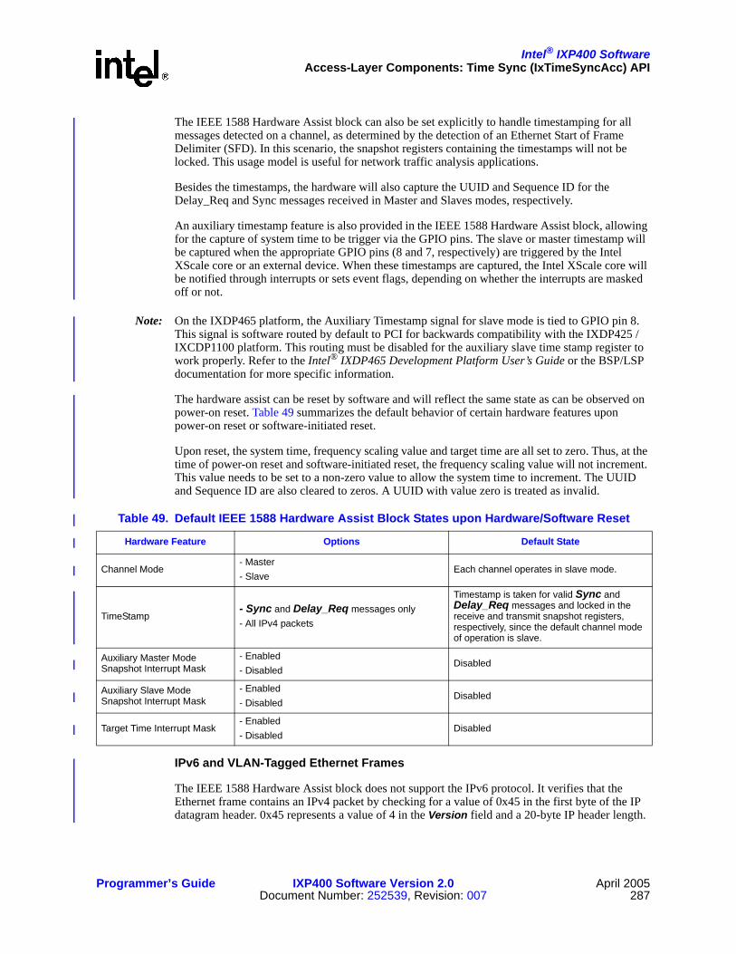
Intel® IXP400 SoftwareAccess-Layer Components: Time Sync (IxTimeSyncAcc) API
Programmer’s Guide IXP400 Software Version 2.0 April 2005Document Number: 252539, Revision: 007 287
The IEEE 1588 Hardware Assist block can also be set explicitly to handle timestamping for all messages detected on a channel, as determined by the detection of an Ethernet Start of Frame Delimiter (SFD). In this scenario, the snapshot registers containing the timestamps will not be locked. This usage model is useful for network traffic analysis applications.
Besides the timestamps, the hardware will also capture the UUID and Sequence ID for the Delay_Req and Sync messages received in Master and Slaves modes, respectively.
An auxiliary timestamp feature is also provided in the IEEE 1588 Hardware Assist block, allowing for the capture of system time to be trigger via the GPIO pins. The slave or master timestamp will be captured when the appropriate GPIO pins (8 and 7, respectively) are triggered by the Intel XScale core or an external device. When these timestamps are captured, the Intel XScale core will be notified through interrupts or sets event flags, depending on whether the interrupts are masked off or not.
Note: On the IXDP465 platform, the Auxiliary Timestamp signal for slave mode is tied to GPIO pin 8. This signal is software routed by default to PCI for backwards compatibility with the IXDP425 / IXCDP1100 platform. This routing must be disabled for the auxiliary slave time stamp register to work properly. Refer to the Intel® IXDP465 Development Platform User’s Guide or the BSP/LSP documentation for more specific information.
The hardware assist can be reset by software and will reflect the same state as can be observed on power-on reset. Table 49 summarizes the default behavior of certain hardware features upon power-on reset or software-initiated reset.
Upon reset, the system time, frequency scaling value and target time are all set to zero. Thus, at the time of power-on reset and software-initiated reset, the frequency scaling value will not increment. This value needs to be set to a non-zero value to allow the system time to increment. The UUID and Sequence ID are also cleared to zeros. A UUID with value zero is treated as invalid.
IPv6 and VLAN-Tagged Ethernet Frames
The IEEE 1588 Hardware Assist block does not support the IPv6 protocol. It verifies that the Ethernet frame contains an IPv4 packet by checking for a value of 0x45 in the first byte of the IP datagram header. 0x45 represents a value of 4 in the Version field and a 20-byte IP header length.
Table 49. Default IEEE 1588 Hardware Assist Block States upon Hardware/Software Reset
Hardware Feature Options Default State
Channel Mode- Master- Slave
Each channel operates in slave mode.
TimeStamp- Sync and Delay_Req messages only- All IPv4 packets
Timestamp is taken for valid Sync and Delay_Req messages and locked in the receive and transmit snapshot registers, respectively, since the default channel mode of operation is slave.
Auxiliary Master Mode Snapshot Interrupt Mask
- Enabled- Disabled
Disabled
Auxiliary Slave Mode Snapshot Interrupt Mask
- Enabled- Disabled
Disabled
Target Time Interrupt Mask- Enabled- Disabled
Disabled

Intel® IXP400 SoftwareAccess-Layer Components: Time Sync (IxTimeSyncAcc) API
April 2005 IXP400 Software Version 2.0 Programmer’s Guide288 Document Number: 252539, Revision: 007
VLAN-tagged Ethernet frames include an additional four bytes prior to the beginning of the original Ethernet Type/Length field. The IP header immediately follows the Type/Length field. VLAN-tagged Ethernet frames can be identified by the value of 0x8100 at offset 12 and 13 of the Ethernet frame. If the IEEE 1588 Hardware Assist block identifies a value of 0x8100 (i.e., VLAN TPID field) at this offset, it will adjust the offsets it uses to support PTP messages by four bytes.
Note: Some popular Ethernet switch PHY chips use the same bytes in VLAN-tagged frames to encode the port through which a frame is received. These devices encode the physical port from which a frame is received in the least-significant four bits of offset 13. The IEEE 1588 Hardware Assist block will be unable to detect Sync and Delay_Req messages in this scenario.
Additional Hardware Information
For more information on the IEEE 1588 Hardware Assist block, please refer to the Intel hardware documentation for the Intel® IXP46X Product Line.
20.2.3 IxTimeSyncAccThe IxTimeSyncAcc access-layer component provides a software interface to configure the IEEE 1588 Hardware Assist block, and provide access to the snapshot register data. More details are provided in “IxTimeSyncAcc API Details” on page 288.
20.2.4 IEEE 1588 PTP Client ApplicationA IEEE 1588 PTP client application is application code running on the Intel XScale core that utilizes the IxTimeSyncAcc API (and other APIs in the IXP400 software) to implement and use PTP messages and timestamps according to the IEEE 1588 specifications.
The IXP400 software does not provide this client application, although it does include a codelet that demonstrates the basic usage of the APIs in some IEEE 1588 scenarios. Refer to Chapter 23.
A common scenario would involve a IEEE 1588 client application implementing a slave, master, or boundary clock on the target hardware platform. When transmitting PTP protocol messages, the client application would need to obtain the appropriate timestamp information from IxTimeSyncAcc, construct the appropriate PTP protocol messages, and transmit the messages using the Ethernet subsystem of the IXP400 software. When receiving PTP protocol messages, the client application may poll via the IxTimeSyncAcc API for the existence of new timestamp and other related PTP message information. If the remainder of the PTP message content is of interest to the client application, it will need to receive the Ethernet frame via the Ethernet subsystem of the IXP400 software (i.e., IxEthAcc).
When operating over Ethernet networks, these messages are carried in frames using the UDP transport-layer. UDP does not guarantee successful message transfer between sending and receiving nodes, and the IEEE 1588 client application must take this behavior into account.
20.3 IxTimeSyncAcc API Details
20.3.1 Features
IxTimeSyncAcc API provides the following features:

Intel® IXP400 SoftwareAccess-Layer Components: Time Sync (IxTimeSyncAcc) API
Programmer’s Guide IXP400 Software Version 2.0 April 2005Document Number: 252539, Revision: 007 289
• Configure the PTP Ports (NPE channels) to operate in master or slave mode
• Poll for Sent Timestamp of the Sync and Delay_Req messages in both master and slave modes
• Poll for Receive Timestamp of the Delay_Req and Sync messages in both master and slave modes
• Poll for Timestamp of all messages Sent or Received irrespective of master or slave mode
• Set and retrieve System Time
• Set and retrieve Frequency Scaling Value, based upon which the System Time will be incremented
• Enable and disable system time exceeded or equaled target time notification interrupt
• Inform when system time exceeds or equals target time through a client callback
• Poll to test whether system time exceeds or is equal to the target time
• Set and retrieve Target Time
• Inform when auxiliary master or slave timestamp captured through client callback
• Poll for auxiliary master or slave timestamp
• Enable and disable auxiliary timestamp notification interrupt
• Reset IEEE 1588 Hardware Assist block to the default state as observed upon power-on reset
• Get or clear statistics on packets transmitted and received (depending on the NPE channel mode configuration, all Ethernet or Sync & Delay_Req messages).
• Show the configuration details of the IEEE 1588 Hardware Assist block (i.e., contents of control and event registers, all snapshot registers, interrupts/events asserted or pending).
20.3.2 DependenciesDependencies for IxTimeSyncAcc are shown in “IxTimeSyncAcc Component Dependencies” on page 284. These dependencies include:
• IxFeatureCtrl – This component is used to verify support for the IEEE 1588 Hardware Assist block in the Intel® IXP4XX product line and IXC1100 control plane processors. It also is used to confirm the availability of NPE ports.
• IxOSAL – This component makes use of the IxOSAL services for error logging or reporting as part of the standard error handling mechanism in the IXP400 software. IxOSAL also provide mutex locking, ISR registration, and access to hardware registers.
Note: Depending on the design and purpose of the client application, dependencies may exist to other access components besides IxTimeSyncAcc and the dependencies listed here.
20.3.3 Error HandlingIxTimeSyncAcc returns IX_FAIL and other status values under the following circumstances:
• Inappropriate parameter values passed to an API
• Incorrect sequence of invocation of the APIs
• Polled mode request while interrupt mode is set

Intel® IXP400 SoftwareAccess-Layer Components: Time Sync (IxTimeSyncAcc) API
April 2005 IXP400 Software Version 2.0 Programmer’s Guide290 Document Number: 252539, Revision: 007
• Internal errors
IxTimeSyncAcc returns IX_SUCCESS when errors are not observed. The client application is expected to handle these errors/values appropriately.
20.4 IxTimeSyncAcc API Usage ScenariosThe following scenarios present usage examples of the interface by a client application. They are each independent but, depending on the needs of the client application, could be intermixed.
20.4.1 Polling for Transmit and Receive TimestampsThe IEEE 1588 Hardware Assist block detects a PTP message and then sets an event flag. The client application may poll for receive and/or transmit timestamps before or after the actual Sync/Delay_Req message detection, which sets the event flags. The timestamps returned are valid only when the respective event flags are set. After the valid timestamps are retrieved, the event flags are cleared to allow for capturing new timestamps.
The IEEE 1588 Hardware Assist block indicates the availability of transmit and receive timestamps on the MII interfaces through events only. In other words, interrupts are not defined for these conditions (unlike the auxiliary timestamps and target time reached conditions, described later). The client application has to poll for these events to obtain the timestamps.
Figure 97 presents the timestamp polling flow..
20.4.2 Interrupt Mode OperationsThe IxTimeSyncAcc component uses a single interrupt on IXP46X network processors to provide the client application with Target Time hit conditions or Auxiliary Master/Slave Timestamps. It implements the following priority order when the interrupt is asserted to the Intel XScale core:
1. Target Time Reached/Hit Condition
Figure 97. Polling for Timestamps of Sync or Delay_Req
B4393-01
Client Application IEEE 1588 Hardware Assist BlockIxTimeSyncAcc
ixTimeSyncAccSystemTimeSet (systemTime)
ixTimeSyncAccTickRateSet (tickRate)
ixTimeSyncAccPTPPortConfigSet(ptpPort,ptpPortMode)
Set system time
Set frequency scaling factor
Set port mode - Master/Slave
Sync/Delay_Req detected(Sent and/or Received)
Set event flags for sent and/or received system time snapshot
ixTimeSyncAccPTPRxPoll (ptpPort,*ptpMsgData)
ixTimeSyncAccPTPTxPoll (ptpPort,*ptpMsgData) Get receive snapshot data for Port #n
Get transmit snapshot data for Port #n

Intel® IXP400 SoftwareAccess-Layer Components: Time Sync (IxTimeSyncAcc) API
Programmer’s Guide IXP400 Software Version 2.0 April 2005Document Number: 252539, Revision: 007 291
2. Auxiliary Master Timestamp
3. Auxiliary Slave Timestamp
In order to avoid repeated invocation of the Interrupt Service Routing for the “target time reached” condition, the client application callback routine will need to either disable the interrupt handling, invoke the API to set the target time to a different value, or change the system timer value.
Figure 98 presents a scenario where the system time and target time are set, a “target time reached” condition is met, and an interrupt is used to notify the client application. A polled-mode scenario would operate similarly to what is described in “Polled Mode Operations” on page 291.
20.4.3 Polled Mode OperationsTarget Time events and Auxiliary snapshots can also be serviced with polling by the client application. Figure 99 shows a scenario where the client application uses polling to periodically retrieve auxiliary snapshot data.
Figure 98. Interrupt Servicing of Target Time Reached Condition
IEEE 1588 Hardware Assist Block
B4394-01
Client Application IxTimeSyncAcc
ixTimeSyncAccSystemTimeSet (systemTime)
ixTimeSyncAccTickRateSet (tickRate)
ixTimeSyncAccTargetTimeSet(targetTime)
Set system time
Set frequency scaling factor
Set target time
Get target time
ixTimeSyncAccTargetTimeInterruptEnable(targetTimeCallback)
Enable Target Time Interrupt
(*IxTimeSyncAccTargetTimeCallback)(targetTime)
Register Callback
Invoke ISR
Invoke Callback
System Time >= Target TimeInterrupt Triggered

Intel® IXP400 SoftwareAccess-Layer Components: Time Sync (IxTimeSyncAcc) API
April 2005 IXP400 Software Version 2.0 Programmer’s Guide292 Document Number: 252539, Revision: 007
Figure 99. Polling for Auxiliary Snapshot Values
B4391-01
Client Application IEEE 1588 Hardware AssistIxTimeSyncAcc
ixTimeSyncAccSystemTimeSet (systemTime)
ixTimeSyncAccTickRateSet (tickRate) Set system time
Set frequency scaling factor
ixTimeSyncAccAuxTimePoll (auxMode,*auxTime)
GPIO input assert
Get auxiliary time of the desired mode
Aux. Timestamp Capturedand Event Set

Intel® IXP400 Software
Programmer’s Guide IXP400 Software Version 2.0 April 2005Document Number: 252539, Revision: 007 293
Access-Layer Components:UART-Access (IxUARTAcc) API 21
This chapter describes the Intel® IXP400 Software v2.0’s “UART-Access API” access-layer component.
21.1 What’s NewThere are no changes or enhancements to this component in software release 2.0.
21.2 OverviewThe UARTs of the Intel® IXP4XX Product Line of Network Processors and IXC1100 Control Plane Processor have been modeled on the industry standard 16550 UART. There are, however, some differences between them which prevents the unmodified use of 16550-based UART drivers. They support baud rates between 9,600 bps and 912.6 Kbps.
The higher data rates allow the possibility of using the UART as a connection to a data path module, such as Bluetooth*. While the UART is instantiated twice on the IXP4XX product line and IXC1100 control plane processors, the same low-level routines will be used by both. The default configuration for the processor is:
• UART0 — Debug Port (console)
• UART1 — Fast UART (e.g., Bluetooth)
Any combination of debug or high-speed UART, however, could be used.
A generic reference implementation is provided that can be used as an example for other implementations/operating systems. These routines are meant to be stand-alone, such that they do not require an operating system to execute. If a new operating system is later added to those supported, these routines can be easily modified to link in to that platform, without the need for extensive rework.
The UART driver provides generic support for polled and loop back mode only.
21.3 Interface DescriptionThe API covers the following functions:
• Device initialization
• UART char output
• UART char input

Intel® IXP400 SoftwareAccess-Layer Components: UART-Access (IxUARTAcc) API
April 2005 IXP400 Software Version 2.0 Programmer’s Guide294 Document Number: 252539, Revision: 007
• UART IOCTL
• Baud rate set/get
• Parity
• Number of stop bits
• Character length 5, 6, 7, 8
• Enable/disable hardware flow control for Clear to Send (CTS) and Request to Send (RTS) signals
21.4 UART / OS DependenciesThe UART device driver is an API than can be used to transmit/receive data from either of the two UART ports on the processor. However, it is expected that an RTOS will provide standard UART services independent from the IxUartAcc device driver. That is, the RTOS UART services will configure and utilize the UART registers and FIFOs directly.
Users of the IxUartAcc component should ensure that the use of this device driver does not conflict with any UART services provided by the RTOS.
21.4.1 FIFO Versus Polled ModeThe UART supports both FIFO and polled mode operation. Polled mode is the simpler of the two to implement, but is also the most processor-intensive since it relies on the Intel XScale® Core to check for data.
The device’s Receive Buffer Register (RBR) must be polled at frequent intervals to ascertain if data is available. This must be done frequently to avoid the possibility of buffer overrun. Similarly, it checks the Transmit Buffer Register (TBR) for when it can send another character.
The FIFO on the processor’s UART is 64 bytes deep in both directions. The transmit FIFO is 8 bits wide and the receive FIFO is 11 bits wide. The receive FIFO is wider to accommodate the potentially largest data word (i.e., including optional stop bits and parity 8+2+1 = 11).
Interrupts can occur in one of two ways. One is when the FIFO has reached its programmed trigger level (set by the FIFO Control Register [FCR]). The other is when a character timeout has occurred (also set in the FCR). The driver will implement both modes of operation.
The default setup for the UART is:
• 9,600 bps baud rate
• 8-bit data word
• One stop bit
• No parity
• No flow control
• Interrupt mode (Polled for generic interface)

Intel® IXP400 SoftwareAccess-Layer Components: UART-Access (IxUARTAcc) API
Programmer’s Guide IXP400 Software Version 2.0 April 2005Document Number: 252539, Revision: 007 295
21.5 Dependencies
Figure 100. UART Services Models
Standard RTOS UART Services IxUartAcc Service Model
UART Registers /FIFOs
UART Registers /FIFOs
OS I/O Services API
OS Serial Driver
User Application
Supported RTOS
IxUartAcc
IXP400Access LayerComponents
User Application
B2445-01

This page is intentionally left blank.
Intel® IXP400 Software
April 2005 IXP400 Software Version 2.0 Programmer’s Guide296 Document Number: 252539, Revision: 007

Intel® IXP400 Software
Programmer’s Guide IXP400 Software Version 2.0 April 2005Document Number: 252539, Revision: 007 297
Access-Layer Components:USB Access (ixUSB) API 22
This chapter describes the Intel® IXP400 Software v2.0’s “USB Access API” access-layer component.
22.1 What’s NewThere are no changes or enhancements to this component in software release 2.0.
22.2 OverviewThe Intel® IXP4XX Product Line of Network Processors and IXC1100 Control Plane Processors’ USB hardware components comply with the 1.1 version of the Universal Serial Bus (USB) standard.
22.3 USB Controller BackgroundThe IXP4XX product line and IXC1100 control plane processors’ Universal Serial Bus Device Controller (UDC) supports 16 endpoints and can operate half-duplex at a baud rate of 12 Mbps (slave only, not a host or hub controller).
The serial information transmitted by the UDC contains layers of communication protocols, the most basic of which are fields. UDC fields include:
Fields are used to produce packets. Depending on the function of a packet, a different combination and number of fields are used. Packet types include:
Packets are then assembled into groups to produce frames. These frames or transactions fall into four groups:
• Sync • Endpoint • Data
• Packet identifier • Frame number • CRC
• Address
• Token • Handshake
• Data • Special
• Bulk • Interrupt
• Control • Isochronous

Intel® IXP400 SoftwareAccess-Layer Components: USB Access (ixUSB) API
April 2005 IXP400 Software Version 2.0 Programmer’s Guide298 Document Number: 252539, Revision: 007
Endpoint 0, by default, is used only to communicate control transactions to configure the UDC after it is reset or hooked up (physically connected to an active USB host or hub). Endpoint 0’s responsibilities include:
The USB protocol uses differential signaling between the two pins for half-duplex data transmission. A 1.5-KΩ pull-up resistor is required to be connected to the USB cable’s D+ signal to pull the UDC+ pin high when polarity for data transmission is needed.
Using differential signaling allows multiple states to be transmitted on the serial bus. These states are combined to transmit data, as well as various bus conditions, including: idle, resume, start of packet, end of packet, disconnect, connect, and reset.
USB transmissions are scheduled in 1-ms frames. A frame starts with a SOF (Start-Of-Frame) packet and contains USB packets. All USB transmissions are regarded from the host’s point of view: IN means towards the host and OUT means towards the device.
22.3.1 Packet FormatsUSB supports four packet types:
A token packet is placed at the beginning of a frame, and is used to identify OUT, IN, SOF, and SETUP transactions. OUT and IN frames are used to transfer data., SOF packets are used to time isochronous transactions, and SETUP packets are used for control transfers to configure endpoints. An IN, OUT and SETUP token packet consists of a sync, a PID, an address, an endpoint, and a CRC5 field.
For OUT and SETUP transactions, the address and endpoint fields are used to select which UDC endpoint is to receive the data, and for an IN transaction, which endpoint must transmit data. A PRE (Preamble) PID precedes a low-speed (1.5 Mbps) USB transmission. The UDC supports full-speed (12 Mbps) USB transfers only. PRE packets signifying low-speed devices are ignored as well as the low-speed data transfer that follows.
A Start Of Frame (SOF) is a special type of token packet that is issued by the host at a nominal interval of once every 1 ms +/- 0.0005 ms. SOF packets consist of a sync, a PID, a frame number (which is incremented after each frame is transmitted), and a CRC5 field, as shown in Table 51. The presence of SOF packets every 1ms prevents the UDC from going into suspend mode.
• Connection • Endpoint configuration • Disconnect
• Address assignment • Bus enumeration
• Token • Handshake
• Data • Special
Table 50. IN, OUT, and SETUP Token Packet Format
8 Bits 8 Bits 7 Bits 4 Bits 5 Bits
Sync PID Address Endpoint CRC5
Table 51. SOF Token Packet Format
8 Bits 8 Bits 11 Bits 5 Bits
Sync PID Frame Number CRC5

Intel® IXP400 SoftwareAccess-Layer Components: USB Access (ixUSB) API
Programmer’s Guide IXP400 Software Version 2.0 April 2005Document Number: 252539, Revision: 007 299
Data packets follow token packets, and are used to transmit data between the host and UDC. There are two types of data packets as specified by the PID: DATA0 and DATA1. These two types are used to provide a mechanism to guarantee data sequence synchronization between the transmitter and receiver across multiple transactions.
During the handshake phase, both communicate and agree which data token type to transmit first. For each subsequent packet transmitted, the data packet type is toggled (DATA0, DATA1, DATA0, and so on). A data packet consists of a sync, a PID, from 0 to 1,023 bytes of data, and a CRC16 field, as shown in Table 52. Note that the UDC supports a maximum of 8 bytes of data for an Interrupt IN data payload, a maximum of 64 bytes of data for a Bulk data payload, and a maximum of 256 bytes of data for an Isochronous data payload.
Handshake packets consist of only a sync and a PID. Handshake packets do not contain a CRC because the PID contains its own check field. They are used to report data transaction status, including whether data was successfully received, flow control, and stall conditions. Only transactions that support flow control can return handshakes.
The three types of handshake packets are: ACK, NAK, and STALL.
• ACK — Indicates that a data packet was received without bit stuffing, CRC, or PID check errors.
• NAK — Indicates that the UDC was unable to accept data from the host, or it has no data to transmit.
• STALL — Indicates that the UDC is unable to transmit or receive data, and requires host intervention to clear the stall condition.
Bit stuffing, CRC, and PID errors are signaled by the receiving unit by omitting a handshake packet. Table 53 shows the format of a handshake packet.
22.3.2 Transaction FormatsPackets are assembled into groups to form transactions. Four different transaction formats are used in the USB protocol. Each is specific to a particular endpoint type: bulk, control, interrupt, and isochronous. Endpoint 0, by default, is a control endpoint and receives only control transactions.
The host controller initiates all USB transactions, and transmission takes place between the host and UDC one direction at a time (half-duplex).
Bulk transactions guarantee error-free transmission of data between the host and UDC by using packet-error detection and retry. The host schedules bulk packets when there is available time on the bus. The three packet types used to construct bulk transactions are: token, data, and handshake.
Table 52. Data Packet Format
8 Bits 8 Bits 0–1,023 Bytes 16 Bits
Sync PID Data CRC16
Table 53. Handshake Packet Format
8 Bits 8 Bits
Sync PID

Intel® IXP400 SoftwareAccess-Layer Components: USB Access (ixUSB) API
April 2005 IXP400 Software Version 2.0 Programmer’s Guide300 Document Number: 252539, Revision: 007
The eight possible types of bulk transactions based on data direction, error, and stall conditions are shown in Table 54. (Packets sent by the UDC to the host are highlighted in boldface type. Packets sent by the host to the UDC are not boldfaced.)
Isochronous transactions guarantee constant rate, error-tolerant transmission of data between the host and UDC. The host schedules isochronous packets during every frame on the USB, typically 1 ms, 2 ms, or 4 ms.
USB protocol allows for isochronous transfers to take up to 90% of the USB bandwidth. Unlike bulk transactions, if corrupted data is received, the UDC will continue to process the corrupted data that corresponds to the current start of frame indicator.
Isochronous transactions do not support a handshake phase or retry capability. The two packet types used to construct isochronous transactions are token and data. The two possible types of isochronous transactions, based on data direction, are shown in Table 55.
Control transactions are used by the host to configure endpoints and query their status. Like bulk transactions, control transactions begin with a setup packet, followed by an optional data packet, then a handshake packet. Note that control transactions, by default, use DATA0 type transfers. Table 56 shows the four possible types of control transactions.
Table 54. Bulk Transaction Formats
Action Token Packet Data Packet Handshake Packet
Host successfully received data from UDC In DATA0/DATA1 ACK
UDC temporarily unable to transmit data In None NAK
UDC endpoint needs host intervention In None STALL
Host detected PID, CRC, or bit-stuff error In DATA0/DATA1 None
UDC successfully received data from host Out DATA0/DATA1 ACK
UDC temporarily unable to receive data Out DATA0/DATA1 NAK
UDC endpoint needs host intervention Out DATA0/DATA1 STALL
UDC detected PID, CRC, or bit stuff error Out DATA0/DATA1 None
NOTE: Packets from UDC to host are boldface.
Table 55. Isochronous Transaction Formats
Action Token Packet Data Packet
Host successfully received data from UDC In DATA0/DATA1
UDC successfully received data from host Out DATA0/DATA1
NOTE: Packets from UDC to host are boldface.

Intel® IXP400 SoftwareAccess-Layer Components: USB Access (ixUSB) API
Programmer’s Guide IXP400 Software Version 2.0 April 2005Document Number: 252539, Revision: 007 301
Control transfers are assembled by the host by sending a control transaction to tell the UDC what type of control transfer is taking place (control read or control write), followed by two or more bulk data transactions. The first stage of the control transfer is the setup. The device must either respond with an ACK; or if the data is corrupted, it sends no handshake.
The control transaction, by default, uses a DATA0 transfer, and each subsequent bulk data transaction toggles between DATA1 and DATA0 transfers. For a control write to an endpoint, OUT transactions are used. For control reads, IN transactions are used.
The transfer direction of the last bulk data transaction is reversed. It is used to report status and functions as a handshake. The last bulk data transaction always uses a DATA1 transfer by default (even if the previous bulk transaction used DATA1). For a control write, the last transaction is an IN from the UDC to the host, and for a control read, the last transaction is an OUT from the host to the UDC.
Interrupt transactions are used by the host to query the status of the device. Like bulk transactions, interrupt transactions begin with a setup packet, followed by an optional data packet, then a handshake packet. Table 58 shows the eight possible types of interrupt transactions.
Table 56. Control Transaction Formats, Set-Up Stage
Action Token Packet Data Packet Handshake Packet
UDC successfully received control from host Setup DATA0 ACK
UDC temporarily unable to receive data Setup DATA0 NAK
UDC endpoint needs host intervention Setup DATA0 STALL
UDC detected PID, CRC, or bit stuff error Setup DATA0 None
NOTE: Packets from UDC to host are boldface.
Table 57. Control Transaction Formats
Control Write Setup DATA (BULK OUT) STATUS (BULK IN)
Control read Setup DATA (BULK IN)* STATUS (BULK OUT)
NOTE: Packets from UDC to host are boldface.
Table 58. Interrupt Transaction Formats
Action Token Packet Data Packet Handshake Packet
Host successfully received data from UDC In DATA0/DATA1 ACK
UDC temporarily unable to transmit data In None NAK
UDC endpoint needs host intervention In None STALL
Host detected PID, CRC, or bit stuff error In DATA0/DATA1 None
UDC successfully received data from host Out DATA0/DATA1 ACK
UDC temporarily unable to receive data Out DATA0/DATA1 NAK
UDC endpoint needs host intervention Out DATA0/DATA1 STALL
UDC detected PID, CRC, or bit stuff error Out DATA0/DATA1 None
NOTE: Packets from UDC to host are boldface.

Intel® IXP400 SoftwareAccess-Layer Components: USB Access (ixUSB) API
April 2005 IXP400 Software Version 2.0 Programmer’s Guide302 Document Number: 252539, Revision: 007
22.4 ixUSB API Interfaces
The ixUSB API components operate within a callback architecture. Initial device setup and configuration is controlled through the callback registered during the ixUSBSetupCallbackRegister function. Data reception occurs through the callback registered during the ixUSBReceiveCallbackRegister function. Special events are signalled to the callback registered during the ixUSBEventCallbackRegister function.
Prior to using any other ixUSB API, the ixUSB client must initialize the controller with the ixUSBDriverInit API call. After this call the driver is in a disabled state. The call to ixUSBDeviceEnable allows data, setup, and configuration transmissions to flow.
22.4.1 ixUSB Setup RequestsThe UDC’s control, status, and data registers are used only to control and monitor the transmit and receive FIFOs for endpoints 1 - 15. All other UDC configuration and status reporting are controlled by the host, via the USB, using device requests that are sent as control transactions to endpoint 0. Each data packet of a setup stage to endpoint 0 is 8 bytes long and specifies:
• Data transfer direction
— Host to device
— Device to host
Table 59. API interfaces Available for Access Layer
API Description
ixUSBDriverInit Initialize driver and USB Device Controller.
ixUSBDeviceEnable Enable or disable the device.
ixUSBEndpointStall Enable or disable endpoint stall.
ixUSBEndpointClear Free all Rx/Tx buffers associated with an endpoint.
ixUSBSignalResume Trigger signal resuming on the bus.
ixUSBFrameCounterGet Retrieve the 11-bit frame counter.
ixUSBReceiveCallbackRegister Register a data-receive callback.
ixUSBSetupCallbackRegister Register a setup-receive callback.
ixUSBBufferSubmit Submit a buffer for transmit.
ixUSBBufferCancel Cancel a buffer previously submitted for transmitting.
ixUSBEventCallbackRegister Register an event callback.
ixUSBIsEndpointStalled Retrieve an endpoint's stall status.
ixUSBStatisticsShow Display device state and statistics.
ixUSBErrorStringGet Convert an error code into a human-readable string error message.
ixUSBEndpointInfoShow Display endpoint information table.
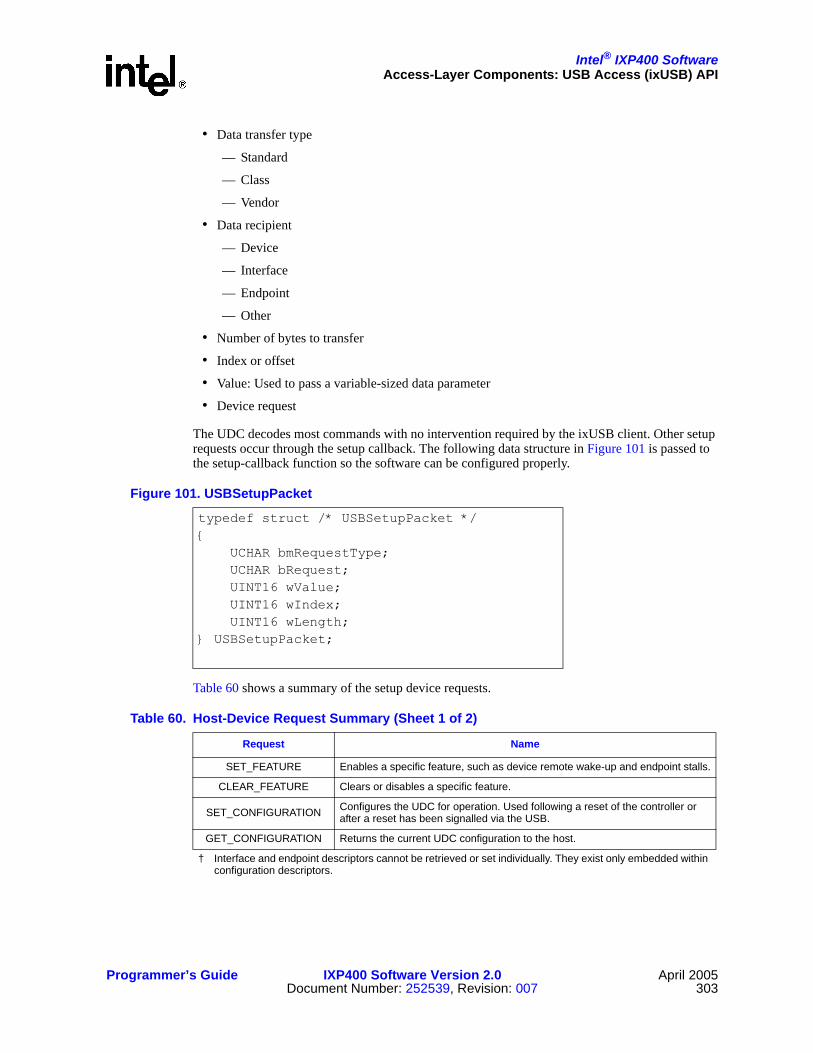
Intel® IXP400 SoftwareAccess-Layer Components: USB Access (ixUSB) API
Programmer’s Guide IXP400 Software Version 2.0 April 2005Document Number: 252539, Revision: 007 303
• Data transfer type
— Standard
— Class
— Vendor
• Data recipient
— Device
— Interface
— Endpoint
— Other
• Number of bytes to transfer
• Index or offset
• Value: Used to pass a variable-sized data parameter
• Device request
The UDC decodes most commands with no intervention required by the ixUSB client. Other setup requests occur through the setup callback. The following data structure in Figure 101 is passed to the setup-callback function so the software can be configured properly.
Table 60 shows a summary of the setup device requests.
Figure 101. USBSetupPacket
typedef struct /* USBSetupPacket */ UCHAR bmRequestType; UCHAR bRequest; UINT16 wValue; UINT16 wIndex; UINT16 wLength; USBSetupPacket;
Table 60. Host-Device Request Summary (Sheet 1 of 2)
Request Name
SET_FEATURE Enables a specific feature, such as device remote wake-up and endpoint stalls.
CLEAR_FEATURE Clears or disables a specific feature.
SET_CONFIGURATION Configures the UDC for operation. Used following a reset of the controller or after a reset has been signalled via the USB.
GET_CONFIGURATION Returns the current UDC configuration to the host.
† Interface and endpoint descriptors cannot be retrieved or set individually. They exist only embedded within configuration descriptors.

Intel® IXP400 SoftwareAccess-Layer Components: USB Access (ixUSB) API
April 2005 IXP400 Software Version 2.0 Programmer’s Guide304 Document Number: 252539, Revision: 007
Via control endpoint 0, the user must decode and respond to the GET_DESCRIPTOR command.
Refer to the Universal Serial Bus Specification Revision 1.1 for a full description of host-device requests.
22.4.1.1 Configuration
In response to the GET_DESCRIPTOR command, the user sends back a description of the UDC configuration. The UDC can physically support more data-channel bandwidth than the USB will allow. When responding to the host, the user must be careful to specify a legal USB configuration.
For example, if the user specifies a configuration of six isochronous endpoints of 256 bytes each, the host will not be able to schedule the proper bandwidth and will not take the UDC out of Configuration 0. The user must determine which endpoints to not tell the host about, so that they will not get used.
Another option, especially attractive for isochronous endpoints, is to describe a configuration of less than 256 bytes maximum packet to the host. The direction of the endpoints is fixed and the UDC will physically support only the following maximum packet sizes:
• Interrupt endpoints — 8 bytes
• Bulk endpoints — 64 bytes
• Isochronous endpoints — 256 bytes
In order to increase flexibility, the UDC supports a total of four configurations. While each of these configurations is identical within the UDC, the software can be used to make three distinct configurations. Configuration 0 is a default configuration of endpoint 0 only.
For a detailed description of the configuration descriptor, see the USB 1.1 specification.
SET_DESCRIPTOR
Sets existing descriptors or adds new descriptors.Existing descriptors include: †
• Device • Configuration • String• Interface • Endpoint
GET_DESCRIPTOR Returns the specified descriptor, if it exists.
SET_INTERFACE Selects an alternate setting for the UDC’s interface.
GET_INTERFACE Returns the selected alternate setting for the specified interface.
GET_STATUSReturns the UDC’s status including:
• Remote wake-up • Self-powered • Data direction• Endpoint number • Stall status
SET_ADDRESS Sets the UDC’s 7-bit address value for all future device accesses.
SYNCH_FRAME Sets an endpoint’s synchronization frame.
Table 60. Host-Device Request Summary (Sheet 2 of 2)
Request Name
† Interface and endpoint descriptors cannot be retrieved or set individually. They exist only embedded within configuration descriptors.

Intel® IXP400 SoftwareAccess-Layer Components: USB Access (ixUSB) API
Programmer’s Guide IXP400 Software Version 2.0 April 2005Document Number: 252539, Revision: 007 305
22.4.1.2 Frame Synchronization
The SYNCH_FRAME request is used by isochronous endpoints that use implicit-pattern synchronization. The isochronous endpoints may need to track frame numbers in order to maintain synchronization.
Isochronous-endpoint transactions may vary in size, according to a specific repeating pattern. The host and endpoint must agree on which frame begins the repeating pattern. The host uses this request to specify the exact frame on which the repeating pattern begins.
The data stage of the SYNCH_FRAME request contains the frame number in which the pattern begins. Having received the frame number, the device can start monitoring each frame number sent during the SOF. This is recorded in the frame counter and made available through specific driver functions (see ixUSBFrameCounterGet).
22.4.2 ixUSB Send and Receive RequestsThe USB access layer encodes and decodes data frames sending and receiving buffers to and from the client in the same format as IX_MBUF.
Buffers are sent from the UDC to the host with the ixUSBBufferSubmit API.
Data buffers are received from the host through the callback function registered with the access layer during the ixUSBReceiveCallbackRegister API call.
22.4.3 ixUSB Endpoint Stall FeatureA device uses the STALL handshake in one of two distinct occasions.
The first case — known as “functional stall” — is when the Halt feature, associated the endpoint, is set. A special case of the functional stall is the “commanded stall.” Commanded stall occurs when the host explicitly sets the endpoint’s Halt feature using the SET_FEATURE command.
Once a function’s endpoint is halted, the function must continue returning STALL packets until the condition causing the halt has been cleared through host intervention (using SET_FEATURE). This can happen both for IN and OUT endpoints. In the case of IN endpoints, the endpoint sends a STALL handshake immediately after receiving an IN token. For OUT endpoints the STALL handshake is sent as soon as the data packet after the OUT token is received.
Figure 102. STALL on IN Transactions
Host
IN Token
Device
STALL
BusRequest Reply
B2418-01
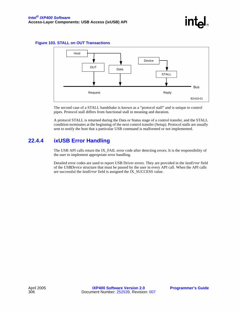
Intel® IXP400 SoftwareAccess-Layer Components: USB Access (ixUSB) API
April 2005 IXP400 Software Version 2.0 Programmer’s Guide306 Document Number: 252539, Revision: 007
The second case of a STALL handshake is known as a “protocol stall” and is unique to control pipes. Protocol stall differs from functional stall in meaning and duration.
A protocol STALL is returned during the Data or Status stage of a control transfer, and the STALL condition terminates at the beginning of the next control transfer (Setup). Protocol stalls are usually sent to notify the host that a particular USB command is malformed or not implemented.
22.4.4 ixUSB Error HandlingThe USB API calls return the IX_FAIL error code after detecting errors. It is the responsibility of the user to implement appropriate error handling.
Detailed error codes are used to report USB Driver errors. They are provided in the lastError field of the USBDevice structure that must be passed by the user in every API call. When the API calls are successful the lastError field is assigned the IX_SUCCESS value.
Figure 103. STALL on OUT Transactions
Host
OUT
Device
STALL
BusRequest Reply
Data
B2419-01

Intel® IXP400 SoftwareAccess-Layer Components: USB Access (ixUSB) API
Programmer’s Guide IXP400 Software Version 2.0 April 2005Document Number: 252539, Revision: 007 307
Table 61. Detailed Error Codes
#ifndef IX_USB_ERROR_BASE#define IX_USB_ERROR_BASE 4096#endif /* IX_USB_ERROR_BASE */
/* error due to unknown reasons */
#define IX_USB_ERROR(IX_USB_ERROR_BASE + 0)
/* invalid USBDevice structure passed as parameter or no device present */#define IX_USB_INVALID_DEVICE (IX_USB_ERROR_BASE + 1)
/* no permission for attempted operation */#define IX_USB_NO_PERMISSION(IX_USB_ERROR_BASE + 2)
/* redundant operation */#define IX_USB_REDUNDANT(IX_USB_ERROR_BASE + 3)
/* send queue full */#define IX_USB_SEND_QUEUE_FULL(IX_USB_ERROR_BASE + 4)
/* invalid endpoint */#define IX_USB_NO_ENDPOINT(IX_USB_ERROR_BASE + 5)
/* no IN capability on endpoint */#define IX_USB_NO_IN_CAPABILITY(IX_USB_ERROR_BASE + 6)
/* no OUT capability on endpoint */#define IX_USB_NO_OUT_CAPABILITY(IX_USB_ERROR_BASE + 7)
/* transfer type incompatible with endpoint */#define IX_USB_NO_TRANSFER_CAPABILITY(IX_USB_ERROR_BASE + 8)
/* endpoint stalled */#define IX_USB_ENDPOINT_STALLED(IX_USB_ERROR_BASE + 9)
/* invalid parameter(s) */#define IX_USB_INVALID_PARMS(IX_USB_ERROR_BASE + 10)
NOTE: “Error due to unknown reasons” — This code is also used when there is only one possible error reason and the error was already signaled by the IX_FAIL return code.

Intel® IXP400 SoftwareAccess-Layer Components: USB Access (ixUSB) API
April 2005 IXP400 Software Version 2.0 Programmer’s Guide308 Document Number: 252539, Revision: 007
22.5 USB Data FlowThe USB device is a memory mapped device on the processor’s peripheral bus. It will not interact directly with the NPEs. Any data path between USB and other components must be performed via the Intel XScale core.
22.6 USB DependenciesThe USB device driver is a self-contained component with no interactions with other data components. Figure 104 shows the dependencies for this USD component.
Figure 104. USB Dependencies
USBComponent
BSP mBuf Library
BoardUSB Controller
USB User APIs
Hardware
B2420-01

Intel® IXP400 SoftwareCodelets
Programmer’s Guide IXP400 Software Version 2.0 April 2005Document Number: 252539, Revision: 007 309
Codelets 23
This chapter describes the Intel® IXP400 Software v2.0 codelets.
23.1 What’s NewThe following changes and enhancements were made to the codelets in software release 2.0:
• Two new codelets have been added. One for demonstrating IxTimeSyncAcc, the other for IxParityENAcc.
23.2 OverviewThe codelets are example code that utilize the access-layer components and operating system abstraction layers discussed in the preceding chapters. Codelets, while not exhaustive examples of the functionality available to the developer, provide a good basis from which to begin their own code development for test harnesses, performance analysis code, or even functional applications to take to market.
This chapter describes the major features of the available in each codelet. For detailed information, see the header and source files provided with software release 2.0 in the xscale_sw/src/codelets directory.
23.3 ATM Codelet (IxAtmCodelet)This codelet demonstrates an example implementation of a working ATM driver that makes use of the AtmdAcc component, as well as demonstrating how the lower layer IxAtmdAcc component can be used for configuration and control.
This codelet also demonstrates an example implementation of OAM F4 Segment, F4 End-To-End (ETE), F5 Segment and F5 ETE loopback. Aal5 or Aal0 (48 or 52 bytes) traffic types are available in this codelet, as well as the display of transmit and receive statistics.
IxAtmCodelet makes use of the following access-layer components:
• IxAtmdAcc
• IxAtmm
• IxAtmSch

Intel® IXP400 SoftwareCodelets
April 2005 IXP400 Software Version 2.0 Programmer’s Guide310 Document Number: 252539, Revision: 007
23.4 Crypto Access Codelet (IxCryptoAccCodelet)This codelet demonstrates how to use the IxCrypto access-layer component and the underlying security features in the Intel® IXP4XX product line and IXC1100 control plane processors. IxCryptoAccCodelet runs through the scenarios of initializing the NPEs and Queue Manager, context registration, and performing a variety of encryption (3DES, AES, ARC4), decryption, and authentication (SHA1, MD5) operations. This codelet demonstrates both IPSec and WEP service types.
The codelet also performs some performance measurements of the cryptographic operations.
23.5 DMA Access Codelet (IxDmaAccCodelet)The DMA Access Codelet executes DMA transfer for various DMA transfer modes, addressing modes and transfer widths. The block sizes used in this codelet are 8; 1,024; 16,384; 32,768; and 65,528 bytes. For each DMA configuration, the performance is measured and the average rate (in Mbps) is displayed.
This codelet is not supported in little-endian mode.
23.6 Ethernet AAL-5 Codelet (IxEthAal5App)IxEthAal5App codelet is a mini-bridge application which bridges traffic between Ethernet and UTOPIA ports or Ethernet and an ADSL port. Two Ethernet ports and up to eight UTOPIA ports are supported, which are initialized by default at the start of application.
Ethernet frames are transferred across ATM link (through Utopia interface) using AAL-5 protocol and Ethernet frame encapsulation described by RFC 1483. MAC address learning is performed on Ethernet frames, received by Ethernet ports and ATM interface (encapsulated). IxEthAal5App filters packets based on destination MAC addresses.
IxEthAal5App makes use of the following access-layer components:
• IxEthAcc
• IxAtmdAcc
• IxAtmm
• IxAtmSch
• IxQMgr
23.7 Ethernet Access Codelet (IxEthAccCodelet)This codelet demonstrates both Ethernet data and control plane services and Ethernet management services. The features can be selectively executed at run-time via the menu interface of the codelet.
• Ethernet data and control plane services:
— Configuring both ports as a receiver sink from an external source (such as Smartbits)

Intel® IXP400 SoftwareCodelets
Programmer’s Guide IXP400 Software Version 2.0 April 2005Document Number: 252539, Revision: 007 311
— Configuring Port-1 to automatically transmit frames and Port-2 to receive frames. Frames generated and transmitted in Port-1 are looped back into Port-2 by using cross-over cable.
— Configuring and performing a software loopback on each of the two Ethernet ports.
— Configuring both ports to act as a bridge so that frames received on one port are retransmitted on the other.
• Ethernet management services:
— Adding and removing static/dynamic entries.
— Calling the maintenance interface (run as a separate background task)
— Calling the show routine to display the MAC address filtering tables.
IxEthAccCodelet demonstrates the use of many of the access-layer components.
23.8 HSS Access Codelet (IxHssAccCodelet) IxHssAccCodelet tests packetized and channelized services, with the codelet acting as data source/sink and HSS as loopback. The codelet will transmit data and will optionally verify that data received is the same as that transmitted.
Codelet runs for a user selectable amount of time. This codelet provides a good example of different Intel XScale core-to-NPE data transfer techniques, by using mbuf pools for packetized services and circular buffers for channelized services.
23.9 Parity Error Notifier Codelet (IxParityENAccCodelet)The IxParityENAccCodelet shows how to integrate parity error detection and error handling routines into a client application, using IxParityENAcc. The API is based upon capabilities available on the Intel® IXP46X product line processors. This codelet demonstrates the following:
• How to initialize IxParityENAcc.
• How to configure IxParityENAcc or modify IxParityENAcc configuration.
• How to register callback with IxParityENAcc.
• How to register data abort handler with kernel (only for VxWorks).
• How to inject ECC error.
• How to spawn a task to initiate SDRAM memory scan.
• How to scrub memory to correct single bit ECC error.
• How to handle various parity errors reported by IxParityENAcc.
• How to determine whether the data abort is due to multi bit ECC.
• Error initiated when Intel XScale core accesses SDRAM.

Intel® IXP400 SoftwareCodelets
April 2005 IXP400 Software Version 2.0 Programmer’s Guide312 Document Number: 252539, Revision: 007
23.10 Performance Profiling Codelet (IxPerfProfAccCodelet)IxPerfProfAccCodelet is a useful utility that demonstrates how to access performance related data provided by IxPerfProfAcc. The codelet provides an interface to view north, south, and SDRAM bus activity, event counting and idle cycles from the Intel XScale core PMU and other performance attributes of the processor.
Note: IxPerfProfAccCodelet has not been modified to support the Intel® IXP46X product line processors at this time.
23.11 Time Sync Codelet (IxTimeSyncAccCodelet)This codelet shows how to use some of the IxTimeSyncAcc API functions to utilize the following features of the IEEE 1588 unit available on the Intel® IXP46X product line processors:
• How to configure a channel to operate in master or slave mode.
• How to set the frequency scaling value.
• How to set and get system time.
• How to setup target time in interrupt mode.
• How to enable and disable the target time interrupt.
• How to make use of polled mode Rx and Tx PTP message timestamps for several NPE configurations.
An external device, such as a SmartBits*, may be used to generate PTP messages and transmit to the NPE channels.
23.12 USB RNDIS Codelet (IxUSBRNDIS)The IxUSBRNDIS codelet is a sample driver implementation of an RNDIS client.
RNDIS (Remote Network Driver Interface Specification) is a specification for Ethernet-like interface compatible with Microsoft* operating systems. This codelet allows a properly configured platform based upon Intel® IXP4XX Product Line of Network Processors and IXC1100 Control Plane Processor, running VxWorks or Linux to communicate IP traffic over USB to a Microsoft* Windows* system.

Intel® IXP400 Software
Programmer’s Guide IXP400 Software Version 2.0 April 2005Document Number: 252539, Revision: 007 313
Operating System Abstraction Layer (OSAL) 24
24.1 What’s NewThere are no changes or enhancements to this component in software release 2.0.
24.2 OverviewAn Operating System Services Abstraction Layer (OSAL) is provided as part of the Intel® IXP400 Software v2.0 architecture. Figure 105 shows the OSAL architecture.
The OSAL provides a very thin set of abstracted operating-system services. All other access-layer components abstract their OS dependencies to this layer. Though primarily intended for use by the software release 2.0 access-layer component, these services are also available to the codelets and to application-layer software. The OSAL also defines an extended, more fully featured interface for different operating system services, and for different target platforms.
The OSAL layer can be categorized into two modules:
• The OS-independent core module
• The OS-dependent module

Intel® IXP400 SoftwareOperating System Abstraction Layer (OSAL)
April 2005 IXP400 Software Version 2.0 Programmer’s Guide314 Document Number: 252539, Revision: 007
Figure 105. OSAL Architecture
B3808-001
OS-IndependentComponent
Buffer Management
Core
I/O Memory & Endianness
Platform-Specific Extensions
OS-Dependent Component
Translation OSBUF<->IXP_BUF
VxWorks* Linux*
IXP400Backward
Compaibility
OS specific
Core
Platform-Specific
Extensions
Buffer Management
I/O Memory & Endianness
IXP400 v1.4 Users

Intel® IXP400 SoftwareOperating System Abstraction Layer (OSAL)
Programmer’s Guide IXP400 Software Version 2.0 April 2005Document Number: 252539, Revision: 007 315
24.3 OS-Independent Core ModuleAs shown in Figure 105, the OS-independent component includes all the core functionality such as buffer management, platform- and module-specific OS-independent implementations, I/O memory map function implementations, and OSAL core services implementations. The Buffer Management module defines a memory buffer structure and functions for creating and managing buffer pools. The I/O Memory and Endianness module includes support for I/O memory mapping under different operating systems as well as big and little endian support.
Core Module
The OSAL core module defines the following functionality:
• Memory allocation
• Threading
• Interrupt handling
• Thread synchronization
• Delay functions
• Time-related functions and macros
• Inter-thread communication
• Logging
Buffer Management Module
The OSAL Buffer Management Module implements the following functionality:
• Buffer pool management (pool initialization and allocation)
• Buffer management (buffer allocation and freeing)
I/O Memory and Endianness Module
The I/O memory management defines a set of macros allowing the user to gain and release access to memory-mapped I/O in an operating-system-independent fashion. Depending on the target platform and OS, gaining access can vary between no special behavior (statically mapped I/O), to dynamically mapped I/O through OS-specific functions (for example, ioremap() in Linux*). The Endianness module supports big and little endian.
24.4 OS-Dependent ModuleThe OS-dependent component for a respective OS gets selected by the build system at build time. This component provides operating system services like timers, mutex, semaphores, and thread management. The OS translation functions are implemented for respective operating systems to translate the header fields of the OS buffers to IXP buffer format and vice versa. The OS-dependent component is also responsible for providing backward compatibility to Intel® IXP400 Software v1.4 software release. The core module is an non-optional module containing fundamental types, constants, functions and macros provided by the OSAL, and many of these items are used in the other modules as well.

Intel® IXP400 SoftwareOperating System Abstraction Layer (OSAL)
April 2005 IXP400 Software Version 2.0 Programmer’s Guide316 Document Number: 252539, Revision: 007
24.4.1 Backward Compatibility ModuleThe OSAL layer was developed during IXP400 software v1.5 development and provides backward compatibility to IXP400 software releases prior to v1.5. To minimize the code change to the current IXP400 software code base, the OSAL layer provides support for major ossl/osServices APIs used in v1.4. Users are strongly recommended to use the OSAL APIs for compatibility with future versions.
The ossl/osServices APIs are still supported in software release 2.0. For example, ixOsServMutexInit will be mapped to ixOsalMutexInit. Intel® IXP400 Software v2.0 continues to provide support for v1.4 ossl/osServices APIs. However, to receive backward compatibility support, users must continue to include 1.4 headers (IxOsServices.h, IxOsCacheMMU.h, etc.) to be able to use the ossl/osServices APIs. The API calls to ossl/osServices components have been mapped (by a mapping module) to the OSAL component. By declaring dependency on ossl/osServices as described above, all calls to v1.4 ossl/osServices will be re-routed to Intel® IXP400 Software v2.0 OSAL APIs.
The MBUF macros are still supported in Intel® IXP400 Software v2.0; for example, IX_MBUF_MDATA, IX_MBUF_MLEN, etc. The OSAL will map these macros to the current OSAL IXP_BUF macros.
24.4.2 Buffer Translation ModuleOSAL provides buffer translation macros for users to translate OS-specific buffer formats to OSAL IXP buffer format and vice versa. The buffer translations is usually done in the driver component. However, for ease of use, the OSAL layer provides generic macros for the VxWorks*, and Linux* operating systems. Depending upon the build, the OSAL layer will translate the macros to its OS-specific implementation. The general syntax for using these macros is as follows:
• IX_OSAL_CONVERT_OSBUF_TO_IXPBUF(osBufPtr,ixpBufPtr)
• IX_OSAL_CONVERT_IXPBUF_TO_OS_BUF(ixpBufPtr,osBufPtr)
These macros are intended to replace Linux* skbuf conversion, and VxWorks* mbuf conversions. Users can also define their own conversion utilities in their package to translate their buffers to the OSAL IXP_BUF (IX_OSAL_MBUF). As an option to using the translation functions, the user can choose to implement their own definitions for the ix_mbuf structure field within the IXP_BUF structure format.
24.5 OSAL Library StructureAs shown in Figure 106, the OSAL library is contained in the following directories along with a “doc” folder that includes API references in HTML and PDF format.
• The “include” directory
The Include directory contains the main OSAL header files for core module and subdirectories for module-specific header files (for example, header files for the Buffer Management module grouped under the “include/modules/bufferMgt” subdirectory). It also contains subdirectories for platform-specific headers (for example, header for the ixp400 platform grouped under “include/platforms/ixp400” subdirectory). The OSAL library is accessed via a single header file — IxOsal.h. The main header file will automatically include the core API and the OSAL

Intel® IXP400 SoftwareOperating System Abstraction Layer (OSAL)
Programmer’s Guide IXP400 Software Version 2.0 April 2005Document Number: 252539, Revision: 007 317
configuration header file. The OSAL configuration header file (IxOsalConfig.h) contains user-editable fields for module inclusion, and it automatically includes the module-specific header files for optional modules, such as the buffer management (IxOsalBufferMgt.h), I/O memory mapping and Endianness support (IxOsalIoMem.h). Platform configuration is done in IxOsalConfig.h by including the main platform header file (IxOsalOem.h).
Note: Platform-specific refers to all the platforms that use the same network processor variants, that is, that use the same Intel® IXP4XX Product Line of Network Processors and IXC1100 Control Plane Processor. A change in product line refers to using the OSAL layer for a new platform.
• The “src” directory
The source directory contains the actual implementation of OSAL OS-independent core module and subdirectories for OS-independent (and module-specific) implementation. Additionally, the source directory contains subdirectories for OS-independent (and platform-specific) implementation. The OSAL build system looks for all the implementations in the core module and the specified OS hierarchy. The source tree is organized in different directories, one for each target OS, and a shared directory for core implementations. Note that shared implementations do not have to be common for all the possible operating systems. Instead, code that is deemed to be reusable is placed in the source directory. For each OS, the library is compiled for the OS-specific directory and the shared directory, hence it is required that each function implementation must be found either in the core directory or in the OS-specific directory.
• The “os” directory
The OS directory contains OS-dependent subdirectories with OS-specific implementations of the APIs; these directories are named after the OS they abstract (for example, “VxWorks”, “Linux”). Each “os” subdirectory has its own include directory, src directory hierarchy for OS-specific core, modules and platform implementations. The translational functions are implemented in the source subdirectory within each of the individual OS directories.

Intel® IXP400 SoftwareOperating System Abstraction Layer (OSAL)
April 2005 IXP400 Software Version 2.0 Programmer’s Guide318 Document Number: 252539, Revision: 007
Figure 106. OSAL Directory Structure
o s
l i n u x ( s i m i l a r s u b - d i r s t r u c t u r e a s v x w o r k s )
i n c l u d e
I x O s a l . h ( t o p O S A L i n c l u d e f i l e )
I x O s a l C o n f i g . h , I x O s a l T y p e s . h e t c .
m o d u l e s b u f f e r M g t
i o m e m
o s a l
p l a t f o r m s
v x w o r k s
i x p 4 0 0
o t h e r p l a t f o r m s
s r c
c o r e
m o d u l e s b u f f e r M g t
i o m e m
p l a t f o r m s i x p 4 0 0
o t h e r p l a t f o r m s
i n c l u d e c o r e
O t h e r o s
m o d u l e p l a t f o r m s
s r c c o r e
m o d u l e
m a k e ( o s - s p e c i f i c b u i l d o p t i o n ) p l a t f o r m s
w i n c e ( s i m i l a r s u b - d i r s t r u c t u r e a s v x w o r k s )
ixp_osal

Intel® IXP400 SoftwareOperating System Abstraction Layer (OSAL)
Programmer’s Guide IXP400 Software Version 2.0 April 2005Document Number: 252539, Revision: 007 319
24.6 OSAL Modules and Related InterfacesThis section contains a summary of the types, symbols, and public functions declared by each OSAL module.
Note: The items shaded in light gray are subject to special platform package support, as described in the API notes for these items and the platform package requirements of each module.
24.6.1 Core ModuleThis non-optional module contains fundamental types, constants, functions and macros provided by the OSAL layer. Many of them are used in the other modules as well. Some of the common services provided by this module are:
• Thread handling
• Mutexes
• Semaphores
• Interrupt Services
• Memory allocation and translation services
• Timer services
The above-mentioned services would have its own implementation in their respective OS modules. For client purposes, the API calls will remain the same. The build system automatically switches the appropriate implementation.
Table 62 below presents an overview of the OSAL core interface. Items marked in gray are specific to platform-implementation requirements.
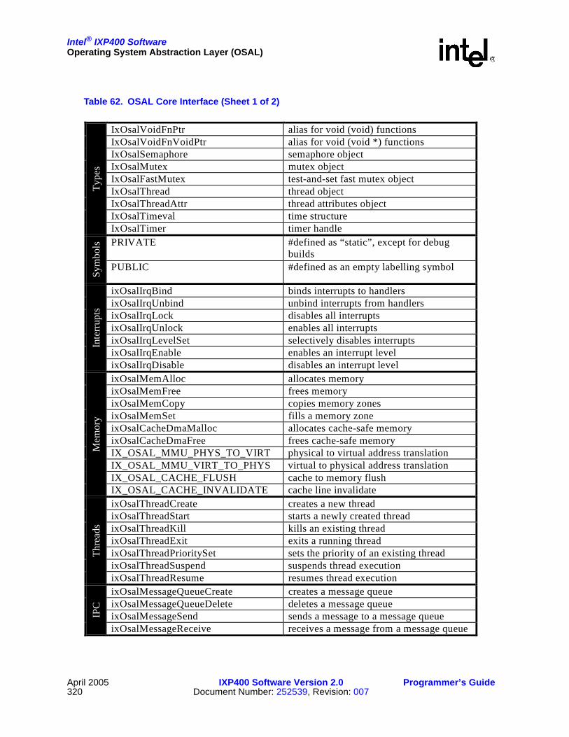
Intel® IXP400 SoftwareOperating System Abstraction Layer (OSAL)
April 2005 IXP400 Software Version 2.0 Programmer’s Guide320 Document Number: 252539, Revision: 007
Table 62. OSAL Core Interface (Sheet 1 of 2)
IxOsalVoidFnPtr alias for void (void) functions IxOsalVoidFnVoidPtr alias for void (void *) functions IxOsalSemaphore semaphore object IxOsalMutex mutex object IxOsalFastMutex test-and-set fast mutex object IxOsalThread thread object IxOsalThreadAttr thread attributes object IxOsalTimeval time structure
Type
s
IxOsalTimer timer handle PRIVATE #defined as “static”, except for debug
builds
Sym
bols
PUBLIC #defined as an empty labelling symbol
ixOsalIrqBind binds interrupts to handlers ixOsalIrqUnbind unbind interrupts from handlers ixOsalIrqLock disables all interrupts ixOsalIrqUnlock enables all interrupts ixOsalIrqLevelSet selectively disables interrupts ixOsalIrqEnable enables an interrupt level
Inte
rrup
ts
ixOsalIrqDisable disables an interrupt level ixOsalMemAlloc allocates memory ixOsalMemFree frees memory ixOsalMemCopy copies memory zones ixOsalMemSet fills a memory zone ixOsalCacheDmaMalloc allocates cache-safe memory ixOsalCacheDmaFree frees cache-safe memory IX_OSAL_MMU_PHYS_TO_VIRT physical to virtual address translation IX_OSAL_MMU_VIRT_TO_PHYS virtual to physical address translation IX_OSAL_CACHE_FLUSH cache to memory flush
Mem
ory
IX_OSAL_CACHE_INVALIDATE cache line invalidate ixOsalThreadCreate creates a new thread ixOsalThreadStart starts a newly created thread ixOsalThreadKill kills an existing thread ixOsalThreadExit exits a running thread ixOsalThreadPrioritySet sets the priority of an existing thread ixOsalThreadSuspend suspends thread execution
Thre
ads
ixOsalThreadResume resumes thread execution ixOsalMessageQueueCreate creates a message queue ixOsalMessageQueueDelete deletes a message queue ixOsalMessageSend sends a message to a message queue IP
C
ixOsalMessageReceive receives a message from a message queue
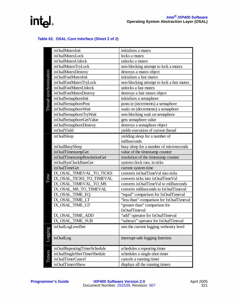
Intel® IXP400 SoftwareOperating System Abstraction Layer (OSAL)
Programmer’s Guide IXP400 Software Version 2.0 April 2005Document Number: 252539, Revision: 007 321
Table 62. OSAL Core Interface (Sheet 2 of 2)
ixOsalMutexInit initializes a mutex ixOsalMutexLock locks a mutex ixOsalMutexUnlock unlocks a mutex ixOsalMutexTryLock non-blocking attempt to lock a mutex ixOsalMutexDestroy destroys a mutex object ixOsalFastMutexInit initializes a fast mutex ixOsalFastMutexTryLock non-blocking attempt to lock a fast mutex ixOsalFastMutexUnlock unlocks a fast mutex ixOsalFastMutexDestroy destroys a fast mutex object ixOsalSemaphoreInit initializes a semaphore ixOsalSemaphorePost posts to (increments) a semaphore ixOsalSemaphoreWait waits on (decrements) a semaphore ixOsalSemaphoreTryWait non-blocking wait on semaphore ixOsalSemaphoreGetValue gets semaphore value ixOsalSemaphoreDestroy destroys a semaphore object
Thre
ad sy
nchr
oniz
atio
n
ixOsalYield yields execution of current thread ixOsalSleep yielding sleep for a number of
milliseconds ixOsalBusySleep busy sleep for a number of microseconds ixOsalTimestampGet value of the timestamp counter ixOsalTimestampResolutionGet resolution of the timestamp counter ixOsalSysClockRateGet system clock rate, in ticks ixOsalTimeGet current system time IX_OSAL_TIMEVAL_TO_TICKS converts ixOsalTimeVal into ticks IX_OSAL_TICKS_TO_TIMEVAL converts ticks into ixOsalTimeVal IX_OSAL_TIMEVAL_TO_MS converts ixOsalTimeVal to milliseconds IX_OSAL_MS_TO_TIMEVAL converts milliseconds to IxOsalTimeval IX_OSAL_TIME_EQ “equal” comparison for IxOsalTimeval IX_OSAL_TIME_LT “less than” comparison for IxOsalTimevalIX_OSAL_TIME_GT “greater than” comparison for
IxOsalTimeval IX_OSAL_TIME_ADD “add” operator for IxOsalTimeval
Tim
e
IX_OSAL_TIME_SUB “subtract” operator for IxOsalTimeval ixOsalLogLevelSet sets the current logging verbosity level
Logg
ing
ixOsalLog interrupt-safe logging function
ixOsalRepeatingTimerSchedule schedules a repeating timer ixOsalSingleShotTimerShedule schedules a single-shot timer ixOsalTimerCancel cancels a running timer Ti
mer
s
ixOsalTimersShow displays all the running timers

Intel® IXP400 SoftwareOperating System Abstraction Layer (OSAL)
April 2005 IXP400 Software Version 2.0 Programmer’s Guide322 Document Number: 252539, Revision: 007
24.6.2 Buffer Management ModuleThis module defines a memory buffer structure and functions for creating and managing buffer pools.
Table 63 provides an overview of the buffer management module.
24.6.3 I/O Memory and Endianness Support ModuleThe OSAL I/O Memory Management and Endianness Support Module implements:
• I/O memory management
• Big and little endian support
I/O memory management defines a set of macros allowing the user to gain and release access to memory-mapped I/O in an operating-system-independent fashion. Depending on the target platform and OS, gaining access can vary between statically mapped I/O to dynamically mapped I/O through OS-specific functions (for example, ioremap() in Linux).
Using a global memory map, which defines the specifics of each memory map cell (for example, UART registers), the access of I/O memory can be abstracted independent of operating systems, dynamic mapping, or endianness-dependent virtual memory locations. This functionality makes the code far more portable across different operating systems and platforms.
Wind River* VxWorks OS maintains a 1:1 virtual to physical mapping. However, this is not the case in other OS such as Linux . The OSAL layer provides a portable approach that involves mapping the memory when the software is initialized to access the desired memory and unmapping the memory when the software unloads. Depending upon the build for a particular OS (and if the memory is not statically mapped), the OSAL can create MMU entries to map the specified physical address in the usable memory range.
Additionally, the mapping automatically considers the endianness type in systems that can use mixed endian modes (such as the IXP4XX product line and IXC1100 control plane processors). This behavior is controlled by two defines which have to be supplied by the software using these methods: IX__OSAL_COMPONENT_MAPPING and IX_OSAL_MEM_MAP_TYPE.
Table 63. OSAL Buffer Management Interface
IX_OSAL_MBUF memory buffer
Type
s
IX_OSAL_MBUF_POOL memory buffer pool
ixOsalPoolInit initializes pool with memory allocation ixOsalNoAllocPoolInit initializes pool without memory allocation ixOsalMbufAlloc allocates a buffer from a pool ixOsalMbufFree frees a buffer into its pool ixOsalMbufChainFree frees a buffer chain into its pool ixOsalMbufDataPtrReset resets the buffer data pointer
Func
tions
ixOsalPoolShow displays pool statistics

Intel® IXP400 SoftwareOperating System Abstraction Layer (OSAL)
Programmer’s Guide IXP400 Software Version 2.0 April 2005Document Number: 252539, Revision: 007 323
The OSAL layer also provides APIs for dealing with the following situations:
• Transparently accessing I/O-memory-mapped hardware in different endian modes
• Transparently accessing SDRAM memory between any endian type and big endian, for the purpose of sharing data with big-endian auxiliary processing engines
The OSAL layer supports the following endianness modes:
• Big endian
• Little endian
• Little endian address coherent where
— Core is operating in little endian mode but the bus addresses are swapped
— 32-bit word accesses are made automatically in big endian mode
— Byte and 16-bit half-word addresses are swapped (address XOR 3)
• Little endian, data coherent where,
— Core is operating in little endian mode but the bus data is swapped
— Byte accesses are made automatically in big endian mode
— 32-bit word and 16-bit half-word values are swapped
In little endian mode, users must specify coherency modes before using the IO/Memory access macros (for example, IX_OSAL_READ_LONG, IX_OSAL_WRITE_LONG). This can be performed by declaring Little Endian Coherency mode in the customized mapping declarations under os/vxworks/include/platforms/ixp400/.
Table 64 provides an overview of the I/O memory and endianness support module.
Table 64. OSAL I/O Memory and Endianness Interface (Sheet 1 of 2)
IX_OSAL_COMPONENT_MAPPING select endianness mapping type IX_OSAL_MEM_MAP_TYPE select static/dynamic I/O mapping
Def
ines
re
quire
d
IX_OSAL_SDRAM_ENDIANNESS select SDRAM endianness
IX_OSAL_MEM_MAP map I/O memory IX_OSAL_MEM_UNMAP unmap I/O memory IX_OSAL_MMAP_PHYS_TO_VIRT physical to virtual translation I/O
M
appi
ng
IX_OSAL_MMAP_VIRT_TO_PHYS virtual to physical translation

Intel® IXP400 SoftwareOperating System Abstraction Layer (OSAL)
April 2005 IXP400 Software Version 2.0 Programmer’s Guide324 Document Number: 252539, Revision: 007
24.7 Supporting a New OSSupport for a new operating system can be added separately by creating a new OS-specific folder under the “os” directory, with necessary modification to the core module and the build system to expand the supported OS list. It is not required that a new OS be supported for all the OSAL modules. Similarly, it is not required that supporting a new OS extends to the entire API within a module. For example, the new OS might not support locking via mutexes or semaphores.
To preserve the modularity, it is recommended that any API implementation that can be reused for another OS, and that exists in an OS-specific directory, be moved into the shared directory for the other operating system.
Each software component using the OSAL I/O memory mapping and endianness support module must define the following symbols:
• IX_OSAL_MEM_MAP_TYPE
This selects dynamic (IX_OSAL_DYNAMIC_MEM_MAP) or static (IX_OSAL_STATIC_MEM_MAP) memory mapping (required for the IX_OSAL_READ/WRITE macros) used by the software component.
Table 64. OSAL I/O Memory and Endianness Interface (Sheet 2 of 2)
IX_OSAL_SWAP_LONG 32-bit word byte swap IX_OSAL_SWAP_SHORT 16-bit short byte swap IX_OSAL_SWAP_SHORT_ADDR 16-bit short address swap
IX_OSAL_SWAP_BYTE_ADDR byte address swap
IX_OSAL_READ_BYTE I/O byte read IX_OSAL_WRITE_BYTE I/O byte write IX_OSAL_READ_SHORT I/O 16-bit short read IX_OSAL_WRITE_SHORT I/O 16-bit short write IX_OSAL_READ_LONG I/O 32-bit word read
I/O R
ead/
Writ
e
IX_OSAL_WRITE_LONG I/O 32-bit word write IX_OSAL_WRITE_BE_SHARED_BYTE big endian byte write IX_OSAL_WRITE_BE_SHARED_SHORT
big endian 16-bit short write
IX_OSAL_WRITE_BE_SHARED_LONG big endian 32-bit word write IX_OSAL_READ_BE_SHARED_BYTE big endian byte read IX_OSAL_READ_BE_SHARED_SHORT big endian 16-bit short read IX_OSAL_READ_BE_SHARED_LONG big endian 32-bit word read IX_OSAL_SWAP_BE_SHARED_SHORT big endian 16-bit short swap IX_OSAL_SWAP_BE_SHARED_LONG big endian 32-bit word swap M
ixed
end
ian
syst
ems
IX_OSAL_COPY_BE_SHARED_LONG_ARRAY
big endian 32-bit word array copy
Intel® IXP400 SoftwareOperating System Abstraction Layer (OSAL)
Programmer’s Guide IXP400 Software Version 2.0 April 2005Document Number: 252539, Revision: 007 325
• IX_OSAL_IO_ENDIANESS
This selects the I/O endianness type required by the component. This can be:
— Big endian (IX_OSAL_BE)
— Little endian (IX_OSAL_LE). In this mode users cannot access IoMem macros such as IX_OSAL_READ_LONG, IX_OSAL_WRITE_LONG, etc., and must declare coherency mode before using them; see Section 24.8.
— Little endian, address coherent (IX_OSAL_LE_AC)
— Little endian, data coherent (IX_OSAL_LE_DC)
• IX_OSAL_SDRAM_ENDIANESS
This selects the SDRAM endianness used in the component. This can be:
— Big endian (IX_SDRAM_BE)
— Little endian (IX_SDRAM_LE)
— Little endian, address coherent (IX_SDRAM_LE_ADDRESS_COHERENT)
— Little endian, data coherent (IX_SDRAM_LE_DATA_COHERENT)
It is recommended to use a unique identifier for each software component, known at build time, and define these symbols in only one file for each component.
24.8 Supporting New PlatformsEach platform implementing the I/O memory mapping and endianness support module is required to define a global memory map array, each element in the array having the IxOsalMemMap type. Typically each contiguous range in the platform memory map is represented by an entry in the global memory map. To support operating systems using dynamic memory mapping, custom functions for mapping and un-mapping memory must be implemented. These functions have already been implemented for Linux
Note: Platform specific refers to all the platforms using the same network processor variants. The IXP4XX product line and IXC1100 control plane processorsare all part of the same platform in this case. A change in product line refers to using the OSAL layer for a new platform.
The platform package must also include the definition for the global memory map using the IX_OSAL_IO_MEM_GLOBAL_MEMORY_MAP define, as in the following example:
#define IX_OSAL_IO_MEM_GLOBAL_MEMORY_MAP ixp123GlobalMemoryMap
The following is an example fragment of a global memory map:
Example 1. Global Memory Map Definitions
IxOsalMemoryMap ixp123GlobalMemoryMap[] =#ifdef IX_OSAL_LINUX
/* PCI config Registers */

Intel® IXP400 SoftwareOperating System Abstraction Layer (OSAL)
April 2005 IXP400 Software Version 2.0 Programmer’s Guide326 Document Number: 252539, Revision: 007
IX_STATIC_MAP, /* type */ IXP123_PCI_CFG_BASE_PHYS, /* physicalAddress */ IXP123_PCI_CFG_REGION_SIZE, /* size */ IXP123_PCI_CFG_BASE_VIRT, /* virtualAddress */ NULL, /* mapFunction */ NULL, /* unmapFunction */ 0, /* refCount */ IX_OSAL_BE, /* coherency */ "pciConfig" /* name */ ,#elif defined IX_OSAL_VXWORKS /* Global 1:1 big endian and little endian, address coherent map */ IX_STATIC_MAP, /* type */ 0x00000000, /* physicalAddress */ 0xFFFFFFFF, /* size */ 0x00000000, /* virtualAddress */ NULL, /* mapFunction */ NULL, /* unmapFunction */ 0, /* refCount */ IX_OSAL_BE | IX_OSAL_LE_AC, /* coherency */ "global" /* name */ #endif
Note: “|” stands for “or”.
Note: The definition of the memory map is very flexible in terms of what operating systems and endianness modes can share memory map cells. Typically, an OS would use only one memory map and share the same cells for big endian and little endian access types. This is exemplified above by setting the access coherency to composite types such as “IX_OSAL_BE or IX_OSAL_LE_AC”, which means the cell can be used for big endian and little endian/address coherent access. It is, however, not possible to share a cell between both little endian address coherent and data coherent, as these are fundamentally conflicting modes of operation.

Intel® IXP400 Software
Programmer’s Guide IXP400 Software Version 2.0 April 2005Document Number: 252539, Revision: 007 327
ADSL Driver 25
This chapter describes the ADSL driver for the Intel® IXDP425 / IXCDP1100 Development Platform and Intel® IXDP465 Development Platform that supports the STMicroelectronics* (formally Alcatel*) MTK-20150 ADSL chipset in the ADSL Termination Unit-Remote (ATU-R) mode of operation.
The ADSL driver is provided as a separate package along with the Intel® IXP400 Software v2.0.
25.1 What’s NewThere are no changes or enhancements to this component in software release 2.0.
25.2 Device SupportSTMicroelectronics MTK-20150 on the IXDP425 / IXCDP1100 platform. The MTK-20150 chipset is made up of MTC-20154 integrated analog front end and the MTC-20156 DMT/ATM digital modem and ADSL transceiver controller.
25.3 ADSL Driver OverviewThe two main interfaces to the ADSL chipset are:
• The parallel CTRL-E interface — via the processor’s expansion bus
• The ATM UTOPIA data path interface — via the processor’s UTOPIA interface
The ADSL driver only supports communication with the ADSL chipset via the CTRL-E interface. All data path communication (ATM UTOPIA) must be performed via the ATM Access Layer component of the IXP400 software.
The driver uses the CTRL-E interface to download the STMicroelectronics firmware, configure and monitor the status of the ADSL chipset. The advantage of downloading the firmware via the CTRL-E interface is that it removes the requirement for a separate flash for the STMicroelectronics ADSL chipset.
The driver provides an API to bring the ADSL line up in ATU-R mode. The line is configured to negotiate the best possible line rate, given the conditions of the local loop when the line is opened. The line rate is not renegotiated once the modems are in the “show-time” mode.
There is very little configuration information required to open an ATU-R line. Almost all line configuration parameters are supplied by the ATU-C side.
APIs are provided to take the modem off line and to check the state of the line to see if the modem is in “show-time” mode.

Intel® IXP400 SoftwareADSL Driver
April 2005 IXP400 Software Version 2.0 Programmer’s Guide328 Document Number: 252539, Revision: 007
25.3.1 Controlling STMicroelectronics* ADSL Modem Chipset Through CTRL-EThe STMicroelectronics ADSL chipset CTRL-E interface is memory-mapped into the processor’s expansion bus address space. Figure 107 shows how the chipset is connected to the processor.
The CTRL-E interface is used for all non-data-path communication between the processor and the ADSL chipset. The ADSL driver public APIs use private driver utilities to convert client requests into CTRL-E commands to the ADSL chipset.
25.4 ADSL APIThe ADSL driver provides a number of API that provide several general types of functionality. APIs are provided in the following areas:
• Firmware download to the ADSL chipset
• Initialization of the ADSL devices
• Opening, closing and monitoring an ADSL line.
• Soft reset
25.5 ADSL Line Open/Close OverviewNote: Before calling the ADSL driver line open function the ATM Access Layer must be started.
Figure 108 on page 329 provides an example of the ADSL driver functions that the client application code will call to open an ADSL line.
Figure 107. STMicroelectronics* ADSL Chipset on the Intel® IXDP425 / IXCDP1100 Development Platform
16-Mbyte Flash
Intel® IXP425Network Processor
STMicroelectronics* ADSLModem Chipset
UTOPIA
RJ11 ADSL-ReadyPort
CTRL-E
ExpansionBus
B2423-01

Intel® IXP400 SoftwareADSL Driver
Programmer’s Guide IXP400 Software Version 2.0 April 2005Document Number: 252539, Revision: 007 329
Step 1 of Figure 108 is only required if the client application wants to be notified when a line state changes occurs.
Step 2 of Figure 108 is called by the client application to establish an ATU-R ADSL connection with another modem. This function call performs the following actions within the private context of the ADSL driver:
a. Invokes the private ixAdslDriverInit function which creates an ixAdslLineSupervisoryTask. This task invokes the ixAdslLineStateMachine.
b. Invokes the private ixAdslUtilDeviceDownload function which downloads the STMicroelec-tronics* ADSL firmware and configures the chipset.
c. Invokes the private ixAdslCtrleEnableModem function which enables the ADSL chipset to start opening the line.
The client application can close an ADSL line by calling the ixAdslLineClose( ) API which will disable the modem (i.e. close the line) but not kill the ixAdslLineSupervisoryTask.
Figure 108. Example of ADSL Line Open Call Sequence
ADSL ClientLine Open
1. ixAdslLineStateChangeCallbackRegister (lineNum, lineChangeCallbackFn)
2. ixAdslLineOpen (lineNum, lineType, phyType)
ADSL Driver
ADSLChipset
B2404-01

Intel® IXP400 SoftwareADSL Driver
April 2005 IXP400 Software Version 2.0 Programmer’s Guide330 Document Number: 252539, Revision: 007
25.6 Limitations and Constraints• The driver only supports the ATU-R mode of operation.
• The driver can operate in single PHY mode only.

Intel® IXP400 Software
Programmer’s Guide IXP400 Software Version 2.0 April 2005Document Number: 252539, Revision: 007 331
I2C Driver (IxI2cDrv) 26
This chapter describes the I2C Driver provided with Intel® IXP400 Software v2.0, which is for use with the Intel® IXP46X Product Line of Network Processors.
26.1 What’s NewThis is a new component for software release 2.0.
26.2 IntroductionThe IXP46X network processors include an I2C hardware interface. This I2C driver is provided to configure and enable I2C hardware and provide a mechanism for transferring data serially through the I2C bus in both master and slave mode. Four methods of data transfer are supported by the driver: single-byte read, multi-byte read, single-byte write, and multi-byte write. The driver allows the addressing to any I2C Slave on the bus.
The capability to enable/disable the response to I2C slave address and general address calls is also provided. Transaction records/counters between the I2C hardware and other devices are tracked by the driver. The driver provides the capability to scan the bus to detect I2C slave devices and supports multiple I2C bus masters.
The driver is implemented in what is referred to as the "Algorithm Module". This module performs the configuration and control of data transfers. This component is supported on both VxWorks and Linux.
The driver interface is compatible with the standard Linux I2C device driver, and is provided separately from the IXP400 software access-layer. Since Linux does not allow direct user mode access to kernel driver functions, a separate “Adapter Module” is provided to accommodate direct access from user mode.
26.3 I2C Driver API Details
26.3.1 Features
The I2C driver allows the setting of different configurations for the I2C hardware, as listed below:
• Mode select – fast mode (400 kbps) or normal mode (100 kbps). High Speed (3.4 Mbps) mode is not supported by hardware.
• Flow Selection - Interrupt or Polling modes
• Enable/disable I2C unit response to general calls
• Enable/disable I2C unit response to slave address calls

Intel® IXP400 SoftwareI2C Driver (IxI2cDrv)
April 2005 IXP400 Software Version 2.0 Programmer’s Guide332 Document Number: 252539, Revision: 007
• Enable/disable the driving of the SCL line
• I2C slave address of the processor
The I2C driver features the following hardware and bus status items:
• Master transfer error
• Bus error detected
• Slave address detected
• General call address detected
• IDBR receive full
• IDBR transmit empty
• Arbitration loss detected
• Slave STOP detected
• I2C bus busy
• I2C unit busy
• Received/sent status for ACK/NACK
• Read/write mode (master-transmit/slave-receive or master-receive/slave-transmit)
• Selectable use of internal or OS-provided delay functions.
The I2C driver supports single and multi read, single and multi write, and repeated start data transfers for both interrupt and polled mode. A repeated start data transfer is when the master sends a start instead of a stop-start to initiate the next transfer. It is different from a multi read or multi write in that it can allow a read followed by a write or vice versa. Repeated start data transfers in slave mode are not supported.
The I2C hardware does not support extended 10-bit I2C addressing; only 7-bit slave addressing is supported. The driver will allow any 7-bit slave address (0x01 to 0x7F) except 0x00, which is reserved for general calls.
26.3.2 DependenciesThe I2C driver is dependent on the capability provided by the I2C hardware. Also, the driver is dependant upon IxOSAL to provide OS independency. The adapter module provides the Linux driver interface between the user-space applications and the kernel-space adapter module of the I2C driver. Therefore the adapter module is dependent on the I2C algorithm module. VxWorks uses the I2C driver directly and does not need an adapter module.

Intel® IXP400 SoftwareI2C Driver (IxI2cDrv)
Programmer’s Guide IXP400 Software Version 2.0 April 2005Document Number: 252539, Revision: 007 333
26.3.3 Error HandlingThe I2C driver is capable of detecting all errors that the I2C hardware is able to provide as listed below:
• Arbitration loss error
• Bus error
Any errors that occur during data transfer which do not fall into the arbitration loss or bus error categories will be classified as a master transfer error (IX_I2C_MASTER_XFER_ERROR).
26.3.3.1 Arbitration Loss Error
This error occurs when the I2C hardware of the IXP46X network processors loses master control while it is acting as master. Arbitration loss happens when the unit as master sends a high signal but another master sends a low. The occurrence of two masters on the bus can happen when one I2C unit does not see another I2C unit’s START signal to take master of the bus and then sends it own START signal to take master of the bus. Such an occurrence can happen when an I2C unit just exited reset and has no history of previous signals. When this occurs, the I2C status register will be updated with the arbitration loss by the hardware, and if the interrupt for arbitration loss is enabled, then it will call the interrupt service routine.
Figure 109. I2C Driver Dependencies
B4374-01
Access-Layer Interface
Hardware Interface
Client Application
IxOSALI2C Driver(Algorithm Module )
I2C Interface
I2C Adapter Module
VxW
orks
* Linux*

Intel® IXP400 SoftwareI2C Driver (IxI2cDrv)
April 2005 IXP400 Software Version 2.0 Programmer’s Guide334 Document Number: 252539, Revision: 007
Once an arbitration loss error is detected, the unit will stop transmitting. The client will need to call the transfer again and the I2C status register will be checked to determine the busy status of the I2C bus. If the bus is not busy, the transfer that occurred before the bus arbitration loss error will be re-submitted.
26.3.3.2 Bus Error
This error occurs when the I2C unit, as a master transmitter, does not receive an ACK in response to transmission. A bus error can also occur when the I2C unit is operating as a slave receiver, and a NACK pulse is generated. In master transmit mode, the hardware will abort the transaction by automatically sending a STOP signal. As a slave receiver, the behavior will depend on the master’s action. The counters for both occurrences will be updated accordingly.
26.4 I2C Driver API Usage Models
26.4.1 Initialization and General Data ModelThis description assumes a single client model where there is a single application-level program configuring the I2C interface and initiating I/O operations.
Initialization
The client must first define the initial configuration of the I2C port by storing a number of values in the IxI2cInitVars structure. The values include the speed selection, data flow mode, pointers to callback functions for various data scenarios, hardware address, and behavior settings for how the I2C unit responds to general call and slave address calls. After the structure is defined, ixI2cDrvInit() may be called to enable the port.
Once the port is enabled, the client will use one of the data models described later in this chapter (either Interrupt or Polling mode) to determine how and when data I/O operations need to occur.
A callback or handler may be registered for interrupt transmit and receive operations in the IxI2cInitVars structure. There are different callbacks for when the I2C unit is operating in master or slave mode, and also for general calls.
Master-Interrupt Mode
The client will use the ixI2cDrvWriteTransfer() and ixI2cDrvReadTransfer() functions for transmitting and receiving data on the I2C bus in master mode. The functions will return immediately, even though the transfer has not completed. Upon function return, the callback routines registered in IxI2cInitVars will be executed. The I2C unit will handle the appropriate arbitration and bus messaging required to support the transfer type and mode.
While the I2C unit is in Master-Interrupt mode, the use of interrupt callbacks is optional. If no callbacks are registered, the read/write transfer functions discussed above will wait until the transfer operation has completed before returning to the calling application. This method can be used if transfer status information is not needed for each transaction and simplifies the implementation of repeated start transfers. The data that is passed in the callback includes transfer mode, buffer pointer and buffer size. Since this data is already known to the client application, processing of this data via the callback would be inefficient.

Intel® IXP400 SoftwareI2C Driver (IxI2cDrv)
Programmer’s Guide IXP400 Software Version 2.0 April 2005Document Number: 252539, Revision: 007 335
Slave-Interrupt Mode
When the processor is acting in I2C slave mode or responding to general calls in interrupt mode, the client callbacks for transmit and receive are responsible for providing a buffer used to interface with the I2C Data Buffer Register (IDBR), using the ixI2cDrvSlaveOrGenCallBufReplenish() function.
Examples of Slave Interrupt mode operations is provided in “Example Sequence Flows for Slave Mode” on page 336.
Slave-Polling Mode
In polling mode, the client polling task can check for pending requests to respond to slave request or general calls using the ixI2cDrvSlaveAddrAndGenCallDetectedCheck() function. The client can then use the ixI2cDrvSlaveOrGenDataReceive() or ixI2cDrvSlaveOrGenDataTransmit() functions to transfer data.
Support Functions
After the I2C unit has been initialized as described above, there are several supporting functions available in the API. These include functions that set the 7-bit Slave address to which the I2C Unit responds, scan the I2C bus for slave units, check or reset port statistics, and show the current status of the I2C unit and driver. The API can also uninitialize the I2C unit and remove the driver from memory.
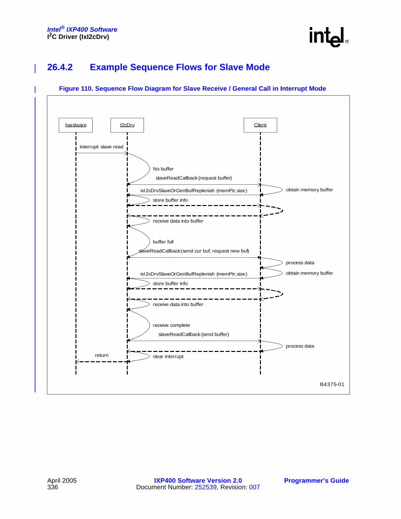
Intel® IXP400 SoftwareI2C Driver (IxI2cDrv)
April 2005 IXP400 Software Version 2.0 Programmer’s Guide336 Document Number: 252539, Revision: 007
26.4.2 Example Sequence Flows for Slave Mode
Figure 110. Sequence Flow Diagram for Slave Receive / General Call in Interrupt Mode
B4375-01
I2cDrvhardware
interrupt: slave read
Client
slaveReadCallback (request buffer)
ixI2cDrvSlaveOrGenBufReplenish (memPtr,size)
store buffer info
receive data into buffer
slaveReadCallback(send cur buf, request new buf)
No buffer
process data
ixI2cDrvSlaveOrGenBufReplenish (memPtr,size)
buffer full
store buffer info
receive data into buffer
receive complete
process data
return
slaveReadCallback (send buffer)
obtain memory buffer
obtain memory buffer
clear interrupt

Intel® IXP400 SoftwareI2C Driver (IxI2cDrv)
Programmer’s Guide IXP400 Software Version 2.0 April 2005Document Number: 252539, Revision: 007 337
Figure 111. Sequence Flow Diagram for Slave Transmit in Interrupt Mode
B4376-01
I2cDrvhardware
interrupt: slave write
client
transmit data from buffer
No buffer
buffer empty
transmit complete
return memory
obtain memory buffer
store data into bufferixI2cDrvSlaveOrGenBufReplenish (memPtr,size)
store buffer info
reuse buffer
store data into buffer
transmit data from buffer
ixI2cDrvSlaveOrGenBufReplenish (memPtr,size)
store buffer info
slaveWriteCallback (send cur buf, request new buf)
slaveWriteCallback (request buf)
slaveWriteCallback (send buf)
return clear interrupt

Intel® IXP400 SoftwareI2C Driver (IxI2cDrv)
April 2005 IXP400 Software Version 2.0 Programmer’s Guide338 Document Number: 252539, Revision: 007
Figure 112. Sequence Flow Diagram for Slave Receive in Polling Mode
B4377-01
client i2cDrv
ixI2cDrvSlaveAddrAndGenCallDetectedCheck
Check Slave Addr DetectedIX_I2C_SLAVE_ADDR_NOT_DETECTED
ixI2cDrvSlaveAddrAndGenCallDetectedCheck
Check Slave Addr DetectedIX_I2C_SLAVE_READ_DETECTED
ixI2cDrvSlaveOrGenDataReceive (first buf)
receive dataIX_I2C_SLAVE_OR_GEN_READ_BUFFER_FULL
ixI2cDrvSlaveOrGenDataReceive (second buf)
receive dataIX_I2C_SUCCESS
receive all data, process data

Intel® IXP400 SoftwareI2C Driver (IxI2cDrv)
Programmer’s Guide IXP400 Software Version 2.0 April 2005Document Number: 252539, Revision: 007 339
26.4.3 I2C Using GPIO Versus Dedicated I2C HardwareSome supported operating systems include support for emulating the I2C bus using GPIO lines on the processor.
The I2C driver using a dedicated I2C hardware is a totally different implementation from the driver using GPIO lines. Most of the APIs in a driver using a GPIO implementation are very low level (dedicated to controlling the SDA and SCL lines) and combine to make one transaction. The driver APIs using dedicated I2C hardware (such as with IxI2cDrv) will be limited to the control provided by the hardware unit on the processor. Furthermore, the dedicated I2C hardware implementation allows more advanced features supported by the hardware, such as those to support multi-master on the bus, therefore allowing the IXP46X network processors to act as slave devices.
Figure 113. Sequence Flow Diagram for Slave Transmit in Polling Mode
B4378-01
client i2cDrv
ixI2cDrvSlaveAddrAndGenCallDetectedCheck
Check Slave Addr DetectedIX_I2C_SLAVE_ADDR_NOT_DETECTED
ixI2cDrvSlaveAddrAndGenCallDetectedCheck
Check Slave Addr DetectedIX_I2C_SLAVE_WRITE_DETECTED
store data into first buf
ixI2cDrvSlaveDataTransmit (first buf)
transmit dataIX_I2C_SLAVE_WRITE_BUFFER_EMPTY
store data into second buf
ixI2cDrvSlaveOrGenDataReceive (second buf)
transmit dataIX_I2C_SUCCESS

This page is intentionally left blank.
Intel® IXP400 Software
April 2005 IXP400 Software Version 2.0 Programmer’s Guide340 Document Number: 252539, Revision: 007

Intel® IXP400 SoftwareEndianness in Intel® IXP400 Software
Programmer’s Guide IXP400 Software Version 2.0 April 2005Document Number: 252539, Revision: 007 341
Endianness in Intel® IXP400 Software 27
27.1 OverviewThe Intel® IXP4XX Product Line of Network Processors and IXC1100 Control Plane Processor support Little-Endian (LE) and Big-Endian (BE) operations. This chapter discusses IXP400 software support for LE and BE operation.
This chapter is intended for software engineers developing software or board-support packages (BSPs) that are reliant on endianness support in the processor. The chapter is intended as an introduction to the most important facts regarding endianness as it relates to the IXP400 software.
A more detailed guide to endianness in the IXP42X product line is available in the application note, Intel® IXP42X Product Line of Network Processors and IXC1100 Control Plane Processor: Understanding Big Endian and Little Endian Modes, which is freely available from the following Intel Developer Web site:
http://www.intel.com/design/network/products/npfamily/docs/ixp4xx.htm
Applicability to Specific Processors and Development Platforms
In general, the theories discuss in this chapter are applicable the entire IXP4XX product line. Each product generation does have some specific endianness related capabilities, as listed in “Silicon Versions” on page 352.
When discussing board-support package (BSP) issues for the Intel® IXP42X Product Line of Network Processors and IXC1100 Control Plane Processor, this chapter refers to the Intel® IXDP425 / IXCDP1100 Development Platform. For the Intel® IXP46X Product Line of Network Processors, this chapter refers to the Intel® IXDPG465 Network Gateway Development Platform.
27.2 The Basics of EndiannessEndianness is the numbering organization format of data representation in a computer. Endianness comes in two varieties: Big and Little. Little-Endian byte ordering assigns the lower byte address to the low eight bits of a 32-bit memory word, where Big-Endian byte order is the opposite. LE means that the least-significant byte of any multi-byte data field is stored at the lowest memory address, which is also the address of the larger field. See Figure 114.
All processors are either Big- or Little-Endian. Some processors, such as those in the IXP4XX product line and IXC1100 control plane processors, have a bit in a register that allows the programmer to select the desired endianness.

Intel® IXP400 SoftwareEndianness in Intel® IXP400 Software
April 2005 IXP400 Software Version 2.0 Programmer’s Guide342 Document Number: 252539, Revision: 007
It should also be noted that endianness only applies when byte and half-word accesses are made to memory. If a 32-bit word is read or written to memory, the bit pattern in the memory always matches the bit pattern in the processor register, regardless of the endianness of the system.
27.2.1 The Nature of Endianness: Hardware or Software?A processor may be capable of supporting both LE and BE with the active form of endianness being dependent on bus behavior and the memory systems connected to that bus. Only correct matching between the processor’s mode, bus mode (that is, how the bus and memory are connected), and the software will provide correct endian behavior.
Endianness is, in general, a hardware and software issue. However, a processor does not operate in a vacuum. It is part of a system. This implies that a hardware board with processors and memory components (unless specially designed to support both endians) would only support one endian mode, and software on any processor in the system must work with that same endian mode.
27.2.2 Endianness When Memory is SharedFollowing the definition of endianness from a software point of view, and assuming a piece of hardware can be extremely complex and intelligent, can a piece of memory being shared by two processors running under different endian modes achieve all “IDEAL_BI_ENDIAN” objectives at the same time? The objectives for such a system are as follows:
• Share long integers correctly. “Correctly” could be defined as one processor ‘feeling’ that the other processor is under the same endianness mode as itself. For example, ProcessorBig writes some data starting from it’s view of address X. Then, if ProcessorLittle reads the same amount of data starting from its own view of address X, the data read is the same as the data written by ProcessorBig.
• Share short integers correctly.
• Share byte integers correctly.
• Each processor has its own endianness consistency.
Figure 114. 32-Bit Formats
Byte 3 Byte 2 Byte 1 Byte 0
031
Memory0x00
32-bit Little-endian memory
Byte 0 Byte 1 Byte 2 Byte 3
031
Memory0x00
32-bit Big-endian memory

Intel® IXP400 SoftwareEndianness in Intel® IXP400 Software
Programmer’s Guide IXP400 Software Version 2.0 April 2005Document Number: 252539, Revision: 007 343
Unfortunately, the answer is NO even with help from the most sophisticated hardware.
27.3 Software Considerations and ImplicationsMuch literature is available explaining the software dependency on underlying hardware endianness.
In summary, software dependency on hardware endianness is manifested in these areas:
• Whenever a piece of software accesses a piece of memory which is treated as different sizes by manipulation of pointers in different parts of code, that code is endian-dependent. For example, IP address 0x01020304 can be treated as unsigned long. But if code needs to access byte 0x04 by manipulating pointers, the code becomes endian-dependent.
• If a piece of memory is accessed by other hardware or processors whose endian modes are independent of the processor on which the current software is running, then the current code becomes endian-dependent. For example, network data is always assumed to be Big-Endian. If network data is directly moved (DMA’ed) into memory as it is, then that particular piece of memory is always Big-Endian. As a result, the current code accessing that piece of memory becomes endian-dependent. If pointers are passed between processors, endian issues show immediately because of the fundamental difficulty, as explained in “The Nature of Endianness: Hardware or Software?” on page 342.
• The above issues can occur in many places of an operating system, a hardware driver, or even a piece of application code. Some operating systems (for example, VxWorks*) support both endians by different compilation switches.
• Compiler, debugger, and other tools are generally endian-dependent because the translation between a high-level language (for example, C) and assembly language is endian-dependent.
Under certain application assumptions, and when programming carefully, it is possible to have a piece of code that is endian-independent.
27.3.1 Coding Pitfalls — Little-Endian/Big-EndianThe risks associated with programming in mixed endian system generally revolve around possible incompatibilities in the interpretation of data between Little-Endian and Big-Endian components within the system. The following examples illustrate some instances where pitfalls in coding can be interpreted differently on LE versus BE machines (and thus should be avoided). There are also examples of how to code a module in a way that permits a consistent interpretation of data structures and data accesses in general, regardless of the endianness of the processor the code may be running on. Performance can also enter into the equation, especially if byte order needs to be frequently shuffled by the processor.
27.3.1.1 Casting a Pointer Between Types of Different Sizes
The situation that this example illustrates needs to be avoided completely. Do not mix pointer sizes. Endianness causes different interpretation from one machine to the next, making porting problematic.
int J=8;char c = *(char *) J;
Depending on the endianness of the processor the code is executing on, the result is:

Intel® IXP400 SoftwareEndianness in Intel® IXP400 Software
April 2005 IXP400 Software Version 2.0 Programmer’s Guide344 Document Number: 252539, Revision: 007
Little:0x8 Big:0x0
The following provides another example of endianness causing the code to be interpreted differently on BE versus LE machines:
int myString[2] = 0x61626364,0; /* hex values for ascii */Printf(“%s\n”, (char *)&myString);
Depending on the endianness of the processor the code is executing on, the result is: Little:“dcba”Big:“abcd”
27.3.1.2 Network Stacks and Protocols
Little-Endian Machines: Running a network protocol stack on a Little-Endian processor can degrade performance due to formatting translation. If a network protocol stack is to be run on a Little-Endian processor, at run time it will have to reorder the bytes of every multi-byte data field within the various layers' headers.
Big-Endian Machines: Running a network protocol stack on a Big-Endian processor does not degrade performance due to formatting translation. If the stack will run on a Big-Endian processor, there is nothing to worry about; the endianness of the processor inherently matches the format of standard network data ordering.
27.3.1.3 Shared Data Example: LE Re-Ordering Data for BE Network Traffic
By using a macro conversion routine, the data access is re-ordered as needed to properly interpret data moving between a network (which is using Big-Endian or network order) and a host machine, which may be Little-Endian.
Basic Assumptions:
• TCP/IP defines the network byte order as Big-Endian.
• Little-Endian machines must byte swap accesses to 16-/32-bit data types (IP address, checksum, etc.).
Example: We want to assign the value of the IP source address field in the header of an IP packet to a 32-bit value we will call “src.” Here is the code, which features a macro to translate.
u_long src = ntohl(ip->ip_src.s_addr);
Here is what the macro ntohl() looks like in actual code:–ntohl()#if (_BYTE_ORDER == _BIG_ENDIAN)
#define ntohl(x) (x)
#else#define ntohl(x)((((x) & 0x000000ff) << 24) | \
(((x) & 0x0000ff00) << 8) | \(((x) & 0x00ff0000) >> 8) | \(((x) & 0xff000000) >> 24))
#endif

Intel® IXP400 SoftwareEndianness in Intel® IXP400 Software
Programmer’s Guide IXP400 Software Version 2.0 April 2005Document Number: 252539, Revision: 007 345
We always assume that the byte order value will be set to either Big-Endian or Little-Endian in a define value.
27.3.2 Best Practices in Coding of Endian-IndependenceAvoid
• Code that assumes the ordering of data types in memory.
• Casting between different-sized types.
Do• Perform any endian-sensitive data accesses in macros. If the machine is Big-Endian, the
macros will not have a performance hit. A Little-Endian machine will interpret the data correctly.
27.3.3 Macro Examples: Endian ConversionA common solution to the endianness conversion problem associated with networking is to define a set of four preprocessor macros: htons(), htonl(), ntohs(), and ntohl(). These macros make the following conversions:
htons(): The macro name can be read “host to network short.”
reorder the bytes of a 16-bit value from processor order to network order.
htonl(): The macro name can be read “host to network long.”
reorder the bytes of a 32-bit value from processor order to network order.
ntohs(): The macro name can be read “network to host short.”
reorder the bytes of a 16-bit value from network order to processor order.
ntohl(): The macro name can be read “network to host long.”
reorder the bytes of a 32-bit value from network order to processor order.
27.3.3.1 Macro Source Code
If the processor on which the TCP/IP stack is to be run is itself also Big-Endian, each of the four macros will be defined to do nothing and there will be no run-time performance impact. If the processor is Little-Endian, the macros will reorder the bytes appropriately. These macros would be used when building and parsing network packets and when socket connections are created.
By using macros to handle any possibly sensitive data conversions, the problem of dealing with network byte order (Big-Endian) on a Little-Endian machine will be eliminated. Ideally all network processors would have the same endianness. Because that is not true, understand and use the following macros as needed.
27.3.3.1.1 Endianness Format Conversions#if defined(BIG_ENDIAN) /* the value of A will not be manipulated */
#define htons(A) (A)

Intel® IXP400 SoftwareEndianness in Intel® IXP400 Software
April 2005 IXP400 Software Version 2.0 Programmer’s Guide346 Document Number: 252539, Revision: 007
#define htonl(A) (A)#define ntohs(A) (A)#define ntohl(A) (A)
#elif defined(LITTLE_ENDIAN) /* the value of A will be byte swapped */
#define htons(A) ((((A) & 0xff00) >> 8) | ((A) & 0x00ff) << 8))
#define htonl(A) ((((A) & 0xff000000) >> 24) | \(((A) & 0x00ff0000) >> 8) | \(((A) & 0x0000ff00) << 8) | \(((A) & 0x000000ff) << 24))
#define ntohs htons#define ntohl htohl
#else
#error "One of BIG_ENDIAN or LITTLE_ENDIAN must be #defined."
#endif
27.4 Endianness Features of the Intel® IXP4XX Product Line of Network Processorsand IXC1100 Control Plane ProcessorWithin the Intel® IXP4XX Product Line of Network Processors and IXC1100 Control Plane Processors, there are several devices connected via the system bus. The system consists of the Intel XScale® Core, network processing engines, PCI devices, APB peripherals and expansion bus peripherals. The Intel XScale core may operate in either Little- or Big-Endian mode. The operation of the Intel XScale core in Little-Endian mode creates a mixed-endian system.
Supporting more than one endian in a system may have two meanings:
• Case 1: Either Big or Little-endian in the entire system, but not mixed;
• Case 2: Some hardware components running in one endian mode while others running in the other endian mode.
The IDEAL_BI_ENDIAN objectives cannot be achieved in the second case but can be achieved in the first case, as explained in “Endianness When Memory is Shared” on page 342. An IXP4XX processor or a system based upon such as processor belongs in the second case.
In order to support more than one endianness as implied by “Case 2”, a hardware byte-swapping or address swizzling (or munging) facility is usually employed.
When a piece of memory is accessed by different pieces of hardware through different buses, a bus bridge is usually a good place to perform byte swapping or address swizzling. This ensures that each processor does not need to do any endian adjustments. Instead, the processor assumes the underlying hardware behaves as if it is the same endianness as the processor.

Intel® IXP400 SoftwareEndianness in Intel® IXP400 Software
Programmer’s Guide IXP400 Software Version 2.0 April 2005Document Number: 252539, Revision: 007 347
This chapter will provide an overview of the IXP4XX product line and IXC1100 control plane processors capabilities related to endinness. For specific detail on the various capabilities and hardware settings for the processors, refer to that processor’s specific DataSheet and Developer’s Manual.
Figure 115 details the endianness of the different blocks of the IXP4XX processors when running a Big-Endian software release.
Figure 115. Endianness in Big-Endian-Only Software Release
B3809-002
NPE A
NPE B
NPE C
USB v1.1 Device
AHB-APB Bridge
AHB-AHB Bridge
Memory Controller
Queue Manager
PCI 32/66
Intel XScale®
Core
Data Cache
Instruction Cache
South AHB
APB
North AHB
Master on North AHB
Master on South AHB
MII/RMII 1
MII/RMII 1 (SMII 4)
HSS 1HSS 0
UTOPIA 2
PCI
Big Endian
Endian Neutral
Little-EndianByte Swap On
Timers
GPIO
Interrupt
PMU
UARTs
IXP46X Only
SSP
I2C
IEEE 1588
PKE Crypto
Expansion Bus Controller
USB 2.0Host

Intel® IXP400 SoftwareEndianness in Intel® IXP400 Software
April 2005 IXP400 Software Version 2.0 Programmer’s Guide348 Document Number: 252539, Revision: 007
27.4.1 Supporting Little-Endian ModeThe following hardware items can be configured by software:
• Intel XScale core running under Little- or Big-Endian mode.
• The byte-swapping hardware in the PCI controller turned on or off.
The following hardware items cannot be changed by software or off-chip hardware (i.e. board design):
• AHB bus is running under Big-Endian mode.
• NPEs are running in Big-Endian mode relative to their own memory, and relative to AHB memory.
By default, the IXP400 software is designed to operate in Big-Endian mode and configures the Intel XScale core and PCI controller as such.
Given the above hardware design, supporting Little-Endian in the IXP4XX processors while using the Intel® IXP400 Software requires the following changes in hardware:
• The Intel XScale core is left to its standard default configuration, which is Little-Endian mode.
• The byte-swapping hardware in PCI controller is turned off by setting the following register values: pci_csr_ads=0, pci_csr_pds=0, pci_csr_abe=1. The Intel® IXP400 Software sets the following values to support the default Big-Endian operation: pci_csr_ads=1, pci_csr_pds=1, pci_csr_abe=1.
When the changes outlined above are applied, the Intel XScale core will run under Little-Endian mode while other processors in the system (for example, the NPEs) remain running under the same endian mode as defined in IXP400 software. The result is that the IXP4XX processor is running as an endian-hybrid system.
The information outlined above is a simplification of the options available in the IXP4XX product line and IXC1100 control plane processors, but does cover the basic concepts. Further detail is provided in following sections.
27.4.2 Reasons for Choosing a Particular LE Coherency ModeLittle-Endian mode is sub-divided into two categories:
• Intel XScale core operating in Address Coherent mode
• Intel XScale core operating in Data Coherent mode
Both Address and Data Coherent endian conversion are provided because there are different benefits and hazards to both approaches. If the only goal of the endian conversion was to make the Intel XScale core self-consistent, meaning that the Intel XScale core properly reads what it wrote, then either method would be sufficient. However, since the Intel XScale core must communicate with other processors and interfaces within the IXP4XX processor, it is beneficial to provide both methods.
To understand this, consider the benefits and hazards of both approaches by examining the details of how data is stored in memory. In particular, how will the NPE read and interpret the data stored in memory? When the Intel XScale core is in Big-Endian mode, the NPE reads the data in the same format that it was written.

Intel® IXP400 SoftwareEndianness in Intel® IXP400 Software
Programmer’s Guide IXP400 Software Version 2.0 April 2005Document Number: 252539, Revision: 007 349
When the Intel XScale core is in Little-Endian Address Coherent mode, words written by the Intel XScale core are in the same format when read by the NPE as words. However, byte accesses appear reversed and half-word accesses return the other half-word of the word. The benefit of this mode is that if the Intel XScale core is writing a 32-bit address to memory, the NPE could read that address correctly without having to do any conversion. Additionally, LE Address Coherent instructions are in the same format as they would be for Big-Endian operation. The same program image could be used for Big- and Little-Endian modes because instructions are the same from the point of view of the Intel XScale core.
When the Intel XScale core is in Little-Endian Data Coherent mode, bytes written by the Intel XScale core are in the same format when read as bytes by the NPE. However, the bytes within a word and half-word appear reversed. This endian conversion method is beneficial when data is written and read as bytes. Additionally, many commercially available software protocol stacks were written to support both Big- and Little-Endian modes. These stacks assume a Data Coherent endian conversion and provide all the necessary byte swapping to correct words and half-words.
By providing both types of endian conversion through the use of the P-attribute bit in the MMU, the software has the flexibility to use whichever method is most convenient for the particular task.
27.4.3 Silicon Endianness Controls
27.4.3.1 Hardware Switches
There are many hardware endianness controls available to the software. However, the following four are the most important and play a significant role in the operation of software.
• Intel XScale core BE/LE mode
• Expansion Bus Control Register 1: BYTE_SWAP_EN bit.
• MMU Page table “P” attribute bit.
• PCI Bus swapping control
The default operation of the IXP4XX product line and IXC1100 control plane processors on reset is: Intel XScale core Little-Endian, Address Coherent, MMU-disabled.

Intel® IXP400 SoftwareEndianness in Intel® IXP400 Software
April 2005 IXP400 Software Version 2.0 Programmer’s Guide350 Document Number: 252539, Revision: 007
27.4.3.2 Intel XScale® Core Endianness Mode
The Big- and Little-Endian modes are controlled by the B-bit, located in the “Intel StrongARM Control Register”, coprocessor 15, register 1, bit 7. The default mode at reset is Little-endian. To enable the Big-Endian mode, the B bit must be set before performing any sub-word accesses to memory, or undefined results would occur. The bit takes effect even if the MMU is disabled. The following is assembly code to enable/clear the B-bit.
MACRO LITTLEENDIANMRC p15,0,a1,c1,c0,0BIC a1,a1,#0x80 ;clear bit7 of register1 cp15MCR p15,0,a1,c1,c0,0ENDM
MACRO BIGENDIANMRC p15,0,a1,c1,c0,0ORR a1,a1,#0x80 ;set bit7 of register1 cp15
Figure 116. Intel® IXP4XX Product Line of Network Processors and IXC1100 Control Plane Processor Endianness Controls
B3810-001
Memory Subsystem(SDRAM)
NPE’s
Addr/Data Bus Bus
Bus
Intel XScale ®
Core
Intel XScale ® CoreEndianness
Conversion logic
Addr/databus Cache
MMUTables
LEcontrol(P-Bit)
XScale LE
Expa
nsio
nC
trl C
FG2
NPE’sNPEs
Bus
PCI ControllerPC
I Bus
PCI Endianess sw apcontrol
Under sof tw arecontrol
B3810-001
Memory Subsystem(SDRAM)
NPE’s
Addr/Data Bus Bus
Bus
Intel XScale ®
Core
Intel XScale ® CoreEndianness
Conversion logic
Addr/databus Cache
MMUTables
LEcontrol(P-Bit)
XScale LE
Expa
nsio
nC
trl C
FG2
NPE’sNPEs
Bus
PCI ControllerPC
I Bus
PCI Endianness sw apcontrol
Under sof tw arecontrol

Intel® IXP400 SoftwareEndianness in Intel® IXP400 Software
Programmer’s Guide IXP400 Software Version 2.0 April 2005Document Number: 252539, Revision: 007 351
MCR p15,0,a1,c1,c0,0ENDM
The application code built to run on the system must be compiled to match the endianness. Some compilers generate code in Little-Endian mode by default. To produce the object code that is targeted for a Big-Endian system, the compiler must be instructed to work in Big-Endian mode. For example, a -mbig-endian switch must be specified for GNU* CC since the default operation is in Little-endian. For GNUPro* assembler, -EB switch would assemble the code for Big-Endian. The library being used must have been compiled in the correct endian mode.
27.4.3.3 Little-Endian Data Coherence Enable/Disable
IXP4XX product line and IXC1100 control plane processors allow for MMU control of the coherence mode used on a per-MMU-page basis. These capabilities are enabled/disabled via the EXP_CNFG1 register at physical address 0xC4000024.
BYTE_SWAP_EN (Bit 8)
This bit affects only transactions initiated by the Intel XScale core. If Intel XScale core endianness mode is Little-Endian, then:
• BYTE_SWAP_EN = 1 - The MMU P Bit controls the selection of address or data coherency.
• BYTE_SWAP_EN = 0 - Always address coherence mode if LE selected.
The bit has no effect if the Intel XScale core is in Big-Endian mode.
FORCE_BYTE_SWAP (Bit 9)
The IXP46X product line provides the ability to override any P-attribute bit settings in the page table. When this bit is set and the Intel XScale core endianness mode is Little-Endian, BYTE_SWAP_EN is ignored and Data Coherent byte swapping occurs on all transactions. This can be useful when byte-swapping is required but the MMU is disabled.
This bit is not utilized by the IXP400 software and it not discussed further in this chapter. This bit is not available on IXP42X product line processors.
EXP_BYTE_SWAP_EN (Bit 10)
The IXP46X product line provides the ability to control whether transfers initiated from master devices on the Expansion Bus should be byte swapped or not.
This bit is not utilized by the IXP400 software and it not discussed further in this chapter. This bit is not available on IXP42X product line processors.
27.4.3.4 MMU P-Attribute Bit
The P-Attribute bit is associated with each 1-Mbyte page. The P-Attribute bit is output from the Intel XScale core with any store or load access associated with that page.

Intel® IXP400 SoftwareEndianness in Intel® IXP400 Software
April 2005 IXP400 Software Version 2.0 Programmer’s Guide352 Document Number: 252539, Revision: 007
27.4.3.5 PCI Bus Swap
The PCI controller has a byte lane swapping feature. The “swap” is controlled via the PCI_CSR register’s PDS and ADS bits within the PCI controller. The swap feature needs to be enabled if the Intel XScale core is in Big-Endian mode or Data Coherent Little-Endian mode. For further details, refer to the processor’s specific DataSheet and Developer’s Manual.
Note: The PCI_CSR bits on the IXP46X product line are refered to as PBS and ABS. However, they are in the same location as previous IXP4XX product line and IXC1100 control plane processors.
27.4.3.6 Summary of Silicon Controls
Table 65 summarizes the device selections and their behavior.
27.4.4 Silicon VersionsAvailable hardware endianess controls vary by the stepping or product family of the processor. Identification of silicon version is indicated by markings on the devices themselves, or by accessing a register on the chip. Further details regarding this are available in the Intel® IXP400 Software Programmer’s Guide and the processor’s specific DataSheet .
IXP425 network processor A-0 Stepping and IXC1100 control plane processor A-0 Stepping
This processor version supports:
• Big-Endian
• Little-Endian Address Coherency
The A-0 stepping part numbers are shown in Table 66:
Table 65. Endian Hardware Summary
Intel XScale® Core
Endianness [1 = Big-Endian]
Expansion BusConfig Register
[BYTE_SWAP_EN]MMU ‘P’
BitIntel XScale® Core endianness
and it’s interaction with the AHB bus
PCI Bus SwapEnabled =
PCI_CSR_PDS=1, PCI_CSR_ADS =1
1 X X Big-Endian Enabled
0 1 1 Little-Endian – Data CoherentEnabled, and PCI Bus space
must be Data Coherent (0x48xx,xxxx)
0 1 0 Little-Endian – Address Coherent Disabled
0 0 X Little-Endian – Address Coherent Disabled

Intel® IXP400 SoftwareEndianness in Intel® IXP400 Software
Programmer’s Guide IXP400 Software Version 2.0 April 2005Document Number: 252539, Revision: 007 353
IXP42X product line B-0 stepping and IXC1100 control plane processor B-0 Stepping
These processor versions support:
• Big-Endian
• Little-Endian Address Coherency
• Little-Endian Data Coherency
These processor part numbers are detailed in other documents, such as Intel® IXP42X Product Line of Network Processors and IXC1100 Control Plane Processor Datasheet.
IXP46X network processors A-0 stepping
These processor versions support:
• Big-Endian
• Little-Endian Address Coherency
• Little-Endian Data Coherency
These processors also add additional hardware endianness controls, including:
• Byte swapping for transactions initiated by Expansion Bus masters.
• Force byte-swapping by the Intel XScale core in the event that the MMU is disabled.
27.5 Little-Endian Strategy in Intel® IXP400 Software and Associated BSPsThe Little-Endian strategy employed is discussed in relation to two different areas:
1. The Board Support Packages (BSPs) for the supported development platforms.
2. The IXP400 software (Access-Layer).
Table 66. Intel® IXP42X Product Line of Network Processors A-0 Stepping Part Numbers
Part Number Brief Description
FWIXP425AB IXP425 network processor, 266 MHz (Commercial Temperature)
FWIXP425AC IXP425 network processor, 400 MHz (Commercial Temperature)
FWIXP425AD IXP425 network processor, 533 MHz (Commercial Temperature)
GWIXP425ABT IXP425 network processor, 266 MHz (Extended Temperature)
GWIXP425ACT IXP425 network processor, 400 MHz (Extended Temperature)
GWIXP425ADT IXP425 network processor, 533 MHz (Extended Temperature)
Intel® IXP400 SoftwareEndianness in Intel® IXP400 Software
April 2005 IXP400 Software Version 2.0 Programmer’s Guide354 Document Number: 252539, Revision: 007
When adding support for Little-Endian, there were two factors taken into account in deciding where to use Address Coherency and Data Coherency Little-Endian modes.
1. The initial IXP400 software releases and Board Support Packages were all Big-Endian.
2. IXP400 software support for Little-Endian was required to operate on all the supported Little-Endian operating systems.
The implications of this can be seen in two key Little-Endian implementation decisions.
1. The Little-Endian VxWorks Board Support Package uses Address Coherency. One of the properties of Address Coherency is that 32-bit accesses do not need to be swapped. Most of the processor register accesses in the BSP are 32-bit accesses, so it made sense to port the existing Big-Endian BSP to Address Coherant Little-Endian.
2. The IXP400 software Little-Endian implementation uses Data Coherency and all memory is mapped as Data Coherent. We did not want to have different Little-Endian implementations of the IXP400 software for the different operating systems supported, and therefore chose Data Coherency as the common implementation for all currently supported operating systems.
It should be noted that the IXP400 software Little-Endian implementation is designed in such a way that the coherency mode for any Access-Layer component can be changed if desired. The same is true for the memory map. There is no restriction placed on mapping memory as either Address or Data Coherent once that model is facilitated by the chosen operating-system MMU requirements. The choice of coherency mode is principally determined by the way the Operating System uses the memory management unit.
The files to consult within the IXP400 software are: \ixp_osal\include\modules\ioMem\IxOsalIoMem.h \ixp_osal\include\modules\ioMem\IxOsalMemAccess.h\ixp_osal\include\modules\ioMem\IxOsalEndianess.h \ixp_osal\os\vxworks\include\platforms\ixp400\IxOsalOsIxp400CustomizedMapping.h\ixp_osal\os\linux\include\platforms\ixp400\IxOsalOsIxp400CustomizedMapping.h
The remainder of this chapter details the processor Little-Endian implementation . It identifies the appropriate coherency mode per hardware component and explains the implications of each selection. It also contains a detailed look at the implications of the various endianness modes and how they relate to TCP/IP stack expectations.
Details on every component are not included, but an overview of certain components is included to provide insight on which coherency modes are used. Further details on the currently supported modes of each component are available in the code comments included in the IXP400 software.
Note: Linux Little-Endian support utilizes the existing IXP400 software components, principally using the same VxWorks modifications as documented in following sections. Other changes are contained within the Linux board support package.
27.5.1 APB PeripheralsThe Advanced Peripheral Bus (APB) provides access to the following peripherals:
• Blocks specific to BSP
— UARTs

Intel® IXP400 SoftwareEndianness in Intel® IXP400 Software
Programmer’s Guide IXP400 Software Version 2.0 April 2005Document Number: 252539, Revision: 007 355
— Performance Monitoring Unit
— Interrupt Controller
— GPIO Controller
— Timer Block
— SSP, I2C and IEEE 1588 units on the IXP46X product line.
• Blocks controlled by IXP400 software:
— NPE Message Handler and Execution control registers
— Ethernet MAC control
— Universal Serial Bus (USB)
The APB peripherals are placed in Address Coherent mode to nullify changes from the existing Big-Endian BSP.
27.5.2 AHB Memory-Mapped RegistersThere are several other memory-mapped areas within the processors:
• AHB Queue Manager. The configuration is covered in the “Queue Manager — IxQMgr” on page 355.
• PCI. Further details are provided in “PCI” on page 361.
— Control registers. These registers are all word-wide (32 bits) and operate in Address Coherent Little-Endian mode.
— PCI memory (AHB mapped, 0x48xx,xxxx Phy space). This space must be mapped Data Coherent.
• Expansion Bus registers. These registers are all word-wide (32 bits) and operate in Address Coherent Little-Endian mode.
• SDRAM control registers. These registers are all word-wide (32 bits) and operate in Address Coherent Little-Endian mode.
27.5.3 Intel® IXP400 Software Core ComponentsIXP400 software contains several structural components used by all other IXP400 software access-layer components. All of the software components are otherwise referred to as the Access-Layer and provide software interfaces for control of the various hardware blocks within the processor.
Note: Changes to ixEthAcc listed here are indicative of the types of changes required in other components.
27.5.3.1 Queue Manager — IxQMgr
The NPE Queue Manager component provides the interface to the hardware queue manager block. All registers and hardware FIFOs are word-wide (32 bits). Data Coherent Little-Endian mode is used.

Intel® IXP400 SoftwareEndianness in Intel® IXP400 Software
April 2005 IXP400 Software Version 2.0 Programmer’s Guide356 Document Number: 252539, Revision: 007
27.5.3.2 NPE Downloader — IxNpeDl
This component utilizes the NPEs’ Message Handler and Execution Control registers. All registers are word-wide (32 bits). Such registers are best set up using Little-Endian Address Coherent mode. However, this would cause the component to have differing behavior between some operating systems. As a result, the decision was made to make the NPE Execution Control registers Data Coherent.
All register reads/writes occur via the following functions, defined in npeDl/include/ IxNpeDlMacros_p.h
IX_NPEDL_REG_READ()
IX_NPEDL_REG_WRITE()
27.5.3.3 NPE Message Handler — IxNpeMh
This component is dependent upon NPE Message Handler and Execution Control registers. All registers and hardware FIFOs are word-wide (32 bits).
Address Coherent Little-Endian mode is used for messages sent via the Message Handler interface. For example, the ixNpeMhMessageSend function is defined as follows:
typedef struct
UINT32 data[2]; /*the actual data of the message */ IxNpeMhMessage;
Although the registers would be ideally accessed in Address Coherent mode, a system-wide decision to put IXP400 software peripherals in Data Coherent mode means the contents of the “data” within the Message Handler is modified by the underlying access-layer software.
27.5.3.4 Ethernet Access Component — IxEthAcc
The decision to set up the SDRAM in Data Coherent Little-Endian mode is driven by the primary assumption that there will be more payload than control data structures exchanged between the NPEs and Intel XScale core.
This approach also lends itself to using Address Coherent mode for the control structures, and, if required for a future OS porting, should be easily implemented in a particular operating system environment. Some of the information detailed below is intended to facilitate use of Address Coherent mode should it be desired. It is not intended to imply that Address Coherency is used in this component in the current software from Intel.

Intel® IXP400 SoftwareEndianness in Intel® IXP400 Software
Programmer’s Guide IXP400 Software Version 2.0 April 2005Document Number: 252539, Revision: 007 357
27.5.3.4.1 Data Plane
The data plane interface for IxEthAcc uses the IxQMgr component to send/receive messages between the Ethernet access and the Ethernet NPEs. All messages transferred are word-wide (32-bit) messages. These messages are modified by the underlying access layer because the AHB Queue Manager hardware FIFOs are mapped using Data Coherent Little-Endian (as described in “Queue Manager — IxQMgr” on page 355).
Note: The AHB Queue Manager can be I/O mapped into memory using either data or address Coherent conversions, and the IxQMgr software will operate correctly in either mode, transparent to the client.
The messages sent/received from the NPE contain a pointer reference to an IX_OSAL_MBUF, and more specifically to the NPE specific structure within the IX_OSAL_MBUF. See the Chapter 3 for more information.
The SDRAM is mapped using Data Coherency mode for all areas. This introduces two specific areas of consideration:
• NPE interpretation of the IX_OSAL_MBUF
• NPE interpretation of the data payload.
27.5.3.4.2 IX_OSAL_MBUF Data Payload
The Ethernet access-layer component does not impose any alignment restrictions on the ix_data pointer within the IX_OSAL_MBUF. The primary consideration in selecting the Little-Endian coherence mode (as Data Coherent) is the expectation the standard BSD IP stack places on the data format for payloads.
The BSD IP stack makes extensive use of the htons, htonl primitives to extract IP/UDP/TCP header information within the stack. These are described in “Macro Examples: Endian Conversion” on page 345.
BSD IP Stack summary:
• Bytes can be read with a byte pointer.
• All half-word reads must be half-word-aligned and use htons/ntohs for conversions.
• All word reads must be word-aligned and use htonl/ntohl for conversions.
The issues associated with the payload will be discussed in reference to an Ethernet frame. As shown in Figure 117, the frame is described in network byte order.
Figure 117. Ethernet Frame (Big-Endian)
D0 D1 D2 D3
DA[0] DA[1]
DA[2] DA[3] DA[4] DA[5]
SA[0] SA[1] SA[2] SA[3]
SA[4] SA[5] Type/Len
ver/hlen TOS 16-bit-Len
Identification flag/Fragment offset

Intel® IXP400 SoftwareEndianness in Intel® IXP400 Software
April 2005 IXP400 Software Version 2.0 Programmer’s Guide358 Document Number: 252539, Revision: 007
The IP stack typically has an alignment restriction on the IP packet. The start of the IP packet must be word-aligned, that is, the ver/hlen field shown above must start on a 32-bit boundary. There are 14 bytes of Ethernet frame data preceding the IP header. Thus ix_data pointers typically need to be half-word-aligned (16 bits). This is the case that is discussed in this chapter, and in the Intel® IXP42X Product Line of Network Processors and IXC1100 Control Plane Processor: Understanding Big Endian and Little Endian Modes Application Note.
Detailed below is the typical receive case for 64-byte frame (60 + CRC).
Given an IX_OSAL_MBUF data pointer (ix_data) that is half-word-aligned, the NPE must transfer the frame into main memory. The transactions the NPE AHB coprocessor generates depend on the alignment and size of the transfer. For a 60-byte transfer, half-word-aligned, the NPE would generate:
• One half-word transfer, half-word-aligned
• 14 word burst transfers, word-aligned
• One half-word transfer, half-word-aligned.
This will result in the following payload (see Figure 118) written to SDRAM from the Intel XScale core (Address Coherent).
TTL Protocol Header Checksum
src-ip[0] src-ip[1] src-ip[2] src-ip[3]
dst-ip[0] dst-ip[1] dst-ip[2] dst-ip[3]
UDP/TCP Header
803.2 Destination MAC Address
802.3 Source MAC Address
802.3 Type
Internet Protocol
UDP/TCP Header
Figure 117. Ethernet Frame (Continued)(Big-Endian)
Figure 118. One Half-Word-Aligned Ethernet Frame (LE Address Coherent)
D0 D1 D2 D3
DA[1] DA[0]
DA[5] DA[4] DA[3] DA[2]
SA[3] SA[2] SA[1] SA[0]
Type/Len (swapped) SA[5] SA[4]
16-bit Total length (swapped) TOS ver/hlen
flag/Fragment offset (swap.) 16-bit Identif (swapped)
header checksum(swapped) Protocol TTL
src-ip[3] src-ip[2] src-ip[1] src-ip[0]

Intel® IXP400 SoftwareEndianness in Intel® IXP400 Software
Programmer’s Guide IXP400 Software Version 2.0 April 2005Document Number: 252539, Revision: 007 359
The code below provides the read-out formation after the application of a conversion macro. Effectively, the header comes in as Big-Endian and is then output as Little-Endian.
The following shows the IP header structure and outlines how the payload would be read from the Intel XScale core in Little-Endian Data Coherent mode:struct iphdr
__u8version:4,hlen:4;/* Offset 0*/__u8tos;/* Offset 1 byte*/__u16tot_len;/* Offset 2 bytes*/__u16id;/* Offset 4 bytes*/__u16frag_off; /* Offset 6 bytes*/__u8ttl;/* Offset 8 bytes*/__u8protocol;/* Offset 9 bytes*/__u16check;/* Offset 0xA bytes*/__u32saddr;/* Offset 0xC bytes*/__u32daddr;/* Offset 0xF bytes*/
/*The IP options start here. */;
The Header contents assume the following reads: (See Figure 119)
• Half-word read at DA[1], half-word-aligned
• Word read at DA[2], word-aligned
• Word read at SA[3], word-aligned
• Half-word read type/len field, word-aligned
• Half-word read SA[5], half-word-aligned.
dst-ip[3] dst-ip[2] dst-ip[1] dst-ip[0]
UDP/TCP Header
803.2 Destination MAC Address
802.3 Source MAC Address
802.3 Type
Internet Protocol
UDP/TCP Header
Figure 118. One Half-Word-Aligned Ethernet Frame (Continued)(LE Address Coherent)
Figure 119. Intel XScale® Core Read of IP Header (LE Data Coherent)D0 D1 D2 D3
DA[1] DA[0]
DA[5] DA[4] DA[3] DA[2]
SA[3] SA[2] SA[1] SA[0]
Type/Len (swapped) SA[5] SA[4]
ver/hlen TOS 16-bit Total length (swapped)

Intel® IXP400 SoftwareEndianness in Intel® IXP400 Software
April 2005 IXP400 Software Version 2.0 Programmer’s Guide360 Document Number: 252539, Revision: 007
Figure 119 shows that the IP protocol stack operates correctly with the payload offered to the stack for half-word-aligned ix_data using Data Coherent Little-Endian mode and the IP protocol stack’s use of data conversion macros.
27.5.3.4.3 Learning Database Function
There are two main communication mechanisms between the Ethernet NPEs and the Intel XScale core Ethernet learning function:
• NPE messages passed using the IxNpeMh interface
• Direct data structure exchanges between the IxEthDB access-layer component and NPEs
The messages passed to/from the NPE and Intel XScale core are transferred via the IxNpeMh interface. Messages are written in the native endianness (BE or LE) and swapped independently by the Message Handler, before sending them to the NPEs. As mentioned in “NPE Message Handler — IxNpeMh” on page 356, messages may contain multiple word-wide data elements.
IxEthDB does not explicitly swap data when communicating with the NPEs. Data structures directly exchanged by EthDB with the NPEs, such as trees and arrays with MAC addresses and additional information, are written in a byte-oriented manner, which guarantees correct operation when the memory is accessed in Big-Endian or Data Coherent Little-Endian mode. Tree uploads are handled identically, using byte accesses.
27.5.3.4.4 Ethernet Access MIB Statistics
The Ethernet NPEs maintain error statistics, accessible via the IxEthAcc API. The statistics are recovered from the NPE via an SDRAM buffer. The buffer will be populated from the NPEs in Big-Endian mode. As such, all words undergo a Big-Endian-to-Little-Endian (Data Coherent) conversion before the results are returned to the user.
27.5.3.4.5 Intel® IXP400 Software IxEthAcc and IxEthDB Summary
This section presents a summary of the changes that were made to the IxEthAcc component, assuming NPE is Big-Endian and all SDRAM is in Little-Endian Data Coherent mode.
16-bit Identif (swapped) flag/Fragment offset (swap)
TTL Protocol header checksum(swapped)
src-ip[3] Src-ip[2] src-ip[1] src-ip[0]
dst-ip[3] Dst-ip[2] dst-ip[1] dst-ip[0]
UDP/TCP Header
803.2 Destination MAC Address
802.3 Source MAC Address
802.3 Type
Internet Protocol
UDP/TCP Header
Figure 119. Intel XScale® Core Read of IP Header (LE Data Coherent) (Continued)

Intel® IXP400 SoftwareEndianness in Intel® IXP400 Software
Programmer’s Guide IXP400 Software Version 2.0 April 2005Document Number: 252539, Revision: 007 361
• IX_OSAL_MBUF word pointers must be swapped prior to submission to the NPE. (ixEthAccPortTxFrameSubmit())
Note: The IX_OSAL_MBUF chain is walked and all IX_OSAL_MBUFs in a chain are updated. (ixEthAccPortRxFreeReplenish())
• IX_OSAL_MBUF word pointers are swapped on reception from the NPE before calling:
— User functions registered via ixEthAccPortTxDoneCallbackRegister.
— User function registered via ixEthAccTxBufferDoneCallbackRegister.
• Ethernet Database (IxEthDB)
— Endianness conversion of the Ethernet learning trees when ownership is transferred to/from the XScale <-> Ethernet NPEs.
— Tree Writes. ixEthDBNPETreeWrite
— Tree uploads. ixEthDBNPESyncScan
— Display. ixEthELTDumpTree
• MAC Statistics. The memory used to return statistics from the NPE is endian-converted before returning the data.
• Ethernet MAC registers are mapped in Little-Endian Data Coherent mode.
Note: The coherency modes chosen for IXP400 software Little-Endian implementations for VxWorks are summarized in “Endian Conversion Macros” on page 362.
27.5.3.5 ATM and HSS
Both ATM and HSS components pass descriptors between the Intel XScale core and NPEs. These descriptors undergo similar changes to those described above.
27.5.4 PCIThe primary consideration for PCI network drivers is the configuration of the byte swapping within the PCI controller itself (see “Endian Hardware Summary” on page 352).
The configuration is dependent on the coherency mode of the SDRAM memory area. In case of VxWorks, the SDRAM memory controller is in Data Coherent mode.
Importantly, the PCI memory space must be configured in Little-Endian Data Coherent mode. This is the physical memory area 0x4800,0000.
The PCI Configuration Space Register has PCI_CSR_IC, PCI_CSR_ABE, PCI_CSR_PDS, PCI_CSR_ADS set to ‘1’.
27.5.5 Intel® IXP400 Software OS AbstractionAll Little-Endian system configuration information is in the ixp_osal\os

Intel® IXP400 SoftwareEndianness in Intel® IXP400 Software
April 2005 IXP400 Software Version 2.0 Programmer’s Guide362 Document Number: 252539, Revision: 007
\vxworks\include\platforms\ixp400 \IxOsalOsIxp400CustomizedMappings.h. Further information on the VxWorks memory map is available in the VxWorks BSP documentation for the supported development platforms. Depending on their implementations, other operating systems may provide similar files/documents.
The macros shown in “Intel® IXP400 Software Macros” on page 362 are provided for use in the IXP400 software components. The defines are correct for software release 2.0, but may change for other releases.
Table 68 shows the endian conversion macros that need to be mapped for developer usage.
27.5.6 VxWorks* ConsiderationsBoth the AHB Queue Manager and NPE debug control registers (NPE message handler component ixNpeMh) are placed in Data Coherent Little-Endian mode. As the NPE debug registers are in APB space, and other APB registers are mapped in Address Coherent mode, a Data Coherent alias for the APB bus is defined.
Table 67. Intel® IXP400 Software Macros#defines
#IX_OSAL_BE
#IX_OSAL_LE_AC
#IX_OSAL_LE_DC
Table 68. Endian Conversion Macros
Macro Behavior Description
BE_XSTOBUSL() No swap Big-Endian XScale to Bus Long
BE_XSTOBUSS() No swap Big-Endian XScale to Bus Short
BE_BUSTOXSL() No swap Big-Endian Bus to XScale Long
BE_BUSTOXSS() No swap Big-Endian Bus to XScale Short
LE_AC_ XSTOBUSL() No swap Little-Endian Address Coherent XScale to Bus Long
LE_AC_ XSTOBUSS() Address Swap Little-Endian Address Coherent XScale to Bus Short
LE_AC_ BUSTOXSL() No swap Little-Endian Address Coherent Bus to XScale Long
LE_AC_ BUSTOXSS() Address Swap Little-Endian Address Coherent Bus to XScale Short
LE_DC_ XSTOBUSL() Data Word swap Little-Endian Data Coherent XScale to Bus Long
LE_DC_ XSTOBUSS() ½ Data Word swap Little-Endian Data Coherent Bus to XScale Short
LE_DC_ BUSTOXSL() Data Word swap Little-Endian Data Coherent Bus to XScale Long
LE_DC_ BUSTOXSS() ½ Data Word swap Little-Endian Data Coherent XScale to Bus Short

Intel® IXP400 SoftwareEndianness in Intel® IXP400 Software
Programmer’s Guide IXP400 Software Version 2.0 April 2005Document Number: 252539, Revision: 007 363
Control is transferred from the bootrom into VxWorks once it is downloaded via FTP. The MMU is disabled during this transition and, as such, all SDRAM is in Address Coherent mode. The SDRAM can only be converted to Data Coherent once the MMU is enabled. The MMU is enabled in usrConfig code. The first opportunity to swap the SDRAM to Data Coherent is in hardware init syshwInit0().
An example of how to place the SDRAM in Data Coherent mode while executing from this SDRAM is the function named mmuARMXScalePBitSet() in sysLib.c.
Figure 120 shows the related memory map.
The following is example pseudo code:switchToDataCoherentSDRAM:
; Interrupts are disabled, in hwinit2().
Flush Cache (Instr & Data)Drain Write buffersDisable MMUInvalidate Instr & Data cacheInvalidate TLBWalk though all MMU SDRAM Large/Section entries , setting ‘P’ bit for all
entries.Copy MMU enable code to Q-Manager scratch.Perform LE endian swap on Region 1Perform LE endian swap on Region 2Set the P-Bit in MMU table walkEnable Byte swap in expansion bus registerJump to scratch memory location
Enable MMUWait for action to completeJump to switchToDataCoherentSDRAM – Label1
Label1:
Figure 120. VxWorks* Data Coherent Swap Code
B3789-001
Queue Manager ScratchExecution Area
Region 2
Region 1
Top of SDRAM
sw itchToDataCoherentEndsw itchToDataCoherentSDRAM Label 1sw itchToDataCoherentSDRAM() [start of function
Region 1, 2 w ill beused in the pseudocode below .
SDRAM BaseNOTE: Not to scale.

Intel® IXP400 SoftwareEndianness in Intel® IXP400 Software
April 2005 IXP400 Software Version 2.0 Programmer’s Guide364 Document Number: 252539, Revision: 007
Enable Instr & Data cache.Enable Branch Target buffer.return
A similar implementation was required for execution in the VxWorks bootrom. The only caveat is that the SDRAM used to load the VxWorks image must be kept in Address Coherent mode, as execution control will be transferred to that image with the MMU disabled.
27.5.7 Software VersionsTable 69 provides a historical list of software releases for the IXP4XX product line and IXC1100 control plane processors. All versions currently support Big-Endian operation. The table shows which versions also support Little-Endian operation.
Table 69. Intel® IXP400 Software Versions
Intel® IXP400 Software Version Little-Endian Support Yes/No
IXP400 software 1.0 No
IXP400 software 1.1 No
IXP400 software 1.2.1 No
IXP400 software 1.2.2 No
IXP400 software 1.3 Yes - VxWorks only
Intel® IXP425 DSLAM Software No
Intel® IXP400 DSP Software up to and including 2.5 No
IXP400 software 1.4 Yes - VxWorks
IXP400 software 1.5 Yes - VxWorks and Linux
IXP400 software 2.0Yes - VxWorks
Yes - Linux on IXDP425 only
Intel® IXP400 Software plus Microsoft* Windows* CE.NET BSP Yes