programmable shaping of ultrabroad-bandwidth pulses from a ti
TRANSCRIPT
1968 J. Opt. Soc. Am. B/Vol. 12, No. 10 /October 1995 Efimov et al.
Programmable shaping of ultrabroad-bandwidthpulses from a Ti:sapphire laser
A. Efimov, C. Schaffer, and D. H. Reitze
Department of Physics, The University of Florida, Gainesville, Florida 32611
Received January 3, 1995; revised manuscript received April 21, 1995
We have used a commercially available liquid-crystal spatial light modulator within a reflective opticspulse-shaping apparatus to shape ultrashort pulses with temporal resolution approaching 10 fs. Usingthe spatial light modulator as a phase modulator, we produce a variety of complex ultrafast waveforms,including odd pulses, high repetition rate (.23 THz) pulse trains, and asymmetric pulse trains. We alsoshow that it is possible to compensate for large amounts of high-order phase dispersion (in excess of 60p)by appropriate cubic- and quartic-phase modulations of the pulse. Finally, we examine the limitations ofshaping ultrabroad-bandwidth pulses. We find that, for specific classes of waveforms, Fourier-transformpulse-shaping techniques can be used for pulses with 5-fs durations, which exceed the current state of the artin ultrashort pulse generation. However, synthesis of general waveforms with 5-fs resolution will requirecompensating for nonlinear spatial dispersion of frequency in the masking plane. 1995 Optical Society ofAmerica
1. INTRODUCTION
Pulse shaping within a dispersion-free grating–lens ap-paratus has proved to be a powerful method for synthe-sizing complex femtosecond optical waveforms. In thismethod, which was first developed in the femtosecondregime by Weiner et al.,1 an optical pulse is first trans-formed from the time domain into the frequency do-main. A frequency-dependent complex linear filter thatmodifies the spectrum of the pulse is then applied. Fi-nally, the pulse is transformed back into the time do-main. The resulting output pulse has a temporal fieldprofile that is essentially the Fourier transform of thefrequency filter imposed on the electric-field spectrum ofthe pulse.
The ability to shape pulses has led to many applica-tions in the fields of physics and chemistry, such as theobservation of the fundamental dark soliton in opticalfiber2 and mode-selective excitation of coherent phonons.3
A particularly powerful application of femtosecond pulseshaping is the dynamic control of molecular and chem-ical systems4 – 6 in which the goal is to drive a systeminto a user-specified final quantum state by use of tai-lored optical fields to interact coherently with and tomanipulate the dynamic evolution of the system. Ex-perimental demonstrations thus far include control ofthe evolution of an electronic wave packet in molecu-lar iodine.7 Recently, new proposals have been putforth for extending these ideas into solid-state electron-ics and optoelectronics.8 – 10 Appropriately designed opti-cal or electrical fields could be used to control the evolu-tion of electron-hole distributions in a multiple quantumwell or a superlattice. In addition, it has recently beenshown that a complex chirped-pulse train can resonantlyexcite large-amplitude plasma oscillations and laser wakefields.11 The use of shaped laser pulses as wake-fielddrivers may lead to a new class of laser-based chargedparticle accelerators.
0740-3224/95/101968-13$06.00
Initial femtosecond pulse-shaping efforts employedmasks that were lithographically patterned on fixed sub-strates that, although providing shaped pulses of ex-tremely high fidelity, were experimentally cumbersomein that they required mask replacement and realign-ment each time a new waveform was desired.1 Withinrecent years, several innovations have been developedthat have improved both the ease and the versatilitywith which pulses can be shaped. Most notably, the useof dynamically reconfigurable filters (masks) has beendemonstrated by a number of groups as a way of in-troducing real-time programmability of shaped pulses.These methods include the use of a single liquid-crystalmodulator within a pulse shaper, which can alter ei-ther phase or amplitude independently,12 the use of twoliquid-crystal modulators within a modified pulse shaper,which provide independent control of both phase andamplitude,13 and, most recently, the use of an acousto-optic modulator within a pulse-shaping apparatus, whichcan simultaneously modulate phase and amplitude.14
Each of these methods has been applied with successto pulses with durations of greater than 70 fs. Morecomplex optical processing and waveform synthesis (con-volution and time-to-space conversion) have been demon-strated by the use of spectral holographic techniques.15 – 17
Phase-only filtering has been demonstrated on pulses asshort as 20 fs.18 However, only fixed masks were used.Although these experiments demonstrated that it waspossible to shape pulses on these time scales, the fidelityof the shaped pulses was compromised somewhat by thequality of the input pulses, which were generated bythe use of spatial soliton pulse compression techniques.19
The development of mode-locked Ti:sapphire lasers nowaffords us the opportunity to extend these methods topulses that approach 10 fs in duration and, in particu-lar, to explore the limits imposed by such short-duration,ultrabroad-bandwidth optical pulses. With current lasertechnology, it is now possible to produce pulses as short as
1995 Optical Society of America

Efimov et al. Vol. 12, No. 10 /October 1995 /J. Opt. Soc. Am. B 1969
8.6 fs in duration directly from a laser oscillator.20 Sucha pulse has only three oscillations of the electromagneticfield and begins to approach the theoretical limitation ofa single-cycle pulse.
In this paper we extend spectral-domain pulse-shapingtechniques to ultrabroad-bandwidth pulses and explorethe limitations inherent in tailoring ultrashort wave-forms. In particular, we demonstrate the use of a com-mercially available liquid-crystal one-dimensional spatiallight modulator (SLM) in a pulse shaper to synthesizea variety of complex ultrafast waveforms with resolutionapproaching 10 fs. There are two important motivationsfor extending pulse-shaping techniques into pulse-widthregimes of 10 fs and less.
First, the manipulation and control of frequency-dependent phase dispersion has long been recognizedas one of the methods for generating and propagating ul-trashort pulses. For ultrabroad-bandwidth pulses, it iscritical to minimize phase distortions (cubic and higher-order phase dispersion) and to maintain a constant phaseacross the entire frequency spectrum as pulses propa-gate through dispersive elements. Adjustable frequency-domain pulse-shaping methods such as these are ideallysuited for compensating for phase distortions and couldpotentially be incorporated directly into laser cavitiesthat are currently limited by fourth-order phase.21 Simi-lar difficulties exist on a much larger scale in chirped-pulse amplifiers,22 – 24 which incorporate rudimentarypulse shaping in the form of stretchers and compres-sors. Recently it has been recognized that the residualhigher-order phase that is imparted to the pulse cancompromise the width and the fidelity of pulses that are100 fs in duration25 and is particularly problematic whenone attempts to amplify 20-fs pulses.26 As we show be-low, the use of programmable pulse-shaping techniquesgives us the capability to control large cubic- and quartic-phase shifts arbitrarily and independently. Moreover,the use of a programmable pulse shaper in the ampli-tude mode can be used to shape input pulse spectrumsdynamically to overcome the effects of gain narrowing inchirped-pulse amplifier systems.24
Second, the ability to tailor waveforms with resolutionnearing that of the underlying carrier frequency rep-resents an important advance in achieving the goal ofquantum optimal control of complex molecular systems.4
Quantum optimal control computations performed on re-alistic complex molecules suggest that it is possible toachieve novel, physically interesting target final states(control of bond stretching, vibrational amplitudes, andbond-selective dissociation) by the use of shaped visibleand infrared lasers as controllers. One key finding oftheoretical investigations is that, in order to achievespecific target states, phase and amplitude control ofthe optical field must be exercised at the scale of thecarrier frequency. Here, we manipulate optical fieldsthat are 13 fs in duration and have only five field cycles.
This paper is organized in the following manner. InSection 2, we give a description of the apparatus and de-tails pertinent to our experiments. The results of our ex-periments in which phase filtering is used are presentedin Section 3, in which we display various synthesizedwaveforms, including odd pulses, pulse trains with rep-etition rates in excess of 23 THz, and asymmetric pulse
trains produced from masks with gray-level phase control.The use of a pulse shaper as a high-order phase compen-sator is presented in Section 4. Here we show that inde-pendently adjustable cubic- and quartic-phase profiles (inexcess of 60p) can be imparted with a negligible compro-mise of pulse fidelity. A general discussion of the diffi-culties associated with shaping 13-fs pulses is presentedin Section 5, including the effects of phase and spatial dis-persion of the frequency components. In particular, wetheoretically consider how well these methods work onpulses much shorter than those used here. We concludein Section 6.
2. EXPERIMENTAL METHODSAll our pulse-shaping experiments were performed witha commercially available one-dimensional liquid-crystalSLM (Meadowlark Optics SLM2256), which is describedin more detail below. Our pulse shaper, which is simi-lar in design to that previously used in shaping a 20-fsec pulse, is shown in Fig. 1. It consists of a pairof 600 lineymm gratings placed at the focal planes ofa unit-magnification confocal pair of concave 12.5-cmfocal-length gold spherical mirrors. Midway throughthe apparatus, the optical frequencies are spatiallyseparated, with a linear spatial dispersion given bydxydl ø fysd cos udd ø 0.085 mmynm, where f is thefocal length, d is the grating period, ud 28.1± is thediffraction angle, and x is the position of each frequencycomponent in the masking plane. Because our shaperis designed to accommodate 130 nm (which correspondsto a 12-mm-wide spectrum at the masking plane), thespatial dispersion exhibits a 6% wavelength variationover the bandwidth of the pulse. We consider these ef-fects in more detail in Section 5. In constructing ourshaper, we selected a spectral window that truncated atapproximately six e-foldings of the maximum intensity.
For these studies, we used a dispersion-compensatedmode-locked Ti:sapphire laser with a short (4.5-mm)Ti:sapphire crystal, similar to the design of Asaki et al.27
Average output powers of 200 mW for 4.5-W pump powerwere obtained after the beam was double passed throughan extra-cavity prism sequence. For most of our experi-ments, pulse durations were measured in a noncollinear
Fig. 1. Schematic of the ultrabroad-bandwidth pulse-shapingapparatus.

1970 J. Opt. Soc. Am. B/Vol. 12, No. 10 /October 1995 Efimov et al.
autocorrelator consisting of balanced scanning and refer-ence arms, a focusing mirror, and a 0.1-mm-thick KDPcrystal. We routinely measured pulse widths in therange of 12–14 fs (sech2 pulse shape).
The modulator consists of 128 individually address-able elements 100 mm wide by 500 mm high with a 2-mm gap between each pixel for an effective window of13 mm. The liquid-crystal pixels are mounted in a 4.6-mm-thick fused-silica housing. Driver circuitry suppliedby the manufacturer provided independent voltage con-trol with 12-bit resolution. An important considerationin our experiments was the variation of phase as a func-tion of wavelength. Phase shifts in excess of 2p at allwavelengths are required for utilizing the full capability ofthe pulse shaper. We therefore performed calibration ofthe modulator at 750-, 800-, and 850-nm wavelengths thateffectively span the mode-locked spectrum of the pulse.We accomplished this by placing the modulator betweentwo crossed Glan–Thompson polarizers whose polariza-tion angles were oriented 645± with respect to the slow(vertical) axis of the liquid crystal. The beam diameterof ,300 mm resulted in averaging of the phase over threepixels. The transmission of the beam was then recordedas a function of voltage applied to the modulator. Thetheoretical transmission for our vertically input polar-ized beam can be easily computed by the use of Jonesmatrices28 and is given by
DfsVpd cos21
"1 2 2
ItranssVpdIin
#, (1)
where Df is the voltage-dependent phase difference be-tween the slow and the fast axes of the modulator, Vp isthe pixel applied voltage, and Itrans and Iin are the trans-mitted and the input intensities, respectively. Figure 2displays the phase change for the three wavelengths.Maximum phase shifts in excess of 2p were obtained atall wavelengths. The maximum phase shift was mea-sured to be almost 3p at 750 and 800 nm with an effectivegray-level resolution of approximately 2000, which corre-sponds to a phase resolution of ,2 mrad. More signifi-cantly, we found uniformity of phase shift in the rangeof 0 to 2p for all wavelengths with an approximately lin-ear response from 0 to 1.5p. The negligible differencein phase shift between 750 to 800 nm is somewhat sur-prising, as Df 2pnsVpdLyl scales inversely with wave-length. The lower saturation value s,2.5pd of the phaseshift at 850 nm is qualitatively (but not quantitatively)consistent with this scaling. We also tested pixel unifor-mity of the device at a single wavelength by operatingthe modulator at a fixed voltage and scanning across thepixels. Slight variations in transmitted intensity (,5%)were observed.
Spectra of the shaped pulses were measured with a0.3-m spectrometer and linear photodiode array. Tem-porally shaped pulse profiles were measured with stan-dard noncollinear cross-correlation techniques. A smallportion of the beam was split off to serve as the reference.After traversing the shaper, the beams were mixed in a0.1-mm KDP crystal. Because of the high repetition rateand average power of the Ti:sapphire laser, we were ableto obtain all our data in single scans. Figure 3 displaysa cross correlation of an unshaped pulse propagating
through the shaper (solid curve) and the intensity auto-correlation of the laser. The autocorrelation widths andthe cross-correlation widths are 19.8 and 20.3 fs, respec-tively. Note that the wings of the cross correlation arediminished with respect to the autocorrelation. This isdue to a reduction in the amount of excess cubic phaseas the pulse propagates through the shaper. We discussthe effects of high-order phase in more detail in Section 5.
3. PHASE FILTERING OFULTRABROAD-BANDWIDTH PULSESAs an initial test of our capabilities, we chose to syn-thesize simple temporal pulse profiles with the SLMoperated as a phase filter. In this configuration, the in-coming light is polarized vertically, along the slow axisof the liquid-crystal modulator. Approximately 33% ofthe input beam was transmitted through the shaper,with losses predominantly from zeroth- and second-order diffractions from the grating.5 Some differencein throughput was measured with the biased SLM in theshaper. Owing to the uniformity of the SLM phase re-sponse, a single phase-to-voltage calibration was used forall wavelengths. This greatly simplified the generationof masks in our experiments.
Fig. 2. Phase versus voltage calibration for the liquid-crystalSLM for 750 nm (solid curve), 800 nm (dashed curve), 850 nm(short-and-long-dashed curve). Phase shifts in excess of 2p canbe obtained at all wavelengths.
Fig. 3. Cross correlation (solid curve) of an unshaped pulseafter it propagates through the shaper. The (sech2) deconvolvedpulse width is 13.0 fs. For comparison, an autocorrelation di-rectly from the oscillator is displayed (dashed curve).

Efimov et al. Vol. 12, No. 10 /October 1995 /J. Opt. Soc. Am. B 1971
One of the simplest pulses that can be synthesized bypure phase filtering is the odd pulse. The odd pulseis generated when a p-phase shift of the carrier fre-quency is imposed in the center of a symmetric spec-trum. The term odd pulse reflects the antisymmetricfunctional dependence of the electric-field envelope ontime and is a special type of the zero-area s0pd pulse,which is of fundamental significance in the field of coher-ent optics.29 The resonant interaction of an odd pulsewith a two-level atom results in an initial excitationfrom the ground state to the excited state during theleading part of the pulse followed by deexcitation backto the ground state during the latter part of the pulseas a result of the abrupt p-phase shift. Odd pulsescould also prove useful for enhancing terahertz emissionsfrom asymmetric coupled quantum wells.10 A cross cor-relation of an odd pulse generated from a 13-fs pulseis shown in Fig. 4. Unlike a pure odd pulse, whichpossesses a symmetric intensity profile, our pulse dis-plays a slight asymmetry in the widths of the peaks.These deviations come from primarily two sources. First,the frequency spectrum of the Ti:sapphire laser is notsymmetric and therefore does not truly conform to the cri-teria for an odd pulse. In addition, uncompensated cubic-and quartic-phase dispersions from the SLM are presentin the shaped output pulse. Nevertheless, the overall fi-delity of the odd pulse is excellent.
Another simple but powerful phase filter for gener-ating a train of equally spaced pulses is based on so-called maximal length sequences30 (M-sequences). Thismethod has previously been used to generate pulse trainswith repetition rates of up to 12.5 THz.18 Pulse trainssuch as these have been used as a means of excitingoptical phonon modes in molecular crystals by impulse-stimulated Raman scattering.3 These masks are binary-phase masks whose phase response is periodic with aperiod corresponding to a frequency dF . Each period isdivided into P pixels, with the phase of each pixel givenby either 0 or DfsVd 2pnsVpdLyl, as determined bythe M-sequence, where L is the optical path of the pixeland nsVpd is the SLM-induced index change. The out-put pulse train then consists of a series of P individualpulses under a Gaussian envelope with repetition ratedF . For these experiments, we used the length 7 M-sequence hDf,Df, 0, Df, 0, 0, 0j with Df 1.1p. Ourresults are shown in Fig. 5, which displays cross corre-lations of pulse trains with repetition periods of 8.8 THz[Fig. 5(a)], 16.0 THz [Fig. 5(b)], and 23.6 THz [Fig. 5(c)].We note that 23.6 THz is, to our knowledge, the highestmodulation frequency ever imposed on a lightwave bythe use of linear-filtering techniques. Both the 8.8- and16.0-THz trains have well-resolved individual pulses.Pulses in the 23.6-THz train are not as well resolved,but individual pulses are clearly evident. The choiceof periodicities was dictated by fixed pixel sizes andfixed spectral dispersion in the Fourier plane of theshaper. Neglecting higher-order spatial dispersion in themask plane, each SLM pixel accommodates a bandwidthof dvydxDxpixel 0.47 THz. A repetition of M pixelsshould result in pulse trains that have repetition rates ofan integer multiple of 0.47M THz, the length of the M-sequence multiplied by the bandwidth of one pixel. Con-tinuous adjustment of the spatial frequency dispersion in
the Fourier plane requires either adjusting the diffrac-tion angle of the shaper gratings or incorporating ad-justable focal-length (telescoping) optics with the shaper.Note, however, that the repetition periods of the pulsetrains generated in these experiments are not simpleinteger multiples of each other, because higher-order spa-tial dispersion slightly modifies the repetition period ofthe trains.
Many physical applications demand complex pulseshapes that, for example, possess asymmetric tempo-ral profiles. As an example, impulsive resonant Ra-man excitation of large-amplitude (anharmonic) opticalphonons requires tailoring an optical pulse train to firstharmonically excite vibrational modes with a train ofequispaced pulses and then, as the amplitude of the vi-
Fig. 4. Cross correlation of a 13-fs odd pulse. The high fidelityof this pulse is characterized by the depth of central minimumof the pulse.
Fig. 5. Cross correlations of phase-filtered terahertz-rate pulsetrains generated by length 7 M-sequences: (a) 8.8-THz train, (b)16.0-THz train, (c) 23.6-THz train.
1972 J. Opt. Soc. Am. B/Vol. 12, No. 10 /October 1995 Efimov et al.
bration becomes sufficiently large, to follow the phononout of the harmonic well by adjusting the interpulsespacing. Such pulse trains may also be useful in driv-ing large-amplitude plasma oscillations in low-densitylaser-produced plasmas.11 In principle, any arbitrar-ily shaped waveform can be synthesized if both phaseand amplitude filtering can be implemented. The ap-propriate complex frequency filter is simply given byMsvd Asvdexpfifsvdg EoutsvdyEinsvd. However,pure phase filtering is desirable when (i) both phaseand amplitude filtering cannot be experimentally imple-mented, or (ii) the reduction in energy that necessarilyaccompanies amplitude filtering is undesirable. Binary-phase-only filters necessarily generate waveforms thathave symmetric intensity profiles and cannot be used forthe generation of more complex pulses. We therefore at-tempted to synthesize more complex (asymmetric) pulsetrains by using gray-level phase masks. For these ex-periments, we designed phase filters by using simulatedannealing optimization codes.31 Simulated annealingmethods have previously been used to design gray-levelphase and amplitude filters successfully to overcomelimitations of fixed SLM pixel size.13 However, thesemethods met with limited success in synthesizing purephase filters,32 particularly when confronted with tar-get pulses whose features deviated significantly from theinput pulse on the time scale of the input pulse. Wetherefore adopted a modest strategy of selecting targetsof the form
Etargetstd ustd pNP
k2NAk expfiak
s2dt2gdst 2 kT d , (2)
i.e., targets that consist of trains of pulses in which thespacing between pulses or the pulse durations were var-ied. Here ustd is the field profile of an unshaped pulse,0 # Ak # 1 is real and defines the field amplitude for thepulse at time t 2 kT , ak
s2d , v02 is the quadratic chirp
parameter for the kth pulse, and p is the convolutionoperator. We expect that filters generated by usingoptimization methods should be most physically effec-tive in accurately positioning pulses within the train, asthis depends only on the introduction of the appropri-ate phase delay at the appropriate portions of the pulsespectrum. Individual pulse amplitudes within the trainare determined by the relative weight (energy) of thephase-shifted spectrum and therefore are sensitive to theexact amplitude profile of the input spectrum. Briefly,phase masks with 64 gray levels were randomly gener-ated and multiplied with the experimentally measuredinput spectrum to generate an output field spectrumEguesssvd Einsvdexpfifisvdg. The resulting temporalwaveform Eguessstd was computed by an inverse Fouriertransform on a 1024-element temporal grid and com-pared with a specified target waveform Etargetstd by thecomputation of a simple cost functional J:
JfFsvdg 1024Pj1
jEguess2stj d 2 Etarget
2stj dj , (3)
which minimizes the differences in intensity ampli-tude between the generated and the target fields.The minimization of J proceeds by the computation of
DJ Jcurrent 2 Jprev , in which the current guess is al-ways accepted if DJ , 0 and is accepted with probabilityexps2DJyT d if DJ $ 0. The temperature T is initiallyset to a value well in excess of DJ. In this way, thecost function is initially free to move about its entireparameter space and seek out the global minimum. Asthe annealing proceeds, the temperature is reduced andthe cost function descends into the global minimum.
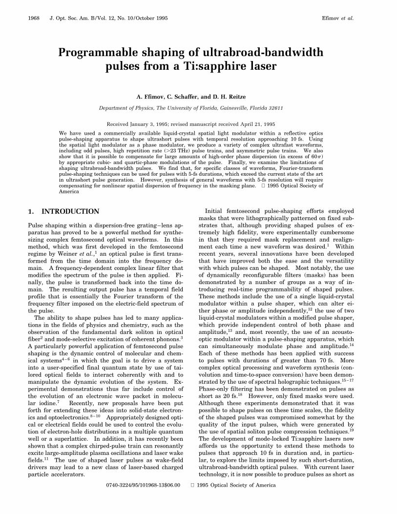
Results for three different trains are shown in Fig. 6.The first [Fig. 6(a)] is a train of three pulses in which theamplitudes and the interpulse spacings are varied. Theagreement between the target train (dashed curve),the numerically synthesized pulse train in which theoptimal mask is used (dotted-dashed curve), and the ex-perimental cross correlation (solid curve) is excellent,with slight deviations in the amplitudes (,10%) and po-sitions (,5 fs) of the experimentally synthesized train.Approximately 92% of the initial pulse energy residesin the target pulses, in good agreement with numeri-cal results. Because the theoretical plots have not beenconvolved with the original reference pulse, the slighttemporal broadening is an artifact of the cross correla-tion. Figure 6(b) depicts a train of three equal ampli-tude pulses in which both interpulse spacings and pulsedurations are varied. Again we find reasonably goodagreement between the target and the cross correlation.Temporal positions agree to within ,10 fs, and, with theexception of the first pulse in the train, pulse durationsare within ,10% of the target. In the worst case, theamplitudes vary by ,25% of the target value. Finally,in Fig. 6(c) we display a chirped-pulse train consistingof six replica pulses. Once again, we observe minimal
Fig. 6. Cross correlations of asymmetric, chirped trains of fem-tosecond pulses generated by 64 gray-level phase masks designedwith simulated annealing. Each panel shows the target (dashedcurve), the numerical results (dotted-dashed curve), and theexperimental cross correlation (solid curve).

Efimov et al. Vol. 12, No. 10 /October 1995 /J. Opt. Soc. Am. B 1973
deviations (,10 fs) from the peak target pulse positions.Excluding the initial pulse, experimental cross-correlationamplitudes are within 15% of their target values. Theinitial pulse has a peak amplitude of approximately 40%of the target value, and slight variations in pulse dura-tions are observed.
4. COMPENSATION OF CUBIC- ANDQUARTIC-PHASE DISPERSIONSCompensation of high-order phase dispersion in pulse-compression and pulse-amplification applications is an-other potential application of programmable pulse shap-ing. The propagation of ultrabroad-bandwidth pulsesthrough dispersive media results in severe pulse broad-ening as frequency-dependent phase shifts accumulate.For optical pulses with spectra that are not too broad(i.e., that satisfy Dvyv0 ,, 1), the phase of an opticalpulse propagating through dispersive media can be con-veniently expressed in a Taylor series as
Fsvd Fsv0d 1 Fs1dsvdsv 2 v0d 112 !
Fs2dsvdsv 2 v0d2
113 !
Fs3dsvdsv 2 v0d3 114 !
Fs4dsvdsv 2 v0d4
1 . . . , (4)
where v0 is the center frequency of the pulse andFsndsvd sdnFydvndvv0 is the nth-order derivative ofthe phase evaluated at v0. The group delay and thelinear dispersion of an optical pulse are given by the lin-ear term Fs1d and the quadratic term Fs2d, respectively.Compensation of linear dispersion is normally accom-plished through the use of grating or prism pairs33,34;however, for pulse compression of sub-10-fs pulses35 orchirped-pulse amplification of sub-100-fs pulses,26,36 can-cellation of higher-order phase dispersion fFs3d, Fs4dg isessential for optimizing the fidelity and the durationof the pulse. Methods for compensating for higher-orderdispersion include the use of ray-tracing algorithms to de-sign amplifiers in which phase dispersion cancels at eachorder26 and the incorporation of adjustable air-spaceddoublet lenses into stretchers that provide independentcontrol of third- and fourth-order dispersions.25 In thissection, we show that large cubic-fFs3dg and quartic-fFs4dgphase shifts (over 120p) can be imprinted on pulses bythe programmable pulse shaper.
We impart the cubic phase on a pulse by com-puting the frequency-dependent phase, DFcubicsvd s1y3!dFs3dsv0dsv 2 v0d3, and then mapping this onto themasking plane. Because the liquid-crystal SLM is re-stricted to phase shifts of 2p, larger phase shifts areaccomplished when the phase is folded back into therange 2p # DF # p; DFfoldsxd DFcubicsxd 2 s2N 1 1dp.Moreover, because the SLM is pixelated, it cannot im-print a smooth continuous-phase profile. Instead, thespectrum is sampled by the modulator at discrete points,DFnsxd DFsxnd, where xn is the position of the nthpixel. As discussed by Weiner et al., these sampling cri-teria place an upper limit of DF p between pixels,thus limiting the total amount of phase shift that can beimparted to a pulse.12 In our experiments, this placesan upper limitation of approximately 130p of total phase
shift. Clearly any increase in pixel number of the SLMwill allow for larger phase shifts.
In Fig. 7(a), we show the cross correlation of a pulsewith a cubic chirp of Fs3d 6.0 3 104 fs3, which corre-sponds to a total phase shift of ,12p over a 100-nm band-width. For comparison, a theoretical intensity profile isalso shown. The experimental cross correlation (solidcurve) shows remarkable fidelity and agrees well withthe theoretical intensity profile for a cubic-phase modula-tion placed on a Gaussian-pulse spectrum (dashed curve).The temporally chirped, oscillatory prepulse is character-istic of cubic chirp in which equally temporally advancedhigher- and lower-frequency components lead the pulseand interfere with each other. The effects of samplingare clearly evident in Fig. 7(b), which shows a cross cor-relation for a cubic chirp of Fs3d 6.0 3 105 fs3 (a phaseshift of 121p). The lobe shows three distinct peaks, anda pulse substructure is seen on the trailing edge of thepulse. Undersampling is also evident in the theoreticalintensity profile, in which a Gaussian spectrum was sam-pled at 128 points. In Fig. 8, we display linear [Fig. 8(a)]and semilog [Fig. 8(b)] plots of the cross correlation of apulse that has a cubic chirp Fs3d 2.75 3 105 fs3 (a phaseshift of 60p). Oscillations are clearly visible over the en-tire pulse (,1.2 ps).
Similar results are seen for quartic-phase profiles,which are shown in Fig. 9. Figure 9(a) displays an ex-perimental cross correlation (solid curve) and a theoreti-cal intensity profile (both plotted on a linear scale) forFs4d 1.1 3 105 fs4 (a phase shift of 40p). Good agree-ment in the main pulse and the first sidelobe is seen, withdeviations occurring in the wings. In particular, the ex-perimental trace shows some asymmetry. Slight oscilla-
Fig. 7. Experimental cross correlations (solid curves) and nu-merical simulations (dashed curves) of a pulse with a cubic-phasemodulation of (a) Fs3d 6 3 104 fs3 s12pd, (b) Fs3d 6.0 3 105 fs3
s122pd. The effects of aliasing are clearly seen in (b).

1974 J. Opt. Soc. Am. B/Vol. 12, No. 10 /October 1995 Efimov et al.
Fig. 8. (a) Cross correlation of a pulse with a cubic-phase mod-ulation of Fs3d 3.0 3 105 fs3, (b) semilog plot of the same pulse.Oscillations are clearly visible over the entire pulse (,1.4 ps).
tions of the shaped pulse appear at negative time delays.These deviations are more pronounced in Fig. 9(b), whichcorresponds to a quartic phase of Fs4d 1.1 3 106 fs4
(a phase shift of 400p). These asymmetries are causedby residual cubic-phase dispersion present on the pulseand have two causes. First, imperfect alignment of thespectrum with the filter will necessarily result in theintroduction of lower-order terms in the phase disper-sion, i.e., DFsvd s1y4!dFs4dsv0dfv 2 sv0 2 Dvdg4 øAsv 2 v0d4 1 Bsv 2 v0d3, where A and B are coeffi-cients that depend on Dv. Second, any nonlinearity inthe spatial frequency dispersion will also introduce lowerterms into the phase expansion.
5. LIMITATIONS OF DISCRETEFOURIER-TRANSFORM PULSE SHAPINGIn the previous sections, we have shown that a vari-ety of temporal waveforms can be produced by usingultrabroad-bandwidth pulses coupled with programmablepulse-shaping techniques. In this section we ask, Whatare the limitations that ultrabroad bandwidths imposeon pulse shaping? Large bandwidths can adversely af-fect the quality of shaped pulses because of (i) higher-order phase dispersion of the pulse during propagationthrough the shaper, which can lead to pulse broadeningand loss of temporal resolution; (ii) higher-order spatialdispersion of the frequency components in the Fourierplane of the shaper, which can lead to deviations fromthe ideal pulse shape; and (iii) amplitude and phase fil-tering of the pulse from other optical elements (gratings,mirrors) in the shaper, which can also lead to pulse broad-ening. In this section we discuss these considerationsin shaping ultrabroad-bandwidth pulses and, in particu-
lar, examine the limits of Fourier-transform techniquesin shaping pulses on pulses with durations that are muchshorter than those used in these experiments.
A. Effects of High-Order Spectral DispersionFirst we consider the effects of higher-order phase disper-sion on the fidelity of the shaped pulse. An ultrabroad-bandwidth pulse that propagates through the pulseshaper will be broadened because of the presence of anintrinsic higher-order phase that manifests itself as aloss of temporal resolution of the individual features ofthe shaped pulse. The magnitude of this broadening de-pends on both the amount of dispersive material presentin the shaper and on dispersive contributions from thediffraction gratings. In principle, any residual phasedispersion can be automatically compensated for by theadjustment of the phases of individual modulator pix-els (as we have done in our cubic- and quartic-phasecompensation experiments above). This permits addedflexibility both for correcting intrashaper dispersion andcorrecting for an uncompensated higher-order phase thatmay be present on input pulses. Nonetheless, it is use-ful to consider to what extent intrinsic phase dispersionbroadens short pulses and to determine the pulse dura-tions for which this intrinsic broadening can be ignored.
Any material (SLM) contributions to positive second-order group velocity dispersion (GVD) within the shapercan be canceled if the position of the final grating is ad-justed. In this case, negative GVD is introduced whenthe grating is moved beyond the outer focal plane ofthe final mirror (see Fig. 1). However, this also intro-duces phase dispersion at higher orders, particularly
Fig. 9. Experimental cross correlations (solid curve) andnumerical simulations (dashed curve) of a pulse with aquartic-phase modulation of (a) Fs4d 1.1 3 105 fs4 s40pd, (b)Fs4d 1.1 3 106 fs4 s400pd. The slightly asymmetric profilesare caused by residual cubic-phase dispersion.

Efimov et al. Vol. 12, No. 10 /October 1995 /J. Opt. Soc. Am. B 1975
cubic- and quartic-phase dispersions. Both the mate-rial and the grating contributions can be calculated. Wecan estimate the material contributions of quadratic-,cubic-, and quartic-phase distortions by using the fiberpropagation parameter,37 bsvd FsvdyL, where L is thepropagation distance, and, by using the Taylor seriesexpansion for the optical phase [Eq. (4)], we can writebsndsvd FsndsvdyL sdnbydvndvv0 . The derivativesbsndsvd are given in terms of the index of refraction as
bs2dsvd l3
2pc2
d2ndl2
, (5a)
bs3dsvd 2l4
4p2c3
√3
d2ndl2 1 l
d3ndl3
!, (5b)
bs4dsvd l5
p3c4
√34
d2ndl2
1 ld3ndl3
1l2
4d4ndl4
!. (5c)
Using a propagation length of 4.6 mm and the Sellmeierequations for fused silica, we estimate that the SLM con-tributes approximately 170 fs2, 2360 fs3, and 500 fs4 ofquadratic, cubic, and quartic phases, respectively. Thesephases must be added to contributions from the gratingsin the shaper. Stern et al. have considered the propa-gation of subpicosecond pulses through a generalizedpulse-shaping system that consists of two gratings anda unit magnification pair of focusing elements (lens).38
From their analysis, the excess cubic- and quartic-phaseterms are found to be 1430 fs3 and 2640 fs4, respec-tively. When the final grating position is set to cancelthe GVD that is due to the gratings, jFgrating
s2dsvdj 2jFmaterial
s2dsvdj, the residual cubic and quartic phasescan be computed as the sum of contributions from mate-rial and gratings. We experimentally measure a gratingdisplacement of 600 mm from the focal plane, in rea-sonable agreement with the calculated value of 400 mm.Using the experimentally measured value for the grat-ing phase, we estimate total cubic and quartic phases of360 fs3 and 2100 fs4, respectively, of our shaper. Forreference, a cubic (quartic) phase of 360 fs3 (2100 fs4)will broaden an 12.2-fs (4.5-fs) pulse by 1 fs. When thecondition that intrinsic phase dispersion can effectivelybe neglected when Dtyt # 1.1 is imposed, higher-orderphase dispersion can be neglected for pulse durations thatexceed 12 fs. For pulses shorter than this, phasecompensation by a SLM is necessary to eliminate pulsebroadening. Note, however, that the phase dispersioncontributions from material and gratings have oppositesigns. It should therefore be possible to select the appro-priate grating angle to cancel quadratic and cubic phasessimultaneously.38 In addition, our analysis does not takethe effect of finite beam diameter into account, which canlead to pulse broadening across the beam radius. Sucheffects can in principle be minimized by the use of a one-dimensional spatial image inverter in a quadruple-passconfiguration,26 although complications that are due tothe presence of SLM may exist.
B. Effects of Higher-Order Spatial DispersionWe next consider the variation of spatial dispersion inthe masking plane of the shaper and its consequence onthe shaped output pulses. The pulse shaper operates by
imposing a complex linear filter Msvd on an input fieldspectrum Einsvd. However, the filtering operation is car-ried out in real space; hence Msvd must be mapped fromspace to frequency. For small bandwidths sDvyv0 ,, 1d,dvydx is constant, and the filter is simply a one-to-onelinear map from space to frequency. For our experimen-tal conditions, Dvyv0 0.16, and the assumption of con-stant dispersion is invalid, as dvydx varies by 40% overthe baseband spectrum of our pulses (even though dlydxvaries by only 6%). Because we are using fixed pixel sizeand spacing dictated by the physical characteristics of theSLM, any nonlinearity in spatial dispersion represents adeviation from the desired frequency filter.
To model the effects of spatial nonlinearity, we expandthe wavelength at the masking plane to third order in aTaylor series:
lsxd l0 1 ls1dsxdDx 112 !
ls2dsxdsDxd2 113 !
ls3dsxdsDxd3 ,
(6)
where lsndsxd sdnlydxndll0 , l0 is the center wavelengthof the pulse, and Dx is the distance from the mask cen-ter sx0 0d. We evaluate the wavelength derivativesby considering the geometry of the shaper. Referring toFig. 10, let f be the grating distance from the focusing op-tic and V ud 2 ud,0 be the difference angle between l
and l0. The position of l at the masking plane is givenby
x f tan V . (7)
The relationship between V and l is obtained from thefirst-order grating equation:
dfsin ui 1 sinsV 1 ud,0dg l . (8)
From Eqs. (7) and (8) and their respective derivatives,complicated expressions for the wavelength derivativesdnlydxn can be found at arbitrary V. However, whenevaluated at V 0 sl l0d, the expressions simplifyconsiderably:
Fig. 10. Geometry for calculating the effects of higher-orderspatial dispersion in the masking plane.

1976 J. Opt. Soc. Am. B/Vol. 12, No. 10 /October 1995 Efimov et al.
√dl
dx
!l0
d cos ud,0
f, (9a)√
d2l
dx2
!l0
2d sin ud,0
f 2, (9b)√
d3l
dx3
!l0
23d cos ud,0
f 3. (9c)
For our experimental parameters, we find that dlydx 11.76 nmymm, d2lydx2 25.02 3 1022 nmymm2, andd3lydx3 22.26 3 1023 nmymm3, respectively. InFig. 11 we plot the position-dependent wavelength byusing Eq. (7) (solid line). For comparative purposes,both the linear spatial dispersion (dashed line) and theexact position calculated with Eqs. (8) and (9) are shown.Several features are apparent. First, the deviation fromlinearity is negligible (,5%) over a bandwidth of 120 nm,approximately the baseband spectrum of our pulses.Second, there is no difference between our derived third-order result and the exact position over 400 nm ofbandwidth. This is shown clearly in the inset, whichis a blowup of the bottom left-hand corner. Thus we canmake an accurate assessment of the effects of nonlinearspatial dispersion on optical pulses with bandwidths thatnear the single-cycle limit sDvyv0 , 0.3d by using thethird-order expansion.
It is crucial to note that, although the wavelength dis-persion is nearly linear, the frequency dispersion is in factquite nonlinear. This is shown clearly in Fig. 12. Wenote that a shaper that possesses a purely linear spa-tial wavelength dispersion over hundreds of nanometersof bandwidth will necessarily possess a significant amountof nonlinear frequency spatial dispersion. For a devicethat has a fixed pixel size (such as a liquid-crystal SLM),this results in a variation in the amount of frequency thatis transmitted through each pixel. Rigorously, the spec-tral filter including nonlinear dispersion is given by39
Msvd
√2
pw02
!1/2 ZdxMsxdexp
(22sx 2 f fvgd
w02
),
(10)where M(x) is the physical mask, w0 is the electric-fieldradius at the masking plane, and the nonlinear spatialdispersion is
f svd dxdv
v 112!
d2xdv2
v2 113!
d3xdv3
v3 1 · · · . (11)
For a discrete N pixel filter, the physical mask can bewritten as12
Msxd
24CsxdN /221X
n2N /2
dsx 2 ndxd
35 p rect
√x
dx
!, (12)
where C(x) is the continuous spatial mask that corre-sponds to the desired frequency filter, assuming linearspatial dispersion, dx is the physical width of the pixel,the function rectsxd 1 for jxj # 1y2 and 0 otherwise, and* is the convolution operator. With Eqs. (10) and (12),under the assumption that the field radius (spot size) atthe masking plane is much smaller than the pixel width(as in our case), the spectral filter becomes
Msvd
8<:Cf f svdgN /221X
n2N /2
df f svd 2 ndxg
9=; p rect
"f svddx
#.
(13)
From Eq. (13), two features are noteworthy. First, thedelta-function terms explicitly show that the frequencyis not sampled at equal intervals. Second, as f svdydxvaries with frequency, the amount of transmitted fre-quency per pixel is not constant.
To examine these effects on the fidelity of shapedultrabroad-bandwidth pulses, we have performed simula-tions on pulses with 5-fs duration in which the nonlinearspatial dispersion is incorporated in the filtering process.We first compute the continuous spatial filter C(x) thatcorresponds to our desired frequency filter under the as-sumption of a purely linear frequency-space map. Theactual frequency-dependent filter Msvd that samples thepulse spectrum [Eq. (13)] is constructed by the mappingof space to frequency (including nonlinear spatial disper-sion) directly from the wavelength expansion [Eq. (6)] andvsxd 2pcylsxd. We include the effect of pixelation bydiscretizing and sampling the input field spectrum at the128 appropriate points in frequency space according toEq. (13). This corresponds to a frequency range (at thecenter frequency v0d of 2.5 THzypixel and a corresponding
Fig. 11. Spatial wavelength dispersion in the masking planeof the shaper, showing linear dispersion (dashed curve) andthird-order dispersion (solid curve). The exact position of thewavelength in the masking plane is identical to the third-orderresult over this wavelength.
Fig. 12. Spatial frequency dispersion in the masking plane ofthe shaper, plotted in angular terahertz, obtained from thethird-order wavelength result. FWHM bandwidths for 21, 10,and 5 fs are shown for reference.
Efimov et al. Vol. 12, No. 10 /October 1995 /J. Opt. Soc. Am. B 1977
(linear) temporal window of 400 fs. The shaped intensityprofile of the pulse is computed by30
I std 1
s2pd2
Zdv0 expsiv0td
ZdvEout svdp
3 Eoutsv 1 v0d , (14)
where the shaped field is given by Eoutsvd EinsvdMfvsxdg. For these simulations, we use aGaussian intensity spectrum of the form Iinsvd E0
2 exps24 ln 2 v2yDvFWHM2d where Dv 88 THz and
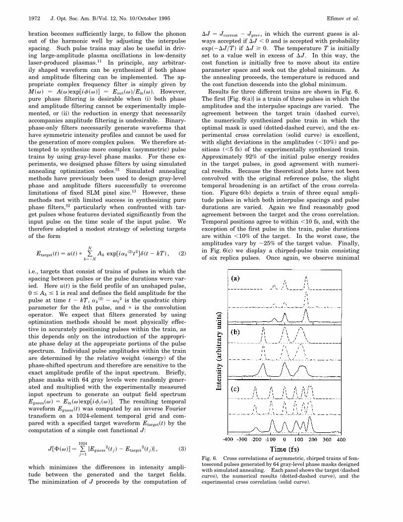
corresponds to a 5-fs pulse. To model the finite spatialextent of our hypothetical SLM, the intensity spectrum istruncated at four e-foldings. In this manner, ringing andfeature broadening associated with hard spectral aper-tures are minimized. hHowever, because the wavelengthdispersion [Eq. (6)] was computed with the parameters ofour current shaper, the physical size of our hypotheticalSLM must be ,40 mm to accommodate this bandwidth.jThree representative filters are considered in our simu-lations: a double-slit amplitude filter, an M-sequencephase filter, and sinsvdyv phase and amplitude filter.
Results for the double-slit filter are shown in Fig. 13.Selecting two separate, phase-locked portions of the spec-trum results in a temporal beat note with a period thatcorresponds to the inverse mean frequency separation ofthe spectra. For ordinary (linear) filtering, the width ofthe temporal envelope would correspond to the inverseof the transmitted frequency range of the slit. In eachof these simulations, the spatial filter was constructedto have slits of equal physical width centered aboutthe physical position of the central wavelength. Whentransformed into frequency space, the spatial nonlinearityasymmetrically positions the slits with respect to the spec-trum. In addition, the amount of transmitted frequencyrange is different in each slit. Figure 13(a) displays thecomputed output temporal profile for a mean frequencyseparation of 66.8 THz, which corresponds to a pulseperiod of 15 fs. In this simulation, the left (right) slitwas positioned at 26 mm (6 mm) with widths of 2 mm.The transmitted frequency range through the left (right)slit was 13.6 THz (9.4 THz). The width of the temporalenvelope is 78 fs, which is nearly the value expected forthe wider slit width of 13.6 THz. A series of isolatedpulses are seen, and pulse positions correspond to theirexpected values. Figure 13(b) displays the output pulseprofile for a mean frequency separation of 138.1 THz anda pulse spacing of 7.2 fs. Here, the left (right) slit waspositioned at 212 mm (12 mm) with widths of 6 mm, andthe transmitted frequency range through the left (right)slit was 52.3 THz (22.6 THz). Again we find that thepulses are isolated in their appropriate positions with atemporal envelope width of 27.5 fs.
In Fig. 14, results for a length 7 M-sequence with a5.0-fs input pulse are shown for a dF 62.5 THz train.The M-sequence was discussed in Section 3 above andhas been previously used for shaping pulse trains.30 Forthese simulations, Df 1.1p and six repetitions of theM-sequence spanned the spectrum. The quality of thesynthesized pulse train has degraded with respect to atrain simulated assuming purely linear frequency dis-persion (shown as the offset dashed curve). The centralpulse in the train maintains its width, but the temporally
shifted pulses are broadened by as much as a factor of2 and deteriorate beyond the third pulse in the trains.Evidence for this is present in our experimental cross cor-relations of a 23.5-THz train shown in Fig. 6(c).
Finally, in Fig. 15 we display simulations for tem-poral square pulses of 50-, 100-, and 300-fs durations.Here the filter chosen was sinspxyx0dyspxyx0d with x0 fT sdnydxdnn0 g21, where T is the duration of the squarepulse and sdnydxdnn0 is the frequency dispersion at thecenter frequency of the pulse. Again, ideal square pulsesare shown as the offset dashed curve. For the 50-fssquare pulse [Fig. 15(a)], slight deviations appear alongthe leading and the trailing edges of the pulses, includinga 15% overshoot of the main plateau and a slight broaden-ing of the rise and fall time from 5 to 8 fs. Both of theseeffects grow as the square pulse duration is increased,with a 100- (300-) fs square pulse [Figs. 15(b) and 15(c)]suffering a 13- (25-) fs broadening and a 25% (34%) over-shoot of the main plateau. In the case of the 300-fs pulse,ringing appears on both the leading and the trailing edgeof the pulses. In all cases, however, the overall characterof the square pulse is preserved.
Our simulations suggest that although nonlinear spa-tial effects play a minimal role in simple filters (such asdouble slits) on 5-fs time scales, they can affect the fi-delity of complicated waveforms (such as square pulses)and in the worst case render a seriously degraded wave-form (as evidenced in our simulations of M-sequence fil-ters). Specifically, as the square pulse illustrates, thequality of the pulse degrades with increasing waveformduration. One possible cause of these effects can be un-
Fig. 13. Numerical simulations of (a) 66.8-THz, (b) 138.1-THzpulse trains that incorporate the effects of higher-order spa-tial dispersion, assuming a transform-limited 5-fs input pulse.These trains were synthesized by the use of an amplitude maskthat consisted of two slits of equal spatial dimension centeredabout x 0 in the masking plane.

1978 J. Opt. Soc. Am. B/Vol. 12, No. 10 /October 1995 Efimov et al.
Fig. 14. Numerical simulation of a 62.5-THz pulse train (solidcurve) that shows the effects of higher-order spatial dispersion,synthesized with a length 7 M-sequence phase mask. The fi-delity of this train is significantly degraded with respect to atrain synthesized assuming only linear frequency dispersion inthe masking plane (dashed curve).
derstood by considering the variance of the transmittedfrequency as a function of pixel position. For a filterwith purely linear spatial dispersion (assuming w0 ,, dxd,the temporal window available for shaping is given by1ydv, where dv is the transmitted frequency per pixel.For large bandwidths, however, 1ydv varies considerablyover the pulse bandwidth. In our simulations, 1.4 THz ,
dv , 3.7 THz at two e-foldings, which effectively reducesthe shaping window to ,270 fs. Moreover, the simulatedM-sequence pulse train displays degradation well withinthe 270-fs window, indicating that nonlinear samplingplays an important role. Because the M-sequence trainis constructed by the phase shifting of specific frequenciesto interfere constructively at the appropriate pulse posi-tions, incorrect sampling of the frequency will compromisethe interference and necessarily degrade the waveform.Therefore, for the most general waveform, the effects ofnonlinear spatial dispersion will need to be compensatedfor. If the optical bandwidths of the pulses are known apriori, this could be accomplished in systems that utilizefixed masks simply if the filter is designed to incorpo-rate the frequency dispersion directly. This has the dis-advantage of the need to fabricate, replace, and realign anew mask for each new set of waveforms. Similarly, onecould design a pixelated SLM device that exactly incorpo-rates the frequency-to-space nonlinear mapping by havingunevenly spaced pixels with varied physical dimensionssuch that the amount of frequency transmitted per pixelis constant over the entire bandwidth of the pulse. Thiswould require the fabrication of a specialized device. Athird possibility is to increase the frequency resolution by
increasing the number of pixels. This, however, presentsdisadvantages in any implementation. In an SLM, thedecreased pixel size would result in a filter that convolvesthe desired filter with the intensity profile of the inputbeam.39 An acousto-optic modulator14 would overcomethis problem by virtue of its quasi-continuous pixelation.However, the wavelength variation of the Bragg diffrac-tion angle and diffraction efficiency that necessarily ac-company ultrabroad-bandwidth pulses would need to beaddressed before this method could be applied. A fourthpossibility is simply to assign the correct phase to the ap-propriate (nonlinear) spatial position. This guaranteesthat the spectrum is sampled correctly.
C. Effects Of Extraneous Amplitude FiltersFinally, we briefly consider amplitude filtering ef-fects that can compromise the fidelity of shaped wide-bandwidth pulses. Some amplitude shaping can be ex-pected by the diffraction gratings within the shaper, asdiffraction efficiency varies both with wavelength and po-larization. We have not characterized the spectral trans-mission of our shaper; however, we note that for 13-fs
Fig. 15. Numerical simulations of (a) 50-fs, (b) 100-fs, (c) 300-fssquare pulses (solid curve) synthesized with sinspxyx0dyspxyx0dphase and amplitude filters. For comparison, ideal squarepulses (dashed curve) synthesized assuming linear frequencydispersion are also displayed.

Efimov et al. Vol. 12, No. 10 /October 1995 /J. Opt. Soc. Am. B 1979
pulses, these effects are minimal based on our measuredunshaped cross correlations. For shorter pulses with cor-respondingly broader bandwidths, these effects may be-come important, particularly if the shaper is operated ina multipass configuration. Typically, grating efficienciescan be as broad as several hundred nanometers for highgroove-density gratings. However, grating bandwidthsdiminish as groove density decreases and may presentproblems for pulses with durations that approach single-cycle limits.
6. CONCLUSIONWe have demonstrated that spectral domain femtosec-ond pulse-shaping techniques can be easily applied toultrabroad-bandwidth pulses with durations as short as13 fs. A variety of temporal profiles has been generatedby the use of a programmable spatial light phase modu-lator within a dispersion-free pulse-shaping apparatus.Although we have performed phase filtering in these ex-periments, amplitude and combined phase and amplitudefiltering should be possible with similar temporal reso-lution. We have also demonstrated the feasibility of us-ing a SLM-based shaper as a high-order phase disper-sion compensator for ultrabroad-bandwidth femtosecondpulses. From the numerical modeling of the effects ofphase dispersion and spatial dispersion within the shaper,we conclude that these methods can be extended to pulseswith durations that approach a single optical cycle, pro-vided that filters that adequately account for the nonlin-ear spatial dispersion in the masking plane are designed.
ACKNOWLEDGMENTSThis research was supported by the National ScienceFoundation (ECS9409297). The authors thank HenryKapteyn and Christopher Barty for their helpful sugges-tions concerning operation of the mode-locked Ti:sapphirelaser.
REFERENCES1. A. M. Weiner, J. P. Heritage, and E. M. Kirschner, “High-
resolution femtosecond pulse shaping,” J. Opt. Soc. Am. B5, 1563 (1988).
2. A. M. Weiner, J. P. Heritage, R. J. Hawkins, R. N. Thurston,E. M. Kirschner, D. E. Leaird, and W. J. Tomlinson, “Ex-perimental observation of the fundamental dark soliton inoptical fibers,” Phys. Rev. Lett. 61, 2445 (1988).
3. A. M. Weiner, D. E. Leaird, G. P. Wiederrecht, and K. A. Nel-son, “Femtosecond pulse sequences used for optical controlof molecular motion,” Science 247, 1317 (1990); “Femtosec-ond multiple-pulse impulsive stimulated Raman scatteringspectroscopy,” J. Opt. Soc. Am. B 8, 1264 (1991).
4. H. Rabitz and S. Shi, “Optimal control of molecular motion:making molecules dance,” in Vibrational Spectroscopy,J. Bowman, ed. (Jai, Greenwich, Conn., 1991), Vol. 1, Part A,p. 187.
5. W. S. Warren, H. Rabitz, and Mohammed Dahleh, “Coherentcontrol of quantum mechanics: the dream is alive,” Science259, 1581 (1993).
6. Y. Yan, R. E. Gillilan, R. M. Whitnell, K. R. Wilson,and S. Mukamel, “Optical control of molecular dynamics:Liouville-space theory,” J. Chem. Phys. 97, 2320 (1993).
7. B. Kohler, J. L. Krause, R. M. Whitnell, K. R. Wilson, V. V.Yakovlev, and Y. Yan, “Quantum control of vibrational dy-namics with tailored light pulses,” in Ultrafast Phenomena
IX, G. A. Mourou, A. H. Zewail, P. F. Barbara, and W. H.Knox, eds. (Springer-Verlag, Berlin, 1994), p. 44.
8. P. C. M. Planken, I. Brener, M. C. Nuss, M. S. C. Lou,and S. L. Chuang, “Coherent control of terahertz chargeoscillations in a coupled quantum well using phase-lockedoptical pulses,” Phys. Rev. B 48, 4903 (1993).
9. A. M. Weiner, “Enhancement of coherent charge oscillationsin coupled quantum wells by femtosecond pulse shaping,”J. Opt. Soc. Am. B 11, 2480 (1994).
10. P. Hyldgaard, G. D. Sanders, and D. H. Reitze, “Coherentoptical control of electron dynamics in asymmetric doublequantum wells in the nonimpulsive regime,” presented atthe Annual Meeting of the Optical Society of America, Dal-las, Tx., October 1994.
11. D. Umstadter, E. Esarey, and J. Kim, “Nonlinear plasmawaves resonantly driven by optimized laser pulse trains,”Phys. Rev. Lett. 72, 1224 (1994).
12. A. M. Weiner, D. E. Leaird, J. S. Patel, and J. R. Wullert,“Programmable femtosecond pulse shaping by use of a mul-tielement liquid-crystal phase modulator,” Opt. Lett. 15,326 (1990); “Programmable shaping of femtosecond opticalpulses by use of 128-element liquid crystal phase modula-tor,” J. Quantum Electron. 28, 908 (1992).
13. M. A. Wefers and K. A. Nelson, “Programmable phase andamplitude femtosecond pulse shaping,” Opt. Lett. 18, 2032(1993).
14. C. W. Hillegas, J. X. Tull, D. Goswami, D. Strickland, andW. Warren, “Femtosecond laser pulse shaping by use of mi-crosecond radio-frequency pulses,” Opt. Lett. 19, 737 (1994).
15. A. M. Weiner, D. E. Leaird, D. H. Reitze, and E. G. Paek,“Spectral holography of shaped femtosecond pulses,” Opt.Lett. 17, 224 (1992); “Femtosecond spectral holography,”IEEE J. Quantum Electron. 28, 2251 (1992).
16. A. M. Weiner and D. E. Leaird, “Femtosecond signal pro-cessing by second-order spectral holography,” Opt. Lett. 19,123 (1994).
17. M. C. Nuss, M. Li, T. H. Chiu, A. M. Weiner, and A. Partovi,“Time-to-space mapping of femtosecond pulses,” Opt. Lett.19, 664 (1994).
18. D. H. Reitze, A. M. Weiner, and D. E. Leaird, “Shaping ofwide bandwidth, 20 fsec optical pulses,” Appl. Phys. Lett.61, 1260 (1992).
19. D. H. Reitze, A. M. Weiner, and D. E. Leaird, “Spatial solitonpulse compression,” Opt. Lett. 16, 1409 (1991).
20. J. Zhou, G. Taft, C. Shi, H. C. Kapteyn, and M. C. Murnane,“Sub-10 fs pulse generation in Ti:sapphire: capabilities andultimate limits,” in Ultrafast Phenomena IX, G. A. Mourou,A. H. Zewail, P. F. Barbara, and W. H. Knox, eds. (Springer-Verlag, Berlin, 1994), p. 39.
21. I. P. Christov, M. M. Murnane, H. C. Kapteyn, J. P. Zhou,and C. P. Huang, “Fourth-order dispersion-limited solitarypulses,” Opt. Lett. 19, 1465 (1994).
22. J. D. Kmetec, J. J. Macklin, and J. F. Young, “0.5-TW, 125-fsTi:sapphire laser,” Opt. Lett. 16, 1001 (1991).
23. A. Sullivan, H. Hamster, H. C. Kapteyn, S. Gordon,W. White, H. Nathel, R. J. Blair, and R. W. Falcone, “Mul-titerawatt, 100-fs laser,” Opt. Lett. 16, 1406 (1991).
24. C. P. Barty, C. L. Gordon, and B. E. Lemoff, “Multiterawatt30-fs ti-sapphire laser system,” Opt. Lett. 18, 1442 (1994).
25. W. E. White, F. G. Patterson, R. L. Combs, D. F. Price, andR. L. Shepherd, “Compensation of higher-order frequency-dependent phase terms in chirped-pulse amplification sys-tems,” Opt. Lett. 18, 1343 (1993).
26. B. E. Lemoff and C. P. J. Barty, “Quintic-phase-limited,spatially uniform expansion and recompression of ultrashortoptical pulses,” Opt. Lett. 18, 1651 (1993).
27. M. T. Asaki, C. P. Huang, D. Garvey, J. P. Zhou, H. C.Kapteyn, and M. M. Murnane, “Generation of 11-fs pulsesfrom a self-mode-locked Ti-sapphire laser,” Opt. Lett. 18,977(1993).
28. See, for example, E. Hecht and A. Zajac, Optics (Addison-Wesley, Reading, Mass., 1976), p. 323.
29. J. E. Rothenberg, D. Grischkowsky, and A. C. Balant, “Ob-servation of the formation of the 0p pulse,” Phys. Rev. Lett.53, 552 (1984).
30. A. M. Weiner and D. E. Leaird, “Generation of terahertz-

1980 J. Opt. Soc. Am. B/Vol. 12, No. 10 /October 1995 Efimov et al.
rate trains of femtosecond pulses by phase-only filtering,”Opt. Lett. 15, 51 (1990).
31. See, for example, W. H. Press, S. A. Teukolsky, W. T.Vettering, and B. P. Flannery, Numerical Recipes (Cam-bridge U. Press, Cambridge, 1992), Chap. 10.
32. A. M. Weiner, S. Oudin, D. E. Leaird, and D. H. Reitze,“Shaping of femtosecond pulses using phase-only filters de-signed by simulated annealing,” J. Opt. Soc. Am. B 10, 1112(1993).
33. E. B. Treacy, “Optical pulse compression with diffractiongratings,” IEEE J. Quantum Electron. 5, 454 (1969).
34. R. L. Fork, O. E. Martinez, and J. P. Gordon, “Negativedispersion using pairs of prisms,” Opt. Lett. 9, 150 (1984).
35. R. L. Fork, C. H. Brito-Cruz, P. C. Becker, and C. V. Shank,
“Compression of optical pulses to six femtoseconds usingcubic phase compensation,” Opt. Lett. 12, 483 (1987).
36. J. P. Zhou, C. P. Huang, C. Y. Shi, M. M. Murnane, andH. C. Kapteyn, “Generation of 21-fs millijoule-energy pulsesby use of Ti-sapphire,” Opt. Lett. 19, 126 (1994).
37. See, for example, G. P. Agrawal, “Nonlinear Fiber Optics(Academic, Boston, 1989), Chap. 1.
38. M. Stern, J. P. Heritage, and E. W. Chase, “Grating com-pensation of 3rd-order fiber dispersion,” IEEE J. QuantumElectron. 28, 2742 (1992).
39. R. W. Thurston, J. P. Heritage, A. M. Weiner, and W. J.Tomlinson, “Analysis of picosecond pulse shape synthesis byspectral masking in a grating pulse compressor,” IEEE J.Quantum Electron. 22, 682 (1986).