programmable logic controllers. historical background of the plc the first programmable logic...
TRANSCRIPT

Programmable Logic Controllers


Historical Backgroundof the PLC
•The first Programmable Logic Controller was developed by a group of engineers at GENERAL MOTORS in 1968, when the company were looking for an alternative to replace complex relay control systems.

Definition
A digitally operating electronic system, designed for use in an industrial environment, which uses memory for the internal storage of user-oriented instructions for implementing specific functions such as logic, sequencing, timing, counting and arithmetic to control, through digital or analog inputs and outputs, various types of machines or processes.

Advantages of using PLC’s
– Highly reliable– Highly versatile (universal applicability)– Simple troubleshooting– Simple installation– Quick modification of the program (highly flexible)– Capable of task not possible with relays before as indicated by the
ff: calculation information exchange text and graphic display data processing networking– Low space requirement– Low power consumption– High processing speed– No moving parts, hence no wearing parts
Disadvantages of using PLC’s
– High initial cost ( for a simple process )– Sensitive to dust, high temperature and high humidity– Repair must be made by a qualified personnel– Not very widespread– No uniform programming language

System Components
Sensorics
Input ModuleCentral Control Unit
(processing)
Actorics
Output Module
Program
Input Module : Functions
The input module of a PLC is the module to which sensors are connected to. The sensor signals are to be passed on to the central control unit. The important functions of an input module are as follows:
•Reliable signal detection
•Voltage adjustment of control voltage to logic voltage
•Protection of sensitive electronics from external voltages
•Screening of signals

INPUTS
Limit switchesSensorsPushbuttonsRelaysTransmittersSignal Generators
PROCESSORS
Central Control Unit CCUthe most important component of the PLCit directs the operation of the systemit contains the arithmetic logic unitit processes input signals to produce the necessary output signalit has memory to store programs and data to be processedit allows communication with external peripheralsit is interfaced with sensors and actuators using the input and output modules respectively
CCU : Operation
CCU reads or accepts input data or status of field devices via the input interface.CCU executes the control program stored in it’s memory system.Writes or updates the output devices via the output interface.

Output modules conduct the signals of the central control unit to final control elements, which are actuated according to the task. The functions of the output module, as seen from the application of the PLC, include the following:
Output Module : Functions
•Voltage adjustment of logic voltage to control voltage
•Protection of sensitive electronics from spurious voltages from the controller
•Power amplification sufficient for the actuation of major final control elements
•Short circuit and overload protection of output

OUTPUTS
Final control elements RelaysElectrical loads Solenoid coilsLampsIndicatorsAlarms / buzzers

FEC + Ethernet = FC3412 digital Inputs
(PNP/NPN)24 V DCRun / Stop Switch 2 Relay / 6 Transistor
OutputsCOM and EXT
InterfacesEthernet
Twisted PairRJ45 connector10 MBit/s
256 timers, 256 counters256 registers160,000 flag Multitasking186 Micro Processor
FC34 - Hardware Features
PROGRAMMING SOFTWARE FST4, FST IPC 3.21MULTIPROG

FEC Compact
FEC Standard
IPC Standard

Inputs and Outputs:
The PLC has a specified no. of inputs and outputs which connect it to the sensors and actuators.Addresses are therefore required to give a precise designation to the various inputs and outputs.
I : inputO : outputF : flagT : timerC : counter
These operands are entered in the ALLOCATION LIST
TThe I and O are operand characters and are standardized.AAddress numbers are determined by the wiring or plug allocation selected.
Allocation List
The items of equipment associated with the FEC are addressed via operands in the control programs. An operand consists of an abbreviation identifying the equipment group and an address specifying a level within the group. Output 3 in output word 5, for example, is identified as O5.3
Symbolic operands
The FST software also allows you to use symbolic designations for the equipment: O5.3 may switch a motor on and off.For Example, in which case you can refer to it as ‘MotorOn’ in your programs. In this way you can make the programs more easily comprehensible, and also retain a clear overview even when there are a large number of operands. You are largely free to decide on the names of the symbolic operands yourself.

Absolute operands
In the following the direct entry of an operand (such as O5.3) is referred to as an absolute operand, whereas entry in symbolic form (MotorOn) is referred to as symbolic operand. Example:
I0.0O0.0F0.0T0
The assignment of symbolic operands to absolute operands is defined in the allocation list.It is advisable to create the allocation list before program entry and then only to use the symbolic operand designations in the control programs.


Ladder Diagram
– The ladder diagram describes the program in graphic form. It was developed from the relay ladder but is structured in diagrammatic form. It is made up of two vertical lines of which the left one is connected to the voltage source and the right is earthed. The various current paths(rungs) run horizontally between the two (from left to right).

Executive Part
Conditional Part
– Language Elements
- inputs normally closed normally open - outputs
Ladder Diagram
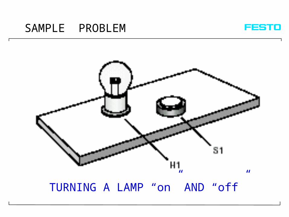
SAMPLE PROBLEM
TURNING A LAMP “on” AND “off”

Ladder Diagram Program of lamp problem
I 0.0 O 0.0
H1S1

Coil Operations
Non-Latching Coil: O0.0 is energized if signal reaches the coil, de-energized if the signal does not.
O0.0
O0.0
O0.0
O0.0
Inverse Non-Latching Coil: O0.0 is energized if signal does not reach the coil, de-energized if the signal does.
.S
R
Set & Hold Coil: O0.0 is energized once signal reaches the coil, remains energized until Reset Coil is activated.(Memorized ON)
Reset Coil: O0.0 is de-energized once signal reaches the coil, remains de-energized until Set & Hold Coil is activated.(Memorized OFF)

Ladder Diagram Contacts
Normally Open Contact:Yes Logic
Closes when a signal is present at I0.0
I0.0
I0.0Normally Close Contact:Not Logic
Opens when a signal is present at I0.0
I0.0 I0.1 O0.1
Output O0.1 is energized when a signal is present at I0.0 and not present at I0.1.

Logic Operations
› AND OPERATION– realized by series connection of two NO contacts
S1 S2 Lamp
Truth Table
S1 S2 Lamp
0 0 0
0 1 0
1 0 0
1 1 1

Logic Operations
Truth Table
S1 S2 Lamp
0 0 0
0 1 1
1 0 1
1 1 1
› OR OPERATION– realized by parallel connection of two NO contacts
S1
S2
Lamp
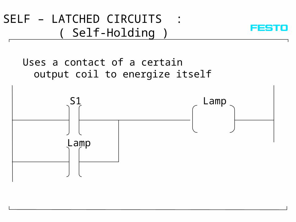
SELF – LATCHED CIRCUITS : ( Self-Holding )
S1
Lamp
Lamp
Uses a contact of a certain output coil to energize itself

Program processing by PLC
1. Instruction2. Instruction
Program
3. Instruction
Last Instruction
4. Instruction


FLAGS
– Flags fulfill the same function as the auxiliary RELAY in the ELECTRICAL CIRCUIT DIAGRAMS.
– It is a relay that is not switched externally but only fulfills a function within the PLC
– They can be used as outputs, except that outputs have an external connection and an external LED, whereas flags are only present and visible within the system.
– All operations that can be used on outputs can be used on flags, for example assignment, setting, resetting, interrogating etc.
– Flags are the ones normally used for latching circuits
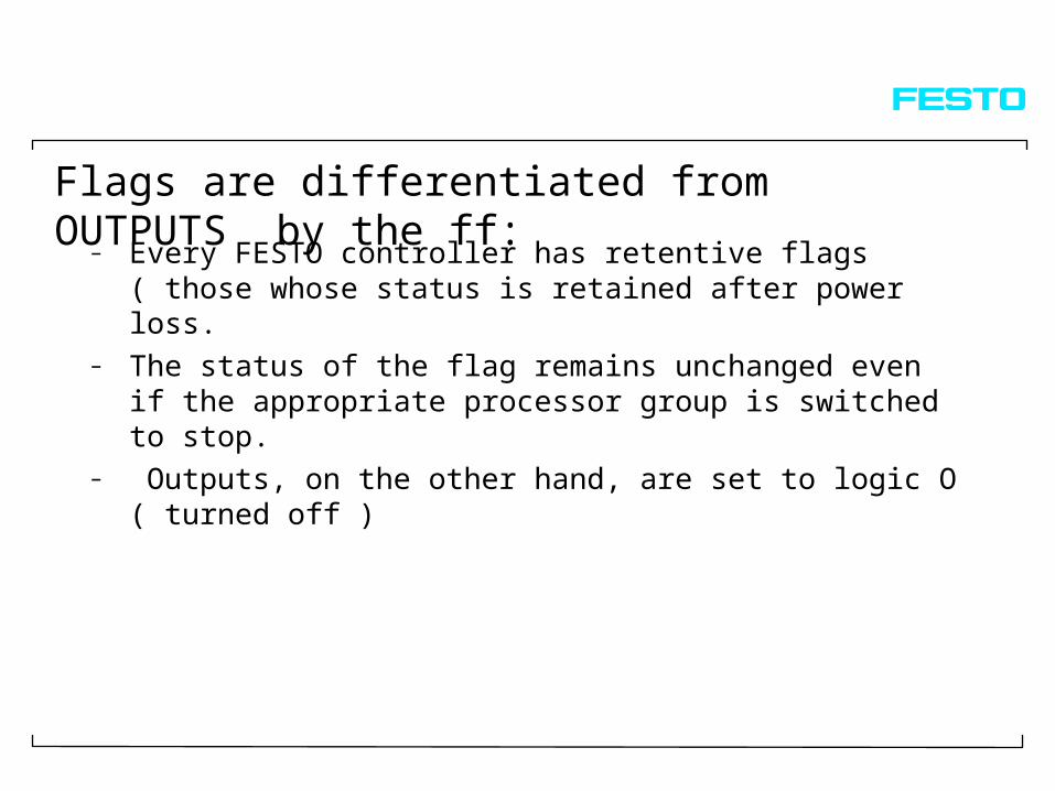
Flags are differentiated from OUTPUTS by the ff:
– Every FESTO controller has retentive flags ( those whose status is retained after power loss.
– The status of the flag remains unchanged even if the appropriate processor group is switched to stop.
– Outputs, on the other hand, are set to logic O ( turned off )

FLAGS
– One bit memories– May be set or reset and interrogated for logic 1 or
0.
a. Conditional Part
b. Executive Part
F1.0 F1.1 O0.0
I0.0 I1.0 F1.0


– The Statement List(STL) is a text based assembly-type language used for programming control tasks in FST.
– An typical STL control program is made up of a number of statements. These statements are the counterpart of “rungs” or “networks” in Ladder Diagram programming.
– Consequently, each of these statements have conditional and executive parts consistent with that of the Ladder Diagram.

IF I 0.0 THEN SET O 0.0OTHRW RESET O 0.0
I 0.0 O 0.0
CONDITIONAL PART
EXECUTIVE PART
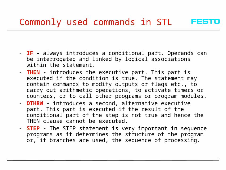
Commonly used commands in STL
– IF - always introduces a conditional part. Operands can be interrogated and linked by logical associations within the statement.
– THEN - introduces the executive part. This part is executed if the condition is true. The statement may contain commands to modify outputs or flags etc., to carry out arithmetic operations, to activate timers or counters, or to call other programs or program modules.
– OTHRW - introduces a second, alternative executive part. This part is executed if the result of the conditional part of the step is not true and hence the THEN clause cannot be executed.
– STEP - The STEP statement is very important in sequence programs as it determines the structure of the program or, if branches are used, the sequence of processing.
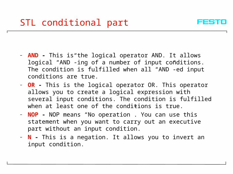
STL conditional part
– AND - This is the logical operator AND. It allows logical “AND”-ing of a number of input conditions. The condition is fulfilled when all “AND”-ed input conditions are true.
– OR - This is the logical operator OR. This operator allows you to create a logical expression with several input conditions. The condition is fulfilled when at least one of the conditions is true.
– NOP - NOP means “No operation”. You can use this statement when you want to carry out an executive part without an input condition.
– N - This is a negation. It allows you to invert an input condition.

STL executive part
– SET - activates a one-bit operand. You can use this for setting outputs, flags, timers, counters and programs to logical one.
– RESET - is the opposite of SET. It deactivates one-bit operands, used, for example, for setting an output to logical zero.
– LOAD - A LOAD statement reads a register or a multibit operand, i.e. its value is written to a multibit accumulator. Normally this statement is followed by the keyword TO, indicating the destination of the operation.
– TO - A TO statement assigns a value to a word operand. TO specifies the destination of the operation.
– JMP TO - A JMP TO statement causes the program to branch to a specific program step.
Sequence Control System
This is a control system using a mandatory step by step sequence, in which the sequencing from one step to the next programmed step depends on certain conditions being satisfied.

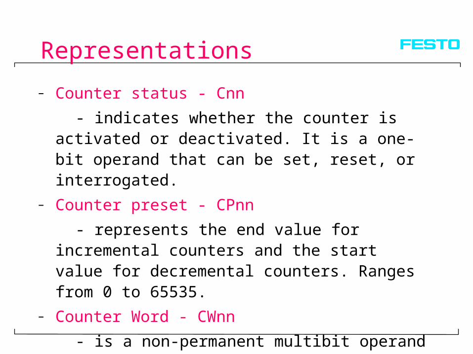
Representations
– Chronological OrderCylinder 1.0 extends and lifts the boxCylinder 2.0 extends and pushes the boxCylinder 1.0 retracts, thenCylinder 2.0 retracts
– Tabular FormWork Step Motion of Cylinder 1.0 Motion of Cylinder 2.0
1 out - 2 - out 3 in - 4 - in

– Abbreviated NotationExtension represented by : + 1.0 +Retraction represented by : - 2.0 +
1.0 - 2.0 -
Representations
– Vector DiagramExtension represented by 1.0Retraction represented by 2.0
1.0
2.0

BASIC RULES IN DESIGNING THE LADDER DIAGRAM 0F SEQUENCE CON TROLS
– 1. The CONTROL CIRCUIT is that part of the ladder diagram which
– processes input signals– 2. The POWER CIRCUIT is that part of the ladder diagram
which– directly controls the output of the PLC– 3. In the Control Circuit, each step in the sequences has
its own – STEP FLAG. A flag is similar to a relay, which can be
turned – on or off and has multiple NO and NC contacts– 4. Each step flag, except the last step flag, employs a
self-holding– circuit.

– 5. A NO contact of the step flag N is in series with the step flag
– N+1. This ensures that the step flags are activated in the correct
– sequence– 6. A NC Contact of the last step flag is in series with the first
step flag– 7. In the power circuit, if an output is activated at step N, a
NO contact– of the step flag is in series with the first step flag– 8. In the power circuit,If an output is deactivated at step N, a
NC – contact of the step flag is in series with the said output.
( except – for double solenoid valves )–
BASIC RULES IN DESIGNING THE LADDER DIAGRAM 0F SEQUENCE CON TROLS

Problem: LIFTING DEVICE FOR PACKAGES
A box arrives at a lifting platform and actuates a proximity sensor S1. It is lifted up by cylinder A, and then pushed onto a second conveyor by cylinder B. Cylinder A retracts. Cylinder B retracts when cylinder A has reached its initial position.


Representations
– Tnn for the timer status (active or inactive)
- shows whether the timer is active or not. It is a one- bit operand than can be set, reset or interrogated. 1 = active, 0 = inactive
– TPnn for the timer preset (preset run-time)
- defines the run-time of the timer given in hundredths of a second and can be in the range 0.00s to 655.35s. The operand for the timer preset is a permanent multi-bit operand and remains stored until a new preset is defined.
– TWnn for the timer word (current run-time)
- is a multi-bit operand and represents the current run-time of the timer.

- allows an output to be activated for a specified time when an input signal is present. It only reacts to the rising edge of the condition. This pulse starts the timer (Tnn=1). The timer preset is loaded into the timer and the timer starts to decrement until it reaches a value of zero, or a further edge (pulse) is detected at the conditional part, restarting the timer, or the timer is reset (Tnn=0).
Rising edge
Start of timer on rising edge
Timer preset
Status of
Condition
Status of
Timer
1
1
0
0
Pulse Timer (Tnn)

Representations
– Counter status - Cnn
- indicates whether the counter is activated or deactivated. It is a one-bit operand that can be set, reset, or interrogated.
– Counter preset - CPnn
- represents the end value for incremental counters and the start value for decremental counters. Ranges from 0 to 65535.
– Counter Word - CWnn
- is a non-permanent multibit operand and indicates the current counter status.


REGISTERS
– Used to store binary, octal or decimal values
– Can be used to perform mathematical functions
– Not addressable on a bit by bit basis

– Loading a value to a register ( executive part )
– Interrogating a register ( conditional part )
– Incrementing( executive part )
– Decrementing ( executive part ) DEC
INC
R4
R50
TO
V0 R1
=V20
R10

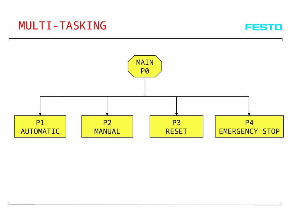
MULTI-TASKING
MAINP0
P1AUTOMATIC
P2MANUAL
P3RESET
P4EMERGENCY STOP

– A program can be activated (started) and deactivated (stopped) from within another program or module.
– The program is activated by setting the operand Pn, and deactivated by resetting it.
– Note: The LDR symbols --( )-- (assignment) and --( / )-- (negated assignment) cannot be used to activate deactivate a program. They are not permissible for the operand P
MULTI-TASKING
PB2
PB1P1
P2
P1
P2
S
S
R
R
P0 = main program

P
U
R
P
U
R
Vacuum Generator
– Workpieces with smooth and Impervious surfaces can be picked up and held (for transporting and assembly) with this vacuum generator
– This produces vacuum in accordance with the venturi principle, using the compressed air from P to R.
– Suction cups are connected to the vacuum port U

– Problem: PICK AND PLACE STATION Sequence of Events:1. Machine in initial position2. Pickup cylinder extends3. Vacuum On -- picks up the workpiece4. Pickup retracts5. Slide to deposit station16. Pickup cylinder extends7. Vacuum off- deposits the workpiece8. Pickup cylinder retracts9. Slide to pickup position