program officer: yapa d. s. rajapakse
TRANSCRIPT

Michelle S. Hoo Fatt Department of Mechanical Engineering College of Engineering Akron, Ohio 44325-3903
Tel: 330-972-6308
Defense Technical Information Center 8725 John J Kingman Road, Ste 0944 F01t Belvoir, VA 22060-6218
Dear Sir/Madam:
Enclosed is the final report for the following grant:
June 29, 2016
Grant Title: Composite Sandwich Structures for Shock Mitigation and Energy Absorption Grant Number: NOOO 14-11-1-0485 Principal Investigator: Michelle S. Hoo Fatt Program Officer: Yapa D. S. Rajapakse Performance Period: 2/14/2011-4/30/2016 (2116-6114 and 7114-4/ 16) Funding Amount: $197,132 ($120K and $77,132)
Please note that the final report covers two periods of performance. Please contact me if you need anything else.
Sincerely,
Michelle Hoo Fatt
Encl: (1)

REPORT DOCUMENTATION PAGE Form Approved
OMB No. 0704-0188
The public reporting burden for this collection of information is estimated to average 1 hour per response, including the time for reviewing instructions, searching existing data sources , gathering and maintaining the data needed, and completing and reviewing the collection of information. Send comments regarding this burden estimate or any other aspect of this collection of information, including suggestions for reducing the burden, to Department of Defense, Washington Headquarters Services, Directorate for Information Operations and Reports (0704-0188) , 1215 Jeffe rson Davis Highway, Suite 1204, Arlington , VA 22202-4302. Respondents should be aware that notwithstanding any other provision of law, no person shall be subject to any penalty for fail ing to comply with a collection of information if it does not display a currently valid OMB control number. PLEASE DO NOT RETURN YOUR FORM TO THE ABOVE ADDRESS.
1. REPORT DATE (00-MM-YYYY) ,2. REPORT TYPE 3. DATES COVERED (From - To)
06/28/2016 Final Report February 2011- April 2016 4. TITLE AND SUBTITLE Sa. CONTRACT NUMBER
Composite Sandwich Structures for Shock Mitigation and Energy Absorption
Sb. GRANT NUMBER
N00014-11 -1-0485
Sc. PROGRAM ELEMENT NUMBER
6. AUTHOR(S) Sd. PROJECT NUMBER
Hoo Fatt, Michelle S.
Se. TASK NUMBER
Sf. WORK UNIT NUMBER
7. PERFORMING ORGANIZATION NAME(S) AND ADDRESS(ES) 8. PERFORMING ORGANIZATION The University of Akron REPORT NUMBER
302 Buchtel Common Akron , OH 44325-0001
9. SPONSORING/MONITORING AGENCY NAME(S) AND ADDRESS(ES) 10. SPONSOR/MONITOR'S ACRONYM(S)
Office of Naval Research ONR One Liberty Center Arlington , VA 22203-1995 11. SPONSOR/MONITOR'S REPORT
NUMBER(S)
12. DISTRIBUTION/AVAILABILITY STATEMENT
Approved fo r publ ic release; distribution is unlimited.
13. SUPPLEMENTARY NOTES
14. ABSTRACT
Analytical models for the blast response of navy composite and composite sandwich structures were developed in this research grant. This report summarizes research spanning two consecutive grant periods of performance: February 2011 to June 201 4 and July 2014 to April 2016. A common theme in the analysis of the blast performance of foam-core, composite sandwich panels was that on a per unit areal weight density basis, lighter and more crushable foam cores offered greater blast resistance and energy absorption than the heavier and stronger foam cores. This was found to be the case even on an absolute weight basis for cuNed sandwich panels and panels subjected to underwater blast.
15. SUBJECT TERMS
composite; foam-core sandwich; blast; pulse buckling ; fluid structure interaction.
16. SECURITY CLASSIFICATION OF: 17. LIMITATION OF
a. REPORT b. ABSTRACT c. THIS PAGE ABSTRACT
u u u uu
18. NUMBER OF PAGES
30
19a. NAME OF RESPONSIBLE PERSON
Michelle S. Hoo Fatt 19b. TELEPHONE NUMBER (Include area code)
(330) 972-6308
Standard Form 298 (Rev. 8/98) Prescribed by ANSI Std . Z39.18

Composite Sandwich Structures for Shock Mitigation and Energy Absorption
Michelle S. Hoo Fatt Department of Mechanical Engineering
The University of Akron Akron, OH 44325-3903
June 28, 2016
Grant Title: Composite Sandwich Structures for Shock Mitigation and Energy Absorption GrantNumber: N00014-11-1-0485 Principal Investigator: Michelle S. Hoo Fatt Program Officer: Yapa D. S. Rajapakse Performance Period: 2/14/2011-4/30/2016
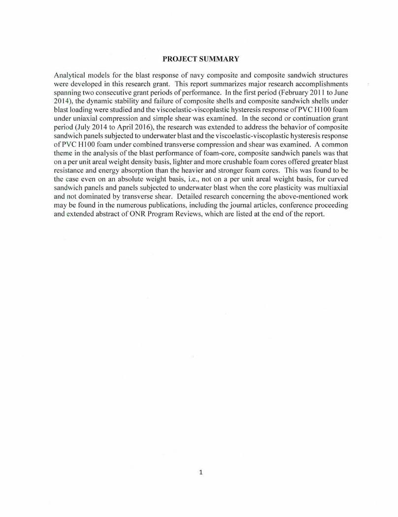
PROJECT SUMMARY
Analytical models for the blast response of navy composite and composite sandwich structures were developed in this research grant. This repmt summarizes major research accomplishments spanning two consecutive grant periods of performance. ln the first period (February 2011 to June 20 14), the dynamic stability and failure of composite shells and composite sandwich shells under blast loading were studied and the viscoelastic-viscoplastic hysteresis response of PVC HI 00 foam under uniaxial compression and simple shear was examined. In the second or continuation grant period (July 2014 to Apri I 20 16), the research was extended to address the behavior of composite sandwich panels subjected to underwater blast and the viscoelastic-viscoplastic hysteresis response of PVC Hl 00 foam under combined transverse compression and shear was examined. A common theme in the analysis of the blast performance of foam-core , composite sandwich panels was that on a per unit areal weight density basis, lighter and more crushable foam cores offered greater blast resistance and energy absorption than the heavier and stronger foam cores. This was found to be the case even on an absolute weight basis, i.e. , not on a per unit areal weight basis, for curved sandwich panels and panels subjected to underwater blast when the core plasticity was multiaxial and not dominated by transverse shear. Detailed research concerning the above-mentioned work may be fbund in the numerous publications, including the journal articles, conference proceeding and extended abstract of ONR Program Reviews, which are listed at the end of the report.
1

LONG-TERM GOAL
The long-term goal of this research is to improve our understanding of the blast performance of navy composites and composite sandwich structures.
OBJECTIVES
Specific objectives of the research were to
• Develop new analytical techniques to address blast response, including the blast mitigation and energy absorption of foam-core composite sandwich plate.s and shells.
• Validate analytical solutions with finite element analysis using ABAQUS and test data, if available.
TECHNICAL APPROACH
Composite sandwich panel theory is based mostly on linear elastic response. This research extended composite sandwich theory by considering the facesheets as anisotropic elastic material and the core as an elastic-plastic material. Damping and energy absorption were incorporated into to the response of a composite sandwich shell under blast loading. Finite element analysis was done to gage the accuracy of the analytical solution. Parametric studies were used to examine the role of the foam in terms of panel blast resistance and energy absorption. ln addition to this, experiments were carried out to better understand the crush behavior and hysteresis of PVC foams.
MAJOR ACCOMPLISHMENTS
The following sections summarizes research findings , and are organized not necessarily in chronological order but rather under subject headings. Detailed analysis and results may be found in the cited references. A common theme in analyzing the blast performance of foam-core, composite sandwich panels is that the lighter and more crushable foam cores offer more blast resi stance and energy absorption than the heavier and stronger foam cores. This is especially true for curved sandwich panels and panels subjected to underwater blast when the core crushes under mu ltiaxial plasticity.
Elastic-Plastic Analysis of Flat Composite Sandwich Panels
ln this research the large deflection, thick composite plate analysis by Wu and Vinson [ l] was used as a basis to determine the dynamic response of a foam-core, composite sandwich panel subjected to blast. Damping and energy absorption of the core were incorporated into to the large amplitude, forced vibration response of a flat composite sandwich panel by modeling the sandwich core as an elastic, perfectly plastic material [2]. Relatively good agreement in predicting the deformation response with FEA was found up to the initial peak deflection of the panel and transverse shear strain in the core. A comparison of the vibration response is given in Figs. I (a) and (b); it is noted that subsequent vibration response do not correlate well due to numerical damping in ABAQUS
2
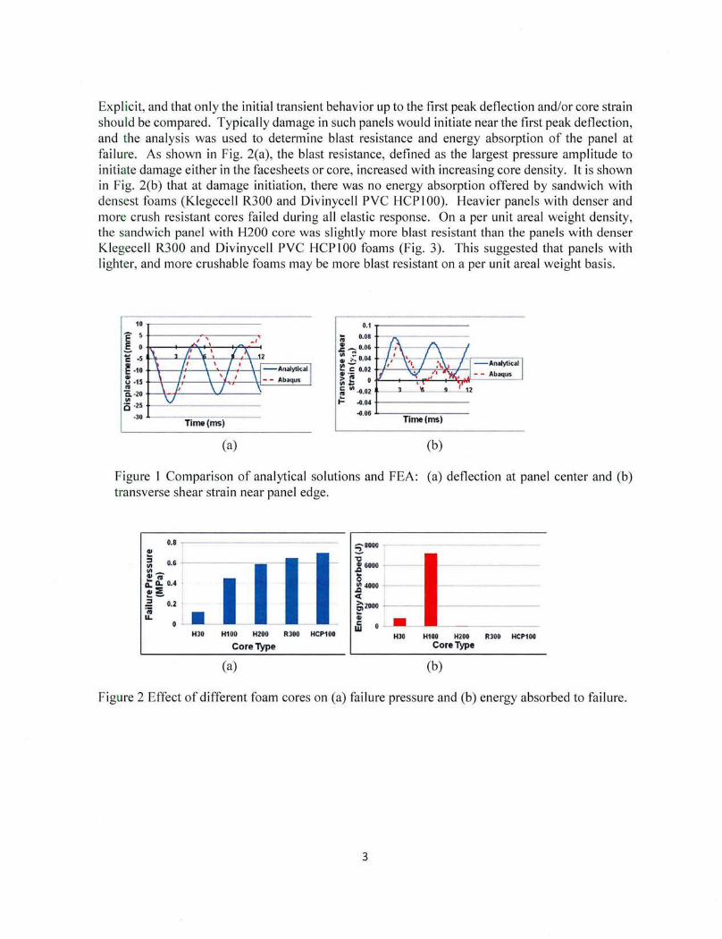
Expl icit, and that only the initial transient behavior up to the first peak deflection and/or core strain shou ld be compared. Typically damage in such panels would initiate near the first peak deflection, and the analysis was used to determine blast resistance and energy absorption of the panel at failu re. As shown in Fig. 2(a), the blast resistance, defined as the largest pressure amplitude to initiate damage either in the facesheets or core, increased with increasing core density. It is shown in Fig. 2(b) that at damage initiation, there was no energy absorption offered by sandwich with densest foams (Kiegecell R300 and Divinycell PVC HCPI 00). Heavier panels with denser and more crush resistant cores failed during all elastic response. On a per unit areal weight density, the sandwich panel with H200 core was slightly more blast resistant than the panels with denser Klegecell R300 and Divinycell PVC HCP I 00 foams (Fig. 3). This suggested that panels with lighter, and more crushable foams may be more blast resistant on a per unit areal weight basis.
(a)
;; 0.08
.! - 0.06
~ ~ 0.04
~ ~ 0.02 ++-....Y..i--+.'\1~'--' ~~ 0¥--+~~~~M---~~ ;
111 ·M2
t:. ·M4 t-------.0.06 .1.--=-----:----
Time(ms)
(b)
Figure l Comparison of analytical solutions and FEA: (a) deflection at panel center and (b) transverse shear strain near panel edge.
0.8 ---------· 41 :; Ill 0.6
"'-~"' II.. II.. 0.4 u.:E ... -.: 0.2 • ·; u.. 0 • •
HJO H100 H200 RJOO HCP100
l~f: ' - ~---_-~_ .. ~_--_ .. ·-_---_-=~=~ ~ aii 0 j_ ·· -- --- - - •• -
HJO H100 H200 R300 HCP100
Core Type Core Type
(a) (b)
Figure 2 Effect of different foam cores on (a) failure pressure and (b) energy absorbed to failure.
3

H30 H100 H200 R300 HCP100
Core Type
Figu re 3 Failure pressure per areal weight density in sandwich panels with various cores.
Foam-Core Cylindrical Sandwich Shells under External Blast
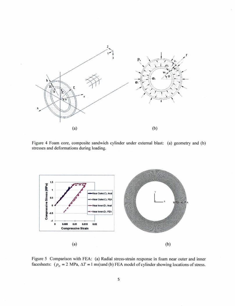
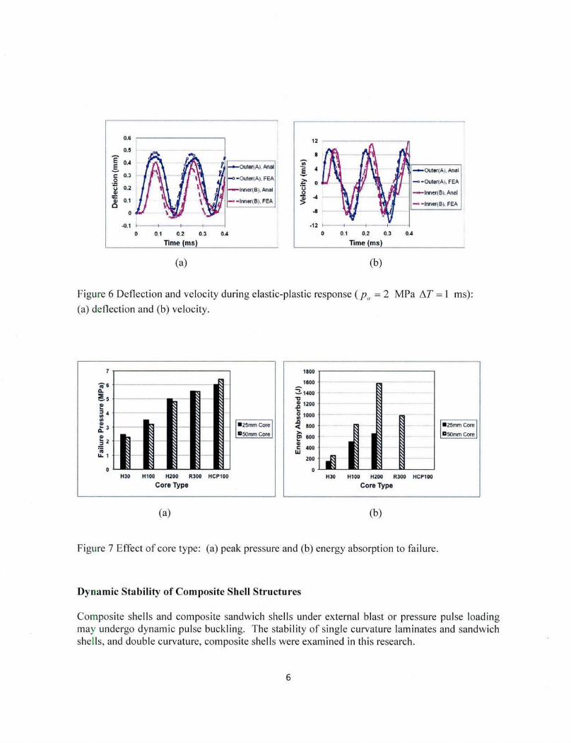
In Ref. [3] the early time, through-thickness stress wave response of a foam-core, composite sandwich cyl indrical shell under external blast (Figs. 4(a) and (b)) was examined. Solutions for the transient response of the facesheets were derived as stress waves propagated through an elasticplast ic, crushable foam core. These solutions were found to be in good agreement with results from finite element analysis (Figs. 5 and 6). The blast response of the composite sandwich cylindrical shell was shown to be affected by the magnitude and duration of the pressure pulse. High amplitude, low duration (impulsive) pressure pulses induced the greatest energy absorption. Low amplitude, long duration pressure pulses caused minimal energy absorption. The amount of energy absorbed increased and the failure load decreased with increasing core thickness. Sandwich shells with foams of vary ing density, compressive modulus and crushing resistance were also examined. As shown in Fig. 7, the sandwich shells with the foam of the highest density, compressive modulus and crushing resistance (Divinycell HCPl 00) were found to be the most blast resistant to failure even though no energy was absorbed by them. Per unit weight, however, the shells with a lighter, less stiff and strong, Divinycell H200 foam core were more blast resistant to fa ilure than shells with a Divinycell HCPl 00 foam core.
4
(a) (b)
Figure 4 Foam core, composite sandwich cylinder under external blast: (a) geometry and (b) stresses and deformations during loading.
1
- NearOUier(C).Anal
--NearOUIOf(C). FEA
- Near lnner!D). Anal
0 o.oos 0.01 0.015 0.02
Compressive Strain
(a) (b)
Figure 5 Comparison with FEA: (a) Radial stress-strain response in foam near outer and inner facesheets : (p0 = 2 MPa, !1T =I ms)and (b) FEA model of cylinder showing locations of stress.
5
E .§. c: 0
·~ q:; Ill 0
0.6
0.~
0.4
0.3
0.2
0.1
0
-0.1 1------l
-o - o uter(AJ. FEA
I - rnner(B). Anal
--rnner(B). FEA
0 0.1 0.2 0.3 0.4
Tlme(ms)
(a)
- Inner( B). An~ l
- • - Inner( B). FEA
-12 1---1 0 0.1 0.2 0.3
Time (ms)
(b)
Figu re 6 Deflection and velocity during e lastic-p lastic response (p0
= 2 MPa !J.T = 1 ms):
(a) deflection and (b) velocity.
~61---------------------~~
Q.
~51-----------·.c~~~-----~1 .. ~41-·-·-······· .. -·--···--···---·~1- .. - ~t - .. ··~ .. 1
£ 3 i-------1~--~~----~---~-l , •• -25_m_m-Co- re', I ., IISOmm Core I ~2i~~---~~----~l-~t--•~-l
·;; ~1i~~--~~---~l--~~---~~-l
HJO H100 H200 RJOO HCP100
Core Type
(a)
1800 .,-------------,
1600
5:1400 "C 1: 1200
~ 1000 J:l < 800 >. !:> 600 -.. c 400 w
200 ~
H30 H1 00 H200 RJOO HCP1 00
Core Type
(b)
Figure 7 Effect of core type: (a) peak pressure and (b) energy absorption to failure .
Dynamic Stability of Composite Shell Structures
Composite shells and composite sandwich shel ls under external blast or pressure pulse loading may undergo dynamic pulse buckling. The stabi li ty of single curvature laminates and sandwich shells , and double curvature, composite shells were examined in th is research.
6

A. Single Curvature, Composite Laminated Shells
Dynamic pulse buckling of a single curvature composite shell under external pressure (Fig. 8) was examined using Lagrange' s equation of motion and the Budiansky-Roth criterion in Ref. [4]. As shown in Fig. 9, the predicted transient shell response compared very well with results from ABAQUS Implicit. The predicted buckling loads also agreed with experiments on steel arches (Fig. 1 0) . Load duration determined whether the buckling was impulsive, dynamic or quasidynamic. Thicker composite shells were more likely to fail by first-ply failure rather than buckling. It was shown that the composite lay-up could be adjusted to increase the buckling resi stance of the shell.
Figure 8 Single curvature, composite shell subjected to external pressure pulse loading.
7

.... 0.006 c: <II
A E <II u 0.004 IU c. "' 0
0.002 lii :a IU a: "'C <II
.!::! lii E -11.oo2 0 z
-11.004 0 20 40 GO 80 100 120 140 160
Normalized Step Time
Figure 9 Comparison of FEA and analytical solutions for (,; at shell center, 80 = 1r I 3 .
100
Nl " "-N -"=1 ~ ~
~ .::
II 10 ,_ Qj
~ ~ 10
!l. Q)
.!!l ::J c. .s
0 .1
I •
- • ~ • v
~ lii O
0
@jl 0 @
0
• • II'" 0
EJ<peri mental Data
(Humphreys, 1965)
• Buckled
e Marginal Case
o Unbuckled
--ft-- Predicted Results
10 20 30 40 9 2 a Shape Parameter y = -!;;-
Figure 10 Comparison of predicted buckling load with experimental results on .steel arches (Humphreys, 1965 [5]).
B. Single Curvature, Composite Sandwich Shell
An elastic-plast ic model was developed for predicting the blast response of a foam -core, single curvature, composite sandwich panel , which is shown in Fig. II [6]. A multi-layered approach was used to distinguish facesheets and core deformations . Core compressibility and transverse shear through the thickness were accounted for using linear displacement fields through the
8
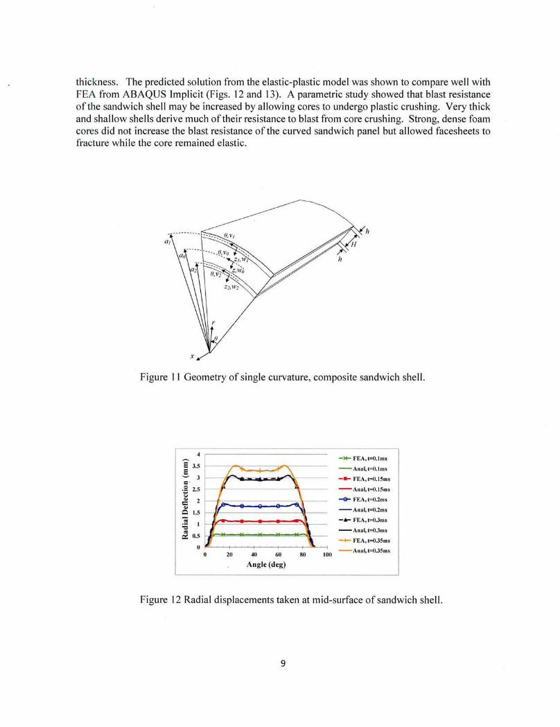
thickness. The predicted solution from the elastic-plastic model was shown to compare well with FEA from ABAQUS Implicit (Figs. 12 and 13). A parametric study showed that blast resistance of the sandwich shell may be increased by allowing cores to undergo plastic crushing. Very thick and shallow shells derive much of their resistance to blast from core crushing. Strong, dense foam cores did not increase the blast resistance of the curved sandwich panel but allowed facesheets to fracture while the core remained elastic.
h
Figure 11 Geometry of single curvature, composite sandwich shell.
,-------·---·---·----------, 4 ,----·
~ 3.5 1-r~~::::-;;r~--; 3 1-----t;F..._,&;;jjjj~;ji~;;=M""""i~--
._g 2.5 f---iJ'.-------4,----Col .. r:: .. Q 1.5
~ I :
a! 0.5 1--.ll""*"""""'*"""""*""'~e......""*"""',l:--~I
0 zo 40 60 80 100
Angle (deg)
-*' FEA,t=O.lms
- Anal,t=O.tms
-- FEA,t=O.I5ms
- Anal,t=O.I5ms
-EI- FEA, t=O.Zms
- Ana l, t=O.Zms
-~ FEA, t=0.3ms
-Anal,t=0.3ms
-+- FEA, t=0.35ms
- Anal, t=0.35ms
Figure 12 Radial displacements taken at mid-surface of sandwich shell.
9

3
'\
2 ,,,- -~ FEA , CTr
~ - Arwi, CTr "' p... I
J .... \
-@- F EA , CTfl ~ ~ "' 0
~f.. ...,__ _~ - A nai, CT11
"" ~ ->+- F EA, Trll "" ,_ -I
ci5 · ~ -Annl, Tr~~
-2 W- V ' -- FEA, U:r
-3 ~~-t---'--"-"-'-·-1---'--·'--'-t·~~ .... ~--····-t
-An~li, CTx
0 20 40 60 80 100
Angle (dcg)
Figure 13 Stress variations along the mid-surface of core at t= 0.13ms, right before core yie lding.
C. Double Curvature, Composite Shells
For the study of buckling of a doub le curvature, composite shell under pressure pulse loading (Fig. 14), Novozhilov nonlinear shell theory was used to capture the large deformation response ofthe shell under an exponentially decaying pressure pulse [7]. The shell was assumed to be fully clamped, as in practical applications. Equations of motion were derived using a Lagrangian approach. Some of the key challenges ofthis work included the coupling of nonlinear differential equations because of non-orthogonal transverse deflection modes, which made solving equations of motion rather computationally challenging. As shown in Figs . 15 and 16, the buckling strength of a doubly-curved shell may be increased by increasing the angular extent or making the shell deeper, thereby triggering instability of higher buckling modes.
I I
Figure 14 Double curvature shel l subjected to external pressure pulse loading.
10

1000 Rtlr=15SA fixed
I 1 --•ih=S5.3, 20 deg
100
• \ -+- aih=ll0.6, 40 deg .... ..... aih•22L2, 80 deg
~ 10
~~ ... <I I ~ "-.... ......... _.....
-0.1
().{)[ OJ I 10 100 l cr (kPa-s)
(a) (b)
Figure 15 Woven E-Giass, Vi nyl Ester shell with fixed rad ius of curvature (R/h= l 58.4) and various span (angular extent changes with span): (a) shell geometry and (b) cri tica l buckli ng curves.
10000 ath-1Hl.6 fixed
1000
I ' Uo
-;?00
I \ / ~\ -.- ~ 10 h,IL, ~-<\.\
\~ \ u • I
I ""· ~· I '<\ 0.1
__L 0.01 {)JJI 0.1 I lQ 100 1000
lor (kPa-s)
(a) (b)
Figure 16 Woven E-Giass, Vinyl Ester shell with fixed span (a/h= l1 0.6) and various rad ius of curvature (angular extent changes with radius of curvature): (a) she ll geometry and (b) critical buckling curves .
M ulti-Layered Ana lysis of Composite Sandwich Shells
Unl ike the prev ious model that were deve loped earlier for the flat sandw ich panels, a mul ti -l ayered sandwich panel approach was used to better characterize the stress state in the foam core . Curved sandw ich panels typically carry higher loads and are more effic ient than flat panels because res istive mem brane forces are induced by their ini tial curvature, in add ition to shear forces and bending moments. Foam p lasticity would therefore resul ts from a multiax ia l stress state, both inp lane compression and transverse shear, in a curved sandwich pane l. Thi s is in contrast to a flat sandwich panel, in which the foam is dominated by transverse shear stress.
11

A. Single Curvature, Sandwich Shells
A solution for the blast behavior of a single-curvature composite sandwich shell with elastic-plastic core crushing (Fig. 17) was developed [7]. This solution follows from research by Gao and Hoo Fatt [4] on thin composite shells undergoing dynamic pressure pulse buckling.
h
,'(
Figure 17 Geometry of single curvature, composite sandwich shell.
Predicted solutions of the transient deflection and effective yield stress at core mid-surface, assuming isotropic crushable foam model , compared well with FEA results (see Figs. 18(a) and (b)) . A parametric study showed that blast resistance of the sandwich shell is increased by allowing cores to undergo plastic crushing (see Figs. 19(a) and (b)). Strong, dense foam cores do not increase the blast resistance in a curved sandwich panel. Other parametric studies showed: (1) thick and shallow sandwich shells derive most of their strength from core crushing, and (2) shells with strong cores and very thin facesheets are susceptible to local pulse buckling or facesheet wrinkling.
12

5 3.5 E ';:' j
0 'G 2.5
<.1
" c 2
Q I' - .>
" :tj I
" a: 0.5 i
I
-- FEA, t=O.I ms
L - - ~ ·-·-I I \
- Anal,t=O.I ms
-- FEA, t=O.J5ms
- Anal,t=0.15ms
-- FEA, t=0.2ms
f{ " - Anal, t=0.2ms
-- FEA,t=O.Jms
' - Anal, t=O.Jms
\ -- FEA, t=O.JSms
20 -10 60 SO IOO - Anal, t=O.JSms
Angle(dcg)
(a)
5
~ ( ~ ~ ~ 3 ~
cii 2.5
" 2 ·E
<.1 1.5
~ I t.J
0.5
0
Plastic zones
v ~\1 -- FEA, t=O.Ims --.... ~
1i "A ( fiW \ - Annl, t=O.I ms
I I 17\.('.., - - , ~- I _L - - FEA, t-=O. ISms
-- --- ..., - Anal, t=O. ISms
\1\..,. 2M_ _1 - - FEA, t=0.2ms
- Annl, t=0.2ms \ \ " y
v I I \ v .. ., j _ - - FEA, t:O.Jms
_\ I - Annl, t=O.Jms
• - - FEA, t=0.35ms
0 20 40 60 80 100- Anal, t=O.JSms
Angle(dcg)
(b)
Figure 18 Comparison of predi cted and FEA resul ts at mid-plane of foam core: (a) rad ia l d isplacement and (b) effective stress for plastici ty.
2.5 Most blast 250 Ci)<- resistant
,.-., 01 2 .::;-200 ----·-···-··- ------------------c. • Foam :; ""' • Foam '-' failure ~ 150 fai lure ., 1.5 .. Q
= • Facesheet ~ "' "' 1 .. 100 .. _ -- -- --------. Facesheet .. fracture .. :::: c. .,
fracture 01 ~ 0.5 -~- -- 1----- 1--- --- c::: 50 Purely = Q -k"' elastic :;
0 "' 0 H30 H100 H200 R 300 HCP H30 H100 H200 R .
Core type 100 Core type 100
(a) (b)
Figure 19 Curved sandwich panels with vanous cores: (a) blast resistance and (b) energy absorption.
B. Double Curvature, Sandwich Shells
In Ref. [8] , a multi -layered sandwich shell model incorporating elastic-p lastic core response was developed for a double curvature, sandwich shell under blast (Fig. 20). Transient deflection and effective yie ld stress at core mid-surface, assumi ng isotrop ic crushab le foam model, were fo und to be in good agreement with FEA (see Figs. 21(a) and (b)) . Due to shell curvature, core mid-
13

surface in-plane stresses are on the order of out-of-plane stress (Figs. 22 (a) and (b)), and this indicated that the core should be modeled as transversely isotropic instead of isotropic.
Figure 20 Geometry and loading of double curvature sandwich shell.
-0.5 t-lk""'o-----'"11'--
I - 1 t-'\~~-;;:;;;;;7 ; -1.5 ·t---1l'l.-----n.
= :: -2 +---~...,___,-# c 0 -2.5
-3 ·F----"~£_ __ _
-3.5 L---::---,----Spao(mm)
(a)
-- FIA_O.lms
- A••_O.lSms
- - FIA_0.15ms
- Aa•_0.2ms
- - FEA_O.lau
- Aa•_0.25ms
- - F£A_0.2Sms
- A .. _0.1ms
- - FEA_0.1ms
- A••_o.I5 .. ,
- - FIA_0.15oas
- Au_0.2ms
- - .FL<\_0.2 ms
- A .. _0.25ms
0 "TTTT-t..,."T""T...-+-rrrr+rrn-h-n-r - - FIA_0.25 ms
50 100 150 200 250
Spao (mm)
(b)
Figure 21 Comparison of results from analytical model and FEA, assuming isotropic crushable foam: (a) transient deflections and effective stress in core mid-surface.
14

0 4
0 50 100 150 200 250 - Aaa_Sll - Aaa_S33 -0.2 .
"i' -- FEA_Sll
~ -0.4 , - Aaa_S22
"i' 2 t------.Jl ~
~ 1 -f-------IJ'-----1-
-- FEA_S33
- Aoa_Sl3 M
-0.6 .. -- FEA_S22 " l:
- - FEA_S13
:IJ -0.8 - Aaa_Sl2 - Aaa_S23
-1 -- FEA_Sl2 -J -- FEA_S2J \.
-1.2 Span{mm)
-4 .L....C ______ _
Spao{mm)
(a) (b)
Figure 22 Stress distribut ion in foam mid-plane along y=bo/2 and at t=0.16 ms: (a) in-plane stress components and (b) out-of-plane stress components.
The elastic-plastic sandwich shell model was extended to incorporate a transversely isotropic TsaiWu core yield criterion. A comparison of the plastic yield zones produced by the isotropic crushable foam and Tsai-Wu criteria may be seen in Fig. 23 . Yielding occurred earlier in the case of the isotropic crushable foam criterion, but the panel took a longer time to reach maximum deflection assuming transversely isotropic properties and the Tsai -Wu criterion. The sandwich she ll deflections were found to be 27% higher assuming transversely isotropic Tsai-Wu yielding instead of isotropic crushable foam yielding. Panel failure loads were also over-predicted by about I 0 % with the isotropic crushable foam model as compared to the transversely isotropic Tsai-Wu fail ure criterion.
Crushable Foam
H "-'" -=-----::;;-::-iA-- - O.lms
"' " t; 0.6 +ff--\--\--\---,f--1--;1--11-u
f:; 0.4 -tlr --\-1H rl.--+-+-+H
0.2 .... ~.-...~~~h~--l
50 100 150 200 25 0
Span (mm)
(b)
- 0.15ms
- 0.2ms
- 0.25ms
1.2
::.. I .. -.f.! 0.8 c
: 0.6
~ 0.4 " f:; 0.2
Tsai-Wn
- O.lms
- O.!Sms
- 0.2ms
- 0.25 ms
- 0.27ms
50 100 150 200 250 (a) Span (mm)
Figure 23 Distribution offailure index in core mid-surface (F=l denotes yielding and plastic zone): (a) isotropic crushable foam and (b) transversely isotropic Tsai -Wu foam.
A parametric study indicated that the blast resistance of the sandwich shells increased as the curvature ratio decreased because of greater transverse loads through the action of membrane
15

compression (Fig. 24). Sandwich shells with the isotropic core failed at higher pressures sandwich shells with transversely isotropic core, and this became more apparent with decreasing shell radius of curvature. This not only indicated the importance of using the correct in-plane foam properties for some shell configurations but it also implied that modeling the core of the sandwich shell as isotropic would give non-conservative estimates of the structure's ability to resist blast loading.
0 10 20 30 40 50 60
Rofhtot
~Isotropic
core
~Trans
Isotropic core
Figure 24 Variation of failure pressure (blast resistance) with sandwich shell curvature ratio (shell becomes flat panel as radius-to-thickness ratio increases).
Water Blast Response of Foam-Core Composite Sandwich Panels
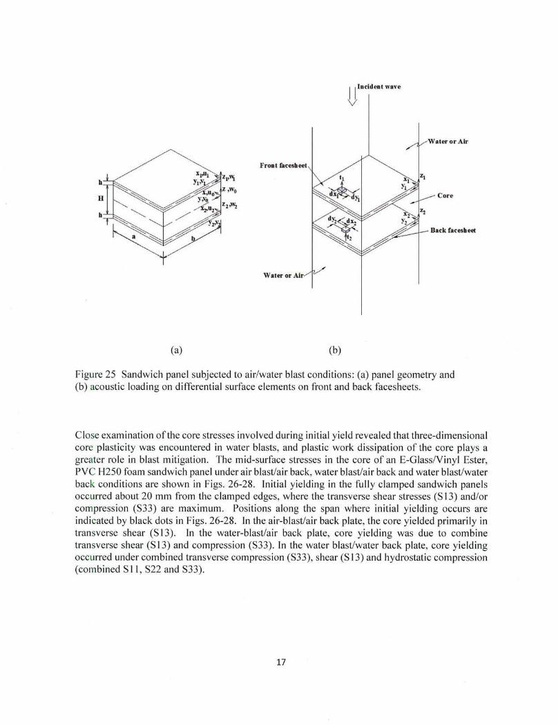
A fl uid-structure interaction model [9] was developed to examine the dynamic response of clamped composite sandwich panels subjected to air blast/air back, water blast/water back and water blast/water back conditions (Fig. 25). This was done by combining Taylor's fluid-structure interaction model for underwater blast pressure on plates [I 0] and a multi-layered, elastic-plastic sandwich panel model developed earlier [8]. It was found that fluid damping terms substantially reduced and slowed down deformations of the sandwich plate. This caused higher pressures induce damage in the water blast/air back and water blast/ water back panels. A parametric study on the influence of core properties in Fig. 26(a) further indicated that softer, more ductile foam core sandwich structures offered greater survivability of composite sandwich panels subjected to water blasts. Plastic core crushing and the associated work dissipation was recognized as an impo1tant mechanism for the increased blast resistance, as shown in Fig. 27(b ).
16
II Iocideot wal'e
v
Front facesbeet
Core
Water or Air
(a) (b)
Figure 25 Sandwich panel subjected to air/water blast conditions: (a) panel geometry and (b) acoustic loading on differential surface elements on front and back facesheets.
Close examination of the core stresses involved during initial yield revealed that three-dimensional core plasticity was encountered in water blasts, and plastic work dissipation of the core plays a greater role in blast mitigation. The mid-surface stresses in the core of an E-Giass/Vinyl Ester, PVC H250 foam sandwich panel under air blast/air back, water blast/air back and water blast/water back conditions are shown in Figs. 26-28. Initial yielding in the fully clamped sandwich panels occurred about 20 mm from the clamped edges, where the transverse shear stresses (S 13) and/or compression (S33) are maximum . Positions along the span where initial yielding occurs are indicated by black dots in Figs. 26-28. In the air-blast/air back plate, the core yielded primarily in transverse shear (S 13). In the water-blast/air back plate, core yielding was due to combine transverse shear (S 13) and compression (S33). ln the water blast/water back plate, core yielding occurred under combined transverse compression (S33), shear (S 13) and hydrostatic compression (combined S II , S22 and S33).
17

Iii 30000 Q)
<~ 25000
"it 'Vi 20000 ;; ~ "'"tl 15000 ~.., .. .r::. c.. Ill) 10000 Q) 'iii ;; ~ 5000 'iii lL 0
Plates with PVCH200 foam most blast resistance in water blasts.
J • Air blast/
Air back
!:! Water blast/ Air back
I Water blast/
11 1 I I I Water bliCk
H30 H100 H200 H250 HCP100
Foam type
(a)
More core plasticity in water blast.
50 I
"' • Air blast/
40 Air back
~
~30 !'.l Water blast/ 0 3: ~
Air back .~20
"' ~ ~ I Ill I Wator blast/ 11: 10
~ d ~ Water back 0
H30 H100 H200 H250 HCPlOO Foam type
(b)
Figure 26 Comparison of (a) blast resistance and (b) plastic work dissipation up to failure for several panels with E-Giass/Vinyl Ester facesheets and different cores.
5 4 3
-2 ~ 1 !o ~ -1 ! -2 .:;; -3
-4 -5
·-ccn;on frnrnl
A
50 100 1 50 200 25
(a)
- 511
~522
- 512
5 4 3
- 2 ~ 1 !o .. -1 !! -2 .:;; -3
-4 -5
_,, L
/ - 513 ....... L _, ~ -.
5()" 100 1 50 200 2 50- 523
- 533 / "'"""nun) ~,_,
(b)
Figu re 27 Core mid-surface stresses at the onset of yielding in air blast/air back: (a) in-plane stresses and (b) out-of-plane stresses
5 .----------------4 -+----------------3 ~---------------
- 2 +---------------.. -~ 1 ~--------~~.nun)
::E 0 ?~~':!~=~~~ - S11 i -1 :H.J .lUV Do-2"0{/2"5C\....-522 ! -2 i:ii-3 - 512
-4 ~----------------5 -"-----------------
(a)
5 4 3
- 2 ~ 1 !o = -1 ! -2 ~ -3
-4 -5
~
.L~ /
.f ~ ..,. ......... __,.
':J, .lUU .l ':JU LVU iS / m;~n.lmmJ ......
(b)
- 513
o-s23
- 533
Figure 28 Core mid-surface stresses at the onset of yielding in water blast/air back: (a) in-plane stresses and (b) out-of-plane stresses.
18

5 4
_3 ~ 2 :!: 1 ';;o ~ -1 ~-2
- 3 -4 -5
-
soan mm) - Sll
~u :w u :t::>u L~
(a)
0- s22
- S1 2
5 4 3
- 2 ~ 1 ~0 ~ -1 !! -2 ~ -3
-4 -5
span[m~· /
/
S13
- S23
L..s33 !t"' :>U .lUU .l :>U ..!VU LfJ. t\ I
'\. J
(b)
Figure 29 Core mid-surface stresses at the onset of yielding in water blast/water back: (a) in-plane stresses and (b) out-of-plane stresses.
Hysteresis Response of Foam
In order to examine the full potential of polymeric foams in terms of energy absorption, one must be able to characterize the behavior of the foam beyond initial yield and crushing of cells. Cyclic hysteresis experiments were conducted on Divinycell PVC Hl 00 foams under uniaxial compression and simple shear [II , 12], and more recently these tests were extended to combined transverse compression and shear using angled specimens [13].
A. Hysteresis in Uniaxial Compression and Simple Shear
Uniaxial compression
An MTS 831 servo-hydraulic machine was used to determine stress-strain curves of the PVC HI 00 foam using the apparatus shown in Fig. 30. The I inx I inx I in cubic specimen was glued to aluminium grips so that displacements can be applied in both directions. A comparison ofthe outof-plane and in-plane hysteresis in PVC HI 00 foam is shown in Figs. 31 and 32. The foam was stiffer in the out-of-plane direction than in the in-plane direction , but exhibited similar behavior in both directions . The foam was characterized as being elastic-plastic and hysteretic. It was also rate-dependent, as shown in Figs. 31 (a) and (b). The amount of hysteresis or energy absorption increases with strain amplitude as shown in Figs. 32(a) and (b).
19

Actuator Pair of tiC'' Clamp
PVC HlOO Specimen
Load Cell
Figu re 30 Setup for cyclic <C(•mpression tests .
Strain•0.10
400
300
- Straio rate• J.OC\15 1is ' 200 - Straluateoll.0050 1Js
100 - Str:oi nrate-1>.0500 1/s
- Str>io rote•0.5000 •.Js
- Strah rate...S.OIOO ~ Is
0.1
·100 Compressive Strain
·200
(a)
25l
- '200 .. "' i 150 .. ~- 100
• , l 50
• Ci. 0 E • v ·50
-lC<l
Strain Amp. =0.10
(b)
rate:O.D0051/s
_ - ·omnn rate=0.0050 1/s
rato=o.osoo 1/s
rate:0.5000 1/s
rate:5.0000 1/ s
Figure 31 Compressive stress-stra in cun;es at strai:l amplitude of 0.1 0 and various strain rates : (a) out-of-p lane and (b) in-plane.
20

400 110
~ 300 zoo
;; ! 110 a :: 200 .
- StrainAmp.=0.02 . .. • !l - Strain Amp . .0.04 u 100 .. - ltralnAmp.•O.OZ
- ltraln Anlp.•0.04
~ 100 - Strain Amp.-o.06 • . ;; ;; 10 - StnMnAmp.-o.oa . .. • f 0 -St111inAmp .~.10 ~ Q,
0.08 0.1 E 0 E 0 0 u (J -100 -10
- ltrai1Amp.•0.06
- stralnAmp.•O.os
- ltrailAmp.•O.lO
ComprRssive strain
-200 ·100
(a) (b)
Figure 32 Compress ive stress-strain curve at a strain rate of0.5 s- 1 with various strain amplitudes : (a) out-of-plane and (b) in-plane.
Simp le Shear
The apparatus shown in Fig. 33 was constructed to determine cyclic, out-of-p lane and in-plane, shear response of the PVC HI 00 foam. The foam spec imen was a 6inx I inx0.5 in block, which is about half the size of a standard shear specimen. Figures 34 and 35 show the shear stress-strain response of the foam in the out-of-plane and in-plane directions. As in the case of compress ion , the foam was stiffer in the out-of-plane direction. The shear response was very similar to the compression response in that the foam yielded, exhibited plastic flow, and underwent hysteresis. It was rate-dependent and the amount of hysteresis increased with strain amplitude .
21

Ball Bearing
Aluminum Plates
Specimen
MTS Actuator
Load Cell
Figure 33 Setup for cyclic pure shear tests.
22

350 250 300
250 200
'; 200 - Strain rata=0.0005 1/s i 150 - Strain rata=0.0005 1/s .s
- Strain rata=0.0050 1/s .s - Strain rata=0.0050 1/s " 150 .. 100 ! 100 - Strain rata=O.OSOO 1/s ! - Strain ra1e=0.0500 1/s en 0 50 - Strain rate=0.5000 1/s - 50 - Strain rate=O.SOOO 1/s -" " • • - Strain rate=S.OOOO 1/s J: 0 - Strain rate=S.OOOO 1/s J: 0 en en
-50
-100 -50
-150 -100
(a) (b)
Figu re 34 Simple shear stress-strain curves at a strain amp li tude of0.2 and various strain rates: (a) out-of-plane and (b) in-plane.
350 .------------
300 1------ -:-::::;;;;;;;;;o=---:r
250 1-----7'
£ 200 1---
; 150 b ~ 100 ; ; 50
-50
-100
(a)
- StrainAmp.=0.04
- S1rainAmp.=O.OB
-Sir~n Amp.=0.12
- Strain Amp.=0.16
- StrainAmp.=0.20
250 ,----- --------
j 100
; 50 .c Cl) 0
-50
-100
- Sirain Amp.=0.04
'----- - SirainAmp.=O.OB
- Sirain Amp.=0.12
~·'------- -Sir~n Amp.= 0. 1 6
- Sirain Amp.=0.20 ~.q--r--~--+
(b)
Figu re 35 Simple shear stress-strain curves at a strain rate of0.5 s· 1 and various strain amplitudes: (a) out-of-plane and (b) in-plane.
B. A Viscoelastic-Damage Model for Compression Hysteresis
A phenomenological constitutive model for Divinycell PVC H 100 foam undergoing crushing and hysteresis under cyclic compression loading was developed [ 12]. The model shown in Fig. 36 was used to describe strain rate-dependency, damage and hysteresis of PVC H 100 foam. A simple damage initiation criterion based on critical compressive strain was proposed to separate undamaged and damaged foam response. The standard model , an elastic spring in parallel with Maxwell element, was used to describe viscoelastic behavior before and after damage. Before
23

damage, spring and damper constants were evaluated from the test data. The rate-dependent undamaged stress-strain response and flow stress were found to be in good agreement with test results. After damage, the spring and dashpot resistances were found to be functions of strain amp litude and flow stress, which depended on strain rate. These viscoelastic damage functions were shown to give very good predictions of the hysteresis and strain rate-dependent behavior of the foam after damage (Figs. 37 and 38) .
.....----- € ----+'
-+ I I
(a) (b)
Figure 36 Material models for the viscoelastic damage: (a) before damage and (b) after damage.
3
~ 2.5 +---~.-4'-:----">.--.p--cr;-~:;-;-;:;-;-:-:-:--~r---------, .,
~ !====~~~~~~~~;;~ill ~ 2
::: 1.5
x Test, 0.00051/s
i t-~~~~~~~~~ -~ 0_5 +--?fu::lo/Wi' p~:.::..:..___,,A..~~~--
o Test, 0.051/s
CII
f 0 +-:':-~'7A~~Itf ~-~~_;__,_+--'--L...L---'-+ c.. ~ -0 .5 .:d~~ ii"""=-----------
0 -1 <f'7'~"'-----------'---------'l
-1.5 -'---------------
Figure 37 Comparison of simulated curves and test data at various strain rates and a fixed strain amplitude of 0.1.
24

·-·------------------------------·---------·---·-···---·1
nr t en en Ql .t:l en Ql > iii en Ql ... c. E 0 0
2.5 .,.-------·--------
2
1.5
0.5
0
-1 -~~~~~-~~~~-~-~~--'---+
0 0.02 0.04 0.06 0.08
Compressive strain
j~
x Test, Emax=0.10
- Pred., Emax=0.1 0
A Test, Emax=0.08
- Pred., Emax=0.08
:t: Test, Emax=0.06
-Pred., Emax=0.06
A Test, Emax=0.04
- Pred.,emax=0.04
+ Test, Emax=0.02
0.1 -Pred., Emax=0.02
I
Figure 38 Comparison of simulated curves and test data at various strain amplitudes and a fixed strain rate of 0.0005 s- 1
•
C. Hysteresis under Combined Compression and Shear
Cyclic hysteresis experiments were conducted on Divinycell PVC HI 00 foams under combined transverse compression and shear using angled specimens, as shown in Fig. 39. The specimen was bonded to test fixture so that it could experience tension after permanent deformation. By adjusting the angle B, one could obtain cyclic stress-strain curves for a variety of compression and shear
stress states.
T Displacement-control
Figure 39 Test setup for combined cyclic compression and shear.
25

Figures 40(a) and (b) show the compressive stress-strain and shear stress-strain responses obtained from the 60 deg angle specimen. As in previous uniaxial compression and pure shear experiments [10,11], a large amount of energy was dissipated by the core due to plastic yielding followed by hysteresis. For a fixed displacement amplitude, rate-dependent behavior is observed in Figs. 41 (a) and (b).
'" Equivalent Strain Rate=0.004 s-1 for 9 = so•
0 .8 .,..---------
~ 0 .6 t--:;;;.;p;;;_j~f:::j·-..,. 0 .4 +-#-:ttl ..
V1
~ 0 .2
"' ~ 0 ·Bi -o.z :r--------w ~ -o.4 -1--'-~-'-+~.._._t--'-'-'--'-t E 8
0 0.0 2 Oc04 0 .06
Compressive St rain
(a)
- 1.02mm
- 1.52mm
- 2.03mm
- 2.54mm
Equiva lent Strain Rate=0.004 s·1 for 9 = so•
0 0 .0 2 0.0 4 0 .06 0 .08 0 .1
Shear Strain
(b)
- 1.02mm
- 1.52mm
- 2.03mm
- 2.54 mm
Figure 40 Cyclic stress-strain curves from () = 60 deg test under varying displacement amplitudes: (a) compression and (b) shear.
Displacement = 2.54 mm for 9 = 60' I 0 .8 ...---------
L~iiiiii!ir - 0.0{)041/s -; 0 .6 l ~ - 0.004 1/s .. 0 .4 3---1-----:
"' 1 0 .2 -1-#--:;o.- - 0.04 1/ s
~ 0 +j~,. ... :l...-'-t--'-'-'-'-1 K ~ . E -{).2 "P:__.u_o.u..___,_...._...___u.:vo_ 4 1/s
- 0.41/s
8 -{).4 -'---------Compressive Strain
(a)
Displacement = 2.54 mm for 9 = 50'
... ~0.5 1--J~---::: ... "' .. ; 0 ~~-... "-1-'-''-'-'-t-'-'-'--'-1 .... "'
Shear Strain
(b)
- 0.0004 1/ s
- 0.004 1/ s
- 0.04 1/s
- 0.41/ s
Figure 41 Cyclic stress-strain curves from () = 60deg test under varying strain rates: (a) compression and (b) shear.
Ini tial yielding of the bonded foam was more accurately determined by Tsai-Wu yield criterion than the commonly-used isotropic yield criterion (see Fig. 42). The Tsai-Wu criterion is being used to define equivalent stress, strain and strain rate in a multi-axial viscoelastic damage model.
26

ia 1 +-.....3o.....-------c... ! 0.8 T-----T-------::: ~K Test a~ o.6 ¥"---"""-''i~'------
z - Tsai-Wu ~ 0.4 T------+-"""~---Gl - Isotropic
..1: 0.2 +------t----+---VI
0 0.5 1 1.5 2 2.5
Compressive Stress (MPa)
Figure 42 Yield criterion for PVC HI 00 foam.
IMP ACT OF RESEARCH/TRANSITIONS
Lightweight, composite sandwich structures offer significant benefits to navy combat vessels. Structural weight savings allow increased payload for artillery and/or power generation for modern-day weaponry such as lasers. Polymer matrix composites and foams offer reduced magnetic, radar and sonar signatures, which are important for stealth technology. The ability of navy ships to survive blast loading through the use of foam core hulls and superstructures was investigated this research. Results from this grant also expand the state-of-the-att in modeling foam material behavior specifically for applications involving blast mitigation.
REFERENCES
[I] Wu, C.-l. and Vinson, J.R. , "On the Nonlinear Oscillations of Plates Composed of Composite Materials," Journal ofComposite Materials ; 3(1):548-561 , 1969.
[2] Hoo Fatt, M.S. and Chapagain, P. , "Pressure Pulse Response of Composite Sandwich Panels with Plastic Core Damping," Journal of Sandwich Structures and Materials; 14(4): 392-429, 2012.
[3] Hoo Fatt, M.S. and Surabhi , H., "Blast Resistance and Energy Absorption of Foam-Core Cylindrical Sandwich Shells under External Blast," Composite Structures; 94: 3 L 74- 3185 , 2012.
[4] Gao, Y. and Hoo Fatt, M.S. , "Dynamic Pulse Buckling of Single Curvature Composite Shells under External Blast," Thin-Wal led Structures; 52: 149-157, 2012.
[5] Humphreys, J.S. , "On dynamic snap buckling of shallow arches," AlAA Journal ; 4: 878-886, 1965.
[6] Gao, Y. and Hoo Fatt, M.S. , "Local Facesheet Pulse Buckling in a Curved, Composite Sandwich Panel," Composite Structures; I 04: 249- 260, 2013.
[7] Sirivolu , D. and Hoo Fatt, M.S. , "Dynamic Stability of Double-Curvature Composite Shells under External Blast," International Journal ofNonlinear Mechanics ; 77: 28 L -290, 2015.
[8] Hoo Fatt, M.S. and Sirivolu, D. , "Blast Response of Double Curvature, Composite Sandwich Shallow Shells," Engineering Structures; 100:696- 706, 2015.
27

[9] Hoo Fatt, M.S. and Sirivolu, D., "A Fluid-Solid Model for Composite Sandwich Plates under Water Blast," in the Proceedings of the 20111 International Conference on Composite Materials, Copenhagen, Denmark, July 19-24, 2015.
[I 0] Taylor, G. L, "The Pressure and Impulse of Submarine Explosion Waves on Plates," in: Batchelor, G.K. , (Ed.), Scientific Papers of Sir Geoffrey Ingram Taylor, Vol. 3, Cambridge University Press, Cambridge, pp. 287- 303 , 1963.
[ 11 ] Chen, L. and Hoo Fatt, M. S. , "Transversely Isotropic Mechanical Properties of PVC Foam under Cyclic Loading," Journal of Materials Science; 48(19): 6786-6796, 2013. [ 12] Hoo Fatt, M. S. and Chen, L., "A Viscoelastic Damage Model for Hysteresis in PVC HI 00 Foam under Cyclic Loading," Journal ofCellular Plastics; 51(3): 269-287, 2015. [ 13] Hoo Fatt, M.S., Alkhtany, M. and Sirivolu, D. ,"Underwater Blast Resistance and Energy Absorption of PVC Foams in Sandwich Panel Constructions," in the Proceedings of the 1 I 111
International Conference on Sandwich Structures, Ft. Lauderdale, FL, March 20-22, 2016.
PUBLICATIONS
A. Refereed Journals
I. Sirivolu, D. and Hoo Fatt, M.S. , "Dynamic Stability of Double-Curvature Composite Shells under External Blast," International Journal ofNonlinear Mechanics, Vol. 77, pp. 281-290, 2015.
2. Hoo Fatt, M.S. and Sirivolu, D. , "Blast Response of Double Curvature, Composite Sandwich Shallow Shells," Engineering Structures, Vol. 100, pp. 696-706, 2015.
3. Hoo Fatt, M.S. and Chen, L. "A Viscoelastic Damage Model for Hysteresis in PVC HlOO Foam under Cyclic Loading," Journal of Cellular Plastics, Vol. 51 , No. 3, pp. 269-287, 2015.
4. Chen, L. and Hoo Fatt, M.S. , "Transversely Isotropic Mechanical Properties of PVC Foam under Cyclic Loading," Journal of Materials Science, Vol. 48, No. 19, pp. 6786-6796, 2013.
5. Gao, Y. and Hoo Fatt, M.S. " Local Facesheet Pulse Buckling in a Curved, Composite Sandwich Panel ," Composite Structures, Vol. 104, pp. 249- 260, 2013.
6. Hoo Fatt, M.S. , Gao, Y. and Sirivolu, D., " Foam-Core, Curved Composite Sandwich Panels under Blast," Journal of Sandwich Structures and Materials, Vol. 15 , No. 3, pp. 261 - 291 ' 2013.
7. Hoo Fatt, M.S. and Chapagain, P. , " Pressure Pulse Response of Composite Sandwich Panels with Plastic Core Damping," Journal of Sandwich Structures and Materials, Vol. 14, No.4, pp. 392-429, 2012.
8. Hoo Fatt, M.S. and Surabhi , H., "Blast Resistance and Energy Absorption of Foam-Core Cylindrical Sandwich Shells under External Blast," Composite Structures, Vol. 94, pp. 3174- 3185,2012.
9. Gao, Y. and Hoo Fatt, M.S. , "Dynamic Pulse Buckling of Single Curvature Composite Shells under External Blast," Thin-Walled Structures, Vol. 52, pp. 149-157, 2012.
28

B. Conference Papers
I. Hoo Fatt, M.S. , Alkhtany, M. and Sirivolu , D. ," Underwater Blast Res istance and Energy Absorption of PVC Foams in Sandwich Panel Constructions," in the Proceedings of the 11th International Conference on Sandwich Structures, Ft. Lauderdale, FL, March 20-22, 2016.
2. Hoo Fatt, M.S. and Sirivolu, D., " Blast Mitigation Effects of Foam-Core, Composite Sandwich Structures," in Indo-USA Workshop on Recent Advances in Blast Mitigation Strategies in Civil and Marine Structures, Bangalore, India, August 16-19, 2015.
3. Hoo Fatt, M.S. and Sirivolu, D., "A Fluid-Solid Model for Composite Sandwich Plates under Water Blast," in the Proceedings ofthe 20th International Conference on Composite Materials, Copenhagen, Denmark, July 19-24, 2015 .
4. Hoo Fatt M.S., Sirivolu D. and Gao Y., "Dynamic Pulse Buckling of Compos ite Shell Structures Subjected to External Blast," in the Proceedings of the 1st International Conference on Mechanics of Composites, Stony Brook University, NY, 8-12 June 2014.
5. Hoo Fatt, M.S. and Sirivo lu , D. , "Foam Crushing in Double-Curvature, Composite Sandwich Panels Subjected to B last," in the Proceedings of the 19th International Conference on Composite Materials, Montreal , Canada, July 28-August 2, 20 13 .
6. Hoo Fatt, M.S ., Gao Y. and Sirivolu, D., "Foam-Core Composite Sandwich Shells under Blast," in the Proceedings of I Ot 11 International Conference on Sandwich Structures, Nantes, France, August 27-29, 2012.
7. Hoo Fatt, M.S. and Chapagain, P. , " Dynamic Response of Foam-Core Composite Panels under Pressure Pulse Loading," in the Proceedings of 26th ASC Annual Technical Conference, Montreal , Canada, September 26-28, 2011.
8. Chen, L. and Hoo Fatt, M.S., " Developing Constitutive Equations for Hysteresis in Polymer Foams" in ASME Applied Mechanics and Materials Conference McMat 201 1, Chicago IL, May 30-June1, 2011.
C. ONR Program Review Extended Abstracts
l. Hoo Fatt, M.S. , " Water Blast Response of Foam-Core Composite Sandwich Panels," in the Proceedings of the 2015 ONR Solid Mechanics Program Review, Marine Composites and Sandwich Structures, Arlington, VA, December 2-4, 2015.
2. Hoo Fatt, M.S. , "Blast Response of Composite Shells and Sandwich Panels in Air and Fluid ," in the Proceedings of the 2014 ONR Solid Mechanics Program Review, Marine Composites and Sandwich Structures, Arlington, VA, October 29-31 , 2014.
3. Hoo Fatt, M.S., "Failure and Energy Diss ipation of Foam-Core Composite Sandwich Shells under Blast," in the Proceedings of the 2013 ONR Solid Mechanics Program Review, Marine Composites and Sandwich Structures, Arlington, VA, December 3-5, 2013.
4. Hoo Fatt, M.S. , "On the Behavior of Foam-Core, Curved Composite Sandwich Panels Subjected to Blast," in the Proceedings of the 2012 ONR Solid Mechanics Program Review, Marine Composites and Sandwich Structures, Sterling, VA, November 29-30, 2012.
29

5. Hoo Fatt, M.S. , "Blast Resistance and Energy Absorption in Foam-Core Composite Sandwich Panels," in the Proceedings of the 2011 ONR Solid Mechanics Program Review, Marine Composites and Sandwich Structures, University of Maryland University College, Adelphi , MD, September 12-14, 2011.
30