program entry guide - alarmhow.netalarmhow.net/manuals/radionics/d6412/d6412 program entry...
TRANSCRIPT

D6412 Control/CommunicatorProgram Entry Guide

D6412 Program Entry Guide45351B Page 2 © 2001 Radionics
D6412Contents
D6412 Program Entry Guide© 2001 Radionics Page 3 45351B
1.0 Introduction....................................................................................................................................................61.1 Other Literature Referenced ............................................................................................................................61.2 Documentation Conventions............................................................................................................................71.3 Programming Options/Methods .......................................................................................................................72.0 D6412 Programming Parameters .................................................................................................................82.1 Routing Destinations........................................................................................................................................82.1.1 Entering Phone Numbers from the Command Center .....................................................................................92.1.2 Alternate Communication Path ........................................................................................................................92.2 Phone, Auto-Forward and RAM Configuration...............................................................................................112.3 Global Reporting Options...............................................................................................................................152.4 Tests..............................................................................................................................................................212.5 Programming Options....................................................................................................................................252.6 Global Open/Close Options ...........................................................................................................................272.7 Areas .............................................................................................................................................................332.8 Authority Level Configuration.........................................................................................................................352.9 Passcode Configuration, Installer Passcode..................................................................................................402.10 Users .............................................................................................................................................................422.11 Command Centers.........................................................................................................................................452.12 ABC Keys and Duress Parameters................................................................................................................472.13 Locations .......................................................................................................................................................512.14 Point Index Configuration...............................................................................................................................572.15 Global Point Configuration .............................................................................................................................662.16 Global Output Configuration ..........................................................................................................................702.17 Outputs ..........................................................................................................................................................732.18 Skeds.............................................................................................................................................................792.19 SDI Bus Device Configuration .......................................................................................................................822.20 System Text...................................................................................................................................................852.21 Area Text .......................................................................................................................................................862.22 Location Text .................................................................................................................................................872.23 RF Keypads...................................................................................................................................................882.24 RF Keyfobs ....................................................................................................................................................892.25 Return to Default............................................................................................................................................903.0 Glossary .......................................................................................................................................................91Appendix A: Routing Dialing Tables ...............................................................................................................................95Appendix B: Panel Event and Reporting Formats .........................................................................................................97Appendix C: SDI Address Table ....................................................................................................................................110Appendix D: Operation Guide ........................................................................................................................................111Appendix E: Programming from a Text Command Center ..........................................................................................130Appendix F: RAM IV and Log .........................................................................................................................................136

D6412Contents
D6412 Program Entry Guide45351B Page 4 © 2001 Radionics
TablesTable 1: Other Literature Referenced....................................................................................................................................6Table 2: Phone Number Selections.......................................................................................................................................8Table 3: Alternate Communication Selections.......................................................................................................................9Table 4: Phone Line Fault Options ......................................................................................................................................14Table 5: Global Reporting Options ......................................................................................................................................15Table 6: AC Power Supervision Options .............................................................................................................................16Table 7: AC Fail Report and Low Battery Report Options ...................................................................................................17Table 8: Call for Service/System Inactive Options...............................................................................................................18Table 9: System Test Cmd 41 Configuration Options .........................................................................................................21Table 10: System Test Cmd 41 Enable Options..................................................................................................................22Table 11: Walk Test Cmd 44 Configuration Options ...........................................................................................................22Table 12: Walk Test Cmd 44 Enable Options......................................................................................................................23Table 13: Automatic Test [137] Report Options...................................................................................................................23Table 14: Remote Programming Options ............................................................................................................................25Table 15: Installer Jumper and Daylight Savings Time Options ..........................................................................................26Table 16: Arming Options 1.................................................................................................................................................27Table 17: Arming Options 2.................................................................................................................................................28Table 18: Open/Close Reporting Options............................................................................................................................29Table 19: Area Configuration Nibbles and Default Values ..................................................................................................33Table 20: Account Number Digit Selections ........................................................................................................................33Table 21: Area Open/Close Reporting Options ...................................................................................................................34Table 22: Authority Level Option 1-3 Parameter Options ....................................................................................................35Table 23: Authority Level Option 4 Parameter Options .......................................................................................................36Table 24: Authority Level Option 5 Parameter Options .......................................................................................................37Table 25: Authority Level Option 6 Parameter Options .......................................................................................................37Table 26: Authority Level Option 7-15 Parameter Options ..................................................................................................38Table 27: User Tamper Options ..........................................................................................................................................40Table 28: User Passcode, Authority Level & Area Programming ........................................................................................42Table 29: Area Options .......................................................................................................................................................44Table 30: Command Center Programming Parameter Nibbles and Default Values............................................................45Table 31: DIP Switch Settings for Command Center Addressing........................................................................................45Table 32: Command Center Options...................................................................................................................................46Table 33: [A] Key Area Options ...........................................................................................................................................47Table 34: [B] Key Area Options ...........................................................................................................................................47Table 35: [C] Key Area Options...........................................................................................................................................48Table 36: Alarm Output Options ..........................................................................................................................................48Table 37: ABC Key Report & Acknowledgement Beep Options..........................................................................................49Table 38: Duress Reporting Options ...................................................................................................................................49Table 39: Location/Area/Point Table ...................................................................................................................................51Table 40: Point Index Configuration Table ..........................................................................................................................57Table 41: Point Type Options ..............................................................................................................................................58Table 42: Pulse Count Time Selections ..............................................................................................................................60Table 43: Point Index Options 1 Selections.........................................................................................................................61Table 44: Point Index Options 2 Selections.........................................................................................................................63Table 45: Reporting & Trouble Response Options..............................................................................................................64Table 46: EOL Resistor Location Pairing ............................................................................................................................66Table 47: Point Response Options......................................................................................................................................66Table 48: Bypass, Swinger Bypass & Sensor Trouble Report Options ...............................................................................68Table 49: Global Output Options .........................................................................................................................................70Table 50: Strobe Output Type Options................................................................................................................................72Table 51: Output Configuration Table .................................................................................................................................73

D6412Contents
D6412 Program Entry Guide© 2001 Radionics Page 5 45351B
Table 52: Area Options .......................................................................................................................................................74Table 53: Output Function Types ........................................................................................................................................74Table 54: Output Mode Options ..........................................................................................................................................77Table 55: Pulse Mode Table ...............................................................................................................................................78Table 56: One Shot Mode Table .........................................................................................................................................78Table 57: Skeds Programming Parameters Nibble and Default Values Table ....................................................................79Table 58: Skeds Days Option 1 Options .............................................................................................................................81Table 59: Skeds Days Option 2 Options .............................................................................................................................81Table 60: Premises RF Receiver Options ...........................................................................................................................82Table 61: D9533 RS-232 Parity-Flow Control-Stop Bit Options ..........................................................................................84Table 62: D624 Telephone Command Module Access Options..........................................................................................84Table 63: Location Text Programming Nibbles and Default Values ....................................................................................87Table 64: RF Keypad Programming Nibbles and Default Values........................................................................................88Table 65: RF Keypad Options .............................................................................................................................................88Table 66: Keyfob Receiver Assignment Options .................................................................................................................89Table 67: Keyfob Options....................................................................................................................................................89Table 68: Panel Events and Reporting Formats..................................................................................................................97Table 69: Phone Number Selections.................................................................................................................................109Table 70: SDI Address and Device Assignments..............................................................................................................110Table 71: Exit Tone Silencing Key Sequences..................................................................................................................114Table 72: Call for Service Messages.................................................................................................................................118Table 73: Watch Tone Descriptions ..................................................................................................................................120Table 74: LED Command Center System Trouble Descriptions .......................................................................................126Table 75: Point Indicator Descriptions...............................................................................................................................126Table 76: Point Number Trouble Conditions .....................................................................................................................127Table 77: System Test Light Descriptions .........................................................................................................................127Table 78: System Test Point Indicators.............................................................................................................................127Table 79: Key/Character Assignments..............................................................................................................................131Table 80: Log Display Descriptions...................................................................................................................................136
Figures
Figure 1: Routing Destinations ..............................................................................................................................................8Figure 2: Command Center DIP Switch Orientation............................................................................................................45Figure 3: Adding RF ID Codes Menu Display....................................................................................................................132Figure 4: RF ID Code Display ...........................................................................................................................................132Figure 5: Test RF Devices Display....................................................................................................................................133Figure 6: RF Device Test Status Display...........................................................................................................................133Figure 7: RF ID Code ........................................................................................................................................................134Figure 8: Installing the PK32 Programming Key on the D6412 PCB.................................................................................135Figure 9: Please Wait Display ...........................................................................................................................................135Figure 10: Log Display ......................................................................................................................................................136

D6412Introduction
D6412 Program Entry Guide45351B Page 6 © 2001 Radionics
1.0 IntroductionThe following terms will help you understand how to use this Program Entry Guide:
Groups: The D6412 program parameters described in this manual are organized into groups. Most groupscontain parameters that are related in some way. For example, the Authority Levels Group contains parametersthat configure the D6412’s four Authority Levels.
Parameters: Each program parameter sets a specific value or chooses an option.
Nibbles: Once the installer selects a value for a parameter, the panel stores the selection in one or more“nibbles” of E² memory. When programming from the Command Center, the installer enters their selectiondirectly into the memory Nibbles. When programming from the remote programmer, the installer need only makeone entry per parameter.
Selections for Nibbles range from 0 to 15 (16 selections total). For many programming parameters, there are lessthan 16 choices. To properly enter a selection that is only one digit in length, press the appropriate number keyon the Command Center, or press the [0] followed by the appropriate number key. Then press the [*] key to enteryour choice into the system. For example, [4] + [*] and [0] + [4] + [*] are the same entry.
Options: ‘Options’ are a unique type of parameter that allow the installer to configure up to four (4) features byentering a value in a single Nibble. The following table is an example of the options available for someparameters.
Enter This Value to Select Options
Option 0 1 2 3 4 5 6 7 8 9 10 11 12 13 14 15
No Options X
Call for Service Display at Call for Service Interval X X X X X X X X
Call for Service Report at Call for Service Interval X X X X X X X X
Call for Service Display at System Inactive Interval X X X X X X X X
Enable Weekly Test Reminder X X X X X X X X
For this example, if you want to disable the parameter, enter zero (0) in the Nibble to select No Options. If youwant the Call for Service Display and Report at the Call for Service Interval, enter 3 in the parameter Nibble. Or,if you would like the panel to perform all four options, enter 15 in the programming Nibble.
Any darkly shaded columns indicated selections that are not available.
1.1 Other Literature ReferencedThroughout this manual, references will be made to other documentation. See Table 1 for a more complete anddetailed description of the D6412 Control/Communicator, including the part number for ordering purposes.
Name of document Part Number
D6412 Installation Guide 45349
D6412 Program Record Sheet 45350
D6412 SIA Quick Start Guide 46930
Table 1: Other Literature Referenced

D6412Introduction
D6412 Program Entry Guide© 2001 Radionics Page 7 45351B
1.2 Documentation ConventionsType Styles Used in this Manual
To help identify important items in the text, the following type styles are used:
Bold text indicates selections that you may use while programming your panel, importantfacts and headings, and other information that should be noted.
Italicized text refers the user to another section of this manual or another manual entirely. It alsosymbolizes names for records that the user creates.
Courier Text indicates what may appear on the command center/keypad or internal printer.
[TEXT OR ###] indicates to the user that a specific key should be pressed.
[##] indicates a panel event number (see Appendix B).
Italicized Text indicates a D6412 programming parameter.
Important Notes, Cautions and Warnings
Throughout this document helpful tips and notes will be presented concerning the entire application and/orprogramming the unit. They will be set off as follows:
Important Notes - Should be heeded for successful operation and programming. Also tips andshortcuts may be included here.
Caution - These caution the operator that physical damage to the panel and/or equipment mayoccur.
Warning - These warn of the possibility of physical damage to the operator, program and/orequipment.
SIA– These indicate that features of this panel meet the SIA Control Panel Standard for False AlarmReduction. For more information, see the “D6412 SIA Quick Start Guide” and the “Control PanelStandard – Features for False Alarm Reduction” (ANSI/SIA CP-01-2000, 1994-2000 SecurityIndustry Association).
1.3 Programming Options/MethodsProgramming from a Text Command Center
Any of the D6412’s parameters can be set from a text command center. Installers can connect a text commandcenter to the panel’s Aux/Data terminals. Appendix E contains complete instructions for programming the D6412from a text command center.
RAM IV
You can use Radionics’ Remote Account Manager IV (RAM IV) to program the D6412 remotely or locally. RAMIV also includes diagnostic functionality.
To use RAM IV locally, you will need a D9533 Serial Module. The D9533 does not need to remain connected tothe D6412 after the programming session. See the D6412 Installation Guide (P/N: 45349) for properconnections.
D6412Routing Destinations
D6412 Program Entry Guide45351B Page 8 © 2001 Radionics
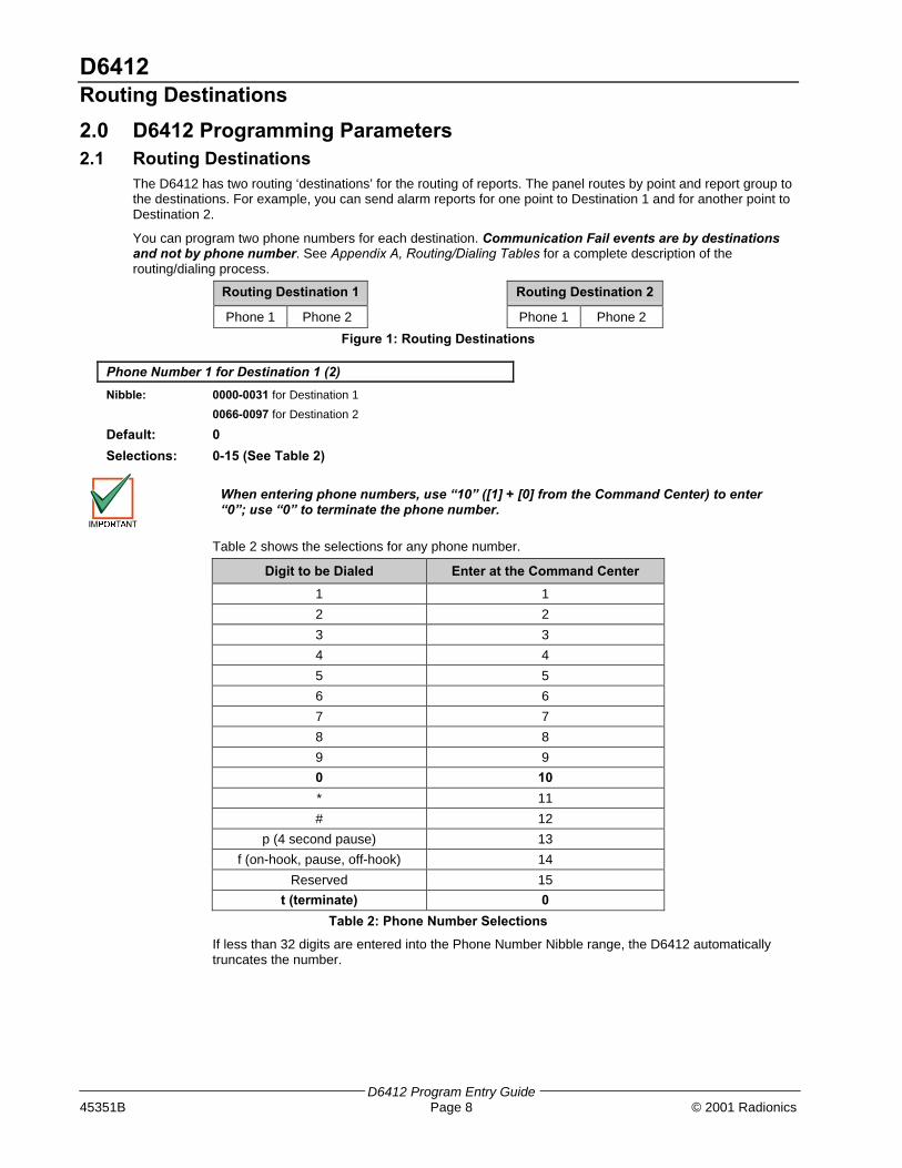
2.0 D6412 Programming Parameters2.1 Routing Destinations
The D6412 has two routing ‘destinations’ for the routing of reports. The panel routes by point and report group tothe destinations. For example, you can send alarm reports for one point to Destination 1 and for another point toDestination 2.
You can program two phone numbers for each destination. Communication Fail events are by destinationsand not by phone number. See Appendix A, Routing/Dialing Tables for a complete description of therouting/dialing process.
Routing Destination 1 Routing Destination 2
Phone 1 Phone 2 Phone 1 Phone 2
Figure 1: Routing Destinations
Phone Number 1 for Destination 1 (2)
Nibble: 0000-0031 for Destination 1
0066-0097 for Destination 2
Default: 0
Selections: 0-15 (See Table 2)
When entering phone numbers, use “10” ([1] + [0] from the Command Center) to enter“0”; use “0” to terminate the phone number.
Table 2 shows the selections for any phone number.
Digit to be Dialed Enter at the Command Center
1 1
2 2
3 3
4 4
5 5
6 6
7 7
8 8
9 9
0 10
* 11
# 12
p (4 second pause) 13
f (on-hook, pause, off-hook) 14
Reserved 15
t (terminate) 0
Table 2: Phone Number Selections
If less than 32 digits are entered into the Phone Number Nibble range, the D6412 automaticallytruncates the number.

D6412Routing Destinations
D6412 Program Entry Guide© 2001 Radionics Page 9 45351B
2.1.1 Entering Phone Numbers from the Command Center
The panel can dial up to 32 digits per phone number. Each digit occupies one Nibble.
Note that to program a zero (0) when entering phone numbers from a Command Center,you must enter 10 at the programming Nibble for that digit.
Terminate telephone numbers with less than 32 digits by entering a zero (0) in theprogramming Nibble after the last digit to be dialed.
If you program Phone Number 1 with a sequence to cancel call waiting (typically *70pause) followed by the phone number, you should program Phone 2 without the callwaiting cancel sequence. If the subscriber cancels Call Waiting without notifying theiralarm installing company the panel will still be able to send reports using Phone 2.Dialing a call waiting sequence on a non-call waiting line prevents the system fromdialing the central station receiver successfully.
2.1.2 Alternate Communication Path
The D6412 can send reports using alternate communication paths (other than phone). To use an alternatecommunication path:
1. Connect and configure the appropriate alternate communication module. See the installation manualprovided with the module for installation instructions.
2. Enter the Terminate selection (0) as the first digit of the Phone Number for the alternate communicationmodule.
3. Follow the zero (0) with the number for an alternate communication path as shown in Table 3.
4. Alternate Communication modules generate the following reports: AltComm Cond [166], AltComm Fail[167], AltComm Rstrl [16]. See Appendix B: Panel Events and Reporting Formats for a description of eachreport.
Alternate Communication Path Number to Enter after Termination Zero (0)
Alternate Communication Paths will bedefined in a later revision
TBD
Table 3: Alternate Communication Selections
Phone Number 2 for Destination 1 (2)
Nibble: 0032-0063 for Destination 1
0098-0129 for Destination 2
Default: 0
Selections: 0-15 (See Table 2)
When entering phone numbers, use “10” ([1] + [0] from the Command Center) to enter“0”; use “0” to terminate the phone number.
See Phone Number 1 for Destination 1 (2) for programming information.

D6412Routing Destinations
D6412 Program Entry Guide45351B Page 10 © 2001 Radionics
Format for Destination 1 (2)
Nibble: 0064 for Destination 1
0130 for Destination 2
Default: 1 = Modem IIIa²
Selections: 1 = Modem IIIa²
2 = Contact ID
3 = Reserved
4 = Basic Pager
Use this parameter to select a reporting format. All reports for this destination will be sent in theformat chosen here.
Leave this parameter at the default setting to transmit reports in the Radionics Modem IIIa² formatwith its advanced reporting capabilities.
Only the following Central Station Receivers support the D6412 Modem Format:
− D6600 with CPU v.01.01.03 (or higher)
− D6500 with D6511 MPU v1.05 (or higher)
The D6500 with D6510 MPU does not support the D6412 Modem Format.
See Appendix B: Panel Events and Reporting Formats for a complete description of each reportingformat and a listing of the specific D6412 reports.
Check panel communications (from panel to Central Station) to verify that the panel iscommunicating properly in the selected reporting format at least once annually.
Reserved
Nibble: 0065, 0131

D6412Phone, Auto-Forward and RAM Configuration
D6412 Program Entry Guide© 2001 Radionics Page 11 45351B
2.2 Phone, Auto-Forward and RAM ConfigurationUse the parameters in this section to set the dialing format for the D6412 and to configure the Auto-Forward and RAM (Remote Account Manager) features.
DTMF/Pulse Dialing
Nibble: 0132
Default: 0 (DTMF)
Selections: 0 = DTMF1 = Pulse
The D6412 dials in the format selected here (DTMF or Pulse). This format is used for all dialingattempts.
Call Forwarding Auto On Digits
Nibble: 0133-0164
Default: 0
Selections: 0-15 (See Table 2)
This parameter configures the D6412’s Call Forwarding Auto On/Off feature.
In order to use this feature, the premises must have Call Forwarding service from the localtelephone company. The D6412 Call Forwarding Auto On/Off feature does not forwardcalls; it turns the telephone company’s Call Forwarding service on or off by dialing digitsjust as the user would.
If the D6412’s Call Forwarding Auto On/Off feature is enabled and a user turns the system All On,the panel dials the digits and characters entered at this parameter to activate the telephonecompany’s Call Forwarding service.
A typical dialing sequence might be:
• two-digit telephone company feature code (72)
• pause
• phone number to forward to (315-555-1212)
• flash (on-hook, pause, off-hook)
• terminate (t)
For this sequence, the entry at this parameter would be:7 2 p 3 1 5 5 5 5 1 2 1 2 f t.
The Auto-Forward feature is only available for Area 1.
When entering phone numbers, use “10” ([1] + [0] from the Command Center) to enter“0”; use “0” to terminate the phone number.

D6412Phone, Auto-Forward and RAM Configuration
D6412 Program Entry Guide45351B Page 12 © 2001 Radionics
Call Forwarding Auto Off Digits
Nibble: 165-0180
Default: 0
Selections: 0-15 (See Table 2)
This parameter configures the D6412’s Call Forwarding Auto On/Off feature.
In order to use this feature, the premises must have Call Forwarding service from the localtelephone company. The D6412 Call Forwarding Auto On/Off feature does not forwardcalls; it turns the telephone company’s Call Forwarding service on or off by dialing digitsjust as the user would.
The D6412 dials the digits entered here (up to 16) when the Call Forwarding Auto On/Off feature isenabled and the system is turned Off (from All On).
If the D6412’s Call Forwarding Auto On/Off feature is enabled and a user turns the system off (fromAll On), then the panel dials the digits and characters entered at this parameter to turn off the CallForwarding service.
When entering phone numbers, use “10” ([1] + [0] from the Command Center) to enter“0”; use “0” to terminate the phone number.
The Auto-Forward feature is only available for Area 1.
Remote Programming Call Back Phone Number
Nibble: 0181-0212
Default: 0
Selections: 0-15 (See Table 2)
The phone number you enter here is the number the D6412 dials to initiate RAM IV remoteprogramming sessions. A session can be started by:
• RAM IV calls the panel, the panel answers and determines it is RAM calling, then the panelhangs up and calls RAM back
• If a RAM Call Back phone number is entered, Cmd 43 can be used to initiate a panel call to RAMIV.
• If a RAM Call Back phone number is not entered, the panel must receive an incoming call beforeusing Cmd 43.
The panel can be programmed to call this number automatically at test report time (see AutomaticTest Report Options, page 23, for more information).
When entering phone numbers, use “10” ([1] + [0] from the Command Center) to enter “0”; use “0”to terminate the phone number.

D6412Phone, Auto-Forward and RAM Configuration
D6412 Program Entry Guide© 2001 Radionics Page 13 45351B
RAM Answer Ring Count, Answering Machine Bypass
Nibble: 0213
Default: 7
Selections: 0 = Panel will not answer the phone1 - 13 = Ring Count14 = Answering Machine Bypass 115 = Answering Machine Bypass 2
The ring count sets the number of rings the panel waits for before picking up and seizing the phoneline for a remote programming session, or for remote arming with a telephone (see Arming Options1, page 27).
The panel will not seize the phone line for remote programming or remote arming with telephonewhen this parameter is set to zero (0).
This ring count is used for any panel arming state, armed or disarmed.
The Answering Machine Bypass function can be restricted to only operate when All or Part On (seeArming Options 1, page 27). When the Answering Machine Bypass function is restricted to onlyoperate when the system is All or Part On, the panel will not answer the phone for a remote armingsession when it is disarmed (Off). However, Cmd 43 – Remote Program, can still initiate a remoteprogramming session. See Appendix D: Operations Guide for a description of all commandfunctions available to the D621 LED Command Center and D623/D625 Text Command Centers.
Answering Machine Bypass 1
1. Call the premises; let the phone ring no more than two (2) times. Then hang up/disconnect theremote programmer.
2. Wait at least eight (8) seconds to call back, but call back within 45 seconds.
3. The panel will then pick up after the first ring.
Answering Machine Bypass 2
1. Call the premises; let the phone ring no more than four (4) times. Then hang up/disconnect theremote programmer.
2. Wait at least eight (8) seconds to call back, but call back within 45 seconds.
3. The panel will then pick up after the first ring.
RAM Passcode
Nibble: 0214-0219
Default: 9,9,9,9,9,9
Selections: 0 – 9, A-F (10 = A to 15 = F)
Six (6) characters are required. The RAM Passcode in the remote programmer must match theRAM Passcode in the panel in order to make a successful connection.

D6412Phone, Auto-Forward and RAM Configuration
D6412 Program Entry Guide45351B Page 14 © 2001 Radionics
Phone Line Fault Response Options
Nibble: 0220
Default: 0
Selections: 0, 1, 3, 5-7 (See Table 4)
Enter This Value to Select Options
Phone Line Fault Option 0 1 2 3 4 5 6 7 8 9 10 11 12 13 14 15
No Phone Line Supervision X
Trouble at Command Center X X X X
Burg Alarm & Strobe Functions, All or Part On X X X
Burg Alarm & Strobe Functions, Off X X X
Table 4: Phone Line Fault Options
The D6412 monitors the phone line for voltage only. The voltage on the line must drop below 3Vand stay there for at least 40 seconds. The D6412 declares the line restored when the voltage risesabove 3V and stays there for at least 40 seconds.
When enabled, the Phone Line Fault event appears at all Command Centers for all areas. TheD6412 sends a Phone Line Restore [100] report when a phone line fault event restores.
If the phone line fails (as described above), but restores before a Comm Fail event:
1. System detects phone line fail and puts Event [99] in the log.2. System starts dialing attempts if programmed for Phone Fail report.3. Phone line restores before comm fail event.4. System sends phone line fail and phone line restore reports.
If the phone line fails (as described above), but does not restore:
1. System detects phone line fail and puts report in the event in the log.2. System starts dialing attempts if programmed for Phone Fail report.3. Dialing attempts end with comm fail event, phone fail report is flushed.4. System detects phone line is restored and puts restoral report in buffer.5. System starts dialing attempts and sends phone fail restoral and comm restoral reports.
If an alternate communication path is enabled, the D6412 can send a Phone Line Fail [99] reportvia the alternate communication path when a phone line fault event occurs.
• No Phone Line Supervision: If selected, the D6412 will not monitor the phone line voltage.Phone Line Fault events will not appear at command centers. The other Phone Line FaultResponse options are also disabled if No Phone Line Supervision is selected.
• Trouble at Command Center: If a phone line fault occurs as described above, the CommandCenter displays a phone line trouble message. To enable the Command Center to emit a troubletone on system troubles, see Command Center Options, page 46, for details.
• Burg Alarm & Strobe Functions, All or Part On: If a phone line fault occurs as describedabove, the system’s burglary alarm and strobe function as configured when the system is armedAll On or Part On. See page 73, Outputs, for burglary alarm/strobe output configuration.
• Burg Alarm & Strobe Functions, Off: If a phone line fault occurs as described above, thesystem’s burglary alarm and strobe function as configured when the system is off (not armed).See page 72, Outputs, for burglary alarm/strobe output configuration.
For UL Listed installations, phone line supervision must be turned on (enter 1 at Nibble0220.

D6412Global Reporting Options
D6412 Program Entry Guide© 2001 Radionics Page 15 45351B
2.3 Global Reporting OptionsThese parameters configure the reporting for all areas, all points and all users.
Global Reporting Options
Nibble: 0221
Default: 1 = Enable Reporting
Selections: 0, 1, 3, 5, 7, 9, 11, 13, 15 (See Table 5)
Enter This Value to Select Options
Global Reporting Option 0 1 2 3 4 5 6 7 8 9 10 11 12 13 14 15
Local Only X
Enable Reporting X X X X X X X X
Extend Handshake X X X X
Delay Alarm Output X X X X
Burg Alarm After Two Failed Attempts X X X X
Table 5: Global Reporting Options
• Local Only: the panel sends no reports.
• Enable Reporting: the panel will send reports as programmed provided that at least one phonenumber has been programmed for at least one Routing Destination (see Routing Destinations,page 8). Reporting options can be enabled and disabled in other parameters. See Open/CloseReporting Options, page 29; Area # Open/Close Reporting Options, page 34; Authority LevelOption 6, page 37; and Reporting Enable, Trouble Response Options, Point Index ##, page 64.
• Extend Handshake: when the panel finishes dialing the central station receiver it waits for a‘handshake’ tone from the receiver. The ‘handshake’ is the first thing the receiver sends afteranswering the phone. Typically each reporting format the receiver supports has its ownhandshake tone. If a receiver supports several formats it sounds the handshake tones one attime.Choosing this option extends the time the panel waits for a handshake from the central stationreceiver from 45 to 60 seconds.
Radionics recommends that you only extend the handshake wait when advised byRadionics Technical Support.
• Delay Alarm Output: the panel delays burglary alarm output until communication to the centralstation receiver is complete or there are two failed dialing attempts. The delayed alarm outputfunctions are 1-8, 1-9 and 1-10 (see page 74 for descriptions of output types). ‘Bell Time’ is notdelayed, and begins at the alarm event. If Bell Time is set at three minutes or less, alarm outputdelayed by this feature may be very short (less than 1 minute), or the alarm output may notactivate at all. See Outputs, page 73, for a complete description of output functions. Thecommand center sounder is not delayed by this option.
• Burg Alarm After Two Failed Attempts: Setting this option to Yes provides a steady alarmoutput after two failed attempts to transmit a burglary alarm report from any point when thesystem is armed. Alarm output is provided even if the point is not programmed for alarm output.Bell Time must be programmed with at least 3 minutes to use this option. Set this option to No ifyou want to prevent an alarm output from silent points even when the system fails tocommunicate with the receiver. This option only applies to output types 1,8 (Alarm – All On, PartOn & Part 2 On; non-fire 24-hr alarms); 1,9 (Alarm – Part & Part 2 Modes; non-fire 24-hr alarms)and 1,10 (Alarm – Controlled points, 24-hr points-fire & non-fire). See Outputs, 73, page foralarm configuration.
The burg alarm output will still activate after two failed communication attempts even ifit is set for silent operation.

D6412Global Reporting Options
D6412 Program Entry Guide45351B Page 16 © 2001 Radionics
Ack Wait Time
Nibble: 0222
Default: 5 (5 seconds)
Selections: 0 - 15 (1-15 seconds; 1-second increments, 0 = 1 second)
Use this parameter to set the amount of time the D6412 waits for an acknowledgment tone from thecentral station receiver.
Radionics strongly recommends that the default value be used unless otherwiseinstructed by Radionics Technical Support.
AC Power Supervision Options
Nibble: 0223
Default: 5
Selections: 0-15 (See Table 6)
Enter This Value to Select Options
AC Power Supervision Option 0 1 2 3 4 5 6 7 8 9 10 11 12 13 14 15
No Options Selected X
AC Fail Report is Tag-along X X X X X X X X
Disable AC Fail Local Annunciation (at Command Ctr) X X X X X X X X
Enable Arm/Disarm/Bypass Tracking X X X X X X X X
Enable Internal Crystal to Keep Time X X X X X X X X
Table 6: AC Power Supervision Options
Use this parameter to configure the D6412’s local response to AC power failure.
AC power must be failed for a minimum of two (2) minutes before the D6412 responds to thefailure. It must be restored for a minimum of two (2) minutes before the D6412 responds to the ACrestoral.
The trouble tone for AC fail events sounds at all command centers in all areas. Silencing thetrouble tone for a system status trouble silences the trouble at all command centers in all areas.
• AC Tag-along: AC Fail and Restoral reports are not sent at the time of the event, but are sent as‘tag-along’ reports with the next report to be sent.
• Disable AC Fail Local Annunciation (at Command Center): If the control is only powered froma DC power source (through battery connections), select Option 2, Disable AC Fail AC Fail LocalAnnunciation. This will prevent the panel from annunciating AC failures locally at the commandcenter. You must also disable AC Fail reporting at the next parameter, AC Fail, Low BatteryReport Options.
• Enable Arm/Disarm/Bypass Tracking: If Option 4, Enable Arm/Disarm/Bypass Tracking, is notselected, the panel always powers up in the disarmed state (Off), even if the panel was armedbefore powering down. Points that were bypassed before powering down are not bypassed atpower-up.
• Enable Internal Crystal to Keep Time: Not selecting this option keeps time by looking at the 60Hz in AC power. Enable if running on DC only (for example, if you are generating your ownpower or power cycles are not consistent), otherwise leave set to default.

D6412Global Reporting Options
D6412 Program Entry Guide© 2001 Radionics Page 17 45351B
AC Fail [1], Low Battery [22] Report Options
Nibble: 0224
Default: 4
Selections: 0-15 (See Table 7)
Enter This Value to Select Options
AC Fail, Low Battery Reporting Options 0 1 2 3 4 5 6 7 8 9 10 11 12 13 14 15
No AC Fail Reports, No Low Battery Reports X
AC Fail Reports X X X X X X X X
AC Restoral Reports X X X X X X X X
Low & Missing Battery and Restoral Reports X X X X X X X X
Ground Fault and Restoral Reports X X X X X X X X
Table 7: AC Fail Report and Low Battery Report Options
AC Fail, Low Battery and Ground Fault events occur at all Command Centers for all areas.
Use this parameter to enable reporting of AC power and battery supervision events, and groundfault events. You must also program at least one phone number for at least one RoutingDestination (see page 8), and enable reporting at the Global Reporting Options parameter (seepage 15).
The battery is considered low if the nominal voltage on the battery terminals drops below 12.1 volts.
If the nominal voltage on the battery terminals drops below 10.2 volts, the low battery will beconsidered a missing battery.
System Status Report Swinger Count
Nibble: 0225
Default: 0
Selections: 0-15
Set this parameter to zero (0) to disable the System Status Report Swinger feature. System Statusreports are sent as they occur.
Entering a value from 1 to 15 enables the System Status Report Swinger feature and sets theswinger count. Each system status report has its own swinger counter. When the count is reachedthat report is no longer transmitted during the arming cycle.
For example, if you entered 1 at this parameter, the panel would only transmit one AC fail report,no matter how many times AC failed and restored during the arming cycle.
Not all System Status Reports follow this Swinger Count. System Status reports that follow thecount set in this parameter are marked with an ‘S’ in Reporting Formats Table found in Appendix B.
System Status Reports Routing
Nibble: 0226
Default: 1
Selections: 0 = No Reports, no Events to Log/Printer1 = Reports to Destination 1, Events to Log/Printer2 = Reports to Destination 2, Events to Log/Printer3 = Reports to Destinations 1 & 2, Events to Log/Printer4 = Reports to Destination 2 only on Destination 1 Comm Fail Event, Events to Log/Printer5 = No reports, Events to Log/Printer
System Status reports routed by this parameter are marked with an “R” in Appendix B: ReportingFormats.
Comm Fail 1 (2) reports follow System Status Reports routing. Comm Fail reports for eitherdestination are only sent if the other destination is the System Status Reports destination. SeeAppendix A for the dialing sequence and description of the Comm Fail event.

D6412Global Reporting Options
D6412 Program Entry Guide45351B Page 18 © 2001 Radionics
Call for Service Interval
Nibble: 0227-0228
Default: 0,0
Selections: 0 - 9
Use this parameter to determine the interval in weeks (7 days), (00 to 99). For example, if you enter0,2, the panel waits 2 weeks (14 days) between displaying service messages.
At this interval, the Command Center displays a Call for Service fault and/or sends a Call forService [37] report (per the Call for Service/System Inactive Options parameter below). The displayappears at all command centers in all areas. The report is sent for Area 1 only and follows SystemStatus Report routing.
Cmd 47 (Reset Sensors) resets the fault at all the command centers in all areas.
System Inactive Interval
Nibble: 0229-0230
Default: 0,0
Selections: 0 - 9
If an area is not armed (All, Part, or Part 2) in this interval, the panel sends a System Inactive [136]Report for that area. A ‘System Inactive’ Display is optional, see the Call for Service/SystemInactive parameter below. Interval is in weeks (00 to 99).
Call for Service/System Inactive Options
Nibble: 0231
Default: 8
Selections: 0-15 (See Table 8)
Enter This Value to Select Options
Call for Service/System Inactive Option 0 1 2 3 4 5 6 7 8 9 10 11 12 13 14 15
No Options X
Call for Service Display at Call for Service Interval X X X X X X X X
Call for Service Report at Call for Service Interval X X X X X X X X
Call for Service Display at System Inactive Interval X X X X X X X X
Enable Weekly Test Reminder X X X X X X X X
Table 8: Call for Service/System Inactive Options
• Call for Service Display at Call for Service Interval: At the Call for Service Interval, theCommand Center displays a ‘Call for Service’ trouble at all command centers in all areas and/orsends a report for Area 1. Cmd 47, Reset Sensors, resets the fault at all command centers in allareas. There is no trouble tone for the Call for Service Interval event.
• Call for Service Report at Call for Service Interval: The Call for Service [37] Report followsSystem Status routing. The interval is in weeks (00 to 99). See Call for Service Interval.
• Call for Service Display at System Inactive Interval: At the System Inactive Interval, theCommand Center displays a ‘Call for Service’ trouble at all command centers and/or sends aSystem Inactive [136] report for that area. See System Inactive Interval.
• Enable Weekly Test Reminder: if you select this option, the system command centers displaySystem Test Due, Press 1 to test. A reminder is generated eight (8) days after the lastuser test. There is no trouble tone for this trouble reminder event. When the user entersCmd 4 to view the trouble, the system displays System Test Due, Press 1 to test.

D6412Global Reporting Options
D6412 Program Entry Guide© 2001 Radionics Page 19 45351B
Log Supervision Configuration
Nibble: 0232
Default: 2
Selections: 0 = No Log Threshold Events or Reports, No Log Overflow Events or Reports1 = Overflow Event and Report [84]; Threshold Event and Report [85] at 50% full2 = Overflow Event and Report [84]; Threshold Event and Report [85] at 75% full3 = Overflow Event and Report [84]; Threshold Event and Report [85] at 90% full4 = Overflow Event; Threshold Event at 50% full; Local Events, No Reports5 = Overflow Event; Threshold Event at 75% full; Local Events, No Reports6 = Overflow Event; Threshold Event at 90% full; Local Events, No Reports
The D6412 can store up to 254 events in its event log (history). On startup, a new panel has 100%of its log available for new events. It is 0% full. As the panel begins storing events the capacity fornew events is reduced. When event 254 is stored the panel is 100% full. On the 255th event thepanel begins overwriting events (beginning with the oldest).
The RAM IV remote programmer can access the panel log. Once the log is received by RAM IV,events can be ‘cleared’, returning the log to 0% capacity.
To help avoid overwriting events that have not been received by RAM IV, this parameter configuresthe system for supervision of its event log (history).
Setting this parameter to 0 disables supervision. No log threshold or overflow events are entered inthe log. No log reports are sent.
Setting this parameter to 1, 2, or 3 creates log overflow and threshold events in the log. A thresholdevent is created when the panel writes the first event to the log that exceeds the threshold (50%,75%, or 90% full). A threshold report reminds the central station to access the event log with RAMIV, freeing log space, before the panel reaches 100% full (log overflow) and begins overwritingevents.
Overflow events are created when the log reaches 100% of capacity and begins writing over eventsthat have not been received by RAM IV.
Setting this parameter to 4, 5, or 6 creates the threshold and overflow events, but no reports aresent. The events are local only.
Log events (threshold and overflow) only ever appear in the log. They are not system troubles.They are viewed locally with Cmd 85 – View Log, or remotely with RAM IV.
Auto On Pre-Alert Time
Nibble: 0233
Default: 6 (30 minutes)
Selections: 0 – 15 (time = selection x 5 minutes)
Multiply the value entered in this parameter by five (5) minutes to determine the duration of theAuto On Pre-Alert. The pre-alert sounds before the Auto On Sked to warn users to exit or extend(Cmd 51) the auto arming. See Authority Level Option 12, page 39, to configure the AuthorityLevels for Cmd 51.
At the Auto On time, the panel starts exit delay. See Skeds, page 79, for a complete description ofthe Auto On Skeds.
If the area is armed according to the scheduled arming state (All On or Part On) during Auto OnPre-Alert Time and then disarmed before the scheduled arming, auto-arming will not occur.

D6412Global Reporting Options
D6412 Program Entry Guide45351B Page 20 © 2001 Radionics
Cancel Event Enabled
Nibble: 0234
Default: 1
Selections: 0 = No Cancel Reports1 = Cancel Reports Enabled
If the Cancel Event is enabled (enter 1 in at Nibble 0234), a ‘Cancel Window’ starts with theinitiation of alarm events. The Cancel Window is equal to Bell Time. If the user acknowledges thealarm inside the cancel window, a Cancel Event is created. If reporting is enabled, a Cancel [38] orFire Cancel [39] report is sent.
If the Abort feature is enabled, the Cancel report is sent if the user acknowledges the alarm afterthe Abort Window has expired but before the Cancel Window expires. See Alarm Event AbortWindow, page 69, for more information.
If a user acknowledges a non-fire alarm event by entering their passcode before the Alarm EventAbort Window expires:
1. The alarm event is aborted. Alarm, Cancel* and Restoral reports associated with the alarm arenot transmitted. The alarm event becomes a local only event.
2. The user hears a unique three long beep tone at the command center.
3. The text command center indicates the aborted alarm on the display. The LED commandcenters indicate the aborted alarm with a slow flash in Alarm Memory.
* A Cancel Window starts with the initiation of the alarm event and follows Bell Time. If the useracknowledges the alarm inside the cancel window (bell time), a Cancel [38] or Fire Cancel [39]report is sent. If the Abort feature is enabled, the Cancel report is sent if the user acknowledgesthe alarm after the Abort Window has expired but before bell time expires.
Alarm Event Abort is required for SIA Control Panel Standard for False Alarm Reduction.
Reserved
Nibble: 0235-0243

D6412Tests
D6412 Program Entry Guide© 2001 Radionics Page 21 45351B
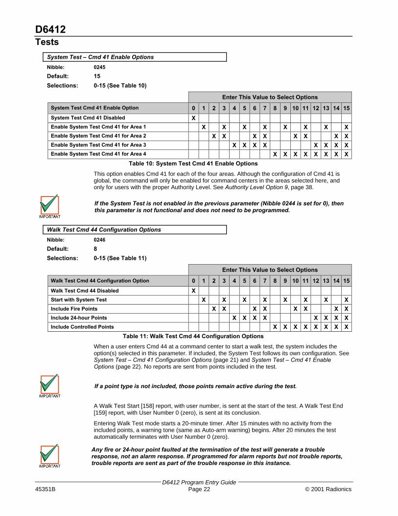
2.4 Tests
System Test – Cmd 41 Configuration Options
Nibble: 0244
Default: 5
Selections: 0-15 (See Table 9)
Enter This Value to Select Options
System Test Cmd 41 Configuration Options 0 1 2 3 4 5 6 7 8 9 10 11 12 13 14 15
System Test Cmd 41 Disabled X
Test Bell X X X X X X X XTest Strobe X X X X X X X X
Test Battery X X X X X X X X
Send Test Report X X X X X X X X
Table 9: System Test Cmd 41 Configuration Options
This is a global (all areas) option.
When the user enters Cmd 41 at the command center, the system performs a self-test that includesthe options selected at this parameter. The configuration applies to all areas.
For UL 1023, Household Fire Systems, you must select Test Bell, Test Strobe (if installed)and Test Battery (enter 7 for this parameter).
• Test Bell: makes a “bell test” part of the system test. The panel activates the Bell Time (1–5) andAlarm Output (1-8, 1-9, 1-10, 1-11, and 1-12) functions for three (3) seconds. See Outputs, page73, for a complete description of output functions.
• Test Strobe: makes a “strobe test” part of the system test. The panel activates the StrobeOutput functions and waits for the user to press the [∗] key to end the test. If the user fails topress the [∗] key within 20 minutes, the D6412 automatically terminates the strobe test andproceeds to the next programmed test.
• Test Battery: makes the “battery test” part of the system test. The battery test causes thesystem to run on battery power only for four (4) minutes. If the battery voltage falls below 12.1volts during the four-minute test, or if the battery is missing, the system restores AC power anddisplays a system trouble at all command centers. If programmed for battery reports, the panelsends a low battery or missing battery report. Users can end the test by pressing [Cmd] on thecommand center.
• Send Test Report: makes a “communications test” part of the system test. If selected, thisoption causes the panel to attempt to send a Test [137] report when the user initiates a SystemTest with Cmd 41. If there is a system trouble present at the time of the test, the panel sends aTest, Off Normal [138] report. The test report follows the routing for the Automatic Test [137]report. If the test communication is unsuccessful, the panel creates a system troublecommunication failure.
D6412Tests
D6412 Program Entry Guide45351B Page 22 © 2001 Radionics
System Test – Cmd 41 Enable Options
Nibble: 0245
Default: 15
Selections: 0-15 (See Table 10)
Enter This Value to Select Options
System Test Cmd 41 Enable Option 0 1 2 3 4 5 6 7 8 9 10 11 12 13 14 15
System Test Cmd 41 Disabled X
Enable System Test Cmd 41 for Area 1 X X X X X X X X
Enable System Test Cmd 41 for Area 2 X X X X X X X X
Enable System Test Cmd 41 for Area 3 X X X X X X X X
Enable System Test Cmd 41 for Area 4 X X X X X X X X
Table 10: System Test Cmd 41 Enable Options
This option enables Cmd 41 for each of the four areas. Although the configuration of Cmd 41 isglobal, the command will only be enabled for command centers in the areas selected here, andonly for users with the proper Authority Level. See Authority Level Option 9, page 38.
If the System Test is not enabled in the previous parameter (Nibble 0244 is set for 0), thenthis parameter is not functional and does not need to be programmed.
Walk Test Cmd 44 Configuration Options
Nibble: 0246
Default: 8
Selections: 0-15 (See Table 11)
Enter This Value to Select Options
Walk Test Cmd 44 Configuration Option 0 1 2 3 4 5 6 7 8 9 10 11 12 13 14 15
Walk Test Cmd 44 Disabled X
Start with System Test X X X X X X X X
Include Fire Points X X X X X X X X
Include 24-hour Points X X X X X X X X
Include Controlled Points X X X X X X X X
Table 11: Walk Test Cmd 44 Configuration Options
When a user enters Cmd 44 at a command center to start a walk test, the system includes theoption(s) selected in this parameter. If included, the System Test follows its own configuration. SeeSystem Test – Cmd 41 Configuration Options (page 21) and System Test – Cmd 41 EnableOptions (page 22). No reports are sent from points included in the test.
If a point type is not included, those points remain active during the test.
A Walk Test Start [158] report, with user number, is sent at the start of the test. A Walk Test End[159] report, with User Number 0 (zero), is sent at its conclusion.
Entering Walk Test mode starts a 20-minute timer. After 15 minutes with no activity from theincluded points, a warning tone (same as Auto-arm warning) begins. After 20 minutes the testautomatically terminates with User Number 0 (zero).
Any fire or 24-hour point faulted at the termination of the test will generate a troubleresponse, not an alarm response. If programmed for alarm reports but not trouble reports,trouble reports are sent as part of the trouble response in this instance.

D6412Tests
D6412 Program Entry Guide© 2001 Radionics Page 23 45351B
Walk Test Cmd 44 Enable Options
Nibble: 0247
Default: 15Selections: 0-15 (See Table 12)
Enter This Value to Select Options
Walk Test Cmd 44 Enable Option 0 1 2 3 4 5 6 7 8 9 10 11 12 13 14 15
Walk Test Cmd 44 Disabled X
Walk Test Cmd 44 Enabled for Area 1 X X X X X X X X
Walk Test Cmd 44 Enabled for Area 2 X X X X X X X X
Walk Test Cmd 44 Enabled for Area 3 X X X X X X X X
Walk Test Cmd 44 Enabled for Area 4 X X X X X X X X
Table 12: Walk Test Cmd 44 Enable Options
Use this parameter to choose which areas have Cmd 44 enabled. Although the configuration ofCmd 44 is global, the command will only be enabled for command centers in the areas selectedhere, and only for users with the proper Authority Level. See Authority Level Option 9, page 38.
Walk Test Start [158] / Walk Test End [159] Report Routing
Nibble: 0248
Default: 5Selections: 0 = No Reports, No Events to Log/Printer
1 = Reports to Destination 1; Events to Log/Printer2 = Reports to Destination 2; Events to Log/Printer3 = Reports to Destinations 1 & 2; Events to Log/Printer4 = Reports to Destination 2 Only on Destination 1 Comm Fail Event; Events to Log/Printer5 = No Reports; Events to Log/PrinterThis is a global (all areas) parameter. See Appendix A for the dialing sequence and a description ofa Comm Fail Event.
Automatic Test [137] Report Options
Nibble: 0249
Default: 0Selections: 0-15 (See Table 13)
Enter This Value to Select Options
Automatic Test Report Options 0 1 2 3 4 5 6 7 8 9 10 11 12 13 14 15
No Automatic Test Options X
Test Report Only If System Is Armed X X X X
Defer Test Report If Other Report Sent in Test Interval X X X X
Test Reports for All Areas (else Area 1 only) X X
Call RAM at Test Time (After Test Report) X X X X X
Table 13: Automatic Test [137] Report Options
Use these options to configure the Automatic Test [137] report. If Option 8 is selected, a variety oftasks could be accomplished at this time, including downloading the log to the central station.
• Test Report Only If System is Armed: this option sends a test report only if the system isarmed.
• Defer Test Report if Other Report Sent in Test Interval: if another report is sent during the testinterval, this option defers the test report until the end of the test interval.
• Test Reports for All Areas (else Area 1 only): if selected, this option generates a test report forall enabled areas.
• Call RAM at Test Time (After Test Report): if selected, this option calls RAM IV at test timeafter the system sends the test report. RAM IV Phone Number should be programmed. SeeRemote Programming Call Back Phone Number, page 12, for more information.

D6412Tests
D6412 Program Entry Guide45351B Page 24 © 2001 Radionics
Automatic Test Report [137] Time
Nibble: 0250-0253
Default: 0,0,0,0 (Test reports disabled)
Selections: 0 – 9
Enter the time of day for the Automatic Test. Use 24-hour format (HHMM) where midnight is 2400,noon is 1200 and 12:01 am is 0001. Enter one digit in each of the four Nibbles so that Nibbles 0250and 0251 are the hour and 0252 and 0253 are the minutes. An entry of 0000 (the default setting)disables the Automatic Test [137] report.
Automatic Test [137] Report Interval
Nibble: 0254
Default: 2
Selections: 0 = No Automatic Test1 = 1 Hour2 = 1 Day3 = 7 Days4 = 28 Days
Entering zero (0) at this parameter disables the Automatic Test [137] report feature.
The one-hour interval is incremented on the minute. For example, if you set the Automatic TestTime parameter to 1020 (10:20 am), the Automatic Test Interval is one hour, and left programmingmode at 11:10, then the panel would send a test report at 11:20 am (less than one hour afterleaving programming mode). The next test report would come at 12:20 pm.
The one-day, seven-day and 28-day intervals are incremented at midnight (2400). For example, ifyou set the Automatic Test Time parameter to 1020 (10:20 am), the Automatic Test Interval is oneday and left programming mode at 10:10 am, then the panel would not send a test report until10:20 the next day (after the one-day interval increment at midnight).
If the Automatic Test report is disabled in the previous parameter, this parameter becomesmeaningless for the Automatic Test, but is still useful when using RAM iV.
Test Report Routing
Nibble: 0255
Default: 1
Selections: 0 = No Reports; No Events to Log/Printer1 = Reports to Destination 1; Events to Log/Printer2 = Reports to Destination 2; Events to Log/Printer3 = Reports to Destination 1 & 2; Events to Log/Printer4 = Reports to Destination 2 Only on Destination 1 Comm Fail Event; Events to Log/Printer5 = No Reports; Events to Log/Printer
Test reports include the System Test [137] [138] reports from Cmd 41 and Cmd 44. The Walk TestStart [158] and Walk Test End [159] reports follow their own routing.
This is a global (all areas) parameter.
Reporting must be enabled at the Global Reporting Options prompt and at least one phonenumber must be entered for one routing destination.
D6412Programming Options
D6412 Program Entry Guide© 2001 Radionics Page 25 45351B
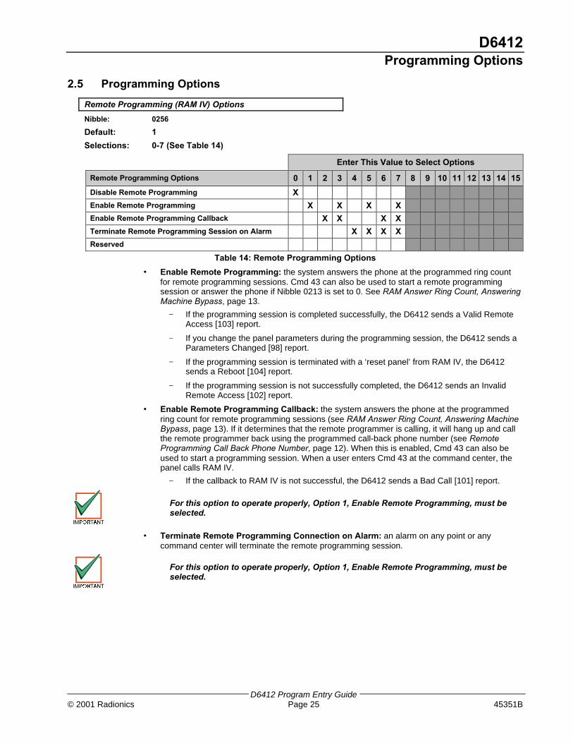
2.5 Programming Options
Remote Programming (RAM IV) Options
Nibble: 0256
Default: 1
Selections: 0-7 (See Table 14)
Enter This Value to Select Options
Remote Programming Options 0 1 2 3 4 5 6 7 8 9 10 11 12 13 14 15
Disable Remote Programming X
Enable Remote Programming X X X X
Enable Remote Programming Callback X X X X
Terminate Remote Programming Session on Alarm X X X X
Reserved
Table 14: Remote Programming Options
• Enable Remote Programming: the system answers the phone at the programmed ring countfor remote programming sessions. Cmd 43 can also be used to start a remote programmingsession or answer the phone if Nibble 0213 is set to 0. See RAM Answer Ring Count, AnsweringMachine Bypass, page 13.
− If the programming session is completed successfully, the D6412 sends a Valid RemoteAccess [103] report.
− If you change the panel parameters during the programming session, the D6412 sends aParameters Changed [98] report.
− If the programming session is terminated with a ‘reset panel’ from RAM IV, the D6412sends a Reboot [104] report.
− If the programming session is not successfully completed, the D6412 sends an InvalidRemote Access [102] report.
• Enable Remote Programming Callback: the system answers the phone at the programmedring count for remote programming sessions (see RAM Answer Ring Count, Answering MachineBypass, page 13). If it determines that the remote programmer is calling, it will hang up and callthe remote programmer back using the programmed call-back phone number (see RemoteProgramming Call Back Phone Number, page 12). When this is enabled, Cmd 43 can also beused to start a programming session. When a user enters Cmd 43 at the command center, thepanel calls RAM IV.
− If the callback to RAM IV is not successful, the D6412 sends a Bad Call [101] report.
For this option to operate properly, Option 1, Enable Remote Programming, must beselected.
• Terminate Remote Programming Connection on Alarm: an alarm on any point or anycommand center will terminate the remote programming session.
For this option to operate properly, Option 1, Enable Remote Programming, must beselected.

D6412Programming Options
D6412 Program Entry Guide45351B Page 26 © 2001 Radionics
Installer Switch and Daylight Savings Time Options
Nibble: 0257
Default: 15
Selections: 0-15 (See Table 15)
Enter This Value to Select Options
Installer Switch and Daylight Savings Time Options 0 1 2 3 4 5 6 7 8 9 10 11 12 13 14 15
No Options Selected X
Installer Switch Enabled X X X X X X X X
Auto Adjust for Daylight Savings Time Enabled X X X X X X X X
Keypad Programming Enabled X X X X X X X X
PK32 (Programming Key) Enabled X X X X X X X X
Table 15: Installer Jumper and Daylight Savings Time Options
• Installer Switch Enabled: the Installer Switch must be closed for local programming.
Radionics strongly recommends leaving the Installer Switch Enabled option in the default(enabled) configuration.
A closed Installer Switch disables most panel functions, including:
- panel reporting with alarms (only sends installer-initiated test reports and service startreports)
- the A, B and C keys- alarm output
A closed Installer Switch activates a Call for Service system trouble at all command centers.
The disabled reporting characteristic of the Installer Switch can be used for service tasks (forexample, replacing hold-up buttons). It could also be used to allow the panel’s battery to chargeduring the installation process.
• Auto Adjust for Daylight Savings Time Enabled: The D6412 automatically sets its clockahead one hour at 2:00 am on the first Sunday in April, and sets its clock back one hour at 2:00am on the last Sunday in October.
If Keypad Programming or PK32 are not enabled, access to the D6412 via a keypad willnot be possible. Remote programming (RAM IV) will be the only programming methodavailable.
• Keypad Programming Enabled: All panel parameters can be programmed from any systemtext keypad or an Installer Keypad. See page 130 for a description of the Installer Mode.
• PK32 (Programming Key) Enabled: The PK32 Programming Key can be used to send orreceive a program record (the panel’s parameter settings). See page 135 for more informationregarding the Programming Key.
If the Keypad Programming and Remote Programming options are not enabled, there willbe no way to access panel programming.

D6412Global Open/Close Options
D6412 Program Entry Guide© 2001 Radionics Page 27 45351B
2.6 Global Open/Close Options
Arming Options 1
Nibble: 0258
Default: 1
Selections: 0-7 (See Table 16)
Enter This Value to Select Options
Arming Options 0 1 2 3 4 5 6 7 8 9 10 11 12 13 14 15
No Options Enabled X
Enable All On – No Exit Feature X X X X
Answering Machine Bypass Only When All/Part On X X X X
Remote Arming with Telephone, Area 1 X X X X
Reserved
Table 16: Arming Options 1
• Enable All On – No Exit Feature: If this feature is selected and the system is turned All On andno entry or exit points are faulted during exit delay, the system automatically shifts to Part On(Part 1). Part On (not All On) appears in the log and reports.
Enable All On – No Exit is required for SIA Control Panel Standard for False AlarmReduction.
• Answering Machine Bypass Only When All/Part On: the Answering Machine Bypass functionis activated at the RAM Answer Ring Count, Answering Machine Bypass parameter (see page13). If activated there, this option can be used to restrict its function so that it only operates whenthe system is All On or Part On. The system will not answer if disarmed.
• Remote Arming with Telephone, Area 1: controls the built-in telephone arming feature for Area1. When enabled, the panel answers the phone on the ring count for remote programming.When the panel answers the phone:
− If the panel is All or Part On, it sounds three beeps and starts the handshake tone forremote programming.
− If the panel is Off, it sounds one short beep and then starts the handshake tone for remoteprogramming (one long beep). Press and hold the [5] key* for two seconds immediatelyafter the first short arming beep and before the handshake tone begins.
− The panel will arm if it detects a [5] key press from the telephone (All On with Delay,faulted points are force-armed like keyswitch arming). The panel waits three seconds,sounds three beeps (new armed state) and then hangs up.
− * If arming from a cell phone, quickly press the [5] key three times. If pressing and holdingthe [5] key for two seconds from a house (landline) phone does not produce a tone longenough to arm Area 1, retry by quickly pressing the [5] key three times.
Remotely disarming the panel cannot be done with a telephone.

D6412Global Open/Close Options
D6412 Program Entry Guide45351B Page 28 © 2001 Radionics
Arming Options 2
Nibble: 0259
Default: 0
Selections: 0-15 (See Table 17)
Enter This Value to Select Options
Arming Options 0 1 2 3 4 5 6 7 8 9 10 11 12 13 14 15
No Options Enabled X
First Area to Open / Last Area to Close Reporting X X X X X X X X
Make Area 1 Common Area X X X X X X X X
Enable Cmd 80 All Areas All On X X X X X X X X
Enable Cmd 81 All Areas Off X X X X X X X X
Table 17: Arming Options 2
• First Area to Open [164] / Last Area to Close [165] Reporting: The system transmits oneClosing [165] report when all areas are turned On and one Opening [164] report when any areais turned Off. Passcode and Opening/Closing reports must be enabled for all areas. Open andClose reports are for Area 1 using Area 1’s account numbers.
All area account numbers must be the same in order to send Area 1’s AccountNumbers. See Areas on page 33 for information on programming account numbers.
• Make Area 1 Common Area: All other areas are made common to Area 1. Area 1 arms when allthe other areas are armed All On, and Area 1 disarms when any other area is disarmed.
• Enable Cmd 80 All Areas All On*: Faulted points are force-armed. See Authority Level Option8, page 38, to configure the Authority Level for Cmd 80.
• Enable Cmd 81 All Areas Off*: Cmd 81 always requires a passcode. See Authority LevelOption 8, page 38, to configure the Authority Levels for Cmd 81.
* All = All areas in which the user has the appropriate authority level.
Bypass/Force-Arm Limit
Nibble: 0260
Default: 0
Selections: 0-15
The parameter configures all areas.
This parameter sets the maximum number of points that can be force-armed or bypassed for anyone area. The area will not arm if this limit is reached and points remain faulted.
Entering zero (0), the default setting, for this parameter allows an unlimited number of points to beforce-armed or bypassed. The Point Index determines which points are bypassable.
Force-arming is not permitted in UL installations.

D6412Global Open/Close Options
D6412 Program Entry Guide© 2001 Radionics Page 29 45351B
Open/Close Reporting Options
Nibble: 0261
Default: 15
Selections: 0-15 (See Table 18)
Enter This Value to Select Options
Open/Close Reporting Options 0 1 2 3 4 5 6 7 8 9 10 11 12 13 14 15
No Open, Close, Exit Error or Recent Close Reports X
Opening [89 – 96, 164] Reports Enabled X X X X X X X X
Closing [42 - 67, 165] Reports Enabled X X X X X X X X
Exit Error [18] Report Enabled X X X X X X X X
Recent Closing [19 – 20] Reports Enabled X X X X X X X X
Table 18: Open/Close Reporting Options
This is a global parameter that affects all points, all areas and all passcodes.
Once enabled and configured here, Opening and Closing reports can be restricted byarea (see Area Open/Close Reporting Option, page 34) and by Authority Level (seeAuthority Level Option 6, page 37). Reporting must be enabled at the system level first(see Global Reporting Options, page 15).
• Opening Reports Enabled: if selected, this option enables Opening [89-96, 164] reports.
• Closing Reports Enabled: if selected, this option enables Closing [42-67, 165] reports.
• Exit Error: Only the Exit Error [18] report is enabled and disabled by this parameter. The ExitError event is always enabled. If an entry or exit point (Point Types 11 and 12) is violated at theend of exit delay. These events will occur in this order:
1. Local alarm annunciation is started (command centers and alarm outputs)
2. Entry delay starts (the command center can either sound an alarm or initiate entry delay)
3. The alarm transmission procedure begins if the system is not turned off at the end of entrydelay. An Exit Error [18] report is included if programmed. The Exit Error report follows theAlarm Report routing.
Exit Error is required for SIA Control Panel Standard for False Alarm Reduction.
• Recent Closing: an Alarm Recent Closing [19 – 20] report (including the user number) is sentfor any alarm within two (2) minutes of the end of the exit time.
Recent Closing is required for SIA Control Panel Standard for False Alarm Reduction.

D6412Global Open/Close Options
D6412 Program Entry Guide45351B Page 30 © 2001 Radionics
Opening/Closing Report Routing
Nibble: 0262
Default: 1
Selections: 0 = No Reports; No Events to Log/Printer1 = Reports to Destination 1; Events to Log/Printer2 = Reports to Destination 2; Events to Log/Printer3 = Reports to Destination 1 & 2; Events to Log/Printer4 = Reports to Destination 2 Only on Destination 1 Comm Fail Event; Events to Log/Printer5 = No Reports; Events to Log/Printer
This is a global parameter that affects all points, all areas and all passcodes.
The Exit Error [18] and Recent Closing [19 – 20] reports follow alarm routing. See Appendix A forthe dialing sequence and a description of a Comm Fail event.
You must enable reporting at the Global Reporting Options prompt and enter at least onephone number for one routing destination.
Exit Time Restart
Nibble: 0263
Default: 1
Selections: 0 = No Exit Time Restart1 = Restart
If this parameter is set to Restart (1), a violation, restoral, second violation of an entry/exit point(before the end of exit delay) restarts exit delay. One restart is allowed per arming cycle. Violation,restoral, second violation must all occur at the same point.
Exit Time Restart is required for SIA Control Panel Standard for False Alarm Reduction.

D6412Global Open/Close Options
D6412 Program Entry Guide© 2001 Radionics Page 31 45351B
Entry Delay Time 1
Nibble: 0264-0265
Default: 1,14 (30 seconds)
Selections: 0,0 to 15,15
The shortest possible Entry Delay is 30 seconds, regardless of the values entered in thisparameter.
Entry Delay is the time the system allows the user to turn the system off before an alarm initiates.
If the user fails to turn off the system before entry delay expires, an alarm event occurs. Users mustenter through a point programmed for entry delay to start the entry delay timer.
The D6412 provides two entry delays. Only point types programmed to initiate Entry Delay 1 usethe entry delay time you set at the Entry Delay Time 1 parameter. Point types programmed toinitiate Entry Delay 2 use the entry delay time you set at the Entry Delay Time 2 parameter.
If the system is On and a user enters through a point assigned to Entry Delay 2, the systeminitiates Entry Delay 2. If the user enters through a point assigned to Entry Delay 1, and thenthrough a point assigned to Entry Delay 2, the system will not switch from Entry Delay 1 to EntryDelay 2.
The system sounds an entry delay tone at the area’s command center during entry delay.
Programming from the Command Center
Programming two Nibbles for each sets the Entry Delay Time 1 and Entry Delay Time 2parameters. The system multiplies the first entry in the first Nibble by 16 and adds it to the entry inthe second Nibble. For example, to set Entry Delay Time 1 to 50 seconds you would enter 3 in thefirst Nibble (3 x 16 = 48) and then enter 2 in the second Nibble (48 + 2 = 50). Use the formulabelow to calculate the delay time for programming this parameter.
3 16 48 + 2 = 50
(Nibble 0264)
x =
(Nibble 0265) (Entry Delay Time)
Entry Delay Time 2
Nibble: 0266-0267
Default: 7,8 (120 seconds)
Selections: 0,0 to 15,15 (range: 30 to 255 seconds)
See the previous parameter, Entry Delay Time 1, for information on programming Entry Delay Time2.
D6412Global Open/Close Options
D6412 Program Entry Guide45351B Page 32 © 2001 Radionics
Part Mode Delay Time
Nibble: 0268-0269
Default: 0, 0 (Disabled)
Selections: 0,0 to 15,15 (range: 30 to 255 seconds)
The lowest value that can be entered for Part Mode Delay is 30 seconds, regardless of thevalues entered in this parameter.
Making an entry in the Part Mode Delay Time parameter creates an entry delay time that onlyapplies when the system is Part On.If the system is Part On and any armed point is faulted (fire and 24-hour points excluded), thesystem starts a Part Mode entry delay timer. It uses this Part Mode timer for points that areassigned to either Entry Delay 1 or Entry Delay 2, and points that are not assigned entry delay.Setting the Part Mode Delay Time to zero disables the Part Mode delay feature. When Part On, thearmed points follow the entry delay assigned to them.
Programming from the Command Center
Programming two Nibbles sets the Part Mode Delay Time. The system multiplies the numberentered in the first Nibble by 16 and adds that total with the number entered in the second Nibble.For example, to set Part Mode Delay Time 1 to 50 seconds, you would enter 3 in the first Nibble (3x 16 = 48) and then enter 2 for the second Nibble (48 + 2 = 50). Use the formula below to calculatethe delay time for programming this parameter.
3 16 48 + 2 = 50(Nibble 0268)
x =(Nibble 0269) (Entry Delay Time)
Exit Delay Time 1
Nibble: 0270-0271
Default: 3,12 (60 seconds – UL Listed default)
Selections: 0,0 to 15,15 (range: 45 to 255 seconds)
The lowest value that can be entered for Exit Delay is 45 seconds, regardless of the valuesentered in this parameter.
Exit delay is the time the system allows users to exit the premises. Users must leave the premisesbefore exit delay expires.The D6412 provides two exit delays. When a user turns the system All or Part On with delay, thesystem always starts Exit Delay 1. Exit delay is set to the time you enter at the Exit Delay Time 1parameter.If a point assigned to Exit Delay 2 is faulted when exit delay is running, the system switches fromExit Delay 1 to Exit Delay 2 (the time you enter at the Exit Delay Time 2 parameter).If a user force-arms an Exit Delay 2 point, the system uses Exit Delay 2 and Entry Delay 2.
Programming from the Command Center
Programming two Nibbles for each parameter sets Exit Delay Time 1 and Exit Delay Time 2. Thesystem multiplies the number entered in the first Nibble by 16 and adds that total with the numberentered in the second Nibble. For example, to set Exit Delay Time 1 for 50 seconds, you wouldenter 3 in the first Nibble (3 x 16 = 48) and then enter 2 for the second Nibble (48 + 2 = 50).
Exit Delay Time 2
Nibble: 0272-0273
Default: 7, 8 (120 seconds)
Selections: 0,0 to 15,15 (range: 45 to 255 seconds)
See the previous parameter, Exit Delay Time 1, page 32, for information on programming ExitDelay Time 2.
Reserved
Nibble: 0274-0275

D6412Areas
D6412 Program Entry Guide© 2001 Radionics Page 33 45351B
2.7 AreasUse the parameters in this section to configure up to four Areas. Along with the parameters in this section, eachArea has 16 characters of programmable text for an Area name and 16 characters of programmable Area Idletext. All panel text is programmed from the command center in a special text-programming mode. SeeProgramming Text Nibbles on page 131 for text programming instructions.
AreaAccount # for Routing
Destination 1Account # for Routing
Destination 2Open/Close
Reporting OptionsLock AreaReporting
1 Nibble 0276-028510,10,10,10,0,0,0,0,0,0
Nibble 0286-029510,10,10,10,0,0,0,0,0,0
Nibble 02961
Nibble 02970
2 Nibble 0298-030710,10,10,10,0,0,0,0,0,0
Nibble 0308-031710,10,10,10,0,0,0,0,0,0
Nibble 03181
Nibble 03190
3 Nibble 0320-032910,10,10,10,0,0,0,0,0,0
Nibble 0330-033910,10,10,10,0,0,0,0,0,0
Nibble 03401
Nibble 03410
4 Nibble 0342-035110,10,10,10,0,0,0,0,0,0
Nibble 0352-036110,10,10,10,0,0,0,0,0,0
Nibble 03621
Nibble 03630
Table 19: Area Configuration Nibbles and Default Values
Area # Account Number for Routing Destination 1
Nibble: See Table 19
Default: See Table 19
Selections: 0-15 (See Table 20)
Each Area uses the account number entered in its account number in its reports to the centralstation receiver. Different account numbers can be programmed for two routing destinations. SeeRouting Destinations, page 8, for a complete description of how the D6412 routes reports to therouting destinations.
Account numbers can contain four, six, eight or ten digits. If less than four digits are entered, theD6412 adds up to four zeros to make a four-digit account number. If five, seven or nine digits areentered, the D6412 adds a zero to make the account number six, eight or ten digits in lengthrespectively.
Only Radionics’ Modem IIIa² format supports ten-digit account numbers. Verify that thecentral station receiver to which the D6412 reports supports Modem IIIa² and ten-digitaccount numbers before programming a ten-digit number in the Account Numbersparameters.
If you select a reporting format other than Modem IIIa², the panel will automatically truncate theaccount number to the maximum length supported by that format. See Appendix B for a completedescription of the reporting formats available in the D6412.
For This Selection Press This at the Cmd Ctr For This Selection Press This at the Cmd Ctr
0 10 8 8
1 1 9 9
2 2 B 11
3 3 C 12
4 4 D 13
5 5 E 14
6 6 F 15
7 7 Terminate 0
Table 20: Account Number Digit Selections
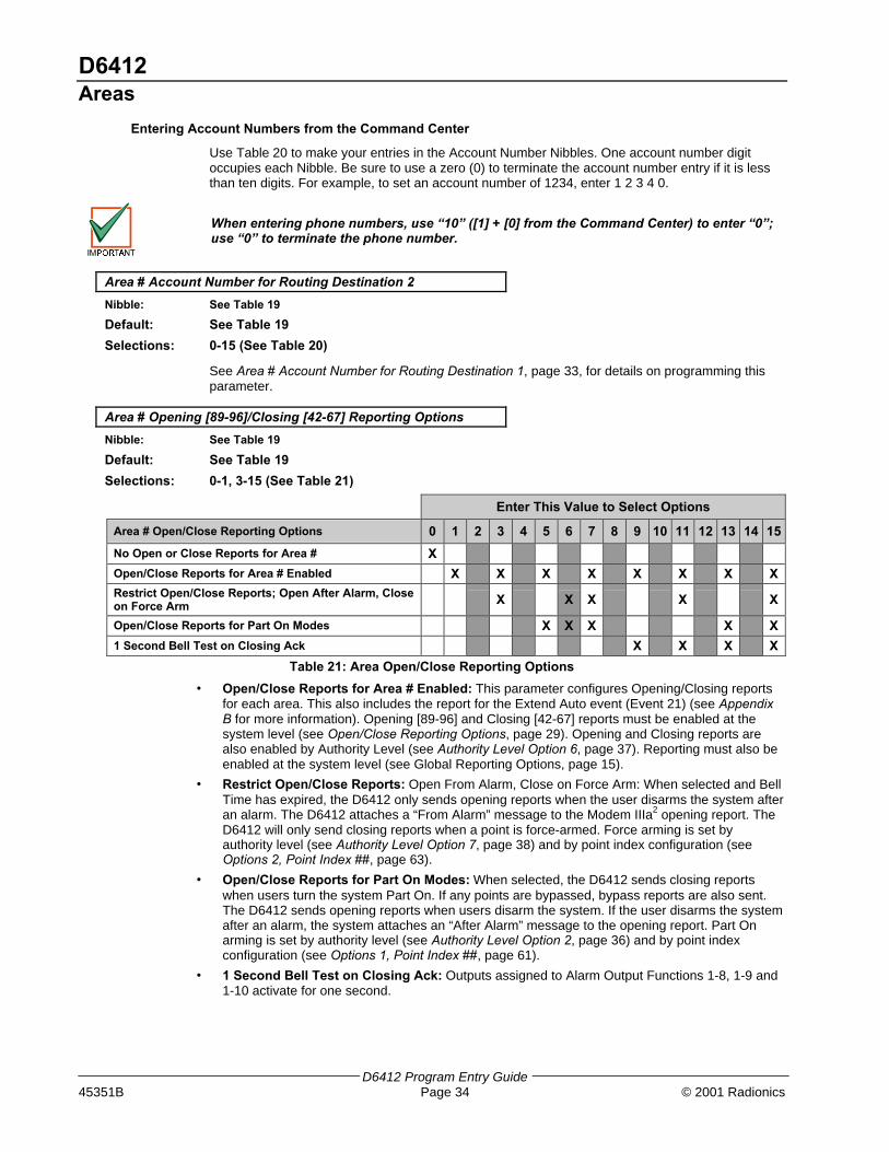
D6412Areas
D6412 Program Entry Guide45351B Page 34 © 2001 Radionics
Entering Account Numbers from the Command Center
Use Table 20 to make your entries in the Account Number Nibbles. One account number digitoccupies each Nibble. Be sure to use a zero (0) to terminate the account number entry if it is lessthan ten digits. For example, to set an account number of 1234, enter 1 2 3 4 0.
When entering phone numbers, use “10” ([1] + [0] from the Command Center) to enter “0”;use “0” to terminate the phone number.
Area # Account Number for Routing Destination 2
Nibble: See Table 19
Default: See Table 19
Selections: 0-15 (See Table 20)
See Area # Account Number for Routing Destination 1, page 33, for details on programming thisparameter.
Area # Opening [89-96]/Closing [42-67] Reporting Options
Nibble: See Table 19
Default: See Table 19
Selections: 0-1, 3-15 (See Table 21)
Enter This Value to Select Options
Area # Open/Close Reporting Options 0 1 2 3 4 5 6 7 8 9 10 11 12 13 14 15
No Open or Close Reports for Area # X
Open/Close Reports for Area # Enabled X X X X X X X X
Restrict Open/Close Reports; Open After Alarm, Closeon Force Arm X X X X X
Open/Close Reports for Part On Modes X X X X X
1 Second Bell Test on Closing Ack X X X X
Table 21: Area Open/Close Reporting Options
• Open/Close Reports for Area # Enabled: This parameter configures Opening/Closing reportsfor each area. This also includes the report for the Extend Auto event (Event 21) (see AppendixB for more information). Opening [89-96] and Closing [42-67] reports must be enabled at thesystem level (see Open/Close Reporting Options, page 29). Opening and Closing reports arealso enabled by Authority Level (see Authority Level Option 6, page 37). Reporting must also beenabled at the system level (see Global Reporting Options, page 15).
• Restrict Open/Close Reports: Open From Alarm, Close on Force Arm: When selected and BellTime has expired, the D6412 only sends opening reports when the user disarms the system afteran alarm. The D6412 attaches a “From Alarm” message to the Modem IIIa2 opening report. TheD6412 will only send closing reports when a point is force-armed. Force arming is set byauthority level (see Authority Level Option 7, page 38) and by point index configuration (seeOptions 2, Point Index ##, page 63).
• Open/Close Reports for Part On Modes: When selected, the D6412 sends closing reportswhen users turn the system Part On. If any points are bypassed, bypass reports are also sent.The D6412 sends opening reports when users disarm the system. If the user disarms the systemafter an alarm, the system attaches an “After Alarm” message to the opening report. Part Onarming is set by authority level (see Authority Level Option 2, page 36) and by point indexconfiguration (see Options 1, Point Index ##, page 61).
• 1 Second Bell Test on Closing Ack: Outputs assigned to Alarm Output Functions 1-8, 1-9 and1-10 activate for one second.

D6412Authority Levels
D6412 Program Entry Guide© 2001 Radionics Page 35 45351B
Lock Area # Reporting
Nibble: See Table 19
Default: 0Selections: 0 = Lock Area Reporting Disabled
1 = Lock Area Reports to Routing Destination 12 = Lock Area Reports to Routing Destination 2
Use this parameter to lock area reporting to either Routing Destination 1 or Routing Destination 2. Ifyou enable this feature for an area, all reports for that area are sent to the selected destination.Routing parameters for the individual reports are ignored.For example, if you set this parameter to 1, all reports in the area are sent to Destination 1. If youset this parameter to 2, all reports in the area are sent to Destination 2.
2.8 Authority Level ConfigurationThe Authority Level determines which functions are available to system users. Each user isassigned an Authority Level. Use the parameters in this section to configure each of the fourauthority levels available in the D6412.See Appendix D: Operation Guide, page 111, for a explanation of the commands listed below ineach Authority Level Configuration option.Authority Level defaults consists of the following options:
• Authority Level 1: All options except for Option 5.
• Authority Level 2: All options except for Option 5.
• Authority Level 3: All options except for Options 5, 8, 10 & 11.
• Authority Level 4: All options except 7-15.
Authority Level Config Option 1: Cmd 1/All On
Nibble: 0364
Default: 15Selections: 0-15 (See Table 22)
Enter This Value to Select Options
Authority Level Option 0 1 2 3 4 5 6 7 8 9 10 11 12 13 14 15
No Passcode Required X
Assign to Authority Level 1 X X X X X X X X
Assign to Authority Level 2 X X X X X X X X
Assign to Authority Level 3 X X X X X X X X
Assign to Authority Level 4 X X X X X X X X
Table 22: Authority Level Option 1-3 Parameter Options
This parameter determines the required authority level to perform the following functions:
− Cmd 1 – All On with Delay
− Cmd 1 – All On with Delay, No Exit Tone*
− Cmd 1 – All On with No Delay
− All On Key – All On with Delay
− All On Key – All On with Delay, No Exit Tone*
− All On Key – All On with No Delay
If a passcode is required and not entered, the system asks for it after the command is entered.
* Exit Time is doubled when arming the system All On with Delay, Silent. See pages 114 in thismanual for instructions.

D6412Authority Levels
D6412 Program Entry Guide45351B Page 36 © 2001 Radionics
Authority Level Config Option 2: Cmd 2/Part On
Nibble: 0365
Default: 15Selections: 0-15 (See Table 22)
This parameter determines the required authority level to perform the following functions:
− Cmd 2 – Part On with Delay
− Cmd 2 – Part On with Delay, No Exit Tone*
− Cmd 2 – Part On with No Delay
− Part On Key – Part On with Delay
− Part On Key – Part On with Delay, No Exit Tone*
− Part On Key – Part On with No Delay
If a passcode is required and not entered, the system asks for it after the command is entered.Points must be configured for Part On arming. See Options 1, Point Index ##, page 61.
* Exit Time is doubled when arming the system All On with Delay, Silent. See pages 114 in thismanual for instructions.
Authority Level Config Option 3: Cmd 3/Part 2 On
Nibble: 0366
Default: 15
Selections: 0-15 (See Table 22)
This parameter determines the required authority level to perform the following functions:
− Cmd 3 – Part 2 On with Delay
− Cmd 3 – Part 2 On with Delay, Silent
− Cmd 3 – Part 2 On with No Delay
If a passcode is required and not entered, the system asks for it after the command is entered.
Authority Level Config Option 4: Disarming the System
Nibble: 0367
Default: 15
Selections: 0-15 (See Table 23)
Enter This Value to Select Options
Authority Level Option 0 1 2 3 4 5 6 7 8 9 10 11 12 13 14 15
Disarm Not Assigned X
Assign to Authority Level 1 X X X X X X X X
Assign to Authority Level 2 X X X X X X X X
Assign to Authority Level 3 X X X X X X X X
Assign to Authority Level 4 X X X X X X X X
Table 23: Authority Level Option 4 Parameter Options
This parameter determines which authority levels can disarm (turn off) the system.
If 0 (Disarm Not Assigned) is selected for Authority Level Option 4 (Nibble 0367), you willnot be able to disarm the system.

D6412Authority Levels
D6412 Program Entry Guide© 2001 Radionics Page 37 45351B
Authority Level Config Option 5: One-Time Disarm
Nibble: 0368
Default: 8
Selections: 0-15 (See Table 24)
Enter This Value to Select Options
Authority Level Option 0 1 2 3 4 5 6 7 8 9 10 11 12 13 14 15
One Time Disarm Not Assigned X
Assign to Authority Level 1 X X X X X X X X
Assign to Authority Level 2 X X X X X X X X
Assign to Authority Level 3 X X X X X X X X
Assign to Authority Level 4 X X X X X X X X
Table 24: Authority Level Option 5 Parameter Options
If an authority level can disarm the system (see Authority Level Option 4, page 36), use thisparameter to restrict that authority level to One-time Disarm (can only disarm the system once).
Authority Level Config Option 6: Disable Open/Close Reports
Nibble: 0369
Default: 0
Selections: 0-15 (See Table 25)
Enter This Value to Select Options
Authority Level Option 0 1 2 3 4 5 6 7 8 9 10 11 12 13 14 15
Send Open/Close For All Levels X
Assign to Authority Level 1 X X X X X X X X
Assign to Authority Level 2 X X X X X X X X
Assign to Authority Level 3 X X X X X X X X
Assign to Authority Level 4 X X X X X X X X
Table 25: Authority Level Option 6 Parameter Options
No Open/Close reports are sent for the Authority Level(s) selected at this parameter. For example,if Open/Close Reports are enabled for an area and Open/Close reports are disabled for AuthorityLevel 1 in this parameter, the D6412 will send Open/Close reports for users assigned to AuthorityLevels 2, 3 and 4. It will not send Open/Close reports for users assigned to Authority Level 1, eventhough Open/Close reports are enabled for the area.
See the following parameters to properly enable/disable Open/Close Reporting: RoutingDestinations, page 8; Global Reporting Options, page 15; Open/Close Reporting Options, page 29;and Area # Open/Close Reporting Options, page 34.
When the authority level is set to 15, no Open/Close reports are sent even if the arming key(All On, Part On, Cmd 1, Cmd 2 or Cmd 3) does not require a passcode.
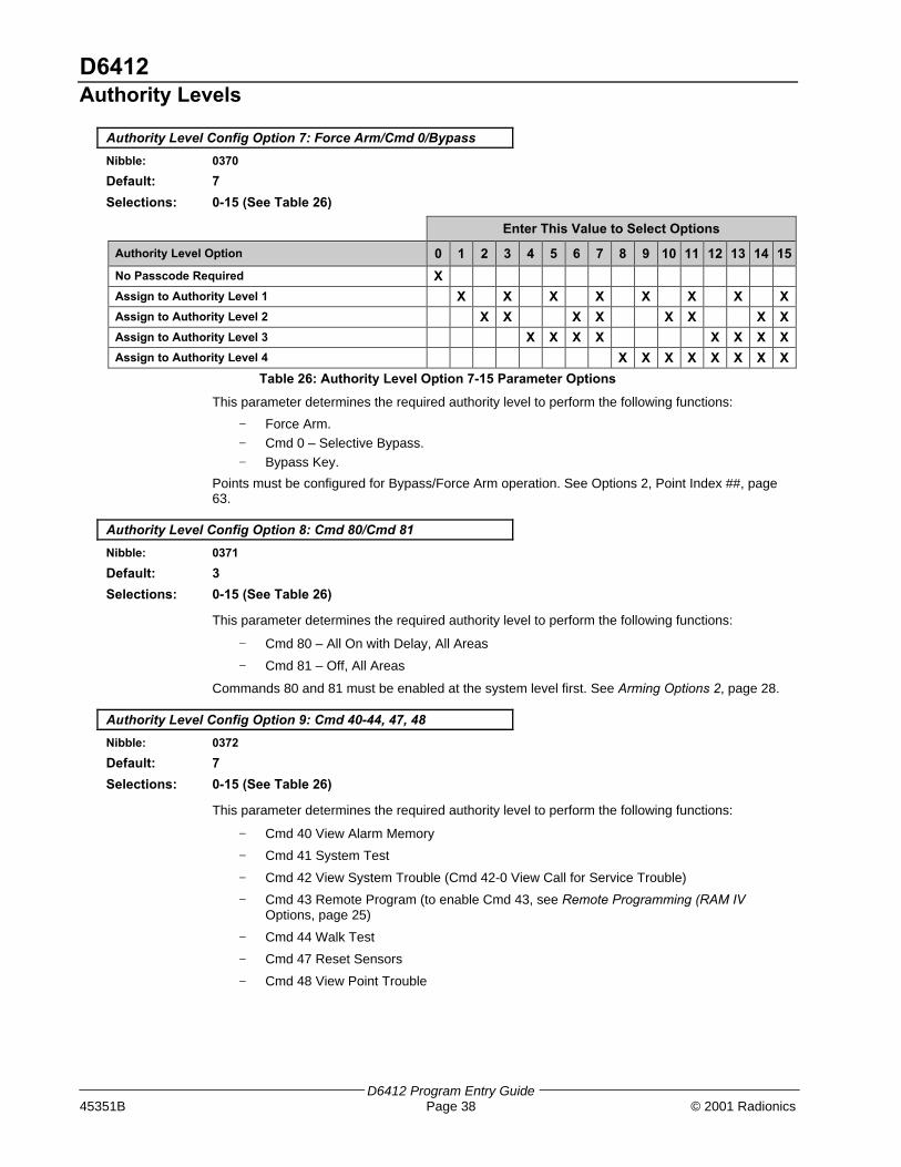
D6412Authority Levels
D6412 Program Entry Guide45351B Page 38 © 2001 Radionics
Authority Level Config Option 7: Force Arm/Cmd 0/Bypass
Nibble: 0370
Default: 7
Selections: 0-15 (See Table 26)
Enter This Value to Select Options
Authority Level Option 0 1 2 3 4 5 6 7 8 9 10 11 12 13 14 15
No Passcode Required X
Assign to Authority Level 1 X X X X X X X X
Assign to Authority Level 2 X X X X X X X X
Assign to Authority Level 3 X X X X X X X X
Assign to Authority Level 4 X X X X X X X X
Table 26: Authority Level Option 7-15 Parameter Options
This parameter determines the required authority level to perform the following functions:
− Force Arm.
− Cmd 0 – Selective Bypass.
− Bypass Key.
Points must be configured for Bypass/Force Arm operation. See Options 2, Point Index ##, page63.
Authority Level Config Option 8: Cmd 80/Cmd 81
Nibble: 0371
Default: 3
Selections: 0-15 (See Table 26)
This parameter determines the required authority level to perform the following functions:
− Cmd 80 – All On with Delay, All Areas
− Cmd 81 – Off, All Areas
Commands 80 and 81 must be enabled at the system level first. See Arming Options 2, page 28.
Authority Level Config Option 9: Cmd 40-44, 47, 48
Nibble: 0372
Default: 7
Selections: 0-15 (See Table 26)
This parameter determines the required authority level to perform the following functions:
− Cmd 40 View Alarm Memory
− Cmd 41 System Test
− Cmd 42 View System Trouble (Cmd 42-0 View Call for Service Trouble)
− Cmd 43 Remote Program (to enable Cmd 43, see Remote Programming (RAM IVOptions, page 25)
− Cmd 44 Walk Test
− Cmd 47 Reset Sensors
− Cmd 48 View Point Trouble
D6412Authority Levels
D6412 Program Entry Guide© 2001 Radionics Page 39 45351B
Authority Level Config Option 10: Cmd 45, 52, 53, 56, 58, 62,63, 65, 83, 84
Nibble: 0373
Default: 3Selections: 0-15 (See Table 26)
This parameter determines the required authority level to perform the following functions:− Cmd 45 - Set Time and Date (send Date/Time Change [73] report)− Cmd 52 - Change Skeds (see Skeds, page 79, for information on Skeds)− Cmd 53 – Renew One-Time Passcodes− Cmd 56 – Change (Add) Other Passcodes− Cmd 58 - Delete Passcodes− Cmd 62 - Set Watch Tone− Cmd 63 - Set Watch Points− Cmd 65 - Set Part 2 Points− Cmd 83 - Auto-Call Forwarding Enable, Digits to dial at All On− Cmd 84 - Auto-Call Forwarding Disable, Digits to dial at disarm
Authority Level Config Option 11: Cmd 50
Nibble: 0374
Default: 3Selections: 0-15 (See Table 26)
This parameter determines the required authority level to perform the Cmd 50 – Move to Areafunction.
Authority Level Config Option 12: Cmd 51
Nibble: 0375
Default: 7Selections: 0-15 (See Table 26)
This parameter determines the required authority level to perform the Cmd 51 – Extend close(Automatic Arming) function.
Authority Level Config Option 13: Cmd 49, 54, 61, 82
Nibble: 0376
Default: 7Selections: 0-15 (See Table 26)
This parameter determines the required authority level to perform the following functions:− Cmd 49 – Adjust command center keystroke volume and lighting− Cmd 54 – Change or reset outputs− Cmd 61 – Watch toggle Off/On− Cmd 82 – Auto-Forward – Enable/Disable
Authority Level Config Option 14: Cmd 55
Nibble: 0377
Default: 7Selections: 0-15 (See Table 26)
This parameter determines the required authority level to perform the Cmd 55 – Passcode Changefunction.
Authority Level Config Option 15: Cmd 85
Nibble: 0378
Default: 7Selections: 0-15 (See Table 26)
This parameter determines the required authority level to perform the Cmd 85 – View Log function.

D6412Passcode Configuration, Installer Passcode
D6412 Program Entry Guide45351B Page 40 © 2001 Radionics
2.9 Passcode Configuration, Installer Passcode
Passcode Length
Nibble: 0379
Default: 4
Selections: 3 - 7
This parameter determines the number of digits in a passcode. All user passcodes and the installerpasscode follow this length. The RAM passcode, page 13, is not affected by the setting made inthis parameter.
If the passcode length is shortened after passcodes are entered, duplicate passcodescould be created (for example, passcodes 1235 and 1238 would both become 123).
If the passcode is lengthened, some passcodes may be disabled (for example, passcode396, if lengthened to five digits, would become 396FF [F=blank] thus disabling thepasscode since F cannot be entered at a command center).
User Tamper Options
Nibble: 0380
Default: 1
Selections: 0-3 (See Table 27)
Enter This Value to Select Options
User Tamper Option 0 1 2 3 4 5 6 7 8 9 10 11 12 13 14 15
No User Tamper Alert Events X
User Tamper [156] Reports Enabled X X
User Tamper Activates Burg Alarm Output X X
Reserved
Reserved
Table 27: User Tamper Options
A user tamper event is:
− a user entering a passcode that is not in the system (the user must enter the invalid codethe number of times shown in User Tamper Retry Count, page 41).
− a user entering a passcode that is in the system but does not have the authority for thedesired function
• User Tamper Reports Enabled: User Tamper events appear at all command centers assignedto the area where the user is accessing the system. User Tamper [156] reports and user tamperactivated alarm outputs are tied to the command center’s area. If only the User Tamper [156]Reports Enabled option is selected and there is a user tamper event, the text command centerwhere the event occurs shows Keypad Locked.
• User Tamper Activates Burg Alarm Output: If the burglary alarm output (steady alarm output )is selected and there is a user tamper event, the text command center where the user tamperoccurred will show Keypad locked! Other text command centers in the area will show UsrTamper Alarm, Enter code to silence. While the command center is locked out, anykey pressed produces an error tone (for text and LED command centers). Selecting “UserTamper Activates Burg Alarm Output” specifically activates output functions 1-8, 1-9 and 1-10.See page Table 53, “Output Function Types,” page 74, for descriptions of these output functions.
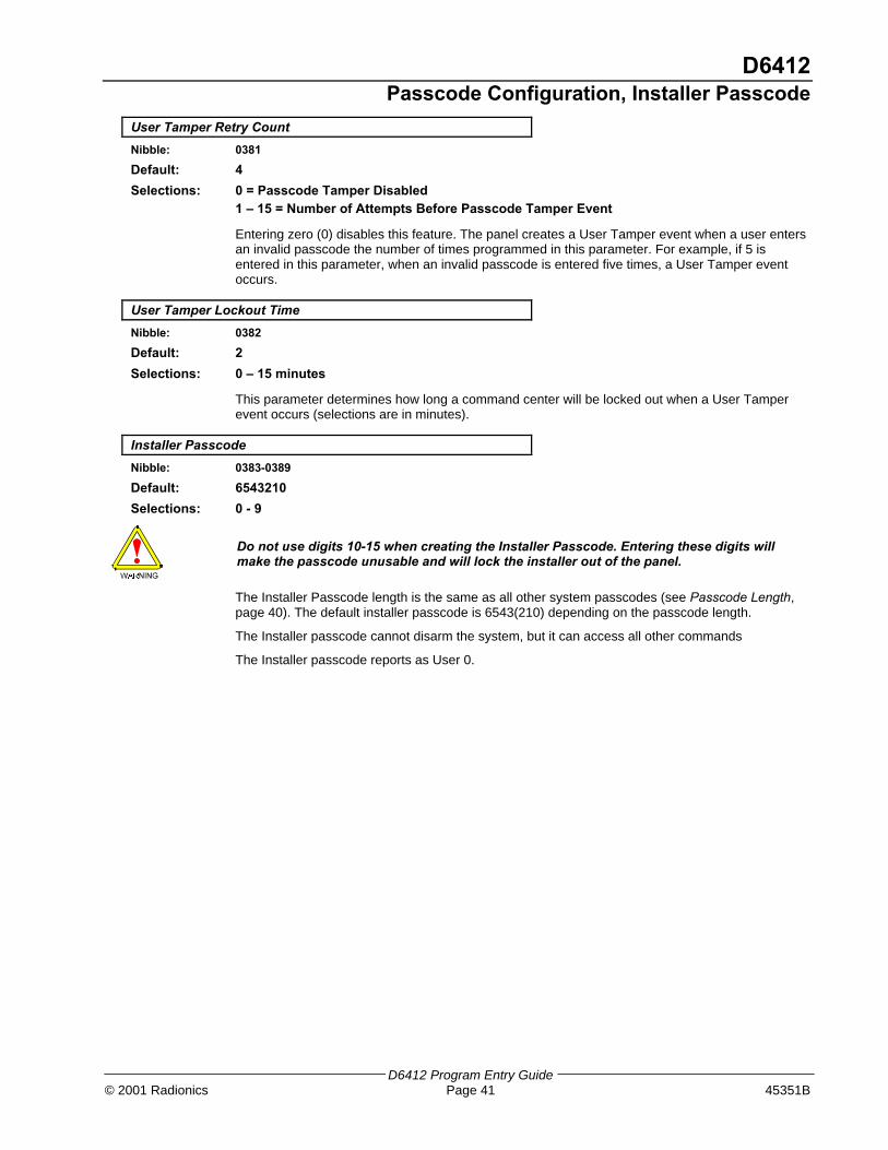
D6412Passcode Configuration, Installer Passcode
D6412 Program Entry Guide© 2001 Radionics Page 41 45351B
User Tamper Retry Count
Nibble: 0381
Default: 4
Selections: 0 = Passcode Tamper Disabled1 – 15 = Number of Attempts Before Passcode Tamper Event
Entering zero (0) disables this feature. The panel creates a User Tamper event when a user entersan invalid passcode the number of times programmed in this parameter. For example, if 5 isentered in this parameter, when an invalid passcode is entered five times, a User Tamper eventoccurs.
User Tamper Lockout Time
Nibble: 0382
Default: 2
Selections: 0 – 15 minutes
This parameter determines how long a command center will be locked out when a User Tamperevent occurs (selections are in minutes).
Installer Passcode
Nibble: 0383-0389
Default: 6543210
Selections: 0 - 9
Do not use digits 10-15 when creating the Installer Passcode. Entering these digits willmake the passcode unusable and will lock the installer out of the panel.
The Installer Passcode length is the same as all other system passcodes (see Passcode Length,page 40). The default installer passcode is 6543(210) depending on the passcode length.
The Installer passcode cannot disarm the system, but it can access all other commands
The Installer passcode reports as User 0.

D6412Users
D6412 Program Entry Guide45351B Page 42 © 2001 Radionics
2.10 UsersThis section details configuring each user’s passcode, authority level and area assignment. The D6412 systemsupports up to 32 users. Table 28 outlines the User parameters and the respective Nibbles for each User. Seepage 44 for User programming parameters.
PasscodeAuthority
LevelArea
User # Digit 1 Digit 2 Digit 3 Digit 4 Digit 5 Digit 6 Digit 7 Selection Selection
1 Nibble0390(1)
Nibble0391(2)
Nibble0392(3)
Nibble0393(4)
Nibble0394(5)
Nibble0395(6)
Nibble0396(7)
Nibble0397(1)
Nibble0398(15)
2 Nibble0399(0)
Nibble0400(0)
Nibble0401(0)
Nibble0402(0)
Nibble0403(0)
Nibble0404(0)
Nibble0405(0)
Nibble0406(0)
Nibble0407(0)
3 Nibble0408(0)
Nibble0409(0)
Nibble0410(0)
Nibble0411(0)
Nibble0412(0)
Nibble0413(0)
Nibble0414(0)
Nibble0415(0)
Nibble0416(0)
4 Nibble0417(0)
Nibble0418(0)
Nibble0419(0)
Nibble0420(0)
Nibble0421(0)
Nibble0422(0)
Nibble0423(0)
Nibble0424(0)
Nibble0425(0)
5 Nibble0426(0)
Nibble0427(0)
Nibble0428(0)
Nibble0429(0)
Nibble0430(0)
Nibble0431(0)
Nibble0432(0)
Nibble0433(0)
Nibble0434(0)
6 Nibble0435(0)
Nibble0436(0)
Nibble0437(0)
Nibble0438(0)
Nibble0439(0)
Nibble0440(0)
Nibble0441(0)
Nibble0442(0)
Nibble0443(0)
7 Nibble0444(0)
Nibble0445(0)
Nibble0446(0)
Nibble0447(0)
Nibble0448(0)
Nibble0449(0)
Nibble0450(0)
Nibble0451(0)
Nibble0452(0)
8 Nibble0453(0)
Nibble0454(0)
Nibble0455(0)
Nibble0456(0)
Nibble0457(0)
Nibble0458(0)
Nibble0459(0)
Nibble0460(0)
Nibble0461(0)
9 Nibble0462(0)
Nibble0463(0)
Nibble0464(0)
Nibble0465(0)
Nibble0466(0)
Nibble0467(0)
Nibble0468(0)
Nibble0469(0)
Nibble0470(0)
10 Nibble0471(0)
Nibble0472(0)
Nibble0473(0)
Nibble0474(0)
Nibble0475(0)
Nibble0476(0)
Nibble0477(0)
Nibble0478(0)
Nibble0479(0)
11 Nibble0480(0)
Nibble0481(0)
Nibble0482(0)
Nibble0483(0)
Nibble0484(0)
Nibble0485(0)
Nibble0486(0)
Nibble0487(0)
Nibble0488(0)
12 Nibble0489(0)
Nibble0490(0)
Nibble0491(0)
Nibble0492(0)
Nibble0493(0)
Nibble0494(0)
Nibble0495(0)
Nibble0496(0)
Nibble0497(0)
13 Nibble0498(0)
Nibble0499(0)
Nibble0500(0)
Nibble0501(0)
Nibble0502(0)
Nibble0503(0)
Nibble0504(0)
Nibble0505(0)
Nibble0506(0)
14 Nibble0507(0)
Nibble0508(0)
Nibble0509(0)
Nibble0510(0)
Nibble0511(0)
Nibble0512(0)
Nibble0513(0)
Nibble0514(0)
Nibble0515(0)
15 Nibble0516(0)
Nibble0517(0)
Nibble0518(0)
Nibble0519(0)
Nibble0520(0)
Nibble0521(0)
Nibble0522(0)
Nibble0523(0)
Nibble0524(0)
16 Nibble0525(0)
Nibble0526(0)
Nibble0527(0)
Nibble0528(0)
Nibble0529(0)
Nibble0530(0)
Nibble0531(0)
Nibble0532(0)
Nibble0533(0)
17 Nibble0534(0)
Nibble0535(0)
Nibble0536(0)
Nibble0537(0)
Nibble0538(0)
Nibble0539(0)
Nibble0540(0)
Nibble0541(0)
Nibble0542(0)
Table 28: User Passcode, Authority Level & Area Programming

D6412Users
D6412 Program Entry Guide© 2001 Radionics Page 43 45351B
Passcode AuthorityLevel
Area
User # Digit 1 Digit 2 Digit 3 Digit 4 Digit 5 Digit 6 Digit 7 Selection Selection18 Nibble
0543(0)
Nibble0544(0)
Nibble0545(0)
Nibble0546(0)
Nibble0547(0)
Nibble0548(0)
Nibble0549(0)
Nibble0550(0)
Nibble0551(0)
19 Nibble0552(0)
Nibble0553(0)
Nibble0554(0)
Nibble0555(0)
Nibble0556(0)
Nibble0557(0)
Nibble0558(0)
Nibble0559(0)
Nibble0560(0)
20 Nibble0561(0)
Nibble0562(0)
Nibble0563(0)
Nibble0564(0)
Nibble0565(0)
Nibble0566(0)
Nibble0567(0)
Nibble0568(0)
Nibble0569(0)
21 Nibble0570(0)
Nibble0571(0)
Nibble0572(0)
Nibble0573(0)
Nibble0574(0)
Nibble0575(0)
Nibble0576(0)
Nibble0577(0)
Nibble0578(0)
22 Nibble0579(0)
Nibble0580(0)
Nibble0581(0)
Nibble0582(0)
Nibble0583(0)
Nibble0584(0)
Nibble0585(0)
Nibble0586(0)
Nibble0587(0)
23 Nibble0588(0)
Nibble0589(0)
Nibble0590(0)
Nibble0591(0)
Nibble0592(0)
Nibble0593(0)
Nibble0594(0)
Nibble0595(0)
Nibble0596(0)
24 Nibble0597(0)
Nibble0598(0)
Nibble0599(0)
Nibble0600(0)
Nibble0601(0)
Nibble0602(0)
Nibble0603(0)
Nibble0604(0)
Nibble0605(0)
25 Nibble0606(0)
Nibble0607(0)
Nibble0608(0)
Nibble0609(0)
Nibble0610(0)
Nibble0611(0)
Nibble0612(0)
Nibble0613(0)
Nibble0614(0)
26 Nibble0615(0)
Nibble0616(0)
Nibble0617(0)
Nibble0618(0)
Nibble0619(0)
Nibble0620(0)
Nibble0621(0)
Nibble0622(0)
Nibble0623(0)
27 Nibble0624(0)
Nibble0625(0)
Nibble0626(0)
Nibble0627(0)
Nibble0628(0)
Nibble0629(0)
Nibble0630(0)
Nibble0631(0)
Nibble0632(0)
28 Nibble0633(0)
Nibble0634(0)
Nibble0635(0)
Nibble0636(0)
Nibble0637(0)
Nibble0638(0)
Nibble0639(0)
Nibble0640(0)
Nibble0641(0)
29 Nibble0642(0)
Nibble0643(0)
Nibble0644(0)
Nibble0645(0)
Nibble0646(0)
Nibble0647(0)
Nibble0648(0)
Nibble0649(0)
Nibble0650(0)
30 Nibble0651(0)
Nibble0652(0)
Nibble0653(0)
Nibble0654(0)
Nibble0655(0)
Nibble0656(0)
Nibble0657(0)
Nibble0658(0)
Nibble0659(0)
31 Nibble0660(0)
Nibble0661(0)
Nibble0662(0)
Nibble0663(0)
Nibble0664(0)
Nibble0665(0)
Nibble0666(0)
Nibble0667(0)
Nibble0668(0)
32 Nibble0669(0)
Nibble0670(0)
Nibble0671(0)
Nibble0672(0)
Nibble0673(0)
Nibble0674(0)
Nibble0675(0)
Nibble0676(0)
Nibble0677(0)
Table 28: (cont.): User Passcode, Authority Level & Area Programming
The D6412 reserves the following User IDs for automated functions:
− User ID 252: Sked operation
− User ID 253: Remote telephone communication
− User ID 254: RAM IV communication
− User ID 255: Keyswitch operation

D6412Users
D6412 Program Entry Guide45351B Page 44 © 2001 Radionics
Passcode, User #
Nibble: See Table 28
Default: See Table 28
Selections: 0 - 9
Use the Passcode parameter to enter a passcode for each user (up to 32). The passcode lengthparameter determines the number of digits in the passcodes.
Since the default passcode length is four digits, the default passcode for User 1 is 1234. If thepasscode length is increased to five digits, the default passcode for User 1 becomes 12345. If sixdigits are selected, the default passcode becomes 123456, and if the maximum number of digits isprogrammed, the default passcode becomes 1234567.
Do not use digits 10-15 when creating a User Passcode. Entering these digits will make thepasscode unusable and will lock the user out of the panel.
Authority Level, User #
Nibble: See Table 28
Default: See Table 28
Selections: 0 (disabled)1 = Authority Level 12 = Authority Level 23 = Authority Level 34 = Authority Level 4
This parameter assigns an authority level to each user. The Authority Level assigns functions to theuser’s passcode and RF keyfob (see Authority Levels, page 35). See RF Keyfobs, page 89, for adescription of RF keyfobs and how to assign them to users.
Area Option, User #
Nibble: See Table 28
Default: See Table 28
Selections: 0-15 (See Table 29)
Enter This Value to Select Options
Area Option 0 1 2 3 4 5 6 7 8 9 10 11 12 13 14 15
Not Assigned to an Area X
Assigned to Area 1 X X X X X X X X
Assigned to Area 2 X X X X X X X X
Assigned to Area 3 X X X X X X X X
Assigned to Area 4 X X X X X X X X
Table 29: Area Options
Assigning passcodes to multiple areas allows users to view and operate multiple areas at a singlecommand center. This is a passcode/user function and is not a command center scope function(there is no command center scope in the D6412).

D6412Command Centers
D6412 Program Entry Guide© 2001 Radionics Page 45 45351B
2.11 Command CentersWired command centers 1 to 8 are fixed at SDI addresses 1 to 8.
All command centers (and other SDI devices) are fully supervised. Supervision reports (missing, tamper, etc.)follow the System Status Report routing.
CommandCenter
CommandCenter Options
Area DIP SwitchSettings*
1 Nibble 06783
Nibble 06791
1, MODE
2 Nibble 06803
Nibble 06810
2, MODE
3 Nibble 06823
Nibble 06830
1, 2, MODE
4 Nibble 06843
Nibble 06850
4, MODE
5 Nibble 06863
Nibble 06870
1, 4, MODE
6 Nibble 06883
Nibble 06890
2, 4, MODE
7 Nibble 06903
Nibble 06910
1, 2, 4, MODE
8 Nibble 06923
Nibble 06930
8, MODE
Table 30: Command Center Programming Parameter Nibbles and Default Values
* The switches listed in this column are the switches that must be placed in the ON position. See Figure 2 forcorrect DIP switch orientation.
ON
1 2 3 4 5 6
1 2 4 8 16 MODE
ADDRESS
OFFON
Figure 2: Command Center DIP Switch Orientation
See Table 31 for Command Center DIP Switch addressing.
DIP Switch Settings
DIP Switches S1 S2 S3 S4 S5 S6
SDI Address 1 2 4 8 16 MODE
0*
1 ON ON
2 ON ON
3 ON ON ON
4 ON ON
5 ON ON ON
6 ON ON ON
7 ON ON ON ON
8 ON ON
Table 31: DIP Switch Settings for Command Center Addressing
* Address 0 is reservedfor the installer’s keypad.See the D6412 InstallationGuide (P/N: 45349) forinformation on theInstaller’s Keypad.

D6412Command Centers
D6412 Program Entry Guide45351B Page 46 © 2001 Radionics
Command Center # Options
Nibble: See Table 30
Default: See Table 30Selections: 0-3, 8-11 (See Table 32)
Enter This Value to Select Options
Command Center Option 0 1 2 3 4 5 6 7 8 9 10 11 12 13 14 15
No Command Center Options X
Beep Command Center on System Trouble X X X X
Enable Exit Tone X X X X
Reserved
Don’t Show Point Status on Command Centers X X X X
Table 32: Command Center Options
• Beep Command Center on System Trouble: sounds a tone at the command center when asystem trouble occurs.
For UL Listed installations, Beep Command Center on System Trouble must be turnedon.
• Enable Exit Tone: sounds the exit delay tone at this command center when exit delay is active.
• Don’t Show Point Status on Command Centers: if not selected (no “X” in option box for thisfeature), the text command center displays “OK for All On” or “OK for Part On” across the secondline. This indicates that all points are normal and the system is ready to arm All On or Part On.
− If a point (controlled or 24-hour non-fire) is faulted (either open or shorted), the Area IdleText for this point’s assigned area replaces the “OK for All On” message.
If “Don’t Show Point Status on Command Centers” is selected, the default Area IdleText displays as “Not Ready.” If no points are faulted, the Area Idle Text must bechanged. See “Programming Text Nibbles”, page 131, for text entry instructions.
− If a controlled point not configured for Part On arming is faulted (either open or shorted),“OK for Part On” replaces “OK for All On” on the text command center’s display. Thesystem may be armed Part On, but cannot be armed All On until the faulted point isrestored. See Options 1, Point Index ##, page 61, for point index configuration details.
This option configures the LED command center to not show point status when its area is Off(disarmed). Users must press the [*] key to see point status.
Command Center # Area
Nibble: See Table 30
Default: See Table 30Selections: 0 = Disable
1 = Assign Command Center to Area 12 = Assign Command Center to Area 23 = Assign Command Center to Area 34 = Assign Command Center to Area 4
Choose one area to assign the command center to. Users (passcodes) can be assigned to multipleareas.
The Move command (Cmd 50) allows users (passcodes) assigned to multiple areas to view thoseareas from one command center. There is no command center scope in this product.

D6412ABC Keys and Duress Parameters
D6412 Program Entry Guide© 2001 Radionics Page 47 45351B
2.12 ABC Keys and Duress ParametersThe parameters in this section configure the ABC keys and the Duress function for all command centers andareas. Each key has 16 characters of programmable text that is displayed when the key is activated (press twiceto activate). See System Text, page 85, and Programming Text Nibbles, page 131, for information on SystemText programming and Text Nibble entries.
[A] Key Area Option
Nibble: 0694
Default: 15
Selections: 0-15 (See Table 33)
Enter This Value to Select Options
A Key Area Option 0 1 2 3 4 5 6 7 8 9 10 11 12 13 14 15
Disabled for All Areas X
A Key Works for Area 1 X X X X X X X X
A Key Works for Area 2 X X X X X X X X
A Key Works for Area 3 X X X X X X X X
A Key Works for Area 4 X X X X X X X X
Table 33: [A] Key Area Options
Use this parameter to assign areas to the [A] Key. [A] Key reports as Point 100 for all areas.
[A] Key Alarm Response
Nibble: 0695
Default: 0
Selections: 0 = No Alarm Response1 = Activate Fire Alarm Response2 = Activate Panic Alarm Response3 = Activate Emergency Response
The parameter determines the alarm response for the [A] key.
• Fire Alarm Response: displays Fire Alarm Key # at the text command centers. Ifprogrammed, the panel sends a Fire Alarm [75] report and activates the Fire Alarm output.
• Panic Alarm Response: nothing is displayed and no sounds are emitted at the commandcenters. If programmed, a Panic [6] report is sent and the Burglary Alarm output is activated.
• Emergency Alarm Response: displays Alarm Key # at the text command centers. Ifprogrammed, an Emergency Alarm [4] report is sent and the Burglary Alarm output is activated.
[B] Key Area Option
Nibble: 0696
Default: 15Selections: 0-15 (See Table 34)
Enter This Value to Select Options
B Key Area Option 0 1 2 3 4 5 6 7 8 9 10 11 12 13 14 15
Disabled for All Areas X
B Key Works for Area 1 X X X X X X X X
B Key Works for Area 2 X X X X X X X X
B Key Works for Area 3 X X X X X X X X
B Key Works for Area 4 X X X X X X X X
Table 34: [B] Key Area Options
Use this parameter to assign areas to the [B] Key. [B] Key reports as Point 101 for all areas.

D6412ABC Keys and Duress Parameters
D6412 Program Entry Guide45351B Page 48 © 2001 Radionics
[B] Key Alarm Response
Nibble: 0697
Default: 0
Selections: 0 = No Alarm Response1 = Activate Fire Alarm Response2 = Activate Panic Alarm Response3 = Activate Emergency Response
See [A] Key Alarm Response, page 47, for more information about these parameter options.
[C] Key Area Option
Nibble: 0698
Default: 15
Selections: 0-15 (See Table 35)
Enter This Value to Select Options
C Key Area Option 0 1 2 3 4 5 6 7 8 9 10 11 12 13 14 15
Disabled for All Areas X
C Key Works for Area 1 X X X X X X X X
C Key Works for Area 2 X X X X X X X X
C Key Works for Area 3 X X X X X X X X
C Key Works for Area 4 X X X X X X X X
Table 35: [C] Key Area Options
Use this parameter to assign areas to the [C] Key. [C] Key reports as Point 102 for all areas.
[C] Key Alarm Response
Nibble: 0699
Default: 0
Selections: 0 = No Alarm Response1 = Activate Fire Alarm Response2 = Activate Panic Alarm Response3 = Activate Emergency Response
See [A] Key Alarm Response, page 47, for more information about these parameter options.
Alarm Output Option for ABC Keys
Nibble: 0700
Default: 0
Selections: 0-7 (See Table 36)
Enter This Value to Select Options
Alarm Output Option 0 1 2 3 4 5 6 7 8 9 10 11 12 13 14 15
No Alarm Output for A B C Keys X
Alarm Output for A Key X X X X
Alarm Output for B Key X X X X
Alarm Output for C Key X X X X
Reserved
Table 36: Alarm Output Options
Use this parameter to assign an alarm output option to the ABC keys. The alarm output will activatefor the response type assigned to each key. See [A] Key Alarm Response, page 47. This is a globalparameter that affects all areas.

D6412ABC Keys and Duress Parameters
D6412 Program Entry Guide© 2001 Radionics Page 49 45351B
ABC Key Reports, Acknowledgement Beep at CommandCenter Options
Nibble: 0701
Default: 0
Selections: 0-15 (See Table 37)
Enter This Value to Select Options
ABC Key Report & Ack Beep Option 0 1 2 3 4 5 6 7 8 9 10 11 12 13 14 15
No Alarm Report for ABC Keys X
Enable ABC Key Reporting (A=100, B=101, C=102) X X X X X X X X
Acknowledgement Beep for A Key X X X X X X X X
Acknowledgement Beep for B Key X X X X X X X X
Acknowledgement Beep for C Key X X X X X X X X
Table 37: ABC Key Report & Acknowledgement Beep Options
This is a global parameter that affects all areas.
• Enable ABC Key Reporting: if enabled, the [A] Key reports as Point 100, the [B] Key reports asPoint 101 and the [C] Key reports as Point 102.
• Acknowledgement Beep for ABC Keys: The command center beeps when the central stationreceiver acknowledges a report. If the key is not programmed for reports, the beep occurs onactivation.
Duress Reporting Options
Nibble: 0702
Default: 0
Selections: 0-15 (See Table 38)
Enter This Value to Select Options
Duress Reporting Option 0 1 2 3 4 5 6 7 8 9 10 11 12 13 14 15
No User Emergency Function Reporting X
Make User 32 a Duress User X X X X X X X X
Make User 31 a Duress User X X X X X X X X
Make User 30 a Duress User X X X X X X X X
Make User 29 a Duress User X X X X X X X X
Table 38: Duress Reporting Options
This parameter creates up to four (4) duress users (and passcodes). Creating a duress user doesnot change any other functionality programmed for that user.
Whenever a user enters a duress passcode (passcode assigned to a duress user), the D6412sends a Duress [74] report and executes functions per the duress user’s authority level.
To create a unique duress user (and passcode) for all areas, select Option 1, 2, 4 and 8 and thenassign each of the four users (User 29 though 32) to only one area.
To create one duress user (and passcode) for all areas, select Option 1, 2 4 or 8 and then assign auser (User 29 through 32) to all four areas.
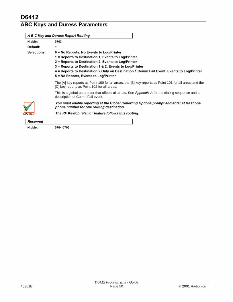
D6412ABC Keys and Duress Parameters
D6412 Program Entry Guide45351B Page 50 © 2001 Radionics
A B C Key and Duress Report Routing
Nibble: 0703
Default: 1
Selections: 0 = No Reports, No Events to Log/Printer1 = Reports to Destination 1, Events to Log/Printer2 = Reports to Destination 2, Events to Log/Printer3 = Reports to Destination 1 & 2, Events to Log/Printer4 = Reports to Destination 2 Only on Destination 1 Comm Fail Event, Events to Log/Printer5 = No Reports, Events to Log/Printer
The [A] key reports as Point 100 for all areas, the [B] key reports as Point 101 for all areas and the[C] key reports as Point 102 for all areas.
This is a global parameter that affects all areas. See Appendix A for the dialing sequence and adescription of Comm Fail event.
You must enable reporting at the Global Reporting Options prompt and enter at least onephone number for one routing destination.
The RF Keyfob “Panic” feature follows this routing.
Reserved
Nibble: 0704-0705
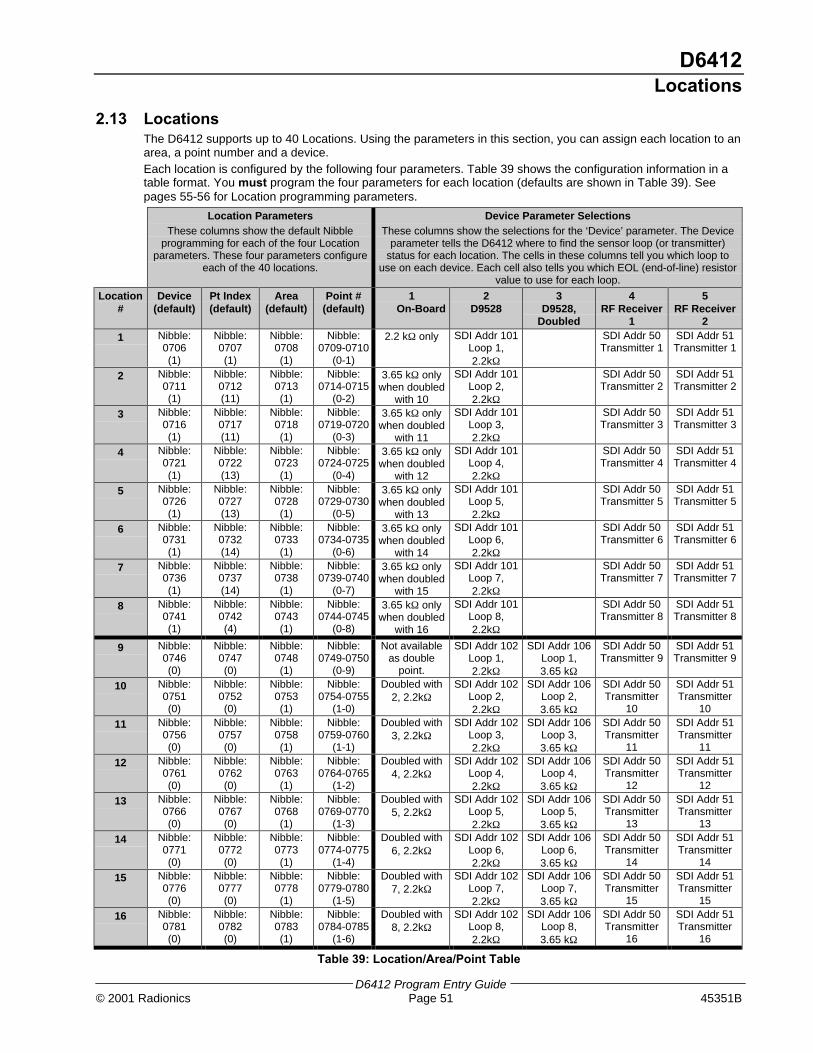
D6412Locations
D6412 Program Entry Guide© 2001 Radionics Page 51 45351B
2.13 LocationsThe D6412 supports up to 40 Locations. Using the parameters in this section, you can assign each location to anarea, a point number and a device.Each location is configured by the following four parameters. Table 39 shows the configuration information in atable format. You must program the four parameters for each location (defaults are shown in Table 39). Seepages 55-56 for Location programming parameters.
Location ParametersThese columns show the default Nibble
programming for each of the four Locationparameters. These four parameters configure
each of the 40 locations.
Device Parameter SelectionsThese columns show the selections for the ‘Device’ parameter. The Device
parameter tells the D6412 where to find the sensor loop (or transmitter)status for each location. The cells in these columns tell you which loop to
use on each device. Each cell also tells you which EOL (end-of-line) resistorvalue to use for each loop.
Location#
Device(default)
Pt Index(default)
Area(default)
Point #(default)
1On-Board
2D9528
3D9528,
Doubled
4RF Receiver
1
5RF Receiver
2
1 Nibble:0706(1)
Nibble:0707(1)
Nibble:0708(1)
Nibble:0709-0710
(0-1)
2.2 kΩ only SDI Addr 101Loop 1,2.2kΩ
SDI Addr 50Transmitter 1
SDI Addr 51Transmitter 1
2 Nibble:0711(1)
Nibble:0712(11)
Nibble:0713(1)
Nibble:0714-0715
(0-2)
3.65 kΩ onlywhen doubled
with 10
SDI Addr 101Loop 2,2.2kΩ
SDI Addr 50Transmitter 2
SDI Addr 51Transmitter 2
3 Nibble:0716(1)
Nibble:0717(11)
Nibble:0718(1)
Nibble:0719-0720
(0-3)
3.65 kΩ onlywhen doubled
with 11
SDI Addr 101Loop 3,2.2kΩ
SDI Addr 50Transmitter 3
SDI Addr 51Transmitter 3
4 Nibble:0721(1)
Nibble:0722(13)
Nibble:0723(1)
Nibble:0724-0725
(0-4)
3.65 kΩ onlywhen doubled
with 12
SDI Addr 101Loop 4,2.2kΩ
SDI Addr 50Transmitter 4
SDI Addr 51Transmitter 4
5 Nibble:0726(1)
Nibble:0727(13)
Nibble:0728(1)
Nibble:0729-0730
(0-5)
3.65 kΩ onlywhen doubled
with 13
SDI Addr 101Loop 5,2.2kΩ
SDI Addr 50Transmitter 5
SDI Addr 51Transmitter 5
6 Nibble:0731(1)
Nibble:0732(14)
Nibble:0733(1)
Nibble:0734-0735
(0-6)
3.65 kΩ onlywhen doubled
with 14
SDI Addr 101Loop 6,2.2kΩ
SDI Addr 50Transmitter 6
SDI Addr 51Transmitter 6
7 Nibble:0736(1)
Nibble:0737(14)
Nibble:0738(1)
Nibble:0739-0740
(0-7)
3.65 kΩ onlywhen doubled
with 15
SDI Addr 101Loop 7,2.2kΩ
SDI Addr 50Transmitter 7
SDI Addr 51Transmitter 7
8 Nibble:0741(1)
Nibble:0742(4)
Nibble:0743(1)
Nibble:0744-0745
(0-8)
3.65 kΩ onlywhen doubled
with 16
SDI Addr 101Loop 8,2.2kΩ
SDI Addr 50Transmitter 8
SDI Addr 51Transmitter 8
9 Nibble:0746(0)
Nibble:0747(0)
Nibble:0748(1)
Nibble:0749-0750
(0-9)
Not availableas double
point.
SDI Addr 102Loop 1,2.2kΩ
SDI Addr 106Loop 1,3.65 kΩ
SDI Addr 50Transmitter 9
SDI Addr 51Transmitter 9
10 Nibble:0751(0)
Nibble:0752(0)
Nibble:0753(1)
Nibble:0754-0755
(1-0)
Doubled with2, 2.2kΩ
SDI Addr 102Loop 2,2.2kΩ
SDI Addr 106Loop 2,3.65 kΩ
SDI Addr 50Transmitter
10
SDI Addr 51Transmitter
10
11 Nibble:0756(0)
Nibble:0757(0)
Nibble:0758(1)
Nibble:0759-0760
(1-1)
Doubled with3, 2.2kΩ
SDI Addr 102Loop 3,2.2kΩ
SDI Addr 106Loop 3,3.65 kΩ
SDI Addr 50Transmitter
11
SDI Addr 51Transmitter
11
12 Nibble:0761(0)
Nibble:0762(0)
Nibble:0763(1)
Nibble:0764-0765
(1-2)
Doubled with4, 2.2kΩ
SDI Addr 102Loop 4,2.2kΩ
SDI Addr 106Loop 4,3.65 kΩ
SDI Addr 50Transmitter
12
SDI Addr 51Transmitter
12
13 Nibble:0766(0)
Nibble:0767(0)
Nibble:0768(1)
Nibble:0769-0770
(1-3)
Doubled with5, 2.2kΩ
SDI Addr 102Loop 5,2.2kΩ
SDI Addr 106Loop 5,3.65 kΩ
SDI Addr 50Transmitter
13
SDI Addr 51Transmitter
13
14 Nibble:0771(0)
Nibble:0772(0)
Nibble:0773(1)
Nibble:0774-0775
(1-4)
Doubled with6, 2.2kΩ
SDI Addr 102Loop 6,2.2kΩ
SDI Addr 106Loop 6,3.65 kΩ
SDI Addr 50Transmitter
14
SDI Addr 51Transmitter
14
15 Nibble:0776(0)
Nibble:0777(0)
Nibble:0778(1)
Nibble:0779-0780
(1-5)
Doubled with7, 2.2kΩ
SDI Addr 102Loop 7,2.2kΩ
SDI Addr 106Loop 7,3.65 kΩ
SDI Addr 50Transmitter
15
SDI Addr 51Transmitter
15
16 Nibble:0781(0)
Nibble:0782(0)
Nibble:0783(1)
Nibble:0784-0785
(1-6)
Doubled with8, 2.2kΩ
SDI Addr 102Loop 8,2.2kΩ
SDI Addr 106Loop 8,3.65 kΩ
SDI Addr 50Transmitter
16
SDI Addr 51Transmitter
16
Table 39: Location/Area/Point Table

D6412Locations
D6412 Program Entry Guide45351B Page 52 © 2001 Radionics
Location ParametersThese columns show the default Nibble
programming for each of the four Locationparameters. These four parameters configure
each of the 40 locations.
Device Parameter SelectionsThese columns show the selections for the ‘Device’ parameter. The Device
parameter tells the D6412 where to find the sensor loop (or transmitter)status for each location. The cells in these columns tell you which loop to
use on each device. Each cell also tells you which EOL (end-of-line) resistorvalue to use for each loop.
Location#
Device(default)
Pt Index(default)
Area(default)
Point #(default)
1On-Board
2D9528
3D9528,
Doubled
4RF Receiver
1
5RF Receiver
2
17 Nibble:0786(0)
Nibble:0787(0)
Nibble:0788(1)
Nibble:0789-0790
(1-7)
SDI Addr 103Loop 1,2.2kΩ
SDI Addr 106Loop 1,2.2kΩ
SDI Addr 50Transmitter
17
SDI Addr 51Transmitter
17
18 Nibble:0791(0)
Nibble:0792(0)
Nibble:0793(1)
Nibble:0794-0795
(1-8)
SDI Addr 103Loop 2,2.2kΩ
SDI Addr 106Loop 2,2.2kΩ
SDI Addr 50Transmitter
18
SDI Addr 51Transmitter
18
19 Nibble:0796(0)
Nibble:0797(0)
Nibble:0798(1)
Nibble:0799-0800
(1-9)
SDI Addr 103Loop 3,2.2kΩ
SDI Addr 106Loop 3,2.2kΩ
SDI Addr 50Transmitter
19
SDI Addr 51Transmitter
19
20 Nibble:0801(0)
Nibble:0802(0)
Nibble:0803(1)
Nibble:0804-0805
(2-0)
SDI Addr 103Loop 4,2.2kΩ
SDI Addr 106Loop 4,2.2kΩ
SDI Addr 50Transmitter
20
SDI Addr 51Transmitter
20
21 Nibble:0806(0)
Nibble:0807(0)
Nibble:0808(1)
Nibble:0809-0810
(2-1)
SDI Addr 103Loop 5,2.2kΩ
SDI Addr 106Loop 5,2.2kΩ
SDI Addr 50Transmitter
21
SDI Addr 51Transmitter
21
22 Nibble:0811(0)
Nibble:0812(0)
Nibble:0813(1)
Nibble:0814-0815
(2-2)
SDI Addr 103Loop 6,2.2kΩ
SDI Addr 106Loop 6,2.2kΩ
SDI Addr 50Transmitter
22
SDI Addr 51Transmitter
22
23 Nibble:0816(0)
Nibble:0817(0)
Nibble:0818(1)
Nibble:0819-0820
(2-3)
SDI Addr 103Loop 7,2.2kΩ
SDI Addr 106Loop 7,2.2kΩ
SDI Addr 50Transmitter
23
SDI Addr 51Transmitter
23
24 Nibble:0821(0)
Nibble:0822(0)
Nibble:0823(1)
Nibble:0824-0825
(2-4)
SDI Addr 103Loop 8,2.2kΩ
SDI Addr 106Loop 8,2.2kΩ
SDI Addr 50Transmitter
24
SDI Addr 51Transmitter
24
25 Nibble:0826(0)
Nibble:0827(0)
Nibble:0828(1)
Nibble0829-0830
(2-5)
SDI Addr 104Loop 1,2.2kΩ
SDI Addr 107Loop 1,3.65kΩ
SDI Addr 50Transmitter
25
SDI Addr 51Transmitter
25
26 Nibble:0831(0)
Nibble:0832(0)
Nibble:0833(1)
Nibble0834-0835
(2-6)
SDI Addr 104Loop 2,2.2kΩ
SDI Addr 107Loop 2,3.65kΩ
SDI Addr 50Transmitter
26
SDI Addr 51Transmitter
26
27 Nibble:0836(0)
Nibble:0837(0)
Nibble:0838(1)
Nibble0839-0840
(2-7)
SDI Addr 104Loop 3,2.2kΩ
SDI Addr 107Loop 3,3.65kΩ
SDI Addr 50Transmitter
27
SDI Addr 51Transmitter
27
28 Nibble:0841(0)
Nibble:0842(0)
Nibble:0843(1)
Nibble0844-0845
(2-8)
SDI Addr 104Loop 4,2.2kΩ
SDI Addr 107Loop 4,3.65kΩ
SDI Addr 50Transmitter
28
SDI Addr 51Transmitter
28
29 Nibble:0846(0)
Nibble:0847(0)
Nibble:0848(1)
Nibble0849-0850
(2-9)
SDI Addr 104Loop 5,2.2kΩ
SDI Addr 107Loop 5,3.65kΩ
SDI Addr 50Transmitter
29
SDI Addr 51Transmitter
29
30 Nibble:0851(0)
Nibble:0852(0)
Nibble:0853(1)
Nibble0854-0855
(3-0)
SDI Addr 104Loop 6,2.2kΩ
SDI Addr 107Loop 6,3.65kΩ
SDI Addr 50Transmitter
30
SDI Addr 51Transmitter
30
31 Nibble:0856(0)
Nibble:0857(0)
Nibble:0858(1)
Nibble0859-0860
(3-1)
SDI Addr 104Loop 7,2.2kΩ
SDI Addr 107Loop 7,3.65kΩ
SDI Addr 50Transmitter
31
SDI Addr 51Transmitter
31
32 Nibble:0861(0)
Nibble:0862(0)
Nibble:0863(1)
Nibble0864-0865
(3-2)
SDI Addr 104Loop 8,2.2kΩ
SDI Addr 107Loop 8,3.65kΩ
SDI Addr 50Transmitter
32
SDI Addr 51Transmitter
32
Table 39 (Cont.): Location/Area/Point Table

D6412Locations
D6412 Program Entry Guide© 2001 Radionics Page 53 45351B
Location ParametersThese columns show the default Nibble
programming for each of the four Locationparameters. These four parameters configure
each of the 40 locations.
Device Parameter SelectionsThese columns show the selections for the ‘Device’ parameter. The Device
parameter tells the D6412 where to find the sensor loop (or transmitter)status for each location. The cells in these columns tell you which loop to
use on each device. Each cell also tells you which EOL (end-of-line) resistorvalue to use for each loop.
Location#
Device(default)
Pt Index(default)
Area(default)
Point #(default)
1On-Board
2D9528
3D9528,
Doubled
4RF Receiver
1
5RF Receiver
2
33 Nibble:0866(0)
Nibble:0867(0)
Nibble:0868(1)
Nibble0869-0870
(3-3)
SDI Addr 105Loop 1,2.2kΩ
SDI Addr 107Loop 1,2.2kΩ
SDI Addr 50Transmitter
33
SDI Addr 51Transmitter
33
34 Nibble:0871(0)
Nibble:0872(0)
Nibble:0873(1)
Nibble0874-0875
(3-4)
SDI Addr 105Loop 2,2.2kΩ
SDI Addr 107Loop 2,2.2kΩ
SDI Addr 50Transmitter
34
SDI Addr 51Transmitter
34
35 Nibble:0876(0)
Nibble:0877(0)
Nibble:0878(1)
Nibble0879-0880
(3-5)
SDI Addr 105Loop 3,2.2kΩ
SDI Addr 107Loop 3,2.2kΩ
SDI Addr 50Transmitter
35
SDI Addr 51Transmitter
35
36 Nibble:0881(0)
Nibble:0882(0)
Nibble:0883(1)
Nibble0884-885
(3-6)
SDI Addr 105Loop 4,2.2kΩ
SDI Addr 107Loop 4,2.2kΩ
SDI Addr 50Transmitter
36
SDI Addr 51Transmitter
36
37 Nibble:0886(0)
Nibble:0887(0)
Nibble:0888(1)
Nibble0889-0890
(3-7)
SDI Addr 105Loop 5,2.2kΩ
SDI Addr 107Loop 5,2.2kΩ
SDI Addr 50Transmitter
37
SDI Addr 51Transmitter
37
38 Nibble:0891(0)
Nibble:0892(0)
Nibble:0893(1)
Nibble0894-0895
(3-8)
SDI Addr 105Loop 6,2.2kΩ
SDI Addr 107Loop 6,2.2kΩ
SDI Addr 50Transmitter
38
SDI Addr 51Transmitter
38
39 Nibble:0896(0)
Nibble:0897(0)
Nibble:0898(1)
Nibble0899-0900
(3-9)
SDI Addr 105Loop 7,2.2kΩ
SDI Addr 107Loop 7,2.2kΩ
SDI Addr 50Transmitter
39
SDI Addr 51Transmitter
39
40 Nibble:0901(0)
Nibble:0902(0)
Nibble:0903(1)
Nibble0904-0905
(4-0)
SDI Addr 105Loop 8,2.2kΩ
SDI Addr 107Loop 8,2.2kΩ
SDI Addr 50Transmitter
40
SDI Addr 51Transmitter
40
Table 39 (Cont.): Location/Area/Point Table
Sample Location Scenario
The following scenario is intended to show how the parameters in Table 39 are used to configure aLocation by walking you through a step-by-step example.
Suppose the intended premises for the D6412 is a small store that consists of the following fourareas:
− Area 1: Manager’s Office/Money Room
− Area 2: Entrance Foyer
− Area 3: Sales Floor
− Area 4: Employee Break Room
Your task is set up Location 9 as an Entry/Exit door (door contact) for Area 2. It is connected to aD9528 Point Expansion Module. It is the first point in Area 2.
Step 1: Set the Device Parameter
The Device parameter tells the D6412 how the Location is connected to the panel: on-board sensorloop, off-board expander (D9528) or RF expander (SDI RF Receiver). Since Location 9 isconnected to a D9528 Point Expansion Module without point-doubling, you would enter a “2” inNibble 0746.
Location#
Device(default)
Pt Index(default)
Area(default)
Point #(default)
1On-Board
2D9528
3D9528,
Doubled
4RF Receiver
1
5RF Receiver
2
9 Nibble:0746
2
Nibble:0747(0)
Nibble:0748(1)
Nibble:0749-0750
(0-9)
Not availableas double
point.
SDI Addr 102Loop 1,2.2 kΩ
SDI Addr 106Loop 1,3.65 kΩ
SDI Addr 50Transmitter 9
SDI Addr 51Transmitter 9
Change Nibble 0746 from “0” to “2” for D9528 without point-doubling.

D6412Locations
D6412 Program Entry Guide45351B Page 54 © 2001 Radionics
Step 2: Set the Point Index Parameter
The Point Index tells the D6412 how the particular Location will “behave.” There are severalparameters for configuring a Point Index. See Point Index Configuration, page 57, for details.
For example, your entry for Nibble 0747 would be “11.” Based on the Point Index default, thismeans that the D6412 will now recognize the device at Location 9 as an Entry/Exit Delay 1 PointType. To learn more about the Point Index Configuration for this particular point type and otherpoint types, see page 57.
Location#
Device(default)
Pt Index(default)
Area(default)
Point #(default)
1On-Board
2D9528
3D9528,
Doubled
4RF Receiver
1
5RF Receiver
2
9 Nibble:0746
2
Nibble:074711
Nibble:0748(1)
Nibble:0749-0750
(0-9)
Not availableas double
point.
SDI Addr 102Loop 1,2.2 kΩ
SDI Addr 106Loop 1,3.65 kΩ
SDI Addr 50Transmitter 9
SDI Addr 51Transmitter 9
Change Nibble 0747 from “0” to “11” for Entry/Exit Delay 1 Point Type.
Step 3: Set the Area Parameter
The Area parameter tells the D6412 which area Location 9 will appear in. Each location can beassigned to only one area. Since Location 9 is in Area 2 for this example, enter a “2” in Nibble 0748to assign Location 9 to Area 2.
Location#
Device(default)
Pt Index(default)
Area(default)
Point #(default)
1On-Board
2D9528
3D9528,
Doubled
4RF Receiver
1
5RF Receiver
2
9 Nibble:0746
2
Nibble:074711
Nibble:0748
2
Nibble:0749-0750
(0-9)
Not availableas double
point.
SDI Addr 102Loop 1,2.2 kΩ
SDI Addr 106Loop 1,3.65 kΩ
SDI Addr 50Transmitter 9
SDI Addr 51Transmitter 9
Change Nibble 0748 from “1” to “2” to assign Location 9 to Area 2.
Step 4: Set the Point # Parameter
The Point Number determines the point number that appears on Command Center displays, in thepanel event log and at the optional printer for Location 9. This number is also reported to theCentral Station.
The default point number for Location 9 is “09” (Nibble 0749-0750). However, this default can bechanged to any number. Since this is the first location in a new area (Area 2), change the default to“01” by entering a “0” in Nibble 0749 and a “1” in Nibble 0750. Be careful not to duplicate pointnumbers within the same area.
Location#
Device(default)
Pt Index(default)
Area(default)
Point #(default)
1On-Board
2D9528
3D9528,
Doubled
4RF Receiver
1
5RF Receiver
2
9 Nibble:0746
2
Nibble:074711
Nibble:0748
2
Nibble:0749-0750
0-1
Not availableas double
point.
SDI Addr 102Loop 1,2.2 kΩ
SDI Addr 106Loop 1,3.65 kΩ
SDI Addr 50Transmitter 9
SDI Addr 51Transmitter 9
Change the Point Number from “09” to “01” for Location 9.
Make sure two Nibbles are used to enter the Point Number.
Summary
The D6412 will now recognize the following information for Location 9:
− Device: 2 (Location is on a D9528 Point Expansion Module)
− Point Index: 11 (Entry/Exit Delay 1)
− Area: 2 (Location 9 is assigned to Area 2)
− Point #: 01 (Location 9 point type will report to Command Centers, panel event log andCentral Station as Point # 01 in Area 2).

D6412Locations
D6412 Program Entry Guide© 2001 Radionics Page 55 45351B
Location ##, Device
Nibble: See Table 39
Default: See Table 39
Selections: 0 = Disabled1 = On-board2 = Wired Point Expander3 = Doubled Wired Point Expander4 = SDI RF Receiver 15 = SDI RF Receiver 2
Each Location in the D6412 can be assigned to one of three types for devices: the D6412’s on-board sensor loops, a D9528 point expander or a RF point expander. Use each location’s deviceparameter to assign the location to a device.
RF Transmitters and Point States
With the exception of the door/window transmitter, all RF transmitters show only two point states(Normal and Shorted).
When a location is assigned to a RF point expander, the door/window transmitter (RF3401)has the ability to monitor both a reed switch (magnet) and a supervised sensor loop. Afterthe ID for a door/window transmitter is added, the D6412 shows the status for the point asnormal. If the first message from the transmitter is “no magnet and open loop,” the D6412reports the point as faulted. If a “normal magnet” message is received, the magnet issupervised. If a “normal loop” message is received, the loop is supervised.
For this example, the door/window transmitter is mounted on a doorjamb and its magnet on thedoor. Closing the door places the magnet next to the reed switch. Now the panel has seen the reedswitch in a normal (not faulted) state. From this point forward, it will show the point (door/windowtransmitter) as faulted whenever it sees the reed switch faulted. It will show the point as normalwhen the reed switch returns to normal, even though the sensor loop remains faulted.
To continue with this example, we have attached a contact on a window near the door. We havewired in the contact and the EOL resistor to the Door/Window transmitter’s sensor loop and closedthe window. Now the panel has seen the sensor loop in a normal (not faulted) state. From this pointforward, it will show the point (door window transmitter) as faulted whenever it sees either thesensor loop or the reed switch faulted. It will only show the point as normal when both the reedswitch and the sensor loop return to normal.
When only the reed switch is monitored, only the Normal and Shorted point states are shown.
When both the reed switch and sensor loop are monitored, only the Normal and Shorted pointstates are shown.
When only the sensor loop is monitored, Normal, Shorted, and Open point states are shown.
Cut out reed switch if not used.
Location ##, Point Index
Nibble: See Table 39
Default: See Table 39
Selections: 0 – 15 (See Table 40)
The Point Index determines how the system responds to faults on the sensor loop assigned to thelocation. See Point Index Configuration, page 57, for a complete description of point indexes. ForWatch Point only functionality (no Trouble, no Alarm), set the Point Index to 0.

D6412Locations
D6412 Program Entry Guide45351B Page 56 © 2001 Radionics
Location ##, Area
Nibble: See Table 39
Default: See Table 39
Selections: 0 = Disabled
1 = Assign Location X to Area 12 = Assign Location X to Area 23 = Assign Location X to Area 34 = Assign Location X to Area 4
The Area assignment parameter determines which area a location is assigned to. Each locationcan only be assigned to one area.
Location ##, Point Number
Nibble: See Table 39
Default: See Table 39
Selections: 0 – 9 (Selection range represents Command Center keypad keys)
This parameter determines the Point Number that appears in command center displays, the panelevent log and at the optional printer. This is also the point number reported to the central station.
This parameter can be used to create a Point 1 for each area.

D6412Point Index Configuration
D6412 Program Entry Guide© 2001 Radionics Page 57 45351B
2.14 Point Index ConfigurationThe D6412 can monitor any combination of up to 40 sensor loops and/or RF transmitters. Each sensor loop ortransmitter is assigned to a location. Each location is assigned to one of 15 Point Indexes so that the D6412knows how to respond to sensor loop or transmitter changes.
Table 40 outlines the Point Index parameters and the Nibbles associated with them for each Point Index.
PointIndex
Point Type PulseCount
PulseCountTime
Options 1 Options 2
ReportEnableTrouble
Response
AlarmRoute
RestoralRoute
1 Nibble 0906(1)
Nibble 0907(0)
Nibble 0908(0)
Nibble 0909(0)
Nibble 0910(2)
Nibble 0911(11)
Nibble 0912(1)
Nibble 0913(1)
2 Nibble 0914(2)
Nibble 0915(0)
Nibble 0916(0)
Nibble 0917(0)
Nibble 0918(2)
Nibble 0919(11)
Nibble 0920(1)
Nibble 0921(1)
3 Nibble 0922(3)
Nibble 0923(0)
Nibble 0924(0)
Nibble 0925(1)
Nibble 0926(0)
Nibble 0927(10)
Nibble 0928(1)
Nibble 0929(1)
4 Nibble 0930(4)
Nibble 0931(0)
Nibble 0932(0)
Nibble 0933(1)
Nibble 0934(7)
Nibble 0935(9)
Nibble 0936(1)
Nibble 0937(1)
5 Nibble 0938(5)
Nibble 0939(0)
Nibble 0940(0)
Nibble 0941(1)
Nibble 0942(7)
Nibble 0943(9)
Nibble 0944(1)
Nibble 0945(1)
6 Nibble 0946(6)
Nibble 0947(0)
Nibble 0948(0)
Nibble 0949(1)
Nibble 0950(7)
Nibble 0951(9)
Nibble 0952(1)
Nibble 0953(1)
7 Nibble 0954(7)
Nibble 0955(0)
Nibble 0956(0)
Nibble 0957(1)
Nibble 0958(7)
Nibble 0959(9)
Nibble 0960(1)
Nibble 0961(1)
8 Nibble 0962(8)
Nibble 0963(0)
Nibble 0964(0)
Nibble 0965(1)
Nibble 0966(7)
Nibble 0967(9)
Nibble 0968(1)
Nibble 0969(1)
9 Nibble 0970(9)
Nibble 0971(0)
Nibble 0972(0)
Nibble 0973(0)
Nibble 0974(0)
Nibble 0975(9)
Nibble 0976(1)
Nibble 0977(1)
10 Nibble 0978(10)
Nibble 0979(0)
Nibble 0980(0)
Nibble 0981(8)
Nibble 0982(2)
Nibble 0983(11)
Nibble 0984(1)
Nibble 0985(1)
11 Nibble 0986(11)
Nibble 0987(0)
Nibble 0988(0)
Nibble 0989(5)
Nibble 0990(7)
Nibble 0991(9)
Nibble 0992(1)
Nibble 0993(1)
12 Nibble 0994(12)
Nibble 0995(0)
Nibble 0996(0)
Nibble 0997(5)
Nibble 0998(7)
Nibble 0999(9)
Nibble 1000(1)
Nibble 1001(1)
13 Nibble 1002(13)
Nibble 1003(0)
Nibble 1004(0)
Nibble 1005(1)
Nibble 1006(7)
Nibble 1007(9)
Nibble 1008(1)
Nibble 1009(1)
14 Nibble 1010(14)
Nibble 1011(0)
Nibble 1012(0)
Nibble 1013(1)
Nibble 1014(7)
Nibble 1015(9)
Nibble 1016(1)
Nibble 1017(1)
15 Nibble 1018(14)
Nibble 1019(0)
Nibble 1020(0)
Nibble 1021(5)
Nibble 1022(7)
Nibble 1023(9)
Nibble 1024(1)
Nibble 1025(1)
Table 40: Point Index Configuration Table
Point Type, Point Index
Nibble: See Table 40
Default: See Table 40
Selections: 0-15 (See Table 41)
This parameter defines what type of point each point index is associated with. See Table 41 for adescription of each type of point and the events and reports associated with that point type.
• Controlled Point: Controlled points are turned on and off when the user turns the system on(armed) and off (disarmed).
• 24-hour Point: 24-hour points are always on and cannot be turned off by the user. Faults on 24-hour points do not have to be cleared or bypassed to turn the system on (armed).

D6412Point Index Configuration
D6412 Program Entry Guide45351B Page 58 © 2001 Radionics
Point Type Description Events/Reports [Reference to Appendix B]
0 Watch ModeOnly
No alarm or trouble response to opens or shorts (WatchMode Only).
1 24-hour,Fire
Short on sensor loop starts Fire Alarm response.
Open on sensor loop starts trouble response.
Activates Fire Alarm Output (Temporal Code 3).
Do not assign ‘doubled locations (points)’ to a FirePoint Index.
Fire Alarm [75-77], Fire Missing [78], FireRestore from Alarm [79], Fire Restore fromMissing [174], Fire Trouble [80], Fire TroubleRestore [81], Fire Bypass [26-27], SwingerBypass [33], Restoral from Swinger Bypass[173], Fire Unbypass [34]
2 24-hour,Fire withAlarmVerification
Short on sensor loop starts the verification process:
1. Panel removes power to Point 1 (and activates FireVerification output function if programmed) for 15seconds to reset smoke detectors. See page 75 forFire Verification Output Function information.
2. Short on sensor loop within 120 seconds of resetstarts alarm response. If point remains normal oropen for the 120 second verification window thereis no alarm response.
Open on sensor loop starts trouble response.
Activates Fire Alarm Output (Temporal Code 3).
Do not assign ‘doubled locations (points)’ to a FirePoint Index.
Fire Alarm [75-77], Fire Missing [78], FireRestore from Alarm [79] , Fire Restore fromMissing [174], Fire Trouble [80], Fire TroubleRestore [81], Fire Bypass [26-27], FireUnbypass [34]
3 24-hour,Voice Active
The Voice Verification Module (D169) shorts a VoiceActive point to tell the panel a 2-way Voice Verificationsession is active. Only trouble on open option isavailable. See Voice Verification, Option 1, page 61, fora complete description of the Voice Verification function.
Trouble [139], Trouble Restore [146]
4 24-hour,Tamper
Short or open causes alarm response if no TroubleOption.
Alarm [3], Cross Alarm [10], Unverified Cross[17], Bypass [30-31], Swinger Bypass [33],Unbypass [36], Swinger Bypass Restore [173],Trouble [139], Trouble Restore [146], MissingTrouble [88], Restore from Alarm [112], Restorefrom Missing Trouble [176]
5 24-hour,Emergency
Short or open causes alarm response if no TroubleOption.
Alarm [4], Cross Alarm [11], Unverified Cross[17], Bypass [30-31], Swinger Bypass [33],Unbypass [36], Swinger Bypass Restore [173],Trouble [140], Trouble Restore [147], MissingTrouble [88], Restore from Alarm [113], Restorefrom Missing Trouble [176]
6 24-hour,Visible Panic
Short or open causes alarm response if no TroubleOption.
Alarm [5], Cross Alarm [12], Unverified Cross[17], Bypass [30-31], Swinger Bypass [33],Unbypass [36], Swinger Bypass Restore [173],Trouble [141], Trouble Restore [148], MissingTrouble [88], Restore from Alarm [114], Restorefrom Missing Trouble [176] reports.
7 24-hour,InvisiblePanic
Short or open causes alarm response if no TroubleOption.
No alarm tones or alarm display at Command Centereven if the Alarm Output option is enabled.
Alarm [6], Cross Alarm [13], Unverified Cross[17], Bypass [30-31], Swinger Bypass [33],Unbypass [36], Swinger Bypass Restore [173],Trouble [142], Trouble Restore [149], MissingTrouble [88], Restore from Alarm [115], Restorefrom Missing Trouble [176]
24-h
ou
r P
oin
t T
ypes
8 24-hour,Burglary
Short or open causes alarm response if no TroubleOption. Trouble option generates alarm response whenArea is All or Part On, Trouble response when area isOff.
Burglary [7], Cross Alarm [14], Unverified Cross[17], Bypass [30-31], Swinger Bypass [33],Unbypass [36], Swinger Bypass Restore [173],Trouble [143], Trouble Restore [150], MissingAlarm [87], Missing Trouble [88], Restore fromAlarm [116], Restore from Missing Alarm [175],Restore from Missing Trouble [176]
Table 41: Point Type Options
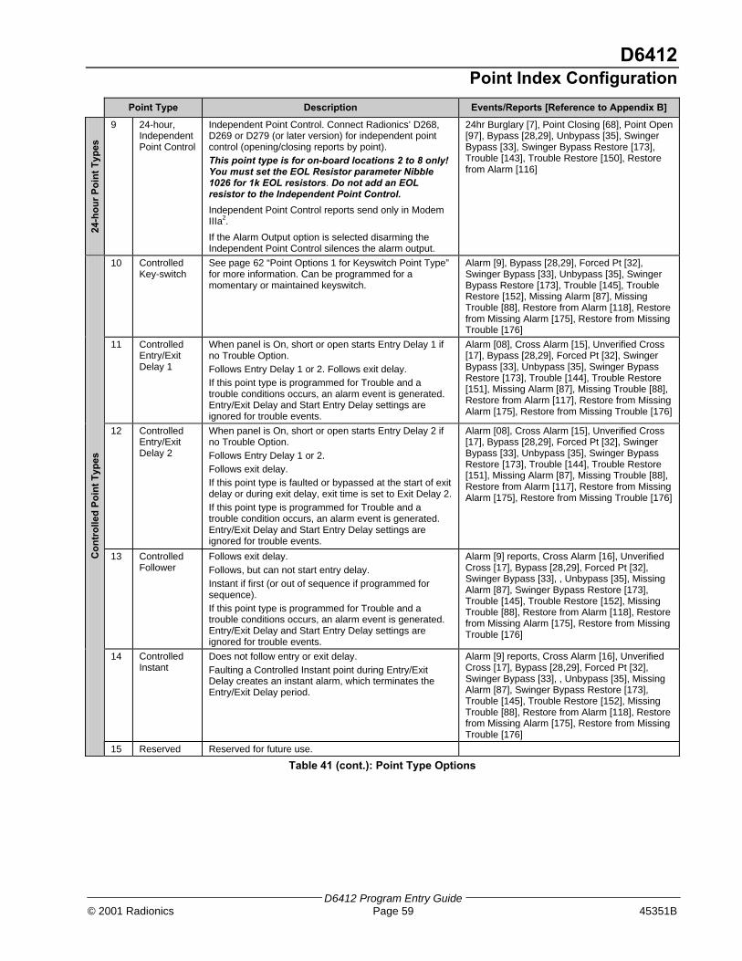
D6412Point Index Configuration
D6412 Program Entry Guide© 2001 Radionics Page 59 45351B
Point Type Description Events/Reports [Reference to Appendix B]24
-ho
ur
Po
int
Typ
es
9 24-hour,IndependentPoint Control
Independent Point Control. Connect Radionics’ D268,D269 or D279 (or later version) for independent pointcontrol (opening/closing reports by point).
This point type is for on-board locations 2 to 8 only!You must set the EOL Resistor parameter Nibble1026 for 1k EOL resistors. Do not add an EOLresistor to the Independent Point Control.
Independent Point Control reports send only in ModemIIIa2.
If the Alarm Output option is selected disarming theIndependent Point Control silences the alarm output.
24hr Burglary [7], Point Closing [68], Point Open[97], Bypass [28,29], Unbypass [35], SwingerBypass [33], Swinger Bypass Restore [173],Trouble [143], Trouble Restore [150], Restorefrom Alarm [116]
10 ControlledKey-switch
See page 62 “Point Options 1 for Keyswitch Point Type”for more information. Can be programmed for amomentary or maintained keyswitch.
Alarm [9], Bypass [28,29], Forced Pt [32],Swinger Bypass [33], Unbypass [35], SwingerBypass Restore [173], Trouble [145], TroubleRestore [152], Missing Alarm [87], MissingTrouble [88], Restore from Alarm [118], Restorefrom Missing Alarm [175], Restore from MissingTrouble [176]
11 ControlledEntry/ExitDelay 1
When panel is On, short or open starts Entry Delay 1 ifno Trouble Option.
Follows Entry Delay 1 or 2. Follows exit delay.
If this point type is programmed for Trouble and atrouble conditions occurs, an alarm event is generated.Entry/Exit Delay and Start Entry Delay settings areignored for trouble events.
Alarm [08], Cross Alarm [15], Unverified Cross[17], Bypass [28,29], Forced Pt [32], SwingerBypass [33], Unbypass [35], Swinger BypassRestore [173], Trouble [144], Trouble Restore[151], Missing Alarm [87], Missing Trouble [88],Restore from Alarm [117], Restore from MissingAlarm [175], Restore from Missing Trouble [176]
12 ControlledEntry/ExitDelay 2
When panel is On, short or open starts Entry Delay 2 ifno Trouble Option.
Follows Entry Delay 1 or 2.
Follows exit delay.
If this point type is faulted or bypassed at the start of exitdelay or during exit delay, exit time is set to Exit Delay 2.
If this point type is programmed for Trouble and atrouble condition occurs, an alarm event is generated.Entry/Exit Delay and Start Entry Delay settings areignored for trouble events.
Alarm [08], Cross Alarm [15], Unverified Cross[17], Bypass [28,29], Forced Pt [32], SwingerBypass [33], Unbypass [35], Swinger BypassRestore [173], Trouble [144], Trouble Restore[151], Missing Alarm [87], Missing Trouble [88],Restore from Alarm [117], Restore from MissingAlarm [175], Restore from Missing Trouble [176]
13 ControlledFollower
Follows exit delay.
Follows, but can not start entry delay.
Instant if first (or out of sequence if programmed forsequence).
If this point type is programmed for Trouble and atrouble conditions occurs, an alarm event is generated.Entry/Exit Delay and Start Entry Delay settings areignored for trouble events.
Alarm [9] reports, Cross Alarm [16], UnverifiedCross [17], Bypass [28,29], Forced Pt [32],Swinger Bypass [33], , Unbypass [35], MissingAlarm [87], Swinger Bypass Restore [173],Trouble [145], Trouble Restore [152], MissingTrouble [88], Restore from Alarm [118], Restorefrom Missing Alarm [175], Restore from MissingTrouble [176]
14 ControlledInstant
Does not follow entry or exit delay.
Faulting a Controlled Instant point during Entry/ExitDelay creates an instant alarm, which terminates theEntry/Exit Delay period.
Alarm [9] reports, Cross Alarm [16], UnverifiedCross [17], Bypass [28,29], Forced Pt [32],Swinger Bypass [33], , Unbypass [35], MissingAlarm [87], Swinger Bypass Restore [173],Trouble [145], Trouble Restore [152], MissingTrouble [88], Restore from Alarm [118], Restorefrom Missing Alarm [175], Restore from MissingTrouble [176]
Co
ntr
olle
d P
oin
t T
ypes
15 Reserved Reserved for future use.
Table 41 (cont.): Point Type Options

D6412Point Index Configuration
D6412 Program Entry Guide45351B Page 60 © 2001 Radionics
Pulse Count, Point Index ##
Nibble: See Table 40
Default: 0 for all Point Indexes, see Table 40Selections: 0 : 300 ms
1:20 ms2-15: number of pulses required within the programmed Pulse Count Time for an alarm to occur.
This parameter determines the number of times a sensor loop must pulse (electrically off normal) inthe Pulse Count Time (see below) before the panel declares the point faulted. This applies to bothon- and off-board points.
• Setting the Pulse Count to 0 tells the D6412 to look for 1 pulse within a 300 ms time-span beforedeclaring the point faulted).
• Setting the Pulse Count to 1 tells the D6412 to look for 1 pulse within a 20 ms time-span beforedeclaring the point faulted).
Radionics recommends leaving Pulse Count at the default of 0.
Pulse Count Time, Point Index ##
Nibble: See Table 40
Default: 0 for all Point Indexes, see Table 40Selections: 0-15 (See Table 42)
When the panel detects a pulse (electrically off normal), it starts a timer and waits the time selectedin this parameter to reach the Pulse Count and declare the point faulted.
If a single pulse starts the pulse count timer and lasts 20 seconds, the panel declares thepoint faulted regardless of the pulse count.
Pulse Count Time Selectionsfor 20 mS Point Scan Time
(On-board Points Only)
Pulse Count Time Selectionsfor 300 mS Point Scan Time(On- and Off-board Points)
Selection Pulse Count Time Selection Pulse Count Time0 0.5 Seconds 8 20 Seconds
1 1 Second 9 30 Seconds
2 2 Seconds 10 40 Seconds
3 3 Seconds 11 50 Seconds
4 4 Seconds 12 60 Seconds
5 5 Seconds 13 90 Seconds
6 10 Seconds 14 120 Seconds
7 15 Seconds 15 200 Seconds
Table 42: Pulse Count Time Selections
Off-board Points: only selections 8 to 15 are appropriate for off-board points. The Point ScanTime is fixed by the point expansion devices. Only assign off-board points to point indexes with thePulse Count Time programmed with selections 8 to 15.
Point Count/Point Count Time Example:
Suppose you must program a Point Index to detect four 20 ms pulses within 10 seconds before itdeclares the point off normal. Follow these steps:
1. Enter “4” in the Pulse Count Nibble of the Point Index you are configuring.. “4” identifies thenumber of pulses the D6412 must see.
2. Since your time span is 10 seconds, this Point Index will use a point scan time of 20 ms and isonly for on-board points (see left side of Table 43). The selection for 10 seconds is 6. Enter “6”into the Pulse Count Time Nibble of the Point Index you are configuring.

D6412Point Index Configuration
D6412 Program Entry Guide© 2001 Radionics Page 61 45351B
Options 1, Point Index ##
Nibble: See Table 40
Default: See Table 40
Selections: 0-15 (See Table 43)
Enter This Value to Select Options
Options 1, Point Index 0 1 2 3 4 5 6 7 8 9 10 11 12 13 14 15
No Options Enabled X
Enable Alarm Event Abort X X X X X X X X
Voice Verification X X X X X X X X
Armed for Part Mode X X X X X X X X
Sensor Trouble Monitor X X X X X X X X
Table 43: Point Index Options 1 Selections
• Alarm Event Abort (Non-Fire Points Only): assigns the abort feature to a Point Index. SeeAlarm Event Abort Window , page 69, to learn how to set the Alarm Event Abort Window.If a user acknowledges a non-fire alarm point event by entering their passcode before the AlarmEvent Abort Window expires:
− the alarm event is aborted. Alarm, Cancel* and Restoral reports associated with the alarmare not transmitted and the event becomes a local only event.
− the users hears a unique three long beep tone at the command center.
− the text command centers indicate that the alarm was aborted on the display. It appearsas a slow flash in Alarm Memory at LED command centers.
Alarm Event Abort is required for the SIA Control Panel Standard for False AlarmReduction.
* A Cancel window starts with the initiation of the alarm event and follows the Bell Time. If the useracknowledges the alarm inside the Cancel window (bell time), a Cancel [38] or a Fire Cancel [39]report is sent. If the Abort feature is enabled, the Cancel report is sent if the user acknowledges thealarm after the Abort window has expired, but before the bell time expires.
The Cancel Window is required for SIA Control Panel Standard for False AlarmReduction.
This option has no effect on Fire and Fire with Verification point types.
The Alarm Event Abort feature does not apply to alarm events initiated by the ABCKeys, the Duress passcode or the keyfob Panic function.
• Voice Verification: allows the panel to control a D169 2-way Voice Verification Module. TheD169 allows the central station personnel to verify alarms with a two-way voice session with thepremises. The premises phone line runs from the panel to the D169 and then to the premisesphones. There are two other module connections to the panel: the programmable relay output (-12 VDC) programmed with the Voice Request output function, and a point (zone) programmedas a Voice Active point. The panel must also have one or more points with the Voice Verificationoption selected.When a point with Voice Verification generates an alarm event:
1. The panel transmits the alarm report to the receiver at the central station.
2. When the central station receiver acknowledges the report, the panel activates the VoiceRequest output function and starts a 30-second report delay time. All reports are delayed.The D169 has 30 seconds to start a two-way voice session.
3. An operator at the central station picks up the phone line from the receiver with a DTMFtelephone and presses [2].

D6412Point Index Configuration
D6412 Program Entry Guide45351B Page 62 © 2001 Radionics
4. At the premises, the D169 picked up the phone line when the panel activated the VoiceRequest output function. When it hears the DTMF tone from the operator pressing [2], itbegins a two-way voice session by first shorting the panel’s Voice Active point.
5. When the Voice Active point is shorted, the panel silences the non-fire alarm output (setsthe Bell Timer to zero). Only the user can silence a fire alarm output.
6. As long as the Voice Active point is shorted, the panel continues to keep reports buffered.
7. The D169 ends the voice session by removing the short from the voice active point. Thepanel resets the bell time and Alarm Event Abort Window (assuming a user at thepremises did not change the arming state of the panel during the voice session). Normalreporting (communication) resumes.
• Armed for Part Mode: determines the points that arm when the user turns the system Part On.Only those points assigned to a point index (controlled point types only) with this option enabledare armed.
• Sensor Trouble Monitor: enables/disables reporting the sensor trouble monitor fault condition.This feature does not apply to fire point types or non-fire 24-hour point types. See SensorMonitor Time (page 68) for a complete description of the Sensor Trouble Monitor feature.
Point Options 1 for Keyswitch Point Type
Default: See Table 40
Selections: 0 = Maintained, All On, Off from Any1 = Maintained, All On, No Off2 = Maintained, No On, Off from Any4 = Maintained, Part On, Off from Any5 = Maintained, Part On, No Off6 = Maintained, No On, Off from Part On or Part 2 On8 = Momentary, All On, Off from Any9 = Momentary, All On, No Off10 = Momentary, No On, Off from Any12 = Momentary, Part On, Off from Any13 = Momentary, Part On, No Off14 = Momentary, No On, Off from Part On or Part 2 On
Keyswitch Operation
For maintained keyswitches, the EOL resistor for the point is connected in series. An open on thecircuit arms the area; a return to normal on the circuit disarms the area. A short on the circuitproduces an alarm if the area is armed and a trouble if the area is disarmed.
For momentary keyswitches, the EOL resistor for the point is connected in parallel with thekeyswitch so that the switch shorts the resistor when it operates. Operating the keyswitch (normalto short to normal) toggles the arming state. An open on the circuit produces an alarm if the area isarmed and a trouble if the area is disarmed.
See the D6412 Installation Guide (P/N: 45349) for detailed instructions on wiring a keyswitch.
Silencing Alarms
• Momentary Keyswitch: To silence alarms (stop Alarm output), operate the keyswitch. If thearea is armed, operating the keyswitch to silence the alarm will also disarm the area. If the areais disarmed, operating a momentary keyswitch to silence the alarm will not arm the area.
• Maintained Keyswitch: If the area is armed, turn the keyswitch to the disarmed position. TheD6412 will disarm the area and silence the alarm. If the area is disarmed, turn the keyswitch tothe armed position (the D6412 will not arm) and then return to the disarmed position.
Keyswitch Point Type Selections 3, 7, 11and 15 are reserved for future use.

D6412Point Index Configuration
D6412 Program Entry Guide© 2001 Radionics Page 63 45351B
Options 2, Point Index ##
Nibble: See Table 40
Default: See Table 40
Selections: 0-15 (See Table 44)
Enter This Value to Select Options
Option 0 1 2 3 4 5 6 7 8 9 10 11 12 13 14 15
No Options Enabled X
Swinger Bypass X X X X X X X X
Alarm Output X X X X X X X X
Can Be Bypassed or Force Armed X X X X X X X X
Cross Point X X X X X X X X
Table 44: Point Index Options 2 Selections
• Swinger Bypass: activates both Swinger Bypass functions for Alarm Output (Functions 1-5, 1-8to 1-12) and Point Reporting. See Swinger Count for Point Reports (Alarm, Trouble, Restore) onpage 68 for additional Swinger information.
Swinger Bypass is required for SIA Control Panel Standard for False Alarm Reduction.
• Alarm Output: activates the alarm output functions (Output Function 1-8 to 1-12, see Outputs,page 73) for alarm events.
• Can Be Bypassed or Force Armed: only points assigned to a point index with this optionenabled can be bypassed or force armed. Bypassed controlled points remain bypassed for thearming cycle. Force armed points return to the system automatically if they restore during thearming cycle.24-hour points (fire and non-fire) can be made bypassable with this option. They cannot be madeto force arm since they are always armed.
Force Arming is not permitted for UL applications.
• Cross Point: creates a Cross Point point index, which fixes the Point Pulse Count at two (2) anduses it and the Point Pulse Count Time as follows:
− When any point assigned to the Cross Point index detects a pulse, the D6412 starts thePulse Count Time as programmed in the Pulse Count Time parameter.
− If a second point assigned to the same Cross Point index detects a pulse, the D6412creates a Cross Point Alarm event for both points.
− A second pulse on the first point does not create an alarm event.
− If a single pulse on a cross point lasts 20 seconds, the D6412 creates an alarm event forthat point only; it is not a Cross Point event.
− If programmed for unverified event reporting (see Point Response Options, page 66), theD6412 sends an Unverified Cross [17] or a Fire Unverified [77] report point that detects apulse without another cross point pulse to verify it.
Cross Point is required for SIA Control Panel Standard for False Alarm Reduction.

D6412Point Index Configuration
D6412 Program Entry Guide45351B Page 64 © 2001 Radionics
RF Transmitters and Point States: with the exception of the door/window transmitter, all RFtransmitters show only two point states (Normal and Shorted).
When a location is assigned to a RF point expander, the door/window transmitter (RF3401)has the ability to monitor both a reed switch (magnet) and a supervised sensor loop. Afterthe ID for a door/window transmitter is added, the D6412 shows the status for the point asnormal. If the first message from the transmitter is “no magnet and open loop,” the D6412reports the point as faulted. If a “normal magnet” message is received, the magnet issupervised. If a “normal loop” message is received, the loop is supervised.Example: After the door/window transmitter ID is added, the panel shows the status for the pointas normal even though both the reed switch and sensor loop are faulted.For this example the door/window transmitter is mounted on a door jamb and its magnet on thedoor. Closing the door places the magnet next to the reed switch, now the panel has seen the reedswitch in a normal (not faulted) state. From this point forward, it will show the point (door windowtransmitter) as faulted whenever it sees the reed switch faulted. It will show the point as normalwhen the reed switch returns to normal, even though the sensor loop remains faulted.To continue with this example, we have attached a contact on a window near the door, We havewired in the contact and the EOL resistor to the Door/Window transmitter’s sensor loop and closedthe window. Now the panel has seen the sensor loop in a normal (not faulted) state. From this pointforward, it will show the point (door window transmitter) as faulted whenever it sees either thesensor loop or the reed switch faulted. It will only show the point as normal when both the reedswitch and the sensor loop return to normal.When the reed switch only is monitored only the Normal and Shorted point states are shown.When both the reed switch and sensor loop are monitored only the Normal and Shorted pointstates are shown.When the sensor loop only is monitored Normal, Shorted, and Open point states are shown.
Cut out reed switch if not used.
Reporting Enable, Trouble Response Options, Point Index ##
Nibble: See Table 40
Default: See Table 40Selections: 0-15 (See Table 45)
Enter This Value to Select Options
Option 0 1 2 3 4 5 6 7 8 9 10 11 12 13 14 15
No Alarm or Trouble Reports X
Alarm and Trouble Reports Enabled X X X X X X X X
Trouble Response on Open X X X X X X X X
Trouble Response on Short X X X X X X X X
Restoral Reports Enabled X X X X X X X X
Table 45: Reporting & Trouble Response Options
The trouble response for controlled and 24-hour burglary point types occurs only when the pointsare disarmed. When armed, any point fault generates an alarm response.Other 24-hour point types (Tamper, Emergency, Panic, Invisible, and Independent Point Control)always have trouble response as programmed.
Fire point types always have Trouble Response on Open and Alarm Response on Shortregardless of programming.
• Alarm and Trouble Reports Enabled: if enabled, the system generates Alarm and Troublereports.
• Trouble Response on Open: if enabled, an open circuit generates a Trouble response.
• Trouble Response on Short: if enabled, a shorted circuit generates a Trouble response.
• Restoral Reports Enabled: if enabled, the system generates Restoral reports.

D6412Point Index Configuration
D6412 Program Entry Guide© 2001 Radionics Page 65 45351B
Alarm Report Routing, Point Index ##
Nibble: See Table 40
Default: See Table 40
Selections: 0 = No Reports, No Events to Log/Printer1 = Reports to Destination 1, Events to Log/Printer2 = Reports to Destination 2, Events to Log/Printer3 = Reports to Destinations 1 & 2, Events to Log/Printer4 = Reports to Destination 2 Only On Destination 1 Comm Fail Event, Events to Log/Printer5 = No Reports, Events to Log/Printer
Reports for Alarm, Cancel and Exit Error events follow Alarm report routing. See Appendix A fordialing sequence and a description of Comm Fail event.
Restoral reports are routed as shown in the next parameter. Trouble reports are routed globally.See Global Reporting Options, page 15.
To enable reporting at the Global Reporting Options prompt, at least one phone numbermust be entered for one routing destination.
Restoral Reporting, Point Index ##
Nibble: See Table 40
Default: See Table 40
Selections: 0 = No Reports, No Events to Log/Printer1 = Reports to Destination 1, Events to Log/Printer2 = Reports to Destination 2, Events to Log/Printer3 = Reports to Destinations 1 & 2, Events to Log/Printer4 = Reports to Destination 2 Only On Destination 1 Comm Fail Event, Events to Log/Printer5 = No Reports, Events to Log/Printer
In Modem IIIa² format, the panel sends Restoral from Alarm, Restoral from Fire Alarm, etc. SeeAppendix A for dialing sequence and a description of Comm Fail event.
Alarm reports are routed as shown in the previous parameter. Trouble reports are routed globally.See Global Reporting Options, page 15.
To enable reporting at the Global Reporting Options prompt, at least one phone numbermust be entered for one routing destination.
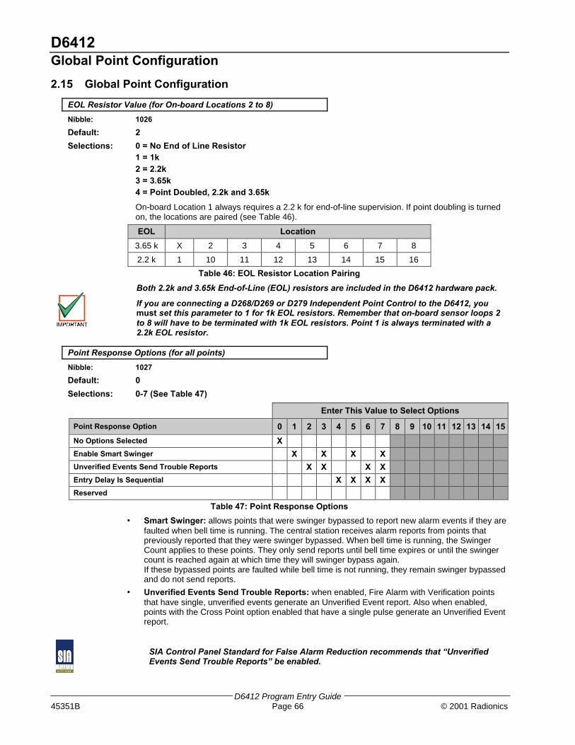
D6412Global Point Configuration
D6412 Program Entry Guide45351B Page 66 © 2001 Radionics
2.15 Global Point Configuration
EOL Resistor Value (for On-board Locations 2 to 8)
Nibble: 1026
Default: 2
Selections: 0 = No End of Line Resistor1 = 1k2 = 2.2k3 = 3.65k4 = Point Doubled, 2.2k and 3.65k
On-board Location 1 always requires a 2.2 k for end-of-line supervision. If point doubling is turnedon, the locations are paired (see Table 46).
EOL Location
3.65 k X 2 3 4 5 6 7 8
2.2 k 1 10 11 12 13 14 15 16
Table 46: EOL Resistor Location Pairing
Both 2.2k and 3.65k End-of-Line (EOL) resistors are included in the D6412 hardware pack.
If you are connecting a D268/D269 or D279 Independent Point Control to the D6412, youmust set this parameter to 1 for 1k EOL resistors. Remember that on-board sensor loops 2to 8 will have to be terminated with 1k EOL resistors. Point 1 is always terminated with a2.2k EOL resistor.
Point Response Options (for all points)
Nibble: 1027
Default: 0
Selections: 0-7 (See Table 47)
Enter This Value to Select Options
Point Response Option 0 1 2 3 4 5 6 7 8 9 10 11 12 13 14 15
No Options Selected X
Enable Smart Swinger X X X X
Unverified Events Send Trouble Reports X X X X
Entry Delay Is Sequential X X X X
Reserved
Table 47: Point Response Options
• Smart Swinger: allows points that were swinger bypassed to report new alarm events if they arefaulted when bell time is running. The central station receives alarm reports from points thatpreviously reported that they were swinger bypassed. When bell time is running, the SwingerCount applies to these points. They only send reports until bell time expires or until the swingercount is reached again at which time they will swinger bypass again.If these bypassed points are faulted while bell time is not running, they remain swinger bypassedand do not send reports.
• Unverified Events Send Trouble Reports: when enabled, Fire Alarm with Verification pointsthat have single, unverified events generate an Unverified Event report. Also when enabled,points with the Cross Point option enabled that have a single pulse generate an Unverified Eventreport.
SIA Control Panel Standard for False Alarm Reduction recommends that “UnverifiedEvents Send Trouble Reports” be enabled.

D6412Global Point Configuration
D6412 Program Entry Guide© 2001 Radionics Page 67 45351B
• Entry Delay Is Sequential: when enabled, the delay points must be faulted in order by location(lowest to highest). If the sequence is broken, entry delay is ended and an alarm responsebegins. Entry delay sequence starts when the location with an Entry/Exit delay point type isfaulted and continues with the faulting of consecutive locations assigned to Follower point types.The sequence of point types must be consecutive and without any gaps. For example, Locationsequence 2, 3, 4, 5 with Location 2 as an Entry/Exit point type and Locations 3-5 as Followerpoint types is OK. A location sequence of 2, 3, 5 with Location 4 as a Fire point type is not a validsequence. See Table 41, Point Type Options, on page 58, for descriptions of Entry/Exit andFollower point types.
Bypass / Force Bypass Report Routing
Nibble: 1028
Default: 1
Selections: 0 = No Reports, No Events to Log/Printer1 = Reports to Destination 1, Events to Log/Printer2 = Reports to Destination 2, Events to Log/Printer3 = Reports to Destinations 1 & 2, Events to Log/Printer4 = Reports to Destination 2 Only On Destination 1 Comm Fail Event, Events to Log/Printer5 = No Reports, Events to Log/Printer
This parameter sets the routing for Bypass and Forced reports. See Appendix A for dialingsequence and a description of Comm Fail event.
Reporting at the Global Reporting Options prompt must be enabled and at least onephone number for one routing destination must be entered.
Swinger Count for Alarm Output
Nibble: 1029
Default: 1
Selections: 0 (Swinger Disabled)1 - 15
Each individual point has a swinger count for alarm output.
Swinger Bypass reports are not sent for Swinger Bypass for Alarm Output. Swinger Bypass reportshave their own swinger count (see Swinger Count for Point Reports, page 68). The Swinger Countis reset on both arming and disarming of the system, allowing the Swinger Bypass feature to workfor both controlled and 24-hour points. A trouble condition occurs after Swinger Bypass.
Example: Assume the Swinger Bypass option is enabled, the panel is armed, no points are inalarm and the Swinger Count for Alarm Output is set to 2. Points 1, 3 and 5 go into alarm. At theend of bell time, the Swinger Count for Alarm Output for Points 1,3 and 5 decrements from 2 to 1.Since the counter does not reach zero, no points are bypassed.
A second alarm event for any of those points bypasses that point.
When the Swinger Count is set to zero (0), points with Swinger Bypass enabled arebypassed on one activation.
Swinger Count for Alarm Output is required for SIA Control Panel Standard for FalseAlarm Reduction.

D6412Global Point Configuration
D6412 Program Entry Guide45351B Page 68 © 2001 Radionics
Swinger Count for Point Reports (Alarm, Trouble, Restore)
Nibble: 1030
Default: 1
Selections: 0 (Swinger Disabled)1 - 15
Swinger shut down for the dialer is a global function that affects all areas.
Swinger Bypass [33] reports are sent for swinger bypass of points.
The Swinger Count is reset on both arming and disarming, allowing the Swinger Bypass feature towork for both controlled and 24-hour points.
Example: Assume the Swinger Bypass option is enabled, the panel is armed and there are noalarms. When the point sends an Alarm or Trouble event to the dialer, the swinger count for pointreports is checked. If the counter is at zero, the point is swinger bypassed (Swinger Bypass [33]report is sent). If the counter is not at zero, the panel decrements the counter. If the counter thengoes to zero, the point is swinger bypassed (Swinger Bypass [33] report is sent).
Swinger Count for Point Reports is required for SIA Control Panel Standard for FalseAlarm Reduction.
Bypass, Swinger Bypass, Sensor Trouble Report Options
Nibble: 1031
Default: 3
Selections: 0-15 (See Table 48)
Enter This Value to Select Options
Bypass, Swinger Bypass, Sensor Trouble Report Option 0 1 2 3 4 5 6 7 8 9 10 11 12 13 14 15
No Options Selected X
Point Bypass and Swinger Bypass Reports Enabled X X X X X X X X
Bypass and Swinger Bypass Restoral Reports Enabled X X X X X X X X
Sensor Trouble Reports Enabled X X X X X X X X
Sensor Trouble Restoral Reports Enabled X X X X X X X X
Table 48: Bypass, Swinger Bypass & Sensor Trouble Report Options
Use this parameter to enable Point Bypass, Swinger Bypass and Sensor reports (and theirrespective restoral reports) are enabled. This is a global parameter that affects all areas.
Sensor Monitor Time
Nibble: 1032-1033
Default: 0,7
Selections: 0 - 9
This parameter determines the number of days (00 to 99) that the panel can function withoutsensor (point) activity (time accumulates only when the area is off/disarmed). This feature isassigned by Point Index in Point Options 1. This feature does not apply to fire point types or non-fire 24-hour point types, only controlled points. If there is no sensor activity after the entered timeperiod, a trouble report is sent. See Options 1, Point Index ##, page 61, to enable/disable thesensor trouble monitor fault condition.
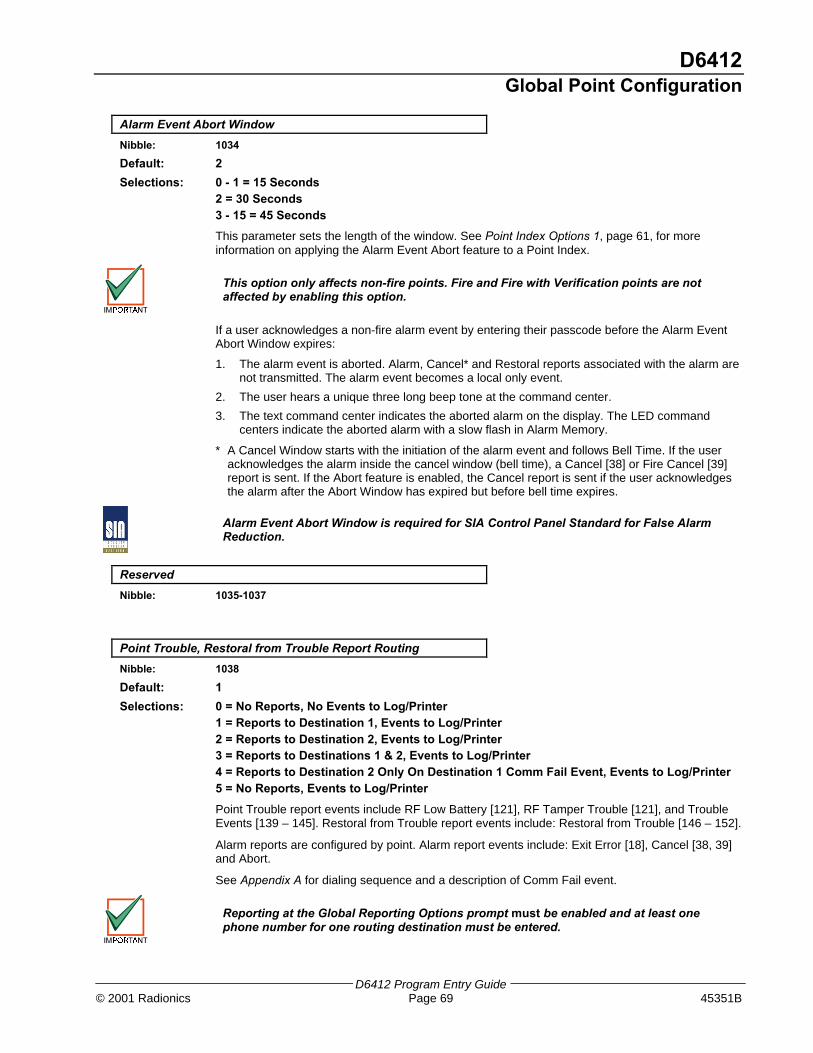
D6412Global Point Configuration
D6412 Program Entry Guide© 2001 Radionics Page 69 45351B
Alarm Event Abort Window
Nibble: 1034
Default: 2
Selections: 0 - 1 = 15 Seconds2 = 30 Seconds3 - 15 = 45 Seconds
This parameter sets the length of the window. See Point Index Options 1, page 61, for moreinformation on applying the Alarm Event Abort feature to a Point Index.
This option only affects non-fire points. Fire and Fire with Verification points are notaffected by enabling this option.
If a user acknowledges a non-fire alarm event by entering their passcode before the Alarm EventAbort Window expires:
1. The alarm event is aborted. Alarm, Cancel* and Restoral reports associated with the alarm arenot transmitted. The alarm event becomes a local only event.
2. The user hears a unique three long beep tone at the command center.
3. The text command center indicates the aborted alarm on the display. The LED commandcenters indicate the aborted alarm with a slow flash in Alarm Memory.
* A Cancel Window starts with the initiation of the alarm event and follows Bell Time. If the useracknowledges the alarm inside the cancel window (bell time), a Cancel [38] or Fire Cancel [39]report is sent. If the Abort feature is enabled, the Cancel report is sent if the user acknowledgesthe alarm after the Abort Window has expired but before bell time expires.
Alarm Event Abort Window is required for SIA Control Panel Standard for False AlarmReduction.
Reserved
Nibble: 1035-1037
Point Trouble, Restoral from Trouble Report Routing
Nibble: 1038
Default: 1
Selections: 0 = No Reports, No Events to Log/Printer1 = Reports to Destination 1, Events to Log/Printer2 = Reports to Destination 2, Events to Log/Printer3 = Reports to Destinations 1 & 2, Events to Log/Printer4 = Reports to Destination 2 Only On Destination 1 Comm Fail Event, Events to Log/Printer5 = No Reports, Events to Log/Printer
Point Trouble report events include RF Low Battery [121], RF Tamper Trouble [121], and TroubleEvents [139 – 145]. Restoral from Trouble report events include: Restoral from Trouble [146 – 152].
Alarm reports are configured by point. Alarm report events include: Exit Error [18], Cancel [38, 39]and Abort.
See Appendix A for dialing sequence and a description of Comm Fail event.
Reporting at the Global Reporting Options prompt must be enabled and at least onephone number for one routing destination must be entered.

D6412Global Output Configuration
D6412 Program Entry Guide45351B Page 70 © 2001 Radionics
2.16 Global Output ConfigurationThe D6412 supports a total of 20 programmable outputs including four on-board (PO1 to PO4) and up to 16 off-board.
Outputs 5 through 12 are on an off-board SDI device (D9529 OctoOutput or X7410i Module), SDI Address 150.
Outputs 13 through 20 are on an off-board SDI device (D9529 OctoOutput or X7410i Module), SDI Address 151.
Global Output Options
Nibble: 1039
Default: 0
Selections: 0-15 (See Table 49)
Enter This Value to Select Options
Global Output Option 0 1 2 3 4 5 6 7 8 9 10 11 12 13 14 15
No Options Selected X
Output 2 Is Supervised Horn/Speaker Output X X X X X X X X
Send Output Set/Reset Reports X X X X X X X X
Enable Strobe Arming Flash to Indicate RF Keyfob andKeyswitch Arm/Disarm X X X X X X X X
Enable Alarm Output Arming Beep to Indicate RFKeyfob and Keyswitch Arm/Disarm X X X X X X X X
Table 49: Global Output Options
This parameter affects all programmable outputs.
• Output 2 Is Supervised Horn/Speaker Output: Programmable Output 2 (PO2) becomes asupervised siren driver. If a siren or speaker is not connected, the D6412 generates a SirenTrouble event that can include a Siren Trouble [160] report. The restoral event is reported withSiren Trouble Restore [161]. See the D6412 Installation Guide (P/N 45349) for connectioninstructions and specifications for siren/speakers. Compatible speakers include Radionics’ D118and D119 Speaker Drivers.
• Send Output Set/Reset Reports: The D6412 sends Output Set [109 – 111] and Output Reset[106 – 108] reports when Outputs are operated by a user, a sked or RAM.
• Enable Strobe Arming Flash to Indicate RF Keyfob and Keyswitch Arm/Disarm: TheStrobe Output Function indicates RF and keyswitch arming and disarming as follows:
− 3 seconds = transition to Off (disarmed)
− 6 seconds = transition to All or Part On
• Enable Alarm Output Arming Beep to Indicate RF Keyfob and Keyswitch Arm/Disarm: AnyAlarm Output Functions (1-8, 1-9, 1-10) indicate RF and Keyswitch arming and disarming asfollows:
− 1 Beep = transition to Off (disarmed)
− 2 Beeps = transition to All On
− 3 Beeps = transition to Part On
This feature is only available for RF Keyfobs (not RF keypads).

D6412Global Output Configuration
D6412 Program Entry Guide© 2001 Radionics Page 71 45351B
Bell Time
Nibble: 1040
Default: 6
Selections: 0 – 15
Bell Time determines how long, zero to 15 minutes, the Alarm Output, Fire Alarm Output and SilentAlarm Output functions remain activated when triggered by an alarm event.
Siren Warble Frequency (Non-Fire Alarm Output Functions)
Nibble: 1041
Default: 7
Selections: 0 (lowest tone/frequency) to 15 (highest tone/frequency)
Programmable Output 2 can be configured as a supervised horn/speaker output (see GlobalOutput Options, page 70).
This parameter sets the warble frequency for the alarm output functions (1-8, 1-9, 1-10). Thesetting chosen here does not apply to other output functions.
Lowering the frequency effectively raises the perceived volume.
Alarm Output Arming Beep Volume
Nibble: 1042
Default: 7
Selections: 0 (no sound) to 15 (loudest)*
* A setting of 1 = “quiet”
Programmable Output 2 can be configured as a supervised horn/speaker output (see GlobalOutput Options, see page 70).
This parameter sets the perceived volume for the Alarm Output Arming Beep only. No other sirensounds or output functions are affected by this parameter.

D6412Global Output Configuration
D6412 Program Entry Guide45351B Page 72 © 2001 Radionics
Strobe Output Type Options
Nibble: 1043
Default: 15
Selections: 0-15 (See Table 50)
Enter This Value to Select Options
Strobe Output Type Option 0 1 2 3 4 5 6 7 8 9 10 11 12 13 14 15
Bell Time Activates Strobe Output Type X
Alarm Output Type 1,8 Activates Strobe X X X X X X X X
Alarm Output Type 1,9 Activates Strobe X X X X X X X X
Alarm Output Type 1,10 Activates Strobe X X X X X X X X
Alarm Output Type 1,11 Activates Strobe X X X X X X X X
Table 50: Strobe Output Type Options
This parameter configures the Strobe Output Type (see Outputs, page 73). Choose anycombination of these options to activate the strobe output type. Passcode entry resets the function.
If no strobe type output is selected (zero is selected for this option), the strobe outputfollows Bell Time (see page 71 for Bell Time information).
• Bell Time Activates Strobe Output Type: The Strobe Output Type 1,6 activates when an alarmevent starts Bell Time. Passcode entry resets the function.
• Alarm Output Type 1,8 Activates Strobe: Any event that activates Alarm Output Type 1,8 willalso activate the Strobe Output Type 1,6. Passcode entry resets the function.
• Alarm Output Type 1,9 Activates Strobe: Any event that activates Alarm Output Type 1,9 willalso activate the Strobe Output Type 1,6. Passcode entry resets the function.
• Alarm Output Type 1,10 Activates Strobe: Any event that activates Alarm Output Type 1,10will also activate the Strobe Output Type 1,6. Passcode entry resets the function.
• Alarm Output Type 1,11 Activates Strobe: Any event that activates Alarm Output Type 1,11will also activate the Strobe Output Type 1,6. Passcode entry resets the function.

D6412Outputs
D6412 Program Entry Guide© 2001 Radionics Page 73 45351B
2.17 OutputsThe D6412 supports a total of 20 programmable outputs including four on-board (PO1 to PO4) and up to 16 off-board outputs. On-board Output 2 (PO2) can be configured as a supervised siren output (8 ohm, 10 watt). Seethe D6412 Installation Guide (P/N 45349) for instructions on wiring PO2 to a siren/speaker.Defaults for the on-board outputs (PO1 to PO4) are as follows: PO1 = 1, 10 Alarm Output*; PO2 to PO20 =Disabled.* 1, 10: Alarm for Controlled Points, 24-hour Points (Fire and Non-Fire). Activated by alarm on Controlledpoint when All On, Part On, and Part 2 On, or by alarm on Fire and Non-fire 24 hour point, and by user/installer‘Bell Test’. Follows bell time for Steady and Pulse modes. Passcode resets. Off-board outputs cannot provideoutput in Temporal Code 3 format (only on-board outputs). Off-board outputs configured for TemporalCode 3 will provide a steady output. Follows programming for ‘Alarm’ output types.Outputs 5 through 12 are on an off-board SDI device (D9529 OctoOutput or X7410i Module), SDI Address 150.Outputs 13 through 20 are on an off-board SDI device (D9529 OctoOutput or X7410i Module), SDI Address 151.Table 51 outlines the output parameters and their respective Nibble assignments.
Function MultiplierOutput Area
Digit 1 Digit 2
Mode Base
Digit 1 Digit 2
1 Nibble 1044(1)
Nibble 1045(1)
Nibble 1046(10)
Nibble 1047(1)
Nibble 1048(0)
Nibble 1049(0)
Nibble 1050(0)
2 Nibble 1051(1)
Nibble 1052(0)
Nibble 1053(0)
Nibble 1054(1)
Nibble 1055(0)
Nibble 1056(0)
Nibble 1057(0)
3 Nibble 1058(1)
Nibble 1059(0)
Nibble 1060(0)
Nibble 1061(1)
Nibble 1062(0)
Nibble 1063(0)
Nibble 1064(0)
4 Nibble 1065(1)
Nibble 1066(0)
Nibble 1067(0)
Nibble 1068(1)
Nibble 1069(0)
Nibble 1070(0)
Nibble 1071(0)
5 Nibble 1072(1)
Nibble 1073(0)
Nibble 1074(0)
Nibble 1075(1)
Nibble 1076(0)
Nibble 1077(0)
Nibble 1078(0)
6 Nibble 1079(1)
Nibble 1080(0)
Nibble 1081(0)
Nibble 1082(1)
Nibble 1083(0)
Nibble 1084(0)
Nibble 1085(0)
7 Nibble 1086(1)
Nibble 1087(0)
Nibble 1088(0)
Nibble 1089(1)
Nibble 1090(0)
Nibble 1091(0)
Nibble 1092(0)
8 Nibble 1093(1)
Nibble 1094(0)
Nibble 1095(0)
Nibble 1096(1)
Nibble 1097(0)
Nibble 1098(0)
Nibble 1099(0)
9 Nibble 1100(1)
Nibble 1101(0)
Nibble 1102(0)
Nibble 1103(1)
Nibble 1104(0)
Nibble 1105(0)
Nibble 1106(0)
10 Nibble 1107(1)
Nibble 1108(0)
Nibble 1109(0)
Nibble 1110(1)
Nibble 1111(0)
Nibble 1112(0)
Nibble 1113(0)
11 Nibble 1114(1)
Nibble 1115(0)
Nibble 1116(0)
Nibble 1117(1)
Nibble 1118(0)
Nibble 1119(0)
Nibble 1120(0)
12 Nibble 1121(1)
Nibble 1122(0)
Nibble 1123(0)
Nibble 1124(1)
Nibble 1125(0)
Nibble 1126(0)
Nibble 1127(0)
13 Nibble 1128(1)
Nibble 1129(0)
Nibble 1130(0)
Nibble 1131(1)
Nibble 1132(0)
Nibble 1133(0)
Nibble 1134(0)
14 Nibble 1135(1)
Nibble 1136(0)
Nibble 1137(0)
Nibble 1138(1)
Nibble 1139(0)
Nibble 1140(0)
Nibble 1141(0)
15 Nibble 1142(1)
Nibble 1143(0)
Nibble 1144(0)
Nibble 1145(1)
Nibble 1146(0)
Nibble 1147(0)
Nibble 1148(0)
16 Nibble 1149(1)
Nibble 1150(0)
Nibble 1151(0)
Nibble 1152(1)
Nibble 1153(0)
Nibble 1154(0)
Nibble 1155(0)
17 Nibble 1156(1)
Nibble 1157(0)
Nibble 1158(0)
Nibble 1159(1)
Nibble 1160(0)
Nibble 1161(0)
Nibble 1162(0)
18 Nibble 1163(1)
Nibble 1164(0)
Nibble 1165(0)
Nibble 1166(1)
Nibble 1167(0)
Nibble 1168(0)
Nibble 1169(0)
19 Nibble 1170(1)
Nibble 1171(0)
Nibble 1172(0)
Nibble 1173(1)
Nibble 1174(0)
Nibble 1175(0)
Nibble 1176(0)
20 Nibble 1177(1)
Nibble 1178(0)
Nibble 1179(0)
Nibble 1180(1)
Nibble 1181(0)
Nibble 1182(0)
Nibble 1183(0)
Table 51: Output Configuration Table
Ou
tpu
ts 5
-12:
Off
-bo
ard
SD
I Dev
ice
Ad
dre
ss 1
50O
utp
uts
13-
20:
Off
-bo
ard
SD
I Dev
ice
Ad
dre
ss 1
51O
utp
uts
1-4
:O
n-b
oar
d (
PO
1-P
O4)

D6412Outputs
D6412 Program Entry Guide45351B Page 74 © 2001 Radionics
Area, Output ##
Nibble: See Table 51
Default: See Table 51
Selections: 0-15 (See Table 52)
Enter This Value to Select Options
Area Output Option 0 1 2 3 4 5 6 7 8 9 10 11 12 13 14 15
Disabled X
Area 1 X X X X X X X X
Area 2 X X X X X X X X
Area 3 X X X X X X X X
Area 4 X X X X X X X X
Table 52: Area Options
The Area assignment determines the scope of the output. Functions are only activated bycommand centers or points assigned to the same area. Outputs can be assigned to multiple areas.
Function, Output ##
Nibble: See Table 51
Default: See Table 51
Selections: See Table 53
This parameter assigns each output to a specific function. The function determines when the outputactivates. The Mode, Time and Multiplier parameters, in combination with this Function parameter,determine when the output deactivates.
All output functions can be reset using Command 54 except Alarm Outputs that follow FunctionTypes 1, 8 to 1, 12 and 2,11 (see Table 53), and those functions resettable by Command 47.
Digit1
Digit2
Function Type Description
0 0 Disabled
0 1 Armed – All, Part, or Part2
Output activates when the system is turned All On, Part On, or Part 2 On. For Steady or Pulsemodes, the output remains activated until the system is turned off.
0 2 Armed – Part or Part 2 Output activates when the system is turned Part On or Part 2 On. For Steady or Pulse modes,the output remains activated until the system is turned off, or moved to another armed state.
0 3 Armed – All Output activates when the system is turned All On. For Steady or Pulse modes, the outputremains activated until the system is turned off, or moved to another armed state.
0 4 Auto Arm Pre-ArmingAlert
Output activates at the start of the Auto Arm Pre-Alert. For Steady or Pulse modes, the outputremains activated for the duration of the alert. See the Auto Arm Pre Alert Time parameter.
0 5 Exit Delay or Entry Delay. Output activates at the start of Exit Delay or Entry Delay. For Steady or Pulse modes theoutput remains activated until entry or exit delay ends.
0 6 Exit Delay Output activates at the start of Exit Delay. For Steady or Pulse modes the output remainsactivated until exit delay ends.
0 7 Exit Delay Finished (untildisarmed)
Output activates at the end of Exit Delay. For Steady or Pulse modes the output remainsactivated until the system is disarmed.
0 8 Bell Test on Close For systems programmed for closing reports, the output activates when the acknowledgementfor the closing report is received. For systems not sending closing reports, the output activatesat the end of Exit Delay. For Steady or Pulse modes the output remains activated until thesystem is disarmed.
0 9 Entry Delay Output activates at the start of Entry Delay. For Steady or Pulse modes the output remainsactivated until entry delay ends.
0 10 Entry Delay + Watch Output activates at the start of Entry Delay. For Steady or Pulse modes, the output remainsactivated until entry delay ends. The output also activates whenever a Watch point is faulted.The output does not activate if Watch Tone is turned off.
Table 53: Output Function Types

D6412Outputs
D6412 Program Entry Guide© 2001 Radionics Page 75 45351B
Digit1
Digit2
Function Type Description
0 11 Exit Delay, Entry Delay,Watch
Output activates at the start of Exit Delay or Entry Delay. For Steady or Pulse modes, theoutput remains activated until entry or exit delay ends. The output also activates whenever aWatch point is faulted. The output does not activate if Watch Tone is turned off.
0 12 Phone Line Fail Output activates when a Phone Line Fail condition is detected. For Steady or Pulse modes theoutput remains activated until the condition is cleared. This output works independently ofNibble 0220 (p. 14), “Phone Line Fault Response Options.”
0 13 Ack Received (any report) Output activates when the acknowledgement for any report is received. For Steady or Pulsemodes Cmd 47 resets.
0 14 AC Fail Output activates when a AC Fail condition is detected. For Steady or Pulse modes the outputremains activated until the condition is cleared.
0 15 Low or Missing Battery Output activates when a panel Low or Missing Battery condition occurs. For Steady or Pulsemodes the output remains activated until the condition is cleared.
1 0 PO 2 (on-board) SirenSupervision Fail
Output activates when a Siren Supervision Fail condition is detected. For Steady or Pulsemodes the output remains activated until the condition is cleared.
1 1 Sensor Trouble Monitor Output activates when a Sensor Trouble Monitor condition is detected in conjunction with theselection made for the Sensor Monitor Time setting. For Steady or Pulse modes the outputremains activated until the Sensor Monitor Trouble condition is cleared.
1 2 Duress, Cmd 47 (reset)resets.
Output activates whenever a Duress passcode is entered. For Steady or Pulse modes theoutput remains activated until user enters Cmd 47.
1 3 User Tamper, Cmd 47(reset) resets.
Output activates on a User Tamper event. For Steady or Pulse modes the output remainsactivated until user enters Cmd 47.
1 4 Arming Beeps (forkeyswitch/RF arming)
Disarm/All On/Part (1&2) Beeps for keyswitch/RF arming. 1=Off, 2=All, 3=Part. Mode andTime parameters do not apply. This feature works in conjunction with Nibble 1039 (p. 70).The numbers preceding Off, All and Part indicate the number of times the output willbeep, depending on the selected arming mode (keyfob or keyswitch).
1 5 Bell Time – Starts on anyAlarm Event. Code Stops.Activates on Bell Test.
Output activates on any alarm event. Entering passcode terminates Bell Time. For Steady andPulse modes the output remains activated for the duration programmed in the Bell Timeparameter. Entering passcode terminates Bell Time.
1 6 Strobe See Strobe Output Type Options, page 72, to learn how Strobe starts. Code resets. Passcodeentry resets the function.
1 7 Silent Alarm Activated by alarm on non-fire points programmed for No Alarm Output. Follows bell time forSteady and Pulse modes. Passcode stops.
1 8 Alarm – All On, Part On,and Part 2 On, Non-fire 24hour alarms
Activated by alarm on Controlled point when All On, Part On, and Part 2 On, or by alarm onNon-fire 24 hour point, and by user/installer ‘Bell Test’. Follows bell time for Steady and Pulsemodes. Passcode resets.Follows programming for ‘Alarm’ output types.
1 9 Alarm – Part and Part 2Modes, Non-fire 24 houralarms
Activated by alarm on Controlled point when Part On, and Part 2 On, or by alarm on Non-fire24 hour point, and by user/installer ‘Bell Test’. Follows bell time for Steady and Pulse modes.Passcode resets.Follows programming ‘Alarm’ output types.
1 10 Alarm – Controlled Points,24-hr points (Fire andNon-Fire)
Activated by alarm on Controlled point when All On, Part On, and Part 2 On, or by alarm onFire and Non-fire 24 hour point, and by user/installer ‘Bell Test’. Follows bell time for Steadyand Pulse modes. Passcode resets.Off-board outputs cannot provide output in Temporal Code 3 format (only on-boardoutputs). Off-board outputs configured for Temporal Code 3 will provide a steadyoutput. Follows programming for ‘Alarm’ output types.
1 11 Fire Alarm Activated by alarm on Fire point, and by user/installer ‘Bell Test’. Follows bell time. Pulses inTemporal Code 3 format per NFPA and UL requirements. Mode and Time parameters do notapply. Passcode resets.
Off-board outputs cannot provide output in Temporal Code 3 format (only on-boardoutputs). Off-board outputs configured for Temporal Code 3 will provide a steadyoutput. Follows programming for ‘Alarm’ output types.
1 12 Fire Alarm, Latching Activated by alarm on Fire point, and by user/installer ‘Bell Test’. Does not pulse in TemporalCode 3 format. Mode and Time parameters do not apply. Cmd 47 resets.Follows programming for ‘Alarm’ output types.
1 13 Fire Verification Inverted, resettable output used with Fire Verification points. Verification for Fire Verificationpoint type and Cmd 47 activate output for approximately 15 seconds. Mode and Timeparameters do not apply. See page 58 for “24-hour, Fire with Alarm Verification” point typedescription. Used for 4-wire smoke detectors.
1 14 System Trouble Activates on any System Trouble. Resets when all system troubles are clear.
Table 53 (cont.): Output Function Types

D6412Outputs
D6412 Program Entry Guide45351B Page 76 © 2001 Radionics
Digit1
Digit2
Function Type Description
1 15 O Key (Trapezoid Key on RFKey Fob)
Activates when Trapezoid Key on RF Keyfob is pressed. Cmd 47 resets. Pressing O (trapezoid) keyagain also resets output.
2 0 P Key(Rising Sun Key on RFFob)
Activates when Rising Sun Key on RF Keyfob is pressed. Cmd 47 resets. Pressing P (sun) key againalso resets output.
2 1 ‘Panic’ on RF Fob Activates when Arm Key (locked icon) and Disarm Key (unlocked icon) on RF Keyfob are pressed atthe same time. Cmd 47 resets.
2 2 ‘Panic’ on RF Fob, Bell Time,Code resets
Activates when Arm Key (locked icon) and Disarm Key (unlocked icon) on RF Keyfob are pressed atthe same time. Steady and Pulse modes follow bell time. Passcode resets.
2 3 A–Key Activates when A-key is pressed twice. Cmd 47 resets.
2 4 B–Key Activates when B-key is pressed twice. Cmd 47 resets.
2 5 C–Key Activates when C-key is pressed twice. Cmd 47 resets.
2 6 3 Unsuccessful DialingAttempts.
Activates after 3 unsuccessful dialing attempts. Resets with first successful call or Cmd 47.
2 7 Communication Fail Event.Successful communicationclears.
Activates after Communication Fail Event. Resets with any successful communication or Cmd 47.
2 8 Panel Off Hook Activates when the panel takes the phone line off hook for a dialing attempt. Resets when the panelfinishes with the phone line and goes on hook.
2 9 Ring Detect Activates when the panel detects a ring on the phone line. Resets when ringing stops.
2 10 Voice Request For use with an optional Voice Verification Module (D169). The output activates for 2 seconds whenthe panel receives an acknowledgement of an alarm report from a point with the Voice Verificationoption enabled. Mode and Time parameters do not apply.
2 11 Follow Command CenterSounder.
Available for on board outputs only. Output follows command center sounder. Mode and Timeparameters do not apply.
2 12 Watch Activates per Watch Feature configuration (Cmd 61, 62, 63). Follows command center sounder perWatch Tone configuration. See Cmd 61, 62 and 63 starting on page 119.
2 13 Ready to Arm (No controlledpoints faulted)
Output is activated (on) when: (1) panel is disarmed & no controlled points are faulted (2) panel isarmed & no controlled points are faulted (3) panel is armed & any controlled point is faulted. Output isdeactivated (off) when panel is disarmed & any controlled point is faulted. Output is deactivated evenif the point became faulted when panel was armed.
2 14 Exit Error Activates if controlled point is faulted at the end of Exit Delay. Resets when the system is disarmed.
2 15 AC 60 Hz Activates on 60 Hz. Resets on 50 Hz.
3 0 Ground Start Activates for approximately 0.5 seconds at the start of any dialing attempt. Use to bring up dial tone inground start phone systems. See D6412 Installation Guide for wiring instructions.
3 1 Follow Point Index 1
To
3 15 Follow Index 15
These 15 output functions activate for any fault on any point assigned to the specified Point Index.
4 0 Cmd 54 Activated/deactivated by Cmd 54.
4 1 Alarm Point Index 1
To
4 15 Alarm Index 15
These 15 output functions activate for alarms on any point assigned to the specified Point Index andthe area(s) the output is assigned to. They reset when none of the points assigned to the specifiedindex are in alarm.
5 0 Cmd 54 Activated/deactivated by Cmd 54.
5 1 Trouble Point Index 1
To
5 15 Trouble Index 15
These 15 output functions activate for troubles on any point assigned to the specified Point Index.They reset when none of the points assigned to the specified index are in trouble.
6 0 Cmd 54 Activated/deactivated by Cmd 54.
6 1 Follow Passcode 1
To
6 15 Follow Passcode 15
7 0 Follow Passcode 16.
To
7 15 Follow Passcode 31
8 0 Follow Passcode 32
These output functions activate when the specified passcode is entered.
Passcode area assignments are ignored when these output functions are selected.
8 1 Sked Only This output type is only available for Outputs 1 to 15. Activated by Skeds. See Skeds for moreinformation.
8 2 Cmd 54 Activated/deactivated by Cmd 54.
Table 53 (cont.): Output Function Types

D6412Outputs
D6412 Program Entry Guide© 2001 Radionics Page 77 45351B
Mode (Steady, Pulse, One Shot), Output ##
Nibble: See Table 51
Default: See Table 51
Selections: 0-13 (See Table 54)
Mode Mode Description
0 Output Disabled
1 Steady – Normally open. On-board outputs go low (sink voltage) when activated. Off-board outputs are energized (outputpulls up) when activated. Time parameters do not apply. Resets as specified by output function.
2 Latch – Normally open. On-board outputs latch low (sink voltage) when activated. Off-board outputs latch energized (outputpulls up) when activated. Time parameters do not apply. Reset on Cmd 54.
3 Toggle – Toggle output state. When the output is activated, the output toggles states.
4 Pulse – Normally open. On-board outputs pulse low (sink voltage) when activated. Off-board outputs pulse energized (outputpulls up) when activated. The time parameters set the ‘activated’ duration of the pulse.
5 One Shot – Normally open. On-board outputs go low (sink voltage) when activated. Off-board outputs are energized (outputpulls up) when activated. Time parameter sets the duration of the ‘One Shot’ (activation). Always runs the full duration. A newtriggering event does not restart. Use Cmd 54 to manually reset.
6 One Shot with Re-Trigger – Normally open. On-board outputs go low (sink voltage) when activated. Off-board outputs areenergized (output pulls up) when activated. Time parameter sets the duration of the ‘One Shot’ (activation). Always runs atleast the full duration. A new triggering event restarts the one shot timer. Could be used with a motion sensor as trigger forlighting control.
7 One Shot with Reset – Normally open. On-board outputs go low (sink voltage) when activated. Off-board outputs areenergized (output pulls up) when activated. Time parameter sets the duration of the ‘One Shot’ (activation). Termination ofthe triggering event terminates the ‘One Shot’ early.
8 Steady, Reversed Logic Normal – On-board outputs normally low (they sink voltage). Off-board outputs are normallyenergized (outputs pulled up). On-board outputs open when activated. Off-board outputs de-energize (output drops) whenactivated. Time parameters do not apply. Resets as specified by output function.
9 Latch, Reversed Logic Normal – On-board outputs normally low (they sink voltage). Off-board outputs are normallyenergized (outputs pulled up). On board outputs latch open when activated. Off-board outputs latch de-energized (outputdrops) when activated. Time parameters do not apply. Reset on Cmd 54.
10 Pulse, Reversed Logic Normal – On-board outputs normally low (they sink voltage). Off-board outputs are normallyenergized (outputs pulled up). On board outputs pulse open when activated. Off-board outputs pulse de-energized (outputdrops) when activated. The time parameters set the ‘activated’ duration of the pulse.
11 One Shot, Reverse Logic Normal – On-board outputs normally low (they sink voltage). Off-board outputs are normallyenergized (outputs pulled up). On board outputs go open when activated. Off-board outputs de-energize (output drops) whenactivated. Time parameter sets the duration of the ‘One Shot’ (activation). Always runs the full duration. A new triggeringevent does not restart. Use Cmd 54 to manually reset.
12 One Shot with Re-Trigger, Reverse Logic Normal – On-board outputs normally low (they sink voltage). Off-board outputsare normally energized (outputs pulled up). On board outputs go open when activated. Off-board outputs de-energize (outputdrops) when activated. Time parameter sets the duration of the ‘One Shot’ (activation). Always runs at least the full duration.A new triggering event restarts the one shot timer. Could be used with a motion sensor as trigger for lighting control.
13 One Shot with Reset, Reverse Logic Normal – On-board outputs normally low (they sink voltage). Off-board outputs arenormally energized (outputs pulled up). On board outputs go open when activated. Off-board outputs de-energize (outputdrops) when activated. Time parameter sets the duration of the ‘One Shot’ (activation). Always runs at least the full duration.Termination of the triggering event terminates the ‘One Shot’ early.
Table 54: Output Mode Options

D6412Outputs
D6412 Program Entry Guide45351B Page 78 © 2001 Radionics
Configuring Steady, Pulse and One Shot Mode
• Steady and Toggle Modes: These modes are not affected by the Time Base and TimeMultiplier parameters below.
• Pulse Modes: The system calculates the On Time (activation) and the Off Time for outputsbased on the values in the Time Base and Time Multiplier (see Table 55). The duration or OnTime of an output is determined by selecting one of the four time base options from Table 55.The Off Time is calculated as a multiple of the On Time by choosing a decimal number between00 and 99 as the Time Multiplier.
TimeBase
On Time(On Time = Time Base)
TimeMultiplier
Off Time(Off Time = Time Base x
Time Multiplier)
Tolerance
0 0 N/A Always Off N/A
1 (200 ms) 200 ms 01-99 200 ms – 19.8 sec ±200 ms
2 (1 sec) 1 sec 01-99 1 – 99 sec ±1 sec
3 (1 min) 1 min 01-99 1 – 99 min ±1 min
4 (1 hr) 1 hr 01-99 1 – 99 hr ±1 hr
Table 55: Pulse Mode Table
• One Shot Modes: The duration of the On Time of a One Shot output is determined by theproduct of the value programmed in the Time Base parameter and the value in the TimeMultiplier parameter.
Time Base Time Multiplier On Time(On Time = Time Base x Time
Multiplier)
Tolerance
0 N/A 0 N/A
1 (200 ms) 01-99 200 ms – 19.8 sec ±200 ms
2 (1 sec) 01-99 1 sec – 99 sec ±1 sec
3 (1 min) 01-99 1 min – 99 min ±1 min
4 (1 hr) 01-99 1 hr – 99 hr ±1 hr
Table 56: One Shot Mode Table
Pulse Modes and One Shot Modes: If using a larger time base value, be aware that theoutput may not activate immediately as desired. It may wait until the “off time” hasexpired before activating.
Base, Output ##
Nibble: See Table 51
Default: See Table 51
Selections: 1 = 200 milliseconds2 = 1 second3 = 1 minute4 = 1 hour
See Table 55 and Table 56.
Multiplier
Nibble: See Table 51
Default: See Table 51Selections: 0 – 9
See Table 55 and Table 56.
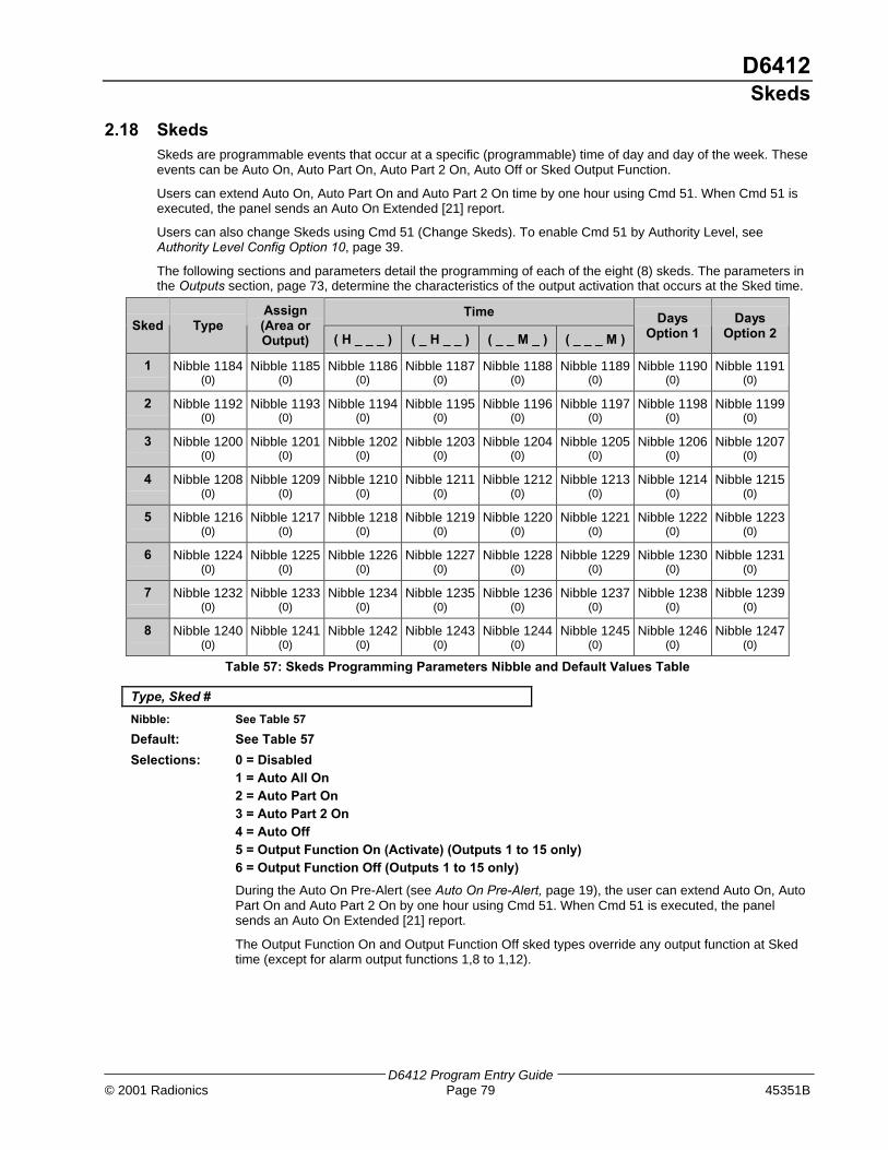
D6412Skeds
D6412 Program Entry Guide© 2001 Radionics Page 79 45351B
2.18 SkedsSkeds are programmable events that occur at a specific (programmable) time of day and day of the week. Theseevents can be Auto On, Auto Part On, Auto Part 2 On, Auto Off or Sked Output Function.
Users can extend Auto On, Auto Part On and Auto Part 2 On time by one hour using Cmd 51. When Cmd 51 isexecuted, the panel sends an Auto On Extended [21] report.
Users can also change Skeds using Cmd 51 (Change Skeds). To enable Cmd 51 by Authority Level, seeAuthority Level Config Option 10, page 39.
The following sections and parameters detail the programming of each of the eight (8) skeds. The parameters inthe Outputs section, page 73, determine the characteristics of the output activation that occurs at the Sked time.
TimeSked Type
Assign(Area orOutput) ( H _ _ _ ) ( _ H _ _ ) ( _ _ M _ ) ( _ _ _ M )
DaysOption 1
DaysOption 2
1 Nibble 1184(0)
Nibble 1185(0)
Nibble 1186(0)
Nibble 1187(0)
Nibble 1188(0)
Nibble 1189(0)
Nibble 1190(0)
Nibble 1191(0)
2 Nibble 1192(0)
Nibble 1193(0)
Nibble 1194(0)
Nibble 1195(0)
Nibble 1196(0)
Nibble 1197(0)
Nibble 1198(0)
Nibble 1199(0)
3 Nibble 1200(0)
Nibble 1201(0)
Nibble 1202(0)
Nibble 1203(0)
Nibble 1204(0)
Nibble 1205(0)
Nibble 1206(0)
Nibble 1207(0)
4 Nibble 1208(0)
Nibble 1209(0)
Nibble 1210(0)
Nibble 1211(0)
Nibble 1212(0)
Nibble 1213(0)
Nibble 1214(0)
Nibble 1215(0)
5 Nibble 1216(0)
Nibble 1217(0)
Nibble 1218(0)
Nibble 1219(0)
Nibble 1220(0)
Nibble 1221(0)
Nibble 1222(0)
Nibble 1223(0)
6 Nibble 1224(0)
Nibble 1225(0)
Nibble 1226(0)
Nibble 1227(0)
Nibble 1228(0)
Nibble 1229(0)
Nibble 1230(0)
Nibble 1231(0)
7 Nibble 1232(0)
Nibble 1233(0)
Nibble 1234(0)
Nibble 1235(0)
Nibble 1236(0)
Nibble 1237(0)
Nibble 1238(0)
Nibble 1239(0)
8 Nibble 1240(0)
Nibble 1241(0)
Nibble 1242(0)
Nibble 1243(0)
Nibble 1244(0)
Nibble 1245(0)
Nibble 1246(0)
Nibble 1247(0)
Table 57: Skeds Programming Parameters Nibble and Default Values Table
Type, Sked #
Nibble: See Table 57
Default: See Table 57
Selections: 0 = Disabled1 = Auto All On2 = Auto Part On3 = Auto Part 2 On4 = Auto Off5 = Output Function On (Activate) (Outputs 1 to 15 only)6 = Output Function Off (Outputs 1 to 15 only)
During the Auto On Pre-Alert (see Auto On Pre-Alert, page 19), the user can extend Auto On, AutoPart On and Auto Part 2 On by one hour using Cmd 51. When Cmd 51 is executed, the panelsends an Auto On Extended [21] report.
The Output Function On and Output Function Off sked types override any output function at Skedtime (except for alarm output functions 1,8 to 1,12).

D6412Skeds
D6412 Program Entry Guide45351B Page 80 © 2001 Radionics
Assign (Area or Output), Sked #
Nibble: See Table 57
Default: See Table 57
Selections: 0 = Disabled1 = Area 1 or Output 12 = Area 2 or Output 23 = Area 3 or Output 34 = Area 4 or Output 45 = Output 56 = Output 67 = Output 78 = Output 89 = Output 910 = Output 1011 = Output 1112 = Output 1213 = Output 1314 = Output 1415 = Output 15
Entering a zero (0) in this parameter disables the Sked.
If the Sked Type is Auto On or Auto Off, this parameter assigns an Area to the Sked.
If the Sked Type is Output Function On or Output Function Off, this parameter assigns aprogrammable output. How the programmable output functions at Sked time is determined in theOutputs section, page 73.
The output assigned to the Sked in this parameter can be any output function. At Sked time, theSked overrides that function.
The Sked function is only available for Outputs 1 to 15.
Time, Sked #
Nibble: See Table 57
Default: See Table 57 (0,0,0,0 = Sked Disabled)
Selections: 0 – 9
Enter the time of day that the Sked will occur. There are four digits in this entry, each oneoccupying a Nibble. Enter the time in 24-hour format (HHMM) where Midnight is 2400, noon is1200 and 12:01 am is 0001. Entering 0000 disables the Sked.

D6412Skeds
D6412 Program Entry Guide© 2001 Radionics Page 81 45351B
Days Option 1, Sked #
Nibble: See Table 57
Default: See Table 57
Selections: 0-15 (See Table 58)
Enter This Value to Select Options
Option 0 1 2 3 4 5 6 7 8 9 10 11 12 13 14 15
No Option Selected X
Every Day X X X X X X X X
Monday X X X X
Tuesday X X X X
Wednesday X X X X
Table 58: Skeds Days Option 1 Options
Use this parameter to determine the day of the week the Sked occurs.
Entering zero (0) for this parameter may disable the Sked if no selection is made at Sked 1 Days,Option 2.
Days Option 2, Sked #
Nibble: See Table 57
Default: See Table 57
Selections: 0-15 (See Table 59)
Enter This Value to Select Options
Option 0 1 2 3 4 5 6 7 8 9 10 11 12 13 14 15
No Option Selected X
Thursday X X X X X X X X
Friday X X X X X X X X
Saturday X X X X X X X X
Sunday X X X X X X X X
Table 59: Skeds Days Option 2 Options
Use this parameter to determine the day of the week the Sked occurs.
Entering zero (0) for this parameter may disable the Sked if no selection is made at Sked 1 Days,Option 1.

D6412SDI Bus Device Configuration
D6412 Program Entry Guide45351B Page 82 © 2001 Radionics
2.19 SDI Bus Device ConfigurationThe following parameters configure devices that connect to the SDI Bus on the D6412.
Reserved
Nibble: 1248
Premises RF Receiver Options
Nibble: 1249
Default: 0
Selections: 0 = No RF Receiver Connected1 = Receiver 1 Connected, Set Receiver to Address 502 = Receiver 2 Connected, Set Receiver to Address 513 = Receivers 1 and 2 Connected, Set Receiver 1 to Address 50, Receiver 2 to Address 514-8 = Reserved
This parameter tells the D6412 if a premises RF Receiver is connected.
Enter This Value to Select Options
Option 0 1 2 3 4 5 6 7 8
No RF Receiver Connected X
Receiver 1 Connected, Set Receiver to Address 50 X X
Receiver 2 Connected, Set Receiver to Address 51 X X
Table 60: Premises RF Receiver Options
• Receiver 1 Connected, Set Receiver to Address 50: RF Receiver 1 has been connected to thecontrol panel. Set the receiver’s address to 50 (jumper setting OFF). See page 132 for details onadding RF ID codes and RF transmitters and point states.
• Receiver 2 Connected, Set Receiver to Address 51: RF Receiver 2 has been connected to thecontrol panel. Set the receiver’s address to 51 (jumper setting ON). See page 132 for details onadding RF ID codes and RF transmitters and point states.
Premises RF Receiver, Supervision Interval
Nibble: 1250
Default: 5
Selections: 0 = No Supervision4 = 12 Hours5 = 24 Hours
Premises RF transmitters (sensors) send a supervisory signal approximately once every hour. Thepremises RF receiver expects to hear this signal from every transmitter in the interval determined inthis parameter. A “Missing” report is sent for each device that the RF receiver does not hear.
Supervision Interval for fire transmitters is fixed at 4 hours.
All the status reports for the receiverinclude the address. For example, ifthe cover is removed, Event 127 (SDITamper) is generated and sends thefollowing message in Modem IIIa2:“SDI Tamper Device 50.”
Options 4-8 forNibble 1249are reservedfor future use.

D6412SDI Bus Device Configuration
D6412 Program Entry Guide© 2001 Radionics Page 83 45351B
RF Jam Detect Level
Nibble: 1251
Default: 12
Selections: 0-15
This parameter configures the RF receivers for jam detection.
Radionics recommends that you leave the RF Jam Detect Level setting at the defaultunless advised by Radionics Technical Support.
Reserved
Nibble: 1252
D9533 RS-232 Module Output Configuration
Nibble: 1253
Default: 0
Selections: 0 = Disabled (No RS232 Module Connected)1 = RS232 Output in Log Format for Printer2 = RS232 Output in GSP Format
Set the D9533 to Address 250.
• RS-232 Output in Log Format for Printer: output is formatted ASCII text similar to the text thatappears in the text command center displays. Each log event is outputted in real time. Linebreaks are included making this option suitable for connecting a serial printer to the module.
If you connect a printer to the D9533 and get unexpected results, check the moduleoutput configuration (Nibble 1253), baud rate configuration (Nibble 1254) andparity/flow control/stop bit configuration (Nibble 1255) for proper settings.
• RS-232 Output is GSP Format: output is formatted in Gateway Serial Protocol. GSP protocolallows you to integrate the D6412 with future GSP-compatible devices.
D9533 RS-232 Module Configuration-Baud Rate
Nibble: 1254
Default: 2
Selections: 0 = 3001 = 12002 = 24003 = 48004 = 96005 = 14400
This parameter tells the panel what baud rates the D9533 supports.
If you connect a printer to the D9533 and get unexpected results, check the moduleoutput configuration (Nibble 1253), baud rate configuration (Nibble 1254) and parity/flowcontrol/stop bit configuration (Nibble 1255) for proper settings.

D6412SDI Bus Device Configuration
D6412 Program Entry Guide45351B Page 84 © 2001 Radionics
D9533 Module Configuration-Parity, Flow Control, Stop Bit
Nibble: 1255
Default: 0
Selections: 0-7 (See Table 61)
Parity Flow Control Stop BitsSelection
None Odd Even Software Hardware 1 2
0 X X X
1 X X X
2 X X X
3 X X X
4 X X X
5 X X X
6 X X X
7 X X X
Table 61: D9533 RS-232 Parity-Flow Control-Stop Bit Options
D624 Telephone Command Module, Access Options
Nibble: 1256
Default: 0
Selections: 0-15 (See Table 62)
Enter This Value to Select Options
Option 0 1 2 3 4 5 6 7 8 9 10 11 12 13 14 15
Disabled, No D624 Connected X
Access Granted to Users With Authority Level 1 X X X X X X X X
Access Granted to Users With Authority Level 2 X X X X X X X X
Access Granted to Users With Authority Level 3 X X X X X X X X
Access Granted to Users With Authority Level 4 X X X X X X X X
Table 62: D624 Telephone Command Module Access Options
Set this parameter to zero (0) if there are no D624 modules connected to the panel, or to disableany D624 modules that are connected to the panel.
Selecting any of the other options allows system control for users assigned to the chosen authoritylevel.
Reserved
Nibble: 1257-1265

D6412System Text
D6412 Program Entry Guide© 2001 Radionics Page 85 45351B
2.20 System TextNibbles are shown for each text parameter. When programming from the command center,selecting any nibble in the parameter puts you in special text programming mode that allows you toedit text blocks of 16 characters (see Appendix E: Programming from a Text Command Center).
Call for Service Text
Nibble: 1266-1297
Default: Blank
Selections: See Appendix E
This parameter provides 16 characters of programmable text to be displayed in the second line ofthe display whenever the first line is Call for Service. The following are possible entries forthe second line of text:
• Central Station phone number
• Preferred phone number called for service
• “Press 0 to View”, which will show system trouble details
[A] Key Text
Nibble: 1298-1329
Default: A Key Text
Selections: See Appendix E
[B] Key Text
Nibble: 1330-1361
Default: B Key Text
Selections: See Appendix E
[C] Key Text
Nibble: 1362-1393
Default: C Key Text
Selections: See Appendix E
D6412Area Text
D6412 Program Entry Guide45351B Page 86 © 2001 Radionics
2.21 Area TextArea 1 Name
Nibble: 1394-1425
Default: Area 1 Name TextSelections: See Appendix E
This parameter provides 16 characters of programmable text for Area 1. See the D6412 ProgramRecord Sheet (P/N 45350).
Area 1 Idle Text
Nibble: 1426-1457
Default: Not readySelections: See Appendix E
This parameter provides 16 characters of programmable text for Area 1 to be displayed when thesystem is idle (no alarms, no troubles, system disarmed). See the D6412 Program Record Sheet(P/N 45350).If “Don’t Show Point Status on Command Centers” is not selected (see Command Center #Options, page 46), the text command center displays “OK for All On” or “OK for Part On” across thesecond line. This indicates that all points are normal and the system is ready to arm All On or PartOn. If a point (controlled or 24-hour non-fire) is faulted (either open or shorted), the Area Idle Textfor this point’s assigned area replaces the “OK for All On/Part On” message.
If “Don’t Show Point Status on Command Centers” is selected, the default Area Idle Textdisplays as “Not Ready.” If no points are faulted, the Area Idle Text must be changed. See“Programming Text Nibbles”, page 131, for text entry instructions.
If a controlled point not configured for Part On arming is faulted (either open or shorted), “OK forPart On” replaces “OK for All On” on the text command center’s display. The system may be armedPart On, but cannot be armed All On until the faulted point is restored. See Options 1, Point Index##, page 61, for point index configuration details.
Area 2 Name
Nibble: 1458-1489Default: Area 2 Name TextSelections: See Appendix E
Area 2 Idle Text
Nibble: 1490-1521Default: Not readySelections: See Appendix E
Area 3 Name
Nibble: 1522-1553Default: Area 3 Name TextSelections: See Appendix E
Area 3 Idle Text
Nibble: 1554-1585Default: Not readySelections: See Appendix E
Area 4 Name
Nibble: 1586-1617
Default: Area 4 Name TextSelections: See Appendix E
Area 4 Idle Text
Nibble: 1618-1649
Default: Not readySelections: See Appendix E
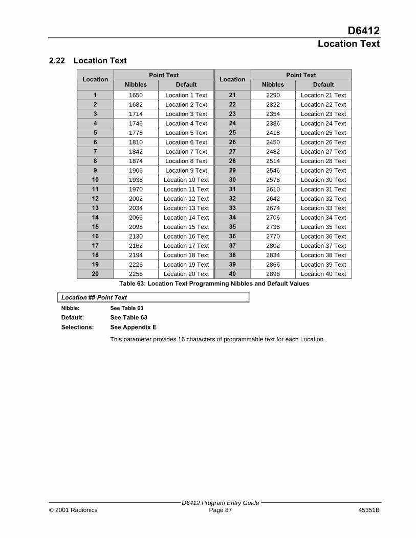
D6412Location Text
D6412 Program Entry Guide© 2001 Radionics Page 87 45351B
2.22 Location Text
Point Text Point TextLocation
Nibbles DefaultLocation
Nibbles Default
1 1650 Location 1 Text 21 2290 Location 21 Text
2 1682 Location 2 Text 22 2322 Location 22 Text
3 1714 Location 3 Text 23 2354 Location 23 Text
4 1746 Location 4 Text 24 2386 Location 24 Text
5 1778 Location 5 Text 25 2418 Location 25 Text
6 1810 Location 6 Text 26 2450 Location 26 Text
7 1842 Location 7 Text 27 2482 Location 27 Text
8 1874 Location 8 Text 28 2514 Location 28 Text
9 1906 Location 9 Text 29 2546 Location 29 Text
10 1938 Location 10 Text 30 2578 Location 30 Text
11 1970 Location 11 Text 31 2610 Location 31 Text
12 2002 Location 12 Text 32 2642 Location 32 Text
13 2034 Location 13 Text 33 2674 Location 33 Text
14 2066 Location 14 Text 34 2706 Location 34 Text
15 2098 Location 15 Text 35 2738 Location 35 Text
16 2130 Location 16 Text 36 2770 Location 36 Text
17 2162 Location 17 Text 37 2802 Location 37 Text
18 2194 Location 18 Text 38 2834 Location 38 Text
19 2226 Location 19 Text 39 2866 Location 39 Text
20 2258 Location 20 Text 40 2898 Location 40 Text
Table 63: Location Text Programming Nibbles and Default Values
Location ## Point Text
Nibble: See Table 63
Default: See Table 63
Selections: See Appendix E
This parameter provides 16 characters of programmable text for each Location.

D6412RF Keypads
D6412 Program Entry Guide45351B Page 88 © 2001 Radionics
2.23 RF KeypadsThe D6412 supports up to four RF keypads. Each keypad has two programming parameters. The RF keypadsreport low battery, tamper, etc. by point number (255, 254, 253, 252). The compatible RF keypads have notbeen investigated by UL.
RF Keypad Options(Default)
Area(Default)
Receiver 1SDI Address
Receiver 2SDI Address
1 Nibble 2930(0)
Nibble 2931(0)
52 60
2 Nibble 2932(0)
Nibble 2933(0)
53 61
3 Nibble 2934(0)
Nibble 2935(0)
54 62
4 Nibble 2936(0)
Nibble 2937(0)
55 63
Table 64: RF Keypad Programming Nibbles and Default Values
RF Keypad # Options
Nibble: See Table 64
Default: 0
Selections: See Table 65
Enter This Value to Select Options
RF Keypad Option 0 1 2 3 4 5 6 7 8 9 10 11 12 13 14 15
No Option Selected X
Reserved
Belongs to Receiver 2 X X
Supervised X X
Reserved
Table 65: RF Keypad Options
• Belongs to Receiver 2: RF Receiver 2 performs ID and monitoring functions for the commandcenter. If this option is not selected, the command center belongs to Receiver 1.
• Supervised: The receiver always supervises the command center and the panel ignores thesupervision based on the installer’s configuration of this option.
RF Keypad # Area
Nibble: See Table 64
Default: See Table 64
Selections: 0 = Disabled1 = Assign RF Keypad 1 to Area 12 = Assign RF Keypad 1 to Area 23 = Assign RF Keypad 1 to Area 34 = Assign RF Keypad 1 to Area 4
To enable a RF keypad it must be assigned to an Area.
To disable a RF keypad, enter a 0 at this parameter.
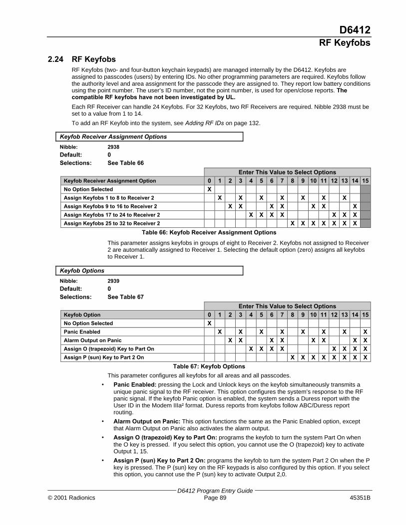
D6412RF Keyfobs
D6412 Program Entry Guide© 2001 Radionics Page 89 45351B
2.24 RF KeyfobsRF Keyfobs (two- and four-button keychain keypads) are managed internally by the D6412. Keyfobs areassigned to passcodes (users) by entering IDs. No other programming parameters are required. Keyfobs followthe authority level and area assignment for the passcode they are assigned to. They report low battery conditionsusing the point number. The user’s ID number, not the point number, is used for open/close reports. Thecompatible RF keyfobs have not been investigated by UL.
Each RF Receiver can handle 24 Keyfobs. For 32 Keyfobs, two RF Receivers are required. Nibble 2938 must beset to a value from 1 to 14.
To add an RF Keyfob into the system, see Adding RF IDs on page 132.
Keyfob Receiver Assignment Options
Nibble: 2938
Default: 0Selections: See Table 66
Enter This Value to Select OptionsKeyfob Receiver Assignment Option 0 1 2 3 4 5 6 7 8 9 10 11 12 13 14 15No Option Selected XAssign Keyfobs 1 to 8 to Receiver 2 X X X X X X XAssign Keyfobs 9 to 16 to Receiver 2 X X X X X X XAssign Keyfobs 17 to 24 to Receiver 2 X X X X X X XAssign Keyfobs 25 to 32 to Receiver 2 X X X X X X X
Table 66: Keyfob Receiver Assignment Options
This parameter assigns keyfobs in groups of eight to Receiver 2. Keyfobs not assigned to Receiver2 are automatically assigned to Receiver 1. Selecting the default option (zero) assigns all keyfobsto Receiver 1.
Keyfob Options
Nibble: 2939
Default: 0Selections: See Table 67
Enter This Value to Select OptionsKeyfob Option 0 1 2 3 4 5 6 7 8 9 10 11 12 13 14 15No Option Selected XPanic Enabled X X X X X X X XAlarm Output on Panic X X X X X X X XAssign O (trapezoid) Key to Part On X X X X X X X XAssign P (sun) Key to Part 2 On X X X X X X X X
Table 67: Keyfob Options
This parameter configures all keyfobs for all areas and all passcodes.
• Panic Enabled: pressing the Lock and Unlock keys on the keyfob simultaneously transmits aunique panic signal to the RF receiver. This option configures the system’s response to the RFpanic signal. If the keyfob Panic option is enabled, the system sends a Duress report with theUser ID in the Modem IIIa² format. Duress reports from keyfobs follow ABC/Duress reportrouting.
• Alarm Output on Panic: This option functions the same as the Panic Enabled option, exceptthat Alarm Output on Panic also activates the alarm output.
• Assign O (trapezoid) Key to Part On: programs the keyfob to turn the system Part On whenthe O key is pressed. If you select this option, you cannot use the O (trapezoid) key to activateOutput 1, 15.
• Assign P (sun) Key to Part 2 On: programs the keyfob to turn the system Part 2 On when the Pkey is pressed. The P (sun) key on the RF keypads is also configured by this option. If you selectthis option, you cannot use the P (sun) key to activate Output 2,0.

D6412Return to Default
D6412 Program Entry Guide45351B Page 90 © 2001 Radionics
2.25 Return to Default
Reserved
Nibble: 2940
Reserved
Nibble: 2941
Reserved
Nibble: 2942
Reserved
Nibble: 2943
Return to Defaults
Nibble: 2944
Default: 0
Selections: 0 = Maintain User-Specified Settings1 = Return All Parameters to Factory Defaults
Use this parameter to restore all of the manufacturer’s default settings for all parameters (includingthis one) by entering 1.
Reserved
Nibble: 2945
Reserved
Nibble: 2946

D6412Glossary
D6412 Program Entry Guide© 2001 Radionics Page 91 45351B
3.0 Glossary
24-Hour Point Points that are always on even when the system is turned off. Two types: Fire Points and Non-Fire 24-HourPoints.
Account Number The account number is the number the D6412 transmits to the receiver. It is not the passcode. The accountnumber is not sufficient identification to abort an alarm.
Area An installer specified collection of points that can be armed and disarmed independently. An area can report withit’s own account number. Opening, closing, alarm, trouble, and restoral reports are all associated with an area.You can organize the D6412’s points and users into up to four independent areas, in essence creating fourindependent systems with a single control/communicator.
Arming States
All On All controlled points are armed. All On with No Delay (Instant) is an option. No exit or entry delay is provided withthe No Delay option.
Part On An installer-defined subset of the controlled points is armed. Part with No Delay (Instant) is an option. No exit orentry delay is provided.
Part 2 On A user-defined subset of the controlled points is armed. Part 2 with No Delay (Instant) is an option. No exit orentry delay is provided.
Off The controlled points are not armed.
Authority Level A programmable feature that determines what a user can do in a given area.
Burglary AlarmTone
A constant warble tone.
Bypass To selectively remove points temporarily from the system.
Central Station A facility where trained personnel monitor a security system 24 hours a day. The security system may beprogrammed to contact the central station during alarm conditions, enabling central station personnel to dispatchthe proper authorities.
Checksum A method of checking accuracy of transmitted information. A number representing the total number of bits ofinformation transmitted is included with the transmission. The microprocessor counts the bits of informationreceived and compares its sum to the transmitted checksum number. If the numbers do not match, thetransmission is in error.
CommandCenter
The keypad from which the end-user initiates commands (functions).
Contact ID A communication format that utilizes standard DTMF tones for transmission of information.
Control/Communicator
A control/communicator combines the functionality of an alarm control panel and the functionality of a digital dialerin a single device. In the past the control panel and communication functions were provided on separate products.In the D6412 literature, including this document, control/communicator, control panel, control, and panel are usedinterchangeably.
Controlled Point A point that responds to alarm conditions depending upon whether the system is turned on or off.
Cross Point Two point types that are configured to initiate an alarm when both point types have been faulted. Fire pointscannot be set for Cross Point configuration.
DTMF Dialing Dual Tone Multi-Frequency. A standard signaling method for dialing and data transmission using a combination oftwo sine waves at different frequencies. Also commonly referred to as Touch-Tone signaling.
DuressPasscode
A passcode that arms and disarms a system just like a personal passcode does, however it also sends an alarmsignal to the central station without sounding an alarm on the premises.

D6412Glossary
D6412 Program Entry Guide45351B Page 92 © 2001 Radionics
Entry Delay A programmed delay of the system alarm responses that allow a person to enter the building through the entrydoor to turn the system off. An alarm response will begin if the building is not exited before the entry delayexpires.
Error Tone The same warble tone as the Trouble Tone, but not repeated.
Faulted Point A point that is not normal (e.g. – an open door or window).
Fire Alarm Tone A warble tone that is on for one second, then briefly off (repeatedly).
Follower Point A point programmed to initiate an instant alarm unless a delay point is faulted first. When a delay point is faultedfirst, the follower point assumes the entry delay time of the delay point.
Force Arming A method of overriding the safety feature that prevents arming with a faulted circuit on a control/communicator.
Global Something that affects the entire system (e.g. – global point configuration refers to the programmable featuresthat affect all points).
Groups The D6412 program parameters described in this manual are organized into groups. Most groups primarilycontain parameters that are related in some way. For example, the Authority Levels Group contains parametersthat configure the D6412’s four Authority Levels.
Handshake A signal sent by one end of the communications channel to the other indicating reception of signal.
Hold An instruction to press and hold a key to perform a function.
IndependentPoint Control
A device that allows a single point or zone on a control/communicator to be armed or disarmed independentlyfrom the rest of the system.
Instant Alarm A point type that initiates an alarm immediately when faulted. This point type does not follow any Entry/Exit delaytime.
Invisible Point A point that does not display at any command center during alarm or trouble conditions.
Keyfob A small, hand-held wireless device usually designed to fit on a key chain that consists of buttons that allow theuser to perform various functions, depending on the keyfob, such as arming/disarming the system, operatingoutputs or sending reports.
Keyswitch
Momentary To operate a momentary keyswitch, insert the key, turn it and then release it. The key returns to its startingposition automatically. The key cannot be removed unless it is in the starting position.
Maintained A maintained keyswitch typically has two positions marked “Armed” and “Disarmed.” To operate, insert the key,turn the key to the desired position and remove the key.
Latching The locking in of a circuit by means of a holding contact.
Location On the D6412 Control/Communicator, a “location” represents the following parameter assignments: Area, PointNumber and Device. A location tells the D6412 in which area a device is assigned and by which point number itreports.
Modem IIIa² Modem IIIa² is a Radionics reporting format (protocol) the D6412 uses to communicate to central stationreceivers. Even though you can program the D6412 to report in other formats only Modem IIIa² reports arereferenced in this document. If you choose an alternate reporting format use Appendix A in the D6412 ProgramEntry Guide to determine what report is substituted for the Modem IIIa² report.
Nibble Once the installer selects a value for a parameter, the panel stores the selection in E² memory ‘Nibbles’. Eachparameter uses one or more Nibbles. When programming from the Command Center, the installer enters theirselection directly into the memory Nibbles. When programming from the remote programmer, the installer needonly make one entry per parameter.
No Delay Turning the system on without Entry or Exit delay.

D6412Glossary
D6412 Program Entry Guide© 2001 Radionics Page 93 45351B
Off Display The display that appears when the system is turned off and no keys are pressed (normal display).
Options ‘Options’ are a unique type of parameter that allow the installer to configure up to four (4) features by entering avalue in a single Nibble.
PSTN Public Switched Telephone Network. An assembly of communications facilities and central office equipmentoperated jointly by authorized common carriers that provides the general public with the ability to establishcommunications channels via discrete dialing codes.
Parity A method of checking the accuracy of transmitted data by adding an extra bit to the number when necessary tomake the number odd or even.
Parameter Each program parameter sets a specific value or chooses an option.
Passcode A unique identification number issued at the time of installation of each system. This passcode is required tooperate the system (arm/disarm, test system, initiate commands, etc.) The passcode is not the same as theaccount number.
Points The D6412 reports changing conditions on the sensor loops it monitors as ‘point’ events. For example when thecondition on on-board sensor loop 1, changes from normal (supervised, end of line resistor in place) to ‘shorted’the panel can be programmed to create an alarm event for ‘point’ 1. That alarm event appears in command centerdisplays as ‘Alarm, Pt 1’. If programmed for reporting, the panel would send an ‘Alarm, Pt 1’ report to the centralstation receiver in the Modem IIIa² format. Other reporting formats typically use ‘Zones’ (Zn) in their reports inplace of point.
Point Index Used to construct “personality types” for points used in the D6412 system. Each unique point index numberdetermines responses to specific conditions occurring on the protective points.
Point Type Describes what the point does (for example – fire point, burglary point, 24-hour point, etc.).
Point Scan Time The amount of time that passes while a point is electrically off-normal. This duration determines the length of apulse.
Press/Push These are used interchangeably instructing you to push down and then release a key.
ProgrammableOutputs
The D6412 provides up to 20 programmable outputs. These outputs are activated by installer selectable panelevents. Event options include alarms, troubles, and scheduled events (Skeds).The D6412’s on-board points provide power or dry contact switching upon activation.When programmed to activate on alarm events outputs are sometimes described as ‘bell’.In some Modem IIIa² reports outputs are described as ‘relay’.
Pulse Count A feature of an intrusion detection system in which an alarm is triggered only after there has been a series ofdetections in a short period of time. A pulse count is used in difficult environments where false alarms areaproblem.
Pulse Dialing A method of selecting the called number by pulsing the phone line.
RAM IV RAM (Remote Account Manager) IV is a Windows-based account management and panel programming utilitydesigned to remotely set up and program specific control panels.
RemoteProgramming
System programming by means of the system user’s telephone line.
Restoral Report A signal transmitted upon the removal of a trouble or alarm condition from an alarm circuit.
Scope 1) A concept that limits the information presented to a given command center or printer. The boundaries are area-wide, account-wide or panel-wide. 2) A selected beginning and end points of a process – from an initial activity toa final activity – for the purpose of analysis.
SDI Serial Device Interface.
SKED A scheduling parameter that allows a selected event to happen at a specific time.

D6412Glossary
D6412 Program Entry Guide45351B Page 94 © 2001 Radionics
Swinger Bypass A programmable feature that determines the number of alarms or troubles the point can transmit in one hour. Ifthe number is exceeded, the point is bypassed for the remainder of the arming period.
Trouble A service condition that needs to be corrected, such as a broken wire.
Trouble Tone A warble tone that is on briefly, followed by a pause, followed by the warble tone (repeatedly).
Visible Point A point that displays at command centers during alarm or trouble conditions.
Warble Tone A tone that is on for one second, then briefly off.
Wink A slow LED flash rate used to indicate a specified status or condition.

D6412Appendix A
D6412 Program Entry Guide© 2001 Radionics Page 95 45351B
Appendix A: Routing Dialing TablesIntroduction
This appendix contains tables showing the dialing attempts for each Destination/Phone Number configuration.
There is not a “Phone 2 Only” option. If you wish to program only one phone number for a RoutingDestination, it must be Phone 1.
If Phone 1 is programmed to cancel Call Waiting, you should program Phone 2 without the CallWaiting cancel sequence. If the subscriber cancels Call Waiting without notifying the installingcompany, the panel will still be able to send reports using Phone 2. Dialing a Call Waiting sequenceon a non-Call Waiting line prevents the system from successfully dialing the central station.
Comm Fail EventA Communication Fail (Comm Fail) event is:
1. Clear (dump) the initiating report and any pending reports for the destination where the Comm Fail eventoccurred.
2. Create a Comm Fail [69] or AltComm Comm Fail [70] report which includes the Destination Number (1 or 2).Modem IIIa² reports report the destination number as a Route Group (RG). The Alternate Comm Fail reportis used when an alternate communications path is used (SAFECOM for example).
3. The Comm Fail, Comm Restoral [71], Alternate Comm Restore [72] reports follow the System StatusReports routing.
4. If the Comm Fail occurred on destination 1 and System Status Reports routing is set to Destination 2 or setto Destination 2 on Destination 1 fail, then send Comm Fail report.
5. If the Comm Fail occurred on destination 1 and System Status Reports routing is set to Destination 1 thensend a Comm Restore report with the next report for destination 1.
6. If the Comm Fail occurred on destination 2 and System Status Reports routing is set to Destination 1, thensend Comm Fail report.
7. If the Comm Fail occurred on destination 2 and System Status Reports routing is set to Destination 2 thensend a Comm Restore report with the next report for destination 2.
8. If a Comm Fail report is sent successfully to the ‘other’ destination, a Comm Restore event should be sentwhen there is a successful communication on the failed destination.
In the following tables an X shows the point where dialing attempts for a Routing Destination end (the lastattempt) and the Comm Fail event begins.
Routing Option – Destination 1 Only
Phone 1 Programmed Phone 1 and Phone 2 Programmed
Destination 1 Destination 2 Destination 1 Destination 2Attempt
Phone 1 Phone 2 Phone 1 Phone 2Attempt
Phone 1 Phone 2 Phone 1 Phone 2
1 X 1 X
2 X 2 X
3 X 3 X
4 X 4 X
5 X 5 X
6 6
7 7
8 8
9 9
10 10
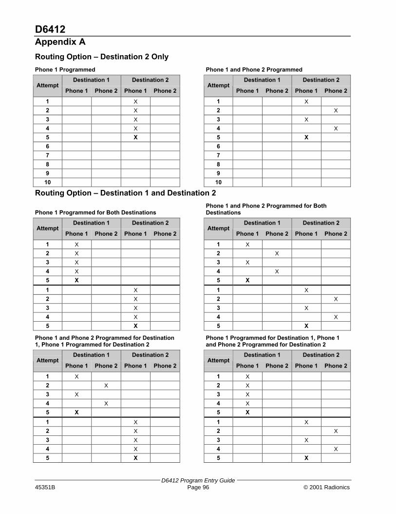
D6412Appendix A
D6412 Program Entry Guide45351B Page 96 © 2001 Radionics
Routing Option – Destination 2 Only
Phone 1 Programmed Phone 1 and Phone 2 Programmed
Destination 1 Destination 2 Destination 1 Destination 2Attempt
Phone 1 Phone 2 Phone 1 Phone 2Attempt
Phone 1 Phone 2 Phone 1 Phone 2
1 X 1 X
2 X 2 X
3 X 3 X
4 X 4 X
5 X 5 X
6 6
7 7
8 8
9 9
10 10
Routing Option – Destination 1 and Destination 2
Phone 1 Programmed for Both DestinationsPhone 1 and Phone 2 Programmed for BothDestinations
Destination 1 Destination 2 Destination 1 Destination 2Attempt
Phone 1 Phone 2 Phone 1 Phone 2Attempt
Phone 1 Phone 2 Phone 1 Phone 2
1 X 1 X
2 X 2 X
3 X 3 X
4 X 4 X
5 X 5 X
1 X 1 X
2 X 2 X
3 X 3 X
4 X 4 X
5 X 5 X
Phone 1 and Phone 2 Programmed for Destination1, Phone 1 Programmed for Destination 2
Phone 1 Programmed for Destination 1, Phone 1and Phone 2 Programmed for Destination 2
Destination 1 Destination 2 Destination 1 Destination 2Attempt
Phone 1 Phone 2 Phone 1 Phone 2Attempt
Phone 1 Phone 2 Phone 1 Phone 2
1 X 1 X
2 X 2 X
3 X 3 X
4 X 4 X
5 X 5 X
1 X 1 X
2 X 2 X
3 X 3 X
4 X 4 X
5 X 5 X

D6412Appendix B
D6412 Program Entry Guide© 2001 Radionics Page 97 45351B
Appendix B: Panel Event and Reporting FormatsIntroduction
The following table includes each D6412 panel event, the description for each event as it appears in the panellog, the reports sent for each event, the point types linked to the event and the RAM IV Event Alert Groupnumber.
The last column, Status Reports, indicates System Status events. An R indicates that reports for the event followthe System Status routing. An S indicates that the event following the System Status Swinger Count. Systemreports do not include an Area number; they use the account number for Area 1.
Following the table is a description of the Basic Pager reporting format. The event numbers shown in the PanelEvents and Reporting Formats table are the same numbers that will show up on a pager for each correspondingreport.
Panel Event and Reporting Formats Table
Event#
Event as shownin Panel Log
Modem IIIa²Report
Contact ID Report Event DescriptionPoint Types
Linked toEvent
RAM IVEventGroup
StatusReports
01 AC Fail AC Fail 301 AC Loss AC Power to panel interrupted. 12 R S
02 AC Restore AC Restoral 301 AC Loss AC Power to panel restored. 12 R S
03 Alarm,Tamper Alarm 137 Tamper Alarm, Tamper Point Type. 4-Tamper 3
04 Alarm,Emergency Alarm 101 PersonalEmergency
Alarm, Emergency Point Typeor ABC key programmed foremergency response.
5- EmergencyEmergencyKey
3
05 Alarm,Panic Alarm 120 Panic Alarm, Panic-Visible PointType.
6- Visible PanicEmergencyKey
3
06 Alarm,Invisible Alarm 120 Panic Alarm, Panic- Invisible PointType or ABC key programmedfor panic response.
7-InvisiblePanicEmergencyKey
3
07 Alarm,24-hr Burg Alarm 133 24 Hr Safe Alarm, Burglary Point Type orIndependent Point Control PointType.
8- Burglary9- IndependentPoint Control
3
08 Alarm,Cntrl,Dly Alarm 134 Entry/Exit Alarm, Delay 1 or Delay 2 PointType.
11- Delay 112- Delay 2
3
09 Alarm,Cntrl Alarm 130 Burglary Alarm, Keyswitch or Follower orInstant Point Types.
10- Keyswitch13- Follower14- Instant
3
10 Cross,Tamper Alarm CrossPoint
137 Tamper Alarm, Tamper Point Type withCross Point Option selected.
4-Tamper 3
11 Cross,Emergency Alarm CrossPoint
101 PersonalEmergency
Alarm, Emergency Point Typewith Cross Point Optionselected.
5- Emergency 3
12 Cross,Panic Alarm CrossPoint
120 Panic Alarm, Panic-Visible Point Typewith Cross Point Optionselected.
6- Visible Panic 3
13 Cross,Invisible Alarm CrossPoint
120 Panic Alarm, Panic- Invisible PointType with Cross Point Optionselected.
7-InvisiblePanic
3
14 Cross,24hr Burg Alarm CrossPoint
133 24 Hr Safe Alarm, Burglary Point Type withCross Point Option selected
8- Burglary 3
15 Cross,Cntrl,Dly Alarm CrossPoint
134 Entry/Exit Alarm, Delay 1 or Delay 2 PointType with Cross Point Optionselected.
11- Delay 112- Delay 2
3
16 Cross,Cntrl Alarm CrossPoint
130 Burglary Alarm, Keyswitch or Follower orInstant Point Types with CrossPoint Option selected.
13- Follower14- Instant
3
Table 68: Panel Events and Reporting Formats

D6412Appendix B
D6412 Program Entry Guide45351B Page 98 © 2001 Radionics
Event#
Event as shownin Panel Log
Modem IIIa²Report
Contact ID Report Event DescriptionPoint Types
Linked toEvent
RAM IVEventGroup
StatusReports
17 Cross,Unverified UnverifiedEvent Burglary
378 Cross-zoneTrouble1
A fault on one non-fire pointtype with the Cross PointOption selected. This is not analarm event.
any with CrossPoint Option
3
18 Alarm Exit Error Alarm ExitError
374 Exit Error(zone)
Point faulted at the end of exitdelay.
11- Delay 112- Delay 2
3
19 Alrm Recent Clse Alarm, RecentClosing
134 Entry/Exit2 Alarm event within 2 minutes ofclosing.
11- Delay 112- Delay 2
3
20 Alrm Recent Clse Alarm, RecentClosing
130 Burglary2 Alarm event within 2 minutes ofclosing.
10- Keyswitch13- Follower14- Instant
3
21 Auto On Extended Extend CloseTime by Area
464 Auto-arm TimeExtended
Auto On sked delayed one hourby user. Report followsOpen/Close routing.
10
22 Battery Low Battery Low 302 Low SystemBattery
Panel battery is low. 12 R S
23 Battery Missing Battery Missing 311 BatteryMissing/Dead
Panel battery is missing. Verylow, shorted, or open batteriesare reported as missing.
12 R S
24 Rstrl Batt Low BatteryRestoral
302 Low SystemBattery
Battery restoral from lowbattery.
12 R S
25 Rstrl Bat Missng BatteryRestoral
311 BatteryMissing/Dead
Battery Restoral from missigingbattery
12 R S
26 Bypass,Fire,User CommandBypass
571 Fire bypass Selective bypass by user, firepoint types
1- Fire2- Fire withAlarmVerification
15
27 Bypass,Fire,RAM IV
RemoteBypass (no callback) RemoteBypass (callback)
571 Fire bypass Selective bypass by RAM IV,fire point types.
1- Fire2- Fire withAlarmVerification
28 Bypass,Ctrl,User CommandBypass
570 Zone/Sensorbypass
Selective bypass by user,controlled point types.
10 to 14-ControlledPoint Types
15
29 Bypass,Ctrl,RAM IV
RemoteBypass (no callback) RemoteBypass (callback)
570 Zone/Sensorbypass
Selective bypass by RAM IV,controlled point types.
10 to 14-ControlledPoint Types
30 Bypass,24hr,User CommandBypass
572 24-Hr ZoneBypass
Selective bypass by user, 24-hour non-fire point types.
2 to 9- 24-hour,Non-Fire PointTypes
15
31 Bypass,24hr,RAM IV
RemoteBypass (no callback) RemoteBypass (callback)
572 24-Hr ZoneBypass
Selective bypass by RAM IV,24-hour non-fire point types.
2 to 9- 24-hour,Non-Fire PointTypes
32 Bypass,Forced Pt Forced Point 570 Zone/Sensorbypass
Point force armed at forcearming.
10 to 14-ControlledPoint Types
15
33 Bypass,Swinger SwingerBypass
575 SwingerBypass
Point swinger bypassed. All point types 15
34 UnBypss,Fire, Usr BypassRestore (point< 256) (FirePoint)
571 Fire bypass User cleared bypass(unbypass), Fire point types.
1- Fire2- Fire withAlarmVerification
15
Table 68 (cont.): Events and Reporting Formats

D6412Appendix B
D6412 Program Entry Guide© 2001 Radionics Page 99 45351B
Event#
Event as shownin Panel Log
Modem IIIa²Report
Contact ID Report Event DescriptionPoint Types
Linked toEvent
RAM IVEventGroup
StatusReports
35 UnBypss,Ctrl,Usr BypassRestore (point< 256)
570 Zone/Sensorbypass
User cleared bypass(unbypass), Controlled pointtypes.
10 to 14-ControlledPoint Types
15
36 UnBypss,24hr,Usr BypassRestore (point< 256)
572 24-Hr ZoneBypass
User cleared bypass(unbypass), 24-hour pointtypes.
2 to 9- 24-hour,Non-Fire PointTypes
15
37 Call for Service ServiceRequest
616 ServiceRequest
This report sent automatically atCall for Service Interval. It doesnot indicate a trouble condition.
12 R
38 Cancel Alarm Cancel Alarm(non-fire)
406 Cancel User acknowledged activealarm before bell time expired,non-fire point types.
8
39 Cancel Fire Fire Cancel 406 Cancel User acknowledged activealarm before bell time expired,fire point types.
7
40 CheckSum Fail Check SumFail
303 RAMChecksum Bad
Checksum on panel’sparameters failed. Panelprogram should be verified.
12 R S
41 ChckSum Fail,SDI ParameterChecksum Fail(SDI Devicereported)
330 SystemPeripheral trouble
Checksum on SDI deviceparameters failed. Deviceshould be checked.
12 R S
42 Cls,All,+Dly,Skd Closing byArea
403 Automatic O/C System turned All On withEntry/Exit delay by Sked.
10
43 Cls,All,+Dly,KS Closing byArea
409 Keyswitch O/C System turned All On withEntry/Exit delay by Keyswitch.
10
44 Cls,All,+Dly,
RAM IV
Closing byArea
400 Open/Close System turned All On withEntry/Exit delay by RAM IV.
45 Cls,All,+Dly,Tel Closing byArea
407 RemoteArm/Disarm
System turned All On withEntry/Exit delay by Telephone.
10
46 Cls,All,+Dly,Usr Closing byArea
401 O/C by User System turned All On withEntry/Exit delay by User.
10
47 Cls,All,-Dly,RAM IV Closing byArea
400 Open/Close System turned All On with nodelay (instant) by RAM IV.
48 Cls,All,-Dly,Usr Closing byArea
401 O/C by User System turned All On with nodelay (instant) by User.
10
49 Cls,Prt,+Dly,Skd PerimeterDelay by Area
456 Partial Arm System turned Part On withEntry/Exit delay by Sked.
10
50 Cls,Prt,+Dly,KS PerimeterDelay by Area
442 KeyswitchArmed Stay
System turned Part On withEntry/Exit delay by Keyswitch.
10
51 Cls,Prt,+Dly,
RAM IV
PerimeterDelay by Area
456 Partial Arm System turned Part On withEntry/Exit delay by RAM IV.
52 Cls,Prt,+Dly,Usr PerimeterDelay by Area
456 Partial Arm System turned Part On withEntry/Exit delay by User.
10
53 Cls,Prt,-Dly,
RAM IV
PerimeterInstant by Area
456 Partial Arm System turned Part On with nodelay (instant) by RAM IV.
54 Cls,Prt,-Dly,Usr PerimeterInstant by Area
456 Partial Arm System turned Part On with nodelay (instant) by User.
10
55 Frc,All,+Dly,Skd Forced Closingby Area
403 Automatic O/C System forced All On withEntry/Exit delay by Sked. 3
10
56 Frc,All,+Dly,KS Forced Closingby Area
400 O/C System forced All On withEntry/Exit delay by Keyswitch. 3
10
57 Frc,All,+Dly,
RAM IV
Forced Closingby Area
400 O/C System forced All On withEntry/Exit delay by RAM IV. 3
Table 68 (cont.): Events and Reporting Formats

D6412Appendix B
D6412 Program Entry Guide45351B Page 100 © 2001 Radionics
Event#
Event as shownin Panel Log
Modem IIIa²Report
Contact ID Report Event DescriptionPoint Types
Linked toEvent
RAM IVEventGroup
StatusReports
58 Frc,All,+Dly,Tel Forced Closingby Area
400 O/C System forced All On withEntry/Exit delay by Telephone. 3
10
59 Frc,All,+Dly,Usr Forced Closingby Area
401 O/C by User System forced All On withEntry/Exit delay by User. 3
10
60 Frc,All,-Dly,RAM IV Forced Closingby Area
400 O/C System forced All On with nodelay (instant) by RAM IV. 3
61 Frc,All,-Dly,Usr Forced Closingby Area
401 O/C by User System forced All On with nodelay (instant) by User. 3
10
62 Frc,Prt,+Dly,Skd Forced ClosePerimeterDelay by Area
456 Partial Arm System forced Part On withEntry/Exit delay by Sked. 3
10
63 Frc,Prt,+Dly,KS Forced ClosePerimeterDelay by Area
456 Partial Arm System forced Part On withEntry/Exit delay by Keyswitch. 3
10
64 Frc,Prt,+Dly,
RAM IV
Forced ClosePerimeterDelay by Area
456 Partial Arm System forced Part On withEntry/Exit delay by RAM IV. 3
65 Frc,Prt,+Dly,Usr Forced ClosePerimeterDelay by Area
456 Partial Arm System forced Part On withEntry/Exit delay by User. 3
10
66 Frc,Prt,-Dly,
RAM IV
Forced ClosePerimeterInstant by Area
456 Partial Arm System forced Part On with nodelay (instant) by RAM IV. 3
67 Frc,Prt,-Dly,Usr Forced ClosePerimeterInstant by Area
456 Partial Arm System forced Part On with nodelay (instant) by User. 3
10
68 Point Closing Point Closing Point closed by IndependentPoint Control (D268/269 orD279).
9- IndependentPoint Control
10
69 Comm Fail Comm Fail(route groupreported)
354 Failure tocommunicateevent
Report failed to reach routingdestination. The RoutingDestination number (1 or 2)reported as Route Group inModem IIIa² reports.
12 R S
70 CommFail,
AltComm
Comm Fail(route groupand SDI devicereported)
354 Failure tocommunicateevent
Report failed to reach routingdestination configured forAlternate Communication. TheRouting Destination number (1or 2) reported as Route Groupin Modem IIIa² reports. SDIdevice number for AlternateCommunication Modulereported in Modem IIIa² .
12 R S
71 Comm Restoral CommRestoral (routegroup reported)
354 Failure tocommunicateevent
After communication fail, reportsent sucessfully to routingdestination. The RoutingDestination number (1 or 2)reported as Route Group inModem IIIa² reports.
12 R S
72 CommRstl,
AltComm
CommRestoral (routegroup and SDIdevicereported)
354 Failure tocommunicateevent
After communication fail, reportsent sucessfully to routingdestination configured forAlternate Communication. TheRouting Destination number (1or 2) reported as Route Groupin Modem IIIa² reports. SDIdevice number for AlternateCommunication Modulereported in Modem IIIa² .
12 R S
Table 68 (cont.): Events and Reporting Formats

D6412Appendix B
D6412 Program Entry Guide© 2001 Radionics Page 101 45351B
Event#
Event as shownin Panel Log
Modem IIIa²Report
Contact ID Report Event DescriptionPoint Types
Linked toEvent
RAM IVEventGroup
StatusReports
73 Date/Time Change Date Changed 625 Time/Datereset
Date/Time in panel changed. 12 R
74 Duress Duress 121 Duress User entered Duress passcodeor pressed panic key sequenceon RF Keyfob. The duressreport is sent in addition to anyother report theat the user’saction would generate.
1
75 Fire,Alarm Fire Alarm 110 Fire Alarm event on fire point type. 1- Fire2- Fire withAlarmVerification
2
76 Fire,Cross Fire AlarmCrossed Point
110 Fire Verified alarm event on firepoint type with Cross PointOption. See Cross Point Option,page 63
1- Fire2- Fire withAlarmVerification
2
77 Fire,Un-verified UnverifiedEvent-Fire
378 Cross-zoneTrouble
Unverified alarm event on firepoint type with Cross PointOption. See Cross Point Option,page 63 Or unverified event onFire Verify point type. See page58.
1- Fire2- Fire withAlarmVerification
5
78 Fire, Missing Fire Missing 373 Fire Trouble Fire point type assigned to pointexpander (wired or RF) notresponding to panel’s statuspoll.
1- Fire2- Fire withAlarmVerification
5
79 Fire,Alrm,Rstl Fire Restoralfrom Alarm
110 Fire Restoral from alarm, Fire pointtypes
1- Fire2- Fire withAlarmVerification
7
80 Fire,Trouble Fire Trouble 373 Fire Trouble Trouble condition on Fire pointtypes
1- Fire2- Fire withAlarmVerification
5
81 Fire,Trbl,Rstl Fire RestoralfromTrouble/Missing/Supervision
373 Fire Trouble Restoral from Trouble, Firepoint types.
1- Fire2- Fire withAlarmVerification
7
82 Instl Mode,Start Service Start 466 Service OnPremises
Installer passcode entered.Installer mode accessed.
11 R
83 Instl Mode,End Service End 466 Service OffPremises
Installer mode exited. 11 R
84 Log Overflow Log Overflow 624 Event LogOverflow
Panel log overflow condition.Oldest events beingoverwritten.
12 R
85 Log Threshold Log Threshold 620 Event Log Panel log reached threshold.See Log SupervisionConfiguration, page 19.
12 R
86 AltCom Low Signl Low SignalStrengthlll=level,ppp=path
350CommunicationTrouble
Low Signal Strength detectedon Alternate Communicationdevice.
12 R S
87 Missing,Alarm Missing Alarm 140 General Alarm Point assigned to pointexpander (wired or RF) notresponding to panel’s statuspoll while system is armed.
Any non-firepoint type
3
Table 68 (cont.): Events and Reporting Formats

D6412Appendix B
D6412 Program Entry Guide45351B Page 102 © 2001 Radionics
Event#
Event as shownin Panel Log
Modem IIIa²Report
Contact ID Report Event DescriptionPoint Types
Linked toEvent
RAM IVEventGroup
StatusReports
88 Missing,Trouble MissingTrouble
382 Loss of super-RPM
Point assigned to pointexpander (wired or RF) notresponding to panel’s statuspoll while system is disarmed.
Any non-firepoint type
6
89 Open,Skd Opening byArea
403 Automatic O/C Opening by Sked. 10
90 Open,RAM IV Opening byArea
400 Open/Close Opening by RAM IV.
91 Open,Usr Opening byArea
401 O/C by User Opening by user, by IDreported.
10
92 Open,KS Opening byArea
409 Keyswitch O/C Opening by Keyswitch. 10
93 Open,Skd,Alarm Opening byArea fromAlarm
403 Automatic O/C Opening after Alarm event bySked.
10
94 Open,RAMIV,Alarm
Opening byArea fromAlarm
400 Open/Close Opening after Alarm event byRAM IV.
95 Open,Usr,Alarm Opening byArea fromAlarm
401 O/C by User Opening after Alarm event, IDreported.
10
96 Open,KS,Alarm Opening byArea fromAlarm
409 Keyswitch O/C Opening after Alarm event byKeyswitch
10
97 Point Opening Point Opening Point opened by IndependentPoint Control (D268/269 orD279).
10
98 Params Changed ParametersChanged
306 PanelProgrammingChanged
Panel Parameters Changed 12 R
99 Phone Line Fail Phone LineFail (Line 1)
351 Telco 1 fault Phone line voltage less than 3volts for 40 seconds.
12 R S
100 Phone Line Rstl Phone LineRestoral (Line1)
351 Telco 1 fault After Phone Line Fail event,phone line voltage detected atgreater than 3 volts for 40seconds.
12 R S
101 Bad Call to RAM IV Fail to CallRAM IV
413 Unsuccessfulaccess
Panel attempted call to RAM IV,but was unsucessful.
12 R
102 RAM IV AccessFail
Invalid RemoteAccess
413 Unsucessfulaccess
RAM IV attempted to connect topanel but was not sucessful.
R
103 RAM IV AccessOK
Valid RemoteAccess
412 SuccessfulDownload/Access
RAM IV sucessfully connectedto and disconnected from panel.
R
104 Re-Boot,Panel Re-Boot 305 System reset Normal start up or reset withstandby jumper.
R S
105 Re-Boot,SDI Re-Boot (SDI #reported)
339 Exp. ModuleReset
Unexpected reset (reboot) fromSDI device.
12 R S
106 Output Reset,Usr Relay Reset(by User)
320 Sounder/Relay Output Reset by User 16 R
107 Output Reset,Skd Relay Reset(by Sked)
320 Sounder/Relay Output Reset by Sked 16 R
108 Output Reset,
RAM IV
Relay Reset(by RAM IV)
320 Sounder/Relay Output Reset by RAM IV R
109 Output Set,Usr Relay Set (byuser)
320 Sounder/Relay Output Set by User 16 R
110 Output Set,Skd Relay Set (bySked)
320 Sounder/Relay Output Set by Sked 16 R
Table 68 (cont.): Events and Reporting Formats

D6412Appendix B
D6412 Program Entry Guide© 2001 Radionics Page 103 45351B
Event#
Event as shownin Panel Log
Modem IIIa²Report
Contact ID Report Event DescriptionPoint Types
Linked toEvent
RAM IVEventGroup
StatusReports
111 Output Set,RAM IV Relay Set (byRAM IV)
320 Sounder/Relay Output Set by RAM IV R
112 Rstrl,Tamper Restoral fromAlarm
137 Tamper Restoral from alarm, Tamperpoint type.
4- Tamper 8
113 Rstrl,Emergency Restoral fromAlarm
101 PersonalEmergency
Restoral from alarm,Emergency point type.
5- Emergency 8
114 Rstrl,Panic Restoral fromAlarm
120 Panic Restoral from alarm, Panicpoint type.
6- Visible Panic 8
115 Rstrl,Invisible Restoral fromAlarm
120 Panic Restoral from alarm, Invisiblepoint type.
7-InvisiblePanic
8
116 Rstrl,24-hr Burg Restoral fromAlarm
133 24hr (Safe) Restoral from alarm, 24-hourburglary point types.
8- Burglary9- IndependentPoint Control
8
117 Rstrl,Cntrl,Dly Restoral fromAlarm
134 Entry/Exit Restoral from alarm, controlledpoint types.
11- Delay 112- Delay 2
8
118 Rstrl,Cntrl Restoral fromAlarm
130 Burglary Restoral from alarm, controlledpoint types.
10- Keyswitch13- Follower14- Instant
8
119 Rcvr Jam RFInterference
344 RF ReceiverJam Detect
Jammed condition detected onpremises RF receiver.
9 R S
120 Rcvr Jam Rstl RFInterferenceRestoral
344 RF ReceiverJam DetectRestoral
Jammed condition detected onpremises RF receiver cleared.
9 R S
121 RF Battery Low RF TransmitterLow Battery
384 RF LowBattery
Low Battery detected onpremises RF transmitter.
Any point type 9
122 RF Battery Rstl RF TransmitterBatteryRestore
384 RF LowBattery
Low Battery condition detectedon premises RF transmittercleared.
Any point type 9
123 RF Tamper Trbl RF TransmitterTamperTrouble
383 SensorTamper
Premises RF TransmitterTamper Trouble
Any point type 9
124 RF Tamper Rstl RF TransmitterTamperRestoral
383 SensorTamper
Premises RF TransmitterTamper Restoral
Any point type 9
125 SDI Missing SDI-Fail(Missing)
333 Exp. ModuleFailure
SDI device not responding topolling.
12 R S
126 SDI Missing,Rstl SDI-Fail(Missing)Restoral
333 Exp. ModuleFailure
SDI device declared as missingnow responding to polling.
12 R S
127 SDI Tamper SDI-Tamper 341 Exp. ModuleTamper
Tamper open on SDI DeviceTamper.
12 R S
128 SDI Tamper,Rstl SDI-TamperRestoral
341 Exp. ModuleTamper
SDI Device Tamper Restoral. 12 R S
129 SDI Trouble SDI-Trouble 330 SystemPeripheral Trouble
Trouble detected on SDIDevice.
12 R S
130 SDI Trouble,Rstl SDI-TroubleRestoral
330 SystemPeripheral Trouble
SDI (Option Bus) DeviceTrouble condition cleared.
12 R S
131 SDI OverCurrent SDI-Overcurrent
330 SystemPeripheral Trouble
Over current condition detectedon SDI device.
12 R S
132 SDI OverCur,Rstl SDI-OvercurrentRestoral
330 SystemPeripheral Trouble
Over current condition on SDIdevice restored.
12 R S
133 Sensor Mon Trbl Sensor Trouble 391 Sensor Watchtrouble
Sensor trouble detected. Seepage 68 for a description ofSensor Monitor feature. Reportsfollow point trouble routing.
6
Table 68 (cont.): Events and Reporting Formats
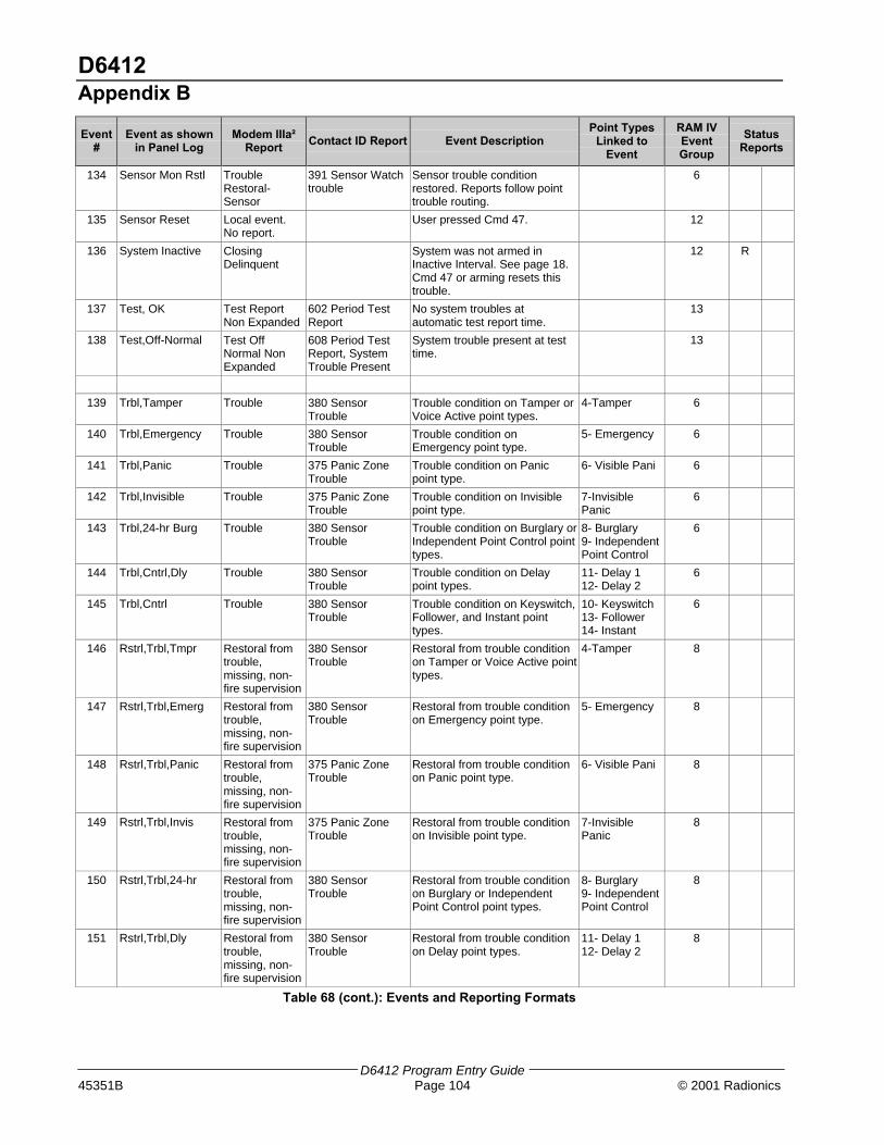
D6412Appendix B
D6412 Program Entry Guide45351B Page 104 © 2001 Radionics
Event#
Event as shownin Panel Log
Modem IIIa²Report
Contact ID Report Event DescriptionPoint Types
Linked toEvent
RAM IVEventGroup
StatusReports
134 Sensor Mon Rstl TroubleRestoral-Sensor
391 Sensor Watchtrouble
Sensor trouble conditionrestored. Reports follow pointtrouble routing.
6
135 Sensor Reset Local event.No report.
User pressed Cmd 47. 12
136 System Inactive ClosingDelinquent
System was not armed inInactive Interval. See page 18.Cmd 47 or arming resets thistrouble.
12 R
137 Test, OK Test ReportNon Expanded
602 Period TestReport
No system troubles atautomatic test report time.
13
138 Test,Off-Normal Test OffNormal NonExpanded
608 Period TestReport, SystemTrouble Present
System trouble present at testtime.
13
139 Trbl,Tamper Trouble 380 SensorTrouble
Trouble condition on Tamper orVoice Active point types.
4-Tamper 6
140 Trbl,Emergency Trouble 380 SensorTrouble
Trouble condition onEmergency point type.
5- Emergency 6
141 Trbl,Panic Trouble 375 Panic ZoneTrouble
Trouble condition on Panicpoint type.
6- Visible Pani 6
142 Trbl,Invisible Trouble 375 Panic ZoneTrouble
Trouble condition on Invisiblepoint type.
7-InvisiblePanic
6
143 Trbl,24-hr Burg Trouble 380 SensorTrouble
Trouble condition on Burglary orIndependent Point Control pointtypes.
8- Burglary9- IndependentPoint Control
6
144 Trbl,Cntrl,Dly Trouble 380 SensorTrouble
Trouble condition on Delaypoint types.
11- Delay 112- Delay 2
6
145 Trbl,Cntrl Trouble 380 SensorTrouble
Trouble condition on Keyswitch,Follower, and Instant pointtypes.
10- Keyswitch13- Follower14- Instant
6
146 Rstrl,Trbl,Tmpr Restoral fromtrouble,missing, non-fire supervision
380 SensorTrouble
Restoral from trouble conditionon Tamper or Voice Active pointtypes.
4-Tamper 8
147 Rstrl,Trbl,Emerg Restoral fromtrouble,missing, non-fire supervision
380 SensorTrouble
Restoral from trouble conditionon Emergency point type.
5- Emergency 8
148 Rstrl,Trbl,Panic Restoral fromtrouble,missing, non-fire supervision
375 Panic ZoneTrouble
Restoral from trouble conditionon Panic point type.
6- Visible Pani 8
149 Rstrl,Trbl,Invis Restoral fromtrouble,missing, non-fire supervision
375 Panic ZoneTrouble
Restoral from trouble conditionon Invisible point type.
7-InvisiblePanic
8
150 Rstrl,Trbl,24-hr Restoral fromtrouble,missing, non-fire supervision
380 SensorTrouble
Restoral from trouble conditionon Burglary or IndependentPoint Control point types.
8- Burglary9- IndependentPoint Control
8
151 Rstrl,Trbl,Dly Restoral fromtrouble,missing, non-fire supervision
380 SensorTrouble
Restoral from trouble conditionon Delay point types.
11- Delay 112- Delay 2
8
Table 68 (cont.): Events and Reporting Formats

D6412Appendix B
D6412 Program Entry Guide© 2001 Radionics Page 105 45351B
Event#
Event as shownin Panel Log
Modem IIIa²Report Contact ID Report Event Description
Point TypesLinked to
Event
RAM IVEventGroup
StatusReports
152 Rstrl,Trbl,Cntrl Restoral fromtrouble,missing, non-fire supervision
380 SensorTrouble
Restoral from trouble conditionon Keyswitch, Follower, andInstant point types.
10- Keyswitch13- Follower14- Instant
8
153 User Code AreaSet
User Level Set User Code ‘added’ by assigningarea.
16 R
154 User Code Change User CodeChanged
User Code changed. 16 R
155 User Code Delete User CodeDeleted
User Code deleted. 16 R
156 User Code Tamper User CodeTamper
461 Wrong CodeEntry
Invalid User Codes entered atkeypad exceeded User Tamperretry count. See page 41.
16 R
157 User Level Set User Level Set User Level set. 16 R
158 Walk Test Start Walk Test Start 607 Walk TestMode
Walk Test started with Cmd 44. 11
159 Walk Test End Walk Test End 607 Walk TestMode
Walk Test ended by user ortimed out.
11
160 Siren Trouble Output-Trouble 320 Sounder Relay Trouble condition detected onProgramable Output 2configured as supervised sirenoutput.
12 R S
161 Siren Restoral Output-Restore 320 Sounder Relay Trouble condition on supervisedsiren output cleared.
12 R S
162 Grnd Fault Ground Fault 310 Ground Fault Ground fault detected on panelssensor loops, SDI bus, or Auxpower outputs.
12 R S
163 Grnd Fault, Rstl Ground Fault,Restoral
310 Ground Fault Ground fault condition cleared. 12 R S
164 First Open Opening byAccount
400 Open/Close Panel is configured for multiplearea first to open, last to closefunctionality. See page 33. Firstarea has opened.
10
165 Last Close Closing byAccount
400 Open/Close Panel is configured for multiplearea first to open, last to closefunctionality. See page 33. Lastarea has closed.
10
166 AltCom Cond NetworkConditionppp=path,nnn=condition
350CommunicationTrouble
Trouble detected on AlternateCommunication network.Trouble condition is onlyspecified in Modem IIIa² report
12 R S
167 AltComm Fail NetworkFailureppp=path,nnn=condition
350CommunicationTrouble
Network failure detected onAlternate Communicationnetwork. Trouble condition isonly specified in Modem IIIa²report
12 R S
168 AltComm Rstrl NetworkRestoralppp=path,nnn=condition
350CommunicationTrouble
Network failure detected onAlternate Communicationnetwork. Trouble condition isonly specified in Modem IIIa²report
12 R S
169 Reserved 12 R S
170 Reserved 12 R S
171 Reserved 12 R S
172 Reserved 12 R S
Table 68 (cont.): Events and Reporting Formats
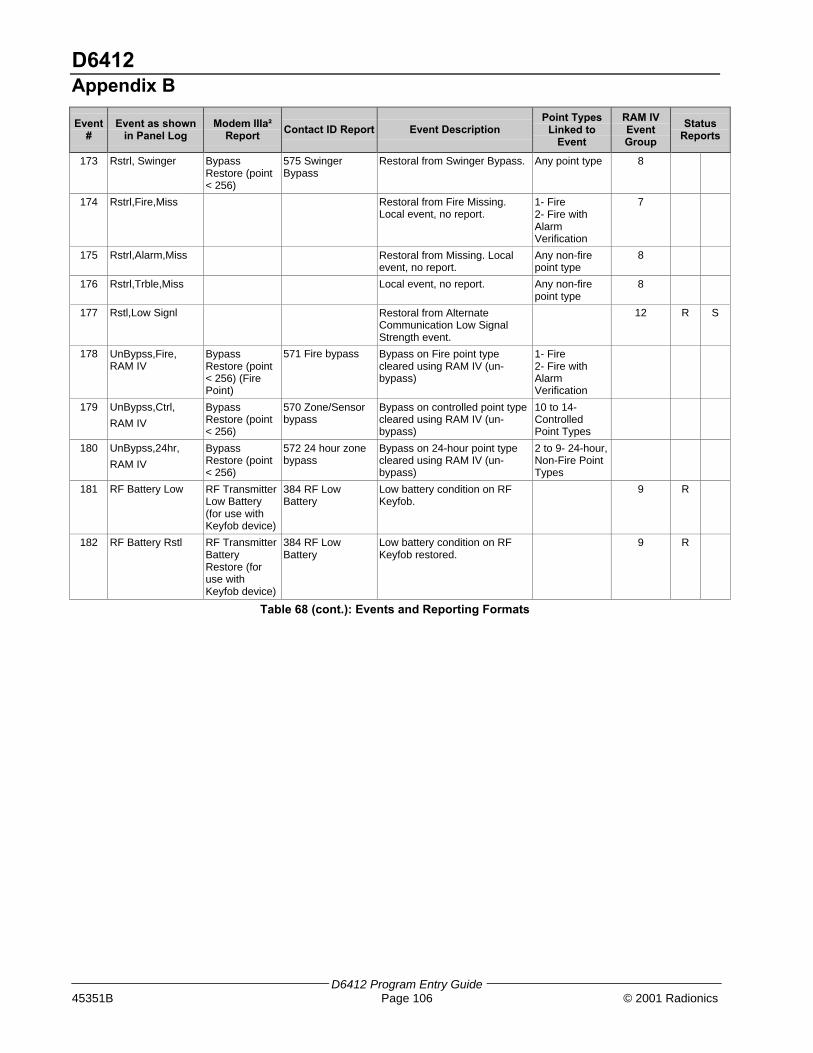
D6412Appendix B
D6412 Program Entry Guide45351B Page 106 © 2001 Radionics
Event#
Event as shownin Panel Log
Modem IIIa²Report
Contact ID Report Event DescriptionPoint Types
Linked toEvent
RAM IVEventGroup
StatusReports
173 Rstrl, Swinger BypassRestore (point< 256)
575 SwingerBypass
Restoral from Swinger Bypass. Any point type 8
174 Rstrl,Fire,Miss Restoral from Fire Missing.Local event, no report.
1- Fire2- Fire withAlarmVerification
7
175 Rstrl,Alarm,Miss Restoral from Missing. Localevent, no report.
Any non-firepoint type
8
176 Rstrl,Trble,Miss Local event, no report. Any non-firepoint type
8
177 Rstl,Low Signl Restoral from AlternateCommunication Low SignalStrength event.
12 R S
178 UnBypss,Fire,RAM IV
BypassRestore (point< 256) (FirePoint)
571 Fire bypass Bypass on Fire point typecleared using RAM IV (un-bypass)
1- Fire2- Fire withAlarmVerification
179 UnBypss,Ctrl,
RAM IV
BypassRestore (point< 256)
570 Zone/Sensorbypass
Bypass on controlled point typecleared using RAM IV (un-bypass)
10 to 14-ControlledPoint Types
180 UnBypss,24hr,
RAM IV
BypassRestore (point< 256)
572 24 hour zonebypass
Bypass on 24-hour point typecleared using RAM IV (un-bypass)
2 to 9- 24-hour,Non-Fire PointTypes
181 RF Battery Low RF TransmitterLow Battery(for use withKeyfob device)
384 RF LowBattery
Low battery condition on RFKeyfob.
9 R
182 RF Battery Rstl RF TransmitterBatteryRestore (foruse withKeyfob device)
384 RF LowBattery
Low battery condition on RFKeyfob restored.
9 R
Table 68 (cont.): Events and Reporting Formats

D6412Appendix B
D6412 Program Entry Guide© 2001 Radionics Page 107 45351B
Basic Pager FormatConfiguring the D6412 for Basic Pager Format
Setting a Routing Destination to Basic Pager format configures the D6412 to send reports to a numeric pager. Toutilize the Basic Pager format:
1. Enter the phone number for the pager in the ‘Phone Number 1’ parameter for the Routing Destination youhave chosen as the Basic Pager Destination.
The D6412’s Basic Pager format does not wait for an acknowledgement tone from the pager serviceprovider to send its report to the pager. It dials the phone number, waits 250 milliseconds and then sendsthe report. To increase the delay (pause), add delay characters as needed to the end of the phone number.See Table 69 for the valid phone number entries.
2. Set the ‘Format for Destination 1 (2)’ parameter to ‘Basic Pager’ for the Routing Destination you havechosen as the Basic Pager Destination.
Set the routing for any reports you would like sent to the pager to the Routing Destination (1 or 2) you havechosen as the Basic Pager destination.
Report digits are dialed as 100-millisecond DTMF tone pulses with 100-millisecond pauses between the digits.
Configuring a Pager Display
A pager’s display can show up to four fields of information in the order as shown below:
(Account Number) - (Event Number) - (Area Number) - (Point/User Number)
The data entered to set up a pager display follows the numbers entered for the panel’s routing phone numbers.
See Table 69 for the valid phone number entries.
The following examples show how to set up a pager display with different fields showing with and withoutseparators. The following variables will be used for each example:
− Phone Number: 978-1580
− Account Number: 1234
− Event Number: 08 (can be a 2- or 3-digit number)
− Area Number: 03
− Point Faulted: 21
Pager Display with All 4 Fields and No Separators
To set up a pager display that shows all four fields without any separators between fields, enter the PhoneNumber Nibbles as shown below:
− Nibble Entry: 9-7-8-1-5-8-10-13-13-13-0-#-0
− Resulting Pager Display: 1234080321
• The first 7 digits entered (9, 7, 8, 1, 5, 8, 10) make up the sample phone number (to enter “0”,key in “10” at the Command Center). Three pause characters (13, 13, 13 follow the phonenumber).
• The 11th digit, “0”, is the phone number terminator. This digit is always a “0” (zero).
• The 12th digit, “#” (entered as “12” at the Command Center), turns off all field separators.Without any field separators, the digits will appear as shown above without any spacing betweenfield groupings.
• The 13th digit, “0”, is the separator/field terminator. This digit is always a “0” (zero).
• The absence of a “*” (asterisk) entry will show all four fields in the following order: AccountNumber, Event Number, Area Number and Point Number.

D6412Appendix B
D6412 Program Entry Guide45351B Page 108 © 2001 Radionics
Pager Display with All 4 Fields with Separators
To set up a pager display that shows all four areas with separators between fields, enter the Phone NumberNibbles as shown below:
− Nibble Entry: 9-7-8-1-5-8-10-13-13-13-0-0
− Resulting Pager Display: 1234-08-03-21
• The first 7 digits entered (9, 7, 8, 1, 5, 8, 10) make up the sample phone number (to enter “0”,key in “10” at the Command Center). Three pause characters (13, 13, 13 follow the phonenumber).
• The 11th digit, “0”, is the phone number terminator. This digit is always a “0” (zero).
• The 12th digit, “0”, is the separator/field terminator. This digit is always a “0” (zero).
• The absence of a “#” entry inserts separators (-) between each field.
• The absence of a “*” (asterisk) entry will show all four fields in the following order: AccountNumber, Event Number, Area Number and Point Number.
Pager Display with First 3 Fields with Separators
To set up a pager display that shows the first three fields (Account Number, Event Number, and Area Number)with separators between fields, enter the Phone Number Nibbles as shown below:
− Nibble Entry: 9-7-8-1-5-8-10-13-13-13-0-*-*-*-0
− Resulting Pager Display: 1234-08-03
• The first 7 digits entered (9, 7, 8, 1, 5, 8, 10) make up the sample phone number (to enter “0”,key in “10” at the Command Center). Three pause characters (13, 13, 13 follow the phonenumber).
• The 11th digit, “0”, is the phone number terminator. This digit is always a “0” (zero).
• The 12th, 13th and 14th digits, “*” (asterisk entered as “11” at the Command Center), will showthe first three fields in the following order: Account Number, Event Number and Area Number.
• The 15th digit, “0” is the separator/field terminator. This digit is always a “0” (zero).
• The absence of a “#” entry inserts separators (-) between each field. To turn the separators off,enter a “#” after the phone number terminator.
Pager Display with First 2 Fields with Separators
To set up a pager display that shows the first two fields (Account Number and Event Number) with separatorsbetween fields, enter the Phone Number Nibbles as shown below:
− Nibble Entry: 9-7-8-1-5-8-10-13-13-13-0-*-*-0
− Resulting Pager Display: 1234-08
• The first 7 digits entered (9, 7, 8, 1, 5, 8, 10) make up the sample phone number (to enter “0”,key in “10” at the Command Center). Three pause characters (13, 13, 13 follow the phonenumber).
• The 11th digit, “0”, is the phone number terminator. This digit is always a “0” (zero).
• The 12th and 13th digits, “*” (asterisk entered as “11” at the Command Center), will show the firsttwo fields in the following order: Account Number and Event Number.
• The 14th digit, “0” is the separator/field terminator. This digit is always a “0” (zero).
• The absence of a “#” entry inserts separators (-) between each field. To turn the separators off,enter a “#” after the phone number terminator.

D6412Appendix B
D6412 Program Entry Guide© 2001 Radionics Page 109 45351B
Pager Display with First Field Only
To set up a pager display that shows only the first field (Account Number), enter the Phone Number Nibbles asshown below:
− Nibble Entry: 9-7-8-1-5-8-10-13-13-13-0-*-0
− Resulting Pager Display: 1234
• The first 7 digits entered (9, 7, 8, 1, 5, 8, 10) make up the sample phone number (to enter “0”,key in “10” at the Command Center). Three pause characters (13, 13, 13 follow the phonenumber).
• The 11th digit, “0”, is the phone number terminator. This digit is always a “0” (zero).
• The 12th digit, “*” (asterisk entered as “11” at the Command Center), will show the first field(Account Number) only.
• The 13th digit, “0”, is the separator/field terminator. This digit is always a “0” (zero).
Table 69 shows the selections for any phone number.
Digit to be Dialed Enter at the Command Center
1 1
2 2
3 3
4 4
5 5
6 6
7 7
8 8
9 9
0 10
* 11
# 12
p (4 second pause) 13
f (on-hook, pause, off-hook) 14
??? 15
t (terminate) 0
Table 69: Phone Number Selections
Any pauses that need to be entered in the dialing sequence (phone number) must go before the firstterminator.
The number of pauses required will vary based on the requirements of the specific paging servicebeing used.
Pre-testing should be performed to determine the correct number of pauses used to correctlyestablish panel communications by the pager sequence.
If the point/user number is three digits, the leading digit is omitted. For example, “252” displays as“52.”

D6412Appendix C
D6412 Program Entry Guide45351B Page 110 © 2001 Radionics
Appendix C: SDI Address TableTable 70 shows the SDI addresses for the different devices that can be connected to the D6412’s SDI bus.
All the status reports for the receiver include the address. For example, if the cover is removed, Event 127 (SDITamper) is generated and sends the following message in Modem IIIa2: “SDI Tamper Device 50.”
SDI Address Device Description
0 Installer Keypad or local connection to RAM IV
1-8 Command Centers 1 to 8
40, 41 D624 Telephone Control Module
50 Premises RF Receiver 1
51 Premises RF Receiver 2
52-55 Premises RF Keypads Receiver 1
60-63 Premises RF Keypads Receiver 2
101-107 D9528 Wired Point Expanders
150,151 D9529 Octo-Outputs and/or D9529-X10 Output Module
250 D9533 Serial RS232 Interface
Table 70: SDI Address and Device Assignments

D6412Appendix D
D6412 Program Entry Guide© 2001 Radionics Page 111 45351B
Appendix D: Operation GuideText Command Center
The system remembers passcodes entered for approximately 10 seconds after you have stoppedpressing keys. To log out of the system, press the [Cmd] key twice. “Logged Out” will appear on theCommand Center display.
The Text Command Center provides two lines of 16-character text for programming and general systemoperation. The command center may have up to 21 keys that perform various functions as described below.
Keys
1, 2, 3, 4, 5, 6, 7, 8, 9, 0 Numeric keys are used for entering passcodes, programming values, etc.
Cmd The Cmd and numeric keys enter commands (for example, Cmd 41).
All On Turns the system All On.
Part On Turns the system Part On.
No Delay Turns the system All or Part On with no entry or exit delay.
Bypass Bypasses specified points.
∗∗ Advances to the next display (when available).
ABC
An emergency function (Fire, Panic or Emergency Alarms) may be assigned tothese keys. Press the key twice to activate its special function. Each key must belabeled with its assigned function.
Tones
The Text Command Center also emits various tones, as described below.
Fire Alarm A repeated warble tone (on for one second then briefly off) emitted when a fire pointactivates.
Burglary Alarm A continuous warble tone emitted when a burglary point activates. See Bell Time,page 71, for details on setting the duration of this tone.
Trouble A repeated warble tone (on briefly followed by a pause followed by the warble tone)emitted when a system component is not functioning properly.
Key Press Short tone indicating a key press.
Entry Delay An intermittent tone that sounds upon entry (entry delay) and serves as a reminderto turn the system off.
Exit Delay An intermittent beep indicating exit delay and counting down to arming.
Error Warble tone (same as Trouble but not repeated) indicating an invalid entry.
OK Single beep (one second) indicating an accepted entry.
Watch Tone indicating a faulted watch point. Duration of the tone is determined bySelecting Watch Tone, page 120.
Backlight and Volume Control
See Keypad Adjust (Cmd 49), page 112, for instructions on adjusting the command center’s keystroke volumeand display brightness.
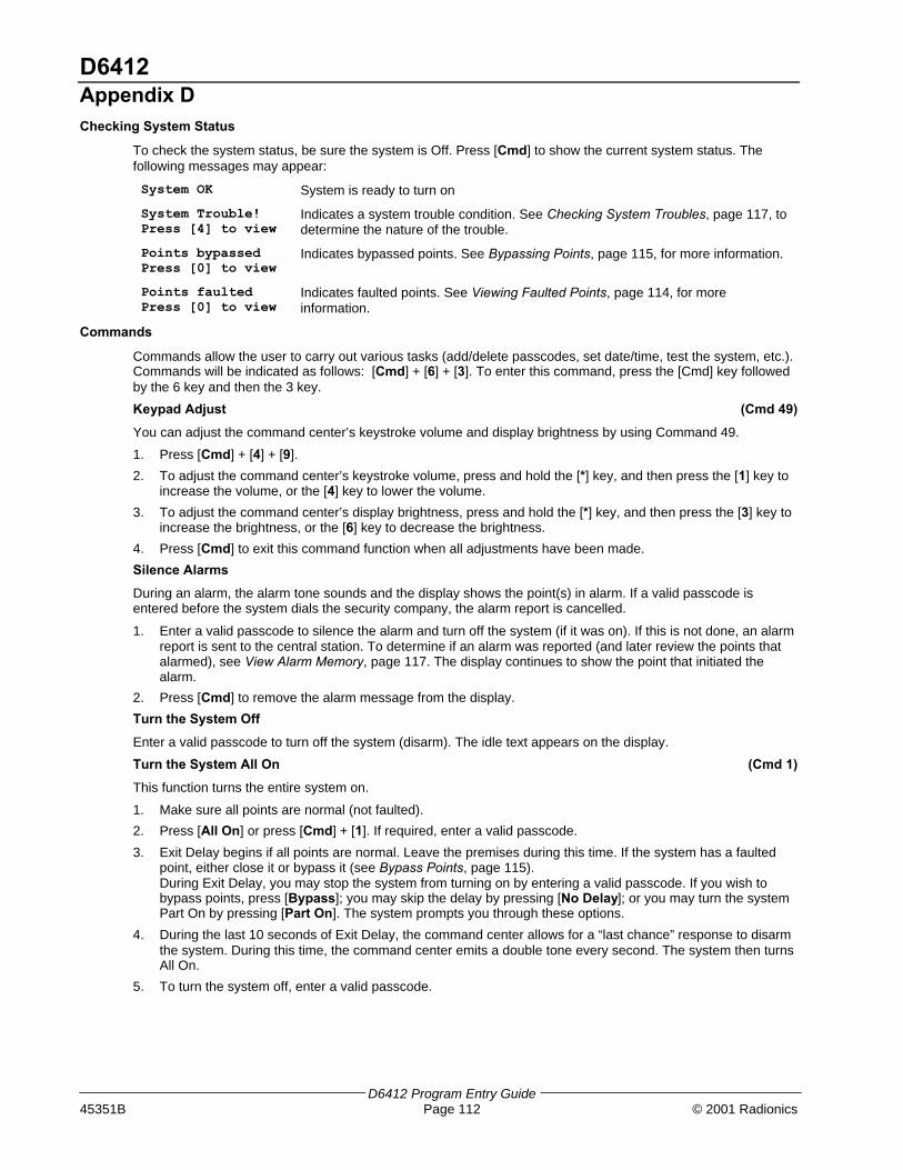
D6412Appendix D
D6412 Program Entry Guide45351B Page 112 © 2001 Radionics
Checking System Status
To check the system status, be sure the system is Off. Press [Cmd] to show the current system status. Thefollowing messages may appear:
System OK System is ready to turn on
System Trouble!Press [4] to view
Indicates a system trouble condition. See Checking System Troubles, page 117, todetermine the nature of the trouble.
Points bypassedPress [0] to view
Indicates bypassed points. See Bypassing Points, page 115, for more information.
Points faultedPress [0] to view
Indicates faulted points. See Viewing Faulted Points, page 114, for moreinformation.
Commands
Commands allow the user to carry out various tasks (add/delete passcodes, set date/time, test the system, etc.).Commands will be indicated as follows: [Cmd] + [6] + [3]. To enter this command, press the [Cmd] key followedby the 6 key and then the 3 key.
Keypad Adjust (Cmd 49)
You can adjust the command center’s keystroke volume and display brightness by using Command 49.
1. Press [Cmd] + [4] + [9].
2. To adjust the command center’s keystroke volume, press and hold the [*] key, and then press the [1] key toincrease the volume, or the [4] key to lower the volume.
3. To adjust the command center’s display brightness, press and hold the [*] key, and then press the [3] key toincrease the brightness, or the [6] key to decrease the brightness.
4. Press [Cmd] to exit this command function when all adjustments have been made.
Silence Alarms
During an alarm, the alarm tone sounds and the display shows the point(s) in alarm. If a valid passcode isentered before the system dials the security company, the alarm report is cancelled.
1. Enter a valid passcode to silence the alarm and turn off the system (if it was on). If this is not done, an alarmreport is sent to the central station. To determine if an alarm was reported (and later review the points thatalarmed), see View Alarm Memory, page 117. The display continues to show the point that initiated thealarm.
2. Press [Cmd] to remove the alarm message from the display.
Turn the System Off
Enter a valid passcode to turn off the system (disarm). The idle text appears on the display.
Turn the System All On (Cmd 1)
This function turns the entire system on.
1. Make sure all points are normal (not faulted).
2. Press [All On] or press [Cmd] + [1]. If required, enter a valid passcode.
3. Exit Delay begins if all points are normal. Leave the premises during this time. If the system has a faultedpoint, either close it or bypass it (see Bypass Points, page 115).During Exit Delay, you may stop the system from turning on by entering a valid passcode. If you wish tobypass points, press [Bypass]; you may skip the delay by pressing [No Delay]; or you may turn the systemPart On by pressing [Part On]. The system prompts you through these options.
4. During the last 10 seconds of Exit Delay, the command center allows for a “last chance” response to disarmthe system. During this time, the command center emits a double tone every second. The system then turnsAll On.
5. To turn the system off, enter a valid passcode.

D6412Appendix D
D6412 Program Entry Guide© 2001 Radionics Page 113 45351B
Turn the System Part On (Cmd 2)
This function turns on part of the system, leaving the rest of the system Off.
1. Make sure all points are normal (not faulted).
2. Press [Part On] or press [Cmd] + [2]. If all Part points are normal, the Exit Delay time starts. If there arefaulted points, return them to normal or bypass them. The command center may prompt you to enter apasscode.
3. Enter a valid passcode if necessary. During exit delay, you may stop the system from turning on by enteringa valid passcode. If you wish to turn the system Part On with No Delay, press [No Delay], or you maybypass points by pressing [Bypass].
4. During the last 10 seconds of Exit Delay, the command center allows for a “last chance” response to disarmthe system. During this time, the command center emits a double tone every second. The system then turnsPart On.
5. To turn the system off, enter a valid passcode.
Turn the System Part 2 On (Cmd 3)
This command turns on part of the system, leaving the rest of the system Off. Part 2 points are assigned by theuser (refer to Set Part 2 Points).
1. Make sure all points are normal (not faulted).
2. Press [Cmd] + [3] to turn the system Part 2 On. The command center may prompt you to enter a passcode.
3. Enter a valid passcode if necessary. During Exit Delay, you may stop the system from turning on by enteringa valid passcode. If you wish to turn the system Part 2 On with No Delay, press [No Delay], or you maybypass points by pressing [Bypass].
4. During the last 10 seconds of Exit Delay, the command center allows for a “last chance” response to disarmthe system. During this time, the command center emits a double tone every second. The system then turnsPart On.
5. To turn the system off, enter a valid passcode.
Set Part 2 Points (Cmd 65)
Use this command to assign points that arm when the system is turned Part 2 On.
1. Make sure the system is turned off (On indicator is off).
2. Press [Cmd] + [6] + [5]. The command center may prompt you to enter a passcode.
3. Enter a valid passcode if necessary. The command center displays the available points to assign to Part 2.
4. Enter the Point Number (1 through 40) and press [∗] to toggle it Yes or No for Part 2 (Yes = Active, ready todetect intrusion / No = Non-active, you can move freely without sounding an alarm). Repeat this procedureuntil all the desired points are selected for Part 2.
5. Press [Cmd] to exit this function.
Turn the System On with No Delay
This command allows you to turn the system All On, Part On or Part 2 On without Entry or Exit delays. Turningthe system on with no delay allows no Exit or Entry Delay time through the designated delay point (for example,Front Door). This function is useful when staying in the premises but with the system on.
1. Make sure all points are normal (not faulted).
2. Press [All On] to turn the system All On, or press [Part On] to turn the system Part On. To turn the systemPart 2 On, press [Cmd] + [3]. The command center may prompt you to enter a passcode.
3. Enter a valid passcode if necessary. The command center displays prompt you to bypass points, if desired.If all points are normal, press [No Delay] to turn the system on with no delay.During the last 10 seconds of Exit Delay, the command center allows for a “last chance” response to disarmthe system. During this time, the command center emits a double tone every second. The system then turnsAll or Part On.
4. To turn off the system, enter a valid passcode.
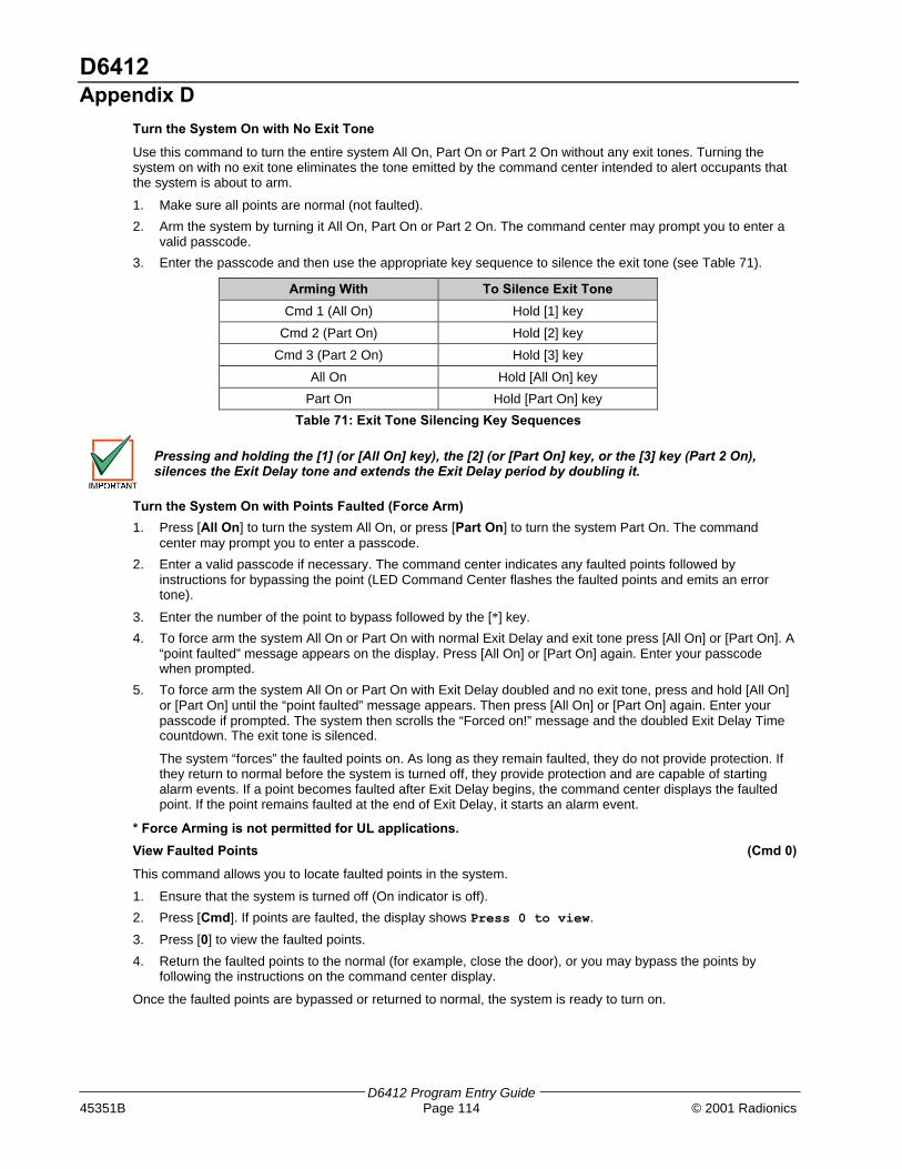
D6412Appendix D
D6412 Program Entry Guide45351B Page 114 © 2001 Radionics
Turn the System On with No Exit Tone
Use this command to turn the entire system All On, Part On or Part 2 On without any exit tones. Turning thesystem on with no exit tone eliminates the tone emitted by the command center intended to alert occupants thatthe system is about to arm.
1. Make sure all points are normal (not faulted).
2. Arm the system by turning it All On, Part On or Part 2 On. The command center may prompt you to enter avalid passcode.
3. Enter the passcode and then use the appropriate key sequence to silence the exit tone (see Table 71).
Arming With To Silence Exit Tone
Cmd 1 (All On) Hold [1] key
Cmd 2 (Part On) Hold [2] key
Cmd 3 (Part 2 On) Hold [3] key
All On Hold [All On] key
Part On Hold [Part On] key
Table 71: Exit Tone Silencing Key Sequences
Pressing and holding the [1] (or [All On] key), the [2] (or [Part On] key, or the [3] key (Part 2 On),silences the Exit Delay tone and extends the Exit Delay period by doubling it.
Turn the System On with Points Faulted (Force Arm)
1. Press [All On] to turn the system All On, or press [Part On] to turn the system Part On. The commandcenter may prompt you to enter a passcode.
2. Enter a valid passcode if necessary. The command center indicates any faulted points followed byinstructions for bypassing the point (LED Command Center flashes the faulted points and emits an errortone).
3. Enter the number of the point to bypass followed by the [∗] key.
4. To force arm the system All On or Part On with normal Exit Delay and exit tone press [All On] or [Part On]. A“point faulted” message appears on the display. Press [All On] or [Part On] again. Enter your passcodewhen prompted.
5. To force arm the system All On or Part On with Exit Delay doubled and no exit tone, press and hold [All On]or [Part On] until the “point faulted” message appears. Then press [All On] or [Part On] again. Enter yourpasscode if prompted. The system then scrolls the “Forced on!” message and the doubled Exit Delay Timecountdown. The exit tone is silenced.
The system “forces” the faulted points on. As long as they remain faulted, they do not provide protection. Ifthey return to normal before the system is turned off, they provide protection and are capable of startingalarm events. If a point becomes faulted after Exit Delay begins, the command center displays the faultedpoint. If the point remains faulted at the end of Exit Delay, it starts an alarm event.
* Force Arming is not permitted for UL applications.
View Faulted Points (Cmd 0)
This command allows you to locate faulted points in the system.
1. Ensure that the system is turned off (On indicator is off).
2. Press [Cmd]. If points are faulted, the display shows Press 0 to view.
3. Press [0] to view the faulted points.
4. Return the faulted points to the normal (for example, close the door), or you may bypass the points byfollowing the instructions on the command center display.
Once the faulted points are bypassed or returned to normal, the system is ready to turn on.

D6412Appendix D
D6412 Program Entry Guide© 2001 Radionics Page 115 45351B
Bypass Points
Use this command to bypass one or more points before turning the system All On, Part On or Part 2 On. You canaccess bypassed points when the system is turned on without causing an alarm.
1. Ensure that the system is turned off (On indicator is off).
2. Press [Bypass]. The command center may prompt you to enter a passcode.
3. Enter a valid passcode if necessary. The command center scrolls a list of points that can be bypassed.
4. Enter the number of the point to bypass (1-40) followed by the [∗] key. Repeat this step until all thenecessary points are bypassed.If a point is already bypassed, the command center instructs you on how to unbypass the point. Thecommand center alerts you if a point cannot be bypassed.
5. Press [Cmd] to exit this function.
Date and Time (Cmd 45)
Use this command to set the date and time in the system.
1. Press [Cmd] + [4] [5]. The command center may prompt you to enter a passcode.
2. Enter a valid passcode if necessary. The command center prompts you to enter the date and time(MM/DD/YY HH:MM).
3. Enter the date and time (in 24-hour format) using the numeric keys. After you make your entries, thecommand center displays the date and time entered before returning to the normal display.
In the event of a power cycle (power to the system is lost and then is restored), the D6412 takes the last event inthe log and uses that as a starting point for the time and date. It then alerts the user to enter the current time anddate.
Change Passcodes (Cmd 55)
Use this command to change user passcodes at any time. Write down the current passcode and the new onebefore beginning.
1. Ensure that the system is turned off (On indicator is off).
2. Press [Cmd] + [5] + [5]. The OK tone sounds and the command center prompts you to enter the oldpasscode.
3. Enter the current passcode. If it is valid the command center prompts you to enter the new passcode.
4. Enter the new passcode using the same number of digits are the old passcode. If the error tone sounds, trya different new passcode. If the new passcode is valid the command center prompts you to enter the newpasscode again.
5. Enter the new passcode again. If successful, the command center indicates Code changed. Itautomatically exits the function.
Change Other Passcodes (Cmd 56)
This command allows users with the applicable authority level to change passcodes for each user in the system.
1. Make sure that the system is turned off (On indicator is off).
2. Press [Cmd] + [5] + [6]. The command center may prompt you to enter a passcode.
3. Enter a valid passcode if necessary. The command center scrolls through the available options. If an optionis not selected, the command center exits this function when the list ends.
4. Press [1] to change passcodes. The display shows the codes available to change.
5. Enter the user passcode number (1 through 32) to change followed by the [*] key (for example, press [2] +[*] to change the passcode for User 2). The command center prompts you to enter the new passcode.
If the user does not exist in the system, the command center will emit an error tone. To add a user,see Section 2.10, Users, page 42.
6. Enter the new passcode using the same number of digits as the current passcode. If the error tone sounds,try a different new passcode. If the new passcode is valid the command center prompts you to enter the newpasscode again.

D6412Appendix D
D6412 Program Entry Guide45351B Page 116 © 2001 Radionics
7. Enter the new passcode again. If successful, the command center indicates Code # changed.If necessary, repeat these steps to change other passcodes, or press [Cmd] to exit this feature.
Change Other’s Passcode Authority Level (Cmd 56)
This command allows users with the appropriate authority level to change passcode authority levels for eachuser in the system. You cannot change your own passcode authority level.
1. Ensure that the system is turned off (On light indicator off).
2. Press [Cmd] + [5] + [6]. The command center may prompt you to enter a passcode.
3. Enter a valid passcode if necessary. The command center scrolls through the available options. If an optionis not selected, the command center exits this function when the list ends.
4. Press [2] to change passcode authority levels. The display shows the codes available to change along withinstructions.
5. Enter the user passcode number (1 through 32) to change followed by the [*] key.
If the user does not exist in the system, the command center will emit an error tone. To add a user,see Section 2.10, Users, page 42.
6. Enter the new authority level (1 through 4). The installer determines authority levels (see Authority LevelConfiguration, page 35, for more information).
7. Press [Cmd] to exit this feature.
Add a Passcode (Cmd 56)
Use this command to add new passcodes to the system. This command requires the appropriate authority levelto add passcodes. To add a new passcode to the system, you must assign an area(s) to the new user in additionto using the other Cmd 56 features (changing a passcode authority level).
1. Ensure that the system is turned off (On indicator is off).
2. Press [Cmd] + [5] + [6]. The command center may prompt you to enter a valid passcode.
3. Enter your passcode.
4. Press [3] to assign an area(s) to the new user.
5. Enter the user number (1-32) you want to assign area(s) to followed by the [*] key (for example, for User 4,press [4] + [*]).
6. Enter the area(s) (1-4) you want to assign to the new user by pressing the appropriate numeric key(s). Forexample, if the user is to be assigned to Areas 1 and 2, press the [1] and [2] keys. To remove a currentlyassigned area(s), press the corresponding numeric key(s). For example, if User 4 is assigned to Areas 1and 2, but should only be assigned to Area 1, press the [2] key to remove Area 2 from User 4’s areaassignment.
7. Press the [Cmd] key twice to return to the three Cmd 56 selections.
8. Press [1] to create a new passcode for the new user.
9. Enter the user number (1-32) followed by the [*] key. For example, press [4] + [*] to create the passcode forUser 4.
10. When the display prompts, “Please enter new code,” enter a new passcode. If the error tone sounds, try adifferent new passcode. Enter the new passcode again for verification.
11. Press the [Cmd] key twice to return to the three Cmd 56 selections.
12. Press [2] to assign a passcode authority level to the new user.
13. Enter the user number (1-32) followed by the [*] key. For example, press [4] +[*] to assign an authority levelfor User 4.
14. Enter an authority level (1-4) by pressing the appropriate numeric key.
15. Use Steps 1-14 to add additional new users, or press the [Cmd] key until the command center emits a singlebeep tone and the display returns to the normal display.
The new user passcode, area assignment and authority level are automatically logged into thesystem’s programming memory. Make sure any programming records are properly updated.

D6412Appendix D
D6412 Program Entry Guide© 2001 Radionics Page 117 45351B
Delete Passcodes (Cmd 58)
This command allows users with the appropriate authority level to delete passcodes. You cannot delete yourown passcode.
1. Ensure that the system is turned off (On indicator is off).
2. Press [Cmd] + [5] + [8]. The command center may prompt you to enter a passcode.
3. Enter a valid passcode if necessary. The command center prompts you to delete a code.
4. Enter the user passcode number (1-32) to delete followed by the [*] key.
5. Press [Cmd] to exit this feature. If no keys are pressed, the command center automatically returns to thenormal display.
Renew One-time Passcodes (Cmd 53)
One-time passcodes are able to turn off the system once and then expire. This command allows users with theapplicable authority level to renew the passcode once it has been used.
1. Ensure that the system is turned off (On indicator is off).
2. Press [Cmd] + [5] + [3]. The command center may prompt you to enter a passcode.
3. Enter a valid passcode if necessary. The command center scrolls through the available one-time passcodes.
4. Press [0] + [∗∗] to renew all one-time passcodes, or enter the number of the code you wish to renew followedby the [∗] key.
5. The display indicates which passcode is renewed, then the system returns to the normal display.
Check System Troubles (Cmd 4)
To check a system trouble, the system maybe be turned on or off.
1. Press [Cmd] + [4]. The trouble tone silences and the display scrolls the list of troubles. Follow theinstructions shown on the command center display to view a trouble event.
2. Press [Cmd] to return to the off state.
View Alarm Memory (Cmd 40)
1. Ensure that the system is turned off (On light is off).
2. Press [Cmd] + [4] + [0]. The command center may prompt you to enter a passcode.
3. Enter a valid passcode if necessary. The command center displays all points in the alarm memory.
4. To clear the alarm memory, turn the system on again.
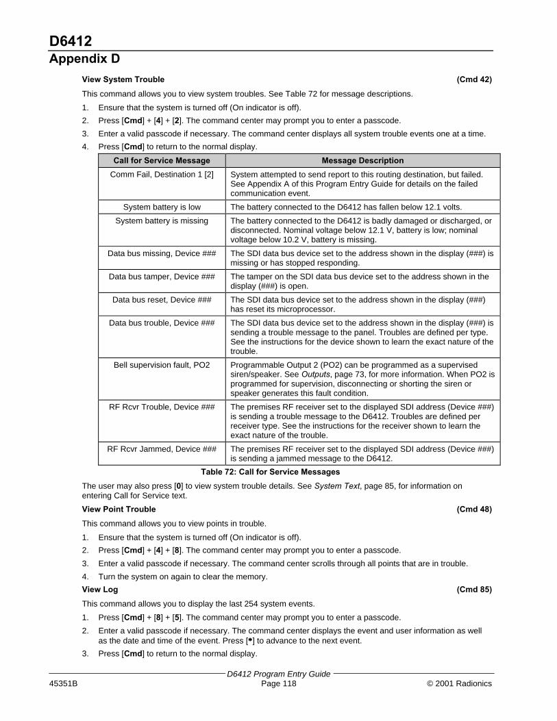
D6412Appendix D
D6412 Program Entry Guide45351B Page 118 © 2001 Radionics
View System Trouble (Cmd 42)
This command allows you to view system troubles. See Table 72 for message descriptions.
1. Ensure that the system is turned off (On indicator is off).
2. Press [Cmd] + [4] + [2]. The command center may prompt you to enter a passcode.
3. Enter a valid passcode if necessary. The command center displays all system trouble events one at a time.
4. Press [Cmd] to return to the normal display.
Call for Service Message Message Description
Comm Fail, Destination 1 [2] System attempted to send report to this routing destination, but failed.See Appendix A of this Program Entry Guide for details on the failedcommunication event.
System battery is low The battery connected to the D6412 has fallen below 12.1 volts.
System battery is missing The battery connected to the D6412 is badly damaged or discharged, ordisconnected. Nominal voltage below 12.1 V, battery is low; nominalvoltage below 10.2 V, battery is missing.
Data bus missing, Device ### The SDI data bus device set to the address shown in the display (###) ismissing or has stopped responding.
Data bus tamper, Device ### The tamper on the SDI data bus device set to the address shown in thedisplay (###) is open.
Data bus reset, Device ### The SDI data bus device set to the address shown in the display (###)has reset its microprocessor.
Data bus trouble, Device ### The SDI data bus device set to the address shown in the display (###) issending a trouble message to the panel. Troubles are defined per type.See the instructions for the device shown to learn the exact nature of thetrouble.
Bell supervision fault, PO2 Programmable Output 2 (PO2) can be programmed as a supervisedsiren/speaker. See Outputs, page 73, for more information. When PO2 isprogrammed for supervision, disconnecting or shorting the siren orspeaker generates this fault condition.
RF Rcvr Trouble, Device ### The premises RF receiver set to the displayed SDI address (Device ###)is sending a trouble message to the D6412. Troubles are defined perreceiver type. See the instructions for the receiver shown to learn theexact nature of the trouble.
RF Rcvr Jammed, Device ### The premises RF receiver set to the displayed SDI address (Device ###)is sending a jammed message to the D6412.
Table 72: Call for Service Messages
The user may also press [0] to view system trouble details. See System Text, page 85, for information onentering Call for Service text.
View Point Trouble (Cmd 48)
This command allows you to view points in trouble.
1. Ensure that the system is turned off (On indicator is off).
2. Press [Cmd] + [4] + [8]. The command center may prompt you to enter a passcode.
3. Enter a valid passcode if necessary. The command center scrolls through all points that are in trouble.
4. Turn the system on again to clear the memory.
View Log (Cmd 85)
This command allows you to display the last 254 system events.
1. Press [Cmd] + [8] + [5]. The command center may prompt you to enter a passcode.
2. Enter a valid passcode if necessary. The command center displays the event and user information as wellas the date and time of the event. Press [∗∗] to advance to the next event.
3. Press [Cmd] to return to the normal display.
D6412Appendix D
D6412 Program Entry Guide© 2001 Radionics Page 119 45351B
System Test (Cmd 41)
This command allows you to check system function by testing the system’s bell, strobe, battery and phone line.The installer determines which items can be tested. See System Test Configuration Options, page 21, for moreinformation.
1. Ensure that the system is turned off (On indicator is off).2. Press [Cmd] + [4] + [1]. The command center may prompt you to enter a passcode.
3. Enter a valid passcode if necessary. The command center begins testing the first component. A test cantake up to ten minutes.
When the tests are completed the system returns to the off state. You may quit the current test and proceedto the next one by pressing [∗∗], or you may abort the system test by pressing [Cmd].
When testing the bell and strobe, check for bell/strobe activation.
Walk Test (Cmd 44)
This command allows the user to test detection devices in the system. This should be performed weekly.
1. Ensure that the system is turned off (On light is off).2. Press [Cmd] + [4] + [4]. The command center may prompt you to enter a passcode.
3. Enter a valid passcode if necessary. The command center begins the walk test and scrolls all points to betested. You must trigger each device (Reed switch, PIR, etc.) to test it. The command center indicates thetest status of each point.
4. To stop the test, press [Cmd].
Test fire detection devices (smoke/heat detectors) weekly as instructed by the security company.
Reset the System (Cmd 47)
This command resets the system, including fire points, after an alarm. The procedure lasts approximately 20seconds.
1. Ensure that the system is turned off (On light is off).2. Press [Cmd] + [4] + [7]. The command center may prompt you to enter a passcode.
3. Enter a valid passcode if necessary. The system resets, as indicated on the display. When complete, thecommand center returns to the normal display.
Turn Watch On/Off (Cmd 61)
The Watch feature causes the system to watch specific points when the system is turned off. The D6412 alertsyou to opened doors, windows, etc.
This command turns the Watch feature on and off (see also Select Watch Tone, page 120, and Select WatchPoints, page 120).
1. Ensure that the system is turned off (On indicator is off).2. Press [Cmd] + [6] + [1]. The command center may prompt you to enter a passcode.
3. Enter a valid passcode if necessary. The command center displays the current Watch status (on or off).4. Press [1] to turn the Watch feature On, or press [2] to turn it Off.5. Press [Cmd] to exit this function.

D6412Appendix D
D6412 Program Entry Guide45351B Page 120 © 2001 Radionics
Select Watch Tone (Cmd 62)
The Watch feature causes the system to watch specific points when the system is turned off. The D6412 alertsyou to opened doors, windows, etc.
This command determines how the system responds to faulted watch points (see also Select Watch Points, page120).
1. Ensure that the system is turned off (On indicator is off).2. Press [Cmd] + [6] + [2]. The command center may prompt you to enter a passcode.
3. Enter a valid passcode if necessary. The command center displays the current Watch tone.4. Select the desired tone by pressing the appropriate corresponding key. The display indicates your selection.
Watch Tone Key Description
Off 1 Display point identity; no tone on faulted points
Short Beep 2 Display point identity; sound short tone on faulted points
Beep Till Key 3 Display point identity; sound tone till [Cmd] key is pressed
Beep Till Closed 4 Display point identity; sound tone till point returns to normal or till [Cmd] key ispressed
Table 73: Watch Tone Descriptions
5. Press [Cmd] to exit this function.Select Watch Points (Cmd 63)
After programming the system’s response to watch points (see Select Watch Tone, page 120), you mustdetermine which points the system watches. This command programs watch points. 24-hour and 24-hour Firepoints cannot be watched.
1. Ensure that the system is turned off (On indicator is off).
2. Press [Cmd] + [6] + [3]. The command center may prompt you to enter a passcode.
3. Enter a valid passcode if necessary. The command center displays all the current watch points followed byinstructions for changing the watch status.
4. Press [0] + [∗∗] to turn off all the points, or press the appropriate key followed by [∗∗] for individual points. Thedisplay scrolls the remaining points. Repeat this step to program all the desired points.
5. When complete, press [Cmd] to exit this function.
Extend Auto On Time (Cmd 51)
If entered during the Auto On Pre-alert Time, this command delays the auto-on time by one hour.
1. Ensure that the system is turned off (On light is off).
2. Press [Cmd] + [5] + [1]. The command center may prompt you to enter a passcode.
3. Enter a valid passcode if necessary. The command center displays the new time and date for the Auto-OnTime.
4. Press [Cmd] to exit this function.
Change Skeds (Cmd 52)
This command changes the time the sked turns the system on (All, Part or Part 2), off or generates an output.
1. Ensure that the system is turned off (On indicator is off).
2. Press [Cmd] + [5] + [2]. The command center may prompt you to enter a passcode.
3. Enter a valid passcode if necessary. The command center scrolls the available options.
To Change All On Skeds (see Change Skeds for Steps 1-3):
4. Press [1] and the command center scrolls the All On skeds already programmed in the system.
5. Press the number key of the sked you want to change followed by the [*] key.
6. Enter the time for the system to automatically turn All On using 24-hour format (HHMM).
7. Select the days for the system to perform this sked (Sunday = 1 through Saturday = 7, all days = 8).
8. If all days are programmed, press the [8] key to remove all days first, then press the corresponding numberkey(s) to add the desired days.

D6412Appendix D
D6412 Program Entry Guide© 2001 Radionics Page 121 45351B
To Change Part On Skeds (see Change Skeds, page 120, for Steps 1-3):
4. Press [2] and the command center scrolls the Part On skeds already programmed in the system.
5. Press the number key of the sked you want to change followed by the [*] key.
6. Enter the time for the system to automatically turn Part On using 24-hour format (HHMM).
7. Select the days for the system to perform this sked (Sunday = 1 through Saturday = 7, all days = 8).
8. If all days are programmed, press the [8] key to remove all days first, then press the corresponding numberkey(s) to add the desired days.
To Change Part 2 On Skeds (see Change Skeds, page 120, for Steps 1-3)::
4. Press [3] and the command center scrolls the Part 2 On skeds already programmed in the system.
5. Press the number key of the sked you want to change followed by the [*] key.
6. Enter the time for the system to automatically turn Part 2 On using 24-hour format (HHMM).
7. Select the days for the system to perform this sked (Sunday = 1 through Saturday = 7, all days = 8).
8. If all days are programmed, press the [8] key to remove all days first, then press the corresponding numberkey(s) to add the desired days.
To Change Off Skeds (see Change Skeds, page 120, for Steps 1-3)::
4. Press [4] and the command center scrolls all the Off skeds already programmed in the system.
5. Press the number key of the sked you want to change followed by the [*] key.
6. Enter the time for the system to automatically turn Off using 24-hour format (HHMM).
7. Select the days for the system to perform this sked (Sunday = 1 through Saturday = 7, all days = 8).
8. If all days are programmed, press the [8] key to remove all days first, then press the corresponding numberkey(s) to add the desired days.
To Change Output Skeds (see Change Skeds, page 120, for Steps 1-3)::
4. Press [5] and the command center scrolls all the Output skeds already programmed in the system.
5. Press the number key of the sked you want to change followed by the [*] key.
6. Enter the time for the system to automatically operate the output using 24-hour format (HHMM).
7. Select the days for the system to perform this sked (Sunday = 1 through Saturday = 7, all days = 8).
8. If all days are programmed, press the [8] key to remove all days first, then press the corresponding numberkey(s) to add the desired days.
Change Outputs (Cmd 54)
This command changes turns pre-programmed outputs on and off.
1. Ensure that the system is turned off (On indicator is off).
2. Press [Cmd] + [5] + [4]. The command center may prompt you to enter a passcode.
3. Enter a valid passcode if necessary. The command center displays the current status (on or off), followed byinstructions to turn the output on or off.
4. Press [0] + [∗∗] to turn off all the outputs, or press the appropriate key followed by [∗∗] for individual points. Thedisplay shows the new output status.
5. Press [Cmd] to return to the normal display.

D6412Appendix D
D6412 Program Entry Guide45351B Page 122 © 2001 Radionics
Remote Arming with Telephone, Area 1
This function controls the built-in telephone-arming feature for Area 1. When enabled, the panel answers thephone on the ring count for remote programming.
When the panel answers the phone:
− If the panel is All or Part On, it sounds three beeps and starts the handshake tone for remoteprogramming.
− If the panel is Off, it sounds one short beep followed by a 2-second pause (approximately), and thenstarts the handshake tone for remote programming (one long beep). Press and hold the [5] key* for twoseconds immediately after the first short arming beep and before the handshake tone begins.
− The panel will arm if it detects a [5] key press from the telephone (All On with Delay, faulted points areforce-armed). The panel waits three seconds, sounds three beeps (new armed state) and then hangsup.
* If arming from a cell phone, quickly press the [5] key three times. If pressing and holding the [5] key for twoseconds from a house (landline) phone does not produce a tone long enough to arm Area 1, retry by quicklypressing the [5] key three times.
Remotely disarming the panel cannot be done with a telephone.
Remote Program (Cmd 43)
This command forces the system to connect to the security company’s remote computer for programming.
1. Ensure that the system is turned off (On indicator is off).
2. Press [Cmd] + [4] + [3]. The command center may prompt you to enter a passcode.
3. Enter a valid passcode if necessary. The command center indicates remote programming in progress. Thecommand center exits this command when programming is complete.
All Areas Off (Cmd 81)
Depending on the areas assigned to the user’s authority level, this command can turn all areas off when thesystem is split into two to four areas.
1. Press [Cmd] + [8] + [1]. The command center may prompt you to enter a passcode.
2. Enter a valid passcode if necessary. The command center indicates that all areas are turned off.
All Areas On (Cmd 80)
Depending on the areas assigned to the user’s authority level, this command can turn all areas on when thesystem is split into two to four areas.
1. Press [Cmd] + [8] + [0]. The command center may prompt you to enter a passcode.
2. Enter a valid passcode if necessary. The command center indicates that all areas are turned on.
Move to Area (Cmd 50)
This command allows the user to control multiple areas from one command center when the system is split intotwo to four areas.
1. Press [Cmd] + [5] + [0]. The command center may prompt you to enter a passcode.
2. Enter a valid passcode if necessary. The command center scroll the available areas (1 to 4) followed byinstructions to press a key or press [Cmd] to exit.
Auto-Forward On Setup (Cmd 83)
This command allows the user to program the auto-forward sequence to redirect all incoming calls to a specifiedtelephone number when the system is All On.
1. Press [Cmd] + [8] + [3]. The command center may prompt you to enter a passcode.
2. Enter a valid passcode if necessary. The command center scrolls directions for entering digits for Auto-Forward On.
3. Enter the desired sequence for auto-forwarding calls. Press and hold [Cmd] to exit.
D6412Appendix D
D6412 Program Entry Guide© 2001 Radionics Page 123 45351B
Auto-Forward Off Setup (Cmd 84)
This command allows the user to program the auto-forward sequence to cancel the redirection of all incomingcalls to a specified telephone number when the system is turned off.
1. Press [Cmd] + [8] + [4]. The command center may prompt you to enter a passcode.
2. Enter a valid passcode if necessary. The command center scrolls directions for entering digits for Auto-Forward Off.
3. Enter the auto-forward off sequence. Press and hold [Cmd] to exit.
Auto-Forward On/Off (Cmd 82)
This command turns the Auto-Forward feature on and off.
1. Press [Cmd] + [8] + [2]. The command center may prompt you to enter a passcode.
2. Enter a valid passcode if necessary. The command center displays the current status and available options.Press [1] to turn Auto-Forward On or press [2] to turn Auto-Forward Off.
3. Press [Cmd] to exit this feature.
LED Command Center
The system remembers passcodes entered for approximately 10 seconds after you have stoppedpressing keys. To log out of the system, press the [Cmd] key twice. The Cmd LED will stay outacknowledging that you have successfully logged out.
The LED Command Center lights different indicators (numbers, All, Part, etc.) on the display to indicate systemstatus. The D6412 system cannot be programmed from an LED Command Center. The command centermay have up to 21 keys that perform various functions (see Keys, page 111, under the Text Command Center,page 111).
The LED Command Center also emits various tones as described above (see Tones, page 111, under TextCommand Center, 111).
Commands
Commands allow the user to carry out various tasks (add/delete passcodes, set date/time, test the system, etc.).Commands will be indicated as follows: [Cmd] + [6] + [3]. To enter this command, press the [Cmd] key followedby the [6] key and then the [3] key.
Keypad Adjust (Cmd 49)
See Text Command Center, Keypad Adjust (Cmd 49), page 112, for instructions on adjusting the commandcenter’s keystroke volume. The display brightness cannot be adjusted on the LED Command Center.
Silence Alarms
During an alarm, the alarm tone sounds and the alarming points illuminate on the display. If a valid passcode isentered before the system dials the security company, the alarm report is cancelled.
1. Enter a valid passcode to silence the alarm and turn off the system (if it was on). If this is not done, an alarmreport is sent to the central station. To determine if an alarm was reported (and later review the points thatalarmed), see View Alarm Memory, page 117.
2. Press [Cmd] to remove the alarm message from the display.
Turn the System Off
Enter a valid passcode to turn off the system (disarm). The All or Part indicator is off.

D6412Appendix D
D6412 Program Entry Guide45351B Page 124 © 2001 Radionics
Turn the System All On (Cmd 1)
This function turns the entire system on.
1. Make sure all points are normal (not faulted).
2. Press [All On]. If required, enter a valid passcode.
3. Exit Delay begins if all points are normal. Leave the premises during this time. If the system has a faultedpoint, either close it or bypass it (see Bypass Points, page 115).During Exit Delay, you may stop the system from turning on by entering a valid passcode. If you wish tobypass points, press [Bypass]; you may skip the delay by pressing [No Delay]; or you may turn the systemPart On by pressing [Part On].
4. During the last 10 seconds of Exit Delay, the command center allows for a “last chance” response to disarmthe system. During this time, the command center emits a double tone every second. The system then turnsAll On.
5. To turn the system off, enter a valid passcode.
Turn the System Part On (Cmd 2)
This function turns on part of the system, leaving the rest of the system Off.
1. Make sure all points are normal (not faulted).
2. Press [Part On]. If all Part points are normal, the Exit Delay time starts. If there are faulted points, returnthem to normal or bypass them. The command center may prompt you to enter a passcode by flashing theCmd indicator.
3. Enter a valid passcode if necessary. During Exit Delay, you may stop the system from turning on by enteringa valid passcode. If you wish to turn the system Part On with No Delay, press [No Delay], or you maybypass points by pressing [Bypass].
4. During the last 10 seconds of Exit Delay, the command center allows for a “last chance” response to disarmthe system. During this time, the command center emits a double tone every second. The system then turnsPart On.
5. To turn the system off, enter a valid passcode.
Turn the System Part 2 On (Cmd 3)
This command turns on part of the system, leaving the rest of the system Off (see Set Part 2 Points, page 124).
1. Make sure all points are normal (not faulted).
2. Press [Cmd] + [3] to turn the system Part 2 On. The command center may prompt you to enter a passcodeby flashing the Cmd light.
3. Enter a valid passcode if necessary. During Exit Delay, you may stop the system from turning on by enteringa valid passcode. If you wish to turn the system Part 2 On with No Delay, press [No Delay], or you maybypass points by pressing [Bypass].
4. During the last 10 seconds of Exit Delay, the command center allows for a “last chance” response to disarmthe system. During this time, the command center emits a double tone every second. The system then turnsPart 2 On.
5. To turn the system off, enter a valid passcode.
Set Part 2 Points (Cmd 65)
1. Make sure the system is turned off (All and Part are off).
2. Press [Cmd] + [6] + [5]. The command center may prompt you to enter a passcode by flashing the Cmdlight.
3. Enter a valid passcode if necessary. The command center display turns points already assigned for Part 2on steady. Flashing points are available for Part 2 assignment.
4. Enter the Point Number (1 through 40) and press [∗∗] to toggle it Yes or No for Part 2 (Yes = Active, ready todetect intrusion / No = Non-active, you can move freely without sounding an alarm). Repeat this procedureuntil all the desired points are selected for Part 2.
5. Press [Cmd] to exit this function.

D6412Appendix D
D6412 Program Entry Guide© 2001 Radionics Page 125 45351B
Turn the System On with No Delay
See Text Command Center, Turn the System On with No Delay, page 113, for steps to perform this command.The command center lights All or Part when the system is on.
Turn the System On with No Exit Tone
See Text Command Center, Turn the System On with No Exit Tone, page 114, for steps to perform thiscommand.
Turn the System On with Points Faulted (Bypass Points, Force Arm)
See Text Command Center, Turn the System On with Points Faulted (Bypass Points, Force Arm), page 114, forsteps to perform this command.
Bypass Points
This command allows you to bypass one or more points before turning the system All On, Part On or Part 2 On.Bypassed points can be accessed when the system is turned on without causing an alarm.
See Text Command Center, Bypass Points, page 125, for steps to perform this command. Bypassed points flashon the display.
Date and Time (Cmd 45)
See Text Command Center, Date and Time, page 115, for steps to perform this command. The display lights adigit to represent each entry (for example, points 1 through 6 light for each entry in the date and points 1 though4 light for each entry in the time).
Change Passcodes (Cmd 55)
See Text Command Center, Change Passcodes, page 115, for steps to perform this command.
Change Other Passcodes (Cmd 56)
This command allows users with the applicable authority level to change passcodes for each user in the system.See Text Command Center, Change Other Passcodes, page 115, for steps to perform this command.
Change Other’s Passcode Level (Cmd 56)
This command allows users with the applicable authority level to change passcode authority levels for each userin the system. You cannot change your own passcode authority level. See Text Command Center, ChangeOther’s Passcode Level, page 116, for steps to perform this command.
Add a Passcode (Cmd 56)
This command allows users with the applicable authority level to add new passcodes to the system. See TextCommand Center, Add a Passcode, page 116, for steps to perform this command.
Delete Passcodes (Cmd 58)
This command allows users with the applicable authority level to delete passcodes. You cannot delete your ownpasscode. See Text Command Center, Delete Passcodes, page 116, for steps to perform this command.
Renew One-time Passcodes (Cmd 53)
One-time passcodes are able to turn off the system once and then expire. This command allows users with theapplicable authority level to renew the passcode once it’s been used. See Text Command Center, Renew One-time Passcodes, page 117, for steps to perform this command.

D6412Appendix D
D6412 Program Entry Guide45351B Page 126 © 2001 Radionics
Check System Troubles (Cmd 4)
1. Make sure the system is turned off (All and Part are off).
2. Press [Cmd] + [4]
Point # Trouble Condition Description
2 System Trouble Press [2] to determine the specific trouble. See Viewing System Trouble,page 126.
3 Remote ProgramSession Active
The security company is connected to the system via the telephone line.
1 Weekly Test Due Weekly system test must be performed. Press [1] to start the test. SeeSystem Test, page 127.
5 Date and Time Lost Press [5] to set the date and time.
6 Running on BatteryOnly
Power to the system is disconnected or failed.
8 Point Trouble Press [8] to see point trouble. See Viewing Point Trouble, page 127.
10 Alarm Memory Press [0] to view previous alarms.
Table 74: LED Command Center System Trouble Descriptions
3. Press [Cmd] to exit this command.
View Alarm Memory (Cmd 40)
1. Make sure the system is turned off (All and Part are off).
2. Press [Cmd] + [4] + [0]. The command center displays all the points in alarm memory one at a time. If thepoint indicator is flashing rapidly, the alarm was transmitted to the security company. If the point flashesslowly, a cancel report followed the alarm report. If the point comes on steady, the alarm was aborted andno reports were sent.
3. To clear the alarm memory, turn the system on.
Viewing System Trouble (Cmd 42)
1. Make sure the system is turned off (All and Part are off).
2. Press [Cmd] + [4] + [2]. The command center may prompt you to enter a passcode by flashing the Cmdlight.
3. Enter a valid passcode if necessary. The command center displays the current system trouble events bylighting the point indicators.
Number Point Indicator Description
On Telephone Line Fail
Flashing Slow Comm Fail, Destination 1
1
Flashing Fast Comm Fail, Destination 2
2 On Alternate Comm Trouble
3 On Standby Jumper Closed
On Backup Battery Low4
Flashing Slow Backup Battery Missing
5 On Bell Supervision Fail
On RF Receiver Jammer6
Flashing Slow RF Receiver Trouble
On Data Bus Device Missing
Flashing Slow Data Bus Device Tamper
7
Flashing Fast Data Bus Device Trouble/Reset
On System Fault8
Flashing Slow Service Interval
Table 75: Point Indicator Descriptions
4. Press [Cmd] to return to the off state.

D6412Appendix D
D6412 Program Entry Guide© 2001 Radionics Page 127 45351B
View Point Trouble (Cmd 48)
1. Make sure the system is turned off (All and Part are off).
2. Press [Cmd] + [4] + [8]. The command center may prompt you to enter a passcode by flashing the Cmdindicator.
3. Enter a valid passcode if necessary. The command center displays all points in trouble one at a time.
Point # Trouble Condition
Off No Point Trouble
On Wiring Fault
Flashing Slow RF Sensor Low Battery
Flashing Fast RF Sensor Missing
Table 76: Point Number Trouble Conditions
4. Press [Cmd] to return to the off-state.
System Test (Cmd 41)
See Text Command Center, System Test, page 119, for steps to perform this command.
The command center lights the follow points during different test.
Point # Testing
1 Bell
2 Strobe
3 Backup Battery (up to 4 min.)
4 Communications (up to 10 min.)
Table 77: System Test Light Descriptions
The testing progress is indicated by the flash rate of the point indicator.
Point Testing
Flashing Slow Test underway
Flashing Fast Test failed
On Steady Testing complete
Table 78: System Test Point Indicators
Walk Test (Cmd 44)
See Text Command Center, Walk Test, page 119, for steps to perform this command. Press [∗∗] to exit the walktest.
Reset the System (Cmd 47)
See Text Command Center, Reset the System, page 119, for steps to perform this command.
Turn Watch On/Off (Cmd 61)
See Text Command Center, Turn Watch On/Off, page 119, for steps to perform this command. Entering Cmd 61and a valid passcode toggles the Watch feature On and Off. When Watch is turned off, the command centeremits 3 beeps. When Watch is turned on, the command center emits 1 beep.
Select Watch Tone (Cmd 62)
See Text Command Center, Select Watch Tone, page 120, for steps to perform this command.
Select Watch Points (Cmd 63)
See Text Command Center, Select Watch Points, page 120, for steps to perform this command. Watched pointscome on steady and points available to watch flash on the display.
Extend Auto On Time (Cmd 51)
See Text Command Center, Extend Auto On Time, page 120, for steps to perform this command.
All Areas On (Cmd 80)
Enter [Cmd] + [8] + [0] plus a valid passcode to turn all areas on.
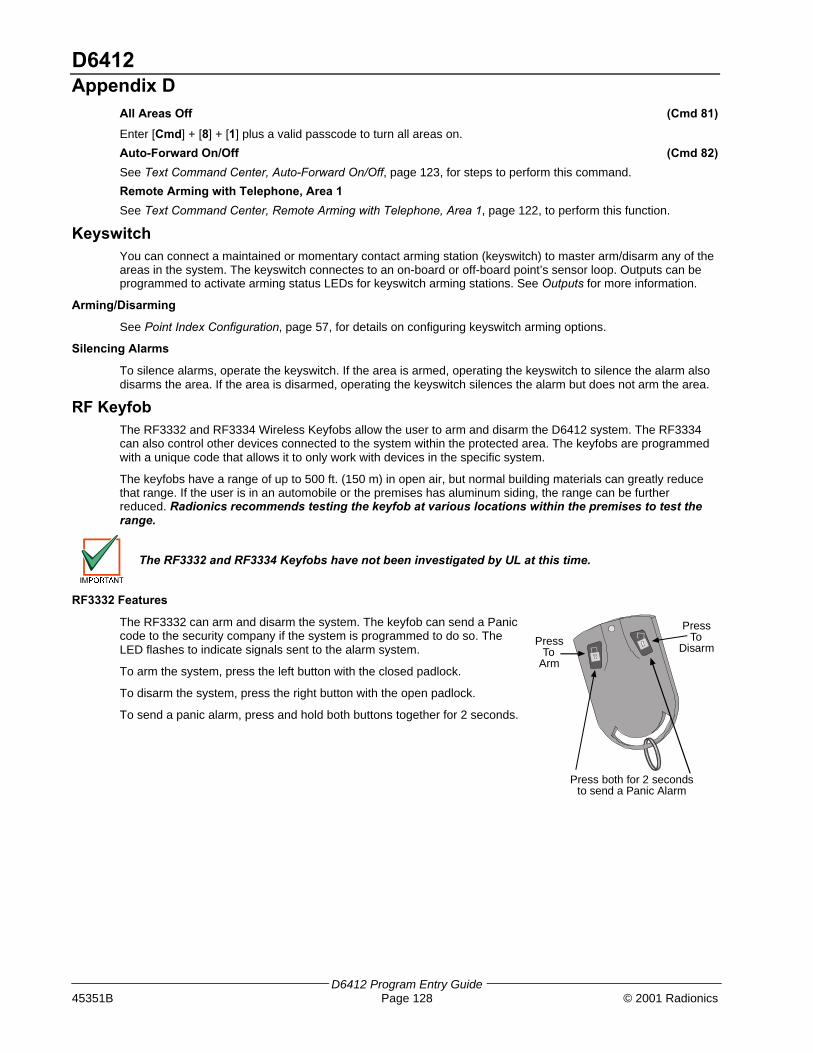
D6412Appendix D
D6412 Program Entry Guide45351B Page 128 © 2001 Radionics
All Areas Off (Cmd 81)
Enter [Cmd] + [8] + [1] plus a valid passcode to turn all areas on.
Auto-Forward On/Off (Cmd 82)
See Text Command Center, Auto-Forward On/Off, page 123, for steps to perform this command.
Remote Arming with Telephone, Area 1
See Text Command Center, Remote Arming with Telephone, Area 1, page 122, to perform this function.
KeyswitchYou can connect a maintained or momentary contact arming station (keyswitch) to master arm/disarm any of theareas in the system. The keyswitch connectes to an on-board or off-board point’s sensor loop. Outputs can beprogrammed to activate arming status LEDs for keyswitch arming stations. See Outputs for more information.
Arming/Disarming
See Point Index Configuration, page 57, for details on configuring keyswitch arming options.
Silencing Alarms
To silence alarms, operate the keyswitch. If the area is armed, operating the keyswitch to silence the alarm alsodisarms the area. If the area is disarmed, operating the keyswitch silences the alarm but does not arm the area.
RF KeyfobThe RF3332 and RF3334 Wireless Keyfobs allow the user to arm and disarm the D6412 system. The RF3334can also control other devices connected to the system within the protected area. The keyfobs are programmedwith a unique code that allows it to only work with devices in the specific system.
The keyfobs have a range of up to 500 ft. (150 m) in open air, but normal building materials can greatly reducethat range. If the user is in an automobile or the premises has aluminum siding, the range can be furtherreduced. Radionics recommends testing the keyfob at various locations within the premises to test therange.
The RF3332 and RF3334 Keyfobs have not been investigated by UL at this time.
RF3332 Features
The RF3332 can arm and disarm the system. The keyfob can send a Paniccode to the security company if the system is programmed to do so. TheLED flashes to indicate signals sent to the alarm system.
To arm the system, press the left button with the closed padlock.
To disarm the system, press the right button with the open padlock.
To send a panic alarm, press and hold both buttons together for 2 seconds.
PressTo
Arm
PressTo
Disarm
Press both for 2 secondsto send a Panic Alarm
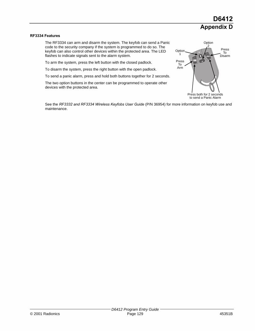
D6412Appendix D
D6412 Program Entry Guide© 2001 Radionics Page 129 45351B
RF3334 Features
The RF3334 can arm and disarm the system. The keyfob can send a Paniccode to the security company if the system is programmed to do so. Thekeyfob can also control other devices within the protected area. The LEDflashes to indicate signals sent to the alarm system.
To arm the system, press the left button with the closed padlock.
To disarm the system, press the right button with the open padlock.
To send a panic alarm, press and hold both buttons together for 2 seconds.
The two option buttons in the center can be programmed to operate otherdevices with the protected area.
PressTo
Arm
PressTo
Disarm
Option1
Option2
Press both for 2 secondsto send a Panic Alarm
See the RF3332 and RF3334 Wireless Keyfobs User Guide (P/N 36954) for more information on keyfob use andmaintenance.

D6412Appendix E
D6412 Program Entry Guide45351B Page 130 © 2001 Radionics
Appendix E: Programming from a Text Command Center
A Text Command Center set to Address 0 can be used for keypad programming. The Installer Switchmust be closed.
Press the [Cmd] key when the Text Command Center display prompts you to press the “#” key.
Installer Mode First1. Close the Installer Switch.
2. Enter the Installer Passcode (default is 6 5 4 3).
3. Press [Cmd] + [4] [1]
4. Press [8] to enter programming mode. The command center displays Radionics D6412 Revision####. for three seconds, then shows Nib:0000 D=0. At this point you are ready to begin programmingNibbles.
If the D6412 is armed, you can only enter Programming Mode from the Installer’s Keypad (KeypadAddress 0).
Programming ModeViewing Nibbles
Each parameter described in this guide is composed of one or more Nibbles and each Nibble has its ownnumber.
For example, the display may show Nib:0000 D=0. The Nib: 0000 indicates which Nibble you are at (in thiscase, Nibble 0000 which is the first digit of the Phone Number 1 for Destination 1 parameter). The second part ofthe display, D=0, indicates the value (data) that is currently set for that Nibble.
Going Direct
To view a specific Nibble, enter the Nibble number. You must enter the Nibble as a four-digit number. Forexample, to go to Nibble 0221, enter 0221. The digits entered appear in the second line of the display.
Press [Cmd] to enter the Nibble value and go to that Nibble. In this case the display will show Nib:0221 D=1.The display is now showing the Nibble and value for the desired Nibble.
Scrolling
To scroll through the Nibbles, press the [Cmd] key to move forward and press the [∗] key to move backward.
Editing Nibble Data
To change the value set for a Nibble, go to the desired Nibble by either going directly to it or scrolling through theNibbles to reach the desired one.
When the desired Nibble appears on the display, you will see the current value for that Nibble. To change it,simply enter the new value. You’ll see the new value appear on the second line of the display.
Press the [∗∗] key to accept the new value. The display changes to show the new value.
Incorrect Nibble Entries
If you make an error entering a Nibble value, press the [Cmd] key once. Then reenter the Nibble number youwish to configure and enter the correct value followed by the [∗∗] key.

D6412Appendix E
D6412 Program Entry Guide© 2001 Radionics Page 131 45351B
Programming Text Nibbles
All text parameters accommodate 16 characters of text with each character occupying two Nibbles. When a textNibble is selected, the panel goes into a special text-programming mode. When you enter the text-programmingmode, you are automatically positioned to enter the first character of the text.
In text-programming mode the command center keys take on different characters (see Table 79). Press the keysrepeatedly to scroll to the desired character.
# of Key Presses for each Character
Key 1 2 3 4 5 6 7 8 9
1 . , ? ! - & < > 1
2 A B C a b c 2 ‘
3 D E F d e f 3
4 G H I g h i 4
5 J K L j k l 5
6 M N O m n o 6
7 P Q R S p q r s 7
8 T U V t u v 8
9 W X Y Z w x y z 9
0 → _ @ # $ % * 0
* Moves to the Nibble before the text block.
Cmd Moves to the Nibble after the text block.
A Moves the cursor to the previous characterposition in the text block.
B No Function – emits single tone when pressed.
C Moves the cursor to the next character positionin the text block.
All On, Part On, No Delay and Bypass keys all produce anerror tone when pressed. Not used in text programming.
Table 79: Key/Character Assignments
Exiting Programming Mode
To exit Programming Mode, press and hold the [Cmd] key and open the Installer Switch (if necessary).
Press the [0] key once toclear a character spaceor enter a blank space.
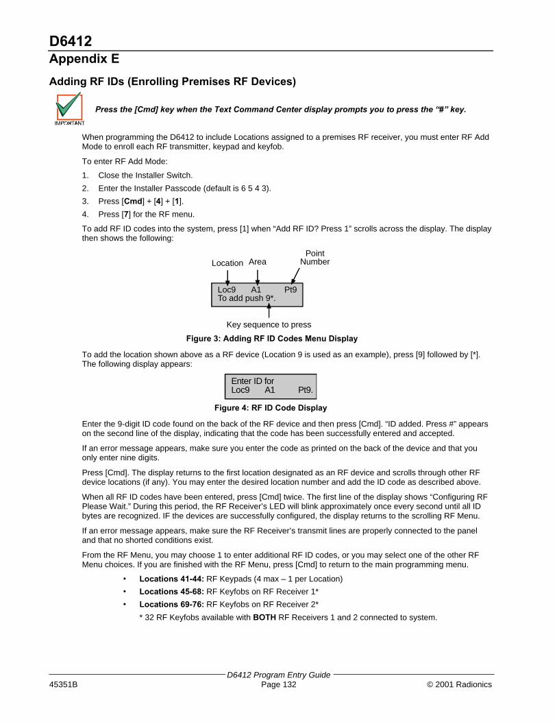
D6412Appendix E
D6412 Program Entry Guide45351B Page 132 © 2001 Radionics
Adding RF IDs (Enrolling Premises RF Devices)
Press the [Cmd] key when the Text Command Center display prompts you to press the “#” key.
When programming the D6412 to include Locations assigned to a premises RF receiver, you must enter RF AddMode to enroll each RF transmitter, keypad and keyfob.
To enter RF Add Mode:
1. Close the Installer Switch.
2. Enter the Installer Passcode (default is 6 5 4 3).
3. Press [Cmd] + [4] + [1].
4. Press [7] for the RF menu.
To add RF ID codes into the system, press [1] when “Add RF ID? Press 1” scrolls across the display. The displaythen shows the following:
Loc9 A1 Pt9To add push 9*.
Location AreaPoint
Number
Key sequence to press
Figure 3: Adding RF ID Codes Menu Display
To add the location shown above as a RF device (Location 9 is used as an example), press [9] followed by [*].The following display appears:
Enter ID forLoc9 A1 Pt9.
Figure 4: RF ID Code Display
Enter the 9-digit ID code found on the back of the RF device and then press [Cmd]. “ID added. Press #” appearson the second line of the display, indicating that the code has been successfully entered and accepted.
If an error message appears, make sure you enter the code as printed on the back of the device and that youonly enter nine digits.
Press [Cmd]. The display returns to the first location designated as an RF device and scrolls through other RFdevice locations (if any). You may enter the desired location number and add the ID code as described above.
When all RF ID codes have been entered, press [Cmd] twice. The first line of the display shows “Configuring RFPlease Wait.” During this period, the RF Receiver’s LED will blink approximately once every second until all IDbytes are recognized. IF the devices are successfully configured, the display returns to the scrolling RF Menu.
If an error message appears, make sure the RF Receiver’s transmit lines are properly connected to the paneland that no shorted conditions exist.
From the RF Menu, you may choose 1 to enter additional RF ID codes, or you may select one of the other RFMenu choices. If you are finished with the RF Menu, press [Cmd] to return to the main programming menu.
• Locations 41-44: RF Keypads (4 max – 1 per Location)
• Locations 45-68: RF Keyfobs on RF Receiver 1*
• Locations 69-76: RF Keyfobs on RF Receiver 2*
* 32 RF Keyfobs available with BOTH RF Receivers 1 and 2 connected to system.

D6412Appendix E
D6412 Program Entry Guide© 2001 Radionics Page 133 45351B
Testing RF DevicesTo test RF devices, press [2] when “Test RF Devices? Press 2” scrolls across the display. The display thenshows the following:
Loc9 A1 Pt9Test? Press 9*.
Location AreaPoint
Number
Key sequence to press
Figure 5: Test RF Devices Display
The display scrolls through all of the properly configured devices (the figure above shows Location 9 as anexample) and asks whether you wish to test. Using Location 9 as an example, press [9] followed by [*] to test theRF device at Location 9. The first line of the display shows “Activate device!”, indicating that the device must beactivated in order to test it. Once the device is activated, the following display appears:
L03 M01 P08Loc9 A1 Pt9
Figure 6: RF Device Test Status Display
The first line in the figure above shows the RF device’s test status:
− L03: System recognizes the device and the device is operating properly. Other status displays include:
− L02: System recognizes device and device operation is fair.
− L01: The device must be relocated for proper operation.
− M01: Counts the number of device activations. For example, the device being tested is a RF3401 PointTransmitter. When the magnetic assembly is removed from the point transmitter base, the activationcounter counts one activation. When the magnetic assembly is returned to the point transmitter base,the counter a second activation. Opening and closing the point transmitter’s case are also counted asactivations.
− P08: Message packet transmission.
− Alarm, Panic and Restoral messages are transmitted with 8 packets (Alarm and Restoralrefer to the transitions in and out of alarm conditions).
− Supervisory and Test transmissions (smoke detectors) consist of 4 packets.
− RF keypads transmit 4 packets for all keys except the Emergency keys, which transmit 8packets.
− RF keyfobs transmit four packets for normal operation and 8 packets for Panic buttonoperation (Arm and Disarm pressed simultaneously).
RF receivers must receive 7 or 8 data packets from a transmitter in order for that transmitter to be considered“Good” (L03). When testing RF keypads or keyfobs, the Panic functions must be used, otherwise the units onlytransmit 4 packets (see packet count above). When testing the installation of a smoke unit, the test button shouldnot be used. Doing so will result in a 4-packet transmission.
When you have finished testing a device, press [Cmd]. The list of RF devices scrolls beginning with the first(lowest) location assigned to an RF device. You may select another location to test by entering the locationnumber followed by the [*] key and repeating the procedure described above. If you are finished testing, press[Cmd] again and the RF Menu is displayed.

D6412Appendix E
D6412 Program Entry Guide45351B Page 134 © 2001 Radionics
Viewing/Removing RF ID CodesTo view or remove RF ID codes, press [3] when “View or Remove RF ID? Press 3” scrolls across the display.The display then scrolls through the properly configured RF devices:
Loc9 A1 Pt9ID: XXXXXXXXX
Location AreaPoint
Number
ID Code (see back of device)
Figure 7: RF ID Code
After each ID code is shown, the display toggles to the following message before moving to the next ID code: “Toremove ID press 9* (the number “9” represents the location number and is used as an example here and in thefigure above).
To remove the ID code, press the number key(s) that corresponds with the location number (for this example,[9]). Then press [*]. The display then asks you to confirm your removal. Press the appropriate number key(s)followed by [*]. The display then shows “Removed ID” on the first line with the location, are and point numbers ofthe removed ID on the second line.
If you wish to remove additional ID codes, press [Cmd]. The scrolling list of RF devices returns. Press[Cmd]again to return to the RF Menu when you have finished removing all ID codes. Pressing [Cmd] a third timereturns you to the main programming menu.
RF Transmitters and Point StatesAll RF transmitters with the exception of the Door/Window transmitter show only two point states: Normal andShorted.
When you assign a location to an RF point expander, the Door/Window transmitter (RF3401) has the ability tomonitor both a reed switch (magnet) and a supervised sensor loop. The D6412 automatically monitors either ofthe two or both.
The D6412 ignores the status of both the reed switch and the sensor loop until it sees a normal condition oneither.
When a location is assigned to a RF point expander, the door/window transmitter (RF3401)has the ability to monitor both a reed switch (magnet) and a supervised sensor loop. Afterthe ID for a door/window transmitter is added, the D6412 shows the status for the point asnormal. If the first message from the transmitter is “no magnet and open loop,” the D6412reports the point as faulted. If a “normal magnet” message is received, the magnet issupervised. If a “normal loop” message is received, the loop is supervised.
For example, after you add the ID for a door/window transmitter, the panel will show the status for the point asnormal even though both the reed switch and sensor loop are faulted. If the door/window transmitter is mountedon a doorjamb and its magnet is on the door, closing the door places the magnet next to the reed switch and thepoint reports a normal state. From this point forward the point will appear as faulted whenever the reed switchseparates from the magnet (reed switch is faulted). It will show the point as normal when the reed switch returnsto normal even though the sensor loop remains faulted.
Continuing this example, a contact is mounted on a window near the door. The contact and EOL resistor arewired into the door/window transmitter’s sensor loop and the window is closed. The panel now sees the sensorloop in a normal state (not faulted). From this point forward it will show the point as faulted whenever it seeseither the sensor loop or reed switch faulted. It will only show the point as normal when both the reed switch andthe sensor loop return to normal.
When the reed switch only is monitored, only the Normal and Shorted point states are shown. When both thereed switch and the sensor loop are monitored, only the Normal and Shorted point states are shown. When thesensor loop only is monitored, Normal, Shorted and Open point states are shown.
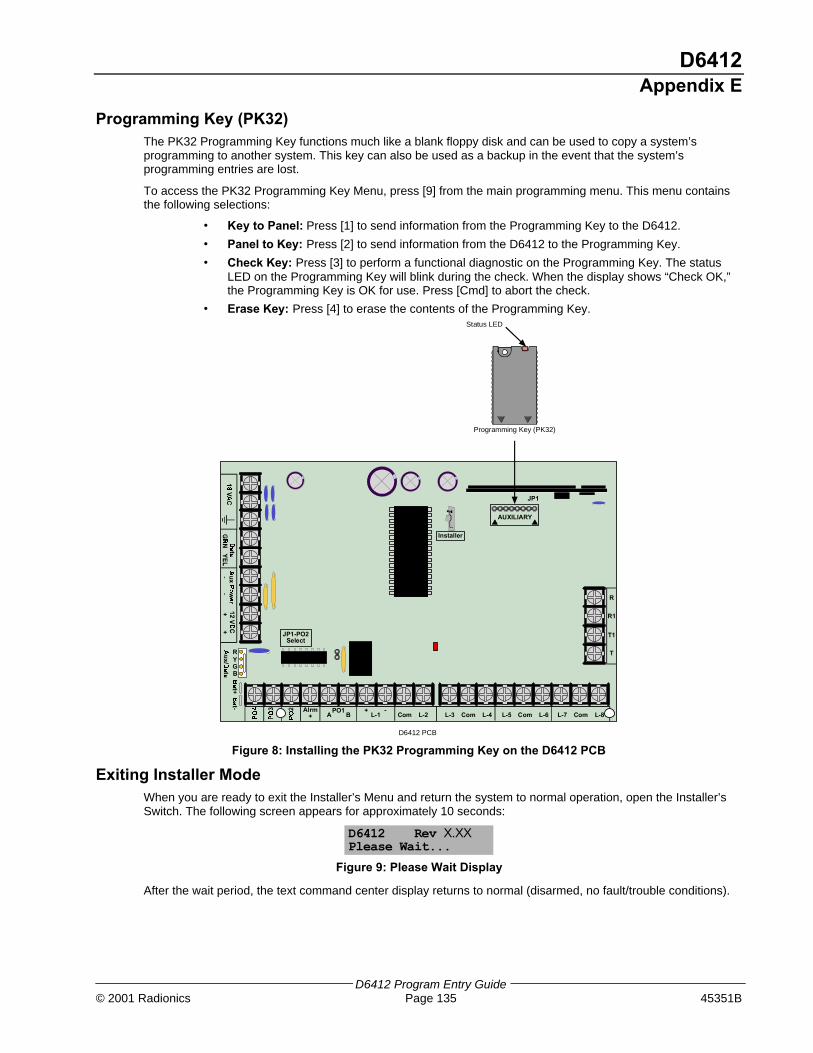
D6412Appendix E
D6412 Program Entry Guide© 2001 Radionics Page 135 45351B
Programming Key (PK32)The PK32 Programming Key functions much like a blank floppy disk and can be used to copy a system’sprogramming to another system. This key can also be used as a backup in the event that the system’sprogramming entries are lost.
To access the PK32 Programming Key Menu, press [9] from the main programming menu. This menu containsthe following selections:
• Key to Panel: Press [1] to send information from the Programming Key to the D6412.
• Panel to Key: Press [2] to send information from the D6412 to the Programming Key.
• Check Key: Press [3] to perform a functional diagnostic on the Programming Key. The statusLED on the Programming Key will blink during the check. When the display shows “Check OK,”the Programming Key is OK for use. Press [Cmd] to abort the check.
• Erase Key: Press [4] to erase the contents of the Programming Key.
RYGB
Alrm+
PO1A B L-1
+ -L-2Com L-4ComL-3 L-6ComL-5 L-8ComL-7
T
T1
R1
R
AUXILIARY
JP1
Installer
JP1-PO2Select
Programming Key (PK32)
Status LED
D6412 PCB
Figure 8: Installing the PK32 Programming Key on the D6412 PCB
Exiting Installer ModeWhen you are ready to exit the Installer’s Menu and return the system to normal operation, open the Installer’sSwitch. The following screen appears for approximately 10 seconds:
D6412 Rev X.XXPlease Wait...
Figure 9: Please Wait Display
After the wait period, the text command center display returns to normal (disarmed, no fault/trouble conditions).

D6412Appendix F
D6412 Program Entry Guide45351B Page 136 © 2001 Radionics
Appendix F: RAM IV and LogLog
The Log can store up to 254 events. When it reaches 75% full, the panel sends a Log Threshold [85] report.When the D6412 Log reaches capacity, the system sends a Log Overflow [84] report to the security company.
RAM IV can accept a download from the D6412 Log, thus clearing the log file. If the log is not cleared it beginswriting over previous events.
The first line of the log shows the event description (see Appendix B: Panel Event and Reporting Formats). Thesecond line of the log display alternates between the time and date of the event and the area, point (device),user and communication information for the event. The panel displays time in 24-hour format and the date inMM/DD/YY format.
To view the log, press [Cmd] + [8] + [5]. The Command Center may prompt you to enter a valid passcode. Pressthe [*] key to advance to the next event. Press [Cmd] to exit the log and return to the Off state.
Area, Point/Device/Line, User, Communication Data
The log employs the following characters to communicate certain information.
Display Description
A# Area Number
Pt## Point Number
Dv### Device Number
Ln## Phone Line Number
Mn# Minutes till Auto Arm Sked
U## User Number
## Communication Status for Routing Destinations 1 and 2
- (dash) Destination Disabled
A Aborted
D Deleted from Pending Buffer by Panel Reset
F Failed
L Local
P Pending
S Sent
Table 80: Log Display Descriptions
Figure 10 is a Text Command Center display of an event log. The first line describes the event and the secondline alternates between event specific information (such as area # and point #, if applicable) and the time anddate of the event.
Sensor Mon Rstl08:29 06/13/01
Event
Time of Event Date of Event
Sensor Mon RstlA1 Pt3 SL
Event
Destination 1Destination 2Event Specific
Information
Figure 10: Log Display
D6412Index
D6412 Program Entry Guide© 2001 Radionics Page 137 45351B
Index
[[A] Key Alarm Response
Emergency Alarm .................................................... 47Fire Alarm ................................................................ 47Panic Alarm ............................................................. 47
AA B C Key and Duress Reporting................................ 50A B C Keys.................................................................. 47A, B, C Keys
[A] Key Alarm Response.......................................... 47[A] Key Area Option................................................. 47[B] Key Alarm Response.......................................... 48[B] Key Area Option................................................. 47[C] Key Alarm Response ......................................... 48[C] Key Area Option................................................. 48Alarm Output Option................................................ 48Report & Ack Beep Option....................................... 49
AC Fail, Low Battery Report Options .......................... 17AC Power Supervision Options
AC Fail Report is Tag-along .................................... 16Disable AC Fail Local Annunciation......................... 16Enable Arm/Disarm/Bypass Tracking ...................... 16Enable Internal Crystal to Keep Time ...................... 16
Ack Wait Time ............................................................. 16Alarm Event Abort Window ......................................... 69Alarm Output Volume.................................................. 71Alternate Communication Path...................................... 9Answering Machine Bypass ........................................ 13Area 1
Idle Text ................................................................... 86Name....................................................................... 86
Area 2Idle Text ................................................................... 86Name....................................................................... 86
Area 3Idle Text ................................................................... 86Name....................................................................... 86
Area 4Idle Text ................................................................... 86Name....................................................................... 86
Area Data .................................................................. 136Area Option, User # .................................................... 44Area Text..................................................................... 86Areas........................................................................... 33
Area # Account Number for Routing Destination 1 .. 33Area # Account Number for Routing Destination 2 .. 34Area # Opening/Closing Reporting Options............. 34Lock Area # Reporting ............................................. 35
Arming Options 1Answering Machine Bypass..................................... 27Enable All On – No Exit Feature.............................. 27Remote Arming with Telephone .............................. 27
Arming Options 2Enable All Areas All On ........................................... 28Enable All Areas Off ................................................ 28First Area to Open/Last Area to Close..................... 28Make Area 1 Common Area .................................... 28
Authority Level.............................................................44Authority Levels ...........................................................35
Authority Level Option 1...........................................35Authority Level Option 10.........................................39Authority Level Option 11.........................................39Authority Level Option 12.........................................39Authority Level Option 13.........................................39Authority Level Option 14.........................................39Authority Level Option 15.........................................39Authority Level Option 2...........................................36Authority Level Option 3...........................................36Authority Level Option 4...........................................36Authority Level Option 5...........................................37Authority Level Option 6...........................................37Authority Level Option 7...........................................38Authority Level Option 8...........................................38Authority Level Option 9...........................................38
Auto On Pre-Alert Time ...............................................19Auto-Forward Configuration.........................................11Automatic Test
Report Interval .........................................................24Report Options .........................................................23Test Time .................................................................24
BBell Time......................................................................71Bypass/Force-Arm Limit ..............................................28
CCall Back .....................................................................12Call for Service Interval................................................18Call for Service/System Inactive Option
Weekly Test Reminder.............................................18Call for Service/System Inactive Options.....................18Cancel Event Enabled .................................................20Comm Fail Event .........................................................95Command Center
Text ............................................................................7Command Center # Area.............................................46Command Center Options
Beep on System Trouble..........................................46Don’t Show Point Status on LEDs............................46Enable Exit Tone......................................................46
Command Centers.......................................................45LED........................................................................123Text ................................................................111, 130
Communication Data .................................................136Configuration
Auto-Forward ...........................................................11Passcode .................................................................40Phone.......................................................................11Point Index ...............................................................57RAM.........................................................................11SDI Bus Device ........................................................82
Cross Point ..................................................................63

D6412Index
D6412 Program Entry Guide45351B Page 138 © 2001 Radionics
DD624 Telephone Command Module............................84D9533 RS232 Module ...........................................83, 84Daylight Savings Time Options ...................................26Device Data...............................................................136Duress.........................................................................47Duress Reporting Options ...........................................49
EEntering Phone Numbers from the Command Center...9Entry Delay Time 1......................................................31Entry Delay Time 2......................................................31Exit Delay Time 1 ........................................................32Exit Delay Time 2 ........................................................32Exit Time Restart.........................................................30Exiting Installer Mode ................................................135
GGlobal Close................................................................27Global Open ................................................................27Global Output Configuration........................................70
Alarm Output Arming Beep Volume.........................71Bell Time..................................................................71Siren Warble Frequency ..........................................71Strobe Output Type Options ....................................72
Global Output OptionsEnable Alarm Output Arming Beep..........................70Enable Strobe Arming Flash ....................................70Output 2 Is Supervised Horn/Speaker Output..........70Send Output Set/Reset Reports ..............................70
Global Point Configuration ..........................................66Alarm Event Abort Window......................................69EOL Resistor Value .................................................66Point Response Options ..........................................66Sensor Monitor Time ...............................................68Swinger Count for Alarm Output ..............................67Swinger Count for Point Reports .............................68
Global Reporting .........................................................15Global Reporting Options
Burg Alarm After Two Failed Attempts.....................15Delay Alarm Output .................................................15Enable Handshake ..................................................15Extend Handshake ..................................................15Local Only................................................................15
Glossary ......................................................................91Groups ..........................................................................6
IInstaller Mode............................................................130Installer Passcode .................................................40, 41Installer Switch ............................................................26Installer Switch Options...............................................26
KKeyfob Options
Assign O (trapezoid) Key to Part On........................89Assign P (sun) Key to Part 2 On ..............................89Panic Enabled..........................................................89
Keypad Programming Enabled....................................26Keyswitch ..................................................................128Keyswitch Installation ..................................................62
LLED Command Center ............................................. 123Line Data .................................................................. 136Location
Location ## Point Text............................................. 87Location Text .............................................................. 87Locations .................................................................... 51
Location ##, Area .................................................... 56Location ##, Device................................................. 55Location ##, Point Index.......................................... 55Location ##, Point Number...................................... 56Sample Location Scenario ...................................... 53
Log............................................................................ 136Log Supervision Configuration.................................... 19
NNibbles.................................................................. 6, 130
Editing ................................................................... 130Going Direct .......................................................... 130Programming Text................................................. 131Scrolling ................................................................ 130Viewing.................................................................. 130
OOne Shot Modes......................................................... 78Open/Close Reporting Options ................................... 29
Exit Error ................................................................. 29Recent Closing........................................................ 29
Opening Closing Report Routing ................................ 30Options ......................................................................... 6Options 1
Alarm Event Abort ................................................... 61Armed for Part Mode............................................... 62Sensor Trouble Monitor........................................... 62Voice Verification .................................................... 61
Options 2Alarm Output ........................................................... 63Can Be Bypassed or Force Armed.......................... 63Cross Point.............................................................. 63RF Transmitters and Point States ........................... 64Swinger Bypass ...................................................... 63
Outputs ....................................................................... 73Area......................................................................... 74Base........................................................................ 78Function .................................................................. 74Mode ....................................................................... 77Multiplier.................................................................. 78

D6412Index
D6412 Program Entry Guide© 2001 Radionics Page 139 45351B
PPager Format ............................................................ 107Pager Reports ........................................................... 107Panel Event97, 98, 99, 100, 101, 102, 103, 104, 105,
106Parameters.................................................................... 6Passcode Configuration .............................................. 40Passcodes................................................................... 44
Installer .............................................................. 40, 41Length...................................................................... 40
Phone Configuration ................................................... 11Call Forwarding Auto Off Digits ............................... 12Call Forwarding Auto On Digits ............................... 11DTMF/Pulse Dialing................................................. 11Phone Line Fault Response Options ....................... 14RAM Answer Ring Count, Answering Machine Bypass
............................................................................. 13RAM Passcode........................................................ 13Remote Programming Call Back Phone Number .... 12
Phone Line Fault Response OptionsBurg Alarm & Strobe Functions, All or Part On........ 14Burg Alarm & Strobe Functions, Off ........................ 14No Phone Line Supervision ..................................... 14Trouble at Command Center ................................... 14
PK32 (Programming Key) Enabled ............................. 26Point Data ................................................................. 136Point Index
Alarm Report ........................................................... 65Options 1 ..................................................... 46, 61, 86Options 2 ................................................................. 63Point Type ............................................................... 57Pulse Count ............................................................. 60Pulse Count Time .................................................... 60Response Options ................................................... 64Restoral Report ....................................................... 65
Point Index Configuration ............................................ 57Point Response Options
Entry Delay .............................................................. 67Smart Swinger ......................................................... 66Unverified Events Send Trouble Reports................. 66
Point States............................................................... 134Premises RF Receiver
Receiver Options ..................................................... 82Supervision Interval ................................................. 82
ProgrammingCommand Center ...................................................... 7RAM IV ...................................................................... 7
Programming Key (PK32) ......................................... 135Programming Mode................................................... 130
Exiting.................................................................... 131Programming Options ................................................. 25Programming Parameters ............................................. 8Pulse Count Time
Off-board Points ...................................................... 60Pulse Modes ............................................................... 78
RRAM Configuration ......................................................11RAM IV ..................................................................7, 136Remote Programming Options
Enable Remote Programming..................................25Enable Remote Programming Callback ...................25Terminate on Alarm..................................................25
Report ProgrammingAlarm........................................................................65Bypass ...............................................................67, 68Force Bypass ...........................................................67Point Trouble............................................................69Restoral....................................................................65Restoral from Trouble ..............................................69Sensor Trouble ........................................................68Swinger Bypass .......................................................68
Reporting Formats .......................................................97Response Options .......................................................64Return to Default .........................................................90Return to Defaults........................................................90RF IDs .......................................................................132RF Jam Detect Level ...................................................83RF Keyfob..................................................................128RF Keyfobs..................................................................89
Keyfob Options ........................................................89Keyfob Receiver Assignment Options......................89
RF Keypad OptionsBelongs to Receiver 2 ..............................................88Supervised ...............................................................88
RF Keypads.................................................................88Area .........................................................................88Options.....................................................................88
RF Transmitters.........................................................134RF Transmitters and Point States................................55RF3332......................................................................128RF3334......................................................................129Routing ........................................................................95
Format for Destination 1 (2) .....................................10Phone Number 1 for Destination 1 (2)........................8Phone Number 2 for Destination 1 (2)........................9
Routing Destinations......................................................8Routing Dialing ............................................................95RS232 Output
GSP Format .............................................................83Log Format for Printer ..............................................83

© 2001 Radionics, a division of Detection Systems, Inc.PO Box 80012, Salinas, CA 93912-0012, USACustomer Service: (800) 538-5807
45351BProgram Entry Guide
10/01D6412
Page 140 of 140
SSample Location Scenario ..........................................53SDI Address ..............................................................110SDI Bus Device Configuration .....................................82Siren Warble................................................................71Skeds ..........................................................................79
Assign Area .............................................................80Assign Output ..........................................................80Options ....................................................................81Time.........................................................................80Type.........................................................................79
Steady and Toggle Modes ..........................................78Strobe Output ..............................................................72System Inactive Interval ..............................................18System Status Report Swinger Count .........................17System Status Reports Routing ..................................17System Test ................................................................21System Test Enable Options.......................................22System Test Options
Send Test Report.....................................................21Test Battery .............................................................21Test Bell...................................................................21Test Strobe ..............................................................21
System Text ................................................................85
TTesting RF Devices .................................................. 133Tests........................................................................... 21
Automatic Test ........................................................ 23System Test ............................................................ 21Test Report Routing ................................................ 24Walk Test .......................................................... 22, 23
Text[A] Key..................................................................... 85[B] Key..................................................................... 85[C] Key .................................................................... 85Area......................................................................... 86Call for Service........................................................ 85Location................................................................... 87System .................................................................... 85
Text Command Center ..................................7, 111, 130
UUser Data.................................................................. 136User Tamper
User Tamper Lockout Time..................................... 41User Tamper Options.............................................. 40User Tamper Retry Count ....................................... 41
Users .......................................................................... 42Authority Level ........................................................ 44Passcodes............................................................... 44
VViewing/Removing RF ID Codes .............................. 134
WWalk Test.............................................................. 22, 23
Test Start/End Report Routing ................................ 23