profibus - iai-robot.co.jp · sample programs for s7-300 ... protocol network on which a host...
TRANSCRIPT

Operation Manual, Second Edition
ProfiBus Gateway Unit RCM-GW-PR

CAUTION
Note on Connecting a PC or Teaching Pendant to the Gateway Unit Grounded via the Positive Terminal of Its 24-V Power Supply
If the positive terminal of the gateway unit’s 24-V power supply is grounded, use a SIO converter as shown below to connect a teaching pendant or PC to the gateway unit. In this case, do not connect the FG of the SIO converter.
Teaching pendant PC, etc.
PC software
RS232 connection type <Model number: RCM-101-MW> USB connection type <Model number: RCM-101-USB> * The cables are supplied with the
PC software.
SIO converter (optional) (with built-in terminal resistor) Model number: RCB-TU-SIO-A (B) Gateway unit
Do not connect the FG.
* One e-CON connector, one junction and one terminal resistor are supplied with each controller link cable.
e-CON connector (3-1473562-4 by AMP) Junction (5-1473574-4 by AMP)
Terminal resistor R = 220Ω
Controller link cable Model number: CB-RCB-CTL002
24-V power supply

CAUTION If the positive terminal of the gateway unit’s 24-V power supply is grounded, the gateway unit cannot be connected directly to a teaching pendant or PC. If a teaching pendant or PC is connected directly to the gateway unit grounded in this condition, the power-supply circuit may be shorted and the PC/teaching pendant may be damaged.
Cannot be connected directly.
This teaching pendant cannot be
used this way.
Gateway unit
24-V power supply

PfofiBus Gateway
Table of Contents
1. Overview ................................................................................................................... 1 1.1 ProfiBus Gateway Unit ................................................................................................................ 1 1.2 What Is ProfiBus? ........................................................................................................................ 2 1.3 Application Example of Gateway Unit ......................................................................................... 3 1.4 Features and Key Functions ........................................................................................................ 4
1.4.1 Features ......................................................................................................................... 4 1.4.2 Key Functions ...................................................................................................................... 4 1.5 Description of Model Name ......................................................................................................... 7 1.6 Accessories ................................................................................................................................. 7
2. Specifications and Name of Each Part ...................................................................... 8 2.1 General Specifications ................................................................................................................. 8 2.2 External Dimensions .................................................................................................................... 9 2.3 Name and Function of Each Part .............................................................................................. 10
3. Installation and Noise Elimination Measures ........................................................... 16 3.1 Installation Environment. ........................................................................................................... 16 3.2 Supply Voltage .......................................................................................................................... 16 3.3 Noise Elimination Measures and Grounding ............................................................................. 16 3.4 Installation.................................................................................................................................. 18
4. Wiring ...................................................................................................................... 19 4.1 Overall Configuration ................................................................................................................. 19 4.2 I/O Signals of Gateway Unit ...................................................................................................... 22 4.3 Design of SIO Communication Network (SIO Communication) ................................................ 25
4.3.1 Wiring ........................................................................................................................... 25 4.3.2 Axis Number Setting ..................................................................................................... 33
4.4 How to Connect the Teaching Tool When the Positive Terminal of the 24-V Power Supply Is Grounded ................................................................................................................................... 34
5. Address Configuration of Gateway Unit .................................................................. 35 5.1 Position Number Specification Mode ........................................................................................ 35
5.1.1 Overall address configuration ....................................................................................... 36 5.1.2 Gateway Control/Status Signals ................................................................................... 37 5.1.3 Assignment for Each Axis ............................................................................................ 40
5.2 Direct Numerical Specification Mode ........................................................................................ 43 5.2.1 Overall Address Configuration ..................................................................................... 44 5.2.2 Gateway Control/Status Signals ................................................................................... 46 5.2.3 Assignment for each axis ............................................................................................. 49
5.3 Command Specification Mode................................................................................................... 53 5.3.1 Overall Address Configuration ..................................................................................... 55 5.3.2 Gateway Control/Status Signals ................................................................................... 57 5.3.3 Assignment for Each Axis ............................................................................................ 60 5.3.4 Command Area ............................................................................................................ 65
6 Communication Signal Details ................................................................................ 75 6.1 Overview of Communication Signal Timings ............................................................................. 75 6.2 Communication Signals and Operation Timings ....................................................................... 77 6.3 Basic Operation Timings ........................................................................................................... 85

PfofiBus Gateway
6.4 Command Transmission ............................................................................................................ 95
7. Building Your Network System ................................................................................ 96 7.1 Procedure .................................................................................................................................. 96 7.2 Setting the Controller ................................................................................................................. 97 7.3 Setting the Gateway Unit and PLC Master ................................................................................ 99 7.4 PLC Address Assignment ........................................................................................................ 100
8. Supported S7 Function Blocks/Functions.............................................................. 106 8.1 GW_CTL_11 ............................................................................................................................ 107 8.2 RC_NVC_11 ............................................................................................................................ 108 8.3 RC_ESYNC_00 ....................................................................................................................... 109 8.4 RC_BCMOVP_00 .................................................................................................................... 110 8.5 RC_READ_00 ......................................................................................................................... 111 8.6 RC_WRITE_00 ........................................................................................................................ 112 8.7 RC_PROM_00 ......................................................................................................................... 113 8.8 RC_PMSL_00 .......................................................................................................................... 113
Appendix 1. Sample Programs for S7-300 .............................................................. 114
Appendix 2. Supply Format and Use Procedure of FB/FCt ..................................... 117


1
PfofiBus Gateway
1. Overview 1.1 ProfiBus Gateway Unit The ProfiBus Gateway Unit (hereinafter referred to as “ProfiBus Gateway” or “Gateway Unit”) is used to connect a ProfiBus communication protocol network on which a host programmable controller (hereinafter “PLC”) operates, to a SIO communication sub-network (Modbus communication protocol) linking ROBO Cylinder controllers. The physical standard to which the SIO communication network conforms is RS-485, and the slave addresses on this network are 1 through 16. All data exchanged between the ProfiBus communication network and the Modbus SIO communication network are tentatively saved in the internal memory of the Gateway Unit, and then transferred cyclically. The PLC recognizes the Gateway Unit as a remote I/O device. The Gateway Unit supports PCON-C/CG/SE, ACON-C/CG/SE, SCON-C and ERC2-NP/PN/SE controllers. * “Gateway” is a term used in communication networks, referring to a device that converts data to/from
different media and protocols to enable communication between networks. * ProfiBus protocols include ProfiBus-DP for factory automation (FA) and ProfiBus-PA for process
automation (PA). Of these two protocols, this manual covers ProfiBus-DP. Accordingly, “ProfiBus” refers to ProfiBus-DP throughout this manual.
Caution This manual only describes the controls feasible using the Gateway Unit. In the event of any conflict between this manual and the operation manual for the controller, the content of this manual will prevail. Refer to the operation manual for each controller for any function, parameter setting, alarm detail or any other information not described in this manual.

2
PfofiBus Gateway
1.2 What Is ProfiBus? (1) FA communication system
In FA communication, each communication specification varies depending on the communicating equipment, type of information, and purpose of communication, among others. In general, however, the FA communication system is divided into the information level, controller level and field level, as shown below.
(2) Information level
Also called “PLC upper network.” The main purpose of this network level is to transmit production information, etc., to information terminals. Ethernet is the most commonly used communication method for the information level.
(3) Controller level
Also called “Inter-PLC network.” This network level often handles real-time information of production lines. (4) Field level
Also called “PLC lower network.” This network level is mainly used to save wirings for systems controlled by a single controller. In this sense, this network is regarded as a means for “wire-saving communication.” The field level is largely divided into the device level and the sensor level.
Info
rmat
ion
leve
l C
ontro
ller l
evel
Fi
eld
leve
l
FA computer
Robot Remote I/O
Motor driver
Installed instrument
Solenoid valve
Limit switch
Sensor level
Device level
Key open network
3
PfofiBus Gateway
(5) ProfiBus
ProfiBus is an open field network most commonly used in the world today. It was first established under DIN 19245 (German standard) in Germany in 1989, and standardized under EN 50170 (European standard) in July 1996. In January 2000, ProfiBus became an international standard under IEC 61158. There are two ProfiBus protocols designed for different purposes: ProfiBus-DP for factory automation (FA), and ProfiBus-PA for process automation. This manual covers ProfiBus-DP. The key features of ProfiBus-DP are as follows: [1] A field network realizing complete multi-vendor connectivity [2] Able to send large amounts of data at high speed.
• Up to 244 bytes of data per device • Maximum baud rate of 12 Mbps
[3] Up to 125 nodes can be connected. * For details on ProfiBus, refer to the operation manuals for your master unit and PLC.
Along with this manual, also read the operation manual for each controller connected. This ProfiBus Gateway cannot be used in any way not described as feasible in this manual. To prevent malfunction, the customer is also advised not to use settings, wirings and other uses other than those described as feasible in this manual.
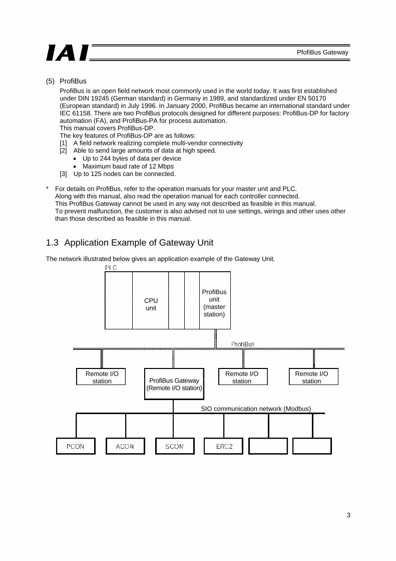
1.3 Application Example of Gateway Unit The network illustrated below gives an application example of the Gateway Unit.
CPU unit
ProfiBus unit
(master station)
Remote I/O station ProfiBus Gateway
(Remote I/O station)
Remote I/O station
Remote I/O station
SIO communication network (Modbus)

4
PfofiBus Gateway
1.4 Features and Key Functions 1.4.1 Features The ProfiBus gateway unit lets you select a desired operation mode from three modes including the position number specification mode, direct numerical specification mode and command specification mode. (1) Position number specification mode
In this mode, a desired position number is specified to operate the actuator. Up to 16 axes can be connected. The position data, speed, acceleration/deceleration, etc., must be input to the position table beforehand. Although the input/output of various status signals and completed position number can be read, the current position cannot be monitored in this mode.
(2) Direct numerical specification mode
In the direct numerical specification mode, the position data, speed, acceleration/deceleration, positioning band and push-current limiting value are specified directly as numerical values to operate the actuator. Various status signals can be input/output and current position data can be read. There are five patterns in the numerical specification mode, each accommodating a different number of connected axes. [1] Direct numerical specification mode/Up to 4 axes can be connected [2] Direct numerical specification mode/Up to 6 axes can be connected [3] Direct numerical specification mode/Up to 8 axes can be connected [4] Direct numerical specification mode/Up to 10 axes can be connected [5] Direct numerical specification mode/Up to 16 axes can be connected
(3) Command specification mode
In this mode, the actuator can be operated in one of two operation patterns: “positioner operation” in which a desired position number is specified to operate the actuator, and “simple direct operation” where only the position data is specified directly as a numerical value and all other items such as the speed, acceleration/deceleration, positioning band and push-current limiting value are specified via a position number. As for the axis configurations, these two operation patterns can be used separately or in combination. If the two patterns are combined, the axis numbers must be assigned sequentially from the axes used in positioner operation, followed by the axes used in simple direct operation. You can select the Large mode (160 input bytes, 160 output bytes), Middle mode (128 input bytes, 128 output bytes) or Small mode (64 input bytes, 64 output bytes) depending on the size of the assigned areas, and up to 16 axes can be connected.
1.4.2 Key Functions A comparison table of key functions provided by the gateway unit in the respective modes is given on the following page. Use this table as a reference in conjunction with the explanation of each operation mode in Chapter 5.

PRO
FIBUS G
ateway
Key function Position number
specification mode Direct numerical specification
mode Command specification mode
Positioner operation Simple direct operation Operation by position data specification X (P table specification) (P table rewriting) Direct specification of speed and acceleration/deceleration X (P table specification) (P table rewriting) X (P table specification)
Direct specification of positioning band X (P table specification) (P table rewriting) X (P table specification) Push-motion operation (P table specification) (P table specification) (P table specification) Operation by position number specification X X Position table enabling X Maximum number of storable position numbers 64 - 512 512
Reading of completed position number X X Selection of controller PIO pattern X X *2 X Zone (parameter) (2) X *3 X Position zone (P table) X X *4 X Reading of various status signals Speed change during movement Operation at different acceleration and deceleration (P table specification)
Monitoring of current position *5 X X
Com
man
d
Sending/receiving of commands/responses X X
Reading/writing of P table data X X X Reading of current position *6 X X Reading of alarm code X X Broadcasting X X X
Number of connectable axes 16 4 6 8 10 16 16 16 Maximum specifiable value of position data P table specification 9999.99 mm 9999.99 mm 9999.99 mm
Large mode Middle mode Small mode
Mode setting SW1 2 0 4 8 13 12 1 5 9
Gateway I/O bytes Input 48 28 40 52 64 100 160 128 64 Output 48 52 76 100 124 196 160 128 64
*1 P table: Position table *2 PIO patterns 0 to 4 can be selected. *3 PIO patterns 1 to 3 are not supported. *4 PIO pattern 3 is not supported. *5 In the current position monitoring function, the current position data is assigned to a gateway output signal.
Accordingly, the current position can be read directly from the PLC. *6 Reading the current position means reading the current position data indirectly with the PLC issuing a read command to the gateway.

6
PfofiBus Gateway
Next, the relationship of the number of positions supported by each controller under each PIO pattern, and the maximum number of positions that can be stored in the gateway unit, is explained. Take note that the number of positions may become subject to restrictions. PIO pattern (Parameter No. 25)
SE
0 1 2 3 4
ERC2
Operation type
Standard Solenoid type
Zone signal type
Position zone type -
Dedicated SIO
operation
Number of positioning points 8 3 16 16 - 64
Home return signal X X X - Maximum number of gateway positions
Zone signal X X -
P zone signal X X X -
Gat
eway
con
trol Position number
specification mode 8
*1 X 16 *1
16 *1 - 64 64
Com
man
d sp
ecifi
catio
n Positioner operation
*1 *38 (0) X *1 *3
16 (2) *1 *316 (3) - *3
64 (0) 512
Simple direct operation - X - - - - 512
PCON ACON SCON
Operation type
Positioning mode
Teaching mode
256-point mode
512-point mode
Solenoid mode 1
Dedicated SIO
operation
Number of positioning points 64 64 256 512 7 64
Home return signal Maximum number of gateway positions
Zone signal X X X
P zone signal X
Gat
eway
con
trol Position number
specification mode 64 64 256 ↓
64 *2
512 ↓
64 *2 7 64 64
Com
man
d
Com
man
d sp
ecifi
catio
n ifi
ti
Positioner operation
*3 64 (0)
*3 64 (1)
*3 256 (2)
*3 512 (3)
*3 7 (4)
*3 64 (0) 512
Simple direct operation - - - - - - 512
*1 In the operation mode based on position number specification, the number of positions is limited
according to the selected PIO pattern (parameter No. 25). (The gateway can handle more positions.) *2 Since the gateway can handle 64 positions, the number of controller positions is limited. *3 In the case of a positioner operation axes operating in the command specification mode, the PIO
pattern selection parameter of the controller must correspond to the I/O pattern set by gateway control signals PPS0 to PPS2. The numbers of positions shown in parentheses ( ) indicate values set by PPS0 to PPS2.

7
PfofiBus Gateway
1.5 Description of Model Name 1.6 Accessories [1] Power-supply input connector plug 1 pc
MC1•5/4-ST-3•5 (Phoenix Contact) [2] SIO communication connector plug 1 pc
MC1•5/6-ST-3•81 (Phoenix Contact)
Base model ProfiBus specification
Gateway Unit

8
PfofiBus Gateway
2. Specifications and Name of Each Part 2.1 General Specifications
Item Specification Power supply 24 VDC ± 10% Current consumption 300 mA max.
Pro
fiBus
spe
cific
atio
ns
Communication standard Group 2 only server Insulated node of network powered operation type
Communication specification Master-slave connection Bit strobe Polling Cyclic
Baud rate 9.6 kbps to 12 Mbps (Set automatically) Communication cable length (*1) 9.6 kbps 1500 m
500 kbps 400 m 1.5 Mbps 200 m 3 Mbps 200 m 12 Mbps 100 m
SIO
com
mun
icat
ion
spec
ifica
tions
Transmission path configuration IAI’s original multi-drop differential communication Communication method Half-duplex Synchronization method Asynchronous Transmission path type EIA RS485, 2-wire type Baud rate 230.4 kbps Error control method No parity bit, CRC (*2) Communication cable length Total cable length: 100 m max. Communication cable Double shielded twisted-pair cable
(Recommended cable: HK-SB/20276 X L, 2P X AWG22 by Taiyo Electric Wire & Cable)
Connected units 16 axes max.
Env
ironm
ent
Ambient operating temperature 0 to 40°C Ambient operating humidity 85% RH or below (non-condensing) Operating ambience Free from corrosive or flammable gases, oil mist or powder dust Storage temperature -10 to 65° C Storage humidity 90% RH or below (non-condensing) Vibration durability 4.9 m/s2 (0.5 G)
Protection class IP20 Weight 480 g or below
*1 Refer to the operation manuals for your master unit and PLC in the case of T-branch communication. *2 CRC: Cyclic Redundancy Check
A data error detection method commonly used in synchronous transmission.

9
PfofiBus Gateway
2.2 External Dimensions
(Inst
alle
d di
men
sion
)
10
PfofiBus Gateway
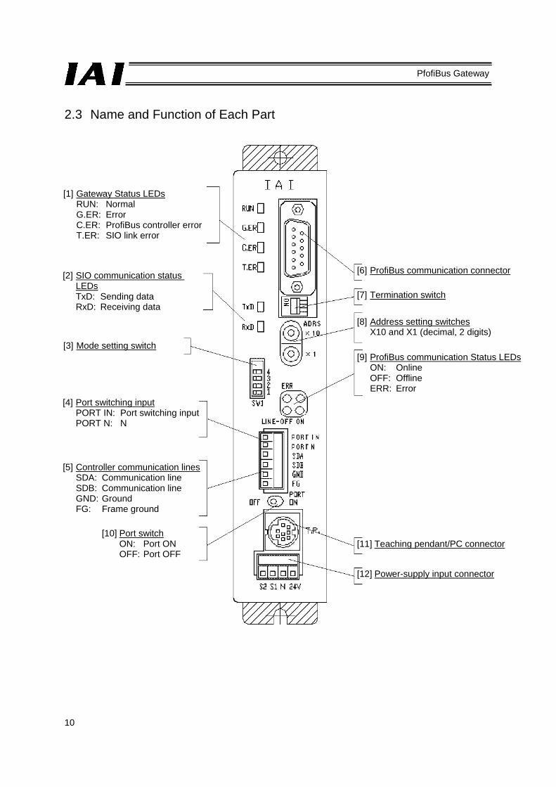
2.3 Name and Function of Each Part
[1] Gateway Status LEDs RUN: Normal G.ER: Error C.ER: ProfiBus controller error T.ER: SIO link error
[2] SIO communication status LEDs TxD: Sending data RxD: Receiving data
[3] Mode setting switch
[4] Port switching input PORT IN: Port switching input PORT N: N
[5] Controller communication lines SDA: Communication line SDB: Communication line GND: Ground FG: Frame ground
[10] Port switch ON: Port ON OFF: Port OFF
[6] ProfiBus communication connector
[7] Termination switch
[8] Address setting switches X10 and X1 (decimal, 2 digits)
[9] ProfiBus communication Status LEDsON: Online OFF: Offline ERR: Error
[11] Teaching pendant/PC connector
[12] Power-supply input connector

11
PfofiBus Gateway
[1] Gateway status LEDs
Indicated status Description RUN Steady green The Gateway CPU is operating.
Unlit CPU operation is stopped. If this LED does not come on after turning on the power, the Gateway is experiencing a CPU error.
G.ER Steady red The Gateway is experiencing a CPU error or major shutdown failure. Unlit Normal state.
C.ER Steady red The ProfiBus module is experiencing an error or the Gateway CPU cannot recognize the ProfiBus connection. (Check the ProfiBus communication status in [9].) Even if this LED is lit, the teaching pendant or PC software can still be connected as long as the RUN LED is lit.
Blinking red While the port is ON, this LED blinks at 1-second intervals. Unlit Normal state.
T.ER Steady red All axes generated a communication error based on SIO communication between the ProfiBus gateway and controller.
Blinking red At least one axis generated a communication error based on SIO communication between the ProfiBus gateway and controller. (No response, overrun, flaming error or CRC(*) error)
Unlit Normal state. * CRC: Cyclic Redundancy Check
A data error detection method commonly used in synchronous transmission. [2] SIO communication status LEDs
These LEDs are used to check the communication status between the ProfiBus Gateway and the controller. Each LED blinks when the host PLC and controller are not communicating via the ProfiBus Gateway, or when the controller is communicating with the teaching pendant or PC software connected via the ProfiBus Gateway.
Indicated status Description
TxD Blinking green Sending data (ProfiBus Gateway → Controller) Unlit Not sending data (ProfiBus Gateway → Controller)
RxD Blinking green Receiving data (Controller → ProfiBus Gateway) Unlit Not receiving data (Controller → ProfiBus Gateway)

12
PfofiBus Gateway
[3] Mode setting switch
This switch is used to set the operation mode of the ProfiBus gateway. Before operating this switch, turn off the ProfiBus gateway power. If any position between No. 1 and No. 5 is selected, the position table settings of the controller will become invalid.
SW1 turns ON when tilted to the right.
: ON X: OFF
No. SW1 I/O bytes
4 3 2 1 Description Output Input
1 X X X X Direct numerical specification mode/Up to 4 axes can be connected 52 28
2 X X X Direct numerical specification mode/Up to 6 axes can be connected 76 40
3 X X X Direct numerical specification mode/Up to 8 axes can be connected 100 52
4 X Direct numerical specification mode/Up to 10 axes can be connected 124 64
5 X X Direct numerical specification mode/Up to 16 axes can be connected 196 100
6 X X X Position-number specification mode, maximum 16 axes 48 48
7 X X X Command specification mode Large 160 160 8 X X Command specification mode Middle 128 128 9 X X Command specification mode Small 64 64
[4] External port switching input
The ON/OFF status of the teaching pendant/PC connector port can be switched using external signals (no-voltage contact type). The connector port is enabled when the port switch [10] on the ProfiBus Gateway is OFF. When the input signal is ON, the port is also ON. (Refer to [10], “Port switch.”) PORT IN: Port control input PORT N: Port control input, N side Use an input current of 7 mA and external signals of no-voltage contact type
[5] Controller communication lines
This terminal is used to connect the communication lines to the SIO communication connector.

13
PfofiBus Gateway
[6] ProfiBus communication connector
This connector is used to connect the ProfiBus communication lines. D-sub, 9-pin connector (female)
ProfiBus communication connector Pin No. Signal name Description
1 NC Not connected 2 NC Not connected 3 B-Line Communication line B (RS485) 4 RTS Request to send 5 GND Signal ground (insulated) 6 +5V +5-V output (insulated) 7 NC Not connected 8 A-Line Communication line A (RS485) 9 NC Not connected
Housing Shield Cable shield Connected to the frame.
The mating connector (cable end) is not supplied. [7] Termination switch
A terminal resistor must be provided at the end of the ProfiBus trunk line to prevent bus reflection. Set the termination switch to the ON position when the ProfiBus Gateway is the terminal module. However, the switch should be set to the OFF position if an external termination connector is used. Set the switch to the OFF position if the Gateway is not the terminal module.
[8] Address setting switches
The two rotary switches are used to set a decimal node address in a range of 1 to 99. X10: Set the 10’s digit of the two-digit decimal address. X1: Set the 1’s digit of the two-digit decimal address. This switch is normally set to 2 for the master unit, and 3 or greater for the slave.

14
PfofiBus Gateway
[9] ProfiBus status LEDs
The three LEDs of (LINE-) ON, LINE-OFF and ERR on the front face of the board indicate the node status and network status. (The remaining LED is not used.) These LEDs illuminate in one of two colors (red or green), and each LED indicates a different monitored status, as shown in the table below.
LED name Color Indicated status Description (meaning of indication)
(LINE-) ON
Green
Lit Online
Unlit Not online
LINE-OFF
Red
Lit Offline
Unlit Not offline
ERR
Red
Blinking at 1-Hz frequency
Configuration error Example: The I/O size determined by
the mode setting switch [3] does not match the I/O size set by the configuration tool.
Blinking at 4-Hz frequency Communication ASIC initialization error
Unlit No error
15
PfofiBus Gateway
[10] Port switch
This switch is used to enable the teaching pendant/PC connector (TP) (PORT ON = Start communication). Set this switch to the OFF position when connecting/removing the communication cable connector for teaching pendant or PC software. To use the teaching pendant or PC software, plug in the connector first, and then set the switch to the OFF position. (Also check the signal status of the port switching input [4].) Port switch ON: Power (24 VDC) is supplied to the teaching pendant. The emergency stop circuit
of the teaching pendant is enabled. Port switch OFF: Power (24 VDC) to the teaching pendant is cut off. The emergency stop circuit of
the teaching pendant is disabled. The baud rate between the teaching pendant or PC software and ProfiBus gateway can be set to a maximum of 115.2 kbps. For your information, the baud rate between the ProfiBus gateway and controller is fixed to 230.4 kbps. When the port switch is turned ON, no ProfiBus communication error will generate, but the data exchange via SIO communication will stop. Accordingly, the PLC’s output signals (data) will no longer be output to the controller and the input signals (data) from the controller will remain as the values that were effective immediately before the port switch was turned ON. A PORT ON status signal (TPC) is output from the ProfiBus gateway to the PLC, so provide an interlock or other process as necessary.
[11] Teaching pendant/PC connector
This connector is used to connect the communication cable connector for teaching pendant or PC software.
[12] Power-supply input connector
This connector is used to connect the ProfiBus Gateway power (24 VDC).

16
PfofiBus Gateway
3. Installation and Noise Elimination Measures
Exercise due caution regarding the installation environment. 3.1 Installation Environment.
a. The Gateway Unit is not dustproof or waterproof (oilproof). Accordingly, avoid using the Gateway Unit in a dusty place or place where the unit may come in contact with oil mist or splashed cutting fluid.
b. Prevent the Gateway Unit from receiving direct sunlight or irradiated heat from large heat sources such as heat treatment ovens.
c. Use the Gateway Unit in an environment of 0 to 40°C in ambient temperature and 85% or below in humidity (non-condensing) and free from corrosive or flammable gases.
d. Use the Gateway Unit in an environment where the unit will not receive external vibration or shock.
e. Prevent electrical noise from entering the Gateway Unit or its cables. 3.2 Supply Voltage
24 VDC ± 10% / Current consumption: 300 mA max. 3.3 Noise Elimination Measures and Grounding
a. Installing the Gateway Unit
Connect the Gateway Unit by directly securing it onto a metal enclosure using screws.
Use as thick a cable as possible and connect it over the shortest possible distance.
Metal enclosure
* Provide class D (3) grounding for the enclosure.

17
PfofiBus Gateway
b. Notes on wiring method
Separate the communication lines of the Gateway Unit and ProfiBus module from lines carrying large current such as power circuits. (Do not bundle them together or place them in the same cable duct.)
c. Noise sources and elimination of noise
There are many noise sources, but the ones you should pay most attention to when building your system are solenoid valves, magnet switches and relays. Noise from these sources can be eliminated using the following measures.
[1] AC solenoid valves, magnet switches, relays
Measure --- Install a surge killer in parallel with the coil.
[2] DC solenoid valves, magnet switches, relays
Measure --- Install a diode in parallel with the coil. Determine an appropriate diode capacity in accordance with the load capacity.
← Point Install the surge killer in a location as close as possible to each coil. If the surge killer is installed on a terminal block or away from the coil, its noise elimination effect will decrease.
In a DC system, connecting the diode in reverse polarities may damage the diode, internal controller parts, and DC power supply. Exercise due caution.
+24 V 0 V

18
PfofiBus Gateway
3.4 Installation Examine appropriate settings for the control box size, installation position of the Gateway Unit and cooling method of the control box, so that the temperature around the Gateway Unit will remain at or below 40°C. Install the Gateway Unit vertically on a wall, as shown below, and provide a minimum clearance of 50 mm above and below the unit, with a minimum clearance of 100 mm provided on all sides for wiring access. If multiple Gateway Units are installed side by side, provide a sufficient space between the adjacent units so that any unit can be installed and removed easily. If heat or noise is of concern, also provide appropriate measures.

19
PfofiBus Gateway
4. Wiring 4.1 Overall Configuration The following is an example of ProfiBus system configuration using the Gateway Unit.
SIO
com
mun
icat
ion
netw
ork
Term
inal
resi
stor
4-w
ay ju
nctio
n
Hos
t sys
tem
(PLC
mas
ter)
Gat
eway
U
nit
Teac
hing
pen
dant
24-V
po
wer
su
pply
Con
trolle
r lin
k ca
ble

20
PfofiBus Gateway
The ProfiBus network is wired as shown below.
For details on ProfiBus-DP, check the operation manual for the master (PLC) or website of the Japanese PROFIBUS Organization.
[1] A device connected to a network and assigned an address is called a “node.” A node may be a
master or slave. Up to 32 nodes can be connected to one segment. [2] It is recommended that the master be connected to one end of the network. Normally the master has
node address 2, while each slave has node address 3 to 32. Node address 0 is reserved for a monitoring or diagnostic device, while node address 1 is reserved for a monitoring device.
[3] One segment of the network must have a terminal resistor connected to both ends. [4] For each ProfiBus cable, use the ProfiBus-DP type A cable specified by the EN 50170 standard. This
cable is a 2-core twisted pair cable with shield. [5] All network connectors should be the D-sub, 9-pin connector specified by the EN 50170 standard.
The network bus connector can be of the screw type shown below or the quick connection type where the wires are inserted into provided holes.
If the connector has a terminal resistor, turn the terminal resistor switch ON only for the terminal slave, and turn the switch OFF for all other slaves.
Master (Node address 2)
Slave Slave Slave Slave
Terminal resistor
Terminal resistor
(Node address 3) (Node address 4) (Node address 5) (Node address 6)
CableRed: Line B (positive side)
Green: Line A (negative side)
Shield

21
PfofiBus Gateway
[6] The ProfiBus gateway connector should be the D-sub, 9-pin (female) connector recommended by the
ProfiBus DP Standard under EN 50170, as shown below. The network connectors are not supplied.
Pin No. Signal name Description
1 NC Not connected 2 NC Not connected 3 B-Line Communication line B (Positive side) 4 NC Not connected 5 GND Signal ground 6 +5V +5-V output 7 NC Not connected 8 A-Line Communication line A (Negative side) 9 NC Not connected
Housing Shield Cable shield
Caution The ProfiBus gateway has a built-in terminal resistor setting switch. If the ProfiBus gateway becomes a terminal module on the network, turn this terminal resistor setting switch ON. If the ProfiBus gateway is not a terminal module or an external terminal connector is used, turn the switch OFF.

22
PfofiBus Gateway
4.2 I/O Signals of Gateway Unit (1) Connection diagram
Gateway Unit
ProfiBus communication cable
Teaching pendant Teaching pendant/ PC connector
Emergency stop
Emergency stop signal output for teaching pendant Allowable load voltage: 30 VDC Allowable load current: 1 A
Gateway power supply 24 VDC ±10%, 300 mA max.
External port switching input (provided by the customer)
(Load: 24 VDC, 7 mA)
Port switch
SIO communication cable

23
PfofiBus Gateway
(2) Port control and emergency stop signal output
The teaching pendant/PC connector port can be operated by external signals, other than by ON/OFF switching of the port switch on the Gateway Unit. While the port is ON, the Gateway Unit outputs contact signals of the emergency stop pushbutton switch on the teaching pendant. Therefore, you can design an emergency stop circuit or other protective circuit for the entire system by incorporating these signals.
External port
switching input Port switch Teaching-pendant emergency stop signal output
Teaching pendant/PC connector port
OFF OFF Disabled (S1 and S2 shorted) Disabled ON OFF
Enabled S1, S2 = Teaching-pendant emergency stop contacts
Enabled OFF ON ON ON
An example of the emergency stop circuit is shown below.
Emergency stop reset
Emergency stop button switches
ProfiBus cable
Teaching pendant
Emergency stop
Gateway unit
Teaching pendant/PC connector
Gateway power supply (24 VDC ± 10%, 300 mA max.)
External port switching input (provided by the customer)
(Load 24 VDC, 7 mA)
SIO communication cable
Port switch

PRO
FIBUS G
ateway
24
Symbol Description Specification Connector and applicable wire
Pow
er-s
uppl
y in
put c
onne
ctor
24 V Positive side of the 24-VDC
Gateway power supply 24 VDC ±10% 0.8 to 1.3 mm2 The connection plug is a standard accessory. MC1.5/4-ST-3 5 (Phoenix Contact)
N Negative side of the 24-VDC Gateway power supply
Power consumption: 300 mA max. AWG 18 to 16
S1 Teaching-pendant emergency stop signal output
Allowable load voltage: 30 VDC 0.08 to 1.5 mm2 S2 Allowable load current: 1 A AWG 28 to 16
SIO
com
mun
icat
ion
conn
ecto
r
PORT IN External port switching input No-voltage (dry) contact input Load: 24 VDC, 7 mA
0.08 to 1.5 mm2 AWG 28 to 16
The connection plug is a standard accessory. MC1.5/6-ST-3 81 (Phoenix Contact) The Gateway Unit has a built-in terminal resistor, so connect the terminal resistor at the end of the SIO communication line.
PORT N SDA SIO communication line A Align the potential level of the
connected controller or ERC actuator with the potential level of the GND (ground).
Double shielded twisted-pair cable (AWG22) Recommended cable: HK-SB/20276 X L 2P X AWG22 by Taiyo Electric Wire & Cable
SDB SIO communication line B
GND Ground
FG Frame ground Internally connected to the frame.
Pro
fiBus
co
mm
unic
atio
n co
nnec
tor
B-Line Communication line B (RS485) ProfiBus-DP type A cable
(2-core twisted pair cable with shield)
The connection plug should be a D-sub, 9-pin connector, but this plug is not supplied. With ProfiBus, a terminal resistor*1 must be connected to both ends of the trunk line. For details, check the operation manual for the master (PLC).
RTS Request to send GND Signal ground (insulated) +5V +5-V output (insulated)
A-Line Communication line A (RS485)
*1 The gateway unit has a built-in terminal resistor. Set the terminal switch ON/OFF to enable/disable this built-in terminal resistor.
(3) I/O
signal specifications and wires

25
PfofiBus Gateway
4.3 Design of SIO Communication Network (SIO Communication) 4.3.1 Wiring (1) Basics
Item Description
Number of connected units 16 axes max. (The specific number varies depending on the operation mode. Refer to 1.4, “Features of Gateway Unit.”)
Communication cable length Total cable length: 100 m max.
Communication cable Double shielded twisted-pair cable (AWG22) Recommended cable: HK-SB/20276 X L 2P X AWG22
by Taiyo Electric Wire & Cable Terminal resistor 220 Ω 1/4 W
Caution
1. Connect the communication path to a bus and always connect a terminal resistor at the end. A terminal resistor is not needed on the Gateway Unit end, as the unit has a built-in terminal resistor.
2. The customer must provide the communication cable. If the recommended cable is not used, make sure the size of the cable to be used is AWG22.
(2) Communication connection for PCON, ACON and SCON *1 A terminal resistor (220 Ω, 1/4 W) is supplied with the controller link cable.
Gateway Unit (Built-in terminal resistor)
SIO communication trunk line (provided by the customer)
e-CON connector (4-1473562-4 by AMP, green) e-CON connector (3-1473562-4 by AMP, orange)
Junction (5-1473574-4 by AMP)
Recommended cable: SB/20276 X L 2P X AWG22
Axis 1 Axis 2 Axis n
Controller link cable
Terminal resistor *1

26
PfofiBus Gateway
a. Detail connection diagram
Details of SIO link connection are illustrated below. Controller link cables are available as options, but the customer must provide the communication trunk.
b. Producing a communication trunk
[1] Strip the sheath of a double shielded twisted-pair cable by approx. 15 to 20 mm.
[2] Twist the shield wires and solder them onto the vinyl wires of AWG22 or equivalent.
[3] Place a cable protection tube over the cable. [4] Insert the core wires, without stripping them, into the
cable insertion holes in the connector (SDA, SDB, GND, FG).
[5] With the cable inserted in the press-fit cable housing, apply pressure from above to pressure-weld the core wires.
[6] Heat-treat the cable protection tube. e-CON connector pin numbers
Always insert a terminal resistor (220 Ω, 1/4 W) at the end of the communication trunk (between pins 1 and 2 of the e-CON connector).
Gateway Unit Double shielded twisted-pair cable Recommended cable: HK-SB/20276 X L 2P X AWG22 by Taiyo Electric Wire & Cable
SIO communication trunk
4-way junction (5-1473574-4 by AMP)
e-CON connector (4-1473562-4 by AMP)Housing color: Green
Controller link cable
Yellow
Orange
Blue
Yellow
Orange
Blue
e-CON connector (3-1473562-4 by AMP)Housing color: Orange
Unit 1 Unit 2
Locking tab
e-CON connector
Apply pressure.
Cable tube
Double shielded twisted-pair shielded
Locking tab
Vinyl wire (AWG22)
Solder
Shield wire

27
PfofiBus Gateway
c. Controller link cable (CB-RCB-CTL002)
This is an optional cable for the controller. You must purchase this cable separately.
The following parts are supplied with the controller link cable. [1] 4-way junction Model: 5-1473574-4 by AMP x 1 unit [2] e-CON connector 4-1473562-4 by AMP x 1 unit Outer diameter of applicable wire 1.35 to 1.6 mm [3] Terminal resistor 220 Ω 1/4 W With e-CON connector x 1 unit
Controller end
Mini DIN connector
e-CON connector 3-1473562-4 (Housing color: Orange)
Signal YellowOrange
Blue
Signal

28
PfofiBus Gateway
(3) SIO communication connection for ERC2-SE
For details, refer to the ERC2-SE operation manual. Use 4-way junctions to connect the cables as shown below. The power-supply & I/O cable and network connection cable (including the 4-way junction and e-CON connector) are standard accessories of the ERC2-SE.
Caution
(1) When the total communication cable length is 10 m or longer, communication may not be established properly and a communication error may occur. In this case, connect a terminal resistor to the last axis.
(2) If the actuators have different power supplies, use a common line for 0 [V]. (3) Use a common line for 0 [V] for the power supply of the gateway unit and control power supply of
the ERC2. (4) Connect the shield wire to the FG for each axis. (5) If the total link cable length exceeds 30 m, use wires with a size of 22AWG or larger.
PIO & 24-VDC control power, motor power, brake signal, ground, shield
Gateway unit
4-way junction
e-CON connector
Network connection cable (CB-ERC2-CTL001)
Power-supply & I/O cable (CB-ERC2-PWBIO)
JST JST Axis 1
Axis 2
Axis 3 Fabricated by the customer
Terminal resistor
Axis 16

29
PfofiBus Gateway
(4) SIO communication connection for ERC2-NP/PN
Use relay terminal blocks to connect the cables as shown below.
Caution (1) When the total communication cable length is 10 m or longer, communication may not be
established properly and a communication error may occur. In this case, connect a terminal resistor to the last axis.
(2) If the actuators have different power supplies, use a common line for 0 [V]. (3) Use a common line for 0 [V] for the power supply of the gateway unit and control power supply of
the ERC2. (4) Connect the shield wire to the FG for each axis. (5) If the total link cable length exceeds 30 m, use wires with a size of 22AWG or larger.
PIO & 24-VDC control power, motor power, brake signal, ground, shield
Terminal resistor
Gateway unit
Axis 1
Axis 2
Axis 16
Relay terminal block Orange
(red 1)
PIO type power-supply & I/O cable
Orange (black 1)
Pair shield cable (fabricated by the
customer)

30
PfofiBus Gateway
(5) Wiring the emergency stop (EMG) circuit When designing an emergency stop circuit that incorporates the emergency stop switch on the teaching pendant connected to the Gateway Unit, emergency stop signals output from the “S1” and “S2” terminals of the Gateway Unit can be used. This way, all connected ROBO Cylinder controllers can be stopped instantly in case of emergency by operating the emergency stop switch on the teaching pendant connected to the Gateway Unit.
Caution
1. For details on the emergency stop processing of ROBO Cylinders, refer to the operation manual for your PCON, ACON, SCON or ERC-2 controller.

31
PfofiBus Gateway
[1] Example of cutting off drive signals
Caution
The input current specification for the EMG terminal is 5 mA. When connecting the EMG relay CR contacts to the EMG terminals of multiple controllers, check the current capacity of the relay contacts.
Teaching pendant Gateway Unit Emergency stop button
TP connector
Gatewaypower supply
Port switch
SIO communication
SIO connector PCON, ACON controller
24-VDC input power supply
(2 A max. per unit)
Power-supply terminal block
Connection detection signal (H)
SIO connector connection detection
circuit
EMG signal detection (H)
Motor drive power
Control power
Time cons-tant
Drive stop signal (L)
Motor drive circuit
Power-supply terminal block (unit 2)
Power-supply terminal block (unit 3)
Emergency stop reset switch Emergency
stop button

32
PfofiBus Gateway
[2] Example of cutting off motor drive power
Teaching pendant Gateway Unit
TP connector
Gatewaypower supply
Port switch
SIO communication
SIO connector PCON, ACON controller
24-VDC input power supply
(2 A max. per unit)
Power-supply terminal block
Connection detection signal (H)
SIO connector connection detection
circuit
EMG signal detection (H)
Motor drive power
Control power
Time cons-tant
Drive stop signal (L)
Motor drive circuit
Power-supply terminal block (unit 2)
Power-supply terminal block (unit 3)
Emergency stop button
Emergency stop reset switch Emergency
stop button

33
PfofiBus Gateway
4.3.2 Axis Number Setting The following explanation applies to PCON, ACON and ERC2 controllers.
Set an axis number as a SIO-linked slave station number. The axis number of axis 1 is “0,” while that of axis 16 is “F.” Set an appropriate axis number using a hexadecimal value between 0 and F. Axis numbers can be set on the teaching pendant or in the PC software.
Operation in the PC software
[1] Open the main window → [2] Click Settings (S) → [3] Bring the cursor to Controller Settings (C) → [4] Click Assign Axis Number (N) → [5] Enter a number in the axis number table.
Operation on the teaching pendant RCM-T
[1] Open the User Adjustment window → [2] Bring the cursor to Assigned No. using the key → [3] Enter an axis number, and press Enter → [4] Enter “2” under Adjustment No., and press Enter.
Operation on the simple teaching pendant RCM-E
[1] Open the User Adjustment window [2] Press Enter to open the Assigned No. window → [3] Enter an axis number, and press Enter → [4] Enter “2” under Adjustment No., and press Enter.
For details on each setting method, refer to the operation manual for your teaching pendant or PC software.
Caution
1. Each axis number must be unique. 2. Before setting an axis number for a given axis, disconnect the link cable of the applicable axis. 3. Connect a terminal resistor between SGA and SGB on the terminal module.

34
PfofiBus Gateway
4.4 How to Connect the Teaching Tool When the Positive Terminal of the
24-V Power Supply Is Grounded If the positive terminal of the 24-V power supply is grounded (= +24 V is grounded), use a SIO converter as shown below to connect a teaching pendant or PC to the gateway unit. In this case, do not connect the FG of the SIO converter. With the gateway unit system, the negative terminal of the 24-V power supply should be grounded (= 0 V should be grounded), as a rule. Since most teaching pendants and PCs have their communication ground line and FG (frame ground) shorted internally, grounding the positive terminal of the 24-V power supply (= grounding +24 V) will cause shorting of the 24-V power-supply circuit when a teaching pendant or PC is connected to the gateway unit, thereby damaging the teaching pendant or PC.
Caution
Do not connect the FG of the SIO converter.
Teaching pendant PC, etc.
Do not allow the FG of the PC to be connected to ground. If the FG may be connected to ground via other COM port, disconnect the communication cable from the applicable COM port.
PC software
RS232 connection type <Model number: RCM-101-MW> USB connection type <Model number: RCM-101-USB> * The cables are supplied with the
PC software.
SIO converter (optional) (with built-in terminal resistor) Model number: RCB-TU-SIO-A (B) Gateway unit
Do not connect the FG.
* One e-CON connector, one junction and one terminal resistor are supplied with each controller link cable.
e-CON connector (3-1473562-4 by AMP) Junction (5-1473574-4 by AMP)
Terminal resistor
Controller link cable Model number: CB-RCB-CTL002
24-V power supply

35
PfofiBus Gateway
5. Address Configuration of Gateway Unit All data exchanged between the master station and the controller are tentatively stored in the internal memory of the Gateway Unit, and then transmitted cyclically. Accordingly, the PLC program recognizes these data as remote ProfiBus I/Os. Up to 16 ROBO Cylinder controllers can be connected to the Gateway Unit, with the connected controllers assigned an axis number of 0 to 15, respectively. The Gateway Unit simultaneously sends and receives data to/from the master station for all ROBO Cylinder controllers connected via SIO link. As explained in the features of the Gateway unit in section 1.4, controllers can be operated in there major modes. In each mode, an address configuration varies as the slave. 5.1 Position Number Specification Mode In this operation mode, a desired position number in the position table is specified to operate the actuator, and up to 16 axes can be controlled. The position table must be set for each axis using the PC software or teaching pendant. A desired position number is written in the PLC to operate the actuator. Up to 64 positions from Nos. 0 to 63 can be specified, but the number of positions may be limited depending on the PIO pattern (PIO pattern selection parameter) specified for each axis. (Refer to the table in 1.4.2.) The key functions that can be controlled in this mode are summarized in the table below.
Key function : Direct control
∆: Indirect control X: Disabled
Remarks
Home return operation Positioning operation ∆ This operation is performed by
specifying a number in the position table.
Speed and acceleration/deceleration setting
∆ Set in the position table.
Pitch (incremental) feed ∆ Set in the position table. Push-motion operation ∆ Set in the position table. Speed change during movement ∆ This operation is performed by
combining two or more position numbers. (Refer to the operation manual for the controller.)
Operation with acceleration and deceleration set differently
∆ Set in the position table.
Pause Zone signal output Each zone is set by parameters. PIO pattern selection X *1 *1 Since the number of position is limited according to the PIO pattern selection (parameter No. 25)
specified for each connected controller, specify the position numbers in a manner avoiding inconsistency. For your information, up to 64 positions can be specified.

36
PfofiBus Gateway
5.1.1 Overall address configuration
In the position number specification mode, four bytes are used by the gateway control signals, and also by the status signals, to be input/output. For each axis, each control signal occupies two bytes in the PLC I/O area, and a total of 48 bytes are occupied by signal inputs, and also by signal outputs, for the entire gateway unit. The values in parentheses ( ) indicate axis numbers.
* The byte address is indicated as a relative byte address from the initial byte-address byte of the
gateway.
Output from PLC ⇒ Gateway Unit ⇒ Input to each axis Output from each axis ⇒ Gateway Unit ⇒ Input to PLC * Byte address Upper byte Lower byte
Gateway control signal 0
Gateway control signal 1
Control signal (0)
Control signal (1)
Control signal (2)
Control signal (3)
Control signal (4)
Control signal (5)
Control signal (6)
Control signal (7)
Control signal (8)
Control signal (9)
Control signal (10)
Control signal (11)
Control signal (12)
Control signal (13)
Control signal (14)
Control signal (15)
Cannot be used.
Cannot be used.
Cannot be used.
Cannot be used.
Cannot be used.
Cannot be used.
Gateway status signal 0
Gateway status signal 1
Status signal (0)
Status signal (1)
Status signal (2)
Status signal (3)
Status signal (4)
Status signal (5)
Status signal (6)
Status signal (7)
Status signal (8)
Status signal (9)
Status signal (10)
Status signal (11)
Status signal (12)
Status signal (13)
Status signal (14)
Status signal (15)
Cannot be used.
Cannot be used.
Cannot be used.
Cannot be used.
Cannot be used.
Cannot be used.
Cannot be used.
Cannot be used.
Cannot be used.
Cannot be used.
Cannot be used.
Cannot be used.
Completed position number (0)
Completed position number (1)
Completed position number (2)
Completed position number (3)
Completed position number (4)
Completed position number (5)
Completed position number (6)
Completed position number (7)
Completed position number (8)
Completed position number (9)
Completed position number (10)
Completed position number (11)
Completed position number (12)
Completed position number (13)
Completed position number (14)
Completed position number (15)
1 byte
Cannot be used.
Cannot be used.
Cannot be used.
Cannot be used.
Cannot be used.
Cannot be used.
Command position number (0)
Command position number (1)
Command position number (2)
Command position number (3)
Command position number (4)
Command position number (5)
Command position number (6)
Command position number (7)
Command position number (8)
Command position number (9)
Command position number (10)
Command position number (11)
Command position number (12)
Command position number (13)
Command position number (14)
Command position number (15)
1 byte 1 byte 1 byte
Upper byte Lower byte

37
PfofiBus Gateway
5.1.2 Gateway Control/Status Signals The initial fixed area in the address configuration is used by signals that control the gateway unit, and consists of four input bytes and four output bytes. These signals are used to control the ON/OFF of SIO communication and monitor the SIO communication status and gateway unit status. PLC output PLC input
* The byte address is indicated as a relative byte address from the initial byte-address byte of the gateway.
Gateway control signal 0
Gateway control signal 1
Byte address
Gateway status signal 0
Gateway status signal 1

38
PfofiBus Gateway
I/O Signal List
Signal type Byte Bit Signal name Description
PLC
out
put
Control signal 0
+0 7 MON
SIO link communication will start when this signal is turned ON, and stop when it is turned OFF. Do not turn the MON signal ON when CFG15 to 0 (linked axis connection) are all OFF. Also, do not turn all of CFG15 to 0 OFF when the MON signal is ON. If CFG15 to 0 are all turned OFF and the MON signal turned ON, the Gateway Unit will generate a SIO link error and the LED (T.ER) on the front face of the unit will illuminate.
6-0 - These bits cannot be used. Always set them to OFF (0).
+1
7 NPS4 These bits are used in the command specification mode. In all other modes, always set these bits to OFF (”0”). Set the axis number (0 to 16) corresponding to each axis operated by positioner operation, using a 5-bit binary code. *1
6 NPS3 5 NPS2 4 NPS1 3 NPS0 2 PPS2 These bits are used in the command specification mode.
In all other modes, always set these bits to OFF (”0”). Set the I/O pattern (pattern 0 to 4) of the axis using a 3-bit binary code. *2
1 PPS1 0 PPS0
Control signal 1
+2
7 CFG15 Link ON Axis No. 15 Specify the axis number corresponding to each axis to be linked. The axis will be connected when the signal is turned ON (1), and disconnected when it is turned OFF (0).ON/OFF switching is permitted even when the MON signal is ON. (Cautions)
Do not turn ON the axis number signal corresponding to any axis not physically connected.
Do not turn ON any axis number signal other than the specifiable number selected by the mode setting switch.
If either of the above conditions is breached, a SIO link error will occur.
6 CFG14 145 CFG13 134 CFG12 123 CFG11 112 CFG10 101 CFG9 90 CFG8 8
+3
7 CFG7 76 CFG6 65 CFG5 54 CFG4 43 CFG3 32 CFG2 21 CFG1 10 CFG0 0
*1 If the mode setting switch (SW1) specifies the command specification mode and NPS0 to NPS4 are
set to 0, all axes will become simple direct operation axes. *2 For positioner operation axes, only one I/O pattern of 0 to 4 can be specified.

39
PfofiBus Gateway
Signal type Byte Bit Signal name Description
PLC
inpu
t
Status signal 0
+0
7 RUN Gateway Unit normal output
This signal remains ON while the Gateway Unit is operating normally. The signal is synchronized with the illumination of the LED (RUN) on the front face of the unit.
6 G.ER Gateway Unit error detection output
This signal turns ON when a major shutdown failure has been detected. The signal is synchronized with the illumination of the LED (G.ER) on the front face of the unit.
5 T.ER SIO-link communication error detection output
This signal turns ON when a SIO link communication error has been detected. The signal is synchronized with the illumination of the LED (T.ER) on the front face of the unit.
4 TPC Port switch ON output The status of the port switch on the front face of the unit is output. This signal is ON while the port switch is ON.
3 MOD4 Mode setting switch 4 ON output
The setting status of each pin of the mode setting switch is output. When the switch is turned ON, the applicable bit will turn ON (“1”).
2 MOD3 Mode setting switch 3 ON output
1 MOD2 Mode setting switch 2 ON output
0 MOD1 Mode setting switch 1 ON output
+1
7 Major V.4 The major version number is output as a three-bit binary value.
The Gateway version information is output.You may need to check this information in certain situations, such as when the Gateway encountered a problem. Provide the necessary wiring so that these signals can be read by the PLC. Example) If the version is 1.03, the major
version number is “1” (data: 001), while the minor version number is “3” (data: 00011).
6 Major V.2 5 Major V.1 4 Minor V.16
The major version number is output as a five-bit binary value.
3 Minor V.8 2 Minor V.4 1 Minor V.2 0 Minor V.1
Status signal 1
+2
7 LNK15 Linked Axis No. 15
Link connection of an axis selected for link connection by any one of CFG15 to 0 will become enabled when the MON signal is turned ON. The signal corresponding to each axis whose link connection is enabled turns ON.
6 LNK14 145 LNK13 134 LNK12 123 LNK11 112 LNK10 101 LNK9 90 LNK8 8
+3
7 LNK7 76 LNK6 65 LNK5 54 LNK4 43 LNK3 32 LNK2 21 LNK1 10 LNK0 0

40
PfofiBus Gateway
5.1.3 Assignment for Each Axis
The input signal and output signal of each axis consist of two bytes each in the PLC I/O area. Control signals and status signals are ON/OFF signals defined in units of bits. The command position number or completed position number is handled as a 1-byte (8-bit) binary data. Specify each command position number within the range of position numbers set by the controller of each axis.
PLC output PLC input
* Byte: Initial gateway address n: Axis number (0 to 15)
Byte address*
Byte address
Control signal
Command position number
Status signal
Completed position number

41
PfofiBus Gateway
I/O Signal Details
Signal type Bit Signal name Description Details
PLC
out
put Control
signal
b7 - Cannot be used. - b6 - Cannot be used. - b5 - Cannot be used. - b4 SON Servo on command 6.2 (7) b3 STP Pause command 6.2 (5) b2 HOME Home return command 6.2 (8) b1 CSTR Start command 6.2 (9) b0 RES Reset command 6.2 (4)
Command position number
6-bit data
(b5-0)
RC 32 ~
PC1
Specify the command position number using a binary value.*1
6.2 (11)
PLC
inpu
t
Status signal
b7 EMGS Emergency stop 6.2 (2) b6 - Cannot be used. - b5 PWR Controller ready 6.2 (1) b4 SV Ready (servo is on) 6.2 (7) b3 MOVE Moving 6.2 (6) b2 HEND Home return complete 6.2 (8) b1 PEND Positioning complete 6.2 (10) b0 ALM Alarm 6.2 (3)
Zone signal output 2 b7 ZONE2
*2 The completed position number and zone signal status are output. Read the completed position number as a six-bit binary value. While an alarm is present (= the ALM signal is ON), the content of the alarm is output to the completed position number. (For the contents of alarms that may be output, refer to the table entitled “Alarm List” on the next page.)
6.2 (13) Zone signal
output 1 b6 ZONE1
Completed position number (alarm output)
6-bit data
(b5-0)
PM32 ~
PM1 6.2 (12)
*1 With the ERC2-NP/PN, up to 16 positioning points are supported in PIO control. If the gateway unit is
connected, however, up to 64 points can be specified. *2 [ZONE2] is not supported by the ERC2-NP/PN.

42
PfofiBus Gateway
[Alarm List] The table below summarizes the content of each alarm that may be output by PM8 to PM1 (as a binary code) while the alarm is present. For details on each alarm, refer to the operation manual for the controller.
: ON X: OFF
ALM PM8 PM4 PM2 PM1 Output code Description *2 Remarks
X - - - - - Normal X X X 1 For manufacturer’s use *1 X X X 2 For manufacturer’s use *1
X X 3
Movement command issued with servo off (80) Position command issued before completion of home return (82) Absolute position movement command issued before completion of home return (83) Movement command issued during home return (84)
X X X 4 PCB inconsistency error (F4) X X 5 Non-volatile memory write error (F7) *1
X X 6 Parameter data error (A1) Position data error (A2) Position command information data error (A3)
X 7 Excitation detection error (B8) Operation timeout during home return operation (BE)
X X X 8 Excessive actual speed (C0)
X X 9
Overvoltage (C9) Overheat (CA) Control power-supply voltage error (CC) Control power-supply voltage low (CE)
X X A For manufacturer’s use *1 X B Position deviation counter overflow (D8) X X C Servo error (C1)
X D
Open phase A, B (E8) Open phase A (E9) Open phase B (EA) RCP2 absolute encoder error detection 1 (ED) RCP2 absolute encoder error detection 2 (ED) RCP2 absolute encoder error detection 3 (ED)
X E CPU error (FA) FPGA error (FB)
F Non-volatile memory write count over (F5) Non-volatile memory writing timeout (F6) Non-volatile memory data corrupted (F8)
*1 This error will not generate when the gateway unit is used. *2 The corresponding alarm code displayed on the PC software or teaching pendant is shown in
parentheses ( ).

43
PfofiBus Gateway
5.2 Direct Numerical Specification Mode In the direct numerical specification mode, the position data, speed, acceleration/deceleration, positioning band (push band) and push-current limiting value are specified directly as numerical values to operate the actuator. One of five patters can be set according to the maximum number of connected axes. (Mode setting switch SW1) Also, the current position data can be read at any time. The position table need not be set for each axis. The key functions that can be controlled in this mode are summarized in the table below.
Key function : Direct control
∆: Indirect control X: Disabled
Remarks
Home return operation Positioning operation Speed/acceleration setting Pitch (incremental) feed X Pitch feed data cannot be processed directly.
The host PLC must issue each command by adding/subtracting the pitch-feed distance data to/from the current position.
Push-motion operation Speed change during movement Speed data is accepted at the start of
positioning. To change the speed during movement, therefore, change the speed data during movement and then restart the positioning operation.
Operation with acceleration and deceleration set differently
Acceleration/deceleration data is accepted at the start of positioning. To specify a deceleration different from the acceleration, therefore, change the deceleration data during movement and then restart the positioning operation.
Pause Zone signal output X Monitor the current position using the PLC. *1 PIO pattern selection X *2 *1 The current position data does not use strobe signals. Accordingly, to check the current position
using the PLC while the actuator is moving, set a zone and confirm that the data has remained in the specified zone for at least two scan periods.
*2 Set the PIO pattern selection parameter (No. 25) of the connected controller to 0 (standard type). (PCON-C/CG, ACON-C/CG, SCON-C, ERC-2NP/PN)

44
PfofiBus Gateway
5.2.1 Overall Address Configuration
Four bytes are used by the gateway control signals, and also by the status signals, to be input/output. In the direct numerical specification mode, the control signals of each axis consist of 12 bytes in the PLC output area (gateway input area) and six bytes in the PLC input area (gateway output area). The number of controlled axes is set by the mode setting switch (SW1), and the applicable data areas vary depending on the setting of this switch. The switch settings and corresponding data areas are shown below.
No. SW1 I/O bytes 4 3 2 1 Description Output Input
1 X X X X Direct numerical specification mode/Up to 4 axes can be connected 52 28
2 X X X Direct numerical specification mode/Up to 6 axes can be connected 76 40
3 X X X Direct numerical specification mode/Up to 8 axes can be connected 100 52
4 X Direct numerical specification mode/Up to 10 axes can be connected 124 64
5 X X Direct numerical specification mode/Up to 16 axes can be connected 196 100
: ON X: OFF

45
PfofiBus Gateway
The overall address configuration is shown below. The byte address indicates the initial address of the assigned area in the master. The values in parentheses ( ) indicate axis numbers.
Output from PLC ⇒ Gateway Unit ⇒ Input to each axis
Output from each axis ⇒ Gateway Unit ⇒ Input to PLC
Byte address Byte+ Byte+
Gateway control 0 Gateway control 1
Axis control (0)
Axis control (1)
Axis control (2)
Axis control (3)
Axis control (4)
Axis control (5)
Axis control (6)
Axis control (7)
Axis control (8)
Axis control (9)
Axis control (10)
Axis control (11)
Axis control (12)
Axis control (13)
Axis control (14)
Axis control (15)
Gateway status 0 Gateway status 1
Axis status (0) Axis status (1)
Axis status (2) Axis status (3) Axis status (4) Axis status (5) Axis status (6) Axis status (7) Axis status (8) Axis status (9)
Axis status (10) Axis status (11) Axis status (12) Axis status (13) Axis status (14) Axis status (15)
Mode No. 1
Mode No. 2
Mode No. 3
Mode No. 4
Mode No. 5
Byte data Status signal (11)Status signal (11)Current position data (11)
Cannot be used.
Current position data (11)Current position data (11)
Byte data (11) (11) (11) Current-limiting value for push motion (11) (11) (11) (11) (11) (11) (11) (11) Control signal (11)
Position data specification
Position data specification
Position data specification
Speed specification
Speed specification
Speed specification Acceleration/deceleration specification Positioning band specification Positioning band specification Positioning band specification

46
PfofiBus Gateway
Byte address
Gateway control signal 0
Gateway control signal 1
Gateway status signal 0
Gateway status signal 1
5.2.2 Gateway Control/Status Signals The initial fixed area in the address configuration is used by signals that control the gateway unit, and consists of four input bytes and four output bytes. These signals are used to control the ON/OFF of SIO communication and monitor the SIO communication status and gateway unit status. PLC output PLC input
* The byte address is indicated as a relative byte address from the initial byte-address byte of the gateway.

47
PfofiBus Gateway
I/O Signal List
Signal type Byte Bit Signal name Description
PLC
out
put
Control signal 0
+0 7 MON
SIO link communication will start when this signal is turned ON, and stop when it is turned OFF. Do not turn the MON signal ON when CFG15 to 0 (linked axis connection) are all OFF. Also, do not turn all of CFG15 to 0 OFF when the MON signal is ON. If CFG15 to 0 are all turned OFF and the MON signal turned ON, the Gateway Unit will generate a SIO link error and the LED (T.ER) on the front face of the unit will illuminate.
6-0 - These bits cannot be used. Always set them to OFF (0).
+1
7 NPS4 These bits are used in the command specification mode. In all other modes, always set these bits to OFF (”0”). Set the axis number (0 to 16) corresponding to each axis operated by positioner operation, using a 5-bit binary code. *1
6 NPS3 5 NPS2 4 NPS1 3 NPS0 2 PPS2 These bits are used in the command specification mode.
In all other modes, always set these bits to OFF (”0”). Set the I/O pattern (pattern 0 to 4) of the axis using a 3-bit binary code. *2
1 PPS1 0 PPS0
Control signal 1
+2
7 CFG15 Link ON Axis No. 15 Specify the axis number corresponding to each axis to be linked. The axis will be connected when the signal is turned ON (1), and disconnected when it is turned OFF (0).ON/OFF switching is permitted even when the MON signal is ON. (Cautions)
Do not turn ON the axis number signal corresponding to any axis not physically connected.
Do not turn ON any axis number signal other than the specifiable number selected by the mode setting switch.
If either of the above conditions is breached, a SIO link error will occur.
6 CFG14 145 CFG13 134 CFG12 123 CFG11 112 CFG10 101 CFG9 90 CFG8 8
+3
7 CFG7 76 CFG6 65 CFG5 54 CFG4 43 CFG3 32 CFG2 21 CFG1 10 CFG0 0
*1 If the mode setting switch (SW1) specifies the command specification mode and NPS0 to NPS4 are
set to 0, all axes will become simple direct operation axes. *2 For positioner operation axes, only one I/O pattern of 0 to 4 can be specified.

48
PfofiBus Gateway
Signal type Byte Bit Signal name Description
PLC
inpu
t
Status signal 0
+0
7 RUN Gateway Unit normal output
This signal remains ON while the Gateway Unit is operating normally. The signal is synchronized with the illumination of the LED (RUN) on the front face of the unit.
6 G.ER Gateway Unit error detection output
This signal turns ON when a major shutdown failure has been detected. The signal is synchronized with the illumination of the LED (G.ER) on the front face of the unit.
5 T.ER SIO-link communication error detection output
This signal turns ON when a SIO link communication error has been detected. The signal is synchronized with the illumination of the LED (T.ER) on the front face of the unit.
4 TPC Port switch ON output The status of the port switch on the front face of the unit is output. This signal is ON while the port switch is ON.
3 MOD4 Mode setting switch 4 ON output
The setting status of each pin of the mode setting switch is output. When the switch is turned ON, the applicable bit will turn ON (“1”).
2 MOD3 Mode setting switch 3 ON output
1 MOD2 Mode setting switch 2 ON output
0 MOD1 Mode setting switch 1 ON output
+1
7 Major V.4 The major version number is output as a three-bit binary value.
The Gateway version information is output.You may need to check this information in certain situations, such as when the Gateway encountered a problem. Provide the necessary wiring so that these signals can be read by the PLC. Example) If the version is 1.03, the major
version number is “1” (data: 001), while the minor version number is “3” (data: 00011).
6 Major V.2 5 Major V.1 4 Minor V.16
The major version number is output as a five-bit binary value.
3 Minor V.8 2 Minor V.4 1 Minor V.2 0 Minor V.1
Status signal 1
+2
7 LNK15 Linked Axis No. 15
Link connection of an axis selected for link connection by any one of CFG15 to 0 will become enabled when the MON signal is turned ON. The signal corresponding to each axis whose link connection is enabled turns ON.
6 LNK14 145 LNK13 134 LNK12 123 LNK11 112 LNK10 101 LNK9 90 LNK8 8
+3
7 LNK7 76 LNK6 65 LNK5 54 LNK4 43 LNK3 32 LNK2 21 LNK1 10 LNK0 0

49
PfofiBus Gateway
5.2.3 Assignment for each axis
Control and status signals are set using ON (1)/OFF (0) signal bits, while current-limiting value for push-mode operation and acceleration/deceleration are set using one-byte (eight-bit) hexadecimal data. Speed, target position data, in-position band and current position data are three-byte (24-bit) hexadecimal data. It is recommended that control and status signals be transferred to, and used in, bit registers. Set a desired current-limiting value for push motion, acceleration/deceleration or speed within the corresponding range specified for the applicable actuator, while target position data must be inside the soft stroke limits.
Units: Push-current limiting value = 1%, Acceleration/deceleration = 0.01 G, Speed = 1/100 mm/sec, Position data/in-position band = 1/100 mm
PLC output = Axis control signal * “Byte+” indicates the Gateway head address,
while n indicates an axis number (0 to 15).
Byte address
(Sign)
Position data specification (signed 24-bit integer)
Current-limiting value for push motion
Speed specification (24-bit integer)
Acceleration/deceleration specification
Positioning band specification (24-bit integer)
Control signal

50
PfofiBus Gateway
PLC input = Axis status signal * “Byte+” indicates the Gateway head address,
while n indicates an axis number (0 to 15).
Caution
1. Signed 24-bit hexadecimal data output or input from/to the PLC is treated as a negative value when the most significant bit is “1.” Take note that all these data are treated as normal numerical data within the PLC.
Sign
Byte address
Status signal
Current position data (signed 24-bit integer)
(Sign)

51
PfofiBus Gateway
I/O Signal Details
Signal type Bit Signal name Description Details
PLC
out
put
Target position
data
24-bit data -
Set a signed 24-bit integer (unit: 0.01 mm) based on hexadecimal notation. Example) To specify +25.4 mm, set “0009ECH”
(“2540” in decimal notation). The maximum value that can be set is +9999.99 mm = 999999 (decimal) = 0F423FH (hexadecimal).
A negative value is indicated by a 2’s complement, which means that the most significant bit becomes “1.”
Set position data within the soft stroke limits.
6.3 (4)
Current-limiting
value for push
motion
8-bit data -
To set the push force, set the current-limiting value for push motion as a hexadecimal value (unit: %). The setting range is from “00H” to “FFH,” with FFH corresponding to 100%. Example) To specify 50%, set “7FH” (corresponding
to the decimal value of 127 obtained by FFH (255) x 50%).
6.3 (4)
Speed 24-bit data -
Set a 24-bit integer (unit: 0.01 mm/sec) based on hexadecimal notation. The maximum value is “0F423FH” (“999999” in decimal notation). Example) To specify 200 mm/sec, set “004E20H”
(“20000” in decimal notation). (Cautions) If speed is not set or the set speed is “0,” the actuator will remain stopped. No alarm will generate. If the set speed is changed to “0” during movement, the actuator will decelerate to a stop.
6.3 (4)
Acceleration/ deceleration
8-bit data -
Set an eight-bit integer (unit: 0.01 G) based on hexadecimal notation. Example) To specify 0.2 G, set “14H” (“20” in decimal
notation). The maximum value is “C8H” (“200” in decimal notation) corresponding to 2 G. (Cautions) Even if acceleration/deceleration is not set, the setting of parameter No. 9, “Default acceleration/deceleration” will not be applied.
6.3 (4)

52
PfofiBus Gateway
Signal type Bit Signal name Description Details
PLC
out
put
In-position band
24-bit data -
Set a 24-bit integer (unit: 0.01 mm) based on hexadecimal notation. Example) To specify +25.4 mm, set “0009ECH”
(“2540” in decimal notation). (Notes)
Set position data within the soft stroke limits. Specify the direction of push-motion operation using DIR.
Even if in-position band is not set, the setting of parameter No. 10, “Default in-position band” will not be applied.
6.3 (4)
Control signal
b7 - Cannot be used. -
b6 DIR Push direction specification (0 = Home return direction, 1 = Opposite to home return direction)
6.3 (4)
b5 PUSH Push-motion operation mode specification 6.3 (4) b4 SON Servo on command 6.2 (7) b3 STP Pause command 6.2 (5) b2 HOME Home return command 6.2 (8) b1 CSTR Start command 6.2 (9) b0 RES Reset command 6.2 (4)
PLC
inpu
t
Status signal
b7 EMGS Emergency stop status 6.2 (2) b6 PSFL Missed work 6.3 (4) b5 PWR Controller ready 6.2 (1) b4 SV Ready (servo is on) 6.2 (7) b3 MOVE Moving 6.2 (6) b2 HEND Home return complete 6.2 (8) b1 PEND Positioning complete 6.2 (10) b0 ALM Alarm 6.2 (3)
b7-b0 - Cannot be used. -
Current position
data
24-bit data -
The current position data is output as a signed 24-bit integer (unit: 0.01 mm) based on hexadecimal notation. Example) To specify +25.4 mm, set “0009ECH”
(“2540” in decimal notation). A negative value is indicated by a 2’s complement, which means that the most significant bit becomes “1.”
6.3 (4)
- b7-b0 - Cannot be used. -

53
PfofiBus Gateway
5.3 Command Specification Mode In this operation mode, one of two patterns can be combined including one (simple direct operation) where only the target position data is specified as a numerical value and all other position data are specified via a position number to operate the actuator, and the other (positioner operation) where the actuator is operated only by specifying a position number. You can also use request commands to read/write the position table, monitor the current value, and broadcast, among others. Two operation patterns are available: “positioner operation” where the actuator is operated by specifying a position number, and “simple direct operation” where only the target position data is specified as a numerical value and all other position data such as the speed, acceleration/deceleration, positioning band and push-current limiting value are specified via a position number to operate the actuator. As for the axis configuration, these two operation patterns can be used separately or in combination. If the two patterns are combined, the axis numbers must be assigned sequentially from the axes used in positioner operation, followed by the axes used in simple direct operation. You can select the Large mode (160 input bytes, 160 output bytes), Middle mode (128 input bytes, 128 output bytes) or Small mode (64 input bytes, 64 output bytes) depending on the size of the assigned areas, and up to 16 axes can be connected. It is also possible to use request commands to read/write the position table (only in positioner operation), read the current position, and broadcast (only in positioner operation), among others.
Caution
Although the position table can be rewritten only in positioner operation, remember that the position table can be rewritten by up to 100,000 times or so. If the stored positions are not enough, the position table rewrite function can be used to specify additional positions indirectly as numerical values.

54
PfofiBus Gateway
For all items, the top row indicates positioner operation, while the bottom row indicates simple direct operation.
Key function : Direct control
∆: Indirect control X: Disabled
Remarks
Home return operation
Positioning operation ∆ Specify the position table number. *1
∆
Specify all positioning data other than the position in the position table, and specify the position data and position table number at the same time.
Speed/acceleration setting ∆ Set in the position table. *1 ∆ Set in the position table.
Pitch (incremental) feed ∆ Set in the position table. *1
X
This operation cannot be processed directly. Issue a command from the host PLC by adding or subtracting an equal pitch data to/from the current position.
Push-motion operation ∆ Set in the position table. *1 ∆ Set in the position table.
Speed change during movement ∆ This operation is performed by combining two or more position table numbers. (Refer to the operation manual for the controller.) ∆
Operation with acceleration and deceleration set differently
∆ Set in the position table. *1 ∆ Set in the position table.
Pause
Zone signal output A zone is set in the position table or using parameters. *2
X The current position data is constantly output from the gateway, so have the PLC monitor the current position data. *3
PIO pattern selection *4 X *5
*1 You can use request commands (position table data write commands) to write (rewrite) data in the
position table from the PLC. In this case, you must write the necessary data in the position table beforehand.
*2 The current position data can be read via request commands, but it is not constantly output. *3. The current position data does not use strobe signals. Accordingly, to check the current position
using the PLC while the actuator is moving, set a zone and confirm that the data has remained in the specified zone for at least two scan periods.
*4 The PCON-SE, ACON-SE and ERC2-SE do not provide the PIO pattern selection parameter (No. 25).

55
PfofiBus Gateway
5.3.1 Overall Address Configuration
Input/output Gateway control signals consist of four bytes each. Only in this mode, PPS0 to PPS2 and NPS0 to NPS4 of control signal 0 are used to set the pattern and number of position-number specification axes. The subsequent 14 bytes constitute the command input/output area, and a total of 18 bytes each for input and output, including the Gateway control signals and command area, constitute the fixed area. The control area is assigned after the fixed area for each axis. Address assignment is performed from position-number specification axes first, followed by simple direct mode axes. Assign the signals so that no gaps remain between the areas of adjacent axes. The total I/O area size of the Gateway varies in accordance with the setting of the mode setting switch SW1, as shown in the table below.
Mode No.
SW1 - Total I/O area Fixed area Axis control
area 4 3 2 1 7 X X X Large mode 160 bytes each
18 bytes each 142 bytes each
8 X X Middle mode 128 bytes each 110 bytes each9 X X Small mode 64 bytes each 46 bytes each
Up to 16 axes, including positioner operation axes and simple direct operation axes, can be assigned within the range specified in the table above. The control signals of each axis occupy two input bytes and two output bytes in the case of a positioner operation axis, or six PLC input bytes and eight PLC output bytes in the case of a simple direct operation axis. An example of assigning four positioner operation axes and four simple direct operation axes to be operated in the Small mode is shown on the following page.

56
PfofiBus Gateway
Example of Address Configuration *1 The byte address Byte+ indicates a relative address from the initial byte address of the gateway. *2 The numbers in parentheses ( ) indicate axis numbers on the SIO communication network.
Output from PLC ⇒ Gateway Unit ⇒ Input to each axis
Output from each axis ⇒ Gateway Unit ⇒ Input to PLC
Byte address Upper byte Lower byte Upper byte Lower byte
Gateway control signal 0 Gateway control signal 1
Request command Data 0 Data 1 Data 2 Data 3 Data 4 Data 5
Positioner operation axis (0) control signal
Positioner operation axis (1) control signal
Positioner operation axis (2) control signal
Positioner operation axis (3) control signal
Simple direct operation axis (4)*2 control signal
Simple direct operation axis (5) control signal
Simple direct operation axis (6) control signal
Simple direct operation axis (7) control signal
Gateway status signal 0 Gateway status signal 1
Response command Data 0 Data 1 Data 2 Data 3 Data 4 Data 5
Fixed area
2 bytes
6 bytes
Small mode(64 bytes)
Middle mode(128 bytes)
Large mode(160 bytes)
Cannot be used.
Cannot be used.
2 bytes
8 bytes
Positioner operation axis (0) status signal
Positioner operation axis (1) status signal
Positioner operation axis (2) status signal
Positioner operation axis (3) status signal
Simple direct operation axis (4) status signal
Simple direct operation axis (5) status signal
Simple direct operation axis (6) status signal
Simple direct operation axis (7) status signal
Gateway control area
Command I/O area Command I/O area
Axis control area

57
PfofiBus Gateway
Byte address
Gateway control signal 0
Gateway control signal 1
Gateway status signal 0
Gateway status signal 1
5.3.2 Gateway Control/Status Signals The initial fixed area in the address configuration is used by signals that control the gateway unit, and consists of four input bytes and four output bytes. These signals are used to control the ON/OFF of SIO communication and monitor the SIO communication status and gateway unit status. PLC output PLC input
* The byte address is indicated as a relative byte address from the initial byte-address byte of the gateway.

58
PfofiBus Gateway
I/O Signal List
Signal type Byte Bit Signal name Description
PLC
out
put
Control signal 0
+0 7 MON
SIO link communication will start when this signal is turned ON, and stop when it is turned OFF. Do not turn the MON signal ON when CFG15 to 0 (linked axis connection) are all OFF. Also, do not turn all of CFG15 to 0 OFF when the MON signal is ON. If CFG15 to 0 are all turned OFF and the MON signal turned ON, the Gateway Unit will generate a SIO link error and the LED (T.ER) on the front face of the unit will illuminate.
6-0 - These bits cannot be used. Always set them to OFF (0).
+1
7 NPS4 These bits are used in the command specification mode. In all other modes, always set these bits to OFF (”0”). Set the axis number (0 to 16) corresponding to each axis operated by positioner operation, using a 5-bit binary code. *1
6 NPS3 5 NPS2 4 NPS1 3 NPS0 2 PPS2 These bits are used in the command specification mode.
In all other modes, always set these bits to OFF (”0”). Set the I/O pattern (pattern 0 to 4) of the axis using a 3-bit binary code. *2
1 PPS1 0 PPS0
Control signal 1
+2
7 CFG15 Link ON Axis No. 15 Specify the axis number corresponding to each axis to be linked. The axis will be connected when the signal is turned ON (1), and disconnected when it is turned OFF (0).ON/OFF switching is permitted even when the MON signal is ON. (Cautions)
Do not turn ON the axis number signal corresponding to any axis not physically connected.
Do not turn ON any axis number signal other than the specifiable number selected by the mode setting switch.
If either of the above conditions is breached, a SIO link error will occur.
6 CFG14 145 CFG13 134 CFG12 123 CFG11 112 CFG10 101 CFG9 90 CFG8 8
+3
7 CFG7 76 CFG6 65 CFG5 54 CFG4 43 CFG3 32 CFG2 21 CFG1 10 CFG0 0
*1 If the mode setting switch (SW1) specifies the command specification mode and NPS0 to NPS4 are
set to 0, all axes will become simple direct operation axes. *2 For positioner operation axes, only one I/O pattern of 0 to 4 can be specified.

59
PfofiBus Gateway
Signal type Byte Bit Signal name Description
PLC
inpu
t
Status signal 0
+0
7 RUN Gateway Unit normal output
This signal remains ON while the Gateway Unit is operating normally. The signal is synchronized with the illumination of the LED (RUN) on the front face of the unit.
6 G.ER Gateway Unit error detection output
This signal turns ON when a major shutdown failure has been detected. The signal is synchronized with the illumination of the LED (G.ER) on the front face of the unit.
5 T.ER SIO-link communication error detection output
This signal turns ON when a SIO link communication error has been detected. The signal is synchronized with the illumination of the LED (T.ER) on the front face of the unit.
4 TPC Port switch ON output The status of the port switch on the front face of the unit is output. This signal is ON while the port switch is ON.
3 MOD4 Mode setting switch 4 ON output
The setting status of each pin of the mode setting switch is output. When the switch is turned ON, the applicable bit will turn ON (“1”).
2 MOD3 Mode setting switch 3 ON output
1 MOD2 Mode setting switch 2 ON output
0 MOD1 Mode setting switch 1 ON output
+1
7 Major V.4 The major version number is output as a three-bit binary value.
The Gateway version information is output.You may need to check this information in certain situations, such as when the Gateway encountered a problem. Provide the necessary wiring so that these signals can be read by the PLC. Example) If the version is 1.03, the major
version number is “1” (data: 001), while the minor version number is “3” (data: 00011).
6 Major V.2 5 Major V.1 4 Minor V.16
The major version number is output as a five-bit binary value.
3 Minor V.8 2 Minor V.4 1 Minor V.2 0 Minor V.1
Status signal 1
+2
7 LNK15 Linked Axis No. 15
Link connection of an axis selected for link connection by any one of CFG15 to 0 will become enabled when the MON signal is turned ON. The signal corresponding to each axis whose link connection is enabled turns ON.
6 LNK14 145 LNK13 134 LNK12 123 LNK11 112 LNK10 101 LNK9 90 LNK8 8
+3
7 LNK7 76 LNK6 65 LNK5 54 LNK4 43 LNK3 32 LNK2 21 LNK1 10 LNK0 0

60
PfofiBus Gateway
5.3.3 Assignment for Each Axis
The I/O signals of each axis vary in terms of the size and content of each applicable area depending on whether the axis is a positioner operation axis or simple direct operation axis.
(1) Control/status signals for positioner operation axis Each axis consists of two PLC output (control signal) bytes and two PLC input (status signal) bytes, as shown below. Five patterns are available depending on the PIO pattern set by the gateway control signal PPS.
* Byte address A: Gateway head address + 18 + 2n n: Axis number assigned to a positioner operation axis (0 or greater)
Byte address
PLC
out
put
PLC
inpu
t
Pattern 0 (standard mode)
Pattern 1 (teaching mode)
Pattern 2 (256 positioning points)
Pattern 3 (512 positioning points)
Pattern 4 (solenoid mode 1)
Pattern 0 (standard mode)
Pattern 1 (teaching mode)
Pattern 2 (256 positioning points)
Pattern 3 (512 positioning points)
Pattern 4 (solenoid mode 1)

61
PfofiBus Gateway
I/O Signal Details
Signal type Bit Signal name Pattern No. Description Details
PLC
out
put Control
signal
b7 SON 0 to 4 Servo on command 6.2 (7) b6 RES 0 to 4 Reset command 6.2 (4)
b5 CSTR 0, 2, 3 Start command 6.2 (9) PWRT 1 Position data load command TEAC 6.2 (17)
b4 STP 0 to 4 Pause command 6.2 (5) b3 HOME 0 to 4 Home return command 6.2 (8) b1 BKRL 0, 2 to 4 Forced brake release 6.2 (18) b1 JOG- 1 Jog- command 6.2 (14) b0 JOG+ 1 Jog+ command 6.2 (14) b7 JISL 1 Jog/inching switching 6.2 (15) b6 MOD 1 Teaching mode command 6.2 (16)
Command position number
b7-b0 PC*** 0 to 3 Specify the command position number using a binary value. 6.2 (11)
b6-b0 ST0-ST6 4 Specify the start position using a bit pattern.
PLC
inpu
t
Status signal
b7 BALM 0 to 4 Battery voltage low alarm b6 ALM 0 to 4 Alarm 6.2 (3) b5 EMGS 0 to 4 Emergency stop 6.2 (2) b4 SV 0 to 4 Ready (servo is on) 6.2 (7) b3 PEND 0, 2 to 4 Positioning complete 6.2 (10)
b3 WEND 1 Position data load command status TEAC 6.2 (17)
b2 HEND 0 to 4 Home return complete 6.2 (8) b1 RMDS 0 to 4 Operation mode status b0 PZONE 0 to 2, 4 Position zone output monitor
6.2 (13) b7 ZONE1 0, 4 Zone output monitor 1 b7 MODS 1 Teaching mode status 6.2 (16) b6 MOVE 0, 1 Moving 6.2 (6)
Completed position number
b7 to b0 PM*** 0 to 3 The completed position number is read as a binary value. 6.2 (12)
b6 to b0 PE0 to PE6 4 The completed position is read as a bit
pattern.

62
PfofiBus Gateway
(2) Control/status signals for simple direct operation axis
Each axis consists of eight PLC output (control signal) bytes and six PLC input (status signal) bytes, as shown below. The position data specification and current position data signals use singed 32-bit hexadecimals based on integers that are multiples of 0.01 mm.
* Byte address B: Initial address of simple direct operation axis m: Axis number assigned only to a simple direct operation axis (0 or greater), indicating each axis as the
nth axis from the first simple direct operation axis.
PLC output = Control signal Byte address*
(Sign)
Position data specification (signed 32-bit integer)
Movement data position number
Control signal
(Cannot be used)
PLC input = Status signal Byte address
(Sign)
Current position data (signed 32-bit integer)
Status signal
Status signal

63
PfofiBus Gateway
I/O Signal Details
Signal type Bit Signal name Description Details
PLC
out
put
Target position
data
32-bit data -
Set a signed 32-bit integer (unit: 0.01 mm) based on hexadecimal notation. Example) To specify +25.4 mm, set “0009ECH”
(“2540” in decimal notation). The maximum value that can be set is +9999.99 mm = 999999 (decimal) = 0F423FH (hexadecimal).
A negative value is indicated by a 2’s complement, which means that the most significant bit becomes “1.”
Set position data within the soft stroke limits.
6.3 (5)
Movement data
position number
16-bit data
PC1 to PC32768
All movement data, other than the position data to be specified, must set in the position table. Specify a desired position number as a hexadecimal code.
6.3 (5)
Control signal
B7 BKRL Forced brake release 6.2 (18) B6-b5 - Cannot be used.
b4 SON Servo on command 6.2 (7) b3 STP Pause command 6.2 (5) b2 HOME Home return command 6.2 (8) b1 CSTR Start command 6.2 (9) b0 RES Reset command 6.2 (4)
b7-b0 - Cannot be used.
PLC
inpu
t
Current position
data
32-bit data -
The current position data is output as a signed 32-bit integer (unit: 0.01 mm) based on hexadecimal notation.
6.3 (5)
Status signal
b7-b1 - Cannot be used.
b0 PMSS
PIO/Modbus switching status 0: PIO, 1: Modbus A PIO/Modbus switching command is used to switch between the two modes.
b7 EMGS Emergency stop status 6.2 (2) b6 PSEL Missed work (6.3 (4)) b5 PWR Controller ready 6.2 (1) b4 SV Ready (servo is on) 6.7 (7) b3 MOVE Moving 6.2 (6) b2 HEND Home return complete 6.2 (8) b1 PEND Positioning complete 6. 2 (10) b0 ALM Alarm 6.2 (3)

64
PfofiBus Gateway
Caution
The corresponding “default parameter value” will not be applied to any movement data that must be specified directly as a numerical value from the PLC. Accordingly, take note that the actuator will not operate or an alarm will generate when any such movement data is not specified as a numerical value. The table below summarizes the method for specifying movement data in each operation mode.
Mode Specified data
Position number specification
Direct numerical specification
Command specification
Positioner operation Simple direct operation
Position Position table PLC numerical specification Position table PLC numerical
specification
Speed Position table (Parameter) *1
PLC numerical specification
Position table (Parameter) *1
Position table (Parameter) *1
Acceleration/ deceleration
Position table (Parameter) *1
PLC numerical specification
Position table (Parameter) *1
Position table (Parameter) *1
Positioning band Position table (Parameter) *1
PLC numerical specification
Position table (Parameter) *1
Position table (Parameter) *1
Push-current limiting value Position table PLC numerical
specification Position table Position table
*1 (Parameter) indicates that the default parameter value will be applied when the applicable data is not
set in the position table.

65
PfofiBus Gateway
5.3.4 Command Area
In the command specification mode, command areas are provided to let you use the various commands explained below to read/write the position table, among others.
(1) Address configuration
The request command area and response command area consist of 14 bytes each in the range of (Byte+ 04) to (Byte+ 17).
Caution
If a command code is not synchronized with related data, the command does not function properly. With Siemens’s S7 Series PLC, synchronicity (consistency) of ProfiBus I/Os is normally guaranteed only in units of bytes and words. To handle data spanning multiple words synchronously, an applicable item must be set to ensure data consistency in the STEP 7’s HW Config screen (refer to7.4 (5), “Setting for I/O data consistency) and the SFC14 and SFC15 must be used (used in the command function blocks explained in 8).
*1 Byte+ indicates a relative byte address from the initial byte address of the gateway. *2 Data 4 (RSV) and data 5 (RSV) are not currently used. *3 If a command error occurs, the most significant bit (b7) of the upper byte of the response command
will turn ON and the applicable error code specified in (4) will be set in response data 1.
Output from PLC ⇒ Gateway Unit ⇒ Input to each axis
Output from each axis ⇒ Gateway Unit ⇒ Input to PLC
Upper byte Lower byte Upper byte Lower byte
Request command Data 0
Response command
Data 1 Data 2 Data 3 Data 4 (RSV)*2 Data 5 (RSV)*2
Data 0 Data 1*3 (Error code) Data 2 Data 3 Data 4 (RSV)*2 Data 5 (RSV)*2

66
PfofiBus Gateway
(2) Command list
The available commands and commands are listed below.
Function category Code Description Positioner operation
axis
Positioner operation
axis Handshake 0000H Clear a request command. Position table data write
1000H Write a target position.
x
1001H Write an in-position band. 1002H Write a speed. 1003H Write a positive boundary for each zone. 1004H Write a negative boundary for each zone. 1005H Write an acceleration. 1006H Write a deceleration. 1007H Write a current-limiting value for push
motion. 1008H Write a load current threshold.
Position table data read
1040H Read a target position.
x
1041H Read an in-position band. 1042H Read a speed. 1043H Read a positive boundary for each zone. 1044H Read a negative boundary for each zone. 1045H Read an acceleration. 1046H Read a deceleration. 1047H Read a current-limiting value for push
motion. 1048H Read a load current threshold.
Writing of position table data to ROM
0DA0H POS writing coil write X 02E0H POS writing complete coil read Present alarm code read
0342H Read an alarm code currently present.
Current value monitor 0440H Monitor the current position of a specified axis.
Group broadcast operation
0D03H Cause all axes in a group to start moving to the same POS number. X
PIO/Modbus control authority switching
0DA1H Switch between PIO and Modbus. x
: Available X: Not available

67
PfofiBus Gateway
(3) Each command and data format
[1] Position table data write commands Command name Byte+*1 PLC output (request) PLC input (response)
Target position write +4 1000H Same as the value in the request command if normal. 6 Position number
8 Position data *2 10 12 Axis number 0 to FH *3 14 (RSV) 16 (RSV)
In-position write +4 1001H Same as the value in the request command if normal. 6 Position number
8 In-position band data *4 10 12 Axis number 0 to FH *3 14 (RSV) 16 (RSV)
Speed write +4 1002H Same as the value in the request command if normal. 6 Position number
8 Speed data *4 10 12 Axis number 0 to FH *3 14 (RSV) 16 (RSV)
Each zone positive boundary write
+4 1003H Same as the value in the request command if normal. 6 Position number
8 Position data *2 10 12 Axis number 0 to FH *3 14 (RSV) 16 (RSV)
Each zone negative boundary write
+4 1004H Same as the value in the request command if normal. 6 Position number
8 Position data *2 10 12 Axis number 0 to FH *3 14 (RSV) 16 (RSV)
Acceleration write +4 1005H Same as the value in the request command if normal. 6 Position number
8 Acceleration data *5 10 0 12 Axis number 0 to FH *3 14 (RSV) 16 (RSV)

68
PfofiBus Gateway
Command name Byte+*1 PLC output (request) PLC input (response)
Deceleration write +4 1006H Same as the value in the request command if normal. 6 Position number
8 Deceleration data *5 10 0 12 Axis number 0 to FH *3 14 (RSV) 16 (RSV)
Push motion current-limiting value write
+4 1007H Same as the value in the request command if normal. 6 Position number
8 0000 to 00FFH (00FFH: maximum current)
10 0 12 Axis number 0 to FH *3 14 (RSV) 16 (RSV)
Load current threshold write
+4 1008H Same as the value in the request command if normal. 6 Position number
8 0000 to 00FFH (00FFH: maximum current)
10 0 12 Axis number 0 to FH *3 14 (RSV) 16 (RSV)
*1 Relative byte address recognized with respect to the Gateway head address *2 Signed 32-bit integer data *3 Data 00 to 0FH correspond to axis numbers (0) to (15), respectively. *4 32-bit integer data *5 Eight-bit integer data *6 This command is effective only with those position table numbers for which a push-current
limiting value (push-motion operation setting) other than 0 has been set.

69
PfofiBus Gateway
[2] Position table data read commands
Command name Byte+*1 PLC output (request) PLC input (response) Target position read +4 1040H Same as the value in the
request command if normal. 6 Position number 8 0 Target position data *3 10 0 12 Axis number 0 to FH *2 Same as the value in the
request command if normal. 14 (RSV) 16 (RSV)
In-position band read +4 1041H Same as the value in the request command if normal. 6 Position number
8 0 In-position band data *4 10 0 12 Axis number 0 to FH *2 Same as the value in the
request command if normal. 14 (RSV) 16 (RSV)
Speed read +4 1042H Same as the value in the request command if normal. 6 Position number
8 0 Speed data *4 10 0 12 Axis number 0 to FH *2 Same as the value in the
request command if normal. 14 (RSV) 16 (RSV)
Each zone positive boundary read
+4 1043H Same as the value in the request command if normal. 6 Position number
8 0 Positive boundary data for each zone *3 10 0
12 Axis number 0 to FH *2 Same as the value in the request command if normal. 14 (RSV)
16 (RSV) Each zone negative boundary read
+4 1044H Same as the value in the request command if normal. 6 Position number
8 0 Negative boundary data for each zone *3 10 0
12 Axis number 0 to FH *2 Same as the value in the request command if normal. 14 (RSV)
16 (RSV) Acceleration read +4 1045H Same as the value in the
request command if normal. 6 Position number 8 0 Acceleration data *5 10 0 Same as the value in the
request command if normal. 12 Axis number 0 to FH *2 14 (RSV) 16 (RSV)

70
PfofiBus Gateway
Command name Byte+*1 PLC output (request) PLC input (response)
Deceleration read +4 1046H Same as the value in the request command if normal. 6 Position number
8 0 Deceleration data *5 10 0 Same as the value in the
request command if normal. 12 Axis number 0 to FH *2 14 (RSV) 16 (RSV)
Current-limiting value read *6
+4 1047H Same as the value in the request command if normal. 6 Position number
8 0 0000 to 00FFH (00FFH: maximum current)
10 0 Same as the value in the request command if normal. 12 Axis number 0 to FH *2
14 (RSV) 16 (RSV)
Load current threshold read
+4 1048H Same as the value in the request command if normal. 6 Position number
8 0 0000 to 00FFH (00FFH: maximum current)
10 0 Same as the value in the request command if normal. 12 Axis number 0 to FH *2
14 (RSV) 16 (RSV)
*1 Relative byte address recognized with respect to the Gateway head address *2 Data 00 to 0FH correspond to axis numbers (0) to (15), respectively. *3 Signed 32-bit integer data *4 32-bit integer data *5 8-bit integer data *6 This command is effective only with those position table numbers for which a push-current
limiting value (push-motion operation setting) other than 0 has been set.

71
PfofiBus Gateway
[3] Position table data ROM write command
Command name Byte+*1 PLC output (request) PLC input (response) Position table data ROM writing coil write
+4 0DA0H Same as the value in the request command if normal. 6 0
8 0 10 0 12 Axis number 0 to FH *2 14 (RSV) 16 (RSV)
Position table data ROM writing complete coil read
+4 02E0H Same as the value in the request command if normal. 6 0
8 0 00FFH = Writing ROM 0000H = ROM writing complete
10 0 Same as the value in the request command if normal. 12 Axis number 0 to FH *2
14 (RSV) 16 (RSV)
*1 Relative byte address recognized with respect to the Gateway head address *2 Data 00 to 0FH correspond to axis numbers (0) to (15), respectively.
[4] Present alarm code read command Command name Byte+*1 PLC output (request) PLC input (response)
Alarm code currently present read
+4 0342H Same as the value in the request command if normal. 6 0
8 0 Alarm code 10 0 Same as the value in the
request command if normal. 12 Axis number 0 to FH *2 14 (RSV) 16 (RSV)
*1 Relative byte address recognized with respect to the Gateway head address *2 Data 00 to 0FH correspond to axis numbers (0) to (15), respectively.

72
PfofiBus Gateway
[5] Current position read command
Command name Byte+*1 PLC output (request) PLC input (response) Monitor the current position of a specified axis.
+2 0440H Same as the value in the request command if normal. 3 0
4 0 Current position of the specified axis*3 (32-bit signed integer)
5 0
6 Axis number 0 to FH *2 7 (RSV) 8 (RSV)
*1 Relative byte address recognized with respect to the Gateway head address *2 Data 00 to 0FH correspond to axis numbers (0) to (15), respectively. *3 Signed 32-bit integer data set in units of 0.01 mm
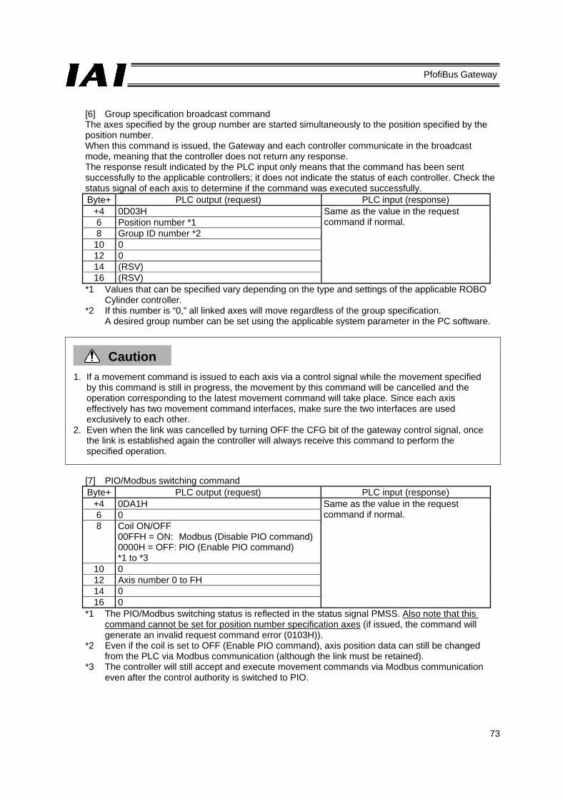
73
PfofiBus Gateway
[6] Group specification broadcast command The axes specified by the group number are started simultaneously to the position specified by the position number. When this command is issued, the Gateway and each controller communicate in the broadcast mode, meaning that the controller does not return any response. The response result indicated by the PLC input only means that the command has been sent successfully to the applicable controllers; it does not indicate the status of each controller. Check the status signal of each axis to determine if the command was executed successfully. Byte+ PLC output (request) PLC input (response)
+4 0D03H Same as the value in the request command if normal. 6 Position number *1
8 Group ID number *2 10 0 12 0 14 (RSV) 16 (RSV)
*1 Values that can be specified vary depending on the type and settings of the applicable ROBO Cylinder controller.
*2 If this number is “0,” all linked axes will move regardless of the group specification. A desired group number can be set using the applicable system parameter in the PC software.
Caution
1. If a movement command is issued to each axis via a control signal while the movement specified by this command is still in progress, the movement by this command will be cancelled and the operation corresponding to the latest movement command will take place. Since each axis effectively has two movement command interfaces, make sure the two interfaces are used exclusively to each other.
2. Even when the link was cancelled by turning OFF the CFG bit of the gateway control signal, once the link is established again the controller will always receive this command to perform the specified operation.
[7] PIO/Modbus switching command Byte+ PLC output (request) PLC input (response)
+4 0DA1H Same as the value in the request command if normal. 6 0
8 Coil ON/OFF 00FFH = ON: Modbus (Disable PIO command) 0000H = OFF: PIO (Enable PIO command) *1 to *3
10 0 12 Axis number 0 to FH 14 0 16 0
*1 The PIO/Modbus switching status is reflected in the status signal PMSS. Also note that this command cannot be set for position number specification axes (if issued, the command will generate an invalid request command error (0103H)).
*2 Even if the coil is set to OFF (Enable PIO command), axis position data can still be changed from the PLC via Modbus communication (although the link must be retained).
*3 The controller will still accept and execute movement commands via Modbus communication even after the control authority is switched to PIO.

74
PfofiBus Gateway
(4) Error response
If a command error occurs, the most significant bit (b7) of the response command will turn ON. In addition, one of the following error codes will be set in response data 1. If no link is currently formed, nothing will be shown in the response command.
Code Description
0101H Invalid address *1 0102H Invalid position number *1 0103H Invalid request command *1 0201H Communication failed 0202H Not executable by the controller
*1) If any of these conditions is found as a result of data check from the PLC, an applicable error code will be set in the response data without the data being sent to the controller.
(5) How to use commands
To use various commands, process the data in each command area according to the flow shown below. This flow assumes that only one command is processed.
Use a command
Response command area 0?
Clear the request command area and data areas 0 to 3.
Write the command code in the request command area.
Write the necessary data in data areas 0 to 3.
Response command = Request command?
Clear the request command area.
Clear data areas 0 to 3.

75
PfofiBus Gateway
6 Communication Signal Details 6.1 Overview of Communication Signal Timings When a given control signal is turned ON to operate the ROBO Cylinder using the sequence program in the PLC, the maximum response time before a response (status) signal will be received is expressed by the formula below: Maximum response time (msec) = Yt + Xt + 2 x Mt + Command processing time (operation time, etc.)
Mt = 10 (msec) x (n+1): SIO link (Modbus) cycle time n: Number of controlled axes Yt: Master → remote I/O station transmission delay Xt: Remote I/O → master station transmission delay
For the master → remote I/O station transmission delay (Yt) and remote I/O → master station transmission delay (Xt), refer to the operation manuals for your ProfiBus master unit and PLC. (Note) If a communication error occurs due to a problem along the transmission path, etc.,
a communication retry or retries (up to three times) may occur, in which case the SIO link cycle time (Mt) will be extended.
ProfiBus transmission delay
PLC sequence programControl signal
Status signal
Master → remote I/O station transmission delay (Yt)
Remote I/O → master station transmission delay (Xt)
GatewayControl signal
Status signal
ControllerControl signal
Status signal
SIO link cycle time SIO link cycle time
Response processing time

76
PfofiBus Gateway

77
PfofiBus Gateway
6.2 Communication Signals and Operation Timings (1) Controller ready (PWR) PLC input signal
This signal turns “1” (ON) when the controller becomes ready following the power on.
Function This signal turns “1” (ON) when the controller has been initialized properly following the power on and becomes ready, regardless of the alarm condition, servo status, etc. Even when an alarm is present, the PWR signal still turns “1” (ON) as long as the controller becomes ready. This signal is synchronized with the status indicator LED (green) on the front panel of the controller.
(2) Emergency stop (EMGS) PLC input signal
This signal turns “1” (ON) when the controller actuates an emergency stop.
Function This signal turns “1” (ON) when a controller alarm generates, an emergency stop is actuated by the emergency stop circuit (refer to 4.3.1), or the motor drive power is cut off. It will turn “0” (OFF) once the emergency stop is cancelled.
(3) Alarm (ALM) PLC input signal
This signal turns “1” (ON) when the controller’s protective circuit (function) detects an error.
Function This signal turns “1” (ON) when the controller’s protective circuit (function) is actuated. It will turn “0” (OFF) when the reset (RES) signal is turned “1” (ON) after removing the cause of the problem. (This is not the case with cold-start alarms.) When an alarm is detected, the ALM LED (red) on the front panel of the controller illuminates. This LED remains unlit while the controller is normal. With the ERC2-NP/PN/SE, the LED at the top of the motor unit illuminates in red. When the servo turns on, the LED changes to a steady green light.
(4) Reset (RES) PLC output signal
This signal has two functions. It can be used to reset controller alarms or cancel the remaining travel distance while the actuator is paused.
Function
[1] When an alarm is present, you can reset the alarm by removing the cause of the alarm and then turning this signal from “0” (OFF) to “1” (ON). (This is not the case with cold-start alarms.)
[2] While the actuator is paused, you can cancel the remaining travel by turning this signal from “0” (OFF) to “1” (ON).
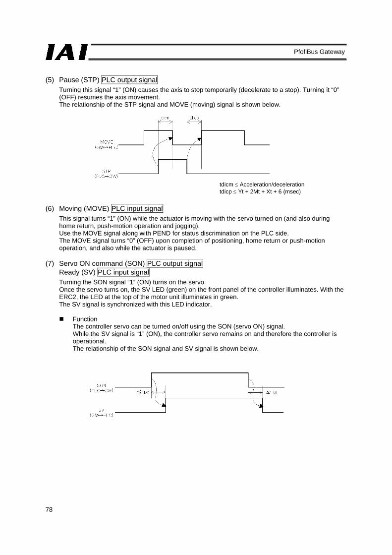
78
PfofiBus Gateway
(5) Pause (STP) PLC output signal
Turning this signal “1” (ON) causes the axis to stop temporarily (decelerate to a stop). Turning it “0” (OFF) resumes the axis movement. The relationship of the STP signal and MOVE (moving) signal is shown below.
(6) Moving (MOVE) PLC input signal
This signal turns “1” (ON) while the actuator is moving with the servo turned on (and also during home return, push-motion operation and jogging). Use the MOVE signal along with PEND for status discrimination on the PLC side. The MOVE signal turns “0” (OFF) upon completion of positioning, home return or push-motion operation, and also while the actuator is paused.
(7) Servo ON command (SON) PLC output signal
Ready (SV) PLC input signal Turning the SON signal “1” (ON) turns on the servo. Once the servo turns on, the SV LED (green) on the front panel of the controller illuminates. With the ERC2, the LED at the top of the motor unit illuminates in green. The SV signal is synchronized with this LED indicator.
Function The controller servo can be turned on/off using the SON (servo ON) signal. While the SV signal is “1” (ON), the controller servo remains on and therefore the controller is operational. The relationship of the SON signal and SV signal is shown below.
tdicm ≤ Acceleration/deceleration tdicp ≤ Yt + 2Mt + Xt + 6 (msec)

79
PfofiBus Gateway
(8) Home return command (HOME) PLC output signal
Home return complete (HEND) PLC input signal Home return operation starts at the leading edge of the HOME signal from “0” (OFF) to “1” (ON). When the home return is complete, the HEND (home return complete) signal turns “1” (ON). Turn the HOME signal “0” (OFF) after the HEND signal has turned “1” (ON). Once turned “1” (ON), the HEND signal will not turn “0” (OFF) unless the power is turned off or the HOME signal is input again. Accordingly, even after the initial home return is completed you can still perform home return as many times as desired using the HOME signal.
Caution
1. In the case of a positioner operation axis operating in the position number specification mode or command specification mode, issuing a positioning command to a given position immediately after the power was turned on, without performing the home return first, will cause the actuator to automatically return to its home and then execute the positioning, provided that this is the first operation after the power on.
2. Take note that in any other mode, an alarm “Error code 83: ALARM HOME ABS (absolute position movement command issued before completion of home return)” will generate.
Actuator operation
Mechanical end Stops at the home position.

80
PfofiBus Gateway
(9) Positioning start (CSTR) PLC output signal
Upon detecting the leading edge of this signal from “0” (OFF) to “1” (ON), the controller reads the target position number specified by the binary code of PC1 to PC32768 (the signal varies according to the operation mode), and then performs positioning to the target position corresponding to the applicable position data. The same applies when a numerical value is specified directly in the position data specification area. Before positioning is performed, the target position, speed and other operation data must be set in the position table using a PC/teaching pendant. If this command is issued before the home return operation is performed following the power on (= while the HEND output signal is “0” (OFF)), the actuator will automatically perform the home return operation and then position itself to the target position. Turn this signal “0” (OFF) after confirming that the PEND signal has turned “0” (OFF).
(10) Positioning complete (PEND) PLC input signal
This signal turns “1” (ON) when the actuator has moved to the target position and entered the positioning band, or when the push-motion operation has completed (without missing the load). If the servo has turned ON, the applicable position is set as the target position and accordingly this signal turns “1” (ON). When positioning operation is started using the HOME signal or CSTR signal thereafter, this signal will become “0” (OFF).
Caution
If the servo is turned off or an emergency stop is actuated while the actuator is stopped at the target position, the PEND signal turns “0” (OFF). When the servo subsequently turns ON, the signal will turn “1” (ON) again if the actuator is inside the positioning band. If CSTR remains “1” (ON), the PEND signal will not become “1” (ON) even when the current actuator position is inside the positioning band. The PEND signal will turn “1” (ON) when the CSTR signal turns “0” (OFF).
Speed Timing at which the positioning complete signal turns ON
Target position
Travel distance
Time
Positioning band
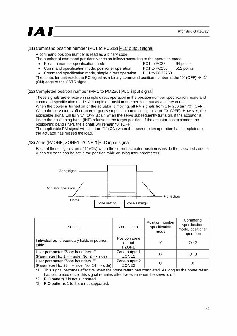
81
PfofiBus Gateway
(11) Command position number (PC1 to PC512) PLC output signal
A command position number is read as a binary code. The number of command positions varies as follows according to the operation mode: • Position number specification mode PC1 to PC32 64 points • Command specification mode, positioner operation PC1 to PC256 512 points • Command specification mode, simple direct operation PC1 to PC32768
The controller unit reads the PC signal as a binary command position number at the “0” (OFF) “1” (ON) edge of the CSTR signal.
(12) Completed position number (PM1 to PM256) PLC input signal
These signals are effective in simple direct operation in the position number specification mode and command specification mode. A completed position number is output as a binary code. When the power is turned on or the actuator is moving, all PM signals from 1 to 256 turn “0” (OFF). When the servo turns off or an emergency stop is actuated, all signals turn "0" (OFF). However, the applicable signal will turn “1” (ON)” again when the servo subsequently turns on, if the actuator is inside the positioning band (INP) relative to the target position. If the actuator has exceeded the positioning band (INP), the signals will remain “0” (OFF). The applicable PM signal will also turn “1” (ON) when the push-motion operation has completed or the actuator has missed the load.
(13) Zone (PZONE, ZONE1, ZONE2) PLC input signal
Each of these signals turns “1” (ON) when the current actuator position is inside the specified zone. *1 A desired zone can be set in the position table or using user parameters.
Setting Zone signal Position number
specification mode
Command specification
mode, positioner operation
Individual zone boundary fields in position table
Position zone output
PZONE X *2
User parameter “Zone boundary 1” (Parameter No. 1 = + side, No. 2 = - side)
Zone output 1 ZONE1 *3
User parameter “Zone boundary 2” (Parameter No. 23 = + side, No. 24 = - side)
Zone output 2 ZONE2 X
*1 This signal becomes effective when the home return has completed. As long as the home return has completed once, this signal remains effective even when the servo is off.
*2 PIO pattern 3 is not supported. *3 PIO patterns 1 to 3 are not supported.
Zone signal
Actuator operation
Home Zone setting- Zone setting+
+ direction

82
PfofiBus Gateway
(14) Jog+ command/jog- command (JOG+ / JOG-) PLC output signal
These signals are used to operate a positioner operation axis in the command specification mode under PIO pattern 1 (teaching mode). These signals are used to start jogging or inching. When the + command is issued, the actuator moves in the direction opposite home. When the – command is issued, the actuator moves in the direction of home. Jogging or inching is specified by a combination of the JOG signal and JISL signal (jogging/inching switching signal). [1] Jogging
Jogging is enabled when the jog/inch switching signal (JISL) is “0” (OFF). While JOG+ is “1” (ON), the actuator moves in the direction opposite home. When the signal turns “0” (OFF), the actuator decelerates to a stop. While JOG- is “1” (ON), the actuator moves in the direction of home. When the signal turns “0” (OFF), the actuator decelerates to a stop. The operation is set using the following parameter settings: • Speed: Defined by parameter No. 26 (PIO jog speed) • Acceleration/deceleration: Rated acceleration/deceleration (varies according to the actuator) To stop jogging (cause the actuator to decelerate to a stop), turn the current JOG signal from “1” (ON) to “0” (OFF) or cause both JOG+ and JOG- to turn “1” (ON).
[2] Inching
Inching is enabled when the jog/inch switching signal (JISL) is “1” (ON). The actuator moves by the inching distance every time the JOG signal turns from “0” (OFF) to “1” (ON). The actuator inches in the direction opposite home when JOG+ is issued, or in the direction of home if JOG- is issued. The operation is set using the following parameter settings: • Speed: Defined by parameter No. 26 (PIO jog speed) • Travel distance: Defined by parameter No. 48 (PIO inching distance) • Acceleration/deceleration: Rated acceleration/deceleration (varies according to the actuator) During normal operation, the actuator will continue with the normal operation even after the JOG+ or JOG- signal is turned “1” (ON) (= the JOG signal will be ignored). Also while the actuator is paused, the actuator will not operate even after the JOG+ or JOG- signal is turned “1” (ON) (= the JOG signal will be ignored).
Caution
Exercise caution that the actuator may collide with a mechanical end before the home return is completed, because the software stroke limits are still not effective during this period.

83
PfofiBus Gateway
(15) Jog/inch switching (JISL) PLC output signal
This signal is used to switch between jogging and inching. JISL = “0” (OFF): Jogging JISL = “1” (ON): Inching If the JISL signal switches to “1” (ON) during jogging, the accelerator will decelerate to a stop and the inching function will be enabled. If the JISL signal switches to “0” (OFF) during inching, the actuator will complete the inching and then the jogging function will be enabled. Jogging and inching commands are issued by a combination of the JISL signal and the JOG+/JOG- signal. The relationships of these signals are summarized in the table below.
Jogging Inching
JISL “0” (OFF) “1” (ON) Speed Parameter No. 26 (jog speed) Parameter No. 26 (jog speed)
Travel distance - Parameter No. 48 (inch distance) Acceleration/ deceleration
Rated value (varies according to the actuator)
Rated value (varies according to the actuator)
(16) Teaching mode command (MOD) PLC output signal
Teaching mode status (MODS) PLC input signal These signals are used when a positioner operation axis is operated in the command specification mode under PIO pattern 1 (teaching mode). When the MOD signal is turned “1” (ON), the actuator switches from the normal operation mode to the teaching mode. The controller of each axis turns the MODS signal “1” (ON) upon switching to the teaching mode. Be sure to perform teaching operation after confirming on the PLC side that the MODS signal has turned “1” (ON). *1 The following conditions must be satisfied before the actuator can be switched from the normal
operation mode to the teaching mode: • The actuator (motor) is stopped • The JOG+ signal and JOG- signal are “0” (OFF) • The position data read command (PWRT) signal and positioning start (CSTR) signal are “0”
(OFF) The PWRT signal must also be “0” (OFF) when switching from the teaching mode to the normal operation mode.

84
PfofiBus Gateway
(17) Position data read command (PWRT) PLC output signal
Position data read complete (WEND) PLC input signal These signals are used when a positioner operation axis is operated in the command specification mode under PIO pattern 1 (teaching mode). The PWRT signal is effective when the MODS signal is “1” (ON). When the PWRT signal is turned “1” (ON) for 20 msec or more (*1), the current position data will be written to the “Position” field under the position number currently specified by the PLC command. (*2) When the writing is complete, the WEND signal turns “1” (ON). The host PLC should turn the PWRT signal “0” (OFF) after the WEND signal has turned “1” (ON). If the PWRT signal is turned “0” (OFF) before the WEND signal turns “1” (ON), the WEND signal will not turn “1” (ON). When the PWRT signal is turned “0” (OFF), the WEND signal turns “0” (OFF). *1 Make sure the signal remains “1” (ON) for 20 msec or more. If the signal is turned “1” (ON) for
less than 20 msec, the data may not be written. *2 If any data other than position is not yet defined, the default value of the applicable parameter
will be written. (18) Forced brake release (BKRL) PLC output signal
You can forcibly release the brake by turning this signal “1” (ON).
20 msec or more

85
PfofiBus Gateway
6.3 Basic Operation Timings (1) Preparation
After confirming that the slider or rod is not colliding with a mechanical end or the load is not contacting any surrounding equipment, start the system by following the procedure below: [1] Cancel the emergency stop or enable the motor drive power supply. [2] Turn on the 24-VDC controller power via the 24-V terminal and 0-V terminal on the power-supply
terminal block. [3] Set the minimum required parameters.
(Example) • To change the feed speed during teaching: Change the value of parameter No. 35 (Safety speed).
[4] In the positioner mode or simple direct mode, set appropriate values in the “Position,” “Speed,” “Acceleration” and “Deceleration” fields, etc., in the position table.
Caution
When the power is turned on while an emergency stop is actuated and then the emergency stop is cancelled (= the SON signal is turned “1” (ON)), the servo will turn on up to 1.6 sec after the cancellation of the emergency stop.
Safety circuit status 24-VDC controller power supply SV lamp (front panel) Controller ready Pause Servo ON Ready Positioning complete
Emergency stop cancelled
Illuminates in orange for 2 seconds, and then turns off. Green
Default parameter setting
Pause cancelled
1.6 sec or less
Emergency stop cancelled
Servo on1.6 sec or less

86
PfofiBus Gateway
Warning
With the ACON, excited-phase detection operation is performed when the servo is turned on for the first time following the power on. Because of this detection operation, the actuator normally moves by approx. 0.5 to 2 mm, although the specific dimension varies according to the ball screw lead. (On rare occasions, the actuator may move by up to around a half of the ball screw lead depending on the actuator position when the power is turned on.) Also note that if the power is turned on while the actuator is near a mechanical end, the actuator may contact the mechanical end during the detection operation and reverse its direction as a result. Exercise due caution not to cause the load or robot hand to get damaged as a result of contact with surrounding objects during this detection operation.

87
PfofiBus Gateway
(2) Home return operation
The controller unit uses an incremental position detector (encoder), which means that once the power is cut off, the mechanical coordinates will be lost. Accordingly, home return must be performed after the power is turned on to establish the mechanical coordinates. To perform home return operation, input the home return command (HOME) signal. For your information, home return operation is not required if the simple absolute R unit is connected to the controller unit to convert the axes into absolute axes.
Operation timings PLC process 1: The home return command (HOME) signal turns “1” (ON) when the start button is
pressed. Operation: [1] The actuator starts moving toward the mechanical end on the home side.
[2] After contacting the mechanical end, the actuator reverses its direction and then stops at the home position → The home return complete (HEND) signal turns “1” (ON).
PLC process 2: The home return command (HOME) signal is turned “0” (OFF) after confirmation of the HEND signal turning “1” (ON).
PLC process 3: The actuator starts continuous operation.
Caution
Pay attention to the following points when performing home return: [1] Confirm that no obstacle exists in the direction of home return. [2] Should an obstacle be found in the direction of home return, tentatively move the actuator in the
direction opposite home and remove the obstacle. [3] Turning the HOME signal “1” (ON) turns the PEND signal “0” (OFF) and MOVE signal “1” (ON). Turn the HOME signal “0” (OFF) again after confirming that the HEND signal has turned “1” (ON) while the HOME signal is still “1” (ON).
Home return command Home return complete Positioning complete Moving Actuator movement
[1] [2]1 msec or less
Pow
er in
put
posi
tion
Mec
hani
cal e
nd
Hom
e po
sitio
n
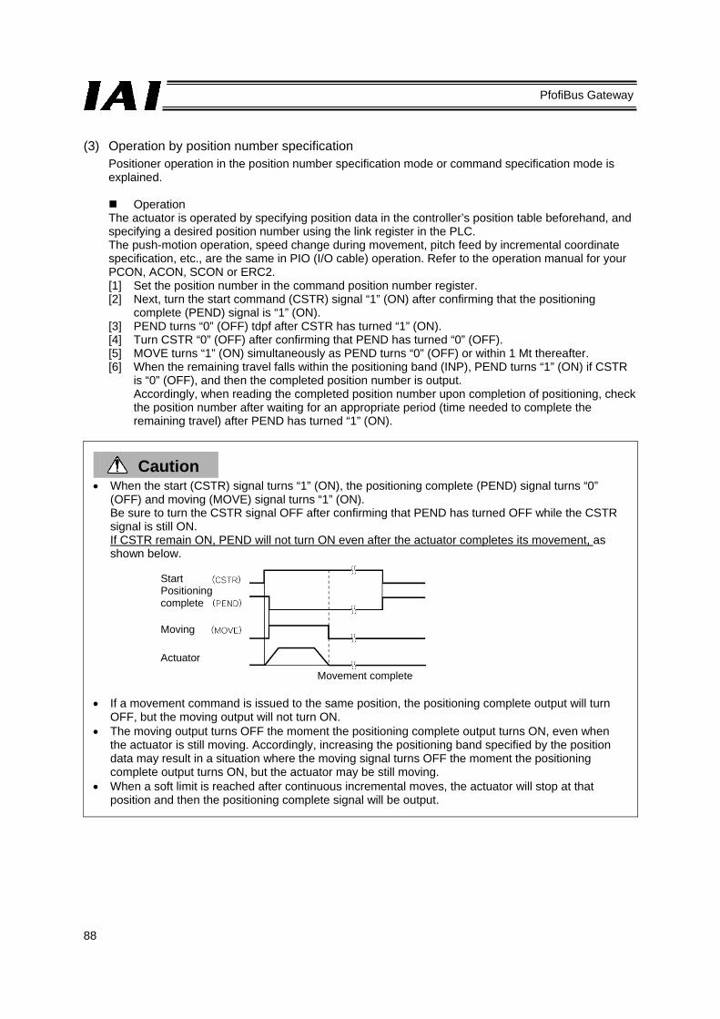
88
PfofiBus Gateway
(3) Operation by position number specification
Positioner operation in the position number specification mode or command specification mode is explained.
Operation
The actuator is operated by specifying position data in the controller’s position table beforehand, and specifying a desired position number using the link register in the PLC. The push-motion operation, speed change during movement, pitch feed by incremental coordinate specification, etc., are the same in PIO (I/O cable) operation. Refer to the operation manual for your PCON, ACON, SCON or ERC2. [1] Set the position number in the command position number register. [2] Next, turn the start command (CSTR) signal “1” (ON) after confirming that the positioning
complete (PEND) signal is “1” (ON). [3] PEND turns “0” (OFF) tdpf after CSTR has turned “1” (ON). [4] Turn CSTR “0” (OFF) after confirming that PEND has turned “0” (OFF). [5] MOVE turns “1” (ON) simultaneously as PEND turns “0” (OFF) or within 1 Mt thereafter. [6] When the remaining travel falls within the positioning band (INP), PEND turns “1” (ON) if CSTR
is “0” (OFF), and then the completed position number is output. Accordingly, when reading the completed position number upon completion of positioning, check the position number after waiting for an appropriate period (time needed to complete the remaining travel) after PEND has turned “1” (ON).
Caution • When the start (CSTR) signal turns “1” (ON), the positioning complete (PEND) signal turns “0”
(OFF) and moving (MOVE) signal turns “1” (ON). Be sure to turn the CSTR signal OFF after confirming that PEND has turned OFF while the CSTR signal is still ON. If CSTR remain ON, PEND will not turn ON even after the actuator completes its movement, as shown below.
• If a movement command is issued to the same position, the positioning complete output will turn
OFF, but the moving output will not turn ON. • The moving output turns OFF the moment the positioning complete output turns ON, even when
the actuator is still moving. Accordingly, increasing the positioning band specified by the position data may result in a situation where the moving signal turns OFF the moment the positioning complete output turns ON, but the actuator may be still moving.
• When a soft limit is reached after continuous incremental moves, the actuator will stop at that position and then the positioning complete signal will be output.
Start Positioning complete Moving Actuator
Movement complete

89
PfofiBus Gateway
*1 T1: Set T1 to 0 ms or more by considering the scan time of the host controller. *2 Yt+2Mt+Xt≤tdpf≤Yt+2Mt+Xt+7 (ms)
[1]
[2]
[3] [4]
[5]
[6]
Command position number
Start command
Positioning complete
Completed position number
Moving
90
PfofiBus Gateway
(4) Operation in the direct numerical specification mode
The actuator is operated not by using the position table of the controller, but by writing the target position data, acceleration/deceleration data, speed data, push-current limiting value data and positioning band data to the link registers in the PLC. All these data must be set in the case of push-motion operation. In the case of normal positioning operation, the push-current limiting value data, PUSH signal and DIR signal are not required. Take note that in either operation, the actuator will not move unless all necessary data is set.
Operation
[Push-motion operation] [1] Set the push start position data in the target position data specification register. [2] Set the speed data until the push start position in the speed specification register, and set the
corresponding acceleration/deceleration data in the acceleration/deceleration register. Take note that even if acceleration/deceleration is not set, the setting of parameter No. 9, “Default acceleration/deceleration” will not be applied.
[3] Set the push-motion travel in the positioning band specification register. (*) [4] Set the push-current limiting value data in the push-current limiting value register in order to set
the push force. [5] Turn the PUSH (push-motion operation mode specification) signal “1” (ON). [6] Use the DIR (push direction specification) signal to select the push direction.
When the DIR signal is set to “1” (ON), push-motion operation is performed in the direction opposite home. When the signal is set to “0” (OFF), push-motion operation is performed in the direction of home.
[7] Next, turn the start command (CSTR) signal “1” (ON) after confirming that the positioning complete (PEND) signal is “1” (ON). The data set in [1] to [4] will be read by the controller at the “0” (OFF) “1” (ON) edge of CSTR (leading edge of the signal).
[8] PEND turns “0” (OFF) tdpf after CSTR has turned “1” (ON). [9] Turn CSTR “0” (OFF) after confirming that the PEND signal has turned “0” (OFF) or MOVE
signal has turned “1” (ON). [10] MOVE turns “1” (ON) simultaneously as PEND turns “0” (OFF) or within 1 Mt thereafter. [11] PEND turns “1” (ON) when the motor current reaches the push-current limiting value set in [4]
while CSTR is “0” (OFF). (The push operation has completed.) If the motor current does not reach the push-current limiting value set in [4] even after the positioning band set in [3] has been reached, the PSFL (missed load in push operation) signal turns “1” (ON). In this case, PEND will not turn “1” (ON). (The actuator has missed the load.)
[12] The current position data is constantly refreshed. [13] Turn PUSH “0” (OFF) after PEND or PSFL has turned “1” (ON).
* Take note that even if positioning band specification data is not set, the value of parameter No. 10, “Default positioning band” will not be applied.
[Normal positioning operation]
In the case of normal operation, the operation continues while the PUSH signal is still “0” (OFF) in [5] above. Setting of push-current limiting value data in [4] is not required. PEND turns “1” (ON) when the remaining travel falls within the range of positioning band specification data set in [3], while CSTR is “0” (OFF).

91
PfofiBus Gateway
*1 T1: Set T1 to 0 ms or more by considering the scan time of the host controller.
*2 Yt+2Mt+Xt≤tdpf≤Yt+2Mt+Xt+7 (ms)
Set value of target position data
Set value of speed and acceleration/deceleration
data
Set value of positioning band data
Set value of push-current limiting value data
Push mode
Push direction
Start command
Positioning complete/missed load in push operation
Current position
Moving
[1]
[2]
[3]
[4]
[5]
[6]
[7]
[8] [9]
[13]
[12]
[11]
[10]

92
PfofiBus Gateway
The target position data, acceleration/deceleration data, speed data, positioning band data and push-current limiting value data can be changed while the actuator is moving. After a given data has been changed, turn CSTR “1” (ON) for at least tdpf. Also, after CSTR is turned “0” (OFF), wait for at least 1 Mt before turning it “1” (ON). An example of changing the speed and acceleration/deceleration data is given below.
Caution
1. If speed data is not set or the set speed is zero, the actuator will remain standstill and no alarm will generate.
2. If the speed data setting is changed to zero while the actuator is moving, the actuator will decelerate to a stop and no alarm will generate.
3. Even when only the acceleration/deceleration data or speed data is changed while the actuator is moving, the target position data must still be set.
4. Even when only the target position data is changed while the actuator is moving, the acceleration/deceleration data and speed data must still be set.
Set value of speed and acceleration/
deceleration data
Actuator speed
Speed n2
Speed n3
[1]
[2] [3]
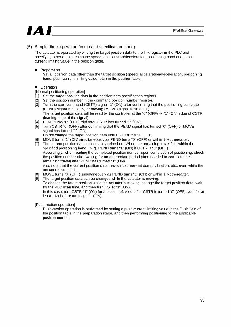
93
PfofiBus Gateway
(5) Simple direct operation (command specification mode)
The actuator is operated by writing the target position data to the link register in the PLC and specifying other data such as the speed, acceleration/deceleration, positioning band and push-current limiting value in the position table.
Preparation Set all position data other than the target position (speed, acceleration/deceleration, positioning band, push-current limiting value, etc.) in the position table.
Operation
[Normal positioning operation] [1] Set the target position data in the position data specification register. [2] Set the position number in the command position number register. [3] Turn the start command (CSTR) signal “1” (ON) after confirming that the positioning complete
(PEND) signal is “1” (ON) or moving (MOVE) signal is “0” (OFF). The target position data will be read by the controller at the “0” (OFF) “1” (ON) edge of CSTR (leading edge of the signal).
[4] PEND turns “0” (OFF) tdpf after CSTR has turned “1” (ON). [5] Turn CSTR “0” (OFF) after confirming that the PEND signal has turned “0” (OFF) or MOVE
signal has turned “1” (ON). Do not change the target position data until CSTR turns “0” (OFF).
[6] MOVE turns “1” (ON) simultaneously as PEND turns “0” (OFF) or within 1 Mt thereafter. [7] The current position data is constantly refreshed. When the remaining travel falls within the
specified positioning band (INP), PEND turns “1” (ON) if CSTR is “0” (OFF). Accordingly, when reading the completed position number upon completion of positioning, check the position number after waiting for an appropriate period (time needed to complete the remaining travel) after PEND has turned “1” (ON). Also note that the current position data may shift somewhat due to vibration, etc., even while the actuator is stopped.
[8] MOVE turns “0” (OFF) simultaneously as PEND turns “1” (ON) or within 1 Mt thereafter. [9] The target position data can be changed while the actuator is moving.
To change the target position while the actuator is moving, change the target position data, wait for the PLC scan time, and then turn CSTR “1” (ON). In this case, turn CSTR “1” (ON) for at least tdpf. Also, after CSTR is turned “0” (OFF), wait for at least 1 Mt before turning it “1” (ON).
[Push-motion operation]
Push-motion operation is performed by setting a push-current limiting value in the Push field of the position table in the preparation stage, and then performing positioning to the applicable position number.

94
PfofiBus Gateway
*1 T1: Set T1 to 0 ms or more by considering the scan time of the host controller.
*2 Yt+2Mt+Xt≤tdpf≤Yt+2Mt+Xt+7 (ms) *3 twcsON1≥Mt *4 twcsOFF≥1Mt
[1]
[2]
[3]
[4] [5]
[6]
[7]
[8]
Set value of target position data
Command position number
Start command
Positioning complete
Current position
Moving

95
PfofiBus Gateway
6.4 Command Transmission Commands can also be used in the command specification mode. A timing chart of command transmission is given below. Every time control/status data is exchanged for any of the connected axes in normal operations, the Gateway Unit analyzes each request command and responds to the command. The PLC and Gateway perform the following steps: [1] After confirming zeros in a response command, the PLC application sets the next request command
and data required. [2] After detecting non-zero data in the request command, the Gateway Unit sends the request data to
the applicable axis. [3] After receiving a response from the applicable axis, the Gateway outputs a response result. [4] After checking the response result, the PLC application clears the request command. [5] After detecting that the request command has been cleared, the Gateway clears the response
command and waits for the next command. Steps [1] through [5] are repeated in continuous command transmissions.
[1] [2]
[3]
[4]
[5]
Output of PLC request (PLC → GW)
Request command, data
Request = 0000H
Transmission to/from the controller is performed by
the Gateway
Gateway response Response = 0000H
Response command, data

96
PfofiBus Gateway
7. Building Your Network System 7.1 Procedure The procedure to start a ProfiBus network using the gateway unit is explained below.
(1) Installation Install the ProfiBus gateway unit, each axis controller and other necessary units in the control panel.
(2) Wiring Wire the gateway unit’s 24-V power supply and field network, and also wire for SIO communication, etc. (Refer to Section 4.)
(3) Setting the axis number for each axis controller (Refer to 4.3.2 and 7.2.) Setting the SIO baud rate for each axis controller (Refer to 7.2.)
(4) Setting the baud rate, node address and mode setting switch for the gateway unit (Refer to 2.3 and 7.3.)
(5) Setting the node address and baud rate and assigning the master PLC address for the ProfiBus master (Refer to 7.3 and 7.4.)
(6) Creating a controller position table
(7) Creating a PLC ladder sequence

97
PfofiBus Gateway
7.2 Setting the Controller For the controller to be able to communicate with the Gateway, the settings specified below must be performed. (1) Setting the axis number
Set an axis number in a range of 0 to 15 by avoiding duplication. Take note that the range of settable axis numbers varies depending on the operation mode of the Gateway Unit. The setting procedure using a PC (PC software) is explained below. For details, refer to the operation manual for the PC (PC software) or teaching pendant. [1] Connect a PC (in which the PC software is installed) or teaching pendant to the gateway unit*,
and turn the port switch ON. [2] Start the PC software. [3] Click Settings (S), and then select Controller Settings. [4] Click Assign Axis Number (N). [5] When the axis number assignment table appears, set a desired number. [6] Click OK, and then press ESC. [7] Connect/disconnect each SIO link cable and set the axis number for the next controller. [8] Finally when all axis numbers have been set, connect all axes to the SIO link.
* • Link via SIO only the axes you want to set. In other words, connect only the applicable axes to
the 4-way junctions. Plug/unplug each connector as you set each axis. • You can also set each applicable axis by disconnecting one by one from the SIO link only the
axes you want to set and then connecting a PC or teaching pendant directly to the connector.

98
PfofiBus Gateway
(2) Setting the SIO baud rate
Set the applicable controller parameter using the PC software or teaching pendant in the same manner as in (1). [1] Set parameter No. 16, “SIO baud rate” to “230400” (230.4 kbps).
SIO communication cannot be performed at any baud rate other than 230.4 kbps. [2] Set parameter No. 17, “Minimum slave transmitter activation delay” to “5” or less.
Set this parameter to “0” if you want to use the fastest communication cycle. The figure shows the user parameter setting screen of the PC software.

99
PfofiBus Gateway
7.3 Setting the Gateway Unit and PLC Master For the Gateway Unit to be able to communicate with the master station, the settings specified below must be performed. The following items must be consistent between the master station and the Gateway Unit.
: ON X: OFF Item Gateway Unit setting PLC master setting
Baud rate Set automatically according to the corresponding setting of
the host PLC master
Baud rate setting switch
Node address Node address setting switch Node address setting
switch
Assignments
No. Mode setting switch SW1 Occupied area setting
4 3 2 1 Output (bytes)
Input (bytes)
1 X X X X 52 28 Direct numerical specification mode, 4 axes
2 X X X 76 40 Direct numerical specification mode, 6 axes
3 X X X 100 52 Direct numerical specification mode, 8 axes
4 X 124 64 Direct numerical specification mode, 10 axes
5 X X 196 100 Direct numerical specification mode, 16 axes *
6 X X X 48 48 Position number specification mode, 16 axes
7 X X X 160 160 Command specification mode, Large 8 X X 128 128 Command specification mode, Middle 9 X X 64 64 Command specification mode, Small
* When connecting 10 or more axes, the PLC must be the S7-400 or S7-318-2 (Siemens). (1) Setting the ProfiBus baud rate
[1] Gateway unit side The baud rate need not be set, because it is set automatically according to the corresponding setting of the host PLC master.
[2] PLC master side Use the baud rate setting switch on the master unit. (Refer to the PLC operation manual.)
(2) Node address
[1] Gateway unit side Use the node address setting switch. (Refer to 2.3.) Normally this switch is set to 3 or greater.
[2] PLC master side Use the node address setting switch. (Refer to the PLC operation manual.) Normally this switch is set to 2.
(3) Setting the gateway unit mode
Set the operation mode of the gateway unit using the mode setting switch SW1. (Refer to 2.3.) This setting determines the I/O sizes of the gateway unit. Accordingly register the mode as part of the slave I/O assignment settings in the master. (Refer to 7.4.)

100
PfofiBus Gateway
7.4 PLC Address Assignment (1) Installing a GSD file
The following explanation assumes use of STEP7 HardWare Configuration by Siemens (hereinafter referred to as “HW Config”). Before defining the gateway, download the GSD file for the gateway. The GSD file you need is hms_1003.gsd. It can be downloaded from IAI’s website. Start the HW Config software and install the GSD file you have downloaded. Select Options from the menu bar, and then click Install New GSD from the pull-down menu.
< GSD file import>
When the GSD file has been imported successfully, a new level called “ANYBUS-PDP” will be created in the catalog window of the HW Config screen, as shown below.
<Catalog window showing the imported GSD file>

101
PfofiBus Gateway
(2) Inserting a ProfiBus-DP mater system
Select Insert from the menu bar, select Master System from the pull-down menu, and then click DP. Select the ProfiBus-DP master to insert the master system.
<Master system insertion>
When the ProfiBus-DP master has been inserted successfully, it will be displayed as the master system, as shown below.
<After the ProfiBus-DP master system has been inserted>

102
PfofiBus Gateway
(3) Inserting a Gateway rack in the network
Drag and drop “ANYBUS-S PDP” in the catalog window over to the master system and insert it as a module, as shown below. The address will be set automatically. To change the address that has been set automatically, do so in the Properties dialog box. This address must correspond to the address switch setting of the Gateway, as mentioned earlier.
<Rack insertion into the network> (4) Setting the I/O assignments – Inserting a universal module
Insert a universal module into the rack inserted in the previous step, as shown below. Since the maximum input/output bytes of the universal module are 64 each, another universal module must be inserted if there are 10 or more axes.
<Universal module insertion into the rack>

103
PfofiBus Gateway
Double-clicking the inserted universal module will open the Properties dialog box shown below. Select “Out-input” under I/O Type, and enter appropriate values under Output Length and Input Length according to the occupied area information in the table in 7.3. The example below applies to a 4-axis system operated in the direct numerical specification mode. Since the addresses are set automatically, change them if necessary.
<I/O length settings for the universal module>
Click the OK button, and the settings will be reflected in the universal module as shown below.
<Universal module with its I/O lengths set>
All settings are now complete. You can now download them to the PLC.

104
PfofiBus Gateway
(5) Setting for I/O data consistency
With normal settings, consistency of ProfiBus I/O data is guaranteed in units of words and bytes. It is important that each command code and related parameters in the command area are read or written together. To ensure consistent data access, an applicable item must be set to ensure data consistency in the HW Config screen, and data must be accessed using the SFC14 and SFC15. With command function blocks, the first five words in the command area are accessed using the SFC14/15. Accordingly, the data consistency setting must be performed in the I/O areas for the applicable five words, as shown in the example below.
Double-click a desired line or select Object Propertiesin the pull-down menu.
Set “Total length,” instead of a unit (Byte or Word) under Consistent over.

105
PfofiBus Gateway
(6) Actual assignment example
If the mode setting switch SW1 on the gateway unit is turned OFF (direct numerical specification mode, 4 axes) for all axes, performing the I/O assignment explained in the preceding section would result in the actual addresses looking like those specified below.
The S7-300 PLC guarantees consistency of I/O image and data at the data width (byte, word or double words) defined in the program. If data consistency must be guaranteed throughout the I/O areas, one way is to copy/write the I/O areas to the memory area (M area) using system function blocks SFC14 and SFC15, and then specify the M area in the program. For details on this method, refer to the applicable document published by HMS: http://www.anybus.com/eng/upload/AnyBus-S-0012-Siemens%20Step7%20and%20AnyBus-S.pdf
PLC output
Gateway control word 0 Gateway control word 1 Axis (0) target position
Axis (0) push rate Axis (0) speed
Axis (0) acceleration/deceleration
Axis (0) in-position band Axis (0) control signal
Axis (1) target position Axis (1) push rate
Axis (1) speed Axis (1) acceleration/deceleration
Axis (1) in-position band Axis (1) control signal
Axis (2) target position Axis (2) push rate
Axis (2) speed Axis (2) acceleration/deceleration
Axis (2) in-position band Axis (2) control signal
Axis (3) target position Axis (3) push rate
Axis (3) speed Axis (3) acceleration/deceleration
Axis (3) in-position band Axis (3) control signal
PLC input
Gateway status word 0 Gateway status word 1
Axis (0) status signalAxis (0) current position
Cannot be used.
Cannot be used. Axis (1) status signal
Axis (1) current position Cannot be used.
Cannot be used. Axis (2) status signal
Axis (2) current position Cannot be used.
Cannot be used. Axis (3) status signal
Axis (3) current position Cannot be used.
Cannot be used.
Based on the above, the control signals, status signals, direct specification data and current position of axis (3) will be addressed as shown in the table below.
Output signal/data Address Data length Address Data length Input signal/data nameTarget position Push rate Speed Acceleration/deceleration In-position band
3 bytes 1 byte 3 bytes
1 byte 3 bytes 1 bit 1 bit 1 bit 1 bit 1 bit 1 bit 1 bit 1 bit
1 bit 1 bit 1 bit 1 bit 1 bit 1 bit 1 bit 1 bit 3 bytes Current position

106
PfofiBus Gateway
8. Supported S7 Function Blocks/Functions The function blocks (FB)/functions (FC) provided by IAI allow for easy programming without the need to worry about detailed I/O assignments. The basic functions provided include this addressing function and a range check function for certain input parameters. These function blocks/functions can be utilized only with the Siemens S7 Series. Short sample programs are provided in the appendix for reference. The following function blocks/functions are supported. *2, *3
Name Overview Note
GW CTL ** Start/stop Gateway-controller communication and specify a linked axis.
RC NVC ** Execute movement by numerical specification.
RC ESYNC ** Execute movement by simple numerical specification.
RC BCMOVP ** Broadcast a movement start command. *1
RC READ ** Read RC data (POS table data, current position, alarm code). *1
RC WRITE ** Write RC data (POS table data). *1
RC PROM ** Convert position data into ROM. *1
RC PMSL ** Switch between PIO and Modbus. *1
*1) Use only one of these function blocks at a time, as they all access the same area. These function blocks control command transmission, but do not monitor the response time. The response time must be monitored by the application if necessary.
*2) In the common input parameter LADDR, set the Gateway I/O head addresses
set in HW Config. The initial input and output address numbers must be the same, and the address numbers must be consecutive.
*3) All function blocks/functions use address register 1 (AR1). Exercise caution if this
register is used by the application.

107
PfofiBus Gateway
8.1 GW_CTL_11
Explanation; This is a function to access Gateway control/status words. Before calling other function block/function, communication between the Gateway and the controller must be started using this function. Axis configuration must also be defined in the ProfiBus module.
Parameters; I/O Parameter name
Data type Explanation
Input MON BOOL Start Gateway-controller communication. CFG WORD Specify an axis to be actually configured using a bit
pattern (bit 0 = Axis 0, bit 15 = Axis 15). NPS INT Number of axes used in the POS-number
specification movement mode. Axis numbers are assigned from 0 based on this value, and the direct numerical specification mode becomes effective for all remaining areas. *1
PPS INT PIO pattern number in the POS-number specification movement mode *1
LADDR WORD Output Gateway head I/O addresses for output Output GW_STS WORD Gateway status word 0 is output.
LNKS WORD Gateway status word 1 is output. *1 This setting is effective only when the mode setting switch is set to 0x1, 0x5 and 0x9.
Modbus communication start
Axis configuration definition word
Number of POS mode axes
POS-mode PIO pattern number
Gateway head address
Gateway status
Axis link status

108
PfofiBus Gateway
8.2 RC_NVC_11
Explanation; SV, VELO, ADCC, INP and PROW are transferred from the Gateway to the controller at the leading edge of MREQ, and executed. Other parameters are always effective when this function block is called. For example, even if MREQ is OFF, calling this function block during home return will change the applicable output parameters in accordance with the home return operation.
Parameters; I/O Parameter name
Data type Explanation
Input MREQ BOOL Issue a movement request upon FALSE → TRUE. SON BOOL Servo on command HOME BOOL Home return command PUSH BOOL Push mode, if TRUE DIR BOOL Push direction (0 = Home return direction, 1 = Opposite to home
return direction) STOP BOOL Pause command ALMRS BOOL Alarm reset command SV DINT Target position (Set value) SPEED DINT Speed ADCC INT Acceleration/deceleration INP DINT In-position band (Push band, if PUSH is ON) PPOW WORD Push rate (Effective, if PUSH is ON) LADDR INT Gateway head I/O address AXIS INT Axis number (0 to 15)
Output RDY BOOL Controller ready SERVO BOOL Servo status HEND BOOL Home return status ALM BOOL Alarm status EMG BOOL Emergency stop status DONE BOOL One pulse is output upon completion of movement (PEND or
PSFL leading edge pulse). MOVE BOOL Moving, if TRUE AERR WORD The value of AXIS exceeds 15 or negative, or LADDR is negative. PV DINT Current position (Process value)
Move requestServo on
Home returnPush-motion operation
Push directionPause
Alarm resetTarget position
SpeedAcceleration/deceleration
In-position bandPush rate
Gateway head addressAxis number
Controller ready Servo status Home return status Alarm status Emergency stop status Movement complete pulse Moving Address error Current position

109
PfofiBus Gateway
8.3 RC_ESYNC_00
Explanation; SV and PARA_N are transferred from the Gateway to the controller at the leading edge of MREQ, and executed. Other parameters are always effective when this function block is called. For example, even if MREQ is OFF, calling this function block during home return will change the applicable output parameters in accordance with the home return operation.
Parameters; I/O Parameter name Data type Explanation
Input MREQ BOOL Issue a movement request upon FALSE → TRUE. SON BOOL Servo on command HOME BOOL Home return command SV DINT Target position (Set value) PARA_N INT Movement parameter (POS) number STOP BOOL Pause command ALMRS BOOL Alarm reset command LADDR INT Gateway head I/O address AXIS INT Axis number (0 to 15)
Output RDY BOOL Controller ready SERVO BOOL Servo status HEND BOOL Home return status ALM BOOL Alarm status EMG BOOL Emergency stop status DONE BOOL One pulse is output upon completion of movement (PEND or
PSFL leading edge pulse). MVES BOOL Movement start pulse
(PEND or PSFL trailing edge pulse). PV DINT Current position (Process value) AERR WORD The value of AXIS exceeds 15 or negative, or LADDR is
negative.
Controller ready
Servo status
Home return status
Alarm status
Emergency stop status
Movement complete pulse
Movement start pulse
Current position
Address error
Move requestServo on
Home returnTarget position
Movement parameternumber
PauseAlarm reset
Gateway head addressAxis number

110
PfofiBus Gateway
8.4 RC_BCMOVP_00
Explanation; The Gateway broadcasts the start command for the specified POS to the specified group at the leading edge of REQ. The execution complete pulse of this function block indicates that issuance of this command has completed, not that movement of each axis has completed. To check if each axis has completed its movement, check the status bit of each axis.
Parameters; I/O Parameter name
Data type Explanation
Input REQ BOOL Issue an execution request upon FALSE → TRUE. POS WORD Position number value. Settable values vary
depending on the axis. GROUP BYTE Group ID number LADDR WORD Gateway head I/O address
Output DONE BOOL One pulse is output upon completion of command issuance.
BUSY BOOL The command is being issued. RESULT WORD Command issuance
result code; 0000H Successful 0102H Invalid POS number 0103H Invalid command 0201H Communication failed 0202H Exceptional response
* This function block uses the SFC14/15. Consistency setting is required for data corresponding to the first five words in the command area.
Move request
POS number
Group number
Gateway head address
Issuance complete pulse
Executing
Result code

111
PfofiBus Gateway
8.5 RC_READ_00
Explanation; The data specified by POS and DATA_ID is read from the specified axis at the leading edge of REQ. The input parameter POS is effective only when the data type ID is one that relates to the POS table.
Parameters; I/O Parameter name Data type Explanation
Input REQ BOOL Issue an execution request upon FALSE → TRUE. POS INT Position number value. Settable values vary
depending on the axis. DATA_ID INT Data type ID; 0 Target position (unit: 0.01 mm)
1 In-position band (unit: 0.01 mm) 2 Speed (unit: 0.01 mm/s) 3 Each zone+ (unit: 0.01 mm) 4 Each zone- (unit: 0.01 mm) 5 Acceleration (unit: 0.01 G) 6 Deceleration (unit: 0.01 G) 7 Push rate (FFH = 100%) 8 Threshold % (FFH = 100%) 128 Current Position 129 Alarm code
LADDR WORD Gateway head I/O address AXIS BYTE Axis number (0 to 15)
Output DONE BOOL One pulse is output upon completion of command issuance.
BUSY BOOL The command is being issued. RESULT WORD Command
issuance result code;
0000H Successful 0102H Invalid POS number 0103H Invalid command 0201H Communication failed 0202H Exceptional response 1000H Invalid axis number or data ID
DATE DWORD Read data * This function block uses the SFC14/15. Consistency setting is required for data corresponding to the
first five words in the command area.
Read request
Position number
Data type ID
Gateway head address
Axis number
Complete pulse
Executing
Result code
Read data

112
PfofiBus Gateway
8.6 RC_WRITE_00
Explanation; The data specified by POS and DATA_ID is written to the specified axis at the leading edge of REQ.
Parameters; I/O Parameter name Data type Explanation
Input REQ BOOL Issue an execution request upon FALSE → TRUE. POS INT Position number value. Settable values vary
depending on the axis. DATA_ID INT Data type ID; 0 Target position
1 In-position band 2 Speed 3 Each zone+ (DATA: unit: 0.01 mm) 4 Each zone- (DATA: unit: 0.01 mm) 5 Acceleration (DATA: unit: 0.01 G) 6 Deceleration (DATA: unit: 0.01 G) 7 Push rate (DATA: FFH = 100%) 8 Threshold % (DATA: FFH = 100%)
DATA DWORD Write data LADDR WORD Gateway head I/O address AXIS BYTE Axis number (0 to 15)
Output DONE BOOL One pulse is output upon completion of command issuance.
BUSY BOOL The command is being issued. RESULT WORD Command
issuance result code;
0000H Successful 0102H Invalid POS number 0103H Invalid command 0201H Communication failed 0202H Exceptional response 1000H Invalid axis number or data ID
* This function block uses the SFC14/15. Consistency setting is required for data corresponding to the first five words in the command area.
Write request
Position number
Data type ID
Write data
Gateway head address
Axis number
Complete pulse
Executing
Result code
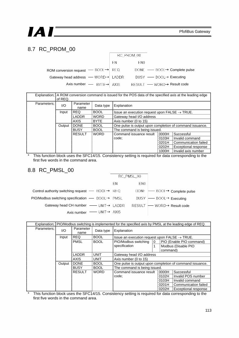
113
PfofiBus Gateway
8.7 RC_PROM_00
Explanation; A ROM conversion command is issued for the POS data of the specified axis at the leading edge of REQ.
Parameters; I/O Parameter name Data type Explanation
Input REQ BOOL Issue an execution request upon FALSE → TRUE. LADDR WORD Gateway head I/O address AXIS BYTE Axis number (0 to 15)
Output DONE BOOL One pulse is output upon completion of command issuance. BUSY BOOL The command is being issued. RESULT WORD Command issuance result
code; 0000H Successful 0103H Invalid command 0201H Communication failed 0202H Exceptional response 1000H Invalid axis number
* This function block uses the SFC14/15. Consistency setting is required for data corresponding to the first five words in the command area.
8.8 RC_PMSL_00
Explanation; PIO/Modbus switching is implemented for the specified axis by PMSL at the leading edge of REQ. Parameters; I/O Parameter
name Data type Explanation
Input REQ BOOL Issue an execution request upon FALSE → TRUE. PMSL BOOL PIO/Modbus switching
specification 0 PIO (Enable PIO command) 1 Modbus (Disable PIO
command) LADDR UNIT Gateway head I/O address AXIS UNIT Axis number (0 to 15)
Output DONE BOOL One pulse is output upon completion of command issuance. BUSY BOOL The command is being issued. RESULT WORD Command issuance result
code; 0000H Successful 0102H Invalid POS number 0103H Invalid command 0201H Communication failed 0202H Exceptional response
* This function block uses the SFC14/15. Consistency setting is required for data corresponding to the first five words in the command area.
ROM conversion request
Gateway head address
Axis number
Complete pulse
Executing
Result code
Control authority switching request
PIO/Modbus switching specification
Gateway head CH number
Axis number
Complete pulse
Executing
Result code

114
PfofiBus Gateway
Appendix 1. Sample Programs for S7-300 Example of Using RC_NVC_11 and GW_CTL_11
#AnyON is always ON.
GW/controller communication starts (MON).
Axis 0 is configured (W#16#1).
The Gateway I/O head addresses are “0.”
Servo on delay timer
Homing delay timer
The next target position is controlled based on the movement completion pulse (NC0.DONE) output by a FB. The target position changes in the sequence of x0p1 → x0p2 → x0p3 → x0p1, …, every time the NC0.DONE pulse is input.
Online status is checked from the STS_W, LNK_W and RC_NVC_11 (instance name: NC0) outputs.

115
PfofiBus Gateway
Step1 movement data set (push motion) Target position: 30.00 mm Speed: 100.00 mm/s Acceleration/deceleration: 0.2 Push band: 20.00 mm Push rate: 49% (7F / FF)
Step2 movement data set (normal movement) Target position: 20.00 mm Speed: 100.00 mm/s Acceleration/deceleration: 0.2 Positioning band: 00.10 mm Push rate: 0%
Step3 movement data set (normal movement) Target position: 00.00 mm Speed: 100.00 mm/s Acceleration/deceleration: 0.2 Positioning band: 00.10 mm Push rate: 0%
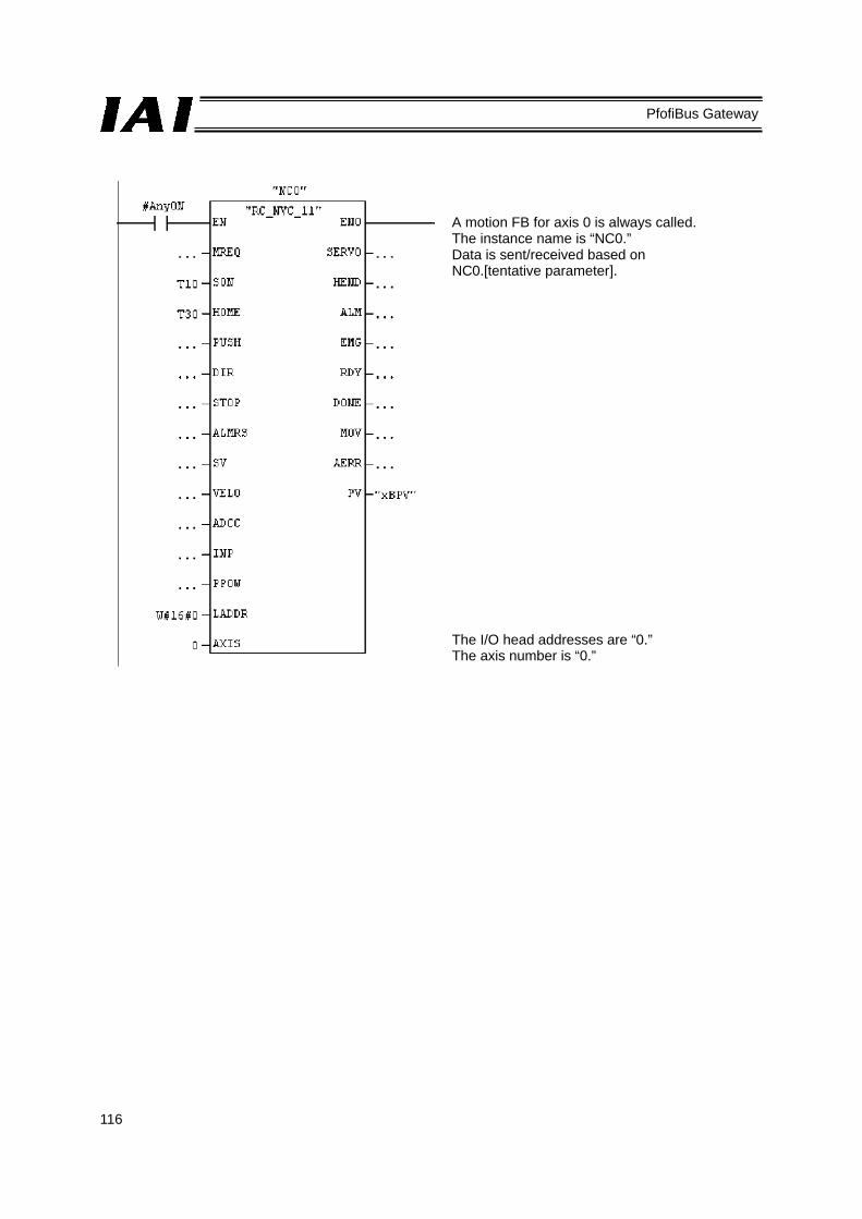
116
PfofiBus Gateway
A motion FB for axis 0 is always called. The instance name is “NC0.” Data is sent/received based on NC0.[tentative parameter].
The I/O head addresses are “0.” The axis number is “0.”

117
PfofiBus Gateway
Appendix 2. Supply Format and Use Procedure of FB/FCt FBs are provided as source files ([Function block name_Version].AWL). The steps to use a provided source file in a user project are explained below.
[1] Select the “Sources” folder, click Insert, and then click External Source....
[2] When the following file selection window opens, select an appropriate source file, and then click Save.
[3] The source file will be imported to the “Sources” folder.

118
PfofiBus Gateway
[4] Start Symbol Editor, and save the FB RC_NVC under a desired FB number.
[5] Compile the source file.
[6] When the compiling is complete, the registered function block will be generated in the “Blocks” folder.
Now, FB1, namely RC_NVC, can be called from OB1.

Manual No.: ME0177-2B (October 2014)
The information contained in this document is subject to change without notice for purposes of product improvement.Copyright © 2014. Oct. IAI Corporation. All rights reserved.
14.10.000
Head Office: 577-1 Obane Shimizu-KU Shizuoka City Shizuoka 424-0103, JapanTEL +81-54-364-5105 FAX +81-54-364-2589
website: www.iai-robot.co.jp/
Ober der Röth 4, D-65824 Schwalbach am Taunus, GermanyTEL 06196-88950 FAX 06196-889524
SHANGHAI JIAHUA BUSINESS CENTER A8-303, 808, Hongqiao Rd. Shanghai 200030, ChinaTEL 021-6448-4753 FAX 021-6448-3992
website: www.iai-robot.com
Technical Support available in USA, Europe and China
Head Office: 2690 W. 237th Street, Torrance, CA 90505TEL (310) 891-6015 FAX (310) 891-0815
Chicago Office: 110 East State Parkway, Schaumburg, IL 60173TEL (847) 908-1400 FAX (847) 908-1399
TEL (678) 354-9470 FAX (678) 354-9471website: www.intelligentactuator.com
Atlanta Office: 1220 Kennestone Circle, Suite 108, Marietta, GA 30066