professional foundations - wiley
TRANSCRIPT

P A R T
IProfessional Foundations
3927 P-01 7/10/02 9:22 AM Page 1

3927 P-01 7/10/02 9:22 AM Page 2

c h a p t e r
1THE OFFICE
3927 P-01 7/10/02 9:22 AM Page 3
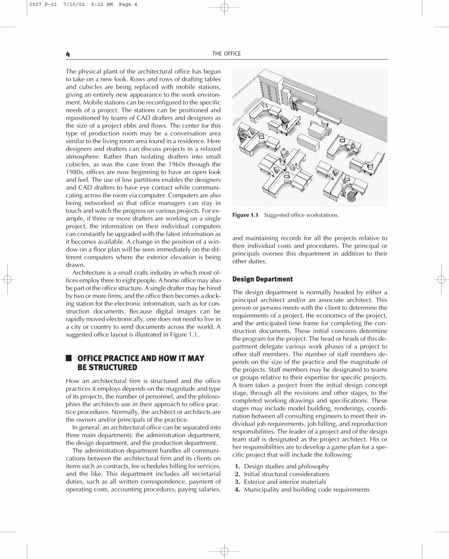
The physical plant of the architectural office has begunto take on a new look. Rows and rows of drafting tablesand cubicles are being replaced with mobile stations,giving an entirely new appearance to the work environ-ment. Mobile stations can be reconfigured to the specificneeds of a project. The stations can be positioned andrepositioned by teams of CAD drafters and designers asthe size of a project ebbs and flows. The center for thistype of production room may be a conversation areasimilar to the living room area found in a residence. Heredesigners and drafters can discuss projects in a relaxedatmosphere. Rather than isolating drafters into smallcubicles, as was the case from the 1960s through the1980s, offices are now beginning to have an open lookand feel. The use of low partitions enables the designersand CAD drafters to have eye contact while communi-cating across the room via computer. Computers are alsobeing networked so that office managers can stay intouch and watch the progress on various projects. For ex-ample, if three or more drafters are working on a singleproject, the information on their individual computerscan constantly be upgraded with the latest information asit becomes available. A change in the position of a win-dow on a floor plan will be seen immediately on the dif-ferent computers where the exterior elevation is beingdrawn.
Architecture is a small crafts industry in which most of-fices employ three to eight people. A home office may alsobe part of the office structure. A single drafter may be hiredby two or more firms, and the office then becomes a dock-ing station for the electronic information, such as for con-struction documents. Because digital images can berapidly moved electronically, one does not need to live ina city or country to send documents across the world. Asuggested office layout is illustrated in Figure 1.1.
OFFICE PRACTICE AND HOW IT MAYBE STRUCTURED
How an architectural firm is structured and the officepractices it employs depends on the magnitude and typeof its projects, the number of personnel, and the philoso-phies the architects use in their approach to office prac-tice procedures. Normally, the architect or architects arethe owners and/or principals of the practice.
In general, an architectural office can be separated intothree main departments: the administration department,the design department, and the production department.
The administration department handles all communi-cations between the architectural firm and its clients onitems such as contracts, fee schedules billing for services,and the like. This department includes all secretarialduties, such as all written correspondence, payment ofoperating costs, accounting procedures, paying salaries,
and maintaining records for all the projects relative totheir individual costs and procedures. The principal orprincipals oversee this department in addition to theirother duties.
Design Department
The design department is normally headed by either aprincipal architect and/or an associate architect. Thisperson or persons meets with the client to determine therequirements of a project, the economics of the project,and the anticipated time frame for completing the con-struction documents. These initial concerns determinethe program for the project. The head or heads of this de-partment delegate various work phases of a project toother staff members. The number of staff members de-pends on the size of the practice and the magnitude ofthe projects. Staff members may be designated to teamsor groups relative to their expertise for specific projects.A team takes a project from the initial design conceptstage, through all the revisions and other stages, to thecompleted working drawings and specifications. Thesestages may include model building, renderings, coordi-nation between all consulting engineers to meet their in-dividual job requirements, job billing, and reproductionresponsibilities. The leader of a project and of the designteam staff is designated as the project architect. His orher responsibilities are to develop a game plan for a spe-cific project that will include the following:
1. Design studies and philosophy2. Initial structural considerations3. Exterior and interior materials4. Municipality and building code requirements
4 THE OFFICE
Figure 1.1 Suggested office workstations.
3927 P-01 7/10/02 9:22 AM Page 4

5. If applicable, architectural committee reviews6. Building equipment requirements7. Manufacturing resources8. Selection of required engineering consultants such
as; soils/geology, structural, mechanical, etc.9. Planned man-hours, time sheets and billing dates
10. Office standards relative to the representation ofitems on the working drawings such as; symbols,wall delineations, and other graphic depictions
Production Department
The production department, while supervised by a pro-ject architect, prepares all the phases for a set of com-pleted working drawings. Working drawings may beproduced by senior draftpersons, intermediate draftper-sons, or junior draftpersons. These staff members and theproject architect or job captain work as a team to makethe transition from the approved preliminary drawings tothe implementation and completion of the workingdrawings. The transition from the approved preliminarydrawings to the development of the working drawings iselaborated in Chapter 6 of this book. Other chapters pro-vide step-by-step procedures on how different sections ofthe working drawings are developed: the site and grad-ing plan, foundation plan, floor plan, building sections,exterior elevations, roof and framing plans, interior ele-vations, architectural details and schedules. During theprocess and completion of the various sections, the pro-ject architect and/or job captain constantly review thedrawings for clarity, accuracy, craftsmanship of detailing,and to see that the drawings reflect all current revisions.These drawings are either created with the use of acomputer-aided drafting (CAD) system or are drawnmanually using conventional instruments. A suggestedorganizational chart for the practice of architecture is de-picted in Figure 1.2.
RESOURCES
To accommodate all the equipment that is required for astructure, such as plumbing, hardware, finishes, and soforth, it is necessary to have access to the various manu-facturing resources for specific products. The most widelyused product information source is the Sweet’s CatalogFile. This file is provided in a set of volumes that allowarchitects and engineers to select the equipment neces-sary for the function of a building. Such equipment maybe available from various manufacturers of conveyingsystems, window and doors, and the like. Information onthe various products is now contained on CD-ROMs,which are easier to manipulate than the larger volumes.There are a number of electronic files that can beobtained. The CDs are based on the Uniform Construc-
RESOURCES 5
Figure 1.2 Suggested office organizational chart.
ARCHITECT / PRICIPAL / OWNER
DesignAdministration Production
tion Index, used widely in the construction industry.These particular systems use the following sixteen majordivisions:
1. General data2. Site work3. Concrete4. Masonry5. Metals6. Wood and plastics7. Thermal and moisture protection8. Doors and windows9. Finishes
10. Specialties11. Equipment12. Furnishing13. Special construction14. Conveying systems15. Mechanical16. Electrical
Research via the Computer
Almost every large manufacturer has a web site that youcan visit via the Internet. One can now research anythingfrom hardware to framing anchors, engineered lumberproducts to composite building products. Research forbuilding products is done in the same fashion as researchfor a term paper. The scope of such research can beworldwide. You are limited only by your ability to navi-gate through the sea of information and your ability to re-trieve the necessary information that will satisfy andenhance the completion of the working drawings.
3927 P-01 7/10/02 9:22 AM Page 5

Most manufacturers also provide the architect with avideo explaining a product, its specifications, and instal-lation. Digital drawings can also be obtained, making itunnecessary to draw configurations for products such aswindow sections, stairs, and the like.
Manufacturers’ Literature
A wealth of product information is available directlyfrom manufacturers in the form of brochures, pamphlets,catalogs, manuals, and hardbound books. Actual sam-ples of their products may also be obtained. The infor-mation available can include the following:
1. Advantages of a particular product over others2. How the system works or is assembled3. Necessary engineering4. Detailed drawings5. Special design features6. Colors, textures, and patterns7. Safety tests8. Dimensioning9. Installation procedures
Other Reference Sources
Retail sources such as major book publishers produce ar-chitectural reference books. Many art supply and draft-ing supply stores also carry reference materials. Publiclibraries contain a variety of professional reference ma-terials—books, journals, and magazines. Colleges anduniversities offering architecture courses have architec-tural resource materials. These may include a broad gen-eral coverage of such areas as architectural drafting,graphics, engineering, and design principles. An exam-ple of a highly technical resource is the AIA ArchitecturalGraphics Standards published by John Wiley & Sons.This book includes the maximum, minimum, and aver-age sizes for a variety of items and contains such diverseinformation as the size of a baseball diamond or a bowl-ing alley, the dimensions of most musical instruments,and the standard sizes for most major kitchen utensilsand appliances. This book is found in almost all archi-tectural offices.
Guides and Indexes
Two invaluable general book indexes are the SubjectGuide to Books in Print (author and title volumes) andthe Reader’s Guide to Periodical Literature. All majorbookstores carry these annual reference books. TheReader’s Guide to Periodical Literature is excellent for lo-cating magazine articles on specific building types, newbuilding techniques, and works of specific architects.Four additional sources of architectural information are
the Art Index, Applied Science and Technology, TheHumanities Index, and the Social Science Index. Theseare available in most college and university libraries andin major public libraries.
PROFESSIONAL ORGANIZATIONS
Professional organizations can be an asset to the businessperformance and office functions of an architectural firm.The American Institute of Architects (AIA) is an exampleof a professional organization that will provide memberswith recommended documents, including client and ar-chitect contractual agreements, client and contractoragreements, and many others. The institution also pro-vides recommended guidelines relative to fee schedulesand disbursements, construction document facets, build-ing specifications, and construction observation proce-dures and documentation.
Ethical procedures and office practice methods arerecommended and defined as part of the many docu-ments that are available from the American Institute ofArchitects.
It is recommended that associate architects and em-ployees at the various technical levels become involvedwith a professional organization for a number of reasons,including being made aware of current technical infor-mation and activities within the profession of architect.The AIA also offers programs and directions for those inan internship phase of their careers. Student associatemember programs are available through the AIA whichprovide an overall view of the architectural profession.
Other professional organizations for students of archi-tecture can be found in their respective colleges anduniversities.
ARCHITECT/CLIENT RELATIONSHIP
The relationship between the architect and the client,and the procedures for building a project, will varyamong architectural offices as different architecturalphilosophies may be practiced.
In general, the architect/client relationship for a specificbuilding project and the necessary responsibilities andprocedures to accomplish the goals of the project will beinitiated with the selection of the architect. After the ar-chitect is selected, the architect and the client enter intoa contract, which defines the services to be performedand the responsibilities of the architect and the client. Inmany states it is a requirement that the architect use awritten contract when providing professional services.
After the contractual agreement is signed and a re-tainer fee is given, the architect reviews the building siteand confers with the client to determine the goals of the
6 THE OFFICE
3927 P-01 7/10/02 9:22 AM Page 6
ARCHITECT/CLIENT RELATIONSHIP 7
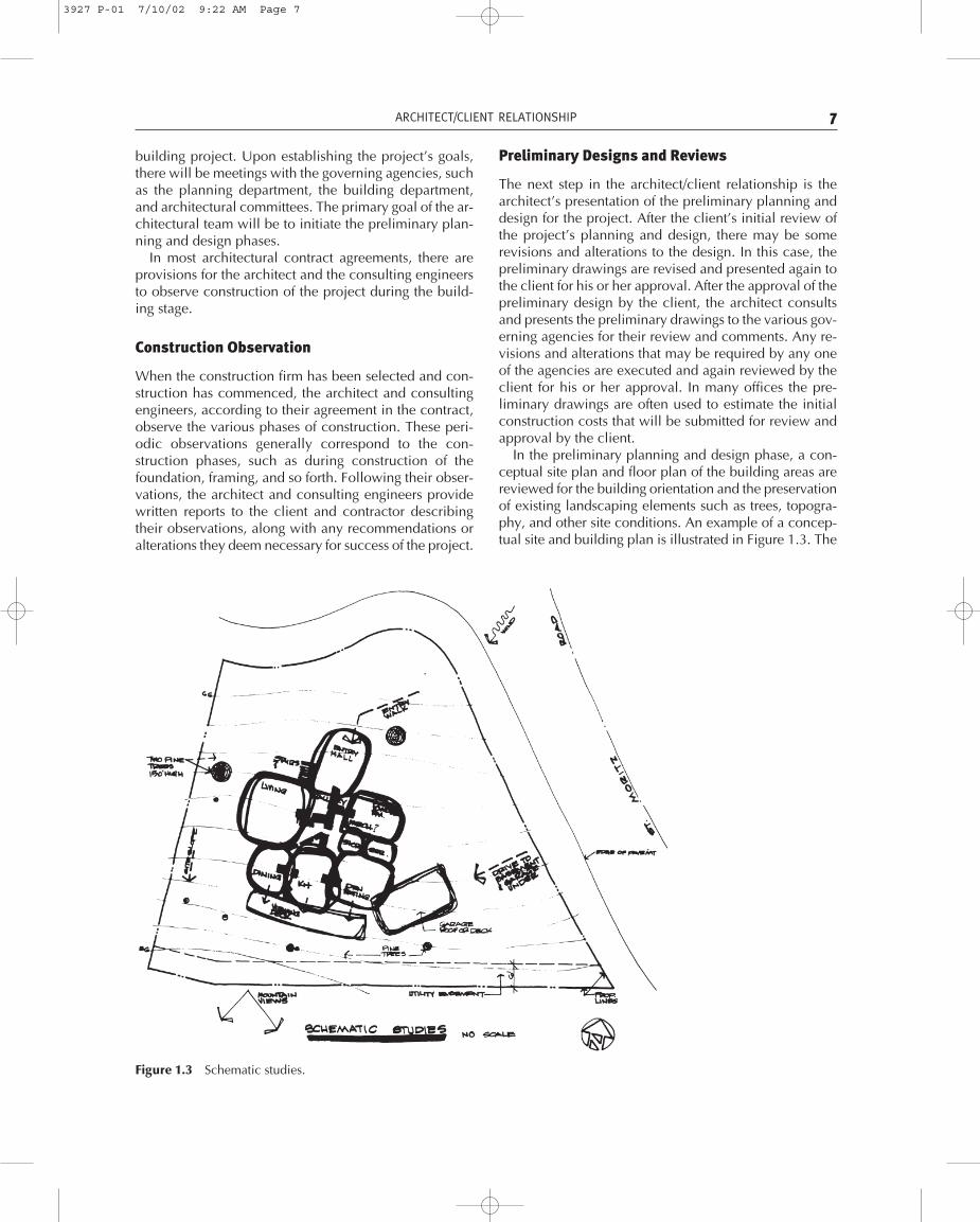
Figure 1.3 Schematic studies.
building project. Upon establishing the project’s goals,there will be meetings with the governing agencies, suchas the planning department, the building department,and architectural committees. The primary goal of the ar-chitectural team will be to initiate the preliminary plan-ning and design phases.
In most architectural contract agreements, there areprovisions for the architect and the consulting engineersto observe construction of the project during the build-ing stage.
Construction Observation
When the construction firm has been selected and con-struction has commenced, the architect and consultingengineers, according to their agreement in the contract,observe the various phases of construction. These peri-odic observations generally correspond to the con-struction phases, such as during construction of thefoundation, framing, and so forth. Following their obser-vations, the architect and consulting engineers providewritten reports to the client and contractor describingtheir observations, along with any recommendations oralterations they deem necessary for success of the project.
Preliminary Designs and Reviews
The next step in the architect/client relationship is thearchitect’s presentation of the preliminary planning anddesign for the project. After the client’s initial review ofthe project’s planning and design, there may be somerevisions and alterations to the design. In this case, thepreliminary drawings are revised and presented again tothe client for his or her approval. After the approval of thepreliminary design by the client, the architect consultsand presents the preliminary drawings to the various gov-erning agencies for their review and comments. Any re-visions and alterations that may be required by any oneof the agencies are executed and again reviewed by theclient for his or her approval. In many offices the pre-liminary drawings are often used to estimate the initialconstruction costs that will be submitted for review andapproval by the client.
In the preliminary planning and design phase, a con-ceptual site plan and floor plan of the building areas arereviewed for the building orientation and the preservationof existing landscaping elements such as trees, topogra-phy, and other site conditions. An example of a concep-tual site and building plan is illustrated in Figure 1.3. The
3927 P-01 7/10/02 9:22 AM Page 7

client for this project desires to build a three-bedroom res-idence for a young family. The site is located in a moun-tain area that is subject to heavy snow conditions. Twolarge pine trees are on the site, which are to be retained.
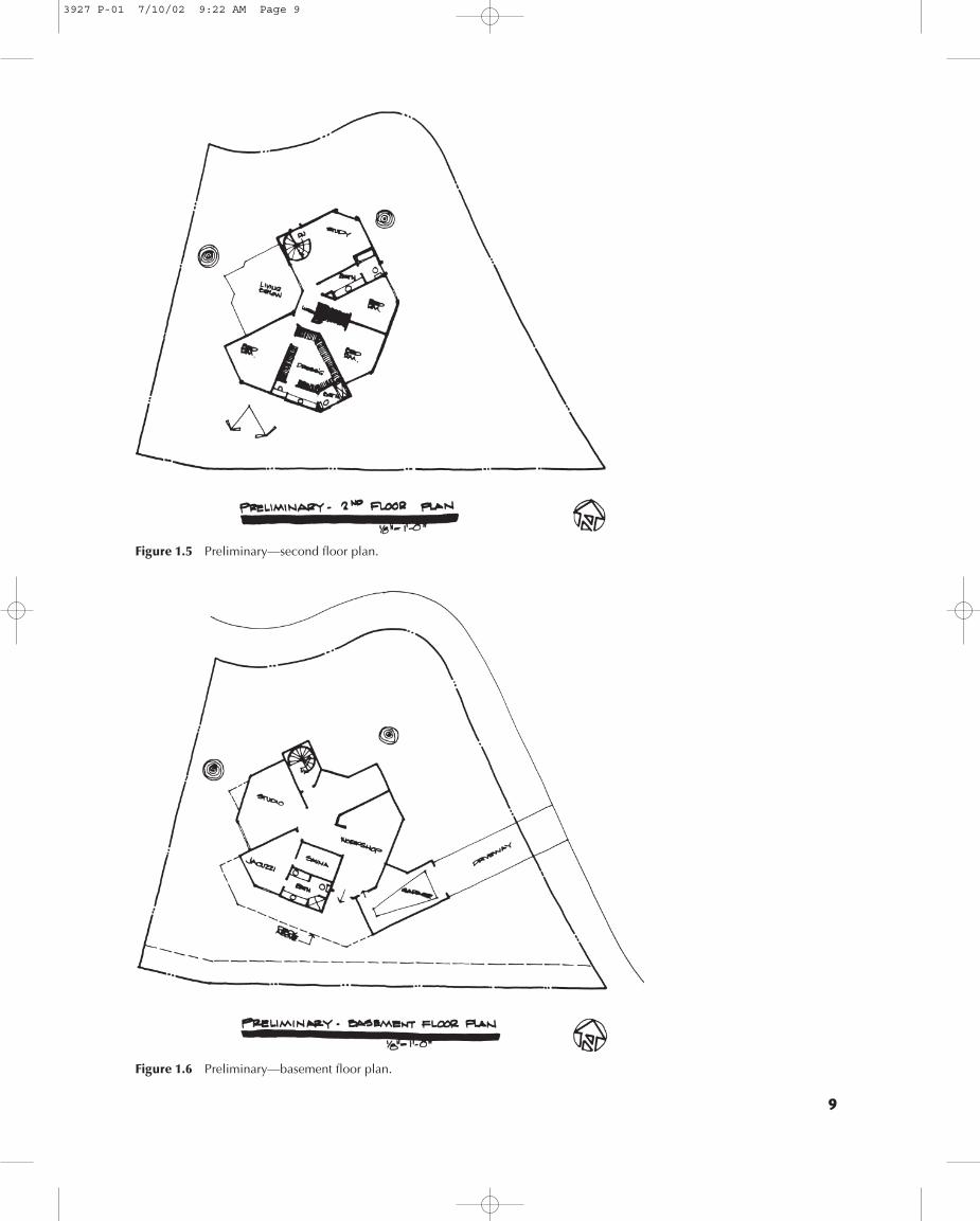
Besides the large pine trees, the mountain views, winddirection, and the most feasible automobile access to thesite are considered, and a schematic study is presented.From this initial schematic study a preliminary floor planis established, which shows the room orientations andtheir relationships to one another. This preliminary draw-ing is depicted in Figure 1.4. A second floor level pre-liminary plan is studied as it relates to the first floor planand the room orientation as shown in Figure 1.5. Finally,a basement floor plan is designed to facilitate the use ofan artist’s studio and a cabinet workshop. This prelimi-nary study is illustrated in Figure 1.6. The studies of theexterior elevations evolved utilizing an insulated alu-minum roof material, with a steep pitched roof, and ex-terior walls of wood siding. The unusual shape of theresidence required studies of the roof plan for geometricsolutions. As developed from these studies, a roof plan is
shown in Figure 1.7. After the client has approved thepreliminary floor plans, the exterior elevations for theNorth and West are presented in preliminary form tothe client for approval, and to the governmental agenciesfor their required approvals. The North and West eleva-tions are depicted in Figures 1.8 and 1.9. These prelimi-nary drawings and designs are but examples of thearchitect’s studies that may be presented to the client forhis or her approval prior to implementation of the work-ing drawings.
IMPLEMENTATION OF THE WORKINGDRAWINGS
After approval of the preliminary designs and planningfor a project by the client and governing agencies, thearchitect’s office initiates the working drawing phase forthe construction of the project.
During the working drawing phase a team of architectsconsult with the engineers required on a specific project.
8 THE OFFICE
Figure 1.4 Preliminary—first floor plan.
3927 P-01 7/10/02 9:22 AM Page 8
9
Figure 1.6 Preliminary—basement floor plan.
Figure 1.5 Preliminary—second floor plan.
3927 P-01 7/10/02 9:22 AM Page 9

10
Figure 1.8 North exterior conceptualdesign.
Figure 1.9 West exterior conceptual design.
Figure 1.7 Roof plan—conceptual design.
3927 P-01 7/10/02 9:22 AM Page 10

Consulting engineers may be employed directly by thearchitect, or they may have their own private practice.These consultants may include a soils and geologicalengineer, a structural engineer, a mechanical engineer,an electrical engineer, and a civil engineer. Other con-sultants may include a landscape architect and a costestimator. Periodic conferences with the client are rec-ommended during this phase in order to attain approvalson the various phases of the working drawings. Thesephases or stages may include lighting and electricaldesigns, interior cabinetry, wall designs, and many otherfeatures that may necessitate review and approval bythe client. If these drawings are being developed by useof a CAD system, refer to Chapter 3 for recommendedprocedures.
Materials and Specifications
There will be numerous conferences between the archi-tect and the client during the working drawing phase toselect and determine items such as exterior and interiorwall finishes, flooring, plumbing fixtures, hardwaredesign, type of masonry, roofing materials, and so on.During these conferences, the selection of buildingequipment and systems are also reviewed and deter-mined. The equipment selection may include such itemsas types of windows and doors and the manufacturer, theelevator type and manufacturer, the mechanical system,electrical fixtures, and so on. Refer to Chapter 6 for re-lated information on the aforementioned items.
Finalization of the Working Drawingsand Specifications
Upon completion of the working drawings and specifi-cations, which are now termed construction documents,the architect and/or client may submit the constructiondocuments to financing institutions for building loans, tovarious construction firms for building cost proposals,and to governing agencies for their final approvals. Fi-nally, the architectural firm will be responsible for sub-mitting the construction documents to the local buildingdepartment for its approval to obtain the required build-ing permits.
At the completion of the project, the architect and hisor her consultants make a final inspection of the con-struction of the building and prepare what is termed a“punch list.” This punch list is in written form and in-cludes graphics indicating to the client and constructionfirm any revisions, reports, or alterations they deem per-tinent and reasonable for a successful building project.After the construction firm makes the revisions, thearchitect and the consultants again inspect the revisionsfor approval. If acceptable, a final notice of approval issent to the client and the construction firm.
BUILDING
Building Codes
The purpose of building codes is to safeguard life, health,and the public welfare. Building codes are continuallybeing revised and incorporating additional regulationsbased on tests or conditions caused by catastrophicevents, such as hurricanes, earthquakes, and fires. Inmost cases, the governing building codes are similar inorganization and context. The following building codeexamples and portions are derived from the current edi-tion of the Uniform Building Code.
Building Code Divisions Primarily, the Uniform Build-ing Code is divided into eleven parts with specific chap-ters and sections incorporated into the various parts. Thevarious parts are as follows:
Part I AdministrationPart II Definitions and AbbreviationsPart III Requirements Based on OccupancyPart IV Requirements Based on Types of
ConstructionPart V Engineering Regulations—Quality and
Design of the Materials of ConstructionPart VI Detailed RegulationsPart VII Fire-Resistive Standards for Fire ProtectionPart VIII Regulations for Use of Public Streets and
Projections over Public PropertyPart IX Wall and Ceiling CoveringsPart X Special SubjectsPart XI Uniform Building Code Standards
The requirements of various agencies and codes are ofparamount influence in the design and detailing oftoday’s structures. There are a great number of codesthat govern and regulate the many elements that are in-tegrated into the construction of a building. The majorcodes that are used in the design and detailing of build-ings are the building code, mechanical code, electricalcode, fire code, energy code, and accessibility designcriteria for persons with disabilities.
Procedures for Use of the Building Codes There are anumber of governing building code requirements thatdictate the architectural designs an architect or designerwill incorporate in developing a design for a specificstructure. For example, to establish the design programfor a proposed two-story building having a floor area of10,000 square feet per floor, it will be necessary to re-view the governing building code to determine the vari-ous requirements that dictate a major portion of thedesign criteria. The following are the primary steps usedin most building codes to determine the classificationand requirements for a specific structure.
BUILDING 11
3927 P-01 7/10/02 9:22 AM Page 11
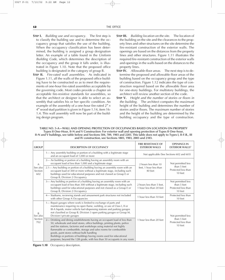
STEP I. Building use and occupancy. The first step isto classify the building use and to determine the oc-cupancy group that satisfies the use of the building.When the occupancy classification has been deter-mined, the building is assigned a group designationletter. An example of a table found in the UniformBuilding Code, which determines the description ofthe occupancy and the group it falls under, is illus-trated in Figure 1.10. Note that the proposed officebuilding is designated in the category of group B.
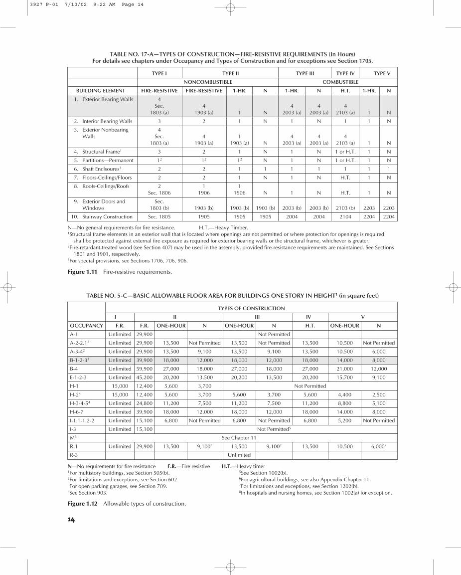
STEP II. Fire-rated wall assemblies. As indicated inFigure 1.11, all the walls of the proposed office build-ing have to be constructed so as to meet the require-ments of one-hour fire-rated assemblies acceptable bythe governing code. Most codes provide a chapter onacceptable fire-resistive standards for assemblies, sothat the architect or designer is able to select an as-sembly that satisfies his or her specific condition. Anexample of the assembly of a one-hour fire-rated 2″ ×4″ wood stud partition is given in Figure 1.14, item 16-1.4. This wall assembly will now be part of the build-ing design program.
STEP III. Building location on the site. The location ofthe building on the site and the clearances to the prop-erty lines and other structures on the site determine thefire-resistant construction of the exterior walls. Theopenings are based on the distances from the propertylines and other structures. Figure 1.11 illustrates therequired fire-resistant construction of the exterior wallsand openings in the walls based on the distances to theproperty lines.
STEP IV. Allowable floor areas. The next step is to de-termine the proposed and allowable floor areas of thebuilding based on the occupancy group and the typeof construction. Figure 1.12 indicates the type of con-struction required based on the allowable floor areafor one-story buildings. For multistory buildings, thearchitect will review another section of the code.
STEP V. Height and the number of stories or floors inthe building. The architect computes the maximumheight of the building and determines the number ofstories and/or floors. The maximum number of storiesand the height of the building are determined by thebuilding occupancy and the type of construction.
12 THE OFFICE
TABLE NO. 5-A—WALL AND OPENING PROTECTION OF OCCUPANCIES BASED ON LOCATION ON PROPERTYTypes II One-Hour, II-N and V Construction: For exterior wall and opening protection of Types II One-hour,
II-N and V buildings, see table below and Sections 504, 709, 1903 and 2203. This table does not apply to Types I, II-F.R., IIIand IV construction, see Sections 1803, 1903, 2003 and 2103.
Figure 1.10 Occupancy description.
FIRE RESISTANCE OF OPENINGS INGROUP DESCRIPTION OF OCCUPANCY EXTERIOR WALLS EXTERIOR WALLS1
1— Any assembly building or portion of a building with a legitimate stageand an occupant load of 1,000 or more
Not applicable (See Sections 602 and 603)
2— An building or portion of a building having an assembly room with an
A occupant load of less than 1,000 and a legitimate stage 2 hours less than 10 Not permitted less
See also 2.1— Any building or portion of a building having an assembly room with an feet, 1 hour less than than 5 feet
Section occupant load of 300 or more without a legitimate stage, including such 40 feet Protected less than
602 buildings used for educational purposes and not classed as Group E or 10 feet
Group B, Division 2 Occupancy
3— Any building or portion of a building having an assembly room with an Not permitted less occupant load of less than 300 without a legitimate stage, including such 2 hours less than 5 feet, than 5 feetbuildings used for educational purposes and not classed as a Group E or 1 hour less than 20 feet Protected less thanGroup B, Division 2 Occupancy 10 feet
4— Stadiums, reviewing stands and amusement park structures not included Protected less thanwith other Group A Occupancies
1 hour less than 10 feet10 feet
1— Repair garages where work is limited to exchange of parts andmaintenance requiring no open flame, welding, or use of Class I, II orIII-A liquids, motor vehicle fuel-dispensing stations and parking garages
B not classified as Group B, Division 3 open parking garages or Group M,See also Division I private garages Not permitted less Section 2— Drinking and dining establishments having an occupant load of less than 1 hour less than 20 feet than 5 feet
702 50, wholesale and retail stores, office buildings, printing plants, police Protected less than
and fire stations, factories and workshops using material not highly 10 feet
flammable or combustible, storage and sales rooms for combustiblegoods, paint stores without bulk handlingBuildings or portions of buildings having rooms used for educationalpurposes, beyond the 12th grade, with less than 50 occupants in any room
3927 P-01 7/10/02 9:22 AM Page 12

TABLE NO. 5-A—ContinuedTYPES II ONE-HOUR, II-N AND V ONLY
Figure 1.10 Occupancy description (continued).
1Openings shall be protected by a fire assembly having at least a three-fourths-hour fire-protection rating.2Group E, Divisions 2 and 3 Occupancies having an occupant load of not more than 20 may have exterior wall and opening protection as
required for Group R, Division 3 Occupancies.3For agricultural buildings, see Appendix Chapter 11.NOTES: (1) See Section 504 for types of walls affected and requirements covering percentage of openings permitted in exterior walls.
(2) For additional restrictions, see chapters under Occupancy and Types of Construction(3) For walls facing yards and public ways, see Part IV.
FIRE RESISTANCE OF OPENINGS INGROUP DESCRIPTION OF OCCUPANCY EXTERIOR WALLS EXTERIOR WALLS1
3— Aircraft hangars where no repair work is done except exchange of partsNot permitted less
and maintenance requiring no open flame, welding, or the use of Class Ithan 5 feet
B or II liquids 1 hour less than 20 feetProtected less than
(Cont.) Open parking garages (For requirements, see Section 709)20 feet
Helistops
4— Ice plants, power plants, pumping plants, cold storage and creameriesFactories and workshops using noncombustible and nonexplosivematerial 1 hour less than 5 feet
Not permitted less
Storage and sales rooms of noncombustible and nonexplosive materialsthan 5 feet
that are not packaged or crated in or supported by combustible material
1— Any building used for educational purposes through the 12th grade by 50or more persons for more than 12 hours per week or four hours in any one
E dayNot permitted less
See also 2— Any building used for educational purposes through the 12th grade by 2 hours less than 5 feet,than 5 feet
Section less than 50 persons for more than 12 hours per week or four hours in any 1 hour less thanProtected less than
802 one day 10 feet210 feet2
3— Any building or portion thereof used for day-care purposes for more thansix persons
H See Table No. 9-C
1.1— Nurseries for the full-time care of children under the age of six (eachaccommodating more than five persons)
I Hospitals, sanitariums, nursing homes with nonambulatory patients Not permitted less
See also similar buildings (each accommodating more than five persons) 2 hours less than 5 feet than 5 feet
Section 1.2— Health-care centers for ambulatory patients receiving outpatient 1 hour elsewhere Protected less than
1002 medical care which may render the patient incapable of unassisted 10 feet
self-preservation (each tenant space accommodating more than five suchpatients)
2— Nursing homes for ambulatory patients, homes for children six years of 1 hour
Not permitted less age of over (each accommodating more than five persons) than 5 feet
3— Mental hospitals, mental sanitariums, jails, prisons, reformatories and 2 hours less than 5 feet. Protected less thanbuildings where personal liberties of inmates are similarly restrained 1 hour elsewhere 10 feet
1— Private garages, carports, sheds and agricultural buildings 1 hour less than 3 feetM3 (or may be protected
See also on the exterior with Not permitted less Section materials approved for than 3 feet1102 1-hour fire-resistive
construction)
2— Fences over 6 feet high, tanks and towers Not regulated for fire resistance
R 1— Hotels and apartment houses Not permitted less See also Congregate residences (each accommodating more than 10 persons)
1 hour less than 5 feetthan 5 feet
Section 3— Dwellings and lodging houses, congregate residences (each Not permitted less 1202 accommodating 10 persons or less)
1 hour less than 3 feetthan 3 feet
BUILDING 13
3927 P-01 7/10/02 9:22 AM Page 13
14
TABLE NO. 17-A—TYPES OF CONSTRUCTION—FIRE-RESISTIVE REQUIREMENTS (In Hours) For details see chapters under Occupancy and Types of Construction and for exceptions see Section 1705.
Figure 1.11 Fire-resistive requirements.
N—No general requirements for fire resistance. H.T.—Heavy Timber.1Structural frame elements in an exterior wall that is located where openings are not permitted or where protection for openings is required
shall be protected against external fire exposure as required for exterior bearing walls or the structural frame, whichever is greater.2Fire-retardant-treated wood (see Section 407) may be used in the assembly, provided fire-resistance requirements are maintained. See Sections
1801 and 1901, respectively.3For special provisions, see Sections 1706, 706, 906.
TYPE I TYPE II TYPE III TYPE IV TYPE V
NONCOMBUSTIBLE COMBUSTIBLE
BUILDING ELEMENT FIRE-RESISTIVE FIRE-RESISTIVE 1-HR. N 1-HR. N H.T. 1-HR. N
1. Exterior Bearing Walls 4Sec. 4 4 4 4
1803 (a) 1903 (a) 1 N 2003 (a) 2003 (a) 2103 (a) 1 N
2. Interior Bearing Walls 3 2 1 N 1 N 1 1 N
3. Exterior Nonbearing 4Walls Sec. 4 1 4 4 4
1803 (a) 1903 (a) 1903 (a) N 2003 (a) 2003 (a) 2103 (a) 1 N
4. Structural Frame1 3 2 1 N 1 N 1 or H.T. 1 N
5. Partitions—Permanent 12 12 12 N 1 N 1 or H.T. 1 N
6. Shaft Enclsoures3 2 2 1 1 1 1 1 1 1
7. Floors-Ceilings/Floors 2 2 1 N 1 N H.T. 1 N
8. Roofs-Ceilings/Roofs 2 1 1Sec. 1806 1906 1906 N 1 N H.T. 1 N
9. Exterior Doors and Sec.Windows 1803 (b) 1903 (b) 1903 (b) 1903 (b) 2003 (b) 2003 (b) 2103 (b) 2203 2203
10. Stairway Construction Sec. 1805 1905 1905 1905 2004 2004 2104 2204 2204
TABLE NO. 5-C—BASIC ALLOWABLE FLOOR AREA FOR BUILDINGS ONE STORY IN HEIGHT1 (in square feet)
Figure 1.12 Allowable types of construction.
N—No requirements for fire resistance F.R.—Fire resistive H.T.—Heavy timer1For multistory buildings, see Section 505(b). 5See Section 1002(b).2For limitations and exceptions, see Section 602. 6For agricultural buildings, see also Appendix Chapter 11.3For open parking garages, see Section 709. 7For limitations and exceptions, see Section 1202(b).4See Section 903. 8In hospitals and nursing homes, see Section 1002(a) for exception.
TYPES OF CONSTRUCTION
I II III IV V
OCCUPANCY F.R. F.R. ONE-HOUR N ONE-HOUR N H.T. ONE-HOUR N
A-1 Unlimited 29,900 Not Permitted
A-2-2.12 Unlimited 29,900 13,500 Not Permitted 13,500 Not Permitted 13,500 10,500 Not Permitted
A-3-42 Unlimited 29,900 13,500 9,100 13,500 9,100 13,500 10,500 6,000
B-1-2-33 Unlimited 39,900 18,000 12,000 18,000 12,000 18,000 14,000 8,000
B-4 Unlimited 59,900 27,000 18,000 27,000 18,000 27,000 21,000 12,000
E-1-2-3 Unlimited 45,200 20,200 13,500 20,200 13,500 20,200 15,700 9,100
H-1 15,000 12,400 5,600 3,700 Not Permitted
H-24 15,000 12,400 5,600 3,700 5,600 3,700 5,600 4,400 2,500
H-3-4-54 Unlimited 24,800 11,200 7,500 11,200 7,500 11,200 8,800 5,100
H-6-7 Unlimited 39,900 18,000 12,000 18,000 12,000 18,000 14,000 8,000
I-1.1-1.2-2 Unlimited 15,100 6,800 Not Permitted 6,800 Not Permitted 6,800 5,200 Not Permitted
I-3 Unlimited 15,100 Not Permitted5
M6 See Chapter 11
R-1 Unlimited 29,900 13,500 9,1007 13,500 9,1007 13,500 10,500 6,0007
R-3 Unlimited
3927 P-01 7/10/02 9:22 AM Page 14

15
TABLE NO. 5-D—MAXIMUM HEIGHT OF BUILDINGS
Figure 1.13 Maximum building heights.
TYPES OF CONSTRUCTION
I II III IV V
OCCUPANCY F.R. F.R. ONE-HOUR N ONE-HOUR N H.T. ONE-HOUR N
MAXIMUM HEIGHT IN FEET
Unlimited 160 65 55 65 55 65 50 40
MAXIMUM HEIGHT IN FEET
A-1 Unlimited 4 Not Permitted
A-2-2.1 Unlimited 4 2 Not Permitted 2 Not Permitted 2 2 Not Permitted
A-3-41 Unlimited 12 2 1 2 1 2 2 1
B-1-2-32 Unlimited 12 4 2 4 2 4 3 2
B-4 Unlimited 12 4 2 4 2 4 3 2
E3 Unlimited 4 2 1 2 1 2 2 1
H-14 1 1 1 1 Not Permitted
H-24 Unlimited 2 1 1 1 1 1 1 1
H-3-4-54 Unlimited 5 2 1 2 1 2 2 1
H-6-7 3 3 3 2 3 2 3 3 1
I-1.15-1.2 Unlimited 3 1 Not Permitted 1 Not Permitted 1 1 Not Permitted
I-2 Unlimited 3 2 Not Permitted 2 Not Permitted 2 2 Not Permitted
I-3 Unlimited 2 Not Permitted6
M7 See Chapter 11
R-1 Unlimited 12 4 28 4 28 4 3 28
R-3 Unlimited 3 3 3 3 3 3 3 3
TABLE NO. 43-B—RATED FIRE-RESISTIVE PERIODS FOR VARIOUS WALLS AND PARTITIONS
Figure 1.14 Fire-resistive wall assemblies (continued).
MINIMUM FINISHED THICKNESS
ITEMFACE-TO-FACE2
MATERIAL NUMBER CONSTRUCTION 4 Hr. 3 Hr. 2 Hr. 1 Hr.
15. Nonum-bustibleStuds— No. 16 gauge approved nailable metal studs10 24" on center with full-lengthInterior
15-1.35⁄8" Type X gypsum wallboard7 applied vertically and nailed 7" on center with
47⁄8Partition with 6d cement-coated common nails. Approved metal fastener grips used withGypsum nails at vertical butt joints along studs.
WallboardEach Side
2" × 4" wood studs 16" on center wiht two layers of 3⁄8" regular gypsumwallboard7 each side. 4d cooler12 or wallboard12 nails at 8" on center first
16-1111 16 layer, 5d cooler12 or wallboard12 nails at 8" on center second layer with 5laminating compound between layers. Joints staggered. First layer aplied
16. Woodfull length vertically, second layer applied horizontally or vertically.
Studs— 2" × 4" wood studs 16" on center with two layers 1⁄2" regular gypsumInterior
16-1.211 16 wallboard7 applied vertically or horizontally each side, joints staggered. Nail51⁄2
Partition with base layer with 5d cooler12 or wallboard12 nails at 8" on center, face layer withGypsum 8d cooler12 or wallboard12 nails at 8" on center.
Wallboard2" × 4" wood studs 24" on center with 5⁄8" Type X gypsum wallboard7 aplied Each Side
16.1.311 16 vertically or horizontally nailed with 6d cooler12 or wallboard12 nails at 7" on 43⁄4center with end joints on nailing members. Stagger joints each side.
2" × 4" fire-retardant-treated wood studs spaced 24" on center with one layer
16-1.411 of 5⁄8" thick Type X gypsum wallboard7 applied with face paper grain (longdimension) paralell to studs. Wallboard attached with 6d cooler12 orwallboard12 nails at 7" on center.
3927 P-01 7/10/02 9:22 AM Page 15

16 THE OFFICE
Figure 1.13 illustrates what will be required for the var-ious design criteria. The shaded areas illustrated inFigures 1.10, 1.11, l.12, and 1.13 are applicable to aproposed two-story office building.
Code Influence on Building Design
An example of code-related design requirements is pro-vided by the site plan for the proposed two-story officebuilding. The architect desires that all four sides of thebuilding have windows. To satisfy this design factor, theminimum building setback from the property line will beten feet, as indicated in Figure 1.10, under openings inexterior walls. Figure 1.15 depicts the proposed site planfor the two-story office building, showing property linesetbacks satisfying one design requirement.
As the design program is developed, it is helpful toprovide code-required assemblies in graphic form as avisual means for reviewing what is required for the vari-ous elements of the office building. An example of sucha graphic aid is illustrated in Figure 1.16. As previouslyillustrated, Figures 1.12 and 1.11 determine the fire-re-sistive requirements for the various elements of the build-ing, and Figure 1.14 is a partial example of some of themany acceptable construction assemblies that may be
selected for the use of wall assemblies that are found inbuilding codes.
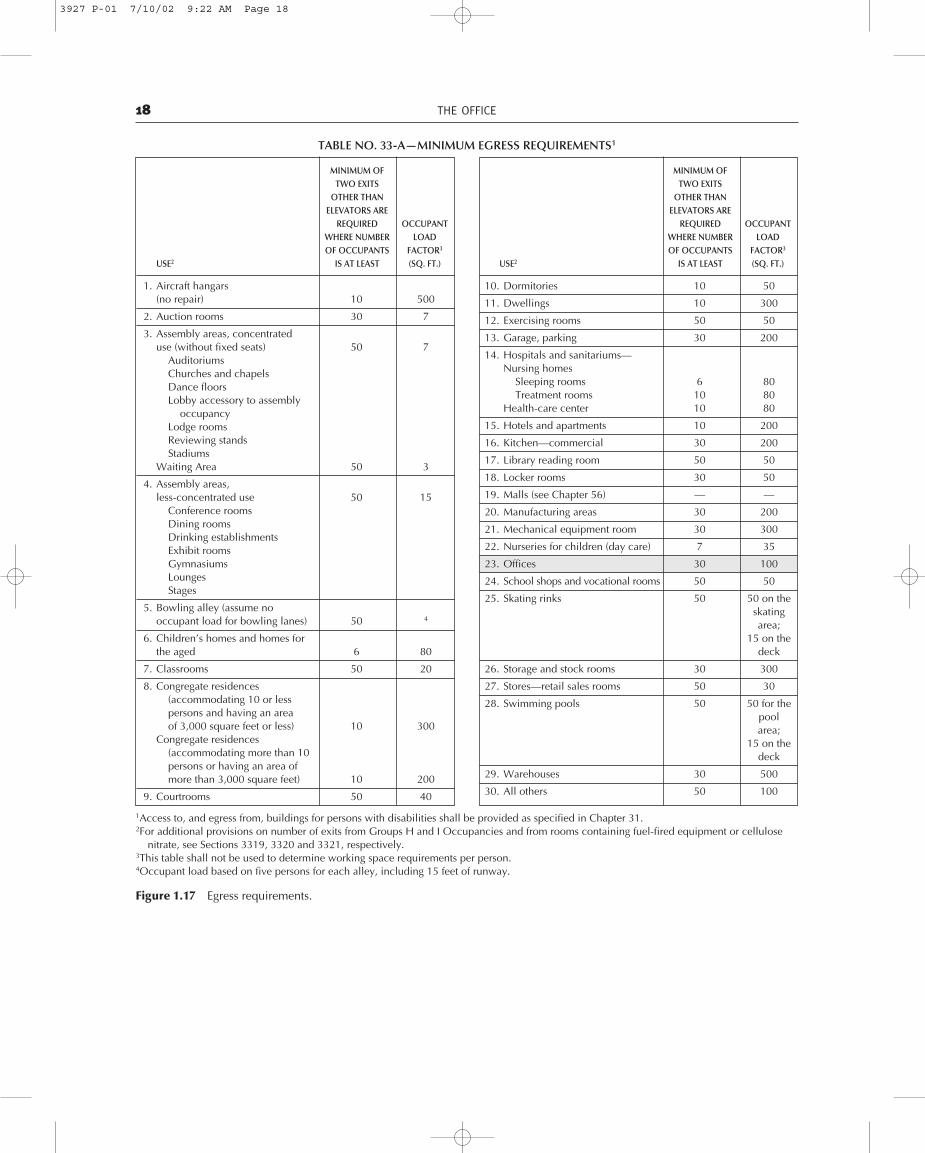
Exit Requirements. Another very important part of abuilding code is the chapter dealing with egress require-ments. This chapter sets forth the number of requiredexits for a specific occupancy use, based on an occupantload factor. The occupant load will depend on the use ofthe building. In the case of a two-story building that isdesigned for office use, the occupant load factor, asillustrated in Figure 1.17, will be 100 square feet. To de-termine the number of exits required, the 100 square-footoccupant load factor is divided into the office floor areaof 10,000 square feet. The resultant occupant factor of100 exceeds the factor of 30, therefore requiring a mini-mum of two exits.
The next step in the design program is to plan the lo-cation of the required exits, required stairs, and anacceptable egress travel. Egress travel is the path to a re-quired exit. The codes will regulate the maximum dis-tance between required exits, the minimum width of exitcorridors, and the entire design of required exit stair-ways. Figure 1.18 depicts the second level floor plan ofthe proposed office building, illustrating an acceptablemethod for the planning of required exits and stair loca-
TABLE NO. 43-B—RATED FIRE-RESISTIVE PERIODS FOR VARIOUS WALLS AND PARTITIONS
Figure 1.14 Fire-resistive wall assemblies (continued).
MINIMUM FINISHED THICKNESS
ITEMFACE-TO-FACE2
MATERIAL NUMBER CONSTRUCTION 4 Hr. 3 Hr. 2 Hr. 1 Hr.
2″ × 4″ wood studs 16″ on center with 7⁄8″ exterior cement plaster (measured17-1.311 16 from the face of studs) on the exterior surface with interior surface treatment Varies
as required for interior wood stud partitions in this table. Plaster mix 1:4 forscratch coat and 1.5 for brown coat, by volume, cement to sand.
35⁄8″ No. 16 gauge noncombustible studs 16″ on center with 7⁄8″ exteriorcement plaster (measured from the face of the studs) on the exterior surface
17-1.4 with interior surface treatment as required for interior, nonbearing, Varies4
17. Exterior noncombustible stud partitions in this table. Plaster mix 1:4 for scratch coator Interior and 1:5 for brown coat, by volume, cement to sand.
Walls 21⁄4″ × 33⁄4″ clay face brick with cored holes over 1⁄2″ gypsum sheathing onexterior surface of 2″ × 4″ wood studs at 16″ on center and two layers 5⁄8″ TypeX gypsum wallboard7 on interior surface. Sheathing placed horizontally orvertically with vertical joints over studs nailed 6″ on center with 13⁄4″ by No.11 gauge by 7⁄16″ head galvanized nails. Inner layer of wallboard placedhorizontally or vertically and nailed 8″ on center with 6d cooler12 or
17-1.516 wallboard12 nails. Outer layer of wallboard placed horizontally or vertically 10and nailed 8″ on center with 8d cooler12 or wallboard12 nails. All jointsstaggered with vertical joints over studs. Outer layer joints taped andfinished with compound. Nailheads covered with joint compound. No. 20gauge corrugated galvanized steel wall ties 3⁄4″ by 65⁄8″ attached to each studwith two 8d cooler12 or wallboard12 nails every sixth course of bricks.
3927 P-01 7/10/02 9:22 AM Page 16

LATESTH1 17
Figure 1.15 Site plan.
Figure 1.16 Graphic building section.
tions. An acceptable egress travel will terminate at thefirst-floor level, exiting outside the structure to a publicright-of-way. A public right-of-way may be a sidewalk,street, alley, or other passage. On the first level floorplan, illustrated in Figure 1.19, the egress travel path ter-minates outside the building through an exit corridor atthe east and west walls of the building.
This particular chapter in the Uniform Building Code,entitled “Exits,” provides a great amount of information
to which the architect or designer will continually referin order to satisfy the many code regulations that will in-fluence the planning and detailing of his or her specificbuilding.
Code Nailing Schedule. In most cases, building coderegulations determine minimum standards for the manyconsiderations associated with the construction of abuilding in order to safeguard public health and welfare.However, this does not mean that the architect or thevarious engineers cannot increase the quality of thesestandards to satisfy their design solutions and opinions.An example of a minimum nailing schedule for Type V(wood) construction is illustrated in Figure 1.20. Forstructures subjected to wind or seismic forces, the engi-neered design may require more nails and a larger sizeof nails in order to satisfy the engineered design criteria.
Standards for Wood. The use of wood is prominent inthe construction of many types of buildings currentlybeing designed. The building codes have an extensivelydeveloped chapter for the various standards required forwood design. This chapter provides an array of tables
3927 P-01 7/10/02 9:22 AM Page 17
18 THE OFFICE
TABLE NO. 33-A—MINIMUM EGRESS REQUIREMENTS1
Figure 1.17 Egress requirements.
MINIMUM OF TWO EXITS
OTHER THANELEVATORS ARE
REQUIRED OCCUPANT WHERE NUMBER LOADOF OCCUPANTS FACTOR3
USE2 IS AT LEAST (SQ. FT.)
1. Aircraft hangars(no repair) 10 500
2. Auction rooms 30 7
3. Assembly areas, concentrated use (without fixed seats) 50 7
AuditoriumsChurches and chapelsDance floorsLobby accessory to assembly
occupancyLodge roomsReviewing standsStadiums
Waiting Area 50 3
4. Assembly areas,less-concentrated use 50 15
Conference roomsDining roomsDrinking establishmentsExhibit roomsGymnasiumsLoungesStages
5. Bowling alley (assume nooccupant load for bowling lanes) 50 4
6. Children’s homes and homes forthe aged 6 80
7. Classrooms 50 20
8. Congregate residences(accommodating 10 or lesspersons and having an areaof 3,000 square feet or less) 10 300
Congregate residences(accommodating more than 10persons or having an area ofmore than 3,000 square feet) 10 200
9. Courtrooms 50 40
MINIMUM OF TWO EXITS
OTHER THANELEVATORS ARE
REQUIRED OCCUPANT WHERE NUMBER LOADOF OCCUPANTS FACTOR3
USE2 IS AT LEAST (SQ. FT.)
10. Dormitories 10 50
11. Dwellings 10 300
12. Exercising rooms 50 50
13. Garage, parking 30 200
14. Hospitals and sanitariums—Nursing homes
Sleeping rooms 6 80Treatment rooms 10 80
Health-care center 10 80
15. Hotels and apartments 10 200
16. Kitchen—commercial 30 200
17. Library reading room 50 50
18. Locker rooms 30 50
19. Malls (see Chapter 56) — —
20. Manufacturing areas 30 200
21. Mechanical equipment room 30 300
22. Nurseries for children (day care) 7 35
23. Offices 30 100
24. School shops and vocational rooms 50 50
25. Skating rinks 50 50 on the skatingarea;
15 on the deck
26. Storage and stock rooms 30 300
27. Stores—retail sales rooms 50 30
28. Swimming pools 50 50 for the poolarea;
15 on thedeck
29. Warehouses 30 500
30. All others 50 100
1Access to, and egress from, buildings for persons with disabilities shall be provided as specified in Chapter 31.2For additional provisions on number of exits from Groups H and I Occupancies and from rooms containing fuel-fired equipment or cellulose
nitrate, see Sections 3319, 3320 and 3321, respectively.3This table shall not be used to determine working space requirements per person.4Occupant load based on five persons for each alley, including 15 feet of runway.
3927 P-01 7/10/02 9:22 AM Page 18

BUILDING 19
Figure 1.19 First level floor plan.
Figure 1.18 Second level floor plan.
dealing with examples, such as allowable unit stressesfor various types of wood species and their grades, thestructural capabilities of plywood relative to its thicknessand properties, the numerous species combinations forglued-laminate timber design and allowable spans forroof rafters, ceiling joists, and floor joists. An example ofone of the many tables to be found in the chapter onwood is given in Figure 1.21. This table includes theallowable spans for various sizes and spacing of floorjoists, based on a specific weight per square foot and ondeflection design criteria.
Bolts in Concrete. For the structural design engineer orarchitect the building codes offer a vast number of work-ing values for wood, concrete, masonry, and structural
steel. These values provide a basis for the selection of thevarious components that are part of many constructionsassemblies found in a specific structure. Figure 1.22illustrates a value table for various sized anchor bolts em-bedded in concrete. These design loads would be themaximum allowable pounds per bolt, with a minimumembedded factor.
Minimum Foundation Requirements
As previously mentioned, many code requirements stip-ulate minimum standards for a specific phase of the con-struction process. An example is the minimum standardsfor foundations for wood stud-bearing walls. Figure 1.23illustrates a table for foundations where there are no
3927 P-01 7/10/02 9:22 AM Page 19

20 ENERGY CODES
TABLE NO. 25-O—NAILING SCHEDULE
CONNECTION NAILING1
1. Joist to sill or girder, toenail 3-8d
2. Bridging to joist, toenail each end 2-8d
3. 1″ × 6″ subfloor or less to each joist, face nail 2-8d
4. Wider than 1″ × 6″ subfloor to each joist, face nail 3-8d
5. 2″ subfloor to joist or girder, blind and face nail 2-16d
6. Sole plate to joist or blocking, face nail 16d at 16″ o.c.
7. Top plate to stud, end nail 2-16d
8. Stud to sole plate 4-8d, toenail or2-16d, end nail
9. Double studs, face nail 16d at 24″ o.c.
10. Doubled top plates, face nail 16d at 16″ o.c.
11. Top plates, laps and intersections, face nail 2-16d
12. Continuous header, two pieces 16d at 16″ o.c.along each edge
13. Ceiling joists to plate, toenail 3-8d
14. Continuous header to stud, toenail 4-8d
15. Ceiling joists, laps over partitions, face nail 3-16d
16. Ceiling joists to parallel rafters, face nail 3-16d
17. Rafter to plate, toenail 3-8d
18. 1″ brace to each stud and plate, face nail 2-8d
19. 1″ × 8″ sheathing or less to each bearing, face nail 2-8d
20. Wider than 1″ × 8″ sheathing to each bearing, face nail 3-8d
21. Built-up corner studs 16d at 24″ o.c.
22. Built-up girder and beams 20d at 32″ o.c. at top and bottom
and staggered2-20d at ends
and at each splice
Figure 1.20 Nailing schedule.
frost conditions or unfavorable soils and geology reportsand no excessive weights acting on the roof and floorsystems.
The student or technician should constantly reviewthe many aspects of the governing building code as it re-lates to the specific region and building techniques.
ENERGY CODES
The Council of American Building Officials has pub-lished a model energy code that is used by the variousbuilding code enforcement agencies throughout thecountry. The purpose of this code is to regulate the de-sign of various types of new building construction, sothat various methods of design can provide high effi-ciency in the use of energy. The basic energy design cri-teria for new construction deals with the building
envelope, which is defined as all the elements of a build-ing encompassing spaces that are conditioned by varioussources of energy. These sources of energy are those thatare required to heat, cool, and provide illumination.
Design Methods
The energy code provides methods and techniques andencourages innovative design systems to achieve aneffective use of energy. There are three methods of de-sign that are accepted as a means of compliance with theintent of the code:
I. A systems approach for the entire building and itsenergy-using subsystems that may use nonde-pletable sources. This method establishes design cri-teria in terms of total energy use by a building,including all of its systems.
II. A component performance approach for the variousbuilding elements and mechanical systems andcomponents. This method provides for buildings thatare heated or mechanically cooled. These are con-structed so as to provide the required thermal per-formance of the various components.
III. Specified acceptable practice. The requirements forthis method are applicable only to buildings of lessthan 5000 square feet in gross floor area and threestories or less in height. This method is also limitedto residential buildings that are heated or mechani-cally cooled and to other buildings that are heatedonly.
Design Influences
If your project falls into the category of Method III, youwill be faced with many design decisions as to the con-struction of the various assemblies within the buildingenvelope, as well as in the selection of mechanical andelectrical equipment. Examples of building assembliesinclude the design and detailing of elements such as theroof, floors, and walls. For these detailed assemblies, itwill be necessary to provide the required amount of in-sulation and to use the method that satisfies the designand energy code criteria.
For the energy design program, it is recommended thatthe architect or designer develop a typical building sec-tion in order to visualize the various building elementsthat will be affected by the energy design requirements.Figure 1.24 illustrates a building section showing ele-ments of the building envelope that will have to be insu-lated. In some cases the size of some of the members ofthe envelope may need to be increased to accommodatethe required depth of insulation, such as the depth ofwood studs and roof joist. Items such as windows andskylights (in Figure 1.24) will be of major concern in the
3927 P-01 7/10/02 9:22 AM Page 20

NOTES:(1)The required extreme fiber stress in bending (Fb) in pounds per square inch is shown below each span.(2)Use single or repetitive member bending stress values (Fb) and modulus of elasticity values (E) from Tables Nos. 25-A-1 and 25-A-2.(3)For more comprehensive tables covering a broader range of bending stress values (Fb) and modulus of elasticity values (E), other spacing of
members and other conditions of loading, see U.B.C. Standard No. 25-21.(4)The spans in these tables are intended for use in covered structures or where moisture content in use does not exceed 19 percent.
TABLE NO. 25-U-J-1—ALLOWABLE SPANS FOR FLOOR JOISTS—40 LBS. PER SQ. FT. LIVE LOAD DESIGN CRITERIA: Deflection—For 40 lbs. per sq. ft. live load. Limited to span in inches divided by 360. Strength—Live load
of 40 lbs. per sq. ft. plus dead load of 10 lbs. per sq. ft. determines the required fiber stress value.
JOISTSIZE SPACING
MODULES OF ELASTICITY, E, IN 1,000,000 PSI
(IN) (IN) 0.8 0.9 1.0 1.1 1.2 1.3 1.4 1.5 1.6 1.7 1.8 1.9 2.0 2.2
8-6 8-10 9-6 9-9 10-0 10-3 10-6 10-9 10-11 11-2 11-4 11-7 11-11
12.0 720 780 830 890 940 990 1040 1090 1140 1190 1220 1280 1320 1410
7-9 8-0 8-4 8-7 8-10 9-1 9-4 9-6 9-9 9-11 10-2 10-4 10-6 10-10
2×6 16.0 790 860 920 980 1040 1090 1150 1200 1250 1310 1360 1410 1460 1550
6-9 7-0 7-3 7-6 7-9 7-11 8-3 8-4 8-6 8-8 8-10 9-0 9-2 9-6
24.0 900 980 1050 1120 1190 1250 1310 1380 1440 1500 1550 1610 1670 1780
11-3 11-8 12-1 12-6 12-10 13-2 13-6 13-10 14-2 14-5 14-8 15-0 15-3 15-9
12.0 720 780 830 890 940 990 1040 1090 1140 1190 1230 1280 1320 1410
10-2 10-7 11-0 11-4 11-8 12-0 12-3 12-7 12-10 13-1 13-4 13-7 13-10 14-3
2×8 16.0 790 850 920 980 1040 1090 1150 1200 1250 1310 1360 1410 1460 1550
8-11 9-3 9-7 9-11 10-2 10-6 10-9 11-0 11-3 11-5 11-8 11-11 12-1 12-6
24.0 900 980 1050 1120 1190 1250 1310 1380 1440 1500 1550 1610 1670 1780
14-4 14-11 15-5 15-11 16-5 16-10 17-3 17-8 18-0 18-5 18-9 19-1 19-5 20-1
12.0 720 780 830 890 940 990 1040 1090 1140 1190 1230 1280 1320 1410
13-0 13-6 14-0 14-6 14-11 15-3 15-8 16-0 16-5 16-9 17-0 17-4 17-8 18-3
2×10 16.0 790 850 920 980 1040 1090 1150 1200 1250 1310 1360 1410 1460 1550
11-4 11-10 12-3 12-8 13-0 13-4 13-8 14-0 14-4 14-7 14-11 15-2 15-5 15-11
24.0 900 980 1050 1120 1190 1250 1310 1380 1440 1500 1550 1610 1670 1780
17-5 18-1 18-9 19-4 11-11 20-6 21-0 21-6 21-11 22-5 22-10 23-3 23-7 24-5
12.0 720 780 830 890 940 990 1040 1090 1140 1190 1230 1280 1320 1410
15-10 16-5 17-0 17-7 18-1 18-7 19-1 19-6 19-11 20-4 20-9 21-1 21-6 22-2
2×12 16.0 790 860 920 980 1040 1090 1150 1200 1250 1310 1360 1410 1460 1550
13-10 14-4 14-11 15-4 15-10 16-3 16-8 17-0 17-5 17-9 18-1 18-5 18-9 19-4
24.0 900 980 1050 1120 1190 1250 1310 1380 1440 1500 1550 1610 1670 1780
Figure 1.21 Floor joist span table.
TABLE NO. 26-H—SHEAR ON ANCHOR BOLTS ANDDOWELS—REINFORCED GYPSUM CONCRETE1
BOLT OR DOWEL SIZE EMBEDMENT SHEAR2
(INCHES) (INCHES) (POUNDS)
3⁄8 Bolt 4 3251⁄2 Bolt 5 4505⁄8 Bolt 5 6503⁄8 Deformed Dowel 6 3251⁄2 Deformed Dowel 6 450
Figure 1.22 Bolt value table.
1The bolts or dowels shall be spaced not closer than 6 inches oncenter.
2The tabulated values may be increased one third for bolts or dowelsresisting wind or seismic forces.
TABLE NO. 29-A—FOUNDATIONS FOR STUD BEARINGWALLS—MINIMUM REQUIREMENTS12
THICK- DEPTHNUMBER OF
THICKNESS OFWIDTH NESS BELOW UN-
FLOORSFOUNDATION WALL
OF OF DISTURBEDSUPPORTED
(Inches)FOOTING FOOTING GROUND
BY THE UNIT (Inches) (Inches) SURFACEFOUNDATION3 CONCRETE MASONRY (Inches)
1 6 6 12 6 12
2 8 8 15 7 18
3 10 10 18 8 24
Figure 1.23 Foundation table.
1Where unusual conditions or frost conditions are found, footings,and foundations shall be as required in Section 2907(a).
2The ground under the floor may be excavated to the elevation of thetop of the footing.
3Foundations may support a roof in addition to the stipulated numberof floors. Foundations supporting roofs only shall be as required forsupporting one floor.
3927 P-01 7/10/02 9:23 AM Page 21

design of the building envelope. The area of glass andtype of glass and the number of skylights will be deter-mined by the energy design computations. These com-putations may indicate that the windows and skylightswill have to be dual-glaze glass rather than single-glazed.
Building Insulation. Insulation requirements for theroof, wall, and floor assemblies will be determined bythe required U factor for that particular element. TheU factor is defined as the time rate of heat flow per unitarea and unit temperature differences between the warmside and cold side air films. The U factor applies to acombination of all the materials that constitute a specificassembly used along the heat-flow path, single materialsused for a building assembly, cavity air spaces, and sur-face air films on both sides of a building assembly. Fig-ure 1.25 depicts an example of an exterior wall assemblywith a combination of various materials that establish aU factor.
Mechanical Equipment. Other influences that will beintegrated into the design problem are items such as me-chanical and electrical equipment. The heating andcooling systems equipment will be sized according to therequired efficiency factor. This factor may be expressedin the maximum allowable Btu (British thermal unit)rating of the equipment, as well as satisfying a prescribedefficiency rating of the equipment. The efficiency ratingof the equipment is established by the equipment man-ufacturer. In Method III, which deals mainly with resi-dential construction, it is required that all heating andcooling equipment be equipped with one thermostat forregulating the space temperature, as well as a readily ac-cessible manual or automatic means to partially restrictor shut off the heating or cooling input to each zone. In
general, various control methods may be implemented toreduce the consumption of energy in heating and cool-ing systems.
Air Leakage in the Building Envelope. For energydesign in the working drawing process, you will be re-quired to provide solutions and details for all exteriorjoints that are sources for air leakage through the build-ing envelope. These exterior joints are such assembliesas windows, doors, wall cavities, spaces between wallsand foundations, spaces between walls and roof-ceilingmembers, and openings for the penetration of variousutility services through the roof, walls, and floors. Allthese openings and any others must be sealed by meansof caulking, gaskets, weatherstripping, or other accept-able methods.
Service Water Heating. Water heating storage tanksand supply piping will have to be installed in accordancewith the energy code. The energy code ordinance will re-quire that specific water heaters be labeled as meetingthe established efficiency requirements, as well as beingequipped with automatic controls for acceptable tem-perature settings and a separate switch for shutdownwhen the use of the system is not required for a specificperiod of time. It should be noted that an analysis of en-ergy expenditure for electrical power distribution andlighting systems is exempt for detached dwellings anddwelling portions of multifamily complexes and is regu-lated by Method III.
The foregoing discussion and illustrations have givena few examples of the influencing factors that will haveto be resolved in the design and working drawing pro-gram. In most cases, because of the complexity of theenergy design process, the energy design calculations,the specifications for equipment, insulation, glass, andconstruction assemblies will be provided by an energyconsultant or mechanical engineer. It is recommendedthat the student or technician obtain a copy of the energycode for reference in conjunction with the building code.
22
Figure 1.24 Envelope insulation. Figure 1.25 Wall assembly combination.
22 ENERGY CODES
3927 P-01 7/10/02 9:23 AM Page 22