productspecification coolmobile c/cr
TRANSCRIPT
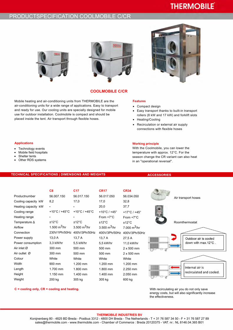
• Technology events• Mobile field hospitals• Shelter tents• Other RDS systems
Features• Compact design• Easy transport thanks to built-in transport
rollers (8 kW and 17 kW) and forklift slots• Heating/Cooling• Recirculation or external air supply
connections with flexible hoses
PRODUCTSPECIFICATION COOLMOBILE C/CR
COOLMOBILE C/CR
THERMOBILE INDUSTRIES BVKonijnenberg 80 - 4825 BD Breda - Postbus 3312 - 4800 DH Breda - The Netherlands - T + 31 76 587 34 50 - F + 31 76 587 27 89
[email protected] - www.thermobile.com - Chamber of Commerce : Breda 20120375 - VAT. nr.: NL 8146.04.365 B01
Working principleWith the Coolmobile, you can lower the temperature with approx. 12°C. For the season change the CR variant can also heat in an "operational reversal".
TECHNICAL SPECIFICATIONS | DIMENSIONS AND WEIGHTS ACCESSORIES
C8
56.007.150 8,2 -
C17
56.017.150 17,0
-
1.200 mm
1.800 mm1.400 mm305 kg
CR17
56.017.050 17,0 20,0
+10°C / +45°From +7°C±12°C3.500 m3/hr400V/3Ph/50Hz13,7 A5,5 kW/hr500 mm500 mmWhite1.200 mm
1.800 mm1.400 mm305 kg
C = cooling only, CR = cooling and heating.
CR34
56.034.050 32,8 37,7
+17°C / +45°From +7°C±12°C7.000 m3/hr400V/3Ph/50Hz27,5 A11,0 kW/hr2 x 500 mm2 x 500 mmWhite1.200 mm
2.250 mm2.050 mm600 kg
Roomthermostat
Air transport hoses
With recirculating air you do not only saveenergy costs, but will also significantly increase the effectiveness.
+10°C / +45°C
-±12°C
1.500 m3/hr
230V/1Ph/50Hz
13,0 A
3,3 kW/hr
300 mm
300 mm
White
900 mm
1.700 mm
1.150 mm
200 kg
+10°C / +45°C
-±12°C
3.500 m3/hr
400V/3Ph/50Hz
13,7 A
5,5 kW/hr
500 mm
500 mm
White
Mobile heating and air-conditioning units from THERMOBILE are the air-conditioning units for a wide range of applications. Easy to transport and ready for use. Our cooling units are specially designed for mobile use for outdoor installation. Coolmobile is compact and should be placed inside the tent. Air transport through flexible hoses.
Applications
Productnumber Cooling capacity kW Heating capacity kW Cooling range Heating rangeTemperature Δ Airflow Connection Power supplyPower consumption Air inlet Ø Air outlet Ø ColourWidth Length Height Weight

1
Thermobile Coolmobile CRMOBILE HEAT PUMP
Cooling only : C8 & C17 Cooling & heating : CR17 & CR34
Features :
Compressors High Efficiency Able to withstand ambient temperature, cooling
from 20°C to 45°C (R410A) Optional EC fan for Cooling from 10°C to 45°C Analogic Pressure Transducer Phase sequence relay protected against re-
versed phases for 3 phase models Room temperature sensor thermostat Low noise level

5
1- PRESENTATION AND OPERATION
This device is a mobile air conditioner for cooling demountable structures such as tents with a cooling capacity from 7 kW to 34 kW, depending of the model. When the relative humidity of the air inlet is high, the air can be cooled below its dew point and humidity is then con-densed to water. This process requires a certain amount of latent cooling but allows a dehumidification process, which is an important factor in comfort for the user.
The operating range is between 20 and 45 ° C and is controlled by the HP / LP pressure. The drop in air temperature depends on the conditions of entry (humidity).
The device are made with two compartment, isolated from each other. Its operation is based on a cooling circuit broken down by two groups motorcycle fans. The side of the device on which connect the ducts contain the evaporator. The fan sucks the warm indoor air, cool this air through the exchanger and return it cold in the tent. The opposite side contain the condenser. The fan draws in ambient outside air, it cross through the exchanger and re-turns it outward.
The cooling system is filled with refrigerant R410a. This circuit is completely waterproof and allows the unit to operate in areas with a maximum ambient temperature of +45 ° C. At high ambient temperatures (above 45 ° C), the cooling of the condenser air flow is too low and a high pressure stops the HP switch. The pressure switches HP / BP will reset automatically after a few minutes.
At an ambient temperature below 20 ° C, moisture in the airflow can form ice on the evaporator. To avoid this, the pres-sure switch cuts the low pressure in the system. If the ambient temperature is too low, the BP activation causes frequent starting and stopping of the compressor. This process can damage the compressor and should be avoided by always using the product within the specified temperature range. See "Specifications".
Exchanger (Condensor)
Exchanger (Evaporator)
Temp. sensor Evaporator
Temp. sensor Condensor
Regulator
Liquid phase
Gas phase
Filter Compressor
To o
utd
oor
To indoor
(Indoor) (Outdoor)
Compressor: Used to circulate the fluid in the cooling circuit Filter: Absorbs moisture and impurities in the cooling circuit Condenser: Sends the heat generated in the tent or room outwards Regulator: Sends the amount of liquid that is right in the evaporator Evaporator: Absorbs heat of the tent or room by cooling the air circulating High pressure switch / BP: To ensure that the compressor does not work at a temperature too low or too high

6
2 GENERAL RULES FOR INSTALLATION
The installation configuration is an important factor in improving the performance and reliability of the air con-ditioner. There are different ways to place the devices, here we give you some important recommendations.
2-1 Ducts
CAUTION: The ducts used are the same diameter as the connections of units. The junction between the diffe-rent lengths must be watertight. The total length of the circuit should not exceed 6 meters per circuit (return and supply). For longer length, please contact us.
Always use the least possible sheath. In general, think that every air duct 3m isolated changes the tempera-ture inside the pipe by 5 ° C.
The sheaths result in a loss that's why we must always put straight, Fig.1. In case of deviation, avoiding signifi-cant bends (bends> 45 °), Fig.2, prefer them large curves, fig.3.
Place the air distribution duct cooled as close to the ceiling, the cold air will descend slowly to the ground and will be returned to the air conditioner through the air duct placed at the lowest, Fig.1.
2-2 Effect of the sun
The heating, due to solar effect reduces the efficiency of the air conditioner, heat builds up in the ducts and in the tents it's greenhouse effect. We recommend installing a sunshade to cover the air conditioning, ducts and the tent. It also becomes more effective if using panels/insulated coatings in the tent.
Fig.1
Fig.3 Fig.2
Fig.1

7
2-3 Airflow
To cool the air effectively, the air sent to the air conditioner must be the lowest possible. If the ambient tempe-rature is lower than outside temperature, it is more efficient to re-circulate the air from the tent. To do this, con-nect the insulated ducts for blowing and sucking of air, between the tent and the air conditioner, fig.4.
If the temperature inside the tent is higher than the outside temperature, it may be advantageous to use the device without air intake duct, fig.5. Attention in this case you risk introducing dust or increase pressure in the tent.
2-4 Various
- Keep doors and openings of the tent/room closed when using the air conditioner.
- Avoid all heat generating sources in the air conditioned room.
- Do not cover, fig.6, or obstruct the rear of the air conditioner, fig.7. Keep a free and clear area for a good aircirculation allowing the correct operation of the conditioner, fig.8 & 9.
- If the air does not circulate well, the unit switches to safety. Poor repeated use causes irreversible damage.
- Always ensure that the exhaust ducts, fig.10, or air intake, fig.11, is not blocked or obstructed even partially.If the air circulation is prevented the unit switches to safety. Poor repeated use causes irreversible damage.
- Accumulation of water produced by condensation, fig.12, disrupt the use of theair conditioner, so we recommend that you raise the unit on a pallet for example,or to evacuate the condensate to a remote area of the air conditioner.
Fig.4 Fig.5
Fig.6 Fig.7
OIL OIL
Fig.8
1 m
1 m
2 m
2 m
1 m
Fig.9
Fig.10 Fig.11
Fig.12

8
CARACTÉRISTIQUES TECHNIQUES / TECHNICAL SPECIFICATIONS
* The cooling capacity can change considerably depending on the humidity and air termperature.** Optional EC Axial fan for cooling from 10°C instead of 20°C ambient temperature.
Nominal ton 2,2 4,8 4,8 9,5
Model C8 C17 CR17 CR34
Capacity Cooling mode* Cooling Capacity Btu/h 28 000 58 000 58 000 111 000
W 8 200 17 000 17 000 32 800
Capacity Heating mode* Heating Capacity Btu/h - - 58 000 111 000
W - - 20 000 32 800
Electrical data
Power supply V-PH-Hz 230-1-50 380-3-50 380-3-50 380-3-50
Rated power Input W 3 300 5 500 5 500 13 000
Performance
Air Circulation (High
speed) m3/h 1 500 4 500 4 500 7000
Indoor external static
pressure Pa 100 100 100 100
Indoor Coil
Number of rows 3 3 3 3
Fin spacing mm 2,3 2,3 2,3 2
inch 3/32 3/32 3/32 3/32
Special
Grooved Tube Grooved Tube Grooved Tube Grooved Tube
Louvered fins Louvered fins Louvered fins Louvered fins
hydrophilic aluminum fins hydrophilic aluminum fins hydrophilic aluminum fins hydrophilic aluminum fins
Tube diameter mm Ф9.54 Ф9.54 Ф9.54 Ф9.54
inch 3/8 3/8 3/8 3/8
Indoor fan
Type Centrifugal Blower Centrifugal Blower Centrifugal Blower Centrifugal Blower
No. used 1 1 1 2
Diameter mm Ф280mm Ф355mm Ф355mm Ф355mm
inch 11 14 14 14
Drive type DIRECT DIRECT DIRECT DIRECT
No. motors 1 1 1 2
Motor output W 240 315 315 315
Motor rpm r/min 2600 1780 1780 1 780
Compressor
Type Rotary Scroll Scroll Scroll
Quantity 1 1 1 1
Model PA331X3CS C-SBP205H38 C-SBP205H38 C-SCP400H38
- - - -
Brand GMCC PANASONIC PANASONIC PANASONIC
Capacity Btu/hr 28 000 58 000 58 000 111 000
Input W 3 300 5 500 5 500 11 000
Rated current(RLA) A 13 10,3 10,3 20
Refrigerant oil charge TYPE - mL ESTER OIL VG74 · 1100 FV 68S - 1600 FV 68S - 1600 ‘
Outdoor Coil
Number of rows 2 2 2 2
Fin spacing mm 1,8 1,8 1,8 2
inch 0,0709 0,0709 0,0709 0,0709
Special
Grooved Tube Grooved Tube Grooved Tube Grooved Tube
Louvered fins Louvered fins Louvered fins Louvered fins
hydrophilic aluminum fins hydrophilic aluminum fins hydrophilic aluminum fins hydrophilic aluminum fins
Tube diameter mm Ф9.54 Ф9.54 Ф9.54
inch 3/8 3/8 3/8 3/8
Outdoor Fan
Type Axial Axial Axial Axial
No. used 1 1 1 1
Diameter mm Ф450 Ф630 Ф630 Ф800
inch 17,8 24,8 24,8 32
Drive type Direct Direct Direct Direct
No. motors 1 1 1 1
Motor model ATE804S ATE808S ATE808S ATE810AP
Motor output W 420 520 520 1 250
Motor rpm r/min 1350 900 900 700
Refrigerant
Type R410A R410A R410A R410A
Refrigerant volume kg 2,1 3,6 3,6 7,2
Refrigerant Control EEVX EEVX EEVX EEVX
Dimensions(W×H×D) mm 900x1150x1700 1200x1400x1800 1200x1400x1800 1200x2050x2250
inch 35x45x67 47x55x71 47x55x71 47x81x88
Net Weight kg 200 305 305 600
Ibs 386 672 672 1 322

9
Dimensions C8
Dimensions C17 & CR17

10
Dimensions CR34

19
COMPONENTS:
LIST OF COMPONENTS
Item
1 OUTDOOR HEAT EXCHANGER
2 TOUCHPAD PCB
3 PCB
4 SAFETY SWITCH
5 CONTACTOR
6 THERMOSTAT IN
7 FOUR WAY VALVE
8 OUTDOOR AXIAL FAN
9 LOW PRESSURE TRANSDUCER
10 SUCTION SIDE TEMPERATURE SENSOR
11 HIGH PRESSURE TRANSDUCER
12 SCHRADRE VALVE HIGH SIDE
13 OUTDOOR HEAT EXCHANGER TEMPERATURE SENSOR
14 FILTER
15 OUT COMPRESSOR TEMPERATURE SENSOR
16 COMPRESSOR
17 SCHRADRE VALVE LOW SIDE
18 INDOOR HEAT EXCHANGER TEMPERATURE SENSOR
19 ELECTRONIC EXPANSION VALVE
20 INDOOR HEAT EXCHANGER
21 INDOOR CENTRIFUGAL FAN