products and innovations spring 2009 / brochures / 2009-04 · products and innovations spring 2009...
TRANSCRIPT

Products and Innovations
Spring 2009
Drive Technology \ Drive Automation \ System Integration \ ServicesSEW-EURODRIVE—Driving the world
For every motion in your machines and systems and for every industry: As a leading drive technology specialist, we always supply the right drive. This includes not only gear units, motors or drive electronics, but also the matching controller and a comprehensive service portfolio. This is what we call Drive 360° – Seeing the big picture: From system availability to problem-solving competence, from low operating costs over energy efficiency to the complete system that handles all your tasks.
www.sew-eurodrive.com
Seeing the big picture.
Seeing the big picture.
Seeing the big picture.
Seeing the big picture.
Seeing the big picture.
Seeing the big picture.
Seeing the big picture.
Seeing the big picture.
From the first idea to the running system, and beyond.
1677
001
3 /
0409

DriveGate – The customer service portal
DriveGate offers customers of SEW-EURODRIVE a wide range of services. It is the central
online platform of SEW-EURODRIVE that provides numerous options for improving and
optimizing internal processes, including expert consultation, in a convenient and clearly
structured manner.
The SEW Workbench is a planning and configu-ration tool to specify SEW-EURODRIVE products. Simple and clearly arranged graphical elements let you create complex configurations and verify their proper functioning. A great number of new functions offer additional options for creating exactly the drive solution required for the specific
application. The SEW Workbench includes a complete electronic product catalog, all required documentation, and an option for creating individual CAD files. The SEW Workbench DVD provides customers of SEW-EURODRIVE with a personal code for easy registration to the Drive-Gate customer portal.
The “Drive Engineering – Practical Implementa-tion” series of publications as well as various documentations (docu ROMs) and presentations (CBI-ROM) on CD-ROM are the ideal tools of reference for any question on drive technology.
They also include detailed basic information, explanations, and useful tips. All this is arranged in a clear structure and with the focus on practi-cal applications.
The advantages at a glance
– Registration and login free of charge– User-friendly user interface– Clear design
– Fast and direct access– Many convenient download functions– Available 24 hours a day, worldwide
SEW Workbench
Useful reference tools
[email protected] SEW-EURODRIVE’s DriveGate offers uncomplicated access, for example, to
5
Contents 2
Products and Innovations Spring 2009
SEW-Eurodrive—Driving the world
Not all the products listed here are available worldwide. If you have anyquestions on the terms and conditions for delivery, please contact yourSEW-EURODRIVE country representative.
XXL production for XXL industrial gear units 4Seeing the big picture: Product-independent, industry-specific solutions, worldwide 8CLASSIC drive technology: Variety and quality from the modular system 10VARIOLUTION® packages for all industries 12MAXOLUTION® system solutions for individual requirements 14effiDRIVE® Energy-saving concepts 16Our contribution to reduce Total Cost of Ownership 18
Drive Benifts 138CDS® – Complete Drive Service 140
Knowledge transfer:DriveAcademy® 142DriveGate 143
Product announcement: Stainless steel gear units 20Product announcement: MOVIDRIVE® up to 315 kW 22Product announcement: CMP servomotor series, sizes 71-100 24Product announcement: Servo drive technology for potentially explosive atmospheres 26
Seeing the big picture
Services
Innovations Spring 2009
143

7
– State-of-the-art production technology
– Precise production processes
– Enormous capacities
– Unique expertise
– Perfect location solution
– Fastest logistics
XXL in all areas
The new XXL production for XXL industrial gear units gives SEW-EURODRIVE an
enormous competitive edge and makes it well equipped for the challenges of the future.
8 SEW-EURODRIVE
Seeing the big picture
Drive technology from SEW-EURODRIVE stands for product variety and quality, reliability and
innovative strength. Features that all our products of the comprehensive modular system,
the CLASSIC drive technology, have in common and have made SEW-EURODRIVE one
of the leading manufacturers of drive technology worldwide.
CLASSIC – a perfect basis also for all the challenges of the future. In order to “see the big picture” and to implement all the solutions, SEW-EURODRIVE has been continuously developing its range of products and services: For example with the new, industry-oriented VARIOLUTION® packages and MAXOLUTION® system solutions to meet the specific applications required by the
customer. Or with the range of services to sup-port our customers, for example with internal process optimizations.
SEW-EURODRIVE is undergoing a change – the change to a drive technology expert: We create and implement solutions today for the tasks of tomorrow – worldwide.
This is what we call Drive 360° – Seeing the big picture: We see our expertise and problem solving competence, our drive technology and services as part of a whole: Your solution for highest machine and system availability, low operating costs, and optimum energy efficiency.
3
Standard gear units / standard gearmotors 30Accessories and options 34Overhead trolley drives 36Explosion-proof drives 38Aseptic gearmotors 42Corrosion and surface protection 44DRS/DRE/DRP series standard and energy efficient motors 48Modular brake system, built-in encoders and additional features 51
DRL/DRM/DRK series AC motors 54MOVITRAC® B frequency inverters 56MOVIDRIVE® inverters 58Options MOVITRAC® B and MOVIDRIVE® 60MOVITRAC® LTE B frequency inverters 62effiDRIVE® Energy efficiency of frequency and drive inverters 64MOVIGEAR® – The mechatronic drive system 66
MOVIAXIS® multi-axis servo drives 72effiDRIVE® Energy efficiency with servo drive systems 74Synchronous servomotors 76Cable management and connection options 78Synchronous linear servomotors 80
Electric cylinders 82Planetary servo gear units 84Helical-bevel servo gear units 86System solutions with servo gearmotors 88
MOVIMOT®, gearmotor with integratedfrequency inverter 94MOVI-SWITCH®, gearmotor with integratedswitching and protection function 95Fieldbus interfaces, field distributors and cable systems 96
MOVIFIT®, decentralized drive controller 98 MOVIPRO® decentralized drive and position controller 102MOVITRANS®, contactless energy transfer 104
Helical gear units / Bevel-helical gear units 110Planetary gear units 111Explosion-proof industrial gear units 112
MOVI-PLC® controller 116MOVI-PLC® I/O system and remote maintenance 120MOVI-PLC® programming and parameterization 121 Functional safety technology 122Safety fieldbus PROFIsafe 124Diagnostic units 126Operator terminals 128Startup software MOVITOOLS® MotionStudio 130
Configurable system software MOVIVISION® 132Project planning tools:– Servo project planning tool 134– EPLAN® macros / Sample programs for SIMATIC S7 135Fieldbus concepts Industrial Ethernet and EtherCAT 136
12
34
5
Gearmotos and frequency inverters 28
Servo drive systems 70
Decentralized drive systems 92
Industrial gear units 108
Other system components and services 115
CL
AS
SIC

4 SEW-EURODRIVE 6
Incredible production powerXXL production for XXL industrial gear units

4 SEW-EURODRIVE 6
Incredible production powerXXL production for XXL industrial gear units

4 SEW-EURODRIVE 6
Incredible production powerXXL production for XXL industrial gear units

7
– State-of-the-art production technology
– Precise production processes
– Enormous capacities
– Unique expertise
– Perfect location solution
– Fastest logistics
XXL in all areas
The new XXL production for XXL industrial gear units gives SEW-EURODRIVE an
enormous competitive edge and makes it well equipped for the challenges of the future.
8 SEW-EURODRIVE
Seeing the big picture
Drive technology from SEW-EURODRIVE stands for product variety and quality, reliability and
innovative strength. Features that all our products of the comprehensive modular system,
the CLASSIC drive technology, have in common and have made SEW-EURODRIVE one
of the leading manufacturers of drive technology worldwide.
CLASSIC – a perfect basis also for all the challenges of the future. In order to “see the big picture” and to implement all the solutions, SEW-EURODRIVE has been continuously developing its range of products and services: For example with the new, industry-oriented VARIOLUTION® packages and MAXOLUTION® system solutions to meet the specific applications required by the
customer. Or with the range of services to sup-port our customers, for example with internal process optimizations.
SEW-EURODRIVE is undergoing a change – the change to a drive technology expert: We create and implement solutions today for the tasks of tomorrow – worldwide.
This is what we call Drive 360° – Seeing the big picture: We see our expertise and problem solving competence, our drive technology and services as part of a whole: Your solution for highest machine and system availability, low operating costs, and optimum energy efficiency.
3
Standard gear units / standard gearmotors 30Accessories and options 34Overhead trolley drives 36Explosion-proof drives 38Aseptic gearmotors 42Corrosion and surface protection 44DRS/DRE/DRP series standard and energy efficient motors 48Modular brake system, built-in encoders and additional features 51
DRL/DRM/DRK series AC motors 54MOVITRAC® B frequency inverters 56MOVIDRIVE® inverters 58Options MOVITRAC® B and MOVIDRIVE® 60MOVITRAC® LTE B frequency inverters 62effiDRIVE® Energy efficiency of frequency and drive inverters 64MOVIGEAR® – The mechatronic drive system 66
MOVIAXIS® multi-axis servo drives 72effiDRIVE® Energy efficiency with servo drive systems 74Synchronous servomotors 76Cable management and connection options 78Synchronous linear servomotors 80
Electric cylinders 82Planetary servo gear units 84Helical-bevel servo gear units 86System solutions with servo gearmotors 88
MOVIMOT®, gearmotor with integratedfrequency inverter 94MOVI-SWITCH®, gearmotor with integratedswitching and protection function 95Fieldbus interfaces, field distributors and cable systems 96
MOVIFIT®, decentralized drive controller 98 MOVIPRO® decentralized drive and position controller 102MOVITRANS®, contactless energy transfer 104
Helical gear units / Bevel-helical gear units 110Planetary gear units 111Explosion-proof industrial gear units 112
MOVI-PLC® controller 116MOVI-PLC® I/O system and remote maintenance 120MOVI-PLC® programming and parameterization 121 Functional safety technology 122Safety fieldbus PROFIsafe 124Diagnostic units 126Operator terminals 128Startup software MOVITOOLS® MotionStudio 130
Configurable system software MOVIVISION® 132Project planning tools:– Servo project planning tool 134– EPLAN® macros / Sample programs for SIMATIC S7 135Fieldbus concepts Industrial Ethernet and EtherCAT 136
12
34
5
Gearmotos and frequency inverters 28
Servo drive systems 70
Decentralized drive systems 92
Industrial gear units 108
Other system components and services 115
CL
AS
SIC

8 SEW-EURODRIVE
Seeing the big picture
Drive technology from SEW-EURODRIVE stands for product variety and quality, reliability and
innovative strength. Features that all our products of the comprehensive modular system,
the CLASSIC drive technology, have in common and have made SEW-EURODRIVE one
of the leading manufacturers of drive technology worldwide.
CLASSIC – a perfect basis also for all the challenges of the future. In order to “see the big picture” and to implement all the solutions, SEW-EURODRIVE has been continuously developing its range of products and services: For example with the new, industry-oriented VARIOLUTION® packages and MAXOLUTION® system solutions to meet the specific applications required by the
customer. Or with the range of services to sup-port our customers, for example with internal process optimizations.
SEW-EURODRIVE is undergoing a change – the change to a drive technology expert: We create and implement solutions today for the tasks of tomorrow – worldwide.
This is what we call Drive 360° – Seeing the big picture: We see our expertise and problem solving competence, our drive technology and services as part of a whole: Your solution for highest machine and system availability, low operating costs, and optimum energy efficiency.

9
Focus on the details: Product-independent and
industry-specific solutions – worldwide
Ensure smooth and reliable plant operation, minimize the maintenance effort, and maximize the added value for our customers – these are the objectives of SEW-EURODRIVE when talk-ing about industry-specific solutions. We want to make sure that you operate your machines and systems in a safe and efficient manner at any time so that unproductive downtimes can be avoided.
Products and systems from SEW-EURODRIVE are therefore used all over the world: In indus-tries such as automotive, building and building materials, food and consumer goods, metal pro-cessing or wood processing, transportation and logistics, in ports or airports, and many more. The decision to use drive technology “made by SEW-EURODRIVE” means reliability for function and investment.
SEW-EURODRIVE supports and ensures all this by its global presence: Twelve production plants and 66 assembly plants in 46 countries provide for worldwide availability, short delivery times,
and comprehensive service, which we view as integrative service concept we consistently im-plement in customer orientation.
All these components together in their entirety make SEW-EURODRIVE one of the top drive technology suppliers worldwide. And even more, they make SEW-EURODRIVE a global partner that solves problems and provides an answer to any challenge. Seeing the big picture: go to www.drive360.de for more details

10 CLASSIC drive technology
CLASSIC: Variety and quality from the modular system
CLASSIC drive components from SEW-EURODRIVE have become firmly established in the in-
ternational machine and plant engineering industry. The SEW-EURODRIVE modular concept
offers millions of combinations and, as a result, provides the perfect condition for choosing
the drive that optimally suits the specific application.
No matter whether the components are me-chanical, electronic, or mechatronic ones, they are used depending on the speed and torque range, space, and ambient conditions required by the specific application. CLASSIC drive tech-
nology from SEW-EURODRIVE implements an infinite number of customized drive solutions matching the specific requirement profiles.

11
Gearmotors and frequency invertersOur gear units and gearmotors offer an un-matched fine graduation of power ranges and excellent economical requirements for use in many machines and systems. Our electronic components, the MOVITRAC® frequency invert-ers and MOVIDRIVE® drive inverters, supple-ment our gearmotors and blend perfectly with
the systems offered by SEW-EURODRIVE. As in the case for mechanical systems, the develop-ment, production and assembly is also carried out completely by SEW-EURODRIVE. In combi-nation with our drive electronics, these drives provide the utmost in flexibility.
Servo drive systemsProducts of the servo drive system from SEW-EURODRIVE convince by their precision and dynamics. Low-backlash servo gear units, compact servomotors, electric cylinders, and MOVIAXIS® multi-axis servo inverters provide
exact movements for any system architecture. From single-axis or multi-axis applications all the way to synchronized process sequences, servo drive systems from SEW-EURODRIVE offer flexible and customized solutions.
Industrial gear unitsPower, quality, and sturdy design combined in one standard product: Industrial gear units from SEW-EURODRIVE combine all requirements of modern industrial gear units. Standardized but always flexible due to the modular concept,
industrial gear units from SEW-EURODRIVE can even be operated under difficult conditions and provide movement wherever high torque ratings and maximum reliability are required.
Decentralized drive technologySEW-EURODRIVE provides control cabinet inde-pendent components from its decentralized drive system for economical, decentralized installation. For example, MOVIFIT®, the decentralized drive controller, MOVIMOT®, the gearmotor with inte-grated frequency inverter, or MOVI-SWITCH®, the gearmotor with integrated switching and protec-tion function. And with the hybrid cables specifi-
cally designed by SEW-EURODRIVE, we ensure cost-effective solutions, independent of system philosophy or size.
Latest developments of SEW-EURODRIVE: MOVITRANS®, system components for contactless energy transfer, and MOVIPRO®, the decentralized drive and positioning controller.

12
VARIOLUTION® packages
With the experience of a leading manufacturer of drive technology,
SEW-EURODRIVE continuously develops new drive concepts for future challenges in
mechanical and plant engineering. We place special emphasis on the fast and simple
integration of these solutions into existing process chains of system manufacturers and
end customers.
VARIOLUTION® – Functionality for all industries
Our VARIOLUTION® packages
Automotive − Electrified monorail system for light loads
− Electrified monorail system for heavy loads
− Automated guided vehicle system
− Skillet conveyor system− Skid conveyor technology− Welding tongs− Scissor lift table
Food + Beverage − Item transport− Packaging unit transport− Packer and unpacker− FFS machine− Flighted chain
Transport + Logistics − Stationary vertical conveyor− Roller conveyer− Corner transfer unit− Storage and retrieval system− High-level palletizer

13
The VARIOLUTION® packages are the latest result of our development:− Proven drive and automation technology− Function-oriented software modules− Optimized order and delivery processes − Application-specific documentation
We have succeeded in creating the optimal combination of industry standardy and industry-specific requirements, of our application exper-tise and concepts for faster processes and pro-duction reliability. VARIOLUTION® packages are
scalable drive solutions which incorporate our expertise and competence and ensure fast and economical solutions in mechanical and plant engineering applications:
Added value for industry-specific drive solutions:− Scalable modularity− High variability− Planning safety− Easy cost reduction
The optional and package-specific services of VARIOLUTION® packages make for reduced effort and cost savings.
Components of the VARIOLUTION® packages
Standard − Drives − Frequency inverters− Controller− Software module− Cables
− Sensor technology− Project planning − Documentation− Warranty of proper function
Optional − Service− Customization– Logistics options– Safety technology
Package specific − Energy efficiency− Operator terminals− Visualization software− Hygienic design− Communication
− Contactless energy transfer

14
MAXOLUTION® system solutions
MAXOLUTION® Individual system solutions for every movement
MAXOLUTION® systems provide future-oriented, new standards: Individual system solutions by
SEW-EURODRIVE with guarantee for success. MAXOLUTION® systems offer all the compo-
nents needed to implement customer-specific solutions for systems and machines. These
components range from electromechanical drives and the controller to communication and
visualization to contactless energy transfer.
System specialists with industry-specific expertise make up a core team that cooper-ates closely with the sales and service staff you know. In this way we guarantee optimum
support and technical advice from project planning to maintenance — competent, fast, straightforward and comprehensive.
From planning to maintenance –
everything from one source:
Individual system solutions
System expertise,
consulting
competence
concept pre-
paration, project
planning
technology
modules
project
management and
processing
startup, accept-
ance, production
monitoring
system
documentation
training,
maintenance

15
Based on our CLASSIC components and the VARIOLUTION® packages, such as AGV or EMS, we offer individual, customized solutions for systems and machines in all areas of system automation. The resulting standardization and optimum matching of all components make for fewer interfaces and less maintenance storage.
As a consequence, the costs incurred through-out the entire product life cycle decrease sig-nificantly. At the same time, the performance and flexibility of your machines is improved and power consumption is reduced.
16 effiDRIVE®
Energy-saving concepts
Dwindling resources and rising energy costs prompt all companies worldwide to analyze
and evaluate the energy efficiency of their systems as well as the amount of follow-up
costs involved.
The answer of SEW-EURODRIVE to this requirement is effiDRIVE®: Energy-saving concepts
which implement the best possible energy-efficient solution for the specific application.
1. Modular energy-saving system
effiDRIVE® energy-saving concepts use the components of the modular energy-saving system. Each of these components has great
energy-saving potential. Their meaningful combination will achieve best possible energy efficiency.
2. Energy consulting
effiDRIVE® energy-saving concepts include energy consulting that includes a comprehensive
review and the consequent implementation of all relevant energy-saving factors.
3. Energy-efficient solutions
effiDRIVE® energy-saving concepts implement the most energy-efficient solution in every in-
dustry, machine, and system and will result in permanently low energy expenses.

17
Modular energy-saving
system
Energy consulting
Energy-efficient solutions
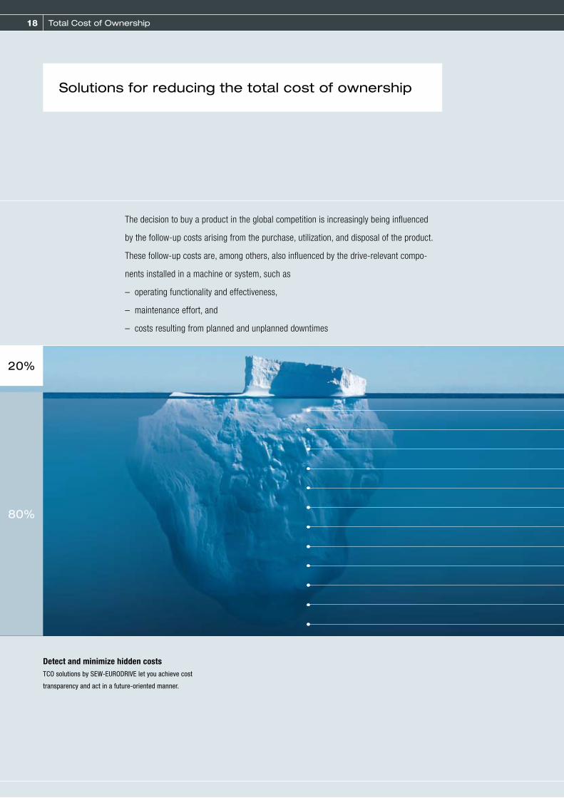
18 Total Cost of Ownership
The decision to buy a product in the global competition is increasingly being influenced
by the follow-up costs arising from the purchase, utilization, and disposal of the product.
These follow-up costs are, among others, also influenced by the drive-relevant compo-
nents installed in a machine or system, such as
– operating functionality and effectiveness,
– maintenance effort, and
– costs resulting from planned and unplanned downtimes
Solutions for reducing the total cost of ownership
80%
20%
Detect and minimize hidden costsTCO solutions by SEW-EURODRIVE let you achieve cost
transparency and act in a future-oriented manner.

19
To
tal
Co
st
of
Ow
ne
rsh
ip (
TC
O)
Startup
Training
Additional accessories
Spare parts
Maintenance/service
Personnel
Tax
Insurance
Energy
Replacement system procurement
Retrofitting
Disposal
Investment costs
TCO solution by SEW-EURODRIVE increase the efficiency of your processes and make a sustainable contribution to the reduction of CO2 emissions.
Reducing energy costsMore than 95 % of a motor‘s life cycle costs are energy costs. The highly efficient energy-saving motors from SEW-EURODRIVE are equipped with copper die-cast rotors. These rotors have a high electric conductance and minimized heat and additional losses resulting in great energy-saving potential when it comes to energy consumption.
Reducing maintenance effortFor example with MOVITRANS® contactless energy transfer. This technology is based on the principle of induction allowing for con-tactless energy transfer. Its application is simple and robust, and it is free of wear and soiling. Result: longer maintenance intervals and higher system availability.
Reducing overall costsThe MOVIGEAR® mechatronic drive system combines motor, gear unit and electronics in a compact housing with the result that energy is reduced by up to 50 %. Installation, startup, and integration can be carried out quickly thanks to the networking capability of the components. Result: reduction of overall costs.
costs
Reducing follow-up costs:

20
Product announcements
NEW: Stainless steel gear units for use in areas subject to frequent cleaning
Stainless steel gearmotors from SEW-EURODRIVE keep things moving wherever machines and
systems are subject to particularly intensive cleaning. Regardless of whether the gear units are
used for materials handling, intralogistics or hygienic applications, their hygienic properties,
long operating life and maintenance friendliness make them optimally suited to the specific
production conditions in the food and beverage industry, pharmaceutical industry, and in
permanently wet environments.
21
The efficiency optimized KESA37 helical-bevel gear units are characterized by their special housing design and the use of high-quality stainless steel: their surface is easy to clean and highly resistant against acids and alkalis. Re-cesses where dirt and liquid might accumulate
were eliminated as far as possible. All seals and connections are available up to degree of pro-tection IP69K. The complete stainless steel ver-sion prevents any corrosion efficiently.
Technical data
Type Max. output torque [Nm] Gear unit reduction ratio [i]
KESA37 200 3.98 … 106.38
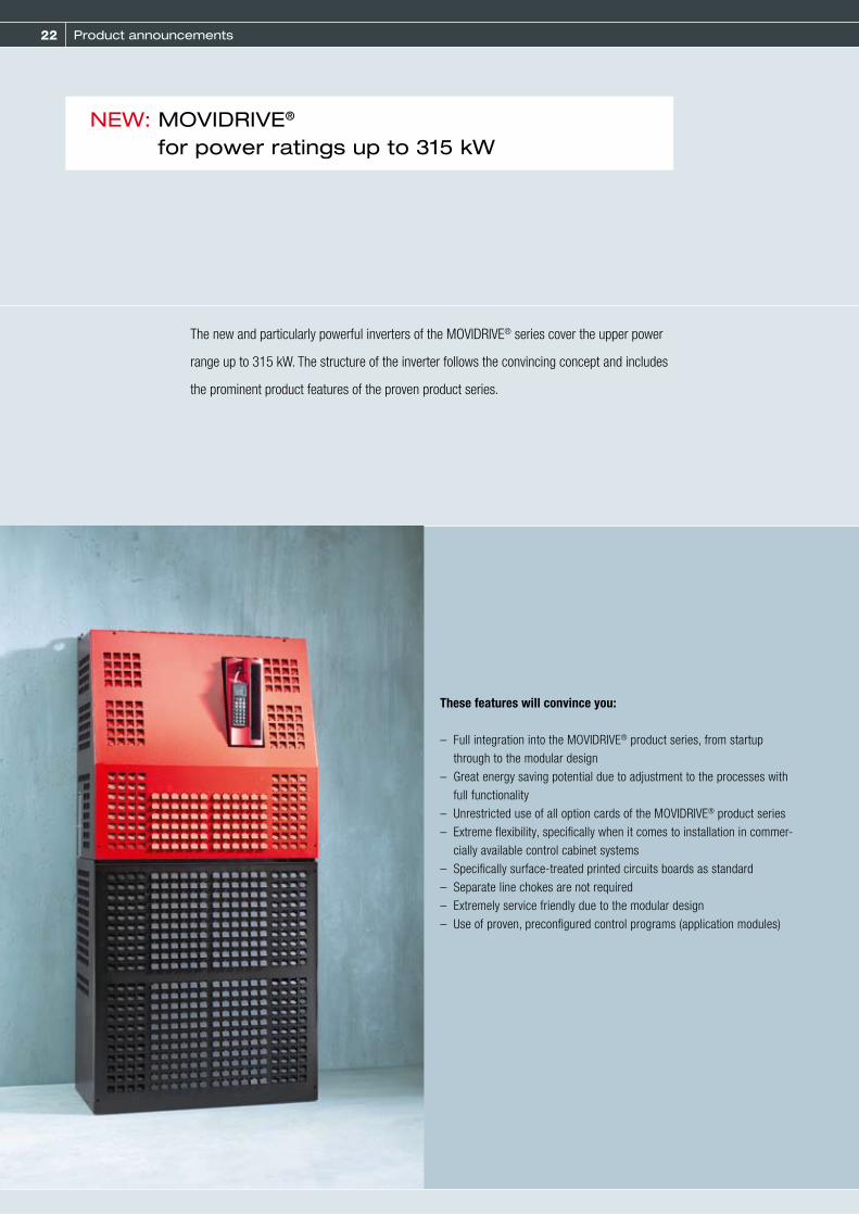
22
Product announcements
NEW: MOVIDRIVE® for power ratings up to 315 kW
The new and particularly powerful inverters of the MOVIDRIVE® series cover the upper power
range up to 315 kW. The structure of the inverter follows the convincing concept and includes
the prominent product features of the proven product series.
These features will convince you:
– Full integration into the MOVIDRIVE® product series, from startup through to the modular design
– Great energy saving potential due to adjustment to the processes with full functionality
– Unrestricted use of all option cards of the MOVIDRIVE® product series– Extreme flexibility, specifically when it comes to installation in commer-
cially available control cabinet systems– Specifically surface-treated printed circuits boards as standard– Separate line chokes are not required– Extremely service friendly due to the modular design– Use of proven, preconfigured control programs (application modules)
23
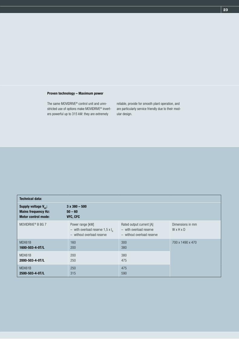
Proven technology – Maximum power
The same MOVIDRIVE® control unit and unre-stricted use of options make MOVIDRIVE® invert-ers powerful up to 315 kW: they are extremely
reliable, provide for smooth plant operation, and are particularly service friendly due to their mod-ular design.
Technical data:
Supply voltage VAC: 3 x 380 – 500Mains frequency Hz: 50 – 60Motor control mode: VFC, CFC
MOVIDRIVE® B BG 7 Power range [kW] – with overload reserve 1,5 x IN– without overload reserve
Rated output current [A] – with overload reserve – without overload reserve
Dimensions in mm W x H x D
MDX61B1600-503-4-0T/L
160200
300380
700 x 1490 x 470
MDX61B2000-503-4-0T/L
200250
380475
MDX61B2500-503-4-0T/L
250315
475590

24 Product announcements
Labeling or sealing applications in the food and beverage industry with 1,200 cycles or
stacking heavy loads weighing 1,200 kg in the construction, automotive or timber industry –
almost always, there is a CMP servomotor from SEW-EURODRIVE behind it.
The newly developed sizes 71, 80 and 100 now also open up the range up to 179 Nm peak
torque. They combine all advantages of the known CMP servomotors with those of the
proven DS/CM motors.
NEW: CMP synchronous servomotor series extended by sizes 71 – 100

25
Technical data
Type Speed category [1/min] M0 [Nm] MpK [Nm] CMP Jmot [kgcm²] CMPZ Jmot [kgcm²]
CMP71S / CMPZ71S 3000 / 4500 /6000 6.4 19.2 3.04 11.02
CMP71M / CMPZ71M 3000 / 4500 / 6000 9.4 30.8 4.08 12.07
CMP71L / CMPZ71L 3000 / 4500 / 6000 13.1 46.9 6.18 14.17
CMP80S / CMPZ80S 3000 / 4500 / 6000 13.4 42.1 8.78 30.88
CMP80M / CMPZ80M 3000 / 4500 / 6000 18.7 62.6 11.9 34
CMP80L / CMPZ80L 3000 / 4500 / 6000 27.5 107 18.1 40.21
CMP100S / CMPZ100S 3000 / 4500 25.5 68.3 19.59 84.99
CMP100M / CMPZ100M 3000 / 4500 31 108 26.49 91.9
CMP100L / CMPZ100L 3000 / 4500 47 178.8 40.24 105.65
Overview of benefits– Quick and reliable project planning for all
system components with SEW Workbench– Motor mounted to the gear unit and
prefabricated cables for quick installation– Electronic nameplate for quick and simple
startup– Low-inertia rotor of the CMP minimizes the
percentage of energy required for motor acceleration
– Powerful rotor of the CMPZ controls even extreme loads stiffly, safely and accurately
– Finely scaled and stepped motor range with 17 levels
– Powerful spring-loaded brake with working capacity suitable for hoist axes
– Can be used worldwide thanks to and– Quick support by global assembly centers
26 Product announcements
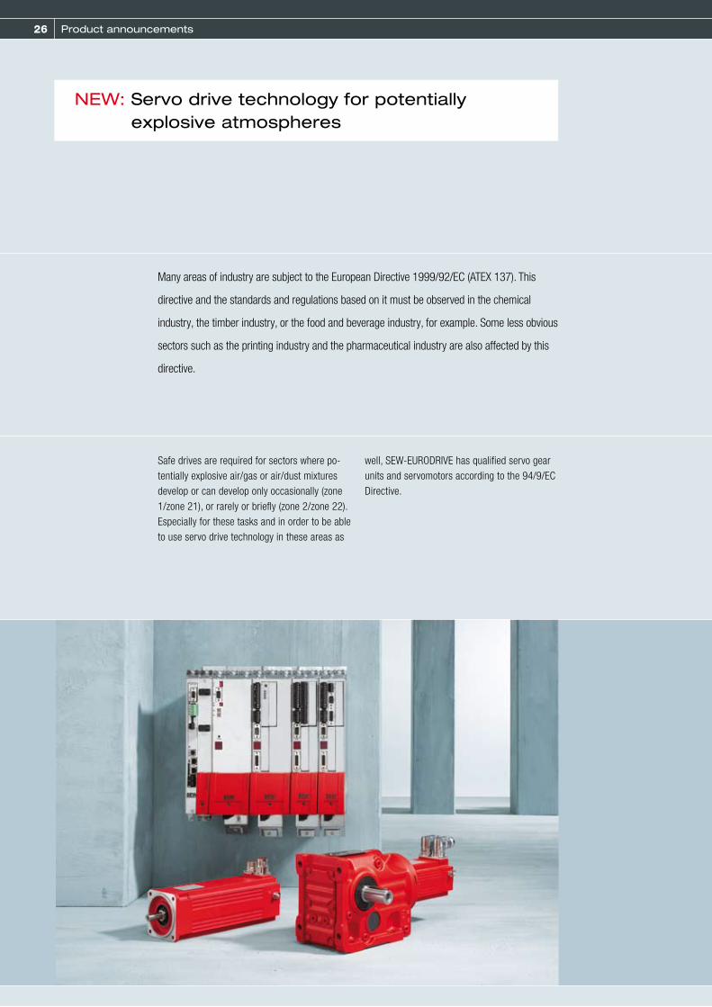
Many areas of industry are subject to the European Directive 1999/92/EC (ATEX 137). This
directive and the standards and regulations based on it must be observed in the chemical
industry, the timber industry, or the food and beverage industry, for example. Some less obvious
sectors such as the printing industry and the pharmaceutical industry are also affected by this
directive.
NEW: Servo drive technology for potentially explosive atmospheres
Safe drives are required for sectors where po-tentially explosive air/gas or air/dust mixtures develop or can develop only occasionally (zone 1/zone 21), or rarely or briefly (zone 2/zone 22). Especially for these tasks and in order to be able to use servo drive technology in these areas as
well, SEW-EURODRIVE has qualified servo gear units and servomotors according to the 94/9/EC Directive.
27
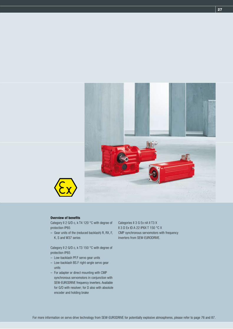
Overview of benefitsCategory II 2 G/D c, k T4 120 °C with degree of protection IP65– Gear units of the (reduced backlash) R, RX, F,
K, S and W37 series
Category II 2 G/D c, k T3 150 °C with degree of protection IP65– Low-backlash PF.F servo gear units– Low-backlash BS.F right-angle servo gear
units– For adapter or direct mounting with CMP
synchronous servomotors in conjunction with SEW-EURODRIVE frequency inverters. Available for G/D with resolver; for D also with absolute encoder and holding brake
Categories II 3 G Ex nA II T3 XII 3 D Ex tD A 22 IP6X T 150 °C XCMP synchronous servomotors with frequency inverters from SEW-EURODRIVE.
For more information on servo drive technology from SEW-EURODRIVE for potentially explosive atmospheres, please refer to page 76 and 87.

28 Gearmotors and frequency inverters
CLASSIC – Gearmotors and frequency inverters
The SEW-EURODRIVE modular concept offers millions of combinations and, as a result,
provides any user the perfect prerequisite for choosing the drive that optimally suits the
specific machine or system and for operating it according to the specific conditions:
– Individually depending on the required speed and torque range
– According to the space and type of mounting
– Adjusted to the ambient conditions
29
To solve your drive task, our gearmotors are available in an unrivaled number of sizes and reduction ratios, either in axially parallel design or with angle-shaped power flow.Torque and permissible overhung loads are in-comparably high in relation to the structural volume of the motor. This was made possible by the compact and extremely rigid housing with its low weight and optimum magnetic flux. The
sealing surfaces are not subject to any load pressure as the force flows through the single-piece housing. Our gearmotors are especially short since the motor shaft is part of the first gear unit stage. As a result, SEW-EURODRIVE gear units and gearmotors require little space, which is a real plus when it comes to design-ing systems.
Our gear units and gearmotors offer more than just a wide variety and high power density. They are also reliable, have a high overload capacity and a long service life. These features are the
result of our serial production proficiency and uncompromising high-quality work. Oil seals, flexible surface gaskets and optimized housing design prevent leaks and increase service life.
The modular concept stands for:
Variety and quality – power density and reduced length
Our drives enable maximum flexibility in com-bination with our drive electronics. The drive electronics perfectly matches the mechanics and optimally blends into the systems offered by
SEW-EURODRIVE. Just like the mechanical components, the entire drive electronics is developed, produced and assembled at SEW-EURODRIVE.
1

30 Gearmotors and frequency inverters
Standard gear units / standard gearmotors
The six single-stage and fourteen two- and three-stage sizes of SEW-EURODRIVE helical gearmotors ensure an optimum balance be-tween power and space requirements. The tried and proven modular system together with our stringent quality criteria make it possible for SEW-EURODRIVE to supply torques and gear ratios that are incomparably closely spaced and diverse. This exceptional design diversity sets new standards in this field of drive engineering.
All our gear units and gearmotors offer a finely tuned performance range and therefore provide excellent economic prerequisites for every application.Available designs:– Single-stage or multi-stage– Foot- or flange-mounted– Foot- and flange-mounted– Flange-mounted with extended bearing hub
Helical gear units / helical gearmotors
RX series (single-stage)
For high output speeds, the exclusively single-stage gear units RX57 to RX107 offer compact solutions for your system design.
Technical data
Gear unit reduction ratio [i] 1.30 ... 8.65
Output torque [Nm] 36 ... 830
Motor power range [kW] 0.12 ... 45

31
RM series
RM gearmotors with extended output bearinghub are a special type of helical gear unit.They are specifically designed for agitatingapplications and can be used in applicationssubject to high overhung and axial loads as
well as flexural torque. The data below appliesfor standard helical gearmotors.
Technical data
Gear unit reduction ratio [i] 4.29 ... 289.74
Multi-stage gear unit reduction ratio [i] 134 ... 27001
Output torque [Nm] 270 ... 18000
Motor power range [kW] 0.12 ... 160
R series (two- and three-stage)
The complete program of helical gearmotors provides the optimum size and power solution for every drive task. And for operators with a ”weight-watching“ issue, our multi-stage gear units provide a particularly special solution. Thanks to their die-cast aluminum design, the models R07, R17 and R27 are three particu-larly efficient lightweights – ideal as satellite
drives and for use in light machine construc-tions. Reduced backlash helical gear units are also available for particularly precise require-ments.
Technical data
Gear unit reduction ratio [i] 3.21 ... 289.74
Multi-stage gear unit reduction ratio [i] 90 ... 27001
Output torque [Nm] 31 ... 18000
Motor power range [kW] 0.09 ... 160
1

32 Gearmotors and frequency inverters
Standard gear units / standard gearmotors
F series (two- and three-stage)
Our extra-slim parallel shaft helical gearmotors are the perfect solution when space is limited. The many different sizes and designs ensure that the gearmotors can be used in a wide variety of applications even under the most unfavorable conditions. Parallel shaft helical gearmotors are typically used in conveyor and materials processing applications. They are available as foot-, flange- or shaft-mounted versions. Reduced backlash parallel shaft heli-cal gear units are also available on request for precise positioning tasks.
Available designs:– Foot- or flange-mounted– B5 or B14 flange-mounted– Solid or hollow shaft– Hollow shaft with keyed connection, shrink
disk, splined hollow shaft or TorqLOC®
Technical data
Gear unit reduction ratio [i] 3.77 ... 281.71
Multi-stage gear unit reduction ratio [i] 87 ... 31434
Output torque [Nm] 87 ... 18000 (also in reduced backlash version)
Motor power range [kW] 0.12 ... 200
K series (three-stage)
Our helical-bevel gear units provide a high de-gree of efficiency of over 96 % in both torque directions and at all input speeds. High-endur-ance gearing enables high-torque, wear-free drive. The remarkably high level of efficiency makes the helical-bevel gearmotors energy-saving angular gear drives. As they also have a long maintenance-free service life, they can be used with AC asynchronous motors, asynchro-nous and synchronous servomotors in every application. A reduced backlash version is available for precise positioning tasks.
Available designs:– Foot- or flange-mounted– B5 or B14 flange-mounted– Solid or hollow shaft– Hollow shaft with keyed connection, shrink
disk, splined hollow shaft or TorqLOC®
Technical data
Gear unit reduction ratio [i] 3.98 ... 197.37
Multi-stage gear unit reduction ratio [i] 94 ... 32625
Output torque [Nm] 125 ... 50000 (also in reduced backlash version)
Motor power range [kW] 0.12 ... 200
Parallel shaft helical gear units and gearmotors
Helical-bevel gear units and gearmotors

33
S series
Our helical-worm gear units are helical gear/worm combinations that are significantly more efficient than straightforward worm gear units. Due to their excellent economic efficiency, these drives can be used in every branch of industry – tailored individually to torque and speed requirements. The gear ratios afforded by the worm gear stage and the low noise lev-els during operation make these gearmotors ideal low-cost solutions for simple applica-tions.
Available designs:– Foot- or flange-mounted– B5 or B14 flange-mounted– Solid or hollow shaft– Hollow shaft with keyed connection, shrink
disks, splining or TorqLOC®
Technical data
Gear unit reduction ratio [i] 6.80 ... 288.00
Multi-stage gear unit reduction ratio [i] 110 ... 33818
Output torque [Nm] 43 ... 4000
Motor power range [kW] 0.12 ... 22
W series
W series gearmotors are robust, single-stage right-angle gearmotors with SPIROPLAN® gearing. They distinguish themselves from helical-worm gear units by the material com-bination used in the gearing (steel/steel), the special tooth meshing ratios and the aluminum housing. SPIROPLAN® right-angle gearmotors are wear-free, very quiet-running and light-weight. Due to their extremely short design and aluminum housing, these gearmotors en-able compact and lightweight drive solutions. The wear-free gearing and lubrication that
lasts the entire service life of the gearmotor permit long maintenance-free operation. Oil filling is independent of the mounting position, which allows SPIROPLAN® right-angle gearmo-tors to be installed in any mounting position without altering the quantity of oil. The identical hole distances in the foot and face as well as the identical shaft centers between the foot and face make for a wide range of mounting options.Available designs:– Foot- or flange-mounted– B5 or B14 flange-mounted
Technical data
Gear unit reduction ratio [i] 3.20 ... 75.00
Output torque [Nm] 12 ... 180
Motor power range [kW] 0.09 ... 3.0
Helical-worm gear untis and gearmotors
SPIROPLAN® right-angle gearmotors
1

34 Gearmotors and frequency inverters
Accessories and options
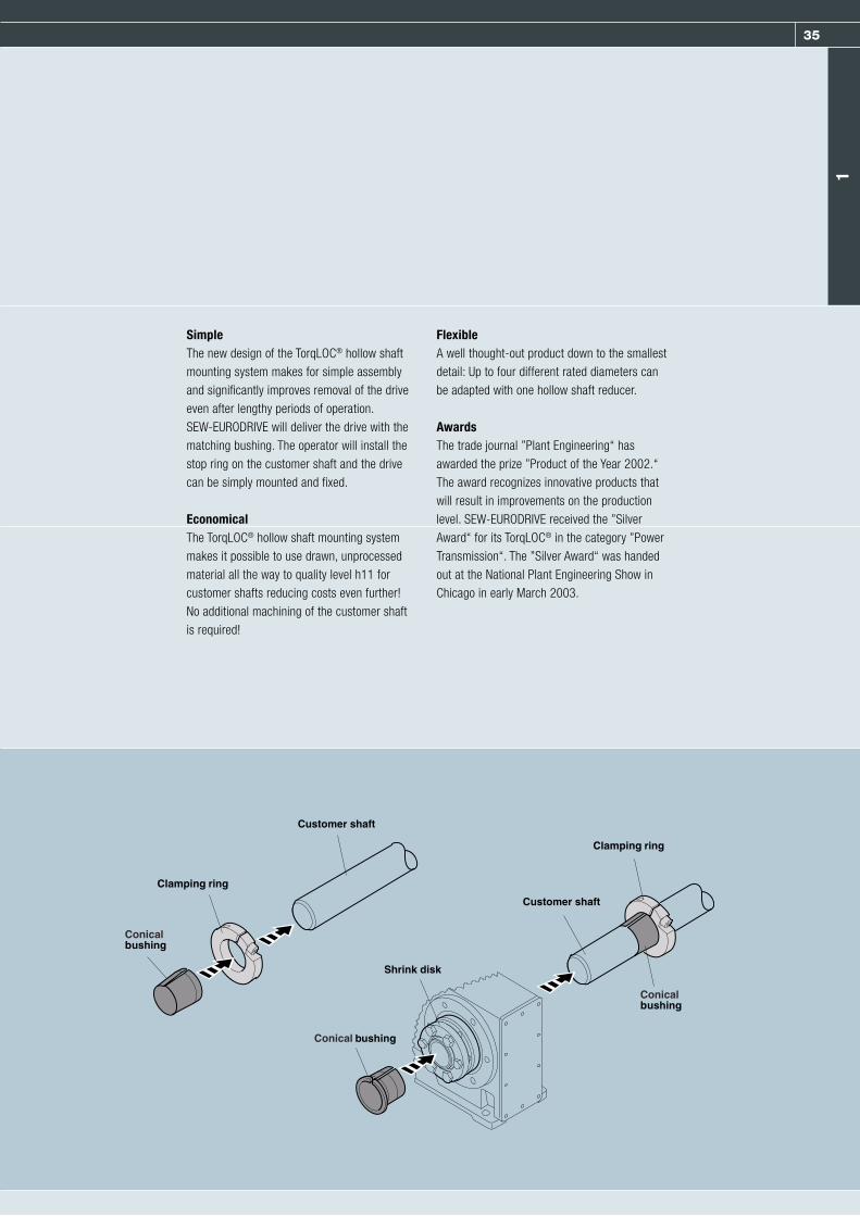
Optional for parallel shaft helical, helical-bevel and helical-worm gear units. The TorqLOC® hol-low shaft mounting system is used for achieving a non-positive connection between the custom-er’s shaft and the hollow shaft in the gearunit. As a result, the TorqLOC® hollow shaft
mounting system is an alternative to the existing hollow shaft with shrink disk, hollow shaft with key and the splined hollow shaft. The TorqLOC® hollow shaft mounting system provides the ad-vantages of easy installation and de-installation, and saving costs.
TorqLOC® hollow shaft mounting system
35
SimpleThe new design of the TorqLOC® hollow shaft mounting system makes for simple assembly and significantly improves removal of the drive even after lengthy periods of operation.SEW-EURODRIVE will deliver the drive with the matching bushing. The operator will install the stop ring on the customer shaft and the drive can be simply mounted and fixed.
EconomicalThe TorqLOC® hollow shaft mounting system makes it possible to use drawn, unprocessed material all the way to quality level h11 for customer shafts reducing costs even further! No additional machining of the customer shaft is required!
FlexibleA well thought-out product down to the smallest detail: Up to four different rated diameters can be adapted with one hollow shaft reducer.
AwardsThe trade journal ”Plant Engineering“ has awarded the prize ”Product of the Year 2002.“ The award recognizes innovative products that will result in improvements on the production level. SEW-EURODRIVE received the ”Silver Award“ for its TorqLOC® in the category ”Power Transmission“. The ”Silver Award“ was handed out at the National Plant Engineering Show in Chicago in early March 2003.
1

36 Gearmotors and frequency inverters
Overhead trolley drives
Overhead trolley drives are an variable and efficient means of transport used in many
industries. The decisive factors for the performance, conveying speed and load carrying
capacity of these drives are the transport material and the application. Drives for overhead
trolley systems from SEW-EURODRIVE are therefore divided into light-load and heavy-load.
Light load range, drives of the HW30 / HS40 series
Light load drives are quiet and comply with C1 guideline standards (VDI guideline 3643). They work with a reliable disengageable coupling and provide the following advantages:
– Low-maintenance for a high level of availability and productivity
– Smooth running for operation without vibration
– Low-noise for use in manual work stations– Compact for space-saving installation
Technical data
Type Maximumtorque [Nm]
Permittedwheel load [N]
Force application x[mm]
Speed with carrying wheel Ø 125 mm [m/min]
Gear ratio Shaft d x l
[mm]
HW 30 70 5600 13 7.3 ... 67 8.2 ... 75 20 x 3525 x 35
HS 40 130 6500 13 2.7 ... 75 7.28 ... 201 20 x 3525 x 35

37
Heavy load range, drives of the HS / HK series
The heavy load range in particular has seen a clear trend toward increasing permitted work loads. SEW-EURODRIVE has expanded the HK series due to the improved efficiency of helical-bevel gear units over helical-worm gear units. Overhead trolley drives with helical-bevel gear units (HK series) can now be used for wheel
loads up to 40,000 N. Power consumption is reduced, particularly when the MOVITRANS® system for contactless energy transfer is also used. As a result, systems operate with greater economic efficiency.
Technical data
Type Maximum torque[Nm]
Permitted wheel load[N]
Force application x[mm]
Speed with carrying wheel Gear ratio Shaft d x l [mm]
Ø 200 mm[m/min]
Ø 250 mm[m/min]
Ø 300 mm[m/min]
HS 41 185 10000 13 4.4 ... 120 – – 7.28 ... 201 25 x 35
HS 50 300 15000 18 28
4.4 ... 120 5.4 ... 151 – 7.28 ... 201 30 x 6035 x 70
HS 60 600 25000 28 4.0 ... 116 5.1 ... 145 6.1 ... 175 7.56 ... 217.41 45 x 90
HK 30 200 10000 13 8.3 ... 68 – – 13.1 ... 106.38 25 x 35
HK 40 400 18500 1828
6.7 ... 72 8.3 ... 90 – 12.2 ... 131.87 30 x 6035 x 70
HK 50 600 25000 28 6.1 ... 66 7.6 ... 83 9.1 ... 100 13.25 ... 145.14 45 x 90
HK 60 820 40000 32 6.1 ... 66 7.6 ... 83 9.1 ... 100 13.22 ... 144.79 55 x 110
1

38 Gearmotors and frequency inverters
Explosion-proof drives
SEW-EURODRIVEDriving the world
Drive Technology \ Drive Automation \ System Integration \ Services
How we’re driving the world
ArgentinaPhone +54 3327 4572-84Fax +54 3327 [email protected] +61 3 9933-1000Fax +61 3 [email protected] +43 1 617 55 00-0Fax +43 1 617 55 [email protected] +375 17 298 38 50Fax +375 17 298 [email protected] +32 10 231-311Fax +32 10 [email protected] +55 11 2489-9133Fax +55 11 [email protected] +1 905 791-1553Fax +1 905 [email protected] +56 2 75770-00Fax +56 2 [email protected] +86 22 25322612Fax +86 22 [email protected] +57 1 54750-50Fax +57 1 [email protected] RepublicPhone +420 255709601Fax +420 [email protected]
DenmarkPhone +45 43 9585-00Fax +45 43 [email protected] +358 201 589 300Fax +358 3 [email protected] +33 3 88 73 67 00Fax +33 3 88 73 66 [email protected] BritainPhone +44 1924 893-855Fax +44 1924 [email protected] KongPhone +852 36902200Fax +852 [email protected] +36 1 437 06-58Fax +36 1 437 [email protected] +91 265 2831086Fax +91 265 [email protected] +39 02 96 9801Fax +39 02 96 [email protected] +81 538 373811Fax +81 538 [email protected] +60 7 3549409Fax +60 7 [email protected] +52 442 1030-300 Fax +52 442 [email protected]
NetherlandsPhone +31 10 4463-700Fax +31 10 [email protected] ZealandPhone +64 9 2745627Fax +64 9 [email protected] +47 69 241-020Fax +47 69 [email protected] +51 1 3495280Fax +51 1 [email protected] +48 42 6765300Fax +48 42 [email protected] +351 231 20 9670Fax +351 231 20 [email protected] +7 812 3332522Fax +7 812 [email protected] +65 68621701Fax +65 [email protected] +421 2 33595202Fax +421 2 [email protected] AfricaPhone +27 11 248-7000Fax +27 11 [email protected] KoreaPhone +82 31 492-8051Fax +82 31 [email protected]
SpainPhone +34 94 4318470Fax +34 94 [email protected] +46 36 344200Fax +46 36 [email protected] +41 61 41717-17Fax +41 61 [email protected] +66 38 454281Fax +66 38 [email protected] +90 216 4419163Fax +90 216 [email protected] +380 56 370 3211Fax +380 56 372 [email protected] +598 2 90181-89Fax +598 2 [email protected] +1 864 439-7537Fax +1 864 [email protected] +58 241 832-9804Fax +58 241 [email protected]
SEW-EURODRIVE is right there for you:
SEW-EURODRIVE GmbH & Co KGP.O.Box 30 23D-76642 Bruchsal/GermanyPhone +49 7251 75-0Fax +49 7251 [email protected]
j www.sew-eurodrive.com
1661
961
7 /
1008
Drive Technology \ Drive Automation \ System Integration \ Services
Certified and safeServo drives for potentially explosive atmospheres
5
Possible error source Prerequisite
1 Guaranteeing unit safety during normal Gear units and motors in this categoryoperation and in the event of rare unit malfunctions (two independent unit errors – 1G (gas), for use in zones 0, 1 and 2must be controlled) – 1D (dust), for use in zones 20, 21 and 22
Category 1 units for use in zones 0 or 20are not available from SEW-EURODRIVE.
2 Guaranteeing unit safety during normal Gear units and motors in this categoryoperation and additionally for expected – 2G (gas), for use in zones 1 and 2malfunctions (error) – 2D (dust), for use in zones 21 and 22
– 2GD (gas/dust), for use in zones 1, 2 or 21, 22
3 Guaranteeing unit safety during standard Gear units and motors in this categoryoperation – 3G (gas), for use in zone 2
– 3D (dust), for use in zone 22– 3GD (gas/dust), for use in zones 2 or 22
Safety requirements and unit categories
All resources are divided into three categoriesdepending on the safety requirements. The manufacturer of the unit assigns the category to the relevant equipment. The criteria used forthis purpose are applicability and safety in theevent of a malfunction. Possible error sources
are examined that might or may occur duringoperation.
The assignment of categories to zones is speci-fied in EU Directive 1999/92/EC. Units with higher categories assigned to them (e.g. II2D)
can also be used in zones where units with lowercategories must be used (e.g. II3D). The applica-bility of the entire drive for a specific zone resultsfrom the drive component with the lowest category.
Category
Gas Dust
SEW-EURODRIVE offers no products for zones 0 and 20
Applicable categoriesZones
Zone structure
1661 9617_ATEX_EN.qxd:1157 3007_IG X_6-Seiter_DE 18.11.2008 13:21 Uhr Seite 5
Directive 94/9/EC or ATEX lays down new regu-lations for explosion protection in all types of devices for the European market. This directive applies to gearmotors and motors. As of July 1, 2003, Directive 94/9/EC applies without restric-tions to the use of gearmotors and motorswithin the European Union. Other European coun-tries, such as Switzerland, have since come into
line with this regulation. SEW-EURODRIVE offers gearmotors and motors for operation in poten-tially explosive atmosphere only in accordance with the relevant ATEX regulation. This also ap-plies to options and accessories in explosion-proof design.
Explosion protection in compliance with ATEX
For innovations in SEW-EURODRIVE’s servo drive technology for potentially explosive atmospheres, please refer to pages 27/28

39
Explosion-proof drives
Operating systems and machines in areas with potentially explosive air / gas or air / dust mix-tures requires special. Appropriate regulationsand standards regulate the use of tools and fixtures in danger zones. They also prescribe the quality prerequisites that must be met by drive manufacturers.
Technical data
Category / zone Type Power range [kW]
II3D / II3GD II3D / II3GD R..D../II3... Helical gearmotorsF..D../II3... Parallel shaft helical gearmotors 0.12 ... 75K..D../II3... Helical-bevel gearmotorsW..D../II3... SPIROPLAN® gearmotors 0.12 ... 0.75S..D../II3... Helical-worm gearmotors 0.12 ... 22
II2D II2D R..D../II2D Helical gearmotorsF..D../II2D Parallel shaft helical gearmotors 0.37 ... 22K..D../II2D Helical-bevel gearmotorsS..D../II2D Helical-worm gearmotors 0.37 ... 0.75W..D../II2D SPIROPLAN® gearmotors 0.37 ... 22
II2G II2G R..D../II2G Helical gearmotorsF..D../II2G Parallel shaft helical gearmotors 0.15 ... 16K..DG/II2D Helical-bevel gearmotorsW..D../II2G SPIROPLAN® gearmotors 0.15 ... 0.75S..D../II2G Helical-worm gearmotors 0.15 ... 16
II2G_T4 II2G_T4 R..D../II2G_T4 Helical gearmotorsF..D../II2G_T4 Parallel shaft helical gearmotors 0.15 ... 1.5K..D../II2G_T4 Helical-bevel gearmotorsW..D../II2G_T4 SPIROPLAN® gearmotors 0.15 ... 0.55S..D../II2G_T4 Helical-worm gearmotors 0.15 ... 1.5
1
SEW-EURODRIVE—Driving the world40 Gearmotors and frequency inverters
Overview of the advantages this combination of-fers compared to an AC asynchronous motor in explosion protection “d” (EN 60079-1; flame-proof enclosure):
– High efficiency– Lighter weight– Shortest possible delivery times, high avail-
ability
– Certified for operation with frequency inverters from SEW-EURODRIVE
– Suitable for pump and fan drives– Supplied by one source, from a manufacturer
that offers both components itself
Compared to the rated supply torque, the per-mitted load value for operation with a frequency inverter was reduced to the shown values to ensure thermally safe operation; current values
for 400 V / 50 Hz voltage in star connection; the current values for delta connection 230 V / 50 Hz (or 400 V / 87 Hz) must be converted with factor √
–3.
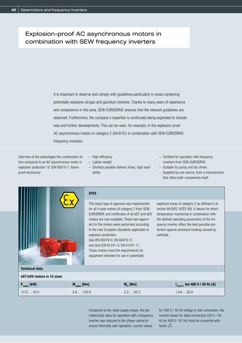
It is important to observe and comply with guidelines particularly in areas containing
potentially-explosive air/gas and gas/dust mixtures. Thanks to many years of experience
and competence in this area, SEW-EURODRIVE ensures that the relevant guidelines are
observed. Furthermore, the company’s expertise is continually being expanded to include
new and further developments. This can be seen, for example, in the explosion-proof
AC asynchronous motors in category 2 (94/9 EC) in combination with SEW-EURODRIVE
frequency inverters.
Explosion-proof AC asynchronous motors in combination with SEW frequency inverters
ATEX
This basic type of approval was implemented for all 4-pole motors of category 2 from SEW-EURODRIVE and certificates of all eDT and eDV motors are now available. These new approv-als for the motors were performed according to the new European standards applicable to explosion protection: Gas (EN 60079-0; EN 60079-7)and dust (EN 61241-0; EN 61241-1).These motors meet the requirements for equipment intended for use in potentially
explosive areas of category 2 as defined in di-rective 94/9/EC (ATEX 95). A device for direct temperature monitoring in combination with the defined operating parameters of the fre-quency inverter offers the best possible pro-tection against excessive heating caused by overload.
Technical data
eDT/eDV motors in 15 sizes
Psupply [kW] Msupply [Nm] MFI [Nm] Irated-FI bei 400 V / 50 Hz [A]
0.37… 16.0 2.6 … 103.9 2.2 … 85.3 1.04… 26.8

41
We regard each individual component as part of the system.
SEW-EURODRIVE—Driving the world
A chain is only as strong as its weakest link. This also applies to production, sales and logistics. As a leading drive
technology specialist, we help you to keep your systems running – with drive solutions that guarantee the highest
degree of system availability and ensure that your business is successful. This is what we call Drive 360° – Seeing
the big picture: From system availability to problem-solving competence, from low operating costs over energy
efficiency to the complete system that handles all your tasks.
www.sew-eurodrive.com
Seeing the big picture.
Seeing the big picture.
Seeing the big picture.
Seeing the big picture.

42 Gearmotors and frequency inverters
DAS series
Solutions for dry hygienic areas:Aseptic gearmotors of the DAS series for drive solutions without fans and smooth surfaces:– Motors with degree of protection IP66
(brakemotors IP65)– Motor corrosion protection:
KS internal treatment– OS2 to OS4 surface protection
(see also page 44)– Motor protection thermistor in thermal class
F, TH thermostat relay as option– IS plug connector
Technical data
Type Power [kW] in operating mode
S1 = Continuous duty S3 = Intermittent duty
60 % 40 % 25 %
DAS80K4 0.25 0.3 0.37 0.55
DAS80N4 0.37 0.45 0.55 0.75
DAS90S4 0.55 0.75 0.9 1.1
DAS90L4 0.75 0.95 1.1 1.5
DAS100M4 1.1 1.35 1.7 2.2
DAS100L4 1.5 1.85 2.3 3.0
Aseptic gearmotors
Particularly high requirements are placed on hygiene in the beverage and food industry as
well as in the chemical and pharmaceutical industry. The necessary cleaning processes
and the use of aggressive cleansing and disinfectant agents can considerably affect the
drive solutions in such environments.

43
ASEPTICplus drive package
Standard motors are not the first choice for hygienic production areas because they usually come equipped with cooling fins and fans where dirt can accumulate and germs and bacteria can be distributed by air swirls.
SEW-EURODRIVE offers the perfect solution also for such areas of application: DAS series aseptic motors with ASEPTICplus drive package.
Solutions for hygienic production areas:
– Motors with degree of protection IP69K (brakemotors IP65)– OS4 surface protection– Contour recesses with sprayed-on rubber– Double oil seals (if technically feasible) at output made of Viton (FKM)– Stainless steel breather valve – Pressure compensation membrane– Cable entry with screw plugs made of stainless steel– Gear unit output shaft made of stainless steel as solid shaft, hollow shaft with key or TorqLOC for gear unit types:
R17-97, F37-97, K37-97, S37-97 and W30– All retaining parts at the output shaft, such as screws, keys, shrink disk, etc., made of steel
1

44 Gearmotors and frequency inverters
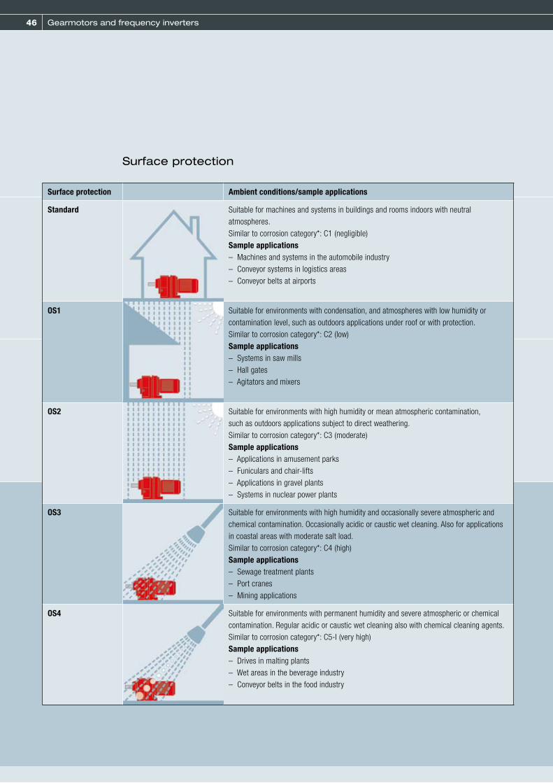
OS surface protectionIn addition to standard surface protection, motors and gear units also have the option of surface protection OS1, OS2, OS3 or OS4 making the gearmotors well equipped for operation under various ambient conditions.
SEW-EURODRIVE offers corrosion and surface protection for operating motors and gear
units under special ambient conditions. The combination of these protection measures
ensures the optimum protection for motors and gear units.
KS corrosion protectionKS corrosion protection for motors comprises the following measures:– All retaining screws that are loosened during
operation are made of stainless steel.– The nameplates are made of stainless steel.
Various motor parts are coated with a top coat.
– Flange contact surfaces and shaft ends are treated with a temporary anti-corrosion agent.
– Additional measures for brakemotors.
KS corrosion protection and OS surface protectionfor all standard motors and gear units

45
Measures for internal treatment and standard parts
Brakes with pressureplate made of noncorrosivematerial
Special interiorsurface coating
Rustproofnameplates
NOCO® fluid, thecontact corrosion
inhibitor
Output shaft madeof stainless steel
RS bearing for IP56
Special interior surface coating
Non-corrosiveretaining parts
Special interiorsurface coating
Rustproof breathervalves
Optional coating atdrive shaft end(in the area of theradial oil seal seat)
1
46 Gearmotors and frequency inverters
Surface protection Ambient conditions/sample applications
Standard Suitable for machines and systems in buildings and rooms indoors with neutral atmospheres.Similar to corrosion category*: C1 (negligible)Sample applications– Machines and systems in the automobile industry– Conveyor systems in logistics areas– Conveyor belts at airports
OS1 Suitable for environments with condensation, and atmospheres with low humidity or contamination level, such as outdoors applications under roof or with protection.Similar to corrosion category*: C2 (low)Sample applications– Systems in saw mills– Hall gates– Agitators and mixers
OS2 Suitable for environments with high humidity or mean atmospheric contamination, such as outdoors applications subject to direct weathering.Similar to corrosion category*: C3 (moderate)Sample applications– Applications in amusement parks– Funiculars and chair-lifts– Applications in gravel plants– Systems in nuclear power plants
OS3 Suitable for environments with high humidity and occasionally severe atmospheric and chemical contamination. Occasionally acidic or caustic wet cleaning. Also for applications in coastal areas with moderate salt load.Similar to corrosion category*: C4 (high)Sample applications– Sewage treatment plants– Port cranes– Mining applications
OS4 Suitable for environments with permanent humidity and severe atmospheric or chemical contamination. Regular acidic or caustic wet cleaning also with chemical cleaning agents.Similar to corrosion category*: C5-I (very high)Sample applications– Drives in malting plants– Wet areas in the beverage industry– Conveyor belts in the food industry
Surface protection

47
Surface protection Ambient conditions/sample applications
DAS series aseptic motorsOS2-OS4 as option
Suitable for dry or humid hygienic areas with mean atmospheric contamination. Also suitable for particularly dusty environments.Similar to corrosion category*: C3 (moderate)Sample applications– Applications in clean rooms– Machines in the cosmetic and pharmaceutical industry– Systems for processing cereal and flour (without Ex protection)– Conveyor belts in cement plants
DAS series aseptic motors with ASEPTICplus drive packageOS4
Suitable for hygienic areas in the food and beverage industry with permanent humidity and regular acidic and wet cleaning with chemical cleaning agents. Cleaning with compressive stress up to 80 bar.Similar to corrosion category*: C5-I (very high)Sample applications– Hygienic and aseptic conveyors in the beverage industry– Systems in cheese dairies and butcher shops– “Splash zones” in the food industry
* according to DIN EN ISO 12944-2
1

48 Gearmotors and frequency inverters
Standard and energy efficient motors:DRS / DRE / DRP
The new modular system of asynchronous AC motors from SEW-EURODRIVE is a development based on the established motor series. The new DR series AC motors combine the entire range of required motor efficiency levels as well as energy efficient motors making it a future-proof innova-tion of the highest quality.
In the development of energy efficient motors, SEW-EURODRIVE became the first company in the world to succeed in using die-cast copper technology in industrial high-volume series production in 2002. The modular DR motor
system from SEW-EURODRIVE offers three different brake sizes per motor size and cost- optimized encoders integrated in the motor.
All other additional features of the new DR series are available in all energy efficiency levels. The DR motor supports any energy efficiency stan-dard worldwide and even already meets the up-coming IEC standard. They bring a whole range of unique benefits to planners and users. One single series for millions of drive combina-tions.
Modular DR motor system
49
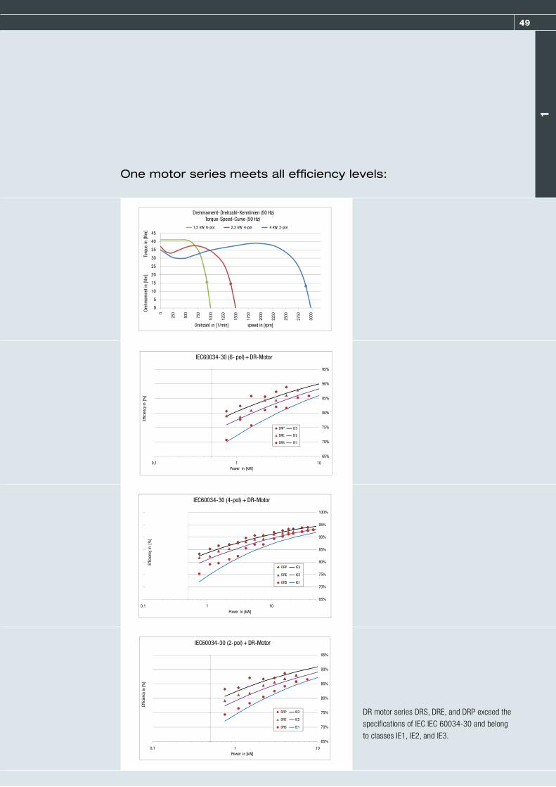
One motor series meets all efficiency levels:
DR motor series DRS, DRE, and DRP exceed the specifications of IEC IEC 60034-30 and belong to classes IE1, IE2, and IE3.
1
Effic
ienc
y Ef
ficie
ncy
Effic
ienc
y
Power
Power
Power
Effic
ienc
y Ef
ficie
ncy
Effic
ienc
y
Power
Power
Power
Effic
ienc
y Ef
ficie
ncy
Effic
ienc
y
Power
Power
Power
Effic
ienc
y Ef
ficie
ncy
Effic
ienc
y
Power
Power
Power

50
Gearmotors and frequency inverters
AC motors of energy efficiency classes IE
DRS series DRE series DRP series
The DRS motor in the modu-lar DR motor system is a motor that meets the standard efficiency level. The motors are marked with IE1 according to IEC 60034 T30.
The DRE motor in the modular DR motor system is a motor that meets High Efficency requirements. The motors are marked with IE2 according to IEC 60034 T30.
The DRP motor in the modular DR motor system is a motor that meets Premium Efficency requirements. The motors are marked with IE3 according to IEC 60034 T30.
Technical data
Sizes 71 … 225315
80 … 225315
90 … 225315
Lengths K, S, M, MC, L, LC
Power 4-pole [kW] 0.37 … 55110 … 200
0.75 … 45110 … 200
0.75 … 3790 … 160
Frequenzy [Hz] 50, 60 und 50/60
Efficiency logo International: IE1 International: IE2, North America1): ,
International: IE3, North America1): ,
1) North America in preparation

51
The BE brake is based on the extremely suc-cessful BM(G) brake, but was further developed in many aspects. The brake size has so far been unalterably linked to the motor size. ”Less“ brake is only possible by reducing the braking torque with a modified brake spring.
The new combination options of DR motors with BE brakes are no longer subject to this unalter-ability. The DR motor can be combined with two or three different BE brake sizes.
Modular brake system
The brake of your choice –
extract from the brake combination options:
Brake combinations
Depending on the braking torque or braking work required, the DR motor can be combined with the ideal BE brake. Brake mounting to motors size 90 and larger offers another spe-cial feature. The brake itself is mounted on a friction plate, which only has to be attached to
the endshield. Without opening the motor, the unit can now be demounted and replaced – also by a larger or smaller brake.
Technical data
Motor type Bake type Wtot [106 J] Braking torque grading [Nm]
… … … …
DR.90 BE1 120 5 7 10
BE2 165 7 10 14 20
BE5 260 14 20 28 40
DR.100 BE2 165 10 14 20
BE5 260 14 20 28 40 55
… … …
BE5
BE2BE1
1
52 Gearmotors and frequency inverters
Built-in encoders
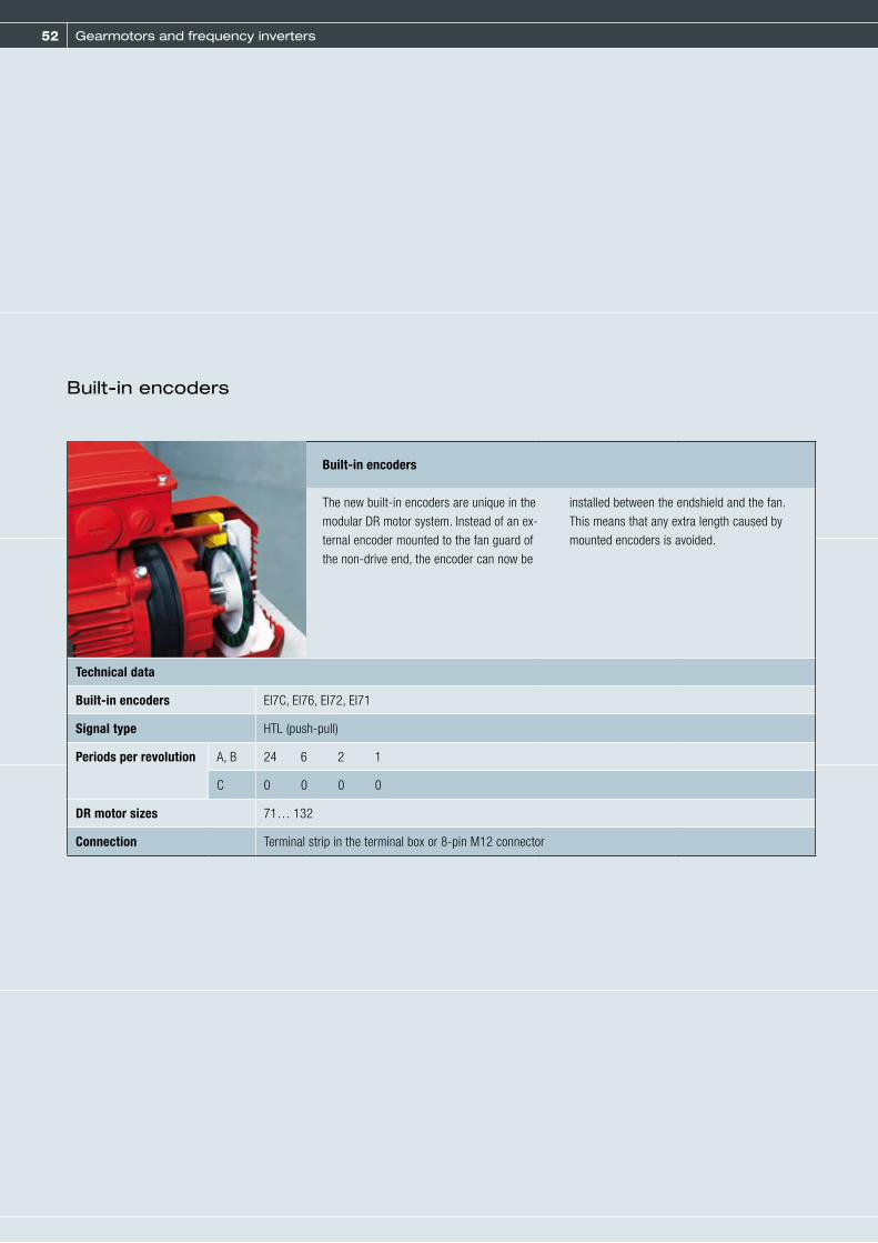
Built-in encoders
The new built-in encoders are unique in the modular DR motor system. Instead of an ex-ternal encoder mounted to the fan guard of the non-drive end, the encoder can now be
installed between the endshield and the fan. This means that any extra length caused by mounted encoders is avoided.
Technical data
Built-in encoders EI7C, EI76, EI72, EI71
Signal type HTL (push-pull)
Periods per revolution A, B 24 6 2 1
C 0 0 0 0
DR motor sizes 71… 132
Connection Terminal strip in the terminal box or 8-pin M12 connector

53
Other options Description
Mechanicalattachments
All versions that can be mounted to the DR motor using additional elements:BE.. Brake with brake size, scaled in steps of 10 NmHF, HR Manual brake release, lockable or automatic disengaging/RS Backstop instead of a brake/MSW MOVI-SWITCH®, integrated switching and protection function/MM.. MOVIMOT®, integrated frequency inverter
Temperature sensor,temperature detection
All versions that are offered with additional elements in the winding:/TF 3 temperature sensors (positive coefficient thermistor or PTC resistor) connected in series/TH 3 thermostats (bimetallic switches) in series/KY 1 temperature sensor KTY84-130/PT 1 or 3 temperature sensors PT100
Ventilation All versions in conjunction with cooling/ventilation on the DR motor:/V Forced cooling fan, IP66, AC voltage range or DC/Z Additional flywheel mass (flywheel fan)/AL Metal fan/U Non-ventilated (only without fan)/OL Non-ventilated (closed B side)/LF Air filter/C Protective cover
Bearings All DR315 motors in conjunction with the bearing function:/NS Lubrication device/ERF Reinforced bearing for high overhung loads (only with NS)/NIB Insulated bearing (B-side)
Connection All designs in conjunction with connection alternatives/IS Integrated plug connector/AS.. etc. Installed plug connectors of all kinds/KCC Terminal strip with cage clamps/KC1 C1-compliant connection of electrified monorail system (VDI RL 3643)
Encoder
All designs in conjunction with mounted encoders of various electrical interfaces:/ES7. Mount-on encoder DR71 ... 132/EG7. Mount-on encoder DR160 ... 225/XV.. Mounting or encoder adapter of encoders not included in the SEW portfolio
Encoder All designs in conjunction with condition monitoring/DUB Brake monitoring for function and/or wear/DUV Vibration monitoring
Other Other designs/DH Condensation drain hole/2W Second shaft end on the motor/brakemotor/RI Reinforced winding insulation for frequency inverter operation > AC 500 V
The additional features of the DR motor and DR brakemotor are diverse and extensive. To provide
a better overview, they were combined in groups.
Additional features
1

54 Gearmotors and frequency inverters
DRL / DRM / DRK series AC motors
DRL motor
The DRL motor in the modular DR motor system is a motor that meets the standard efficiency level. The motors are marked with IE1 according to IEC 60034 T30. This motor is suited for high dynamic loads in addition to the high overload capacity of DR motors. This means the DRL motor fulfills allproperties of an asynchronous servomotor.
D1: Standard pinion shaft end: approx. 200 % MN
D2: Reinforced pinion shaft end: approx. 300 % MN
D3: IEC shaft end: approx. 350 % MN (max. Mbrake)
Technical data
Dynamic 1Dynamic 2 Dynamic 3
~ 200 % Mdyn / MN
~ 300 % Mdyn / MN
~ 350 % Mdyn / MN
Torques MN [Nm] 2.5 … 350
SizesLengths
71 … 225S, M, MC, L, LC
Speed classes [rpm] 1200, 1700, 2300, 3000
DRK motor
The DRK motor in the modular DR motor system is a single-phase motor that can be operated on a single-phase power supply (instead on the usual three-phase power supply). The DRK motor comes equipped with perating capacitor CB.
Technical data
SizesLengths
71 … 100S, M, L
Power 4-pole [kW]Frequency [Hz]
0.25 …. 1.5 50

55
DRM motor
The DRM motor in the modular DR motor system is a 12-pole motor that allows for thermally safe operation on a 3-phase mains supply, even if the rotor is blocked. The usual product designation ”torque motor” is also maintained for the DRM motor. Every torque motor is available with 2 rated torques. Rating 2 can be three times the torque of rating 1 but either only in S3/15 % cdf or in S1 continuous duty with forced cooling fan only.
Technical data
SizesLengths
71 … 160S, M, L
Rating 1Rating 2
S1S3/15 % or S1 with forced cooling fan
Rating 1 [Nm]Rating 2 [Nm]
0.4 … 3 1.2 … 9
1

56 Gearmotors and frequency inverters
MOVITRAC® B frequency inverter:Compact and versatile
When choosing a suitable application-specific frequency inverter, “unit modularity” and
“smaller dimensions” are among the most important criteria. SEW-EURODRIVE offers an
economical and compact solution: MOVITRAC® B, the lastest frequency inverter genera-
tion. The versatile unit concept and extensive expansion options allow for selecting exactly
those inverter functions that match the individual requirements of the specific application.
57
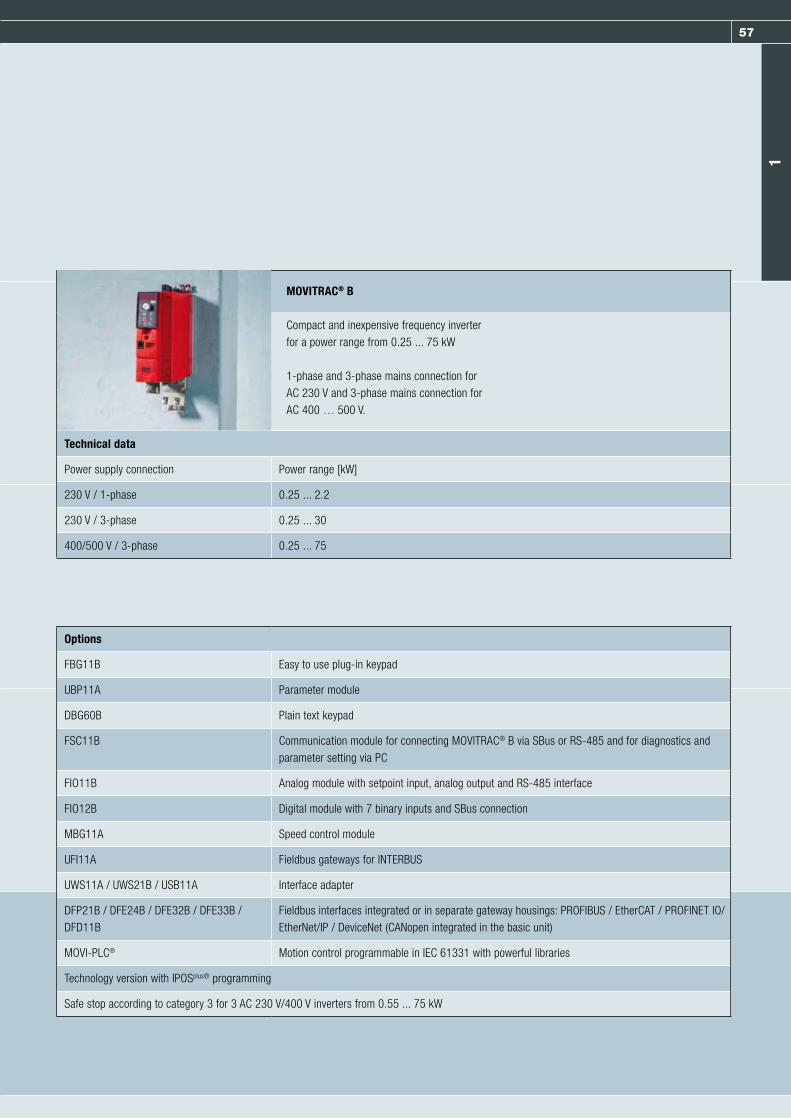
MOVITRAC® B
Compact and inexpensive frequency inverterfor a power range from 0.25 ... 75 kW
1-phase and 3-phase mains connection forAC 230 V and 3-phase mains connection forAC 400 … 500 V.
Technical data
Power supply connection Power range [kW]
230 V / 1-phase 0.25 ... 2.2
230 V / 3-phase 0.25 ... 30
400/500 V / 3-phase 0.25 ... 75
Options
FBG11B Easy to use plug-in keypad
UBP11A Parameter module
DBG60B Plain text keypad
FSC11B Communication module for connecting MOVITRAC® B via SBus or RS-485 and for diagnostics and parameter setting via PC
FIO11B Analog module with setpoint input, analog output and RS-485 interface
FIO12B Digital module with 7 binary inputs and SBus connection
MBG11A Speed control module
UFI11A Fieldbus gateways for INTERBUS
UWS11A / UWS21B / USB11A Interface adapter
DFP21B / DFE24B / DFE32B / DFE33B /DFD11B
Fieldbus interfaces integrated or in separate gateway housings: PROFIBUS / EtherCAT / PROFINET IO/ EtherNet/IP / DeviceNet (CANopen integrated in the basic unit)
MOVI-PLC® Motion control programmable in IEC 61331 with powerful libraries
Technology version with IPOSplus® programming
Safe stop according to category 3 for 3 AC 230 V/400 V inverters from 0.55 ... 75 kW
1

58 Gearmotors and frequency inverters
MOVIDRIVE® MDX 60/61B drive inverter
Drive inverters of the MOVIDRIVE® MDX60/61B series from SEW-EURODRIVE stand for
modern, digital inverter technology with comprehensive basic functions for a power range
from 0.55 to 315 kW, large overload capacity and modular unit concept. With MOVIDRIVE®,
AC motors can be used without limitations.
The levels of dynamic performance and con-trol quality that can now be achieved with MOVIDRIVE® for asynchronous AC motors were previously only possible using servo drives or DC motors. The integrated control functions and the possibility of upgrading the system with technol-
ogy and communication options results in drive systems that are designed for particularly high levels of efficiency in terms of their broad range of applications, project planning, startup and op-eration.

59
MOVIDRIVE® MDX 60/61B
High-performance inverter for dynamic drives in the power range from 0.55 ... 315 kW. Great diversity of applications due to extensive expansion options with technology and com-munication options. 3-phase mains connection for AC 230 V and AC 400 ... 500 V.
Technical data
Power supply connection Power range [kW]
200/240 V / 3-phase 1.5 ... 37
400/500 V / 3-phase 0.55 ... 315
Standard design The units are equipped with the integrated IPOSplus® positioning and sequence control system as standard. They can be expanded withthe available options. The standard also includes protection against restart according to EN 954-1, safety category 3. The standard design is identified by the digits “00” at the end of the unit designation.
Application version with application modules In addition to the features of the standard version, these units include the electronic cam and internal synchronous operation technology functions. You can use all the application modules available in the MOVITOOLS® MotionStudio software package with the application versions. The application version is indicated by “0T” following the type designation.
SEW offers various standardized control programs specifically for ”positioning“, ”winding“ and ”controlling“ applications. These programs are called application modules. The application modules are part of the MOVITOOLS® MotionStudio operating software and can be used with units in application version.
The benefits at a glance:– Wide range of functions and user-friendly user interface– You only have to enter the parameters needed for the application– User-friendly application programs guide you through the process of setting parameters,
so there is no need for complicated programming– No lengthy training, therefore quick project planning and startup– Control of all movement functions is performed directly in MOVIDRIVE®
– Decentralized concepts can be implemented
1

60
Gearmotors and frequency inverters
Options for MOVIDRIVE® MDX 60/61B
DBG60B Keypad
DEH11B / DER11B / DEH21B / DIP11B
Encoder and resolver cards for HIPERFACE® / Resolver / Absolute encoder
UWS21B / USB11A Interface adapter
DIO11B Input/output card
FeldbusanbindungenDFP21B / DFI11B / DFI21B / DFE11B / DFE12B/32B / DFE13B/33B / DFE24 B / DFD11B / DFC11B
For interfaces for PROFIBUS, INTERBUS, INTERBUS-LWL, Modbus/TCP, PROFINET IO, EtherNet/IP, EtherCAT, DeviceNet, CANopen
DRS11B Synchronous operation card
DCS21B / DCS31B Safety monitor
DFS11/12/21/22 Safe fieldbus connections
DHP11B, DHE41B, DHF41B Controllers

61
Accessories and options for MOVITRAC® B and MOVIDRIVE® MDX 60/61B
Accessories and options
MOVITOOLS® MotionStudiooperating software
The MOVITOOLS® MotionStudio program package allows you to conveniently startup, parameterize and diagnose MOVITRAC® B frequency inverters and MOVIDRIVE® MDX 60/61B drive inverters.
MDR60A regenerativepower supply
The MDR60A regenerative power supply can be used to supply several units with power via a central power supply connection. In regenerative operation, the power is fed back into the supplying power supply. Using MDR60A saves energy and installation work.
Braking resistor type BW BW series braking resistors are available for operating MOVITRAC® B frequency inverters and MOVIDRIVE® MDX60/61B inverters as generators. With integrated temperature sensor, the resistor can be protected withoutexternal monitoring.
Line choke type ND ND series line chokes increase inverter overvoltage protection. This is an important characteristic in rough industrial power supply systems, especially if the inverter is installed near a supply transformer.
NF...type line filter NF type line filters are available for EMC compliant installation as specified by EN 61800-3. They suppress interfer-ence emissions on the line side of inverters. These line filters ensure that limit value class C1 is maintained on the supply end.
Output choke type HD HD series output chokes suppress interference emitted from unshielded motor cables. They enable the motor to meet limit value class C1 requirements in accordance with EN 61800-3 in EMC-compliant installations. Output chokes provide an alternative to shielded motor cables in EMC-compliant installations.
Output filter type HF HF series output filters are sine filters that smooth out inverter output voltage. Output filters are used for group drives to suppress discharge currents in motor cables and for long motor cables to prevent voltage peaks.
1

62 Gearmotors and frequency inverters
MOVITRAC® LTE B
The MOVITRAC® LTE B frequency inverter is the optimal combination of price, performance
and range of applications. Therefore, it is the perfect choice for implementing simple
applications. Designed and developed for controlling the speed of asynchronous motors,
this frequency inverter is available in three sizes covering a power range of 0.37 to 11 kW.
Materials handling applications, such as in small, modular conveyor lines or in blowers and
pumps, can in this way be implemented in a particularly economical manner.

63
Options
LT BG-B External control panel for control cabinet installation IP54
DFx../UOH… Connection to fieldbuses via SEW gateways
LT BP-B Parameter module for data transfer
BW... Brake resistors
NF LT... Line filter
ND LT... Line choke
HD LT... Output choke
MOVITRAC® LTE B
The standard design for installation in the con-trol cabinet is available in degree of protection IP20. MOVITRAC® LTE B is also available in IP55 / NEMA 12 k making it suitable for special ambient conditions. These frequency
inverters operate reliably and flexibly even when exposed to dust or water.
Technical data
Power supply connection Power range [kW]
115 V / 1-phase 0.37 ... 1.1
230 V / 1-phase 0.37 ... 2.2
230 V / 3-phase 0.37 ... 4.0
400 V / 3-phase 0.75 ... 7.5 (IP20 up to 11 kW available)
Features
40 configurable parameters
Degree of protection: IP20 / NEMA 1 (control cabinet)
Degree of protection IP55 / NEMA 12k housing (field applications)
Integrated control panel for simple operation
Pull-out help card
1

64
Gearmotors and frequency inverters
Process adaption
– Infinitely variable control of speed and torque allows almost every process to be adapted to the actual demand, making it more energy-efficient. Depending on the application, between 50 % and 70 % of energy can be saved.
– Further saving potential can be tapped in drive tasks with cyclical acceleration and deceleration by implementing energy-efficient motion sequences; maximum acceleration, speed and deceleration are not always necessary.
Energy-saving function
– The energy-saving function of MOVITRAC® B and MOVIDRVE® B offers advantages when the application has to be operated in the part-load range and dynamic properties are not a main requirement when load changes occur.
– The dynamic adjustment of the magnetization current enables the motor to be operated with optimum efficiency in every operating point. The energy consumption is reduced by up to 30 % depending on the application.
– The energy-saving function ensures optimum efficiency of the drive especially in conjunction with an energy-efficient motor.
Proc
ess
adju
stm
ent
Ener
gy-
savi
ng
DC li
nk
coup
ling
Pow
er
rege
nera
tion
Ther
mal
ly
cont
rolle
d fa
ns
MOVITRAC® B– compact design with a complete range of functions– economic choice for standard tasks
✔ ✔ ✔ ✔ ✔
MOVIDRIVE®
– large range of basic functions and a broad spectrum of options– economic choice for sophisticated applications
✔ ✔ ✔ ✔ ✔
MOVITRAC® LTE B– Adjusted scope of functions for simple applications
✔ ✔
– Energy efficiency of frequency and drive inverters
The optimal drive solution for simple speed control up to dynamic positioning applications:

65
DC link coupling
– By connecting the DC links of several inverters, regenerative energy of one drive can be used directly as energy in another drive.– This measure can reduce energy consumption from the supply system if the drive sequences are segmented and suitable travel profiles have been
selected.− MOVI-PLC®: Operated in storage and retrieval systems, the decentralized controller ensures the control of travel profiles and in this way provides
for optimal energy coupling.
Regenerative power unit
– A regenerative power unit feeds back the regenerative energy of a drive into the supply system.– The released braking energy is not dissipated via braking resistors but fed back into the supply system, which saves energy.– Power regeneration is especially suited for hoists and storage and retrieval units.
Thermally controlled fan
The fans are only activated when waste heat is actually generated. In this way the energy consumption can be reduced and the service life of the fan is increased.
1

66
Gearmotors and frequency inverters
MOVIGEAR® – The mechatronic drive system
The housing has been optimized specifically for system applications and can easily be in-
tegrated in today’s conveyor systems. It also allows for new developments from an entirely
new perspective. This technology masters high breakaway and acceleration torque after
longer system idling time without any limitations. The power required to drive the system
can be reduced significantly.
MOVIGEAR® is the next logical step in the de-velopment of the economic and technically suc-cessful concept of decentralized drive systems. In many industries, such as the automotive, food and beverage industries, airport logistics or gen-eral transport logistics, the demands on materi-als handling systems are becoming both more complex and more specific. At the same time, less installation space is available for meeting these demands. As a result, SEW-EURODRIVE
decided to research and develop an opti-mum application solution to suit these crite-ria. The result is the mechatronic drive system MOVIGEAR®. It has an advantageous, compact design and is ideal for ensuring that conveyor systems are structured as efficiently as possible.
MGFA.4 MGFT.2
MOVIGEAR® drive units
MOVIGEAR® is available in two sizes andtwo mechanical designs:
– MOVIGEAR® sizes - MGF.2 (torque class: 200 Nm) - MGF.4 (torque class: 400 Nm)
– MOVIGEAR® designs - MOVIGEAR® with hollow shaft and keyway - MOVIGEAR® with TorqLOC® hollow shaft
mounting system
MGFA.4MGFT.2Examples: The following figure shows a MOVIGEAR®
MGFT.2 unit with TorqLOC® hollow shaft mounting system and a MOVIGEAR® MGFA.4 unit with hollow shaft and keyway
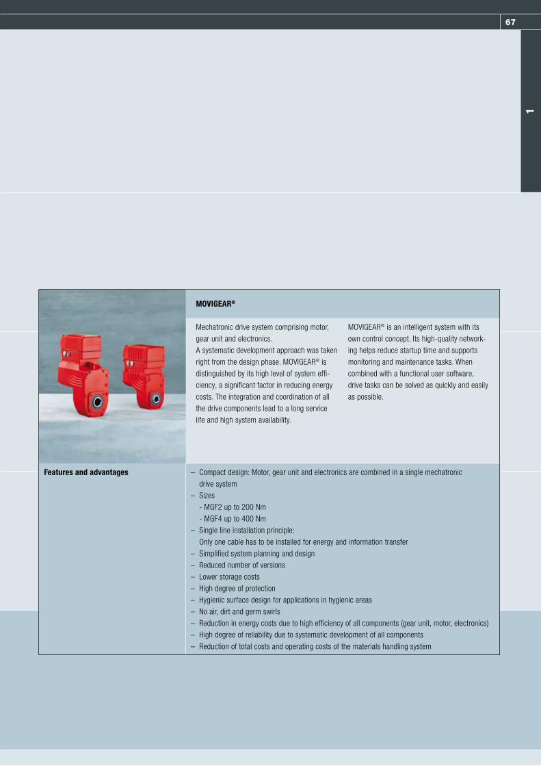
67
MOVIGEAR®
Mechatronic drive system comprising motor, gear unit and electronics.A systematic development approach was taken right from the design phase. MOVIGEAR® is distinguished by its high level of system effi-ciency, a significant factor in reducing energy costs. The integration and coordination of all the drive components lead to a long service life and high system availability.
MOVIGEAR® is an intelligent system with its own control concept. Its high-quality network-ing helps reduce startup time and supports monitoring and maintenance tasks. When combined with a functional user software, drive tasks can be solved as quickly and easily as possible.
Features and advantages – Compact design: Motor, gear unit and electronics are combined in a single mechatronic drive system
– Sizes - MGF2 up to 200 Nm - MGF4 up to 400 Nm
– Single line installation principle: Only one cable has to be installed for energy and information transfer
– Simplified system planning and design– Reduced number of versions– Lower storage costs– High degree of protection– Hygienic surface design for applications in hygienic areas– No air, dirt and germ swirls– Reduction in energy costs due to high efficiency of all components (gear unit, motor, electronics)– High degree of reliability due to systematic development of all components– Reduction of total costs and operating costs of the materials handling system
1

68 Gearmotors and frequency inverters
Netzfilter
SNI master
MOVIGEAR® SNI
MOVIGEAR® SNI
MOVIGEAR® SNI
Totally max. 10 x MOVIGEAR® SNI
EthernetMains
Controller
Sin
gle
Lin
eS
ing
le L
ine
Control cabinet level
Field level
Mains
Line filter
MOVIGEAR® SNI
Properties − Single control− Reduction in the number of components− Bus lines do not have to be routed in the field− No risk of hidden faults in the bus cabling− Reduced startup times− Shorter project runtimes / lower project costs
Applications− As a drive for applications with high breakaway and starting torques− As a drive for conveyor systems that must be operated at varying
speeds− As a drive for applications that require soft and/or defined start-up
behavior− As a group drive for easier implementation of synchronous operation
Application examples− Belt conveyors− Pallet conveyors− Roller and wheel conveyors− Screw conveyors− Container and packaging unit transports− Chain and drag-chain conveyors
Installation topology with an SNI master

69
SBus (MOVIPRO®)
MOVIGEAR®-S01
MOVIGEAR®-S01
Communication /Fieldbus Mains
Controller
Hyb
rid c
able
(mai
ns +
SB
us/C
AN
)
MOVIGEAR®-S01
MOVIGEAR® SEW system busHigh performance and fast bus communication via CAN:
Characteristics − Line wiring− Single control− Integrated communication interface− Fast communication for short cycle times− Hybrid cable for minimum installation effort− System bus controller for control cabinet or fieldbus installation with
integrated plc− High drive dynamics and performance
Application options− As drive for applications with high breakaway and starting torques− As a drive for conveyor systems that must be operated dynamically at
varying speeds − Forming intelligent function groups− Universal application due to large control range of 1:2000
Application examples− Palette conveyors− Machine-integrated conveyor belts− Feeding conveyors− Synchronized feeder conveyors− Reversing drives
Installation topology with an SEW system bus controller
1

70 Servo drive systems
CLASSIC – Servo drive systems

71
Servo drive systems from SEW-EURODRIVE excel by their dynamic performance, high flexibility, and cost-efficiency. Their design features enable optimum drive solutions for all applications that require an even balance of power and precision.
No matter whether you need a servomotor, servo gearmotor, servo electric cylinder, or servo linear drive – the product portfolio of SEW-EURODRIVE for servo applications provides versatility and dynamics.
Dynamic, versatile, and effective
2

72 Servo drive systems
MOVIAXIS® consists of axis modules, master modules, supply modules and optional
modules and a comprehensive range of accessories.
MOVIAXIS® offers:
Flexibility:– in product scalability (hardware and software)– in communication and networking options– in drive functionality and automation options– in engineering, startup, configuration and
diagnostics using MOVITOOLS® MotionStudio
Versatility:– in power range from 10 kW rated supply
power up to 187 kW peak power– in a maximum peak current of 250 A– in integrated safety technology– in robust housing design and simple
mounting– in support of all common encoder systems
Solutions:– with motion control functions from simple,
graphically selectable technology functions to powerful 32 bit control systems
– with widely applicable motor/gear unit range– with tiered motion control from simple
positioning to support of customer-specific kinematics
MOVIAXIS®

73
Master modules
Master modules are the “brain” of each axis system. Depending on the variant, the entire axis system is addressed by a non-SEW controller or by a MOVI-PLC® controller from SEW-EURODRIVE.
The MOVIAXIS® master module is available in three variants: – Fieldbus gateway with data memory– MOVI-PLC® basic motion network controller– MOVI-PLC® advanced motion network controller
Axis modules
Axis modules either communicate directly with an external controller via integrated system buses and fieldbus option cards or are controlled centrally via a master module of one of the three variants.
Features:– Maximum overload of 250 %* for maximum 1 s (max. 250 A; the overload time increases for
lower overloads)– Fast touch probe inputs– Integrated DC 24 V brake control– Comprehensive motion control and technology functions– Multi-encoder interface in the basic unit– Double 7-segment display for clear messages– Auto reload of all axis parameters when replacing the unit (in conjunction with master module)
Rated currents 8 kHz / 4 kHz PWM:– 2/2, 4/4, 8/8, 12/12, 16/16, 24/32, 32/42, 48/64, 64/85, 100/133
Supply modules
The supply modules provide the connected axes with power. They have a high overload capacity and regulate the regenerated power according to the unit variant.
Features:– 10 kW, 25 kW, 50 kW, 75 kW– Maximum overload of up to 250 % of the rated power for maximum 1s (max. 187 kW)– Minimized charging currents for line-friendly harmonic behavior and high effective current
percentage– Automatic addressing of all connected CAN axes for successful startup– With integrated braking resistor and energy storage (MXP81)– Sinusoidal regenerative power supply
* Basis 8 kHz rated current values
2

74 Servo drive systems
Perfect combination SEW-EURODRIVE servo drives operate more en-ergy-efficient than conventional drive solutions as they use high-quality permanent magnets, planetary gear units, and drive systems with energy feedback. The energy saving potential can even be further increased by combining the drives with the new components from effiDRIVE®, for example the MXR regenerative power module for MOVIAXIS®.
Individual consultationExtensive customer consultation is a central point of the modular effiDRIVE® energy saving concept for servo applications. SEW-EURODRIVE offers extensive consultation and industry exper-tise for the project planning of new systems and for retrofitting existing applications.
Advantages: – Universal modularity– Can be flexibly used and combined– Large energy-saving potential– Fully compatible with all SEW-EURODRIVE
servo components– Compact and powerful– Grid-compatible cos j = 1
Saving energy with servo drive technology

75
MXR regenerative power supply modules
The MXR regenerative power supply module has been developed for complete regeneration of braking energy. It provides a constant, con-trolled DC link voltage and drive performance regardless of variations in the supply input voltage. Power is taken from the supply system with cos j = 1 as standard. It also feeds back excess energy into the sup-ply system sinusoidally, avoiding line harmonics almost completely.
Sensitive electronic components operated on the same supply system are subject to significantly less interference. The MXR offers diverse additional service and operation features, such as information about effective power or an integrated load counter.
MXC storage modules
The optional MXC storage modules were developed for storing energy temporarily. They can be connected to all MXP supply modules. Braking energy is “moved” temporarily and utilized again during the next accel-eration process. In this way, the average amount of energy drawn from the supply system is minimized and heating of the control cabinet is
reduced or prevented. Costs for cooling and climate control measures are reduced and precious installation space is saved.
MXP81 compact supply modules
For machines with particularly compact design and fast cycle times, the compact supply modules meet demands for minimum installa-tion effort, small housing dimensions, and energy bufferen to prevent or reduce losses and heat dissipation. A braking resistor is integrated in these supply modules in addition to the storage module. Amounts of energy that exceed the storage capacity are dissipated automatically.
Operating conditions and power levels of the energy-saving modules
Very dynamic applicationswith fast cycle times
Dynamicapplication
Lowerdynamics
Lower axis output/smaller loads
MXP81 MXC / MXP81 MXR
Large servo axes/medium loads
MXC MXC / MXR
(Continuously operated)power axes/heavy loads
MXR MXR
2

76 Servo drive systems
Synchronous servomotors
CMP series
Precision, dynamics, and power – this is what the compact CMP servomotors stand for.The length of the motor has been optimized so that you can operate it in applications with very limited space. The highly dynamic servo-motors round off the CMP servomotors offered by SEW-EURODRIVE in the lower torque range.Standstill torques from 0.5 Nm to 7.1 Nm are
covered by three CMP motor sizes and a total of eight motor steps. The latest in winding and magnet technology gives the CMP servomotors a low mass moment of inertia despite their more powerful performance.
Technical data
Type Speed class [rpm] M0 [Nm] M0/VR [Nm] Mmax [Nm] Jmot [kgcm2]
CMP40S 3000 / 4500 / 6000 0.5 – 1.9 0.10
CMP40M 0.8 – 3.8 0.15
CMP50S 1.3 1.7 5.2 0.42
CMP50M 2.4 3.5 10.3 0.67
CMP50L 3.3 4.8 15.4 0.92
CMP63S 2.9 4.0 11.1 1.15
CMP63M 5.3 7.5 21.4 1.92
CMP63L 7.1 10.3 30.4 2.69
The flexibility of servomotors from SEW- EURODRIVE makes them suitable for use in all industries. These industries more and more in-clude applications in sensitive and potentially explosive atmospheres. This is the reason why synchronous CMP servomotors of the 40, 50,
and 63 series are also available in ATEX design II 3 GD. CMP servomotor series 40, 50 and 63 are suit-able for:
– II3G Ex nA II T3x– II3D EX tD A22 II T3 IP6X T150 °CX
Safe servo solutions for
explosion-proof applications
For more information on explosion-proof products from SEW-EURODRIVE, please refer to pages 26/27 and 87
For CMP71-100: You find these motors on page 24 under product announcements

77
DS/CM series
Synchronous servomotors are used in highly dynamic applications. The CM motor series, which is available in three sizes, each with three lengths, covers the 5 ... 68 Nm static torque range. Equipped with high-energy NdFeB magnets, this motor offers high over-load behavior of 400 % standstill current as standard. The CM servomotor owes its com-pact design with high power density to the magnetic circuit layout. The DS series with its three lengths covers the 1 ... 4 Nm static
torque range. The acceleration torque ofall motor sizes is three to four times the static torque. The motors feature thermal motor pro-tection and resolver feedback for motor control as standard.
Technical data
Static torque [Nm] Speed class [rpm] Mass inertia [kgcm2]
Jmot Jbmot
5 ... 68 2000 0.48 ... 189 0.83 ... 204
1 ... 68 3000
1 ... 68 4500
1 ... 21 6000
2

78 Servo drive systems
SEW-EURODRIVE offers prefabricated plug connector and encoder
cable options for all motors and gearmotors. These options are
designed in such a way that they optimally support the drive, can be
easily connected and are connected reliably with the relevant motor.
Motor type Power connector Drive electronics
CMP 40-63 Motor: SM1 MOVIDRIVE® inverter
Brakemotor: SB1
CMP 71-100 Motor: SM1, SMB MOVIDRIVE® inverter
Brakemotor: SB1, SBB
CMP 40-63 Motor: SM1 MOVIAXIS® servo inverter
Brakemotor: SB1
CMP 71-100 Motor: SM1, SMB MOVIAXIS® servo inverter
Brakemotor: SB1, SBB
Motor type Encoder connector Drive electronics
CMP 40-100 RH1M resolver MOVIDRIVE® inverter
CMP 40-63 HIPERFACE® AK0H, EK0H, AS1H, ES1H MOVIDRIVE® inverter
CMP 71-100 HIPERFACE® AK0H, EK1H, AK1H MOVIDRIVE® inverter
CMP 40-100 RH1M resolver MOVIAXIS® servo inverter
CMP 40-63 HIPERFACE® AK0H, EK0H, AS1H, ES1H MOVIAXIS® servo inverter
CMP 71-100 HIPERFACE® AK0H, EK1H, AK1H MOVIAXIS® servo inverter
Cable connections for CMP servomotors
Cables and connection options

79
Direct connection
Motor type Encoder type Encoder connection Inverter connection
DR71 – DR132 EI7S, EI76, EI72, EI71 Conductor end sleeves Conductor end sleeves
M12 plug connector MOVIDRIVE® inverter
ES7S, ES7R, AS7W, AS7Y Conductor end sleeves D-Sub plug connector
Connection cover MOVIDRIVE® inverter
DR160 – DR225 EG7S, EG7R, AG7W, AG7Y Conductor end sleeves
Connection cover
DR315 EH7S M23 plug connector
AH7Y Conductor end sleeves
Connection via intermediate sockets
Motor type Encoder type Encoder connection Adapter plug
DR71 – DR132 ES7S, ES7R, AS7W Conductor end sleeves M23 plug connector (adapter)
Connection cover
DR160 – DR225 EG7S, EG7R, AG7W, Conductor end sleeves
Connection cover
Intermediate socket
M23 plug connector (connector) Extension M23 plug connector (adapter)
Intermediate socket Inverter connection
M23 plug connector (connector) Extension D-Sub plug connectorMOVIDRIVE® inverter
Cable connections for DR series AC motors
2

80 Servo drive systems
Synchronous linear servomotors
SL2 series
The new SL2 synchronous linear motors from SEW-EURODRIVE are the perfect solution for use in highly dynamic and flexible processing machines, handling technology and pick-and place applications. Generating linear motion and force directly does not require any me-chanical transmission elements that are sub-ject to wear, such as spindles, ball bearings or toothed belts. An optimum force-density ratio is achieved by using the latest winding tech-nology and a laminated iron core.The SL2 synchronous linear motor with con-vection cooling is practically maintenance-free and offers maximum high control quality, speed and accuracy. SL2 synchronous linear motors are available in three models for speed
classes 1, 3 and 6 m/s: SL2 Basic, SL2 Ad-vance System and SL2 Power System. For lon-ger travel distances, secondaries are available in different lengths and can be easily lined up in rows. The performance of the SL2 Power System can be additionally increased by add-ing a forced cooling fan.
Technical data
Product designs Rated power range [N] Rated speed classes [m/s]
SL2 Basic 125 ... 6000 1 / 3 / 6
SL2 Advance System
SL2 Power System
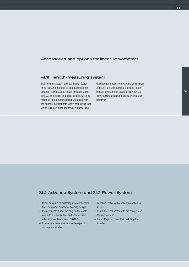
81
SL2 Advance System and SL2 Power System linear servomotors can be equipped with the optional AL1H absolute length-measuring sys-tem. AL1H consists of a linear sensor, which is attached to the motor cooling unit along with the encoder components, and a measuring tape, which is routed along the travel distance. The
AL1H length measuring system is dirtresistant and permits high speeds and accele ration. Encoder components that are ready for use allow AL1H to be assembled easily and cost effectively.
– Motor design with matching plug connectors– EMC-compliant connector housing design– Plug connectors seal the plug on the cable
end with a lamellar seal and ensure strain relief in accordance with EN 61884
– Extensive accessories for inverter-specific cable prefabrication
– Feedback cable with connection option for AL 1H
– D-sub EMC connector with pin contacts on the encoder end
– 9 and 15 pole connectors matching the inverter
Accessories and options for linear servomotors
AL1H length-measuring system
SL2 Advance System and SL2 Power System
2

82 Servo drive systems
Electric cylinders
CMS series electric cylinders
Electric cylinders of the CMS series are equipped with permanent magnet rotors and operate particularly accurately, powerfully, and quickly. Combined with drive electronics from SEW-EURODRIVE, they form economical, energy-efficient drive solutions that ensure a high level of process reliability in system
operation and are easy to integrate into existing automation systems, e.g. welding equipment and robotic systems.
Electrical data
Type CMS50S CMS63S CMS71L
Maximum torque [Nm] 5.2 11.1 31.4
Static torque [Nm] 1.3 2.9 9.5
Mechanical data
Type CMS50S CMS63S CMS71L
KGT 1) KGT 1) PGT 2) KGT 1) PGT 2)
Rated speed [nN] 3,000 rpm4,500 rpm6,000 rpm
3,000 rpm4,500 rpm
2,000 rpm 3,000 rpm4,500 rpm
Spindle pitch [mm] 5 6 5 10 6 5
Spindle diameter [mm] 16 25 20 32 32 24
Maximum permanent feed thrust 3) [N] 1,300 3,200 4,000 6,000 8,000
Peak feed thrust 4) [N] 5,300 10,500 17,000 20,000 20,000
Rated stroke [mm] 70 150 300 100 200 100 200 200 200 350 200
Maximum speed (mm/s) 375 210 450 375 500 300 200 250
1) Ball screw2) Planetary roller screw3) At a speed between 5 and 50 rpm
4) This is dependent on the maximum amplifier current and the dynamic or static load on the spindle. Contact SEW-EURODRIVE before planning the maximum force.

83SEW-EURODRIVE—Driving the world
As a leading drive technology specialist, we export reliable drive technology to every corner of the world – and we
don't stop at that. With each delivery, our customers also benefit from our range of services and fast troubleshoot-
ing solutions. More service, worldwide and 24/7, is in demand everywhere, be it Mumbai or Bruchsal. This is what
we call Drive 360° – Seeing the big picture: From system availability to problem-solving competence, from low
operating costs over energy efficiency to the complete system that handles all your tasks.
www.sew-eurodrive.com
Globalization means for us: Being close to the customer in all corners of the world.

84 Servo drive systems
Servo gear units
Planetary servo gear units
PSC series
The low backlash PSC planetary servo gear units are designed for torque classes from 30 to 305 Nm.They were designed to unite greatest possible flexibility and cost-efficiency because not every application demands machines with maximum performance. These planetary servo gear units form the basis for versatile, dynamic, and
above all cost optimized drive solutions. PSC planetary servo gear units are available in the following designs:
– PSC = B5 output, smooth output shaft– PSKC = B5 output with keyway– PSCZ = B14 output, smooth output shaft– PSKCZ = B14 output with keyway
Technical data
Size Torque class [Nm] Gear ratios1-stage [i] 2) 2-stage [i] 3)
220 30 3 / 5 / 7 / 10 15 / 21 / 25 / 30 / 35 / 49 / 50 / 70 / 100
320 65
520 160
620 320 5 / 7 / 10 25 / 35 / 49 / 50 / 70 / 100
2) Circumferential backlash: Less than 10´ for all designs3) Circumferential backlash: Less than 15´ for all designs
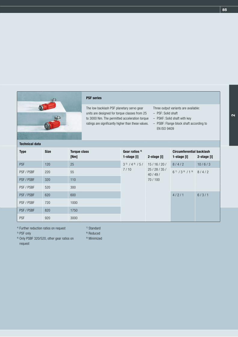
85
PSF series
The low backlash PSF planetary servo gear units are designed for torque classes from 25 to 3000 Nm. The permitted acceleration torque ratings are significantly higher than these values.
Three output variants are available:– PSF: Solid shaft– PSKF: Solid shaft with key– PSBF: Flange block shaft according to
EN ISO 9409
Technical data
Type Size Torque class [Nm]
Gear ratios 4) Circumferential backlash1-stage [i] 2-stage [i] 1-stage [i] 2-stage [i]
PSF 120 25 3 5) / 4 6) / 5 / 7 / 10
15 / 16 / 20 / 25 / 28 / 35 /40 / 49 /70 / 100
8 / 4 / 2 10 / 6 / 3
PSF / PSBF 220 55 6 7) / 3 8) / 1 9) 8 / 4 / 2
PSF / PSBF 320 110
PSF / PSBF 520 300
PSF / PSBF 620 600 4 / 2 / 1 6 / 3 / 1
PSF / PSBF 720 1000
PSF / PSBF 820 1750
PSF 920 3000
4) Further reduction ratios on request5) PSF only6) Only PSBF 320/520, other gear ratios on
request
7) Standard8) Reduced9) Minimized
2

86 Servo drive systems
BSF series
The low backlash BSF helical-bevel servo gear units are designed for torque classes from 40 to 1500 Nm. The permitted acceleration torque ratings are significantly higher than these val-ues. These right-angle servo gear units are avail - able in five output variants as standard:– BSF: Solid shaft– BSKF: Solid shaft with key– BSBF: Flange block shaft (EN ISO 9409)– BSHF: Hollow shaft with shrink disk– BSAF: Hollow shaft with keyway
(shaft mounted gear unit)
All variants come equipped with a B5 mount-ing flange, or with torque arm on swing base as an option. This means the drive units can be optimally integrated into the specific ap-plication. The input stage with helical gearing and a hypoid bevel gear output stage result in gear ratio ranges that cover those of single-stage helical-bevel and hypoid gear units as well as those of single-stage helical-worm gear units with at the same time a high level of transmission quality. The circumferential back-lash remains constantly low over the entire gear unit service life.
Technical data
Size MN [Nm] Gear ratios Circumferential backlash [’]
202 40 2-stage 3 / 4 / 6 / 8 / 10 / 15 / 20 / 25 6 12) / 3 13)
302 80 3 / 4 / 6 / 8 / 10 / 15 / 20 / 25 / 30
402 160
502 320 3 / 4 / 6 / 8 / 10 / 15 / 20 / 25 / 30 / 35
602 640 3 / 4 / 6 / 8 / 10 / 15 / 20 / 25 / 30 / 35 / 40
802 1500
12) Standard 13) Reduced

87
Options for servo gear units and servo gearmotors
Direct motor mounting Positive direct mounting (without clamping adapter) of CMP, CM and DS series SEW servomotors
Motor adapters EPH motor adapter for planetary servo gear units andEBH motor adapter for helical-bevel servo gear unitsEPH motor adapters for PS.F and PS.C planetary servo gear units, ECH motor adapters for PS.C planetary servo gear units, and EBH motor adapters for BS.F helical-bevel servo gear units.
Reduced backlash Optional for planetary servo gear units and helical-bevel servo gearunits with significantly reduced circumferential backlash
Minimized circumferential backlash Optional for planetary servo gear units withreduced circumferential backlash
*PSF/PSKF 121-522: Max. nepk 6,000 rpm.
Technical data
Ex identification Circumferential backlash classes Mamax [Nm] Mapk [Nm]
PSF* II2D c, k T3 / 150 °C Standard/ 18 – 3,000 27 – 4,200
PSKF* II2GD c, k T3 / 150 °C Reduced circumferential backlash
BSF II2D c, k T3 / 150 °C 40 – 1,310 51 – 1,910
BSAF II2GD c, k T3 / 150 °C
BSKF
BSBF
R, F, K gear units II2D c, k T4 / 120 °C 31 – 8,000 46 – 9,090
II2GD c, k T4 / 120 °C
S and W gear units II2D c, k T4 / 120 °C Standard 43 – 480 60 – 655
II2GD c, k T4 / 120 °C
For more information on explosion-proof products from SEW-EURODRIVE, please refer to pages 26/27, 38/39 and 76
2

88 Servo drive systems
System solutions with servo gearmotors
All designs and sizes of the helical, parallel shaft helical, helical-bevel and helical-worm
gear units can now also be mounted to the DS, CM and CMP synchronous servomotors
and to the CT/CV/DRL asynchronous servomotors from SEW-EURODRIVE. The /R option,
i.e. reduced circumferential backlash in conjunction with high efficiency ratings and a high
endurance gearing, provides for servotypical advantages for these gear units, such as a
high positioning accuracy.
The MOVIDRIVE® inverters, the powerful MOVIAXIS® series and their diverse options provide for functional, scalable and intelligent systems that ensure the maximum utilization of all components. The standard gear units of the 7-series excel by their efficiency, power den-
sity and wide range of variants. The synchro-nous servomotors offer precision, dynamics and torque in a particularly compact design. The combination of these gear units and motors sets global standards.
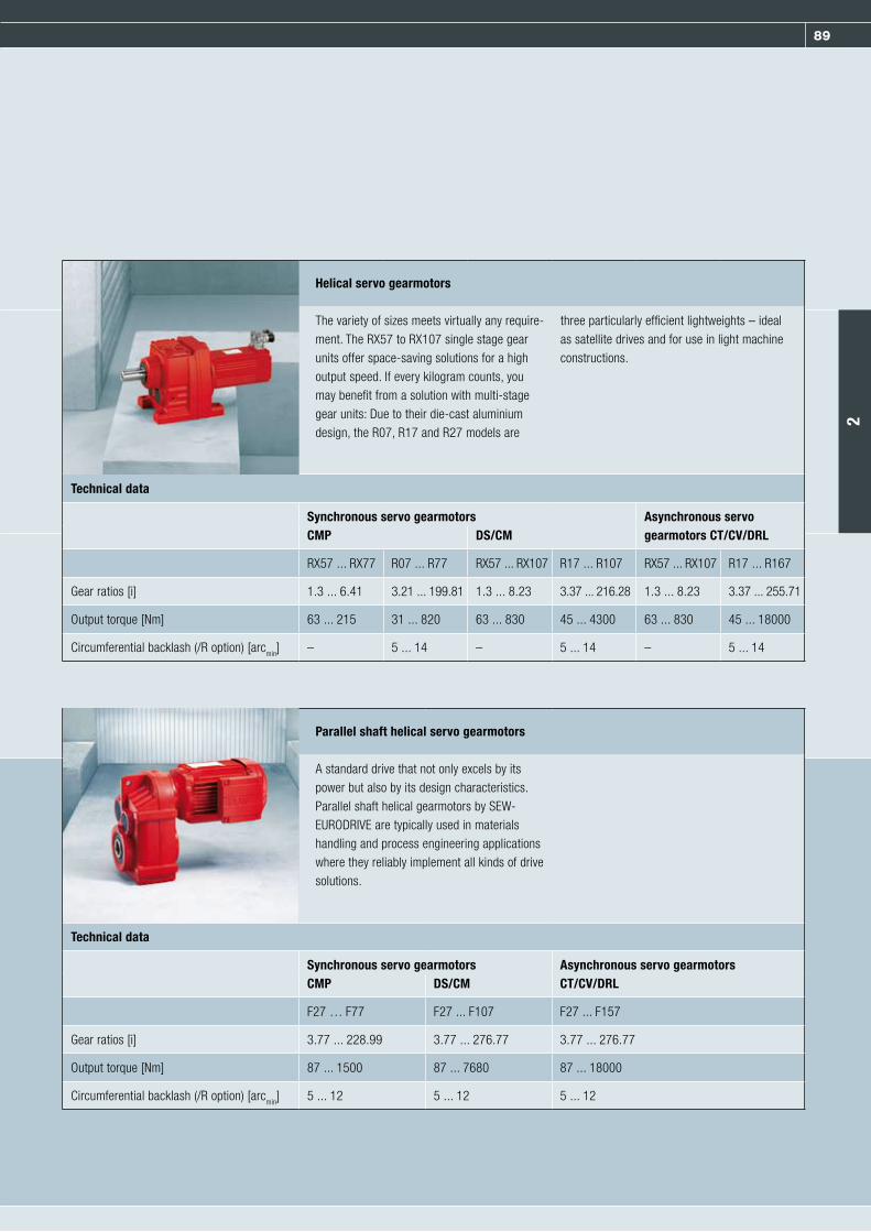
89
Helical servo gearmotors
The variety of sizes meets virtually any require-ment. The RX57 to RX107 single stage gear units offer space-saving solutions for a high output speed. If every kilogram counts, you may benefit from a solution with multi-stagegear units: Due to their die-cast aluminium design, the R07, R17 and R27 models are
three particularly efficient lightweights – ideal as satellite drives and for use in light machine constructions.
Technical data
Synchronous servo gearmotors Asynchronous servo gearmotors CT/CV/DRLCMP DS/CM
RX57 ... RX77 R07 ... R77 RX57 ... RX107 R17 ... R107 RX57 ... RX107 R17 ... R167
Gear ratios [i] 1.3 ... 6.41 3.21 ... 199.81 1.3 ... 8.23 3.37 ... 216.28 1.3 ... 8.23 3.37 ... 255.71
Output torque [Nm] 63 ... 215 31 ... 820 63 ... 830 45 ... 4300 63 ... 830 45 ... 18000
Circumferential backlash (/R option) [arcmin] – 5 ... 14 – 5 ... 14 – 5 ... 14
Parallel shaft helical servo gearmotors
A standard drive that not only excels by its power but also by its design characteristics. Parallel shaft helical gearmotors by SEW- EURODRIVE are typically used in materials handling and process engineering applicationswhere they reliably implement all kinds of drive solutions.
Technical data
Synchronous servo gearmotors Asynchronous servo gearmotorsCT/CV/DRLCMP DS/CM
F27 … F77 F27 ... F107 F27 ... F157
Gear ratios [i] 3.77 ... 228.99 3.77 ... 276.77 3.77 ... 276.77
Output torque [Nm] 87 ... 1500 87 ... 7680 87 ... 18000
Circumferential backlash (/R option) [arcmin] 5 ... 12 5 ... 12 5 ... 12
2
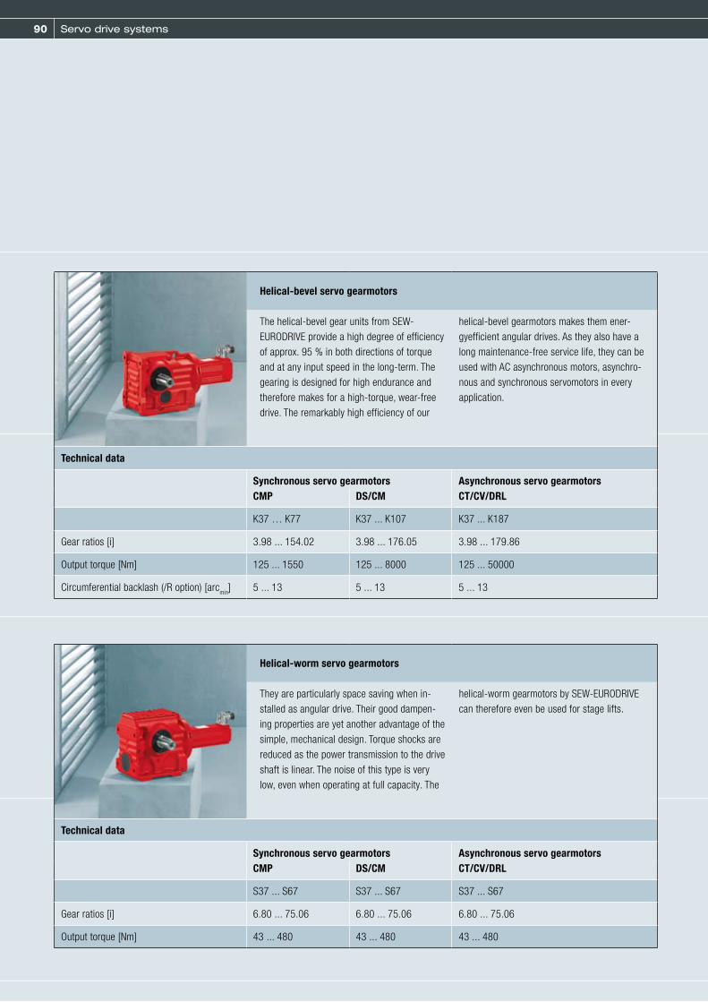
90 Servo drive systems
Helical-bevel servo gearmotors
The helical-bevel gear units from SEW- EURODRIVE provide a high degree of efficiency of approx. 95 % in both directions of torque and at any input speed in the long-term. The gearing is designed for high endurance andtherefore makes for a high-torque, wear-free drive. The remarkably high efficiency of our
helical-bevel gearmotors makes them ener-gyefficient angular drives. As they also have a long maintenance-free service life, they can beused with AC asynchronous motors, asynchro-nous and synchronous servomotors in every application.
Technical data
Synchronous servo gearmotors Asynchronous servo gearmotorsCT/CV/DRLCMP DS/CM
K37 … K77 K37 ... K107 K37 ... K187
Gear ratios [i] 3.98 ... 154.02 3.98 ... 176.05 3.98 ... 179.86
Output torque [Nm] 125 ... 1550 125 ... 8000 125 ... 50000
Circumferential backlash (/R option) [arcmin] 5 ... 13 5 ... 13 5 ... 13
Helical-worm servo gearmotors
They are particularly space saving when in-stalled as angular drive. Their good dampen-ing properties are yet another advantage of the simple, mechanical design. Torque shocks are reduced as the power transmission to the drive shaft is linear. The noise of this type is very low, even when operating at full capacity. The
helical-worm gearmotors by SEW-EURODRIVE can therefore even be used for stage lifts.
Technical data
Synchronous servo gearmotors Asynchronous servo gearmotorsCT/CV/DRLCMP DS/CM
S37 ... S67 S37 ... S67 S37 ... S67
Gear ratios [i] 6.80 ... 75.06 6.80 ... 75.06 6.80 ... 75.06
Output torque [Nm] 43 ... 480 43 ... 480 43 ... 480

91
SPIROPLAN® servo gearmotors
SPIROPLAN® servo gearmotors with directly mounted CMP synchronous servomotors oper-ate at a high level of efficiency while being low-noise at the same time. They offer a great variety of mounting positions to allow forgreatest possible flexibility for the customer. The SPIROPLAN® right-angle gear units W37/ W47 achieve great velocities at extremely low gear ratios. The wear-free gear components minimize friction losses and optimize themechanical efficiency. The gearing results in
an extremely low-noise performance. The low purchasing and life cycle costs make these drives ideally suited for simple conveyor applications. Gear unit versions:– Foot/flange-mounted designs– B5 flange– B14 flange– Solid shaft/hollow shaft– Direct mounting of servo gear unit– With adapter
Technical data
Synchronous servo gearmotors CMP
W37 ... W47
Gear ratios [i] 3.2 ... 69.05
Output torque [Nm] 70 ... 92
2

92 Decentralized drive systems
CLASSIC Drive systems for decentralized installation

93
In many industries and applications, implement-ing economical automation concepts means uti-lizing decentralized systems throughout. Long rows of control cabinets with complex wiring, expansive space requirements and long dis-tances between control cabinet and motors are too rigid and not very economical. Only the combination of flexible, versatile, economic and
target-oriented modules will provide an efficient solution. This is the reason why system opera-tors opting for decentralized drive systems from SEW-EURODRIVE are always ahead of the game, be it in the automotive, beverage and food in-dustries or in transport logistics and packaged goods handling.
All decentralized components from SEW-EURODRIVE fulfill the three most important criteria for use in automation applications: They are modular, flexible and economical.
This renders additional central switching and protection units and electronic control devices obsolete; the required control cabinet space is
reduced significantly. Costs for the previously expensive and time-consuming wiring of mo-tors, sensors and actuators are also reduced substantially. Of course, these components can be integrated in any commercial bus system. Decentralized drive systems for fast, economi-cal and flexible decentralized installation.
Decentralized implementation of economical
automation concepts
3

94 Decentralized drive systems
Decentralized drives
MOVIMOT® gearmotor with integrated frequency inverter
MOVIMOT®, the gearmotor with integrated fre-quency inverter, is a reliable combination of gearmotor and digital frequency inverter in the 0.37 to 4.0 kW power range. Despite the inte-grated frequency inverter, MOVIMOT® requires only a minimum of additional space when compared to standard gearmotors and can, of course, be supplied in all standard versions
and mounting positions, with and without a brake, for supply voltages of 380 to 500 V and 200 to 240 V.
NEW: MOVIMOT® D can be combined with the new DR motor series for different Efficiency levels as standard.
Technical data
Speed range [rpm] Voltage [V] Connection Power [kW] Torque [Nm]
280 ... 1400 (1700) 3 x 380 ... 500 0.37 ... 4.0 2.52 ... 27.3
290 ... 2900 3 x 380 ... 500 r 0.55 ... 4.0 1.81 ... 13.2
280 ... 1700 3 x 200 ... 240 0.37 ... 2.2 2.08 ... 12.4
Enclosure IP54, optional IP55, IP65 or IP66
Ambient temperature -30 °C/-20 °C to +40 °C (depending on the motor design)
Control via binary signals Entry for cw/stop, ccw/stop, setpoint switch mode isolated signal relays 2 fixed setpoints, 1 ramp for acceleration and deceleration
Control via fieldbus communication In combination with fieldbus interfaces, with and without minicontrollerPROFIBUS, PROFIsafe, INTERBUS, INTERBUS LWL, DeviceNet, CANopen, AS-Interface
Use in stand-alone applications In combination with the options:MLU..1A: Local 24 V
DC supplyMLG.1A: Local supply with 24 VDC supplyMBG11A: Speed control module for setpoint frequency specification and displayMWA21A: Setpoint converter for interfacing of analog setpoints
(0... 10 V, 0 ... 20 mA, 4 ... 20 mA) and RS-485
Use in decentralized installations In combination with field distributors:MF.../Z.3. MF.../Z.6. MF.../.../Z.7.MF.../.../Z.8.as well as the corresponding hybrid cables
Diagnostics 3-color LED signals operating status and fault status via diagnostics interface, serial interface RS485 and option MDG11A or PC
Integrated safety technology An optional SafetyDrive package enables realization of – Safety category 3 according to EN 954-1– Performance level d according to EN ISO 13849-1– SIL 2 according to IEC 61 800-5-2
Approval IEC or
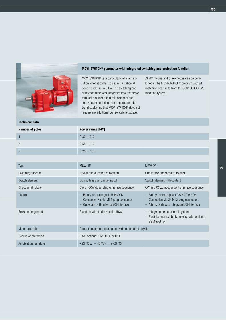
95
MOVI-SWITCH® gearmotor with integrated switching and protection function
MOVI-SWITCH® is a particularly efficient so-lution when it comes to decentralization at power levels up to 3 kW. The switching and protection functions integrated into the motorterminal box mean that this compact and sturdy gearmotor does not require any addi-tional cables, so that MOVI-SWITCH® does not require any additional control cabinet space.
All AC motors and brakemotors can be com-bined in the MOVI-SWITCH® program with all matching gear units from the SEW-EURODRIVE modular system.
Technical data
Number of poles Power range [kW]
4 0.37 ... 3.0
2 0.55 ... 3.0
6 0.25 ... 1.5
Type MSW-1E MSW-2S
Switching function On/Off one direction of rotation On/Off two directions of rotation
Switch element Contactless star bridge switch Switch element with contact
Direction of rotation CW or CCW depending on phase sequence CW and CCW, independent of phase sequence
Control – Binary control signals RUN / OK– Connection via 1x M12-plug connector– Optionally with external AS-Interface
– Binary control signals CW / CCW / OK– Connection via 2x M12-plug connectors– Alternatively with integrated AS-Interface
Brake management Standard with brake rectifier BGW – integrated brake control system– Electrical manual brake release with optional
BGM-rectifier
Motor protection Direct temperature monitoring with integrated analysis
Degree of protection IP54, optional IP55, IP65 or IP66
Ambient temperature –25 °C … + 40 °C (… + 60 °C)
3

96 Decentralized drive systems
Fieldbus interfaces, field distributor and cable systems
The variable speed MOVIMOT® drive is con-nected to the bus using terminals; additional sensors, actuators or MOVI-SWITCH® gear- motors without closed-loop control can be connected to the bus either by using terminals
or M12 plug connectors. Fault diagnosis can easily be conducted via the bus in the event of a malfunction thanks to diagnostic interfaces and LED signals.
Field distributors rationalize the connec-tion of drives with the power supply system, the 24 V
DC control voltage and the fieldbus. The units are based on the bus interfaces technol-ogy with additional connection technology for supply system distribution. Decentralized instal-
lation is made easy by installation of the field distributor close to the motor. The modular plug-in system makes for easy troubleshooting and maintenance, especially in case of a problem or service.
The hybrid cables have been developed in house and are combination cables which carry the power supply, control voltage and commu-nication strands within one cable sheath. They also guarantee optimum EMC shielding and im-pedance.The hybrid cable for connecting MOVIMOT® units to field distributors is 3 m (10 ft.) long. It combines the communications interface as well as supply and control voltage connections in one cable and is supplied as a pre-fabricated cable with plug-in connection.
MOVIMOT® drives fitted with hybrid cables can be connected to the field distributor in a mat-ter of seconds – ready to operate. For servicing, the plug can be disconnected without any dan-ger, even by personnel without technical train-ing. The drive can be replaced and the new drive re-connected quickly. The system is ideal for all applications requiring high levels of operating availability.
The fieldbus interfaces support the communication with the most frequently used field-
bus systems, PROFIBUS, INTERBUS, CANopen, DeviceNet und AS-Interface. The fieldbus
interfaces are based on a module terminal box with connecting terminals and a plug-in
fieldbus module. These interfaces can be attached directly to the drive, or they can be
mounted separately.

97
MF.. fieldbus interface MQ.. fieldbus interface
– Connection of MOVIMOT® and MOVI-SWITCH® drives to a standardized fieldbus system – Reading sensor signals – Controlling actuators via digital input and output terminals– Degree of protection: IP65– Option package:
- Degree of protection: IP66/IP67 - Stainless steel cable glands - Pressure compensation fitting - M12 metal plug for fieldbus modules with M12 plug connectors
Additionally integrated controller with the following functions:– Programmable via IPOSplus®
– Simple positioning with EI76 incremental encoder
– Integrated I/O preprocessing and timing elements
– Protocol modification
Options for MF../MQ.. fieldbus interfaces
MFG11A keypad MFG11A keypad The MFG11A keypad is plugged onto any MFZ.. connection module instead of a fieldbus interface for manual control of a MOVIMOT® drive.
DBG60B keypad The DBG60B keypad enables control of the MOVIMOT® drives in manual mode. Furthermore, the process data words can be displayed in monitor mode. The DBG60B keypad is connected directly to the diagnostic interface of the MF../MQ.. fieldbus interface.
3

98 Decentralized drive systems
MOVIFIT® decentralized drive controller
Decentralized MOVIFIT® drive controllers meet the three most important criteria of decen-
tralized drive systems: they are modular, flexible, and economical. Three unit types are
available, which combine the known advantages of decentralized installation technology
from SEW-EURODRIVE with modern, application-oriented drive and communication
functions.
Innovative connection technology allows for quick installation and startup as well as ease of diagnostic and maintenance, for example when replacing the electronics. MOVIFIT® is suited for versatile applications and supports new strate-gies for optimized system topologies. Industry-
specific unit variants, such as MOVIFIT® in HygienicPlus, are available as standard for op-eration in particular ambient conditions as they occur in the beverage industry, for example.

99
Function levels of MOVIFIT® decentralized drive controllers
The function level indicates the functions included in the software for MOVIFIT® units regarding – operation– system control – diagnostics
Classic - Simple functions – Control as fieldbus gateway via MOVILINK®
– Simple handling and functionality, can be compared with control of SEW field distributors (Z.3, Z.6 etc.)
Technology Free programming (MOVI-PLC®/MOVITOOLS® MotionStudio)
Programming takes place according to IEC 61131 (e.g. in LD, FBD, IL, ST, AS)– MOVITOOLS® MotionStudio with PLC Editor, Application Builder, etc. – Multi-stage library concept (application and program module of the MOVI-PLC® controller series)
SystemDrive-oriented conveyor functions (MOVIVISION®)
Central data storage and management– Central parameter and diagnostics system with the configurable MOVIVISION® system software – Configurable, drive-oriented conveyor functions– Simple, intuitive operation for system operators
Communication – Function levels Classic and Technology support all common bus systems: PROFIBUS, PROFINET, PROFISAFE, DeviceNet, Ethernet IP and Modbus/TCP
– Function level System supports the PROFIBUS bus system
3

100 Decentralized drive systems
MOVIFIT®-MC
– Up to three MOVIMOT® to be connected via hybrid cable– Voltage range 3 x 380 – 500 V– Integrated power distribution and line protection– Integrated communication interface– Maintenance switch– “Safe stop” function
- Safety category 3 to EN 954-1 - Stop category 0 according to EN 60204-1
– 12 digital inputs + 4 digital inputs/outputs– CAN/SBus interface for external components– Simple and fast parameter setting via DIP switches or fieldbus
MOVIFIT®-SC
– Electronic (contactless) motor starter - Connection of two motors (dual motor starter) j one direction of rotation - Connection of one motor (reversing starter) j two directions of rotation
– Power range - with connection of two motors j 2 x 0.37 to 2.2 kW - with connection of one motor j 1 x 0.37 to 4.0 kW
– Adjustable soft startup time– Voltage range 3 x 380 … 500 V– Increased safety by switching of three phases– Integrated energy distribution– Integrated brake management for SEW three-wire brakes – Optional maintenance switch– Integrated communication interface– Digital inputs/outputs
- 6 DI + 2 DI/O with Classic function level - 12 DI + 4 DI/O with function level Technology or System
– CAN/SBus interface for external components– Simple and fast parameter setting via DIP switches– Expanded parameter setting via fieldbus or diagnostics interface
MOVIFIT® : Variants and features
MOVIFIT® drive controllers have a modular structure, are available in three unit variants, and offer decentralzed installation technology
with modern, application-oriented drive and communication functions.

101
MOVIFIT®-FC
– Configurable (open-loop) frequency inverter– Power range from 0.37 to 4 kW (in two sizes)– Voltage range 3 x 380 … 500 V– Integrated energy distribution– Integrated brake management for SEW three-wire brakes and additional brake control output
for non-SEW brakes – Optional internal braking resistor (integrated in ABOX)– Optional external braking resistor– Optional maintenance switch– Integrated communication interface– User-programmable integrated controller (IEC 61131)– Digital inputs/outputs
- 6 DI + 2 DI/O with function level Classic - 12 DI + 4 DI/O with function level Technology or System for complex applications
– CAN/SBus interface for external components– “Safe stop” function
- Safety category 3 to EN 954-1 - Stop category 0 according to EN 60204-1
– Simple and fast startup via DIP switches– Expanded parameter setting via fieldbus or diagnostics interface
3
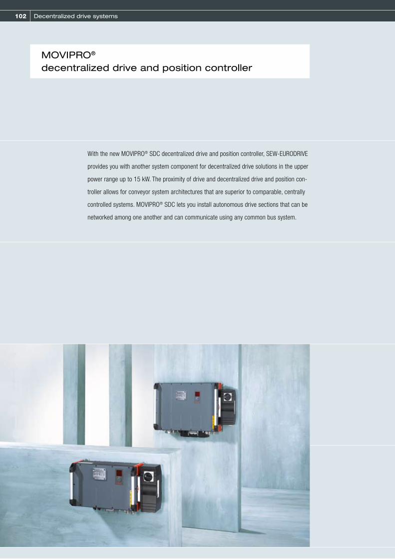
102 Decentralized drive systems
With the new MOVIPRO® SDC decentralized drive and position controller, SEW-EURODRIVE
provides you with another system component for decentralized drive solutions in the upper
power range up to 15 kW. The proximity of drive and decentralized drive and position con-
troller allows for conveyor system architectures that are superior to comparable, centrally
controlled systems. MOVIPRO® SDC lets you install autonomous drive sections that can be
networked among one another and can communicate using any common bus system.
MOVIPRO® decentralized drive and position controller
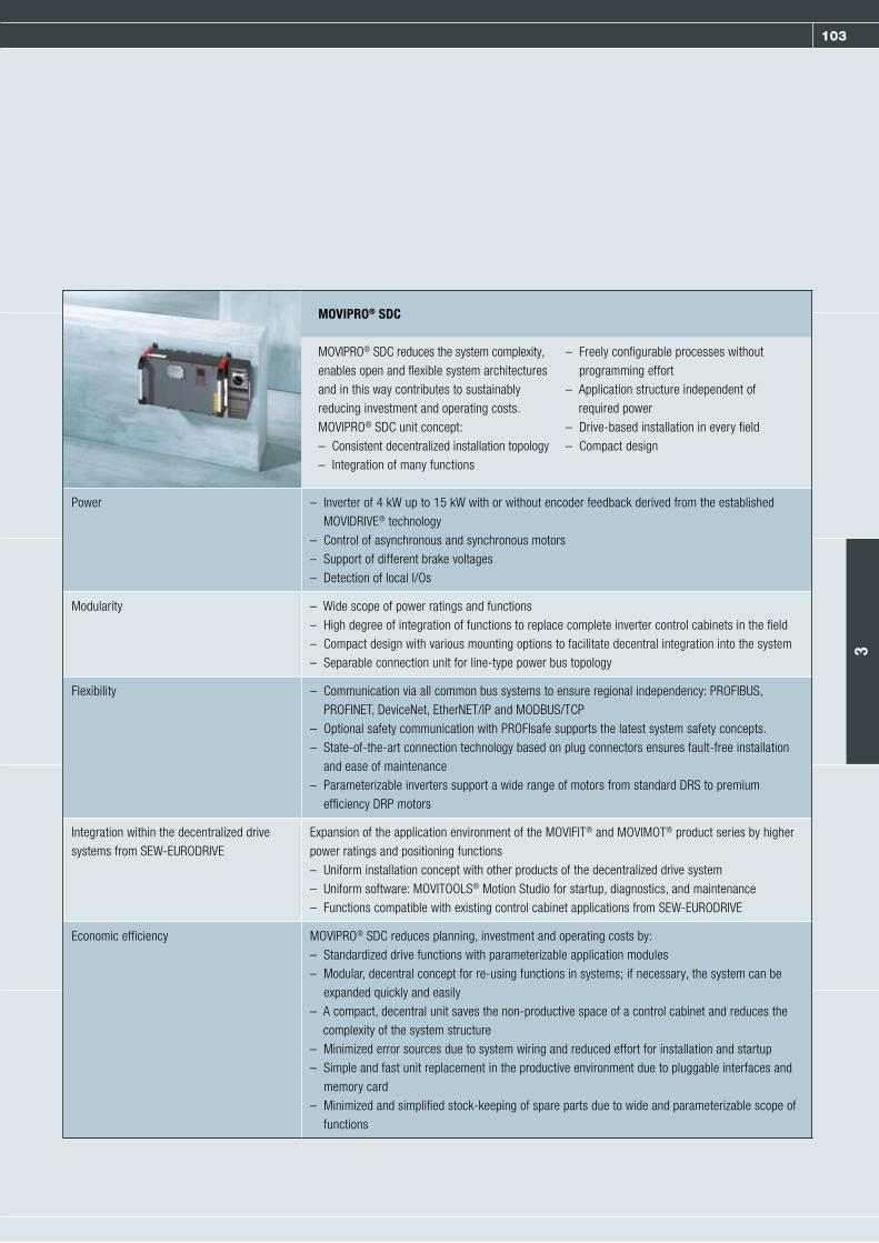
103
MOVIPRO® SDC
MOVIPRO® SDC reduces the system complexity, enables open and flexible system architectures and in this way contributes to sustainably reducing investment and operating costs. MOVIPRO® SDC unit concept:– Consistent decentralized installation topology– Integration of many functions
– Freely configurable processes without programming effort
– Application structure independent of required power
– Drive-based installation in every field – Compact design
Power – Inverter of 4 kW up to 15 kW with or without encoder feedback derived from the established MOVIDRIVE® technology
– Control of asynchronous and synchronous motors– Support of different brake voltages– Detection of local I/Os
Modularity – Wide scope of power ratings and functions – High degree of integration of functions to replace complete inverter control cabinets in the field– Compact design with various mounting options to facilitate decentral integration into the system– Separable connection unit for line-type power bus topology
Flexibility – Communication via all common bus systems to ensure regional independency: PROFIBUS, PROFINET, DeviceNet, EtherNET/IP and MODBUS/TCP
– Optional safety communication with PROFIsafe supports the latest system safety concepts.– State-of-the-art connection technology based on plug connectors ensures fault-free installation
and ease of maintenance– Parameterizable inverters support a wide range of motors from standard DRS to premium
efficiency DRP motors
Integration within the decentralized drive systems from SEW-EURODRIVE
Expansion of the application environment of the MOVIFIT® and MOVIMOT® product series by higher power ratings and positioning functions– Uniform installation concept with other products of the decentralized drive system– Uniform software: MOVITOOLS® Motion Studio for startup, diagnostics, and maintenance– Functions compatible with existing control cabinet applications from SEW-EURODRIVE
Economic efficiency MOVIPRO® SDC reduces planning, investment and operating costs by:– Standardized drive functions with parameterizable application modules– Modular, decentral concept for re-using functions in systems; if necessary, the system can be
expanded quickly and easily– A compact, decentral unit saves the non-productive space of a control cabinet and reduces the
complexity of the system structure– Minimized error sources due to system wiring and reduced effort for installation and startup– Simple and fast unit replacement in the productive environment due to pluggable interfaces and
memory card– Minimized and simplified stock-keeping of spare parts due to wide and parameterizable scope of
functions
3
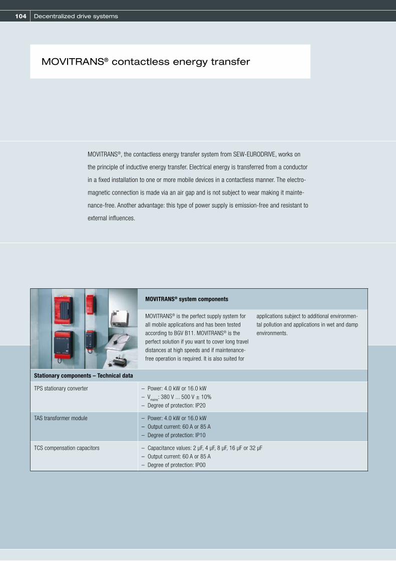
104 Decentralized drive systems
MOVITRANS® contactless energy transfer
MOVITRANS®, the contactless energy transfer system from SEW-EURODRIVE, works on
the principle of inductive energy transfer. Electrical energy is transferred from a conductor
in a fixed installation to one or more mobile devices in a contactless manner. The electro-
magnetic connection is made via an air gap and is not subject to wear making it mainte-
nance-free. Another advantage: this type of power supply is emission-free and resistant to
external influences.
MOVITRANS® system components
MOVITRANS® is the perfect supply system for all mobile applications and has been tested according to BGV B11. MOVITRANS® is the perfect solution if you want to cover long travel distances at high speeds and if maintenance-free operation is required. It is also suited for
applications subject to additional environmen-tal pollution and applications in wet and damp environments.
Stationary components – Technical data
TPS stationary converter – Power: 4.0 kW or 16.0 kW– V
mains: 380 V ... 500 V ± 10%– Degree of protection: IP20
TAS transformer module – Power: 4.0 kW or 16.0 kW– Output current: 60 A or 85 A– Degree of protection: IP10
TCS compensation capacitors – Capacitance values: 2 μF, 4 μF, 8 μF, 16 μF or 32 μF– Output current: 60 A or 85 A– Degree of protection: IP00
105
Mobile components – Technical data
TPM12B mobile converter – Rated output power - when connecting 4x THM10C: max. 3.6 kW - when connecting 2x THM10E: max. 3.0 kW
– Output voltage: DC 500 V– Additional output voltage: 24 V, max. 2 A– Degree of protection: IP65
THM10E pick-up – Power: 1.5 kW– Degree of protection: IP65
THM10C pick-up – Rated power: 0.8 kW– Peak power: 0.9 kW– Degree of protection: IP65
TVS connection distributor – Degree of protection: IP65– Output current: 60 A or 85 A
TCS compensation box – Degree of protection: IP65– Output current: 60 A or 85 A– Compensates a distance of 25 to 30 m
3

106 Decentralized drive systems
MOVITRANS® with flat pick-up
(THM10E)

107
MOVITRANS® with U-shaped
pick-up (THM10C)
TISInstallation components for line cable support
3

108 Industrial gear units
CLASSIC – Industrial gear units

109
SEW-EURODRIVE offers the right industrial gearunits when you need especially large torqueratings to carry out especially large movements.The modular concept will once again provideoptimum adaptation of industrial gear units tomeet a wide range of different applications.SEW-EURODRIVE is your competent partner for
all areas, from process planning, through projectplanning all the way to startup. These servicesare supported by our renowned, worldwideservice network in order to guarentee thereliable completion of all process stages.
SEW-EURODRIVE offers five series of industrialgear units with impressive data and perfor-mance. Output torques up to 700 kNm are no problem. Whether series or customized gear units, SEW-EURODRIVE industrial gear units can
handle all types of applications in such industries as systems engineering, mining, shipbuilding and the energy, timber, mineral and processing industries.
Innovative drive solutions
for all industries and applications
All services made by SEW-EURODRIVE
Power for every application
4

110 Industrial gear units
X series
Robust and universal gear unit series whichcan be optimally adjusted to the task due to finely stepped torque ratings. The universal modular system concept sets new standards with respect to availability and offers a broad range of application options, e.g. for materials
handling systems, ball mills, and agitators. Application gear units, such as for bucket elevators, complete the range.
Technical data
Gear unit version Stages Reduction ratios Rated torque MN2 [kNm]
Helical gear unit X.F..: 2, 3 and 4 stages 6 ... 400 58 ... 475
Bevel-helical gear unit X.K..: 2, 3 and 4 stages 6 ... 400 58 ... 475
Bevel-helical gear unit X.T..: 3 and 4 stages 12 ... 400 58 ... 475
Baureihe MC
MC series industrial gear units are particularlycompact helical and bevel-helical gear units.The 6 sizes available in the MC series coverthe 6 to 48 kNm torque range. Their parallelshaft design offers plenty of flexibility insystem design and requires remarkably little
space. MC gear units can be used in applica-tions such as materials handling, transportingheavy loads, mixing, crane drives and shred-ders. Based on this series, a version with increased bearing distance and reinforced output shaft is available.
Technical data
Gear unit version Stages Reduction ratios Rated torque MN2 [kNm]
Helical gear unit MC.P..: 2 and 3 stages 7.1 ... 112 6 ... 48
Bevel-helical gear unit MC.R..: 2 and 3 stages 7.1 ... 112 6 ... 48
ML series
ML series helical and bevel-helical gear unitsare the ideal platform for customized applica-tions with a variety of options for connecting awide range of modules. The flexibility and vari-ability of these gear units are hard to beat. An increased center distance is available, for
example for hoist applications. ML series gear units are available in 5 sizes, covering the 180 to 680 kNm torque range. ML gear units can be used in applications such as mining, crane construction and the chemical industry.
Technical data
Gear unit version Stages Reduction ratios Rated torque MN2 [kNm]
Helical gear unit ML.P..: 2, 3 and 4 stages 6 ... 315 180 ... 680
Bevel-helical gear unit ML.R..: 3, 4 and 5 stages 14 ... 1250 180 ... 680
Helical and bevel-helical gear units

111
P.MC.. series
This series is characterized by the mainte-nance-free and fully oil-covered bearings,combined with the high power density of theplanetary output stages. They are mainly usedfor high gear ratios and low output speeds.Individual optional features, such as special
sealing systems and lubricants, torque armsand swing bases complete the range, which ismainly used for slat conveyors, bucket-wheelreclaimers and jibs.
Technical data
Gear unit version Stages Reduction ratios Rated torque MN2 [kNm]
Stirnrad-/Kegelstirnrad-Planetengetriebe P1.MC..: 3 and 4 stages 31.5 ... 500 24 ... 185
Stirnrad-/Kegelstirnrad-Planetengetriebe P2.MC..: 4 and 5 stages 140 ... 4000 69 ... 359
Planetary gear units
P series
Up to now, it was almost impossible to orderplanetary gearmotors in this power class froma catalog. Our P series products are a signifi-cant step closer to achieving this ideal situa-tion. The gearmotor is mounted directly in front of the planetary gear unit. Couplings, interme-diate flanges and adapter flanges that take up space and increase costs are a thing of the
past. P series units are available in 9 sizes, covering the 24 to 359 kNm torque range. P gearmotors can be used anywhere you need to move heavy weights at a low speed.
Technical data
Gear unit version Stages Reduction ratios Rated torque MN2 [kNm]
Helical planetary gear unit (motor) P.RF..: 4 and 5 stages 100 ... 4000 24 ... 359
Bevel-helical planetary gear unit (motor) P.KF..: 5 stages 140 ... 4000 24 ... 359
4

112 Industrial gear units
Explosion-proof industrial gear units
ValidityThe new directive 94/9/EC or ATEX 95 specifiesnew regulations for explosion protection in alltypes of devices for the European market.This directive is therefore also valid for industrialgear units of the MC series and planetarygear units. As of July 1, 2003, the directive94/9/EC has been applying without restrictionsto the use of industrial gear units of the X, MCseries and planetary gearmotors within theEuropean Union. Other European countries,such as Switzerland, have fallen in with thisregulation since.
Special measures are required for the operationof systems and machinery in areas with poten-tially explosive air/gas or air/dust mixtures. Ifmixture formation cannot be prevented, speciallyprotected gear units have to be used. Applicablestandards and regulations govern the use ofequipment within existing hazard zones. Theyalso regulate the quality requirements that haveto be met by the drive manufacturer.
Explosion-proof industrial gear units of the MC,
X series and P, P.MC.. planetary gear units.
Explosion protection according to ATEX

113
The explosion-proof industrial gear units of theX, MC series and the planetary gear units ofSEW-EURODRIVE meet the constructionrequirements for group II, category 2G or 3G(potentially explosive gas atmospheres) and 2D
or 3D (potentially explosive dust atmospheres).The gear units are suitable for use in zones 1and 21 or zones 2 and 22.
4
Seeing the big picture.
Seeing the big picture.
Seeing the big picture.
Seeing the big picture.
From the first idea to the running system, and beyond.
SEW-EURODRIVE—Driving the world
For every motion in your machines and systems and for every industry: As a leading drive technology specialist, we always supply the right drive. This includes not only gear units, motors or drive electronics, but also the matching controller and a comprehensive service portfolio. This is what we call Drive 360° – Seeing the big picture: From system availability to problem-solving competence, from low operating costs over energy efficiency to the complete system that handles all your tasks.
www.sew-eurodrive.com

SEW-EURODRIVE not only offers powerful and flexible drive technology, VARIOLUTION® pack-
ages and MAXOLUTION® system solutions but also the matching system accessories, such as
The result are individual application solutions in coordination with system designers and system operators that ensure the required functionality and efficiency in all project phases: from project
planning through startup all the way up to oper-ation and production reliability as well as main-tenance and service.
SEW-EURODRIVE –
your partner for drive engineering
– controllers– Remote maintenance– operator terminals– project planning tools and
– startup software – Drive Benefits – CDS® Complete Drive Service– And many more
Other system components and services
Other system components and services
5
115Other system components and services

116 Other system components and services
MOVI-PLC® controllers
Designing functional and efficient drive solutions requires a high degree of flexibility of all
components involved, that is, drives and drive electronics as well as suitable technology.
MOVI-PLC® controllers
MOVI-PLC® is a programmable logic controller for inverters that offers flexible solutions for user-friendly and powerful automation of drive applications. Logic processing and sequence control are realized using programming languages in accordance with IEC 61131-3.
Universal MOVI-PLC® can easily be integrated into any drive solution: as an option card in MOVIDRIVE® B inverters or MOVITRAC® B frequency inverters, as well as in the MOVIAXIS® multi-axis inverters, in the decentralized MOVIFIT® drive control or as a compact control on a DIN rail. It is also considered a universal solution because all SEW-EURODRIVE inverters can be connected via the system bus. Furthermore, only one tool is required for the engineering of both the MOVI-PLC® and the inverters.
Scalable MOVI-PLC® is scalable as it is available in two power classes:– MOVI-PLC® basic for the medium power range controls up to 12 axes– MOVI-PLC® advanced for the higher power range allows for controlling up to 64 axes.Both classes are available with various technology levels: Level T0 with single-axis functions, T1 for technology functions, and T2 for application solutions and multi-axis interpolation of complex kinematics.
The connection of the drives via a CAN or EtherCat-based system bus, as well as via the interface to the higher-level control based on classic fieldbuses or ETHERNET.
Powerful A broad variety of function blocks provides the user with convenient access to the entire drive functionality, whereas the programming to IEC 61131 allows for simple handling. Thus, users are able to quickly implement complex drive tasks. The connection of the inverters via the fast, clock-synchronous system bus allows for reducing response times and thus enhancing the performance of the drive system, particularly when coordinating multiple axes.

117
Keeping the access to comprehensive drive func-
tionality as simple as possible is also critical for the
implementation. MOVI-PLC® provides drive functionality
in the form of parameterizable function blocks that
can be programmed conveniently to IEC 61131. These
blocks are adapted to the drive electronics and provide
scalable functionalities – simple single-axis functions,
universal program modules, or application solutions for
multiple axes. The integrated standard blocks of a PLC
additionally provide full Logic Control.
5
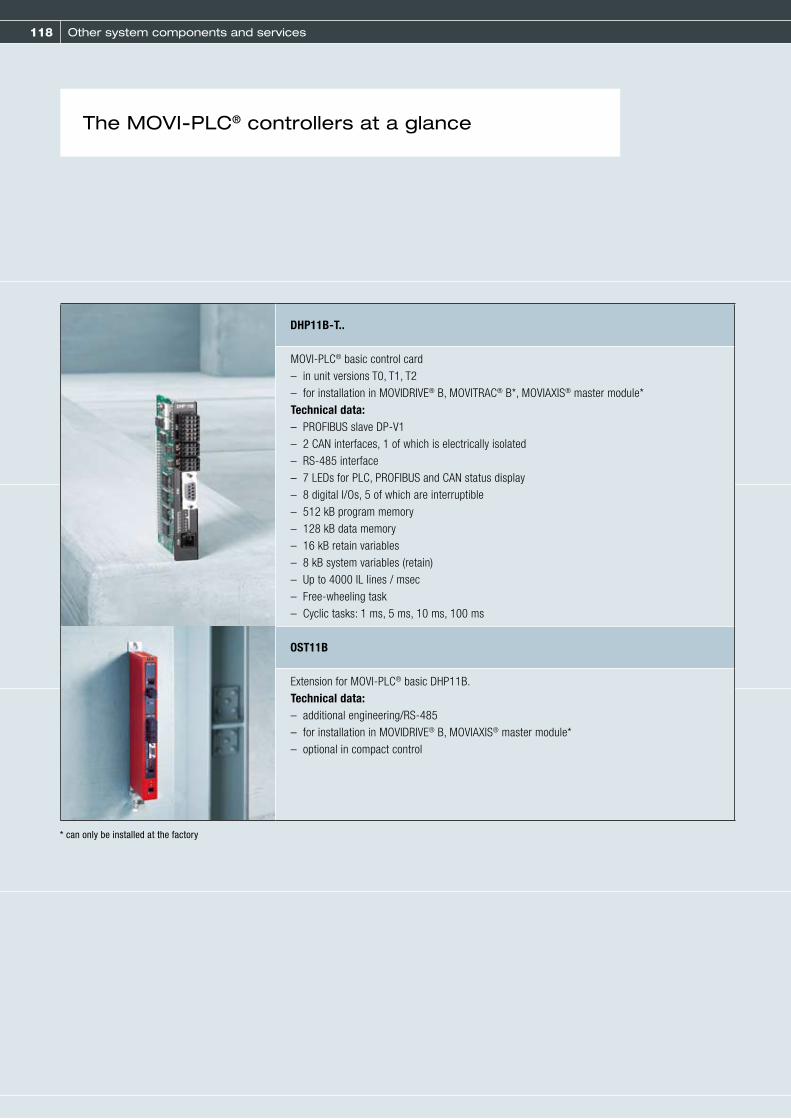
118 Other system components and services
DHP11B-T..
MOVI-PLC® basic control card– in unit versions T0, T1, T2– for installation in MOVIDRIVE® B, MOVITRAC® B*, MOVIAXIS® master module*Technical data:– PROFIBUS slave DP-V1– 2 CAN interfaces, 1 of which is electrically isolated– RS-485 interface– 7 LEDs for PLC, PROFIBUS and CAN status display– 8 digital I/Os, 5 of which are interruptible– 512 kB program memory– 128 kB data memory– 16 kB retain variables– 8 kB system variables (retain)– Up to 4000 IL lines / msec– Free-wheeling task– Cyclic tasks: 1 ms, 5 ms, 10 ms, 100 ms
OST11B
Extension for MOVI-PLC® basic DHP11B.Technical data:– additional engineering/RS-485– for installation in MOVIDRIVE® B, MOVIAXIS® master module*– optional in compact control
The MOVI-PLC® controllers at a glance
* can only be installed at the factory

119
DHx41B
MOVI-PLC® advanced control card– DHE41B with ETHERNET interface– DHF41B with additional PROFIBUS and DeviceNet slave interface– DHR41B additionally with PROFINET / Ethernet IP / Modbus TCP/IP-Slave interface– for installation in MOVIDRIVE® B, MOVITRAC® B*, MOVIAXIS® master module*Technical data:– 2 x ETHERNET (10/100 BaseT)– 2 x CAN interfaces, 1 of which is electrically isolated– 2x RS-485– USB– PROFIBUS slave DP-V1, DeviceNet slave (DHF41B)– 8 digital I/O – Status display for PLC and fieldbus– 8 MB program memory– 4 MB data memory– 32 kB retain variables– 8 kB system variables (retain)– Up to 4000 IL lines/msec– free-wheeling task, 5 cyclic tasks (1 ms ... 10000 ms)– PC-readable memory card for firmware and application program
OMH41B-T..
Memory cards for MOVI-PLC® advanced– with technology activation T0 ... T10
DH../../UOH..
MOVI-PLC® compact controls– DHP11B-Tx/UOH11B– DHP11B-Tx/OST11B/UOH21B– DHE41B/UOH11B– DHF41B/UOH21B*
MT..
MOVIFIT® function level “Technology”– with integrated MOVI-PLC® basic– for decentralizedm field installation
* can only be installed at the factory, DHF41B not in MOVITRAC® B
* product announcement
5
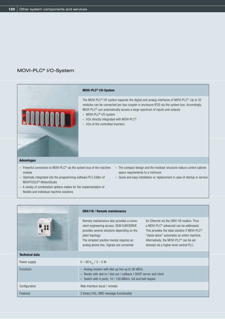
120 Other system components and services
MOVI-PLC® I/O-System
The MOVI-PLC® I/O system expands the digital and analog interfaces of MOVI-PLC®. Up to 32 modules can be connected per bus coupler in enclosure IP20 via the system bus. Accordingly, MOVI-PLC® can automatically access a large spectrum of inputs and outputs:– MOVI-PLC® I/O system– I/Os directly integrated with MOVI-PLC® – I/Os of the controlled inverters
Advantages
– Powerful connection to MOVI-PLC® via the system bus of the machine module
– Optimally integrated into the programming software PLC Editor of MOVITOOLS® MotionStudio
– A variety of combination options makes for the implementation of flexible and individual machine solutions
– The compact design and the modular structure reduce control cabinet space requirements to a minimum
– Quick and easy installation or replacement in case of startup or service
MOVI-PLC® I/O-System
ORA11B / Remote maintenance
Remote maintenance also provides a conve-nient engineering access. SEW-EURODRIVE provides several solutions depending on the plant topology:The simplest solution merely requires an analog phone line. Signals are converted
for Ethernet via the ORA11B modem. Thus a MOVI-PLC® advanced can be addressed. This provides the ideal solution if MOVI-PLC® “stand-alone” automates an entire machine. Alternatively, the MOVI-PLC® can be ad-dressed via a higher-level central PLC.
Technical data
Power supply 0 – 60 VDC / 3 – 5 W
Functions – Analog modem with dial-up line up to 56 kBit/s– Router with dial-in / dial-out / callback / DHCP server and client– Switch with 4 ports, 10 / 100 MBit/s, full and half-duplex
Configuration Web interface (local / remote)
Features 2 binary I/Os, SMS message functionality

121
Programming or parameterization
Motion control with MOVI-PLC® provides three options that will provide functional solutions
quickly and easily, irrespective of the complexity of the individual task or the programming
skills of the user.
Function blocks: Versatile combinations and flexible applications
The direct access to the blocks that allow for a certain drive function provide the highest level of flexibility. They are clearly arranged in librar-ies according to their functionality and the re-spective type of inverter. With some experience,
the user can flexibly combine these function blocks to form an optimal program.
Program modules: Optimized connection and efficient use
The program modules comprise bundled com-prehensive drive functions. These can be simple functions like positioning, referencing or speed control, technology functions for controlling a cam or a synchronous operation, or functions for multi-axis interpolations of kinematics. Once these program modules have been integrated, the user merely has to concentrate on program-
ming the most important processes of the re-spective application. The program modules pro-vide the entire drive functionality via an interface. Thus, program modules are ideal for PLC pro-grammers that intend to reduce the program-ming effort of the drive functionality. möchten.
Application modules: Individual preprogramming and immediate executability
The application modules comprise function blocks that, in turn, contain drive functions for certain applications. The user can use function blocks directly as executable pro-grams by using simple parameterization
without having to deal with complex pro-gramming. The MOVI-PLC® can be operated directly via a defined process data interface.
5

122 Other system components and services
Functional safety technology
Inverters with integrated safety technology/control cabinet Functionality
MOVITRAC® B frequency inverters – Safe disconnection (integrated in the unit)– Safe communication– - DFS11B PROFIsafe / PROFIBUS with output for safe disconnection of
MOVITRAC®
– - DFS12B PROFIsafe / PROFIBUS with CAN connection for DCS21B
MOVIDRIVE® B inverters – Safe disconnection (integrated in the unit)– Safe communication– - DFS11B PROFIsafe / PROFIBUS with output for safe disconnection of
MOVIDRIVE®
– - DFS12B PROFIsafe / PROFIBUS with CAN connection for DCS21B– - DFS21B PROFIsafe / PROFINET with output for safe disconnection of
MOVIDRIVE®
– - DFS22B PROFIsafe / PROFINET with CAN connection for DCS21B– - DCS21B safety monitor with speed and position monitoring and
PROFIsafe connection– - DCS31B safety monitor with speed and position monitoring and
binary control
Avoiding industrial accidents while maintaining trouble-free and economical system operation
can be implemented flexibly and individually using integrated and modular safety technology
from SEW-EURODRIVE. Compliance with EN 954-1 and EN ISO 13849-1, intended to minimize
the risk posed to people by technical equipment, allows for installating system control that
monitors the production process instead of switching it off. The control systems applied must
satisfy the relevant requirements regarding safety and performance level.

123
Decentralized installation Functionality
MOVIMOT® gearmotors with integrated frequency inverter – Safe disconnection (integrated in the unit)– Safe communication (as option with MOVIFIT®)
MOVIFIT® decentralized drive control:– FC series: Open-loop frequency inverter– MC series: Up to three MOVIMOT® units can be connected via
hybrid cable
– Safe disconnection (integrated in the unit)– Safe communication with safety option S11, via PROFIsafe/PROFIBUS
or PROFIsafe/PROFINET
Field distributors – Safe disconnection (integrated in the unit)– Safe communication with MQS22F/32F via PROFIsafe/PROFIBUS
Servo Functionality
MOVIAXIS® multi-axis servo inverters – Safe disconnection (integrated in the unit)– Movement and positioning monitoring
(as option with modular safety technology UCSxxB)
Modular and universal safety technology Functionality
MOVISAFE® UCSxxB – Multi-axis capable– Speed, velocity, standstill, direction and emergency stop monitoring– Safe position, safe target travel, safe travel range– Certified to SIL3 (IEC 61508 and IEC 62061)– For operation up to category 4/PL e (EN ISO 13849-1)
– MOVISAFE® UCS10B, safety modules with logic operation– MOVISAFE® UCS11B, safety modules, monitoring with 1 encoder– MOVISAFE® UCS12B, safety modules, monitoring with 2 encoders
– 14 digital inputs– 2 clock outputs– 2 relay outputs– 4 electronics outputs (2 of them safe)– 2 signal outputs
MOVISAFE® UCS23Bdigital expansion modules
Expansion for the basic modules– Up to 2 modules can be expanded– 14 digital inputs– 10 configurable inputs / outputs– 2 clock outputs
MOVISAFE® UCS25Bdiagnostic modules
Expansion for the basic modules– Diagnostics via configurable CAN interface
Electromechanics and mechanics Functionality
Safety-oriented BST brake modules Safe brake control, meets the requirements of – EN 954-1; cat. 3– EN ISO 13849-11; cat. 3, PL d
BMG.T double disk brakes Specifically for use in theaters; meets the requirements of – DIN 56950 – EN 954-1; cat. 3– EN ISO 13849-1; PL d– BGV C1
5

124 Other system components and services
Safety fieldbus: PROFIsafe
Power supply
I am
PR
OFIsa
fe
B U S
P R O F I
Centralized installation via PROFIsafe
The safe stop function to EN 954-1 can be activated via PROFIsafe for MOVIDRIVE® B inverters and MOVITRAC® B frequency inverters.
The figure shows the implementation of a PROFIsafe installation with MOVIDRIVE® B inverter with integrated disconnection and standard motors or gearmotors.
Process data and safety related information will be transmitted via one single medium. The costs for installation of a separate, safety-related fieldbus will be eliminated.
– DFS11B interface is required for connecting MOVIDRIVE® B / MOVITRAC® B: PROFIsafe to PROFIBUS– DFS21B interface is required for connecting MOVIDRIVE® B / MOVITRAC® B: PROFIsafe to PROFINET– Cost savings– This interface evaluates the safety-related protocol and offers a safety-related output to switch an individual MOVIDRIVE® / MOVITRAC® B or a
group of MOVIDRIVE® / MOVITRAC® B units to safe stop.4

125
MOVIMOT® – Decentralized installation via PROFIsafe
MOVIMOT® gearmotors with integrated frequency inverters can be controlled using PROFIsafe in conjunction with type MQS../Z.6F field distributors. Field distributors with an integrated type MQS../Z.7F or MQS../Z.8F MOVIMOT® inverter are also equipped with a PROFIsafe interface. This provides the safe stop function. In addition, the safety-oriented MQS.. field distributor offers two additional safety-oriented inputs for the connection of emergency stop relays.
The figure shows an installation that is comprehensively decentralized through to the control level via PROFIsafe, for use in safety applications compliant with EN 954-1, category 3.
MOVIFIT® – Decentralized installation via PROFIsafe
The MOVIFIT® drive control can also be controlled via PROFIsafe by connecting MOVIFIT® MC or FC to the PROFIsafe option S11. This is the safe stop function. The PROFIsafe option S11 offers four additional safety-related inputs for connecting safe sensors and two safety-related outputs.
The figure shows the implementation of a uniform decentralized installation right through to the control level via PROFIsafe, for use in safety applications according to EN 954-1, category 3.
5

126 Other system components and services
Diagnostic units
DUV10A Diagnostic Unit VibrationDrive diagnostics using vibration analysis for preventive maintenance
The DUV10A diagnostic unit from SEW-EURODRIVE is the perfect sensor for simple and reliable monitoring of antifriction bearings. The DUV10A diagnostic unit mea-sures the structure-borne noise and uses this value to calculate the frequency spectrum. The unit uses this frequency spectrum to con-stantly evaluate the condition of the antifriction
bearings. The structure-born noise sensor and evaluation electronics are fully integrated in the diagnostic unit.
DUV10A diagnostic unit overview:
– Maintenance intervals can be planned according to the application– Data is decentrally recorded, processed, and evaluated– Signs of wear on anti-friction bearings are detected at an early stage– The condition of the bearings is simple to detect and read:
The colors green, yellow, and red indicate the condition of the bearings– Monitoring options: Read values directly from the sensor or visualize them externally via switch outputs (DUV10A can be linked to bus systems)– Parameters set via RS-232 interface– System operators can set parameters as required– Up to 5 bearing positions can be monitored with one sensor– Alternative: Diagnosis of 20 single frequencies (e.g. tooth meshing frequency, imbalance)– Level monitor that monitors the entire vibration spectrum
Preventive maintenance is becoming an increasingly important feature for many systems
from an economic point of view. The diagnostic units from SEW-EURODRIVE offer perfect
assistance: They help to prevent downtimes and increase system availability.

127
DUB10A diagnostic unitBrake diagnostics with function and wear analysis
The DUB10A (Diagnostic Unit Brake) diagnostic unit from SEW-EURODRIVE is the ideal sensor for monitoring the wear and functionality of the brake. The voltage-dependent signal can be evaluated by an SEW-EURODRIVE frequency inverter or a higher-level controller.
Two sensors allow you to monitor proper brake functioning and lining wear simultaneously and reliably.
DUB10A diagnostic unit overview:
– Maintenance intervals can be planned individually according to wear– Brake lining wear can be detected in good time– Reliable brake function monitoring– Easily processed voltage-dependent output signal– Quick diagnosis of the condition of the brake– Can be used in damp conditions up to IP66– Actuators made of stainless steel– Self-cleaning contacts inside the sensor– Snap switch mechanism: Flexible tongue made of beryllium-copper with self-cleaning contacts– Housing material: PA6T/X with fiberglass reinforcement– Actuator material: Stainless steel
DUO10A Diagnostic Oil Aging Gear unit oil diagnostics using thermal analysis for preventive maintenance
The DUO10A diagnostic unit from SEW-EURODRIVE is the perfect sensor to determine the remaining service life of gear unit oil and indicate the right time for an oil change. A thermal sensor installed in the gear unit measures the oil temperature and for-wards this information to an evaluation unit, which then calculates the time remaining until the next oil change for the specified oil type.
The diagnostic unit takes the oxidation charac-teristics under thermal stress of the different oils into account.
DUO10A diagnostic unit overview:
– Reduces oil costs– Optimally utilizes oil service life– Maintenance intervals can be planned according to the application– Parameter setting and startup can be performed directly on the diagnostic unit (without PC)– Time until next oil change can be detected and read off easily– Monitoring options: The remaining service life and status messages can be read on the diagnostic unit or externally visualized via switch outputs
(DUO10A can be linked to bus systems)– Monitoring for 5 different types of oil
5

128 Other system components and services
DOP operator terminals for visualization and diagnostics
Operator terminals are programmed using the HMI Builder operating software. This software operates on a WYSIWYG basis. During program-ming the user can see how the operators will see the visualization later. The HMI Builder pro-
vides an object library with a large selection of static and dynamic objects. These objects are represented by simple and illustrative symbols. Users simply select and edit objects to create their own personalized screen display.
The DOP (Drive Operator Panel) series operator terminals meet these requirements and provide additional and new functions, such as recipe management, dual driver function, pass-through mode, or integrated web server. Operator ter-minals let you implement optimal visualization and operation of the system in a simple, reliable manner at any time and any place.
They make for constant optimization of the pro-duction process and let you adjust individual parameters immediately, such as speed, target positions, stop marks, and ramps. These are op-timal requirements for the economic efficiency and reliability of the plant.
HMI Builder
Modern drive inverters and controllers are increasingly taking on control functions. In
particular, drive tasks, such as positioning, synchronous operation and the coordinated
movement of several drives in relation to one another, are being performed with high levels
of accuracy. As more and more functions are integrated, the demands on operation,
visualization and diagnostics also increase.
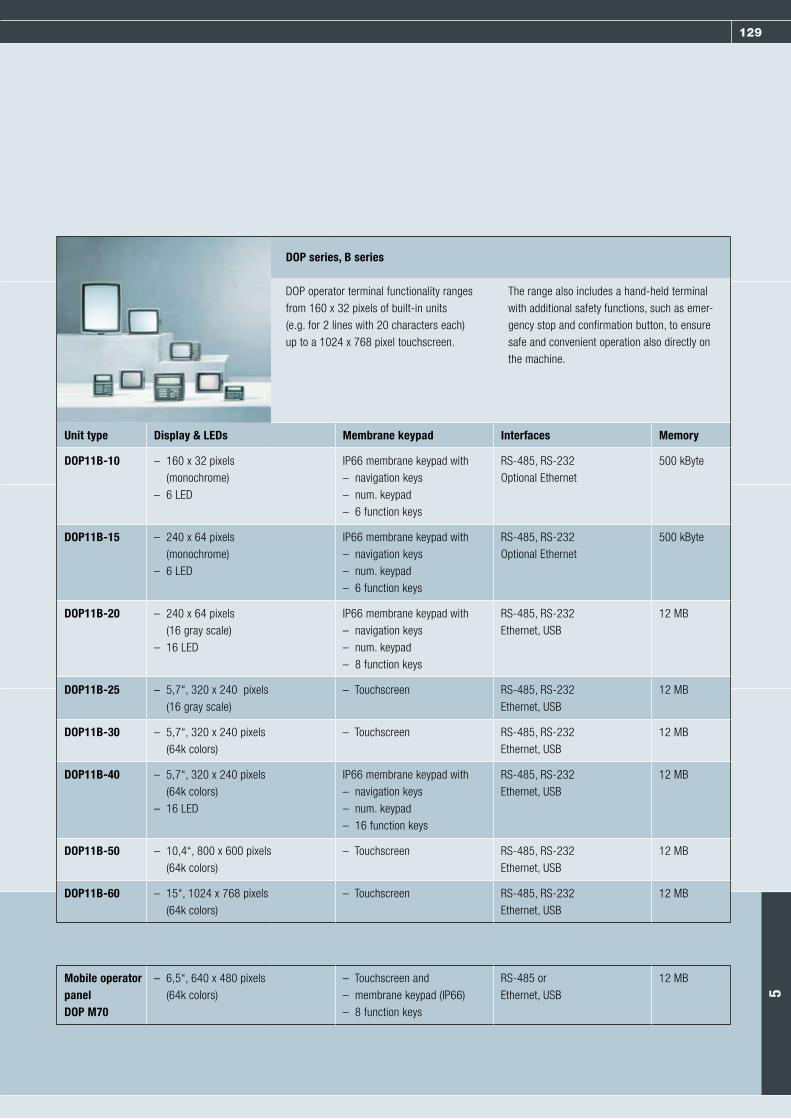
129
DOP series, B series
DOP operator terminal functionality ranges from 160 x 32 pixels of built-in units (e.g. for 2 lines with 20 characters each) up to a 1024 x 768 pixel touchscreen.
The range also includes a hand-held terminal with additional safety functions, such as emer-gency stop and confirmation button, to ensure safe and convenient operation also directly on the machine.
Unit type Display & LEDs Membrane keypad Interfaces Memory
DOP11B-10 – 160 x 32 pixels (monochrome)
– 6 LED
IP66 membrane keypad with– navigation keys– num. keypad– 6 function keys
RS-485, RS-232Optional Ethernet
500 kByte
DOP11B-15 – 240 x 64 pixels (monochrome)
– 6 LED
IP66 membrane keypad with– navigation keys– num. keypad– 6 function keys
RS-485, RS-232Optional Ethernet
500 kByte
DOP11B-20 – 240 x 64 pixels (16 gray scale)
– 16 LED
IP66 membrane keypad with– navigation keys– num. keypad– 8 function keys
RS-485, RS-232Ethernet, USB
12 MB
DOP11B-25 – 5,7“, 320 x 240 pixels (16 gray scale)
– Touchscreen RS-485, RS-232Ethernet, USB
12 MB
DOP11B-30 – 5,7“, 320 x 240 pixels (64k colors)
– Touchscreen RS-485, RS-232Ethernet, USB
12 MB
DOP11B-40 – 5,7“, 320 x 240 pixels (64k colors)
– 16 LED
IP66 membrane keypad with– navigation keys– num. keypad– 16 function keys
RS-485, RS-232Ethernet, USB
12 MB
DOP11B-50 – 10,4“, 800 x 600 pixels (64k colors)
– Touchscreen RS-485, RS-232Ethernet, USB
12 MB
DOP11B-60 – 15“, 1024 x 768 pixels (64k colors)
– Touchscreen RS-485, RS-232Ethernet, USB
12 MB
Mobile operator panelDOP M70
– 6,5“, 640 x 480 pixels (64k colors)
– Touchscreen and– membrane keypad (IP66) – 8 function keys
RS-485 orEthernet, USB
12 MB
5

130 Other system components and services
MOVITOOLS® MotionStudio: Perfect automation –All tools in one modular software system
The more functions drive technology offers, the more important it is to have an effective
tool for operating drives and visualizing processes. MOVITOOLS® MotionStudio operating
software from SEW-EURODRIVE is such a tool. You can use MOVITOOLS® MotionStudio to
communicate with MOVIDRIVE®, MOVITRAC®, MOVIAXIS® and MOVIMOT® inverters and
MQ fieldbus interfaces.
MOVITOOLS® MotionStudio
A software package for consistent engineering: Startup, control, diagnostics, communication and visualization
Characteristics
– Convenient drive startup and parameter setting– Drive diagnostics using the built-in oscilloscope function– Create application and user programs, in high-level languages if required, right on the plant floor using the Assembler or using the graphic
programming interface– View status of connected units– Bus monitor– Control technology functions– Completed application modules for various applications– Read out electronic nameplates
Centralizedsystem concept
– MOVIDRIVE® drive inverter– MOVITRAC® frequency inverters– Fieldbus gateways
Decentralized system concept – Decentralized MOVIFIT® drive controller– MOVIMOT®, gearmotor with integrated frequency inverter– Field distributor
Servo MOVIAXIS® multi-axis servo inverter

131
Tool Functionality
Startup – Configuration and startup: For adapting the inverter to the connected motor and optimizing
current, speed and position controllers.– Manual operation: The tool allows for manually controlling the units directly from the PC.
Parameterization – Parameter tree: Uniform editor for parameter setting of different unit types– PDO Editor: A process data object editor for graphic configuration of process data for the
MOVIAXIS® multi-axis servo inverter.– Gateway configurator: Uniform tool for diagnostics and configuration of the fieldbus gateways
UFx41B, DFx and MOVIFIT® with Classic and Technology function levels
Diagnostics and visualization– Status: Support for unit diagnostics, provides general unit status information, manual unit reset
possible– Application Builder: Editor for creating application-specific visualizations and application-specific
diagnostics. Visualization is connected via data download with the inverter program IPOS and the parameter settings.
– Fieldbus monitor: Diagnostics for communication between fieldbus and unit (monitor modes) and setpoint specification on the unit, controller-independent (control mode)
– Scope: Diagnostics by using an oscilloscope program for all SEW-EURODRIVE inverters
Programming– PLC Editor: Programming the MOVI-PLC® controller series using application programs written
once; can be applied independent of the unit– IPOS® Assembler and Compiler
Technology editors – function-independent:– Motion technology editor for MOVIAXIS® or MOVIDRIVE® technology functions– Single-axis positioning for MOVIAXIS®
5

132 Other system components and services
Parameterizable MOVIVISION® system software
– Designing and dimensioning the system
– Plant data management and administration
– Plant parameterization– Plant startup– Simplification of plant maintenance
– Plant diagnostics– Plant operation and monitoring
MOVIVISION® performs the following tasks:
The new, intuitive MOVIVISION® software solution allows system manufacturers and
operators to startup the materials handling system of their plant, a drive system or an
individual drive quickly and easily without special programming skills and with a minimum
expenditure of time. Even during the production process, the operator can always respond
to manufacturing modifications without tying up human resources to a disproportionately
high extent.

133
Plant overview and operating principle
The combination of central data storage and de-centralized intelligence makes MOVIVISION® the comfortable software solution in materials han-dling technology. The decentralized intelligence simplifies and shortens the complex communi-cation paths between all hardware and software components of the plant. Fastest possible bus cycle and response times on every level ensure a permanent flow of information and commands. This also allows for an object-oriented display.
Each individual user can display the entire pro-duction plant, the drive systems or individual drives.User-friendliness is ensured by the easy-to-use MOVIVISION® interface. The user can perform tasks, e.g. startup or production changes dur-ing operation, quickly and easily, at any time and from any location: simply by setting parameters. Special programming skills are not necessary.
MOVIVISION® configuration and diagnostics tool:The user can access the central database of the MOVIVISION® server via the Windows-based configuration and diagnostics tool PLC/PPS.
MOVIVISION® server
– All data is stored in one central database– A link to the connected, decentralized control components is
established– Data exchange between the server and decentralized control
components is realized via fieldbus and/or networks– Only here, parameters are set or changed– Management and supervision of access authorizations– High degree of data security and user-friendliness
MOVIVISION® client
The interface displays the data of the decentralized control components visually. Parameter and diagnostic data of each unit is displayed separately. Both nodes are divided into the– Drive level– Positioning level– Technological level
It is possible to grant different access rights to the users, e.g. for monitor-ing, for parameter setting, for initial startup, for replacing units, etc.
5
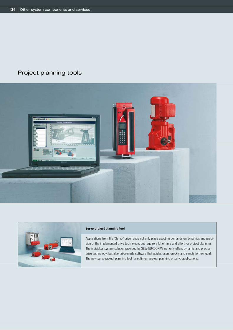
134 Other system components and services
Project planning tools
Servo project planning tool
Applications from the “Servo” drive range not only place exacting demands on dynamics and preci-sion of the implemented drive technology, but require a lot of time and effort for project planning. The individual system solution provided by SEW-EURODRIVE not only offers dynamic and precise drive technology, but also tailor-made software that guides users quickly and simply to their goal: The new servo project planning tool for optimum project planning of servo applications.

135
EPLAN® makros
SEW-EURODRIVE offers ready-made EPLAN® 5.50 macros for faster generation of wiring diagrams using CAE/CAD programs. The macros enable the user to create a standard layout, adapted to the typical EPLAN® functions. The SEW-EURODRIVE product range is displayed in an easy-to-use tree structure. Simply select the product required and the data is displayed automatically in EPLAN® format. A tremendous amount of time is saved whenever you generate a wiring diagram because you no longer have to create your own illustrations or format the data. Macros are available for the decentralized technology, MOVIDRIVE® and MOVITRAC® B product groups.
Sample programs for SIMATIC STEP7
Time-consuming and expensive startup procedures are a thing of the past: SEW-EURODRIVE provides sample programs on the Internet at no cost. These programs make project planning, programming, diagnostics and communication with the SIMATIC STEP7 programmable logic controller user-friendly and reliable. The sample programs contain S7 sample control programs for MOVIMOT® gearmotors, MOVITRAC® B frequency inverters, MOVIDRIVE® drive inverters and MOVIAXIS® multi-axis servo inverters. S7 sample modules are also available for operating the DP-V1 parameter channels.
5

136 Other system components and services
Fieldbus concepts
Ethernet – A bus system offering numerous advantages
Vertical and horizontal integration with Industrial Ethernet
Realtime capable process data communication between the controller and the drive technology (soft realtime with 10 process data words per slave)
Fast data transfer at 100 Mbit/s
Diagnostics for drive technology via Internet Explorer
Programming and diagnostics for the drive technology can be carried out via Ethernet, which makes remote maintenance easy to handle
Broadband data communication between the master level and field level
Control and engineering combined in one bus system
Fast, integrated info system configuration
Functions
Process data communication by means of protocol, either PROFINET IO/RT, EtherNet/IP or Modbus TCP, for simple and fast access to data at the master and field levels
Control and diagnostics via Ethernet – Local operation, diagnostics and maintenance at the field level
Integrated web server to diagnose drive technology using the Internet Explorer
Central data backup at master level
Parameter setting and programming using MOVITOOLS® MotionStudio via Ethernet
Reduction of installation costs and maintenance due to installation of only one diagnostic bus
Industrial Ethernet
Information technology is becoming increas-ingly important in industrial systems. Techni-cal product data should be able to be called up at every PC in the company at the touch of a button, without additional manufacturer-specific software. At the same time, vertical
data communication at the control level is to be available over a broad bandwidth as is hor-izontal process data communication between the controller and the application (e.g. drive inverters).

137
MOVITRAC® frequency inverters with DFE24A
MOVIDRIVE® inverters with DFE24A
EtherCAT and Motion Control – High-speed Industrial Ethernet
Servo drive systems:MOVIAXIS® multi-axis servo drive with XFE24A
Applications with SEW drives, connected via DFE24B gateway
Motion control:With synchronization via distributed clock and a synchronization cycle of 0.5 ... 10 ms, the hard realtime communication for MOVIDRIVE® invert-ers and MOVIAXIS® multi-axis servo inverters allows for the following operating modes:– High-performance Motion Control operation
with centrally calculated motion functions and clock-synchronous speed, position or torque settings
– Use of integrated Motion Control functions such as electronic cam, electronic gear unit, touch probe, positioning, etc. through clocksynchronous control
– Conventional PLC operation
PLC operation:In conventional PLC operation, non-synchronized process data (such as control and status values, speed or position setpoint or actual values) are transfered. This allows for control of application modules (positioning, modulo, winder, etc.) in the MOVIDRIVE® inverter, but also enables MOVITRAC® frequency inverters and other SEW drives with SBus interface to be used for simple drive tasks.
The mailbox gateway in the EtherCAT master ensures unlimited engineering access, for example, for MOVITOOLS® MotionStudio down to the drive level.
5

138
Other system components and services
The Drive Benefits from SEW-EURODRIVE offer a variety of practice-oriented possibilities to
accelerate processes in every value creation phase, to make these processes easier and
handle them in a cost-optimized manner. Selecting the suitable components and combining
them to form an overall concept will give you sustainable benefits.
Drive Benefits – Customized process solutions for your entire value creation chain
– Measurable cost savings– Less expenditure of time– Increased process safety– Increased efficiency– Enhanced process automation
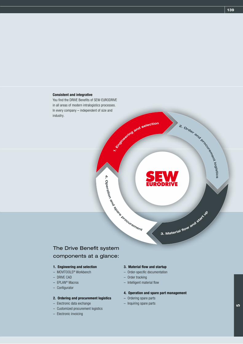
139
Consistent and integrativeYou find the DRIVE Benefits of SEW-EURODRIVE in all areas of modern intralogistics processes. In every company – independent of size and industry.
1. Engineering and selection– MOVITOOLS® Workbench– DRIVE CAD– EPLAN® Macros– Configurator
2. Ordering and procurement logistics– Electronic data exchange– Customized procurement logistics– Electronic invoicing
3. Material flow and startup– Order-specific documentation– Order tracking– Intelligent material flow
4. Operation and spare part management– Ordering spare parts– Inquiring spare parts
The Drive Benefit system
components at a glance:
4. O
pe
ratio
n a
nd sp
are procurement3. Material f o
w and sta
rt u
p
1. E
ngin
eering and selection
2. Order and procure
ment lo
gis
tics
5

140 Services
CDS® – Complete Drive Service Green light for your production
CDS® – Complete Drive Service from SEW-EURODRIVE offers system operators a complete
range of services for all aspects of drive technology. CDS® covers any service requirement
from machines and systems across the entire product life cycle of the drive components
and lets operators optimally plan and calculate these requirements in the long term

141
You can combine the individual CDS® system modules to form your individual service package. In this way, we provide exactly the system mod-ules you need to meet your specific requirement
profiles. The result will be higher availability for your system with downtimes reduced to a minimum.
Integrative services that can be tailored to the specific needs of every phase of the product life cycle make the Complete Drive Service from SEW-EURODRIVE the perfect solution. From
project planning to retrofit and modernization measures – CDS® covers the entire life cycle of a system.
CDS® in the product life cycle
The CDS® system modules – Our services at a glance
A complete service concept – module for module
24-hour service hotline01805 7394357 01805 SEWHELP
Repair service
Retrofit service
Installation consulting service
Spare parts service
Condition monitoring service
Startup service
Express assembly service
CDM® maintenance management
Applikations Application programming service
Industrial gear unit service
Training service
Inspection and maintenance service
Collection and delivery service
5
142 Other system components and services
DriveAcademy® – Training made by SEW-EURODRIVE
The DriveAcademy® in Bruchsal is designed in such a way that it offers employees and
customers of SEW-EURODRIVE the ideal learning environment. Seminars, teachware and
models show state-of-the-art technology and provide ample of room for individual learn-
ing objectives. The training courses and seminars are held in Bruchsal and at six Service
Competence Centers all over Germany.
With target-group-specific product trainings for planners, project planners, design engi-neers, service engineers, repair staff, startup engineers, as well as trainers and teachers, the
DriveAcademy® provides ideal conditions for hands-on experience with modern drive technology.
The consulting experts of WIEPROconsulting implement individual know-how into integrative competence. Their focus is on practical
improvements of business processes as well as internal processes.
The wide range of seminars covers manage-ment training, communication and personnel
related topics through to specific working methods and individual coaching.
Training for Drive
WIEPROconsulting – Always well advised
Modern personnel development
DriveAcademy®-Onlinewww.driveacademy.sew-eurodrive.com

143
DriveGate – The customer service portal
DriveGate offers customers of SEW-EURODRIVE a wide range of services. It is the central
online platform of SEW-EURODRIVE that provides numerous options for improving and
optimizing internal processes, including expert consultation, in a convenient and clearly
structured manner.
The SEW Workbench is a planning and configu-ration tool to specify SEW-EURODRIVE products. Simple and clearly arranged graphical elements let you create complex configurations and verify their proper functioning. A great number of new functions offer additional options for creating exactly the drive solution required for the spe-
cific application. The SEW Workbench includes a complete electronic product catalog, all required documentation, and an option for creating indi-vidual CAD files. The SEW Workbench DVD pro-vides customers of SEW-EURODRIVE with a per-sonal code for easy registration to the DriveGate customer portal.
The “Drive Engineering - Practical Implementa-tion” series of publications as well as various documentations (docu ROMs) and presentations (CBI-ROM) on CD-ROM are the ideal tools of reference for any question on drive technology.
They also include detailed basic information, ex-planations, and useful tips. All this is arranged in a clear structure and with the focus on practical applications.
The advantages at a glance
– Registration and login free of charge– User-friendly user interface– Clear design
– Fast and direct access– Many convenient download functions– Available 24 hours a day, worldwide
SEW Workbench
Useful reference tools
[email protected] SEW-EURODRIVE’s DriveGate offers uncomplicated access, for example, to
5

Products and Innovations
Spring 2009
Drive Technology \ Drive Automation \ System Integration \ ServicesSEW-EURODRIVE—Driving the world
For every motion in your machines and systems and for every industry: As a leading drive technology specialist, we always supply the right drive. This includes not only gear units, motors or drive electronics, but also the matching controller and a comprehensive service portfolio. This is what we call Drive 360° – Seeing the big picture: From system availability to problem-solving competence, from low operating costs over energy efficiency to the complete system that handles all your tasks.
www.sew-eurodrive.com
Seeing the big picture.
Seeing the big picture.
Seeing the big picture.
Seeing the big picture.
Seeing the big picture.
Seeing the big picture.
Seeing the big picture.
Seeing the big picture.
From the first idea to the running system, and beyond.
1677
001
3 /
0409