production and 3d printing processing of bio-based
TRANSCRIPT

Production and 3D printing processing of bio-basedthermoplastic filament
Eleni Gkartzou, Elias P. Koumoulos, and Costas A. Charitidis*
Research Unit of Advanced, Composite, Nano Materials & Nanotechnology, National Technical University of Athens,School of Chemical Engineering, 9 Heroon Polytechniou St., Zographos, Athens 15780, Greece
Received 22 July 2016 / Accepted 22 October 2016
Abstract – In this work, an extrusion-based 3D printing technique was employed for processing of biobased blendsof Poly(Lactic Acid) (PLA) with low-cost kraft lignin. In Fused Filament Fabrication (FFF) 3D printing process, ob-jects are built in a layer-by-layer fashion by melting, extruding and selectively depositing thermoplastic fibers on aplatform. These fibers are used as building blocks for more complex structures with defined microarchitecture, inan automated, cost-effective process, with minimum material waste. A sustainable material consisting of ligninbiopolymer blended with poly(lactic acid) was examined for its physical properties and for its melt processability dur-ing the FFF process. Samples with different PLA/lignin weight ratios were prepared and their mechanical (tensiletesting), thermal (Differential Scanning Calorimetry analysis) and morphological (optical and scanning electron mi-croscopy, SEM) properties were studied. The composition with optimum properties was selected for the production of3D-printing filament. Three process parameters, which contribute to shear rate and stress imposed on the melt, wereexamined: extrusion temperature, printing speed and fiber’s width varied and their effect on extrudates’ morphologywas evaluated. The mechanical properties of 3D printed specimens were assessed with tensile testing and SEMfractography.
Key words: 3D Printing processability assessment, Fused filament fabrication, Additive manufacturing, Biobased3D printing filament
1. Introduction
In the last decade, issues concerning environmental pollu-tion and the increasing awareness of limited resources, havemotivated the scientific community to study and optimizerenewable alternatives to traditional petroleum-derived plastics,like biobased composite materials that are sourced from car-bon-neutral feedstocks [1]. Lignin is a highly aromaticbiopolymer, abundantly found in the fibrous part of variousplants and extracted as a byproduct of wood pulping industries.Kraft lignin (sulfate lignin) is isolated in the so-called deligni-fication process, from black liquor by precipitation and neutral-ization with an acid solution (pH = 1–2), and subsequentlydried to a solid form [2]. It is estimated that only 2% of theindustrially extracted lignin is exploited for low-volume, nicheapplications, while the rest is often relegated to a low efficiencyenergy recovery via combustion or as a natural component ofanimal feeds [3]. Thus, the development of ways to convert lig-nin to new high-value products is an active area of research,
dealing with the main drawbacks of lignin usage regardingthe low-purity standards, heterogeneity, smell and color prob-lems of the existing commercial lignins. It is recognized thatblending lignin with polymers is a convenient and inexpensivemethod to create new materials with tailored properties, suchas hydrophobicity, stiffness, crystallinity, thermal stability,Ultraviolet (UV) blocking ability and to reduce the overall costof the material [4, 5].
The ecosystem of 3D printing plastic market consists ofnumerous research and development activities and is projectedto reach USD 692.2 Million by 2020, at a Compound AnnualGrowth Rate (CAGR) of 25.7% from 2015 to 2020 [6]. Amongthe various commercially available specialty filaments forFused Filament Fabrication (FFF) processing, materials mim-icking wood texture and properties are a separate category,because of their ability to create objects with the tactile feelof wood without any need for specialized woodworking tools.Furthermore, they require less maintenance and preservatives,since they are more resistant to organic decomposition, whilemaintaining their biodegradability. PLA/Lignin (poly(lacticacid)/Lignin) 3D printing filaments are an alternative option*e-mail: [email protected]
Manufacturing Rev. 2017, 4, 1� E. Gkartzou et al., Published by EDP Sciences, 2017DOI: 10.1051/mfreview/2016020
Available online at:http://mfr.edp-open.org
This is an Open Access article distributed under the terms of the Creative Commons Attribution License (http://creativecommons.org/licenses/by/4.0),which permits unrestricted use, distribution, and reproduction in any medium, provided the original work is properly cited.
OPEN ACCESSRESEARCH ARTICLE

for lignin exploitation and filament cost reduction and can beused in rapid prototyping, presentation models and consumerproducts, among others. Poly(lactic acid) is a biodegradablethermoplastic, which is produced via fermentation or chemicalsynthesis from a bio-derived monomer, lactic acid (2-hydroxypropionic acid) [7]. The carbon in PLA originates from atmo-spheric carbon dioxide, which is immobilized in glucose byphotosynthesis; therefore, its impact on the environment duringproduction and disposal (carbon footprint) is low compared toother petro-based polymers. PLA is widely used in 3D printingapplications, since it is one of the most user-friendly materialsthat can be easily processed with FFF, without emitting toxicfumes. However, its low thermal stability, high degradation rateduring processing and brittle behavior have to be addressed. Ithas been suggested that the presence of lignin increases ther-mal stability and flammability under oxidative and nonoxida-tive conditions, due to the formation of char, which acts as aprotective layer preventing oxygen diffusion [8].
Extrusion-based 3D printing techniques use temperature asa way of controlling the material state, for the successful extru-sion and deposition of semi-molten thermoplastic fibers, on aflat surface. In a typical FFF process, a filament feedstock issupplied to the system by an electric motor-controlled pinchroller mechanism [9, 10]. Material is liquefied inside a reser-voir, contained in a heated metal block with a machined chan-nel, so that it can flow through the print head’s nozzle and fusewith adjacent material before solidifying. This approach issimilar to conventional polymer extrusion processes, exceptthe extruder is vertically mounted on a plotting system (printhead) rather than remaining in a fixed horizontal position[10]. After its deposition, the solidifying material is referredto as a fiber or road. The part is produced by superimposinga specified number of layers, where each of them is generatedby a specific pattern of fibers. The formation of bonds amongindividual fibers in the FFF process consists of complicatedheat and mass transfer phenomena coupled with thermal andmechanical stress accumulation and phase changes. Thestrength of these bonds depends on the growth of the neckformed between adjacent fibers and on the molecular diffusionand randomization at the interface [11]. As a natural conse-quence of this manufacturing approach, the part’s internalmicrostructure consists of fibers with partial bonding amongthem and voids [12] and can be assimilated to a compositetwo-phase material with inherently orthotropic properties[13]. Individual fibers are significantly stronger in the axialdirection and resemble the fibers in a composite; however,the structure shows weaker behavior in the direction wherestresses need to be carried through fiber-to-fiber or layer-to-layer adhesion [12].
Three dimensional printers employing the FFF technologyare Computer Numerical Control (CNC) machines, whosefunction is defined by a program containing coded alphanu-meric data (G-code). G-code sets of commands are typicallygenerated by Computer-Aided Manufacturing (CAM) soft-ware, which uses topological information from 3D Com-puter-Aided Design (CAD) data along with user-definedprocessing and toolpath parameters, to create virtual slices ofthe object to be manufactured and to calculate the toolpathand the material’s Volumetric Flow Rate (VFR), in order to
form the successive cross sections of the physical part. In mostCAM programs for lower end FFF 3D printers, VFR is a func-tion of the linear feed velocity of the filament and of severaldesign parameters related to the toolpath (e.g. the width andheight of individual fibers, defined by extrusion width andlayer height parameters) [14]. The pressure-driven mass flowof the non-Newtonian polymeric melt through the nozzle ismainly related to nozzle geometry, pressure drop and melt’sapparent viscosity. This flow can be described as a fully devel-oped, laminar flow through a capillary die with a circular crosssection [14, 15]. The necessary pressure for fiber extrusion isapplied by the solid portion of the 3D printing filament whichacts as a piston, as it is pushed by a pinch-roller feed mecha-nism into a melting reservoir, placed on the upper part of thenozzle. Volumetric flow rate along with extrusion temperatureare two material-dependent factors which contribute on theshear rate and stresses imposed on the melt during extrusion.In the case of composite 3D printing materials, these factorsare significantly influenced and limited by the filler’s dispersionand agglomeration [16].
This study is divided in two main sections; the first sectioninvolves the preparation and characterization of bulk samplesof the composite material with increasing lignin content and3D printing filament production. The second section concernsthe selection of suitable toolpath and process parameters basedon the produced filament’s response during FFF processing,focusing on extrusion temperature, print head’s velocity andextrusion width. By understanding the relationship betweenprocessing conditions and physical phenomena involved inthe material’s extrusion and deposition, suitable bounds forthese parameters were derived. The optimum velocity and tem-perature values were used for the fabrication of tensile speci-mens with 100% nominal density and three differentextrusion widths, produced by three brass nozzles with differ-ent diameter (0.2, 0.3 and 0.4 mm), in order to measure thetensile properties of the finished parts and to compare themwith the properties of the bulk material. Pure PLA filamentwas produced and processed under the same conditions, tobe used for comparison. Fractographic analysis of tensile fail-ure was carried out with Scanning Electron Microscopy(SEM). Also, a qualitative assessment of the filler’s dispersionand agglomeration into the polymeric matrix, as well as itseffect on surface morphology and diameter of individual fiberswas made with optical microscopy.
2. Experimental details
2.1. Materials
Commercial PLA pellets under the grade name ‘‘INGEO2003D’’ were supplied by Natureworks LLC, with numberaverage molecular weight Mn (g/mol) = 114.317, weight aver-age molecular weight Mw (g/mol) = 181.744 and 4.3 wt.%D-isomer content [17]. A purified form of kraft pine lignin(Indulin AT) was supplied by MWV Specialty Chemicals, inthe form of free-flowing powder with a wide distribution ofparticle diameter, as depicted in the SEM micrographs ofFigure 1. Both materials were used without chemical treatment
2 E. Gkartzou et al.: Manufacturing Rev. 2017, 4, 1

for the preparation of the blends. Prior to processing, the com-ponents were vacuum-dried at 50 �C for 24 h and weighted ina high precision scale.
2.2. Blending
Firstly, 40 g samples of PLA/Lignin blends with differentlignin concentrations (5, 10, 15, 20% percentage by weighton the dry polymer – Table 1) were prepared by melt mixingin a twin-screw Brabender internal mixer. Mixing time for eachsample varied from 10 to 13 min, at 35 rpm rotating speed ofthe screws and mixing temperature between 180–190 �C (de-pending on lignin content). To remove residual stresses andair bubbles caused by the blending process, the semi-moltenmaterial was collected from the mixing chamber and placedin an aluminum mold, which was inserted in a Dake thermo-press to form a 15 · 60 · 1 mm plate. The plates of the ther-mopress were heated at 120 �C and heating was switched offwhen maximum load was applied on the mold. All samplesused for the bulk material’s characterization were cut fromthe aforementioned plates and kept under room temperaturein a glass desiccator, to prevent moisture absorption.
2.3. Characterization
The effect of increasing lignin content on the bulk mate-rial’s thermal and mechanical properties was evaluated withDifferential Scanning Calorimetry (DSC) and tensile testing.The phase morphology of the samples was examined with anAxio Imager A2m optical microscope and AxioCam ICc5CCD camera (Carl Zeiss, Oberkochen, Germany) and SEMmicrographs were taken with Nova NanoSEM 230 scanningelectron microscope (FEI Company) with an acceleration volt-age of 5 kV. Samples for optical inspection were cut with arotating saw and embedded in cold mounting epoxy resin.The embedded samples’ surface was grinded with fine siliconcarbide abrasives to remove defects introduced by sectioning.Tensile specimens were directly cut from the thermopressedplates of the compounded material with a dumbbell-shapedspecimen cutting die, with a 18 · 3 · 1 mm reduced gage sec-tion. Measurements of mechanical properties of specimens
were performed at room temperature with a Zwick tensile tes-ter, model 1120 equipped with a 2000 N load cell. BothYoung’s modulus and elongation measurements were made ata constant crosshead speed of 2 mm/min. Each value ofmechanical properties reported is an average of five specimens.DSC analyses were performed with DSC Q200 TA Instruments(New Castle, DE, USA). The thermal history of samples waserased by a preliminary heating cycle, followed by a coolingcycle from 200 to 0 �C and a second heating cycle from 0to 200 �C. Both cooling and heating rates were set at 10 �C/min. The samples’ mass ranged from 6.90 to 8.36 mg and theywere encapsulated in aluminum pans. An empty pan wasused as reference. The glass transition temperature (Tg) coldcrystallization temperature (Tcc), double melting peak temper-atures (Tm1,2), cold crystallization enthalpy (DHcc) and meltingenthalpy (DHm) were determined from heating scans. Thermo-gravimetric Analysis (TGA) of softwood kraft lignin was car-ried out based on global mass loss with a Netzsch 409 EPanalyzer, from which lignin’s decomposition pattern can bederived. The analysis was conducted under nitrogen atmo-sphere with a heating rate of 10 �C/min. The characterizationof 3D printed fibers and tensile specimens involved opticalmicroscopy and tensile testing. Brightfield illumination wasused to observe the surface roughness of PLA/Lignin fibers.Also, by exploiting PLA’s transparency and alterations in theincident light’s state of polarization during its interaction withlignin, a qualitative evaluation of the dispersion of lignin’sagglomerates in the fibers’ bulk volume was conducted. Axio-Visio digital image processing software was used to measurethe diameter of the fibers from the micrographs captured bythe CCD camera. Since no special standard exists for the char-acterization of FFF parts, tensile specimens based on a scaled
Table 1. Sample composition.
Sample PLA wt.% Lignin wt.%
LPLA00 100 0LPLA05 95 5LPLA10 90 10LPLA15 85 15LPLA20 80 20
(a) (b)
Figure 1. SEM micrographs of kraft lignin (Indulin AT) particles (a) ·800 and (b) ·1.600 magnification.
E. Gkartzou et al.: Manufacturing Rev. 2017, 4, 1 3

down version of ASTM D638 Type I with a 36 · 8 · 2 mmgauge section, were 3D printed using Zmorph 2.0 S, a com-mercial FFF Cartesian XZ system (Zmorph LLC, Wroclaw,Poland). Tensile testing was carried out under the same condi-tions as the bulk material specimens, with the same crossheadspeed of 2 mm/min. Both pure PLA and composite PLA/Lignin filaments were used as raw materials. The 3D printedspecimens had 100% infill density in order to make a compar-ison with the tensile properties of the bulk material and toeliminate errors from G-code generation. Divergence fromthe nominal dimensions of the tensile specimens introducedby the fabrication process, was measured for each specimenwith a high precision digital caliper and the average of 10 mea-sured values for each dimension was used for stress calcula-tions. Fractographic analysis of tensile failure was carried outwith scanning electron microscopy. The fractured sampleswere sputter-coated with a thin layer of gold beforeobservation.
2.4. Production of 3D printing filament
The 3D printing filament needs to be able to provide andsustain the pressure needed to drive the extrusion process.Failure to do this results in filament buckling, which occurswhen the extrusion pressure is higher than the critical bucklingload that the filament can support [10, 14, 18]. The filament’selastic modulus determines its load carrying ability and meltviscosity determines the resistance to extrusion (or extrusionpressure). As a result, the composition with 5 wt.% lignincontent was selected for the production of 3D printing filamentwith 1.75 mm nominal diameter, which is compatible with the3D printer’s feeding system. Subsequently, a Boston-Mathewssingle-screw extruder with an L:D ratio of 25:1 with a 1.8 mmdiameter extrusion die was used to obtain PLA/Lignin filamentand several combinations of process parameters were tested inorder to achieve enhanced filler dispersion and constantfilament diameter. A processing temperature profile of185–195–205–205–195 �C from feed section to die wasselected along with a fixed screw speed at 16 rpm. The extru-date was collected by a conveyor belt equipped with coolingfans, whose speed was matched to the extrusion speed inorder to control the diameter of the filament. The compositefilament and pure PLA filament (processed under a180–190–200–200–190 �C temperature profile) were used toobtain 3D printed specimens and individual fibers. The pro-duced filament was conditioned in room temperature insidesealed plastic bags, in the presence of silica gel, to avoid mois-ture absorption. Filament sections with tight tolerances wereselected for specimen fabrication. Each section’s diameterwas measured every 1 cm with a high precision digital caliperand average diameter and standard deviation were calculated.From Figure 2 it can be seen that the measured filamentdiameters are normally distributed around the mean value,with 0.02 mm standard deviation, meaning that 95% of thefilament used has a ±0.04 tolerance. A tight diametertolerance is important during the material melting anddeposition process. The heating of the filament inside the print
head’s liquefier can be considered as a two-dimensional,axisymmetric, steady-state, advection-conduction heat transferprocess [19]. Gaps between the filament and the wall of theliquefier, caused by the filament’s diameter inconsistency canbe expected to hinder heat transfer and result in irregularviscous behavior of the melt on the upper part of the liquefier.Diameter inconsistencies have adverse effects on the material
Figure 2. Diameter distribution of filament sections used forspecimen fabrication.
Figure 3. Illustrations of toolpath for rectilinear infill pattern with90� raster angle generation and cross sections of the producedpattern and individual roads, where Wr is the extrusion width, Hr islayer height and dr is raster-to-raster distance.
4 E. Gkartzou et al.: Manufacturing Rev. 2017, 4, 1

feeding mechanism as well, since mismatches between theroller and filament surfaces may lead to filament slipping.Furthermore, the filament’s mean diameter is used by the Com-puter Aided Manufacturing (CAM) program, which automati-cally calculates the material’s feed velocity in the 3D printer’sextruder. As a result, the diameter’s standard deviation isrelated to volumetric flow rate fluctuations during the 3D print-ing process, which can alter the distance between adjacentfibers, causing insufficient bonding or fiber overlapping andthus reducing the physical object’s dimensional accuracy andstructural integrity.
2.5. Computer aided manufacturing – toolpathand process parameters
Computer aided manufacturing software typically enablescontrol of several design and process parameters related tofused filament fabrication. Design parameters define the tool-path followed by the nozzle’s tip and include individual fibers’width and height (commonly referred to as ‘‘road/extrusionwidth’’ and ‘‘layer’s height/thickness’’, respectively), as wellas various deposition strategies to form and fill the successivecross sections of the part. A common deposition strategy is toseparately deposit one or more continuous contours of allboundary 2D surfaces included in a given cross section andto fill the space between them, (corresponding to the part’sinterior), with specific infill patterns. Part orientation in relationto infill orientation and to the system’s main axes of movement(XYZ for cartesian 3D printers) plays an important role in sur-face finish, dimensional accuracy, cost and mechanical behav-ior [20, 21]. In the simple case of rectilinear infill pattern(Figure 3), each layer is filled with a raster of parallel roadsand adjacent layers have a fixed 90� raster angle between them.By adjusting infill density, which is expressed as a percentageof occupied space, more sparse or dense parts can be producedwith bigger or smaller distances among contiguous fibers ofthe same layer (raster to raster distance, dr). A slightly negativedr, corresponding to fiber overlapping, has been reported toreduce void density and increase contact area among fibersand thus resulting in stronger fiber-to-fiber bonds [22, 23].However, the excessive material buildup at the layer’s perime-ter significantly affects dimensional accuracy on the XY plane.As individual fibers are deposited on the previously solidifiedlayer of the material, heat exchanges by conduction developon contact surfaces between adjacent fibers and by convectionand radiation with the surroundings. Upon the deposition of
new layers, new physical contacts are generated; hence, severalheat transfer modes change and heat transfer with air entrappedbetween contiguous filaments may also develop. Toolpath andG-code generation have a significant effect on thermal stressaccumulation in fibers and layers and thus different CAM pro-grams with the same input values, produce parts with differentresponses to external stresses. In this study, an open-sourceG-code generating program (Slic3r 1.2) was used for specimenfabrication. A second G-code generating program (Voxelizer1.4), with a different generating algorithm, was used with thesame input values of toolpath and process parameters, in orderto estimate the effect of different CAM programs on themechanical properties of the final part.
As far as process parameters are concerned, theyinclude extrusion temperature, chamber temperature, coolingrate, filament feed velocity and volumetric flow rate, amongothers. The extrusion process does not have a considerableinfluence on the strength and modulus of the material, butnotably affects the maximum strain, since during extrusionthrough the nozzle, polymer chains are submitted to stress-induced orientation, which reduces the elongation characteris-tics of the material [12]. The rate at which the filament is fed tothe liquefier (feed velocity) is dynamically controlled and con-nected to velocity changes of the print head, in order to main-tain a constant volumetric flow rate. The amount of melt whichis present in the reservoir, the temperature of the melt, and con-sequently, the viscosity and surface energy of the melt, varywith feed rate [14]. In the case of constant linear movementof the print head, the extruder motor speed is proportionateto printing speed, so an indirect control of feed speed can beachieved varying printing speed for the same toolpath charac-teristics. Extrusion temperature and deposition rate are identi-fied as the major parameters influencing inter- and intra-layerbonding [24].
User-defined processing parameters for G-code generationand specimen fabrication are listed in Table 2, which resultedfrom temperature and printing speed optimization, as well asadjustments on the standard processing profile for PLA recom-mended by the manufacturer. A constant layer thickness of0.1 mm was used for all specimens and extrusion widths weredetermined by nozzle diameter. Three nozzles with the samedesign characteristics and 0.2, 0.3, 0.4 mm openings weretested and extrusion width was set equal to the respective noz-zle diameter. Nozzle diameter, along with the viscosity of themelt, determine the pressure drop during extrusion and thus theforce required from the feed mechanism. Pressure dropincreases as nozzle diameter increases, or as feed velocity
Table 2. Fused filament fabrication toolpath and process parameters.
Toolpath parameters Process parameters
Layer height (mm) 0.1 Speed for non-print moves (mm/s) 100 Filament diameter (mm) 1.78 ± 0.04Vertical shells (#) 3 Speed for print moves (mm/s) 20 Extrusion multiplier 1Horizontal shells (#) 0 Infill/perimeters overlap (mm) 0.15 Extrusion temperature (�C) 205Seam position Aligned First layer speed (mm/s) 10 Building platform heating OffInfill density (%) 100 Extrusion width (mm) Equal to nozzle diameter Fan speed (%) 20Infill pattern Rectilinear Infill/perimeters overlap (mm) 0.1 Disable fan for the first 2 LayersInfill angle (degree) 90 Minimum detail resolution (mm) 0.02
E. Gkartzou et al.: Manufacturing Rev. 2017, 4, 1 5

increases. Furthermore, in the vicinity of the nozzle, the poly-mer melt is under stress and part of the deformation energystored elastically leads to radial expansion of the fiber afterextrusion. Individual fibers were extruded from each nozzleat three print speeds (20, 40 and 60 mm/s). Surface morphol-ogy and diameter were studied at the center of the fibers, inorder to avoid errors related to print head acceleration anddeceleration. Since no standard test specimens exists for char-acterization of parts processed with FFF, tensile specimenswere fabricated based on a 3D model of ASTM D638 StandardTest Method for Tensile Properties of Plastics, Type I speci-men, designed with Autodesk Fusion 360 CAD and extractedin fine quality Stereolithography (STL) format. The originalspecimen was scaled down by ·0.6 to avoid fabrication errorsnear the boarders of the available working volume. To ensurethe repeatability of the fabrication process, all tensile speci-mens were fabricated separately, with their wide surface paral-lel to the XY plane and gauge section parallel to X axis, at the
same position near the center of the build platform. Toolpathsimulation generated by G-code generating software isdepicted in Figure 4. Before the fabrication of each specimen,a touch probe sensor (by Zmorph LLC) was used for preciseleveling of the build platform and the nozzle’s distance fromsurface (0.1 mm) was verified at four points within the surfaceof specimen fabrication.
3. Results
3.1. Bulk material characterization
3.1.1. Reflected light microscopy
The morphological analysis of binary PLA/Lignin blendswas performed with reflected light microscopy and scanningelectron microscopy. In general, the morphology is definedby the complex thermomechanical history experienced by the
Figure 4. Toolpath simulation for tensile specimen fabrication with three contours and rectilinear infill pattern with 100% nominal density.Specimens consist of alternating Type A and Type B layers.
Figure 5. (a–b) Reflected light (brightfield and polarized illumination) micrographs of PLA/Lignin with 5% lignin (magnification ·100 and·500). (c–d) Closer examination (·4000 and ·8000 magnification) of the morphology of lignin aggregation with SEM, from the tensile-fractured surface of sample with 15% lignin.
6 E. Gkartzou et al.: Manufacturing Rev. 2017, 4, 1
different constituents during processing [25]. All samplesformed heterogeneous systems, due to the low compatibilitybetween PLA matrix and the unmodified kraft lignin, whichhas been previously reported [24–28]. At 5 wt.% lignin con-tent, the morphology mainly consists of a uniform dispersionof lignin aggregates of small size (<20 lm) in homoge-neous surrounding matrix of PLA/Lignin, as it can be seenat Figures 5a and 5b. At higher lignin content, there is anincrease in aggregates’ concentration, which remained uni-formly dispersed. At 20% lignin, particle size increasesbecause of coalescence phenomena.
A closer examination of lignin aggregation at smallerscales can be achieved from SEM analysis of the fractured sur-face of the samples (Figures 5c and 5d). Prior to examination,sample surfaces were covered with gold sputter coating. It canbe seen that lignin aggregates consist of smaller lignin domainsof fairly circular shape, closely packed in specific regions ofthe PLA matrix. Interfacial separation and sliding between lig-nin’s aggregates and the surrounding matrix are indicative ofvery weak secondary interactions between the two polymers.
3.1.2. Tensile testing
The type of morphology and the phase dimensions deter-mine the mechanical and physical properties of the blend atlarge, which is influenced by intermolecular lignin-lignin,PLA-PLA and PLA-lignin interactions. Consequently, theobserved immiscibility between the two constituents resultsin minor effective stress transfer between lignin’s aggregatesand PLA matrix and increases PLA’s brittleness, which isshown as a significant reduction in the plastic region ofstress-strain curves and disappearance of yield point. However,
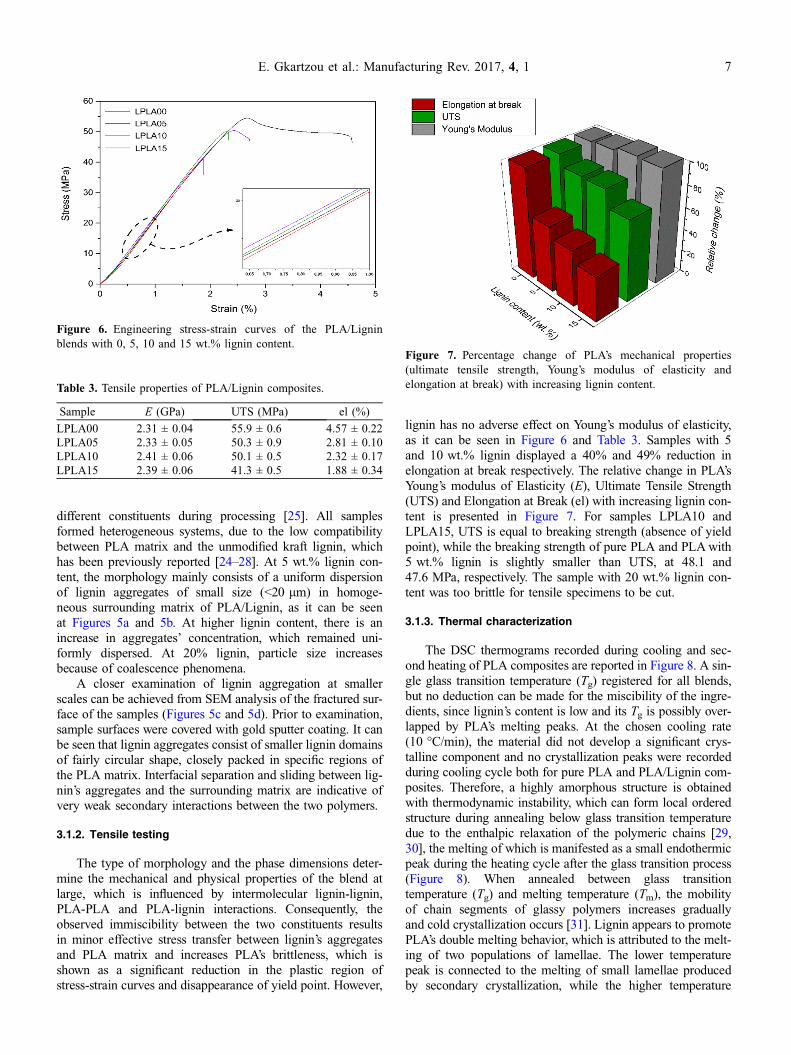
lignin has no adverse effect on Young’s modulus of elasticity,as it can be seen in Figure 6 and Table 3. Samples with 5and 10 wt.% lignin displayed a 40% and 49% reduction inelongation at break respectively. The relative change in PLA’sYoung’s modulus of Elasticity (E), Ultimate Tensile Strength(UTS) and Elongation at Break (el) with increasing lignin con-tent is presented in Figure 7. For samples LPLA10 andLPLA15, UTS is equal to breaking strength (absence of yieldpoint), while the breaking strength of pure PLA and PLA with5 wt.% lignin is slightly smaller than UTS, at 48.1 and47.6 MPa, respectively. The sample with 20 wt.% lignin con-tent was too brittle for tensile specimens to be cut.
3.1.3. Thermal characterization
The DSC thermograms recorded during cooling and sec-ond heating of PLA composites are reported in Figure 8. A sin-gle glass transition temperature (Tg) registered for all blends,but no deduction can be made for the miscibility of the ingre-dients, since lignin’s content is low and its Tg is possibly over-lapped by PLA’s melting peaks. At the chosen cooling rate(10 �C/min), the material did not develop a significant crys-talline component and no crystallization peaks were recordedduring cooling cycle both for pure PLA and PLA/Lignin com-posites. Therefore, a highly amorphous structure is obtainedwith thermodynamic instability, which can form local orderedstructure during annealing below glass transition temperaturedue to the enthalpic relaxation of the polymeric chains [29,30], the melting of which is manifested as a small endothermicpeak during the heating cycle after the glass transition process(Figure 8). When annealed between glass transitiontemperature (Tg) and melting temperature (Tm), the mobilityof chain segments of glassy polymers increases graduallyand cold crystallization occurs [31]. Lignin appears to promotePLA’s double melting behavior, which is attributed to the melt-ing of two populations of lamellae. The lower temperaturepeak is connected to the melting of small lamellae producedby secondary crystallization, while the higher temperature
Table 3. Tensile properties of PLA/Lignin composites.
Sample E (GPa) UTS (MPa) el (%)
LPLA00 2.31 ± 0.04 55.9 ± 0.6 4.57 ± 0.22LPLA05 2.33 ± 0.05 50.3 ± 0.9 2.81 ± 0.10LPLA10 2.41 ± 0.06 50.1 ± 0.5 2.32 ± 0.17LPLA15 2.39 ± 0.06 41.3 ± 0.5 1.88 ± 0.34
Figure 7. Percentage change of PLA’s mechanical properties(ultimate tensile strength, Young’s modulus of elasticity andelongation at break) with increasing lignin content.
Figure 6. Engineering stress-strain curves of the PLA/Ligninblends with 0, 5, 10 and 15 wt.% lignin content.
E. Gkartzou et al.: Manufacturing Rev. 2017, 4, 1 7

peak originates from the melting of major crystals formed inthe primary crystallization process. As part of the ongoingresearch related to crystalline behavior of semi-crystallinepolymers, it has been suggested that the primary crystals arefirst formed, followed by the formation of secondary crystalsand simultaneous thickening of the primary crystals [32].Other authors have explained double melting behavior with amelt-recrystallization model, where the low-temperature andhigh-temperature peaks in the DSC curve are attributed tothe melting of some amount of the original crystals and tothe melting of crystals formed through a melt-recrystallizationprocess during the heating scan, respectively [33]. As lignincontent increases, there is a greater contribution from the melt-ing of major crystals to the specific melting enthalpy of thesample or from crystals formed through a melt-recrystalliza-tion process, which is implied by the increase in the highertemperature melting peak in Figure 8. Therefore, for the givenheating rate lignin affects nucleation and crystal growth, possi-bly encouraging recrystallization or the formation of thickercrystalline structures during the cold crystallization process.
Basic quantities which characterize the samples’ glass tran-sition, cold crystallization and melting process were derivedfrom DSC thermographs and are listed in Table 4. No signifi-cant changes were observed for the initial (Tgi), final (Tgf),extrapolated onset (Tge) and half-step (Tg1/2) glass transitiontemperature and for the associated change in heat capacity(DCp) before and after glass transition. The peak temperature
for cold crystallization (Tcc), low melting peak (Tm1), highmelting peak (Tm2) and the related cold crystallization andmelting enthalpies also seem to be independent from lignincontent, with very small variations. As a result, no specialintermolecular interaction between PLA and lignin can be con-firmed, in accordance to the observed phase morphology.
Table 4. Transition temperatures and associated changes in heat capacity, enthalpy and crystallinity of PLA/Lignin composites.
Sample Tgi (�C) Tgf (�C) Tg1/2 (�C) Tge (�C) DCp (JC�1 g�1) Tcc (�C) Tm1 (�C) Tm2 (�C) DHcc (J/g) DHm (J/g)
LPLA00 47.4 71.0 59.2 56.0 0.52 113.4 149.2 153.9 �25.0 25.9LPLA05 49.0 69.0 57.4 55.7 0.48 113.6 148.9 154.3 �24.7 25.3LPLA10 48.0 70.0 59.0 55.0 0.46 116.3 149.3 154.2 �24.4 25.0LPLA20 45.5 69.0 57.3 54.7 0.43 111.8 148.2 155.0 �22.3 22.4
Figure 9. TGA plot of Indulin AT kraft lignin and the derivativeTGA curve, obtained under nitrogen atmosphere at 10 �C/minheating rate.
(a) (b)
Figure 8. (a) DSC thermographs of PLA/lignin bulk composites. (b) DSC thermograph of sample with 5 wt.% lignin. Quantities forcharacterization of the glass transition of sample containing 5 wt.% lignin: extrapolated onset temperature (Tge), half-step temperature (Tg1/2),change of the normalized heat capacity during transition (DCp), initial (Tgi) and final (Tgf) temperatures of the glass transition.
8 E. Gkartzou et al.: Manufacturing Rev. 2017, 4, 1

Furthermore, since the FFF process involves melt quenching athigher cooling rates and instant solidification of the materialafter its deposition, it can be deducted that the material’s crys-tallinity during and after FFF processing will mainly be definedby stress-induced crystallization.
The Thermogravimetry (TG) (in weight loss percentage)and Derivative Thermogravimetry (DTG) (in weight loss per-centage per �C) curves of Indulin AT kraft lignin, obtainedat 10 �C/min heating rate under nitrogen atmosphere, are plot-ted in Figure 9. Thermal degradation data indicates weight lossand the first derivative (DTG) indicates the corresponding rateof weight loss. The peak of DTG can be presented as a mea-sure of thermal decomposition and can be used as a meansto compare thermal stability characteristics of different materi-als. As it can be seen in Figure 10, thermal decompositionoccurred over a wide temperature range, starting at approxi-mately 216 �C (To). Lignin’s weight loss percentages for vari-ous characteristic decomposition temperatures are summarizedin Table 5, where To is initial decomposition temperature, Tend
is terminal decomposition temperature, T1 and T2 are attributedto the evolution of humidity and chemically bound waterrespectively, T3,max is maximum decomposition temperaturecorresponding to DTG peak and T5%, T30%, T50% are tempera-tures of 5, 10, 30 and 50% weight loss due to degradation.
3.2. Fused filament fabrication processoptimization
3.2.1. Extrusion temperature
A temperature calibration specimen, consisting of a20 · 20 · 80 mm hollow rectangular cuboid with 0.8 cellthickness, was modeled in Autodesk Fusion 360 CAD programand extracted in STL file format, in order to assess the impactof liquefier temperature on surface finish (Figure 10). Extru-sion temperature varied from 230 to 190 �C, with 5 �C steps
every 1 cm across Z axis (10 layers with 0.1 mm height).A brass nozzle with 0.4 mm diameter was used for specimenfabrication and the rest of the user-defined input values forthe CAM program are listed in Table 2. It has been observedthat the 3D printing extrusion temperature is generally higherthan that needed for filament extrusion [34], due to the mate-rial’s short residence time in the liquefier’s reservoir and thelimited power of the feeding system’s stepper motor (NEMA17), compared to the single-screw extruder. Also, the liquefiertemperature set on CAM program reflects the temperature ofthe melt reservoir on the upper part of the nozzle, close tothe print head’s temperature sensor. The correct depositiontemperature is expected to be lower, since the tip of the brassnozzle itself is not heated and insulated [35]. From the imagesof Figure 10, it can be seen that surface roughness is directlyconnected to the material’s thermal stability. At temperatureshigher than 215 �C, the anisotropy of surface’s topographyincreases, in accordance to lignin’s thermal decomposition pat-tern (Figure 9). At 190 �C, the melt’s viscosity is significantlyhigher, and lignin’s agglomerates hinder material flow, result-ing in nozzle clogging. The optimum combination of surfaceroughness and material flow was achieved at 205 �C.
3.2.2. Extrusion of individual fibers and infill inspection
Both PLA and PLA with 5 wt.% lignin fibers with 15 cmlength were individually extruded from the FFF system at205 �C, using nozzles with different openings (0.4, 0.3,0.2 mm). From Figures 11 and 12, it is evident that lignincauses a severe increase in fibers’ surface roughness (in com-parison with pure PLA fibers) and the actual extrusion widthis mainly defined by the size and distribution of lignin aggre-gates. Phase separation is more intense in filament as opposedto the bulk material with the same lignin content, due to thedispersive mixing limitations of the single-screw systemused for filament production, as to the twin-screw internal
Table 5. Characteristic decomposition temperatures of Indulin AT kraft lignin.
Sample To Tend T1 T2 T3,max T5% T30% T50%
Kraft lignin 216 511 101.6 156.5 372.8 237 379 606
Figure 10. Macrographs of temperature calibration specimen captured with Sony SLT-A57 SAL-1855, depicting changes on surfaceroughness caused by thermal degradation (in black/white contrasted images, from darker to brighter images.
E. Gkartzou et al.: Manufacturing Rev. 2017, 4, 1 9

compounder used for sample preparation. For the testedprint velocities (20, 40 and 60 mm/s), no nozzle cloggingoccurred. However, as nozzle diameter decreases and becomescomparable with the size of lignin’s aggregates, diameter
inconsistencies become more prominent at higher speeds, asit can be seen in Figures 11c and 11d, where the local diameterincreases by 30%. Therefore, 20 mm/s speed was selected as acommon printing speed for all nozzles. A cylindrical specimen
Figure 11. Individual fibers extruded from 0.2 mm nozzle (a–b) 20 mm/s printing speed and (c–d) 60 mm/s, where lignin aggregationcauses up to 30% increase in fiber’s diameter, respectively.
Figure 12. Reflected light (brightfield and polarized illumination) micrographs of specimen with 50% rectilinear infill density and threesuccessive contours, for inspection of lignin dispersion, surface texture and volumetric flow fluctuations.
10 E. Gkartzou et al.: Manufacturing Rev. 2017, 4, 1

with 1 cm radius and 1 cm height, with 3 contours andrectilinear infill pattern (50% nominal density) was fabricatedwith 0.4 mm extrusion width for infill inspection. Unevendistribution of lignin phases of various sizes is depicted atFigure 12, along with a case of over-extrusion dew tovolumetric flow fluctuations during the extrusion of the contourof the specimen.
3.2.3. Tensile properties of 3D printed specimens
As it has been noted by other studies [12, 13], small vari-ations of the processing conditions can strongly affect speci-mens mechanical properties. The reported values andstandard deviations are the average of five specimens, whichfailed within the specimen’s gauge section. The effect of differ-ent extrusion widths is presented in Figure 13a and Table 6.As it has been mentioned, extrusion through different nozzlesnegatively affects specimen’s maximum strain (and increases
its standard deviation from average value), because of theimponderable effect of the increased stress-induced orientationof polymer chains [12, 21]. The 0.4 mm diameter nozzleresulted in specimens with maximum elongation at break sim-ilar to that exhibited by bulk material. Ultimate tensile strengthand Young’s modulus of elasticity have similar values for dif-ferent road widths and are 18% and 6% reduced respectively,compared to bulk material. Figure 13b and Table 7 presentthe tensile properties of representative specimens fabricatedwith two different G-code generation programs and the sameuser-defined process and toolpath parameters. Two characteris-tic responses to tensile stresses appeared in both sets of tensilespecimens, indicating that specimens fabricated under thesame conditions can exhibit different fracture behaviors,because of premature inter- and intra-laminar failures relatedto over- or under-extrusion or weak bonds among individualfibers, especially at the fusion points between the infill andthe internal contour. This can be also observed with SEM
(a) (b)
(c)
Figure 13. (a) Effect of different nozzle diameter on specimen’s tensile properties. Comparison with the tensile properties of bulk materialwith the same (5 wt.%) lignin content. (b) Effect of different CAM programs on tensile properties of specimens with the same toolpath andprocess parameters. Representative examples with and without premature internal failure. (c) Tensile properties of specimens produced frompure PLA and PLA/Lignin filament for two different nozzle diameters.
E. Gkartzou et al.: Manufacturing Rev. 2017, 4, 1 11

analysis of the fractured surfaces of tensile specimens fabri-cated with different CAM programs (Figure 14 – 1a–1c and2a–2c). The stress around which premature failure occurs is
approximately half of the corresponding ultimate tensilestrength and is noted as Spf in Table 7. Elpf is the strain regioncorresponding to negative slope of stress-strain curve.
Table 6. Tensile properties PLA/Lignin 3D printed specimens with various extrusion widths – comparison with the bulk material.
Sample Extrusion width (mm) E (GPa) UTS (MPa) el (%)
PLA/Lignin filament 0.2 2.18 ± 0.06 41.8 ± 1.6 2.31 ± 0.16PLA/Lignin filament 0.3 2.20 ± 0.18 40.2 ± 0.7 2.55 ± 0.19PLA/Lignin filament 0.4 2.16 ± 0.10 43.6 ± 2.1 2.83 ± 0.26PLA/Lignin bulk material – 2.33 ± 0.05 50.3 ± 0.9 2.81 ± 0.10
Table 7. Tensile properties of representative PLA with 5 wt.% lignin specimens, with and without premature failure, exhibited for both CAMprograms used for fabrication.
Sample CAM program E (GPa) Spf (MPa) Elpf (%) UTS (MPa) el (%)
Vox_PLA/Lignin a Voxelizer 2.03 22.4 1.30–1.34 39.2 2.99Vox_PLA/Lignin b Voxelizer 2.16 – – 43.6 2.93Sli_PLA/Lignin a Slic3r 2.25 24.0 1.23–1.28 43.1 2.88Sli_PLA/lignin b Slic3r 2.17 – – 41.8 2.44
Figure 14. SEM micrographs of the fractured surface of 3D printed tensile specimens. The upper/lower corners of gauge region cross sectionconsist of three successive contours. PLA/Lignin a and PLA/Lignin b, which were fabricated with different CAM programs, exhibit differentfracture morphologies.
12 E. Gkartzou et al.: Manufacturing Rev. 2017, 4, 1

Figure 13c and Table 8 present a comparison of tensileproperties among identical specimens fabricated from purePLA and PLA/lignin filaments. As the tensile stress increases,the failure will begin at the weakest raster and next weakestraster will break, in sequence, until total failure of the sample[36]. As expected, lignin addition mainly reduces elongation atbreak and increases PLA’s brittle behavior, which can be alsodeducted by comparing the characteristics of PLA’s fracturedsurface (Figure 14 – 3a–3c) with PLA/Lignin specimens.PLA’s interlayer fusion at the infill region appears to beimproved every two layers, which is caused by toolpath varia-tion (Figure 4), since the fabrication of Type-A layers has areduced time between successive depositions of fibers andtemperature at the bonding site remains higher for a longerperiod of time, improving neck formation and growth withthe preceding layer [37, 38]. Interestingly, this effect is limitedin PLA/Lignin specimens, where all layers seem to havesimilar bond quality, with more complex fracture mechanisms.The non-selective trans-layer and trans-fiber crack propagationis indicative of improved bond quality, which could beexplained by the adhesion-enhancing effect of lignin addition,caused by the increase in surface roughness of individual fibers[38]. As it has been mentioned, crack initiation and propaga-tion is more probable to occur in specimen’s upper/lowercorners and more specifically in contour region, where voiddensity is higher, or at the infill-contour fusion points. Forthe chosen process and toolpath parameters, very goodadhesion among contiguous fibers and successive layers wasachieved.
4. Conclusions
In this study, the properties of biobased PLA/Lignin blendswere examined and correlated to processing conditions withfused filament fabrication and tensile properties of the pro-duced parts. Samples with different PLA/lignin weight ratioswere prepared and their phase morphology as well as mechan-ical and thermal properties were examined. It was found thatall samples formed heterogeneous systems, where interfacialseparation and sliding between lignin’s aggregates and the sur-rounding PLA matrix are indicative of very weak secondaryinteractions between the two polymers. Phase separation alsoresults in minor effective stress transfer between lignin’s aggre-gates and PLA matrix, which increases PLA’s brittleness andcauses a significant reduction in the plastic deformation regionof stress-strain curves and disappearance of yield point.However, lignin has no adverse effect on Young’s modulus ofelasticity. Furthermore, the material’s slow crystallization rate(at 10 �C/min cooling rate no crystallization peaks wererecorded), suggests that its crystallinity during and after FFF
processing will mainly be defined by stress-induced crystalliza-tion. Lignin appears to promote PLA’s double melting behaviorand affects nucleation and crystal growth, possibly encourag-ing recrystallization or the formation of thicker crystallinestructures during the cold crystallization process. Thermogravi-metric analysis of kraft lignin indicates that its thermal decom-position occurred over a wide temperature range, starting atapproximately 216 �C. Since increasing lignin content resultsin severe agglomeration and increase in the material’s brittle-ness and melt’s apparent viscosity during extrusion, the compo-sition with 5 wt.% lignin content was selected for theproduction of 3D printing filament and segments of1.78 ± 0.04 mm diameter were used for extrusion of individ-ual fibers and fabrication of tensile specimens. The additionof lignin causes a severe increase in fibers’ surface roughness(in comparison with pure PLA fibers) and the actual extrusionwidth is mainly defined by the size and uneven distribution oflignin aggregates. Based on the material’s response during pro-cessing, the optimum extrusion temperature (205 �C) andprinting speed (20 mm/s) for extrusion through nozzles withdifferent diameters (0.2, 0.3 and 0.4 mm) were used for tensilespecimen fabrication. Extrusion through different nozzles neg-atively affects specimen’s maximum strain (and increases itsstandard deviation from average value), because of the impon-derable effect of the increased stress-induced orientation ofpolymer chains. The 0.4 mm diameter nozzle resulted in spec-imens with maximum elongation at break similar to that exhib-ited by bulk material. Ultimate tensile strength and Young’smodulus of elasticity have similar values for different roadwidths and are 18% and 6% reduced respectively, comparedto bulk material. It was also found that specimens fabricatedunder the same conditions can exhibit different fracture behav-iors, because of premature inter- and intra-laminar failuresrelated to over- or under-extrusion or weak bonds among indi-vidual fibers, especially at the fusion points between the infilland the internal contour. The non-selective trans-layer andtrans-fiber crack propagation observed in SEM micrographsof the fractured surface is indicative of improved bond quality,which could be explained by the adhesion-enhancing effectcaused by the increase in surface roughness of individualPLA/Lignin fibers compared to pure PLA. Additionally, spec-imens fabricated with different CAM programs with the sameinput values for basic toolpath and processing parameters,exhibit different fracture morphologies, which implies thatG-code generation algorithms also affect the final part’smechanical properties.
Future studies will focus on employing Design Of Experi-ment (DOE) techniques for systematic analysis and determina-tion of the relation among basic toolpath and processingparameters and output measures, aiming for an overall mate-rial-based optimization of the FFF process. As far as the raw
Table 8. Tensile properties of specimens fabricated from pure PLA and PLA/Lignin filament.
Sample composition Extrusion width (mm) E (GPa) UTS (MPa) el (%)
PLA 0.3 2.17 ± 0.12 48.2 ± 0.9 3.68 ± 0.35PLA with 5 wt.% Lignin 0.3 2.21 ± 0.33 40.9 ± 0.9 2.58 ± 0.16PLA 0.4 2.13 ± 0.08 43.6 ± 1.7 2.93 ± 0.21PLA with 5 wt.% Lignin 0.4 2.19 ± 0.10 41.9 ± 1.1 2.44 ± 0.18
E. Gkartzou et al.: Manufacturing Rev. 2017, 4, 1 13

material is concerned, various methods for improving PLAcompatibility with kraft lignin will be tested (addition of plas-ticizers and compatibilizing agents, use of lignin fractions withlower polydispersity indices, lignin chemical treatment) andtheir effect on the material’s dynamic rheological propertieswill be examined. Also, thermal stability under oxidative andnonoxidative conditions, as well as thermal degradation duringprocessing will be investigated.
Acknowledgements. This work has partially received funding fromthe European Union’s Horizon 2020 research and innovation pro-gram MODCOMP under grant agreement No 685844 and EUFP7 Project ‘‘Functionalized Innovative Carbon Fibres Developedfrom Novel Precursors with Cost Efficiency and Tailored Proper-ties’’ (FIBRALSPEC) under Grant Agreement No. 604248.
References
1. F.G. Calvo-Flores, et al., Applications of modified andunmodified lignins, in: Lignin and lignans as renewable rawmaterials, John Wiley & Sons Ltd, New York City, UnitedStates, 2015, pp. 247–288.
2. H. Chung, N.R. Washburn, 2 – Extraction and types of lignin,in: Lignin in polymer composites, William Andrew Publishing,New York City, United States, 2016, pp. 13–25.
3. J.A.G. Ochoa de Alda, Resources, Conservation and Recycling52 (2008) 965–972.
4. H. Naegele, et al., 13 – Applications of lignin materials andtheir composites (lignin applications in various industrialsectors, future trends of lignin and their composites), in:Lignin in polymer composites, William Andrew Publishing,New York City, United States, 2016, pp. 233–244.
5. Y.-L. Chung, et al., ACS Sustainable Chemistry & Engineering1 (2013) 1231–1238.
6. MarketsandMarkets, 3D printing plastic market by type (pho-topolymers, abs, pla, polyamide/nylon, others), by form (fila-ment, ink, powder), by application, by end-user industry, and byregion – global forecasts to 2020, 2016, Available from: http://www.marketsandmarkets.com/Market-Reports/3d-printing-plastic-market-21707470.html.
7. H. Tsuji, Poly (lactic acid), in: Bio-based plastics, John Wiley& Sons Ltd, New York City, United States, 2013, pp. 171–239.
8. O. Faruk, et al., 6 - Lignin Reinforcement in ThermoplasticComposites, in Lignin in Polymer Composites, WilliamAndrew Publishing, New York City, United States, 2016, pp.95–118.
9. A. Bellini, S.U. Güçeri, M. Bertoldi, Journal of ManufacturingScience and Engineering 126 (2004) 237.
10. I. Gibson, W.D. Rosen, B. Stucker, Extrusion-Based Systems,in: Additive manufacturing technologies: rapid prototyping todirect digital manufacturing, Boston, MA, Springer US, 2010,pp. 160–186.
11. C. Bellehumeur, et al., Journal of Manufacturing Processes 6(2004) 170–178.
12. A. Bellini, S. Güçeri, Rapid Prototyping Journal 9 (2003)252–264.
13. M. Bertoldi, M.A. Yardimici, C.M. Pistor, S.I. Güçeri, G. Sala,Mechanical characterization of parts processed via fuseddeposition, in: Solid Freeform Fabrication Proceedings, Austin,TX, 1998.
14. B.N. Turner, R. Strong, S.A. Gold, Rapid Prototyping Journal20 (2014) 192–204.
15. N. Sa’ude, M. Ibrahim, M.H.I. Ibrahim, Applied Mechanicsand Materials 660 (2014) 89–93.
16. N. Mostafa, et al., Tsinghua Science and Technology 14 (2009)29–37.
17. J.F.M. de Almeida, et al., Polymer Bulletin 73 (2016)3531–3545.
18. N. Venkataraman, et al., Rapid Prototyping Journal 6 (2000)244–253.
19. L.B. Ji, T.R. Zhou, Advanced Materials Research 97–101(2010) 2585–2588.
20. M. Domingo-Espin, et al., Materials & Design 83 (2015)670–677.
21. B.N. Turner, S.A. Gold, Rapid Prototyping Journal 21 (2015)250–261.
22. A.K. Sood, R.K. Ohdar, S.S. Mahapatra, Journal of AdvancedResearch 3 (2012) 81–90.
23. M. Dawoud, I. Taha, S.J. Ebeid, Journal of ManufacturingProcesses 21 (2016) 39–45.
24. S.F. Costa, F.M. Duarte, J.A. Covas, Virtual and PhysicalPrototyping 10 (2014) 35–46.
25. R. Dell’Erba, et al., Polymer 42 (2001) 7831–7840.26. C. Pouteau, et al., Comptes Rendus Biologies 327 (2004)
935–943.27. J. Li, Y. He, Y. Inoue, Polymer International 52 (2003)
949–955.28. O. Gordobil, et al., Polymer Degradation and Stability 108
(2014) 330–338.29. R. Surana, et al., Thermochimica Acta 433 (2005) 173–182.30. J.M. Hutchinson, Progress in Polymer Science 20 (1995)
703–760.31. C. Zhou, et al., Polymer 90 (2016) 111–121.32. L. Baldenegro-Perez, et al., Polymers 6 (2014) 583–600.33. M. Yasuniwa, et al., Journal of Polymer Science Part B:
Polymer Physics 42 (2004) 25–32.34. A. Melocchi, et al., International Journal of Pharmaceutics 509
(2016) 255–263.35. S.I.G, S.C.D., M. Atif Yardimci, in: Solid Freeform Fabrication
Symposium Proceedings, Austin, TX, 1997.36. W. Wu, et al., Materials 8 (2015) 5834–5846.37. Y.K. Chou, Y. Zhang, Proceedings of the Institution of
Mechanical Engineers Part B: Journal of EngineeringManufacture 220 (2006) 1663–1671.
38. F. Awaja, et al., Progress in Polymer Science 34 (2009)948–968.
Cite this article as: Gkartzou E, Koumoulos EP & Charitidis CA: Production and 3D printing processing of bio-based thermoplasticfilament. Manufacturing Rev. 2017, 4, 1.
14 E. Gkartzou et al.: Manufacturing Rev. 2017, 4, 1