product specifications - lennoxpros.com furnaces 92af 92.1% afue 44,000 to 110,000 btuh input 1.5 to...
TRANSCRIPT
Gas Furnaces92AF
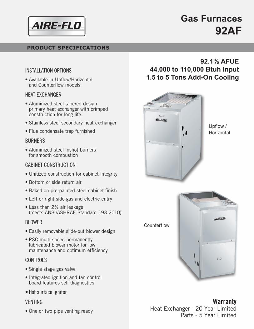
92.1% AFUE44,000 to 110,000 Btuh Input
1.5 to 5 Tons Add-On CoolingINSTALLATION OPTIONS
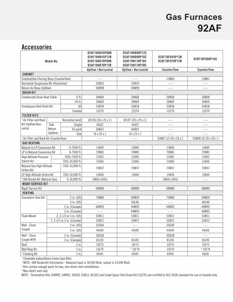
• Available in Upflow/Horizontal and Counterflow models
HEAT EXCHANGER
• Aluminized steel tapered design primary heat exchanger with crimped construction for long life
• Stainless steel secondary heat exchanger
• Flue condensate trap furnished
BURNERS
• Aluminized steel inshot burners for smooth combustion
CABINET CONSTRUCTION
• Unitized construction for cabinet integrity
• Bottom or side return air
• Baked on pre-painted steel cabinet finish
• Left or right side gas and electric entry
• Less than 2% air leakage (meets ANSI/ASHRAE Standard 193-2010)
BLOWER
• Easily removable slide-out blower design
• PSC multi-speed permanently lubricated blower motor for low maintenance and optimum efficiency
CONTROLS
• Single stage gas valve
• Integrated ignition and fan control board features self diagnostics
• Hot surface ignitor
VENTING
• One or two pipe venting ready
Warranty Heat Exchanger - 20 Year Limited
Parts - 5 Year Limited
PRODUCT SPECIFICATIONS
Upflow /Horizontal
Counterflow

Gas Furnaces92AF
SpecificationsModel No.
92AF1UH045P08B 92AF1UH045P12B 92AF1UH070P08B 92AF1UH070P12B 92AF1UH090P12C 92AF1UH090P16C
Upflow / Horiz. Upflow / Horiz. Upflow / Horiz. Upflow / Horiz. Upflow / Horiz. Upflow / Horiz.Input Btuh 44,000 44,000 66,000 66,000 88,000 88,000Output Btuh 41,000 42,000 62,000 62,000 83,000 83,000AFUE (Isolated Comb. System)
92.1% 92.1% 92.1% 92.1% 92.1% 92.1%
Temperature Rise (°F) 35 - 65 25 - 55 50 - 80 40 - 70 50 - 80 40 - 70Gas Pipe Size (in.) 1/2 1/2 1/2 1/2 1/2 1/2Inlet/Vent Connection in. (diameter)
2 2 2 2 2 2
Volts/Hertz/Phase 120/60/1 120/60/1 120/60/1 120/60/1 120/60/1 120/60/1Blower Motor Horsepower 1/5 1/3 1/5 1/3 1/3 1/2Add-On Cooling (tons) 1.5-2 2.5-3 1.5-2 2.5-3 2-3 3-4Circuit Breaker or Fuse 15 15 15 15 15 15Full Load Amps 3.1 6.1 3.1 6.1 6.1 8.2Blower Wheel Size (Dia. x Width)
10 x 8 10 x 8 10 x 8 10 x 8 10 x 8 10 x 10
Shipping Weight (lbs.) 120 122 125 127 143 146
Model Number Identification92 AF 1 UH 045 P 08 B
UH = Upflow / HorizontalDF = Counterflow
P = PSC Direct Drive Blower Motor
Nominal Airflow08 = 800 cfm12 = 1200 cfm16 = 1600 cfm20 = 2000 cfm
92 = AFUEAF = Aire-Flo
Heat Input045 = 45,000 Btuh070 = 70,000 Btuh090 = 90,000 Btuh
110 = 110,000 Btuh
1 = 1-Stage
Cabinet WidthB = 17-1/2 in.C = 21 in.
Model No.92AF1UH110P16C 92AF1UH110P20C 92AF1DF045P12B 92AF1DF070P12B 92AF1DF090P16C
Upflow / Horiz. Upflow / Horiz. Counterflow Counterflow CounterflowInput Btuh 110,000 110,000 44,000 66,000 88,000Output Btuh 104,000 104,000 42,000 62,000 84,000AFUE (Isolated Comb. System)
92.1% 92.1% 92.1% 92.1% 92.1%
Temperature Rise (°F) 50 - 80 40 - 70 25 - 55 50 - 80 40 - 70Gas Pipe Size (in.) 1/2 1/2 1/2 1/2 1/2Inlet/Vent Connection in. (diameter)
2 2 2 2 2
Volts/Hertz/Phase 120/60/1 120/60/1 120/60/1 120/60/1 120/60/1Blower Motor Horsepower 1/2 1 1/3 1/3 1/2Add-On Cooling (tons) 4 4-5 2.5-3 2.5-3 3-4Circuit Breaker or Fuse 15 15 15 15 15Full Load Amps 8.2 11.5 6.1 6.1 8.2Blower Wheel Size (Dia. x Width)
10 x 10 11 ½ x 10 10 x 8 10 x 8 10 x 10
Shipping Weight (lbs.) 155 161 124 129 147
Gas Furnaces92AF
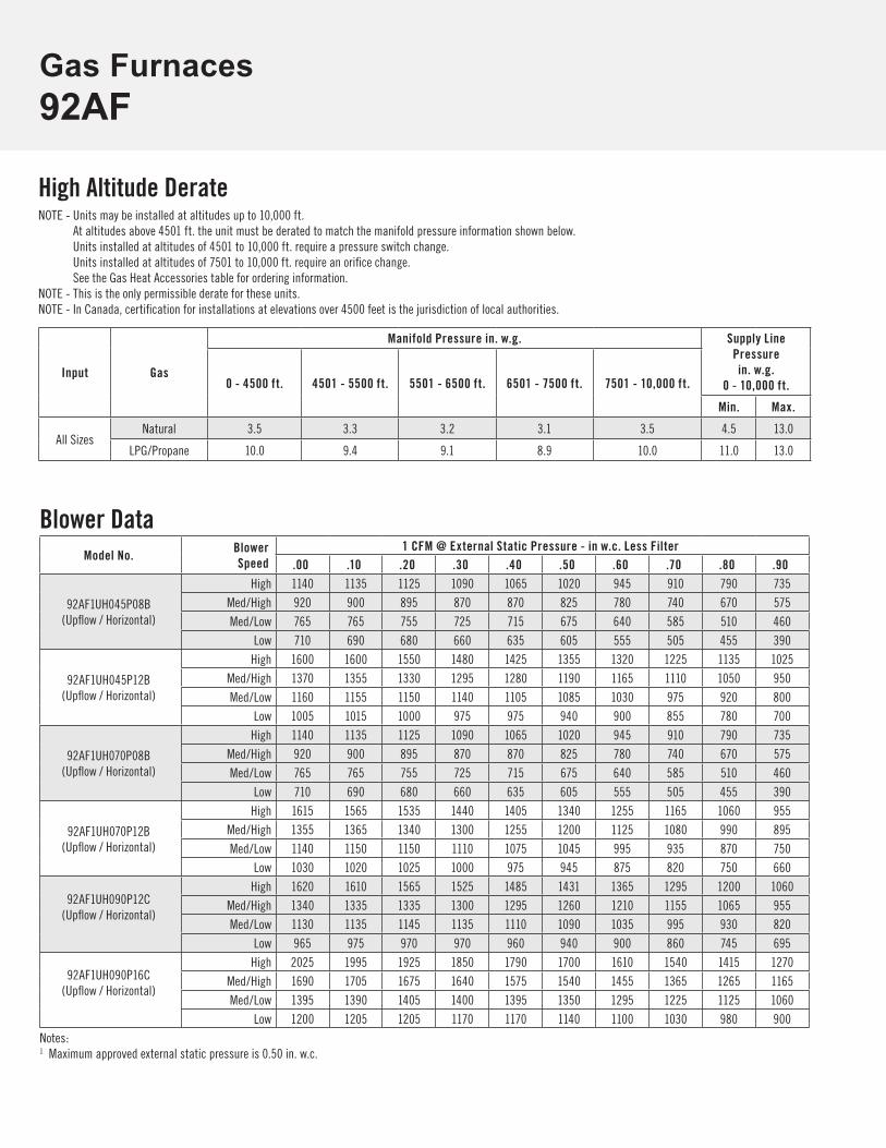
Accessories
Model No.
92AF1UH045P08B92AF1UH045P12B92AF1UH070P08B92AF1UH070P12B
92AF1UH090P12C92AF1UH090P16C92AF1UH110P16C92AF1UH110P20C
92AF1DF045P12B92AF1DF070P12B
92AF1DF090P16C
Upflow / Horizontal Upflow / Horizontal Counterflow CounterflowCABINET
Combustible Flooring Base (Counterflow) - - - - - - 11M60 11M61Horizontal Suspension Kit (Horizontal) 51W10 51W10 - - - - - -Return Air Base (Upflow) 50W98 50W99 - - - - - -DRAIN KIT
Condensate Drain Heat Cable 6 ft. 26K68 26K68 26K68 26K6824 ft. 26K69 26K69 26K69 26K69
Crawlspace Vent Drain Kit US 51W18 51W18 51W18 51W18Canada 15Z70 15Z70 15Z70 15Z70
FILTER KITS1 Air Filter and Rack Kit (Upflow/Hori-zontal
Horizontal (end) 87L96 (18 x 25 x 1) 87L97 (20 x 25 x 1) - - - - - - Side Return(Upflow)
Single 44J22 44J22 - - - - - -10-pack 66K63 66K63 - - - - - -
Size 16 x 25 x 1 16 x 25 x 1 - - - - - -1 Air Filter and Rack Kit (Counterflow) - - - - - - 51W07 (2) 20 x 20 x 1 51W08 (2) 20 x 20 x 1GAS HEATING
Natural to LP Conversion Kit 0-7500 ft. 11K49 11K49 11K49 11K49LP to Natural Conversion Kit 0-7500 ft. 73W81 73W81 73W81 73W81High Altitude Pressure Switch Kit
4501-7500 ft. 11U65 11U65 11U65 11U657501-10,000 ft. 11U66 11U66 11U66 11U66
Natural Gas High Altitude Orifice Kit
7501-10,000 ft.73W37 73W37 73W37 73W37
LP High Altitude Orifice Kit 7501-10,000 ft. 11K44 11K44 11K44 11K442 36K Derate Kit (Natural Gas) 0-10,000 ft. 10K55 (045) - - - 10K55 (045) - - -NIGHT SERVICE KIT
Night Service Kit 68W80 68W80 68W80 68W80VENTING
Concentric Vent Kit 2 in. (US) 71M80 69M29 71M80 69M293 in. (US) - - - 60L46 - - - 60L46
2 in. (Canada) 44W92 44W92 44W92 44W923 in. (Canada) - - - 44W93 - - - 44W93
Flush Mount 2, 2-1/2 or 3 in. (US) 51W11 51W11 51W11 51W112, 2-1/2 or 3 in. (Canada) 51W12 51W12 51W12 51W12
Wall - Close Couple
2 in. (US) 22G44 - - - 22G44 - - -
3 in. (US) 44J40 44J40 44J40 44J40
Wall - Close Couple WTK
2 in. (Canada) 30G28 - - - 30G28 - - -3 in. (Canada) 81J20 81J20 81J20 81J20
Roof 2 in. 15F75 15F75 15F75 15F75Wall Ring Kit 2 in. 15F74 4 15F74 15F74 4 15F743 Flashing Kit 2 in. 44J41 44J41 44J41 44J411 Cleanable polyurethane frame type filter. 2 NOTE: 36K Derate Kit Information - Reduced Input is 36,000 Btuh, output is 33,000 Btuh. 3 Kits contain enough parts for two, non-direct vent installations.4 Non-direct vent only.NOTE - Termination Kits (44W92, 44W93, 30G28, 51W12, 81J20) and Crawl Space Vent Drain Kit (15Z70) are certified to ULC S636 standard for use in Canada only.
Gas Furnaces92AF
Blower DataModel No. Blower
Speed1 CFM @ External Static Pressure - in w.c. Less Filter
.00 .10 .20 .30 .40 .50 .60 .70 .80 .90
92AF1UH045P08B(Upflow / Horizontal)
High 1140 1135 1125 1090 1065 1020 945 910 790 735Med/High 920 900 895 870 870 825 780 740 670 575Med/Low 765 765 755 725 715 675 640 585 510 460
Low 710 690 680 660 635 605 555 505 455 390
92AF1UH045P12B(Upflow / Horizontal)
High 1600 1600 1550 1480 1425 1355 1320 1225 1135 1025Med/High 1370 1355 1330 1295 1280 1190 1165 1110 1050 950Med/Low 1160 1155 1150 1140 1105 1085 1030 975 920 800
Low 1005 1015 1000 975 975 940 900 855 780 700
92AF1UH070P08B(Upflow / Horizontal)
High 1140 1135 1125 1090 1065 1020 945 910 790 735Med/High 920 900 895 870 870 825 780 740 670 575Med/Low 765 765 755 725 715 675 640 585 510 460
Low 710 690 680 660 635 605 555 505 455 390
92AF1UH070P12B(Upflow / Horizontal)
High 1615 1565 1535 1440 1405 1340 1255 1165 1060 955Med/High 1355 1365 1340 1300 1255 1200 1125 1080 990 895Med/Low 1140 1150 1150 1110 1075 1045 995 935 870 750
Low 1030 1020 1025 1000 975 945 875 820 750 660
92AF1UH090P12C(Upflow / Horizontal)
High 1620 1610 1565 1525 1485 1431 1365 1295 1200 1060Med/High 1340 1335 1335 1300 1295 1260 1210 1155 1065 955Med/Low 1130 1135 1145 1135 1110 1090 1035 995 930 820
Low 965 975 970 970 960 940 900 860 745 695
92AF1UH090P16C(Upflow / Horizontal)
High 2025 1995 1925 1850 1790 1700 1610 1540 1415 1270Med/High 1690 1705 1675 1640 1575 1540 1455 1365 1265 1165Med/Low 1395 1390 1405 1400 1395 1350 1295 1225 1125 1060
Low 1200 1205 1205 1170 1170 1140 1100 1030 980 900Notes:1 Maximum approved external static pressure is 0.50 in. w.c.
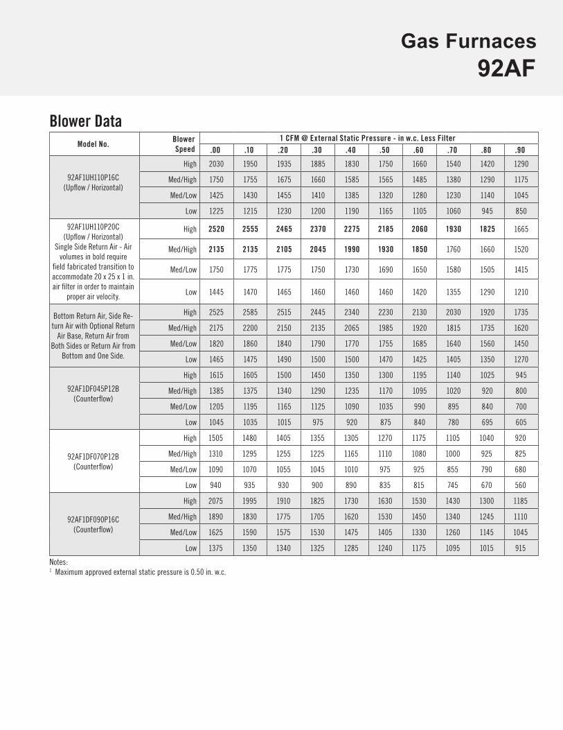
High Altitude DerateNOTE - Units may be installed at altitudes up to 10,000 ft.
At altitudes above 4501 ft. the unit must be derated to match the manifold pressure information shown below. Units installed at altitudes of 4501 to 10,000 ft. require a pressure switch change. Units installed at altitudes of 7501 to 10,000 ft. require an orifice change. See the Gas Heat Accessories table for ordering information.
NOTE - This is the only permissible derate for these units. NOTE - In Canada, certification for installations at elevations over 4500 feet is the jurisdiction of local authorities.
Input Gas
Manifold Pressure in. w.g. Supply Line Pressure in. w.g.
0 - 10,000 ft.0 - 4500 ft. 4501 - 5500 ft. 5501 - 6500 ft. 6501 - 7500 ft. 7501 - 10,000 ft.
Min. Max.
All SizesNatural 3.5 3.3 3.2 3.1 3.5 4.5 13.0
LPG/Propane 10.0 9.4 9.1 8.9 10.0 11.0 13.0
Gas Furnaces92AF
Blower DataModel No.
Blower Speed
1 CFM @ External Static Pressure - in w.c. Less Filter.00 .10 .20 .30 .40 .50 .60 .70 .80 .90
92AF1UH110P16C(Upflow / Horizontal)
High 2030 1950 1935 1885 1830 1750 1660 1540 1420 1290
Med/High 1750 1755 1675 1660 1585 1565 1485 1380 1290 1175
Med/Low 1425 1430 1455 1410 1385 1320 1280 1230 1140 1045
Low 1225 1215 1230 1200 1190 1165 1105 1060 945 850
92AF1UH110P20C(Upflow / Horizontal)
Single Side Return Air - Air volumes in bold require
field fabricated transition to accommodate 20 x 25 x 1 in. air filter in order to maintain
proper air velocity.
High 2520 2555 2465 2370 2275 2185 2060 1930 1825 1665
Med/High 2135 2135 2105 2045 1990 1930 1850 1760 1660 1520
Med/Low 1750 1775 1775 1750 1730 1690 1650 1580 1505 1415
Low 1445 1470 1465 1460 1460 1460 1420 1355 1290 1210
Bottom Return Air, Side Re-turn Air with Optional Return
Air Base, Return Air from Both Sides or Return Air from
Bottom and One Side.
High 2525 2585 2515 2445 2340 2230 2130 2030 1920 1735
Med/High 2175 2200 2150 2135 2065 1985 1920 1815 1735 1620
Med/Low 1820 1860 1840 1790 1770 1755 1685 1640 1560 1450
Low 1465 1475 1490 1500 1500 1470 1425 1405 1350 1270
92AF1DF045P12B(Counterflow)
High 1615 1605 1500 1450 1350 1300 1195 1140 1025 945
Med/High 1385 1375 1340 1290 1235 1170 1095 1020 920 800
Med/Low 1205 1195 1165 1125 1090 1035 990 895 840 700
Low 1045 1035 1015 975 920 875 840 780 695 605
92AF1DF070P12B(Counterflow)
High 1505 1480 1405 1355 1305 1270 1175 1105 1040 920
Med/High 1310 1295 1255 1225 1165 1110 1080 1000 925 825
Med/Low 1090 1070 1055 1045 1010 975 925 855 790 680
Low 940 935 930 900 890 835 815 745 670 560
92AF1DF090P16C(Counterflow)
High 2075 1995 1910 1825 1730 1630 1530 1430 1300 1185
Med/High 1890 1830 1775 1705 1620 1530 1450 1340 1245 1110
Med/Low 1625 1590 1575 1530 1475 1405 1330 1260 1145 1045
Low 1375 1350 1340 1325 1285 1240 1175 1095 1015 915
Notes:1 Maximum approved external static pressure is 0.50 in. w.c.
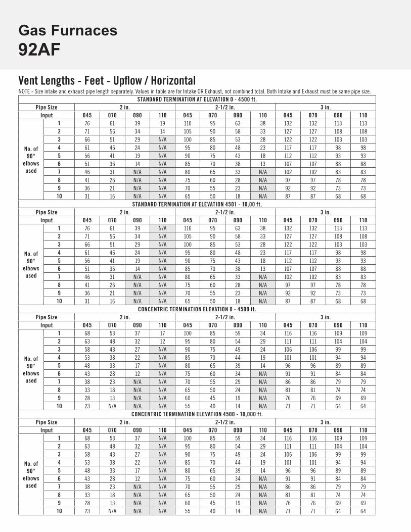
Gas Furnaces92AFVent Lengths - Feet - Upflow / HorizontalNOTE - Size intake and exhaust pipe length separately. Values in table are for Intake OR Exhaust, not combined total. Both Intake and Exhaust must be same pipe size.
STANDARD TERMINATION AT ELEVATION 0 - 4500 ft.Pipe Size 2 in. 2-1/2 in. 3 in.
Input 045 070 090 110 045 070 090 110 045 070 090 110
No. of 90°
elbowsused
1 76 61 39 19 110 95 63 38 132 132 113 1132 71 56 34 14 105 90 58 33 127 127 108 1083 66 51 29 N/A 100 85 53 28 122 122 103 1034 61 46 24 N/A 95 80 48 23 117 117 98 985 56 41 19 N/A 90 75 43 18 112 112 93 936 51 36 14 N/A 85 70 38 13 107 107 88 887 46 31 N/A N/A 80 65 33 N/A 102 102 83 838 41 26 N/A N/A 75 60 28 N/A 97 97 78 789 36 21 N/A N/A 70 55 23 N/A 92 92 73 7310 31 16 N/A N/A 65 50 18 N/A 87 87 68 68
STANDARD TERMINATION AT ELEVATION 4501 - 10,00 ft.Pipe Size 2 in. 2-1/2 in. 3 in.
Input 045 070 090 110 045 070 090 110 045 070 090 110
No. of 90°
elbowsused
1 76 61 39 N/A 110 95 63 38 132 132 113 1132 71 56 34 N/A 105 90 58 33 127 127 108 1083 66 51 29 N/A 100 85 53 28 122 122 103 1034 61 46 24 N/A 95 80 48 23 117 117 98 985 56 41 19 N/A 90 75 43 18 112 112 93 936 51 36 14 N/A 85 70 38 13 107 107 88 887 46 31 N/A N/A 80 65 33 N/A 102 102 83 838 41 26 N/A N/A 75 60 28 N/A 97 97 78 789 36 21 N/A N/A 70 55 23 N/A 92 92 73 7310 31 16 N/A N/A 65 50 18 N/A 87 87 68 68
CONCENTRIC TERMINATION ELEVATION 0 - 4500 ft.Pipe Size 2 in. 2-1/2 in. 3 in.
Input 045 070 090 110 045 070 090 110 045 070 090 110
No. of 90°
elbowsused
1 68 53 37 17 100 85 59 34 116 116 109 1092 63 48 32 12 95 80 54 29 111 111 104 1043 58 43 27 N/A 90 75 49 24 106 106 99 994 53 38 22 N/A 85 70 44 19 101 101 94 945 48 33 17 N/A 80 65 39 14 96 96 89 896 43 28 12 N/A 75 60 34 N/A 91 91 84 847 38 23 N/A N/A 70 55 29 N/A 86 86 79 798 33 18 N/A N/A 65 50 24 N/A 81 81 74 749 28 13 N/A N/A 60 45 19 N/A 76 76 69 6910 23 N/A N/A N/A 55 40 14 N/A 71 71 64 64
CONCENTRIC TERMINATION ELEVATION 4500 - 10,000 ft.Pipe Size 2 in. 2-1/2 in. 3 in.
Input 045 070 090 110 045 070 090 110 045 070 090 110
No. of 90°
elbowsused
1 68 53 37 N/A 100 85 59 34 116 116 109 1092 63 48 32 N/A 95 80 54 29 111 111 104 1043 58 43 27 N/A 90 75 49 24 106 106 99 994 53 38 22 N/A 85 70 44 19 101 101 94 945 48 33 17 N/A 80 65 39 14 96 96 89 896 43 28 12 N/A 75 60 34 N/A 91 91 84 847 38 23 N/A N/A 70 55 29 N/A 86 86 79 798 33 18 N/A N/A 65 50 24 N/A 81 81 74 749 28 13 N/A N/A 60 45 19 N/A 76 76 69 6910 23 N/A N/A N/A 55 40 14 N/A 71 71 64 64
Gas Furnaces92AF
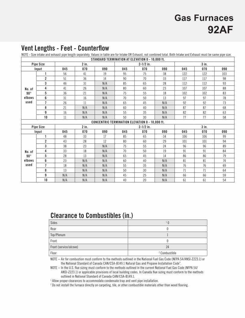
Vent Lengths - Feet - CounterflowNOTE - Size intake and exhaust pipe length separately. Values in table are for Intake OR Exhaust, not combined total. Both Intake and Exhaust must be same pipe size.
STANDARD TERMINATION AT ELEVATION 0 - 10,000 ft.Pipe Size 2 in. 2-1/2 in. 3 in.
Input 045 070 090 045 070 090 045 070 090
No. of 90°
elbowsused
1 56 41 19 95 75 38 122 122 1032 51 36 14 90 70 33 117 117 983 46 31 N/A 85 65 28 112 112 934 41 26 N/A 80 60 23 107 107 885 36 21 N/A 75 55 18 102 102 836 31 16 N/A 70 50 13 97 97 787 26 11 N/A 65 45 N/A 92 92 738 21 N/A N/A 60 40 N/A 87 87 689 16 N/A N/A 55 35 N/A 82 82 6310 11 N/A N/A 50 30 N/A 77 77 58
CONCENTRIC TERMINATION ELEVATION 0 - 10,000 ft.Pipe Size 2 in. 2-1/2 in. 3 in.
Input 045 070 090 045 070 090 045 070 090
No. of 90°
elbowsused
1 48 33 17 85 65 34 106 106 992 43 28 12 80 60 29 101 101 943 38 23 N/A 75 55 24 96 96 894 33 18 N/A 70 50 19 91 91 845 28 13 N/A 65 45 14 86 86 796 23 N/A N/A 60 40 N/A 81 81 747 18 N/A N/A 55 35 N/A 76 76 698 13 N/A N/A 50 30 N/A 71 71 649 N/A N/A N/A 45 25 N/A 66 66 5910 N/A N/A N/A 40 20 N/A 61 61 54
Clearance to Combustibles (in.)Sides 1 0
Rear 0
Top/Plenum 1
Front 0
Front (service/alcove) 24
Floor 2 Combustible
NOTE − Air for combustion must conform to the methods outlined in the National Fuel Gas Code (NFPA 54/ANSI-Z223.1) or the National Standard of Canada CAN/CSA-B149.1 Natural Gas and Propane Installation Code”.
NOTE − In the U.S. flue sizing must conform to the methods outlined in the current National Fuel Gas Code (NFPA 54/ANSI-Z223.1) or applicable provisions of local building codes. In Canada flue sizing must conform to the methods outlined in National Standard of Canada CAN/CSA-B149.1.
1 Allow proper clearances to accommodate condensate trap and vent pipe installation.2 Do not install the furnace directly on carpeting, tile, or other combustible materials other than wood flooring.
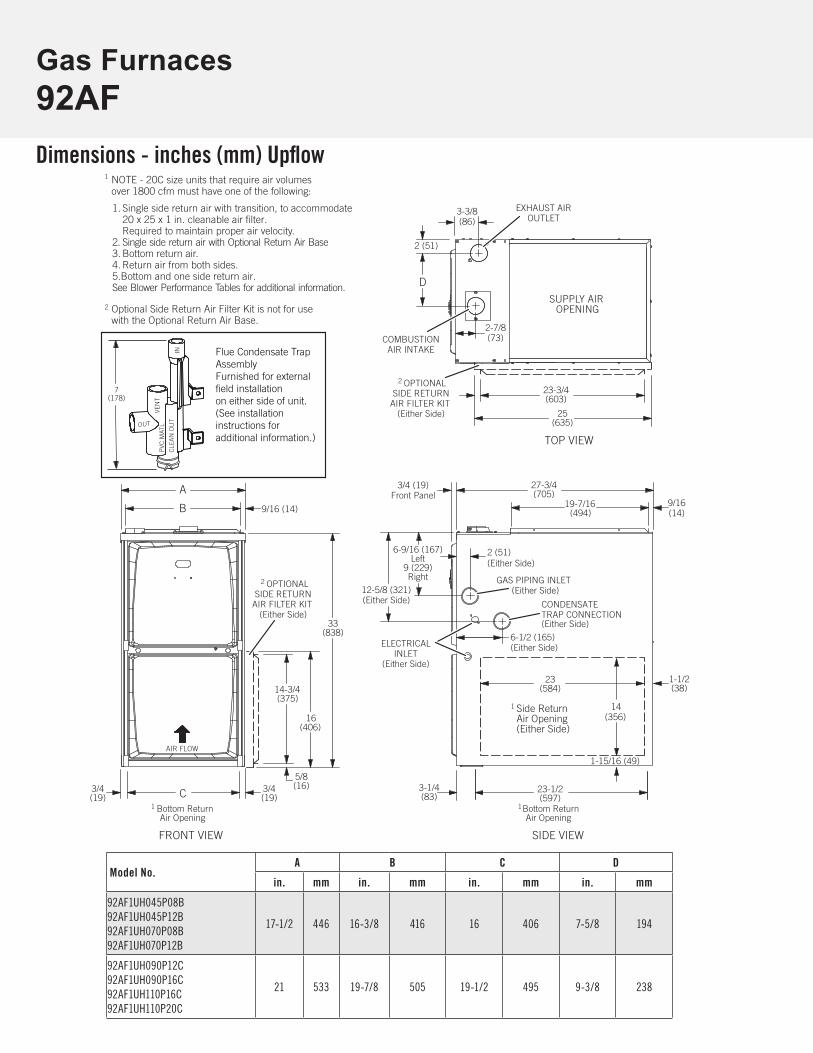
Gas Furnaces92AFDimensions - inches (mm) Upflow
Model No.A B C D
in. mm in. mm in. mm in. mm
92AF1UH045P08B92AF1UH045P12B92AF1UH070P08B92AF1UH070P12B
17-1/2 446 16-3/8 416 16 406 7-5/8 194
92AF1UH090P12C92AF1UH090P16C92AF1UH110P16C92AF1UH110P20C
21 533 19-7/8 505 19-1/2 495 9-3/8 238
6-9/16 (167)Left
9 (229)Right
23(584)
(19)3/4
(19)1 Bottom Return
Air Opening
GAS PIPING INLET(Either Side)
Side ReturnAir Opening(Either Side)
1 Bottom Return
Air Opening
EXHAUST AIROUTLET
ELECTRICALINLET
(Either Side)
SUPPLY AIROPENING
FRONT VIEW SIDE VIEW
TOP VIEW
A
B 9/16 (14)
C3/4
27-3/4(705)
19-7/16(494)
23-1/2(597)
1-1/2(38)
6-1/2 (165)(Either Side)
33(838)
3-3/8(86)
1-15/16 (49)
14(356)
9/16(14)
12-5/8 (321)(Either Side)
2 OPTIONALSIDE RETURN
AIR FILTER KIT(Either Side)
16(406)
14-3/4(375)
2 OPTIONALSIDE RETURN
AIR FILTER KIT(Either Side)
5/8(16)
1
3-1/4(83)
23-3/4(603)
25(635)
D
3/4 (19)Front Panel
COMBUSTIONAIR INTAKE
2 (51)(Either Side)
2 (51)
CONDENSATETRAP CONNECTION(Either Side)
2 Optional Side Return Air Filter Kit is not for usewith the Optional Return Air Base.
1 NOTE - 20C size units that require air volumes over 1800 cfm must have one of the following:
1. Single side return air with transition, to accommodate20 x 25 x 1 in. cleanable air filter.Required to maintain proper air velocity.
2. Single side return air with Optional Return Air Base3. Bottom return air.4. Return air from both sides.5.Bottom and one side return air.See Blower Performance Tables for additional information.
2-7/8(73)
AIR FLOW
Flue Condensate TrapAssemblyFurnished for externalfield installationon either side of unit.(See installationinstructions foradditional information.)
7(178)
OUT
VEN
T
CLE
AN
OU
T
PVC
MAT
L
IN

Gas Furnaces92AF
Model No.A B C D
in. mm in. mm in. mm in. mm
92AF1UH045P08B92AF1UH045P12B92AF1UH070P08B92AF1UH070P12B
17-1/2 446 16-3/8 416 16 406 7-5/8 194
92AF1UH090P12C92AF1UH090P16C92AF1UH110P16C92AF1UH110P20C
21 533 19-7/8 505 19-1/2 495 9-3/8 238
D
A
TOP VIEW
27-3/4(705)
33(838)
27-3/4(705)
27-3/4(705)
A
GAS PIPING INLET(Top or Bottom)
RETURNAIR
OPENING
ELECTRICAL INLET(Top or Bottom)
SUPPLYAIR
OPENING
FRONT VIEW
TOP VIEW
CA
END VIEWEND VIEW
33(838)
27-3/4(705)
19-7/16(494)
9/16(14)
B
23-1/2(591)
3-1/4(95)
(19)
2 (51)Top or Bottom
6-1/2 (165)Bottom
3-3/8 (86)
EXHAUST AIROUTLET
LEFT-HAND AIR DISCHARGE
FRONT VIEWEND VIEW END VIEW
AIRFLOW
ELECTRICAL INLET(Top or Bottom)
RIGHT-HAND AIR DISCHARGE
9/16(14)
3/4
AIRFLOW
AIRFLOW
19-7/16(494)
9/16(14)B
9/16(14)
DA
(86)3-3/8
SUPPLYAIR
OPENING
RETURNAIR
OPENING
C
23-1/2(591)
3-1/4(95)
(19)3/4
AIRFLOW
COMBUSTIONAIR INTAKE
EXHAUST AIROUTLET
COMBUSTIONAIR INTAKE
2 (51)
2 (51)
6-9/16 (167) Top9 (229) Bottom
12-5/8 (321)Bottom
CONDENSATETRAP CONNECTION
6-9/16 (167) Bottom9 (229) Top
12-5/8 (321)Bottom
2 (51)Top or Bottom
6-1/2 (165)Bottom
(Bottom)
GAS PIPING INLET(Top or Bottom)
CONDENSATETRAP CONNECTION
(Bottom)
3/4(19)
2-7/8(73)
2-7/8(73)
3/4(19)
3/4(19)
3/4(19)
3/4 (19)Front Panel
Dimensions - inches (mm) Horizontal
Gas Furnaces92AF
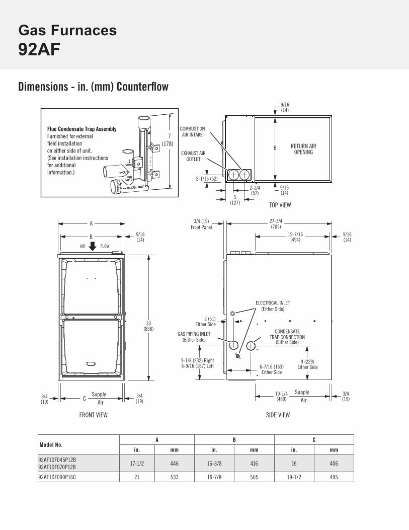
Dimensions - in. (mm) Counterflow
Model No.A B C
in. mm in. mm in. mm
92AF1DF045P12B92AF1DF070P12B
17-1/2 446 16-3/8 416 16 406
92AF1DF090P16C 21 533 19-7/8 505 19-1/2 495
AIR
EXHAUST AIROUTLET
COMBUSTIONAIR INTAKE
FLOW
2-1/16 (52)
GAS PIPING INLET(Either Side)
ELECTRICAL INLET(Either Side)
RETURN AIROPENING
FRONT VIEW SIDE VIEW
TOP VIEW
A
B
C 3/4(19)
27-3/4(705)
19-1/4(489)
9-1/8 (232) Right6-9/16 (167) Left
2 (51)Either Side33
(838)
3/4(19)
B
SupplyAir
SupplyAir
9/16(14)
9/16(14)
9/16(14)
9/16(14)
19-7/16(494)
3/4(19)
CONDENSATETRAP CONNECTION
5(127)
6-7/16 (163)Either Side
9 (229)Either Side
2-1/4(57)
(Either Side)
3/4 (19)Front Panel
Flue Condensate Trap AssemblyFurnished for externalfield installationon either side of unit.(See installation instructionsfor additionalinformation.)
7(178)
Gas Furnaces92AF


Gas Furnaces92AF
1.800.982.2333 www.aireflo-hvac.com 210597 (11/17) © Aire-Flo Heating and Cooling, 2017
RevisionsSections Description of Change
Accessories Updated LP High Altitude Orifice Kit catalog numbers for all units.