product specification, next generation instrumentation … reference documents 1.5.1 test...
TRANSCRIPT

Product Specification,Next Generation
Instrumentation (NGI™)
072-40337-A

Every effort has been made to keep the information in this document current and ac-curate as of the date of publication or revision. However, no guarantee is given orimplied that the document is error-free or that it is accurate with regard to any speci-fication. AMETEK Dixson reserves the right to modify product designs and specifica-tions without notice.
Free telephone assistance is available Monday through Friday from 7 a.m. to 4:30 p.m.
AMETEK Dixson Product Management Department287 27 Road, Grand Junction, CO 81503Phone: (970) 244-1241Toll-Free: (888) 302-0639E-Mail: [email protected]
072-40337 Revision Table
REVISION DATE DESCRIPTION OF CHANGE
- 12/18/2002 Initial release
A 10/28/2003 Update and enhance all chapters
ii 072-40337-A

NGI Product Specification
072-40337-A iii
Table of Contents
1 Introduction Page 1-11.1 Purpose and Scope . . . . . . . . . . . . . . . . . . . . . . . . . 1-11.2 Options and Deviations from Generic Product . . . . . . . . . . . . . . . . . 1-11.3 Overview . . . . . . . . . . . . . . . . . . . . . . . . . . . . 1-11.4 How to Use This Specification . . . . . . . . . . . . . . . . . . . . . 1-11.5 Reference Documents . . . . . . . . . . . . . . . . . . . . . . . . 1-2
1.5.1 Test Specifications. . . . . . . . . . . . . . . . . . . . . . . . . . . . . . . . . . . . . . . . . . . . . . . . . . . . . . . . . . 1-21.5.2 Interface Specifications . . . . . . . . . . . . . . . . . . . . . . . . . . . . . . . . . . . . . . . . . . . . . . . . . . . . . . 1-2
1.6 Regulatory Agencies . . . . . . . . . . . . . . . . . . . . . . . . 1-21.7 Abbreviations and Terminology in This Document . . . . . . . . . . . . . . . 1-3
2 Functional Description Page 2-12.1 Vehicle Data Bus . . . . . . . . . . . . . . . . . . . . . . . . . 2-22.2 NGI Bus . . . . . . . . . . . . . . . . . . . . . . . . . . . . 2-22.3 NGI Cable Assemblies . . . . . . . . . . . . . . . . . . . . . . . . 2-22.4 System Control Unit (SCU) . . . . . . . . . . . . . . . . . . . . . . 2-2
2.4.1 SCU Inputs . . . . . . . . . . . . . . . . . . . . . . . . . . . . . . . . . . . . . . . . . . . . . . . . . . . . . . . . . . . . . . . . 2-22.4.2 SCU Options. . . . . . . . . . . . . . . . . . . . . . . . . . . . . . . . . . . . . . . . . . . . . . . . . . . . . . . . . . . . . . . 2-2
2.5 Speedometer . . . . . . . . . . . . . . . . . . . . . . . . . . . 2-32.5.1 Speedometer Options. . . . . . . . . . . . . . . . . . . . . . . . . . . . . . . . . . . . . . . . . . . . . . . . . . . . . . . . 2-32.5.2 Audible Warning Device. . . . . . . . . . . . . . . . . . . . . . . . . . . . . . . . . . . . . . . . . . . . . . . . . . . . . . 2-3
2.5.2.1 Buzzer Options..............................................................................................................2-32.5.3 Mode and Set Switches. . . . . . . . . . . . . . . . . . . . . . . . . . . . . . . . . . . . . . . . . . . . . . . . . . . . . . 2-3
2.5.3.1 Mode/Set Switch Options ............................................................................................2-32.5.4 Alphanumeric Display . . . . . . . . . . . . . . . . . . . . . . . . . . . . . . . . . . . . . . . . . . . . . . . . . . . . . . . 2-4
2.6 Electrical Gauges . . . . . . . . . . . . . . . . . . . . . . . . . 2-42.7 Mechanical Air Pressure Gauges. . . . . . . . . . . . . . . . . . . . . 2-42.8 Light Bars . . . . . . . . . . . . . . . . . . . . . . . . . . . . 2-5
2.8.1 Standard Light Bar . . . . . . . . . . . . . . . . . . . . . . . . . . . . . . . . . . . . . . . . . . . . . . . . . . . . . . . . . . 2-52.8.2 Light Bar Options . . . . . . . . . . . . . . . . . . . . . . . . . . . . . . . . . . . . . . . . . . . . . . . . . . . . . . . . . . . 2-5
2.9 Calibration and Diagnostic Capabilities . . . . . . . . . . . . . . . . . . . 2-52.9.1 Calibration . . . . . . . . . . . . . . . . . . . . . . . . . . . . . . . . . . . . . . . . . . . . . . . . . . . . . . . . . . . . . . . . 2-52.9.2 System Diagnostics . . . . . . . . . . . . . . . . . . . . . . . . . . . . . . . . . . . . . . . . . . . . . . . . . . . . . . . . . 2-52.9.3 Additional Fault Indications . . . . . . . . . . . . . . . . . . . . . . . . . . . . . . . . . . . . . . . . . . . . . . . . . . . 2-5
3 Module Specifications Page 3-13.1 General Information . . . . . . . . . . . . . . . . . . . . . . . . . 3-1
3.1.1 Dial Configurations . . . . . . . . . . . . . . . . . . . . . . . . . . . . . . . . . . . . . . . . . . . . . . . . . . . . . . . . . . 3-13.1.2 Parameters Common to All Modules . . . . . . . . . . . . . . . . . . . . . . . . . . . . . . . . . . . . . . . . . . . . 3-1
3.1.2.1 Case Construction, Mounting, and Connectors ............................................................3-13.1.2.2 Dials and Graphics........................................................................................................3-1
3.1.3 Pointers . . . . . . . . . . . . . . . . . . . . . . . . . . . . . . . . . . . . . . . . . . . . . . . . . . . . . . . . . . . . . . . . . . 3-13.1.4 Gauge Warning LEDs . . . . . . . . . . . . . . . . . . . . . . . . . . . . . . . . . . . . . . . . . . . . . . . . . . . . . . . . 3-2

iv 072-40337-A
3.1.5 Automatic Pointer Re-Zero. . . . . . . . . . . . . . . . . . . . . . . . . . . . . . . . . . . . . . . . . . . . . . . . . . . . . . 3-23.1.6 Loss-of-Data Indication . . . . . . . . . . . . . . . . . . . . . . . . . . . . . . . . . . . . . . . . . . . . . . . . . . . . . . . . 3-23.1.7 Data Out-Of-Range Indication. . . . . . . . . . . . . . . . . . . . . . . . . . . . . . . . . . . . . . . . . . . . . . . . . . . . 3-23.1.8 Analog Input Filtering. . . . . . . . . . . . . . . . . . . . . . . . . . . . . . . . . . . . . . . . . . . . . . . . . . . . . . . . . . 3-23.1.9 Customer Specifications . . . . . . . . . . . . . . . . . . . . . . . . . . . . . . . . . . . . . . . . . . . . . . . . . . . . . . . 3-33.1.10 Gauge Options . . . . . . . . . . . . . . . . . . . . . . . . . . . . . . . . . . . . . . . . . . . . . . . . . . . . . . . . . . . . . . 3-3
3.2 Available Modules . . . . . . . . . . . . . . . . . . . . . . . . . . 3-53.2.1 Speedometers . . . . . . . . . . . . . . . . . . . . . . . . . . . . . . . . . . . . . . . . . . . . . . . . . . . . . . . . . . . . . . . 3-53.2.2 Tachometers . . . . . . . . . . . . . . . . . . . . . . . . . . . . . . . . . . . . . . . . . . . . . . . . . . . . . . . . . . . . . . . . 3-53.2.3 Pressure Gauges . . . . . . . . . . . . . . . . . . . . . . . . . . . . . . . . . . . . . . . . . . . . . . . . . . . . . . . . . . . . . 3-53.2.4 Temperature Gauges . . . . . . . . . . . . . . . . . . . . . . . . . . . . . . . . . . . . . . . . . . . . . . . . . . . . . . . . . . 3-53.2.5 Fuel Level Gauge . . . . . . . . . . . . . . . . . . . . . . . . . . . . . . . . . . . . . . . . . . . . . . . . . . . . . . . . . . . . . 3-63.2.6 Voltmeters and Ammeters . . . . . . . . . . . . . . . . . . . . . . . . . . . . . . . . . . . . . . . . . . . . . . . . . . . . . . 3-63.2.7 Ammeters . . . . . . . . . . . . . . . . . . . . . . . . . . . . . . . . . . . . . . . . . . . . . . . . . . . . . . . . . . . . . . . . . . 3-63.2.8 Multiple Display Modules . . . . . . . . . . . . . . . . . . . . . . . . . . . . . . . . . . . . . . . . . . . . . . . . . . . . . . 3-63.2.9 Light Bars . . . . . . . . . . . . . . . . . . . . . . . . . . . . . . . . . . . . . . . . . . . . . . . . . . . . . . . . . . . . . . . . . 3-143.2.10 Telltale Control . . . . . . . . . . . . . . . . . . . . . . . . . . . . . . . . . . . . . . . . . . . . . . . . . . . . . . . . . . . . . 3-14
3.3 Alphanumeric Display . . . . . . . . . . . . . . . . . . . . . . . . 3-153.3.1 Default Display or Function . . . . . . . . . . . . . . . . . . . . . . . . . . . . . . . . . . . . . . . . . . . . . . . . . . . . 3-16
3.3.1.1 User-Defined Default Function ......................................................................................3-163.3.1.2 Persistency Option .......................................................................................................3-16
3.3.2 Custom Messages . . . . . . . . . . . . . . . . . . . . . . . . . . . . . . . . . . . . . . . . . . . . . . . . . . . . . . . . . . . 3-163.3.3 Odometer Display and Function . . . . . . . . . . . . . . . . . . . . . . . . . . . . . . . . . . . . . . . . . . . . . . . . . 3-163.3.4 Independent Trip Odometer Display and Function . . . . . . . . . . . . . . . . . . . . . . . . . . . . . . . . . . . 3-173.3.5 Hourmeter Display and Function . . . . . . . . . . . . . . . . . . . . . . . . . . . . . . . . . . . . . . . . . . . . . . . . 3-173.3.6 Other Functions . . . . . . . . . . . . . . . . . . . . . . . . . . . . . . . . . . . . . . . . . . . . . . . . . . . . . . . . . . . . . 3-18
3.3.6.1 User-Initiated Diagnostic Function................................................................................3-183.3.6.2 Manual Test..................................................................................................................3-193.3.6.3 Fault Messages ............................................................................................................3-193.3.6.4 NGI Warning Messages................................................................................................3-19
3.3.7 Alphanumeric Display Backlighting. . . . . . . . . . . . . . . . . . . . . . . . . . . . . . . . . . . . . . . . . . . . . . 3-223.4 Audible Warning Device (Buzzer) . . . . . . . . . . . . . . . . . . . . . 3-22
3.4.1 Customer-Specified Information for Alphanumeric Display and Buzzer . . . . . . . . . . . . . . . . . . . 3-223.5 System Operation. . . . . . . . . . . . . . . . . . . . . . . . . . 3-22
3.5.1 Power-On Initialization Sequence. . . . . . . . . . . . . . . . . . . . . . . . . . . . . . . . . . . . . . . . . . . . . . . . 3-22
4 Electrical Specifications Page 4-14.1 General Panel Wiring . . . . . . . . . . . . . . . . . . . . . . . . . 4-14.2 Speedometer/SCU Connections . . . . . . . . . . . . . . . . . . . . . . 4-24.3 Light Bar Connections . . . . . . . . . . . . . . . . . . . . . . . . . 4-3
5 Mounting Specifications Page 5-1
6 Environmental and Reliability Specifications Page 6-16.1 Environmental Specifications . . . . . . . . . . . . . . . . . . . . . . 6-16.2 Reliability Specifications . . . . . . . . . . . . . . . . . . . . . . . . 6-1
6.2.1 Reliability . . . . . . . . . . . . . . . . . . . . . . . . . . . . . . . . . . . . . . . . . . . . . . . . . . . . . . . . . . . . . . . . . . . 6-16.3 Serviceability . . . . . . . . . . . . . . . . . . . . . . . . . . . 6-2

NGI Product Specification
072-40337-A v
List of TablesTable 3-1 Examples of NGI Warning Messages · · · · · · · · · · · · · · · · · · · · · · · · · · · · · · 3-20Table 3-2 Message Priorities · · · · · · · · · · · · · · · · · · · · · · · · · · · · · · · · · · · · · · · · 3-21Table 4-1 Electrical Specifications · · · · · · · · · · · · · · · · · · · · · · · · · · · · · · · · · · · · · · 4-3Table 6-1 Environmental Specifications · · · · · · · · · · · · · · · · · · · · · · · · · · · · · · · · · · · 6-1Table 6-2 Reliability Specifications · · · · · · · · · · · · · · · · · · · · · · · · · · · · · · · · · · · · · 6-1
List of IllustrationsFigure 2-1 Functional Block Diagram · · · · · · · · · · · · · · · · · · · · · · · · · · · · · · · · · · · · · 2-1Figure 2-2 Standard Alphanumeric Display Functions · · · · · · · · · · · · · · · · · · · · · · · · · · · · 2-4Figure 3-1 Gauge Options· · · · · · · · · · · · · · · · · · · · · · · · · · · · · · · · · · · · · · · · · · · 3-4Figure 3-2 Speedometer Dials · · · · · · · · · · · · · · · · · · · · · · · · · · · · · · · · · · · · · · · · 3-7Figure 3-3 Tachometer Dials · · · · · · · · · · · · · · · · · · · · · · · · · · · · · · · · · · · · · · · · · 3-8Figure 3-4 Five-Inch Combination Dials · · · · · · · · · · · · · · · · · · · · · · · · · · · · · · · · · · · · 3-8Figure 3-5 English Pressure Dials · · · · · · · · · · · · · · · · · · · · · · · · · · · · · · · · · · · · · · · 3-9Figure 3-6 Metric Pressure Dials · · · · · · · · · · · · · · · · · · · · · · · · · · · · · · · · · · · · · · 3-10Figure 3-7 Temperature Dials · · · · · · · · · · · · · · · · · · · · · · · · · · · · · · · · · · · · · · · · 3-11Figure 3-8 Other Standard Dials · · · · · · · · · · · · · · · · · · · · · · · · · · · · · · · · · · · · · · · 3-11Figure 3-9 Example Pressure Sensor Output Resistance Curve · · · · · · · · · · · · · · · · · · · · · · · 3-12Figure 3-10 Example Temperature Sender Curve · · · · · · · · · · · · · · · · · · · · · · · · · · · · · · · 3-12Figure 3-11 Example Resistance Curve from a Fuel Level Sensor · · · · · · · · · · · · · · · · · · · · · · 3-13Figure 3-12 Examples of Telltale and Light Bar Designs · · · · · · · · · · · · · · · · · · · · · · · · · · · 3-14Figure 3-13 Power-On Initialization Sequence · · · · · · · · · · · · · · · · · · · · · · · · · · · · · · · · 3-23Figure 3-14 Main Loop · · · · · · · · · · · · · · · · · · · · · · · · · · · · · · · · · · · · · · · · · · · · 3-24Figure 3-15 Diagnostic Test Loop· · · · · · · · · · · · · · · · · · · · · · · · · · · · · · · · · · · · · · · 3-25Figure 3-16 Manual Test Loop · · · · · · · · · · · · · · · · · · · · · · · · · · · · · · · · · · · · · · · · 3-26Figure 3-17 NGI Warning Message Loop · · · · · · · · · · · · · · · · · · · · · · · · · · · · · · · · · · · 3-27Figure 3-18 NGI Warning Sticky Message Loop · · · · · · · · · · · · · · · · · · · · · · · · · · · · · · · 3-28Figure 4-1 Panel Wiring· · · · · · · · · · · · · · · · · · · · · · · · · · · · · · · · · · · · · · · · · · · · 4-1Figure 4-2 SCU Connections · · · · · · · · · · · · · · · · · · · · · · · · · · · · · · · · · · · · · · · · · 4-2Figure 4-3 Light Bar Connections · · · · · · · · · · · · · · · · · · · · · · · · · · · · · · · · · · · · · · · 4-3Figure 5-1 Module Dimensions · · · · · · · · · · · · · · · · · · · · · · · · · · · · · · · · · · · · · · · · 5-1Figure 5-2 Gauge and Light Bar Mounting into Typical Panel · · · · · · · · · · · · · · · · · · · · · · · · · 5-2


1 Introduction
1.1 Purpose and Scope
This product specification describes the capabilities of the Next Generation Instru-mentation (NGI™) system. It includes standard and optional components and func-tionality; physical, electrical, and environmental characteristics; and interfacingdiagrams. This document is generic and is not specific to any particular installation.Its purpose is to provide the basis for specifying an application-specific instrumentsystem.
1.2 Options and Deviations from Generic Product
Optional configurations, functionality, and cosmetics are listed in each section whereapplicable, and must be specified at time of order.
1.3 Overview
The NGI System consists of gauge and display modules that provide vehicle speed,engine rpm, and other vehicle operational status to the driver. NGI modules areavailable as individually mounted, cased-gauges for panel-mounting. NGI technol-ogy can also be integrated into one or more clusters. The NGI System operates on asupply from 9 to 30 volts DC and communicates with the vehicle using a combina-tion of discrete analog or switched inputs and/or data from the vehicle data bus. AllNGI modules that connect to the vehicle data bus fully comply with the SAE specifi-cation for that particular bus.
1.4 How to Use This Specification
Chapter 1, Introduction - Overview, references, common abbreviations, etc. are pro-vided in this chapter.
Chapter 2, Functional Description - Chapter 2 introduces and briefly describes themodules that make up the NGI System, their functions, and how they interconnectwith each other.
Chapter 3, Module Specifications - This chapter describes each module in detail,specifying its generic configuration, input capabilities, appearance, and optionalconfigurations.
Chapter 4, Electrical Specifications - Detailed wiring diagrams of NGI modules andtheir input signal specifications
Chapter 5, Mounting Specifications - Detailed dimensions including mounting holerequirements and removal/reinstallation instructions
Chapter 6, Environmental and Reliability Specifications
072-40337-A 1-1 Introduction

1.5 Reference Documents
1.5.1 Test Specifications
SAE J1113/1, Version 1995-07, Electromagnetic Compatibility Measurement Proce-dures and Limits for Vehicle Components
SAE J1113/21, Version 1994-10, Immunity to Electromagnetic Fields, 10 KHz to 18GHz, Absorber-Lined Chamber
SAE J1113/41, Version 1995-07, Limits and Measurement of Radio DisturbanceCharacteristics of Components and Modules for the Protection of Receivers UsedOn-Board Vehicles
SAE J1399, Version 1984-06, Electric Tachometer Specification
SAE J1455, Version 1994-08, Recommended Environmental Practices for ElectronicEquipment Design (Heavy Duty Trucks)
SAE J1812, Version 1996-10, Functional Performance Status Classification for EMCImmunity Testing
079-14193 Revision -, AMETEK Dixson Test Specification, Heavy Vehicle
1.5.2 Interface Specifications
SAE J1587, Revision 1996-03 - Joint SAE/TMC Electronic Data Interchange betweenMicrocomputer Systems in Heavy Duty Vehicle Applications
SAE J1708 (October 1993) - Serial Data Communications between MicrocomputerSystems in Heavy Duty Vehicle Applications
SAE J1939 - Recommended Practice for a Serial Control and Communications Vehi-cle Network
1.6 Regulatory Agencies
Federal Motor Vehicle Safety Standards (FMVSS)
Introduction 1-2 072-40337-A
1.7 Abbreviations and Terminology in This Document• AN Display - Alphanumeric Display, a part of the NGI System that pro-
vides visual feedback to the user
• Buzzer - An audio emitter within the NGI system that provides audiblefeedback to the user
• ECU - Electronic Control Unit, a status and control device designed to over-see the operation of a particular vehicular subsystem such as the engine,transmission, emissions, air conditioning, anti-skid brake system, etc.
• Ground - Any point that measures less than two ohms resistance betweenit and the battery ground terminal when using a properly zeroed ohmme-ter on its ×1 range. This may be a stud provided near the instrumentationfor this purpose or an unpainted hardware surface (nut, bolt, chassis, etc.)behind the dash.
• LC - Liquid Crystal, as in LC display
• LCD - Liquid Crystal Display
• LED - Light-Emitting Diode. All light sources in the NGI System are LEDs.
• MID - Message Identification, a unit of data on the J1587 public bus
• Module - Any gauge or display device connected to the NGI bus
• NGI - Next Generation Instrumentation
• NGI Bus - An internal and proprietary bus within the NGI System that sup-plies power, ground, backlighting, and data to NGI modules
• NGI System - The NGI module complement that makes up theinstrumentation
• Panel - Panel into which the NGI modules are mounted
• PID - Parameter Identification, a unit of data on the J1587 public bus
• Public Bus - The communications protocol specified by SAE J1587 orJ1939.
• SCU - System Control Unit, the NGI System’s ECU
• Vehicle Data Bus - See Public Bus
NGI Product Specification
072-40337-A 1-3 Introduction


2 Functional Description
The NGI System collects data from the vehicle data bus, analog sensors, and switchesthroughout the vehicle and presents the data using gauges, telltales, and other dis-plays. Figure 2-1 shows how the NGI modules interact with each other and with thevehicle.
072-40337-A 2-1 Functional Description
Figure 2-1 Functional Block Diagram

2.1 Vehicle Data Bus
The vehicle data bus is a two-wire bus located in the vehicle. It is used by the elec-tronic control units (ECUs) connected to it to send and receive information such asspeed, distance, current engine conditions, and other data. The SCU is connected tothe vehicle data bus and uses data from it to drive NGI modules.
The system complies with SAE J1587/1708 and/or SAE J1939 specifications.
2.2 NGI Bus
The NGI bus is a pair of wires that originates at the SCU; it carries data from the SCUto the NGI modules through NGI cable assemblies. Inside the speedometer, the NGIbus is connected to the speedometer pointer drive electronics and to the Alphanu-meric Display. The NGI bus is brought outside the speedometer housing on two six-pin connectors that are wired in parallel. Each NGI module also has a pair of thesesix-pin NGI connectors to propagate the bus to the next module.
2.3 NGI Cable Assemblies
NGI cable assemblies distribute the NGI bus, module power and ground from theSCU, and module backlighting power and ground from the SCU to all modules. NGIcable assemblies are available in various lengths (see Figure 4-1 on page 4-1). Up to23 NGI modules can be connected to the NGI bus at one time.
Caution: The NGI bus is a proprietary data bus designed to control NGI modules. Neither itnor the other signals in the NGI cable are designed to control or power non-NGImodules or other customer-supplied equipment. Doing so can adversely affect theoperation of the NGI System, reduce its reliability, or cause permanent damage tothe system.
2.4 System Control Unit (SCU)
Responding to messages on the vehicle data bus and to discrete inputs, the SCUconditions and processes the external data into data that can drive the NGI modules.The SCU is connected to battery plus, battery ground, battery plus through the igni-tion switch, and to the vehicle’s backlighting power source and ground. The SCUalso supplies the power and ground for the NGI modules.
2.4.1 SCU Inputs
In addition to vehicle data bus inputs, the SCU accepts discrete analog and switch in-puts to display temperature, pressure, fluid levels, and switch-sensed conditions. Adetailed description of all SCU inputs is given in Chapters 3 and 4.
2.4.2 SCU Options
The following SCU options are available:
• Location - Can be located inside the tachometer housing, or inside a dedi-cated housing as a stand-alone module
• Bus Compatibility - SAE J1708 and J1939 versions
Functional Description 2-2 072-40337-A

2.5 Speedometer
The speedometer receives its speed data from an internal connection to the NGIbus. Pointer drive electronics convert the data into stepper motor drive signalsto position the speedometer pointer. In standard configurations (see Figure 2-1on page 2-1), the speedometer also houses the following:
• SCU
• Audible warning device
• Mode and set switches
• Alphanumeric Display
2.5.1 Speedometer Options
The following options are available:
• Shallow-Depth Case - If the SCU, mode and set switches, and the Alpha-numeric Display are located elsewhere, the speedometer can be housedin a case that is about 1.3 inches shallower than the standard case (seeFigure 5-1 on page 5-1).
• Size - Available in 33/8-or 5-inch formats
2.5.2 Audible Warning Device
Sometimes called the buzzer, the audible warning device is mounted inside thespeedometer housing and receives its power and drive signals from the SCU overthe NGI bus. The SCU turns the buzzer on when it first displays a warning messageand turns it off when the condition causing the warning message no longer exists, orwhen the user acknowledges the warning message.
2.5.2.1 Buzzer OptionsThe buzzer’s on- and off-times are controlled by the SCU, and the buzzer can becustomized at the factory if specified at time of order:
• Custom Buzzer Events - For example, a headlight-on reminder, or buzzertest during power-up initialization
• On-Off Duration and Timing
2.5.3 Mode and Set Switches
The mode and set switches select which function is displayed by the AlphanumericDisplay. They are also used to acknowledge messages, reset the trip odometers,scroll through diagnostic messages, and perform the diagnostic tests described inSection 2.9 on page 2-5.
2.5.3.1 Mode/Set Switch OptionsThe switches can be remotely mounted if specified at time of order.
NGI Product Specification
072-40337-A 2-3 Functional Description

2.5.4 Alphanumeric Display
The AN Display is a seven-digit, multi-segment, amber backlit, liquid crystal (LC) dis-play. Connected to and receiving its data from the SCU over the NGI bus, it displaysinformation similar to that shown in Figure 2-2.
2.6 Electrical Gauges
All electrical gauges are connected to the NGI bus and each one contains a micro-processor that receives pointer position and warning LED data from the SCU. Themicroprocessor also performs the gauge’s initialization (calibration) routine eachtime power is applied. Electrical gauges include all gauges except mechanical airpressure and vacuum gauges.
2.7 Mechanical Air Pressure Gauges
Mechanical air pressure and vacuum gauges can be used in place of electricalgauges when pressure transducers are not desired or available. These gauges con-tain a Bourdon tube pointer actuator and connect directly to air pressure or vacuumsources, eliminating the need for a remote data collector. They do not contain warn-ing LEDs, are not calibrated during the power-up initialization, and cannot be manu-ally tested using the mode and set switches. However, because they draw theirbacklighting power from the NGI bus they are included in the 23-module limitation.
Functional Description 2-4 072-40337-A
Figure 2-2 Standard Alphanumeric Display Functions

2.8 Light Bars
2.8.1 Standard Light Bar
The standard light bar contains 16 individually controlled telltales, each illuminatedby one LED. Internal baffling prevents light spillover to adjacent telltales. The LEDscan be controlled by switched inputs direct to the light bar, or by the SCU over theNGI bus, or both (logical OR).
2.8.2 Light Bar Options
Telltale icons are printed on a decal. No “standard” decal exists, and the layoutsshown in this document are only examples. Icon design, color, and placement areunique to each application and decals are manufactured to customer specifications.
Light bars accept a variety of inputs and offer great flexibility in telltale control.Please refer to Section 3.2.9 on page 3-14 for more information about light barconfigurations.
2.9 Calibration and Diagnostic Capabilities
2.9.1 Calibration
Each time power is applied to an NGI module, its microprocessor performs aninitialization sequence. This provides the user with a quick visual check of its op-eration, and also calibrates the pointer to the gauge’s zero reference point. Thestandard power-on initialization sequence is shown in Figure 3-13 on page 3-23.
Note - Mechanical pressure gauges do not perform an initialization se-quence and have no diagnostic capabilities.
2.9.2 System Diagnostics
In addition to the power-on initialization and calibration sequence, the NGI Systemcontains menu-driven diagnostic functions. Using the mode and set switches theuser can check all modules simultaneously, or select and check individual modules.A fault-polling function displays the most recently stored fault codes.
Each of these capabilities are explained in detail in Chapter 3.
2.9.3 Additional Fault Indications
The NGI System will give the indications in Table 3-1 on page 3-20 (NO SPEEDO ,NO HRS , NO ODO , NO DATA ) if it detects a problem with associated sen-sors, wiring, or other system inputs.
NGI Product Specification
072-40337-A 2-5 Functional Description


3 Module Specifications
3.1 General Information
This chapter describes each available module in the NGI System along with its inputspecifications and options. Warning messages, telltales, and gauge warning LEDfunctionality are also described with their options.
3.1.1 Dial Configurations
Three dial configurations are available:
• U.S. - This is the standard configuration. Speed and distance are shown inmiles, pressure is shown in pounds per square inch, and temperature isshown in Fahrenheit degrees.
• NAFTA - This optional configuration is identical to the standard configura-tion except speed and distance are shown in kilometers.
• Metric Option - In this optional configuration, speed and distance areshown in kilometers, pressure is shown in kiloPascals, and temperature isshown in Celsius degrees.
3.1.2 Parameters Common to All Modules
3.1.2.1 Case Construction, Mounting, and ConnectorsModule cases are made of white, high-impact, ABS plastic. All gauges have glasslenses with rubber O-ring seals. Gauge bezels are made of high-impact ABS plasticand are provided with the finishes shown in Figure 3-1 on page 3-4.
All NGI modules mount through the front of the panel. Two-inch gauges have twist-to-lock retaining rings and require no tools to mount. Larger gauges and the lightbars are retained by metal U-brackets and Torx-head screws. All display moduleshave a physical index tab for alignment purposes.
All modules contain two NGI bus receptacles (wired in parallel) that pass the NGI busthrough to other NGI modules. All electrical connectors are uniquely polarized toprevent wrong connections and have locking tabs to prevent unintentionalseparation.
3.1.2.2 Dials and GraphicsStandard dials are black with white graphics as shown in Figure 3-1 on page 3-4.White dials with black or other colored graphics are optional. LEDs provide evenbacklighting with no hot spots or light leaks, and their brightness can be varied bypulse-width-modulated or variable resistance dash light dimmer controls. Standardbacklighting color is amber; other colors (red, blue, green, and white) are optional.
3.1.3 Pointers
Pointers are clear plastic and are foiled to give a “day-glow orange” color. An inter-nal red LED provides hub-to-tip illumination when backlight power is applied. Pointer
072-40337-A 3-1 Module Specifications

hubs are black. All gauge pointers except mechanical air pressure gauge pointersare driven by stepper motors. Standard pointer rotation is 250° clockwise from zeroto full scale, with mid-scale at the 12:00 o’clock position. Ranges (zero and full scalevalues) vary according to the gauge.
3.1.4 Gauge Warning LEDs
All gauges except the speedometer and mechanical pressure gauges contain a redwarning LED. When on, warning LEDs are easily visible in daylight, but will not pre-vent the driver from reading the gauge at night. The LED apertures in the dials aredead-fronted to conceal the LED when off.
3.1.5 Automatic Pointer Re-Zero
All gauges (except mechanical pressure gauges) re-zero their pointers each timepower is applied.
3.1.6 Loss-of-Data Indication
When a gauge does not receive data from the SCU for 15 or more seconds, it flashesits warning LED about once per second and positions its pointer to minimum scale.
3.1.7 Data Out-Of-Range Indication
The SCU is programmed at the factory with specific parameters for each gauge. Oneof these parameters is the valid input range. If the input (voltage or resistance) to theSCU for a particular gauge is out of range, the SCU detects that condition and pres-ents it to the operator by flashing the gauge’s warning LED and positioning itspointer to minimum or maximum scale.
On a gauge whose pointer deflection is directly related to the gauge’s sensor output(i.e. the greater the input voltage or resistance, the greater the deflection), the SCUwill position the pointer to minimum scale for an out-of-range low condition, and tofull scale for an out-of-range high condition.
If the pointer deflection is inversely related to the gauge’s sensor output, the SCUwill position the pointer to maximum scale for an out-of-range low condition.
Example: When the fuel tank is full, the fuel level sensor resistance is minimum andthe pointer deflection in the Fuel Level gauge is maximum; when the fuel tank isempty, the sensor resistance is maximum and the pointer deflection is minimum.
3.1.8 Analog Input Filtering
All analog inputs are filtered to reduce fluctuations in pointer movement. The filtervalues can be set differently for each input and can range from 0 to 255. This valuedetermines how much filtering is applied to an individual input for both pointermovement and warning devices (gauge warning LED, telltales).
Module Specifications 3-2 072-40337-A

3.1.9 Customer Specifications
The customer provides the following specifications for each gauge when a cus-tom appearance or operation is desired:
• Dial graphics
• Sensor input (vehicle data bus or direct connection to SCU)
• Sensor-out-of-range pointer movement
• Sensor-out-of-range LED operation
• Warning LED turn-on and turn-off points
• Non-linear input curve data
• Input filtering (see Section 3.1.8)
3.1.10 Gauge Options
The following options are configurable at the factory and should be specified bythe customer when different from standard product (see Figure 3-1 forillustration):
• Dial Configuration - NAFTA or metric
• Range - Custom ranges and non-linearity compensation
• Pointer Sweep - Custom sweep angles up to 270°
• Pointer Rotation Direction
• Backlight Colors - Red, green, blue, and white
• Dial Graphics, Style, Colors - Background color; arc and tick dimensions,positions, and color; character typeface and color; single or dual scales;logos, icons or other special graphics
• Bezel Finish - white, satin chrome, bright chrome, bright gold
• Bezel Profile (cross-section cut)
• Warning LED Color and Activation
NGI Product Specification
072-40337-A 3-3 Module Specifications

Module Specifications 3-4 072-40337-A
Figure 3-1 Gauge Options

3.2 Available Modules
3.2.1 Speedometers
Speedometers are available in 33/8-or 5-inch case diameters. All speed data is re-ceived from the vehicle data bus through the SCU.
In standard NGI systems, the speedometer houses the SCU, the AN Display, an audi-ble warning device (i.e., the buzzer), and the mode and set switches. Speedometersdo not contain warning LEDs.
Dials are shown in Figure 3-2. The standard dial is 0 to 80 MPH with no secondaryscale. Dual-scale dials with primary and secondary graduations are available. Specialgraphics and logos can be specified.
3.2.2 Tachometers
Tachometers are available in 2-, 33/8-, or 5-inch case diameters. All engine RPM datais received from the vehicle data bus through the SCU. Tachometers contain a dead-fronted warning LED, but the LED remains off unless otherwise specified. Standardtachometer dials are shown in Figure 3-3.
3.2.3 Pressure Gauges
Oil pressure gauges can receive their data from the vehicle data bus through theSCU. They, and other pressure gauges, can also receive their data from pressuretransducers connected to the SCU’s analog inputs. In such cases, a converter thatconverts direct pressure or vacuum into electrical signals or resistance is required
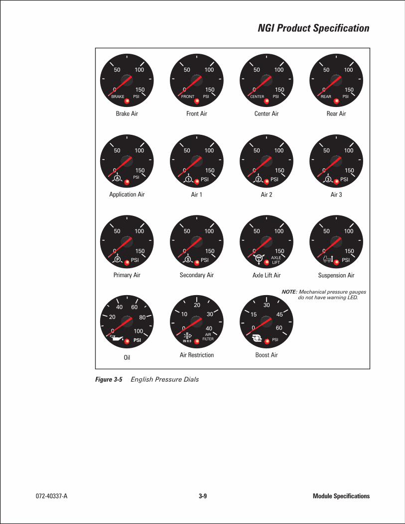
Standard pressure dials are shown in Figure 3-5 on page 3-9 (English) and Figure 3-6on page 3-10 (metric). Response curves must be specified by the customer at timeof order.
The pressure at which the gauge warning LED turns on to indicate low (or high)pressure varies according to the application (for example, oil pressure = 15 psi, airpressure = 65 psi) and is specified by the customer for each pressure gauge.
Mechanical air pressure gauges are also available and do not require any converter.They contain Bourdon tube pointer movements instead of stepper motors, they donot contain warning LEDs, perform no power-on calibration, and cannot be testedusing the mode and set switches. They appear identical to other NGI gauges andconnect to the NGI bus only to obtain backlight power and ground.
Air pressure fittings (screw-on, press-to-connect, etc.) are specified by the customer.
3.2.4 Temperature Gauges
Temperature gauges receive their data from temperature sensors with discrete ana-log connections to the SCU, from the vehicle data bus through the SCU, or from theNGI bus through a data converter such as that described in Section 2.9 on page 2-5.Standard English and metric temperature dials are shown in Figure 3-7 on page 3-11.
NGI Product Specification
072-40337-A 3-5 Module Specifications

Standard SCUs accept temperature sensors having a resistance range from 80 to400K ohms. The desired response must be specified by a resistance curve (see ex-ample in Figure 3-10 on page 3-12).
The temperature at which the gauge warning LED turns on to indicate high or lowtemperature (or both) varies according to the application (water temperature, oiltemperature) and is specified by the customer.
3.2.5 Fuel Level Gauge
Fuel level gauges commonly receive their data using a resistive input from a levelsensor in the fuel tank connected to one of the SCU’s analog inputs. Standard dialsare shown in Figure 3-8 on page 3-11. The desired response must be specified by aresistance curve (see example in Figure 3-11 on page 3-13).
When the fuel level sender signal indicates 1/8 tank or less, the SCU will turn thewarning LED on to indicate low fuel. Hysteresis is employed to eliminate erratic indi-cations due to tank slosh.
3.2.6 Voltmeters and Ammeters
Voltmeters can be configured to obtain their data either from the vehicle data busthrough the SCU, from an analog input to the SCU, or directly from the SCU. The lat-ter method requires no connector input because the SCU uses the power connec-tion at its input plug to sample the battery voltage. The warning LED is controlled bythe SCU and turns on when the voltage drops below 10 volts or rises above 18 volts(below 20 and above 32 volts for 24V systems). Standard dials are shown in Figure3-8 on page 3-11.
3.2.7 Ammeters
Ammeters receive their inputs through a discrete connection to the SCU. Althoughthey contain warning LEDs controlled by the SCU, the warning LEDs remain off un-less otherwise specified. Standard ammeter dials are shown in Figure 3-8 (page 3-11).
3.2.8 Multiple Display Modules
Gauges that display more than one parameter can be specified in 33/8-or 5-inch casediameters to achieve a significant space savings. Such modules must be specifiedby the customer for parameter indicated, pointer sweep degrees and direction,pointer zero point, and desired graphics. Examples of multiple display modules areshown in Figure 3-4 (page 4).
Module Specifications 3-6 072-40337-A

NGI Product Specification
072-40337-A 3-7 Module Specifications
Figure 3-2 Speedometer Dials

Module Specifications 3-8 072-40337-A
Figure 3-3 Tachometer Dials
Figure 3-4 Five-Inch Combination Dials
NGI Product Specification
072-40337-A 3-9 Module Specifications
Figure 3-5 English Pressure Dials

Module Specifications 3-10 072-40337-A
Figure 3-6 Metric Pressure Dials

NGI Product Specification
072-40337-A 3-11 Module Specifications
Figure 3-7 Temperature Dials
Figure 3-8 Other Standard Dials

Module Specifications 3-12 072-40337-A
Figure 3-9 Example Pressure Sensor Output Resistance Curve
Figure 3-10 Example Temperature Sender Curve

NGI Product Specification
072-40337-A 3-13 Module Specifications
Figure 3-11 Example Resistance Curve from a Fuel Level Sensor

3.2.9 Light Bars
The standard light bar contains 16 telltales and is designed to work with a batteryvoltage between +9 and +32 VDC. Maximum current draw is about 400 mA duringbulb test when all 16 telltales are on, minimum current draw is less than 20 mAwhen all telltales are off.
In addition to the examples shown in Figure 3-12, other icons, layouts, and multiplelight bars can be specified.
3.2.10 Telltale Control
Each telltale can be controlled either by direct switched inputs to the light bar, orby the SCU over the NGI bus, or by both methods.
• Direct Inputs to Light Bar -
a. Four Active HI Switched Inputs - Switching these inputs to batteryvoltage turns their corresponding telltales on. These inputs sinkabout 20 mA.
b. Eight Active LO Switched Inputs - Switching these inputs toground (i.e. below +.075 VDC) turns their corresponding telltaleson. These inputs source about 20 mA.
c. Four Configurable Inputs - These can be controlled by either anactive-high input or an active-low input, depending upon which in-put pin is used. The active low inputs source about 20 mA, and theactive high inputs (pins 12, 15, 19, and 20) sink about 20 mA ofpulsed current for contact-cleaning purposes.
Module Specifications 3-14 072-40337-A
Figure 3-12 Examples of Telltale and Light Bar Designs

Note - High and low configurable inputs must not be connected at thesame time to an individual telltale. Doing so and applying activehigh and low signals to them simultaneously may damage the unit.
• SCU-Driven Inputs - The SCU can control telltales over the NGI bus in anyof the following ways:
a. Based on messages it receives from the vehicle data bus. Com-mon examples of this are low oil pressure and high coolant tem-perature.
b. Based on discrete analog or switched inputs to the SCU and inter-nal calculations. For example, the SCU can be programmed at thefactory to light a Low Fuel telltale when the analog signal from afuel level sender reaches some predetermined, customer-speci-fied value, or to turn on a Coolant Level telltale when a coolantlevel switch opens or closes. The SCU can apply hysteresis to theinput to eliminate the effects of fuel or water slosh.
c. Based on an internal timing function. For example, the SCU canturn a seatbelt icon on each time the ignition is switched on andautomatically turn it off 60 seconds later, eliminating the need for aseatbelt continuity switch.
d. Based on a combination of the preceding.
The customer specifies the following for the light bar and each telltale:
• Number and physical characteristics (size, shape) of light bars
• Positions, color, and design of each icon
• Control Method: switch input directly to light bar, from SCU, or combina-tion thereof
• Active state for switched inputs to light bar (low, open, or high)
• If the telltale is controlled by the SCU, the data input to the SCU (vehicledata bus, direct switch or analog input, or internally programmed delay)
• Power-on initialization display pattern (all at once, alternating checker-board pattern, etc.)
3.3 Alphanumeric Display
The AN Display is a backlit, positive-mode liquid crystal display (LCD) located inthe speedometer. The following displays and functions can be selected:
• Odometer (default function in standard systems)
• Two Independent Trip Odometers
• Engine Hourmeter
• Diagnostic Test Mode
NGI Product Specification
072-40337-A 3-15 Module Specifications

Unnecessary functions (for example, the odometer and trip odometers in stationaryapplications) can be disabled at the factory so that they do not appear.
3.3.1 Default Display or Function
The default display or function is that which appears after the power-on initializationsequence is complete and after any unacknowledged messages have been dis-played. It is factory-programmed to the customers’ specification. If unspecified, thedefault function is the odometer. The odometer, trip odometer, and hourmeter dis-plays will revert to the default function 15 seconds after the mode switch was lastpressed.
3.3.1.1 User-Defined Default FunctionThis option causes the last selected function to become the default function.
3.3.1.2 Persistency OptionNormally a function is active, or persists, for 15 seconds after the mode or set switchis last pressed. After 15 seconds it is automatically replaced by the default function.The persistency option causes the last selected function to remain active (alsothrough ignition off/on conditions) until the user presses the mode switch, whichthen returns the display to the default function.
3.3.2 Custom Messages
The wording in these functions and displays cannot be altered. However, the cus-tomer can define up to 30 additional messages and the conditions under which theywill appear. Each user-defined message can contain up to seven characters and isstored in and controlled by the SCU. A Reset message (see Section 3.3.6.4.3 onpage 3-16) is a typical application for custom messages.
3.3.3 Odometer Display and Function
The odometer displays the vehicle odometer without leading zeros and up to999999.9, to the nearest tenth. After that, the decimal point is dropped and thedisplay rolls over to 1000000, continues to 9999999 and then rolls over to
0.0.
Pressing the set switch while the odometer is displayed toggles the units of distancebetween miles and kilometers. The selected units of distance will stay set through ig-nition cycles.
The vehicle odometer value is stored in an EEPROM in the SCU and is notresettable. The value is calculated, stored, and displayed using one of the follow-ing methods:
• Direct from Databus - The SCU displays the total vehicle distance (TVD)value broadcast by the Engine ECU on the vehicle data bus.
• Speed Integration Method - When the ignition is switched on, the SCUretrieves the current odometer value stored in the SCU EEPROM. TheSCU then calculates a new current odometer value according to the
Module Specifications 3-16 072-40337-A

formula D=RT and updates the display every half second. Every 20 milesand every time the ignition is switched off, the SCU stores the currentodometer value in the EEPROM.
• Match Method - When the ignition is switched on, the SCU retrieves thecurrent odometer value from the EEPROM and compares it with the TVDon the vehicle data bus. If the two are within 0.2 miles of each other, theSCU displays the current odometer value and increments it every tenthmile thereafter using distance tick marks from the vehicle data bus. Everytenth mile and every time the ignition is switched off, the SCU stores thecurrent odometer value in the EEPROM.
Various options exist to deal with cases where the values do not match.These should be discussed with AMETEK and it is up to the customer tospecify the desired method.
The SCU will display a series of dashes (-------) whenever the odometerfunction is selected if:
• The SCU fails to store the its odometer reading
• Odometer data is not available from the vehicle
• The engine stops broadcasting TVD
The customer specifies which method to use for calculating the odometer value.
3.3.4 Independent Trip Odometer Display and Function
The NGI System provides two independently resettable and uniquely identified tripodometers (i.e., TRIP 1 and TRIP 2). Each can display up to 9999.9miles or kilo-meters and the SCU stores these values in EEPROM. The SCU calculates trip dis-tance for each trip odometer using one of the previously described methods and thevalue of the trip odometer when it was last reset.
The user resets a trip odometer to zero by pressing the set switch while that tripodometer is displayed.
3.3.5 Hourmeter Display and Function
The hourmeter displays total engine hours. Each time the ignition is switched on andevery 10 seconds thereafter, the SCU requests total engine hours data (MID 128, PID194) from the Engine ECU. The SCU does not store total engine hours, and its valueis not resettable. If total engine hours data is not available from the vehicle, the SCUwill display a series of dashes (-------) whenever the hourmeter function isselected.
Total engine hours is displayed to the nearest tenth, without leading zeros and up to9999.9. After that, the display rolls to 0.0.
NGI Product Specification
072-40337-A 3-17 Module Specifications

3.3.6 Other Functions
In addition to the odometer and hourmeter displays and functions, the AN Dis-play has other functions:
• User-Initiated Diagnostics
• Fault and NGI Warning Messages
3.3.6.1 User-Initiated Diagnostic FunctionThe Diagnostic function allows one to test all display modules (except mechanicalpressure gauges) either automatically or manually. Functionality of the diagnostics isshown in Figure 3-15 on page 3-25.
The customer can specify up to five enabling conditions which must be met beforethe Diagnostic function is enabled. Some examples are: transmission in neutral, parkbrake applied, engine speed less than 1000 rpm, etc.
3.3.6.1.1 Auto Test
Pressing the set switch while AUTO is displayed starts the four-phase Auto Testsequence shown in Figure 3-15 on page 3-25. During each phase, the SCU generatesthe data for the Alphanumeric Display, gauge pointers, warning LEDs, and telltalecontrol and sends it to the modules over the NGI bus:
• Phase One - MIN is displayed, all pointers move in unison to mini-mum scale, all warning LEDs and telltales are off.
• Phase Two - MID is displayed, all pointers move in unison to mid-scale, all warning LEDs remain off, and the odd-numbered telltales turnon.
• Phase Three - MAX is displayed, all pointers move in unison tomaximum scale, all warning LEDs remain off, the odd-numbered telltalesturn off, and the even-numbered telltales turn on.
• Phase Four - LED is displayed, all pointers move in unison back tominimum scale, all warning LEDs turn on, and all telltales turn on. At theend of this phase, AUTO is displayed.
Pressing the mode or set switch while the Auto Test sequence is active halts the se-quence and returns the display to AUTO . If the instrumentation passes the AutoTest sequence, all gauges, warning LEDs, and telltales are functioning correctly.
Note - Do not confuse the Auto Test function with the power-up initializa-tion sequence.
Module Specifications 3-18 072-40337-A

3.3.6.2 Manual Test
Pressing the mode switch while AUTO is displayed activates (but does notstart) the Manual Test function shown in Figure 3-16 on page 3-26 and displaysMANUAL . The Manual Test function is the same as the Auto Test sequence ex-cept that the user can select which modules to test and must press the setswitch to move from one phase to the next as follows:
• Use the set switch while MANUAL is displayed to select the module tobe tested, starting with SCU .
• When the desired module’s name is displayed, press the set switch tostart testing that module or press the mode switch to select a differentmodule.
Press the set switch to step through the test, or press the mode switch to stop the test.
3.3.6.3 Fault MessagesWhen a device (or ECU) attached to the vehicle data bus detects a fault, it can placean active fault message on the vehicle data bus. The message contains the device IDcode of the device that detected the fault along with a specific failure code (for ex-ample, Engine ECU—low oil pressure). Each time the SCU receives an active faultmessage, it automatically displays the device ID code for 12 seconds and then storesit for later recall and viewing. It does not display the specific failure code.
If the set switch is pressed while FAULTS is displayed, the SCU will broadcast afault request message on the vehicle data bus and will display POLLING (see Fig-ure 3-15 on page 3-25). Devices connected to the bus will respond by placing theiractive fault messages on the bus.
After receiving all the active fault messages, the SCU displays their device IDs one-at-a-time in 3-second intervals. Up to 128 device IDs can be displayed. Pressing themode or set switch during this time exits the Fault mode.
3.3.6.4 NGI Warning MessagesAn NGI Warning Message is one that the SCU displays under certain SCU input con-ditions. The customer specifies the displayed text and defines the input conditionsunder which it is displayed. The text can be up to seven characters long, and theconditions can be vehicle data bus messages, discrete inputs to the SCU, or a com-bination of both. NGI Warning Messages can be accompanied by a gauge warningLED, a telltale indication, an audible alert, or any combination as specified by thecustomer. Examples of NGI Warning Messages are shown in Table 3-1.
NGI Product Specification
072-40337-A 3-19 Module Specifications

3.3.6.4.1 NGI Warning Message PrioritiesThe SCU assigns a priority from 1 through 28 for everything it displays. The prioritydetermines the order in which something is displayed. The higher the number, thehigher the priority. When a condition occurs that results in an NGI Warning Message,the SCU assigns it a priority as well. Items are displayed according to the priority lev-els shown in Table 3-2.
Loss-of-data messages (NO SPDO, NO HRS , NO ODO , NO DATA ) do nothave a configurable priority and will override the NGI Warning Messages if present.
3.3.6.4.2 Unacknowledgable MessagesAn unacknowledgable message is one that the driver cannot unacknowledge. Exam-ples are shown in Table 3-1. When an unacknowledgable message appears, thedriver can press the Mode switch and scroll through the message list, but he cannotlower the unacknowledgable message’s priority by using the Set button. Thirty sec-onds after the last button press, the unacknowledgable message will reappear.
The customer specifies which messages are unacknowledgable.
Module Specifications 3-20 072-40337-A
NGIWARNINGMESSAGE
INPUT CONDITION ACKNOWLEDGEABLE
AIR1 LO Switched input to SCU No
AIR2 LO Switched input to SCU No
OIL LO Vehicle data bus message No
H20T HI Analog input to SCU Yes
OILT HI Analog input to SCU Yes
TRAN HI Vehicle data bus message Yes
NO SPDO SCU detects no speed data forfive consecutive seconds
No
NO HRS SCU detects no engine hourdata for 15 consecutive seconds
No
NO ODO SCU detects no odometer datafor 15 consecutive seconds
No
NO DATA SCU detects no speed, enginehours and odometer data for 15consecutive seconds
No
Table 3-1 Examples of NGI Warning Messages

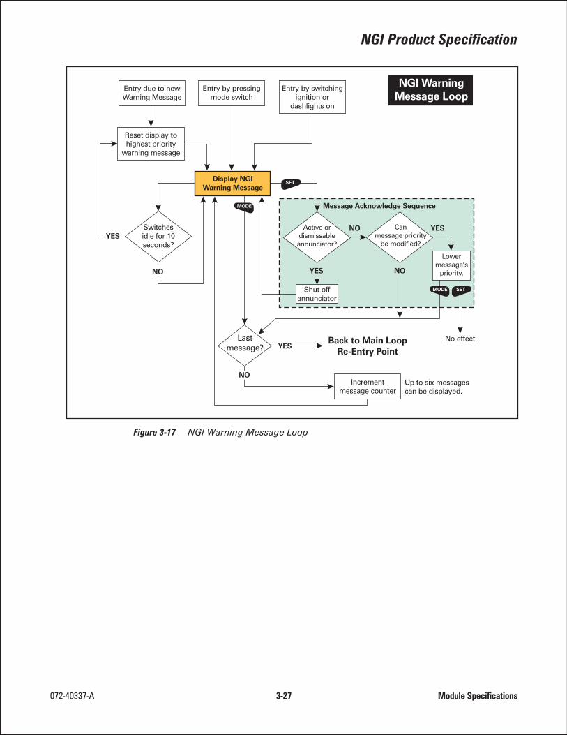
3.3.6.4.3 Acknowledging an NGI Warning MessageWhen an NGI Warning Message first appears, it is considered unacknowledged.At this point, the operator has four options (see Figure 3-17). He can:
• Silence the buzzer by pressing the set switch once while the message isdisplayed.
• Acknowledge the message by pressing the set switch a second timewhile the message is displayed. The SCU will then lower the message’spriority to six, and lower the priorities of all previously acknowledgedmessages by one. If another NGI Warning Message (unacknowledged oracknowledged) exists, it will be displayed; otherwise, the SCU will displaythe odometer as shown in Figure 3-17.
• Display the next NGI Warning Message by pressing the mode switch. Ifthere are no more messages to display, the SCU re-enters the Main Loopand displays the odometer.
• Do nothing - If neither the mode nor the set switch has been pressed for15 seconds, the SCU will display the message with the highest priority. Analternative to this is to have the SCU continuously display the unacknowl-edged message (see Figure 3-18 on page 3-28). This option must be spec-ified by the customer.
Up to six NGI Warning Messages can be queued. If more than six messages are ac-knowledged, the oldest one is removed from the queue. Queued messages are re-tained as long as the SCU receives battery power.
NGI Product Specification
072-40337-A 3-21 Module Specifications
MESSAGE DESCRIPTION TYPICAL PRIORITYLEVEL
Loss-of-Data Messages These override allother messages
NGI Warning Messages 28 - 17
Reserved 16, 15, 14
Odometer 13
Trip 1 12
Trip 2 11
Engine Hours 10
Reserved 9, 8
Diagnostics 7
Acknowledged WarningMessages
6 - 1
Table 3-2 Message Priorities

3.3.7 Alphanumeric Display Backlighting
When the dashlights are off, the LCD backlighting is set to a fixed level for best visi-bility. When the dashlights are on, the backlighting is controlled by the vehicle’sdashlight dimming control.
3.4 Audible Warning Device (Buzzer)
The buzzer is a software-driven, miniature piezo-electric device. Its pitch is 2 kilo-Hertz and its emitted sound level is 85 dB minimum measured 10 cm from the rearof the speedometer housing. The buzzer can be controlled by any device on the ve-hicle data bus, although in standard systems it is controlled by the SCU in responseto external events.
3.4.1 Customer-Specified Information for Alphanumeric Display and Buzzer
The customer specifies the following information:
• NGI Warning Messages (up to 30) - Text string (up to 7 characters); con-ditions under which it is displayed; priority; acknowledgeability
• Other Indications - Whether an associated gauge warning LED or telltaleis on; whether the buzzer sounds when the text string is displayed
• Diagnostic Function - Up to five enabling conditions that must be met be-fore this function can be activated
• User-Defined Default Option - See Section 3.3.1.1 on page 3-16
• Persistency Option - See Section 3.3.1.2 on page 3-16
• Buzzer Events, such as whether the buzzer sounds during the power-oninitialization sequence
• System response to an NGI Warning Message that has been ignored
3.5 System Operation
Applying battery voltage to the system’s ignition input fully activates the system asshown in Figure 3-14 on page 3-24.
The system can be partially activated when the ignition is off by pressing the modeor set switches. This allows one to use the display without an ignition key. The dis-play turns off 10 seconds after the last press of the mode or set switch. Turning thebacklighting on activates the display as long as the backlighting remains on.
3.5.1 Power-On Initialization Sequence
Each time ignition power is applied, the system performs the initialization sequenceshown in Figure 3-13 (page 3-23). All gauge pointers are automatically re-zeroed andall telltales and gauge warning LEDs momentarily turn on, allowing the user to checktheir functionality.
Module Specifications 3-22 072-40337-A

Note - If the battery voltage drops low enough when the starter is engaged,the system may repeat the sequence when the input power comesback up to normal.
NGI Product Specification
072-40337-A 3-23 Module Specifications
Figure 3-13 Power-On Initialization Sequence

Module Specifications 3-24 072-40337-A
Figure 3-14 Main Loop

NGI Product Specification
072-40337-A 3-25 Module Specifications
Figure 3-15 Diagnostic Test Loop

Module Specifications 3-26 072-40337-A
Figure 3-16 Manual Test Loop
NGI Product Specification
072-40337-A 3-27 Module Specifications
Figure 3-17 NGI Warning Message Loop

Module Specifications 3-28 072-40337-A
Figure 3-18 NGI Warning Sticky Message Loop

4 Electrical Specifications
4.1 General Panel Wiring
Figure 4-1 illustrates the rear of a panel containing a speedometer with a built-inSCU, tachometer, four 2-inch gauges, Light Bar, and one of many possible connec-tion schemes.
Connections to the vehicle wiring harness are shown in red. This wiring and its asso-ciated connectors are usually supplied by the OEM but can also be ordered from andmanufactured by AMETEK Dixson. The NGI Cable assemblies (shown in blue) arepart of the NGI System and are supplied by AMETEK Dixson.
072-40337-A 4-1 Electrical Specifications
Figure 4-1 Panel Wiring

4.2 Speedometer/SCU Connections
Notes -
• Analog inputs are from temperature sensors, fuel level sensors and othersensors whose outputs vary continuously as a function of the monitoredparameter. Valid inputs range from zero to 6,400 ohms, or from 0 to +32VDC. Reduced ranges, offset ranges, and input linearization can be config-ured by the factory to meet most any need. Please consult AMETEKDixson for application assistance.
• Active HI inputs are switched between battery voltage (i.e., between +9and +32 VDC) and open circuit.
• Active LO inputs are switched between ground and open circuit. Pull-upsare not required. Programmable inputs are configured at the factory asadditional active high or active low inputs
• External mode and set switch inputs are active when connected toground, and inactive when left open. Pull-ups are not required. They re-place the mode and set switches when the standard ones are not avail-able or not desired.
Electrical Specifications 4-2 072-40337-A
Figure 4-2 SCU Connections

4.3 Light Bar Connections
NGI Product Specification
072-40337-A 4-3 Electrical Specifications
Figure 4-3 Light Bar Connections
ELECTRICAL PARAMETER SPECIFICATION
Operating voltage 9 to 32 volts DC
Input Voltage Protection (Cold Cranking,Reverse Polarity, Series Charging)
Meets the requirements of SAE J1455Section 4.11.1
Load Dump, Inductive Switching, MutualCoupling
Meets the requirements of SAE J1455Sections 4.11.2.2.1, 4.11.2.2.2, and4.11.2.2.3
Electromagnetic Conductance(Susceptibility)
Meets the requirements of SAEJ1113/21 and SAE J1812
Electromagnetic Conductance(Radiated Emissions)
Meets the requirements of SAEJ1113/41 Sections 8, 9
Other electrical transients: conductednoise
Meets the requirements of SAE J1455and SAE J1113
Electrostatic Discharge (non-operatingand operating)
Meets the requirements of SAE J1455Sections 4.11.2.2.5.1 and 4.11.2.2.5.2
Table 4-1 Electrical Specifications


5 Mounting Specifications
072-40337-A 5-1 Mounting Specifications
Figure 5-1 Module Dimensions

Mounting Specifications 5-2 072-40337-A
Figure 5-2 Gauge and Light Bar Mounting into Typical Panel

6 Environmental and Reliability Specifications
6.1 Environmental Specifications
6.2 Reliability Specifications
6.2.1 Reliability
072-40337-A 6-1 Environmental and Reliability Specifications
ENVIRONMENTAL PARAMETER SPECIFICATION
Operating and Non-Operating Temperature –40 to +85C
Thermal Cycling Meets requirements of SAE J1455, Section4.1.3.2
Thermal Shock Meets requirements of SAE J1455, Section4.1.3.2
Humidity Meets requirements of SAE J1455, Section 4.2
Mechanical Shock (handling and shipping) Meets requirements of SAE J1455, Sections4.10.3.1 and 4.10.2.2
Operating Shock Meets requirements of MIL-STD-2-2F, Method213B, Test Condition J
Operating Vibration 0.06354 G2/Hz, 5 Hz to 2 KHz random
Mechanical Vibration Meets requirements of SAE J1399, notes 3and 4
Chemical Splash (soap, wax, coffee, soda) Meets requirements of SAE J1455, Sections4.4.1
Table 6-1 Environmental Specifications
PARAMETER SPECIFICATION
Gauge Accuracy ±2 percent of range
System Accuracy ±2 percent of range
Fuel Gauge System Accuracy Empty: –9% to 0% of rangeFull: 0 to +9% of range
Table 6-2 Reliability Specifications
6.3 Serviceability
The instrumentation maximizes serviceability. No specialized tools are required to in-stall or remove the components from the vehicle. None of the individual modulesare serviceable at the field or dealer level. If a component is deemed defective, it issimply replaced.
To help verify the operational status of individual components, the instrumentationincludes diagnostics that can be used at the user or dealer level. These are describedelsewhere in this specification.
END OF DOCUMENT
Environmental and Reliability Specifications 6-2 072-40337-A