product safety, installation, and user … safety, installation, and user guide ... experts in...
TRANSCRIPT
MN000350A01.book Page 1 Tuesday, March 29, 2016 2:14 PM
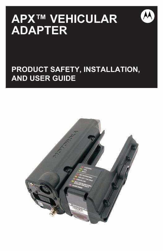
APX™ VEHICULARADAPTER
PRODUCT SAFETY, INSTALLATION,AND USER GUIDE

MN000350A01.book Page 2 Tuesday, March 29, 2016 2:14 PM
MN000350A01.book Page 1 Tuesday, March 29, 2016 2:14 PM
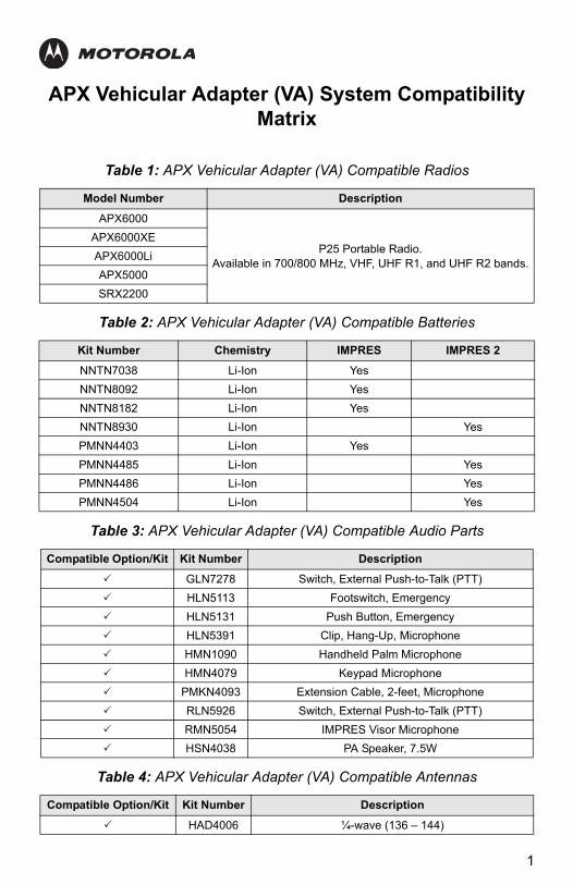
APX Vehicular Adapter (VA) System Compatibility Matrix
Table 1: APX Vehicular Adapter (VA) Compatible Radios
Model Number Description
APX6000
P25 Portable Radio.Available in 700/800 MHz, VHF, UHF R1, and UHF R2 bands.
APX6000XE
APX6000Li
APX5000
SRX2200
Table 2: APX Vehicular Adapter (VA) Compatible Batteries
Kit Number Chemistry IMPRES IMPRES 2
NNTN7038 Li-Ion Yes
NNTN8092 Li-Ion Yes
NNTN8182 Li-Ion Yes
NNTN8930 Li-Ion Yes
PMNN4403 Li-Ion Yes
PMNN4485 Li-Ion Yes
PMNN4486 Li-Ion Yes
PMNN4504 Li-Ion Yes
Table 3: APX Vehicular Adapter (VA) Compatible Audio Parts
Compatible Option/Kit Kit Number Description
GLN7278 Switch, External Push-to-Talk (PTT)
HLN5113 Footswitch, Emergency
HLN5131 Push Button, Emergency
HLN5391 Clip, Hang-Up, Microphone
HMN1090 Handheld Palm Microphone
HMN4079 Keypad Microphone
PMKN4093 Extension Cable, 2-feet, Microphone
RLN5926 Switch, External Push-to-Talk (PTT)
RMN5054 IMPRES Visor Microphone
HSN4038 PA Speaker, 7.5W
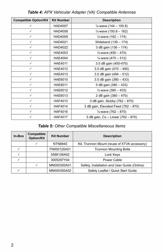
Table 4: APX Vehicular Adapter (VA) Compatible Antennas
Compatible Option/Kit Kit Number Description
HAD4006 ¼-wave (136 – 144)
1
MN000350A01.book Page 2 Tuesday, March 29, 2016 2:14 PM
HAD4007 ¼-wave (144 – 150.8)
HAD4008 ¼-wave (150.8 – 162)
HAD4009 ¼-wave (162 – 174)
HAD4021 Wideband (136 – 174)
HAD4022 3 dB gain (136 – 174)
HAE4003 ¼-wave (450 – 470)
HAE4004 ¼-wave (470 – 512)
HAE4011 3.5 dB gain (450-470)
HAE4012 3.5 dB gain (470 – 495)
HAE4013 3.5 dB gain (494 – 512)
HAE6010 3.5 dB gain (380 – 433)
HAE6011 5 dB gain (380 – 433)
HAE6012 ¼-wave (380 – 433)
HAE6013 2 dB gain (380 – 470)
HAF4013 3 dB gain, Stubby (762 – 870)
HAF4014 3 dB gain, Elevated Feed (762 – 870)
HAF4016 ¼-wave (762 – 870)
HAF4017 3 dB gain, Co – Linear (762 – 870)
Table 5: Other Compatible Miscellaneous Items
In-BoxCompatible Option/Kit
Kit Number Description
NTN8940 Kit, Trunnion Mount (reuse of XTVA accessory)
FN000125A01 Trunnion Mounting Bolts
5586126A02 Lock Keys
3005297Y04 Power Cable
MN000350A01 Safety, Installation and User Guide (Online)
MN000350A02 Safety Leaflet / Quick Start Guide
Table 4: APX Vehicular Adapter (VA) Compatible Antennas
Compatible Option/Kit Kit Number Description
2
MN000350A01.book Page 3 Tuesday, March 29, 2016 2:14 PM
ASTRO™ APX™ Vehicular Adapter (APX VA) RF Energy Exposure and Product Safety
The information provided in this document supersedes the general safety information contained in user guides published prior to January 2008.
RF Energy Exposure Awareness and Control Information, and Operational Instructions for Federal Communication Commission (FCC) Occupational Use Requirements
Note: This radio is intended for use in occupational or controlled conditions, where users have full knowledge of their exposure and can exercise control over their exposure to meet Federal Communication Commission (FCC) limits. This radio device is NOT authorized for general population, consumer, or any other user.
This two-way radio uses electromagnetic energy in the RF spectrum to provide communications between two or more users over a distance. It uses RF energy or radio waves to send and receive calls. RF energy is one form of electromagnetic energy. Other forms include, but not limited to, sunlight and X-rays. RF energy, however, should not be confused with these other forms of electromagnetic energy, which when used improperly, can cause biological damage. Very high level of X-rays, for example, can damage tissues and genetic material.
Experts in science, engineering, medicine, health, and industry work with organizations to develop standards for safe exposure to RF energy. These standards provide recommended levels of RF exposure for both workers and the general public. These recommended RF exposure levels include substantial margins of protection.
Before using this radio, read the information in this section which contains important operating instructions for safe usage and radio RF energy awareness and control information for compliance with RF energy exposure limits in applicable national and international standards.
3
MN000350A01.book Page 4 Tuesday, March 29, 2016 2:14 PM
All Motorola two-way radios are designed, manufactured, and tested to ensure that they meet government-established RF exposure levels. In addition, manufacturers also recommend specific operating instructions to users of two-way radios. These instructions are important because they inform users about RF energy exposure and provide simple procedures on how to control it.
Please refer to the following web sites for more information on what RF energy exposure is and how to control your exposure to ensure compliance with established RF exposure limits.
http://www.fcc.gov/oet/rfsafety/rf-faqs.html http://www.osha.gov/SLTC/radiofrequencyradiation/index.html
Federal Communication Commission (FCC) Regulations
The FCC rules require manufacturers to comply with the FCC RF energy exposure limits for mobile two-way radios before they can be marked in the U.S. When two-way radios are used as a consequence of employment, the FCC requires users to be fully aware of and able to control their exposure to meet occupational requirements. Exposure awareness can be facilitated by the use of a label directing users to specific user awareness information. Your Motorola two-way radio has a RF exposure product label. Also, your Motorola user manual, and this RF Energy Exposure and Product Safety section, includes information and operating instructions required to control your RF exposure and to satisfy compliance requirements.
Compliance with RF Exposure Standard
Your Motorola two-way radio is designed and tested to comply with a number of national and international standards and guidelines (listed below) regarding human exposure to RF electromagnetic energy. This radio complies with the Institute of Electrical and Electronics Engineers (IEEE) and International Commission on Non-Ionizing Radiation Protection (ICNIRP) exposure limits for occupational or controlled RF exposure environment at duty factors of up to 50% talk-50% listen and is authorized by the FCC for occupational use only. In terms of measuring RF energy for compliance with the FCC exposure guidelines, your radio antenna radiates measurable RF energy only while it is transmitting (during talking), not when it is receiving (listening) or in standby mode.
Your Motorola two-way radio complies with the following RF energy exposure standards and guidelines:
4
MN000350A01.book Page 5 Tuesday, March 29, 2016 2:14 PM
• United States Federal Communications Commission (FCC), Code of Federal Regulations; 47 CFR et seq.
• FCC, OET Bulletin 65.
• Institute of Electrical and Electronic Engineers (IEEE) C95.1.
• International Commission on Non-Ionizing Radiation Protection (ICNIRP).
• Ministry of Health (Canada) Safety Code 6.
• Industry Canada RSS-102, Australian Communications Authority Radiocommunications Standard et seq.
• ANATEL ANNEX to Resolution No. 303 et seq.
RF Exposure Compliance and Control Guidelines and Operating Instructions
To control exposure to yourself and others and to ensure compliance with the RF exposure limits, always adhere to the following procedures.
Guidelines
• User awareness instructions should accompany device when transferred to other users.
• Do not use this device if the operational requirements described herein are not met.
Instructions
• Transmit no more than the rated duty factor of 50% of the time. To transmit (talk), push the Push-to-Talk (PTT) button or, for radios equipped with Voice Activation (VOX), speak into the microphone. The red LED will illuminate when the radio is transmitting. To receive calls, release the PTT button, or, for radios equipped with VOX, stop talking. The red LED will extinguish when the radio stops transmitting. Transmitting 50% of the time, or less, is important because this radio generates measurable RF energy exposure only when transmitting (in terms of measuring for standards compliance).
• Transmit only when people outside the vehicle are at least the recommended minimum lateral distance away, shown in Table 1, from the body of a vehicle with a properly installed antenna. This separation distance will ensure that there is sufficient distance from a properly installed (according to installation instructions) externally-mounted antenna to satisfy the RF exposure requirements in the standards listed above.
5
MN000350A01.book Page 6 Tuesday, March 29, 2016 2:14 PM
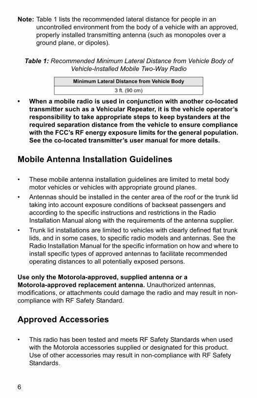
Note: Table 1 lists the recommended lateral distance for people in an uncontrolled environment from the body of a vehicle with an approved, properly installed transmitting antenna (such as monopoles over a ground plane, or dipoles).
• When a mobile radio is used in conjunction with another co-located transmitter such as a Vehicular Repeater, it is the vehicle operator’s responsibility to take appropriate steps to keep bystanders at the required separation distance from the vehicle to ensure compliance with the FCC’s RF energy exposure limits for the general population. See the co-located transmitter’s user manual for more details.
Mobile Antenna Installation Guidelines
• These mobile antenna installation guidelines are limited to metal body motor vehicles or vehicles with appropriate ground planes.
• Antennas should be installed in the center area of the roof or the trunk lid taking into account exposure conditions of backseat passengers and according to the specific instructions and restrictions in the Radio Installation Manual along with the requirements of the antenna supplier.
• Trunk lid installations are limited to vehicles with clearly defined flat trunk lids, and in some cases, to specific radio models and antennas. See the Radio Installation Manual for the specific information on how and where to install specific types of approved antennas to facilitate recommended operating distances to all potentially exposed persons.
Use only the Motorola-approved, supplied antenna or a Motorola-approved replacement antenna. Unauthorized antennas, modifications, or attachments could damage the radio and may result in non-compliance with RF Safety Standard.
Approved Accessories
• This radio has been tested and meets RF Safety Standards when used with the Motorola accessories supplied or designated for this product. Use of other accessories may result in non-compliance with RF Safety Standards.
Table 1: Recommended Minimum Lateral Distance from Vehicle Body of Vehicle-Installed Mobile Two-Way Radio
Minimum Lateral Distance from Vehicle Body
3 ft. (90 cm)
6

MN000350A01.book Page 7 Tuesday, March 29, 2016 2:14 PM
• For a list of Motorola-approved antennas and other accessories, visit the following web site which lists the approved accessories for the APX VA or refer to “APX Vehicular Adapter (VA) System Compatibility Matrix” on page 1.
http://www.motorolasolutions.com
Additional Information
For additional information on exposure requirements or other training information, visit
http://responsibility.motorolasolutions.com/index.php/downloads/dow07-rfexposureassessmentstand/
Compliance and Control Guidelines and Operating Instructions for Mobile Two-Way Radios Installed as Fixed Site Control Stations
If mobile radio equipment is installed at a fixed location and operated as a control station or as a fixed unit, the antenna installation must comply with the following requirements in order to ensure optimal performance and compliance with the RF energy exposure limits in the standards and guidelines listed on page 3.
• The antenna should be mounted outside the building on the roof or a tower if at all possible.
• As with all fixed site antenna installations, it is the responsibility of the licensee to manage the site in accordance with applicable regulatory requirements and may require additional compliance actions such as site survey measurements, signage, and site access restrictions in order to ensure that exposure limits are not exceeded.
• For additional installation information, see the guidelines for minimum separation distances provided above in the RF Exposure Compliance and Control Guidelines and Operating Instructions section of this document.
7
MN000350A01.book Page 8 Tuesday, March 29, 2016 2:14 PM
Compliance and Control Guidelines and Operating Instructions for Mobile Two-Way Radios Installed on Maritime Vessels
If mobile radio equipment is installed on a vessel and operated as a fixed unit, the antenna installation must comply with the following requirements in order to ensure optimal performance and compliance with RF energy exposure limits in the standards and guidelines listed on page 3.
• An antenna intended for Maritime operation should be chosen and installed according to the manufacturer’s recommendations.
• The antennas should be mounted solidly to the vessel structure at the highest location possible.
• As with all radio antenna installations, it is the responsibility of the operator to maintain adequate distances from the antenna and all personnel on board the vessel or adjacent to the vessel.
• For additional installation information, see the guidelines for minimum separation distances proved above in the RF Exposure Compliance and Control Guidelines and Operating Instructions section of this document.
Electromagnetic Interference or Compatibility
Note: Nearly every electronic device is susceptible to electromagnetic interference (EMI) if inadequately shielded, designed, or otherwise configured for electromagnetic compatibility. It may be necessary to conduct compatibility testing to determine if any electronic equipment used in or around vehicles or near fixed site antenna is sensitive to external RF energy or if any procedures need to be followed to eliminate or mitigate the potential for interaction between the radio transmitter and the equipment or device.
Facilities
To avoid electromagnetic interference and/or compatibility conflicts, turn off your radio in any facility where posted notices instruct you to do so. Hospitals or health care facilities may be using equipment that is sensitive to external RF energy.
8
MN000350A01.book Page 9 Tuesday, March 29, 2016 2:14 PM
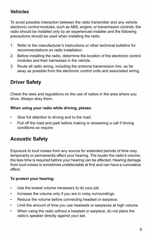
Vehicles
To avoid possible interaction between the radio transmitter and any vehicle electronic control modules, such as ABS, engine, or transmission controls, the radio should be installed only by an experienced installer and the following precautions should be used when installing the radio.
1. Refer to the manufacturer’s instructions or other technical bulletins for recommendations on radio installation.
2. Before installing the radio, determine the location of the electronic control modules and their harnesses in the vehicle.
3. Route all radio wiring, including the antenna transmission line, as far away as possible from the electronic control units and associated wiring.
Driver Safety
Check the laws and regulations on the use of radios in the area where you drive. Always obey them.
When using your radio while driving, please:
• Give full attention to driving and to the road.
• Pull off the road and park before making or answering a call if driving conditions so require.
Acoustic Safety
Exposure to loud noises from any source for extended periods of time may temporarily or permanently affect your hearing. The louder the radio’s volume, the less time is required before your hearing can be affected. Hearing damage from loud noises is sometimes undetectable at first and can have a cumulative effect.
To protect your hearing:
• Use the lowest volume necessary to do your job.
• Increase the volume only if you are in noisy surroundings.
• Reduce the volume before connecting headset or earpiece.
• Limit the amount of time you use headsets or earpieces at high volume.
• When using the radio without a headset or earpiece, do not place the radio’s speaker directly against your ear.
9
MN000350A01.book Page 10 Tuesday, March 29, 2016 2:14 PM
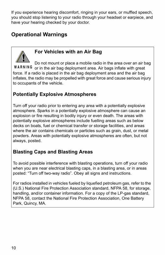
If you experience hearing discomfort, ringing in your ears, or muffled speech, you should stop listening to your radio through your headset or earpiece, and have your hearing checked by your doctor.
Operational Warnings
!W A R N I N G
!For Vehicles with an Air Bag
Do not mount or place a mobile radio in the area over an air bag or in the air bag deployment area. Air bags inflate with great
force. If a radio is placed in the air bag deployment area and the air bag inflates, the radio may be propelled with great force and cause serious injury to occupants of the vehicle.
Potentially Explosive Atmospheres
Turn off your radio prior to entering any area with a potentially explosive atmosphere. Sparks in a potentially explosive atmosphere can cause an explosion or fire resulting in bodily injury or even death. The areas with potentially explosive atmospheres include fuelling areas such as below decks on boats, fuel or chemical transfer or storage facilities, and areas where the air contains chemicals or particles such as grain, dust, or metal powders. Areas with potentially explosive atmospheres are often, but not always, posted.
Blasting Caps and Blasting Areas
To avoid possible interference with blasting operations, turn off your radio when you are near electrical blasting caps, in a blasting area, or in areas posted: “Turn off two-way radio”. Obey all signs and instructions.
For radios installed in vehicles fueled by liquefied petroleum gas, refer to the (U.S.) National Fire Protection Association standard, NFPA 58, for storage, handling, and/or container information. For a copy of the LP-gas standard, NFPA 58, contact the National Fire Protection Association, One Battery Park, Quincy, MA.
10
MN000350A01.book Page 11 Tuesday, March 29, 2016 2:14 PM
ASTRO™ APX™ Vehicular Adapter (APX VA) Installation Manual
Installation Instructions
Introduction
This publication describes the complete installation procedure for the ASTRO
APX6000 Vehicular Adapter (APX VA) used with APX6000 series radios. Installation includes planning, mounting, and verification. The APX VA allows an APX6000 portable radio (which includes APX6000, APX6000XE, APX6000Li, APX5000, and SRX2200 models) to operate similar to a mobile radio while the radio is in the adapter. Read these instructions before installing your APX VA.
Installation Requirements for Compliance with RF Energy Exposure Safety Standards
ATTENTION!
This radio system is intended for use in occupational controlled conditions, where users have full knowledge of their exposure and can exercise control over their exposure to meet FCC limits. This radio device is NOT authorized for general population, consumer, or any other use.
To ensure compliance to RF Energy Safety Standards:
• Install only Motorola-approved antenna and accessories.
• Ensure that antenna installation is per “Antenna Installation” section of this manual.
• Ensure that RF Energy Exposure and Product Safety section of this manual is available to the end user upon completion of the installation of this APX VA system.
Before using this product, read the RF Energy Exposure and Safety Section of this manual enclosed with your radio which contains important operating instructions for safe usage and RF energy awareness and control for compliance with applicable standards and regulations.
11

MN000350A01.book Page 12 Tuesday, March 29, 2016 2:14 PM
For a list of Motorola-approved antennas and other accessories, visit the following web site which lists the approved accessories for the APX VA or refer to “APX Vehicular Adapter (VA) System Compatibility Matrix” on page 1.
http://www.motorolasolutions.com
Installation Planning
The Motorola ASTRO™ APX™ Vehicular Adapter (APX VA) is an accessory designed to adapt APX6000 series portable radios for vehicular operation and battery charging. The APX VA System consists of the following components:
• console
• hand-held microphone
• power cable
• trunnion or U-bracket (with its mounting hardware)
• mounting hardware (trunnion to console screws)
• external speaker (optional)
• roof-top antenna (not supplied)
• other optional accessories (installation not covered in this manual)
Before starting the installation, plan the location of the console, microphone, antenna and external speaker (optional). Identify the routing path for all cables. Verify that the cable lengths are sufficient.
Also, check the mounting penetrations required. On most vehicles, it is necessary to penetrate the firewall to reach the battery. Check the opposite side of the firewall for cable clearance before drilling holes, and protect the cable where it passes through the firewall by using grommets (not provided) or other similar protective measures. Survey the firewall for existing holes occupied by vehicle wire harnesses. Often there is an opportunity to route other cables using the same path. Because of the wide variations in vehicle design, these instructions may be modified to suit each particular installation.
Note: This manual assumes that the Console is mounted under the dash. Other mounting configurations are possible but not addressed in this manual.
A properly installed APX VA will minimize service calls and equipment downtime. Motorola recommends adherence to all of the guidelines and instruction when planning the installation:
12

MN000350A01.book Page 13 Tuesday, March 29, 2016 2:14 PM
• Do insert S-hooks (not provided) on cables into restraining holes for strain relief.
• Do use heat-shrink tubing (not provided) on all splices.
• Do ensure that unit cables are not placed under stress, are not exposed to weather, and are not subjected to damage due to engine heat.
• Do retain in-line cable fuses when trimming cables to fit. Locate in-line fuses as close as practical to the supply voltage connection.
• Do not attach the unit to any part of the vehicle that is not rigid or is subject to excessive vibration.
• Do not install unit in areas where rain or snow can easily get into them, such as next to a vehicle window which may be left open.
• Do not dress cables over sharp edges that could cause wear or tearing of cable insulation.
• Do not install the units in locations where they might interfere with the vehicle’s operator or operating controls.
• Do not install the unit where it will be difficult for the operator to reach.
• Do not install the unit where it will interfere with vehicle safety air bag deployment.
Console Location
The optional trunnion (“U”) bracket can be used to mount the APX VA console either off the vehicle floor or under the vehicle dash. The console should first be attached to the bracket, and then the console-bracket combination can be evaluated for the proper mounting location. The console should be mounted to provide:
• 12 inches (30.48cm) of clearance in front of the console for inserting and removing the radio.
• clearance on either side of the console is necessary for inserting and tightening screws to secure the console to the bracket.
• a 6-inch (15.24cm) clearance in back of the console for connection of power, microphone, antenna, and speaker cables.
• a 1-inch (2.54cm) clearance above the vents on the top of the console.
Consider accessibility to the controls by the operator. Other considerations in deciding on the best mounting location are:
Before drilling, check the opposite sides of all mounting surfaces for obstruction, such as vehicle wiring and fluid lines.
13

MN000350A01.book Page 14 Tuesday, March 29, 2016 2:14 PM
• the hang-up location for the microphone.
• the microphone’s coil cord length (extended) during operation.
• the operability of the radio’s controls while it is in the console.
• a substantial structure for accepting mounting screws.
• the speaker mounting location and cable length.
When possible, mount the console on the floor near the center of the vehicle within easy reach of the operator.
Microphone Bracket Location
When possible, mount the microphone bracket on the dash near the operator side of the console. The location should be within easy reach of the operator, and it should be convenient to remove and hang-up the microphone in its mounting bracket without interfering with any of the vehicle controls.
Visor Microphone Location
The hands-free visor microphone is designed to clip onto the vehicle’s sun visor.
Note: When connecting the Visor Microphone (RMN5054) to the APX VA, do not connect any wire of the Visor Microphone to pin 17 of Connector J1 on the APX VA. The instructions to do this in the IMPRES Visor Microphone User Guide do not apply to the APX VA product. Two other wires should be connected to pins 1 and 23 as instructed.
Antenna Location
Follow the guidance given in the Antenna Installation section of this manual to ensure compliance with RF Exposure standards.
• Do not reuse trunnion (“U”) bracket hardware (screws) from a legacy product.
• Do use the trunnion (“U”) bracket hardware (screws) provided with the APX VA kit.
Do not attach the microphone bracket to the console housing.
14
MN000350A01.book Page 15 Tuesday, March 29, 2016 2:14 PM
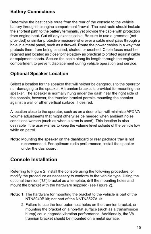
Battery Connections
Determine the best cable route from the rear of the console to the vehicle battery through the engine compartment firewall. The best route should include the shortest path to the battery terminals, yet provide the cable with protection from engine heat. Cut off any excess cable. Be sure to use a grommet (not provided) or similar protective measure wherever a cable must pass through a hole in a metal panel, such as a firewall. Route the power cables in a way that protects them from being pinched, chafed, or crushed. Cable fuses must be retained and located as close to the battery as practical to protect against cable or equipment shorts. Secure the cable along its length through the engine compartment to prevent displacement during vehicle operation and service.
Optional Speaker Location
Select a location for the speaker that will neither be dangerous to the operator nor damaging to the speaker. A trunnion bracket is provided for mounting the speaker. The speaker is normally hung under the dash near the right side of the console, however, the trunnion bracket permits mounting the speaker against a wall or other vertical surface, if desired.
A location close to the operator, such as on a door pillar, will minimize APX VA volume adjustments that might otherwise be needed when ambient noise conditions worsen (such as when a siren is used). This location is also desirable if the user wishes to keep the volume level outside of the vehicle low while on patrol.
Note: Mounting the speaker on the dashboard or rear package tray is not recommended. For optimum radio performance, install the speaker under the dashboard.
Console Installation
Referring to Figure 2, install the console using the following procedure, or modify the procedure as necessary to conform to the vehicle type. Using the optional trunnion (“U”) bracket as a template, drill the mounting holes and mount the bracket with the hardware supplied (see Figure 2).
Note: 1. The hardware for mounting the bracket to the vehicle is part of the NTN8940B kit; not part of the NNTN8527A kit.
2. Failure to use the four outermost holes on the trunnion bracket, or mounting the bracket on a non-flat surface (such as a transmission hump) could degrade vibration performance. Additionally, the VA trunnion bracket should be mounted on a metal surface.
15
MN000350A01.book Page 16 Tuesday, March 29, 2016 2:14 PM
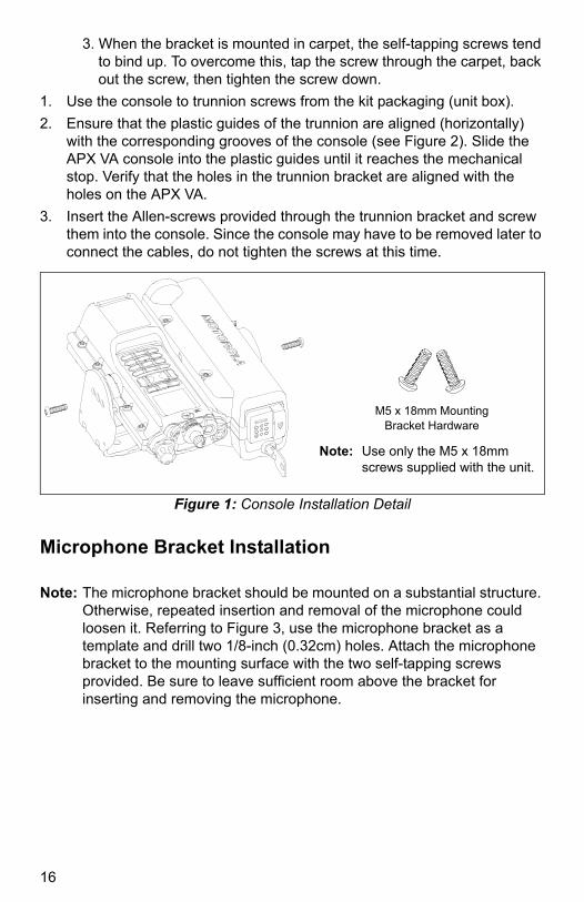
3. When the bracket is mounted in carpet, the self-tapping screws tend to bind up. To overcome this, tap the screw through the carpet, back out the screw, then tighten the screw down.
1. Use the console to trunnion screws from the kit packaging (unit box).
2. Ensure that the plastic guides of the trunnion are aligned (horizontally) with the corresponding grooves of the console (see Figure 2). Slide the APX VA console into the plastic guides until it reaches the mechanical stop. Verify that the holes in the trunnion bracket are aligned with the holes on the APX VA.
3. Insert the Allen-screws provided through the trunnion bracket and screw them into the console. Since the console may have to be removed later to connect the cables, do not tighten the screws at this time.
Figure 1: Console Installation Detail
Microphone Bracket Installation
Note: The microphone bracket should be mounted on a substantial structure. Otherwise, repeated insertion and removal of the microphone could loosen it. Referring to Figure 3, use the microphone bracket as a template and drill two 1/8-inch (0.32cm) holes. Attach the microphone bracket to the mounting surface with the two self-tapping screws provided. Be sure to leave sufficient room above the bracket for inserting and removing the microphone.
Note: Use only the M5 x 18mm screws supplied with the unit.
M5 x 18mm MountingBracket Hardware
16

MN000350A01.book Page 17 Tuesday, March 29, 2016 2:14 PM
Figure 2: Console Installation Detail
Figure 3: Microphone Bracket Installation Detail
Legend:
1. No. 10-12 x 1-1/4” Self-Drilling, Self-Tapping Screw (Quantity 4)
2. M5 x 18mm Screws (Quantity 2)
Cut-Away of Dash
0.125” (0.3175 cm) Dia. Holes
Trunnion Bracket (Optional)
Console
1
Plastic Guides
Groove
2
Trunnion Bracket (Optional)2
1
Dash Mount
Floor Mount
or
Bracket
Self-tapping Screws No. 8 – 15 x 1/2”
1/8” DIA. Holes
17

MN000350A01.book Page 18 Tuesday, March 29, 2016 2:14 PM
Visor Microphone Installation
Note: When connecting the Visor Microphone (RMN5054) to the APX VA, do not connect any wire of the Visor Microphone to pin 17 of Connector J1 on the APX VA. The instructions to do this in the IMPRES Visor Microphone User Guide do not apply to the APX VA product. Two other wires should be connected to pins 1 and 23 as instructed.
1. Referring to Figure 4, clip the microphone to the vehicle’s visor.
2. To avoid visual or physical obstruction, route the microphone cable down inside the door molding and beneath the seat. Allow sufficient slack in the connector end of the cable to reach the APX VA.
Figure 4: Visor Microphone Installation Detail
Antenna Installation
IMPORTANT: To ensure optimum performance and compliance with RF Energy Safety Standards, these antenna installation guidelines and instructions are limited to metal body vehicles with appropriate ground planes and take into account the potential exposure of back seat passengers and bystanders outside the vehicle.
Selecting an Antenna Site/Location on a Metal Body Vehicle:
1. External installation – Check the requirements of the antenna supplier and install the vehicle antenna external to a metal body vehicle in accordance with those requirements.
2. Roof top – For optimum performance and compliance with RF Energy Safety Standards, mount the antenna in the center area of the roof.
3. Trunk lid – On some vehicles with clearly defined, flat trunk lids, the antennas (see the following restrictions) can also be mounted on the center area of the trunk lid. For vehicles without clearly defined, flat trunk lids (such as hatchback autos, sports utility vehicles, and pick-up trucks), mount the antenna in the center area of the roof.
Visor Hands-Free Microphone
18
MN000350A01.book Page 19 Tuesday, March 29, 2016 2:14 PM
Before installing an antenna on the trunk lid,
• Ensure that the distance from the antenna location on the trunk lid will be at least 36 inches (90 cm) from the front surface of the rear seat-back to ensure compliance with RF Energy Safety Standards.
• Ensure that the trunk lid is grounded by connecting grounding straps between the trunk lid and the vehicle chassis.
Mounting restrictions for certain radio models:
a. For all VHF and UHF models, the 1/4 wave antenna should be mounted only in the center area of the roof, not on the trunk lid, to ensure compliance with RF Energy Safety Standards.
b. Ensure that the antenna cable can be easily routed to the APX VA. Route the antenna cable as far away as possible from any vehicle electronic control units and associated wiring.
c. Check that the antenna location for any electrical interference.
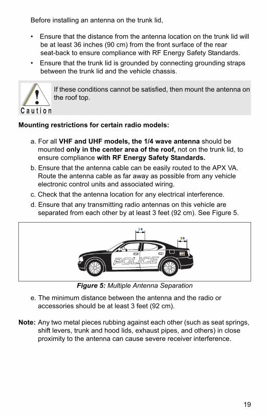
d. Ensure that any transmitting radio antennas on this vehicle are separated from each other by at least 3 feet (92 cm). See Figure 5.
Figure 5: Multiple Antenna Separation
e. The minimum distance between the antenna and the radio or accessories should be at least 3 feet (92 cm).
Note: Any two metal pieces rubbing against each other (such as seat springs, shift levers, trunk and hood lids, exhaust pipes, and others) in close proximity to the antenna can cause severe receiver interference.
If these conditions cannot be satisfied, then mount the antenna on the roof top.
19
MN000350A01.book Page 20 Tuesday, March 29, 2016 2:14 PM
Mini-UHF Connection
Note: 1. The RF connector (J3) on APX VA console is a mini-UHF jack, and must be mated with either an antenna mini-UHF plug (P3) or an appropriate adapter (part numbers: 5880367B21 [mini-UHF-to-N]; 5880367B22 [mini-UHF-to-UHF]; or 5880367B24 [mini-UHF-to-TNC]).
To ensure a secure connection of an antenna cable’s mini-UHF plug to an APX VA mini-UHF jack, their interlocking features must be properly engaged. If they are not properly engaged, the system will loosen. Using a tool (pliers or wrench) will not overcome a poor engagement, and is not recommended.
2. Applying excessive force with a tool can cause damage to the antenna or the connector (such as stripping threads, deforming the collar or connector, or causing the connector to twist in the housing opening and break).
The mini-UHF connector tool (part number HLN6695) is designed to securely tighten the antenna plug-APX VA jack connection without damaging either the plug or the jack.
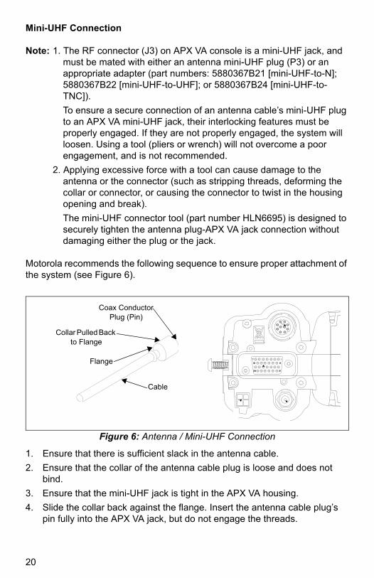
Motorola recommends the following sequence to ensure proper attachment of the system (see Figure 6).
Figure 6: Antenna / Mini-UHF Connection
1. Ensure that there is sufficient slack in the antenna cable.
2. Ensure that the collar of the antenna cable plug is loose and does not bind.
3. Ensure that the mini-UHF jack is tight in the APX VA housing.
4. Slide the collar back against the flange. Insert the antenna cable plug’s pin fully into the APX VA jack, but do not engage the threads.
Cable
Flange
Collar Pulled Back to Flange
Coax Conductor Plug (Pin)
20
MN000350A01.book Page 21 Tuesday, March 29, 2016 2:14 PM
5. Ensure that the plug’s and jack’s interlocking features are fully seated. Check this by grasping the crimp on the cable jack, rotating the cable, and noting any movement. If the features are seated correctly, there should be NO movement.
6. Finger-tighten the antenna cable plug’s collar onto the APX VA’s jack.
7. Give a final tug, by hand, to the collar, and retighten by hand as firmly as possible.
Note: Do not use pliers or any other device to grip the tightening tool. It has been designed to allow you to achieve proper torque on the collar without over tightening. Over tightening the collar can damage the connector and the APX VA.
Console Cabling
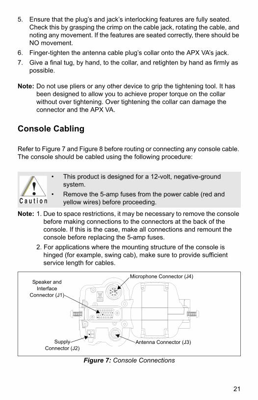
Refer to Figure 7 and Figure 8 before routing or connecting any console cable. The console should be cabled using the following procedure:
Note: 1. Due to space restrictions, it may be necessary to remove the console before making connections to the connectors at the back of the console. If this is the case, make all connections and remount the console before replacing the 5-amp fuses.
2. For applications where the mounting structure of the console is hinged (for example, swing cab), make sure to provide sufficient service length for cables.
Figure 7: Console Connections
• This product is designed for a 12-volt, negative-ground system.
• Remove the 5-amp fuses from the power cable (red and yellow wires) before proceeding.
Microphone Connector (J4)
Antenna Connector (J3)
Speaker and Interface
Connector (J1)
Supply Connector (J2)
21
MN000350A01.book Page 22 Tuesday, March 29, 2016 2:14 PM
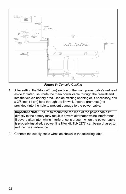
Figure 8: Console Cabling
1. After setting the 2-foot (61 cm) section of the main power cable’s red lead aside for later use, route the main power cable through the firewall and into the vehicle battery area. Use an existing opening or, if necessary, drill a 3/8-inch (1 cm) hole through the firewall. Insert a grommet (not provided) into the hole to prevent damage to the power cable.
2. Connect the supply cable wires as shown in the following table.
5-AMPBLADE-TYPE
FUSE
5-AMPBLADE-TYPE
FUSEVEHICLEANTENNA
FUSEBOX
MOBILEMICROPHONE
13.8 VOLTVEHICLEBATTERY
RED
YELLOW
BLACK
OPTIONALSPEAKER
A+
SWITCHEDA+
FIREWALL
GROMMET
VEHICLECHASSIS
OR
Important Note: Failure to mount the red lead of the power cable kit directly to the battery may result in severe alternator whine interference. If severe alternator whine interference is present when the power cable is properly installed, a power line filter kit, TLN5277, can be purchased to reduce the interference.
22
MN000350A01.book Page 23 Tuesday, March 29, 2016 2:14 PM
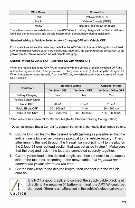
*After vehicle has been off for 30 minutes (Note: Standard Wiring Configuration).
**Does not include Boost Current (to support transmit) under totally discharged battery.
3. Cut the long red lead to the desired length (as long as possible so that the in-line fuse is located as close as practical to the vehicle battery). Then, after running the lead through the firewall, connect (crimp) it to the plug on the 2-foot (61 cm) red lead section that was set aside in step 1. Make sure that the plug and jack in the lead are connected securely together.
4. Cut the yellow lead to the desired length, and then connect it to the supply side of the fuse box, according to the above table. It is important not to connect the yellow wire to the red lead.
5. Cut the black lead to the desired length, then connect it to the vehicle chassis.
Wire Color Connect to
Red Vehicle battery (+)
Black Vehicle Chassis (GND)
Yellow Fuse box (see below for details)
The yellow wire controls whether or not the APX VA radio battery charger will be “live” at all times. Consider the functionality and vehicle battery drain current below during installation.
Standard Wiring to Vehicle Switched A+ – Charging OFF with Vehicle OFF
For installations where the radio may be left in the APX VA with the vehicle’s ignition switched OFF and minimal vehicle battery drain current is important, the standard wiring connection of the yellow wire to vehicle switched A+ will disable charging.
Optional Wiring to Vehicle A+ – Charging ON with Vehicle OFF
When the radio is left in the APX VA for charging with the vehicle’s ignition switched OFF, the optional wiring connection of the yellow wire to always-live vehicle (A+) will keep the charger ON. When the operator takes the radio from the APX VA, low vehicle battery drain current will occur. See (*) below.
ConditionStandard Wiring Optional Wiring
Vehicle = ON Vehicle = OFF* Vehicle = ON or OFF
Battery Charging Yes No Yes
Vehicle Battery Drain
Radio OUT 20 mA 2.5 mA 20 mA
Radio IN but OFF 30 – 900 mA 11 mA 30 – 900 mA
Radio In and ON** 125 – 2000 mA 30 – 1000 mA 125 – 2000 mA
It is NOT a good practice to connect the supply cable black lead directly to the negative (-) battery terminal; the APX VA could be damaged if there is a malfunction in the vehicle’s electrical system.
23
MN000350A01.book Page 24 Tuesday, March 29, 2016 2:14 PM
6. Dress the cable so that it does not obstruct any vehicle controls nor touch any hot or moving parts of the engine.
7. Connect power cable plug P2 to console jack J2.
8. If the optional external speaker is being installed, connect speaker cable plug P1 to console jack J1. Attach strain-relief S-hook (not provided) to the console; crimp the S-hook with a pair of pliers.
9. Connect external antenna cable plug P3 to console jack J3. If your model has a mini-UHF type connector, use Mini-UHF Connector Tool (part number REX4584) to tighten the connector.
10. Connect microphone cable plug P4 to console jack J4. Attach a strain-relief S-hook (not provided) to the console; crimp the S-hook with a pair of pliers (Required when a hand microphone is installed.)
11. Make certain that no radio is installed in the console, and then replace the two cable wire 5-amp fuses.
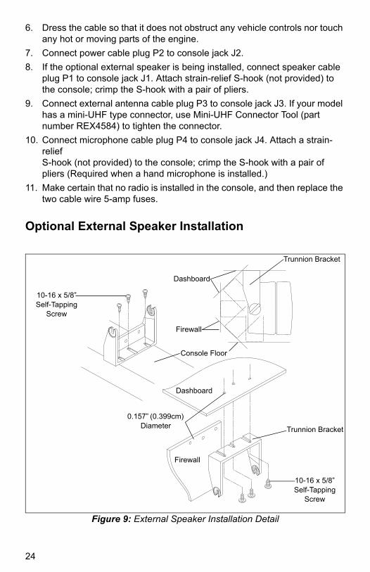
Optional External Speaker Installation
Figure 9: External Speaker Installation Detail
Trunnion Bracket
Dashboard
Firewall
Console Floor
10-16 x 5/8” Self-Tapping
Screw
Dashboard
0.157” (0.399cm) Diameter Trunnion Bracket
10-16 x 5/8” Self-Tapping
Screw
Firewall
24

MN000350A01.book Page 25 Tuesday, March 29, 2016 2:14 PM
The optional external speaker includes a trunnion bracket that permits the speaker to be mounted in a variety of configurations (see Figure 9).
Note: The trunnion bracket is used to permanently mount the speaker on the dashboard or other accessible areas, while permitting the speaker to be tilted to a desired angle.
1. Using the trunnion bracket as a template, drill the necessary mounting holes and secure the bracket with the self-tapping screws provided.
2. Position the external speaker onto the trunnion bracket, and secure it using the wing screws provided.
LED Surveillance Configuration (Option Wiring – User Configurable)
The APX VA’s LED indicator can be disabled for night use or surveillance operations by using the following optional wiring connections (refer to the Speaker and Interface Connector (J1) from Figure 7 and Figure 10).
• The LED indicator can be disabled by adding a jumper wire between J1 Connector Pin 17 (SURV) to Pin 14 (GND); this solution supports ONLY LED OFF Configuration; this would disable ALL LEDs including the Purple LED.
• The LED Indicator can be selectably disabled by installing a wired toggle switch (not provided) between J1 Connector Pin 17 (SURV) to Pin 14 (GND); this solution allows all use to readily enable or disable LED Surveillance Mode. In the LED Surveillance Mode, ALL LED indications are disabled, including error indications.
Note: If the switch option is chosen, a switch change only takes effect when the radio is inserted.
Figure 10: J1 Connector Definition
Note: Unlabeled pins are not connected and unsupported.
1
8
7
13
20
26
14
21
25

MN000350A01.book Page 26 Tuesday, March 29, 2016 2:14 PM
Installation Verification
After completing the installation of the vehicular adapter, check all electrical wiring for tight connections. Also, check all mechanical parts and wiring for tight and secure mounting. Check for proper operation of the console, microphone, speaker, and radio as described in the User Guide, Motorola Solutions publication MN000350A01-AA. Before placing the radio in the APX VA, check to see that the universal connector cover has been removed from the radio’s universal connector. Check existing equipment (sirens, lights, and other radio equipment) for proper operation.
Note: If alternator or other vehicular noise is present in the received signal or in the transmission, refer to “Reducing Noise Interference in Mobile Two-Way Radios,” Motorola Solutions publication 68P81109E33. This publication may be ordered separately from Motorola Solutions Accessories and Aftermarket Division (1-800422-4210).
Maintenance
For maintenance and service information, please refer to publication 68P81088C78, available from Motorola Solutions Accessories and Aftermarket Division (1-800-422-4210).
Table 2: J1 Connector Definition
Pin No. Pin Name Signal Definition
1 Ground Ground return, power
6 D- USB D- signal (USB white wire)
7 D+ USB D+ signal (USB green wire)
12 Vbus USB Vbus power (USB red wire)
14 Ground Ground return, audio
15 Emergency Emergency switch input
16 PTT PTT input
17a
aWhen connecting the Visor Microphone (RMN5054) to the APX VA, do not connect any wire of the Visor Microphone to pin 17 of Connector J1 on the APX VA. The instructions to do this in the IMPRES Visor Microphone User Guide do not apply to the APX VA product. Two other wires should be connected to pins 1 and 23 as instructed.
Surveillance Surveillance mode input
20 Spkr+ Speaker+
23 Visor Mic Visor microphone input
26 Spkr- Speaker-
26

MN000350A01.book Page 27 Tuesday, March 29, 2016 2:14 PM
Operational Warnings
!W A R N I N G
!Vehicles With an Air Bag
Do not place a portable radio or install radio communications equipment in the area over an air bag or in the air bag deployment
area. Air bags inflate with great force. If a portable radio is placed in the air bag deployment area and the air bag inflates, the radio may be propelled with great force and cause serious injury to occupants of the vehicle.
• Installation of vehicle communication equipment should be performed by a professional installer or technician qualified in the requirements for such installations. An airbag’s size, shape, and deployment area can vary by vehicle make, model, and front compartment configuration (such as bench seat vs. bucket seats).
• Contact the vehicle manufacturer’s corporate headquarters, if necessary, for specific airbag information for the vehicle make, model, and front compartment configuration involved in your communication equipment installation.
Potentially Explosive Atmospheres
Turn your radio OFF and eject it from the APX VA in any area with a potentially explosive atmosphere. It is rare, but your APX VA or its accessories could generate sparks. Sparks in such areas could cause an explosion or fire, resulting in bodily injury or even death.
Note: The areas with potentially explosive atmospheres referred to above include fueling areas such as: below decks on boats; fuel or chemical transfer or storage facilities; areas where the air contains chemicals or particles, such as grain, dust, or metal powders; and any other area where you would normally be advised to turn off a vehicle engine. Areas with potentially explosive atmospheres are often, but not always, posted.
Do not transport or store flammable gas, liquid, or explosives in the compartment of your vehicle that contains your APX VA or accessories.
Vehicles powered by liquefied petroleum gas (such as propane or butane)
must comply with the National Fire Protection standard (NFPA-58). For a
copy of this standard, contact the National Fire Protection Association, One
Battery Park, Quincy, MA. Attn.: Publications Sales Division.
27
MN000350A01.book Page 28 Tuesday, March 29, 2016 2:14 PM
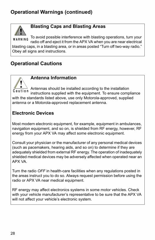
Operational Warnings (continued)
Operational Cautions
Blasting Caps and Blasting Areas
To avoid possible interference with blasting operations, turn your radio off and eject it from the APX VA when you are near electrical
blasting caps, in a blasting area, or in areas posted “Turn off two-way radio.” Obey all signs and instructions.
!W A R N I N G
!
Antenna Information
Antennas should be installed according to the installation instructions supplied with the equipment. To ensure compliance
with the standards listed above, use only Motorola-approved, supplied antenna or a Motorola-approved replacement antenna.
Electronic Devices
Most modern electronic equipment, for example, equipment in ambulances, navigation equipment, and so on, is shielded from RF energy, however, RF energy from your APX VA may affect some electronic equipment.
Consult your physician or the manufacturer of any personal medical devices (such as pacemakers, hearing aids, and so on) to determine if they are adequately shielded from external RF energy. The operation of inadequately shielded medical devices may be adversely affected when operated near an APX VA.
Turn the radio OFF in health-care facilities when any regulations posted in the areas instruct you to do so. Always request permission before using the radio or APX VA near medical equipment.
RF energy may affect electronics systems in some motor vehicles. Check with your vehicle manufacturer’s representative to be sure that the APX VA will not affect your vehicle’s electronic system.
28
MN000350A01.book Page 29 Tuesday, March 29, 2016 2:14 PM
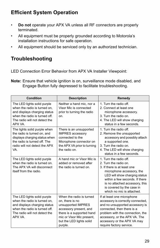
Efficient System Operation
• Do not operate your APX VA unless all RF connectors are properly terminated.
• All equipment must be properly grounded according to Motorola’s installation instructions for safe operation.
• All equipment should be serviced only by an authorized technician.
Troubleshooting
LED Connection Error Behavior from APX VA Installer Viewpoint:
Note: Ensure that vehicle ignition is on, surveillance mode disabled, and Engage Button fully depressed to facilitate troubleshooting.
Condition Description Remedy
The LED lights solid purple when the radio is turned on, and displays charging status when the radio is turned off. The radio will not detect the APX VA.
Neither a hand mic, nor a Visor Mic is connected prior to turning the radio on.
1. Turn the radio off.2. Connect at least one
microphone accessory.3. Turn the radio on.4. The LED will show charging
status in a few seconds.
The lights solid purple when the radio is turned on, and displays charging status when the radio is turned off. The radio will not detect the APX VA.
There is an unsupported IMPRES accessory connected to the Microphone connector on the APX VA prior to turning the radio on.
1. Turn the radio off.2. Remove the unsupported
accessory and possibly attach a supported one.
3. Turn the radio on.4. The LED will show charging
status in a few seconds.
The LED lights solid purple when the radio is turned on. The APX VA will disconnect itself from the radio.
A hand mic or Visor Mic is added or removed after the radio is turned on.
1. Turn the radio off.2. Turn the radio on.3. If there is at least one
microphone accessory, the LED will show charging status within a few seconds. If there is no attached accessory, this is covered by the case in which no mic is attached.
The LED lights solid purple when the radio is turned on, and displays charging status when the radio is turned off. The radio will not detect the APX VA.
When the radio is turned on, there is no unsupported IMPRES accessory present, and there is a supported hand mic or Visor Mic present, but the LED lights solid purple.
If at least one microphone accessory is correctly connected, and no unsupported accessory is connected, then there is a problem with the connection, the accessory, or the APX VA. The accessory or the APX VA may require factory service.
29
MN000350A01.book Page 30 Tuesday, March 29, 2016 2:14 PM
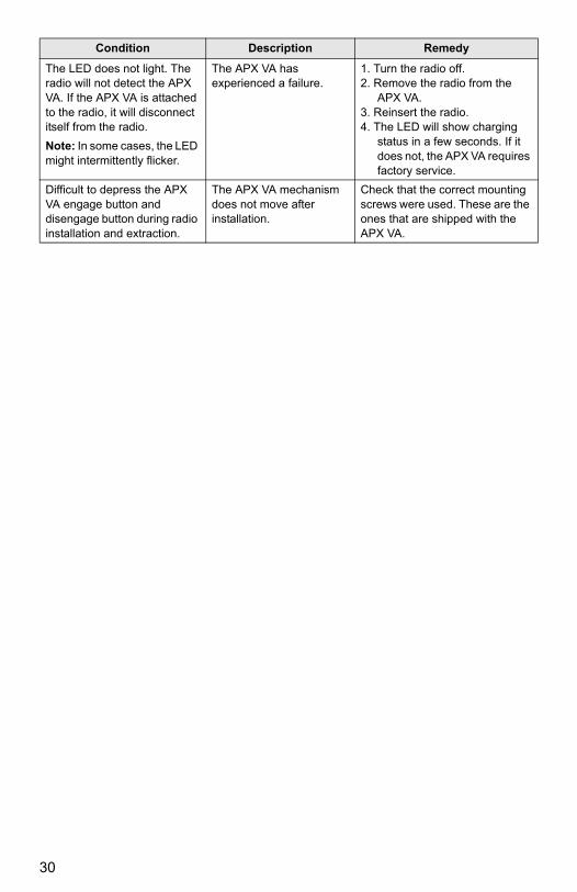
The LED does not light. The radio will not detect the APX VA. If the APX VA is attached to the radio, it will disconnect itself from the radio.
Note: In some cases, the LED might intermittently flicker.
The APX VA has experienced a failure.
1. Turn the radio off.2. Remove the radio from the
APX VA.3. Reinsert the radio.4. The LED will show charging
status in a few seconds. If it does not, the APX VA requires factory service.
Difficult to depress the APX VA engage button and disengage button during radio installation and extraction.
The APX VA mechanism does not move after installation.
Check that the correct mounting screws were used. These are the ones that are shipped with the APX VA.
Condition Description Remedy
30

MN000350A01.book Page 31 Tuesday, March 29, 2016 2:14 PM
ASTRO™ APX™ Vehicular Adapter (APX VA) User Guide
Product Safety and RF Exposure Compliance
ATTENTION!
This radio is restricted to occupational use only to satisfy FCC RF energy exposure requirements. Before using this product, read the RF energy awareness information and operating instructions in the Product Safety and RF Exposure section of this manual to ensure compliance with RF energy exposure limits.
For a list of Motorola-approved antennas, batteries, and other accessories, visit the following web site which lists approved accessories or refer to “APX Vehicular Adapter (VA) System Compatibility Matrix” on page 1.
http://www.motorolasolutions.com
Safe and Efficient Operation of Motorola Two-Way Radios
Exposure to Radio Frequency (RF) Energy
National and International Standards and Guidelines Your Motorola Two-Way Radio, which generates and radiates radio frequency (RF) electromagnetic energy (EME), is designed to comply with National and International Standards and Guidelines regarding exposure of human beings to RF electromagnetic energy:
Radio Operation and Electromagnetic Energy (EME) Exposure
To ensure optimal radio performance and that human exposure to RF electromagnetic energy is within the guidelines set forth in the above standards, transmit with any vehicular adapter when people inside and outside the vehicle are no closer than the distance shown in Table 3.
Before using this product, read the operating instructions for safe usage contained in the RF Energy Exposure and Product Safety section of this manual.
31
MN000350A01.book Page 32 Tuesday, March 29, 2016 2:14 PM
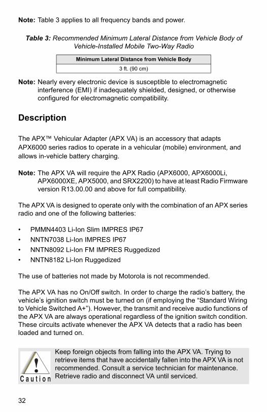
Note: Table 3 applies to all frequency bands and power.
Note: Nearly every electronic device is susceptible to electromagnetic interference (EMI) if inadequately shielded, designed, or otherwise configured for electromagnetic compatibility.
Description
The APX™ Vehicular Adapter (APX VA) is an accessory that adapts APX6000 series radios to operate in a vehicular (mobile) environment, and allows in-vehicle battery charging.
Note: The APX VA will require the APX Radio (APX6000, APX6000Li, APX6000XE, APX5000, and SRX2200) to have at least Radio Firmware version R13.00.00 and above for full compatibility.
The APX VA is designed to operate only with the combination of an APX series radio and one of the following batteries:
• PMMN4403 Li-Ion Slim IMPRES IP67
• NNTN7038 Li-Ion IMPRES IP67
• NNTN8092 Li-Ion FM IMPRES Ruggedized
• NNTN8182 Li-Ion Ruggedized
The use of batteries not made by Motorola is not recommended.
The APX VA has no On/Off switch. In order to charge the radio’s battery, the vehicle’s ignition switch must be turned on (if employing the “Standard Wiring to Vehicle Switched A+”). However, the transmit and receive audio functions of the APX VA are always operational regardless of the ignition switch condition. These circuits activate whenever the APX VA detects that a radio has been loaded and turned on.
Table 3: Recommended Minimum Lateral Distance from Vehicle Body of Vehicle-Installed Mobile Two-Way Radio
Minimum Lateral Distance from Vehicle Body
3 ft. (90 cm)
Keep foreign objects from falling into the APX VA. Trying to retrieve items that have accidentally fallen into the APX VA is not recommended. Consult a service technician for maintenance. Retrieve radio and disconnect VA until serviced.
32
MN000350A01.book Page 33 Tuesday, March 29, 2016 2:14 PM
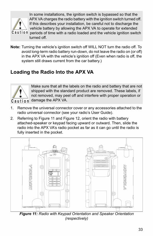
Note: Turning the vehicle’s ignition switch off WILL NOT turn the radio off. To avoid long-term radio battery run-down, do not leave the radio on (or off) in the APX VA with the vehicle’s ignition off (Even when radio is off, the system still draws current from the car battery.)
Loading the Radio Into the APX VA
1. Remove the universal connector cover or any accessories attached to the radio universal connector (see your radio’s User Guide).
2. Referring to Figure 11 and Figure 12, orient the radio with battery attached-speaker or keypad facing upward or outward. Then, slide the radio into the APX VA’s radio pocket as far as it can go until the radio is fully inserted in the pocket.
Figure 11: Radio with Keypad Orientation and Speaker Orientation (respectively)
In some installations, the ignition switch is bypassed so that the APX VA charges the radio battery with the ignition switch turned off. If this describes your installation, be careful not to discharge the vehicle battery by allowing the APX VA to operate for extended periods of time with a radio loaded and the vehicle ignition switch turned off.
Make sure that all the labels on the radio and battery that are not shipped with the standard product are removed. These labels, if not removed, may peel off and interfere with proper operation or damage the APX VA.
Pocket Warning
Label
33
MN000350A01.book Page 34 Tuesday, March 29, 2016 2:14 PM
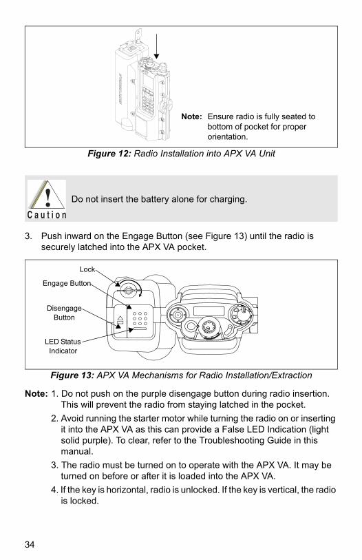
Figure 12: Radio Installation into APX VA Unit
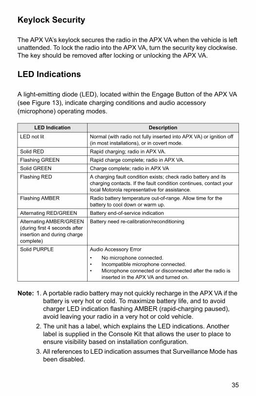
3. Push inward on the Engage Button (see Figure 13) until the radio is securely latched into the APX VA pocket.
Figure 13: APX VA Mechanisms for Radio Installation/Extraction
Note: 1. Do not push on the purple disengage button during radio insertion. This will prevent the radio from staying latched in the pocket.
2. Avoid running the starter motor while turning the radio on or inserting it into the APX VA as this can provide a False LED Indication (light solid purple). To clear, refer to the Troubleshooting Guide in this manual.
3. The radio must be turned on to operate with the APX VA. It may be turned on before or after it is loaded into the APX VA.
4. If the key is horizontal, radio is unlocked. If the key is vertical, the radio is locked.
Note: Ensure radio is fully seated to bottom of pocket for proper orientation.
Do not insert the battery alone for charging.
Lock
Engage Button
Disengage Button
LED Status Indicator
34
MN000350A01.book Page 35 Tuesday, March 29, 2016 2:14 PM
Keylock Security
The APX VA’s keylock secures the radio in the APX VA when the vehicle is left unattended. To lock the radio into the APX VA, turn the security key clockwise. The key should be removed after locking or unlocking the APX VA.
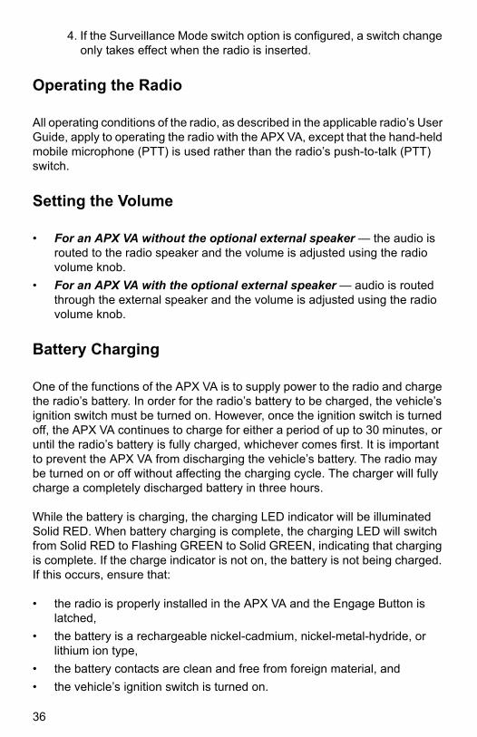
LED Indications
A light-emitting diode (LED), located within the Engage Button of the APX VA (see Figure 13), indicate charging conditions and audio accessory (microphone) operating modes.
Note: 1. A portable radio battery may not quickly recharge in the APX VA if the battery is very hot or cold. To maximize battery life, and to avoid charger LED indication flashing AMBER (rapid-charging paused), avoid leaving your radio in a very hot or cold vehicle.
2. The unit has a label, which explains the LED indications. Another label is supplied in the Console Kit that allows the user to place to ensure visibility based on installation configuration.
3. All references to LED indication assumes that Surveillance Mode has been disabled.
LED Indication Description
LED not lit Normal (with radio not fully inserted into APX VA) or ignition off (in most installations), or in covert mode.
Solid RED Rapid charging; radio in APX VA.
Flashing GREEN Rapid charge complete; radio in APX VA.
Solid GREEN Charge complete; radio in APX VA
Flashing RED A charging fault condition exists; check radio battery and its charging contacts. If the fault condition continues, contact your local Motorola representative for assistance.
Flashing AMBER Radio battery temperature out-of-range. Allow time for the battery to cool down or warm up.
Alternating RED/GREEN Battery end-of-service indication
Alternating AMBER/GREEN (during first 4 seconds after insertion and during charge complete)
Battery need re-calibration/reconditioning
Solid PURPLE Audio Accessory Error
• No microphone connected.• Incompatible microphone connected.• Microphone connected or disconnected after the radio is
inserted in the APX VA and turned on.
35
MN000350A01.book Page 36 Tuesday, March 29, 2016 2:14 PM
4. If the Surveillance Mode switch option is configured, a switch change only takes effect when the radio is inserted.
Operating the Radio
All operating conditions of the radio, as described in the applicable radio’s User Guide, apply to operating the radio with the APX VA, except that the hand-held mobile microphone (PTT) is used rather than the radio’s push-to-talk (PTT) switch.
Setting the Volume
• For an APX VA without the optional external speaker — the audio is routed to the radio speaker and the volume is adjusted using the radio volume knob.
• For an APX VA with the optional external speaker — audio is routed through the external speaker and the volume is adjusted using the radio volume knob.
Battery Charging
One of the functions of the APX VA is to supply power to the radio and charge the radio’s battery. In order for the radio’s battery to be charged, the vehicle’s ignition switch must be turned on. However, once the ignition switch is turned off, the APX VA continues to charge for either a period of up to 30 minutes, or until the radio’s battery is fully charged, whichever comes first. It is important to prevent the APX VA from discharging the vehicle’s battery. The radio may be turned on or off without affecting the charging cycle. The charger will fully charge a completely discharged battery in three hours.
While the battery is charging, the charging LED indicator will be illuminated Solid RED. When battery charging is complete, the charging LED will switch from Solid RED to Flashing GREEN to Solid GREEN, indicating that charging is complete. If the charge indicator is not on, the battery is not being charged. If this occurs, ensure that:
• the radio is properly installed in the APX VA and the Engage Button is latched,
• the battery is a rechargeable nickel-cadmium, nickel-metal-hydride, or lithium ion type,
• the battery contacts are clean and free from foreign material, and
• the vehicle’s ignition switch is turned on.
36
MN000350A01.book Page 37 Tuesday, March 29, 2016 2:14 PM
If the battery temperature is out-of-range, the Charge LED will illuminate Flashing AMBER and charging will temporarily stop.
One of the features of the APX VA’s charger is its ability to change from rapid charge (Solid RED LED indication) to trickle charge (Flashing GREEN LED indication), and complete charge (Solid GREEN LED indication) once full battery charge has been achieved. A fully-charged battery that has just been re-inserted into the charger may require a few minutes to change to complete charging and give a Solid GREEN LED indication.
If a totally discharged battery is placed in the APX VA, the radio’s receiver will begin to function normally within a few seconds. Transmission should not be attempted for about 30 seconds (longer if the radio battery is hot or cold) when using a high-power radio, and should be kept to a minimum for the first few minutes. Low-power radios will allow normal operation sooner.
Removing the Radio from the APX VA
1. If applicable, unlock the radio by turning the key clockwise.
2. Press the purple disengage button (see Figure 13) to release the radio from the APX VA.
Note: If the radio fails to eject, hold down the purple disengage button and pull out the radio. To ensure proper ejection in the future, insert and remove the radio several times.
Recommended Maintenance and Cleaning
Contact material technologies used in the APX VA and APX Radios are engineered to provide reliable interconnect. It is important that the electrical contact interface remains clean and free of foreign material to ensure reliable performance. To maintain optimal performance of the contact interface, Motorola Solutions recommends inspecting and cleaning the contacts every 6 months with DeoxIT® GOLD cleaner/lubricant pen (Supplier CAIG Labs, P/N G100P). DeoxIT® GOLD cleaner/lubricant is available at numerous electronics suppliers (McMaster Carr, Fry's, Radio Shack, etc.) and directly from the manufacturer. The pen based package is recommended as it provides better cleaning action and access to the contacts. Prior to applying the lubricant/cleaner, wipe the contacts with lint-free swabs to remove any dirt or foreign material. Per the manufacturer's instructions, shake the pen, depress the pen tip until fluid begins to flow and saturates the felt tip. Then with short wiping strokes apply the lubricant/cleaner to the contacts.
37

MN000350A01.book Page 38 Tuesday, March 29, 2016 2:14 PM
Troubleshooting
LED Connection Error Behavior and other conditions from APX VA User View point:
Note: Ensure vehicle ignition is on, Surveillance Mode disabled, and Engage Button fully depressed to facilitate troubleshooting.
Condition Description Remedy
The LED lights solid purple when the radio is turned on, and displays charging status when the radio is turned off. The radio will not detect the APX VA.
Neither a hand mic, nor a Visor Mic is connected prior to turning the radio on.
Note: Microphone accessory should be installed by the installer.
If the user removed any accessories, then the error can be cleared with the following steps:
1. Turn off the radio.2. Attach at least one accessory.3. Turn the radio on.4. The LED will show charging status after the
radio is turned off and continue to do so after the radio is turned on.
If the error persists, please contact the installer.
The LED lights solid purple when the radio is turned on, and displays charging status when the radio is turned off. The radio will not detect the APX VA.
There is an unsupported IMPRES accessory connected to the Microphone connector on the APX VA prior to turning the radio on.
Note: Microphone accessory should be installed by the installer. The installer will ensure that the correct accessory is installed.
If the user attached an unsupported accessory, the error can be cleared with the following steps:
1. Turn off the radio.2. Remove the unsupported accessory.3. Turn the radio on.4. If there is at least one attached accessory,
the LED will switch to showing charging status when the radio is turned off and continue to do so after the radio is turned on. If there is no attached accessory, this is covered by the case in which no mic is attached.
If the error persists, please contact the installer.
38
MN000350A01.book Page 39 Tuesday, March 29, 2016 2:14 PM
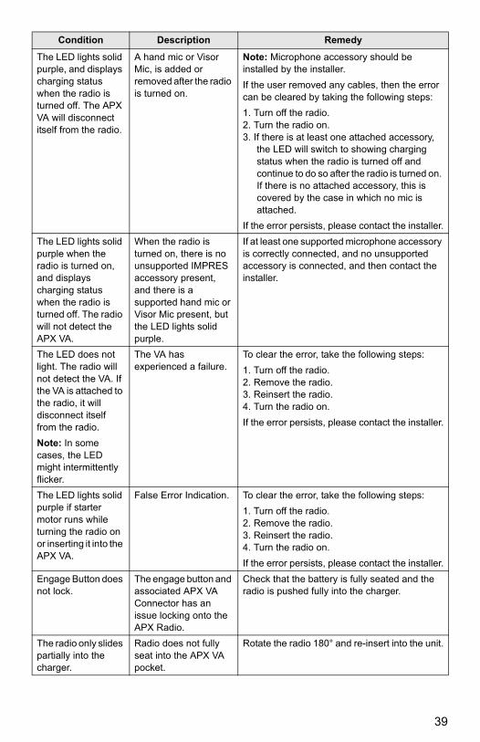
The LED lights solid purple, and displays charging status when the radio is turned off. The APX VA will disconnect itself from the radio.
A hand mic or Visor Mic, is added or removed after the radio is turned on.
Note: Microphone accessory should be installed by the installer.
If the user removed any cables, then the error can be cleared by taking the following steps:
1. Turn off the radio.2. Turn the radio on.3. If there is at least one attached accessory,
the LED will switch to showing charging status when the radio is turned off and continue to do so after the radio is turned on. If there is no attached accessory, this is covered by the case in which no mic is attached.
If the error persists, please contact the installer.
The LED lights solid purple when the radio is turned on, and displays charging status when the radio is turned off. The radio will not detect the APX VA.
When the radio is turned on, there is no unsupported IMPRES accessory present, and there is a supported hand mic or Visor Mic present, but the LED lights solid purple.
If at least one supported microphone accessory is correctly connected, and no unsupported accessory is connected, and then contact the installer.
The LED does not light. The radio will not detect the VA. If the VA is attached to the radio, it will disconnect itself from the radio.
Note: In some cases, the LED might intermittently flicker.
The VA has experienced a failure.
To clear the error, take the following steps:
1. Turn off the radio.2. Remove the radio.3. Reinsert the radio.4. Turn the radio on.
If the error persists, please contact the installer.
The LED lights solid purple if starter motor runs while turning the radio on or inserting it into the APX VA.
False Error Indication. To clear the error, take the following steps:
1. Turn off the radio.2. Remove the radio.3. Reinsert the radio.4. Turn the radio on.
If the error persists, please contact the installer.
Engage Button does not lock.
The engage button and associated APX VA Connector has an issue locking onto the APX Radio.
Check that the battery is fully seated and the radio is pushed fully into the charger.
The radio only slides partially into the charger.
Radio does not fully seat into the APX VA pocket.
Rotate the radio 180° and re-insert into the unit.
Condition Description Remedy
39

MN000350A01.book Page 40 Tuesday, March 29, 2016 2:14 PM
Notes
40

MN000350A01.book Page 1 Tuesday, March 29, 2016 2:14 PM

MOTOROLA, MOTO, MOTOROLA SOLUTIONS and the Stylized M logo are trademarks or registered trademarks of Motorola Trademark Holdings, LLC and are used under license. All other trademarks are the property of their respective owners.
© 2015 Motorola Solutions, Inc. All rights reserved.
*MN000350A01*MN000350A01-AB
MN000350A01.book Page 2 Tuesday, March 29, 2016 2:14 PM